Embed Size (px)
Citation preview
1
Wireless Power Transmission for Solar Power Satellite (SPS) (Second Draft by N. Shinohara)
1. Theoretical Background
It is known that electromagnetic energy also associated with the propagation of the
electromagnetic waves. We can use theoretically all electromagnetic waves for a wireless power
transmission (WPT). The difference between the WPT and communication systems is only efficiency.
The Maxwell’s Equations indicate that the electromagnetic field and its power diffuse to all
directions. Although we transmit the energy in the communication system, the transmitted energy is
diffused to all directions. Although the received power is enough for a transmission of information,
the efficiency from the transmitter to receiver is quiet low. Therefore, we do not call it the WPT
system.
Typical WPT is a point-to-point power transmission. For the WPT, we had better concentrate
power to receiver. It was proved that the power transmission efficiency can approach close to 100%.
We can more concentrate the transmitted microwave power to the receiver aperture areas with taper
method of the transmitting antenna power distribution. Famous power tapers of the transmitting
antenna are Gaussian taper, Taylor distribution, and Chebychev distribution. These taper of the
transmitting antenna is commonly used for suppression of sidelobes. It corresponds to increase the
power transmission efficiency. Concerning the power transmission efficiency of the WPT, there are
some good optical approaches in Russia[5][6].
Future suitable and largest application of the WPT via microwave is a Space Solar Power
Satellite (SPS). The SPS is a gigantic satellite designed as an electric power plant orbiting in the
Geostationary Earth Orbit (GEO). It consists of mainly three segments; solar energy collector to
convert the solar energy into DC (direct current) electricity, DC-to-microwave converter, and large
antenna array to beam down the microwave power to the ground. The first solar collector can be
either photovoltaic cells or solar thermal turbine. The second DC-to-microwave converter of the SPS
can be either microwave tube system and/or semiconductor system. It may be their combination. The
third segment is a gigantic antenna array. Table 1.1 shows some typical parameters of the
transmitting antenna of the SPS. An amplitude taper on the transmitting antenna is adopted in order
to increase the beam collection efficiency and to decrease sidelobe level in almost all SPS design. A
typical amplitude taper is called 10 dB Gaussian in which the power density in the center of the
transmitting antenna is ten times larger than that on the edge of the transmitting antenna.
The SPS is expected to realize around 2030. Before the realization of the SPS, we can consider the
other application of the WPT. In resent years, mobile devices advance quickly and require
decreasing power consumption. It means that we can use the diffused weak microwave power as a
power source of the mobile devices with low power consumption such as RF-ID. The RF-ID is a

2
radio IC-tug with wireless power transmission and wireless information. This is a new WPT
application like broadcasting.
Table 1.1 Typical parameters of the transmitting antenna of the SPS [7]
Model Old JAXA
model JAXA1 model JAXA2 Model
NASA/DOE model
Frequency 5.8 GHz 5.8 GHz 5.8 GHz 2.45 GHz Diameter of transmitting antenna
2.6 kmφ 1 kmφ 1.93 kmφ 1 kmφ
Amplitude taper 10 dB Gaussian 10 dB Gaussian 10 dB Gaussian 10 dB GaussianOutput power (beamed to earth)
1.3 GW 1.3 GW 1.3 GW 6.72 GW
Maximum power density at center
63 mW/ cm2 420 mW/cm2 114 mW/cm2 2.2 W/ cm2
Minimum power density at edge
6.3 mW/ cm2 42 mW/ cm2 11.4 mW/cm2 0.22 W/ cm2
Antenna spacing 0.75 λ 0.75 λ 0.75 λ 0.75 λ Power per one antenna (Number of elements)
Max. 0.95 W (3.54 billion)
Max. 6.1W (540 million)
Max. 1.7 W (1,950 million)
Max. 185 W (97 million)
Rectenna Diameter 2.0 kmφ 3.4 kmφ 2.45 kmφ 1 kmφ Maximum Power
Density 180 mW/cm2 26 mW/cm2 100 mW/cm2 23 mW/cm2
Collection Efficiency 96.5 % 86 % 87 % 89 % JAXA : Japan Aerospace Exploration Agency, NASA : National Aeronautics and Space
Administration, DOE : U.S. Department Of Energy
References
[1] Iskander, M. F., “Electromagnetic Fields and Waves”, Prentice Hall, 1992
[2] Ed. Chang, K., “handbook of Microwave and Optical Components Volume 1”, A
Wiley-Interscience Publication, 1989, p.511
[3] Goubau, G. and F. Schwering, “On the guided propagation of electromagnetic wave beams”, IRE
Trans. Antennas and Propagation, AP-9, 1961, pp. 248-256
[4] Brown, W. C., “Beamed microwave power transmission and its application to space”, IEEE
Trans. Microwave Theory Tech., vol. 40, no. 6, 1992, pp.1239-1250
[5] Vaganov, R. B., “Maximum Power Transmission between Two Apertures with the Help of a
Wave Beam”, Journal of Communications Technology and Electronics, vol.42, no.4, 1997,
pp.430-435
[6] Garmash, V.N., Katsenelenbaum B.Z., S.S.Shaposhnikov, S.S., V. N. Tioulpakov, and R. B.
Vaganov, “Some Possible Methods of the Diffraction Expansion Decrease”, Proc.of SPS’97,
1997. pp.87-92
3
[7] Supporting Document for the URSI White Paper on Solar Power Satellite Systems (in print),
2006
4
2. History of Wireless Power Transmission
In 1864, James C. Maxwell predicted the existence of radio waves by means of mathematical
model. In 1884, John H. Poynting realized that the Poynting Vector would play an important role in
quantifying the electromagnetic energy. In 1888, bolstered by Maxwell's theory, Heinrich Hertz first
succeeded in showing experimental evidence of radio waves by his spark-gap radio transmitter. The
prediction and Evidence of the radio wave in the end of 19th century was start of the wireless power
transmission.
At the same period of Marchese G. Marconi and Reginald Fessenden who are pioneers of
communication via radio waves, Nicola Tesla suggested an idea of the wireless power transmission
and carried out the first WPT experiment in 1899[1][2]. He said “This energy will be collected all
over the globe preferably in small amounts, ranging from a fraction of one to a few horse-power.
One of its chief uses will be the illumination of isolated homes”. He actually built a gigantic coil
which was connected to a high mast of 200-ft with a 3 ft-diameter ball at its top. He fed 300 kW
power to the Tesla coil resonated at 150 kHz. The RF potential at the top sphere reached 100 MV.
Unfortunately, he failed because the transmitted power was diffused to all directions with 150 kHz
radio waves whose wave length was 21 km.
To concentrate the transmitted power and to increase transmission efficiency, we have to use
higher frequency than that used by Tesla. In 1930s, much progress in generating high-power
microwaves, 1-10 GHz radio waves, was achieved by invention of the magnetron and the klystron.
After World War II, high power and high efficiency microwave tubes were advanced by
development of radar technology. We can
concentrate a power to receiver with microwaves.
We call the wireless power transmission with
microwaves as microwave power transmission
(MPT).
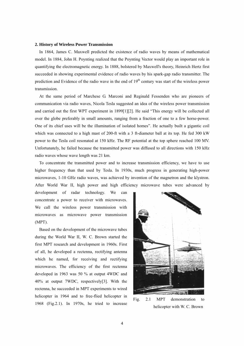
Based on the development of the microwave tubes
during the World War II, W. C. Brown started the
first MPT research and development in 1960s. First
of all, he developed a rectenna, rectifying antenna
which he named, for receiving and rectifying
microwaves. The efficiency of the first rectenna
developed in 1963 was 50 % at output 4WDC and
40% at output 7WDC, respectively[3]. With the
rectenna, he succeeded in MPT experiments to wired
helicopter in 1964 and to free-flied helicopter in
1968 (Fig.2.1). In 1970s, he tried to increase
Fig. 2.1 MPT demonstration to
helicopter with W. C. Brown

5
DC-RF-transmission-RF-DC total efficiency with 2.45 GHz microwave. In 1970, overall DC-DC
total efficiency was only 26.5 % at 39WDC in Marshall Space Flight Center. In 1975, DC-DC total
efficiency was finally 54 % at 495WDC with magnetron in Raytheon Laboratory (Fig.2.2). In
parallel, He and his team succeeded in the largest MPT demonstration in 1975 at the Venus Site of
JPL Goldstone Facility (Fig.2.3). Distance between a transmitting parabolic antenna, whose diameter
Fig.2.2 MPT Laboratory Experiment in 1975 by W. Brown [4]
Fig.2.3 First Ground-to-Ground MPT Experiment in 1975 at the Venus Site of JPL Goldstone
Facility
6
was 26m, and a rectenna array, whose size was 3.4 m
x 7.2 m, was 1 mile. The transmitted microwave of
2.388GHz was 450 kW from klystron and the
achieved rectified DC power was 30 kWDC with
82.5% rectifying efficiency. Based on the Brown’s
work, P. E. Glaser proposed a Solar Power Satellite
(SPS) in 1968[5].
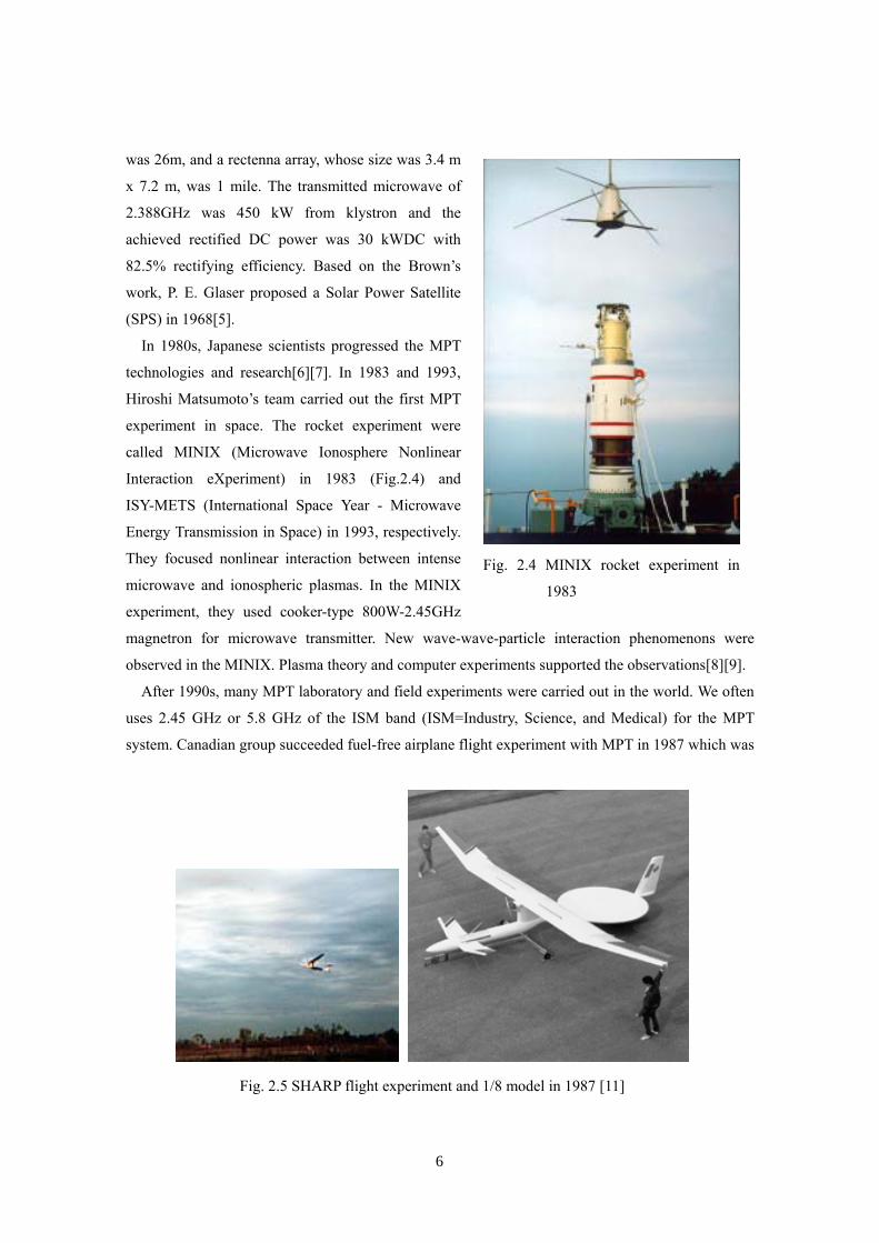
In 1980s, Japanese scientists progressed the MPT
technologies and research[6][7]. In 1983 and 1993,
Hiroshi Matsumoto’s team carried out the first MPT
experiment in space. The rocket experiment were
called MINIX (Microwave Ionosphere Nonlinear
Interaction eXperiment) in 1983 (Fig.2.4) and
ISY-METS (International Space Year - Microwave
Energy Transmission in Space) in 1993, respectively.
They focused nonlinear interaction between intense
microwave and ionospheric plasmas. In the MINIX
experiment, they used cooker-type 800W-2.45GHz
magnetron for microwave transmitter. New wave-wave-particle interaction phenomenons were
observed in the MINIX. Plasma theory and computer experiments supported the observations[8][9].
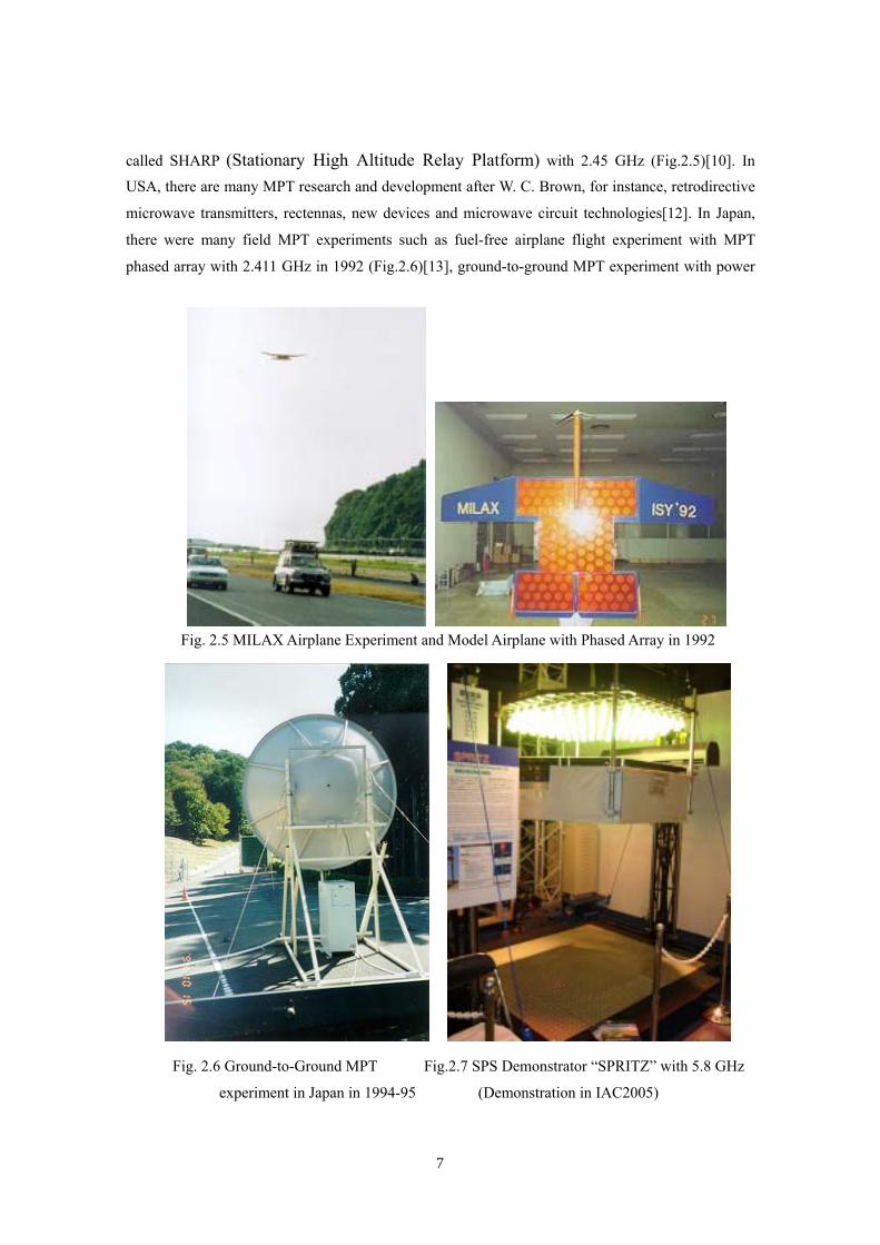
After 1990s, many MPT laboratory and field experiments were carried out in the world. We often
uses 2.45 GHz or 5.8 GHz of the ISM band (ISM=Industry, Science, and Medical) for the MPT
system. Canadian group succeeded fuel-free airplane flight experiment with MPT in 1987 which was
Fig. 2.4 MINIX rocket experiment in
1983
Fig. 2.5 SHARP flight experiment and 1/8 model in 1987 [11]
7
called SHARP (Stationary High Altitude Relay Platform) with 2.45 GHz (Fig.2.5)[10]. In
USA, there are many MPT research and development after W. C. Brown, for instance, retrodirective
microwave transmitters, rectennas, new devices and microwave circuit technologies[12]. In Japan,
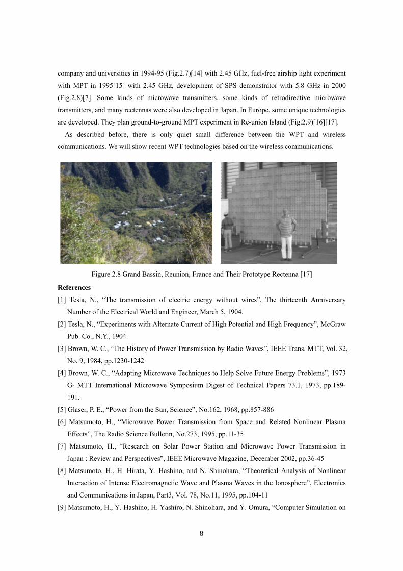
there were many field MPT experiments such as fuel-free airplane flight experiment with MPT
phased array with 2.411 GHz in 1992 (Fig.2.6)[13], ground-to-ground MPT experiment with power
Fig. 2.5 MILAX Airplane Experiment and Model Airplane with Phased Array in 1992
Fig. 2.6 Ground-to-Ground MPT Fig.2.7 SPS Demonstrator “SPRITZ” with 5.8 GHz
experiment in Japan in 1994-95 (Demonstration in IAC2005)
8
company and universities in 1994-95 (Fig.2.7)[14] with 2.45 GHz, fuel-free airship light experiment
with MPT in 1995[15] with 2.45 GHz, development of SPS demonstrator with 5.8 GHz in 2000
(Fig.2.8)[7]. Some kinds of microwave transmitters, some kinds of retrodirective microwave
transmitters, and many rectennas were also developed in Japan. In Europe, some unique technologies
are developed. They plan ground-to-ground MPT experiment in Re-union Island (Fig.2.9)[16][17].
As described before, there is only quiet small difference between the WPT and wireless
communications. We will show recent WPT technologies based on the wireless communications.
References
[1] Tesla, N., “The transmission of electric energy without wires”, The thirteenth Anniversary
Number of the Electrical World and Engineer, March 5, 1904.
[2] Tesla, N., “Experiments with Alternate Current of High Potential and High Frequency”, McGraw
Pub. Co., N.Y., 1904.
[3] Brown, W. C., “The History of Power Transmission by Radio Waves”, IEEE Trans. MTT, Vol. 32,
No. 9, 1984, pp.1230-1242
[4] Brown, W. C., “Adapting Microwave Techniques to Help Solve Future Energy Problems”, 1973
G- MTT International Microwave Symposium Digest of Technical Papers 73.1, 1973, pp.189-
191.
[5] Glaser, P. E., “Power from the Sun, Science”, No.162, 1968, pp.857-886
[6] Matsumoto, H., “Microwave Power Transmission from Space and Related Nonlinear Plasma
Effects”, The Radio Science Bulletin, No.273, 1995, pp.11-35
[7] Matsumoto, H., “Research on Solar Power Station and Microwave Power Transmission in
Japan : Review and Perspectives”, IEEE Microwave Magazine, December 2002, pp.36-45
[8] Matsumoto, H., H. Hirata, Y. Hashino, and N. Shinohara, “Theoretical Analysis of Nonlinear
Interaction of Intense Electromagnetic Wave and Plasma Waves in the Ionosphere”, Electronics
and Communications in Japan, Part3, Vol. 78, No.11, 1995, pp.104-11
[9] Matsumoto, H., Y. Hashino, H. Yashiro, N. Shinohara, and Y. Omura, “Computer Simulation on
Figure 2.8 Grand Bassin, Reunion, France and Their Prototype Rectenna [17]
9
Nonlinear Interaction of Intense Microwave with Space Plasmas”, Electronics and
Communications in Japan, Part3, Vol. 78, No.11, 1995, pp.89-103
[10] Schlesak, J. J. A. Alden and T. Ohno, A microwave powered high altitude platform, IEEE
MTT-S Int. Symp. Digest, 1988, pp.283-286
[11] http://friendsofcrc.ca/SHARP/sharp.html
[12] McSpadden, J. O. and J. C. Mankins, “Space Solar Power Programs and Microwave Wireless
Power Transmission Technology”, IEEE Microwave Magazine, December 2002, pp.46-57
[13] Matsumoto, H., et al., “MILAX Airplane Experiment and Model Airplane,” 12th ISAS Space
Energy Symposium, Tokyo, Japan, March 1993
[14] Shinohara N. and H. Matsumoto, “Dependence of dc Output of a Rectenna Array on the
Method of Interconnection of Its Array Element”, Electrical Engineering in Japan, Vol.125, No.1,
1998, pp.9-17
[15] Kaya, N., S. Ida, Y. Fujino, and M. Fujita, “Transmitting antenna system for airship
demonstration (ETHER), Space Energy and Transportation, Vol.1, No.4, 1996, pp.237-245
[16] Celeste, A., J-D. L. S. Luk, J. P. Chabriat, and G. Pignolet, “The Grand-Bassin Case Study:
Technical Aspects”, Proc. of SPS’97, 1997, pp.255-258
[17] Celeste, A., P. Jeanty, and G Pignolet, “Case study in Reunion island, Acta Astronautica”, vol.
54, 2004, pp. 253-258
10
3. Recent Technologies and Researches of Wireless Power Transmission – Antennas and
Transmitters –
3.1 Antennas for Microwave Power Transmission
All antennas can be applied for both the MPT system and communication system, for example,
Yagi-Uda antenna, horn antenna, parabolic antenna, microstrip antenna, phased array antenna or any
other type of antenna. To fixed target of the MPT system, we usually select a large parabolic antenna,
for example, in MPT demonstration in 1975 at the Venus Site of JPL Goldstone Facility and in
ground-to-ground MPT experiment in 1994-95 in Japan (See Fig.2.2 and Fig.2.6). In the fuel-free
airship light experiment with MPT in 1995 in Japan, they changed a direction of the parabolic
antenna to chase the moving airship.
However, we have to use a phased array antenna for the MPT from/to moving transmitter/receiver
which include the SPS because we have to control a microwave beam direction accurately and
speedy. The phased array is a directive antenna which generate a beam form whose shape and
direction by the relative phases and amplitudes of the waves at the individual antenna elements. It is
possible to steer the direction of the microwave beam. The antenna elements might be dipoles[1],
slot antennas, or any other type of antenna, even parabolic antennas[2]. In some MPT experiments in
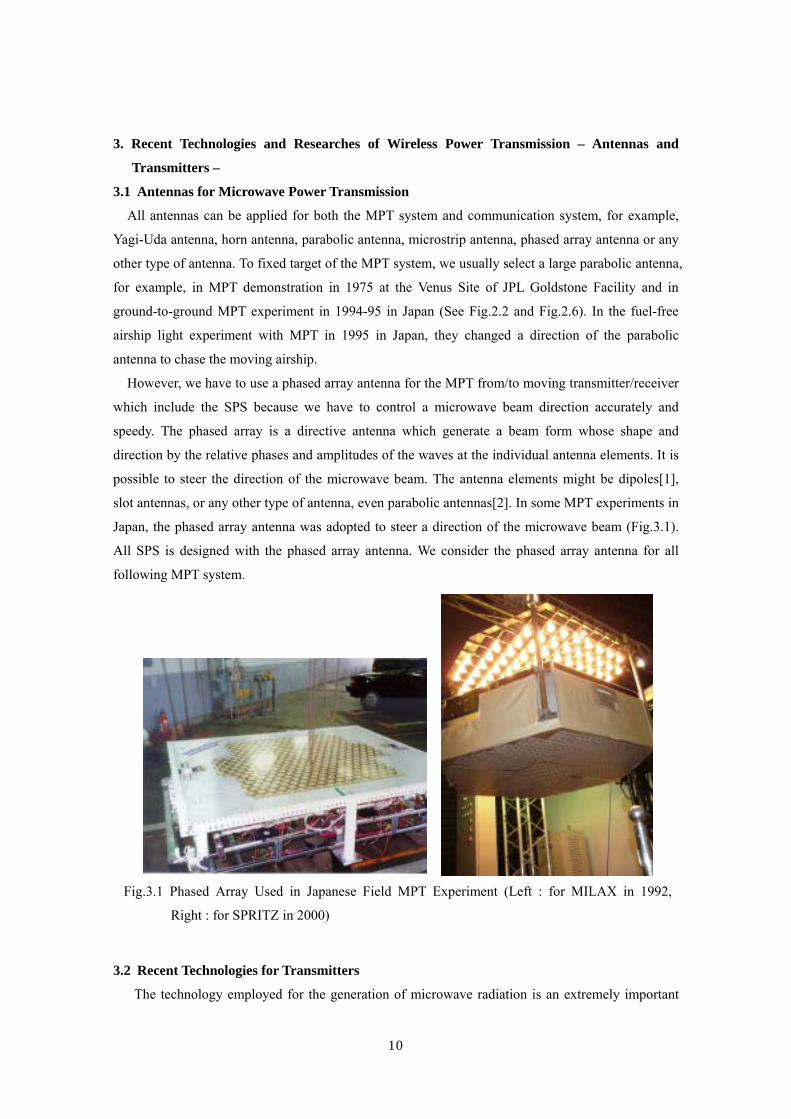
Japan, the phased array antenna was adopted to steer a direction of the microwave beam (Fig.3.1).
All SPS is designed with the phased array antenna. We consider the phased array antenna for all
following MPT system.
3.2 Recent Technologies for Transmitters
The technology employed for the generation of microwave radiation is an extremely important
Fig.3.1 Phased Array Used in Japanese Field MPT Experiment (Left : for MILAX in 1992,
Right : for SPRITZ in 2000)

11
subject for the MPT system. We need higher efficient generator/amplifier for the MPT system than
that for the wireless communication system. For highly efficient beam collection on rectenna array,
we need higher stabilized and accurate phase and amplitude of microwave when we use phased array
system for the MPT.
There are two types of microwave generators/amplifiers. One is a microwave tube and the other is a
semiconductor amplifier. Trew reviewed microwave generators/amplifiers, frequency vs. averaged
power as shown in Fig.3.1[2]. These have electric characteristics contrary to each other. The
microwave tube, such as a cooker-type magnetron, can generate and amplify high power microwave
(over kW) with a high voltage (over kV) imposed. Especially, magnetron is very economical. The
semiconductor amplifier generate low power microwave (below 100W) with a low voltage (below
fifteen volt) imposed. It is still expensive currently. Although there are some discussion concerning
generation/amplifier efficiency, the microwave tube has higher efficiency (over 70%) and the
semiconductor has lower efficiency (below 50%) in general. We have to choose tube/semiconductor
case by case for the MPT system.
3.2.1 Magnetron
Magnetron is a crossed field tube in which BErr
× forces electrons emitted from the cathode to take cyclonical path to the anode. The magnetron is self-oscillatory device in which the anode
contains a resonant RF structure. The magnetron has long history from invention by A. W. Hull in
1921. The practical and efficient magnetron tube gathered world interest only after K. Okabe
Fig. 3.1 Average RF output power versus frequency for various electronic devices[4] and
semiconductors[2]
12
proposed the divided anode-type magnetron in 1928. Magnetron technologies were advanced during
the World War II, especially in Japanese Army. The magnetrons main were advanced and
manufactured for the microwave ovens. As a result, the magnetron of 500 – 1,000 W is widely used
in microwave ovens in 2.45 GHz, and is a relatively inexpensive oscillator (below $5). There is a net
global capacity of 45.5GW/year for all magnetrons used in microwave ovens whose production is 50
– 55 millions. A history of the magnetron is a history of a microwave oven. The first microwave
oven with a magnetron sold shortly in U. S. A. after the World War II ended for more than $2,000,
the equivalent of about $20,000 today. In 1960’s, Japan played a important role to reduce the cost of
the microwave oven. Compared that American tube’s cost was $300 and they planned to sell for
$500 in 1960’s, Japanese tube cost was less than $25. In 1970, U.S. manufacturers sold 40,000 ovens
at $300 to $400 apiece, but by 1971 the Japanese had begun exporting low-cost models priced $100
to $200 less. Sales increased rapidly over the next 15 years, rising to a million by 1975 and 10
million by 1985, nearly all of them Japanese[5]. But history repeats itself. Instead of Japanese
microwave oven, Korean and Chinese more reduce the cost of the microwave oven now.
Therefore, the magnetron is suitable device for the MPT because of high efficiency and low cost
and unsuitable device because of its unstable frequency and uncontrollable phase. If we do not make
a phased array to control beam direction electrically, the magnetron can be applied for the MPT
system. However, the cooker-type magnetron itself cannot be applied for the phased array-type MPT
because it is only a generator and we cannot control/stabilize the phase and the amplitude. The
cooker-type magnetron was considered as noisy device. It is however confirmed that spurious
emissions from the cooker-type magnetron with a stable DC power supply is low enough and this
can be applied to the MPT system[6]. Peak levels of higher harmonics are below -60 dBc and other
spurious is below -100 dBc.
It was W. C. Brown who invented a voltage controlled oscillator with a cooker-type magnetron in
a phase locked loop[7]. He could control and stabilize a phase of microwave emitted from
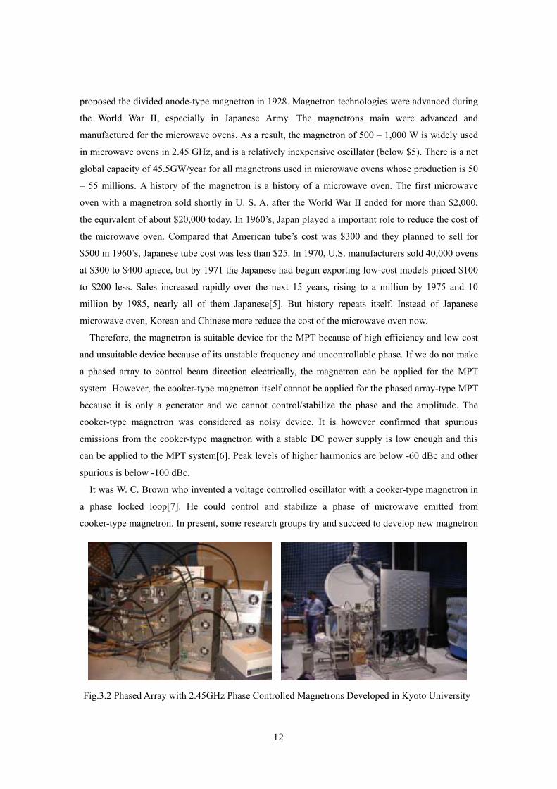
cooker-type magnetron. In present, some research groups try and succeed to develop new magnetron
Fig.3.2 Phased Array with 2.45GHz Phase Controlled Magnetrons Developed in Kyoto University
13
system which we can control and stabilize a phase of microwave emitted from cooker-type
magnetron[8]-[13]. In their developed magnetrons, an injection locking and PLL feedback are
adopted as same as that adopted in Brown’s work. The difference between the methods proposed in
these papers is how to control a phase of the magnetron. The Kyoto University’s system is most
stabilized. As an advanced method, a phase and amplitude controlled magnetron (PACM) has been
developed at Kyoto University, Japan[14]. They realized that the frequency stability and an error in
phase and amplitude of the PACM are below 10-6, within 1 degree, and within 1 %, respectively.
The technology of the PACM is effective to realize the economical MPT system with light weight
and high DC-RF conversion efficiency. They have also succeeded to control beam directions with
phased arrays with phase controlled magnetrons operated in 2.45 GHz and 5.8 GHz (Fig.3.2)[15].
3.2.2 Traveling Wave Tube Amplifier (TWTA)
Traveling Wave Tube (TWT) was invented by R. Kompfner in the World War II and was advanced
theoretically and improved by J. R. Pierce and L. M. Field in 1945. The TWT is a linear beam tube
with helix structure. The helix slow wave structure (SWS) slows the RF waves down to just below
the velocity of the electron beam. In
the TWT, the interaction between the
RF waves and the electron beam is
continuous along the length of the
SWS. The TWT can be used for
amplifier and we call it TWT
amplifier (TWTA). The longer the
tube, the higher gain. Applied
frequency of the TWTA is very wide,
from 1GHz-band to 60 GHz-band.
Typical output power of the TWT is
a few hundreds watts.
The TWTA is widely used in
television broadcasting satellites and
communication satellites. The
TWTA has a proven track record in
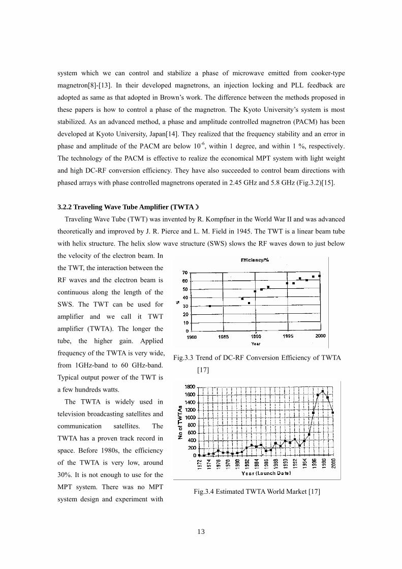
space. Before 1980s, the efficiency
of the TWTA is very low, around
30%. It is not enough to use for the
MPT system. There was no MPT
system design and experiment with
Fig.3.3 Trend of DC-RF Conversion Efficiency of TWTA
[17]
Fig.3.4 Estimated TWTA World Market [17]

14
TWTA. However, in recent
years, a TWTA uses
techniques called velocity
tapering energy recovery
[16]. In this way, the net
conversion rate has risen to
around 70 %[17] (Fig.3.3).
Market of the TWTA grows
from 1972 and the price of
the TWTA decreases (Fig.3.4, Fig.3.5)[17]. The paper [17] describes that main reasons for this price
decrease are (1) development time and effort could be reduced due to the standardization of the
product, (2) parts cost could be reduced due to buying higher number of parts and holding them on
stock, (3) manufacturing cost could be reduced by manufacturing larger number of TWTAs in a
certain time frame and by more automatization in the manufacturing process, and (4) test time and
effort has been reduced due to the higher credibility of the product.
Trends of development of the TWT are MPM (Microwave Power Module) and phased array TWT.
The MPM combines the best aspects of TWT, semiconductor amplifiers, and state-of-the-art power
supply technology into one package. This makes MPM into a good candidate for space application
because it has high conversion efficiency, small size and low weight. In near future, we may consider
the MPT system with TWTA.
3.2.3 Klystron
The klystron was invented by the Varian brothers in the late 1930s. The klystron is also a linear
beam tube with cavities. Electrons are emitted from the cathode and electron beam passes through
the cavities. When RF inputs from input cavity, the electron beam is modulated and RF is amplified
in last. The klystron is high power amplifier from tens of kilowatts to a few megawatts with high
efficiency, over 70%. It requires a ponderous power supply and also a heavy magnet. The klystrons
are used for broadcast applications in 400-850 MHz-band. The klystron is also used for uplinks
(earth stations beaming to orbital satellites). The other application of the klystron is fusion.
The klystron was used in MPT demonstration in 1975 at the Venus Site of JPL Goldstone Facility.
One klystron transmitted microwave of 450 kW and 2.388 GHz. The klystron is suitable for large
MPT system such as SPS. The SPS designed by NASA/DOE in 1980 was designed with phased
array of the klystrons. However, there has not been klystron phased array system yet.
Detail general theory of the microwave tubes is described in reference [18].
Fig.3.5 Trend of Price of TWTA (% ; 1996=100%) [17]

15
3.2.4 Semiconductor Amplifier
After 1980s, semiconductor device plays the lead in microwave world instead of the microwave
tubes. It causes by advance of mobile phone network. The semiconductor device is expected to
expand microwave applications, for instance, phased array and Active integrated antenna (AIA),
because of its manageability and mass productivity. After 1990s, some MPT experiments were
carried out in Japan with phased array of semiconductor amplifiers[19].
Typical semiconductor device for microwave circuits are FET (Field Effect Transistor), HBT
(Heterojunction Bipolar Transistor), and HEMT (High Electron Mobility Transistor). Present
materials for the semiconductor device are Si for lower frequency below a few GHz and GaAs for
higher frequency. We design microwave circuits with these semiconductor devices. It is easy to
control a phase and amplitude through the microwave circuits with semiconductor devices, for
example, amplifiers, phase shifters, modulators, and so on. For the microwave amplifiers, circuit
design theoretically determines efficiency and gain. A, B, C class amplifiers are classified in bias
voltage in device. These classes are also applied in kHz systems. In D, E, F class amplifiers for
microwave frequency, higher harmonics are used effectively to increase efficiency, theoretically
100%. Especially F class amplifier is expected as high efficient amplifier for the MPT system.
We always have to consider the efficiency. Some reports noted that it is possible to realize a PAE (power added efficiency = (Pout-Pin)/PDC) of 54%, efficiency of about 60%, at 5.8GHz. These are
champion data in laboratory. To develop the high efficient amplifier, we need strict adjustment in
contrary of mass productivity. It causes that the semiconductor amplifiers keep expensive cost for
the MPT system. It potentially has low price capability by the mass production. An efficiency of a
driver stage is also taken into consideration if the gain of the final stage is not enough.
The other requirement from MPT use to the semiconductor amplifier is linearity of amplifier
because power level of the MPT is much higher than that for wireless communication system and we
have to suppress unexpected spurious radiation to reduce interference. The maximum efficiency
usually is realized at saturated bias voltage. It does not guarantee the linearity between input and
output microwaves and non-linearity causes high spurious which must be suppressed in the MPT.
Therefore, dissolution of tortuous relationship between efficiency and linearity is expected by the
MPT.
There are unique development items for the SPS from the microwave point of view distinguished
from the ordinary use of the microwave technology such as telecommunications. These three points
may be described as 1) pureness in spectrum, 2) high power and high efficient power generation and
high efficient detector in a small and light fashion, and 3) precise beam control for a large phased
array antenna combining with a huge number of sub-arrays.
To cope with the second requirement for the microwave technology, the large plate model by a
layered configuration in a sandwich fashion was proposed. The point of this configuration is the
16
effective integration with DC power generation, microwave circuit operation and radiation, and their
control. As one of the promising microwave technologies, the “the Active Integrated Antenna
(AIA)” technique is considered. The AIA is defined as the single entity consisting of an integrated
circuit and a planar antenna. The AIA has many features applicable to the SPS. Due to the nature
of small-size, thinness, lightness and multi-functions in AIA, a power transmission part of the
spacetenna (space antenna) can be realized in thin structure. Prof. Kawasaki’s group have developed
some AIA system for the MPT application[20].
In present, new materials are developed fore the semiconductor device to increased output power
and efficiency. They are called wide-bandgap devices such as SiC and GaN. The wide-bandgap
devices can make over hundreds watt amplifier with one chip. In recent days, there are some
development of microwave amplifiers with SiC MESFET[21][22] or GaN HEMT[23][24]. The other
trend is development of MMIC (Microwave Monolithic Integrated Circuit) to reduce space and
weight, especially for mobile applications. Lighter transmitters can be realized with the MMIC
devices. The MMIC devices still have heat-release problems, poor efficiency, and low power output.
However, it is expected that the technical problems will be solved by efforts of many engineers.
3.3 Transmitter Issues and Answers for Space Use
Largest MPT application is a SPS in which over GW microwave will be transmitted from space to
ground at distance of 36,000km. In the SPS, we will use microwave transmitters in space. For space
use, the microwave transmitter will be required lightness to reduce launch cost and higher efficiency
to reduce heat problem.
A weight of the microwave tube is lighter than that of the semiconductor amplifier when we
compare the weight by power-weight ratio (kg/kW). The microwave tube can generate/amplify
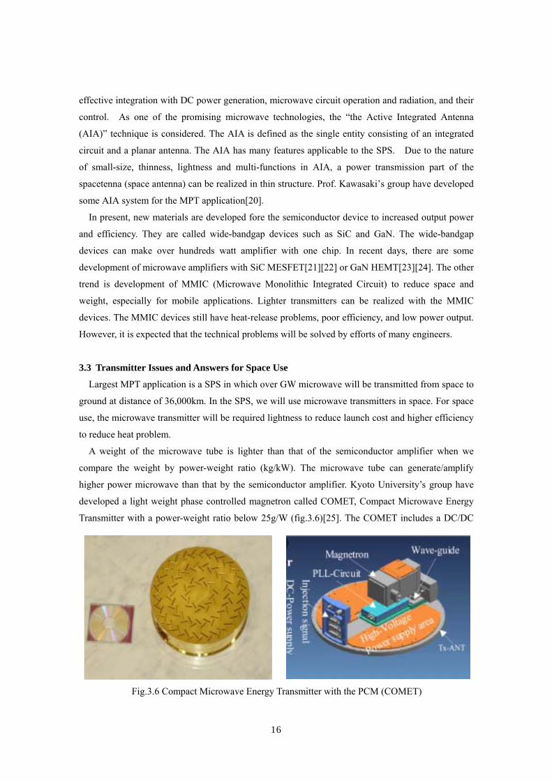
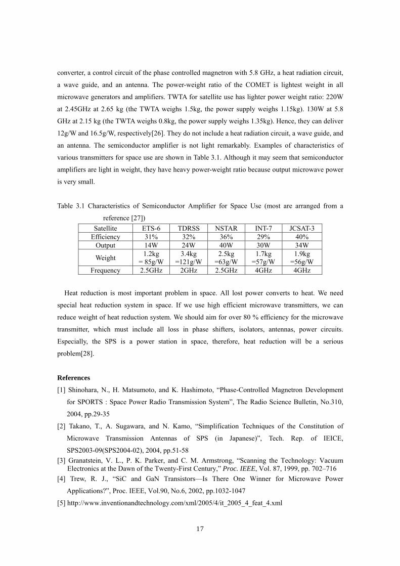
higher power microwave than that by the semiconductor amplifier. Kyoto University’s group have
developed a light weight phase controlled magnetron called COMET, Compact Microwave Energy
Transmitter with a power-weight ratio below 25g/W (fig.3.6)[25]. The COMET includes a DC/DC
Fig.3.6 Compact Microwave Energy Transmitter with the PCM (COMET)
17
converter, a control circuit of the phase controlled magnetron with 5.8 GHz, a heat radiation circuit,
a wave guide, and an antenna. The power-weight ratio of the COMET is lightest weight in all
microwave generators and amplifiers. TWTA for satellite use has lighter power weight ratio: 220W
at 2.45GHz at 2.65 kg (the TWTA weighs 1.5kg, the power supply weighs 1.15kg). 130W at 5.8
GHz at 2.15 kg (the TWTA weighs 0.8kg, the power supply weighs 1.35kg). Hence, they can deliver
12g/W and 16.5g/W, respectively[26]. They do not include a heat radiation circuit, a wave guide, and
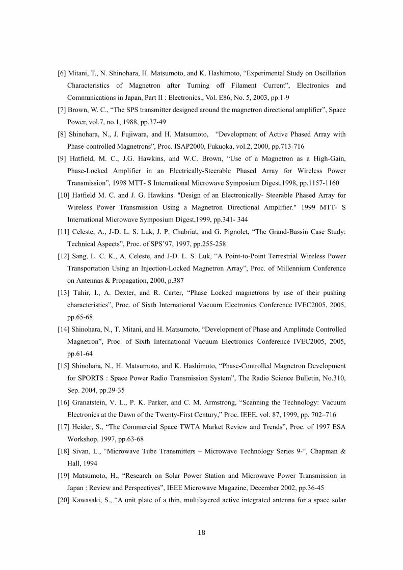
an antenna. The semiconductor amplifier is not light remarkably. Examples of characteristics of
various transmitters for space use are shown in Table 3.1. Although it may seem that semiconductor
amplifiers are light in weight, they have heavy power-weight ratio because output microwave power
is very small.
Table 3.1 Characteristics of Semiconductor Amplifier for Space Use (most are arranged from a
reference [27]) Satellite ETS-6 TDRSS NSTAR INT-7 JCSAT-3
Efficiency 31% 32% 36% 29% 40% Output 14W 24W 40W 30W 34W
Weight 1.2kg = 85g/W
3.4kg =121g/W
2.5kg =63g/W
1.7kg =57g/W
1.9kg =56g/W
Frequency 2.5GHz 2GHz 2.5GHz 4GHz 4GHz
Heat reduction is most important problem in space. All lost power converts to heat. We need
special heat reduction system in space. If we use high efficient microwave transmitters, we can
reduce weight of heat reduction system. We should aim for over 80 % efficiency for the microwave
transmitter, which must include all loss in phase shifters, isolators, antennas, power circuits.
Especially, the SPS is a power station in space, therefore, heat reduction will be a serious
problem[28].
References
[1] Shinohara, N., H. Matsumoto, and K. Hashimoto, “Phase-Controlled Magnetron Development
for SPORTS : Space Power Radio Transmission System”, The Radio Science Bulletin, No.310,
2004, pp.29-35
[2] Takano, T., A. Sugawara, and N. Kamo, “Simplification Techniques of the Constitution of
Microwave Transmission Antennas of SPS (in Japanese)”, Tech. Rep. of IEICE,
SPS2003-09(SPS2004-02), 2004, pp.51-58 [3] Granatstein, V. L., P. K. Parker, and C. M. Armstrong, “Scanning the Technology: Vacuum
Electronics at the Dawn of the Twenty-First Century,” Proc. IEEE, Vol. 87, 1999, pp. 702–716 [4] Trew, R. J., “SiC and GaN Transistors—Is There One Winner for Microwave Power
Applications?”, Proc. IEEE, Vol.90, No.6, 2002, pp.1032-1047
[5] http://www.inventionandtechnology.com/xml/2005/4/it_2005_4_feat_4.xml
18
[6] Mitani, T., N. Shinohara, H. Matsumoto, and K. Hashimoto, “Experimental Study on Oscillation
Characteristics of Magnetron after Turning off Filament Current”, Electronics and
Communications in Japan, Part II : Electronics., Vol. E86, No. 5, 2003, pp.1-9
[7] Brown, W. C., “The SPS transmitter designed around the magnetron directional amplifier”, Space
Power, vol.7, no.1, 1988, pp.37-49
[8] Shinohara, N., J. Fujiwara, and H. Matsumoto, “Development of Active Phased Array with
Phase-controlled Magnetrons”, Proc. ISAP2000, Fukuoka, vol.2, 2000, pp.713-716
[9] Hatfield, M. C., J.G. Hawkins, and W.C. Brown, “Use of a Magnetron as a High-Gain,
Phase-Locked Amplifier in an Electrically-Steerable Phased Array for Wireless Power
Transmission”, 1998 MTT- S International Microwave Symposium Digest,1998, pp.1157-1160
[10] Hatfield M. C. and J. G. Hawkins. "Design of an Electronically- Steerable Phased Array for
Wireless Power Transmission Using a Magnetron Directional Amplifier." 1999 MTT- S
International Microwave Symposium Digest,1999, pp.341- 344
[11] Celeste, A., J-D. L. S. Luk, J. P. Chabriat, and G. Pignolet, “The Grand-Bassin Case Study:
Technical Aspects”, Proc. of SPS’97, 1997, pp.255-258
[12] Sang, L. C. K., A. Celeste, and J-D. L. S. Luk, “A Point-to-Point Terrestrial Wireless Power
Transportation Using an Injection-Locked Magnetron Array”, Proc. of Millennium Conference
on Antennas & Propagation, 2000, p.387
[13] Tahir, I., A. Dexter, and R. Carter, “Phase Locked magnetrons by use of their pushing
characteristics”, Proc. of Sixth International Vacuum Electronics Conference IVEC2005, 2005,
pp.65-68
[14] Shinohara, N., T. Mitani, and H. Matsumoto, “Development of Phase and Amplitude Controlled
Magnetron”, Proc. of Sixth International Vacuum Electronics Conference IVEC2005, 2005,
pp.61-64
[15] Shinohara, N., H. Matsumoto, and K. Hashimoto, “Phase-Controlled Magnetron Development
for SPORTS : Space Power Radio Transmission System”, The Radio Science Bulletin, No.310,
Sep. 2004, pp.29-35
[16] Granatstein, V. L., P. K. Parker, and C. M. Armstrong, “Scanning the Technology: Vacuum
Electronics at the Dawn of the Twenty-First Century,” Proc. IEEE, vol. 87, 1999, pp. 702–716
[17] Heider, S., “The Commercial Space TWTA Market Review and Trends”, Proc. of 1997 ESA
Workshop, 1997, pp.63-68
[18] Sivan, L., “Microwave Tube Transmitters – Microwave Technology Series 9-“, Chapman &
Hall, 1994
[19] Matsumoto, H., “Research on Solar Power Station and Microwave Power Transmission in
Japan : Review and Perspectives”, IEEE Microwave Magazine, December 2002, pp.36-45
[20] Kawasaki, S., “A unit plate of a thin, multilayered active integrated antenna for a space solar
19
power system”, The Radio Science Bulletin, No.310, 2004, pp.15-22
[21] Sayed, A., S. von der Mark and G. Boeck, “An Ultra Wideband 5 W Power Amplifier Using
SiC MESFETs”, Proc. of 12th GAAS Symposium, 2004, pp.455-458
[22] Milligan, J. M., J. Henning, S.T. Allen, A.Ward, P. Parikh, R.P. Smith, A. Saxler, Y. Wu, and J.
Palmour, “Transition of SiC MESFET Technology from Discrete Transistors to High
Performance MMIC Technology”, http://www.lehighton.com/AppNotes/creepaper.pdf
[23] Chung, Y., C. Y. Hang, S. Cai, Y. Qian, C. P. Wen, K. L. Wang, and T. Itoh,” AlGaN/GaN
HFET Power Amplifier Integrated With Microstrip Antenna for RF Front-End Applications”,
IEEE Trans. MTT, Vol.51, No.2, 2003, pp.653-659
[24] Xu, H., C. Sanabria, A. Chini, S. Keller, U. K. Mishra, and R. A. York, “A C-Band
High-Dynamic Range GaN HEMT Low-Noise Amplifier”, IEEE Microwave and Wireless
Componets Lett., Vol.14, No.6, 2004, pp.262-264
[25] Fujiwara, E., Y. Takahashi, N. Tanaka, K. Saga, K. Tsujimoto, N. Shinohara, and H. Matsumoto,
“Compact Microwave Energy Transmitter (COMET)”, Proc. of Japan-US Joint Workshop on
SSPS (JUSPS), 2003, pp.183-185
[26] Katakami, K., “Review of Performance Improvement and Development Trends (in Japanese)”,
Tech. Report of IEICE, SPS2003-03(2004-02), pp.15-22, 2004
[27] Kitazawa, S., “Commercialization of the on-Board Equipments for Communications Satellites
in Japan”, Proc. of MWE’96 Microwave Workshop Digest[WS14-3], 1996, pp.387-395
[28] Ohta, H., H. Kawasaki, S. Tpyama, M. Mori, S. Hirai, S. Saito, N. Morita, T. Ohno, M.
Higashijima, and Y. Shinmoto, “A Study on the Feasibility of Heat Transfer and Transport from
Generator/Transmitter Combined Units of Assumed 10 MW Space Solar Power System”, Proc.
of 4th International Conference on Solar Power from Space (SPS’04), 2004, pp.257-262
20
4. Recent Technologies and Researches of Wireless Power Transmission – Beam Control ,
Target Detection, Propagation –
4.1 Recent Technologies of Retrodirective Beam Control
A microwave power transmission is suitable for a power transmission from/to moving
transmitters/targets. Therefore, accurate target detection and high efficient beam forming are
important. Retrodirective system is always used for SPS.
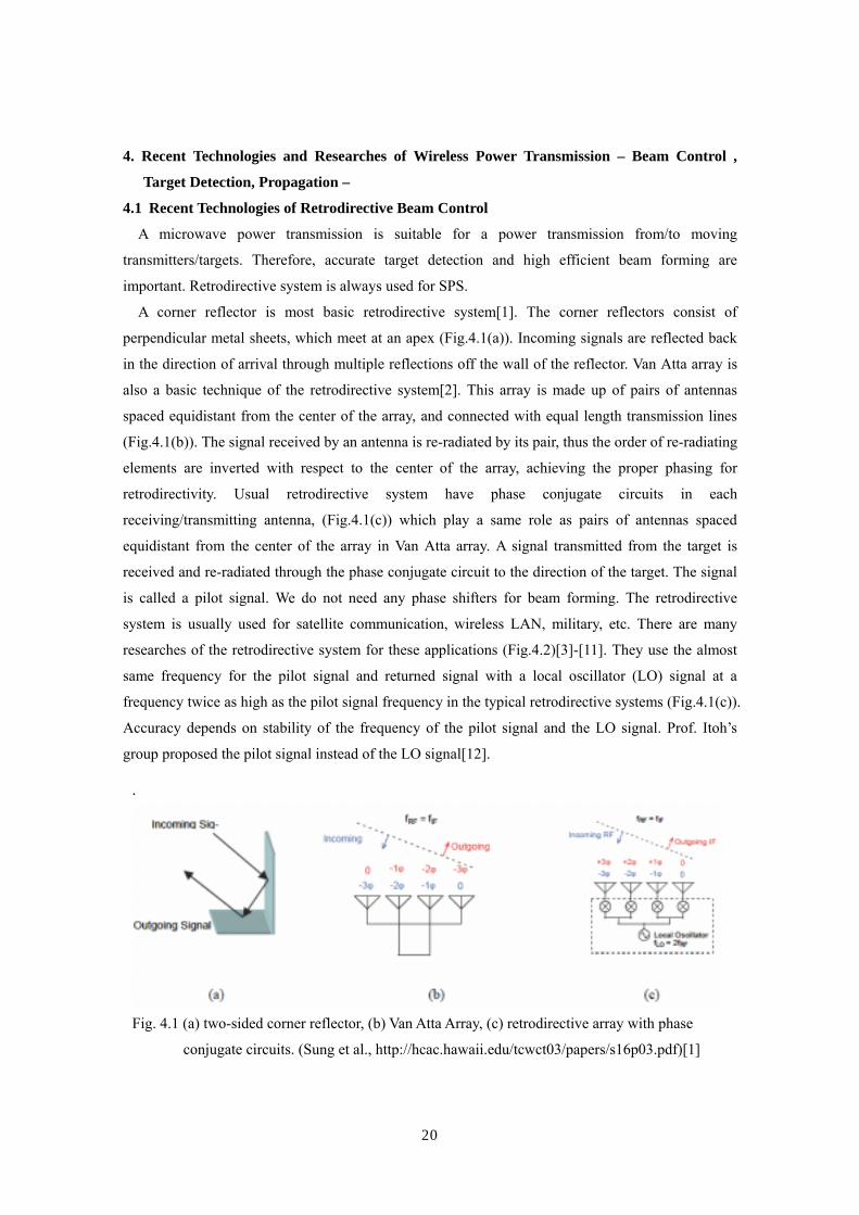
A corner reflector is most basic retrodirective system[1]. The corner reflectors consist of
perpendicular metal sheets, which meet at an apex (Fig.4.1(a)). Incoming signals are reflected back
in the direction of arrival through multiple reflections off the wall of the reflector. Van Atta array is
also a basic technique of the retrodirective system[2]. This array is made up of pairs of antennas
spaced equidistant from the center of the array, and connected with equal length transmission lines
(Fig.4.1(b)). The signal received by an antenna is re-radiated by its pair, thus the order of re-radiating
elements are inverted with respect to the center of the array, achieving the proper phasing for
retrodirectivity. Usual retrodirective system have phase conjugate circuits in each
receiving/transmitting antenna, (Fig.4.1(c)) which play a same role as pairs of antennas spaced
equidistant from the center of the array in Van Atta array. A signal transmitted from the target is
received and re-radiated through the phase conjugate circuit to the direction of the target. The signal
is called a pilot signal. We do not need any phase shifters for beam forming. The retrodirective
system is usually used for satellite communication, wireless LAN, military, etc. There are many
researches of the retrodirective system for these applications (Fig.4.2)[3]-[11]. They use the almost
same frequency for the pilot signal and returned signal with a local oscillator (LO) signal at a
frequency twice as high as the pilot signal frequency in the typical retrodirective systems (Fig.4.1(c)).
Accuracy depends on stability of the frequency of the pilot signal and the LO signal. Prof. Itoh’s
group proposed the pilot signal instead of the LO signal[12].
.
Fig. 4.1 (a) two-sided corner reflector, (b) Van Atta Array, (c) retrodirective array with phase
conjugate circuits. (Sung et al., http://hcac.hawaii.edu/tcwct03/papers/s16p03.pdf)[1]

21
There are other kinds of the phase conjugate circuits for the MPT applications. Kyoto University’s
group have developed a retrodirective system with asymmetric two pilot signals, ωt+∆ω and ωt+2∆ω,
and the LO signal of 2ωt[13]. ωt indicate a frequency of a transmitter. They have also developed the
(a) (b)
(c) (d)
(e) (f)
Fig.4.2 Various Retrodirective Array with Phase Conjugate Circuits Developed in
(a) Kyoto University and Kobe University in 1987 (2.45GHz)[13], (b) Kyoto University
in 1996 (2.45GHz)[13], (c) Queen’s University (62-66GHz)[8], (d) Jet Propulsion
Laboratory and University of Michigan in 2001 (5.9GHz)[11], (e) UCLA in 1995
(6GHz)[5], (f) UCLA in 2000 (6GHz)[3]

22
other retrodirective system with 1/3 ωt pilot signal and without LO signal. The LO signal is
generated from the pilot signals. The latter system solve a fluctuation problem of the LO and the
pilot signal which cause phase errors because the fluctuations of the LO and the pilot signals are
synchronous. They have used 2.45 GHz for ωt. Mitsubishi Electric Corporation in Japan have
developed PLL-heterodyne type retrodirective system in which different frequencies for the pilot
signal and the microwave power beam, 3.85 GHz and 5.77 GHz, respectively, have been used[14].
The retrodirective system unifies target detection with beam forming by the phase conjugate
circuits. There are some methods for target detecting with pilot signal which is separated to beam
forming. We call the method “software retrodirective”. Computer is usually used for the software
rectodirective with the phase data from a pilot signal and for the beam forming with calculation of
the optimum phase and amplitude distribution on the array. In the software rectodirective, we can
form microwave beam freely, for example, multi-beams. On contrary, we need phase shifters in all
antennas.
After the target detection, we need accurate beam forming. For the optimum beam forming, there
are some algorism, for instance, neural network, genetic algorithm, and multi-objective optimization
learning. The “optimum” has multi-meanings, to suppress sidelobe level, to increase beam collection
efficiency, and to make multiple power beams. We can select object of optimum and algorism freely
with consideration of time of calculation.
Kyoto University in Japan and Texas A&M University in USA have developed the software
retrodirective system independently[16][17]. Kyoto University’s group use a pilot signal modulated
by spread spectrum in order to use the same frequency band of microwave power beam and the pilot
signal and also in order to use two or more pilot signals for multi-target MPT[16].
A standard of the phase/frequency is very important to steer microwave power beam to a desired
direction Both for beam forming with the software retrodirective and for retrodirective with the
phase conjugate circuit. If the standard of the phase/frequency like the LO signal is different on one
array, we cannot form the microwave beam to the desired direction. Although the best way is to use
only one oscillator for the standard of the phase/frequency for one phased array of larger than km in
size with more than billion elements, it is quite difficult. A better way is use of some oscillators on
some group of sub-phased array and the oscillators are synchronous with each other. Some trials
have been carried out. One is wireless synchronization of separated units. The present accuracy of
wireless synchronization is below 0.6 ppm of the frequency and below 3.5 degree of phase error[18].
The other is self-synchronization with some data sent from the target[19]. In this method, a phase of
a part of arrays is changed and a resultant change of the microwave beam intensity is measured in
the rectenna site. The change gives us information on phase corrections.

23
4.2 Environmental Issues
4.2.1 Interferences to Existent Wireless System
Most MPT system adopted 2.45 GHz or 5.8 GHz band which are allocated in the ITU-R Radio
Regulations to a number of radio services and are also designated for ISM (Industry, Science and
Medical) applications. Conversely speaking, there is no allowed frequency band for the MPT,
therefore, we used the ISM band. The bandwidth of the microwave for the MPT do not need wide
band and it is enough quite narrow since an essentially monochromatic wave is used without
modulation because we use only carrier of the microwave as energy. Power density for the MPT is a
few orders higher than that for the wireless communication. We have to consider and dissolve
interferences between the MPT to the wireless communication systems.
One calculation of the interferences between the MPT of the SPS, mainly 2.45 GHz, to the wireless
communication systems was done in Japan[20]. If the harmonics of the MPT frequencies are, however,
regulated by the ITU (International Telecommunication Union) power flux density (PFD) limits, some
modulation might be necessary. Carrier noises, harmonics, and spurious emissions of the MPT signal
should be quite small to avoid interference to other radio services in operation around the world.
Grating lobes and sidelobes of the MPT beam should be low enough in order to make the affected
region as small as possible. Also, grating lobes should be mitigated because they are a direct loss of
transmitter power.
The other interference assessment on 2.45 GHz and 5.8 GHz MPT of the SPS was published in
Japan[21]. They discussed mainly Japanese case. They discussed four main existent systems, terrestrial
radio relay links on 5GHz (5G-150M) system and 11GHz (11G-50M) system, radars called ARSR
(air route surveillance radar, 1.3-1.35 GHz), ASR (airport surveillance radar, 2.7-2.9GHz) and MR
(meteorological radar, 5.25 - 5.35GHz), Space-to-Earth communications on 11-12 GHz-band, and
applications in the ISM bands, wireless LAN and DSRC (Dedicated Short Range Communication).
JAXA (Japanese Aerospace Exploration Agency) estimated the interference and submitted
“Proposal of the extension regarding the termination year of Question ITU-R 210/1 to 2010 from
2005”to ITU in 2004[22], and will submit in 2005. Responses to Question ITU-R 210/1 (1997) had
been submitted to the ITU-R WP1A meetings by USA. Since the response (Document 1A/18-E,
which was incorporated into Document 1A/32-E Annex8) in October 2000 [23], no response has
been submitted. As the studies for this Question had not been completed by 2002, the date has been
extended by three years. They submit the above document from JAXA in response to Question 210/1
which would otherwise terminate this year, to extend the Question.
4.2.2 Safety on Ground
One of the characteristics of the MPT is to use more intense microwave than that in wireless
communication systems. Therefore, we have to consider MPT safety for human. In recent years there
24
have been considerable discussions and concerns about the possible effect for human health by RF
and MW radiation. Especially, there have been many research and discussions about effects at 50/60
Hz and over GHz (microwave). These two effects are different.
There is long history concerning the safety of the microwave[24]. Contemporary RF/microwave
standards are based on the results of critical evaluations and interpretations of the relevant scientific
literature. The SAR (specific absorption rate) threshold for the most sensitive effect considered
potentially harmful to humans, regardless of the nature of the interaction mechanism, is used as the
basis of the standard. The SAR is only heating problem. The scientific research results have
indicated that the microwave effect to human health is only heating problem. This is different from
the EMF research. Famous guideline, the ICNIRP (International Commission on Non-Ionizing
Radiation Protection) guidelines, are 50 or 10 W/m2 for occupationally exposed vs. the general
public, at either frequency[25]. The corresponding limits for IEEE standards for maximum
permissible human exposure to microwave radiation, at 2.45 or 5.8 GHz, are 81.6 or 100 W/m2 as
averaged over six min, and 16.3 or 38.7 W/m2 as averaged over 30 min, respectively, for controlled
and uncontrolled environments[26]. The controlled and uncontrolled situations are distinguished by
whether the exposure takes place with or without knowledge of the exposed individual, and is
normally interpreted to mean individuals who are occupationally exposed to the microwave radiation,
as contrasted with the general public. In future MPT system, we have to keep the safety guideline
outside of a rectenna site. Inside the rectenna site, there remains discussion concerning the keep out
area, controlled or uncontrolled area.
4.2.3 Interaction with Atmosphere
In general, effect of atmosphere to microwave is quite small. There are absorption and scatter by
air, rain, and irregularity of air refraction ratio. In 2.45 GHz and 5.8 GHz, the absorption by water
vapor and oxygen dominate the effect in the air. Especially, it is enough to consider only absorption
by the oxygen in the microwave frequency. It is approximately 0.007 dB/km[27]. In the SPS case,
the amount of total absorption through the air from space is approximately 0.035 dB[28]. When
elevation is 47 degree in the middle latitude, for example, in Japan, the total absorption is
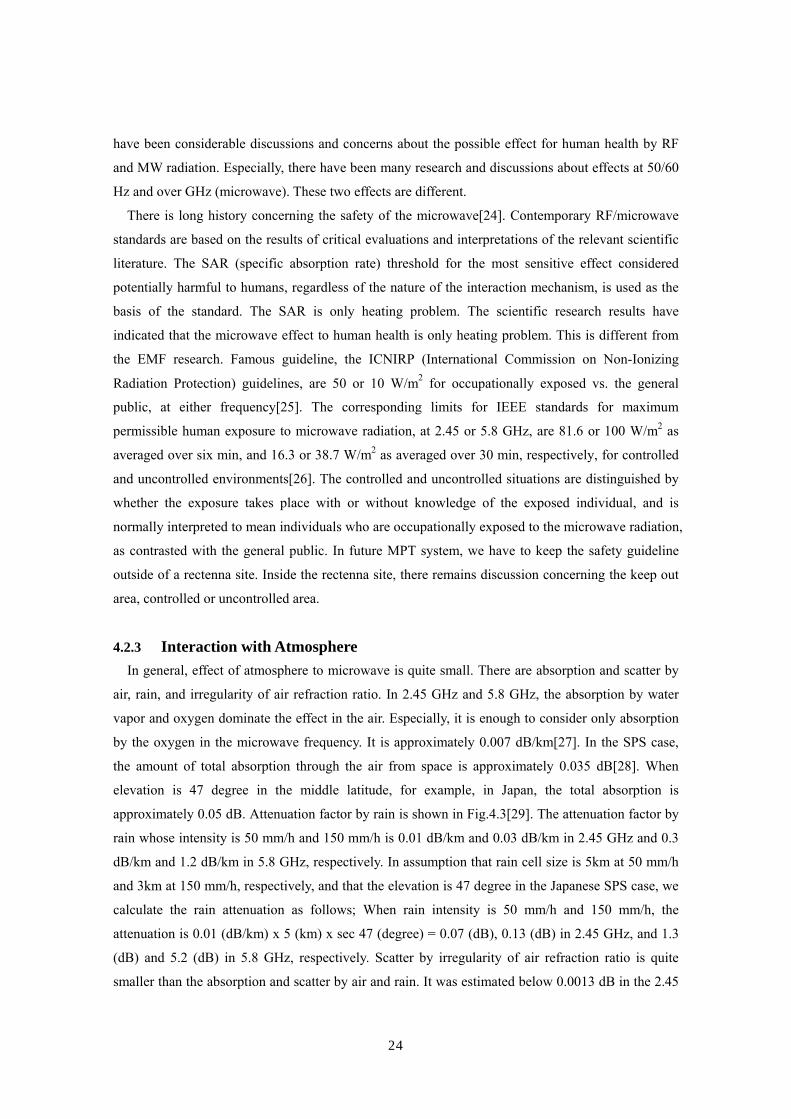
approximately 0.05 dB. Attenuation factor by rain is shown in Fig.4.3[29]. The attenuation factor by
rain whose intensity is 50 mm/h and 150 mm/h is 0.01 dB/km and 0.03 dB/km in 2.45 GHz and 0.3
dB/km and 1.2 dB/km in 5.8 GHz, respectively. In assumption that rain cell size is 5km at 50 mm/h
and 3km at 150 mm/h, respectively, and that the elevation is 47 degree in the Japanese SPS case, we
calculate the rain attenuation as follows; When rain intensity is 50 mm/h and 150 mm/h, the
attenuation is 0.01 (dB/km) x 5 (km) x sec 47 (degree) = 0.07 (dB), 0.13 (dB) in 2.45 GHz, and 1.3
(dB) and 5.2 (dB) in 5.8 GHz, respectively. Scatter by irregularity of air refraction ratio is quite
smaller than the absorption and scatter by air and rain. It was estimated below 0.0013 dB in the 2.45
25
GHz SPS[30]. Total attenuation of
the 2.45 GHz SPS is 0.05 + 0.13 +
0.0013 = 0.1813 dB. Total
attenuation of the 5.8 GHz SPS is
over 5 dB in hard rain
circumstance. In the 2.45 GHz
SPS, we can neglect the
attenuation by air and rain. We
have to consider a counterplan the
attenuation by rain in the 5.8 GHz
SPS.
4.2.4 Interaction with Space Plasmas
When microwave from the SPS
propagates through ionospheric
plasmas, some interaction between
the microwave and the ionospheric plasmas occurs. It is well known that refraction, Faraday rotation,
scintillation, and absorption occur between weak microwave used for satellite communication and
the plasmas. However, influence to the MPT system is negligible. For example, reflection through
the ionosphere at 2.45 GHz and 5.8 GHz is only 0.67 m and 0.12 m, respectively, when they
calculated theoretically with the Snell's law and total electron contents in the ionosphere[31].
However, there is no inference because diameter of rectenna site will be over km. Although plane
of polarization will rotate in approximately 7 degree at 2.45 GHz by Faraday rotation[32], there is
also no inference because we will use circular polarized microwave for the MPT of the SPS.
It is nonlinear interaction between intense microwave and the space plasmas that we have to
investigate before the commercial SPS. We theoretically predict that it has possibility to occur
Ohmic heating of the plasmas, plasma hall effect by Ponderomotive force, thermal self-focusing
effect of the microwave beam, and three-wave interactions and excitation of electrostatic waves in
MHz bands. These interactions will not occur in existent satellite communication systems because
the microwave power is very weak.
Perkins and Roble theoretically calculated the Ohmic heating by the microwave beam from the
SPS in 1978[33]. The absorption of the radio waves can be calculated from the electron density and
electron-neutral collision frequency profile. The effect is largest in the lower ionosphere (D and E
regions) where the collision frequency is highest. The NASA/DOE SPS was designed including the
results of the reference [34] and they decided that maximum microwave power density was 23 mW/
Fig.4.3 Attenuation factor by rain [28]
26
cm2 at the center of the rectenna site.
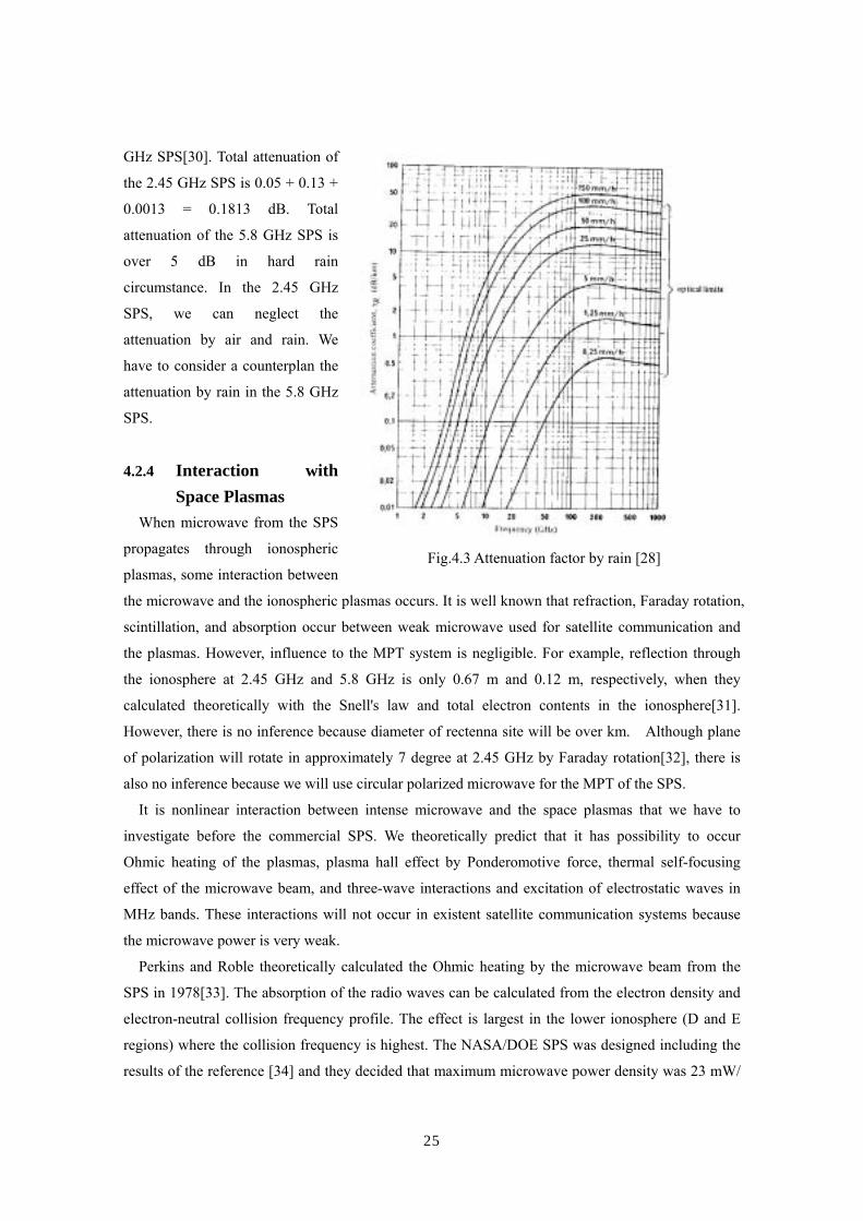
Concerning the three-wave interactions and excitation of electrostatic waves in MHz bands,
Matsumoto predicted in 1982 that the microwaves may decay into forward traveling electron plasma
waves (Raman scattering) or ion acoustic waves (Brillouin scattering) and a backward traveling
secondary microwave[35]. The electron plasma waves could be Langmuir waves when the excitation
is parallel to the geomagnetic field, or electron cyclotron waves for excitation perpendicular to the
field. These frequencies are typically 2-10 MHz in the local ionospheric plasma. Matsumoto’s group
carried out the first rocket MPT experiment called MINIX (Microwave Ionosphere Nonlinear
Interaction eXperiment) in 1983 in order to observe the excitation of the plasma waves
(Fig.4.4)[36][37][38]. It was found that the excited waves differed from the initial theoretical
expectations [39] in that the line spectrum expected from a simple three-wave coupling theory was
in fact a broad spectrum, and the electron cyclotron harmonics were stronger than the Langmuir
waves. Both these features could be successfully modeled using a more realistic computer
simulation[40] where the nonlinear feedback processes were fully incorporated. From these
simulation results it was estimated that below 0.01 % of the microwave beam energy from the SPS
would be converted to electrostatic waves.
Shklyar and Shinohara derived a equation of self-focusing effect of the microwave beam caused
by the inhomogeneity of the microwave energy density in 1992[41]. It occurs without the collisional
plasma heating. They neglected collisions and based the analysis on kinetic equation in collision free
plasma. Though the wave frequency is six orders of magnitude higher than the maximum collision
Fig.4.4 Observed Wave Spectrum Concerning Three-wave Interactions and Excitation of
Electrostatic Waves by Microwave in MINIX Rocket Experiment [36]

27
frequency in the ionosphere, the assumption of collisionless plasma is not obvious, since finally they
deal with a weak effect of Ponderomotive force. They showed this self-focusing effect will not occur
with the SPS and ionopheric parameters, the density and the temperature of the plasmas, the
frequency and the intensity of the microwave and its spatial gradient.
Plasma hall effect is predicted theoretically with Ponderomotive force and it is important to
consider the effect from the microwave beam to plasma circumstance. However, there have not been
advance of the research yet. Japanese group just start computer simulation with electromagnetic
particle code from 2004.
Almost all studies are theoretical prediction and computer simulations. There are only two
experimental data concerning the interaction between the intense microwave and the space plasmas.
Both experiments were carried out in Japan with small rockets[42]. We need advanced space
experiment to verify the theoretical studies as soon as possible.
References
[1] Sung, S. S., J. D. Roque, B. T. Murakami, G. S. Shiroma, R. Y. Miyamoto, and W. A. Shiroma,
“Retrodirective Antenna Technology for CubeSat Networks”, IEEE Topical Conference on
Wireless Communication Technology, 2003, pp. 220 - 221, Hawaii, U.S.A., 15-17, Oct. 2003
[2] Van Atta, L. G., “Electromagnetic Reflector”, U. S. patent No. 2,908,002; Oct. 6, 1959.
[3] Miyamoto, R. Y., Y. Qian, and T. Itoh, “An active integrated retrodirective transponder for remote
information retrieval-on-demand”, IEEE Trans. MTT, Vol.49, No.9, 2001, pp.1658-1662
[4] Leong, K. M. K. H., Y. Wang, and T. Itoh, “A Full Duplex Capable Retrodirective Array System
for High-Speed Beam Tracking and Pointing Applications”, IEEE Trans. MTT, Vol.52, No.5,
2004, pp.1479-1489
[5] Qian, Y., and T. Itoh, “Progress in Active Integrated Antennas and Their Applications”, IEEE
Trans. MTT, vol.46, no.11, 1998, pp.1891-1990
[6] Brabetz, T., V. F. Fusco, and S. Karode, “Balanced Subharmonic Mixers for Retrodirective-
Array Applications”, IEEE Trans. MTT, Vol.49, No.3, 2001, pp.465-469
[7] Karode, S. and V. F. Fusco, “Retro-Transceiver Array Using Monopole Antennas”, IEEE Trans.
MTT, Vol.49, No.3, 2001, pp.565-568
[8] http://www.ee.qub.ac.uk/hfe/st173.htm
[9] Gallop, J., D. Peden, L. Hao and J. Macfarlane, “A Microwave Phase Conjugating Antenna
Using High Temperature Superconductors”, Supercond. Sci. Technol. Vol.16, 2003,
pp.1566–1569
[10] Chang, Y., H. R. Fetterman, I. L. Newberg, and S. K. Panaretos, “Microwave Phase
Conjugation Using Antenna Arrays”, IEEE Trans. MTT, Vol.46, No.11, 1998, pp.1910-1919
[11] DiDomenico, L. D. and G. M. Rebeiz, “Mobile Digital Communications Using Phase
28
Conjugating Arrays”, Proc. of the IEEE Military Communications Conference (MILCOM '98),
paper9.4, 1998
[12] Leong, K. M. K. H., R. Y. Miyamoto, S.-S. Jeon, Y. Wang, and T. Itoh, “A Frequency
Autonomous Retrodirective Array Transponder”, 2002 IEEE MTT-S Digest, 2002, pp.1349-1352
[13] Kaya, N., H. Matsumoto, and R. Akiba, “Rocket Experiment METS Microwave Energy
Transmission in Space”, Space Power, Vol.11, No.1&2, 1993, pp.267 – 274
[14] Mikami, I., T. Mizuno, H. Ikematsu, H. Satoh, H. Matsumoto, N. Shinohara, and K. Hashimoto,
“Some Proposals for the SSPS Actualization from Innovative Component Technology
Standpoint”, Proc. of URSI EMTS 2004, 2004, pp.317-319
[15] Lipsky, S. E., “Microwave passive direction finding”, Wiley-Interscience, 1987
[16] Hashimoto, K., K. Tsutsumi, H. Matsumoto, and N. Shinohara, “Space Solar Power System
Beam Control with Spread Spectrum Pilot Signals”, The Radio Science Bulletin, No.311, 2004,
pp. 31-37
[17] Little, F. E., S. J. Kokel, C. T. Rodenbeck, K. Chang, G. D., Arndt, and P. H. Ngo,
“Development of Retrodirective Control Transmitter for Wireless Power Transmission”, The
Radio Science Bulletin, No.311, 2004, pp. 38-46
[18] Tominaga, M., K. Morishita, T. Nakada, and USEF SSPS Study Team, “Phase Synchronous
System of Separated Units”, Proc. of the 4th Int. Conf. on Solar Power from Space - SPS ’04,,
2004, pp.139-144
[19] Hashimoto, K., H. Shibata, and H. Matsumoto, “A Self-Steering Array and Its Applicationto
Phase Synchronization of transmitter units and SSPS (in Japanese)”, Tech. Report of IEICE,
SPS2004-06(2005-01), 2005, pp.5-10
[20] Hatsuda, T., K. Ueno, M. Inoue, “Solar power satellite interference assessment”, IEEE
Microwave Magazine, Vol. 3, No. 4, Dec. 2002, pp.65-70
[21] Matsumoto, H., “Frequency Problem for Microwave Power Transmission (in Japanese)”, Proc.
of 3rd SPS symposium, pp.21-31, 2000
[22] Present status of wireless power transmission toward space experiments (Question ITU-R
210/1), Document No.1A/53-E, Task Group ITU-R WPIA, Study Group, Sep. 30, 2004
[23] Applications and Characteristics of Wireless Power Transmission, Document No. 1A/18-E, Task
Group ITU-R WPIA, Reference Question 210/1, ITU Radiocommunication Study Group, Oct. 9,
2000.
[24] Osepchuk1, J. M. and R. C. Petersen, “Historical Review of RF Exposure Standards and the
International Committee on Electromagnetic Safety (ICES)”, Bioelectromagnetics Supplement
6:S7-S16, 2003
[25] ICNIRP, “Guidelines for Limiting Exposure to Time-varying Electric, Magnetic, and
Electromagnetic Fields (Up to 300 GHz),” Health Physics, No.74, 1998, pp. 494-522
29
[26] IEEE, 1999, Standard for Safety Levels with Respect to Human Exposure to Radio Frequency
Electromagnetic Fields, 3 kHz to 300 GHz, IEEE, New York
[27] Bean, B. R., and E. J. Dutton, “Radio Meteorology”, NBS Monograph 92, p.271, 1966
[28] CCIR Report 719, “Attenuation by Atmopheric Gases”, Recomm. And Rept. Of CCIR, p.100,
1978
[29] CCIR Report 721, “Attenuation and Scattering by Precipitation and Other Atmopheric
Particles”, Ibid., p.107
[30] Furuhama, Y. and S. Itoh, “Effect of non-ionized air in high power microwave power
transmission (in Japanese)”, Review of the Radio Research Laboratories, Vol.28, No.148, 1982,
pp.715-721
[31] Hashimoto, K. and H. Matsumoto, “Microwave Beam Control for Space Solar Power Satellite
(in Japanese)”, Proc. of the Institute of Electronics, Information and Communication Engineers,
SBC-1-12, 2004, pp.S23-S24
[32] Matsuura, N., “Effect of Ionized air in high power microwave power transmission (in
Japanese)”, Review of the Radio Research Laboratories, Vol.28, No.148, 1982, pp.723-730
[33] Perkins, F. W. and R. G. Roble, "Ionospheric heating by radio waves; predictions for Arecibo
and satellite power station", J. Geophys. Res, Vol.83, No.A4, 1978, pp.1611-1624
[34] DOE and NASA report ; "Satellite Power System ; Concept Development and Evaluation
Program", Reference System Report, Oct. 1978 (Published Jan. 1979)
[35] Matsumoto, H., “Numerical estimation of SPS microwave impact on ionospheric environment”,
Acta Astronautica, Vol.9, No.8, 1982, pp.493-497
[36] Matsumoto, H. and T. Kimura, “Nonlinear excitation of electron cyclotron waves by a
monochromatic strong microwave: computer simulation analysis of the MINIX results”, Space
Solar Power Review, Vol.6, 1986, pp.187 –191
[37] Kaya, N., H. Matsumoto. S. Miyatake, I. Kimura, M. Nagatomo and T. Obayashi, “Nonlinear
Interaction of strong microwave beam with the ionosphere: MINIX rocket experiment”, Space
Solar Power Review, Vol.6, 1986, pp.181-186
[38] Nagatomo, M., N. Kaya, and H. Matsumoto, “Engineering Aspect of the Microwave-
Ionosphere Nonlinear Interaction Experiment (MINIX) with a Sounding Rocket”, Acta
Astronautica, Vol.13, 1986, pp.23 – 29
[39] Matsumoto, H., H. Hirata, Y. Hashino, N. Shinohara, “Theoretical analysis of nonlinear
interaction of intense electromagnetic wave and plasma waves in the ionosphere”, Electronics
and Communications in Japan, Part3, Vol.78, No.11, 1995, pp.104-114
[40] Matsumoto, H., Y. Hashino, H. Yashiro, N. Shinohara, “Computer Simulation on Nonlinear
interaction of Intense Microwaves with Space plasmas”, Electronics and Communications in
Japan, Part3, Vol.78, No.11, 1995, pp.89-103

30
[41] Shinohara, N., D. R. Shklyar, and H. Matsumoto, “Numerical Analysis of Self-focusing Effect
Caused by Inhomogeneity of Microwave Energy Density in Ionosphere”, Electronics and
Communications in Japan, Part1, Vol. 79, No.9, 1996, pp.92-103
[42] Matsumoto, H., “Microwave Power Transmission from Space and Related Nonlinear Plasma
Effects”, The Radio Science Bulletin, No.273, 1995, pp.11-35
31
5. Recent Technologies and Researches of Wireless Power Transmission – Receivers and
Rectifiers –
Point-to-point MPT system needs a large receiving area with a rectenna array because one rectenna element receives and creates only a few W. Especially for the SPS, we need a huge rectenna site and a power network connected to the existing power networks on the ground. On contrary, there are some MPT applications with one small rectenna element such as RF-ID.
5.1 Recent Technologies of Rectenna
The word “rectenna” is composed of “rectifying circuit” and “antenna”. The rectenna and its word
were invented by W. C. Brown in 1960’s[1][2][3]. The rectenna can receive and rectify a microwave
power to DC. The rectenna is passive element with a rectifying diode, operated without any power
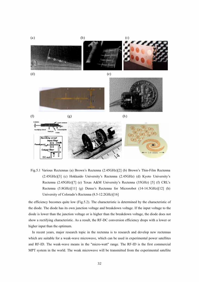
source. There are many researches of the rectenna elements (Fig.5.1). Famous research groups of the
rectenna are Texas A&M University in USA[5][9][14][18], NICT(National Institute of Information
and Communications Technology, past CRL) in Japan[8][10][11][17], and Kyoto University in
Japan[7][12][23]. The antenna of rectenna can be any type such as dipole[1]-[5], Yagi-Uda
antenna[6][7], microstrip antenna[8]-[12], monopole[13], loop antenna[14][15], coplanar patch[16],
spiral antenna[17], or even parabolic antenna[18]. The rectenna can also take any type of rectifying
circuit such as single shunt full-wave rectifier[4][9][10][11][13][14][16], full-wave bridge
rectifier[1][7][12][15], or other hybrid rectifiers[8]. The circuit, especially diode, mainly determines
the RF-DC conversion efficiency. Silicon Schottky barrier diodes were usually used for the previous
rectennas. New diode devices like SiC and GaN are expected to increase the efficiency. The
rectennas with FET[19] or HEMT[20] appear in recent years. The rectenna using the active devices
is not passive element.
The single shunt full-wave rectifier is always used for the rectenna. It consists of a diode inserted
to the circuit in parallel, a λ/4 distributed line, and a capacitor inserted in parallel. In an ideal
situation, 100% of the received microwave power should be converted into DC power[21]. Its
operation can be explained theoretically by the same way of a F-class microwave amplifier. The λ/4
distributed line and the capacitor allow only even harmonics to flow to the load. As a result, the
wave form on the λ/4 distributed line has a π cycle, which means the wave form is a full-wave
rectified sine form. The world record of the RF-DC conversion efficiency among developed
rectennas is approximately 90% at 4W input of 2.45 GHz microwave[1]. Other rectennas in the
world have approximately 70 – 90 % at 2.45GHz or 5.8GHz microwave input.
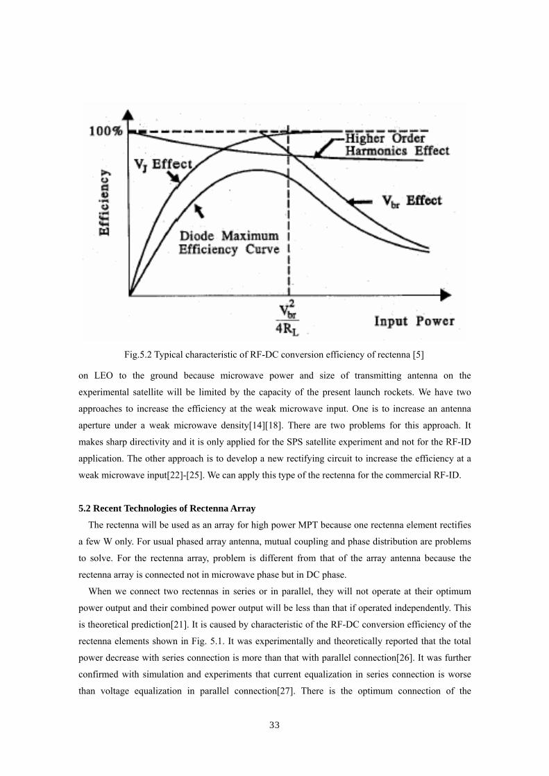
The RF-DC conversion efficiency of the rectenna with a diode depends on the microwave power
input intensity and the connected load. It has the optimum microwave power input intensity and the
optimum load to achieve maximum efficiency. When the power or load is not matched the optimum,
32
the efficiency becomes quite low (Fig.5.2). The characteristic is determined by the characteristic of
the diode. The diode has its own junction voltage and breakdown voltage. If the input voltage to the
diode is lower than the junction voltage or is higher than the breakdown voltage, the diode does not
show a rectifying characteristic. As a result, the RF-DC conversion efficiency drops with a lower or
higher input than the optimum.
In recent years, major research topic in the rectenna is to research and develop new rectennas
which are suitable for a weak-wave microwave, which can be used in experimental power satellites
and RF-ID. The weak-wave means in the "micro-watt" range. The RF-ID is the first commercial
MPT system in the world. The weak microwave will be transmitted from the experimental satellite
(a) (b) (c)
(d) (e)
(f) (g) (h)
Fig.5.1 Various Rectennas (a) Brown’s Rectenna (2.45GHz)[2] (b) Brown’s Thin-Film Rectenna
(2.45GHz)[3] (c) Hokkaido University’s Rectenna (2.45GHz) (d) Kyoto University’s
Rectenna (2.45GHz)[7] (e) Texas A&M University’s Rectenna (35GHz) [5] (f) CRL’s
Rectenna (5.8GHz)[11] (g) Denso’s Rectenna for Microrobot (14-14.5GHz)[12] (h)
University of Colorado’s Rectenna (8.5-12.2GHz)[16]
33
on LEO to the ground because microwave power and size of transmitting antenna on the
experimental satellite will be limited by the capacity of the present launch rockets. We have two
approaches to increase the efficiency at the weak microwave input. One is to increase an antenna
aperture under a weak microwave density[14][18]. There are two problems for this approach. It
makes sharp directivity and it is only applied for the SPS satellite experiment and not for the RF-ID
application. The other approach is to develop a new rectifying circuit to increase the efficiency at a
weak microwave input[22]-[25]. We can apply this type of the rectenna for the commercial RF-ID.
5.2 Recent Technologies of Rectenna Array
The rectenna will be used as an array for high power MPT because one rectenna element rectifies
a few W only. For usual phased array antenna, mutual coupling and phase distribution are problems
to solve. For the rectenna array, problem is different from that of the array antenna because the
rectenna array is connected not in microwave phase but in DC phase.
When we connect two rectennas in series or in parallel, they will not operate at their optimum
power output and their combined power output will be less than that if operated independently. This
is theoretical prediction[21]. It is caused by characteristic of the RF-DC conversion efficiency of the
rectenna elements shown in Fig. 5.1. It was experimentally and theoretically reported that the total
power decrease with series connection is more than that with parallel connection[26]. It was further
confirmed with simulation and experiments that current equalization in series connection is worse
than voltage equalization in parallel connection[27]. There is the optimum connection of the
Fig.5.2 Typical characteristic of RF-DC conversion efficiency of rectenna [5]
34
rectenna array.
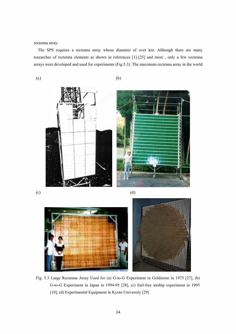
The SPS requires a rectenna array whose diameter of over km. Although there are many
researches of rectenna elements as shown in references [1]-[25] and more , only a few rectenna
arrays were developed and used for experiments (Fig.5.3). The maximum rectenna array in the world
(a) (b)
(c) (d)
Fig. 5.3 Large Rectenna Array Used for (a) G-to-G Experiment in Goldstone in 1975 [27], (b)
G-to-G Experiment in Japan in 1994-95 [28], (c) fuel-free airship experiment in 1995
[10], (d) Experimental Equipment in Kyoto University [29]
35
is that used for a ground to ground experiment in Goldstone by JPL, USA, in 1975[28] as shown in
the section of MPT history. The size was 3.4 m x 7.2 m = 24.5 m2. A rectenna array that had 2,304
elements and whose size was 3.54 m x 3.2 m was developed for a ground to ground experiment
conducted by Kyoto University, Kobe University, and Kansai Electric Corporation in 1994[26][29].
Kyoto University has several types of rectenna arrays at 2.45 GHz and 5.8 GHz[30]. These sizes are
approximately 1mφ. Another rectenna array with the size of 2.7 m x 3.4 m was developed for MPT
to fuel-free airship experiment with conducted by CRL (Communication Research Laboratory, NICT
in present) in Japan and Kobe University in 1995[10]. There is a large gap between these arrays of a
few meters in size and the SPS array of kilometers in diameter. Research of larger scale rectenna
arrays is required.
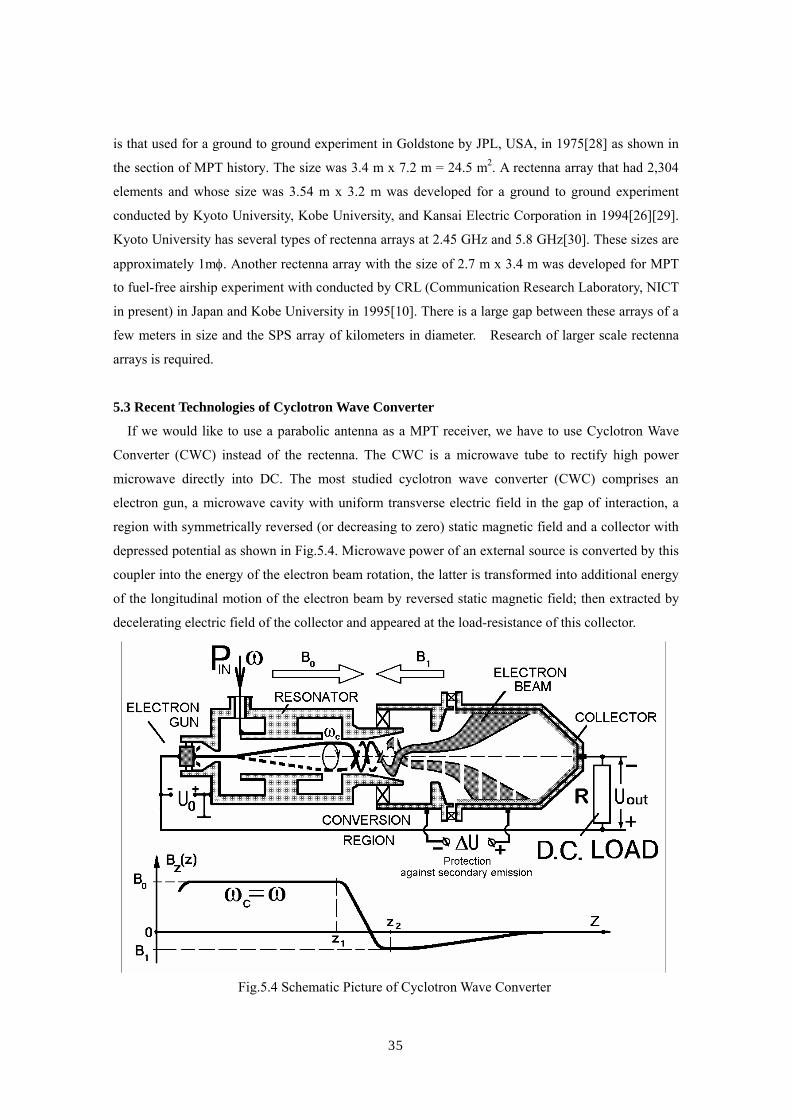
5.3 Recent Technologies of Cyclotron Wave Converter
If we would like to use a parabolic antenna as a MPT receiver, we have to use Cyclotron Wave
Converter (CWC) instead of the rectenna. The CWC is a microwave tube to rectify high power
microwave directly into DC. The most studied cyclotron wave converter (CWC) comprises an
electron gun, a microwave cavity with uniform transverse electric field in the gap of interaction, a
region with symmetrically reversed (or decreasing to zero) static magnetic field and a collector with
depressed potential as shown in Fig.5.4. Microwave power of an external source is converted by this
coupler into the energy of the electron beam rotation, the latter is transformed into additional energy
of the longitudinal motion of the electron beam by reversed static magnetic field; then extracted by
decelerating electric field of the collector and appeared at the load-resistance of this collector.
Fig.5.4 Schematic Picture of Cyclotron Wave Converter

36
The first CWC experiment was carried out by D. C. Watson, R. W. Grow, and C. C.
Jonson[31]-[33]. The first CWC could rectify only 1-1.5 W input with 56% efficiency. At Moscow
State University, a variant of the CWC was tested and its efficiency was 70-74% at 25-25W. The
TORIY Corporation and Moscow State University collaborate to create a several high power CWC
with the efficiency of 60-83% at 10-20 kW[34]-[36]. They demonstrated the CWC at the WPT’95
conference in Kobe, Japan. Vanke’s group continue to improve the CWC in present[37][38].
European group planed to apply the CWC for a ground-to-ground MPT experiment in Re-union
Island[39].
5.4 Rectenna Site Issue
It is widely assumed that a commercially feasible SPS will be on the order of GW. It delivers
significant electric power, and can contribute to any national power grid. The technology for
connection to the grid already exists, although the output of the SPS is a direct current. The output
of thermal or nuclear power plant is an AC, because they must first drive a kind of
turbine-generators.
The SPS will be steady state base power system without CO2 emission. Its output is predictable.
We have no problems economically and technologically with connecting the SPS to an existent
power grid. Moreover, a GW class power plant is similar to a nuclear power plant or large
hydropower plant. Most of the grid connection issues, therefore, are the same.
In Japan, some simulations concerning the connection with the rectennas and the existent power
grid are carried out[40]. When The SPS connect to existent power grid, it has possibility that
accidents can occur at either the SPS side or the grid side. The grid is designed to take up the slack if
the SPS dropouts without warning. In some cases the output of the rectenna may lapse. However, the
DC power converter may be able to handle these lapses in most cases -- within a certain specified
range of lapses. If the lapse or power failure is too large, then output may cease. If connected to a
large existent grid, then the grid should be able to take up the slack, somehow. If an accident occurs
on the grid side, there is potential for trouble for the rectenna (power source to the grid). The grid
Fig.5.5 CWCs Developed in Russia [37]
37
may be hit by electrical storms (thunder storms), but the power failure duration should be very short,
short enough for the SPS to manage with such hits to the grid. However, a major accident at another
power source (resulting output failure for hours or days), may be difficult for the SPS to cope with.
More careful studies are needed on this matter.
References
[1] Brown, W. C., “The History of the Development of the Rectenna”, Proc. Of SPS microwave
systems workshop at JSC-NASA, Jan. 15-18, 1980, pp.271-280
[2] Brown, W. C., “Optimization of the Efficiency and Other Properties of the Rectenna Element”,
MTT- S International Microwave Symposium Digest of Technical Papers, Vol. 76, No.1 1976,
pp.142- 144
[3] Brown., W. C., “A Microwaver Powered, Long Duration, High Altitude Platform”, MTT- S
International Microwave Symposium Digest, Vol.86, No.1, 1986, pp.507- 510
[4] Alden A. and T. Ohno, “Single Foreplane high Power Rectenna”, Electronics Letters, Vol. 21, No.
11, 1992, pp.1072-1073
[5] Yoo, T. and K. Chang, “Theoretical and Experimental Development of 10 and 35 GHz Rectenna”,
IEEE Trans. MTT, Vol. 40, No. 6, 1992, pp.1259-1266
[6] Gutmann, R. J. and R. B. Gworek, “Yagi-Uda Receiving Elements in Microwave Power
Transmission System Rectennas”, Journal of Microwave Power, Vol.14, No.4, 1979, pp.313-320
[7] Shinohara, N., S. Kunimi, T. Miura, H. Matsumoto, and T. Fujiwara, “Open Experiment of
Microwave Power Experiment with Automatically Target Chasing System (in Japanese)”, IEICE
Trans. B-II, Vol.J81-B-II, No. 6, 1998, pp.657-661
[8] Ito, T., Y. Fujino, and M. Fujita, “Fundamental Experiment of a Rectenna Array for Microwave
Power Reception”, IEICE Trans. Commun., Vol.E-76-B, No.12, 1993, pp.1508-1513
[9] McSpadden, J. O. and K. Chang, “A Dual Polarized Circular Patch Rectifying Antenna at 2.45
GHz for Microwave Power Conversion and Detection”, IEEE MTT-S Digest, 1994,
pp.1749-1752
[10] Fujino, Y., M. Fujita, N. Kaya, S. Kunimi, M. Ishii, N. Ogihata, N. Kusaka, and S. Ida, “A Dual
Polarization Microwave Power Transmission System for Microwave propelled Airship
Experiment”, Proc. of ISAP’96, Vol.2, 1996, pp.393-396
[11] Saka, T., Y. Fujino, M. Fujita, and N. Kaya, An Experiment of a C Band Rectenna”, Proc. Of
SPS’97, 1997, pp.251-253
[12] Shinohara, N. and H. Matsumoto, “Experimental Study of Large Rectenna Array for Microwave
Energy Trasnmission”, IEEE Trans. MTT, Vol. 46, No.3, 1998, pp.261-268
[13] Shibata, T., Y. Aoki, M. Otsuka, T. Idogaki, and T. Hattori, “Microwave Energy Transmission
System for Microrobot”, IEICE-Trans. Electr., Vol. 80-C, No.2, 1997, pp.303-308

38
[14] Strassner, B. and K. Chang, “5.8-GHz Circularly Polarized Rectifying Antenna for Wireless
Microwave Power Transmission”, IEEE Trans. MTT, Vol. 50, No.8, 2002, pp.1870-1876
[15] Leroy, P., G. Akoun, B. Essakhi, L. Santandrea, L. Pichon, and C. Guyot, “An e.cient global
analysis of a rectenna using the combination of a full-wave model and a rational approximation”,
Eur. Phys. J. Appl. Phys. No.29, 2005, pp.39-43
[16] Chin, C. H. K, Q. Xue, and C. H. Chan, “Design of a 5.8-GHz Rectenna Incorporating a New
Patch Antenna”, IEEE Antenna and Wireless Propagation Lett. , Vol. 4, 2005, pp.175-178
[17] Hagerty, J. A., N. D. Lopez, B. Popovic and Z. Popovic, “Broadband Rectenna Arrays for
Randomly Polarized Incident Waves”, Proc. of 30th European Microwave Conference, 2000,
EuMC_JHnlBP_00.pdf
[18] Fujino, Y. and K. Ogimura, “A Rectangular Parabola Rectenna with Elliptical Beam for SPS
Test Satellite Experiment (in Japanese)”, Proc. of the Institute of Electronics, Information and
Communication Engineers, SBC-1-10, 2004, pp.S29-S20
[19] Suh, Y. H., and K. Chang, “A Novel Low-Cost High-Conversion Efficiency Microwave Power
Detector Using GaAs FET”, Microwave and Optical Tech. Lett., Vol. 44, No. 1, 2005, pp.29-31
[20] Gómez, C., J. A. García, A. Mediavilla, and A. Tazón, “A High Efficiency Rectenna Element
using E-pHEMT Technology”, Proc. of 12th GAAS Symposium, 2004, pp.315-318
[21] Gutmann, R. J. and J. M. Rorrego, “Power Combining in an Array of Microwave Power
Rectifiers”, IEEE Trans. MTT, Vol.MTT-27, No.12, 1979, pp.958-968
[22] Zibitou, J., M. Latrach, and S. Toutain, “Monolithic and Hybrid Integrated ZB Converter
Design”, Proc. of 4th International Conference on Solar Power from Space (SPS’04), 2004,
pp.111-116
[23] Zibitou, J., M. Latrach, and S. Toutain, “Wide Band Power Rectenna with High Sensitivity
Detection”, Proc. of 4th International Conference on Solar Power from Space (SPS’04), 2004,
pp.251-255
[24] Shinohara, N., H. Matsumoto, A. Yamamoto, H. Okegawa, T. Mizuno, H. Uematsu, H. Ikematsu,
and I. Mikami, “Development of High Efficiency Rectenna at mW input (in Japanese)”, Tech.
Report of IEICE, SPS2004-08(2005-01), pp.15-20, 2005
[25] Tada, K., K. Fujimori, M. Sanagi, and S. Nogi, “Characteristics of Microwave Rectification
Circuit with Couple Line Structure (in Japanese), Tech. Report of IEICE, SPS2004-07(2005-01),
pp.11-14, 2005
[26] Shinohara, N. and H. Matsumoto,” Experimental Study of Large Rectenna Array for Microwave
Energy Transmission”, IEEE-MTT, Vol.46, No.3, 1998, pp.261-268
[27] Miura, T., N. Shinohara, and H. Matsumoto, “Experimental Study of Rectenna Connection for
Microwave Power Transmission”, Electronics and Communications in Japan, Part 2, Vol. 84,
No.2,2001, pp.27-36
39
[28] Dickinson, R. M., “Performance of a High-Power 2.388-GHz Receiving Array in Wireless
Power Transmission over 1.54 km”, 1976 MTT-S Int. Microwave Symp. Digest, 1976,
pp.139-141
[29] Shimokura, M., N. Kaya, N. Shinohara, and H, Matsumoito, “Point-to-point microwave power
transmission experiment (in Japanese)”, Trans. Institute of Electric Engineers Japan, vol.116-B,
no.6, 1996, pp.648-653
[30] Matsumoto, H., K. Hashimoto, N. Shinohara, and T. Mitani, “Experimental Equipments for
Microwave Power Transmission in Kyoto University”, Proc. of the 4th Int. Conf. on Solar Power
from Space - SPS ’04,, 2004, pp.131-138
[31] Watson, D. C., R. W. Grow, and C. C. Jonson, “A Rectifier with Tranverse Interaction”, in
Microwave Power Engineering, ed. Okress E. C., Vol.1, 1968, Academic Press, New York and
London, pp.408-419
[32] Watson, D. C., K. T. Tabbot, and C. C. Jonson, “A Cyclotron Wave Microwave Power
Converter”, Proc. IEEE, No.11, 1965, p.1965
[33] Watson, D. C., R. W. Grow, and C. C. Jonson, “A Cyclotron Wave Rectifier for S-band and
X-band”, J. Microwave Power, Vol.5, No.2, 1970, p.72
[34] Vanke, V. A., V. M. Lopukhin, V. K. Rosnovsky, V. L. Savvin, and K. I. Sigorin, “Ground-based
Receiving/Convertin System for Space Solar Power Systems”, Radiotechnique & Electronics,
Vol.27, No.5, 1982, p.1014
[35] Vanke, V. A. and V. L. Savvin, “Cyclotron Wave Converter for SPS Ebergy Transmission
System”, Proc. of SPS’91, 1991, pp.515-520
[36] Vanke, V. A., V. L. Savvin, I. A. Boudzinski, and S. V. Bykovski, “Development of Cyclotron
Wave Converter”, Proc. of WPT’95, 1995, p.3-3
[37] Vanke, V. A., H. Matsumoto, N. Shinohara, and A. Kita, “Cyclotron Wave Converter of
Microwave into DC”, IEICE Trans. Electron, Vol. E81-C, No.7, 1998, pp.1136-1142
[38] Vanke, V. A., H. Matsumoto, and N. Shinohara, “On a Possibility to Decrease Magnetic
Intensity in Microwave/DC Cyclotron Wave Converter”, IEICE Trans. Electron, Vol. E86-C,
No.7, 2003, pp.1390-1392
[39] Celeste, A., P. Jeanty, and G Pignolet, “Case study in Reunion island, Acta Astronautica”, vol.
54, 2004, pp. 253-258
[40] Research and Study of SSPS (Space Solar Power System) (in Japanese), JAXA,/MRI, Science
and Technology Agency, 2005

40
6. Efficiency
We classify the MPT efficiency roughly into three stages; DC-RF conversion efficiency which
includes losses caused by beam forming, beam collection efficiency which means ratio of all
radiated power to collected power on a receiving antenna, and RF-DC conversion efficiency.
6.1 RF-DC Conversion Efficiency
The RF-DC conversion efficiency of the rectenna or the CWC is over 80 % of experimental
results as shown in Fig.6.1. Decline of the efficiency is caused by array connection loss, change of
optimum operation point of the rectenna array caused by change of connected load, trouble of the
rectenna, and any losses on the systems, for example, DC/AC conversion, cables, etc. However, it is
easier to keep high efficiency than that on the other two stages.
6.2 Beam Collection Efficiency
The beam collection efficiency depends on the transmitter and receiver aperture areas, the
wavelength, and the separation distance between the two antennas as shown in the section 1. For
example, it was calculated approximately 89% in the SPS reference system with the parameters as
follows; the transmitter aperture is 1 kmφ, the rectenna aperture is 10x13 km, the wavelength is
12.24 cm (2.45GHz), and the distance between the SPS and the rectenna 36,000 km[3]. They assume
10dB Gaussian power taper on the transmitting antenna. The beam pattern on the ground is shown in
Fig.6.2.
Decline of the efficiency is caused by phase/frequency/amplitude error on a phased array.
Phase/frequency/amplitude error on a phased array causes difference of beam direction and rise of
sidelobes. If we have enough large number of elements, the difference of the beam direction is
negligible. The rise of the sidelobe decreases antenna gain and beam collection efficiency.
If antenna planes separate each other structurally, grating lobes, whose power level is the same as
main beam, may occur and power can not be concentrated to the rectenna array. This problem occurs
in module-type phased array. The idea of random array has risen in order to suppress the grating
(a) Efficiency of 2.45GHz Rectenna[1] (b) Efficiency of 5.8GHz Rectenna[2]
Fig. 6.1 Efficiency of Rectenna Element

41
lobes. However, a sidelobe level increases, beam
collection efficiency decreases and have to
search for special techniques. Power in grating
lobes diffuses not to a main lobe but to sidelobes.
Therefore, we have to fundamentally suppress
the grating lobes for a MPT system.
6.3 DC-RF Conversion Efficiency
If we do not have to steer a microwave beam
electrically in a MPT, we can use a microwave
transmitter with high DC-RF conversion
efficiency over 70-80 % like microwave tubes.
However, if we need to steer a microwave beam
electrically without any grating lobes, we have
to use phase shifters with high loss. Especially in
the SPS system, the optimum and economical
size of the transmitting phased array and
microwave power are calculated as around a few
km and over a few GW, respectively. It means
that microwave power from one antenna element is much smaller than that from one microwave tube
or high power (over a several tens watts) semiconductor amplifier. It also means that phase shifter
have to be installed after the microwave generation/amplification (Fig.6.3) if microwave beam will
be steered to directions of larger than 5 degrees without grating lobes. In that case, development of
Fig.6.2 Beam Pattern on the Ground[1]
High Power
Oscillator
Multiple
Power
Divider
Phase-shifter? (Isolator)
Antenna
Antenna
Antenna
(Isolator)
(Isolator)
Phase-shifter?
Phase-shifter?
Fig. 6.3 Implementation of microwave transmission with a high power microwave oscillator and
phase-shifters for high precision control of microwave beam direction to large angles
without grating lobes
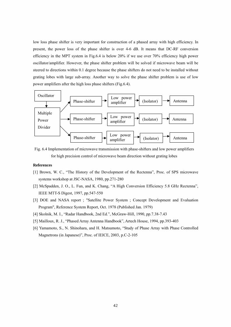
42
low loss phase shifter is very important for construction of a phased array with high efficiency. In
present, the power loss of the phase shifter is over 4-6 dB. It means that DC-RF conversion
efficiency in the MPT system in Fig.6.4 is below 20% if we use over 70% efficiency high power
oscillator/amplifier. However, the phase shifter problem will be solved if microwave beam will be
steered to directions within 0.1 degree because the phase shifters do not need to be installed without
grating lobes with large sub-array. Another way to solve the phase shifter problem is use of low
power amplifiers after the high loss phase shifters (Fig.6.4).
References
[1] Brown, W. C., “The History of the Development of the Rectenna”, Proc. of SPS microwave
systems workshop at JSC-NASA, 1980, pp.271-280
[2] McSpadden, J. O., L. Fun, and K. Chang, “A High Conversion Efficiency 5.8 GHz Rectenna”,
IEEE MTT-S Digest, 1997, pp.547-550
[3] DOE and NASA report ; "Satellite Power System ; Concept Development and Evaluation
Program", Reference System Report, Oct. 1978 (Published Jan. 1979)
[4] Skolnik, M. I., “Radar Handbook, 2nd Ed.”, McGraw-Hill, 1990, pp.7.38-7.43
[5] Mailloux, R. J., “Phased Array Antenna Handbook”, Artech House, 1994, pp.393-403
[6] Yamamoto, S., N. Shinohara, and H. Matsumoto, “Study of Phase Array with Phase Controlled
Magnetrons (in Japanese)”, Proc. of IEICE, 2003, p.C-2-105
Oscillator
Multiple
Power
Divider
Phase-shifter Low power amplifier (Isolator)
Antenna
Antenna
Antenna
(Isolator)
(Isolator)
Low power amplifier
Low power amplifier
Phase-shifter
Phase-shifter
Fig. 6.4 Implementation of microwave transmission with phase-shifters and low power amplifiers
for high precision control of microwave beam direction without grating lobes

43
7. Summary
The MPT is very old concept with newest technologies. We can advance energy systems from
RF-ID to the SPS. The SPS is the largest and most suitable MPT application. To realize the
commercial SPS, there are some research subjects to solve in order to decrease its cost. We have
already achieved a point-to-point MPT in 1970’s (Fig.6.1). We have also achieved a phased array
technologies with low efficiency. The problem in order to realize the SPS is high efficient phased
array for the MPT. The higher efficiency can suppress a cost of the SPS. There are some methods to
increase the efficiency of the MPT. One is a superconducting to reduce a loss in resistance. The other
is an achievement of higher accurate beam control to reduce a loss in beam focusing. New
semi-conductor device is expected for increasing the DC-RF and RF-DC conversion efficiency. The
SPS is future system. Based on the MPT application on the ground, we have to advance the MPT
technologies.
Fig.6.1 History and Future of the MPT
End of 19th Century –Begining of 20th Century - Theoretical Possibility -
Completion of WPT on ground
After World War II- Demonstration -
Glaser
Brown
Wireless Power Transmission via Microwave
After World War II- Demonstration -
Glaser
Brown
Wireless Power Transmission via Microwave
Maxwell
Hertz
Tesla
Space UseHighly EfficientPhased Array
Thermal and Structural Design
End of 20th Century – 21st Century- Advance for SSPS -


![Design and Analysis of Efficient Pulse-driven Magnetically ......good application prospect in wireless charging [16-17], Solar Power Satellite (SPS), Space Solar Power (SSP) [18-20],](https://img.pdfslide.us/doc/110x75/5ff53de8c37f776b562fbdf6/design-and-analysis-of-efficient-pulse-driven-magnetically-good-application.jpg)