Embed Size (px)
Citation preview
.
NASA Contractor Report 3317
Satellite Concept
Volume I
Power Systems (SPS) Definition Study
- Executive Summary
G. M. Hanley
CONTRACT NAS8-32475 SEPTEMBER 1980
NASA CR 3317- ! v,l c.1 I
https://ntrs.nasa.gov/search.jsp?R=19800022396 2018-05-10T23:33:18+00:00Z
TECH LIBRARY KAFB, NM
NASA Contractor Report 3317
Satellite Power Systems (SPS) Concept Definition Study
Volume I - Executive Summary
G. M. Hanley Rockwell Intervzatiovlal Downey, California
Prepared for Marshall Space Flight Center under Contract NAB-32475
National Aeronautics and Space Administration
Scientific and Technical Information Branch
1980

FOREWORD
Volume I, Executive Summary, of the SPS Concept Definition Study final report is submitted by Rockwell International through the Satellite Systems Division. All work was completed in response to NASA/MSFC Contract NAS8-32475, Exhibit C, dated March 28, 1978.
The SPS final report will provide the NASA with additional information on the selection of a viable SPS concept, and will furnish a basis for sub- sequent technology advancement and verification activities. Other volumes of the final report are listed below.
Volume Title
II System Engineering
III Experimentation/Verification Element Definition
IV Transportation Analyses
V Special-Emphasis Studies
VI
VII
In-Depth Element Investigation
Systems/Subsystems Requirements Data Book
The SPS Program Manager, G. M. Hanley, may be contacted on any of the technical or management aspects of this report. He can be reached at 213/594-3911, Seal Beach, California.
iii

c -
CONTENTS
Page
INTRODUCTION ............ 1 STUDY OBJECTIVES ........... 2 RELATIONSHIP TO OTHER NASA EFFORT ....... 2 METHOD OF APPROACH AND PRINCIPAL ASSUMPTIONS . , . . 3 BASIC DATA GENERATED AND SIGNIFICANT RESULTS .... 5
SYSTEM DEFINITION .......... 5 Reference System ......... 6 Major Alternative Study Results ..... 8 Solid State Microwave Transmission Concepts . . 14 Laser Transmission Environmental Analysis . . 16
SPECIAL EMPHASIS STUDIES ........ 17 Satellite Construction ........ 17 Satellite Construction Base Construction ... 26 Rectenna Construction ....... 32 Space Logistics ......... 37
TRANSPORTATION SYSTEM STUDIES ....... 38 Heavy Lift Launch Vehicle ...... 40 Electric Orbit Transfer Vehicle ..... 40 Personnel Orbit Transfer Vehicle ..... 42
PROGRAM DEFINITION ......... 42 STUDY LIMITATIONS ........... 47 IMPLICATIONS FOR RESEARCH ......... 47
MICROWAVE GROUND-BASED EXPLORATORY RESEARCH PROGRAM . 47 KEY TECHNOLOGY PROGRAM ........ 51 SPS ORBITAL TEST PLATFORM DEMONSTRATION PROGRAM . . 52 PILOT PLANT DEMONSTRATION PHASE ...... 54
SUGGESTED ADDITIONAL EFFORT ........ 57 SYSTEM STUDIES .......... 57 TECHNOLOGY DEVELOPMENT ........ 57
REFERENCES. ............ 5g

ILLUSTRATIONS
Figure
1 2 3 4 5 6 7 8 9
10 11 12 13 14 15 16 17 18 19 20 21 22 23 24 25 26 27 28 29 30 31 32 33 34 35 36 37 38 39 40 41 42 43 44
Satellite Power System Concept . , . . Study Flow . . . . . . . . . Rockwell Satellite Point Design . . . SPS Reference System Satellites . . . Alternative Antenna Structural Concepts . Alternative Rectenna Concepts . . . . Recommended Satellite Concept . . . . EOL Efficiency Chain for Recommended Concept Dual Microwave Antenna Concept . . . . Sandwich Panel Solid State Concept . . . Satellite Construction Approaches . . . Serpentine Satellite Construction Base (SCB) Overall Structure Concept . . . Single-Pass Satellite Construction Base'(&) Construction Timeline . . . . . . Sequence of Construction Events . . . Antenna Supporting Structure Fabrication . Antenna Primary Structure Fabrication . . Typical Solar Array Bay Construction . . Reflector Packaging and Installation . . Solar Array Installation Concept . . .
.
.
.
.
.
.
.
.
.
.
.
.
.
.
.
.
.
.
.
.
.
.
.
.
.
.
.
.
.
.
.
.
.
.
.
.
.
.
.
Manned Operations at Solar Array Installation Stations Overall Satellite Construction Scenario . . . Triangular Element Fabrication Facility . . . Mobile 79m Girder Fabrication Facility . . . . SCB Primary Structure . . . . . . . . SCB Secondary Structure . . . . . . . Parallel Fabrication of EOTV's . . . . . . SCB Orbit Transfer Configuration . . . . . Operational Ground Receiving Facility (Rectenna) . Panel Installation . . . . . . . . . Typical Rectenna Module . . . . . . . Panel Loading Sequence . . . . . . . . Rectenna Construction Sequence . . . . . . Electrical Installation and Hookup . . . . . Rectenna Site Construction Schedule . . . . Mass Carried to LEO in HLLV . . . . . . SPS Space Transportation Scenario . . . . . Two-Stage, Parallel Burn HLLV Concept . . . . Single-Stage to Orbit HLLV Concept (Star-Raker) . EOTV Configuration . . . . . . . . . SPS Summary Program Phases and Milestones . . . SPS Cost Breakdown . . . SPS Evolutionary Development Plan Elements . . .
.
.
.
.
.
.
.
.
.
.
.
.
.
.
.
.
.
.
.
.
.
.
.
.
.
.
.
.
.
.
.
.
.
.
.
.
.
.
.
.
.
.
.
. 1
. 3
. 5
. 7
. 11
. 12
. 13
. 13
. 15
. 16
. 18
. 19
. 20
. 20
. 22
. 22
. 23
. 24
. 25
. 25
. 27
. 28
. 28
. 29
. 29
. 30
. 31
. 31
. 32
. 33
. 33
. 34
. 34
. 35
. 37
. 37
. 38
. 39
. 41
. 41
. 42
. 44
. 45
. 48
Page
Vii
Figure Page
Major Elements of Ground Based Exploratory Research (GBER) Program. . . . . . . . . . . . . 49
GBER Program Flow Diagram Technical Approach . . . . 49 GBER Program Cost Estimates . . . . . . . . 50 Key Technology Program Summary . . . . . . . . 52 SPS GE0 Multi-Test Platform and Inverted Test Range . . 53 SPS GE0 Multi-Test System . . . . . . . . . 53 SPS Pilot Plant in Final Phases of Construction . . . 55
45
46 47 48 49 50 51
viii
Table
TABLES
Page
Rockwell Point Design Description . . . ; . . . 6 SPS Reference Sys tern Description . . . . . . . 7 Effect of Antenna Location and Number of Troughs on
Satellite Mass (Million kg). . . . . . . . . 9 Recommended Satellite Concept . . . . . . . . 13 Recommended Satellite Concept Mass Properties . . . . 14 Constructability Comparison . . . . . . . . 21 Construction Summary . . . . . . . . . . 37 Yearly Space Transportation Rates . . . . . . . 39 HLLV Ground Rules and Assumptions . . . . . . . 40 SPS Program Plans . . . . . . . . . . 45
1 2 3
4 5 6 7 8 9
10
ix
INTRODUCTION
The Department of Energy (DOE) is currently conducting an evaluation of approaches to provide energy that will meet demands in the post-2000 time period. The Satellite Power System (SPS) is a candidate for producing sig- nificant quantities of base-load power using solar energy as the source.
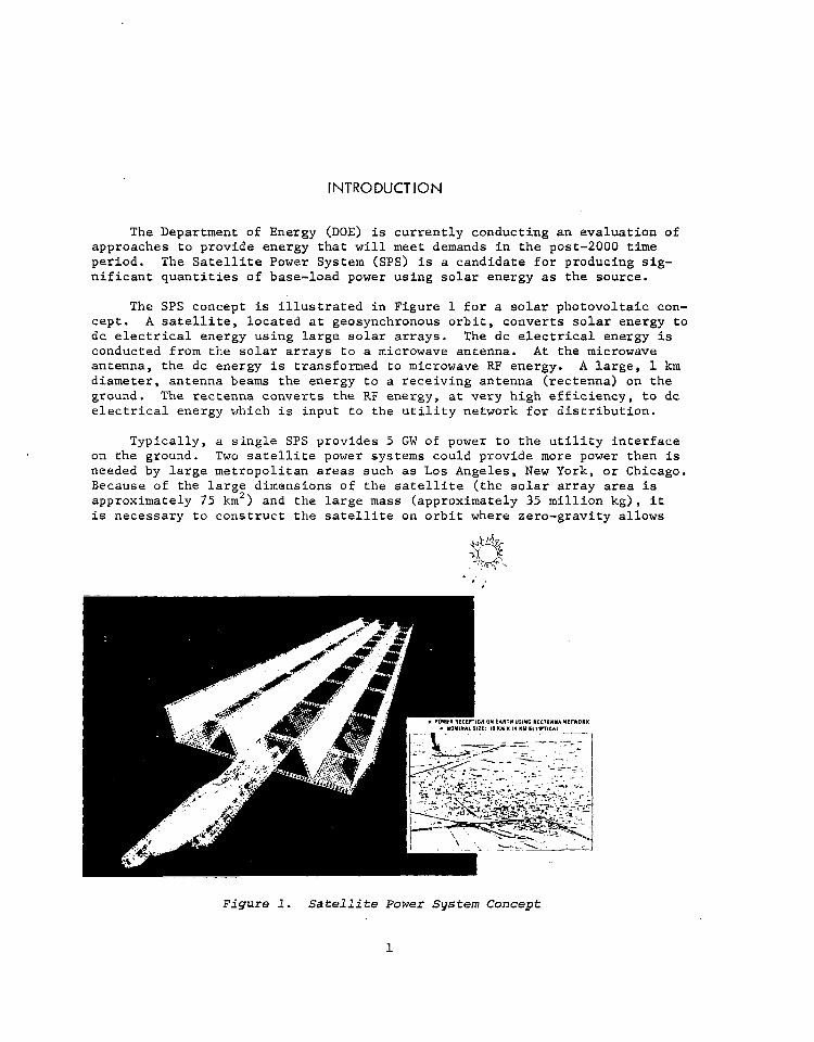
The SPS concept is illustrated in Figure 1 for a solar photovoltaic con- cept. A satellite, located at geosynchronous orbit, converts solar energy to dc electrical energy using large solar arrays. The dc electrical energy is conducted from the solar arrays to a microwave antenna. At the microwave antenna, the dc energy is transformed to microwave RF energy. A large, 1 km diameter, antenna beams the energy to a receiving antenna (rectenna) on the ground. The rectenna converts the RF energy, at very high efficiency, to dc electrical energy which is input to the utility network for distribution.
Typically, a single SPS provides 5 GW of power to the utility interface on the ground. Two satellite power systems could provide more power then is needed by large metropolitan areas such as Los Angeles, New York, or Chicago. Because of the large dimensions of the satellite (the solar array area is approximately 75 km') and the large mass (approximately 35 million kg), it is necessary to construct the satellite on orbit where zero-gravity allows
Figure 1. Satellite Power System Concept
1
very low structural mass. The ground-located rectenna is nominally an ellip- tical array 10 km by 13 km. At the earth's surface, the microwave beam has a maximum intensity in the center of 23 mW/cm2 (less than l/4 the solar constant) and an intensity of less than 1 mW/cm2 outside of'the rectenna fenceline (10 mW/cm2 is the current United States microwave exposure standard).
This study is a continuing effort to provide system definition data to aid in the evaluation of the SPS concept by DOE. The total DOE program includ- es system definition (of which this study is a part); socioeconomic studies; environmental, health, and safety studies; and a comparative assessment of SPS with other candidate energy concepts. This is the second year of contract effort which is being conducted for NASA Marshall Space Flight Center. The first year's effort, completed in April 1978, is reported in Reference 1. One of the major results of the first year of effort was data used by NASA to de- fine two reference concepts which are being used by DOE for their evaluation. This year's effort concentrated, on a more detailed definition of the reference concept, trades relative to the reference concept, conceptual approaches to a solid-state microwave transmission alternative to the reference concept, and further definition of the program. This volume summarizes that effort.
STUDY OBJECTIVES
The objective of this effort is to provide system definition data to NASA/MSFC to support DOE evaluation of SPS. Two major NASA milestones were supported: Reference Concept Definition (Reference 2) and Program Plan Recommendations.
RELATIONSHIP TO OTHER NASA EFFORT
This study supports the in-house SPS system definition effort being conducted by NASAfMSFC. NASA/JSC also is conducting a parallel system definition effort and is being supported under contract by the Boeing Company. Together, these studies form the basis for the NASA Office of Energy Programs inputs to the Department of Energy. This study also will provide requirements for technology development in the large structure, solar array, power distribu- tion, microwave transmission, space operations, and space transportation systems areas.
METHOD OF APPROACH AND PRINCIPAL ASSUMPTIONS
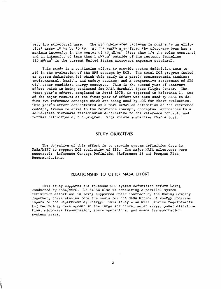
A time-related study flow diagram that summarizes the study approach is shown in Figure 2. The major data base was documentation from the previous Rockwell SPS Concept Definition Study (Exhibits A and B). Additional data included dbcumentation of the Boeing Company SPS Concept Definition Study and results of NASA (MSFC and JSC) in-house SPS studies.
REFERENCE SYSTEM
AIPN NA” JUNE JULY AUG SEPT OCT “0” DEC J&N FEB NAN
1978 1979
Figure 2. Study Flow
During the first 3 months of the study, major emphasis was placed on an update of the point design defined in Contract Exhibits A and B. The update resulted from additional trade studies conducted during the first 3 months. The updated point design and similar data from the Boeing Company studies and NASA in-house studies resulted in a preliminary description by NASA and DOE of a reference system. The purpose of the reference system is to provide a specific single data base for the SPS concept evaluation being conducted by DOE. The reference system was then defined and a report was issued by NASA/ DOE that describes this system and contains key trade studies leading to definition of this system. This system description formed the basis for a series of studies (construction, transportation, experiment/verification program, and cost) that further defined the concept and program. In addition, a series of trade studies at the total system level and at the subsystem level were conducted to identify modifications to the currently-defined reference system and to define alternative system concepts which have the potential for significant improvements.
3
The major outputs of the study are shown in Figure 2. The constructabil- ity studies resulted in the definition of the concepts for satellite, rectenna, and satellite construction base construction. Transportation analyses resulted in definition of heavy-lift launch vehicle (HLLV), electric orbit transfer vehicle (EOTV), personnel orbit transfer vehicle (POTV), and intra-orbit trans- fer vehicle (IOTV) as well as overall operations related to transportation systems. The experiment/verification program definition resulted in the defi- nition of elements for the Ground-Based Experimental Research (GBER) and Key Technology plans. These studies also resulted in conceptual approaches for early space technology verification. The cost analysis defined the overall program and cost data for all program elements and phases.
This data will form the basis for further program definition and is the basis for recommended future effort.
BASIC DATA GENERATED AND SIGNIFICANT RESULTS
This section summarizes the significant study results. First, an over- view of the system definition effort is presented. This is followed by a description of the special emphasis studies, which concentrated on system construction; a summary of the space transportation system; and a total program and program cost summary.
SYSTEM DEFINITION
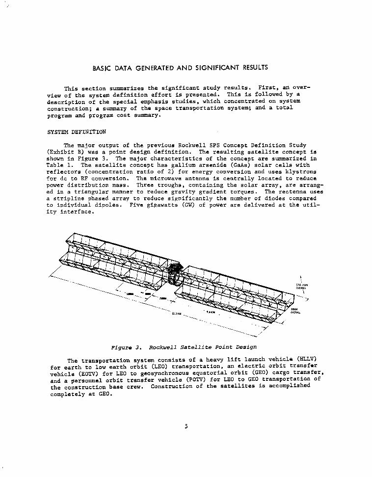
The major output of the previous Rockwell SPS Concept Definition Study (Exhibit B) was a point design definition. The resulting satellite concept is shown in Figure 3. The major characteristics of the concept are summarized in Table 1. The satellite concept has gallium arsenide (GaAs) solar cells with reflectors (concentration ratio of 2) for energy conversion and uses klystrons for dc to RF conversion. The microwave antenna is centrally located to reduce power distribution mass. Three troughs, containing the solar array, are arrang- ed in a triangular manner to reduce gravity gradient torques. The rectenna uses a stripline phased array to reduce significantly the number of diodes compared to individual dipoles. Five gigawatts (GW) of power are delivered at the util- ity interface.
Figure 3. Rockwell Satellite Point Design
The transportation system consists of a heavy lift launch vehicle (HLLV) for earth to low earth orbit (LEO) transportation, an electric orbit transfer vehicle (EOTV) for LEO to geosynchronous equatorial orbit (GEO) cargo transfer, and a personnel orbit transfer vehicle (POTV) for LEO to GE0 transportation of the construction base crew. Construction of the satellites is accomplished completely at GEO.
5
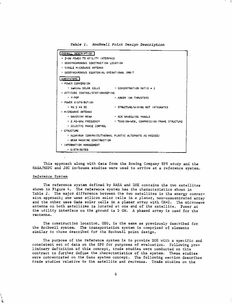
Table 1. Rockwell Point Design Description
1 OVERALL DESCRIPTIOtl
l 5-GW POWER TO UTILITY INTERFACE
- GEOSYNCHRONOUS CONSTRUCTION LOCATION
* SINGLE Ml CROWAVE ANTENNA
* GEOSYNCHRONOUS EQUATORIAL OPERATIONAL ORBIT
* POWER CONVERSION
* GaAlAs SOLAR CELLS * CONCENTRATION RATIO = 2
* ATTITUDE CONTROL/STATIONKEEPING
* Y-POP * ARGON ION THRUSTERS
* POWER OlSTRlBUTlON
. 45.5 KV DC - STRUCTURE/WIRING NOT INTEGRATED
. fllCROWAVE ANTENNA
* GAUSSIAN BE&l . RCR WAVEGUIDE PANELS
. 2.‘15-GHz FREQUENCY * TENSION-WEB, COMPRESSION FRAME STRUCTURE
* ECLECTIC PHASE CONTROL
’ STRUCTURE
* ALUtllNUM (GRAPHITE/THERMAL PLASTIC ALTERNATE AS NEEDED)
. BEAM MACHINE CONSTRUCTION
* I NFDRHAT I DN MANAGEMENT
. DISTRIBUTED
This approach along with data from the Boeing Company SPS study and the NASA/MSFC and JSC in-house studies were used to arrive at a reference system.
Reference System
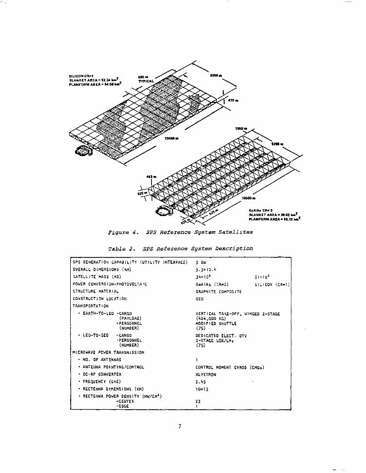
The reference system defined by NASA and DOE contains the two satellites shown in Figure 4. The reference system has the characteristics shown in Table 2. The major difference between the two satellites is the energy conver- sion approach; one uses silicon solar cells in a planar, non-concentrated array and the other uses GaAs solar cells in a planar array with CR=2. The microwave antenna on both satellites is located at one end of the satellite. Power at the utility interface on the ground is 5 GW. A phased array is used for the rectenna.
The construction location, GEO, is the same as previously described for the Rockwell system. The transportation system is comprised of elements similar to those described for the Rockwell point design,
The purpose of the reference system is to provide DOE with a specific and consistent set of data on the SPS for purposes of evaluation. Following pre- liminary definition of this concept, trade studies were conducted on this contract to further define the characteristics of the system. These studies were concentrated on the GaAs system concept. The following section describes trade studies relative to the satellite and rectenna. Trade studies on the
6
SILICDN CR-1 BLANKET AREA- S2.Y rln’ PLANFORM AREA - 84.08 d
BLANKET AREA - Z..SZ Ln’
PUNFORM AREA - Ml3 ld
Figure 4. SPS Reference System Satellites
Table 2. SPS Reference System Description
SPS GENERATIDH CAPABILITY (UTILITY INTERFACE) 5 GW OVERALL DIMENSIONS (KM) 5.3x10.4
SATELLITE NASS (KG) 34x106 51x106
POWER CONVERSION-PHOTDVOLTAIC GaAlAs (CR-21 SILICON (CR-I
STRUCTURE HATERI AL GRAPHITE COHPOSITE
CONSTRUCT I ON LOCAT ION GE0
TRANSPORTAT I ON
* EARTH-TO-LED -CARGO (PAYLOAD)
VERTICAL TAKE-OFF, WINGED 2-STAGE (424,000 KG)
-PERSONNEL t4OOIFIED SHUTTLE (NUtiBER) (75)
* LEO-TO-GED -CARGO DEDICATED ELECT. OTV -PERSONNEL 2-STAGE LOX/LHz
(NUMBER) (75) ‘IICROWAVE PCWER TRANSHISSION
* NO. OF ANTENNAS I
* ANTENNA POI NT I NC/CONTROL CONTROL MOMENT GYROS (CHGs)
* DC-RF CONVERTER KLYSTRON
* FREQUENCY (GHZ) 2.45
- RECTENNA DIHENSIONS (KM) 10x13
- REtTEtiNA POWER DENSITY (H~/CH~) -CENTER 23 -EDGE 1
7
transportation system are described in the Transportation Analysis section and trade studies related to construction are contained in the Special Emphasis Studies section. Two areas where major departures from the reference system were studied are laser energy transmission environmental impacts and solid- state microwave transmission. These results are contained in two separate sections following the next section.
Major Alternative Study Results
Major alternatives to the reference system that were studied following its preliminary definition include the following:
The results of these studies are described below.
Coplanar versus triangular solar array trough arrangement
Number of solar array troughs
Central versus end-mounted antenna
Aluminum versus composite structure
Antenna structural concept
Alternative rectenna phased arrays
Coplanar Versus Triangular Solar Array Trough Arrangement. The main pur- pose of the triangular trough arrangement in the Rockwell point design was to reduce the attitude control requirements due to gravity gradient torques. Continued studies of the attitude control requirements and integration of these requirements with stationkeeping requirements revealed that stationkeep- ing for solar pressure perturbations was the dominant requirement. It also was determined that the attitude control requirements could be met even for a coplanar trough with no further propellant impact than that required for solar pressure stationkeeping. Therefore, the coplanar trough arrangement of the baseline concept,is the recommended concept.
Number of Solar Array Troughs. Trade studies related to the number of troughs considered the impact on the construction facility and on the SPS system weight and cost. Location of the microwave antenna (central versus end-mounted) also is a consideration in this trade study. The impact of number of troughs and antenna location on mass are shown in Table 3 for G&s, CR-2 concepts. For the centrally-located antenna, the mass is slightly less for a 3 trough concept when compared to 4 trough concept. The 3 trough con- cept has a slightly greater mass than the 4 trough concept for an end-mounted antenna.
The smaller number of troughs is desired from the construction base point of view regardless of the method of construction. (Two methods of construction, single-pass and serpentine, were considered and will be described later in this Summary Report.) In the serpentine construction approach, one trough is com- pleted before the next is started. The greater the number of troughs, the greater the complexity because of the complexity of operations for transfer of the facility to initiate construction of another trough. In the single pass
8
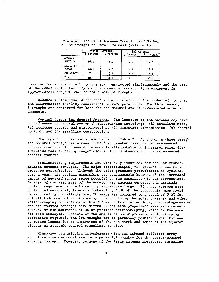
Table 3. Effect of Antenna Location and Number of Troughs on Satellite Mass (Million kg)
CENTRAL ANTENNA END ANTENNA 3 TROUGHS 4 TROUGHS 3 TROUGHS 4 TROUGHS
ANTENNA SECT ION 16.3 16.3 16.3 16.3
COLLECTOR ARRAY 12.3 12.5 14.0 13.7
25% GROWTH 7.1 7.2 7.6 7.5 TOTAL 35.7 36.0 37.9 37.5
construction approach, all troughs are constructed simultaneously and the size of the construction facility and the amount of construction equipment is approximately proportional to the number of troughs.
Because of the small difference in mass related to the number of troughs, the construction facility considerations were paramount. For this reason, 3 troughs are preferred for both the end-mounted and center-mounted antenna concepts.
Central Versus End-Mounted Antenna. The location of the antenna may have an influence on several system characteristics including: (1) satellite mass, (2) attitude control and stationkeeping, (3) microwave transmission, (4) thermal control, and (5) satellite construction.
The impact on mass was already shown in Table 2. end-mounted concept has a mass 2.2~10~
As shown, a three trough kg greater than the center-mounted
antenna concept. The mass difference is attributable to increased power dis- tribution mass caused by longer distribution distances for the end-mounted antenna concept.
Stationkeeping requirements are virtually identical for end- or center- mounted antenna concepts. The major stationkeeping requirement is due to solar pressure perturbation. Although the solar pressure perturbation is cyclical over a year, the orbital excursions are unacceptable because of the increased amount of geosynchronous space occupied by the satellite without corrections. Because of the assymetry of the end-mounted antenna concept, the attitude control requirements due to solar pressure are large. If these torques were controlled separately from stationkeeping, 4.0% of the spacecraft mass would be required in propellants over 30 years (as compared to a total of 5.6% for all attitude control requirements). By combining the solar pressure and other stationkeeping corrections with attitude control corrections, the center-mounted and end-mounted concepts have virtually the same propellant mass requirements because of the dominance of solar pressure stationkeeping, which is the same for both concepts. Because of the amount of solar pressure stationkeeping correction required, the SPS troughs can be partially pointed toward the sun to reduce losses due to excursions of the sun north and south of the equator without an attitude control propellant penalty.
Microwave transmission interference with the inboard collector array structure also was considered as a potential penalty for the center-mounted antenna concept. However, because of the large antenna aperature, spreading
9
of the beam and side lobe formation is negligible in the neighborhood of the satellite. As long as no structure is located such that a normal from the antenna intersects it, no interference should occur. The center-mounted con- cept is designed to satisfy this constraint.
Because carry-through and rotary joint structure is located directly be- hind the microwave antenna where waste heat from the klystrons is being reject- ed, there is some concern of the thermal impacts. Thermal control can be achieved to an acceptable level for either aluminum or graphite composites by surface coating or surface covering at a negligible weight penalty.
Satellite construction studies indicate some additional construction com- plexity due to the center located antenna. At this time, the complexity is difficult to trade off against the additional mass required for the end-mounted concept.
As a result of these trade studies, it was concluded that either antenna location results in a feasible concept. The only significant penalty identi- fied was the mass increase for the end-mounted antenna of 2-.2X106 kg. For this reason, the center-mounted concept is preferred, but either satellite concept is acceptable.
Aluminum Versus Composite Structure. The triangular trough arrangement concept (Rockwell point design) previously shown in Figure 3 was used to con- duct a detailed structural analysis using the NASTRAN computer model. It was assumed that construction occurred at a uniform temperature of O'C, that cal- culated equilibrium temperatures occurred during normal operation in the sun, and that a minimum temperature of -150°C occurs during an eclipse of the sun by the earth. Results of this analysis showed maximum structural deflections at the solar array tips of 100 m for aluminum structure and 1.1 m for compos- ite structure. Detailed analysis of tribeam loading revealed that local load- ing for aluminum structure caused by deflections exceeded crippling allowables of the elemental caps for a 10 mil thickness aluminum structure. For some regions, material thicknesses up to 30 mils would be required. If all members were constrained to a 30 mil aluminum material thickness, a structural weight of up to lOxlO6 kg would result for aluminum structure compared to 1.2x10⁶ kg for composite structure. This maximum value for aluminum could be reduced by about one-half by selectively using 30 ml1 structure only in the lateral structure where crippling allowables are exceeded and 10 mil structure in the longitudinal structure.
The major problem with the composite structure is the current lack of knowledge on lifetime in orbit. The 30-year SPS requirement is much more severe than for other spacecraft.
As a result of these trade studies, it was concluded that either aluminum or composite structure can be used for SPS. Because of the lower deflections, induced stresses, and lower weight of composite structure, it is recommended for the satellite structure. Research is required to assure either that current composite structure applicable to SPS will survive the space environ- ment for 30 years or that composite structure materials can be formulated that will survive the space environment for 30 years. Aluminum structure can be carried as a viable alternative.
10
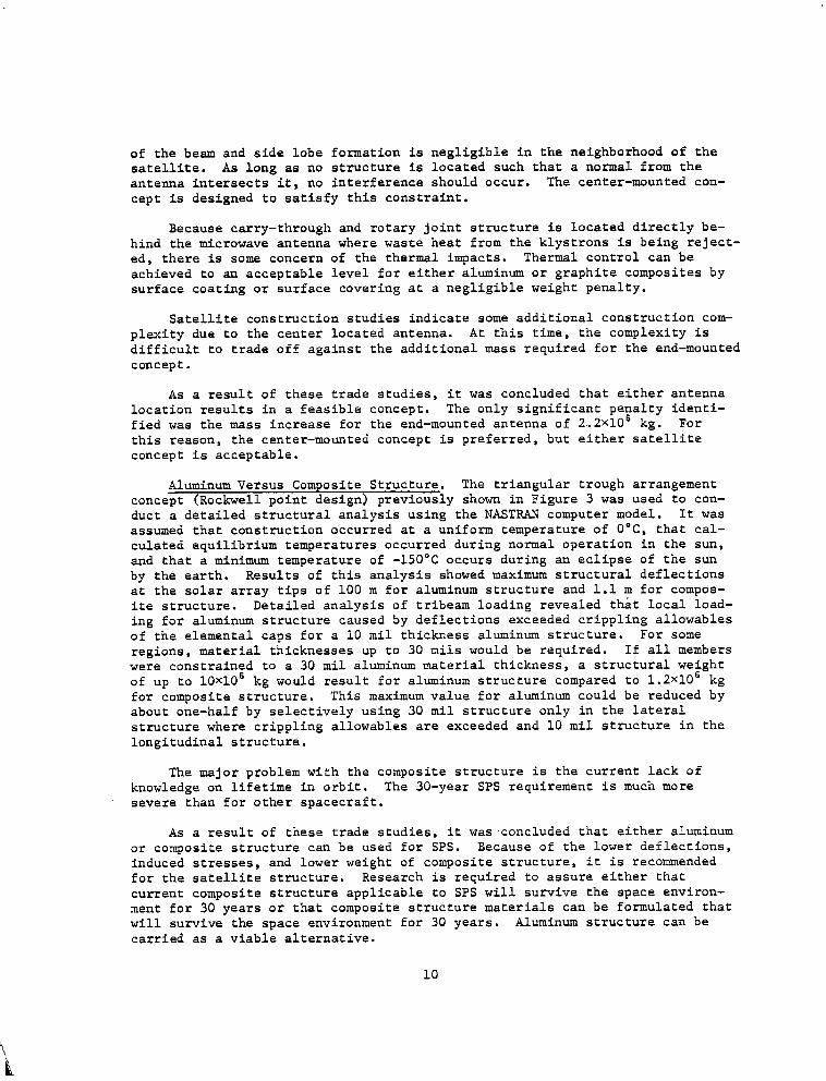
Antenna Structural Concept. Two concepts, shown in Figure 5, have been proposed for the antenna basic structure: a tension web, compression frame structure proposed by Rockwell and a spaceframe structure proposed by XC.
Figure 5. Alternative Antenna Structural Concepts
The tension web, compression frame structure is essentially like a tennis racket. The microwave antenna elements are attached to a square matrix formed by the composite tension web. Sufficient flatness is maintained against per- turbations by applying proper tension to the web. Loads from the web are carried in compression in the frame surrounding the web by catenary cables.
The spaceframe structure is a box-grid truss network. The microwave antenna elements are attached to the structure by a secondary supporting structure. Because of the large amount of study conducted under contract to JSC and internally at JSC, the characteristics of the spaceframe are well de- fined. The tension-web structure has not been sufficiently analyzed to assess the dynamic characteristics of the structure under annual cyclic loads. Such an analysis is needed to assure feasibility of the design. Estimates indicate that the tension web, compression frame structure has lower mass than the spaceframe structure. (0.067~10~ kg for the tension web compression frame com- pared to 0.250~10~ kg for the spaceframe.) Although a detailed analysis has not been accomplished, it is expected that construction may be faster and simpler for the tension web, compression frame structure.
One major area of difference for the two approaches is heating of the structures due to thermal radiation from the microwave antenna. The tension web does not see the thermal radiating elements of the antenna and can re- radiate solar heating from both sides; whereas, the spaceframe structure is directly below the antenna and is blocked by the antenna on one side for re- radiation. A thermal analysis revealed that the spaceframe structure would require high temperature composite structure (e.g., polyimide) to withstand the resulting temperatures.
11
Although the tension web, compression frame antenna structure has many potential advantages, sufficient analysis has not been accomplished to validate its feasibility for SPS. When appropriate, future studies of its dynamic characteristics should be accomplished to assess feasibility. The spaceframe should be continued as a baseline until these feasibility studies have been completed.
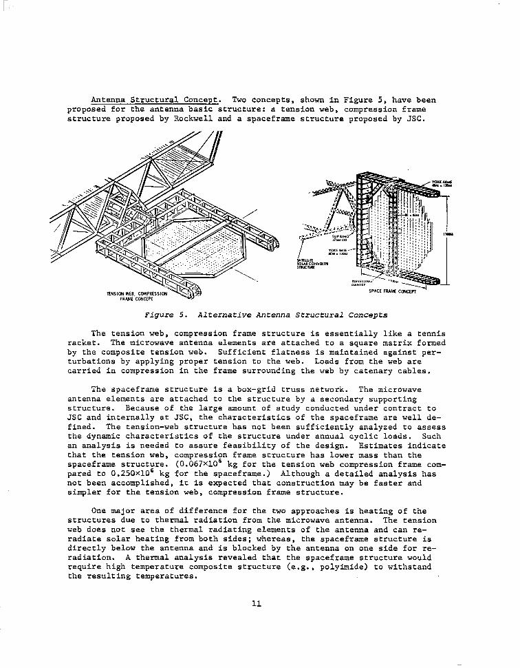
Alternate Rectenna Phased Arrays. Several rectenna phased array designs have been considered for application to SPS. Figure 6 compares the character- istics of these concepts. The number of elements in the array decrease from top to bottom in this figure. However, as the number of elements decrease, the aperature efficiency decreases. Of the concepts illustrated, the dense array, using stripline interconnections, is easiest to mass produce and install in addition to having a high efficiency. The dense array of stripline inter- connected dipoles is the recommended concept.
SHORT BACKF&
PARABOLIC TROUGH
CONCEPT
DENSE ARRAY InILLnOARO,
NUYSER OF
ELEMENTS ,s x I5 P AREAI OESCRIPT,ON COYYENTS
35Gu DIPOLES. A/2 SPACING STRlPLlllE ,NTEAcONNEcT 0.5% SWARE CLUSTERS OF MATCHING LOSS 49 ELEMENTS EOGE EFFECTS 1
NEEOS SW0
Al LOSS - 0.5% TO 5.5 KY
VAGI AWAY 4011 kSPAClNG. RECTANGULAR MUTUAL COUPLING CLUSTERSOF I? ELEMENTS EFFECT NEEDS STUOV
SHORT BACKFIRE ARRAY
TROUGH
WUARE PARABOLAS
2254
2205
540
ZASFACING.SOUARE BEAMWIDTH S,.,G”TLV CLUSTERSOF ELEMENTS TOO NARROWNEEDSSTUOV
Is PARABOLIC TROUGHS APERTURE EFFICIENCY VAGI FEEOSSPACEO k <BON
MO PARABOLAS APERTURE EFFICIENCY VAGI FE0 <Iox
PARABOLIC HORN
Figure 6. Alternative Rectenna Concepts
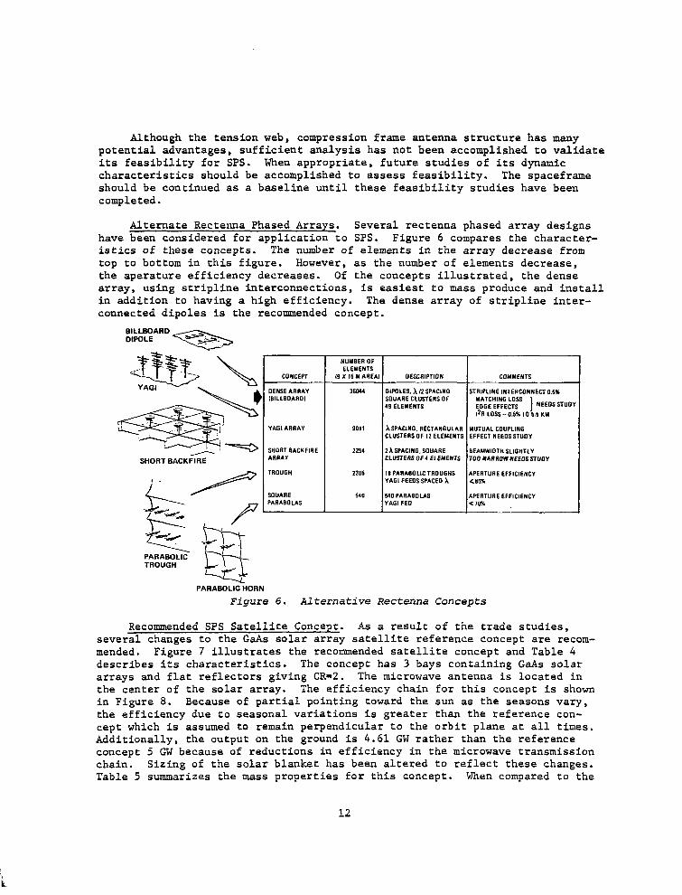
Recommended SPS Satellite Concept. As a result of the trade studies, several changes to the GaAs solar array satellite reference concept are recom- mended. Figure 7 illustrates the recommended satellite concept and Table 4 describes its characteristics. The concept has 3 bays containing GaAs solar arrays and flat reflectors giving CR=2. The microwave antenna is located in the center of the solar array. The efficiency chain for this concept is shown in Figure 8. Because of partial pointing toward the sun as the seasons vary, the efficiency due to seasonal variations is greater than the reference con- cept which is assumed to remain perpendicular to the orbit plane at all times, Additionally, the output on the ground is 4.61 GW rather than the reference concept 5 GW because of reductions in efficiency in the microwave transmission chain. Sizing of the solar blanket has been altered to reflect these changes. Table 5 summarizes the mass properties for this concept. When compared to the
12
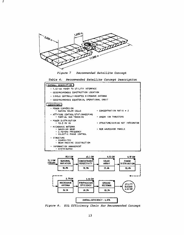
Figure 7 Recommended Satellite Concept
Table 4. Recommended Satellite Concept Description
OVERALL DESCRIPTION 1
. 4.61-GW POWER TO UTILITY INTERFACE
* GEOSYNCHRONOUS CONSTRUCTION LOCATION
. SINGLE CENTRALLY-MOUNTED MICROWAVE ANTENNA
. GEOSYNCHRONOUS EQUATORIAL OPERATIONAL ORBIT
. POWER CONVERSION . GaAlAs SOLAR CELLS ’ CONCENTRATION RATIO - 2
. ATTITUDE CONTROL/STATIONKEEPING - PARTIAL SUN TRACKING . ARGON ION THRUSTERS
. POWER DISTRIBUTION * 45.5 KV DC . STRUCTURE/WIRING NOT INTEGRATED
. MICROWAVE ANTENNA * GAUSSIAN BEAM . RCR WAVEGUIDE PANELS * 2.45-GHz FREQUENCY * ECLECTIC PHASE CONTROL
. STRUCTURE * COHPOS ITES . BEAM MACHINE CONSTRUCTION
. INFOPJIATION HANAGEMENT * DISTRIBUTED -.-- .-
69.0 GW 63.1 GW 9.53 GW 8.92 GW
71.3 GW 0 L # * m
SEASONAL CONCENTRATOR SOLAR (SOLARI
POWER - VARIATION + REFLECTIVITY + ARRAY - DISTRIBUTION
%.B% 91.5% 15.6% 93.6%
I t-
--- +---I
6.79 GW 5.53 GW s
MICROWAVE PROPAGATION k, ANTENNA - ffFICIi%CY + RECTENNA
76.1% 81.5%
I OVERALL EFFICIENCY - 6.47% I
Figure 8. EOL Efficiency Chain for Recommended Concept
13
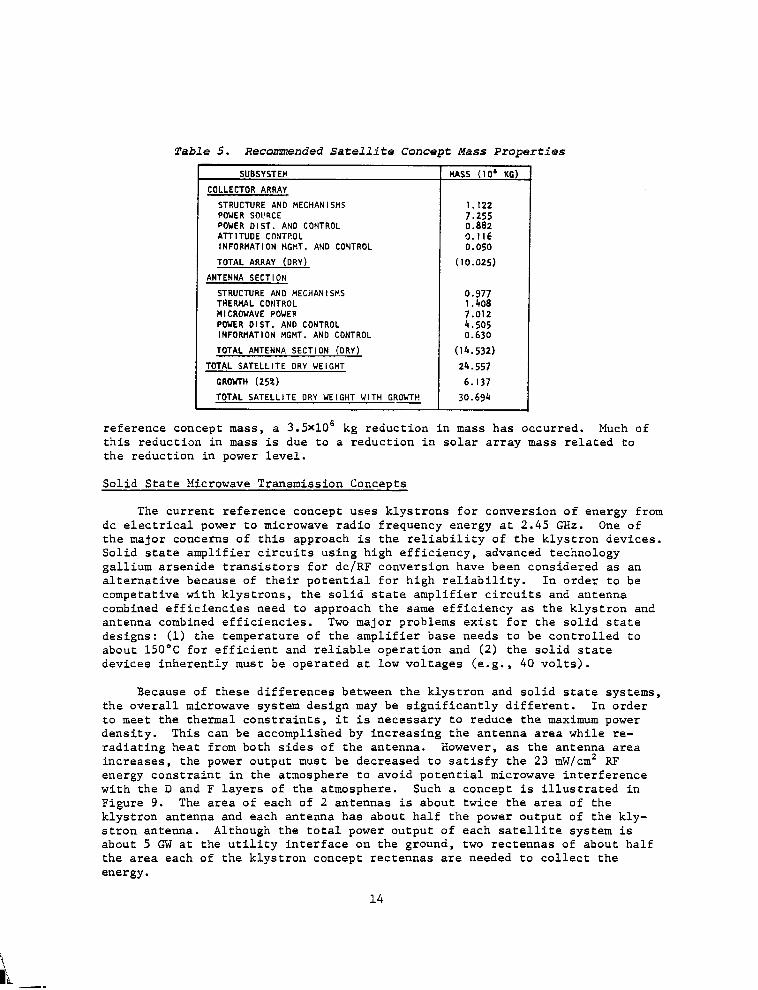
Table 5. Recommended Satellite Concept Mass Properties
COLLECTOR ARRAY
STRUCTURE AN0 MECHANISMS POWER SOL'RCE POWER DIST. AND CONTROL AlTlTUOE CONTROL INFORMATION HCHT. AND CONTROL
TDTAL ARRAY (DRY)
ANTENNA SECTION
1.122
zz iI16 0.050
(10.025)
STRUCTURE AND MECHANISMS 0.977 THERNAL CONTROL 1.408 MICROWAVE POWER 7.012 POWER DIST. AND CONTROL 4.505 INFORMATION MCI-IT. AND CONTROL 0.630
TOTAL ANTENNA SECTION (DRY) (14.532)
TOTAL SATELLITE DRY WEIGHT 24.557
CROYTH (25%) 6.137
TOTAL SATELLITE DRY WEIGHT WITH GRD'dTt! 30.694
reference concept mass, a 3.5x10⁶ kg reduction in mass has occurred. Much of this reduction in mass is due to a reduction in solar array mass related to the reduction in power level.
Solid State Microwave Transmission Concepts
The current reference concept uses klystrons for conversion of energy from dc electrical power to microwave radio frequency energy at 2.45 GHz. One of the major concerns of this approach is the reliability of the klystron devices. Solid state amplifier circuits using high efficiency, advanced technology gallium arsenide transistors for de/RF conversion have been considered as an alternative because of their potential for high reliability. In order to be competative with klystrons, the solid state amplifier circuits and antenna combined efficiencies need to approach the same efficiency as the klystron and antenna combined efficiencies. Two major problems exist for the solid state designs: (1) the temperature of the amplifier base needs to be controlled to about 150°C for efficient and reliable operation and (2) the solid state devices inherently must be operated at low voltages (e.g., 40 volts).
Because of these differences between the klystron and solid state systems, the overall microwave system design may be significantly different. In order to meet the thermal constraints, it is necessary to reduce the maximum power density. This can be accomplished by increasing the antenna area while re- radiating heat from both sides of the antenna. However, as the antenna area increases, the power output must be decreased to satisfy the 23 mW/cm' RF energy constraint in the atmosphere to avoid potential microwave interference with the D and F layers of the atmosphere. Such a concept is illustrated in Figure 9. The area of each of 2 antennas is about twice the area of the klystron antenna and each antenna has about half the power output of the kly- stron antenna. Although the total power output of each satellite system is about 5 GW at the utility interface on the ground, two rectennas of about half the area each of the klystron concept rectennas are needed to collect the energy.
14
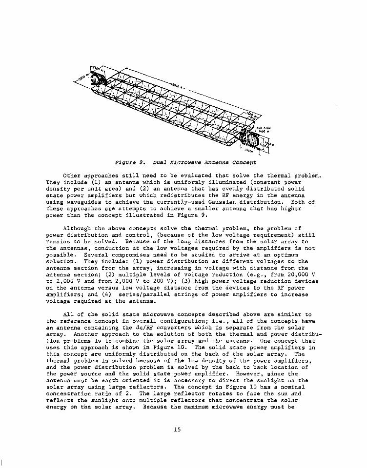
Figure 9. Dual Microwave Antenna Concept
Other approaches still need to be evaluated that solve the thermal problem. They include (1) an antenna which is uniformly illuminated (constant power density per unit area) and (2) an antenna that has evenly distributed solid state power amplifiers but which redistributes the RF energy in the antenna using waveguides to achieve the currently-used Gaussian distribution. Both of these approaches are attempts to achieve a smaller antenna that has higher power than the concept illustrated in Figure 9.
Although the above concepts solve the thermal problem, the problem of power distribution and control, (because of the low voltage requirement) still remains to be solved. Because of the long distances from the solar array to the antennas, conduction at the low voltages required by the ampl.ifiers is not possible. Several compromises need to be studied to arrive at an optimum solution. They include: (1) power distribution at different voltages to the antenna section from the array, increasing in voltage with distance from the antenna section; (2) multiple levels of voltage reduction (e.g., from 20,000 V to 2,000 V and from 2,000 V to 200 V); (3) high power voltage reduction devices on the antenna versus low voltage distance from the devices to the RF power amplifiers; and (4) series/parallel strings of power amplifiers to increase voltage required at the antenna.
All of the solid state microwave concepts described above are similar to the reference concept in overall configuration; i.e., all of the concepts have an antenna containing the de/RF converters which is separate from the solar array. Another approach to the solution of both the thermal and power distribu- tion problems is to combine the solar array and the antenna. One concept that uses this approach is shown in Figure 10. The solid state power amplifiers in this concept are uniformly distributed on the back of the solar array. The thermal problem is solved because of the low density of the power amplifiers, and the power distribution problem is solved by the back to back location of the power source and the solid state power amplifier. However, since the antenna must be earth oriented it is necessary to direct the sunlight on the solar array using large reflectors. The concept in Figure 10 has a nominal concentration ratio of 2. The large reflector rotates to face the sun and reflects the sunlight onto multiple reflectors that concentrate the solar energy on the solar array. Because the maximum microwave energy must be
15
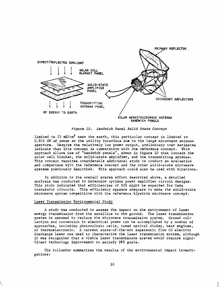
DIRECT/REFLECTED SUNLIGHT
ARY REFLECTORS TRANSMITTING ANTENNA PANEL
RF ENERGY TO EARTH / iOLAR ARRAY/MICROWAVE ANTENNA
SANDWICH PANELS
Figure 10. Sandwich Panel Solid State Concept
limited to 23 mW/cm2 near the earth, this particular concept is limited to 0.816 GW of power at the utility interface due to the large microwave antenna aperture. Despite the relatively low power output, preliminary cost estimates indicate that this concept is competitive with the reference concept. This approach allows use of "sandwich panels", shown in Figure 10 that contain the solar cell blanket, the solid-state amplifier, and the transmitting antenna. This concept requires considerable additional study to conduct an evaluation and comparison with the reference concept and the other solid-state microwave systems previously described. This approach could also be used with klystrons.
In addition to the overall system effort described above, a detailed analysis was conducted to determine optimum power amplifier circuit designs. This study indicated that efficiencies of 82% might be expected for GaAs transistor circuits. This efficiency appears adequate to make the solid-state microwave system competitive with the reference klystron microwave concept.
Laser Transmission Environmental Study
A study was conducted to assess the impact on the environment of laser energy transmission from the satellite to the ground. The laser transmission system is assumed to replace the microwave transmission system. Ground col- lection and conversion to electrical power can be accomplished by a number of approaches, includinp photovoltaic cells, tuned optical diodes, heat engines, or thermoelectronic. A current state-of-the-art supersonic flow CO electric discharge laser was used to characterize the laser transmission system, although it was recognized that a viable laser transmission system would require signi- ficant technology improvement to satisfy SPS goals.
The followinp summarizes the results of the environmental impact investi- gations:
16
l Global climatic change resulting from the proliferation of laser-SPS systems is highly improbable
l Mesoscale weather modifications at receptor locations will be less significant than such phenomena associated with conventional or nuclear electric power plants of comparable power rating
l Thermal heating of the lower troposphere by the laser beam will pro- mote waste-heat .dispersal by vertical mixing, but will also induce severe turbulence which could be hazardous to aircraft intruding into the restricted air zone
l The environmental impact on certain wildlife, especially birds and insects, is uncertain
l Laser-plasma interactions in the ionosphere are insignificant
l Laser-beam perturbation of the plasma chemistry in the mesophere and thermosphere is believed to be of negligible magnitude and con- sequence; however, confirming research is needed to substantiate this claim
l Serious environmental modifications, such as depletion of the ozone concentration in the stratosphere, are not possible
SPECIAL EMPHASIS STUDIES
Special emphasis studies were concentrated on a definition of satellite, satellite construction base, and rectenna construction. In addition, previous analyses of logistics were updated based on the system study results and further definition of the satellite construction base and the transportation sys tern. The results of these analyses are summarized in the following sections.
Satellite Construction
Satellite construction is assumed to occur entirely at geosynchronous orbit. Two 5 GW satellites are assumed to be built each year in building up a total capability of 60 satellites. The study of satellite construction was focused on determining the functions and the preferred conceptual approach for the satellite construction base (SCB).
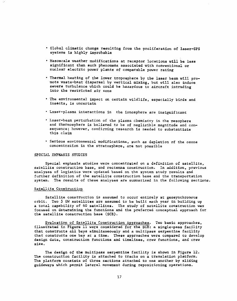
Evaluation of Satellite Construction Approaches. Two basic approaches, illustrated in Figure 11 were considered for the SCB: a single-pass facility that constructs all bays simultaneously and a multipass serpentine facility that constructs one bay at a time. These approaches were compared to develop design data, construction functions and timelines, crew functions, and crew size.
The design of the multipass serpentine facility is shown in Figure 12. The construction facility is attached to tracks on a translation platform. The platform consists of three sections attached to one another by sliding guideways which permit lateral movement during repositioning operations.
17
i
I MULTI-PASS SERPENTINE I
Figure 11. Satellite Construction Approaches
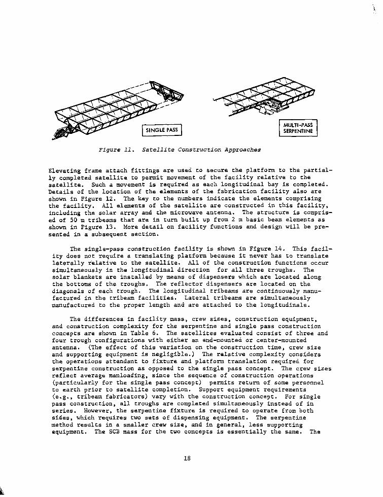
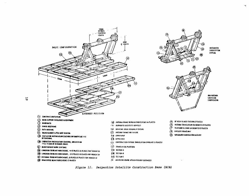
Elevating frame attach fittings are used to secure the platform to the partial- ly completed satellite to permit movement of the facility relative to the satellite. Such a movement is required as each longitudinal bay is completed. Details of the location of the elements of the fabrication facility also are shown in Figure 12. The key to the numbers indicate the elements comprising the facility. All elements of the satellite are constructed in this facility, including the solar array and the microwave antenna. The structure is compris- ed of 50 m tribeams that are in turn built up from 2 m basic beam elements as shown in Figure 13. More detail on facility functions and design will be pre- sented in a subsequent section.
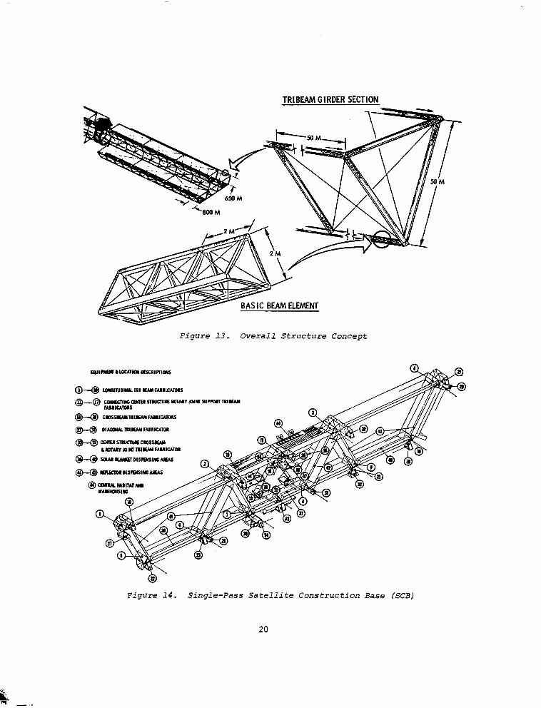
The single-pass construction facility is shown in Figure 14. This facil- ity does not require a translating platform because it never has to translate laterally relative to the satellite. All of the construction functions occur simultaneously in the longitudinal direction for all three troughs. The solar blankets are installed by means of dispensers which are located along the bottoms of the troughs. The reflector dispensers are located on the diagonals of each trough. The longitudinal tribeams are continuously manu- factured in the tribeam facilities. Lateral tribeams are simultaneously manufactured to the proper length and are attached to the longitudinals.
The differences in facility mass, crew sizes, construction equipment, and construction complexity for the serpentine and single pass construction concepts are shown in Table 6. The satellites evaluated consist of three and four trough configurations with either an end-mounted or center-mounted antenna. (The effect of this variation on the construction time, crew size and supporting equipment is negligible.) The relative complexity considers the operations attendant to fixture and platform translation required for serpentine construction as opposed to the single pass concept. The crew sizes reflect average manloading, since the sequence of construction operations (particularly for the single pass concept) permits return of some personnel to earth prior to satellite completion. Support equipment requirements (e.g., tribeam fabricators) vary with the construction concept. For single pass construction, all troughs are completed simultaneously instead of in series. However, the serpentine fixture is required to operate from both sides, which requires two sets of dispensing equipment. The serpentine method results in a smaller crew size, and in general, less supporting equipment. The SCB mass for the two concepts is essentially the same. The
18
a;zN . . . -- ---CLNlROID h
BASIC COHFlCURATlOH
~XTENOEO POSITION
(Ejl ANILNMFfRA~1RIR~~fABRICAIOR5I~RACfSI
iPl IHIRAaAYLOClSllCS VfIIIClIS
(10) RUIAlING JOIN1 ASSLMULY IIXIURL
@ ANIlNNAIRA.tFAOIlXlURt
@ ZWUCIOR lNSlYUllWSIAIIOWS011~RSIIYI~Xt rig LOWI VALF
WDIACNLM LfTlj UPRllnAlf
@ 2fIffUtlOYlNSfAllAllW SIAIIWS, WMCHW 'Y 1 .V SIM ti DIAClVlAA BRACl
@ WfABIINSIMRK SIAIIWS
0 t~fWlRl~fAIRltAIOftS. l Y~~~~ACESI~~~AC~S~OR~RWC~~~I,
@ kwcmd ~~~~iAIRl~AkIfts. -Y II mu5 I5 PUCLS fOR IROUGH 111
(w) D~AUW~R~YAY~ARRICAIOIIS.I?RAC~SI~PUCLS~ORIRUUC~~ ,,I
@ lRAllSVlilS4 AlAH fAIRICAM)RS (I AACtSl
QJ COHSIRUCIION~IXI~JRI lRANSlAllONCAWRIAff II FlACfSJ
'(3 IRfflSlAIION PLAIFORM
@l SLCIIONA
@I) StCllONa
p9 SLCIIWC
$4 WAIINC fRAY AffACHflfflHGllI PLACLSI
INIfCRATED FAURICMIW FIxTutlE
fAIRlCAUON
$j RF ASSYAlNSlSIAIIfflIZPLACfSI
16
8
ANT~NM IRANSWIN ~UIOLWAVS 12 RACLSI
II PLATFORMSLIDINGGUIMWAYSI~PLAC~SI
@ fACfufYlR~vtt~~Y
@ l~lt~A~DfAIRICAIIfflf)iCllllY
Figure 12. Serpentine Satellite Construction Base (SCB)
TRIBEAh GIRDER SECTION
Figure 13. Overall Structure Concept
Figure 14. Single-Pass Satellite Construction Base (SCB)
20
&& - .
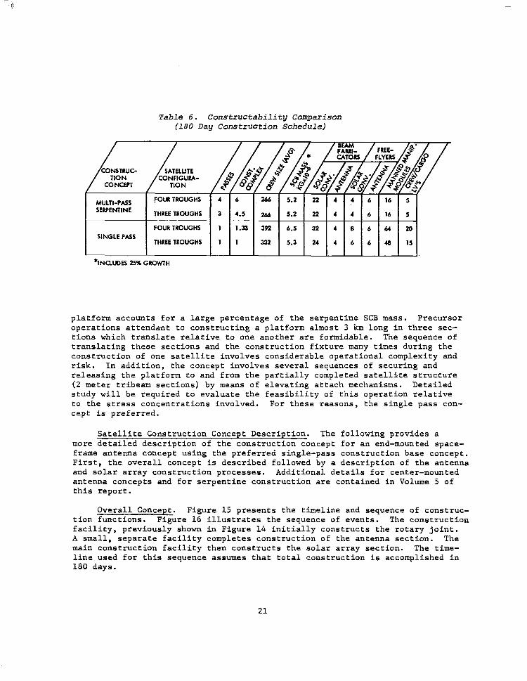
Table 6. Constructability Comparison (180 Day Construction Schedule)
/ CON5TRUC- TION CONCEPT
- .-.v
MULTI-PASS FOull TROUGHS 4 6 266 5.2 22 4 4 6 16 5
SERPENTINE THREE TROUGHS 3 4.5 266 5.2 22 4 4 6 16 5
FOUR TROUGHS 1 1.33 392 6.5 32 4 8 6 64 20 t SINGLE PASS
I THREE TROUGHS 1 1 1 1 1 332 1 5.3 1 24 1 4 1 6 1 6 1 43 1 15 1
*INaUDES 25% GROWTH
platform accounts for a large percentage of the serpentine SCB mass. Precursor operations attendant to constructing a platform almost 3 km long in three sec- tions which translate relative to one another are formidable. The sequence of translating these sections and the construction fixture many times during the construction of one satellite involves considerable operational complexity and risk. In addition, the concept involves several sequences of securing and releasing the platform to and from the partially completed satellite structure (2 meter tribeam sections) by means of elevating attach mechanisms. Detailed study will be required to evaluate the feasibility of this operation relative to the stress concentrations involved. For these reasons, the single pass con- cept is preferred.
Satellite Construction Concept Description. The following provides a more detailed description of the construction concept for an end-mounted space- frame antenna concept using the preferred single-pass construction base concept. First, the overall concept is described followed by a description of the antenna and solar array construction processes. Additional details for center-mounted antenna concepts and for serpentine construction are contained in Volume 5 of this report.
Overall Concept. Figure 15 presents the timeline and sequence of construc- tion functions. Figure 16 illustrates the sequence of events. The construction facility, previously shown in Figure 14 initially constructs the rotary joint. A small, separate facility completes construction of the antenna section. The main construction facility then constructs the solar array section. The time- line used for this sequence assumes that total construction is accomplished in 180 days.
21
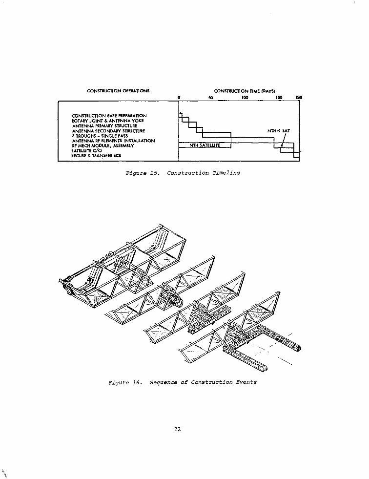
CONSTRUCTlON OPERATlONS
I CONSTRUCTION BASE PREPARAllON ROTARY JOINT 6 ANTENNA YOKE ANTENNA PRMARY STRUCTURE ANTENNA SECONDARY STRUCTURE 3 TROUGHS - SINGLE PASS
I ANTENNA RF ELEMENTS INSTALLATION RF MECH MODULE, ASSEMBLY SATELLITE UO SECURE 6. TRANSFER SC3
CONSTRUCTlON TIME (DAYS) 50 ml Is0 1
Figure 15. Construction Timeline
D
Figure 16. Sequence of Construction Events
22
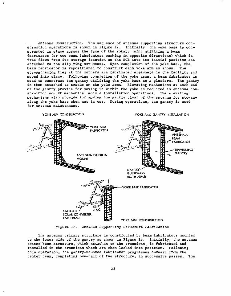
Antenna Construction. The sequence of antenna supporting structure con- struction operations is shown in Figure 17. Initially, the yoke base is con- structed in place across the face of the rotary joint utilizing a beam fabricator (or two beam fabricators working in opposite directions) which is free flown from its storage location on the SCB into its initial position and attached to the slip ring structure. Upon completion of the yoke base, the beam fabricator is repositioned to construct each yoke arm as shown. The strengthening ties at the corners are fabricated elsewhere in the facility and moved into place. Following completion of the yoke arms, a beam fabricator is used to construct the gantry utilizing the yoke base as a platform. The gantry is then attached to tracks on the yoke arms. Elevating mechanisms at each end of the gantry provide for moving it within the yoke as required in antenna con- struction and RF mechanical module installation operations. The elevating mechanisms also provide for moving the gantry clear of the antenna for stowage along the yoke base when not in use. During operations, the gantry is used for antenna maintenance.
YOKE ARM CONSTRUCTION
-2 ‘:A .“: _.. _- __--
ANTENNA TRUNION
YOKE AND GANTRY INSTALLATION
(BOTH ARMS)
YOKE BASE FABRICATOR
SOLAR CONVERTER END FRAME
YOKE BASE CONSTRUCTION
Figure 17. Antenna Supporting Structure Fabrication
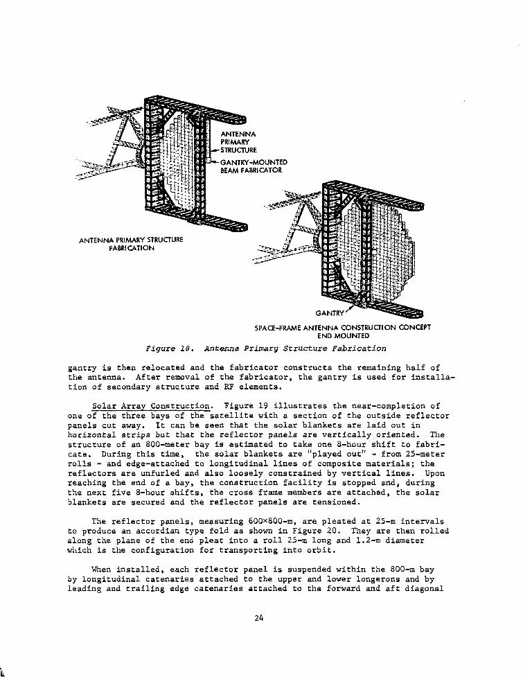
The antenna primary structure is constructed by beam fabricators mounted to the lower side of the gantry as shown in Figure 18. Initially, the antenna center beam structure, which attaches to the trunnions, is fabricated and installed in the trunnions which are then locked into position. Following this operation, the gantry-mounted fabricator progresses outward from the center beam, completing one-half of the structure, in successive passes. The
23
GANTRY-MOUNTED BEAM FABRICATOR
ANTENNA PRIMARY STRUCTURE FABRICATION
SPACE-FRAME ANTENNA CONSTRUCTION CONCEPT END MOUNTED
Figure 18. Antenna Primary Structure Fabrication
gantry is then relocated and the fabricator constructs the remaining half of the antenna. After removal of the fabricator, the gantry is used for installa- tion of secondary structure and RF elements.
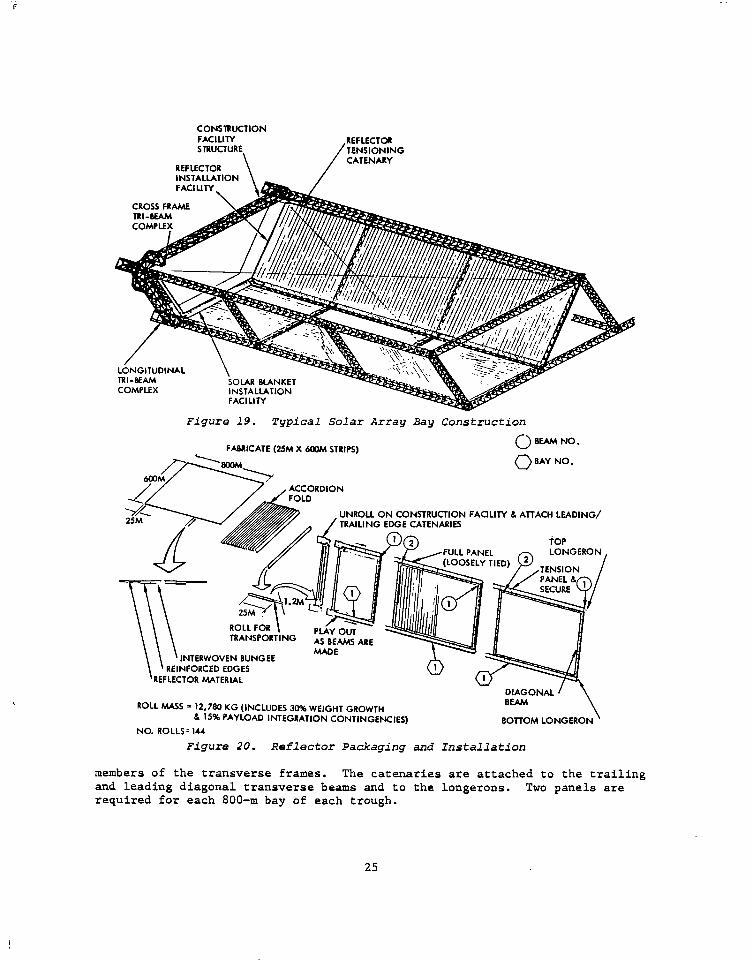
Solar Array Construction. Figure 19 illustrates the near-completion of one of the three bays of the satellite with a section of the outside reflector panels cut away. It can be seen that the solar blankets are laid out in horizontal strips but that the reflector panels are vertically oriented. The structure of an SOO-meter bay is estimated to take one S-hour shift to fabri- cate. During this time, the solar blankets are "played out" - from 25-meter rolls - and edge-attached to longitudinal lines of composite materials; the reflectors are unfurled and also loosely constrained by vertical lines. Upon reaching the end of a bay, the construction facility is stopped and, during the next five S-hour shifts, the cross frame members are attached, the solar blankets are secured and the reflector panels are tensioned.
The reflector panels, measuring 600x800-m, are pleated at 25-m intervals to produce an accordian type fold as shown in Figure 20. They are then rolled along the plane of the end pleat into a roll 25-m long and 1.2-m diameter which is the configuration for transporting into orbit.
When installed, each reflector panel is suspended within the 800-m bay by longitudinal catenaries attached to the upper and lower longerons and by leading and trailing edge catenaries attached to the forward and aft diagonal
24
CONSTRUCTION FACILITY STRUCTURE. /K.ZEG
LbNGITUDINAL TRI-BEAM
\ SOLAR BLANKET Y
Figure 19. Typical Solar Array Bay Construction
0 BEAM NO. FABRICATE (25M X WOM STRIPS)
0 BAY NO.
ONSTRUCTION FAaLllY d, ATTACH LEADING/ E CATENARIES
fop
ROLL wS = w80 KG (INCLUDES 30% WEIGHT GROWTH h 6% PAYLOAD INTEGRATION CONTINGENCIES) BOlTOM LONGER0
NO. ROLLS = 144
Figure 20. Reflector Packaging and Installation
members of the transverse frames. The catenaries are attached to the trailing and leading diagonal transverse beams and to the longerons. Two panels are required for each 800-m bay of each trough.
25
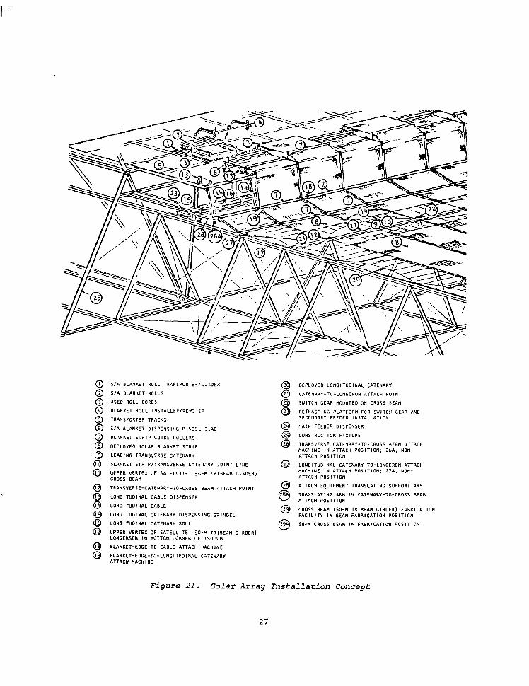
Figure 21 shows the installation concept for the solar cell blanket. The solar blanket in each 800 m long bay is a structurally independent installation suspended by side and end catenaries attached to the longerons and cross beams, respectively, and by longitudinal cables stretched between the blanket strips. Each blanket strip is approximately 25 m wide and 750 m long, and is packaged in a 25 m wide roll by 0.6 m in diameter. Each two bays of solar blankets are electrically connected in series, constituting a functional module which pro- duces the required voltage.
Initially the blanket rolls are transported from the SCB warehouse area by a transporter/loader (1) which inserts the rolls into the dispensers (6). The leading edge of the blanket strips, with end catenaries attached, are then threaded through the roller arrangement and attached to the trailing edge of the completed crossbeam. The longitudinal cables to which the side edges of the blanket will be fastened are threaded from the cable dispenser (13) and attached in a similar manner. The longitudinal catenaries are fabricated on the middle deck, fed into the dispensing spindle (15) and then attached to the crossbeam trailing edge.
Solar blankets and catenaries are attached to the longitudinal cables by foldover tabs which are applied by automatic fastening equipment. As the cross- beam advances the blanket strips, longitudinal catenaries and cables are payed out. The two outside cables are attached to the longitudinal catenaries, the two longitudinal catenaries to their respective longerons, and the inside edges of adjacent blanket strips to their stabilizing cables. Upon completion of the bay and the next following crossbeam, the trailing edges of the blankets (i.e., the trailing transverse catenaries) and the trailing end of the longitudinal catenaries are attached to the leading edge of that crossbeam. The installa- tion is then tensioned and electrical connections completed.
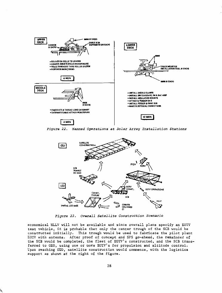
The primary operations occurring at the upper, middle, and iower deck stations during beam fabrication and solar array installation are identified in Figure 22. The locations of the manned manipulator modules (MM) required to support the installations also are shown. These modules are mounted on transverse tracks and are spaced so that each module services approximately one-fourth of the 27 installation stations across the span of the crossbeam. Approximately 600 men are required, on the average, to operate the SCB.
Satellite Construction Base Construction
Because of the large size of the SCB, it is necessary to define the approach to its construction starting with the basic space shuttle resources and elements that can be brought up from earth in the shuttle. A detailed study of this pro- cess was conducted, including an overview of the total build-up to start the satellite construction process at geosynchronous orbit.
The overall sequence of events is illustrated in Figure 23. The initial step in satellite precursor operations is establishment of a LEO base as shown in the lower left of the figure. Crew and power modules are transported to LEO by Shuttle derivatives and assembled. When the base is fully operational, Shuttle external tanks are delivered and mated to form construction fixtures for SCB construction. Figure 23 shows a completed SCB. Since the more
26
S/A BLANKET ROLL TRANSPORTE’.‘:lAOEQ
S/A BLANKET ROLLS
USED ROLL CORES
BLANKET ROLL INSTALLER,RE”~.:’
TRANSPORTER TRACKS
S/A BLANKET OlSPENSIHG Pl’iOEi ,.A0
BLANKET STRIP GUIDE ROLLE?S
OEPLOYEO SOLAR BLANKET STR,?
LEAOING TRANSVERSE CATENAR”
BLANKET STRIP,TRANSYERSE CGTEXRY JOINT LlNE
UPPER VERTEX OF SATELLITE j;-W TRIBEW GIRDER) CROSS BEAN
TRANSVERSE-CATEHARY-TO-CROSS 33~ ATTACH POINT
LONGITUDINAL CABLE DISPENSER
LONCITUOINAL CABLE
LONGITUDINAL CATENARY DISPENSIYG SPlNOEL
LONGITUDINAL CATENARY ROLL
UPPER VERTEX OF SATELLITE ,jO-M TRIBEAM GIROER) LONGERSOY IN BOTTO!, CORNER OF TSOUGH
BLANKET-EDGE-TO-CABLE ATTACH *ACHINE
BLANKET-EDGE-TO-LONGITUDINAL CGTEWRY ATTACH HACHINE
DEPLOYED LONGITUOINAL CATENARY
CATENARY-TO-LONGERON ATTACH POINT
SWITCH GEAR MOUNTED ON CROSS BEAM
RETRACTING PLATFORM FOR SWITCH GEAR AN0 SECONDARY FEEDER INSTALLATION
MIN FEEDER DISPENSER
CONSTRUCTlOb, FIXTURE
TRANSVERSE CATENARY-TO-CROSS BEAM ATTACH “ACHINE IN ATTACH POSITION: 26A. NON- ATTACH POSITION
LONCITUOINAL CATENARY-TO-LONGERON ATTACH MACHINE IN ATTACH POSITION: 27A. NON- ATTACH POSITION
ATTACH EQUIPMENT TRANSLATING SUPPORT ARH
TRANSLATING AR,, IN CATENARY-TO-CROSS BEA” ATTACH POSITION
CROSS BEA” (50-M TRIBEAM GIRDER) FABRICATION FACILITY IN BEAM FABRICATION POSITION
50-M CROSS aEAt4 IN FABRlCATlDn POSITION
Figure 21. Solar Array Installation Concept
27
. DELIVER .S4 ROLLS TO LOADER
. LOAOE” lN.5ERl-S ROLLS IN DISPENSERS
. ROLIS THREAOEO THR” ROLLER SYSTEM . OWENSEll VONI~ORINC
. FMRKATE 8 TnREAO LONG CITENARY
.CATEMARY,CAILE A,TACH YONlTORlNG
ME0 ON TOOL I4 EACH1
. INSTALL SADDLE ClAYrS
. INSTALL SWITCH GEARI. SY h RAC hW
. INSTALL IWSUUYION MOUNTS
.A~TACHLTENSIONSA~
. INSTALL FEEDER 6 OY&C BUS
. MAKE ELECTRICAL CONNECTIONS
Figure 22. Manned Operations at Solar Array Installation Stations
Figure 23. Overall Satellite Construction Scenario
economical HLLV will not be available and since overall plans specify an EOTV test vehicle, it is probable that only the center trough of the SCB would be constructed initially. This trough would be used to fabricate the pilot plant EOTV with antenna. After proof of concept and SPS go-ahead, the remainder of the SCB would be completed, the fleet of EOTV's constructed, and the SCB trans- ferred to GEO, using one or more EOTV's for propulsion and altitude control. Upon reaching GEO, satellite construction would commence, with the logistics support as shown at the right of the figure.
28
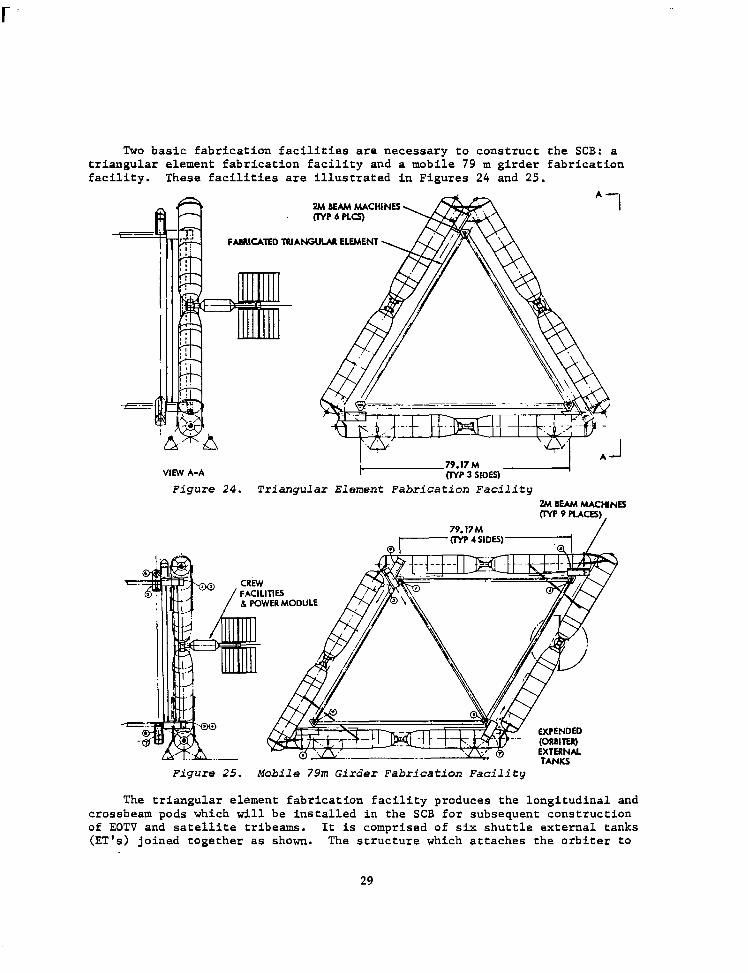
Two basic fabrication facilities are necessary to construct the SCB: a triangular element fabrication facility and a mobile 79 m girder fabrication facility. These facilities are illustrated in Figures 24 and 25.
Zh4 BEAM MACHINE.5 crvp6pLcs)
FMWZATED TRIANGULM ELEMENT
VIEW A-A
Figure 24. Triangular Element Fabrication Facility L?h+ IttAM htACHlNES (IYP 9 PLACES)
79.17M -crvP4SIDW- /
______k -
TANKS
Y EXPENDED ~,~,,: n’ -.- (ORBIW
EXTERNAL
Figure 25. Mobile 79m Girder Fabrication Facility
The triangular element fabrication facility produces the longitudinal and crossbeam pods which will be installed in the SCB for subsequent construction of EOTV and satellite tribeams. It is comprised of six shuttle external tanks (ET'S) joined together as shown. The structure which attaches the orbiter to
29
the aft section of the ET is utilized for joining the ET's and is augmented by prefabricated bracing delivered by the orbiter. A triangular element comprised of 2 meter tribeams is mounted within the triangle formed by the ET's and pro- vides the structure required for mounting the 2 meter beam machines which are used for constructing the outer triangle of the tribeam pod, or fabricator. A total of six beam machines are required; three for longitudinal beams and three for crossbeams. Crew facilities and power module, shown at the left of the figure, provides crew habitat and the electrical power required to operate life support and the beam machines. Reaction control pods attached to the ET's pro- vide the required altitude control.
The primary structure of the SCB consists of a diamond cross section formed by two triangles. A mobile diamond-shaped fixture formed by joining 8 orbiter external tanks is utilized for SCB primary structure fabrication. The beam machines are located at the tips of the structure enclosed by the external tanks. Nine machines are required to construct the four longerons, the four crossbeams and the diagonal beam. A combination crew and power module provides crew facilities and electrical power.
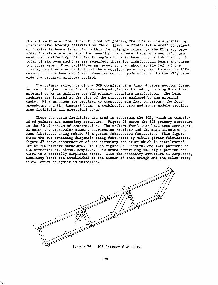
These two basic facilities are used to construct the SCB, which is compris- ed of primary and secondary structure. Figure 26 shows the SCB primary structure in the final phases of construction. The tribeam facilities have been construct- ed using the triangular element fabrication facility and the main structure has been fabricated using mobile 79 m girder fabrication facilities. This figure shows the two remaining diagonals being fabricated by mobile girder fabricators. Figure 27 shows construction of the secondary structure which is cantilevered off of the primary structure. In this figure, the central and left portions of the structure are almost complete. The beams comprising the right portion are shown in a partially completed state. When the secondary structure is completed, auxiliary bases are established at the bottom of each trough and the solar array installation equipment is installed.
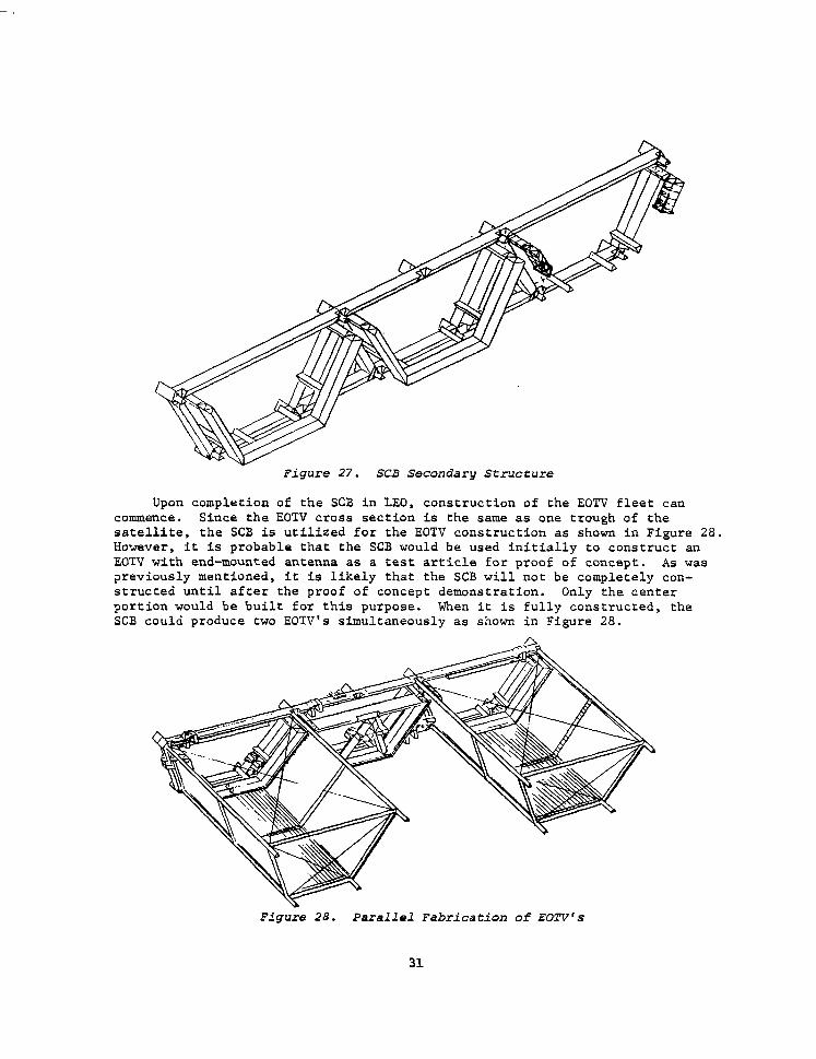
Figure 27. SCB Secondary Structure
Upon completion of the SCB in LEO, construction of the EOTV fleet can commence. Since the EOTV cross section is the same as one trough of the satellite, the SCB is utilized for the EOTV construction as shown in Figure 28. However, it is probable that the SCB would be used initially to construct an EOTV with end-mounted antenna as a test article for proof of concept. As was previously mentioned, it is likely that the SCB will not be completely con- structed until after the proof of concept demonstration. Only the center portion would be built for this purpose. When it is fully constructed, the SCB could produce two EOTV's simultaneously as shown in Figure 28.
Figure 28. Parallel Fabrication of EOTV's
31
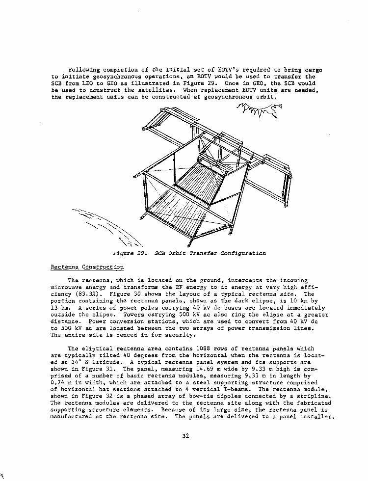
Following completion of the initial set of EOTV's required to bring cargo to initiate geosynchronous operations, an EOTV would be used to transfer the SCB from LEO to GE0 as illustrated in Figure 29. Once in GEO, the SCB would be used to construct the satellites. When replacement EOTV units are needed, the replacement units can be constructed at geosynchronous orbit.
Rectenna Construction
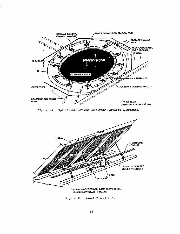
The rectenna, which is located on the ground, intercepts the incoming microwave energy and transforms the RF energy to dc energy at very high effi- ciency (83.3%). Figure 30 shows the layout of a typical rectenna site. The portion containing the rectenna panels, shown as the dark elipse, is 10 km by 13 km. A series of power poles carrying 40 kV dc buses are located immediately outside the elipse. Towers carrying 500 kV ac also ring the elipse at a greater distance. Power conversion stations, which are used to convert from 40 kV dc to 500 kV ac are located between the two arrays of power transmission lines. The entire site is fenced in for security.
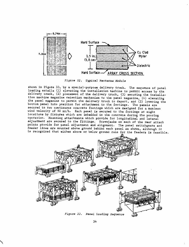
The eliptical rectenna area contains 1088 rows of rectenna panels which are typically tilted 40 degrees from the horizontal when the rectenna is locat- ed at 34" N latitude. A typical rectenna panel system and its supports are shown in Figure 31. The panel, measuring 14.69 m wide by 9.33 m high is com- prised of a number of basic rectenna modules, measuring 9.33 m in length by 0.74 m in width, which are attached to a steel supporting structure comprised of horizontal hat sections attached to 4 vertical I-beams. The rectenna module, shown in Figure 32 is a phased array of bow-tie dipoles connected by a stripline. The rectenna modules are delivered to the rectenna site along with the fabricated supporting structure elements. Because of its large size, the rectenna panel is manufactured at the rectenna site. The panels are delivered to a panel installer,
32
500 Kvic MIS (IYr .) I w”ASEe WL.. .. L
‘OWER CONVERSION STATION (nr)
USER (TYP.) @-PHASE,
?T-- \ MONITOR L COMROL FACIUTY
NOT TO SCALE (PANEL AREA lo Kh4 X 13 KM)
Figure 30. Operational Ground Receivhg Facility (Rectema)
I \0.31~ WIDE FOOTING, o.lsM ABOVE GRADE.
O&M BELOW GRADE @ PLACES)
Figure 31. Panel Installation
33
Hard Surface y
1.5 in (3.8 cm
1
Cu Clad Mylar
*Dielectric
Hard SurfacelARRAY CROSS SECTION
Figure 32. Typical Rectenna Module
shown in Figure 33, by a special-purpose delivery truck. The sequence of panel loading entails (1) elevating the installation machine to permit access by the delivery truck, (2) placement of the delivery truck, (3) securing the installa- tion machine magazine retention mechanism to the panel magazine, (4) elevating the panel magazine to permit the delivery truck to depart, and (5) lowering the bottom panel into position for attachment to the footings. The panels are secured to two continuous concrete footings which are designed for a maximum wind velocity of 90 mi/h. Each panel is secured to the footings at eight locations by fixtures which are imbedded in the concrete during the pouring operation. Mounting attachments which provide for longitudinal and lateral adjustment are secured to the fittings. Screwjacks on each of the rear attach points provide for panel adjustment and alignment. The panel switchgears and feeder lines are mounted above ground behind each panel as shown, although it is recognized that either above or below ground runs for the feeders is feasible.
Figure 33. Panel Loading Sequence
34
r
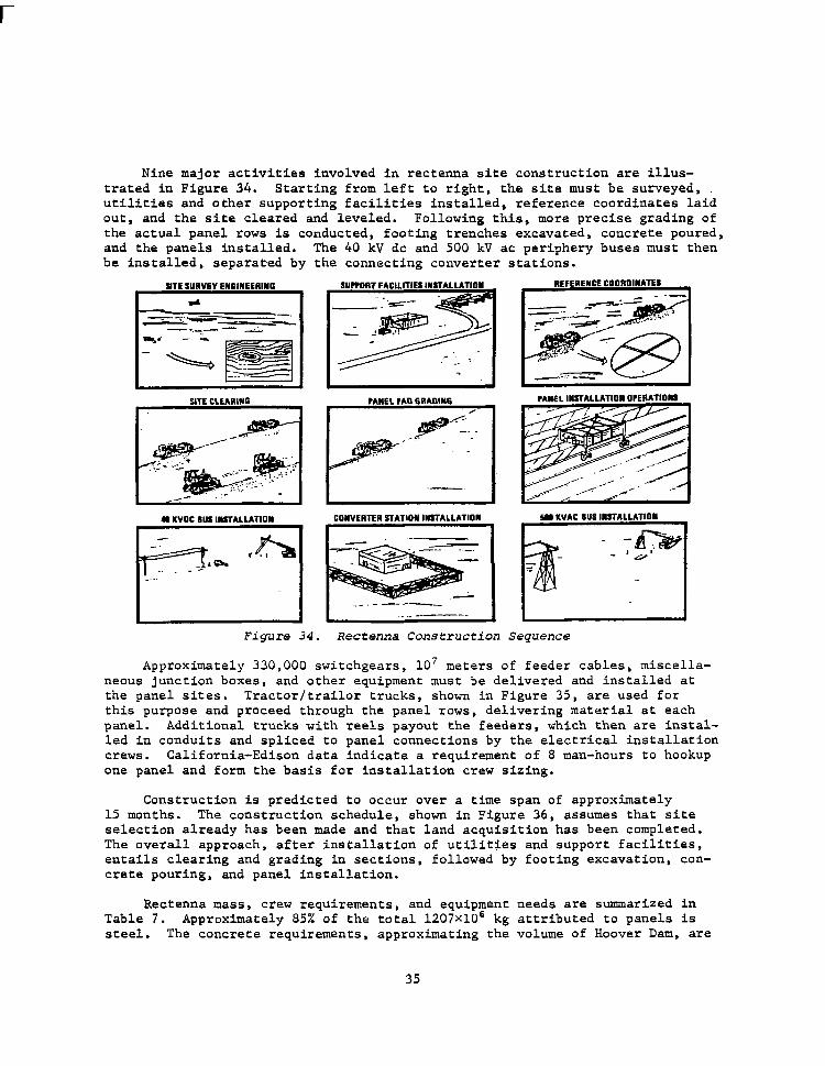
Nine major activities involved in rectenna site construction are illus- trated in Figure 34. Starting from left to right, the site must be surveyed, utilities and other supporting facilities installed, reference coordinates laid out, and the site cleared and leveled. Following this, more precise grading of the actual panel rows is conducted, footing trenches excavated, concrete poured, and the panels Installed. The 40 kV dc and 500 kV ac periphery buses must then be installed, separated by the connecting converter stations.
STE SURVEY EN6lNEEGlNG
SITE CLEARING I
~~~~ El.
PANEL INSTALLATION OPERATIONS
I
44 KVOC SUS INSTALLATION CONVERTER STATION INSTALLATION I
I . ---- I
5SS KVAC SIJS IN3TALLATION
Figure 34. Rectenna Construction Sequence
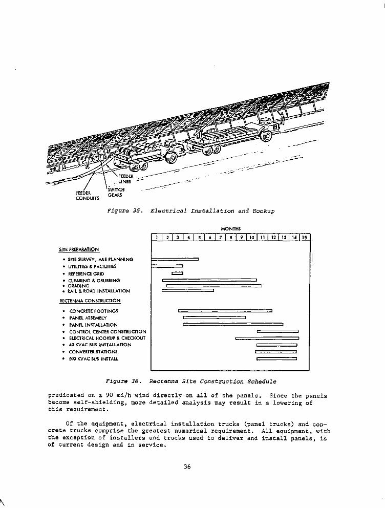
Approximately 330,000 switchgears, 107 meters of feeder cables, miscella- neous junction boxes, and other equipment must be delivered and installed at the panel sites. Tractor/trai.lor trucks, shown in Figure 35, are used for this purpose and proceed through the panel rows, delivering material at each panel. Additional trucks with reels payout the feeders, which then are instal- led in conduits and spliced to panel connections by the electrical installation crews. California-Edison data indicate a requirement of 8 man-hours to hookup one panel and form the basis for installation crew sizing.
Construction is predicted to occur over a time span of approximately 15 months. The construction schedule, shown in Figure 36, assumes that site selection already has been made and that land acquisition has been completed. The overall approach, after installation of utilities and support facilities, entails clearing and grading in sections, followed by footing excavation, con- crete pouring, and panel installation.
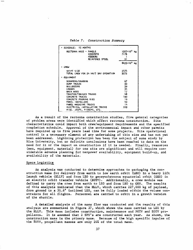
Rectenna mass, crew requirements, and equipment needs are summarized in Table 7. Approximately 85% of the total 1207~10~ kg attributed to panels is steel. The concrete requirements, approximating the volume of Hoover Dam, are
35
/ FEEDER
‘iWITCH
CONDUITS GEARS
Figure 35. Electrical Installation and Hookup
SITE PREPARATION
l SITE SURVEY, A&E PLANNING l UTILITIES 6 FACILITIES
l REFERENCE GRID l CLEARlNG 6 GRUBBING l GRADING . RAIL 6 ROAD INSTALLATION
RECTENNA CONSTRUCTION
l CONCRETE FOOTINGS . PANEL ASSEMBLY l PANEL INSTALLATION l CONTROL CENTER CONSTRUCTION l ELECTRICAL HOOKUP 6 CHECKOUT l 40 KVAC BUS INSTALLATION
l CONVERTER STATIONS l 500 KVAC BUS INSTALL
MONTHS
1 1 2 1 3 1 4 1 5 1 6 1 7 1 a 1 9 I10 I 11 I 12 I 13 I 14 I l!
I
I I 1
I 1 I I
I 1
I I
L 1
Figure 36. RecteMa Site Construction Schedule
predicated on a 90 mi/h wind directly on all of the panels. Since the panels become self-shielding, more detailed analysis may result in a lowering of this requirement.
Of the equipment, electrical installation trucks (panel trucks) and con- crete trucks comprise the greatest numerical requirement. All equipment, with the exception of installers and trucks used to deliver and install panels, is of current design and in service.
36
-
Table 7. Construction Summary
* SCHEDULE: 15 t4ONTHS
RECTENNA MASS - PANELS CONCRETE FEEDERS REINFORCE STEEL
SHIFT SIZE 2474 TOTAL CREW FOR 24 HR/7 DAY OPERATION 9272
* EQU I PHENT
SCRAPERS/GRADERS DUMP TRUCKS BULLDOZERS CRANES BACK HOES TRACTOR/TRAILER TRUCKS CONCRETE TRUCKS CONCRETE POURING RIGS PANEL INSTALLERS PANEL HAGAZINE TRUCKS ELECTRICAL INSTALLATION TRUCKS MISC. JEEPS, PICKUPS. ETC. ___-
40 14
229
1207~10~ kg 7176
5:
8435x10' kg
As a result of the rectenna construction studies, five general categories of problem areas were identified which affect rectenna construction. Site characteristics could impact both crew/equipment requirements and the specified completion schedule. Approval of the environmental impact and other permits have required up to five years lead time for some projects. Site operational control is a necessary element of any undertaking of this size and has not yet been addressed. Lightning protection has been the subject of some study by Rice University, but no definite conclusions have been reached to .date on the need for it or the impact on construction if it is needed. Finally, resources hen, equipment, material) for one site are significant and will require con- siderable advance planning for manpower availability, equipment build-up, and availability of the materials.
Space Logistics
An analysis was conducted to determine approaches to packaging the con- struction mass for delivery from earth to low earth orbit (LEO) in a heavy lift launch vehicle (HLLV) and from LEO to geosynchronous equatorial orbit (GEO) in an electric orbit transfer vehicle (EOTV). Additionally, a crew module was defined to carry the crew from earth to LEO and from LEO to GEO. The results of this analysis indicated that the HLLV, which carries 227,000 kg of payload, from ground to a 31.6' inclined LEO, can be fully loaded within the volume con- straints for all flights. Personnel are carried to orbit in a growth version of the shuttle.
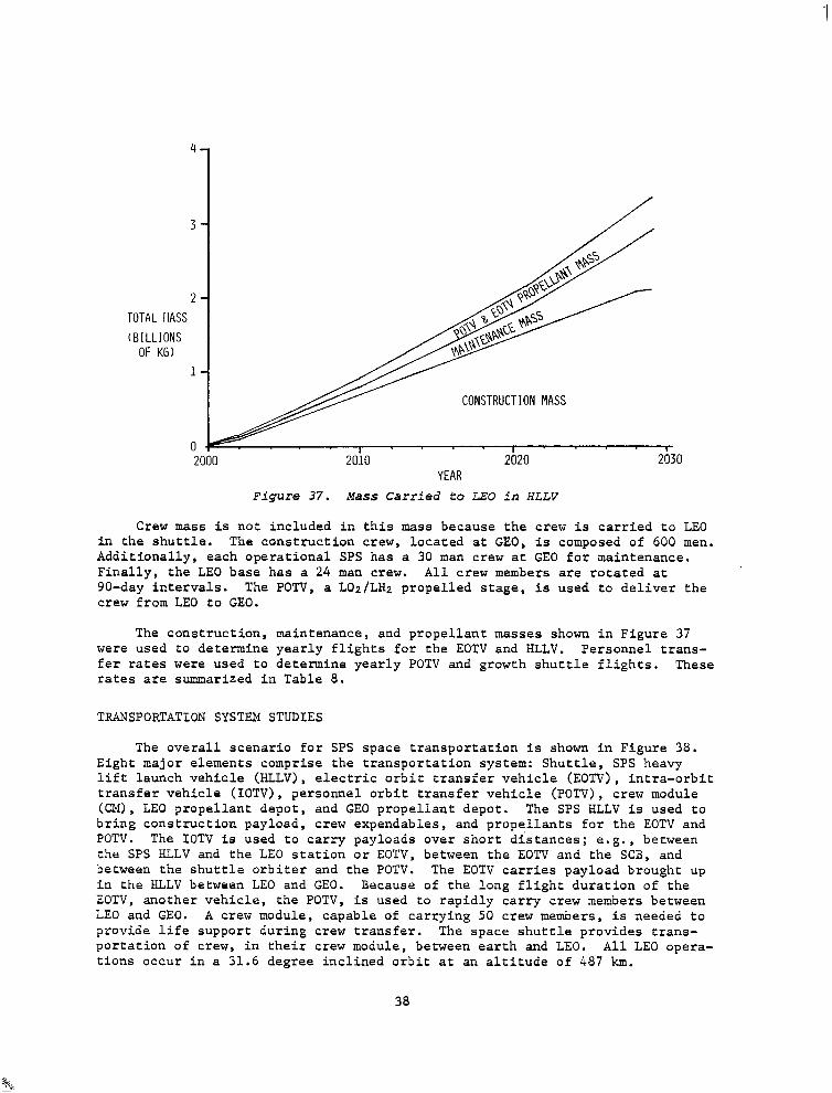
A detailed analysis of the mass flow was conducted and the results of this analysis are summarized in Figure 37, which shows the mass carried to LEO by the HLLV. This mass includes construction, maintenance and POTV and EOTV pro- pellants. It is assumed that 2 SPS's are constructed each year. As shown, the construction mass is the primary mass. Because of the high specific impulse of the EOTV, propellant masses are only 20% of the total mass.
37
4
1 3-
2- TOTAL IIASS (BILLIONS
OF KG) l-
CONSTRUCTION MASS
I 2000 2010 2020 2030
YEAR Figure 37. Mass Carried to LEO in HLLV
Crew mass is not included in this mass because the crew is carried to LEO in the shuttle. The construction crew, located at GEO, is composed of 600 men. Additionally, each operational SPS has a 30 man crew at GE0 for maintenance. Finally, the LEO base has a 24 man crew. All crew members are rotated at go-day intervals. The POTV, a LOz/LHz propelled stage, is used to deliver the crew from LEO to GEO.
The construction, maintenance, and propellant masses shown in Figure 37 were used to determine yearly flights for the EOTV and HLLV. Personnel trans- fer rates were used to determine yearly POTV and growth shuttle flights. These rates are summarized in Table 8.
TRANSPORTATION SYSTEM STUDIES
The overall scenario for SPS space transportation is shown in Figure 38. Eight major elements comprise the transportation system: Shuttle, SPS heavy lift launch vehicle (HLLV), electric orbit transfer vehicle (EOTV), intra-orbit transfer vehicle (IOTV), personnel orbit transfer vehicle (POTV), crew module (CM), LEO propellant depot, and GE0 propellant depot. The SPS HLLV is used to bring construction payload, crew expendables, and propellants for the EOTV and POTV. The IOTV is used to carry payloads over short distances; e.g., between the SPS HLLV and the LEO station or EOTV, between the EOTV and the SCB, and between the shuttle orbiter and the POTV. The EOTV carries payload brought up in the HLLV between LEO and GEO. Because of the long flight duration of the EOTV, another vehicle, the POTV, is used to rapidly carry crew members between LEO and GEO. A crew module, capable of carrying 50 crew members, is needed to provide life support during crew transfer. The space shuttle provides trans- portation of crew, in their crew module, between earth and LEO. All LEO opera- tions occur in a 31.6 degree inclined orbit at an altitude of 487 km.
38
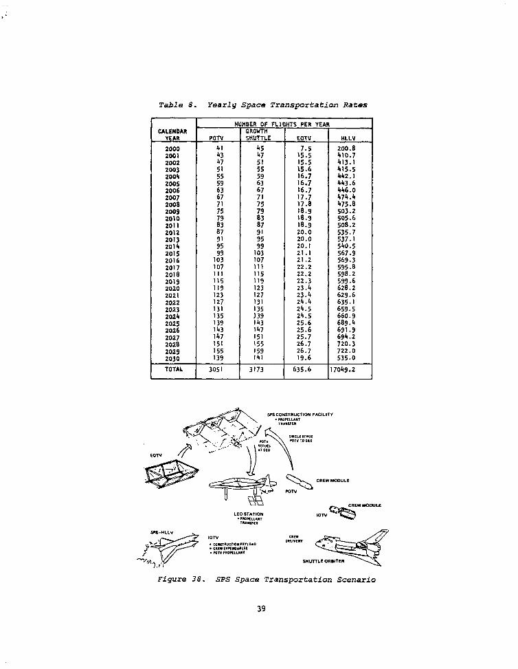
Table 8. Yearly Space Transportation Rates
CALENDAR YEAR
2000
2001 2002 2003 2004 2005 zoo6 2007 2008 2009
2010 2011 2012 2013 2014
2015 2016 2017 2018 2019 2020 2021 2022 2023 2024 2025 2026 2027 2028 2029 2030
TOTAL
NUHBER OF FLIGHTS PER YEAR GROUTH
POTU SHUTTLE EOTV HLLV
41 45 200.8
47
1;::
:: 15.5 :z ::
:: 15.6
2; 2; lb.7
p;::
16.7 44316 67 lb.7 446.0
;: 5: 17.7 17.8 :::*i ;; 79 18.9 503:2
2 18.9 18.9 ::i*; 87 91 20.0 z 2 20.0
g:;
20.1 540:5
103 21 .I 109; 107 21.2 :t;*; 107 111 22.2 595b 111 115 22.2 598.2 115 119 22.3 599.6 119 123 23.4 620.2 123 127 23.4 629.6 127 131 24.4 635.1 131 135 24.5 659.5 135 24.5 660.9 139
ii; 25.6 689.4
143 147 25.6 691.9 147 151 25.7 694.2 151 155 26.7 720.3 155 159 26.7 722.0 139 141 19.6 535.0
3051 3173 635.6 17049.2
Figure 38. SPS Space Transportation Scenario
39
The following sections describe the characteristics of the HLLV, EOTV, and POTV (including the crew module).
Heavy Lift Launch Vehicle
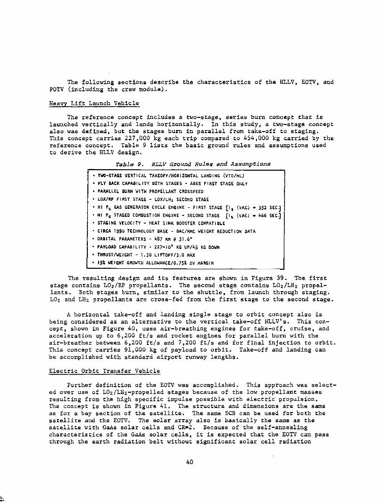
The reference concept includes a two-stage, series burn concept that is launched vertically and lands horizontally. In this study, a two-stage concept also was defined, but the stages burn in parallel from take-off to staging. This concept carries 227,000 kg each trip compared to 454,000 kg carried by the reference concept. Table 9 lists the basic ground rules and assumptions used to derive the HLLV design.
Table 9. HLLV Ground Rules and Assumptions r
. TWO-STAGE VERTICAL TAKEOFF/HORIZONTAL LANDING (VTO/HL)
l FLY BACK CAPABILITY BOTH STAGES - ABES FIRST STAGE ONLY
’ PARALLEL BURN WITH PROPELLANT CROSSFEED
* LOX/RP FIRST STAGE - LOX/LHI SECOND STAGE
l HI f’, GAS GENERATOR CYCLE ENGINE - FIRST STAGE [Is (VAC) = 352 SEC]
’ HI P, STAGED COHBUSTION ENGINE - SECOND STAGE [Is (vAC) I 466 SEC1
l STAGING VELOCITY - HEAT SINK BOOSTER COHPATIBLE
l CIRCA 1990 TECHNOLOGY BASE - BAC/HHC WEIGHT REDUCTION DATA
l ORBITAL PARAMETERS - 487 KH ? 31.6' l PAYLOAD CAPABILITY - 227x10’ KG UP/45 KG DOWN
l THRUST/WEIGHT - 1.30 LIFTOFF/3.0 tiAx
l 15% WEIGHT GROWTH ALLOWANCE/O.759 AV HARGIN
The resulting design and its features are shown in Figure 39. The first stage contains LOz/PP propellants. The second stage contains LOz/LHz propel- lants. Both stages burn, similar to the shuttle, from launch through staging. LO2 and LHz propellants are cross-fed from the first stage to the second stage.
A horizontal take-off and landing single stage to orbit concept also is being considered as an alternative to the vertical take-off HLLV's. This con- cept, shown in Figure 40, uses air-breathing engines for take-off, cruise, and acceleration up to 6,200 ft/s and rocket engines for parallel burn with the air-breather between 6,200 ft/s and 7,200 ft/s and for final injection to orbit. This concept carries 91,000 kg of payload to orbit. Take-off and landing can be accomplished with standard airport runway lengths.
Electric Orbit Transfer Vehicle
Further definition of the EOTV was accomplished. This approach was select- ed over use of LOz/LHz-propelled stages because of the low propellant masses resulting from the high specific impulse possible with electric propulsion. The concept is shown in Figure 41. The structure and dimensions are the same as for a bay section of the satellite. The same SCB can be used for both the satellite and the EOTV. The solar array also is basically the same as the satellite with GaAs solar cells and CR-2. Because of the self-annealing characteristics of the G&s solar cells, it is expected that the EOTV can pass through the earth radiation belt without significant solar cell radiation
40
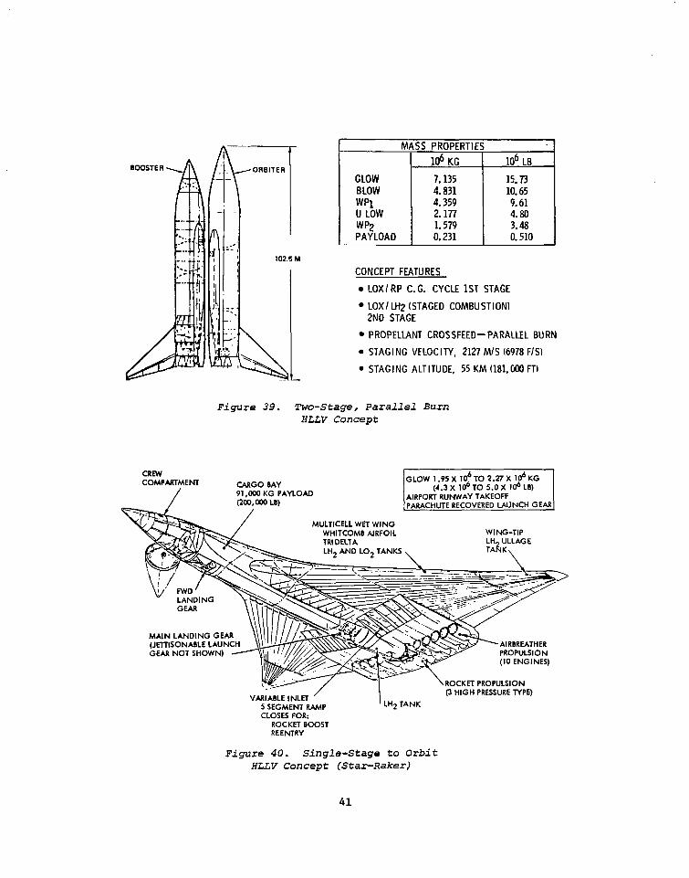
GLOW 7.135 15.73 BLOW 4.831 10.65 w 4.359 9.61 u LOW 2.177 4.80 WP2 1.579 3.48 PAYLOAD 0.231 0.510
CONCEPT FEATURES
. LOX/ RP C. G. CYCLE 1ST STAGE
l LOX/ LH2 (STAGED COMBUSTION1 2ND STAGE
l PROPELIANT CROSSFEED-PARALLEL BURN
. STAGING VELOCITY, 2127 MIS (6978 F/S)
l STAGING ALTITUDE, 55 KM f181,DOO FTI
Figure 39. Two-Stage, Parallel Burn HLLV Concept
CREW COMPMTMEM
/
CARGO BAY 91 ,UOO KG PAYLOAD (200,wo LB)
I
GEAR NOT SH AIRBREATHER PROPULSION (IO ENGINES)
ROCKET PROPULSION (3 HIGH PRESSURE TYPE)
5 SEGMENT RAMP CLOSES FOR:
ROCKET BOOST REENTRY
’ LH2 TANK
Figure 40. Single-Stage to Orbit IfLLV Concept (Star-Raker)
41
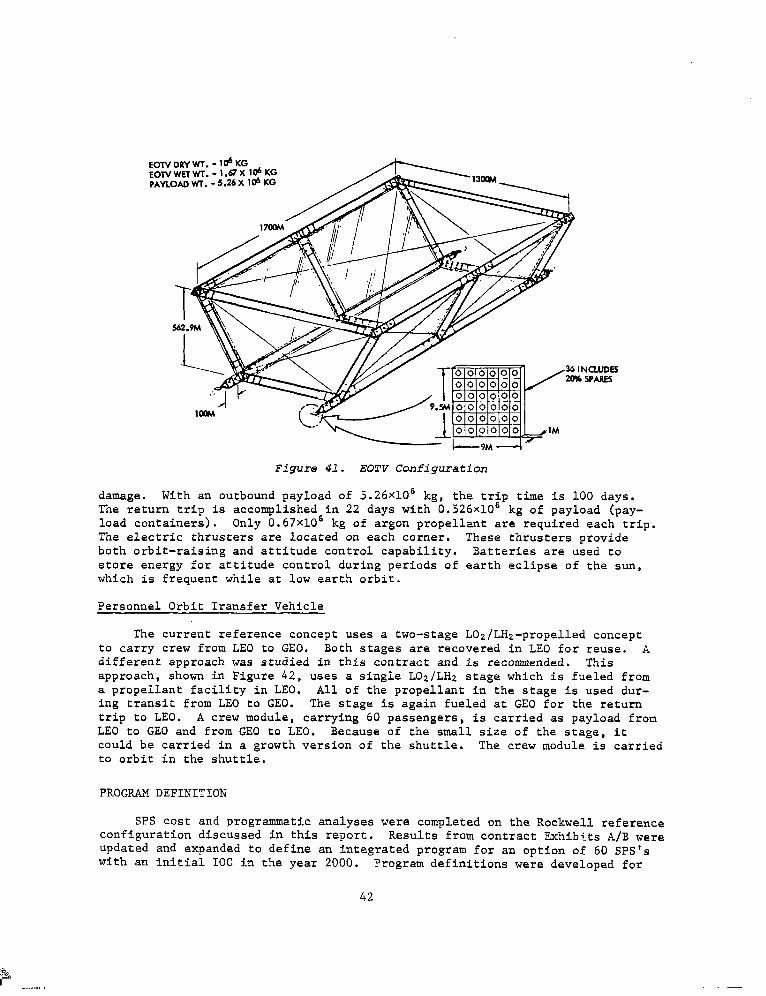
Figure 41. EOTV Configuration
damage. With an outbound payload of 5.26~10~ kg, the trip time is 100 days. The return trip is accomplished in 22 days with 0.526~10~ kg of payload (pay- load containers). Only 0.67~10~ kg of argon propellant are required each trip. The electric thrusters are located on each comer. These thrusters provide both orbit-raising and attitude control capability. Batteries are used to store energy for attitude control during periods of earth eclipse of the sun, which is frequent while at low earth orbit.
Personnel Orbit Transfer Vehicle
The current reference concept uses a two-stage LOz/LHz-propelled concept to carry crew from LEO to GEO. Both stages are recovered in LEO for reuse. A different approach was studied in this contract and is recommended. This approach, shown in Figure 42, uses a single LOz/LHz stage which is fueled from a propellant facility in LEO. All of the propellant in the stage Is used dur- ing transit from LEO to GEO. The stage is again fueled at GE0 for the return trip to LEO. A crew module, carrying 60 passengers, is carried as payload from LEO to GE0 and from GE0 to LEO. Because of the small size of the stage, it could be carried in a growth version of the shuttle. The crew module is carried to orbit in the shuttle.
PROGRAM DEFINITION
SPS cost and programmatic analyses were completed on the Rockwell reference configuration discussed in this report. Results from contract Exhibits A/B were updated and expanded to define an integrated program for an option of 60 SPS's with an initial IOC in the year 2000. Program definitions were developed for
42
ground-based exploratory research (1980-1985), program development and initial operations through year 2000, and the commercialization phase ending in year 2030.
A summary schedule that describes these phases is presented in Figure 42. It identifies the ground-based exploratory development activities and key tech- nology programs preceding the 1990 Phase C/D commercialization decision. The 335-MW EOTV precursor pilot plant is shown as an extension of the systems test activity. The 1990 Phase C/D activity will initiate work on all major elements leading to the SCB fabrication, EOTV test article assembly, transfer to GEO, and precursor testing/beam mapping. The growth Shuttle and Shuttle-derived cargo carrier will have an earlier start to transfer the necessary mass to orbit. Subsequent SPS HLLV operations will combine with the Shuttle for full- scale build-un of the first satellite.
Total program costs were developed for DDT&E, production, launch, orbital assembly/construction, ground operations, replacement capital, and operations/ maintenance in accordance with the SPS work breakdown structure. These elements are described in Figure 43 for main phases of the SPS program.
The DDT&E phase consists of the one-time effort associated with the design, development, and evaluation of comnonents, subsystems, and systems required for the SPS. DDT&E estimates cover SPS support systems such as space transportation, facilities, and the ground station. Total program development cost through the first SPS is $84.5 billion (DDT&E, 833.4 billion; TFLT, $51.1 billion). Satellite DDT&E is $7.9 billion and SPS space transportation DDT&E (including ground sup- port facilities) are estimated at $12.5 billion.
An analysis of TFU costs shows that the largest requirement is for space transportation and ground support facilities. This cost, $22.9 billion (44%), includes an estimate of the Initial transportation fleet (HLLV's and OTV's), facilities, and support systems that will have a lifetime capability of build- ing more than one SPS satellite. Space construction and support equipment also fall in this category and represent $8.6 billion of the TFLJ cost.
Investments per satellite are the cost estimates of an average unit of the total 60-unit program. This average cost of $13.9 billion includes $5.3 billion for the satellite, $3.6 billion for the ground receiving station, and $1.9 billion for space transportation/ground support facilities. The aver- age investment cost per SPS is $3OlO/kW.
SPS replacement cost and operations/maintenance estimates have been com- bined into a single figure with an annual cost of $0.2 billion per satellite.
As a secondary objective, nlanning areas requiring substantial effort during the Phase C/D activity were identified for the various SPS elements. This work concluded in a series of main SPS program plans listed in Table 10. Program schedules and networks, technology/system requirements, and resource considerations are principal items addressed in these program plans. In addi- tion, an analysis of natural resources identified material requirements for the first satellite and ground receiving station requirements needed for the transportation system.
43
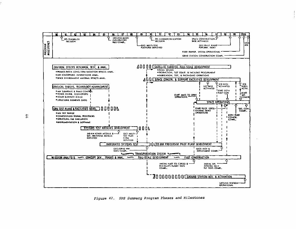
ENVIRON. EFFEClS RCSEARCH, TEST. L ANAL.
jCRlTlCA1 SUBSYS. 1ECHNOlOGYAOVANCEMENT
A @ SPACE CONSTR. b SUPPORT fAClllllES DEVELOPMENT
I
No-KW fOWfR MOD.ILf ‘ IAl. IICIINNA MOWLL DtrLOYtD
I 1 I I
; I;;
0 1335 MW PRECURSOR PILOT PLAN: DEVELOPMENT .
I
- TRANS~QIATION SYSTEM - I
1 MISSION ANALYSIS - CONCEPT DEV.. TRADES L ANAL - 1 I
FULL-SCALE DEVELOPMENT - FWI CONSTRUCTION 1 I 4 4
-30 00 0 fl [I 0 0 n 1 GROUND STATION DIV. 6 ACTIVATION
UOUND VA110 OMUIIOWL
Figure 42. SPS Summary Program Phases and Milestones
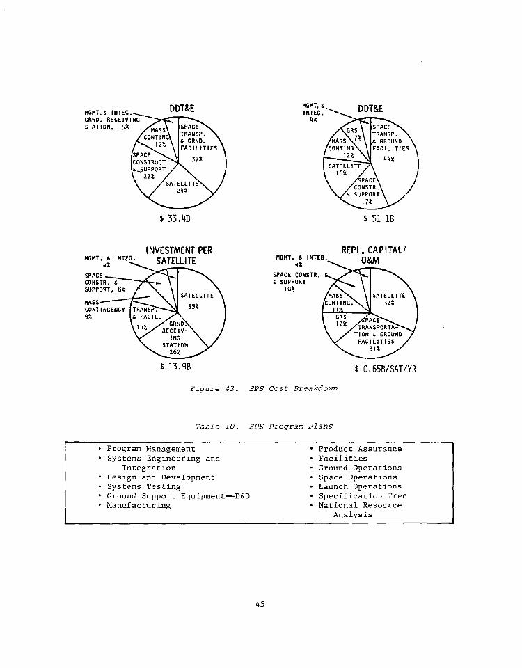
$ 33.4B b 51,lB
INVESTMENT PER
\ 1 SATELLITE \
REPL. CP MGHT. C INTEG.
---. - -,PITALI
/CANTING.\ \I
$ 13,9B
Figure 43. SPS Cost Breakdown
Table 10. SPS Program Plans
d 0,65B/SAT/YR
l Program Management l Systems Engineering and
Integration l Design and Development l Systems Testing l Ground Support Equipment-D&D . Manufacturing
l Product Assurance l Facilities . Ground Operations l Space Operations l Launch Operations . Specification Tree . National Resource
Analysis
45

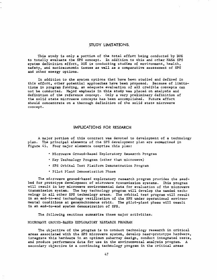
STUDY LIMITATIONS.
This study is only a portion of the total effort being conducted by DOE to totally evaluate the SPS concept. In addition to this and other NASA SPS system definition effort, DOE is conducting studies of environment, health, safety, and socioeconomic issues as well as a comparative assessment of SPS and other energy options.
In addition to the system options that have been studied and defined in this effort, other potential approaches have been proposed. Because of limita- tions in program funding, an adequate evaluation of all credible concepts can not be conducted. Major emphasis in this study was placed on analysis and definition of the reference concept. Only a very preliminary definition of the solid state microwave concepts has been accomplished. Future effort should concentrate on a thorough definition of the solid state microwave concept.
IMPLICATIONS FOR RESEARCH
A major portion of this contract was devoted to development of a technology plan. The principal elements of the SPS development plan are summarized in Figure 45. Four major elements comprise this plan:
l Microwave Ground-Based Exploratory Research Program
l Key Technology Program (other than microwave)
l SPS Orbital Test Platform Demonstration Program
l Pilot Plant Demonstration Phase
The microwave ground-based exploratory research program provides the seed- bed for prototype development of microwave transmission systems. This program will result in key microwave environmental data for evaluation of the microwave transmission system. The key technology program will develop the needed tech- nology in all other SPS technology areas. The orbital test program will result in an end-to-end technology verification of the SPS under operational environ- mental conditions at geosynchronous orbit. The pilot-plant phase will result in an end-to-end system demonstration of SPS.
The following sections summarize these major activities.
MICROWAVE GROUND-BASED EXPLORATORY RESEARCH PROGRAM
The objective of the program is to conduct technology research in critical areas associated with the SPS microwave system, develop near-prototype hardware, integrate this hardware in an optimum subarray design, conduct integrated tests, and produce performance data for use in the environmental analysis program. A secondary objective is a continuing technology program in the critical areas
47
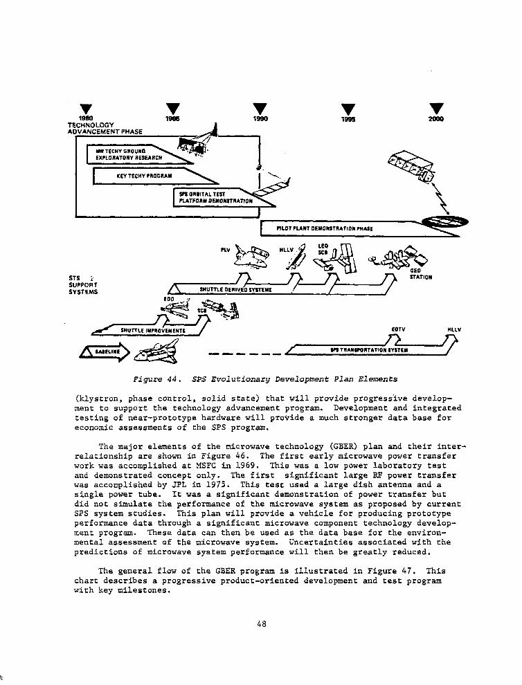
v 1995 1980
TECHNOLOGY AOVANCEMENT PHASE
EX?LORATORY RESEARCH
FILOT PLANT DEYONSTRAJIOI PHASE
STS S”PPO6T SYSTEMS
SWl-TLE IYPIOVEMENTL EOTV WLV
US TllAllS?011TATIO# SYSTEM ------
Figure 44. SPS Evolutionary Development Plan Elements
(klystron, phase control, solid state) that will provide progress'ive develop- ment to support the technology advancement program. Development and integrated testing of near-prototype hardware will provide a much stronger data base for economic assessments of the SPS program.
The major elements of the microwave technology (GBER) plan and their inter- relationship are shown in Figure 46. The first early microwave power transfer work was accomplished at MSFC in 1969. This was a low power laboratory test and demonstrated concept only. The first significant large RF power transfer was accomplished by JPL in 1975. This test used a large dish antenna and a single power tube. It was a significant demonstration of power transfer but did not simulate the performance of the microwave system as proposed by current SPS system studies. This plan will provide a vehicle for producing prototype performance data through a significant microwave component technology develop- ment program. These data can then be used as the data base for the environ- mental assessment of the microwave system. Uncertainties associated with the predictions of microwave system performance will then be greatly reduced.
The general flow of the GBER program is illustrated in Figure 47. This chart describes a progressive product-oriented development and test program with key milestones.
48
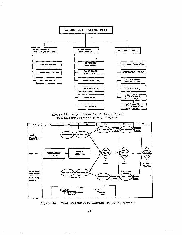
EXPLORATORY RESEARCH PLAN
I I TEST SUCCOR1 L COMMNENT FACILITY WERATIONS DEVELOPMENT
INTEGRATED TESTS
FACILITY MOOS KLYSTRON AMPLIFIER INTEGRATED TESTING
INSTRUMENTATION SOLID STATE AMPLIFIER
COMPONENT TESTING
,----------------------. I,: TEST FROGRAM :
i : MASE CONTRdL
TEST/FACILITIES RLnUlnLMfN1.s ..-...-......--.---..-J
-
RF RADIATOR I
Figure 45. Major Elements of Ground Based Exploratory Research (GBER) Program
Figure 46. GBER Program Flow Diagram Technical Approach
49
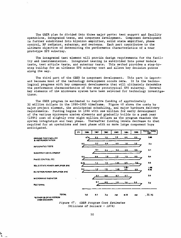
The GBER plan is divided into three major parts: test support and facility operations, integrated tests, and component development. Component development is further subdivided into klystron amplifier, solid state amplifier, phase control, RF radiator, subarray, and rectenna. Each part contributes to the ultimate objective of determining the performance characteristics of a near prototype SPS subarray.
The integrated test element will provide design requirements for the facil- ity and instrumentation. Integrated testing is subdivided into power module tests, test article tests, and subarray tests. This method provides a step-by- step buildup for an ultimate SPS subarray test and allows key decision points along the way.
The third part of the GBER is component development. This part is import- ant because most of the technology development occurs here. It is the techno- logical progress with key component developments that will ultimately determine the performance characteristics of the near prototypical SPS subarray. Several key elements of the microwave system have been selected for technology investiga- tions.
The GBER program is estimated to require funding of approximately 32 million dollars in the 1980-1985 timeframe. Figure 48 shows the costs by major project element, the anticipated scheduling, and major hardware delivery requirements. Funding begins in 1980 with one million for early development of the various microwave system elements and gradually builds to a peak year (1984) cost of slightly over eight million dollars as the program reaches the system integration and test phase. Thereafter funding levels decrease to that required for an operations and test phase with no more large component buys an&cipated.
GROUNO TEST FACILITY L INSTRUMENTATION
INTEGRATED TESTS
SUBARRAY DEVELOPMENT
PMASE CONTROL IPCI
90LIfJ STATE COWER AMPLIFIER IPA)
KLYSTRON POWER AMRIFlER lPAI
MICROWAVE RADIATOR
RECTENN*
TOTAL
*EITHER g OK KLVSfRON (15S4 DECISION)
Oh 0.3 1.5 1 .o 0.5 0.5 Is5
02 02 0.5 0.5 1.0 1.0 3.3
0.1 04 0.4 06 0.6 2.1
/
0.2 0.9 1.0 1.3 1.5 0.5 k4
0.25 1.2 1.5 1.45 0.5 0.5 1.6
1.s. 0.2
1.m 12 1.5 I.45 0.5 0.5 s.4s
0.1 0.5 0.7 0.7 2.0
/
0.1 0.5 1 .o 1.0 0.4 3.a
------
1.0 4.1 7.4 73 8.16 4) ,32.4s
Figure 47. GBER Program Cost Estimates (Millions of Dollars - 1978)
50
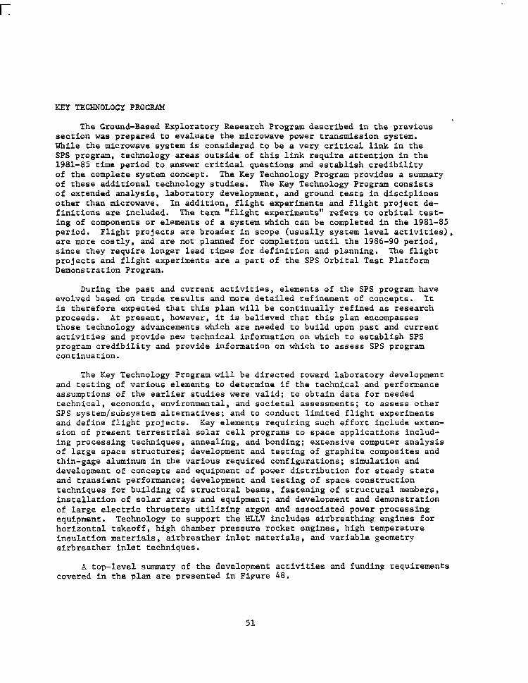
KEY TECHNOLOGY PROGRAM .
The Ground-Based Exploratory Research Program described in the previous section was prepared to evaluate the microwave power transmission system. While the microwave system is considered to be a very critical link in the SPS program, technology areas outside of this link require attention in the 1981-85 time period to answer critical questions and establish credibility of the complete system concept. The Key Technology Program provides a summary of these additional technology studies. The Key Technology Program consists of extended analysis, laboratory development, and ground tests in disciplines other than microwave. In addition, flight experiments and flight project de- finitions are included. The term "flight experiments" refers to orbital test- ing of components or elements of a system which can be completed in the 1981-85 period. Flight projects are broader in scope (usually system level activities), are more costly, and are not planned for completion until the 1986-90 period, since they require longer lead times for definition and planning. The flight projects and flight experiments are a part of the SPS Orbital Test Platform Demonstration Program.
During the past and current activities, elements of the SPS program have evolved based on trade results and more detailed refinement of concepts. It is therefore expected that this plan will be continually refined as research proceeds. At present, however, it is believed that this plan encompasses those technology advancements which are needed to build upon past and current activities and provide new technical information on which to establish SPS program credibility and provide information on which to assess SPS program continuation.
The Key Technology Program will be directed toward laboratory development and testing of various elements to determine if the technical and performance assumptions of the earlier studies were valid; to obtain data for needed technical, economic, environmental, and societal assessments; to assess other SPS system/subsystem alternatives; and to conduct limited flight experiments and define flight projects. Key elements requiring such effort include exten- sion of present terrestrial solar cell programs to space applications includ- ing processing techniques, annealing, and bonding; extensive computer analysis of large space structures; development and testing of graphite composites and thin-gage aluminum in the various required configurations; simulation and development of concepts and equipment of power distribution for steady state and transient performance; development and testing of space construction techniques for building of structural beams, fastening of structural members, installation of solar arrays and equipment; and development and demonstration of large electric thrusters utilizing argon and associated power processing equipment. Technology to support the HLLV includes airbreathing engines for horizontal takeoff, high chamber pressure rocket engines, high temperature insulation materials, airbreather inlet materials, and variable geometry airbreather inlet techniques.
A top-level summary of the development activities and funding requirements covered in the plan are presented in Fipure 48.
51
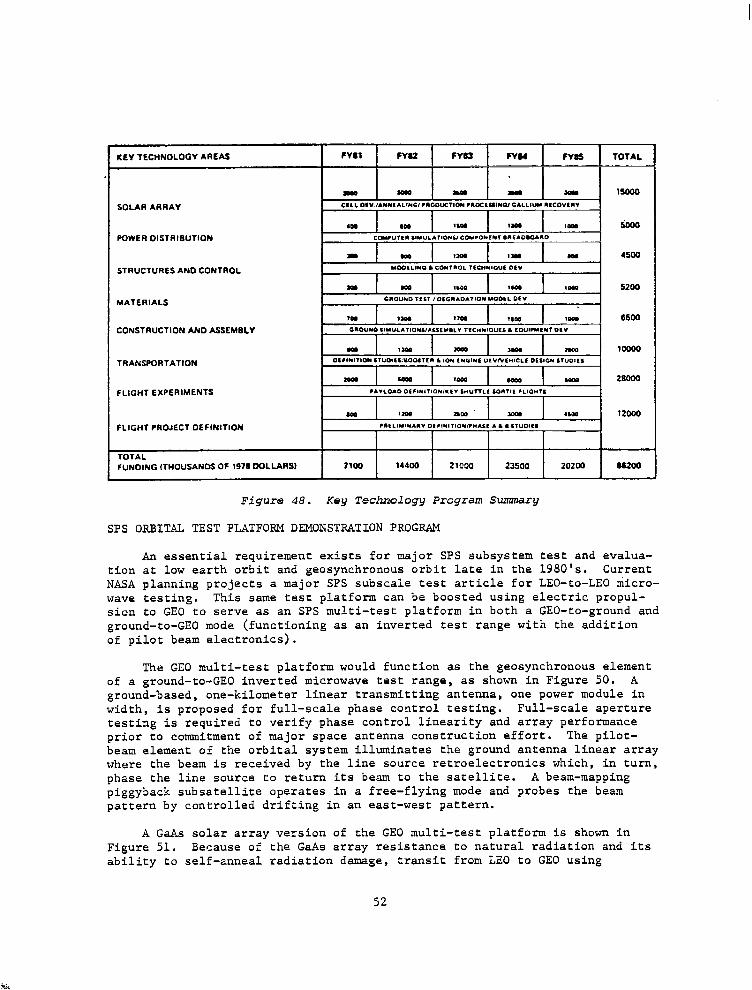
SOLAR ARRAY
POWER OlSTRlSUTlON
STRUCTURES AND CONTROL
MATERIALS
CONSTRUCTION AN0 ASSEMBLY
TRAN!PORTATlON
FLIGHT EXPERIMENTS
TOTAL FUNDING W4OUSANOS OF 1978 WLURS)
Figure 48. Key Technology Program Summary
SPS ORBITAL TEST PLATFORM DEMONSTRATION PROGRAM
An essential requirement exists for major SPS subsystem test and evalua- tion at low earth orbit and geosynchronous orbit late in the 1980's. Current NASA planning projects a major SPS subscale test article for LEO-to-LEO micro- wave testing. This same test platform can be boosted using electric propul- sion to GE0 to serve as an SPS multi-test platform in both a GEO-to-ground and ground-to-GE0 mode (functioning as an inverted test range with the addition of pilot beam electronics).
The GE0 multi-test platform would function as the geosynchronous element of a ground-to-GE0 inverted microwave test range, as shown in Figure 50. A ground-based, one-kilometer linear transmitting antenna, one power module in width, is proposed for full-scale phase control testing. Full-scale aperture testing is required to verify phase control linearity and array performance prior to commitment of major space antenna construction effort. The pilot- beam element of the orbital system illuminates the ground antenna linear array where the beam is received by the line source retroelectronics which, in turn, phase the line source to return its beam to the satellite. A beam-mapping piggyback subsatellite operates in a free-flying mode and probes the beam pattern by controlled drifting in an east-west pattern.
A GaAs solar array version of the GE0 multi-test platform is shown in Figure 51. Because of the GaAs array resistance to natural radiation and its ability to self-anneal radiation damage, transit from LEO to GE0 using
52
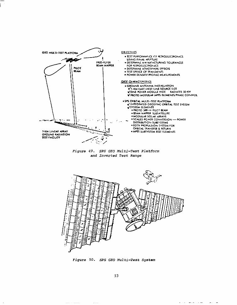
GE0 MULTI-TEST PLATFORM
FREE-FLYER 8UM MUPER
I-IW LINEAR MRAY .,.
OIJICllVCs
. NY.1 P~RFCPM~~IC~ C.F RCTRO~LZCTRO~~ICS USING FINAL APLETIJRE
. OCTtRMlhrC MA~~JFACTURING TOLCRANCES FOR RET~O~LLCTRO~~ICS
l DE ItPMlNE ATMOSPMPL EFFECTS . TEST EFFECT OF TRAb.SITNTS l POWER DLNSITY PROFILL MLASUREMENTS
CRTf CH*RACTF*I~TICS
. GROUND ANTLNNA INSTALLATION dl-UM EAST-WEST LINE SCURCE SIZE *IONE POWER MODULE WIOE RADIATES SO KW *‘PKOTO MOOU<M MPTS ELEMENTS/PliA5,E CONTROL
l SPS ORsllu MULTI-TEST PLATFORM ~INTEGRATEO GEOSYNC ORBITAL TEST SYSTEM *ISYSTEM ELEMENTS
*PROTO wx)-w PILOT OEM4 . SEAM .MAPPER SUaSATELLITE
R ARRAYS CONVERSION -POWER
TEST FACILITY
l MODULAR SOLA _ . SCALED PCWER I
Figure 49. SPS GE0 Multi-Test Platform and Inverted Test Range
Figure 50. SPS GE0 Multi-Test System
53
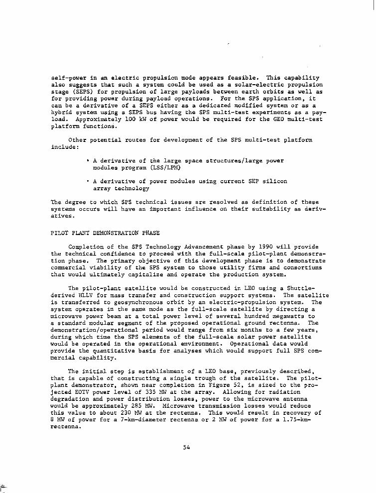
self-power in an electric propulsion mode appears feasible. This capability also suggests that such a system could be used as a solar-electric propulsion stage (SEPS) for propulsion of large payloads between earth orbits as well as for providing power during payload operations. For the SPS application, it can be a derivative of a SEPS either as a dedicated modified system or as a hybrid system using a SEPS bus having the SPS multi-test experiments as a pay- load. Approximately 100 kW of power would be required for the GE0 multi-test platform functions.
Other potential routes for development of the SPS multi-test platform include:
l A derivative of the large space structures/large power modules program (LSS/LPM)
l A derivative of power modules using current SEP silicon array technology
The degree to which SPS technical issues are resolved as definition of these systems occurs will have an important influence on their suitability as deriv- atives.
PILOT PLANT DEMONSTRATION PHASE
Completion of the SPS Technology Advancement phase by 1990 will provide the technical confidence to proceed with the full-scale pilot-plant demonstra- tion phase. The primary objective of this development phase is to demonstrate commercial viability of the SPS system to those utility firms and consortiums that would ultimately capitalize and operate the production system.
The pilot-plant satellite would be constructed in LEO using a Shuttle- derived HLLV for mass transfer and construction support systems. The satellite is transferred to geosynchronous orbit by an electric-propulsion system. The system operates in the same mode as the full-scale satellite by directing a microwave power beam at a total power level of several hundred megawatts to a standard modular segment of the proposed operational ground rectenna. The demonstration/operational period would range from six months to a few years, during which time the SPS elements of the full-scale solar power satellite would be operated in the operational environment. Operational data would provide the quantitative basis for analyses which would support full SPS com- mercial capability.
The initial step is establishment of a LEO base, previously described, that is capable of constructing a single trough of the satellite. The pilot- plant demonstrator, shown near completion in Figure 52, is sized to the pro- jected EOTV power level of 335 MW at the array. Allowing for radiation degradation and power distribution losses, power to the microwave antenna would be approximately 285 MW. Microwave transmission losses would reduce this value to about 230 MW at the rectenna. This would result in recovery of 8 MW of power for a 7-km-diameter rectenna or 2 MW of power for a 1.75-km- rectenna.
54
Figure 51. SPS Pilot Plant in Final Phases of Construction
55

r
SUGGESTED ADDITIONAL EFFORT
As a result of this study, major areas of future emphasis have been identified for system studies and for near-term technology development.
SYSTEM STUDIES
This study has resulted in an identification of potentially attractive solid-state microwave transmission concepts. Effort in this contract has not yet been sufficient to define these concepts adequately to determine the best approaches and to evaluate them relative to the current reference concept. It is recommended that this effort be continued and heavily emphasized in follow-on system studies.
This contract has resulted in an adequate definition of the electric orbit transfer vehicle and the personnel orbit transfer vehicle. However, transpor- tation costs are most sensitive to the heavy lift launch vehicle operational and fleet costs. Two approaches have been identified for the HLLV; a parallel- burn, two-stage, vertical take-off and horizontal landing concept and a hori- zontal take-off and landing single-stage to orbit concept. Further definition of these concepts is needed to support launch cost estimates.
The rectenna system installation approach has been defined in this study, but two issues still need to be resolved: lightning protection requirements and their resulting design implications and design analysis and impacts for high wind conditions. These issues can have a significant impact on rectenna installation costs.
TECHNOLOGY DEVELOPMENT
Three primary areas, in addition to the on-going NASA large structures technology development, have been identified for immediate technology develop- ment:
l Advanced GaAs solar cell development
l Solid-state device and microwave system development
l Dc-dc converter and switchgear technology
A detailed plan for advanced GaAs solar cell development has been prepared and is contained in Reference 3. This proposed effort includes development and testing of prototype GaAs solar cells with a sapphire substrate, preliminary development of peeled-film technology solar cells, definition of manufacturing methods, and prediction of production rate capability. Testing includes radia- tion environment effects and solar cell performance measurements.
57
In order to bring solid state microwave technology to a position competi- tive with klystron technology, early device (transistor) and power amplifier research is needed. It is recommended that work be immediately initiated on advanced GaAs transistor development and that amplifier circuits be developed using available GaAs transistors. The circuit research will provide a current technology base for amplifier performance and will demonstrate electronic com- bining of microwave circuits.
No NASA or DOE plan has been identified for early development of high power and voltage dc/dc converters and switchgear that will be needed about 1987 for space technology verification. Although such equipment is in use for ground systems, technology development is needed to improve efficiency at much lower mass.
NASA currently has a program for development of large structures. Current effort appears to be generic and does not have sufficient application to SPS. It is recommended that the program be refocused to provide at least the minimum effort required to support SPS structure definition, evaluation, and ground test, and technology verification effort in the 1985-1990 time period.
58
REFERENCES
1. Satellite Power System (SPS) Concept Definition Study Final Report, Contract NAS8-32475 (Exhibits A and B), SD 78-AP-0023-l to -7, April 1978
2. Solar Power Satellite Concept Development and Evaluation Program, Reference System Report, United Stated Department of Energy and the NASA, October 1978
3. Proposal for an Advanced GaAs Solar Cell Development for Satellite Power Systems (SPS), SD 78-AP-0129, Rockwell International Satellite Systems Division, October 9, 1978
59
1. Report No. 2. Government Accarion No. 3. Recipient’s Catalog No.
NASA CR-3317 4. Title and Subtitle 5. Report Date
September 1980 SATELLITE POWER SYSTEMS (SPS) CONCEPT DEFINITION STUDY VOLUME I - EXECUTIVE SUMMARY 6. Pet-forming Orgenization Code
7. Author(r) 6. Performing Oqnization Report No.
G. M. Hanley SSD 79-0010-l 10. Work Unit No.
9. Performing Organization Name and Address
Rockwell International 11. Contract or Grant No.
12214 Lo kewood Boulevard
Downey, CA 90241 NAS8-32475
13. Type of Report and Period Covered
12. Sponsormg Agency Name and Address Contractor Report National Aeronautics and Space Administration
Washington, D. C. 203% 14. Sponsoring Agency Code
15. Supplementary NOES
Marshall Technical Monitor: C. H. Guttman Volume I of Final Report
16. Abstract
This report summarizes Satellite Power System (SPS) concept definition studies (Exhibit C) conducted for the NASA Marshall Space Flight Center. !lajor areas included system definition, special emphasis studies, transportation system studies,and program definition. System Definition studies resulted in a furtherdefinition of the "Reference" system using gallium arsenide solar arrays, analysis of alternative subsystem options for the reference concept, preliminary solid-state microwave concept studies, and an environmental analysis of laser transmission systems. The special emphasis studies concentrated on satellite construction, satellite construction base definition, satellite construction base construction, and rectenna construction. Major emphasisin the transpor- tation studies was put on definition of a two-stage parallel-burn, vertical take-off/horizontal landing concept capable of carrying 230,000 kg of payload. The electric orbit transfer vehicle was defined in greater Setail. Program definition included cost analyses and schedule definition.
7. Key Words lSug9ested by Author(s)) 18. Distribution Statement
jystem Definition Laser Transmissicn Unclassified - Unlimited GPS Microwave Transmission snergy Systems Cost Data solar Photovoltaic Program Definition
Subject Category 44 9. Security Classif. (of this report1 20. Security Clruif. (of this pqe.1 21. No. of Pages 22. Rice
Unclassified Unclassified 69 A04
For sale by the Nallonal TechnIcal InformatIon Service. Sprqfleld. Vlrglrua 22161 NASA-Lang1 ey, 1980