Embed Size (px)
Citation preview
WIRELESSENGINEERThe Journal of Radio Research & Progress
Vol. XXIII. NOVEMBER 1946
CONTENTSEDITORIAL Permeability of Iron -
Dust Cores . . . . . . 291DOUBLE -DERIVED TERMINATIONS
By R. 0. Rowlands, B.Sc. . . . 292CHARACTERISTICS OF R.F. CABLES
By N. C. Stamford, M.Sc., Tech.,and R. B. Quarmby, M.Sc. . . .. 295
NEGATIVE RESISTANCE CIRCUITELEMENTBy G. A. Hay, M.Sc. . . 299
TRANSIENT RESPONSE OF FILTERSBy C. C. Eaglesfield .. .. . . 306
BOLOMETERS FOR V.H.F. POWERMEASUREMENTBy E. M. Hickin . . 308
CORRESPONDENCE .. 313WIRELESS PATENTS .. . . 316ABSTRACTS AND REFERENCES
Nos. 3157-3508 A.231 -A.254
Published on the sixth of each monthSUBSCRIPTIONS (Home and Abroad)
One Year 32/- 6 months 16/ -Telephone: Telegrams:
WATerloo 3333 (35 lines) Wirenger Sedist London
No. 278
.JIFFE & SONS LTD. DORSET HOUSE STAMFORD ST. LONDON S.E.1
WIRELESSENGINEER
November, 1946
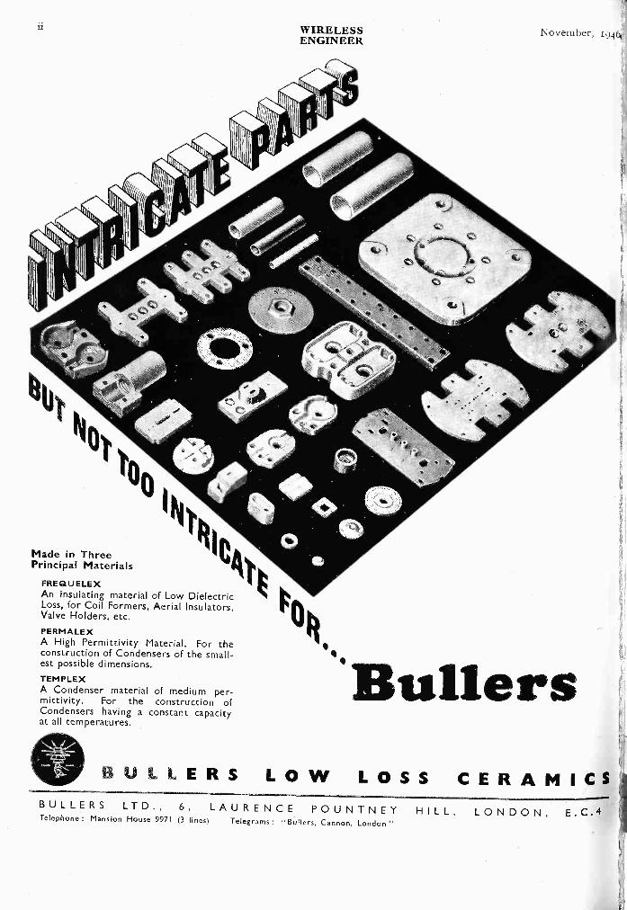
Made in ThreePrincipal Materials
FREQUELEXAn insulating material of Low DielectricLoss, for Coil Formers, Aerial Insulators,Valve Holders, etc.PERMALEXA High Permittivity Material. For theconstruction of Condensers of the small-est possible dimensions.
TEMPLEXA Condenser material of medium per-mittivity. For the construction ofCondensers having a constant capacityat all temperatures.
'BullersBULLERS LOW LOSS CERAMICS
BULLERS LTD., 6, LAURENCE POUNTNEY HILL, LONDON, E.C.4Telephone : Mansion House 9971 (3 lines) Telegrams : -Bullers, Cannon, London "
November, 1946WIRELESSENGINEER
LIB
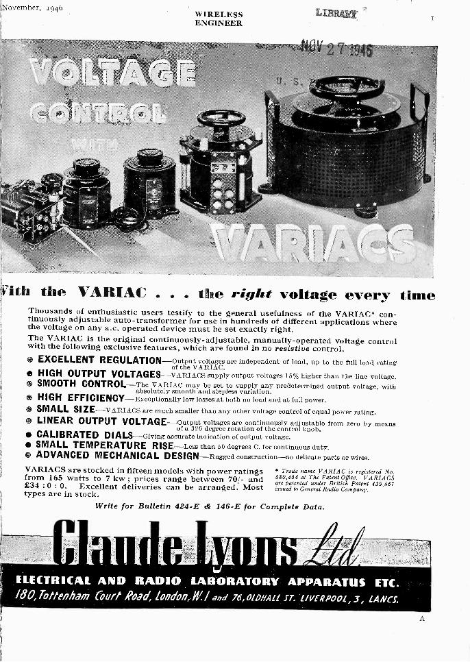
Vith the VARIAC . . . the right voltage every timeThousands of enthusiastic users testify to the general usefulness of the VARIAC* con-tinuously adjustable auto -transformer for use in hundreds of different applications wherethe voltage on any a.c. operated device must be set exactly right.The VARIAC is the original continuously -adjustable, manually-operated voltage controlwith the following exclusive features, which are found in no resistive control. EXCELLENT REGULATION-outputvoltages are independent of load, up to the full load, rating
of the VARIAC. HIGH OUTPUT VOLTAGES-VARIACS supply output voltages 15% higher than the line voltage. SMOOTH CONTROL-The VA MAC may be set to supply any predetermined output voltage, with
absolutely smooth and stepless variation. HIGH EFFICIENCY-Exceptionally low losses at both no load and at full power. SMALL SI ZE-VARIACS are much smaller than any other voltage control of equal power rating. LINEAR OUTPUT VOLTAGE-output voltages are continuously adjustable from zero by means
of a 320 degree rotation of the control knob. CALIBRATED DIALS-Giving accurate indication of output voltage. SMALL TEMPERATURE RISE-Less than 50 degrees C. for continuous duty. ADVANCED MECHANICAL DESIGN-Rugged construction-no delicate parts or wires.
VARIACS are stocked in fifteen models with power ratingsfrom 165 watts to 7 kw ; prices range between 70/- and£34 :0 : 0. Excellent deliveries can be arranged. Mosttypes are in stock.
Write for Bulletin 424-E & 146-E for Complete Data.
I I it I ILi
ELECTRICAL AND RADIO LABORATORY APPARATUS ETC.180, Tottenham (Mit /PAM; London, if / and 76,01DHALL ST. L/VERPOOL, 3, LANCS.
* Trade name VARIAC is registered No.580,454 at The Patent Office. VARIACSare patented under British Patent 439,667issued to General Radio Company.
A
WIRELESSENGINEER
November, 194C
from f
Ae ottsv
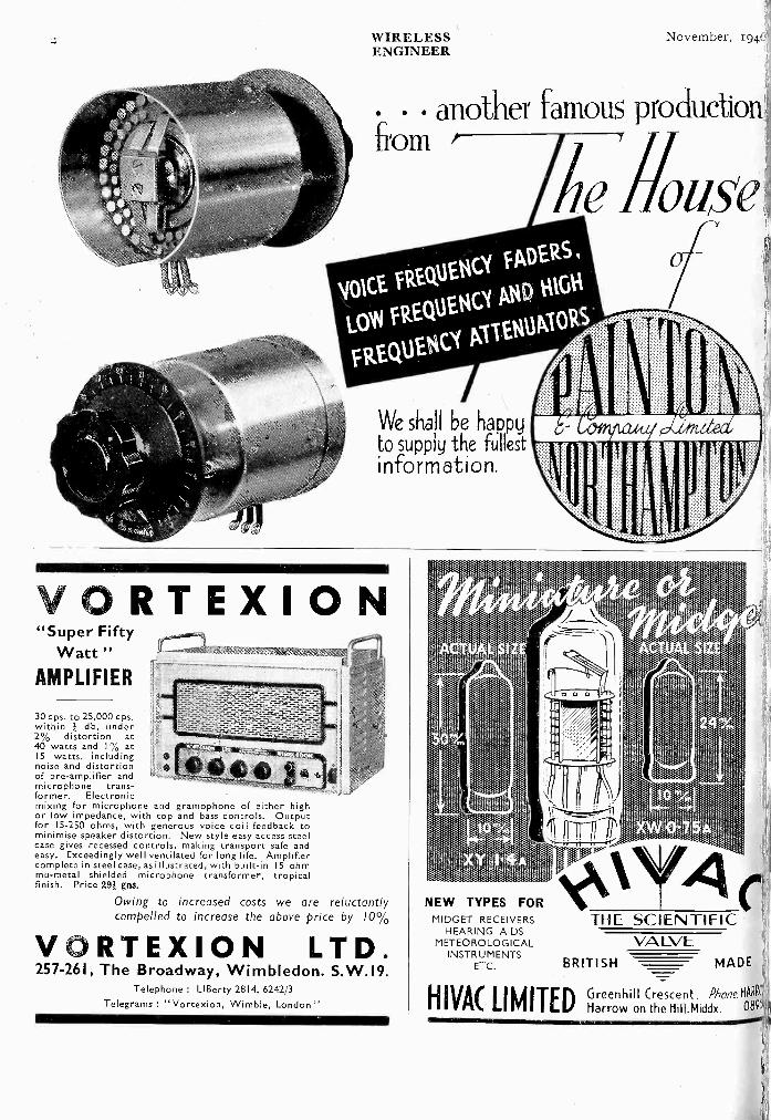
VORTEXION"Super Fifty
Watt "AMPLIFIER
30 cps. to 25,000 cps.within db, under2% distortion at40 watts and I% at15 watts, includingnoise and distortionof pre -amplifier andmicrophone trans-former. Electronicmixing for microphone and gramophone of either highor low impedance, with top and bass controls. Outputfor 15-250 ohms, with generous voice coil feedback tominimise speaker distortion. New style easy access steelcase gives recessed controls, making transport safe andeasy. Exceedingly well ventilated for long life. Amplifiercomplete in steel case, as illustrated, with built-in 15 ohmmu -metal shielded microphone transformer, tropicalfinish. Price 29+ gns.
Owing to increased costs we are reluctantlycompelled to increase the above price by 10%
VORTEXION LTD.257-261, The Broadway, Wimbledon. S.W.I9.
Telephone : LIBerty 2814, 6242/3
Telegrams: " Vortexion, Wimble, London"
NEW TYPES FORMIDGET RECEIVERS
HEARING AIDSMETEOROLOGICAL VALVE
INSTRUMENTSETC. BRITISH MADE
HIVAC LIMITED Greenhill Crescent, Phone H089
Harrow on the Hill.Middx. 8951
THE SCIENTIFIC
another famous production
li
November, 1946 WIRELESSENGINEER 3
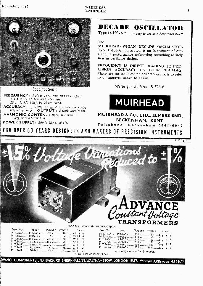
Specification :
FREQUENCY : 1 cls to 111.1 kc/s on two ranges:1 c/s to 11.11 kcls by 1 c!s steps.10 c/s to 111.1 ice's by 10 c/s steps.
ACCURACY : ± 0.2% or = 2 cls over the entirefrequency range. OUTPUT : 2 watts maximum.
HARMONIC CONTENT : 2i% at 2 watts:1.25% or less below 1 watt.
POWER SUPPLY : 200 to 250 v. 50 c/s.
DECADE OSCILLATORType D -105-A "... as easy to use as a Resistance Box "
TheMUIRHEAD - WIGAN DECADE OSCILLATOR.Type D -105-A, illustrated, is an instrument of out-standing performance embodying something entirelynew in oscillator design.
FREQUENCY IS DIRECT READING TO PRE-CISION ACCURACY ON FOUR DECADES.There are no troublesome calibration charts to referto or engraved scales to adjust.
Write for Bulletin, B -S28 -B.
MUIRHEADMUIRHEAD & CO. LTD., ELMERS END,
BECKENHAM, KENTTelephone: Beckenham 0041-0042
FOR OVER 60 YEARS DESIGNERS AND MAKERS OF PRECISION INSTRUMENTS
MODELS NOWType No.: Input : Output : Watts : Price :M.T. I89A 190/260 v 230 v 10 £3 15 0M.T.I 89E 190/260 v 6 v 4 £3 15 0M.T.161A 190/260 v 230 v 60 a 11 3M.T.161C 95/130 v 110 v 60 £7 I 1 3M.T.161D 95/130 v 230k 60 £7 II 3M.T.161E 190/260 v 6 v 36 £7 I 1 3M T 16IF 190/260 v 12 v.........36 £7 I I 3
C.R.C.!
DVANCETRANSFORMERS
IN PRODUCTIONType No.: Input : Output : Watts : PriceM.T. 140A 190/260 v 230 v 150 CIO 0 0M.T.140B 190/260 v 110 v 150 LI 0 0 0M.T.140C 95/130 v 110 v 150 E10 0 0M.T.140D 95/130 v 230 v ISO £10 0 0M.T.262A 190/260 v 230 v 500 £21 0 0M.T.218A 190/260 v 230 v 1800 E50 0 0
INPUT POWER FACTOR 90%.Special Quotations for Quantities.
DVANCE COMPONENTS LTD.,BACK RD.,SHERNHALL ST.,WALTHAMSTOW, LONDON, E.I7. Phone:LARKswood 4366/7
WIRELESSENGINEER
November, i9 io
Freedom from vibration with silence and secure flexible support isavailable for radio, instruments, generators-from the standard rangeof Silentbloc Anti -Vibration Mountings. The metal and rubber de-signs are exclusive to Silentbloc, and offer the most convenientand consistently effective medium for the isolation of vibration.
Full parlicularg on application.
SILENCESECURITY'
SIMPLICITY\___
-17111:1 VIBRATIONLUBRICATION
OR WEARTRADE MARK.
S ILE NTBLOCLADBROKEVICTORIA GARDENROADS LONDON, W. 11
LIMITED Pave sea N.,;
cEL ESTI ON
LOUDSPEAKERSChassis Diameters range from
2r to 18"
Power Handling Capacities range from.25 Watt to 40 Watt.
Celestion LimitedKingston -on -Thames
Telephone : KINeston 5656-7-8
8
HERE IS THE NEW
TRANSFORNERaadai SUPERB TECHNICAL DESIGN FINESTQUALITY MATERIALS HIGH OPERATIONALEFFICIENCY GUARANTEED RELIABILITYQ BEAUTIFUL APPEARANCE
BRIEF DETAILS OF THE RANGE . . . .
Mains Transformers, 5-5,000 Watts.; Input and OutputTransformers; Filter Chokes.
. . . AND OF THEIR CONSTRUCTIONHigh Quality Silicon iron laminations ; wire to B.S.S.Standards ; finest grade insulation ; Die Cast StreamlineShrouds ; Black bakelite Terminal panels; High VacuumImpregnated coils layer wound with condenser tissueinterleaving ; Porcelain terminals insulated and/or silverplated soldering tags.
ODENeth.X.zeTRANSFORMERSWODEN TRANSFORMER COMPANY LTD.Moxley Rd., Bilston, Staffs. Tel : BILSTON 41959
gOVeMber, 1946 WIRELESSENGINEER 5
S.E.M. Chokesand Transformers
A typicalvacuwn-
impregnatedtransf armer.
-1 ANUFACTURING facilities are availableVI for producing power transformers
and smoothing chokes from io V.A. to toK.V.A., designed and manufactured byS.E.M. engineers.
These components can be designed tomeet individual customer's special require-ments.
All the windings are interleaved andvacuum -impregnated. Both transformersand chokes are tropically finished to latestspecifications.
In common with all S.E.M. machines,these chokes and power transformers aremanufactured to the highest standards ofmechanical detail, and are subject to rigidinspection tests.
-SMALL ELECTRIC MOTORS-LTD.
have specialized for over 30 years inmaking electrical machinery andswitchgear up to 10 kW. capacity.They are experienced in the designand manufacture of ventilating fansand blowers, motors, generators,aircraft and motor generators, high -
frequency alternators, switchgear,starters and regulators.
A SUBSIDIARY OF BROADCAS r RELAY SERVICE LTD.
BECKENHAM KENT
PLOTTING THE COURSE
IN TOMORROW'S WORLD
In the world of to-morrow, as in the world ofyesterday and to -day, Marconi's will carry forwardthe tradition of meticulous workmanship in com-munications apparatus.
New problems have been met as they have arisenby a team of experts with all the experience of apioneer organisation behind them. Still newerproblems are now arising in a post-war world.These too will be handled with the sameresourceful skill. Whatever the demands of a
new age-you know where you are with Marconi.
MARCONIMARCONI'S WIRELESS TELEGRAPH COMPANY LTDTHE MARCO NI INTERNATIONAL MARINECOMMUNICATION COMPANY L TDMARCONI HOUSE, CHELMSFORD, ESSEX
6 WIRELESSENGINEER
November, 1946
C DY 0NSHORT WAVE MANUALThis popular Manual will be available from the end ofOctober. The Eddystone Short Wave Manual can be
obtained ONLY from authorized Eddystone Dealers.
WE REGRET-A NOTE OF WARNINGIt is our duty to you (and in fairness to all our registered Dealers) to
be frank regardingthe present supplyposition of Eddystonecomponents. In viewof to -day's manufac-turing difficulties weare not finding iteasy to meet thedemand as quicklyas me would wish.We must in theNation's interestmaintain our ExportDrive thus leavingonly a portion of ouroutput for the HomeMarket. To avoiddisappointment,order your Eddy-stone Componentswell in advance.wee.,
SHORT WAVE RECEIVERSAND TRANSMITTERS
Published by
STRATTON & CO., WEST HEATH, BIRMINGHAM, 31. ,
prailivo alvEaltmotor
Type 378A. c175FU lIZEH I II
o LABORATORIES
BOREHAM WOODHEPTS
VOLTAGE RANGEI mV to 100 volts.
FREQUENCYRANGE
50 c/s to 250 kc/s.
ACCURACY
± 5% of the actualreading.
INPUTIMPEDANCE2 megohms.
ZERO SETTINGStable and remainsset on all ranges.
TELEPHONE:ELSTREE 1137
During 6 war years we have madeFELT SHOCK ABSORBING PADS for
1,000,000 CRASH HELMETSIf
pyour Let
productions need FELT quote youpeace -time STERLING
Any SHAPE-any SIZE-any QUANTITY
STERLING TEXTILEINDUSTRIES V)
STERLING WORKS, ALEXANDRA ROAD, PONDERS ENDMIDDLESEX
HOWARD 2214-5, 1755 STER1EX, ENFIELD
eer3
SENNLOY,/
I.-EVEL.5in capacity
and attenuationof CO.AA.
Cables
meannew possibilitiesbo
in electronic
equipmentdesign
th to ther
war etiort and for the postwar
electronicage,
BASICALLY BETTER4/11 -SPACED
10119011 13'age;;tiz
TRANSRADIO LTD I6THE HIGHWAY- BEACONSFIELD.7BUIKS.
November, 1946 WIRELESSENGINEER 7
Modelsvailable for)attery opera -on and forC. Mainsoperation.
`AV° 9
PRECISIONRegd. Trade Mark
Ie All -Wave AVO-OSCILLATORisn. continuous fundamental frequency band from 95 Kc. todc. by means of six separate coils. Calibrated harmonicextends range to 80 Mc. Each band calibrated in Kc.;
rate to within I per cent. Max. output 1-v., delivered into-ohms non -inductive output load. Internally modulated,'flatly modulated or pure R.F. signal at will. Separate valvelator provides L.F. modulation of good wave form atox. 400 c/s to a depth of 30 per cent. Fully screened
jot lead ; dummy aerials for long, medium and short waves.Ily screened case.
TESTING INSTRUMENTS
THE ' AVO'TEST BRIDGE
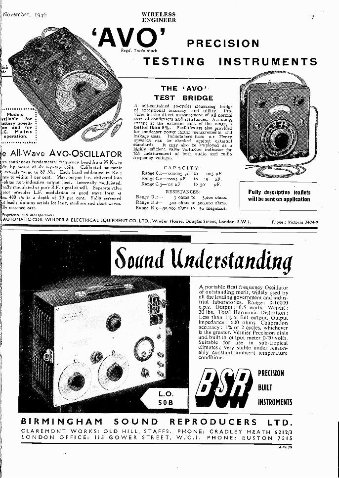
A self-contained 50 -cycles measuring bridgeof exceptional accuracy and utility. Pro-vides for the direct measurement of all normalsizes of condensers and resistances. Accuracy,except at the extreme ends of the range, isbetter than 5%. Facilities are also providedfor condenser power factor measurements andleakage tests. Inductances from o.r Henryupwards can be checked against externalstandards. It may also be employed as ahighly efficient valve voltmeter indicator forthe measurement of both audio and radiofrequency voltages.
CAPACITY:Range C.1-.000005 µF to .005 µF.Range C.2-0005 µF to .5 µF.Range C.3-'o5 µF to 5o
RESISTANCES:Range 5 ohms to 5,000 ohms.Range R.2- 500 ohms to 500,000 ohms.Range R.3-5o,00o ohms to 5o megohms.
Fully descriptive leafletswill be sent on application
roprietore and ManufacturersAUTOMATIC COIL WINDER & ELECTRICAL EQUIPMENT CO. LTD., Winder House, Douglas Street, London, S.W.I. Phone : Victoria 3404-9
,?
Sound UnderstandingA portable Beat frequency Oscillatorof outstanding merit, widely used byall the leading government and indus-trial laboratories. Range : 0-16000c.p.s. Output : 0.5 watts. Weight :30 lbs. Total Harmonic Distortion :Less than 1% at full output. Outputimpedance : 600 ohms. Calibrationaccuracy : I % or 2 cycles, whicheveris the greater. Vernier Precision dialsand built in output meter 9-20 volts.Suitable for use in sub -tropicalclimates ; very stable under reason-ably constant ambient temperatureconditions.
PRECISION
BUILT
INSTRUMENTS
BIRMINGHAM SOUND REPRODUCERS LTD.CLAREMONT WORKS: OLD HILL, STAFFS. PHONE: CRADLEY HEATH 6212/3LONDON OFFICE: 115 GOWER STREET, PHONE: EUSTON 7515
M -W.72
8 WIRELESSENGINEER
November, 194
TELCOSEALq/a Sealiny -01IevWhere strain -free metal -to -glass seals are
required the TELCOSEAL range of alloys isunsurpassed. The co-efficients of thermalexpansion are carefully controlled and adaptedto most types of glass as shown below.
ALLOY GLASS
TELCOSEAL I
III
VI
19
,,,,If
BorosilicateLead BorosilicateLead and Lime
Soft LeadSoft Lead and Soda Lime
Available as strip, rod and wire. Further details on request.
THE TELEGRAPH CONSTRUCTION & MAINTENANCE CO. LTD.Founded 1864
Head Me: 22 OLD BROAD. STREET. LONDON, E.C.2. Tel: LONdon Wall 3141Enquiries to: TELCON WORKS, GREENWICH. S.E:i0. Tel: Greenwich mo,,
We don't selltransformers"off the shelf'.
01
There is nothing ready-made "about SAVAGE transformers. Webuild any model up to 5kVA tosuit your exact requirements.This may mean a little extratrouble at first but it is yourguarantee that the finished articlewill fit into your production withthe greatest possible efficiency.
'PURPOSE-BUILT"a vatTRANSFORMERS LTD.e
51, NORTHGATE ST., DEVIZES. Tel.: Devizes 536.
ELECTRICCHAINPULLEYBLOCK
Write for book-let on lifting andshifting or separ-ate catalogue ofconveyors, cranes,and other mech-anical handlingequipment.
GEO. W. KING LTD.,P.E.B. WORKS HITCHIN HERTS.MANCHESTER CENTRAL 3947 NEWCASTLE 24196
HITCHIN 960
GLASGOWDOUGLAS 27989
BEAT FREQUENCY OSCILLAT
LE LAN -for priority requiremenat present. Write for partstating frequency range rec
INSTRUMENTS LTD 2I.JOHN STREET, BEDFORD ROW, LOKITELEPHONE:CHANCERY
Use " Quixo" method of batterytesting. Reliable results guaran-teed. Send for interestingleaflet G2l5, on bat-tery testing.
FOR LABORATORY INSTRUMENTSOR RADIO TEST GEAR-CONTACT/ LABGEA FIXED FREQUENCY AUDIO OSCILLATORI Suitable for Bridge excitation and other purposes where
purity of wave -form and stability are of importance6 Write for specification and lists to
LABGEAR /WILLOW PLACE, CAMBRIDGPhone : 2494. Grams : Labgear, Cambrid
viALTER SWITCHES
ARE MADE FOR
Earl's Court Exhibition Buildings, Earl's Court, London, 5.W.5.FULHAM 6192. 'GRAMS: WALINST, FULROAD, LONDON`rt
C. R. Cusson7
November, 1946 WIRELESSENGINEER 9
'v; 7e specialise in the'production of all typesof Metalised Ceramic:omponents - Her-netic Seals, Sealed
Tag Boards,3ushes, Formers, etc.These are available in;oldered, coppered orilvered finish, accord-ng to requirements.the suitability of anynish is a matterihich we shall be,leased to discuss.
HERMETIC SEAL
TYPE HS 421
Flashover Voltage
overoutsidepath.4.5 KVDC at 20' C.
Flashover Voltage
over inside path3.S KVDC at 20' C.
Small size. Close
assembly. Physi-cally robust. 732.0
Components mode to stondard designor to customers' specific require-
ments. Write for details.
')NITED INSULATOR CO. LTD;akeroft Rd., Tolworth, Surbiton, Surreyqephone : Elmbridge 5241 Telegrams : Calcine!, Surbiton
lInsurpassed In Ceramics
Off theSHELF!
5 -Pin non-reversibleCONNECTORS
DeliveryfromStock
APPLICATIONS.Power Pack to Amplifier - Amplifier to Microphone.Amplifier to Loudspeaker-Amplifier to Record player.
H/T and L/T Inter -chassis connection.
Anywhere, when mains output and other connectionshave to be carried in a multi -core lead.
SPECIFICATION.5 -Pin Flex plug with cord grip -2 mains Pins - up to
5 amps. Bakelite body and cover-non reversible-self locating.
LIST No. L.I258. Price each 3/5.
5 -way Chassis socket-h.gh grade bakelite wafer panels.LIST No. L.33I. Price each 1 /4.
Plugs and sockets have silver-plated and tin-d'ppedsoldering spigots.
BELLING & LEE LTDCAMBRIDGE 'ARTERIAL ROAD, ENFIELD. MIDDX

I 0 WIRELESSENGINEER
November, 1946
0A11114 K 117Oa yore kfrow-
that no other switch has doublecontacts and self alignment ?
ktyore know-that other N.S.F. products include
Paper Capacitors, Mica Capac-itors, Wire -wound Resistors
and Volume Controls ?
* Only genuine whenbearing these PotentNos. 478391, 478392NSF OAK
BRITISH N.S.F. CO. LTD., Keighley, Yorkshire.London Office: 9, Stratford Place, W.I. Phone: MAYfair 4234.
(Sole Licensees of OAK Manufacturing Co. Chicago)
THE WORLD'S GREATEST BOOKSHOP
* OR_ BOOKS* ItNew and second-hand Books on every subject.119-125, CHARING CROSS ROAD, LONDON, W.C.2.
Gerrard 5660 (16 lines) * OPEN 9-5 (inc. Sat.)
FOR RESISTORS WRITE-
Welwyn ElectricalLaboratories LtdWelwyn GardenCity Herts
.0aeitkMOULDED RUBBER SERVICEInvite inquiries. Advice given en
rubber formul for special is
requirements.
THE HARROW RUBBER CO. LTD, MARKET HARBOROUGH
ALL -POWER CONSTANT VOLTAGE H.T. SUPPLIESWe specialise in the design and manufacture ofConstant Voltage Power Supply Units to meetany specification.The illustration shows a typical unit, in our ,
"Industrial Finish," made to a customer's speci-fication.
Catalogue Sheetsdescribing ourrange ofSTANDARDINSTRUMENTSwill be sent on
request.
TRANSFORMERS. We manufacture precision -woundtransformers and chokes of the very highest quality,and our production lay -out is specially designed tocater for small quantity and experimental orders.
ALL - POWER TRANSFORMERS LTD.8a, GLADSTONE ROAD, WIMBLEDON, S.W.19.
'Phone : LIBerty 3303.
LAMINATIONS & SCREENSRADIOMETAL PERMALLOY
SILICON ALLOYS
ELECTRICAL SOUND & TELEVISION PATENTS LTD.12, PEMBROKE STREET', LONDON, N.1
Piezo QUARTZ CRYSTALSfor all applications.
Full details on request.
QUARTZ CRYSTAL CO., LTD.,(Phone : MAL:len 0334.) 63-71, Kingston Rd., New Maiden, SURREY.
LON D EX for RELAYSLEFT. Stepping Relay
a LF,Selector with 12 posi-tion driving mechanismfor A.C. or D.C.
RIGHT. Two Step RelayLF!FS (Heavy Silver Con-tacts). First impulse "on."Second Impulse "off."Also Aerial ChangeoverRelays. Ask for leaflets 106 and 88 'WE
LONDEX LTDMANUFACTURERS OF RELTS
^tt:',.Vsy 201ANERLEY RPAD LONDON1-1-20 s
November, 1946 WIRELESS xiENGINEER
WAVEMETERS
OSCILLATORS
Electrical Standards forResearch and IndustryTesting and Measuring Apparatusfor Communication Engineering
CONDENSERS
INDUCTANCES
RESISTANCES
H. W. SULLIVAN- LIMITED -London,S.E.45
Tel. New Cross 3225 (Private Branch Exchange)
BRIDGE S_CapacitanceInductanceResistance
ALL TYPES-ALL FREQUENCIES-ALL ACCURACIES
lomorrow bean ofdafrd---
Quality reproduction is the Goodmans' traditionestablished in a yesterday when a pioneering spirit
brought achievements outstanding in Sound Repro-uction. Truly a firm foundation for confidencehat Goodmans will assuredly maintain their
and a policy of " best only " in craft and material
-------_.-,,-._,':----..--_.e-.__,-_.-..-,--_----:,-,..__--..:.-:-_-....__ ____-..tradition in developments yet to come.The 12 ins., illustrated, handles 15 watts
it of undistorted power.
OODMANS
FIDELITY
fEICIENEY
INDUSTRIES LIMITED, Lancelot Road, Wembley, Middx.

11 WIRELESSENGINEER
November, 1946
DEPENDABILITYQY2 -100
BEAM
POWER TETRODE
Anode Voltage ... 2000 VAnode Dissipation 100 WMax. Frequency at
full ratings 30 Mc/s.
TYPICAL OPERATING
CHARACTERISTICS
As a Class C R.F. Amplifier andOscillator, operating at 30 Mc/s.Va 2000 VVg2 400 Vla ... 180 mAVin 160 V peakDriving Power 0.5 WOutput power 260 W
FILAMENT-
THORIATED TUNGSTEN
FilamentVoltage 10 V A.C. or D.C.
Filament Current 5.0 A
11111111M1
0 . and here's the reason whyThe characteristics of a thermionic valve area problem of design. The maintenance of thesecharacteristics under long and trying oper-ating conditions is a question of production.At Mullard, where manufacturing methodsand processes keep pace with development,the result is a valve as reliable in service asit is advanced in technique.The QY2-100 Beam Power Tetrode, illustrated
For further developments watch
billimmoimmoimumminimmimmiiimmummmomillmoommo
here, is a valve with a wide variety of applica-tions in the communications and industrialfields. The advantages of its exceptionalpower gain, constant emission and sturdyconstruction are obvious to the discerningdesigner.
MullardTHE MASTER VALVEiiiiilic
-:=.=. Mul 1 and Technical data and advice on the applications of the QY2-100 Beam Power Tetrode can be obtained from :--=.-..--- THE MULLARD WIRELESS SERVICE CO., LTD., TRANSMITTING & INDUSTRIAL VALVE
DEPT., CENTURY HOUSE, SHAFTESBURY AVENUE, LONDON, W.C.2 .-----.=-.---'
(i6i)
111
fiovember, 1946
bik4fr
,
Tht'.0",
WIRELESSENGINEER
ACOUSTICAL RESEARCHHE TANNOY LABORATORY can pro-
vide a skilled and specialised service inthe investigation of all problems connectedwith vibration and sound. This coversmost aspects of acoustical research and isavailable to industry and GovernmentDepartments engaged on priority projects.
\\TAN NOr/
Aeo.. xtAtr:'Vv4,
RESEARCH LABORATORY
GUY R. FOUNTAIN. LTD."THE SOUND PEOPLE''
The engineering resourceswhich produced hundreds ofmillions of Erie components
for war -time needs are nowat your setvice. May weadvise you, quote you, orsend you samples?ERIE RESISTOR LTD.CARLISLE ROAD, THE HYDE,
LONDON, N.W.9.-Telephone : Colindale 8011
FACTORIES : London, EnglandToronto, Canada Erie, Pa., U.S.A.
"TAN NOV",s the registered Trade Mark of
Equipment manufactured byGUY R. FOUNTAIN, LTD.
"THE SOUND PEOPLE"WEST NOR WOOD, S. E.27
and Branches.'Phone - Gipsy Hill 1131
November,
AfocatityTit
S
FOR THE TOUGHJOB
gELIABLE long -lifeservice under severe working
conditions can be expected fromHunts Moulded Mica Capacitors.
Many years of specialisation in
capacitor development and
manufacture guarantee theirexcellence of performance and
quality.
1111-1-Nr-1,CAPACITOR'S
TRADE MARK
MOULDED MICADIELECTRIC
Full details and prices uponrequest- for every capacitorproblem consult Hunts.
A. H. HUNT LTD.LONDON S.W.I8
Established 1901
Printed in Great Britain for the Publishers, ILIFFE & SONS LTD., Dorset House, Stamford Street, 1...onelen,by The Cornwall Press Ltd., Paris Garden, Stamford Street, London, S.E.I.
VOL. 28 No. 278
EditorW. T. COCKING M.I.E.E.
WIRELESSENGINEER
NOV 2 7 /94u. s. PAT ,NT OFPrOk
NOVEMBER 1946.
Managing Editor Technical EditorHUGH S. POCOCK, M.I.E.E. Prof. G. W. 0. HOWE, D.Sc., M.I.E.E.
Editotiol Advisory Board.-F, M. CO1,1;131{00E, 13,Sc (National Physical Laboratory), I,. W. HAYES, Q.E.E.,M.I.E.E. (British Brdadeasting Corporation). Professor E. B. MOULLIN, A.11. NUMFORD, 0.13.E., B.Sc. (Eng.),313.E.E. (oy.o. Engineering Department), R. L. SMITH-ROSE, D.Sc., Ph.D., ALLEY, (National Physical Laboratory).
EDITORIAL
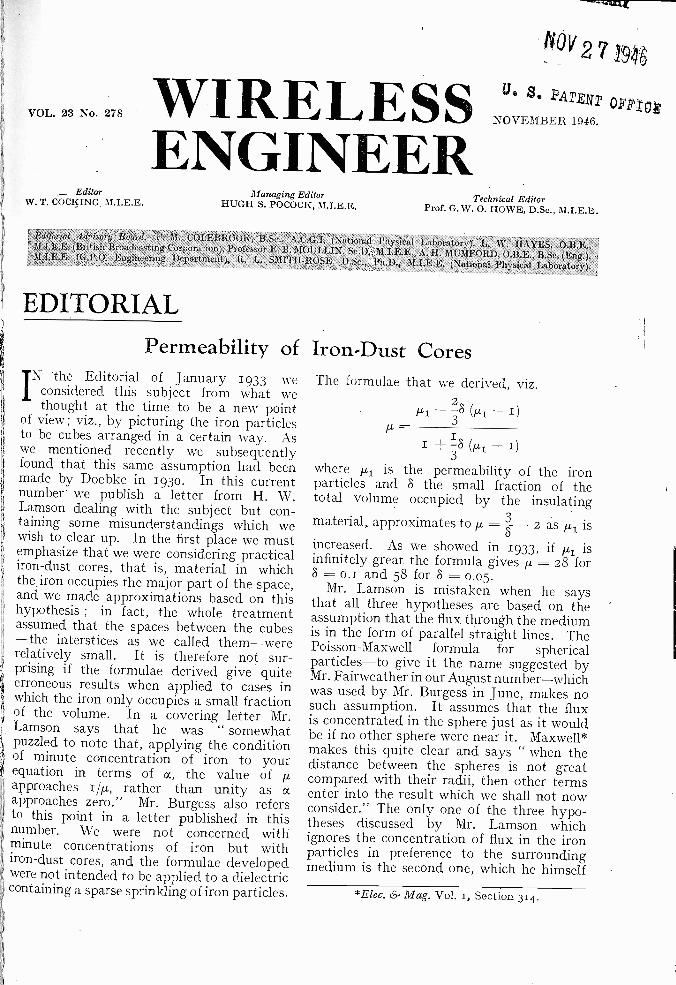
Permeability of Iron -Dust CoresN the Editorial of January 1933 we
considered this subject from what wethought at the time to be a new point
of view; viz., by picturing the iron particlesto be cubes arranged in a certain way. Aswe mentioned recently we subsequently
1 found that this same assumption had beenmade by Doebke in 1930. In this currentnumber we publish a letter from H. W.Lamson dealing with the subject but con-taining some misunderstandings which wewish to clear up. In the first place we mustemphasize that we were considering practicaliron -dust cores, that is, material in whichthe iron occupies the major part of the space,and we made approximations based on thishypothesis ; in fact, the whole treatmentassumed that the spaces between the cubes-the interstices as we called them-wererelatively small. It is therefore not sur-
Y prising if the formulae derived give quiteerroneous results when applied to cases inwhich the iron only occupies a small fractionof the volume. In a covering letter Mr.Lamson says that he was " somewhatpuzzled to note that, applying the conditionof minute concentration of iron to yourequation in terms of a, the value of p,approaches i/p,, rather than unity as aapproaches zero." Mr. Burgess also refersto this point in a letter published in thisnumber. We were not concerned withminute concentrations of iron but withiron -dust cores, and the formulae developedwere not intended to be applied to a dielectric
containing a sparse sprinkling of iron particles.
p -I +
3-8Cul - 1)
where /11 is the permeability of the ironparticles and 8 the small fraction of thetotal volume occupied by the insulatingmaterial, approximates toµ = 3- - 2 as III isincreased. As we showed in 1933, if pt isinfinitely great the formula gives µ, = 28 for8 = o., and 58 for 8 = 0.05.
Mr. Lamson is mistaken when he saysthat all three hypotheses are based on theassumption that the flux through the mediumis in the form of parallel straight lines. ThePoisson -Maxwell formula for sphericalparticles-to give it the name suggested byMr. Fairweather in our August number-whichwas used by Mr. Burgess in June, makes nosuch assumption. It assumes that the fluxis concentrated in the sphere just as it wouldbe if no other sphere were near it. Maxwell*makes this quite clear and says " when thedistance between the spheres is not greatcompared with their radii, then other termsenter into the result which we shall not nowconsider." The only one of the three hypo-theses discussed by Mr. Lamson whichignores the concentration of flux in the ironparticles in preference to the surroundingmedium is the second one, which he himself
The formulae that we derived, viz.
Ft1-38 (Pi - 1)
*Elec. & Mag. Vol. 1, Section 314.
292 WIRELESSENGINEER
November, 1946
IntroductionIN an earlier paper' the author described a
method of terminating complementaryfilters at their common ends in such a
way that the real part of the image imped-ance at these terminals is that of a double -derived section.
When the impedance function is pre-scribed, however, the attenuation function ofthe terminating section is determined.
In the present paper the method isextended to allow more latitude in the choiceof attenuation function when the impedancefunction is prescribed.
Composite FiltersA composite filter is built up as a ladder
network by connecting a number of con-ventional derived -sections in tandem withthe termination. Since the actual impedancelooking in at one end of the filter depends
has suggested. With his so-called randomalignment of cubes the flux density is thesame everywhere, and it is not surprisingthat it gives results entirely different fromthose given by the other two hypotheses. Itis reassuring to note that the other twohypotheses, although so fundamentallydifferent, give results which differ so littlefor practical values of the space -factor.
The large discrepancies between thesecalculated values and the experimentalresults obtained by Legg and Given arevery surprising but very satisfying from apractical point of view. It was rather a pooroutlook for dust cores when it was thoughtthat the permeability, even with the bestmaterial, could not exceed about 5o. In aSpecial Report issued by the Radio ResearchBoard in 1934 and published by the StationeryOffice, entitled " Magnetic Materials atRadio Frequencies," it was stated that " allthe effective permeability formulae . . . .
agree in the main conclusion . . . that afigure of about 8o is the highest practicallyattainable, even with particles of the highestpermeability." If the figures given by Legg
and Given are reliable a dust -core permea-bility of over 15o can now be obtained withparticles of which the permeability is only220, but we must confess that we are notconvinced that such a result can be obtainedif the particles are properly insulated fromeach other. It could be obtained if the ironwere linked up in the form of threads in thedirection of the magnetic field. To take twoextreme cases, laminations normal to theflux, i.e. in effect as in Lamson's hypothesis,would have a resultant permeability equalto pl./DI]. -p - 1)] which for pl = 220and p = 0.9 gives a permeability of 9.6,whereas for the same quantity of iron, thatis, the same value of p, arranged in the formof fine iron wires in the direction of the field,the resultant permeability would be simply
p(µ1 - 1) which is equal to 198.1. Ourformula for cubes gives 24 which seems tous to be more probable than the figure 128.3given by Legg and Given unless the iron islargely in the form of fine threads in thedirection of the field -a very desirableachievement.
G. W. O. H.
DOUBLE.DERIVED TERMINATIONSAn Extension to Filter Theory
By R. 0. Rowlands, B.Sc.(The General Electric Co., Ltd., Coventry).
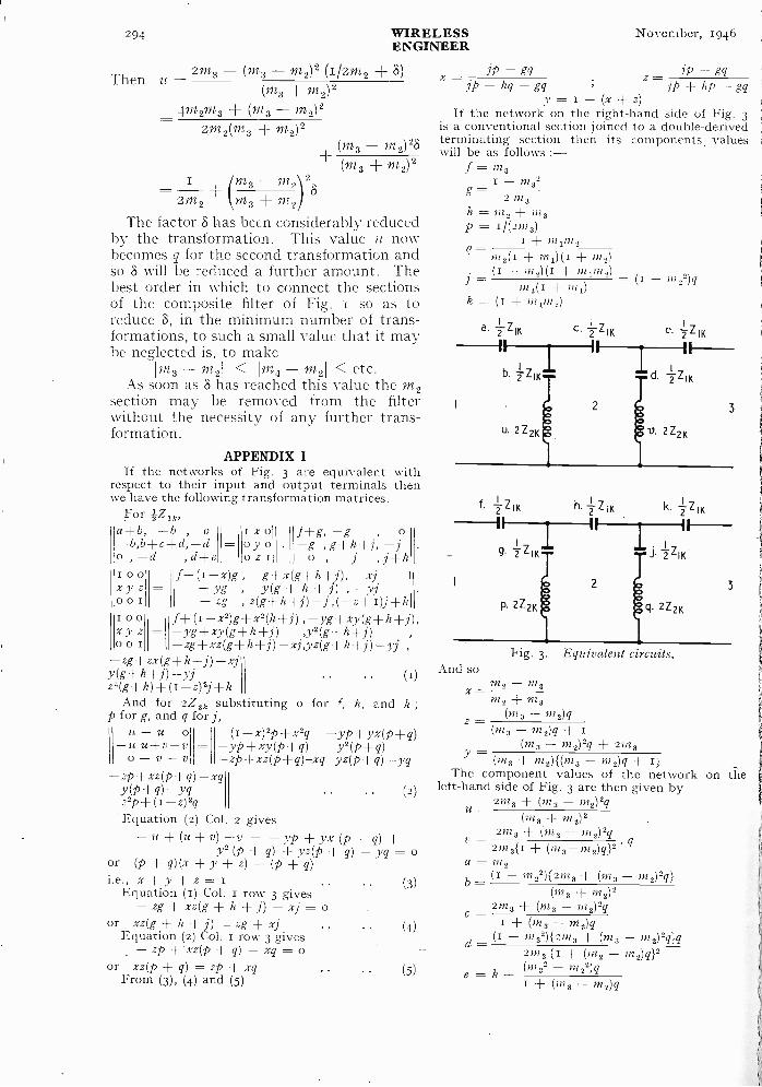
upon the degree of matching at the other end,the filter will normally be terminated witha double -derived half -section at the endremote from the common terminals. The" m " values chosen for the intermediatesections are such that the composite filtergives the required attenuation in its stoprange. A typical filter is shown in Fig. 4,
being the impedance functionwhose real part is equal to Wikm2mi.
The attenuation provided by the termina-tion on the right-hand side is equivalent tothat of a conventional section with in equalto m2, while that provided by the termina-tion on the left-hand side is that of two half-
sections with m values equal to m2, and mitimes m2. The filter, therefore, contains11 sections with in equal to m2. This is un-economical. The problem is therefore howto get rid of a section with in equal to m2
* MS accepted by the Editor, April 1946.
November, 1946 WIRELESSENGINEER 293
from the filter without affecting the imped-ance characteristic.
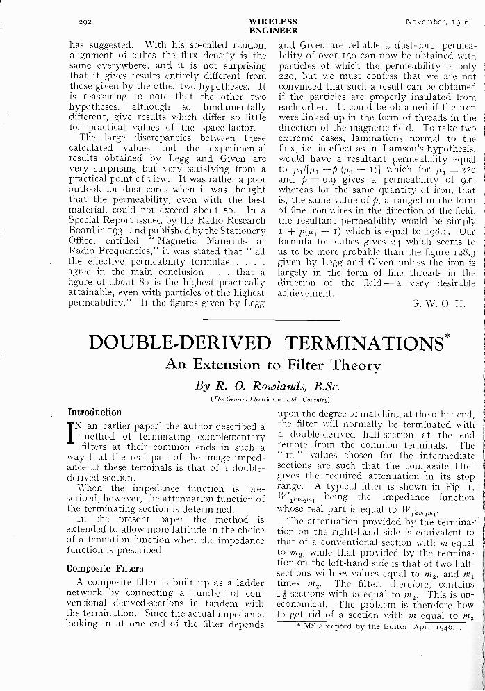
The formulae given in Appendix I enableus to interchange the m2 and m3 sections ofthe filter of Fig. I. The m2 section will nowbe adjacent to a conventional m4 section,and so they can be interchanged by the
A
I
mzrniM2
WIKm2 W - WI K-4.2Km2
Fig. 1.
A
m,
and L3 may, therefore, be taken out of thenetwork and the remaining parts joined withperfect impedance matching at the junction.this means that a whole m2 -section has beenremoved from the network without affectingthe latter's impedance characteristic atTerminals I and B. The composite filterF- ---I I I
M3 m2
-1E7W(K(11210Composite filter; "A " is the remote end," B " is the end at which the filter is connected inparallel with its complement.
/42Km2-- -4-µ,1K 4.WIKm2mi
D
m2
W 2 K m
Fig. z. As Fig 1, but with m2 section moved towards the "A " terminals.
'4 application of the same formula. By n - 2repeated applications the m2 section can bemoved so that it is adjacent to the conven-tional m2 half -section preceding the double -derived half -section.
The filter will now be as shown in Fig. 2.It will be seen that the coefficient of the
component S5 is " a," which is always equalto m2, the value of this coefficient in a con -
0ventional section. If the transferred m2
1 section, the shunt components of which are0 L and S, is split along the dotted line D into
L1 and S1 in parallel with L2 and S2 in sucha way that L1 and S1 are respectively equalto L3 and S3, then the image impedance ofthe half -section comprising S5, S1 and L1 isWik at the junction C and W2km2 at thejunction D. But Wik was the image imped-ance at C before the network was split at D,I so by the theorem proved in Appendix IIthe image impedances looking in both direc-tions at the junction D are equal.
The section comprising L1, S1, S5, S4, S3
B
W (KM zrn
may, therefore, be designed to have aprescribed double -derived impedance func-tion but with latitude in the choice of theattenuation function of all but two half -sections which will have m values of m2 andm1 times m2.
A filter made up of shunt -derived sectionsmay be treated in the same way. The co-efficients of the components " a," " b," etc.,will in this case be the inverse of those forseries -derived sections.
Practical Simplification
It may appear at first sight that in a filterwith many sections the process of trans-ferring the m2 section from one end of thefilter to the other is long and laborious. Inpractice this is not the case, for suppose qdiffers from its value in a conventionalsection by the factor 8 ;
i.e., q =-- - 02722
294 WIRELESS November, 1946ENGINEER
Then u = 2m3 (m3 - M2)2 (I/24/12 + 5)(M3 + M2)2
4m2m3 (m3 - M2)22M2(M3 + )2
+ (m3 -m2)28
(m3 + m2)2I
2m2 M3 + M2
The factor 8 has been considerably reducedby the transformation. This value a nowbecomes q for the second transformation andso 8 will be reduced a further. .amount. Thebest order in which to connect the sectionsof the composite filter of Fig. I so as toreduce 8, in the minimum number of trans-formations, to such a small value that it maybe neglected is, to make
Im3 - m21 < 1m, - m21 < etc.As soon as 5 has reached this value the m2
section may be removed from the filterwithout the necessity of any further trans-formation.
APPENDIX IIf the networks of Fig. 3 are equivalent with
respect to their input and output terminals thenwe have the following transformation matrices.
Fora+b, -b , o i x o f +g, -g , o
oy o -g ,g+h+j, -jo , -d ,d+e ozi o , -j ,j+ki o 01 f+(i-x)g , -g+x(g+h+j), -xjx y - yg , y(g + h +1) , -yjo o it -zg , z(g+h+j)-j ,(-z+i)j+k
x y z -yg+xy(g+h+j) ,y2(g+h+j)f±(1.____,2)8,+,2(h+j),_yg+xy(g+h+j),o o
o o -zg+xz(g+h+j)-xj,yz(g+h+j)-yj-zg+zx(g+h+j)-xjy(g+h+j)-yj .. (I)z2(g+h)±(1-z)2 j+k
And for 2Z2k substituting o for c, h, and k ;p for g, and q for j,
u -u o(I-x)2p+x2q yp ±yx(p-u 14+V -V = --yP+Xy(P+q) Y2(13.-Fq)
0 - v - v -2P+XZ(P+q)-xq yz(p+q)-yq-zp+xz(p+q -xq
z2p + (I -)2qq(2)
Equation (2) Col. 2 gives-u + (u + v) -v = - yp + + q) +
y2 (p + q) + yz(p + q) - yq = oor + q)(x + y + z) q)
i.e., x+y-i-z=1Equation (1) Col. 1 row 3 gives
-zg + xz(g + h + j) -xj = oor xz(g + h + j) zg + xj
Equation (2) Col. i row 3 gives-zp -F'xz(p + q) - xq o
or xz(p + q) zp + xqFrom (3), (4) and (5)
(3)
(4)
(5)
YP - gq - gqx jp - hq - gq z = jp + hp - gqy = -(x+z)If the network on the right-hand side of Fig. 3
is a conventional section joined to a double -derivedterminating section then its components, valueswill be as follows
f = rn,I -m32
g 2 M 3h= rn, + msp = ii(2)72o
I m 1142 2q. = ms(t + ;n2)(1 + m2)
(I - ms)(i + m 022)= m2(I + m1)
k + mim2)
And so
x=
-
(1 - m22)q
Fig. 3 Equivalent circuits.
m2 - m3ms + ms
(m3 m2)4(ms rn2)q +
(ms -J m2)24 + 2)723Y
(m3 + m 2)(m 3 - rn2)q +The component values of the network
left-hand side of Fig. 3 are then given by2m3 (7223 rn2)2q
2423 {1 + (m2 - m2)q}2(n132 m 22)
e = k +I + Ow a - m2)q
u -(m3 + m2)2
2m3 + (ma - m2)24v -2m,{I + (m3-)722)q}2 q
a = msb - (1 -m 22){2m 3 + (m3 -m 2)2q}
(m3 + m3)2c - 2rns + (m3 - rn2)2q
+ (m, - ms)qd - (i - 27232){2m3 + (m3 - m2)2q}4
on the
November, 1946 WIRELESS 295ENGINEERThe above formulae are given in terms of m2,
m3, q and k, and so they may be applied directlyto obtain the first transformation. For the secondand subsequent transformations, all that need bedone is to substitute m4 etc. for m3 and use theappropriate values for q and k.
APPENDIX II
1
[
[
1
(A a -1-- B c) (Ab + Bd)For the network N13, W12 = (Ca ± Dc) (Cb + Dd)So
A B - (A a + B c) (A b + Bd)DC (Ca + Dc)(Cb + Dd)
TheoremIf the four -terminal network N13 of Fig. 4can be -split into two cascade -connected four -
terminal networks Ni, and N23 in such a way thatthe image impedance at terminals a, r' of both N12and N13 is W1, then the image impedances of bothN12 and N23 at terminals 2, 2' are equal.Proof
Le 1 the general circuit parameters of N12 andN23 in matrix form be c D I and a
d then theA B
parameters of N13 are21,,, DB b lcaAa B: Ab B di
Cb,
ABFor the network N12, W12 =CD
i.e., AB{C2ab CD(ad be) D2cd}= CD{A2ab AB(ad be) B2ccil
or ACab(BC - AD) = BDcd(BC - AD)ab BDi.e"cd ACW'2 = W2
N13
2
-w2N12 w;___,. N23
2'
Fig. a.
-4- W3
3'
AcknowledgmentsThe author is grateful to the General
Electric Co. for permission to publish thisarticle, and to his colleague Mr. Li Wei Chenfor helpful criticism.
REFERENCES1 Wireless Engineer, Feb. 1946, the same notation will be usedexcept that m and mi become m2 and ml respectively in the presentarticle.2 See Guillemin's " Communication Networks," Vol. II p. 138,p. 145 and p. 171.
CHARACTERISTICS OF R.F. CABLES*Determination of Impedance and Propagation Constants
By N. C. Stamford, M.Sc.Tech., and R. B. Quarmby, MSc.(Electrotechnics Department, Manchester University)
Introductioni4
DURING the early stages of the war, andbefore more refined techniques, suchas those described elsewhere by Dr.
. Essen, had been developed, the need aroseor measurements at about 600 Mc/s of the
phase and attenuation constants and the:haracteristic impedance of the Polythenensulated cables which were finding wide
,"pplication in radiolocation equipments.For this purpose a technique was developedhich was fundamental in principle and
'' -equired only simple apparatus, and althoughhas now been superseded it would still
.eem to be advantageous for use in thestruction of students. The technique is
equally applicable to coaxial- or twin -typetables and the frequency of 600 Mc/s happens:o be a very convenient one at which to carryut the measurements.
* MS. accepted by the Editor, April 1946.
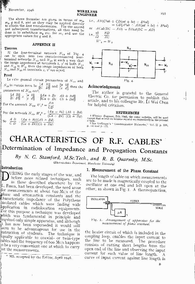
1. Measurement of the Phase ConstantThe length of cable on which measurements
are to be made is magnetically coupled to theoscillator at one end and left open at theother, as shown in Fig. Z. A thermojunction,
OSCILLATORFEEDER
µA
1 iiiiii 1111SCALE
Fig. 1. Arrangemen of apparatus for themeasurement of phase constant.
the heater circuit of which is included in thecoupling loop, enables the input current tothe line to be measured. The procedureconsists of cutting short lengths from theopen end of the line and observing the inputcurrent for each value of line length. Acurve of input current against line length is

296 WIRELESSENGINEER
November, 1946
plotted as the readings are taken, so that thesize of the cut can be varied according to thesteepness of the curve.
The input current is governed by the valueof the input impedance of the line, namelyZo . coth (a + /13)/, where Zo is the charac-teristic impedance of 90
the line, a the attenu-ation constant, 13 thephase constant, and 1the line length. This im-pedance passes throughmaxima for linelengths which are evenmultiples of one -quarterof a wavelength andthrough minima for linelengths which are oddmultiples. The, inputcurrent remains sens-ibly constant while theline impedance is lowcompared with thesource impedance andfalls sharply when theline impedance ap-proaches a maximumvalue. The actual shape of the curve de-pends, of course, not only on the cableitself but also on the magnitude and phaseof the coupling loop impedance. A typicalcurve is shown in Fig. 2.
Since the amount cut off between successiveminima is a half -wavelength for the velocityof propagation in the line, it correspondsto a phase change of 7T radians. Thus ifA and B are successive minima and x1 is thedistance in cm between them, the phaseconstant 13 is given by the relationship :
= 7r/x/ radians/cm .. (t)
In the curve of Fig. 2, for example, theminima occur at line lengths of 237.3 and257.3 cm respectively. The distance x1 istherefore 20.0 cm and the value of /3 is71-/2o.o = o.157 radian/cm.
Greater accuracy in the determination ofthe phase constant may be attained bymaking measurements over a number ofhalf -wavelengths so that if the length ofcable between (n 1) minima, having nmaxima between them, is xn cm the phaseconstant is :
= nn-/xn radian/cm (2)and an error in the location of one of theminima produces only (i/n)th of this error inthe final answer.
80
70
6
'T't 50
30
20
I0
This increase in accuracy can be obtainedwithout cutting back the line over the fullnumber of half -wavelengths for every sampleof cable tested, if the equivalent length ofthe coupling loop is known. This may bedetermined by a trial experiment in which
B
237-3 257:3
236 240 244 248 252 256 260 264
LINE LENGTH- cm.Fig. 2. Curve of input current against line length for a screened twin feeder.
a length of the cable is cut back through asuccession of minima until very short. Sinceit is then possible to predict with accuracyWhere the first minimum would come, andsince this should be exactly at zero linelength, it is easy to say what equivalentlength of line must be attributed to thecoupling loop. If this length is c cm andthe (n i)th minimum occurs at a linelength of in cm the value of xn which mustbe used in equation (2) is xn = c.The phase constant is then :
+p cradian/cm .. (3)
Where there is any doubt as to the valueof n, this may be found by cutting back theline until two minima are obtained, dividingthe distance between them into the totalline length (corrected for the equivalentlength of the coupling loop), and taking nas the nearest integer.
Consider the curve of Fig. 2 again, inorder to obtain a more accurate figure for 13.A previous experiment had shown theequivalent length of the coupling loop to be2.0 cm for this type of cable. The minimaoccur at line lengths of 237.3 and 257.3 cmwhich, when corrected, become 239.3 and259.3 cm respectively. The separationbetween minima has already been seen to
November, 1946 WIRELESSENGINEER 297
be 20.0 cm, and dividing this into thecorrected line lengths shows that thesecorrespond to 12 and 13 half -wavelengthsrespectively. For the former, the value of13 is thus 127T/239.3 = 0.15784 radian/cmand for the latter, p = 1371/259.3 = 0.15783radian/cm.
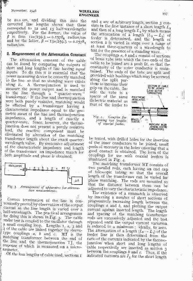
2. Measurement of the Attenuation ConstantThe attenuation constant of the cable
can be found by comparing the outputs ofshort and long lengths of line having equalinputs. To do this it is essential that thepower measuring device be correctly matchedto the line so that no standing wave existsalong it. A thermojunction is used tomeasure the power output and is matchedto the line through a " quarter -wave "transformer. If the line and thermojunctionwere both purely resistive, matching wouldbe effected by a transformer having acharacteristic impedance equal to the geo-metric mean of the line and thermojunctionimpedances, and a length of exactly aquarter -wave. Since, however, the thermo-junction does not, present a purely resistiveload, the reactive component must beeliminated by alteration of the matchingtransformer length about the exact quarter -wavelength value. By successive adjustmentof the characteristic impedance and lengthof the transformer an impedance match forboth amplitude and phase is obtained.
OSCILLATOR II a2b3C4 MT TJ
Fig. 3. Arrangement of apparatus for attenua-tion measurements.
Correct termination of the line is con-veniently proved by observation of the outputcurrent as the line length is varied over ahalf -wavelength. The practical arrangementfor doing this is shown in Fig. 3. The cableunder test is coupled to the oscillator througha small coupling loop. Lengths i , 2, 3 and
_4 of the cable are linked together by sleeve -type couplings a, b and c. MT is thematching transformer between the end ofthe line and the thermojunction TJ, theresponse of which is measured on a micro -ammeter.
Of the four lengths of cable used, sections 1
and 4 are of arbitrary length, section 3 con-sists in the first instance of a short length L1and then of a long length L2 by which meansthe attenuation of a length (L2 - L1) offeeder is determined, and the length ofsection 2 is varied in steps over a range ofat least tliree-quarters of a wavelength totest for the presence of a standing wave.
The couplings a, b and c consist of sectionsof brass tube into which the two ends of thecable to be joined are a push fit, so that thecontinuity of the outer conductor is main-tained. The ends of the tube are split andprovided with bushings which may be screwedalong the split por-tions to increase theirgrip on the cable. In-side the tube is aspacer of the samedielectric material asthat of the feeder to
POLYTHENEINSULATEDCORE
Fig. 4. Coupler forBRASSjoining two lengths SLEEVE -of coaxial feeder.
SECTION OF CABLETO BE JOINED
(LEAD OUTERCONDUCTOR}
MERCURY BLOBJOINING CENTRECONDUCTORS
be tested, with drilled holes for the insertionof the inner conductors to be joined; small
_pools of mercury in the holes ensuring that agood contact is obtained. The form of thecouplings for use with coaxial feeders isillustrated in Fig. 4.
The matching transformer MT consists oftwo parallel rods, each having an end capof telescopic tubing so that the overalllength of the transformer can be varied forphase matching. The rods are mounted sothat the distance between them can beadjusted to vary the characteristic impedance.
The existence of a mismatch is obserVedby inserting a number of short sections ofprogressively increasing length between thecouplings a and b, and plotting the outputcurrent against inserted length. The lengthand, spacing of the matching transformerrods are successively adjusted and the testrepeated until the output current variationis reduced to a minimum ; ideally, to zero.The attenuation of a length (L2 - L1) of thefeeder line is then determined from theratio of the currents indicated by the thermo-junction' when short and long lengths ofcable respectively are inserted as section 3between the couplings b and c. Thus, if theindicated currents are 1.1 for the short length

298 WIRELESSENGINEER
November, 1946
of L1 cm and /2 for the long length of L2 cmthe attenuation constant is given by therelationship :
20 login (/2//1)(L2 - L1)
= decibels/cm
3. Measurement of Characteristic ImpedanceThe characteristic impedance of the cable
is determined using a simple variation of thearrangement used for the measurement ofattenuation. In this connection, it hasalready been explained how, when all foursections of the line are of the same character-istic impedance, the thermojunction can bematched to give a substantially constantoutput current as the length of the line isvaried incrementally in section 2, Fig. 3.
If section 3 of the system is now replacedby a quarter -wavelength of line. having acharacteristic impedance different from thatof the cable, then, due to the transformeraction of this section, the line beyond thecoupling b no longer satisfies the conditionsfor correct termination and variation of thelength of section 2 produces variations in theoutput current.
The first step in the practical procedure isto form all sections of the line from the cableunder test and to adjust the matching of thethermojunction as for an attenuation mea-surement.
Section 3 is then replaced by a quarter -wavelength device of which the characteristicimpedance can be varied systematically,and for each value of this characteristicimpedance the output current variation isobserved as the length of section 2 is changed.For one value of the characteristic impedancethere will be no output current variation forsmall changes in the length of section 2 andthis gives the desired cable impedance.
Fig. 5. Air -spaced coaxial line with detachableend pieces and centre conductor of variable
diameter.
For measurements on coaxial cables asuitable form for this quarter -wavelengthdevice is obtained by using air -spaced co-axial tubes, the impedance variation beingeffected by changing the diameter of the
centre conductor. Satisfactory attachmentto the test cable can be made by means ofend pieces in the manner shown in Fig. 5.For twin feeders, quarter -wavelength lineshaving variable spacing may be used.
AcknowledgmentThe technique described was developed
during 1940-41 in the ElectrotechnicsLaboratories of the Victoria University ofManchester in a Research Group under thedirection of Professor Willis Jackson towhom due acknowledgment is made.
BOOKS RECEIVEDRadio Valve Vade-Mecum, 1946, 6th Edition.
Pp. 232 + xii. Published by P, H. Brans, 28,rue du Prince Leopold, Anvers (Borgerhout),Belgium. Distributed by Ritchie Vincent &Telford, Ltd., Harrow, Middx. Price 12s. 6d.(Postage paid.)
This is a new edition of international valve datawhich has been extended by the inclusion of Germanand Italian military types of valves. Valve baseconnections are included as well as characteristics.
The presentation is in tabular form and theexplanatory pages in English.
Quality Through Statistics (2nd Edition).By A. S. Wharton, F.S.S., A.I.I.A. Pp. 62 + iv.
Published by Philips Lamps, Ltd., Century House,Shaftesbury Avenue, London, W.C.2. Price 6s.
Demonstrations of Radio Aids to Civil Aviation.Pp. 8o+ vii. Published by H.M. Stationery Office,
York House, Kingsway, London, W.C.2. Price 5s.Short technical descriptions are given of equip-
ment shown in the United Kingdom by the Re-search and Development Establishments of theMinistry of Supply during the demonstrations givenon behalf of the Provisional International CivilAviation Organization.
Institute of PhysicsAMEETING of the Electronics Group of the
Institute of Physics will be held on Friday,November 8th, 1946, at 7 p.m., at the LectureTheatre, New Physics Building, The University,Oxford Road, Manchester.
The subject will be " Contact Potentials," byDr. F. A. Vick.
CORRECTIONTwo errors occurred in the advertisement pages
of Wireless Engineer for October 1946. In-advertently, the price of the M.I.P. Series 100Multi -Range Test Set adyertised by MeasuringInstruments (Pullin) Ltd., was given as £8, insteadof the correct figure of L8 los. od.
The 15in Goodmans Industries Ltd. loudspeakeradvertised in the same issue was quoted as TypeT2/1205/15. This should have read T1o/15o1/15.
November, 1946 WIRELESSENGINEER 299
Introduction
T
HE use of the dynatron as a means ofmeasuring audio- and low radio -frequency resistance is well known,
and has been developed by several workers3,10, 14, 15, 16. Apparently, however, the use-fulness of this method has not been extendedto the higher frequencies, although some workhas been done with the dynatron at fre-quencies up to 25 Mc/s. The ease with whichmeasurements of the dynamic resistance oftuned circuits may be made suggests thatthe dynatron would be a very useful tool atthe higher radio frequencies if more wereknown about its properties in those regions.The work described below was carried outin an attempt to make the dynatron avail-able for use at frequencies up to ioo Mc/s.
1. Review of Previous WorkThe earliest applications of the dynatron
at high radio frequencies lay in its use as anoscillator rather than a measuring device.In 1925 Gill and Morre116 constructed anoscillator using a tungsten -filament triode,the control grid having a high positivepotential applied to it. The oscillator madeuse of secondary emission from the anode,but was not a true dynatron, as the grid wasnot held at a constant potential. In thiscircuit, the finite transit time of the electronswas said to give rise to irregularities above10 Mc/s, but it appears unwise to draw anyrigid conclusions from this work, in view ofthe unorthodox nature of the valve andcircuit.
In 1931 Colebrook' used a tetrode asdynatron with a resonant circuit tuned to20 Mc/s. Calculation showed that thezero -frequency differential resistance of thevalve was numerically much smaller thanthe positive dynamic resistance of the tunedcircuit, thus indicating an abnormal effect.No explanation was then attempted.
At about this time the dynatron was used
MS accepted by the Editor, April 1946.
NEGATIVE RESISTANCE CIRCUITELEMENT*
The Dynatron at High Radio FrequenciesBy G. A. Hay, M.Sc., A.M.Brit.I.R.E.
(The Radiotherapy Centre at Leeds)
as a measuring instrument by Iinumal°, whohad previously compared its results atfrequencies up to 8 Mc/s with those givenby other methods, and had found closecoincidence. It was then used for measure-ments up to 25 Mc/s, but no adequate com-parisons seem to have been made at thesefrequencies, beyond a few measurementsusing the series -resistance variation method,from which agreement was found with atolerance of io%. This author neglectsdielectric losses in the valve, and althoughthey may have been small in the particularspecimen used, they have been found veryimportant in the present work, being of thesame order of magnitude as the negativeresistance itself at 5o Mc/s or more. Theresults, however, suggest the type ofbehaviour to be expected, and have been fullyconfirmed in the present work.
In 1938 the operation of a triode dynatronas a generator of ultra -short waves wasinvestigated by Meinke11,12. In this workthe space current was used as a measure ofnegative resistance (as negative conductanceis proportional to space current). Irregu-larities in behaviour were found atfrequencies of the order of 3o to 5o Mc/s,and these were attributed to transit timeeffects. It is interesting to note that thisauthor has fully realized the necessity forchokes isolating the r.f. circuits frompower supplies, a precaution which wasfound essential in the present work. Healso used large bypass capacitors built intothe valve so that all electrodes except theanode should be truly at cathode potentialfor radio -frequencies.
Finally, the nature of dynatron negativeimpedance was investigated in 1943 byChakravarti and Das.2 Here the dynatronwas regarded as an unknown impedance, andthe magnitude of its resistance componentfound by a triple current method, usingthermocouple meters and a standard resist-ance. The difficulties and errors in such amethod must have been great, and this is

300 WIRELESS November, 1946ENGINEER
reflected in the results obtained, as in onespecimen series of measurements, the numeri-cal value of the negative resistance decreasedirregularly from 15 k[1 at 3 Mc/s to a fewhundred ohms at 3o Mc/s and then wentactually positive at 40 Mc/s. The writerfeels that more precise information is neces-sary to substantiate the results claimedfrom this work.
Although no further practical work on thedynatron appears to have been published, atheoretical analysis appeared in 1938 byViti." In this is emphasized the change inconductance due to dielectric losses in thevalve, and also the fact that the interelectrodecapacitance forms part of the tuned circuitand may change with frequency. Secondly,the effects of lead inductance are analysed,and it is concluded that the most importantof these is the feeding back to the controlgrid of an appreciable fraction of the anodevoltage. This occurs because the grid can-not be bypassed completely to cathodebecause of the grid -lead inductance, and so itacquires an oscillatory potential relative tocathode, which then varies the negativeresistance periodically. From an analysisof this effect the author deduces that if theseries -resonant frequency of the grid circuitis of the order of 30o Mc/s, the valve will beusable as a measuring instrument up toabout 15o Mc/s. This, of course, disregardstransit time effects, and attributes any lossin performance to circuit limitations only.
2. Optimum Working Conditions
The measurement of dynamic resistancewith the dynatron at low radio frequencieshas been fully treated elsewhere 14.15.16, butthere are some facts which are not generallyappreciated ; these are enumerated below.
The process of measurement consists oftwo parts : (a) the neutralizing of a positivedynamic resistance by the negative differen-tial resistance of the valve, and (b). themeasurement of the negative resistance by abridge method at i,000 c/s, which may safelyhe assumed equal to the zero -frequencyvalue. One must first choose a suitableworking point. It is necessary that thegrowth of oscillation should be limited to asmall value, less than one volt peak, bycorrect choice of the shape of the character-istic, and this will occur at a point of inflexionin the Ia - Va curve where the gradient
dIa'
of the curve,dV- is a negative maximum.15
a
Most tetrodes and pentodes have a convenientknee in the characteristic at an anode voltageof about io volts (Fig. I), and the proximityof the first bend limits the amplitude to asmall value. In addition, the slope of thecurve at this point is large, giving a satis-factorily small value of negative resistancefor neutralizing bad tuned circuits. Further,it is necessary that the amplitude of theL000-c/s voltage applied from the negative -resistance bridge in (b) should be approxi-mately the same as the r.f. signal, as if itwere to sweep over a different length ofcurve the average negative resistance wouldbe different.
2
1
Id mA 0
20
60V
120V
180 TO240V
20 40 60
Va VOLTS
80 100
Fig. r. Static characteristics of AC /SG for acathode current of to mA.
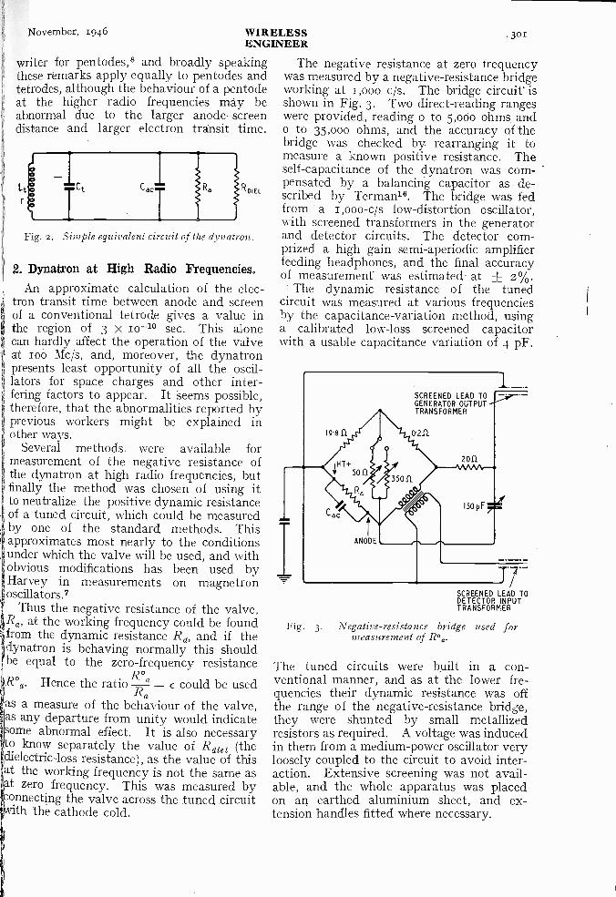
In practice such resistance measurementsare complicated by two other effects : (I)the anode-earth capacitance Cagy, and (2)the dielectric losses due to glass bulb, micasupports, etc. The equivalent circuit isshown in Fig. 2, and it is important to notethat Rdiei, representing the dielectric losses,will vary with frequency. Its value musttherefore be known at all frequencies. Atnormal frequencies the anode-earth capaci-tance will be unimportant, but at higherfrequencies it becomes comparable with themain circuit capacitance and its presencewill be troublesome. Moreover, the effec-tive anode-earth capacitance looking into thedynatron terminals will vary at the higherfrequencies due to the presence of lead induc-tance in the valve.
The most useful valve for measurementpurposes is the tetrode, although a pentodemay be used with suppressor grid connectedto screen. The optimum operating condi-tions have been discussed by the present
November, 1946 WIRELESSENGINEER
301
writer for pentodes,8 and broadly speakingthese remarks apply equally to pentodes andtetrodes, although the behaviour of a pentodeat the higher radio frequencies may beabnormal due to the larger anode-screendistance and larger electron transit time.
L
rROIEL
Fig. 2. Simple equivalent circuit of the dynatron.
2. Dynatron at High Radio Frequencies.An approximate calculation of the elec-
tron transit time between anode and screenof a conventional tetrode gives a value inthe region of 3 X ro-1° sec. This alonecan hardly affect the operation of the valveat roo Mc/s, and, moreover, the dynatronpresents least opportunity of all the oscil-lators for space charges and other inter-fering factors to appear. It seems possible,therefore, that the abnormalities reported byprevious workers might be explained inother ways.
Several methods were available formeasurement of the negative resistance ofthe dynatron at high radio frequencies, butfinally the method was chosen of using itto neutralize the positive dynamic resistanceof a tuned circuit, which could be measuredby one of the standard methods. Thisapproximates most nearly to the conditionsunder which the valve will be used, and withI obvious modifications has been used byHarvey in measurements on magnetronoscillators.?
Thus the negative resistance of the valve,Ra, at the working frequency could be foundfrom the dynamic resistance Rd, and if thedynatron is behaving normally this shouldbe equal to the zero -frequency resistance
R°R°a. Hence the ratioR
= e could be usedRdas a measure of the behaviour of the valve,as any departure from unity would indicateome abnormal effect. It is also necessary
to know separately the value of R dia (thedielectric -loss resistance), as the value of thisat the working frequency is not the same asat zero frequency. This was measured byconnecting the valve across the tuned circuitwith the cathode cold.
The negative resistance at zero frequencywas measured by a negative -resistance bridgeworking at i,000 c/s. The bridge circuit' isshown in Fig. 3. Two direct -reading rangeswere provided, reading o to 5,000 ohms ando to 35,000 ohms, and the accuracy of thebridge was checked by rearranging it tomeasure a known positive resistance. Theself -capacitance of the dynatron was com-pensated by a balancing capacitor as de-scribed by Terman16. The bridge was fedfrom a r,000-c/s low -distortion oscillator,with screened transformers in the generatorand detector circuits. The detector corn -prized a high gain semi-aperiodic amplifierfeeding headphones, and the final accuracyof measurement was estimated at + z%.
The dynamic resistance of the tunedcircuit was measured at various frequenciesby the capacitance -variation method, usinga calibrated low -loss screened capacitorwith a usable capacitance variation of 4 pF.
SCREENED LEAD TOGENERATOR OUTPUTTRANSFORMER
SCREENED LEAD TODETECTOR INPUTTRANSFORMER
Fig. 3. Negative -resistance bridge used formeasurement of Roa.
The tuned circuits were built in a con-ventional manner, and as at the lower fre-quencies their dynamic resistance was offthe range of the negative -resistance bridge,they were shunted by small metallizedresistors as required. A voltage was inducedin them from a medium -power oscillator veryloosely coupled to the circuit to avoid inter-action. Extensive screening was not avail-able, and the whole apparatus was placedon an earthed aluminium sheet, and ex-tension handles fitted where necessary.
302 WIRELESSENGINEER
November, 1946
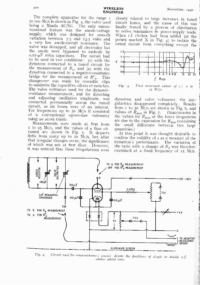
The complete apparatus for the rangeto zoo Mc/s is shown in Fig. 4, the valve usedbeing a Mazda AC/SG. The only uncon-ventional feature was the anode -voltagesupply, which was designed for smoothvariation between 7.5 and 13.5 volts anda very low anode -circuit resistance. Thevalve was decapped, and all electrodes butthe anode were bypassed to cathode byo.oi-p.F mica capacitors. The circuit hadto be used in two conditions : (1) with thedynatron connected to a tuned circuit forthe measurement of Ra, and (z) with thedynatron connected to a negative -resistancebridge for the measurement of R°a. Thischangeover was made by crocodile clipsto minimize the capacitive effects of switches.The valve voltmeter used for the dynamic -resistance measurement, and for detectingand adjusting oscillation amplitude, wasconnected permanently across the tunedcircuit, as its losses were of no interest.For frequencies up to 5o Mc/s it consistedof a conventional square -law voltmeterusing an acorn triode.
Measurements were made at first fromI to 25 Mc/s, and the values of e thus ob-tained are shown in Fig. 5. It departslittle from unity up to io Mc/s, but afterthat irregular changes occur, the significanceof which was not at first clear. However,it was noticed that these irregularities were
5pF MEASURINGCONDENSER 0-014F
b
TO b FOR Ra MEASUREMENT
TO a FOR R%
MEASUREMENT
r -
L
Oa
closely related to large increases in tunedcircuit losses, and the cause of this wasfinally traced by a process of eliminationto series resonances in power -supply leads.When r.f. chokes had been added (at thepoints marked X in Fig. 4) to isolate thetuned circuit from everything except the
1.2
E
('9
O'R
0
2 3 4 5 6 7 8 9 10
f Mcis
15 20
Fig. 5. First measured values of e ; 1 to25 Mc/s.
25
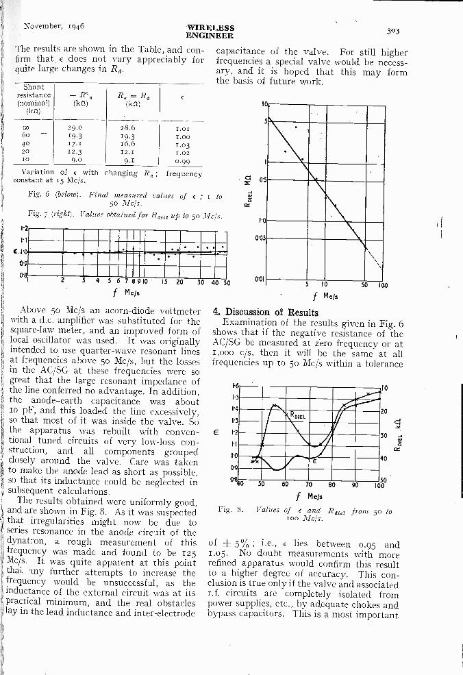
dynatron and valve voltmeter, the irre-gularities disappeared completely. Resultsfrom i to 5o Mc/s are shown in Fig. 6, andvalues of Rdiez in Fig. 7. (Inaccuracies inthe values for Rdie' at the lower frequenciesare due to the expression for R die' containingthe small difference between two largequantities.)
At this point it was thought desirable toconfirm the validity of E as a measure of thedynatron's performance. The variation ofthe ratio with a change of Rd was thereforeexamined at a fixed frequency of 15 Mc/s.
TO a FOR Rd MEASUREMENTOFF FOR ea MEASUREMENT
0'2M51
0-01p,F
4V75V- -
I5V
T
ALUMINIUM SCREEN
+120 -180 V
+6V
TO NEGATIVERESISTANCE
"ANODE,sBRIDGE
Fig. 4. Circuit used for measurements : crosses denote the positions of single or double r.f.chokes added later.
November, 1946 WIRELESS 303ENGINEER
The results are shown in the Table, and con-firm that e does not vary appreciably forquite large changes in Rd.
Shuntresistance(nominal)
(at)
-(kn)
Ra=Rd(k11)
co 29.0 28.6 1.016o 19.3 19.3 I.0040 17.1 16.6 1.0320 12.3 12.1 1.0210 9.0 9.1 0.99
capacitance of the valve. For still higherfrequencies a special valve would be necess-ary, and it is hoped that this may formthe basis of future work.
Variation of e with changing Ra; frequencyconstant at 15 Mc/s.
Fig. 6 (below). Final measured values of e ; i to5o Mc/s.
Fig. 7 (right). Values obtained for Rdiet up to 5o Mc/s.
12
1 1
C 1.0
0.9
0.82 3 4 5 6 7 8910 15 20
f mcis
Above 5o Mc/s an acorn -diode voltmeterwith a d.c. amplifier was substituted for thesquare -law meter, and an improved form oflocal oscillator was used. It was originallyintended to use quarter -wave resonant linesat frequencies above 5o Mc/s, but the lossesin the AC/SG at these frequencies were sogreat that the large resonant impedance ofthe line conferred no advantage. In addition,the anode-earth capacitance was aboutio pF, and this loaded the line excessively,so that most of it was inside the valve. Sothe apparatus was rebuilt with conven-tional tuned circuits of very low -loss con-struction, and all components groupedclosely around the valve. Care was takento make the anode lead as short as possible,so that its inductance could be neglected insubsequent calculations.
The results obtained were uniformly good,and are shown in Fig. 8. As it was suspectedthat irregularities might now be due toseries resonance in the anode circuit of thedynatron, a rough measurement of thisfrequency was made and found to be 125Mc/s. It was quite apparent at this pointthat. any further attempts to increase thefrequency would be unsuccessful, as theinductance of the external circuit was at itspractical minimum, and the real obstacleslay in the lead inductance and inter -electrode
30 40 50
0.
5
C 0-5
ct
1.0
0-05
5 10
f M cis
4. Discussion of ResultsExamination of the results given in Fig. 6
shows that if the negative resistance of theAC/SG be measured at zero frequency or at1,000 c/s, then it will be the same at allfrequencies up to 5o Mc/s within a tolerance
00150 100
5
q
3RDIEL
1 .1
9
E
a40
Fig. 8.
50
Values
60 70 80
f m cis
of e and Raja from 5o to100 Mc/s.
10
20
30
40
9050
100
of + 5% ; i.e., E lies between 0.95 and1.05. No doubt measurements with morerefined apparatus would confirm this resultto a higher degree of accuracy. This con-clusion is true only if the valve and associatedr.f. circuits are completely isolated frompower supplies, etc., by adequate chokes andbypass capacitors. This is a most important
304 WIRELESSENGINEER
November, 1946
point, and it seems to afford a ready explana-tion for the irregular results obtained byprevious workers.
Above 5o Mc/s irregularities appear in thevalue of e, (Fig. 8), and it was at first supposedthat transit time effects were becoming appar-ent. Measurement of dielectric losses in thevalve, however, showed that these irregu-larities were exactly coincident with suddenincreases in energy absorption by the valve.The first of these occurs at about 56 Mc/s,and it is seen that a decrease in c results.On the other hand, the next large decrease inR diet occurs towards Rio Mc/s and higher, andthis results in an increase in E. It is unlikelythat electron transit time is responsible forthis, and apparently we must look to circuitproperties for the explanation.
This idea has been established for triodeoscillators by Gavin5, who states that fortriodes of normal construction, limitation ofthe maximum frequency is first brought aboutby circuits conditions rather than by transit-time effects. It has already been shown inSect. 3 that the transit time in an AC/SGis roughly equal to one cycle of a 3,000-Mc/soscillation, and therefore should notmaterially influence loo-Mc/s operation.
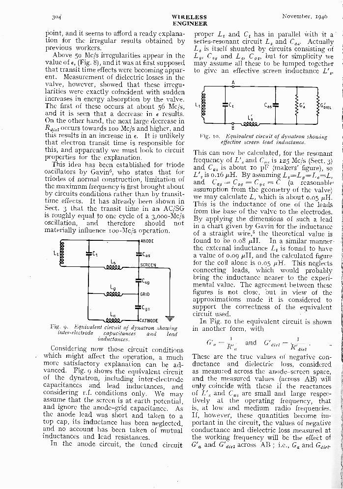
Fig. 9. Equivalent circuit of dynatron showinginter -electrode capacitances and lead
inductances.
Considering now those circuit conditionswhich might affect the operation, a muchmore satisfactory explanation can be ad-vanced. Fig. 9 shows the equivalent circuitof the dynatron, including inter-electrodecapacitances and lead inductances, andconsidering r.f. conditions only. We mayassume that the screen is at earth potential,and ignore the anode-grid capacitance. Asthe anode lead was short and taken to atop cap, its inductance has been neglected,and no account has been taken of mutualinductances and lead resistances.
In the anode circuit, the tuned circuit
proper Li and Ct has in parallel with it aseries -resonant circuit L, and Ca,. ActuallyL, is itself shunted by circuits consisting ofLg, C5g and Lc, C,,, but for simplicity wemay assume all these to be lumped togetherto give an effective screen inductance L's.
A
0Lc 0 C t
00
Fig. so. Equivalent circuit of dynatron showingeffective screen lead inductance.
This can now be calculated, for the resonantfrequency of L', and C is 125 Mc/s (Sect. 3)and Cas is about 10 pF (makers' figure), soL', is 0.16 µH. By assuming L5-=-L9=L6=L,and Ca, = C = C = C (a reasonable,assumption from the geometry of the valve)we may calculate L, which is about 0.05This is the inductance of one of the leadsfrom the base of the valve to the electrodes.By applying the dimensions of such a leadin a chart given by Gavin for the inductanceof a straight wire,5 the theoretical value isfound to be o.o8 p,H. In a similar mannerthe external inductance Li is found to havea value of 0.09 p,H, and the calculated figurefor the coil alone is 0.05 ,uH. This neglectsconnecting leads, which would probablybring the inductance nearer to the experi-mental value. The agreement between thesefigures is not close, but in view of theapproximations made it is considered tosupport the correctness of the equivalentcircuit used.
In Fig. Io the equivalent circuit is shownin another form, with
uEL
R'dielThese are the true values of negative con-ductance and dielectric loss, consideredas measured across the anode-screen space,and the measured values (across AB) willonly coincide with these if the reactancesof L', and Ca, are small and large respec-tively at the operating frequency, thatis, at low and medium radio frequencies.If, however, these quantities become im-portant in the circuit, the values of negativeconductance and dielectric loss measured atthe working frequency will be the effect ofG'. and G'diel across AB ; i.e., G. and G
G' = and G'diel

November, 1946 WIRELESSENGINEER 305
For convenience in manipulation, let usconsider Ga Gera= G, and G' a+ G'diet= G'.At an angular IfreqUency co, the paralleladmittance of the anode-screen space is(G jwCas) and the total admittance of thevalve between A and B is
(G' jcoC as) 111.(01: s
G' jeoCas + IticoLSimplifying and rationalizing we have
G'Y AB
(1 - (.02L' sC as)2 (.02L' s'2G'2
sG'2 Gas(' - (021: sC as)- (1 - w2L'sCas)2 0,2L' ,2G'2At the moment we are mainly interested
in the first term, for this gives the value of Gfor any angular frequency w. Supposefurther that coo is the resonant frequency ofL' and Gas, then coo2L'sCas = r. Hence
IG = G'. (1 ,L,21w02)2 co2L, s2G,2,
but (.02L's2G12 is small,
G = k G' where k - (I 010)092
Gdiel = k.(G'a + aie1) -
Ga = k . G' a, and Gdiet = k . G'dielNow G'diet may be estimated by extra-
polation from Fig. 7, and if k were knownat any frequency, the apparent Gdi01 could becalculated. But k = GaIG'a = R°aIRa = chence Gdie' e G'diel, and this calculatedvalue is compared with the measured value(obtained from Fig. 8) in Fig. ii. From75 Mc/s upwards, although numerical agree-ment is absent, the curves follow exactly thesame trend, and it is apparent that some suchmechanism as outlined above must beresponsible for the behaviour observed.Below 75 Mc/s, however, a sharp peak inGdiej occurs, and to explain this we musthave recourse to a theory advanced by Viti(Sect. 1) in which the grid is said to acquirean oscillatory potential relative to the
`cathode. A positive increase of grid voltagecauses an increase in anode voltage, and soif the feed -back potential is out of phase withthe anode voltage a negative feed -back effectwill be produced and the apparent Ga willbe less. Hence the ratio E = ' will be less
G' athan unity. It is quite impossible to calculatethe magnitude of this effect, as so much maydepend On stray inductive and capacitivecouplings in the circuit and valve, but it maye assumed that the oscillatory control -grid
I
voltage arises because of series resonance inthe grid-cathode circuit, and the resonantfrequency would appear to be about 55 Mc/s.5. Conclusion
It now seems clear that any limitations inthe behaviour of the dynatron up to zoo Mc/s
100
80
60
40
20
B
C
B
G
50 60 70 80
f M els
Fig. 1r. Comparison of measured values of G4i8iwith values obtained from theory : curve A,G' dia obtained by extrapolation from Fig. 7curve B, G diej calculated from G' die? and a ;
curve C, G diel measured.
are not due to transit time effects, but merelyto circuit conditions associated with theconstruction of the valve. Irregularities inbehaviour may also arise as a result ofresonance in power supply leads, etc. Theuse of the dynatron for measuring r.f.resistance at still higher frequencies wouldrequire a special valve designed with theabove considerations in mind.
AcknowledgmentAcknowledgment is due to the University
of Durham for permission to publish thiswork, which was submitted in extended formfor the degree of M.Sc.
REFERENCES1 Colebrook, F.M. : Wireless Engineer, 1931, Vol. 8, p. 581.Chakravarti, S. P. and Das, P. N.: Indian Journal of Physics,
1943, Vol. 17, p. 51.3 Fruhauf, H.: Zeitschrift fit? Hochfrequenztechnik, 1931
Vol. 87, p. 229.4 Gager, F. M. and Russell, J. B.: Proc. Inst. Radio Engrs.,
1935, Vol. 23 p. 1536.5 Gavin, M. R. : Wireless Engineer, 1939, Vol. 16, p. 287.6 Gill, E. W. B. and Morrell, J. H.: Phil. Mag., 1925, Vol. 49,
p. 369.Harvey, A. F.: " High Frequency Thermio,nic Tubes."Hay, G. A.: Wireless World, 1944, Vol. 50, p. 271.
9 Hay, G. A : Electronic Engineering, 1945, Vol. 17, p. 720.1° linuma, H.: Proc. Inst. Radio Engrs., 1931, Vol. 19, p. 467.11 Meinke, H. H.: Hochfrequenztechnik and Elektroakustik, 1937
Vol. 50, p. 50.12 Meinke, H. H.: Hochfrequenztechnik end Elektroakustik, 1938,
Vol. 51, p. 52.la Majewski : Acta Physice Polonica, 1939, Vol. 7, p. 340.14 Scroggie, M. G.: Wireless Engineer, 1933, Vol. 10, p. 527.Is Scroggie, M. G.: " Radio Laboratory Handbook."
'le Terman, F. E.: " Measurements in Radio Engineering."" Tillman, J. R.: Wireless Engineer, 1945, Vol. 22, p. 17.16 Viti, E.: Alta Frequenza, 1938, Vol. 7, p. 536.
90 100

)o() WIRELESS November, 1946ENGINEER
TRANSIENT RESPONSE OF FILTERS*By C. C. Eaglesfield.
(Mallard Radio Valve Company).
IN a recent article Tuckers has discussedthe problem of the transient response offilters. Among other matters he referred
to a " 6 -element symmetrical " filter sectionused between resistive terminations equal toits design resistance, and found its analysisintractable.
The object of this note is to demonstratethat a useful solution is easily obtained if theassumption is made that the pass -band of thefilter is small compared to the mid -frequency.This is a very likely practical case. Theresult obtained confirms the correct form ofthe empirical solution given by Tucker.
For convenience the circuit diagram of thefilter and the proportioning of the elementsare reproduced from Tucker's article. Thus
Fig. r. 6 -element symmetrical filter.
his Fig. 3 becomes Fig. I here, and the listof symbols is :-
In = the derivation parametersa = fractional bandwidth
actual bandwidthmid -band frequency
R = design impedanceThen
m RL1= .
o
RL9 -= .
2n2 coo
I - M2 RL;3-2mn w
nCi -Rwo
2M IC2 = n R02mn
C3 =- I - m2 Rw01 " Transient Response of Filters," by D. G.
Tucker. Wireless Engineer, March 1946, Vol. 23,p. 84.
It may be worth remarking that w0 is themid -band angular frequency. The symbolcol = nw0 is also required.
Tucker's equation (15) gives the outputvoltage (across the right-hand R of Fig. r)due to the applied E0 :-
Output voltslE2 0
+I - M2
m2
+ 2M + I +m` /112 M3' m-112
.. (i)
mwhere M = -
n- - (z)coo
and p is the differential operator dldt.Equation (1) may be written
V = z x Output volts = o[m(p)]. Eo(3)
The problem is to evaluate (3) when E0 is ofthe form
cos coot 1 (4)
that is, the angular frequency w0 modulatedby the Heaviside Unit Function ; or to putit in another way, a sudden application ofcos wet. (The case of the applied angularfrequency differing from w0 will not be con-sidered.)
Equation (3) becomes :-V = 0[M(p)] . eicu4 1 (real part)
= ciwa . 0[M(p + jw0)] . 1 (real part)(4)
This last step is an application of the Heavi-side " Shift " Theorem.
We shall find (with the assumption alreadyreferred to) that
0[M(P ± Iwo)]is real. Assuming this in advance :-
V = cos wet . SP[M(p +Iwo)] 1Thus the envelope of V (call it Ve) is
Ve = 45[M(P /wo)] 1 - (5)
The next step is to evaluate M(fl jw0).
* MS. accepted by the Editor, April 1946.

November, 1946 WIRELESSENGINEER 307
m(p) -=
Therefore
M(P ±iwo)
From equation (2) :-ill y.)2 + 0)09
n a)OP
112 (P +.1w0)2 + 0)02(P + iw 0)
+ 2.iwoP + /coo
nzt 2w1 - jnpw1 col - inP
since nw0 = w1.znip
-->- as n ->- ocoi
Thus for the stated condition, that the pass -band is small compared to the mid -frequency,we may write
M + /*too) =2 mp
w1
Substitute this in equation
ve = rip] 1
(5) :-
Changing the time scale to t' =
the simpler expression :-V, = 45(p)
WI t
2m, we get
.. (6)
Referring to equation (I) for the form of 0,it will be seen that we now have a cubic inin the denominator, instead of a sextic. Wemay thus expect, and shall in fact find, thatequation (6) is easily soluble.
We have
(P) =
I - M2I +7/22 r
-I- 7722 p3+ 2p + +
p2
The solution of (6) is thus the sum of two-1, elementary standard forms, which may be
found in any textbook on operationalcalculus. Reverting to the time variable t,we get
Ve = i - -G c 'sin cotwhere
co,a = -zm
a2 Imo/
Gm
(7)
V 1 - Im2
cu - - +m2.2
Equation (7) may be compared with Tucker'sempirical equation (2r) : it will be found tobe identical, except that he has not evalu-ated G.
If numerical values are inserted in equa-tion (7) corresponding to the measured resultgiven in Tucker's Fig. 5 (Curve 1), it will befound that the agreement is not very good :in particular the calculated curve showsabout io per cent overshoot against themeasured 3 per cent. Tucker states that theQ value of his inductors was zoo. It maybe that this value is not high enough tojustify the neglect of the inductor losses ;
in this analysis the only resistive elementsconsidered are the terminations. Again itmay be that in the measurement the pass-band was not sufficiently small (comparedto the mid -frequency) ; the ratio n was 0.037.
One's physical instinct suggests that boththe inductor losses and the pass -hand were
I - 1n2I -4
7722
p2
(1+p
(1+P
+ p2)
I 7/22p
(p pii2)2 nt2(I im2)
in fact negligible, but it is difficult to thinkof any other cause of the discrepancy.
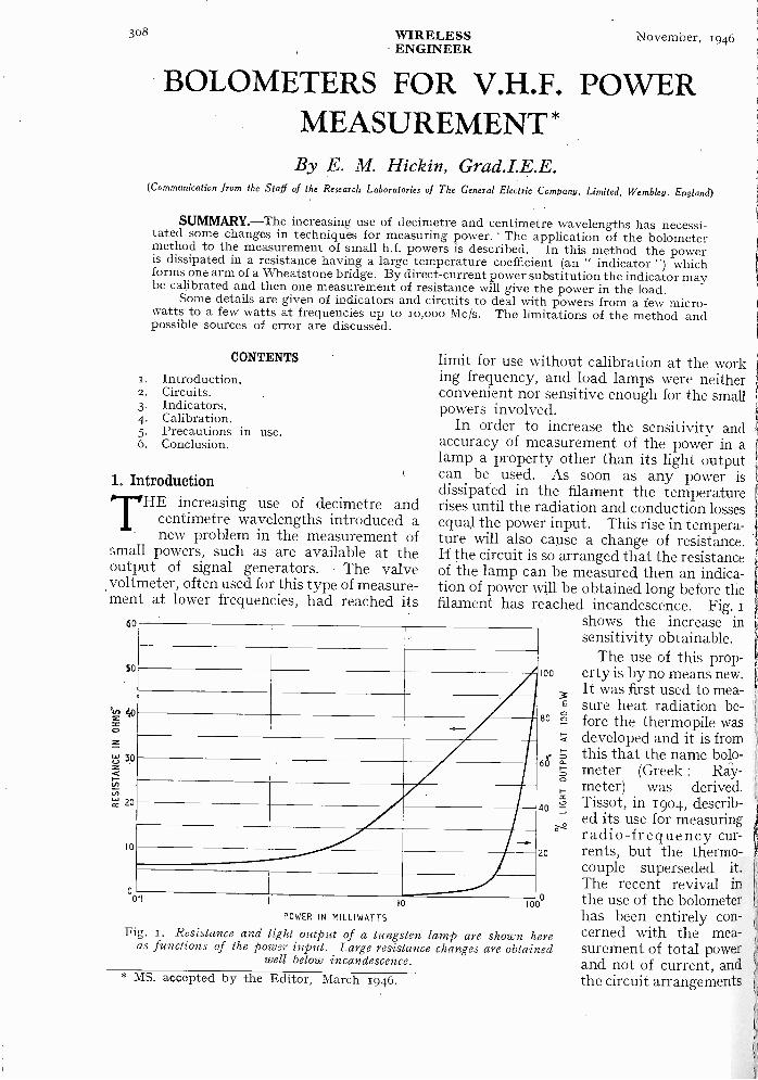
308 WIRELESS November, 1946ENGINEER
BOLOMETERS FOR V.H.F. POWERMEASUREMENT *
By E. M. Hickin, Grad.I.E.E.(Communication from the Staff of the Research Laboratories of The General Electric Company, Limited, Wembley. England)
SUMMARY.-The increasing use of decimetre and centimetre wavelengths has necessi-tated some changes in techniques for measuring power. The application of the bolometermethod to the measurement of small h.f. powers is described. In this method the poweris dissipated in a resistance having a large temperature coefficient (an " indicator ") whichforms one arm of a Wheatstone bridge. By direct -current power substitution the indicator maybe calibrated and then one measurement of resistance will give the power in the load.
Some details are given of indicators and circuits to deal with powers from a few micro -watts to a few watts at frequencies up to 10,000 Mc/s. The limitations of the method andpossible sources of error are discussed.
CONTENTS
1. Introduction.2. Circuits.3. Indicators.4. Calibration.5. Precautions in use.6. Conclusion.
1. IntroductionTHE increasing use of decimetre and
centimetre wavelengths introduced anew problem in the measurement of
small powers, such as are available at theoutput of signal generators. The valvevoltmeter, often used for this type ofmeasure-ment at lower frequencies, had reached its
60
SO
10
limit for use without calibration at the working frequency, and load lamps were neitherconvenient nor sensitive enough for the smallpowers involved.
In order to increase the sensitivity andaccuracy of measurement of the power in alamp a property other than its light outputcan be used. As soon as any power isdissipated in the filament the temperaturerises until the radiation and conduction lossesequal the power input. This rise in tempera-ture will also cause a change of resistance.H the circuit is so arranged that the resistanceof the lamp can be measured then an indica-tion of power will be obtained long before thefilament has reached incandescence. Fig.
shows the increase insensitivity obtainable.
The use of this prop-erty is by no means new.It was first used to mea-sure heat radiation be -
80 s fore the thermopile wasdeveloped and it is fromthis that the name bolo -meter (Greek : Ray -meter) was derived.Tissot, in 1904, describ-ed its use for measuringradio -frequency cur -
20 rents, but the thermo-
0'110
POWER IN MILLIWATTS
Fig. 1. Resistance and light output of a tungsten lamp are shown hereas functions of the power input. Large resistance changes are obtained
well below incandescence.
100
E
o-
60
0Z
40
* MS. accepted by the Editor, March 1946.
100
couple superseded it.The recent revival inthe use of the bolometerhas been entirely con-cerned with the mea-surement of total powerand not of current, andthe circuit arrangements
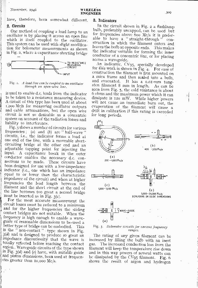
November, 1946 WIRELESSENGINEER 309
1
have, therefore, been somewhat different.2. Circuits
One method of coupling a load lamp to anoscillator is by placing it across an open linewhich is itself coupled to the oscillator.This system can be used with slight modifica-tion for bolometer measurements as shownin. Fig. 2, where a capacitance -shorting bridge
TO .RESISTANCEMEASURING
INPUT
Fig. 2. A load line can be coupled to an oscillatorthrough an open -wire line.
is used to enable d.c. leads from the indicatorto be taken to a resistance measuring device.A circuit of this type has been used at aboutr,000 Mc/s for measuring oscillator outputsand cable attenuations, but the open wirecircuit is not so desirable as a concentricsystem on account of the radiation losses andliability to interference.
Fig. 3 shows a number of circuits for variousfrequencies ; (a) and (b) are " half -wave "circuits, i.e., the indicator forms a load atone end of the line, with a moveable short-circuiting bridge at the other end and anadjustable tapping point for injecting theinput. A capacitance break in the outerconductor enables the necessary d.c. con-nections to be made. These circuits havebeen designed for use with a low -impedanceindicator (i.e., one which has an impedanceequal to or lower than the characteristicimpedance of the circuit) and when at higherfrequencies the lead length between thefilament and the short circuit at the end ofthe line becomes too great a second bridgemust be inserted as in Fig. 3(c).
For the most accurate measurement thecircuit losses must be reduced to a minimumand for the higher frequencies the slidingcontact bridges are not suitable. When thefrequency is high enough to enable a wave -guide of reasonable dimensions to be.used abetter type of bridge can be embodied. Thisis the " non -contact " type shown in Fig.3(d) and is designed to produce so great animpedance discontinuity that the wave istotally reflected before reaching the contactregion. Waveguide circuits of the type shownin Fig. 3(d) and (e) have, with suitable guideand piston dimensions, been used at frequen-cies greater than io,000 Mc/s.
3. IndicatorsIn the circuit shown in Fig. 2 a flashlamp
bulb, preferably uncapped, can be used butfor frequencies above 600 Mc/s it is prefer-able to have a " straight -through ' con-struction in which the filament enters andleaves the bulb at opposite ends. This makesthe indicator suitable for forming the innerconductor of a concentric line, or for placingacross a waveguide.
An indicator, CV95, specially developedfor this work is shown in Fig. 4. For ease ofconstruction the filament is first mounted ona mica frame and then sealed into a bulb,and evacuated. It has a o.oi-mm tung-sten filament 8 mm in length. As can beseen from Fig. 5, the cold resistance is about6 ohms and the maximum power which it candissipate is 120 mW. While higher powerswill not cause an immediate burn out, theevaporation of the filament will cause adrift in calibration if this rating is exceededfor long periods.
(a)200 -1,000 Mc's
(C)1,000- 5,000 Mc/s
(e)Fig. 3. Bolometer circuits for various frequency
ranges.
The rating of any given filament can beincreased by filling the bulb with an inertgas. The increased conduction loss from thefilament will keep the temperature rise downand in this way powers of several watts canbe dissipated by the CV95 filament. Fig. 6shows the result of argon and hydrogen
( b )
400 - f,500 Mc/s
( d )
3,000-20,000 VI*DEPENDING ON GUIDE DIMENSIONS
WAVE -GUIDE
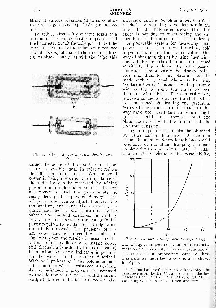
310 WIRELESS Novegiber, 1946ENGINEER
filling at various pressures (thermal conduc-tivities, Argon 0.00004, hydrogen 0.0003at 0° C).
To reduce circulating current losses to aminimum the characteristic impedance ofthe bolometer circuit should equal that of theinput line. Similarly the indicator impedanceshould also equal that of the incoming line,e.g. 75 ohms ; but if, as with the CV95, this
ilIONIOSsaMeraseemeall
Fig. 4. CV95 (R3/1o) indicator showing con-struction.
cannot be achieved it should. be made asnearly as possible equal in order to reducethe effect of circuit losses. When a smallpower is being measured the impedance ofthe indicator can be increased by addingpower from an independent source. If 2-kc/sa.f. power is used the galvanometer iseasily decoupled to prevent damage. Thea.f. power input can be adjusted to give thetemperature, and hence the resistance, re-quired and the r.f. power measured by thesubstitution method described in Sect. 5below ; i.e., by measuring the change in d.c.power required to rebalance the bridge whenthe r.f. is removed. The presence of thea.f. power does not affect the result. InFig. 7 is given the result of measuring theoutput of an oscillator of constant power(fed through a length of attenuating cable)by a bolometer whose indicator impedancecan be varied in the manner described.With no " preheating " the bolometer indi-cates about 3 mW. at a resistance of 15 ohms.As the resistance is progressively increasedby the addition of a.f. power, and the circuitreadjusted, the indicated r.f. power also
increases, until at 60 ohms about 6 mW isreached. A standing wave detector in theinput to the bolometer shows that thiseffect is not due to mismatching and cantherefore be attributed to the circuit losses.
A preferable system for measuring smallpowers is to have an indicator whose coldimpedance is nearer the desired value. Oneway of obtaining this is by using finer wire;this will also have the advantage of increasedsensitivity due to lower thermal capacity.Tungsten cannot easily be drawn below0.01 mm diameter but platinum can bemade with very small diameters by usingWollaston* wire. This consists of a platinumwire coated to some ten times its owndiameter with silver. The composite wireis drawn as fine as convenient and the silveris then etched off, leaving the platinum.Wires of 0.003 -mm platinum made in thisway have, been used and an 8 -mm lengthgives a cold " resistance of about 120ohms compared with the 6 ohms of theo .o -mm tungsten.
Higher impedances can also be obtainedby using carbon filaments. A o.o6-mmcarbon filament of 8 -mm length has a coldresistance of 150 ohms dropping to about90 ohms for an input of 1.5 watts. In addi-tion iron,* by virtue of its permeability,
160
120
80
40
020 40 60 80
OHMS
Fig. 5. Characteristic of indicator type C I70 5.
has a higher impedance than non-magneticmetals as the skin effect is more pronounced.
The result of preheating some of thesefilaments as described above is also shownin Fig. 7.
* The author would like to acknowledge theassistance given by Dr. Chaston (Johnson MattheyResearch Dept.) and Mr. D. W. Chappel (N.P.L.) inobtaining Wollaston and o.oi-mm iron wire.
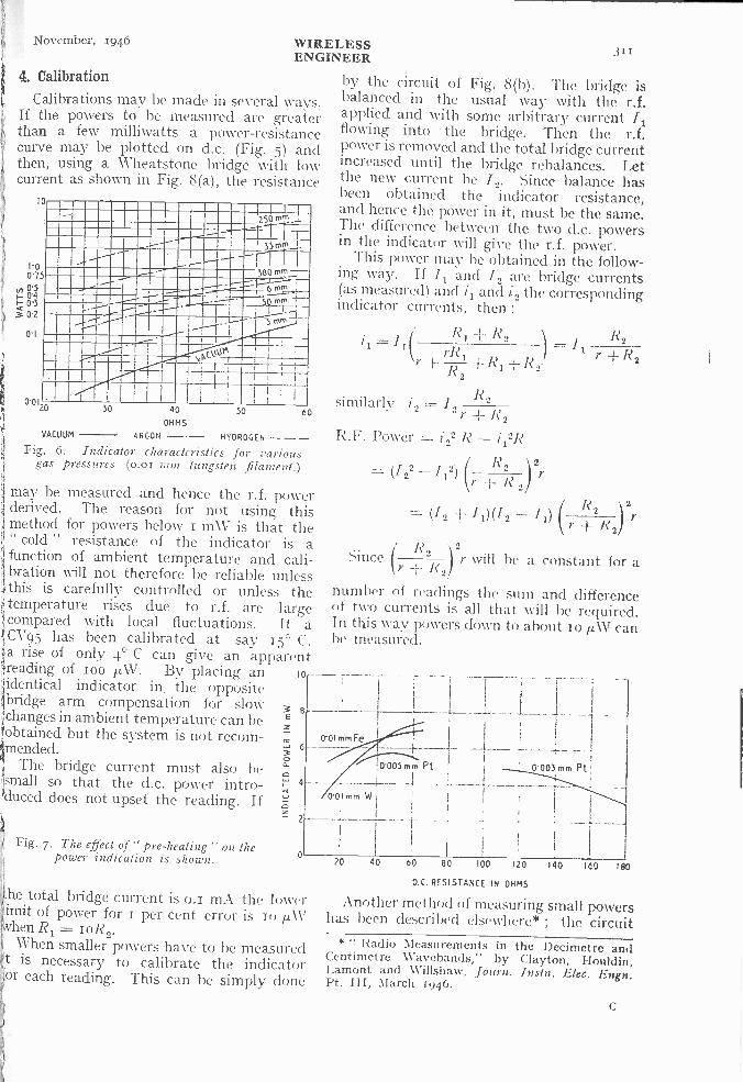
November, 1946 WIRELESSENGINEER 311
4. CalibrationCalibrations may be made in several ways.
If the powers to be measured are greaterthan a few milliwatts a power -resistancecurve may be plotted on d.c. (Fig. 5) andthen, using a Wheatstone bridge with lowcurrent as shown in Fig. 8(a), the resistance
10
100'75
r.
302
0'1
I I2301*,*
1111111111111111 S MN
111111111111....las mm-
1111111111111101 1
mm
ImommommessommitaiumMIIM111111ffra11111111111
0'012030 40 60
OHMS
VACUUM ARGON -- HYDROGEN - --Fig. 6. Indicator characteristics for various
gas pressures (0.01 mm tungsten filament.)
may be measured and hence the r.f. powerderived. The reason for not using thismethod for powers below i inW is that the
11" cold " resistance of the indicator is afunction of ambient temperature and cali-
1 bration will not therefore be reliable unlessthis is carefully controlled or unless thetemperature rises due to r.f. are largecompared with local fluctuations. If aC1795 has been calibrated at say 15° C.a rise of only 4' C can give an apparentreading of ioo it.W. By placing an to
:identical indicator in, the oppositebridge arm compensation for slow
i`changes in ambient temperature can he/obtained but the system is not recom-imended.1, The bridge current must also beIsmail so that the d.c. power intro-duced does not upset the reading. If
Fig. 7. The effect of " pre -heating" on thepower indication is shown.
he total bridge current is o.i mA the lowerimit of power for i per cent error is Io glAthen Ri = ioR2.When smaller powers have to he measured
t is necessary to calibrate the indicatoror each reading. This can be simply done
by the circuit of Fig. 8(b). The bridge isbalanced in the usual way with the r.f.applied and with some arbitrary current /1flowing into the bridge. Then the r.f.power is removed and the total bridge currentincreased until the bridge rebalances. Letthe new current he /2. Since balance hasbeen obtained the indicator resistance,and hence the power in it, must be the same.The difference between the two d.c. powersin the indicator will give the r.f. power.
This power may be obtained in the follow-ing way. If /1 and /2 are bridge currents(as measured) and 11 and 12 the correspondingindicator currents, then :
R,I rR = I
r -I- R1 -1- R2R2
R2
r ± R2
similarly i2 = 12 R2r /?2
R.F. Power = i 22 R - 1121?
R 2(122 -112 2
r)r R 2)
= (/ 2 -I-- 11)(12 - 1:2nyr
Since ( R )2r r will be a constant for aR 2
number of readings the sum and differenceof two currents is all that will be required.In this way powers down to about To i.LW canbe measured.
20 40 60 80 100 120 140 160
D.C. RESISTANCE IN OHMS
Another method of measuring small powershas been described elsewhere* ; the circuit
* " Radio Measurements in the Decimetre andCentimetre Wavebands," by Clayton, Houldin,Lamont and Willshaw, fount. Instn. Elec. Env.Pt. III, March 1946.
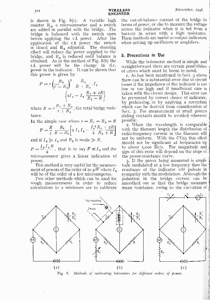
312 WIRELESS November, 1946ENGINEER
is shown in Fig. 8(c). A variable highresistor R4, a microammeter and a switchare added in parallel with the bridge. Thebridge is balanced with the switch openbefore applying the r.f. power. After theapplication of the r.f. power the switchis closed and R4 adjusted. The shuntingeffect will reduce the power supplied to thebridge, and R4 is reduced until balance isobtained. As in the method of Fig. 8(b) ther.f. power will be the change in d.c.power in the indicator. It can be shown thatthis power is given by
R2 2 R3 Ip= + R2) R + R3 4
R3 + 2R{2/2 - /A R3 R
where R = YR1 + 2 the total bridge resis-+ RR2
tance.In the simple case where r = R1 = R2 = R
R
4 R ±R2R2
12 /4/42 R3 ±2 R3 + R
and if /2 /4 and R3 is made R,
p = I2 14R, that is to say P cc /4 and the
2microammeter gives a linear indication ofpower.
This method is very useful for the measure-ment of powers of the order of io µ,W where /4will be of the order of a few microamperes.
Two other methods which can be used forrough measurements in order to reducecalculations to a minimum are to calibrate
P=
PRE -HEATING \
\ kcjs
."
1
(a)
the out -of -balance current of the bridge interms of power, or else to measure the voltageacross the indicator when it is fed from abattery in series with a high resistance.These methods are useful as output indicatorswhen setting up oscillators or amplifiers.
5. Precautions in UseWhile the bolometer method is simple and
straightforward there are certain possibilitiesof errors which must be borne in mind.
1. As has been mentioned in Sect. 3 abovethere can be a substantial error due to circuitlosses if the impedance of the indicator is toolow or too high and if insufficient care istaken with the circuit design. This error canbe prevented by correct choice of indicator, ,
by preheating, or by applying a correctionwhich can be derived from consideration of ti
Sect. 3. For measurement of small powerssliding contacts should be avoided whereverpossible.
2. When the wavelength is comparablewith the filament length the distribution ofradio -frequency current in the filament willnot be uniform. With the CV95 this effectshould not be significant at frequencies upto about 5,000 Mc/s. The magnitude andsign of this error will depend on the slope ofthe power -resistance curve.
3. If the power being measured is ampli-tude modulated at a low frequency then theresistance of the indicator will pulsate insympathy with the modulation. Although thepulsation in the bridge current can besmoothed out so that the bridge measuresmean resistance, owing to the curvature of
III
(b)
R z
R,
(c)
Fig. 8. Methods of calibrating bolometers for different orders of power.

November, 1946 WIRELESSENGINEER 313
0.01SECOND.1
J
R.F. ENVELOPE100 cis
0'06 mm CARBON, IN VACUOL___ (ERROR NEGLIGIBLE)
0.01 mm TUNGSTENIN VACUO
0.005 mm PLATINUMIN AIR
0.003 mm PLATINUMIN AIR
Fig. 9. Pulsation of resistance with amplitudemodulation of carrier.
the power -resistance relationship, if thepulsation is large the mean resistance willnot correspond to the mean power shown bythe d.c. calibration. The effect is quitenoticeable with the CV95 on short pulses of5o c/s repetition rate, but soon becomesnegligible at higher frequencies of repetition.The time of rise and fall of resistance withpulses of r.f. can be measured by passing asteady current through the indicator andamplifying the voltage pulses generatedacross it. When these are viewed on acathode-ray tube the decay time for a CV95with some 30-mW input has been measuredand is about oo25 second ; for ooo5 and00o3 mm platinum (in air) the times areo.006 and 0.002 second respectively. Fig. gshows the type of picture obtained withvarious filaments, and it will be seen that theerror is least with the filament of highestthermal capacity.
4. It should be mentioned that when thickaments are used the heat distribution can
e non -uniform radially due to skin effect.his effect will be more noticeable when the
ilament is of a low heat conductivity.
,). Conclusion
Provided proper account is taken of itsimitations the bolometer is a valuable toolor power measurement at centimetre anddecimetre wavelengths, especially in theange from ioo mW to a few microwatts.
The frequency limit has not yet beenreached ; and for powers of io ,uW and aboveat frequencies up to io,000 Mc/s it hasprovided a good estimate of absolute powerand an accurate method for relative measure-ments.
The work described in this paper wascarried out to meet needs arising in variousresearch and development programmes under-taken on behalf of the Admiralty. Theauthor is indebted to the Board of Admir-alty for permission to publish this paper.
CORRESPONDENCEPermeability of Dust Cores
To the Editor," Wireless Engineer."SIR,-In the June 1946, issue of Wireless Engineer,
Burgess gives a formula (cited below) for the com-putation of the effective permeability eu. of a dustcore composed of ferro-magnetic particles havingan inherent permeability iho and a fractionalconcentration (by volume) of p. This inspired aninvestigation under certain hypothetical conditionswith the following results.
Hypothesis I. Assuming the iron grains to beidentical cubes with corresponding faces parallel,uniformly distributed, and perfectly aligned inrows in three perpendicularshown (Appendix A) that for flux perpendicularto the cube faces the effective permeability of theaggregate core is :
= I + pi:Lo v7,
whence, if pi, > >
= + 3 - . . (2)I - -,pThis alignment of cubical grains was proposed by
Howe, Wireless Engineer, January 1933.Hypothesis II. Assuming the iron grains to be
identical cubes with corresponding faces parallel,uniformly distributed but with random alignment,I have shown (Appendix B) that :
p, = +/40
whence, if /.40> >I
ih Max = I -F I- pHypothesis III. Assuming the iron grains to be
identical spheres uniformly distributed, Burgessgives the value :
(3)
11= 13P+
110 + 2ptto -
whence, if po> >33p/1 -p
(4)
(5)
. (6)
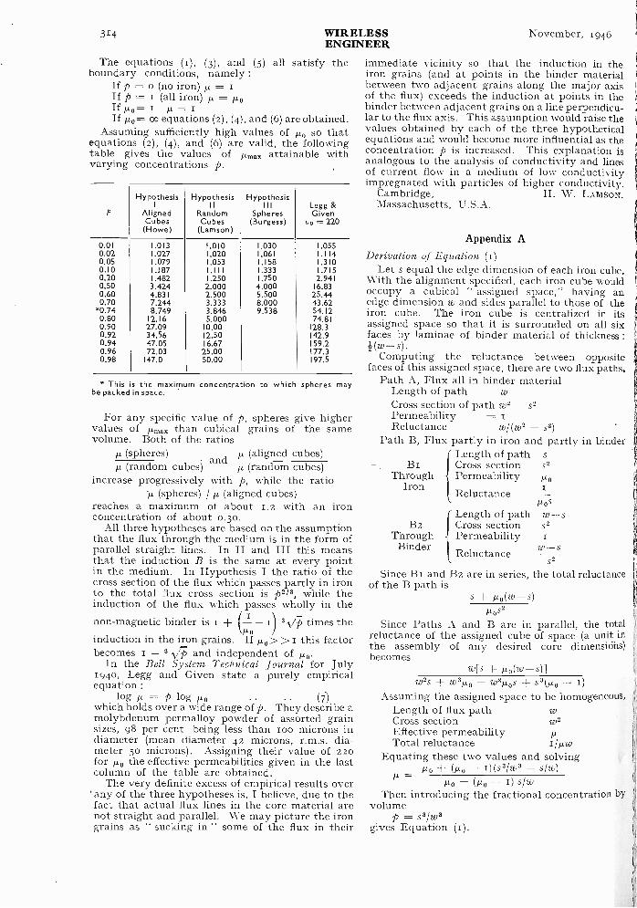
314 WIRELESSENGINEER
November, 1946
The equations (1), (3), and (5) all satisfy theboundary conditions, namely :
If p = o (no iron) tt = IIf p = i (all iron) 1.4. = /20If µ.0= 1 µ =If p,o= oo equations (2), (4), and (6) are obtained.
Assuming sufficiently high values of /.4 so thatequations (2), (4), and (6) are valid, the followingtable gives the values of proax attainable withvarying concentrations p.
P
HypothesisI
AlignedCubes(Howe)
Hypothesis11
RandomCubes
(Lamson)
Hypothesis1 1 1
Spheres(Burgess)
Legg &Given
u. --- 220
0.01 1.013 1.010 1.030 1.0550.02 1.027 1.020 1.061 1.1140.05 1.079 1.053 1.158 1.3100.10 1.187 1.111 1.333 1.7150.20 1.482 1.250 1.750 2.9410.50 3.424 2.000 4.000 16.830.60 4.831 2.500 5.500 25.440.70 7.244 3.333 8.000 43.62
*0.74 8.749 3.846 9.538 54.120.80 12.16 5.000 74.810.90 27.09 10.00 128.30.92 34.56 12.50 142.90.94 47.05 16.67 159.20.96 72.03 25.00 177.30.98 147.0 50.00 197.5
* This is the maximum concentration to which spheres maybe packed in space.
For any specific value of p, spheres give highervalues of /1,$ than cubical grains of the samevolume. Both of the ratios
(spheres) /1 (aligned cubes)(random cubes)
and/2 (random cubes)
increase progressively with p, while the ratio'IL (spheres) / 1.4 (aligned cubes)
reaches a maximum of about 1.2 with an ironconcentration of about o.30.
All three hypotheses are based on the assumptionthat the flux through the medium is in the form ofparallel straight lines. In II and III this meansthat the induction B is the same at every pointin the medium. In Hypothesis I the ratio of thecross section of the flux which passes partly in ironto the total flux cross section is p2/3, while theinduction of the flux which passes wholly in thenon-magnetic binder is (- - 1) 3 VT) times the
/-toinduction in the iron grains. If µ,0> >1 this factorbecomes 1 - 3 -VT, and independent of /10.
In the Bell System Technical Journal for July1940, Legg and Given state a purely empiricalequation :
log II = p log /10 . .
which holds over a wide range of p. They describe amolybdenum permalloy powder of assorted grainsizes, 98 per cent being less than loo microns indiameter (mean diameter 42 microns, r.m.s. dia-meter 5o microns). Assigning their value of 220for tic, the effective permeabilities given in the lastcolumn of the table are obtained.
The very definite excess of empirical results over' any of the three hypotheses is, I believe, due to thefact that actual flux lines in the core material arenot straight and parallel. We may picture the irongrains as " sucking in " some of the flux in their
immediate vicinity so that the induction in theiron grains (and at points in the binder materialbetween two adjacent grains along the major axisof the flux) exceeds the induction at points in thebinder between adjacent grains on a line perpendicu-lar to the flux axis. This assumption would raise thevalues obtained by each of the three hypotheticalequations and would become more influential as theconcentration p is increased. This explanation isanalogous to the analysis of conductivity and linesof current flow in a medium of low conductivityimpregnated with particles of higher conductivity.
Cambridge, H. W. LAMSON.Massachusetts, U.S.A.
Appendix ADerivation of Equation (t)
Let s equal the edge dimension of each iron cube.With the alignment specified, each iron cube wouldoccupy a cubical " assigned space," having anedge dimension w and sides parallel to those of theiron cube. The iron cube is centralized in itsassigned space so that it is surrounded on all sixfaces by laminae of binder material of thickness :
(w -s).Computing the reluctance between opposite
faces of this assigned space, there are two flux paths.Path A, Flux all in binder material
Length of pathCross section of path w2 - s2Permeability =Reluctance w/(w2 s2)
Path B, Flux partly in iron and partly in binder
BiThrough
Iron
{Length of pathCross sectionPermeability
Reluctance
s2
/lo
!Los
B2Length of path w -sCross section s2
Through - PermeabilityBinder w -s
S2
Since B1 and B2 are in series, the total reluctanceof the B path is
Reluctance
s µo(w-s)Pos2
Since Paths A and B are in parallel, the totalreluctance of the assigned cube of space (a unit inthe assembly of any desired core dimensi6ns)becomes
w[s /10(w -s)]w2s w31.40 - w2iLo5 s3(tko -
Assuming the assigned space to be homogeneous,Length of flux pathCross sectionEffective permeabilityTotal reluctance
w
/t/WEquating these two values and solving
/2o + - (s3/w3 - s/w)=
Po- (FLo 1I) siwThen introducing the fractional concentration by
volumep = .s3/w3
gives Equation (I).
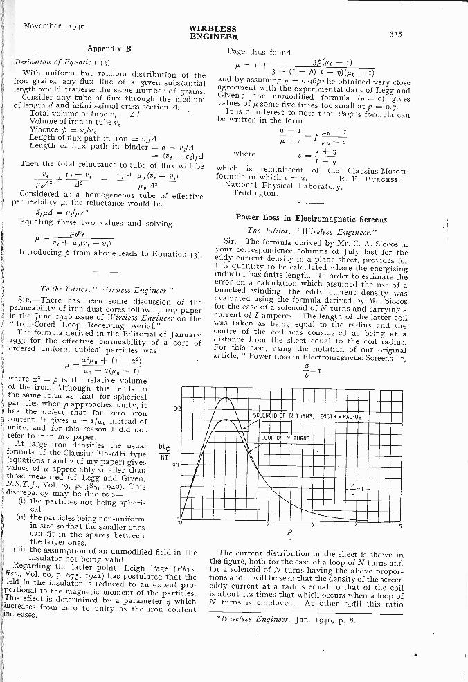
' November, 1946 WIRELESSENGINEER 315
Appendix B
Derivation of Equation (3)With uniform but random distribution of the
iron grains, any flux line of a given substantiallength would traverse the same number of grains.
Consider any tube of flux through the mediumof length d and infinitesimal cross section d.
Total volume of tube vt = [IdVolume of iron in tube v,Whence p = vi/v,Length of flux path in iron = vi/z1Length of flux path in binder = d - vild
= (vt - v,)/z1Then the total reluctance to tube of flux will be
v, tv - vi vi /Jo (v, - vi)P0ZI2
zp =Po ,612
Considered as a homogeneous tube of effectivepermeability the reluctance would be
dhal = vi/µd2Equating these two values and solving
Povt= vi p.o(vi - vi)
Introducing p from above leads to Equation (3).
To the Editor," Wireless Engineer "SIR,-There has been some discussion of the
permeability of iron -dust cores following my paperin the June 1946 issue of Wireless Engineer on the" Iron -Cored Loop Receiving Aerial."
The formula derived in the Editorial of January1933 for the effective permeability of a core ofordered uniform cubical particles was
c(2110 ( - C42)140 a(Po - 1)
where CC3 = p is the relative volumeof the iron. Although this tends tothe same form as that for sphericalparticles when p approaches unity, ithas the defect that for zero ironcontent it gives m. = iitto instead ofunity, and for this reason I did notrefer to it in my paper.
At large iron densities the usual bio,formula of the Clausius-Mosotti type NI1 (equations 1 and 2 of my paper) givesvalues of µ appreciably smaller thanthose measured (cf. Legg and Given,B.S.T.J., Vol. 19, p. 385, 194o). This
I discrepancy may be due to :-0 (i) the particles not being spheri-
cal,(ii) the particles being non -uniform
in size so that the smaller onescan fit in the spaces betweenthe larger ones,
(iii) the assumption of an unmodified field in theinsulator not being valid.
Regarding the latter point, Leigh Page (Phys.Rev., Vol. 6o, p. 675, 1941) has postulated that thefield in the insulator is reduced to an extent pro-portional to the magnetic moment of the particles.This effect is determined by a parameter .71 whichincreases from zero to unity as the iron content increases.
11 -
Page thus foundp, = I + 3P(Po - 1)
3 + (1 - P)(1 - n)(140 - 1)and by assuming 77 = 0.960 he obtained very closeagreement with the experimental data of Legg andGiven ; the unmodified formula (n = o) givesvalues of is some five times too small at p = 0.7.
It is of interest to note that Page's formula canbe written in the form- pc, -
= Pc 1.40
where c -2 ±- rl
which is reminiscent of the Clausius-Mosottiformula in which c = 2. R. E. BURGESS.National Physical Laboratory,
Teddington.
Power Loss in Electromagnetic ScreensThe Editor, " Wireless Engineer."
Sir,-The formula derived by Mr. C. A. Siocos inyour correspondence columns of July last for theeddy current density in a plane sheet, provides forthis quantity to be calculated where the energizinginductor has finite length. In order to estimate theerror on a calculation which assumed the use of abunched winding, the eddy current density wasevaluated using the formula derived by Mr. Siocosfor the case of a solenoid of N turns and carrying acurrent of I amperes. The length of the latter coilwas taken as being equal to the radius and thecentre of the coil was considered as being at adistance from the sheet equal to the coil radius.For this case, using the notation of our originalarticle, " Power Loss in Electromagnetic Screens "*,
ab
I.
SOLENOID F N TURNS, LENGTH - RADIUS
LOOP OF N TURNS
a
02
co2 3 4 5
The current distribution in the sheet is shown inthe figure, both for the case of a loop of N turns andfor a solenoid of N turns having the above propor-tions and it will be seen that the density of the screeneddy current at a radius equal to that of the coilis about 1.2 times that which occurs when a loop ofN turns is employed. At other radii this ratio
*Wireless Engineer, Jan. 1946, p. 8.
316 WIRELESS November, 1946ENGINEER
becomes less, tending closely to unity for values ofp/b less than 0.5 or greater than 1.5.
Using the method of the original article, theincrease in the resistance of the energizing coil dueto Screen No. 2 of Table I of that article was cal-culated for a solenoid of 55 turns, radius r inch,axial length r inch and centre of solenoid r inchfrom the plane of the screening wires (i.e. a/b =The increase in resistance is found to be 0.207 ohm,while the calculated resistance increase due to a55 turn loop is 0.166 ohm. It is to be expected, of
course, that the ratio between these two values willbe somewhat less than (1.2)2,
The agreement between values calculated by thetwo methods will become better as the ratio ofa/b increases but, as the formula derived by Mr.Siocos is no more difficult to use than that originallygiven, it would be preferable to use the formerformula when the energizing inductor is in the formof a solenoid. C. F. Davidson,
R. C. Looser,London, S.E.5. J. C. Simmonds.
WIRELESS PATENTSA Summary of Recently Accepted Specifications
The following abstracts are prepared, with the permission of the Controller of H.M. Stationery Office, fromSpecifications obtainable at the Patent Office, 25, Southampton Buildings, London, W.C.2, price II- each.
ACOUSTICS AND AUDIO -FREQUENCY CIRCUITSAND APPARATUS
576 948. -Traffic control system, say for an aero-drome, in which microphones are spaced out alongthe runways and light -up individual gas -dischargetubes grouped in the control room.
Standard Telephones and Cables, Ltd., E. M. S.McWhirter, R. H. Dunn, C. H. Chambers,F. W. Warden and S. S. Hill. Application date3rd March 1944.
577 o80. -Adjustable pick-up device for tracingand locating buried conductors, and for depth -determination.
V. Planer and F. E. Planer. Application date9th February, 1944.
DIRECTIONAL WIRELESS576 357. -Direction -finding system, free from polar-ization errors, comprising a quadrilateral arrange-ment of four pairs of crossed -loops, each adjustedin phase-quadrature, and coupled to a radiogoniometer.
N. F. S. Hecht. Application date (for a secretpatent) 3rd November, 1936. Published 9th March,1946.
576 415. -Aerial and reflector system for radiatinga blind -landing beam which gives the pilot adistinctive signal to enable him to check hisvertical bearing at any instant.
H. M. Dowsett. Application date 4th February,1942.
576 442. -Aerial and reflector system whereby thedistribution of the field -strength within a solidangle gradation can be varied, say for local tele-vision purposes, for short-wave working from anaeroplane to ground.
H. M. Dowsett. Application date 27th January,1941.
576 444. -Elliptical system of reflectors, designedto take the place of the usual feed -line for convey-ing short-wave energy to a radiating aerial, and sosaving copper and dielectric losses.
H. M. Dowsett. Application date 18th April, 1941.
576 555. -Receiver coupled to directive and omni-directional aerials to give a clear-cut " inverse-cardioid " response on a cathode-ray indicator.
N. F. S. Hecht. Application date (for a secretpatent) 19th March, 1938. Published 13th March, 1946.576 825. -Reflector and dipole for radiating ahollow beam having a constant radius of maximumelectric stress.
H. M. Dowsett. Application date 13th June, 1940.576 826. -Reflector and dipole for securing adesired concentration of field -strength at a givenfocus.
H. M. Dowsett. Application date 5th July, 1940.576 828. -Dipole type of aerial for receiving centi-metre waves which have been radiated in the formof a beam having rotational symmetry.
H. M. Dowsett. Application date 22nd August,1941.
576 94.1. -Aerial and reflector radiating two con-centric conical beams, in order to reduce the timerequired to spot a target by radiolocation.
H. M. Dowsett. Application date 24th September,1940.
577 002. -Radio gear for controlling the flight ofa bomb fitted with movable ailerons.
B. Thomson. Application date 2nd May, 1940.
RECEIVING CIRCUITS AND APPARATUS(See also under Television)
576 358. -Receiver in which double resonatorcircuits are employed to counterbalance unwanted" noise " or interference with desired signals.
N. F. S. Hecht. Application date (for a secretpatent), 13th April, 1938. Published 13th March,1946.
576 469. -Two inter -coupled pentode transitronsfor generating square -shaped pulses of a givenperiodicity at a definite interval after the receipt ofa triggering impulse.
The General Electric Co. Ltd. and E. C. Cherry.Application date 23rd October, 1941.
1
November, 1946 WIRELESSENGINEER
317
576 672. -Receiver provided with a frequency -discriminating circuit of the rectifier type for off-setting the effect of slight or casual variations intuning.
The General Electric Co., Ltd. and A. S. Gladwin.Application date 3rd March, 1944.
576 768.-Superhet i.f. transformer, formed withrecesses to house the coils, and provided withmovable powdered -iron cores to adjust the couplingbetween the coils.
The British Thomson -Houston Co., Ltd. Conven-tion.(U.S.A.)June, 1943.date 5th
576 785. -Permeability tuner in which the pow-dered -iron core is formed with longitudinal groovesto simulate the effect of a taper, whilst allowingtilt -free movement.
Marconi's IF. T. Co., Ltd. (assignees of TV. E.Newman). Convention date (U.S.A.) 24th March,1943.
577168. -Amplifier circuit, including a velocitymodulating tube, in which the impedance presentedto the electron beam is made equal to the reciprocalof the mutual conductance of the tube, to improvethe signal-to-noise ratio.
C. S. Bull. Application date 11th April, 1941.
5771i3. -Mixing circuit, say for a superhetreceiver, in which an electron discharge devicehaving a hollow resonator is made to function asa diode rectifier.
C. S. Bull. Application date 21st May and 2rstNovember, 1941.
577 'Sr. -Preparation and composition of a siliconcrystal rectifier, containing stabilizing elements ofaluminium or beryllium, for use as a mixer in asuperhet receiver.
The General Electric Co., Ltd., D. E. Jones,C. E. Ransley, J. TV. Ryde and S. V. Williams.Application dates loth August and 18th October, 1941.
577191. -System of automatic volume control ina telegraphic receiver, designed to prevent unduestrain on the insulation resistance of componentsof normal quality (addition to 557 225).
Creed and Co., Ltd. and F. P. Mason. Applicationdate 5th January, 1944-
577 20I. -Mains -eliminator unit in which the It.supply is derived from the h.t. voltage through a
,f mechanical vibrator and a step-down transformer.t The General Electric Co., Ltd., and L. C. Stenning.Application date 19th June, 1942.
TELEVISION CIRCUITS AND APPARATUSFOR TRANSMISSION AND RECEPTION
576 622. -Scanning a transparent record, such asa photographic negative, through the medium ofa phosphorescent surface for facsimile transmission.
P. D. Zurian. Application date 8th February,1943.
577 o19. -Synchronizing system, suitable for tele-vision, in which the regulating -voltage is derivedfrom the frequency -difference in the first stage ofthe operation, and from the phase-difference inthe final or finer stages of adjustment.
" Patelhold" Patentverwertungs, etc., A.G. Con-ention date (Switzerland) r ith June, 1942.
TRANSMITTING CIRCUITS AND APPARATUS(See also under Television)
576 460. -Power oscillation -generator having asliding coil in the anode circuit to provide a variablecoupling with the tank inductance, so as to matchthe valve to the load.
Radio Transmission Equipment Ltd., L. Grinsteadand K. A. Zandstra. Application date 19th SeptemberI941576 656. -Transmitting telegraphic or facsimilesignals through a frequency -converting keying -device which is operated instantaneously through abalanced -diode circuit.
F. B. Dehn (communicated by Press Wireless Inc.).Application date 4th September, 1943.
576 685. -Keying circuit for controlling the Morresignal flashes generated by a high-pressure metal -vapour lamp (addition to 5o8 241.)
The General Electric Co., Ltd., V. J. Francisand E. R. Thomas. Application. date 17th March,1939.
576 719. -Bridge circuit for stabilizing the opera-tion of an oscillation -generator of -,the polarizedvibrating -blade type, used in carrier -wave signalling.
Cie pour la Fabrication des Compteurs and Materield'Usines a Gar. Convention dale (France) nthFebruary, 1941.-
576 780. -Reactance -control device for frequency -modulation arranged in the cathode circuit of avalve, and utilizing negative reaction to vary thetransconductance of the valve.
Marconi's IV. T. Co., Ltd. (assignees of M. G.Crosby). Convention dale (U.S.A.) 25th February,1943-
577 152. -Construction of composite cable, capableof transmitting mechanical power, and of providinga carrier -wave communication or remote -controlchannel.
Communications Patents, Ltd., and C. H. Leech.Application dale 6th March. 1944.
SIGNALLING SYSTEMS OF DISTINCTIVE TYPE
576 79o.-Systerns of pulsed ,ignalling, say forinterlocking party -lines on a wired networks, orfor supervisory of remote control (addition to514 991-)
Standard Telephones and Cables, Ltd., E. A. H.Bowsher and II. M. M. D'A ssis-Fonseca. Applica-tion date 31st March, 1944.
576 8o4. -Circuit for receiving pulsed signalswherein the impact of the pulse flashes a gas -discharge valve momentarily, thus operating astepping relay, whilst the cessation of the pulseagain flashes the valve to restore all relays.
Standard Telephones and Cables, Ltd. (commisni-cated by International Standard Electric Corpora-tion.) Application date 22nd May, 1944.
576 845. -Pulsed signalling system for remotecontrol, say over a radio link, wherein the durationof a transmitted pulse controls the generation ofa series of pulses at the receiving end.
L. H. Drysdale and M. Squires. A pplicationdate 8th November, 1943.
318 WIRELESSENGINEER
November, 1946
577 o68. -Cathode-ray tube in which two scanningbeams are traversed at different speeds over acommon screen, in order to change the time -scaleof high-speed events, say for transmitting radio-location data over land -lines.
Marconi's W.T. Co., Ltd., and S. W. H. W.Falloon. Application date 5th October, 1939.
CONSTRUCTION OF ELECTRONIC -DISCHARGEDEVICES
S76127. -Gradation of the operating potentialsapplied to the cathode, reflector, and resonator ofa discharge tube of the rhumbatron type.
B. J. Mayo. Application date 8th August, 1941.576 128. -Supporting and anchoring device for theindirectly -heated cathode of a thermionic valve.
The M-0 Valve Co. Ltd., E. G. Rowe and J. A.Smyth. Application date 23rd September, 1942.576151. -Process for stabilizing the reaction toheat of a tensioned filament, say of the hair -pintype, of a thermionic valve.
The M-0 Valve Co. Ltd., D. H. Donaldson andR. 0. Jenkins. Application date 22nd January,1942.
576 369. -Electron -focusing system, comprisingpermanently -magnetized and apertured electrodes,particularly for an electron microscope.
The British Thomson -Houston Co. Ltd. Conventiondate (U.S.A.) 31st March, 1943.576 414. -Electrode arrangement and assembly ofa photo -electric cell incorporating heat -resistingbaffles of mica, rendered opaque to infra -red raysby pre -firing in hydrogen.
Electrical Research Products Inc. Conventiondate (U.S.A.) 25th May, 1940.575 485. -Tuning a magnetron oscillator by thebodily movement of an auxiliary element whichis located inside the resonant cavity and is con-trolled by an externally -heated bi-metallic strip.
" Patelhold " Patentverwertungs, etc. A.G. Con-vention date (Switzerland) 13th November, 1942.576 575. -Valve -holder wherein a series of recessesco-operate with a split ring, which is locked inposition by lugs engaging with the recesses.
Carr Fastener Co., Ltd., and G. Wagstaff. Applica-tion date loth March, 1944.576 581.- Valve - holder having axially - spacedabutments which are engaged, above and below,by locking members.
Carr Fastener Co., Ltd., and G. Wagstaff. Applica-tion date 27th March, 1944
576 749. -Mounting the filament of an electrondischarge tube on a mandrel of plastic materialwhich is subsequently destroyed by heat.
Westinghouse Electric International Co. Con-vention date (U.S.A.) 24th April, 1943.
576 883. -Construction of valve -seal designed toprevent the cement from entering the re-entrant
well " and so reducing the insulation -resistancebetween the electrode leads.
The M-0 Valve Co. Ltd. and C. W. Cosgrove.Application date 23rd February, 1944.
577 oo5.-Velocity-modulating tube in which the`bunching " gap is screened so as to reduce the
intensity of the field below that of the second or" working " gap.
Standard Telephones and Cables, Ltd. and J. H.Fremlin. Application date 2nd August, 1940.577 o37. -Oscillation -generator comprising an an-nular resonator of dumb -bell cross-section, with acontinuous transverse gap through which electronspass radially towards an outer reflecting electrode.
L. F. Broadway. Application date 14th January,1941.
577 070. -Means for holding a piece of alkaline -earth activating -material inside the helix of athermionic cathode.
The General Electric Co., Ltd. and B. N. Clack.Application date 18th March, 1942.577 085. -Arrangement of the field -magnets in amagnetron type of valve to permit of angularadjustment and to facilitate valve -replacement.
D. Jackson and Pye, Ltd. Application dateloth March, 1944.577 05 .-Valve-holde r provided with insulatingsockets which can " float " to the extent necessaryto allow for manufacturing tolerances.
British Solenoids, Ltd. and S. J. Tyrrell. Applica-tion date 6th September, 1943.
577 149. -Metal -cased electron discharge tube de-signed to facilitate the process of evacuation duringmanufacture.
Marconi's W.T. Co., Ltd. (assignees of C. Herzog).Convention date (U.S.A.) 28th November, 1042.
SUBSIDIARY APPARATUS AND MATERIALS576 5o8.-Electro-mechanical selective relay, withcentrifugal action, for remote control purposes.
Compania para la Fabrication de Contadores,etc., and P. Viteau. Application date 2nd March,1944.
576 631. -Preventing the deterioration of insulationthrough corona discharges by the use of a coatingof coal pulverized to a colloidal fineness.
Westinghouse Electric International Co. Con-vention date (U.S.A.) 3rd December, 1942.576 791. -Inductor element suitable for the high -frequency heat -treatment of gear -wheels and likearticles formed with re-entrant surfaces.
Standard Telephones and Cables, Ltd. (assigneesof V. W. Shannon). Convention date (U.S.A.)5th April, 1943.576 817. -Four -pole magnetizing device, arrangedto produce two flux -paths at right -angles, for thetesting of metal -work for cracks.
The Equipment and Engineering Co., Ltd. andH. B. Swift. Application date 1st September, 1944.576 903. -Series -parallel arrangement of resistancesand reactances coupled to a cathode-ray tube formeasuring impedances.
Standard Telephones and Cables, Ltd. (assigneesof P. S. Christaldi). Convention date (U.S.A.)8th June, 1943.577 022. -Method of cutting and assembling thecomponent parts of a longer -than -normal compositepiezo-electric crystal -oscillator.
The Brush Development Co. (assignees of F.Massa). Convention date (U.S.A.) 8th August, 1942.

November, 1946 WIRELESSENGINEER A.231
ABSTRACTS AND REFERENCESCompiled by the Radio Research Board and published by arrangement
with the Department of Scientific and Industrial Research
The abstracts are classified in accordance with the Universal Decimal Classification.They are arranged within broad subject sections in the order of the U.D.C.numbers, except that notices of book reviews are placed at the ends of the sections. Theabbreviations of the titles of journals are taken from the World List of ScientificPeriodicals. Titles that do not appear in this List are abbreviated in a style conforming
to the World List practice.
Acoustics and Audio FrequenciesAerials and Transmission Lines ...CircuitsGeneral Physics ...Geophysical and Extraterrestrial PhenomenaLocation and Aids to NavigationMaterials and Subsidiary Techniques ...
IMathematies...!Measurements and Test Gear ...Other Applications of Radio and ElectronicsPropagation of Waves ...Reception ...Stations and Communication SystemsSubsidiary Apparatus,Television and PhototelegraphytransmissionValves and ThermionicsMiscellaneous
PAGEA.
231232234237239241242
244245246248248249250251251252253
ACOUSTICS AND AUDIO FREQUENCIES'5.34.1 3157
1 Approximate Methods for the Study of SoundSources.-P. G. Bordoni. (Alta Frequenza,
ript./Dec.
1945, Vol. 14, Nos. 3/4, pp. 225-226.)kbstract of a paper in Acta Pont. Acad. Sci., Vatican'ty' 1944, Vol. 8, No. 8, pp. 61-66.34.121.1 3158
1
The Fundamental Frequency of Vibration oflectangulas Wood and Plywood Plates.-R. F. S.iearmon. (Proc. phys. Soc., 1st July 1946, Vol. 58,'To. 328, p. 487.) Discussion of 1145 of May.
534.13 3159ilRadiation Characteristics of a Rigid Sphereaving an Oscillating Shell.-P. G. Bordoni.
Alta Frequenza, Sept./Dec. 1945, Vol. 14, Nos. 3/4,p. 226-227.) Abstract of a paper from Commenta-ones Pont. Acad. Sci., Vatican City, 1944, Vol. 8,o. 18, pp. 505-525. The shell subtends an angle of/2 at the centre. Analysis shows that the device can
a) radiate an acoustic power that remains almostConstant with changing frequency provided therdius of the sphere is less than a third of the wave-ngth ; for higher frequencies the power slowlyecreases : (b) produce along its axis an acousticsressure increasing with frequency until it amountsb twice its initial value.
534.13 : 621.396.611.1 3160The Equivalent Circuit of a Spherical Vibrator.-
G. Sacerdote. (Alta Frequenza, March 1946,Vol. 15, No. 1, pp. 28-33.) A theoretical analysisof the specific acoustic impedance of a sphericalvibrator of order ii. The equivalent circuit con-sists of a ladder network with series capacitorsand shunt inductors (with values in harmonicprogression) terminated in a pure resistance.534.43 : 621.395.613.32 3161
Carbon Phonograph Pickup.-A. B. Kaufman &E. N. Kaufman. (Electronics, Sept. 1946, Vol. 19,No. 9, pp. 162..168.) A description of the pre-liminary design of a pickup based on the carbon -microphone principle.
534.844/.845 3162Absorption and Scattering by Sound -Absorbent
Cylinders.-R. K. Cook & P. Chrzanowski. (Bur.Stand. J. Res., April 1946, Vol. 36, No. 4, pp. 393-410.) Expressions are developed for a normallyincident wave, the surface of the cylinder havingan assumed normal acoustic impedance. Thetheory predicts, and measurements in a reverbera-tion room confirm, that cylinders may have coeffi-cients greater than unity. Reverberation -roomstatistics are also developed for spherical absorbers.
534.88 3163Echo Depth Sounder for Shallow Water.-G. B.
Shaw. (Electronics, Sept. 1946, Vol. 19, No. 9,pp. 88-92.) A review of requirements, with atechnical description of the Submarine Signal Co.model 788A precision ultrasonic depth recordersuitable for hydrographic surveying. Recordingrange 75 ft, which can be set to cover any part of atotal depth range from 3 ft to 250 ft. Accuracy+ 3 inches up to 5o ft, ± 6 inches for 50-125 ftand 1 % for 125-250 ft. Compensating controls areprovided for draft, squat, tide, elevation, and soundvelocity. Magnetostriction transducers are usedat 21.5 kc/s. The transmitter is excited by anunusual capacitor -discharge system. Circuit dia-grams of the driver and receiver are given.
534.88 : 534.321.9 3164The " Sonicator".-(Radio Craft, Aug. 1946,
Vol. 17, No. 11, pp. 752 . .793.) A horn -type loud-speaker unit at the focus of a parabolic reflectoremits sound pulses of roo-ys duration once a second.The echoes are received on a crystal microphonenear the focus of the reflector, amplified, and usedto operate a neon light revolving once a second be-hind a transparent disk. The position of the flash
A.232 WIRELESSENGINEER
November, 1940
on the disk gives the distance of the target, thedirection is obtained by rotation of the reflectorto give the maximum echo. The range is 55o ftdown to 5 ft. An invention by L. Gould.
621.395.61 3165Mechanical Impedance and the Classification of
Microphones. P. G. Bordoni. (Alta Frequency,Sept./Dec. 1945, Vol. 14, Nos. 3/4, pp. 218-224.)The distinction between pressure, gradient, andvelocity microphones is indicated in relation to theirmechanical characteristics, and, in particular, theeffect of the surrounding air on the mechanicalimpedance of a diaphragm is considered.
621.395.61 3166Meet the Microphone. -H. J. Seitz. (Radio
News, Aug. 1946, Vol. 36, No. 2, pp. 28 .. 74.)A brief review of the characteristics and specialuses of modern microphones of the condenser,crystal, and ribbon types.
621.395.625.3 3167Theoretical Response from a Magnetic -Wire
Record. -M. Camras. (Proc. Inst. Radio Engrs,W. 6- E., Aug. 1946, Vol. 34, No. 8, pp. 597-602.)'" This paper considers the effect of magnetic pro-perties of a record wire on the output level andfrequency response of a magnetic recording system.The amount of magnetic energy that can be storedat each wavelength determines the voltage outputto be expected from a given translating head.Frequency response for a typical' record wire iscalculated according to derived relations, andcompared with experimental data."
621.395.645.3 3168Cathode Follower for Power Amplifier. -Stevens.
(See 3206.)
621.396.615.029.3 3169Audio Oscillators. -J. C. Hoadley. (Radio News,
Aug. 1946, Vol. 36, No. 2, pp. 38-40, 98.) Two typesof RC or Wien -bridge oscillators are described,one using variable C and the other variable R forcontrolling the frequency. Circuit diagrams andconstructional details are given.
621.396.667 3170Tone Control Circuits. -L. A. Wortman. (Radio
Craft, Aug. 1946, Vol. 17, 'No. 11, pp. 763, 781.)Five simple resistance -capacitance circuits aregiven.
786.6 : 621.383 3171Photoelectric Tone Generator. -Greenlee. (See
3391.)
AERIALS AND TRANSMISSION LINES621.392 3172
Study of the Diffraction and Reflection of GuidedWaves. -J. Ortusi. (Ann. Radioelect., Oct. 1945,Vol. r, No. 2, pp. 87-133.) A theoretical andexperimental study of a plane H01 wave in a rect-angular guide. The introduction defines thecoefficients of reflection and transmission andthe characteristic impedances. The analogy betweena guide carrying a Ho, wave and a lightly dampedtransmission line is indicated.
The thermocouple apparatus used for measuringthe field intensity in the guide, and the methods of
measuring wavelength and the coefficients ofreflection at an obstacle in the guide are described.
The impedance and reflection coefficient of a wireacross the guide are calculated.
The theoretical treatment of diffraction is basedon Kottler's presentation of Huyghens' principle(Ann. Phys., 1923, p. 456). The following casesare analysed : opening in a rectangular guide,sectoral horn, and a cylindrical mirror. Experi-mental investigation of the diffraction and reflec-tion at the opening of a guide is described, and it isconcluded that only for large apertures (a and b >2A) are Kottler's formulae of good accuracy.
The effect of a change of dielectric in a guide isanalysed, and its application to the measurement ofdielectric constant and damping coefficient isdescribed.
Obstacles in the form of a conducting disk with asmall hole, a wire, and a change of curvature of thewave are considered in detail, using the impedancerepresentation in conjunction with reflection andtransmission coefficients.
Corrections are given in Ann. Radiollect., Jan1946, Vol. r, No. 3, p. 276.
621.392 3173The Theory and Experimental Behaviour of
Right -Angled Junctions in Rectangular -SectionWave Guides.- J. T. Allanson, R. Cooper & T. G.Cowling. The Experimental Behaviour of theCoaxial Line Stub. -J. Lamb. ( J. Instn elect.Engrs, Part I, Aug. 1946, Vol. 93, No. 68, pp. 359-36o.) Long summary of 2133 & 2134 of August.
621.392 3174Ideas on Waveguides.-Y . Rocard. (Rev. tech.
co_frip. franc. Thomson -Houston, April 1946, No. 5,pp. 5-19.) An elementary survey of the velocityand field relations in a waveguide, and of the variousmodes of propagation. Reference is made tofilters, mode separators, mode converters, detectors,diaphragms, and horns.
621.392 3175The Relation between Nodal Positions and Standing5
Wave Ratio in a Composite Transmission System. -E. Feenberg. (J. appl. Phys., June 1946, Vol. 17,No. 6, pp. 53o-532.) " Reflection generally occursat a lossless transition region joining two uniformlossless lines. If the output line feeds into amatched load (no reflection) a standing wave ratio770 different from unity exists on the input side ofthe transition region. If the output line is ter-minated by a movable short circuit, a relation existsbetween the nodal positions on opposite sides of thetransition section. The relation can be used todetermine no thus dispensing with the need for a.calibrated detecting system to measure thisquantity."
621.392Transmissiodf Line Phenomena at Audio
3176and
Radio Frequencies. -H. Clark. (Trans. S. Aft.Inst. elect. Engrs, June 1946, Vol. 37, No. 6, pp. 149-158. Discussion, pp. 158-162.) An introduction tothe theory of transmission lines based on the con-ception that free electrons in a conductor behaveas the molecules of a gas, having random velocitieswhen the conductor is isolated, but acquiring anadditional drift velocity when a polarizing e.m.f.is applied.
ti
November, 1946 WIRELESSENGINEER
A.233
621.392: [534 + 535 3177Extension of the Characteristic -Impedance Con-
cept to Acoustics, Optics, and to the Theory ofVibrating Strings.-Bedeau. (See 3262.)
621.392: 621.317.33.029.64 3178The Use of the Impedance Concept as Applied to
Wave Guides.-G. Williams & H. C. Bolton.(Phil. illag., Dec. 1945, Vol. 36, No. 263, pp. 862-873.) The analogy between lines and waveguides isused to derive a waveguide method for the measure-ment of properties of dielectrics at centimetrewavelengths. Expressions corresponding to theR, G, L, and C of a line system are given for bothEl and E waves, and the method for dielectricmeasurement is first illustrated by reference to acoaxial line. Applying the impedance concept leadsto an expression for the dielectric constant in termsof the wavelength in air, the cut-off wavelengthof the guide, and the wavelength in the dielectric -filled guide. The latter is obtained from probemeasurements of the wave pattern in the guide,and gives experimental results in agreement with:hose given by other methods.
i121.392.2 ± 621.396.44] : 551.574.7 3179The Effect of Sleet on the Propagation of Carrier
iffaves along High -Voltage Transmission Lines.-Werth . (See 3416.)
;21.392..1: 621.315.1 + 621.396.664] : 3180
Iv621.396.712The Design and Use of Radio -Frequency Open -ire Transmission Lines and Switchgear for Broad-
asting Systems.-F. C. McLean & F. D. Bolt.1. Instn elect. Engvs, Part I, Aug. 1946, Vol. 93,To. 68, pp. 362-364.) Long summary of 2139 of
(august.
21.392.5 3181TSimplified Treatment of Some Main Points in theheory of Quadripoles.-Guerbilsky. (See 3202.)
i21.396.44+ 621.398] : 621.315.052.63 3182
Carrier -Current Communication over High -Voltageransmission Lines.-Hancess. (See 3417.)
1.396.67 3183Radiation Resistance of Loaded Antennas.-. C. Raymond & W. Webb. (Phys. Rev., istl
th July 1946, Vol. 70, Nos. 1/2, p. 114.) Experi-ental determinations have been made of driving-int impedances for antennas with various formsmetallic and dielectric loading. Resistances at
sonance are compared with resistances calculated'7' the Poynting-vector method for assumed currentistributions. For a given distribution the resist--ice is a function of only the length of the antenna
N wavelengths. Measured current distributionsill between the curves for uniform and for sinusoidalstribution.- Abstract of an Amer. Phys. Soc. paper.
1.396.67 3184 Determination of the Electric Intensity near anrial Cage.-J. C. Simmonds. (Phil. 'llag.,tov. 1945, Vol. 36, No. 262, pp. 758-77o.) Two3thods are developed which enable the chargetribution and hence the electric intensity andtiona voltage of an aerial cage to be determined.the first, easily calculated up to a 6 -wire cagey, the wires are assumed to be of diameter small
compared with the distance apart, the charge dis-tribution being evaluated in a determinant form.The other method is applicable when the cage isformed from a large number of wires, the distancesapart being small compared with the cage diameter.Measurements on rubber -sheet models checked bythe first method to within 5%, and were then usedto confirm the second method.
621.396.67 8185Simple Transmission Formula.-G. W. 0. H.
(Wireless Engr, Sept. 1946, Vol. 23, No. 276, pp.235-236.) Discussion of the treatment by Friis(2282 of August) of the ratio of received power totransmitted power in terms of the " effective areas "of the aerials.
621.396.674 3186Advantages of a Low -Impedance Loop for Broad-
cast Reception.-F. Bedeau. (Rev. tech. Comp.franc. Thomson -Houston., Jan. 1944, No. 1, pp. 59-71.) Comparison of the fields from electric andmagnetic radiators of interference shows that areceiving aerial should be of the loop type to givethe best signal/interference ratio. The reductionof antenna effect by balancing or screening theloop is essential for the best performance, and asingle -turn loop, coupled by a suitable transformerto the input circuit of the receiver is the systemrecommended. The pick-up factor (hauteur d'entree)is analysed for this system, and typical measuredvalues in the bands 150-300 kc/s and 66u-1 500 kc/sare given. See also 3187 (Vladimir).
621.396.674 3187Low Impedance Loop Antenna for Broadcast
Receivers.-L. 0. Vladimir. (Electronics, Sept.1946, Vol. 19, No. 9, pp. 100-103.) Low -impedanceloops are easier to make and are less affected by ageand humidity than the corresponding high -im-pedance loops. An account of the design of asso-ciated transformers is given, and curves show theconditions for maximum gain.
621.396.677 3188A Generalised Radiation Formula for Horizontal
Rhombic Aerials : Part 2.-H. Cafferata. (MarconiRev., April/June 1946, Vol. 9, No. 81, pp. 64-69.)Continuation of 1456 of June. The reflection factorof an imperfectly conducting earth and the generalradiation formula for a perfect earth are derived,and the general equation for radiation from thearray is set out. To be concluded.
621.396.677 3189Dual -Rocket Antenna Characteristics. - G.
Hendrickson. (Radio, N.Y., July 1946, Vol. 3o,No. 7, pp. 14-15.) Rocket antennas are described.They are longitudinally slotted cylinders, and thepotential difference is applied across the slot. Theradiation is similar to that from a large number ofcoaxial loops stacked one above the other. Theradiation patterns and power gains are given forsingle and double rockets, and for an array of twodouble -rocket antennas. For the latter it is 7.5 db.
621.396.677 3190Polar Diagrams : Experiments with a Half -
Wavelength Receiving Aerial and a V -Type Wire-Netting Reflector.-J. S. McPetrie, L. H. Ford &J. A. Saxton. (Alta Frequenza, March/June 1945,Vol. 14, Nos. 1/2, pp. 119-122.) Long summaryin Italian of 2612 of 1945.
A.234 WIRELESS November, 1946ENGINEER
621.396.677: 621.398 3191A Simple Method of Controlling the Beam Antenna.
-E. Harris. (Radio News, Aug. 1946, Vol. 36,No. 2, pp. 6o, 62.) A Wheatstone -bridge relay -operating circuit for the remote control of _a rota-ting array.621.315.052.63 + 621.317.083.7 3192
Teletransmissions par Ondes Porteuses dans lesReseaux de Transport d'Energie a Haute Tension.[Book Review] -A. Chevallier. Dunod, Paris,III pp., 124 fig. (Wireless Engr, Sept. 1946,Vol. 23, No. 276, p. 259.) Deals with the protectionof h.v. networks by means of superposed h.f.currents.
CIRCUITS518.5 : 621.3 3193
Computation Problems in Circuit Design. -Baker. (See 3365.)621.3'14.2.029.5 : 621.396.621.54 3194
Two -Frequency I.F. Transformers. -Thompson.(See 3430.)621.314.6 3195
A Note on Empirical Laws for Non -Linear CircuitElements and Rectifiers. -D. B. Corbyn. (Beama J.,July 1946, Vol. 53, No. 109, pp. 245-252.) A theor-etical treatment leads to the deduction of specificparameters analogous to specific resistance orconductance. It is shown that limitations areimposed on the values which the index is (of thecurrent/voltage law) may take for either symmetric-ally or asymmetrically conducting elements suchas rectifiers, and that n cannot in general be treatedas a continuous variable.621.318.7 + 537.228.1 3196
Piezo-Electric Crystals and Their Use in ElectricalWave Filters. -P. Scherrer & B. Matthias. (BrownBoveri Rev., Sept. 1944, Vol. 31, No. 9, pp. 316-322.)Crystals of potassium and ammonium phosphatecan be used with advantage in lattice band-passfilters for 10 -loo kc/s. They can be artificiallygrown, they are more stable than Rochelle salt andgive wider bandwidths than quartz crystals. Thepiezoelectric effect is explained using a mechanicalmodel, and the insertion -loss characteristic of afilter using potassium phosphate crystals is graphed.621.392 3197
Balancing System. -P. D. Andrews. (Radio,N.Y., July 1946, Vol. 30, No. 7, p. 16.) A circuit isdescribed for connecting a push-pull source to anunbalanced load. The primary feature is a specialcapacitor having two ganged variable sectionsbuilt so that the series value of capacitance remainsconstant. Summary of U.S. patent 2 380 389.621.392.091 3198Simplified Method of Plotting Attenuation Curves.-L. S. Biberman. (Radio, N.Y., July 1946,Vol. 30, No. 7, pp. 12-13.) Attenuation character-istics of many circuits plot as straight lines andcircular arcs on semi -log paper. Illustrations aregiven.621.392.4 3199
Link -Coupled Coil Design. -S. Sabaroff. (Com-munications, Aug. 1946, Vol. 26, No. 8, pp. 16-19,45.) Analysis of a design procedure, assumingresistive loads. A nomogram is given.621.392.43 3200
New Method of Impedance Matching in Radio -Frequency Circuits. -G. Guanella. (Brown Boveri
Rev., Sept. 1944, Vol. 31, No. 9, pp. 327-329.)Description of a transformer method depending ondouble -winding of coils, which can be used forimpedance matching and for coupling symmetricaland unsymmetrical circuits. The matching remainssubstantially independent of frequency over arelatively wide range of the u.h.f. region.621.392.43 3201
Electric Filters built up from Choke Coils andCondensers for Frequencies up to 60 kcls.-K.Ehrat. (Brown Boveri Rev., Sept. 1944, Vol. 31,No. 9, pp. 329-330.) Mentions points to beobserved when using powdered -iron cores, andgives attenuation curves for filters to pass 0-I 000c/s and 2.8-3.2 kc/s.621.392.5 3202
Simplified Treatment of Some Main Points in theTheory of Quadripoles.-A. Guerbilsky. (Ann.Radiollect., Jan. 1946, Vol. r, No. 3, pp. 191-207.)The fundamental theorems of network theory arestated, and it is shown that, in general, threeparameters determine any quadripole, while twoare sufficient for a symmetrical quadripole.
Symmetrical quadripoles and the implications ofBartlett's theorem are discussed. Particularattention is devoted to the treatment in terms oflattice networks and their properties. An accountof the asymm trical quadripole is given, and itsequivalence to a symmetrical quadripole followedby an ideal transformer is demonstrated.
Appendices deal respectively with transmissionlines, the mid -band iterative impedance of a narrow -band -pass filter, and the approximate calculationof the propagation constant.621.394./395].645.3 3203
_Radio Design Worksheet No. 50. -Noteof Push -Pull Amplifiers with Negative Feedback. -(Radio, N.Y., July 1946, Vol. 30, No. 7, p. 20.)621.394/.397].645.22 3204
Transient Response of Tuned -Circuit Cascades. -D. G. Tucker. (Wireless Engr, Sept. 1946, Vol. 23,No. 276, pp. 250-258.) The response of an amplifierwith N circuits, each with the same resonantfrequency w0, to a pulse of carrier frequency w isevaluated by repeated application of Duhamel'sintegral. When w = wc, the envelope of the outputpulse is found in terms of a series equivalent to theincomplete gamma function ; when w * w0 only i
the last (Nth) term of the series gives the envelope." A comparison of the responses of tuned -circuitcascades with those of underived band-pass filtersshows that for equal component qualities in the twocases, two tuned circuits in cascade are approxi-mately equivalent, for pulse transmission applica-tions, to a single -section band-pass filter using5o per cent more components."621.395/.3971.645 : 621.396.619 3205
Carrier -Frequency Amplifiers. C. C. Eaglesfield.(Wireless Engr, Sept. 1946, Vol. 23, No. 276, pp.258-259.) An amendment to 1474 of June (Eagles -field), suggested by van der Pol, concerning theinfluence of a linear 4 -terminal network on a carrierwith small amplitude or frequency modulation.621.395.645.3 3206
Cathode Follower for Power Amplifier. -C.Stevens. (Radio News, Aug. 1946, Vol. 36, No. 2,pp. 52-54 . . 80.) Constructional details of an a.f.amplifier with a cathode -follower push-pull outputstage.
ri
November, 1946 WIRELESSENGINEER
A.235
621.396.24.029.63 3207Development Work in the Decimetre Wave Field.
-Schfipbach & de Quervain. (See 3361.)
621.396.611 3208Average Frequency Stability [with deformation]
Of Cavity Resonators.-K. F. Niessen. (Physica,'s Gray., Feb. 1942, Vol. 9, No. 2, pp. 145-157. InGerman.) For simplicity only deformations of atensional form are considered. The axis of sym-metry of the applied deformations is always chosento be along one or other of the three principal axesof the cavity. One or two of these three deforma-tions transform the original fundamental frequencyi to that of the deformed cavity while the other(s) leadto a higher frequency. The three new resultingfrequencies are averaged. The frequency stabilitiesof the sphere and of the cube are very little differentif the deformations satisfy the condition of constant
I surface area. The above is valid when only the linearterms in the frequency variation are taken intoaccount. See also 3209 and 3210 below (Niessen).
!621.396.611 3209On the Frequency Stability of Certain Cavity
:Resonators in an Electric Circuit.-K. F. Niessen.1(Physica, 's Gray., June 1942, Vol. 9, No. 6, pp.539-546. -In German.) In deriving the frequencystability of cavities it is necessary to consider, inaddition to the absolute value of the frequencyvariation, the average of such values when severaldeformations are possible. A comparison of thecube and the sphere is in favour of the former (abouttwice as good) for the case of expansion in one of thethree mutually perpendicular dimensions when theother two dimensions contract so as to preserveconstant surface area. The same applies for a
icontraction in one dimension instead of an expansion.On the basis of these calculations it is supposed that
general the cube exhibits the least frequencyeviation when the two cavities are subjected to
Ismail irregular deformations. See also 3208 and!j32ro (Niessen).
;621.396.611 3210Practical Remarks on the Frequency Stabilization
of Spherical Cavity Resonators.-K. F. Niessen.1(.131zysica, 's Gray., July 1942, Vol. 9, No. 7, pp./768-772. In German.) In order to reduce thefrequency variations due to the expansion producedby the heating of the walls of a cavity resonator its reccmmended that (a) the sphere be clampedbetween two diametrically applied supports whosespacing does not change with temperature ; theelectric dipoles must be radial at the supports :
(b) the sphere be clamped in a ring whose diameter.s independent of temperature and the electricdipoles be arranged diametrically in the plane ofthe ring and in a radial direction. See also 3208
.'".21.396.611.1 3211
nd 3209 (Niessen).
Characteristic Oscillations of Solid Conductors andlalectromagnetic Cavities.-P. Nicolas. (Ann. Radio-'lect., Jan. 1946, Vol. r, No. 3, pp. 181-19o.) Theeriodic oscillations of a solid body or of a cavityre studied for the case of any shape. It is shownhat there are preferred modes of oscillation which
laead to particularly simple relations between theelds and currents. There is generally no geo-etrical relationship between the current distribu-ons corresponding to two different characteristicodes. In general, on any surface, there are no
preferred coordinates which lead to simplifiedrelations between the fields and currents. Thecurrent distributions corresponding to free oscilla-tions are closely connected with the characteristicmodes. When a hollow resonator or a solid con-ductor is used it is almost always in the vicinity ofone of its frequencies of free oscillation. It can beassumed that one of the characteristic modes ofdistribution preponderates and that the propertiesmentioned apply to the whole current -system inpractice. All these results have been obtained bystarting from the reciprocity theorem of electro-magn etism.
621.396.611.2 : 534.13 3212The Equivalent Circuit of a Spherical Vibrator.-
Sacerdote. (See 3160.)
621.396.611.1.017 3213D and Q.-R. F. Field. (Gen. Radio Exp., Mdy
1946, VOL 20, No. 12, pp. 5-8.) Expressions forpower losses in a reactor are given in terms of thestorage factor Q or its reciprocal D, the dissipationfactor. Exclusive use of the latter is recommended,particularly where more than one source of loss ispresent.
621.396.615 3214Synchronization and Frequency Division.--- N.
Carrara. (Alta Frequenza, Sept./Dec. 1945, Vol. 14,Nos. 3/4, pp. 134-16o. With English, French andGerman summaries.) A general theoretical treat-ment of a resonant circuit connected to a two -terminal negative -resistance element. The condi-tion for oscillation is established, and the systemis classified as real or complex according as thediscriminant of the second -order differential equa-tion for the system is positive or negative. Thesynchronization and frequency -division character-istics of these types are separately considered, andthe optimum conditions of operation are deduced.Oscillograms of the synchronizing process in a" real " oscillator are given.
621.396.615.029.63 3215Composite Tank Circuit for II.H.F.-P. L.
Bargellini. (Electronics, Sept. 1946, Vol. 19, No. 9,pp. 115-119.) A description of circuits, each com-prising a resonant transmission line inside a resonantcavity, for use with negative -grid triodes. 1 hearrangement gives a greater maximum frequencyof oscillation, greater stability, and greater ease ofcoupling to the load than is obtained with an ordin-ary transmission -line circuit. For an earlier paperby the same author dealing with the same materialsee Alta Frequenza, Sept./Dec. 1945, Vol. 14, Nos.3/4, pp. 161-174.
622.396.615.1 8216Oscillator Power Relations.-R. E. I3urgess.
(Wireless Etigr, Sept. 1946, Vol. 23, No. 276,pp. 237-240.) " The amplitude and power relationsare derived for a class of valve -maintained oscil-lators in which the source of power can be repre-sented as a negative -conductance element whichhas a characteristic limited by a term proportionalto a higher odd -power of the voltage. The analysisis based on the classical work of E. V. Appleton andB. van der Pol. The coupling conditions for obtain-ing the maximum output power from such a sourceare deduced and shown to differ fundamentallyfrom the impedance -match conditions appropriate
A.236 WIRELESS November, 1946ENGINEER
to linear systems. It is shown that the intrinsicoscillatory -circuit losses are purely parasitic in thetransfer of power to an external load -circuit, andthere is no question of a resistance match.
" The response of such an oscillator circuit to asmall external e.m.f. having a frequency differentfrom the oscillation frequency is considered. It isfound that the circuit effectively has a positive con-ductance which is proportional to the excessnegative conductance producing oscillation."
621.396.615[.1 .17 3217Low -Frequency Oscillator using an Artificial
Electric Line.-M. Federici. (Alta Frequenza,Sept./Dec. 1945, Vol. 14, Nos. 3/4, pp. 175-182.With English, French and German summaries.) Alow-pass line having too sections (40 mH series,104 iq./F shunt) with a cut-off frequency of 16 kc/sis used as the feedback element of a triode circuit.The fundamental frequency of oscillation is 25o or500 c/s according as the coupling transformer givesa phase shift of o or n. Oscillographic analysis ofthe waveform shows appreciable harmonic content.A four -section lattice network (130 mH series,0.5 tLF shunt) having a markedly non-linear phase/frequency characteristic shows that synchronizationbetween the various constituent frequencies neednot occur, e.g. in a typical case frequencies of 247and I 400 c/s were present. The oscillator cantherefore be used to produce complex waveformsfor special purposes.
621.396.615.11 3218Two -Phase Resistance -Capacitance Oscillator.-
G. B. Madella. (Alta Frequenza, March/June 1945,Vol. 14, Nos. 1/2, pp. 5-1o. With English, Frenchand German summaries.) The circuit uses a single-phase RC oscillator with a phase -shifter mechani-cally linked with the frequency control of theoscillator to give constant shift at all frequencies.It has the advantage of greater frequency stabilityand simplicity compared with the beat -frequencyoscillator but does not provide such a wide frequencyrange. The model described has a range of60-300 c/s, and a range of 8 : I should be possibleby the use of a larger variable capacitor. Thedistortion of the output voltage is less than 2%.
621.396.615.17 3219Wave Shaping Circuits.-S. Fishman. (Radio
Craft, Aug. 1946, Vol. 17, No. II, pp. 761, 793.)Simple explanation of the action of diode and triodelimiters used as square -wave generators.
621.396.615.17 : [621.317.755 621.397.331.2 3220Current Oscillator for Television Sweep.-G. C.
Sziklai. (Electronics, Sept. 1946, Vol. 19, No. 9,pp. 120-123.) The inadequacies of previous saw -tooth current oscillators for magnetic deflexion arereviewed, and the basic principles of the require-ment are outlined. A circuit is described, withcircuit diagrams, which gives a sweep of excellentlinearity with adequate amplitude to give fulldeflexion in a 12 -inch 38 -degree kinescope. Specifi-cations of the oscillator transformer and dualfilament choke are given.
621.396.619 3221Class B Modulator Design.-R. M. W. Grant.
(Marconi Rev., April/June 1946, Vol. 9, No. 81,pp. 70-87.) A theoretical discussion of the designof the output filter generally used with high -powerclass -B modulators.
621.396.621.029.64 3222Low Noise Microwave Video Receiver Design.-
Zable. (See 3407.)
621.396.645 3223Design of Broad Band I.F. Amplifiers.-R. F.
Baum. (J. appl. Phys., June 1946, Vol. 17, No. 6;pp. 519-529.) A treatment of the problem forstagger -tuned stages, each consisting of a singletuned circuit, with an extension to the case ofstages containing two magnetically coupled circuits." It is found that the figures of merit (Q,) of theindividual circuits should be related to the Q of areference circuit according to :
QIQ.= sin [(2m 1)7r/2t1 .coo
wonM = 0, I, 2, . . . (t - 1).
Then, by proper tuning, either an oscillatory or amonotonic response may be obtained. The relativeband width BW/fo and the gain tolerance do withinthe band determines the value of Q. The minimumnumber of stages for a given minimum attenuationin the cut-off region depends only on the gaintolerance and on the desired kind of response.Gain maxima (attenuation minima) appear atfrequency deviations Afizrain from middle -bandfrequency fo given by :
24fnmin/BW = cos [(2m r)42t].Their location depends only on the number of stagesThe resonance deviations 4fon of the tuned circuitsare proportional to dfanlin with a proportionalityfactor F dependent on t and do. The circuitimpedances are calculated from a prescribed gainor from the maximum attainable gain. A formulafer the maximum gain band -width product isderived."
621.396.662.2 3224Tracking Permeability -Tuned Circuits.-A. W.
Simon. (Electronics, Sept. 1946, Vol. 19, No. 9,p. 138.) A brief account of the theory, with worked -out examples.
621.396.662.34: 621.396.611.21 3225Generalised Curves for the Design of the .mTwo-
Crystal Bandpass Filter.-J. D. Brailsford. (MarcoRev., April/June 1946, Vol. 9, No. 81, pp. 40-63.)Development of a design technique. The curvesgive the transmission loss of the filter used as aninter -valve coupling. The effect of crystal mis-matching is taken into account, and a note isincluded on the use of mechanically coupledcrystals.
621.396.665 3226Surgeless Volume Expander.-A. N: Butz, Jr.
(Electronics, Sept. 1946, Vol. 19, No. 9, pp. 140, 142.)Description of a circuit which balances out anode -current surges without recourse to push-pulloperation.
621.396.667 3227Tone Control Circuits.-Wortman. (See 3170.)
621.397.813 3228Theoretical Investigation of the Distortion of
Television Signals in Valve Circuits.- J . Huber,(Schweiz. Arch. angew. Wiss. Tech., April 1945,Vol. I1, No. 4, pp. 115-127.) Conclusion of 901 ofApril.
November, 1946 WIRELESSENGINEER
A . 2 3 7
GENERAL PHYSICS53.081 3229
A Discussion on Units and Standards.-(See3341.)
531.3 3230On the Process of Establishment of Oscillatory
Systems with One Degree of Freedom.-V. V. Kasake-vitch. (C.R. Acad. Sci. U.R.S.S., loth Dec. 1945,Vol. 49, No. 7, pp. 486-489. In French.)535.1 3231
Change -of Frequency of a Light Wave by theVariation of Its Optical Path.-T. L. Ho & W. S.Lung. (Nature, Lond., 13th July 1946, Vol. 158,No. 4002, p. 63.) A formula is derived and appliedto various types of waves ; application to materialwaves gives confirmation of the relation E = hv,and represents one type of energy change for photons.A more generalized formula is proposed whichrepresents a second type of energy change, andwhich also explains the effect on frequency of adoubly refracting medium.535.215+621.383 3232
Influence of Polarized Light on the Falling -OffEffect of the Limiting Potential of Einstein's Photo-electric Law.-E. Marx. (Phys. Rev., istli5thMay 1946, Vol. 69, Nos. 9/1o, pp. 523-529.)
535.34 3233, Nuclear Electric Quadrupole Moment and theRadiofrequency Spectra of Homonuclear DiatomicMolecules.-B. T. Feld. (Phys. Rev., 1st115th July1946, Vol 70, Nos. 1/2. p . 112.) Abstract of anAmer. Phys. Soc. paper.
535.343.4+621.396.11.029.64-+538.569.4 3234The Absorption of Microwaves by Gases.-W. D.
No. 6, pp. 495-50o.) The full paper, of which anabstract was noted in 1336 of May. Fourteen gasesincluding ammonia, dimethyl ether, variousamines, and alkyl halides have shown strongabsorptions at microwavelengths. Measurements
iof the absorption coefficient and permittivity ofthese at 1.25 cm wavelength and atmospherictemperature and pressure are given. The fre-quencies for maximum absorption are derived
tfrom absorption/pressure curves. Data on thefabsorption of several gas mixtures are given, andpossible molecular mechanisms are discussed.,See also 3235, 3236, 3238, and back references.535.343.4 + 621.396.11.029.64 3235
I Expected Absorption in the Microwave Region byWater Vapour and Similar Molecules.-R. M.Hainer, G. W. King & P. C. Cross. (Phys. Rev.,Estl15th July, Vol. 70, Nos. 1/2, pp. 108-109.)" To predict microwave absorption it is necessaryto determine all possible transitions [up to J.,--..,12]etween asymmetric rotor levels about one waveumber apart. . . . Exact values of the energies
,1n cl transition probabilities of H2O were calculatedd the position and intensity of absorption in the
,microwave region determined." The work has beenxtended to D20, HDO, H2S, H2Se, D2Se. See also234.
1 Abstract of an Amer. Phys. Soc. paper.J
r35.343.4+621.317.011.5+621.396.11.029.64]: 3236546.171.1
i The Inversion Spectrum of Ammonia.-W. E.is3Tood. (Phys. Rev., 1st/15th May 1946, Vol. 69,
os. 9/1o, p. 539.) The strong absorption band of
NH3 at o.8 cm -1 has been resolved into 28 sharp,widely separated lines, using a variable -frequencycontinuous -wave source. A graph of the frequenciesand intensities of the lines is given, and the empiricalexpression for the frequencies compared withprevious theoretical and experimental results.The lines were observed at about ci.r mm Hgpressure by inserting the gas in a waveguidebetween a frequency -modulated source and detectorsconnected to a cathode-ray display. A hyperfinestructure is resolved at about 10-2 mm Hg pressure.For an abstract of an Amer. Phys. Soc. paperbased on this work see Phys. Rev., 1st/15th July1946, Vol. 7o, Nos. 1/2, p. 109. See also 2622 ofSeptember (Bleaney & Penrose), and back refer-ence.
535.343.4+621.317.1.011.5 3237+621.396.11.029.64] : 546.171.1
Ammonia Spectrum in the 1 cm WavelengthRegion.-B. Bleaney & R. P. Penrose. The crossreference to this paper given in 2536 of Septemberas " See 2662 " should read " See 2622".
535.343.4+621.396.11.029.64] : 546.171.1 3238Resolution and Pressure Broadening of the
Ammonia Spectrum Near One -cm Wave-Length.-C. H. Townes. (Phys. Rev., ist115th July 1946,Vol. 7o, Nos. 1/2, p. 109.) Twelve lines were resolvedand examined in the band 22.840-25.046 kMc/s atpressures less than 1 mm Hg. Detailed examinationof one line yielded a collision frequency of 1.7 x 10⁸sec 1. See also 3236 and back references.
Abstract of an Amer. Phys. Soc. paper.
535.343.4 : 535.61-15 : 546.212.02 3239The Infra -Red Spectrum of Heavy Water.-F. P.
Dickey & H. H. Nielsen. (Phys. Rev., 1st/15thJuly 1946, Vol. 70, Nos. 1/2, p. 109.) Abstract ofan Amer. Phys. Soc. paper.
535.376 40Cathode -Luminescence : Part 1-Growth
3and2
Decay Processes ; Part 2-Current Saturation andVoltage Effects ; Part 3-Discussion of Results.-J. W. Strange & S. T. Henderson. (Proc. phys.Soc., 1st July 1946, Vol. 58, No. 328, pp. 369-383,383-391 & 392-401.) Experimental results showthat processes of exponential form occur widelyin growth and decay of light output from inorganicphosphors. The simple theory relating to mono -molecular or random -type processes fails to accountfor the complexity of the results. There is nodefinite evidence in favour of bimolecular decay,though non -exponential processes are found to bepresent in the growth at low current densities andin the decay at long times after excitation.
Measurements have been made of the lightoutput from phosphors under steady electronbeams at constant voltage and varying currentdensity, and " current saturation " has been foundto vary greatly in extent for different materials.Similarly the change of light output with varyingvoltage at constant current density shows differentcharacteristics for different phosphors, but withoutthe expected variation on changing the currentdensity.
The interpretation of the experimental results isinadequate due to insufficient knowledge of electronabsorption in phosphors. There is some evidenceof a new type of voltage absorption law.
A.238 WIRELESSENGINEER
November, 1946
536.4+536.5 3241A New Form of Chart for Determining Temperatures
in Bodies of Regular Shape during Heating orCooling.-A. J. Ede. (Phil. Mag., Dec. 1945, Vol.36, No. 263, pp. 845-851.)
537.122 : [537.212 +.J38.12 3242On a Free Electron Gas in Static Magnetic and
Electric Fields.- J . Lindhard. (Ark. Mat. Astr.Fys., 26th Aug. 1946, Vol. 33, Part r, Section A,No. 4, 17 pp. In English.) A theoretical paper.
537.221 3243Contact Potential Difference in Crystal Rectif ors.
-Meyerhof. (See 3465.)
537.228.1 3244Forced Vibrations of Piezoelectric Crystals.-
H. Ekstein. (Phys. Rev., ist/15th July 1946,Vol. 7o, Nos. 1/2, pp. 76-84.) " The vibrations ofanisotropic bodies under the influence of sinu-soidally variable volume forces and boundarystresses are investigated. The displacement com-ponents are represented as sums of a system of" zero -order " solutions which solve approximatelythe free -vibration problem. By using Betti'stheorem, the problem is reduced to a system ofinhomogeneous linear equations which, for the free -body case, further reduces to the homogeneoussystem derived in an earlier paper. If the externalforces are piezoelectric, the forces are no longergiven explicitly because the electrical field dis-tribution is known only if Maxwell's equations aresolved simultaneously. However, if the pertinentpiezoelectric constants are small, the field can becalculated approximately as if the crystal were notvibrating. The solutions can then be obtained bythe above method, and the electric reaction of thecrystal upon the driving system can be determined.As an example, forced vibrations of thin quartzplates between parallel electrodes are discussed."
For previous work by the author see 523 & 3645of 1945.
537.533.72 + 621.385.833 3245The Variation of Resolution with Voltage in the
Magnetic Electron Microscope.-V. E. Cosslett.(Proc. phys. Soc., ist July 1946, Vol. 58, No. 328,PP. 443-455.) A theoretical consideration ofspherical and chromatic aberrations, diffractionerror, and total error. The calculations indicatethat there are definite optimum conditions ofoperation for a given lens.
537.56: 621.396.11 3246Conduction and Dispersion of Ionized Gases at
High Frequencies.-H. Margenau. (Phys. Rev.,istI15th May 1946, Vol. 69, Nos. 9/10, pp. 508-513.)" The distribution in energy of electrons in a highfrequency electromagnetic field is derived bykinetic theory methods. By use of the distributionlaw, the current density and hence the (complex)conductivity are calculated as functions of electrondensity, pressure, and frequency of the field. Thereal part of the conductivity has a maximum forgas pressures, or frequencies, such that the meanfree time of an electron is approximately equal tothe period of the field. From the conductivity, thedielectric constant of the medium, its index ofrefraction, and its extinction coefficient are deduced.The results are applicable in microwave researchesand in ionosphere problems."
538 3247Unipolar Magnetic Charges (Poles).-F. Ehrenhaft.
(Phys. Rev., istl15th July 1946, Vol. 70, Nos. 1/2,p. 114.) Abstract of an Amer. Phys. Soc. paper.
538.114 3248Magneto -Resistance and Domain Theory.-R. M.
Bozorth. (Phys. Rev., istl15th July 1946, Vol. 7o,Nos. 1/2, p. 106.) " Changes in resistivity atsaturation in longitudinal and transverse fields havebeen measured for alloys containing 40-100%nickel, and these are compared with the changesdue to tension."
Abstract of an Amer. Phys. Soc. paper.538.12 3249
A New General Theory of the [magnetic] CoerciveField.-L. Neel. (G.R. Acad. Sci., Paris, 22nd July1946, Vol. 223, No. 4, pp. 198-199.)
538.14 3250Magnetic Domain Patterns on Silicon -Iron
Crystals.-H. J. Williams. (Phys. Rev., istl15thJuly 1946, Vol. 7o, Nos. 1/2, p. 106.) Abstract of.an Amer. Phys. Soc. paper.538.247 3251
The Demagnetizing Factors for Ellipsoids.-E. C.Stoner. (Phil. Mag., Dec. 1945, Vol. 36, No. 263,pp. 803-821.)
538.3 : 530.12 3252Relative Nature of Electromagnetic Radiation.-
H.-P. Soh, M. -H. Wang & S. -C. Kiang. (Nature,Lond., 15th June 1946, Vol. 157, No. 3998, p. 809.:
538.32 : 621.385.832An Analysis of Electromagnetic Forces.-A.3253
Gronner. (Elect. Engng, N.Y., June 1946, Vol. 65,6, pp. 300-302.) A letter commenting on 587
of March (Tripp) explaining the forces betweenelectrons in parallel motion in terms of relativitytheory. See also 2547 of September (Burgess .G.W.O.H.)
538.652The Effect of Transverse Magnetic Field on the5
Longitudinal Joule Magnetostriction Effect inNickel.-O. P. Sharma. (Indian J. Phys., Oct.1945, Vol. 19, No. 5, pp. 202-209.) The effectpredicted by Williams (Phys. Rev., 1912, Vol. 34,p. 289), that a transverse field would produce anadditional change in length of a longitudinallymagnetized rod is confirmed experimentally.
539.3Impedance Representation of Tangential Boundary5
Conditions.-G. D. Camp. (Phys. Rev., istli5thMay, 1946, Vol. 69, Nos. 9/10, pp. 501-502.) Thetensor formulation of an elastic system is given,and the method applied to the tangential impedancefor the plane boundary of a viscous fluid.
548.o : 547.476.3-162Structure and Thermal Properties of Cryst3al2s56:
Part 6-The Role of Hydrogen Bonds in RochelleSalt.-A. R. Ubbelohde & I. Woodward. (Proc.roy. Soc. A, 5th April 1946, Vol. 185, No. 5003,PP. 448-465-)621.317.39: 535.34 3257
The Measurement of Nuclear Spin, MagneticMoment, and Hyperfine Structure Separation by aMicrowave Frequency -Modulation Method.-Roberts,Beers & Hill. (See 3347.)
November, 1946 WIRELESSENGINEER A . 2 3 9
621.317.39.029.64 : 537.312.62: 546.815-I 3258Superconductivity of Lead at 3 -Cm Wave -Length.
-F. Bitter, J. B. Garrison, J. Halpern, E. Maxwell,J. C. Slater & C. F. Square. (Phys. Rev., 1st/15thJuly 1946, Vol. 70, Nos. 1/2, pp. 97-98.) Outlineof experiments and equipment used at a wavelengthof 3.2 cm. The lead sample was in the form of aresonant cavity, the Q of which was measured bytaking resonance curves using the variable -frequencysignal from a medium -wave generator mixed withthe output. from a stabilized klystron as the signalsource. " The best indications . . . indicate aconductivity at 4° K of 106 times as great as at roomtemperature . . ." The values of Q measured wereof the order of 106.621.384 3259
The Stability of Synchrotron Orbits.-Dennison& Berlin. (See 3440.)
621.384 3260The Racetrack : a Proposed Modification of the
Synchrotron.-H. R. Crane. The Stability of Orbitsin the Racetrack.-D. M. Dennison & T. H. Berlin.(Phys. Rev., 1st/15th May 1946, Vol. 69, Nos. 9/10,PP. 542 & 542-543.)
,621.385.82 3261High -Frequency Discharge as an Ion Source.-' P. C. Thonemann. (Nature, Lond., 13th July 1946,
Vol. 158, No. 4002, p. 61.) A 10-mA current ofpositive hydrogen ions has been drawn from anh.f. discharge and focused into a beam by a directpotential difference of 20 kV. Use of a magneticfield may increase the current.
621.392 : [534+535 3262Extension of the Characteristic -Impedance Concept
to Acoustics, Optics, and to the Theory of VibratingStrings.-F. Bedeau. (Rev. tech. Comp. franc.Thomson -Houston, April 1946, No. 5, pp. 21-30.)A generalized treatment of characteristic impedanceZ arrived at independently of Schelkunoff's work(1740 of 1938). The Z for a longitudinal sound waveis given by A/7Z (p = density of medium, E .--
' elasticity), and, for a transverse sound wave, asfor a vibrating string, by Vto- (I.L = mass per unitlength, .r = tension). In e.m.u. the characteristic4.
Inmpedance and velocity of waves in a transparentmedium are equal. The application of these con-cepts to acoustical and optical problems is illustrated.21.395.822 : 621.315.59 3263
' Electrical Contact Noise.-M. H. Greenblatt,P.P. H. Miller, Jr., & L. I. Schiff. (Phys. Rev.,tstlx5th July 1946, Vol. 70, Nos. 1/2, p. 113.). theory is given of the low -frequency noisebserved in biased electrical contacts involving
;semiconductors, based on diffusion of impuritiesuetween semiconductor and interface region where
rge electric fields exist. Preliminary experimentsve confirmation of the theory on variation of
Eloise power with frequency, back -bias current, andemperature.Abstract of an Amer. Phys. Soc. paper.
21.396.029.643264Elementary Physics of Ultra -Short Waves.-P.rivet. (Onde elect., April & May 1946, Vol. 26,
OS. 229 & 230, pp. 135-148 & 188-203.) A surveylif the special characteristics of centimetre wavesnd of the theory of their generation by triodend velocity -modulated valves, with detailed
description of typical valves. The second sectiongives a general account of guided waves and of horntypes of radiator. Appendices give more detailof the theory of electron beams, of dielectric losses,and of attenuation. In particular, a development ofguided -wave phenomena in terms of the interferencepatterns arising from reflections from the walls ofthe guide is given. Bibliography of 55 items.621.396.611 3265
Electromagnetic Field in Cavity Resonators.-M. Abele. (Alta Frequenza, March/June 1945,Vol. 14, Nos. 1/2, pp. 96-116. With English,French and German summaries.) A general analysisof the field inside cavities bounded by surfaces ofrevolution, neglecting dielectric and ohmic losses.Only those cases are considered in which no meridianplane is a nodal plane- both for the electric and forthe magnetic field. The location of the points ofzero electric field is indicated, and enables thequalitative configuration of the field to be rapidlydetermined. The theory is applied to the behaviourof a toric and of an almost cylindrical cavity at theirfundamental modes.
621.396.822-1-537.525.5] : 621.385 3266Noise and Oscillations in Hot -Cathode Arcs.-J. D. Cobine & C. J. Gallagher. (Phys. Rev.,Ist/i5th
July 2946, Vol. 70, Nos. 1/2, p. 113.) Positive ionsoscillate in two regions of the discharge, theplasma, and the potential minimum at the cathode ;the disturbances appear as voltage variationsbetween the electrodes. " Plasma " oscillationsare usually below 400 kc/s and " cathode ".oscil-lations about 700 kc/s. Random noise depends oncurrent, increasing rapidly as Townsend dischargechanges into an arc. Noise voltage was investigatedunder various conditions by a probe technique.See also 3267.
Abstract of an Amer. Phys. Soc. paper.
621.396.822 + 537.525.5] : 621.385 3267Effect of Magnetic Field on Noise and Oscillationsin Hot -Cathode Arcs.-C. J. Gallagher & J. D.Cobine. (Phys. Rev., istl15th July 1946, Vol. 70,Nos. 1/2, p. 113.) Oscillations in gas dischargesdiscussed in 3266 above are affected by a magneticfield transverse to the normal flow of currents.Oscillations are transmitted to the electrodes byelectrons velocity -modulated by the plasma oscilla-tions. A critical value of field suppresses oscillationand reduces noise to a minimum. Higher values giveincreased noise above r Mc/s.
Abstract of an Amer. Phys. Soc. paper.621.396.822 3268Statistical Analysis of Spontaneous ElectricalFluctuations.-Furth & MacDonald. (See 3411.)53 : 621.38 3269Traite de Physique Electronique. [Book Review]-L. Chretien. E. Chiron, Paris, 368 pp. (Ondeelect., June 1946, Vol. 26, No. 231, p. 17A.) " Thefundamentals.. in popular form ..Nothing essentialis sacrificed."
GEOPHYSICAL AND EXTRATERRESTRIALPHENOMENA
523.16 : 622.396.822 3270Cosmic Radiations at 5 Metres Wave-Length.-J. S. Hey, J. W. Phillips & S. J. Parsons. (Nature,Lond., 9th March 2946, Vol. 157, No. 3984, pp.
296-297.) The intensity distribution of cosmic -
D
A.240 WIRELESS November, 1946ENGINEER
noise power -flux at 64 Mc/s was measured with aradio receiver using a Yagi aerial system providinga beam width to half power of ± 6° in elevation and± 15° in bearing. The results are presented in theform of a contour map. The contours are roughlysymmetrical with respect to the galactic equator.The main source is in the direction of the galacticcentre, a second peak is at R.A.2o3o hr, Dec.
35° in Cygnus. The intensity in the first peak isgiven as 13.2 X 10⁻²¹ dv dcu W/sq. inch where dv =bandwidth in c/s and d w = solid angle in steradians.
523.16: 621.396.822 3271Interstellar Origin of Cosmic Radiation at Radio-
Frequencies.-J. L. Greenstein, L. G. Henyey &P. C. Keenan. (Nature, Lond., ,5th June 1946,Vol. 157, No. 3998, pp. 805-806.) Measurementsof the intensity of cosmic electromagnetic radiation(see 1823/1826 of July and back references, and327o above) show good agreement with computedvalues based on the theory of radiation arising fromfree -free transitions by electrons in the field ofprotons, using the accepted figures for the numberof protons and electrons.523.165 : 523.3 3272
A Lunar Effect on Cosmic Rays P-A. Duperier.(Nature, Lond., 9th March 1946, Vol. 157, No. 3984,p. 296.) Harmonic analysis of average solar dailyinequalities reveals the existence of a semi -diurnalvariation, nearly opposite in phase to the semi -diurnal barometric oscillation. It is deduced thatthe moon may, by altering the height of the meson -producing layer, affect the intensity of cosmic raysat ground level.523.165 3273
Solar and Sidereal Diurnal Variations of CosmicRays.-A. Duperier. (Nature, Lond., loth Aug.1946, Vol. 158, No. 4006, p. 196.) Analysis ofobservations over the last 3 years indicates aseasonal change in the intensity of cosmic radiation.The variation of the time of maximum intensitymay also be taken as evidence of a sidereal varia-tion. The maximum and minimum values of thesolar variation, 0.77% and o.06% respectively, maybe correlated with the change of solar zenithdistance. It is suggested that part of the cosmicradiation may originate in the sun and part in thegalaxy.523.165 3274
The East-West Asymmetry of Cosmic Radiationat a Geomagnetic Latitude of 28°31' and an Estima-tion of the Difference of the Exponents of theAbsorption Law for the Polar and the EquatorialRegions.-F. Oster, S. L. Ch'u & L -Y. Lii. (Phys.Rev., 1st/15th May 1946, Vol. 69, Nos. 9/10, p. 531.)
523.7 3275General Magnetic Field of the Sun.-T. G.
Cowling. (Nature, Lond., 6th July 1946, Vol. 158,No. 4001, p. 3r.) Abstract of a paper in Mon. Not.R. astr. Soc., surveying the various theories. Theview that the material in the far interior of the sunis capable of permanent magnetization is con-sidered worthy of further investigation.523.74 " 1942.02/.03 " 3276
Solar Eruption of February -March, 1942.-B. Edlen. (Nature, Lond., 9th March 1946, Vol. 157,No. 3984, p. 297.) Reminder of the decreasedcosmic -ray intensity, and the increased intensityof the 5694 A line, produced on this occasion.
523.78 : [551.51.053.5 + 621.396.11 3277The Solar Eclipse of 1945 and the Propagation of
Radio Waves.-R. L. Smith -Rose. (Alta Frequenza,March 1946, Vol. 15, No. I, pp. 37-38.) Longsummary in Italian of 1831 of July.551.51.053 3278
Meteorology of the Lower Stratosphere. G. M. B,Dobson, with A. W. Brewer & B. M. Cwilong.(Proc. roy. Soc. A, r2th Feb. 1946, Vol. 185, No.fool, pp. 144-175.) Methods of measuring theamounts of water vapour, carbon dioxide, andozone in the upper atmosphere are described, andthe meteorological conditions at these levelsdiscussed. Bakerian Lecture.551.51.053.5 3279
Detection of Rapidly Moving Ionospheric Clouds. --H. W. Wells, J. M. Watts & D. E. George. (Phys.Rev., istl15th May 1946, Vol. 69, Nos. 9/10,pp. 540-541.) Observations were made during themagnetic storm of 25th -26th March 1946 with anew panoramic recording technique that enables thefrequency range 1.5-20 Mc/s to be swept in a timeadjustable from 5 to 3o seconds. The ionosphericclouds were observed to move in from 800-90o kmdown to 300-400 km at a rate of 1-2 km/s, andsometimes to move out again at a similar rate." The principal effects of influx of the clouds are :(r) sudden changes in F -layer ionization ; (2) rapidchanges in F -layer heights indicating turbulencewhich is often progressive from high to low heightsand from high to low frequencies ; (3) rapid fluctua-tions of echoes at the lower frequencies withoccasional temporary disappearance indicating highabsorption."
The clouds are provisionally attributed tocorpuscular ionization during magnetic disturb-ances, indicating a corpuscular contribution toF -laver ionization.
An inaccurate account of these observations wasnoted in 2889 of October.551.51.053.5 3280
Geophysics of the Ionosphere.-J. W.3C08x6
(Nature, Lond., loth Aug. 1946, Vol. 158, No. 4006,pp. 189-191.) Report of a discussion at the RoyalAstronomical Society. Appleton surveyed thepresent state of knowledge of the ionosphere laversand pointed out some of the outstanding problems.Mumford spoke on reciprocity of transmission andreception. Kirke described experiments on lateraldeviation between Daventry and New Delhi, andalso asked that attenuation on long routes and theinfluence of the gyromagnetic frequency should befurther studied. Cox described the wartime workof the (British) Inter -Service Ionospheric Bureau.Hey spoke on solar noise and scatter bursts. Masseyspoke on the processes of recombination and attach-ment.551.51.053.5 : 523.746 3281
The Ionosphere as a Measure of Solar Activity. -81
M. L. Phillips. (Phys. Rev., 1st/15th July 1946,Vol. 7o, Nos. 1/2, p. 119.) Critical frequencies (f°) ofregular ionospheric layers vary as j° = Ft(i)F2(t)S where t is time of day .and S the sunspotnumber. Where ionospheric trends are well estab-lished, observations of critical frequency may beused to determine an ionospheric "sunspot number' .Using F2 layer observations around local noon, theionospheric " sunspot number " probably presentsa more precise index of solar activity than the
ordinary sunspot number.Abstract of an Amer. Phys. Soc. paper.
ti
tip
November, 1946 WIRELESSENGINEER A.241
LOCATION AND AIDS TO NAVIGATION134.88 3282Echo Depth Sounder for Shallow Water. -Shaw.See 3163.)534.88 : 534.321.9 3283The " Sonicator".-(See 3164.)521.396.677.1 3284
The Mutual Perturbations of Two Loop DirectionFinders. -F. Penin. (Onde elect., March 1946,Vol. 26, Ne-. 228, pp. 101-106.) It is shown that:he minimum separation between two directioninders for freedom from errors within a giventandard depends on the diameter of the loops,:heir type of winding, and effective Q values. In)articular, it is shown that separation of two orthree metres is adequate for the types of directioninder mounted in aircraft.521.396.9 3285Radar. -E. G. Schneider. (Proc. Inst. RadioEngrs, W. 6- E., Aug. 1946, Vol. 34, No. 8, pp.528-578.) A comprehensive survey of the principles,)roblems, and techniques.)21.396.9 3286
The Scientific Principles of Radiolocation.-E. V.k.ppleton. (Alta Frequenza, Sept./Dec. 1945,Vol. 14, Nos. 3/4, pp. 230-232.) A long summaryItalian of 3777 of 1945.
t21.396.9 3287An Introduction to Hyperbolic Navigation, with'articular Reference to Loran.-J.A. Pierce.I. Instn elect. Engrs, Part III, July 1946, Vol. 93,lo. 24, pp. 243-25o.) " Hyperbolic navigation is'thieved when synchronized signals, having anown velocity of propagation, are transmitted fromt least three known points, and when the relative.mes of arrival of these signals are known andxeasured by a navigator." For Loran, pulse ansmitters, (frequency 1.70-2.00 Mc/s) syn-hronized by ground -wave (Standard Loran) or.c.y-wave (SS Loran), are at the known points.' The accuracy of Standard Loran is about50 yards at short distances and about i mile in theound-wave service area, 700 miles by day,)o miles by night over sea. For sky -wave workingnight the error is A--8 miles for ranges of 300-400 miles. In SS Loran the minimum averageror of fix is 0.9 nautical miles due to variationsionosphere heights. Low Frequency Loran, at
esent under development, should have day orght range of at least 1 000 miles, but with lowercuracy than Standard Loran.Summary and I.E.E. discussion of an I.R.E.per.
r1.396.93288The Loran System. -(Alta Frequenza, March 1946,
1. 15, No. r, pp. 48-52.) Long summary inlian of 605 of March.1.396.9
3289The Civil Application of Radar. -E. G. Bowen.oc. Instn Radio Engrs, Aust., June 1946, Vol. 7,. 6, pp. 4-10.) A short account of applicationscivil aviation, marine navigation, surveying, andteorology. An airborne distance indicator is.cribed for measuring range from an airport,h 2% accuracy up to 120 miles at 8 000 ft flyingght. A multiple track radar range (MTR) underrelopment uses the Gee principle (see 3916 ofra 5 -Harley) but with ground transmitters
5-10 miles apart. An aircraft located to 20 ydrelative to two radar beacons 200 miles apart canbe used for the photographic surveying of an areaof about zoo 000 square miles. The importanceto the meteorologist of scatter from raindrops ismentioned. For two previous lectures see 1854of July and 2907 of October.
621.396.9 (44) 3290On French Contributions to the Technique ofElectromagnetic Detection [of objects]. -M. Ponte.(Ann. 1?adioilect., Jan. 1946, Vol. 1, No. 3, pp. 171-I80.) Historical survey of radiolocation develop-ments in France by the C.S.F. (Compagnie Generalede T.S.F.) and the S.F.R. (Societe FrancaiseRadioelectrique).
In 1935 c.w. obstacle detectors on wavelengthsof 8o cm and 16 cm were fitted to ships and installedat harbours giving ranges of about 5 km on shiptargets.In 1936-38 higher power magnetrons and pulse
modulation technique were developed : peak powerio W at A 16 cm with 6-ps pulses.Later developments included increase of power to
4 kW on A16 cm, use of i-tis pulses, superheterodynereceivers with c.r. indication, and horn radiators.A system installed at Toulon in 1942 gave ranges upto 25 km on large ships with an accuracy of 25 111 inrange and 2-3° in azimuth. Systems on A3 m with apeak power of 25 kW were also developed. thepaper contains 18 photographs of the systemsdescribed621.396.9 : 621.396.932 3291
Lond., 2 5thRadio Aids for Ships. -(Nature, May1946, Vol. 157, No. 3995, p. 689 ; Engineering,Lond., loth May 1946, Vol. 161, No. 4191, pp. 451-452.) International meeting, with demonstrationsof war -time devices and their peace -time applica-tions. See also Engineer, Lorick., 7th June 1946,Vol. 181, No. 4717, p. 527 for a fuller description ofone of the new models.
621.396.9 : 621.396.932 3292The Electronic Navigator. -T. Grover & E. C.Kluender. (Communications, Aug. 1946, Vol. 26,No. 8, pp. 30 .. 39.) Technical description of a io-
cm wavelength merchant -ship surface-search andnavigational radar with range 200 yards, or less infavourable conditions, to 3o miles. P.p.i. displayis used, and bearings are indicated by a selsyn unit.621.396.91 3293Static [atmospherics] Direction, Finder. -H. L.Knowles. (Phys. Rev., istlx5th May 1946, Vol. 69,Nos. 9/10, p. 516.) An apparatus developed for theU.S. Army Signal Corps. It consists of the usualcrossed -loop aerials feeding twin amplifiers, withc.r. tube display, the orientation of the trace givingthe azimuth of the incoming signal The methodof determining the position of the storm area bysynchronized observations at three stations isdiscussed. Abstract of an Amer. Phys. Soc. paper.601.396.931/.933].22.029.5 3294
Better Direction Finder. -E. D. Padgett. (RadioCraft, Aug. 1946, Vol. 17, No. II, pp. 750 .. 805.)Description of the Simon Radioguide, and its U.S.military version SCR -5o3 -A. For a previousaccount see 1545 of June.621.396.933 3295
All -Weather Flying.-G.T.M. (Electronics, Sept.1946, Vol. 19, No. 9, pp. 84-87.) A general review
A.242 WIRELESS November, 1946ENGINEER
of available radio aids, giving an account of thestate of progress towards their adoption for civilflying in the U.S.
621.396.933Aviation Radio.-Newstead. (See 3425.)
621.396.933.23 3297Blind Approach Systems.-D. Brice. (Aeroplane,
9th Feb. 1945, Vol. 68, No. 1759, pp. 165-167.)A general description of the Standard BeamApproach and American Radio Range systems.
621.396.9 3298Introduzione alla Radiotelemetria. [Book Review]
-U. Tiberio. Editore Rivista Marittima Roma,1946, 277 pp., 137 figs., 300 lire. (Wireless Engr,Sept. 1946, Vol. 23, No. 276, p. 259: Alta Fre-quenza, March 1946, Vol. 15, No. 1, pp. 62-64.)Introduction to radar.
3296
MATERIALS AND SUBSIDIARY TECHNIQUES533.5 3299
A Multiple High -Vacuum Valve.-R. I. Garrod.(J. sci. Instrum., Aug. 1946, Vol. 23, No. 8, p. 191.)Design details of a valve to permit the simul-taneous or independent exhaustion of four separatevacuum sections.
533.5 3300Leaking and Controlling Small Quantities of
Gas.-A. S. Husbands. (J. sci. Instrum., Aug.1946, Vol. 23, No. 8, pp. 190-191.) A method ofcontrol of the gas pressure in discharge tubes usinga fixed inlet leak (a porous Steatite pellet), and avariable needle -type valve in the exhausting tube.
535.37 3301Effect of Absorption on Decay of Infra -Red
Sensitive Phosphors.-R. T. Ellickson & W. L.Parker. (Phys. Rev., 1st/15th May 1946, Vol. 69,Nos. 9/10, p. 534.)
535.371.07 537.531 3302Microsecond Phosphorescent Decay Periods of
X -Ray Fluorescent Screens.-F. Marshall. (Phys.Rev., istli5th July 1946, Vol. 70, Nos. 1/2, p. 114.)Abstract of an Amer. Phys. Soc. paper.
535376 3303Cathodo-Luminescence Part I-Growth and
Decay Processes : Part 2-Current Saturation andVoltage Effects : Part 3-Discussion of Results.-Strange & Henderson. (See 32.40.)
537.226 3304Dielectric Properties of Dipolar Solids.-H.
Frohlich. (Proc. roy. Soc. A, 5th April 1946, Vol.185, No. 1003, pp. 399-414.) " A quantitative theoryof the dielectric properties of crystalline solidsconsisting of dipolar long -chain molecules is de-veloped (one dipole per molecule). In these solidsthe dipoles are concentrated in dipolar planes.In the ground state the dipolar planes have a per-manent polarization, but usually the polarizationsof successive planes have opposite directions. Thestatic dielectric constant rises with increasing tem-perature up to a critical temperature To and thendecreases. At To the substance has a phase transi-tion of the second kind. Comparison with experi-ments by Muller on a solid ketone leads to goodagreement.
" For chains with an even number of C -atomsmetastable states with a permanent polarization
are predicted, and a method to reach these states isdiscussed.
" The interaction between dipoles plays a pre-dominant role at temperatures below To. It isshown that Lorentz's or Onsager's methods areinvalid in this temperature range."
539.23 546.74 3305Resistivity of Thin Nickel Films at Low Tempera-
tures.-A. van Itterbeek & L. De Greve. (Nature,Lond., loth July 1946, Vol. 158, No. 4003, pp.roo-roi.) As films thicker than 40 mp, cool towardsliquid helium temperatures, the resistance passesthrough a minimum, the temperature at which thisminimum occurs being higher the more nearly thethickness approaches to 40 mil.
539.234 535.87 3306Thermally Evaporated Anti-Refiexion Films.-
S. Bateson & A. J. Bachmeier. (Nature, Lond.,27th July 1946, Vol. 158, No. 4004, pp. 133-134.)1 he hardness of magnesium -fluoride films on glassis improved by vacuum -baking in preference toair -baking, and depends on the type of source andthe degassing procedure. It is not affected bylength of baking time. Soft coatings are caused by ff
" soft fluoride ", i.e. low -velocity molecules, andmay be eliminated by use of faster pumps andspecial pellet sources. A similar effect is observedwhen coating on two surfaces. See also 2598 ofSeptember (Bannon).541.64 + 679.5] :05 33071
Journal of Polymer Science.-(Nature, Lond.,13th April 1946, Vol. 157, No. 3989, P 475.)Publication of new journal of high -polymerresearch.
546.23 3308 4`
Volume, Internal Energy, and Entropy ofAmorphous and Crystalline Selenium. G. I3orelius& K. A. Paulson. (Ark. Mat. Astr. Fys., 26th Aug.1946, Vol. 33, Part ,, Section A, No. 7, 16 pp. luEnglish.) 1 he values of these quantities and theirdifferences AV, AU, AS, for the two forms aselenium are calculated from new determinationS'of the thermal expansion a and the heat capacity V.There are no real pre melting phenomena inselenium, and in the glassy state (below 3oo°K)a and C have nearly the same values for theamorphous and crystalline forms ; it is thereforeconcluded that " the values of AV, AU and AS'obtained in the range of the supercooled liquidfrom 300 to 494°K are only dependent on thearrangement of the atoms in the liquid, which, ateach temperature, attains a state of instable,'equilibrium."equilibrium." 1 hese difference values should beof use for testing theories of the structure of theliquid state. For previous work see 3637 & 3638of 1945 (Borelius et al. & Weibull).
549.514.1 3309Elastic Deficiency and Color of Natural Smoky
Quartz.-C. Frondel. (Phys. Rev., 1st/15th May,
1946, Vol. 69, Nos. 9/10, pp. 543-544.) An accountof experiments on the effect of various types of ,'
radiation on the elastic properties of quartz indi- t,
cated by changes in the frequency of piezoelectricoscillation. The radiation produces an exponentialfall in frequency to a saturation value, accompaniedby a smoky coloration proportional to the changein frequency. Natural smoky quartz possesses asimilar elastic deficiency which can be removed,together with the coloration, by baking. The effect,

November, 1946 WIRELESSENGINEER A.243
'hich is of the order of 0.01% of frequency, maye repeated reversibly by successive irradiation andaking. These results are relevant to the ascriptionf the origin of smoky quartz to natural radioactiveLdiation, but the effects of the artificial andresumed natural radiation differ in some respects.'or instance natural smoky specimens have muchnailer elastic deficiency in relation to the colora-on than those irradiated artificially.19.514.1 ___ 3310The Breaking up of Single Crystals of Quartz.-D'Eustachio & S. B. Brody. (Phys. Rev.,
it/15th March 1946, Vol. 69, Nos. 5/6, p. 256.)luartz wafers prepared by etching from wafers5-10oµ thick are found no longer to be singleystals when they become thinner than 25 i.L.bstract of an Amer. Phys. Soc. paper.19.514.1 3311Thermal Recrystallization of Quartz. -D. D'Eus-
Lehi° & S. Greenwald. (Phys. Rev., 1st/15th May)46, Vol. 69, Nos. 9/10, pp. 532-533.) A furtherport on quartz wafers, 25-30µ thick, which,lough prepared from single crystals, are no longerogle crystals themselves. The wafers are poly-ystalline, neighbouring crystals being disorientedT one or two degrees. The single crystalline con-,:tion may be recovered by heating, and return toIle polycrystalline state occurs if the specimen isi
pnt a number of times round a cylindrical rod.;For previous work see 3310 above (D 'Eustachio &rody).
9.514.1 3312Preparation of Synthetic Quartz. -N. Wooster &A. Wooster. (Nature, Lond., 9th March 1946,
!)1.. 157, No. 3984, p. 297.) Spezia's method hasen confirmed but found unsuitable for industrialJduction. In a new method, perfect but smallrstals are produced by heating fused silica in aution of sodium metasilicate.1.314.2 : 621.395: 621.316.974 3313The Magnetic Screening of Telephone Trans-mers.-Nucci. (See 3429.).314.632 : 546.289 3314he Photo -Diode and Photo -Peak Characteristics
Germanium. -S. Benzer. (Phys. Rev., Istl15thy 1946, Vol. 7o, Nos. 1/2, p. 105.) Whentain germanium crystals are touched with aftal point, the saturation current depends on themination level and temperature. The maximumto -effect occurs at about 1.314, while for whitet the sensitivity is several mA/lumen. Thek in the current/voltage characteristic may bennated by raising the temperature or level ofmination sufficiently ; this behaviour is rever-e, and may be applied in the design of a triggerto -cell.bstract of an Amer. Phys. Soc. paper..315.58.029.54/.64 3315he Electrical Properties of Salt-Water Solutionsthe Frequency Range 1-4 000 Mc!s.-R.per. (J. Instn elect. Engrs, Part I, Aug. 1946,
. 93, No. 68, p. 358.) Long summary of 1880July.
315.59 3316he Energy of Impurity Levels in Semi -Con -ors. -B. Serin. (Phys. Rev., 1st/15th July 1946,70, Nos. 1/2, p. 104.) Abstract of an Amer.
-s. Soc. paper.
I
1
)
i
621.315.61 + 537.226 3317Dielectrics in Theory and Application.-(Nature,
Lond., 27th July 1946, Vol. 158, No. 4004, pp. 121-124.) A report of discussions at meetings of theRoyal Institute of Chemistry with the Instituteof Physics, and of the Faraday Society. Theformer surveyed the fields of physical theoty,chemical preparation and industrial applications ;the latter dealt with surveys and original papers onthe present state and immediate trends of physical -chemical and physical research. Two importantcontributions were concerned with the theory ofthe internal field of dielectrics, and with advancesin h.f. dielectric measurements.621.315.612 3318
Ceramic Dielectrics. -D. C. Swanson. (Phys.Rev., IstI15th May 1946, Vol. 69, Nos. 9/10, p. 546.)A study of the dielectric properties of certain cera-mic alloys having dielectric constants of severalthousand and resistivities of 108-1015 S2 . cm.The materials show marked changes in electricalproperties with change of temperature and appliedvoltage. Proper choice of the alloys will give almostany desired electrical property.
Abstract of an Amer. Phys. Soc. paper.621.315.612.4 3319
Dielectric Constants of Some Titanates.-P. R.Coursey & K. G. Brand. (Nature, Lond., 9thMarch 1946, Vol. 157, No. 3984, pp. 297-298.)Addition of metallic titanates to a ceramic mixraises the permittivity to peak values as high as44 000 at a temperature which is characteristic ofthe material. Solid solutions of two or more titan-ates exhibit similar properties, a mixture of twoshowing a linear relation between composition andthe temperature of peak permittivity. Capacitorswith positive or negative temperature coefficientsof capacitance may be constructed with thesedielectrics.621.315.618.2.015.5 : 621.3.029.64 3320
Lowering of Electrical Breakdown Field Strengthat Microwave Frequencies due to Externally -Applied Magnetic Field. -D. Q. Posin. (Phys. Rev.,1stl15th May 1946, Vol. 69, Nos. 9/10, p.541.)Studies of 3 -cm microwave breakdown of air gapsin a waveguide reveal the following effects. (r)A gap on the verge of sparking can be made tospark over by the approach of a permanent magnet.(2) A magnet with small pole face may produce a20% decrease in the breakdown field strength. (3)A magnet moved rapidly near the gap may lowerthe breakdown field strength by a factor of 2 ormore. (4) No effect is produced by a magneticfield at right angles to the microwave electricvector. (5) Effects (2) and (3) are much diminishedwhen broadface magnets are used. Various possibleexplanations of the effects are mentioned, but noneappears entirely adequate.621.316.842 + 621.315.553 3321
Resistance Materials for Standard Resistors.-A. Schulze. (Arch. tech. Messen, April 1940, No.106, pp. T46-48.) Survey of electrical, thermal, andmechanical properties of manganin, isabellin(Cu-Mn alloy with Al) and novokonstant (Cu-Mnalloy with Al, Fe). Recommended technique forthe construction of standard -resistance windingsis described.621.319.7 : 621.385 3322
Potentiograms and Electron Trajectories inElectrostatic Fields. -A. Pinciroli & M. Panetti.
A.244 WIRELESS November, 1946ENGINEER
Alta Frequenza, March/June 1945, Vol. 14, Nos. 1/2,pp. 81-95. With English, French and Germansummaries.) A general review of methods forplotting electrostatic fields is given. The electro-lytic tank is considered in detail, with an examinationof the sources of error. Experimental results forstructures typical of valve electrode systems aredescribed.621.357.7: 546.97 3323
Purification of Rhodium Plating Baths.-(J.Franklin Inst., July 1946, Vol. 242, No. 1, pp. 64-65.) A note from the National Bureau of Standardson the impurities in rhodium phosphate platingbaths that cause imperfect coatings. The additionof potassium ferrocyanide will precipitate theimpurities which can then be filtered out.621.793 : 546.74 3324
Nickel Plating on Steel by Chemical Reduction.-(J. Franklin Inst., July 1946, Vol. 242, No. 1, p. 64.)A short note from the National Bureau of Standards." The deposition is brought about by the chemicalreduction of a solution of a nickel salt with hypo-phosphites. The reaction is catalyzed by steel andnickel, and deposition of nickel occurs only on thesurfaces of these metals."621.396.6 (213) 3325
Deterioration of Radio Equipment in DampTropical Climates and Some Measures of Prevention.-Healy. (See 3502.)666.3 + 621.315.612 3326
The Scientific Basis of Modern Applications ofCeramic Raw Materials.-W. Steger. (Chalmerstekn. Hogsk. Handl., 1944, No. 32, 23 pp. In Ger-man.) A brief survey of the composition and pro-perties of ceramics in use for technical applications,with some indication of process of manufacture.The materials considered are :-(i) Systems withone component : silicic acid, aluminium oxide,alkaline earth oxides, other highly refractory oxides,titanium dioxide ; (2) Binary systems : silicic acid -aluminium oxide, silicic acid -alkaline earth oxides,other simple silicates, non -silicate oxide systems ;(3) Ternary systems : silicic acid -aluminium oxide-alkali oxides, silicic acid -aluminium oxide -alkalineearth oxides.666.3 3327
The Evolution of Ceramic Technique in theLaboratories of the Compagnie Generale de Tele-graphie sans Fil (C.S.F.). C.S.F. Processes for thePreparation of High Precision Ceramics.-F. Violet& R. Lecuir. (Ann. Radioelect., Oct. 1945 & Jan.1946, Vol. r, Nos 2 & 3, pp. 152-159 & 242-255.)
MATHEMATICS512.37 3328
Apuroximatine Formulae.- W. Luchsinger.(Brown. Boveri Rev., July 1945, Vol. 32, No. 7,pp. 238-242.) Simple explanation of methods offitting algebraic curves to experimentally deter-mined data.517.432 3329
The Steady -State Operational Calculus.-D. L.Waidelich : N. F. Riordan. (Proc. Inst. RadioEngrs, W. & E., Aug. 1946, Vol. 34, No. 8, pp. 579-580.) Discussion of 1276 of May (Waidelich).517.942 3330
On Stokes Functions. P. G. Bordoni. (AltaFrequenza, Sept./Dec. 1945, Vol. 14, Nos. 3/4,p. 227.) Abstract of a paper from Commentationes
Pont. Acad. Sci., Vatican City, 1945, Vol. 9, No. 3,pp. 87-113, which includes tables and graphs ofthe 1st, znd and 3rd order functions useful inacoustical problems.518.2 3331
Integration of sines dxjx.-S. M. Christian.(Phys. Rev., 1st 15th May 1946, Vol. 69, Nos. 9/10,p. 546.) Notice of the preparation of table ofvalues of the definite integral, from o to x. Typicalvalues are given for x in the range 0.5 to II.
Abstract of an Amer. Phys. Soc. paper.518.3 3332
Nomograph Construction : Part 2-Charts withComplicating Factors or Constants.-F. Shunaman.(Radio Craft, July 1946, Vol. 17, No. xo, pp.690 .. 719.) For part I see 283o of October.518.5 3333
An Improved Slide Rule for the Addition ofSquares.-B. H. Dawson. (Science, 5th July 1946,Vol. 104, No. 2688, p. 18.) A modification ofMorrell's method (2616 of September) using a pairof scales instead of a single scale. See also 2956of October (Dempster).518.61 3334
On a New Method of Approximate Integration ofSecond Order Differential Equations.-F. Rabino-vitch. (Ann. Radioelect., Oct. 1945, Vol. r, No. 2,pp. 134-151.) " This method, based on extra-polation, is a generalized extension of Adams'method for equations of the first order. It embracesas particular cases most of the classical methods ofapproximate integration, notably Stormer's. Thenew method is applied to the equation d2x/dt2=f(x) sin t occurring in the study of the motion of aparticle in an oscillating field of force. Formulaefor approximate integration, and estimates of theresulting errors are given.
" The treatment concludes with a comparison ofthe new method and Stormer's for some numericalcases related to the problem of electron motion ina non -uniform h.f. field."
Corrections are given in Ann. Radioelect., Jan.1946, Vol. i, No. 3, p. 276.519283 : 53.08
Experimental Data and ' Sufficient ' Accurac3y3. -36
H. A. Hughes. (Nature, Lona., 6th July 1946,Vol. 158, No. 4001, p. 29.) Using the formulaa = 0.6745 V[E(x.,, 21/)2/n(n - 1)] to obtain themost probable error a of the arithmetic mean of aseries of n distance -measurements x, . . . x,,, it
was found that at least 7 observations werenecessary to get M to within 2% in one case.ro was regarded as a safer minimum in general.519.283 : 621.318.572
On the Statistical Treatment of Counting Experi-ments3336in Nuclear Physics.-N. Hole. (Ark. Mat.Astr. Fys., 3oth Aug. 1946, Vol. 33, Part 2,
Section A, No. II, II pp. In English.) Formulaeare developed for the statistical distribution of the
time intervals between impulses observed on
counting apparatus, and the influence of therecovery time (" resolving power ") of the counteris considered theoretically. The case of a pair ofcounters in cascade is also treated.51 (075) : 62
3vEngineering Mathematics. [Book Review]H. Sohon. Van Nostrand Co., New York, 1944.(J. appl. Phys., June 1946, Vol. 17, No. 6, p. 536.)
The book " is intended to strengthen the student

November, 1946 WIRELESSENGINEER A.245
in algebra and to provide him with certain mathe-matical tools which depend on the calculus." Seealso 2236 of August.51(075) : 621.396 3338
Basic Mathematics for Radio Students. [BookReview] -F. M. Colebrook. Iliffe, London, 270 pp.,los. 6d. (Nature, Lond., 24th Aug. 1946, Vol. 158,No. 4008, p. 254 ; R.S.G.B. Bull., Sept. 1946,Vol. 22, No. 3, p. 45 ; Elect. Rev., Lond., 26th July1946, Vol. 139, No. 3583, p. 144.) " [The author]has rendered a valuable service to students andengineers alike . . ." " . . . a substantial gap inthe literature for teaching potential engineers hasbeen filled."518.2: 016 3339
An Index of Mathematical Tables. [BookReview] -A. Fletcher, J. C. P. Miller & L. Rosen -head. Scientific Computing Service, London,451 PP, 75s. (Elect. Rev., Lond., 6th Sept. 1946,Vol. 139, No. 3589, p. 388. Proc. phys. Soc., 1st July1946, Vol. 58, No. 328, pp. 491-492.) Aim is toprovide " a working tool for the working scientistin a wide variety of investigations".519.2(075.8) 3340
Elementary Statistics. [Book Review] -H. Levy& E. E. Preidel. Ronald Press Co., New York,1945, 184 pp., $2.25. (J. appl. Phys., June 1946,Vol. 17, No. 6, pp. 535-536.) " . . . an intro-duction to more advanced tex s, and, as such,should contribute to the growing use of statisticalmethods."
MEASUREMENTS AND TEST GEAR53.081 3341
A Discussion on Units and Standards.-(Proc. roy.ISoc. A, 9th July 1946, Vol. 186, No. 1005, pp.
149-217.) A symposium of short papers by staffof the National Physical Laboratory, on units andstandards studied at the Laboratory. Each papergives the main technical details and a short history.621.316.842 + .621.315.553 3342
i Resistance Materials for Standard Resistors.-' Schulze. (See 3321.)621.317.083.7 3343
Telemetering Equipments for the Transmissionof Any Desired Measurements over Long Distances.-F. Jaggi. (Brown Boveri Rev., April 1945, Vol. 32,
fusing4, pp. 147-148.) A short account of a system
fusing a variable audio frequency for remoteindication.621.317.1.011.5 + 621.396.11.029.64 3344
-I- 535.343.41 : 546.171.1The Inversion Spectrum of Ammonia. -Good.
(See 3236.)621.317.333.4 3345
Two Methods of Localising Cable Faults. -J. M.Allan. (P.O. elect. Engrs' J., July 1946, Vol. 39,Part 2, pp. 70-72.) A modification of the Varleyest which nullifies the disturbing effects of varying
_induced currents, and a method of testing when noood wire is available.21.317.334/.335] : 621.315.2 3346
, Measurement of Inductance and Capacitance ofConductors and Cables. -O. Naumann. (Arch.Vas. Messen, June 1940, No. 108, pp. T63-65.)urvey of d.c. methods of measurement (Thomson
comparison method, " shared charge " method,3auty bridge), and of 1.f. methods (Wheatstone
ridge, Maxwell bridge, Geyger's compensation
circuit, Wien and Wien -Wagner bridge and itsderivatives, Felten and Guilleaume's impedancebridge).621.317.39 535.34 3347
The Measurement of Nuclear Spin, MagneticMoment, and Hyperfine Structure Separation by aMicrowave Frequency -Modulation Method.- A.Roberts, Y. Beers & A. G. Hill. (Phys. Rev.,ist I i5th July 1946, Vol. 7o, Nos. 1/2, p. 112.)Abstract of an Amer. Phys. Soc. paper.621.317.39.029.64 : 537.312.62 : 546.815-1 3348
Superconductivity of Lead at 3 -Cm Wave -Length.-Bitter, Garrison, Halpern, Maxwell, Slater &Square. (See 3258.)621.317.4 3349
Some Uses of the Magnetic Potentiometer for theDetermination of Magnetization Curves upon Open-Circuited Specimens. -T. A. Margerison & W.Sucksmith. (J. sci. Instrurn., Aug. 1946, VOL 23,No. 8, pp. 182-184.)621.317.71/.72] : 621.314.632 3350
Moving Coil Rectifier Instruments for A.C.Measurements : Part 1 -Equivalent Circuit Dia-gram and Temperature Errors : Part 2 -FrequencyError, Back -Current Error, Ageing Error andWaveform Error. K. Maier. (Arch. tech. Messer:,May & June 194o, Nos. 107 & 1o8, pp.. T57 &T69 -7o.)621.317.7 3351
Electrical Measuring Instruments. -F. E. J.Ockenden & D. C. Gall. (J. Instn elect. Engrs,Part I, Aug. 1946, Vol. 93, No. 68, PP 348-354.)A review of progress during the past decade,discussing the design and construction of industrialinstruments and the wide applications of electricaland electronic instruments to scientific measure-ment.621.317.725 3352
An Electrostatic Generating Voltmeter for Measure-ment of Very Small E.M.Fs.-S. A. Scherbatskoy& R. E. Fearon. (Phys. Rev., 1st/15th July 1946,
Vol. 70, Nos. 1/2, p. 96.) Short notes describing anull instrument having good long-term zero -stability and " nearly complete immunity to mech-anical or thermal abuse ". Ionization currents ofas low as 10-19 ampere " or better " can be measured.621.317.75.087.5 : 522.5 3353
On the Registration of the Exact Time of EachExposure by Cinematographic Photography. -K. G.Malmquist, H. Norinder & W. Stoffregen. (Ark.Mat. A str. Fys., 26th Aug. 1946, Vol. 33, Part x,Section B, No. 3, 7 pp. In English.) The exacttime of exposure of film is measured by means of adouble c.r. tube. The method is of use for solareclipse observations.621.317.761 3354
A Standard -Frequency Generator for High -Precision Measurements. -M. Boella. (Alta Pre-quenza, Sept./Dec. 1945, Vol. 14, Nos. 3/4, pp. 183-194. With English, French, and German summaries.)A laboratory equipment based on a quartz oscil-lator at ioo kc/s giving a series of over 55 000 singlestandard frequencies between ro kc/s and 3o Mc/s.The interval in this range varies from 3 kc/s at thehigh -frequency end to 2 c/s at the low end. Withan interpolating low -frequency meter the measure-ment of a radio frequency can be carried out to aprecision not less than 1o4 times that of the inter-polator.

A.246 WIRELESSENGINEER
November, 1946
621.317.79 3355Constructing a Grid Dip Meter.-H. Burgess.
(Radio News, Aug. 1946, Vol. 36, No. z, pp. 50-51.)Constructional details of a test instrument com-prising a variable -frequency oscillator with amixer tube, and with a milliammeter connected inits grid lead. It can be used as a simple signalgenerator or frequency meter.621.317.79 : 621.385.1 3356
Tube Checker Modernizer.- H. A. Foster.(Radio Craft, Aug. 1946, Vol. 17, No. II, pp. 753 . . .
803.) Constructional details of an additionalpanel which may be added to an. existing valvetester to make it suitable for testing modernvalves.
621.317.79 : 621.396.621 3357Output Systems of Signal Generators.-A. Peter-
son. (Gen. Radio Exp., June 1946, Vol. 21, No. 1,pp. 1-8.) Discussion of errors in measurement,particularly at frequencies of 5-3o Mc/s, due to theform of the output circuit and lead. Four arrange-ments are considered analytically in which the lineis either (a) matched at both ends, (b) matched atthe generator end, (c) matched at the load end, or(d) unmatched. The output e.m.f. and impedanceare presented in graphical form as a function offrequency.621.317.79: 621.396.621 3358
The Transigenerator.-R. E. Altomare. (RadioCraft, July 1946, Vol. 17, No. 1o, pp. 686..722.)Constructional details of a simple transitron signalgenerator for the range 160 kc/s-8 Mc/s.621.392 3359
The Relation between Nodal Positions and StandingWave Ratio in a Composite Transmission System.-Feenberg. (See 3175.)
621.392 : 621.317.33.029.64 3360The Use of the Impedance Concept as Applied to
Wave Guides.-Williams & Bolton. (See 3178.)621.396.24.029.63 3361
Development Work in the Decimetre Wave Field.-R. Schiipbach & A. de Quervain. (Brown.Boveri Rev., Sept. 1944, Vol. 31, No. 9, pp. 292-295.)A general discussion of measurement techniquesand screening, and a description of cavity -resonatorcouplings. Curves are given for a filter consistingof two inductively coupled resonators which aredamped to give a 0 of 35o and a coupling factorof 0.51%.621.396.611.21: 529.786
A Quartz Clock.-Booth. (See 3388.)3362
621.396.611.21 : 621.396.615 3363A 100 kcis Quartz Frequency Sub -Standard and
Harmonic Generator.-E. W. Nield. (R.S.G.B.Bull., Sept. 1946, Vol. 22, No. 3, pp. 39-4o.) AnLC circuit tuned to the resonant frequency of thecrystal is placed in series with the latter ; thisarrangement effectively cancels stray reactanceswhich might otherwise impair stability. A 5o%change of supply voltage produces a fundamentalfrequency change of only a fraction of a cycle persecond.622.397.79: 621.396.621 3364
Tracer Plus Power Supply.-W. H. Watkins.(Radio Craft, Aug. 1946, Vol. 17, No. i1, pp.756..791.) Wiring diagram and constructionaldetails of an equipment suitable for servicing tests
at r.f., i.f. and a.f. on radio receivers and soundequipment.
OTHER APPLICATIONS OF RADIO ANDELECTRONICS
518.5: 621.3 3365Computation Problems in Circuit Design.-G. T.
Baker. (P.O. elect. Engrs' J., July 1946, Vol. 39,Part z, pp. 58-63.) The fundamental processes ofcomputation, when numbers are expressed on thebinary scale, may be represented physically by theaction of a simple two -position relay. Circuits aregiven which perform these operations, with exten-sion to the decimal scale. The technique isillustrated by an application to time -measurementproblems.621.317.083.7 3366
Telemetering Equipments for the Transmissionof Any Desired Measurements over Long Distances.-J aggi. (See 3343.)621.317.39 : 537.221 : 544.8 : 669.018 3367
Sorting Alloys.-N. F. Agnew. (Electronics,Sept. 1946, Vol. 59, No. 9, pp. 124-125.) Shortdescription, with a circuit diagram, of a device forthe non-destructive identification of alloys. Apiece of standard metal is rubbed against the metalto be tested, and the resulting triboelectric voltageis measured. The instrument is calibrated byreference to materials of known composition.621.317.39 : 620.172.222 3368
The Electrical Measurement of Strain.-S. C.Redshaw. (J. R. aero. Soc., Aug. 1946, Vol. 5o,No. 428, pp. 568-602. Discussion, pp. 603-612.)Description of strain gauges in which mechanicalstrains produce variations in electrical parameters.Resistance -type gauges consisting of fine wiremounted on slips of paper cemented to specimensunder test are found to be of most general use.621.317.39 : 621.753.3 3369
Capacitive Micrometer.-R. W. Dayton & G. M.Foley. (Electronics, Sept. 1946, Vol. 19, No. 9,pp. 106-111.) The principle used is that the changein capacitance between an electrode and thespecimen examined is used to change the frequencyof an oscillator, and hence, by means of a dis-criminator following a frequency converter andamplifier, to produce a proportional voltage fordriving an indicator. Circuit diagrams of two suchdevices are given, and applications to the measure-ment of lathe -spindle movement and to dilato-meters, manometers, roughness gauges, and hard-ness testers are described briefly. Design con=siderations and limits to the technique are dis-cussed. Performance characteristics of typicalinstruments are given in tables. See also 2991 ofOctober (Hayman), and 337o below (Foley).621.317.39 : 621.753.3 621.941 3370
Testing of Precision -Lathe Spindles. -G . M. Foley.(Trans. Amer. Soc. mech. Engrs, Oct. 1945, Vol. 67,No. 7, pp. 553-556.) An account of an applicationof the equipment described in 3369 above (Dayton &Foley).621.317.39.083.7 621.316.7] : 3371
[533.275 + 536.5mithty.-Recorder - Controller for Temperature and
V. D. Hauck, R. E. Sturm & R. B.Colt. (Electronics, Sept. 1946, Vol. 19, No. 9,pp. 96-99.) Temperature is indicated by atemperature -sensitive resistor, and humidity by
November, 1946 WIRELESSENGINEER A.247
leans of a hair hygrometer that controls theosition of a contact on a resistor. The recorderA which a simplified circuit diagram is given) scansight pairs of remote measuring units every fifteenAnutes. The resistors in each unit control aecorder or humidity -control devices through aelf -balancing bridge. A general technical descrip-ion of the device is given.
21.317.39.087.4 : 533.275 3372Humidity Recording. -P. E. Maier. (Electronic
ndustr., JUTy 1946, Vol. 5, No. 7, pp. 70..102.))escription of an equipment for continuouslycording the relative humidity of a gas. A dew-oint mirror on a copper tube is observed with ahotocell. When no dew is present, relays causesoling water to flow in the tube and the flow stopsthen the dew forms. The temperature of the tubeaerefore hunts, with the dew point as maximum.he temperatures of the pipe and of the gas areleasured with resistance thermometers that aremnected in a circuit arranged to combine the)adings to give the value of the relative humiditya a recording ohmmeter.:1.317.755 : 535.33: 535.61-15 3373" Instantaneous " Presentation of Infra -Red
pectra on a Cathode Ray Screen. -E. F. DalyG. B. B. M. Sutherland. (Nature, Lond., 27th
Aril 1946, Vol. 157, No. 3991, p. 547.) The radia-n is interrupted at 15-zo c/s, and falls on a ther-
istor bolometer after passing through the spectro-eter. The output of the bolometer bridge isnplified, rectified, and applied to the Y plates.-plate deflexion is associated with the frequencyan. See also 3374 below (King, Temple &iompson).4.317.755 : 535.33 : 535.61-15 3374)Infra -Red Recording with the Cathode Rayeilloscope.-J. King, R. B. Temple & H. W.lompson. (Nature, Lond., loth Aug. 1946, Vol.8, No. 4006, pp. 196-197.) Brief description of anuipment similar to that used in 3373 aboveialy & Sutherland).31.365.53375Medium Frequency Power in Industry.H. Fehlmann & V. Widmer. (Brown Boveri Rev.,(y 1944, Vol. 31, No. 5, pp. 159-162.) Brief:.ount of the consideration of an inductionmace plant, with considerations on the designunipolar generators, for operation in the range-to 000 c/s.
( .365.92 3376Basic Factors in Dielectric Heating : Part 1.-
. S. Winlund. (Elect. World, N.Y., 3rd Aug.6, Vol. 126, No. 5, p. 80.) Formulae, with numeri-examples, relating minimum heating time,
insfer efficiency, and required power, to thecure and thickness of the material to be heated
to generator frequency. First of three articles..365.92 3377
Dielectric Heating. -A. J. Maddock. (J. sci.L trum., Aug. 1946, Vol. 23, No. 8, pp. 165-173.)eneral review of the subject, including an outlinehe theory and an account of useful applications.i38 : 6 3378ndustrial Electronics. -(Engineer, Lond., t9thy 1946, Vol. 182, No. 4723, pp. 54-55.) Somejmples of thyratron and ignitron control deviceswn at the British Thomson -Houston symposium.
Particular attention is paid to motor control, volt-age regulation, and resistance welding. For anotheraccount see Engineering, Lond., 19th July 1946,Vol. 162, No. 4201, p. 68.
621.383: 621.316.578: 628.971.6 3379Photoelectric Street Lighting Control. -C. E.
Marshall. (Electronics, Sept. 1946, Vol. 19, No. 9,pp. 134-136.) Description, with circuit diagrams,of a device for switching the lights according to thelocal degree of darkness. Features such as properselection of time delays and operating thresholdsare discussed in some detail.
621.385.833 537.533.72 3380The Variation of Resolution with Voltage in the
Magnetic Electron Microscope.-Cosslett. (See 3245.)621.385.833 537.533.72 3381
A Study of Distortion in Electron MicroscopeProjection Lenses. -J. Hillier. (J. appl. Phys.,June 1946, Vol. 17, No. 6, pp. 411-419.) " Theorigin of distortion . . . is discussed and the seriousnature of its effect on the measurement of particlesize distributions is pointed out. Methods ofmeasuring distortion are described. By meansof first -order theory it is shown to be possible tocorrect distortion by the use of a two -element pro-jection lens. The degree of correction obtainableis shown to be satisfactory for most practicalpurposes. A double -gap projection lens polepieceand the correction of distortion obtained with itare described."621.385.833 537.533.72 3382
A Zonally Corrected Electron Lens. -D. Gabor.(Nature, Lond., loth Aug. 1946, Vol. 158, No. 4006,p. 198.) A new type of lens to reduce sphericalaberration in an electron microscope, uses a centralwire surrounded by several annular electrodes. Itis unsuitable as a microscope objective, but maybe used to correct objectives. This lens also reducesdepth of focus and may be useful for exploringobjects in depth.
621.385.833 3383Some Recent Developments in the Field of
Electron Microscopy. -R. W. G. Wyckoff. (Science,12th July 1946, Vol. 104, No. 2689, pp. 21-26.)An account of the present position and futurepossibilities of electron microscopy for the examina-tion of tissues, surface structure, and organisms ofinterest in bacteriology.
621.385.833 3384Electron Optics and Its Application to the Electron
Microscope. -P. Chanson. (Onde elect., March1946, Vol. 26, No. 228, pp. 95-100.) A descriptionof the general theory, with particular reference tothe wave interpretation of high-speed electrons.The author concludes with a short note on thepresent advanced state of development of thissubject in France. In particular, work at theCollege de France is pointing the way to a " protonmicroscope ", with the possibility of magnificationsup to 400 000 (see 2659 of September-Magnan,Chanson & Ertaud).
621.385.833 3385Contour Fringes and Asymmetries of Electron
Microscope Objectives. -J. Hillier & E. G. Ramberg.(Phys. Rev., 1st/15th July 1946, Vol. 7o, Nos. 1/2,p. 113.) Abstract of an Amer. Phys. Soc. paper.

A.248 WIRELESSENGINEER
November, 1946
621.385.833 3386Modifications of Specimens in Electron Micro-
scopy.-L. Marton, N. N. Das Gupta & C. Marton.(Science, 12th July 1946, Vol. 104, No. 2689,pp. 35-36.) Stresses the necessity for obtainingindependent evidence on the stability of specimensunder examination.621.385.833 3387
Frozen -Dried Preparations for the ElectronMicroscope.-R. W. G. Wyckoff. (Science, 12th July1946, Vol. 104, No. 2689, pp. 36-37.) A method ofpreparation for obtaining specimens without distor-tion or shrinkage.621.396.611.21 : 529.786 3388
A Quartz Clock.-C. F. Booth. (P.O. elect.Engrs' J., July 1946, Vol. 39, Part 2, pp. 33-37.)A general description of the principles, with detailsof equipment being produced by the British PostOffice for the Royal Observatory.621.396.931 3389
New Radio Warning Device tested by Chicago& North Western.-(Telegr. Teleph. Age, Aug. 1946,
Vol. 64, No. 8, pp. 26, 27.) Note on a new " slow -tone " device, for use on trains, which broadcastsa series of high-pitched notes at four -second inter-vals, allowing voice communication at the sametime.
623.26: 621.396.9 3390How Mine Detectors Work.-E. Leslie. (Radio
Craft, July 1946, Vol. 17, No. ro, pp. 676..721.)General description, with circuit diagrams, of onea.f. mutual -inductance type for detecting metallicmines.
786.6: 621.383 3391Photoelectric Tone Generator.-L. E. Greenlee.
(Electronics, Sept. 1946, Vol. 19, No. 9, pp. 93-95.)An account of the device described in 2668 ofSeptember (Campbell & Greenlee).
PROPAGATION OF WAVES523.78: [551.51.053.5 + 621.396.11
The Solar Eclipse of 1945 and the Propagationof Radio Waves. R. L. Smith -Rose. (AltaFrequenza, March 1946, Vol. 15, N6. r, pp. 37-38.)Long summary in Italian of 1831 of July.537.56 : 621.396.11 3393
Conduction and Dispersion of Ionized Gases atHigh Frequencies.-Margenau . (See 3246.)621.396.11 3394
Study of the Propagation of ElectromagneticWaves in Mountains, Valleys, Fiords, etc.-B. Polie.(Onde elect., March 1946, Vol. 26, No. 228, p. 7A.)Abstract of a paper appearing in T.S.F. Technik,April 1944, Vol. 33, No. 4, and in J. Telecomm.,May 1945, Vol. 7, No. 5, pp. 57-62. Vilbig hassuggested that a valley acts as a waveguide, onlypropagating waves below a critical wavelength. Theauthor has tested the theory with sheet -iron models(scale about r : 500) at wavelengths 0.8-4 m. Therewas a cut-off wavelength equal, to twice the valleywidth except for polarization normal to the valleywall, when there was no cut off, but appreciableattenuation at all wavelengths.621.396.11 : 551.51.053.5 3395
The Ionosphere and Short -Wave Broadcasting.-T. W. Bennington. (B.B.C. Quart., April 1946,Vol. r, No. I, pp. 29-32.) An elementary survey.
3392
621.396.11.029.6 : 546.21-1 3396The Absorption of One -Half Centimeter Electro-
magnetic Waves in Oxygen. R. Beringer. (Phys.Rev., istli5th July 1946, Vol. 7o, Nos. 1/2, pp.53-57.) " The apparatus employs a [I -cm] klystronoscillator, crystal -rectifier frequency -multiplier,wave guide absorption path, and crystal detector.The measured values [for oxygen and oxygen -nitrogen mixtures] are in agreement with thetheory of Van Vleck [unpublished reports] both asregards the absolute value of the absorption . . . andthe dependence on pressure." The sharp peak ofthe absorption curve occurs very close to 0.5 cmwavelength, and at the peak gives rise to attenua-tions (at normal pressure) of about 67 and 15 db/kmfor pure oxygen and air respectively.621.396.11.029.64 535.343.4 3397
Expected Absorption in the Microwave Region byWater Vapor and Similar Molecules.-Hainer,King & Cross. (See 3235.)
RECEPTION621.396.619.018.41
Frequency Modulation : Part 3.-Courtillot.(See 3420.),
621.396.619.018.41 3399The Mutual Effect of Two Frequency Modulated
Waves in Limiters. P. Guttinger. (Brown BoveriRev., Sept. 1944, Vol. 31, No. 9, pp. 296-297.) Thefrequency spectrum is calculated. It is shown thatthe audio frequency of only one transmitter remains.The audio frequency of the other transmitter andovertones and beat notes of the audio frequenciesare absent. The disturbing element consists chieflyof beat notes due to the difference between the r'carrier frequencies and their harmonics.
621.396.621+621.396.61 3400Inside the Handie-Talkie.--Scott. (See 3449).
621.396.621 3401 i:'Some Radio Receiver Design Considerations.- t,,
P. P. Di Roberto. (Alta Frequenza, Sept./Dec.1945, Vol. 14, Nos. 3/4, pp. 232-234.) Long sum-mary of a paper in Boll. Inform. Comp. Gen. Elett.,
hApril 1945, pp. 8-15.
621.396.621 3400The Radio News Circuit Page.-(Radio News,
Aug. 1946, Vol. 36, No. 2, pp. 64 . . 71.) For pre-vious parts see 268o of September.621.396.621 340C
Radio Data Sheet 337.-(Radio Craft, July 1946,Vol. 17, No. io, p. 691.) Servicing data for EmersonRadio Models 501, 502 and 504.621,396.621 340.4
Radio Data Sheet No. 338. (Radio Craft, Aug1946, Vol. 17, No. II, p. 762.) Servicing data f9General Electric Model 25o receiver.621.396.621+621.396.611029.62 340
Transmitter -Receiver for Ham Beginners : P1.-C. M. Sullivan. (Radio News, Aug. 194Vol. 36, No. 2, pp. 32 . . 140.) A description of th:design and construction of a superregeneratiVreceiver for use in the 144-148-Mc/s band. Taudio -frequency section is used as the modulatof the transmitter.621.396.621 + 621.396.61].029.63 3
2 700 McIs Transceiver.-K. H. (See 3458.)
3398
November, 1946 WIRELESS A.249ENGINEER
621.396.621.029.64 3407Low Noise Microwave Video Receiver Design.-
W. J. Zable. (Radio, N.Y., July 1946, Vol. 3o,No. 7, pp. 10 . . 32.) New design factors for a
ri low -noise input circuit comprising a neutralizedtriode followed by a grounded -grid output tubeare discussed. The analysis of a 77 network suitablefor coupling to a crystal mixer is given.
1
621.396.621.54 3408Practical Radio Course : Part 47.-A. A. Ghirardi.
(Radio News, Aug. 1946, Vol. 36, No. 2, pp. 46 . .
HO An account of multigrid mixers and con -1 verters. For previous parts see 2684 & 2692 ofSeptember and back references.
621.396.622.4.029.64 : 537.228.4 3409Optical Microwave Detector. -P. H. Miller, Jr.,
& B. Goodman. (Phys. Rev., ist/15th July 1946,Vol. 7o, Nos. 1/2, p. 11o.) A proposed device inwhich plane -polarized monochromatic light ismodulated in passing through a Kerr cell in aresonant cavity and through an analyser. Thespacing of the sidebands so produced about thelight frequency may be measured on an inter-
! ferometer. The instrument is expected to have; a sensitivity of io-7 W, but means of improving!!this to 10-12W are envisaged.
Abstract of an Amer. Phys. Soc. paper.
621.396.645 3410Design of Broad Band I.F. Amplifiers. -Baum.
(See 3223.)
621.396.822 3411Statistical Analysis of Spontaneous Electrical
Fluctuations. -R. Furth & D. K. C. MacDonald.(Nature, Lond., 15th June 1946, Vol. 157, No. 3998,
:,p, 807.) A recently developed statistical theory ofelectrical fluctuations such as shot effect has beenfound to give good agreement with experimentalresults.
;621.397.62Television Receivers. -Monfort.
STATIONS AND COMMUNICATION SYSTEMS
621.396 : 061.5 3413High -Frequency and Communications Engineer-
ing. -(Brown Boveri Rev., Jan./Feb. 1945, Vol. 32,Nos. 1/2, pp. 73-77.) A brief review of progress andwork of the Brown Boveri Company in 1944 withspecial mention of stability tests on sets designedfor aircraft communication purposes.621.396.2 3414Mobile Relay Broadcasting. -H. E. Ennes. (Radio,
:N.Y., July 1946, Vol. 3o, No. 7, pp. 17-19, 3o.) A ack transmitter is used at the scene of the broad-
ast. The transmission is picked up by a mobileunit and relayed to the nearest point that is linkedjtothe studio by audio wire line. Detailed
'
descrip-
I-
tions of the various equipments are given.321.396.43 3415Various Possible Applications for Beam Trans-
knission.---FL Schilpbach. (Brown, Boveri Rev.,ept. 2944, Vol. 31, No. 9, pp. 288-291.) Graphs'7ilre the maximum elevation of the ground per-issi.ble for a communication link on 75 -cm wave-irgfh, and a radio -telephone link using frequencyodulatien is described.
3412(See 3447-)
621.396.44+621.392.2] : 551.574.7 3416The Effect of Sleet on the Propagation of Carrier
Waves along High -Voltage TransmisSion Lines.-A. Wertli. (Brown Boveri Rev., Nov. 1944, Vol. 31,No. ix, pp. 362-366.) A short account of theexperimental recording apparatus used on theSchwagalp-Santis line together with photographsof the line and a typical record. No results aregiven.
621.396.44 + 621.398 3417Carrier -Current Communication over High -
Voltage Transmission Lines. -E. Hancess. (BrownBoveri Rev., Oct. 1944, Vol. 31, No. ro, pp. 335-339.)An outline of a system for a io-kV power line, witha description of the coupling units and protectivedevices, and a .short consideration of the range andefficiency as limited by line noise and climaticconditions.
621.396.619.018.41 3418Frequency Modulation. -P. Besson. (Onde elect.,
June 2946, Vol. 26, No. 231, pp. 239-256.) Con-clusion of 2703 of September. See also 3419 &342o below (Matricon : Courtillot).
621.396.619.018.41 3419Frequency Modulation : Parts 1 & 2.-M.
Matricon. (Rev. tech. Comp. franc. Thomson -Houston, Jan. 1944, No. r, pp. 5-43.) An elementarysurvey dealing with general principles and themethods of generation of f.m. waves. For part 3see 342o below. See also 3418 above (Besson).
621.396.619.018.41 3420Frequency Modulation : Part 3.-E. P. Courtillot.
(Rev. tech. Comp. franc. Thomson -Houston, Oct.1945, No. 4, pp. 3-24.) For parts I & 2 see 3419above. This part deals with reception, includingsignal/noise ratio and distortion.
621.396.619.16 3421Pulse Modulating System. -W. R. Greer. (Elec-
tronics, Sept. 1946, Vol. 19, No. 9, pp. 126-131.)Description of equipment similar to that describedin 2315 of August (Kelleher) and back references.
621.396.712 3422Studio Equipment : a New Design. -H. D.
(B.B.C. Quart., April 1946, Vol. 1, No. 1, pp. 21-28.)
621.396.712.004.5 3423Preventive Maintenance for Broadcast Stations. -
C. H. Singer. (Communications, Aug. 1946, Vol. 26,No. 8, pp. 33, 54.) A discussion of the facilitiesrequired for routine upkeep work, with advice onsafety precautions. Third of a series ; for previousparts see 3055 of October and 2709 of September.
621.396.931.029.62 3424A Method of Increasing the Range of V.H.F.
Communication Systems by Multi -Carrier AmplitudeModulation. -J. R. Brinkley. (J. Instn elect.Engrs, Part 1, Aug. 1946, Vol. 93, No. 68, pp.360-362.) Summary of 2326 of August.
621.396.933 3425Aviation Radio. -G. Newstead. (Proc. Insin
Radio Engrs, Aust., April 1946, Vol. 7, No. 4,pp. 3-19.) A survey of the factors affecting thechoice of frequency bands, the spacing of groundstations for communication purposes, navigationaids, and ground station design, with special
A.250 WIRELESS November, 1946ENGINEER
reference to Australian conditions. Considerationis given to the effects at various frequencies ofatmospherics, precipitation and man-made static,and of the ionosphere. Graphs show the.variationof field strength with distance and flying height.
A description is given of the U.S. Civil Aero-nautics Administration v.h.f. (120 Mc/s) radiorange which provides course indication on apointer -type instrument with aural quadrantindication by the A -N system.
Problems discussed include operation of trans-mitters and receivers on sites remote from theairport and reception in proximity to thetransmitter.621.397.7 3426
A Plan for Television Studios. -P. Bax. (B.B.C.Quart., July 1946, Vol. r, No. 2, pp. 47-51.) Thepresent studio arrangement at Alexandra Palacehas several serious disadvantages. Improvementsin design for a future station are discussed wherebythe studios and the associated departments arearranged to form a segment of a circle, thus givingfacilities for any subsequent expansion.
SUBSIDIARY APPARATUS531.787 3427
An Accurate Bellows Manometer. -H. G. East &H. Kuhn. (J. sci. Instrum., Aug. 1946, Vol. 23,No. 8, p. 185.) Description of an instrument inwhich the expansion and contraction of bellows istransmitted to an optical lever. Pressure differencesat any absolute value from vacuum up to severalatmospheres may be measured with a sensitivity of5 x 10-4 mm Hg.621.3.085.22 3428
Meter and Instrument Jewels and Pivots. -G. F.Shotter. (J. Instn elect. Engrs, Part I, June 1946,Vol. 93, No. 66, pp. 276-278.) Long abstract ofpaper published in J. Instn elect. Engrs, Part II,Feb. 1946, Vol. 93, No. 31. For another abstractsee 2738 of 1945.
621.314.2 : 621.395: 621.316.974 3429The Magnetic Screening of Telephone Trans-
formers. -P. Nucci. (Alta Frequenza, March/June1945, Vol. 14, Nos. 1/2, pp. 11-80. With English,French and German summaries.) Screening forstatic and for 1.f. fields is investigated theoreticallyfor magnetic and non-magnetic materials. Thescreening effect is substantially independent of theshape and in some cases of the absolute dimensionsof the screen ; it increases linearly with screenpermeability and with its thickness when this issmall, and it also increases exponentially with thenumber of screens. The screening is expressed interms of p = geometrical thickness/penetrationdepth. If pr the screening varies as e'.
Experiments on single and multiple screens aredescribed with particular reference to disturbingfields from mains transformers. The screeningeffect follows the theoretical formulae qualitativelybut is always smaller, probably due to uncertaintyin the initial permeability and to decrease of thepermeability with increasing frequency. The lattereffect makes copper screens preferable above acertain frequency because of their higher con-ductivity.
Correction factors to the theoretical formulaeare given, enabling the attenuation of a screeningsystem to be calculated with sufficient accuracy.The appendix contains a detailed mathematical
treatment of screening applied to spherical, cylin-drical, and multiple concentric screens.
621.314.2.029.5 : 621.396.621.54 3430Two -Frequency I.F.Transformers.-R. T. Thomp-
son. (Electronics, Sept. 1946, Vol. 19, No. 9,pp. 542..158.) Description of the construction andperformance of transformers for use at 455 kc/sand 8.3 Mc/s.
621.314.5 3431Modern Vibratory Power Converters. -L. S.
Distin. (P.O. elect. Engrs' J., July 1946, Vol. 39,Part 2, pp. 53-57.) The principles of operation ofrectifying and non -rectifying types, with a descrip-tion of a rectifier type specially developed forService use.
621.314.6 3432A Note on Empirical Laws for Non -Linear Circuit
Elements and Rectifiers.-Corbyn. (See 3195.)
621.316.5 3433Circuit Interruption. -R. W. J. Cockram. (Elect.
Rev., Lond., 6th Sept. 1946, Vol. 139, No. 3589,pp. 385-388.) A brief history of circuit -breakingtechniques and detailed descriptions of two modemdevelopments : (a) the micro -break switch ; (b) amodified form of the conventional tiltir g mercuryswitch.
621.318.323.2.042.15 3434Brown Boveri Powdered -Iron Cores for Filter
and Tuned Coils in Communications Engineering. -E. Ganz. (Brcwn Boveri Rev., Sept. 1944, Vol. 31,No. 9, p. 331.) Figure -of -merit Q is graphed againstfrequency (0-16 kc/s) for various permeabilities ofan annular core, and for different numbers of turns.
621.318.323.2.042.15 : 621.396.662.2 3435Coils with Iron Dust Cores. -I. Avanessoff. (Onde
elect., April 1946, Vol. 26, No. 229, pp. 149-154.)An analysis of the losses associated with the cores,and a description of methods of measuring thecomponents of these losses. It is shown that theperformance and the optimum frequency range forsuch coils can be calculated from a knowledge ofthe constructional details of the coil and themagnetic characteristics of the core. Experimentalconfirmation is given for a typical case.621.319.51 3436
Electrode Evaporation and the Electric Spark.-F. L. Jones. (Nature, Lond., 9th March 1946,Vol. 157, No. 3984, pp. 298-299.) An equationis given which shows that for minimum erosion theelectrodes should be composed of a material with thehighest boiling point, density, and thermal con-ductivity. Good agreement with experimentaldata has been obtained in the case of aero-enginesparking plugs.621.384 3437
The Racetrack : a Proposed Modification of theSynchrotron. H. R. Crane. The Stability ofOrbits in the Racetrack. -D. M. Dennison & T. H.Berlin. (Phys. Rev., 1st/15th May 1946, Vol. 69,Nos. 9/10, pp. 542 & 542-543-)621.384 3438
Methods for Betatron or Synchrotron BeamRemoval. -E. C. Crittenden, Jr., & W. E. Parkins.
pp. 444-(J. appl. Phys., June 1946, Vol. 17, No. 6,447-) Two methods are discussed : one uses " aperturbing magnetic field to focus the electrons as
November, 1946 WIRELESSENGINEER A.251
they are made to leave the field of the acceleratorby means of orbit expansion " ; the other " makesuse of a pulsed deflecting system where the deflect-ing field is applied during a time short compared tothe period of revolution of the electrons."
621.384 3439Removal of the Electron Beam from the Betatron.
-L. S. Skaggs, G. M. Almy, D. W. Kerst & L. H.Lanzl. (Phys. Rev., 1st/15th July 1946, Vol. 7o,Nos. 1/2, p.,95.)
621.384 3440The Stability of Synchrotron Orbits.-D. M.
Dennison & T. H. Berlin. (Phys. Rev., 1stl15thJuly 1946, Vol. 7o, Nos 1/2, pp. 58-67.) Approxi-mate solutions are obtained for the equations ofmotion of electrons in a synchrotron employinga frequency -modulated accelerating voltage. Theelectron orbits are shown to be stable. A numericalexample is given.
621.396.66 3441Broadcast Station Alarm System for Carrier and
Program Failures.-R. R. Taylor. (Communica-,lions, Aug. 1946, Vol. 26, No. 8, pp. 20 .. 55.) Thecircuit is given, and precautions to prevent actua-ition of the relays by momentary surges and so forthare detailed.
621.398: 621.396.677 3442A Simple Method of Controlling the Beam An-
tenna.-Harris. (See 3191.)
TELEVISION AND PHOTOTELEGRAPHY
621.396.615.17: [621.317.755ti + 621.397.331.2
Current Oscillator for Television Sweep.-Sziklai.,(See 3220.)it,_
*
1021 397 3444First Facsimile Newspaper printed in Air Trans-
ort's Cabin.-(Telegr. Teleph. Age, Aug. 1946,Vol. 64, No. 8, pp. 12, 14.) Brief description ofquipment which gives a reception rate of 500words/minute, and which can be adapted to trans -nit and receive flight and weather informationrom aircraft in flight.
tli21.397(73) 3445Apparatus and Standards for Television Broad-ting in the U.S.A.-D. G. Fink. (Alta Fre-
'uenza, March 1946, Vol. 15, No. r, pp. 40-4.3-)>ummarized excerpts in Italian from 3955 of 1945.
21.397.611: 621.383.8 3446Television Pickup Tubes.-Blanc-Lapierre &-hantereau. (See 3472.)
21.397.62 3447Television Receivers.-R. A. Monfort. (Radioews, Aug. 1946, Vol. 36, No. 2, pp. 41-44 . . 150.)discussion of some of the technical features, in-
uding aerial design, f.m. sound channels, align-ent of the video i.f. amplifier, the differentiatingnd integrating circuits in the synchronizingages, and the use of test patterns.
21.397.813 3448Theoretical Investigation of the Distortion of
elevision Signals in Valve Circuits.-Huber. (Seer228.)
3443
TRANSMISSION621.396.61 + 621.396.621 3449Inside the Handie-Talkie.-R. F. Scott. (RadioCraft, July 1946, Vol. 17, No. ro, pp. 684 724.)Description, with circuit diagrams, of the U.S.Army equipment SCR -536.621.396.61 3450Broadcast Transmitter Designs as Determinedby a Market Survey.-M. R. Briggs. (Communica-tions, Aug. 1946, Vol. 26, No. 8, pp. 11-14, 44.) Anaccount of a survey of opinions and preferences of91 station managers and operators.621.396.61 3451
Special Transmitters for Wireless Broadcasting,Telephony, and Telegraphy.-M. Dick. (BrownBoveri Rev., Sept. 1944, Vol. 31, No. 9, pp. 281-287.)Describes the mechanical layout, with the aid ofphotographs, of ro-kW transportable medium -and short-wave transmitters.
621.396.61 : 621.396.619.018.41 3452Direct F.M. Transmitters.-N. Marchand. (Com-munications, Aug. 1946, Vol. 26, No. 8, pp. 24 . . 54.)A typical transmitter is described consisting of anexciter unit employing a reactance-tube -modulatedoscillator, frequency multiplying stages, and r.f.class -C amplifier stages. The oscillator frequencyis automatically stabilized by a two-phase motorin conjunction with a crystal. Part 8 of a series ;for previous parts see 3105 of October and backreferences.
621.396.61 : 621.396.99 3453Transmitting Stations for Police Forces and FireBrigades.-H. Labhardt. (Brown Boveri Rev.,March 1945, Vol. 32, No. 3, pp. 105-109.) A non-
technical description, with photographs, of theapplications of s.w. and u.s.w. equipments.
621.396.61.029.56 3454Flea Power Voice Transmitter.-A. B. Kaufman.
(Radio News, Aug. 1946, Vol. 36, No. 2, pp. 35 . .142.) Design and construction -of a crystal -con-trolled single -tube transmitter of small size foroperation in the 3-Mc/s region. A pentode is usedwith suppressor -grid voice modulation.
621.396.61.029.58 3455The " Monobloc " Short -Wave 15 -kW Broadcast
Transmitters Type TH 1417.-M. Guerineau. (Rev.tech. Comp. franc. Thomson -Houston, April 1946,No. 5, pp. 31-36.) Detailed description of themechanical and electrical design of a transportableand easily erected transmitter. At 95% modulationthe harmonic distortion is less than 2% for 50-3 000c/s and 3.5% for 3 000-5 000 c/s. The noise modu-lation is 55-60 db below the level corresponding to80% modulation at Boo c/s. The transmitter canoperate on the broadcasting bands of A 16, 19, 25,31 and 41 m.
621.396.61+ 621.396.621].029.62 3456Transmitter -Receiver for Ham Beginners : Part
1.-Sullivan. (See 3405.)
621.396.61.029.62 3457Crystal Controlled 2 -Meter Transmitter.-W. D.
Speight. (Radio News, Aug. 1946, Vol. 36, No. 2,pp. 36 . . 117.) Design and constructional details.A 7.2-Mc/s crystal is used with one quintupler andtwo doubler stages feeding the final amplifier.
A.252 WIRELESS November, 1946ENGINEER
621.396.61+ 621.396.62I].029.63 34582 700 McJs Transceiver.-K. H. (Electronics,
Sept. 1946, Vol. 19, No. 9, pp. 104-105.) A shorttechnical description of a portable (56 lb in twopacks) highly directional telephone equipment,including a circuit diagram and sectional drawingof the cavity resonator used with the GL -446lighthouse tube. Reliable range 3o miles.
621.396.61.029.64 3459430 McJs with a 6E4.-1. Queen. (Radio Craft,
July 1946, Vol. 17, No. 10, pp. 687 . . 724.) Con-structional details of a coaxial -cavity amateurtransmitter.621.396.611.21 : 621.396.615 3460
A 100 kcjs Quartz Frequency Sub -Standard andHarmonic Generator.-Nield. (See 3363.)
621.396.619 3461Modulation : Part 1-Physical Basis [of amplitude
and phase modulation].-O. Henkler & R. Otto.(Arch. tech. Messen, Sept. 1940, No. III, pp. T97-98.)
621.396.619Class B Modulator Design.-Grant.
621.396.619.018.41Frequency Modulation : Parts 1 &
(See 3419)
621.396.645.3 3464[Short Wave] Transmitter Output Stage.-H. D.
Hooton. (Radio Craft, Aug. 1946, Vol. 17, No. II,pp. 755-799.) Constructional details of a neutralizedpush-pull r.f. amplifier designed to work from anexciter delivering 30 -Too W.
3462(See 3221.)
34632.-Matricon.
VALVES AND THERMIONICS537.221 3465
Contact Potential Difference in Crystal Rectifiers.-W. E. Meyerhof. (Phys. Rev., 1st/15th July 1946,Vol. 70, Nos. 1/2, p. 106.) The contact potential of(mainly) silicon -metal point contact rectifiers hasbeen measured (a) by variation of d.c. contactresistance as a function of temperature and (b) bythe Kelvin method where the semiconductor andmetal are not in contact. The poor correlationbetween the results from the two methods " isprobably caused by layers on the semiconductorand metal which undergo changes in forming acontact". See also 1282 of May (Meyerhof &Miller).
Abstract of an Amer. Phys. Soc. paper.
621.3.032.21 : 537.585 3463Positive Ions from Thoriated Tungsten.-G. A.
Jarvis. (Phys. Rev., istl15th July 1946, Vol. 70,Nos. 1/2, p. 106.) The specimen is prepared byheating to above 2 600 °K, so as to reduce thethorium dioxide. It is then found " that thetemperature dependence of positive thorium ionemission is similar to that for positive ions frompure metals ". Simultaneous measurements madewith a magnetic analyser on the emission of thoriumand tungsten positive ions as a function of tempera-ture yield approximate values for the work functions.The growth of the thorium layer on a filament at2 000 °K has been examined.
Abstract of an Amer. Phys. Soc. paper.
621.3.032.216: 537.533.8 3467Secondary Electron Emission from Oxide -Coated
Cathodes : Part 2. M. A. Pomerantz. (J. Franklin
Inst., July 1946, Vol. 242, No. I, pp. 41-61.),ConclusionConclusion of 3107 of October. The apparatus andresults are described in detail.
It is found that above a critical temperature, nearthat at which thermionic emission became appreci-able, there was a time lag in the decay of thesecondary emission after stopping the primaryradiation. This is shown to be due to space -charge,phenomena (see also 1482 of 1945 --Johnson). Theaverage energy of secondary electrons decreases .as the target temperature is increased, so that thetotal energy of secondary emission remains roughlyconstant or tends to decrease although the totalemission current rises. A qualitative explanation issuggested.621.3.032.216 : 537.533.8 3468
The Temperature Dependence of SecondaryElectron Emission from Oxide -Coated Cathodes.-M. A. Pomerantz. (Phys. Rev., IstI15th July 1946,Vol. 70, Nos. 1/2, pp. 33-40.) " Experiments havebeen performed with three types of apparatts[see 3467 above]. Yield vs. energy data revealvalues of 8 of 4-7 at morn temperature withmore or less flat maximum at approximately,I 000 V 'primary energy." Extrapolation of data,suggests yields exceeding ioo at 850°C, but theproduct of yield and average energy per secondarydecreases with increase in temperature. Thetemperature dependence of the yield is discussed'but no satisfactory explanation is found. Yieldsunder pulsed and steady state conditions are inagreement and the secondary emission, except inthe presence of certain space charge effects, followsthe primary waveform.621.314.632 : 546.289 3469
The Photo -Diode and Photo -Peak Characteristicsin Germanium.-Benzer. (See 3314.)
621.319.7 : 621.385Potentiograms and Electron Trajectories347in0
Electrostatic Fields.-Pinciroli & Panetti. (See3322.)621.383.8 : 535.61-15
Infrared Image Tube.- G. A. Morton & L. 4E71.
Flory. (Electronics, Sept. 1946, Vol. 19, No. 0:pp. 112-114.) A description of the R.C.A. IP25image converter. Electrons emitted by a photo-electric screen (cathode) sensitive to infra -red light,are focused by an electron -lens on to a fluorescentscreen of synthetic willemite. The cathode ismade by depositing a base layer of silver on theglass of the tube, the layer is " completely oxidizedand processed with additional silver, caesium^anclsilver, with an appropriate thermal treatment"Application to various types of infra -red telescopeis mentioned. See also 2661 of September and2346 of August.621.383.8 : 621.397.611
Television Pickup Tubes. A. Blanc-Lapierr3e47&2:J. Chantereau. (Rev. tech. Comp. franc. ThomsonHouston, Oct. 1945, No. 4, pp. 25-44.) Descriptionof the principles of operation, construction, and!characteristics of the Emitron and Superemitronltypes of camera. The paper concludes with abrief discussion of the advantages of " slow electron'tubes in which the collector anode is at zero poten-tial.621.385 3473
Demonstration of a Water -Jet Analogue of the;Reflection Klystron. W. J. Scott. (Proc. Phys
November, 1946 WIRELESSENGINEER
A.253
Soc., 1st July 1946, Vol. 58, No. 328, pp. 475-476.)the behaviour of the electron beam in the electricfield is simulated by a water jet under the influence)f the gravitational field. The " bunching " action,Ls represented by the distribution of water globules,s clearly shown by stroboscopic photographs.
521.385 3474The Construction and Operation of Klystrons.-
c. D. Hart. (R.S.G.B. Bull., Sept. 1946, Vol. 22,o. 3, pp. 31-38.) Practical operating adjustments
Ire described in some detail.
3475Errata : On the Possibility of Purely Electrostatic
ocusing in a Velocity Modulation Drift Tube.-b. (Ann. Radioelect., Jan. 1946, Vol. j,No. 3, p. 276.) Corrections to 3878 of 1945.
21.385.1 3476Some Facts concerning the Construction of
rown Boveri Small Tubes.-A. Bertschinger.;Brown Boveri Rev., Sept. 1944, Vol. 31, No. 9,T. 313-315.) A general description.-121.385.16 3477
Space Charge in Plane Magnetron.-L. Page &T. I. Adams, Jr. (Phys. Rev., 1stl15th May, 1946,ol. 69, Nos. 9/10, pp. 492-494.) " The spacearge equation for the plane magnetron is solved,
Lie current is obtained as a function of the magneticeld, and the effect of the magnetic field on the
i istribution of potential and charge is discussed."
11.385.16 3478Space Charge in Cylindrical Magnetron.-L. Page
I N. I. Adams, Jr. (Phys. Rev., 1st/15th May,346, Vol. 69, Nos. 9/10, pp. 494-500.) The spacelarge equation is solved for a system of two)axial cylindrical electrodes, with a uniform axialagnetic field. Three forms of solution are obtained:
1.) applicable near the inner electrode (cathode)1r weak magnetic fields ; (2) applicable at large'stances from the cathode ; (3) applicable near
, it -off. Curves illustrating the results are given.
X1.385.16.029.62/.63 3479Split Anode Magnetrons for the 100-800 Megacycleange.-J. P. Blewett, D. A. Wilbur & L. D.oberts. (Phys. Rev., Istl15th July 1946, Vol. 7o,os. 1/2, p. 118.) Cathode back -heating, anodessipation at high frequencies, and escape ofctrons from the anode structure at low frequenciesit the power output. A shielding process permits
ieration of small glass -enclosed magnetrons atIwers greater than 1 kW from roo to 400 Mc/s.quid cooling is used. Powers of 15o W from 35o800 Mc/s are obtained by mounting an internal
.iop in parallel with the external tank circuit.Abstract of an Amer. Phys. Soc. paper.
1.385.16.o29.63 3480Methods of Tuning Multiple -Cavity Magnetrons.-B. Nelson. (Phys. Rev., 1st/15th July 1946,1. 70, Now. 1/2, p. 118.) The most successful of
reral methods tried involves simultaneous varia-n of inductance and capacitance of all cavitiesa single tuning motion. Tuning ranges greatern 1.4 to i have been obtained with good efficiency
,oughout ; for example a magnetron tuning fromto 1 16o Mc/s delivering over 2 kW c.w. at all
quencies is described.bstract of an Amer. Phys. Soc. paper.
621.385.3 3481Sealed -Off Transmitting Tubes and Their Produc-tion.-F. Jenny. (Brown Boveri Rev., Sept. 1944,Vol. 31, No. 9, pp. 309-312.) A general description
of the materials used and the methods of assembly,with characteristic curves for a 5 -kW air-cooledtriode.621.385.3 3482
New Manufacturing Techniques for TransmitterTubes.-M. Matricon & J. Chantereau. The Stand-ardization of the Components in the Manufactureof C.F.T.H. Transmitting Tubes.-R. Montagne.Test Equipment for Materials in the Manufactureof Electronic Tubes.-A. Laurent. ContinuouslyEvacuated Demountable Transmitting Tubes.-M. Matricon. (Rev. tech. Comp. franc. Thomson -Houston, April 1945, No. 2, pp. 5-17, 19-22, 23-32& 33-39.) Another account of the same materialby the same authors is given in 490 of Februaryand trio of April.621.385.832 3483
The Image Formation in Cathode -Ray Tubes andthe Relation of Fluorescent Spot Size and FinalAnode Voltage.-G. Liebmann : H. Moss. (Proc.Inst. Radio Engrs, W. & E., Aug. 1946, Vol. 34,No. 8, pp. 580-586.) Long discussion of 303o of1945 (Liebmann).621.396.694 3484
The Calculation of Amplifier Valve Characteristics.-G. Liebmann. (J. Instn elect. Engrs, Part 1,Aug. 1946, Vol. 93, No. 68, pp. 357-358.) Longsummary of 2406 of August.621.396.822 537.525.5] : 621.385 3485
Noise and Oscillations in Hot -Cathode Arcs.-Cobine & Gallagher. (See 3266.)
621.396.822 -I- 537.525.5] : 621.385 3486Effect of Magnetic Field on Noise and Oscilla-
tions in Hot -Cathode Arcs.-Gallagher & Cobine.(See 3267.)621.396.822 : 621.385 [.12 + .18 3487
A High Level Electronic Noise Source.-J. D.Cobine & C. J. Gallagher. (Phys. Rev., istlz5thJuly 1946, Vol. 70, Nos. 1/2, p. 119.) Continuousspectrum from low audio frequency to above5 Mc/s built in form of a gas discharge tube withcylindrical electrode structure. The r.m.s. voltageis substantially flat up to r Mc/s and drops 18 dbfrom 1-5 Mc/s.
Abstract of an Amer. Phys. Soc. paper.
MISCELLANEOUS027: [5 + 6 3488
Science Librarianship.-J. W. Hunt. (Science,23rd Aug. 1946, Vol. 104, No. 2695, pp. 171-173.)058: [621.38 + 621.396 3489
Electronics Buyers' Guide.-The issue of 15thJune 1946 contains (in addition to data on sourcesof supply) charts and tabulated information on thee.m. spectrum, frequency allocations, sound levels,graphical symbols, and solid -dielectric coaxialcables, and also an index to Electronics for 1936-June 1946, and a bibliography of about 500 bookson electronic and allied subjects.347.771 3490
Patent Law Reform in Britain.-(Nature, Lond.,6th July 1946, Vol. 158, No. 4001, pp. 1-3.) Editorialon second interim report of the Departmental Com-mittee on the Patent and Design Acts, dealing with

A.254 WIRELESSENGINEER
November, 1946
the alleged abuse of monopoly rights, the grant ofworthless patents, and the legal procedure for thedetermination of patent rights.518.3 3491
Alignment Chart Construction.-D. C. French.(Proc. Instn Radio Engrs, Aust., June 1946, Vol. 7,No. 6, pp. 11-2o.) A non -theoretical explanation.519.283: 519.24 3492
A Simple Test of Significance.-E. J. Williams :K. K. Schiller. (Engineering, Lond., 24th May& 14th June 1946, Vol. 161, Nos. 4193 & 4196,
PP. 496 & 568.) Two letters discussing the testproposed by " A. Mateur. " (2427 of August).621.3 + 537 + 5381.081 3493
Electrical Units and the MKS System.-H. P.Williams. (Elect. Comm., March 1946, Vol. 23,No. r, pp. 96-106.) An instructional review.621.3 3494
I.R.E.-U.R.S.I. Convene.-(Electronic Industr.,July 1946, Vol. 5, No. 7, pp. 75-77, 96.) Summariesof some of the papers read at the joint meeting heldin Washington, D.C., in May 1946.621.3 3495
Electrical Progress and Development.-H. W.Richardson. (G.E.C. J. Feb. 1946, Vol. 14, No. r,pp. 3-56.) Survey of work at British GeneralElectric Co., including radio and communications,measuring instruments, and batteries.621.3(07) 3496
A Note on Electrical Engineers Trained [in U.S.schools] during the War.-G. H. Fett. (Proc. Inst.Radio Engrs, W. & E., July 1946, Vol. 34, No. 7,pp. 481-482.)621.3.027.3 : 016.5 3497
High -Voltage Engineering.-(Brown Boveri Rev.,Sept./Oct. 1943, Vol. 3o, Nos. 9/10, pp. 211-291.)This is a special high -voltage engineering numberof the journal, giving 16 papers on the properties ofinsulators, breakdown phenomena, and h.v. labora-tory equipment.621.3.078 : 621.383 3498
Step -Control of a Productive Process. - \\Sommer. (J. sci. instrurn., July 1946, Vol. 23,No. 7, pp. 150-154.) Photoelectric device em-ploying a series of filters of varying density forcontrolling tolerances in Mass production processes.
621.3.084(07) 3499Education in Instrument Technology. Report
of a Discussion held by the Society of InstrumentTechnology in London on 8 November 1945.-(J. sci. Instrum., July 1946, Vol. 23, No. 7, pp.161-163.)621.38 3500
Electronics Exhibition.-(Elect. Rev., Lond., r9thJuly 1946, Vol. 139, No. 3582, pp. 93-94.) Areview of the electronic equipment for controllingindustrial processes, high -frequency heating, etc.,shown at the British Thomson -Houston Co. ex-hibition. For another account see Electrician,19th July 1946, Vol. 137, No. 3555, pp. 165-167.621.385 3501
Demonstration of a Water -Jet Analogue of theReflection Klystron.-Scott. (See 3473.)
62r.396.6 (213) 3502Deterioration of Radio Equipment in Damp
Tropical Climates and Some Measures of Prevention.
-C. P. Healy. (J. Instn Engrs, Aust., April/May1946, Vol. 18, Nos. 4/5, Pp. 73-85.) The nature ofmoulds, their reproduction, and the preparation ofcultures are described. Moulds will grow on almostany organic material, and even on the surface ofmany inert materials if there is enough organicdust to maintain growth. In such cases the surfacemay be pitted. A survey of tropical conditionsleads to the design of a humidity chamber in whichtropical conditions may be simulated. Methods ofinoculation of the equipment with mixed mould ,spores are described. Tests may also be carriedout in petri dishes on small specimens and withparticular moulds. The effectiveness of variousfungicides, when incorporated in waxes, paints, etc.,is discussed. The effects of mould on particularparts of equipment (connecting wire, laminatedsheet, batteries, etc.) are considered, and methodsof prevention or suitable substitutes recommended.
Humidity tests without moulds are outlined, andthe effect on individual components considered,Preventive treatments are suggested for trans-formers, capacitors (paper and mica), ceramics,phenolic mouldings, and sheets. The use ofmoisture -proof equipment cases is mentioned. Seesjtalso 809 of March (Collins, Gittoes & Rowed).
621.396.621.004.67 3504 J.
Hospitalization for Radios. -0. I. Sprungmanq(Radio News, Aug. 1946, Vol. 36, No. 2. pp. 45, 151Details of a type of insurance under which a yearlytpremium is paid and servicing is free for the year.
621.396.97 : 7 3504' The Search for a Radiophonic Art.-J. Matras.(Onde elect., June 1946, Vol. 26, No. 231 pp r.
228-238.) An essay on the aesthetics of broad',
"casting as a cultural medium, by the chief engineerof the French broadcasting system.
E.
658.311.5 3505'The Selection of Engineering Personnel .-F.
Holliday. (J. R. aero. Soc., April 1946, Vol. AINo. 424, pp. 24o-261. Discussion pp. 262-2744iA lecture before the Royal Aeronautical Society.
Microfilm.-M. Sollima. (Rev. tech. Comp. fr3a1f6.11,;
778.142
Thomson -Houston, July 1945, No. 3, pp. 1-2o.);;.A general account, with particular note of camerasand reading apparatus developed by the FrenchThomson -Houston Company.
519.283 : 62 3507A First Guide to Quality Control for Engineers.
[Book Review]-E. H. Sealy. H.M. StationeryOffice, London, 1945, 38 pp., is. (Nature, Lond., ii13th April 1946, Vol. 157, No. 3989, pp. 475-476.)A guide to production engineers in the applicationof statistical methods of checking and testing in cmass production.
551.5(021)General Meteorology. [Book Review]-H.351Z08.
Byers. McGraw-Hill Book Co., New York, 1944,645 pp., $5. (J. app/. Phys., June 1946, Vol. 17,No. 6, p. 535.) " . . . recommended to persons &interested in modern developments in descriptive ?and synoptic meteorology."
Correction.-In the October abstracts, for Physics,Eindhoven read Physica, 's Gray.