Embed Size (px)
Citation preview
Command, Control, Co m mun ications Man's major projects have been and are realized through organization. This implies not only a hierarchy of responsibility but also a means of communicating within it. This is particularly true in a modern military organization.
In this day of missiles and supersonic aircraft, real-time information is essential for rapid, effective response. Our large, complex, globally dispersed defense forces generate enough information to overwhelm unaided men; hence computers, large memories, and sophisticated displays are needed to automate analysis and to aid decision making. A vast communications network utilizing almost every part of the spectrum is needed to tie the national command centers to land combat forces, ships and aircraft. Satellites have become a significant part of this link.
This issue highlights modern concepts in hardware, software and systems for Command, Control, and Communications for our defense forces.
Dr. H. J. Woll Division Vice President Government Engineering Government and Commercial Systems Moorestown, NJ
Editor
Associate Editor
Art Editor
Editorial Secretary
Subscriptions
Composition
Technical Publications Adm., Electronic Components
Technical Publications Adm., Laboratories
Technical Publications Adm., Technical Communications
Dir., Quality and Reliability Assurance, Solid State Div.
VP, Engineering, NBC Television Network Div.
Mgr., Scientific Publications RCA Laboratories
Manager, Consumer Products Adm., RCA Service Co.
Chief Engineer, RCA Records
Dir., Color TV Engineering and Strategic Planning, Consumer Electronics
Div. VP, Technical Planning Electronic Components
Staff VP, Engineering Research and Engineering
Exec. VP, Leased Facilities and Engineering
•
•
•
•
• RCA Global Communications, Inc.
Manager, Engineering Professional Programs
Division VP, Government Engineering •
Our cover
Emphasizes command, control, and communications (C') systems. The front cover symbolizes the remotely piloted vehicle concept (see Shore, p. 13); the back cover shows communications satellites and tactical ground forces. I n all C' systems, the human is central to the decision-making processes (see Ireland, p. 8). Cover concept and design: Ed Burke, Missile and Surface Radar Division, Moorestown, NJ. •
•
•
• 'Vol. 191 No.5 Feb I Mar 1974
• A technical journal published by RCA Research and Engineering
~ Cherry Hili, N.J.
•
•
•
•
•
•
•
Bldg. 204-2 (PY-42S4)
RCA Engineer articles are indexed annually in the April-May issue and in the Index to RCA Technical Papers.
Contents Editorial input
Engineer and the Corporation
Command, Control, Communications
General interest
Departments
Special
Copyright 1974 RCA Corporation All rights reserved
DDJELJl] Engineer • To disseminate to RCA engineers technical informa- help publicize engineering achievements in a manner tion of professional value • To publish in an appropri· that will promote the interests and reputation of RCA in ate manner important technical developments at RCA, the engineering field • To provide a convenient means and the role of the engineer • To serve as a medium of by which the RCA engineer may review his professional interchange of technical information between various work before associates and engineering managegroups at RCA • To create a community of engineer- ment • To announce outstanding and unusual ing interest within the company by stressing the in- achievements to RCA engineers in a manner most likely terrelated nature of all technical contributions • To to enhance their prestige and professional status.
Emphasis - Command, Control, Communications for authors only 2
Command, control, and communications-an overview D. Shore 3
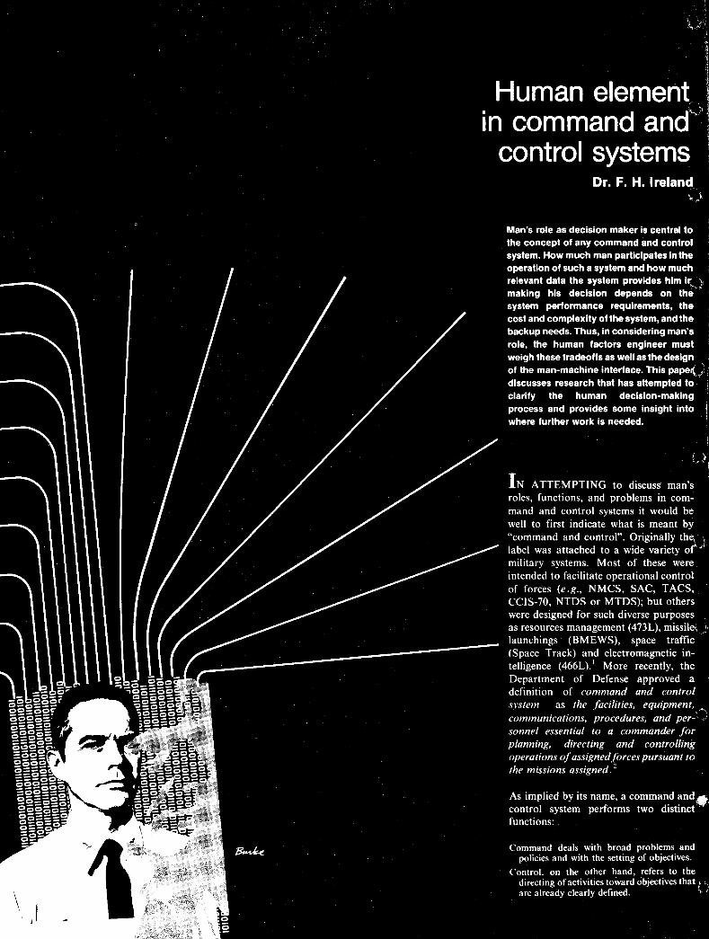
Human elem~nt in command and control systems Dr. F. H. Ireland 8
Remotely piloted vehicles-command and control D. Shore 13
Managing computer pro£lram development Dr. S. A. Steele I R. A. Dupelll A. M. Fleishman I E. T. Hatcher 14
Computer program reliability Dr. P. G. Anderson I L. H. Crandon 18
Impact of hardware/software tradeoffs in command and control systems J. C. Kulp 24
Computer selection for command and control systems H. J. Hurtado I Dr. S. A. Steele 28
Software verification and validation for command and control systems
Simulation of a command and control data processing and display system
AEGIS engineering model command and control system
Command and data handling subsystem for Atmosphere Explorer
A. R. Chandler 32
C. S. Warren 36
F. Bernstein I J. Strip 43
W. V. Fuldner 50
Performance monitoring and fault diagnostics of command and control systems T. Taylor I M. LeVarn I J. O'Connell 56
The use of computer-aided design in the manufacturing of welded-wire circuit boards M. A. Eastwood I A. S. Baran 63
Self-calibration of land-based pulsed radar from satellite track
Videovoice-'a review
Simplifying microcomputer architecture
Recent developments in photomultipliers for liquid scintillation counting
Pen and Podium
Dates and Deadlines
Patents Granted
News and Highlights
IEEE Fellows
J. J. O'Connor I R. R. Rowe 68
S. N. Friedman 72
J. Weisbecker 77
D. E. Persyk I T. T. Lewis 82
85
89
90
91
96
ed .. I
If you think the title of this "editorial input" excludes you, you're wrong.
Each year, RCA engineers and scientists put their names to about 2500 formal documents, including published papers and presentations, reports, and patent disclosures. This amounts to more than one document each year for every two engineers. Add in the plethora of "everyday" writing-memos, letters, proposal and report inputs, engineering notebooks-and the number could easily double.
The statistic is at once encouraging and disturbing. On the one hand, 2500 formal documents is an impressive output. Yet, one has only to glance at several RCA Engineer listings of published papers, presentations, and patents granted to see that a rather small percentage of the engineers and scientists produce most of these published documents.
But this imbalance makes sense: for some members of the RCA technical staff, the technical report or paper is the product. In product design and development areas, however, primary emphasis is, rightfully, on the hardware. Before the first unit is designed, built, and shipped, the next five are needed, and there is little time to document any of the solid, often ingenious, engineering work that is the backbone of every successful product line.
There is no easy solution to the problem, except to ask busy engineers to become busier and to offer some time-saving techniques.
Unfortunately, most formal courses in technical writing (and most books about the subject) tend to overemphasize grammar, style, and elegance of expression, almost to the
I
• for authors only
exclusion of such important considerations as planning, organization, and content. Correct grammar and clear style are important, but they often become unnecessary psychological obstacles to getting a paper written.
There are many places an engineer can find help with these details after his first draft is complete: Senior engineers or managers who have done it before; engineering editors or writers who do it every day; or coworkers who may simply be able to read a paper with a fresh outlook.
The really important part of the writing process-producing a complete first draft-can be done only by the engineer. And there are ways to do it quickly.
Many writers waste time laboring over the introduction, title, section headings, and conclusions. Usually it is better to work from the "inside out"-to write the detailed text first; the words for the title and introduction will spring from this effort.
Another time-saver is to make use of the vast quantities of material hidden in drawers and files already in the form of status reports, memos, and notebook entries. Still another sou rce may be proposals, contract reports, or instruction manuals.
Yet another aid in getting a paper done is to discuss the topic with coworkers; often such two-way communication will help the author organize his effort.
The primary ingredient, however, is self-confidence. The engineer is the final authority; few other professionals are trained to think as logically or organize as well as engineers. They are-by training and tempera-
•
ment, if not always by chOice-good writers. Their work is sought, read, and used by their colleagues in the profession, and by other RCA business professionals in management, sales, marketing, advertising,_ and purchasing. The engineer's writing is the message that will ultimately reach, and influence, the customer.
In this business, the important communications start with theengineer-all it takes is for the engineer to start.
-J.C.P.
----------------------Future issues
The next issue of the RCA Engineer features research, deSign, and product development at RCA Limited in Canada. Some of the topics to be. covered are:
Electro-optics
Acoustic surface-wave filters
Numerical control
Broadcast video equipment
Consumer electronics
Antenna design
Communications eqUipment
•
Discussions of the following themes. are planned for future issues:
International activities
Consumer electronics
Automatic testing
Parts and accessories
SelectaVision
Videovoice
Advanced communications
Electro-optics
•
•
• Command, control, and ~ommunications - an introduction
D. Shore
_ast issues of the RCA Engineer have treated the technology associated with military command, control, and communications - or as it is normally abbreviated, C'. We have felt that these articles covering data processing, software, displays and communications needed a systems overview. This issue of the RCA Engineer is the result.
• COMMAND, control, and com-munications is, indeed, a systems area of great interest to RCA engineers and to the Corporation. First, it is an extremely large business area (see Table I) which
.~Iosely matches our corporate abilities. Second, military C1 systems and technologies have become the precursor of civilian communication and control systems and hardware - another major RCA business area. Communication satellites, automatic switching and
.heckout, operator consoles and displays, and the latest handheld or mobile radios are typical examples of this technology synergism. Finally, it is an area that appeals to the creative engineer for the technical challenges it offers and
.he opportunity to contribute to ~eaningful progress in our national
security and economic and social welfare.
Military C l in all its forms is so complex and diversified, encompassing so many technical areas, that it takes multi-
liOlume reports to describe all of its ramifications. This brief overview
•
attempts to summarize what it is all about, how the US military C l system is organized, some of the problems it is grappling with, and to point out technology areas where continued progress will lead to further gains in effectiveness. Subsequent papers in this issue will deal with specific C l system elements and technologies.
Because there is an oversupply of C l
definitions, it is advisable to agree on this matter before proceeding further. Without arguing the merits of the many definitions offered in the past by individuals and agencies,l it is probably safest to choose the following latest definitions issued by our highest military authority as follows: 2
"command and control system - The facilities, equipment, communications, procedures, and personnel essential- to a commander for planning, directing, and controlling operations of assigned .forces pursuant to the missions assigned."
"communications - A method or means of
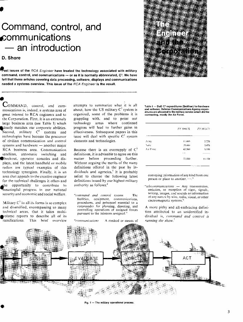
Fig. 1 - The military operational process .
Table I - DoD C' expendilures ($million) for hardware and software. Defense Communications Agency expen~ dilures are allocated to the military servi¢e which did the contracting, mostly the Air Force.
Army
\i\\.'Y
Air Force
FY 1946-72
11,000
19,000
43,500
FY 1973·77
2,720
3,470
5,530
73,500 11,720
conveying information of any kind from one person or place to another, , ","
"telecommunications - Any transmission, emission, or reception of signs, signals, writing, images, and sounds or information of any nature by wire, radio, visual, or other electromagnetic systems,"
A more pithy and all-embracing definition attributed to an unidentified individual is, command and control is running the show. l
3
4
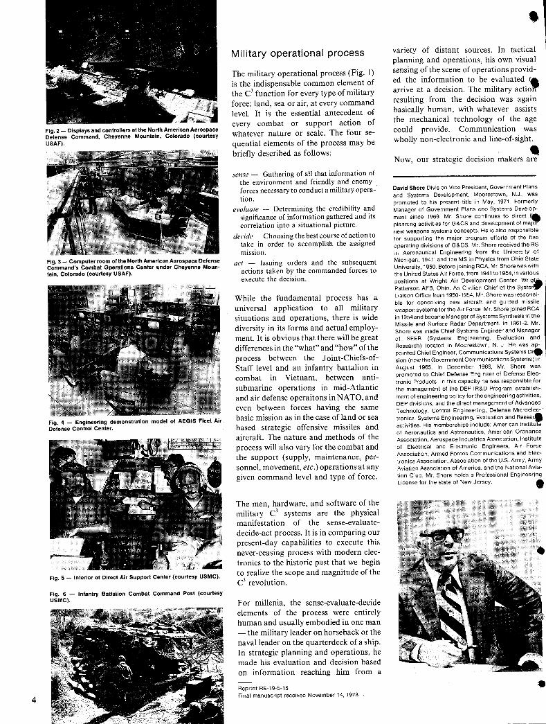
Fig. 2 - Displays and controllers at the North American Aerospace Defense Command, Cheyenne Mountain, Colorado (courtesy USAF).
Fig. 3 - Computer room of the North American Aerospace Defense Command's Combat Operations Center under Cheyenne Mountain, Colorado (courtesy USAF).
Fig. 4 - Engineering demonstration model of AEGIS Fleet Air Defense Control Center.
Fig. 5 - Interior of Direct Air Support Center (courtesy USMC).
Fig. 6 - Infantry Battalion Combat Command Post (courtesy USMC).
Military operational process
The military operational process (Fig. I) is the indispensable common element of the C3 function for every type of military force: land, sea or air, at every command level. It is the essential antecedent of every combat or support action of whatever nature or scale. The four sequential elements of the process may be briefly described as follows:
sense - Gathering of all that information of the environment and friendly and enemy forces necessary to conduct a military operation.
evaluate - Determining the credibility and significance of information gathered and its correlation irto a situational picture.
decide - Choosing the best course of action to take in order to accomplish the assigned mission.
act - Issuing orders and the subsequent actions taken by the commanded forces to execute the decision.
While the fundamental process has a universal application to all military situations and operations, there is wide diversity in its forms and actual employment. It is obvious that there will be great differences in the "what" and "how" of the process between the J oint-Chiefs-ofStaff level and an infantry battalion in combat in Vietnam, between antisubmarine operations in mid-Atlantic and air defense operaitons in NATO, and even between forces having the same basic mission as in the case of land or sea based strategic offensive missiles and aircraft. The nature and methods of the process will also vary for the combat and the support (supply, maintenance, personnel, movement, etc.) operations at any given command level and type of force.
The men, hardware, and software of the military C3 systems are the physical manifestation of the sense-evaluatedecide-act process. It is in comparing our present-day capabilities to execute this never-ceasing process with modern electronics to the historic past that we begin to realize the scope and magnitude of the C3 revolution.
For millenia, the sense-evaluate-decide elements of the process were entirely human and usually embodied in one man - the military leader on horseback or the naval leader on the quarterdeck of a ship. In strategic planning and operations, he made his evaluation and decision based on information reaching him from a
Reprint RE-19-5-15 Final manuscript received November 14. 1973.
variety of distant sources. In tactical planning and operations, his own visual sensing of the scene of operations provided the information to be evaluated ta arrive at a decision. The military actio1/" resulting from the decision was again basically human, with whatever assists the mechanical technology of the age could provide. Communication was wholly non-electronic and line-of-sight.
N . d .. • ow, our strategic eClSlOn makers are
David Shore Division Vice President, Government Plans and Systems Development, Moorestown, N.J., was promoted to his present title in May, 1971. Formerly Manager of Government Plans and Systems Development since 1969, Mr. Shore continues to direct t. planning activities for G&CS and development of major new weapons systems concepts. He is also responsible for supporting the major program efforts of the five operating divisions of G&CS. Mr. Shore received the BS in Aeronautical Engineering from the University of Michigan, 1941; and the MS in Physics from Ohio State University, 1950. Before joining RCA, Mr. Shore was with the United States Air Force, from 1941 to 1954, invarious positions at Wright Air Development Center, Wrig'A Patterson AFB, Ohio. As Civilian Chief of the Systen" Liaison Office from 1950-1954, Mr. Shore was responsible for conceiving new aircraft and guided missile weapon systems forthe Air Force. Mr. Shore joined RCA in 1954 and became Manager of Systems Synthesis in the Missile and Surface Radar Department. In 1961-2, Mr. Shore was made Chief Systems Engineer and Manager of SEER (Systems Engineering, Evaluation and Research) located in Moorestown, N. J. He was appointed Chief Engineer, Communications Systems Di. sian (now the Government Communications Systems) in August 1965. In December 1966, Mr. Shore was promoted to Chief Defense Engineer of Defense Electronic Products. In this capacity he was responsible for the management of the DEP IR&D Program, establishment of engineering policy fortheengineering activities, DEP divisions, and the direct management of Advanced Technology, Central Engineering, Defense Microelectronics, Systems Engineering, Evaluation and Resear. activities. His memberships include: American Institute of Aeronautics and Astronautics, American Ordnance Association, Aerospace Industries Association, Institute of Electrical and Electronic Engineers, Air Force Association, Armed Forces Communications and Electronics Association, Association of the U.S. Army, Army Aviation Association of America. and the National Aviation Club. Mr. Shore holds a Professional Engineering License for the state of New Jersey. •
•
•
• WORLOWI DE
MI LITARY COMMAND & CONTROL SYSTEM
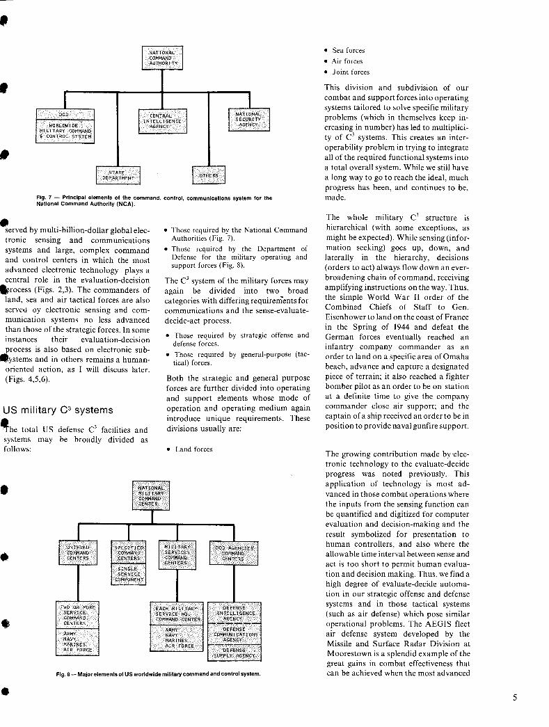
Fig .. 7 - Principal elements of the command, control, communications system for the National Command Authority (NCA).
flerved by multi-billion-dollar global electronic sensing and communications systems and large, complex command and control centers in which the most advanced electronic technology plays a central role in the evaluation-decision
.rocess (Figs. 2,3). The commanders of land, sea and air tactical forces are also served oy electronic sensing and communication systems no less advanced than those of the strategic forces. In some instances their evaluation-decision process is also based on electronic sub-
.ystems and in others remains a humanoriented action, as I will discuss later. (Figs. 4,5,6).
US military C3 systems
~he total us defense C3 facilities and systems may be broadly divided as follows:
• NATiONAL MILITARY COMMAND CENTER
I I
I UNIFIED SPECIFIED COMMAND COMMAND CENTERS CENTERS • SINGLE
SERVI CE COMPONENT
• Those required by the National Cl'lmmand Authorities (Fig. 7).
• Those required by the Department of Defense for the military operating and support forces (Fig. 8).
The C3 system of the military forces may again be divided into two broad categories with differing requirements for communications and the sense-evaluatedecide-act process.
• Those required by strategic offense and defense forces.
• Those required by general-purpose (tactical) forces.
Both the strategic and general purpose forces are further divided into operating and support elements whose mode of operation and operating medium again introduce unique requirements. These divisions usually are:
• Land forces
MILl TAllY I DOD AGENCIES I SERVICES COMMAND COMMAND CENTERS CENTERS
TWO OR MORE EACH MILITARY OEFENSE SERVICE SERVICE HQ. INTELLI GENCE COMMAND COMMAND CENTER AGENCY CENTERS 1-------
ARMY DEFENSE • ARMY NAVY COMMUNI CATIONS NAVY MARINES AGENCY MARINES AIR FORCE f------AIR FORCE DEFENSE
SUPPLY AGENCY
Fig. 8 - Major elements of US worldwide military command and control system.
•
• Sea forces
• Air forces
• Joint forces
This division and subdivision of our combat and support forces into operating systems tailored to solve specific military problems (which in themselves keep increasing in number) has led to multiplicity of C1 systems. This creates an interoperability problem in trying to integrate all of the req uired functional systems into a total overall system. While we still have a long way to go to reach the ideal, much progress has been, and continues to be, made.
The whole military C1 structure is hierarchical (with some exceptions, as might be expected). While sensing (information seeking) goes up, down, and laterally in the hierarchy, decisions (orders to act) always flow down an everbroadening chain of command, receiving amplifying instructions on the way. Thus, the simple World War II order of the Combined Chiefs of Staff to Gen. Eisenhower to land on the coast of France in the S pring of 1944 and defeat the German forces eventually reached an infantry company commander as an order to land on a specific area of Omaha beach, advance and capture a designated piece of terrain; it also reached a fighter bomber pilot as an order to be on station at a definite time to give the company commander close air support; and the captain of a ship received an order to be in position to provide naval gunfire support.
The growing contribution made byelectronic technology to the evaluate-decide progress was noted previously. This application of technology is most advanced in those combat operations where the inputs from the sensing function can be quantified and digitized for computer evaluation and decision-making and the result symbolized for presentation to human controllers, and also where the allowable time interval between sense and act is too short to permit human evaluation and decision making. Thus, we find a high degree of evaluate-decide automation in our strategic offense and defense systems and in those tactical systems (such as air defense) which pose similar operational problems. The AEGIS fleet air defense system developed by the Missile and Surface Radar Division at Moorestown is a splendid example of the great gains in combat effectiveness that can be achieved when the most advanced
5
6
electronic technology is applied with skill and ingenuity to automation of the senseevaluate-decide-act process.
Support operations have also proven amenable to a process automation because numbers are the essence of this function: quantities of people or things needed or on hand, weight and size, consumption rates, transportation modes, capacity and speed, locations and 'distances, time to service, repair, load, etc. Consequently, this was an early field for C1 automation and one in which continuing refinements are still being made.
Likewise, automation of both military and civil telecommunications has made significant progress utilizing the increasing bandwidth available from the use of higher frequencies and satellites.
In some areas of general-purpose-forces (limited warfare) operations, most notably land combat, there has been little progress in developing C1 systems comparable in task execution and performance to those now employed by strategic forces. While the past decade has seen great progress in this area in the development and use of electronic devices for sensing and communications, the evaluate and decide process present problems for which a solution is yet to be found.
There are a number of reasons why we have failed thus far to automate the land combat evaluate-decide process satisfactorily. One fundamental reason is the nature of the problem as stated below:
"When the game he (the commander) is playing is continually subject to unpredictable change, there is simply no information technology that can be called upon to cast the commander's problem in the form of a set of binary choices.
"The crux of the matter is that our commanders-and, derivatively their information systems-must deal with contingencies. Each contingency is a choice-point, and the possible paths ahead at any moment ramify so rapidly that detailed pre-planning that is adjusted to contingent events is literally impossible." 4
This inability to define with precision the problem to be solved leads to a computational requirement of the awesome magnitude described below:
"Dr. Nicholas Smith of the Research Analysis Corporation, in his pamphlet
'Operations Research in the Next Twenty Years: A Technological Forecast' (1964), estimated that the large number of variables-men, weapons, enemy, terrain, and weather-involved in the actions of a battalion-size unit in the attack would require 10500 computations to determine the best tactic by examining the effect of all possible combinations of factors. This number is one trillion mUltiplied by itself over 41 times. Even after discounting the irrelevant and trivial possibilities, the number of conceivable combinations, remains unmanageably large.'"
At best, C1 can provide this tactical commander with the latest data, in the clearest form, at his greatest convenience. The total automated solution is not in sight.
A lively current issue in C1 system design, particularly in those systems intended for tactical forces, is whether they should be centralized or decentralized. At the beginning of the era of digitized automation of C1
, all systems were centralized, both by necessity and by inclination. The space required by the available general-purpose computers and their peripheral equipment and the controlled environment necessary for their operation called for large permanent installations. At the same time, there was the traditional desire of a commander to retain the greatest possible measure of control over all of his forces and their operations. Automation of C1 systems seemed to make this possible in a degree never before attained. The development of strategic C1 systems thus went forward rapidly because these two conditions were not contrary to any system requirement.
Tactical C1 lagged strategic C1 because mobility was e.ssential. As technology reduced the size of command and control elements, tactical C1 began to evolve. The aforementioned multiparametric problems forced the solutions into specific categories of operations such as fire control.
Full dependence on a central tactical C1
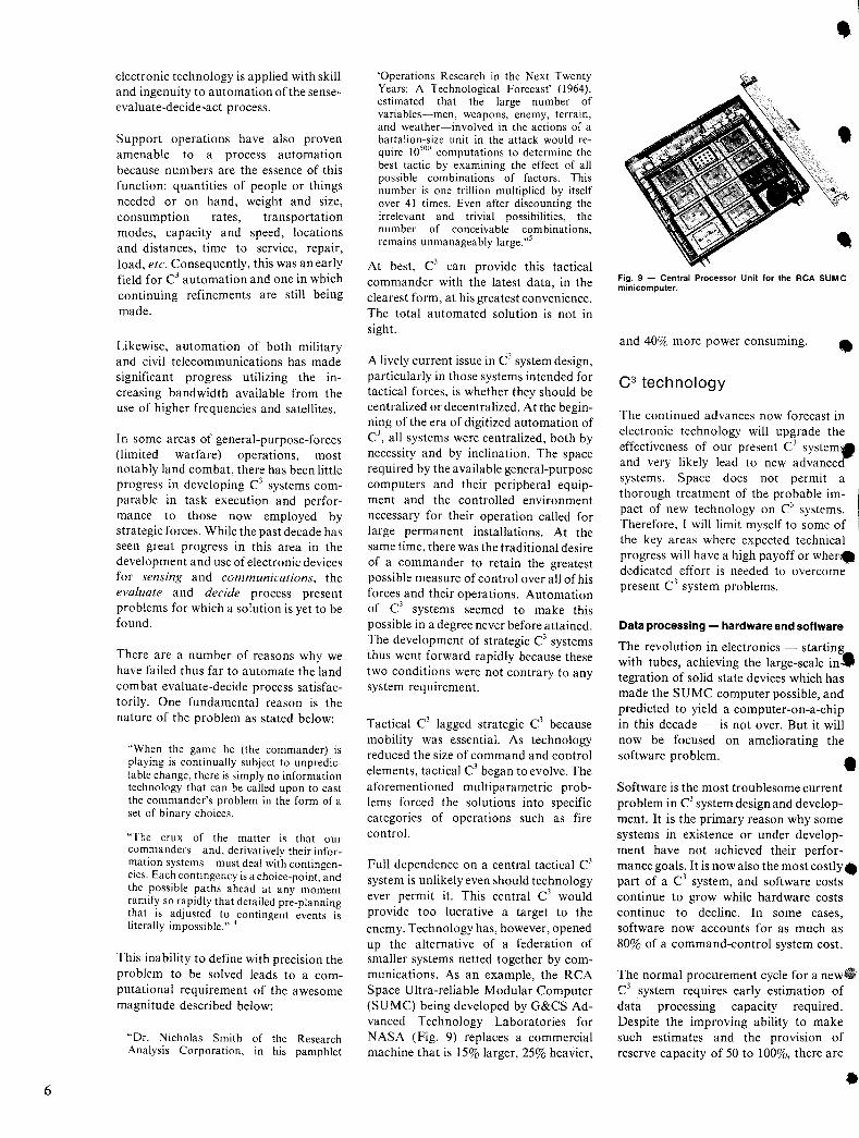
system is unlikely even should technology ever permit it. This central C1 would provide too lucrative a target to the enemy. Technology has, however, opened up the alternative of a federation of smaller systems netted together by communications. As an example, the RCA Space Ultra-reliable Modular Computer (SUMC) being developed by G&CS Advanced Technology Laboratories for NASA (Fig. 9) replaces a commercial machine that is 15% larger, 25% heavier,
Fig. 9 - Central Processor Unit for the RCA SUMC minicomputer.
and 40% more power consuming. •
C3 tech nology
The continued advances now forecast in electronic technology will upgrade the effectiveness of our present c1 system. and very likely lead to new advanced systems. Space does not permit a thorough treatment of the probable impact of new technology on c1 systems. Therefore, I will limit myself to some of the key areas where expected technical progress will have a high payoff or wher. dedicated effort is needed to overcome present C1 system problems.
Data processing - hardware and software
The revolution in electronics - starting with tubes, achieving the large-scale in. tegration of solid state devices which has made the SUMC computer possible, and predicted to yield a computer-on-a-chip in this decade - is not over. But it will now be focused on ameliorating the software problem. • Software is the most troublesome current problem in C1 system design and development. It is the primary reason why some systems in existence or under development have not achieved their performance goals. It is now also the most costly. part of a C l system, and software costs continue to grow while hardware costs continue to decline. In some cases, software now accounts for as much as 80% of a command-control system cost.
The normal procurement cycle for a new. Cl system requires early estimation of data processing capacity required. Despite the improving ability to make such estimates and the provision of reserve capacity of 50 to 100%, there are
•
, an astonishing number of instances where the computer procured is found inadequate when the software is finally
.s:Ieveloped. This has caused expensive "'reprogramming to utilize the computer
most efficiently, adding mainframe and memory capacity, and/ or adding a separate system to share the load.
Much research is under way to cope with _he software dilemma. (see several articles
appearing in this issue).9.10.11
A new viewpoint growing in the community is the idea of "software first". This means software is developed on a large,
*eneral purpose computer and then a C1
computer is selected or developed with good assurance its capacity will be adequate. Software can be translated through a higher order language in the case of an existing computer. With the rapid evolution of design automation and
.arge-scale integrated circuits, it is also possible to develop a C1 computer organized to use the software directlyyet at a reasonable cost and schedule.
Technology is also expected to relieve the software problem. First, mini- or micro-
.omputers will perform parts of the C3
function; software then can be broken down into a number of smaller, more manageable units. Second, very large solid-state memories will be made economical by LSI technology. This permits compartmenting the memory into
_different program elements and easier programming.
The commander, today, is fairly remote from the software problem. Worse, he feels isolated from his automated system
.because programmers handle all software. The future may eventually see the commander able to address his system by voice and personally control its actions.
~ommunications
The last "C" in C3 is communications. Without it the commander, of course, cannot command. The human runners employed by the ancients are largely replaced by electromagnetic messengers
ecovering a frequency domain from a few hertz to light. As the bandwidth demands rose to permit computer-to-computer communications, there has fortunately evolved satellite systems which will eventually provide global, wide band services.
•
Military C3 communications make use of every other applicable civil system as well. However, the military must strive for security against enemy snooping or disruption. A number of dedicated, secure modes have been developed for this purpose. It is in the never-ending game of measure VS. countermeasure that technology challenges remain. Frequency allocations are difficult to obtain because 6f the many demands on the total spectrum from a host of international claimants. As a result, frequencies in the K-band and above are being opened. These are less desirable for tactical C3 use because of weather attenuation.
It should be mentioned that voice communications are still needed. Most commanders derive important situational clues by listening to how their subordinates sound in their verbal reports. 6
Analog-to-digital conversion
Continued progress in improving the speed and accuracy of all elements and functions of military C3 systems will require greater use of digital transfer, processing, and storage of information. Ways must be found to do this without filtering out the intangible, intuitive, conceptual, human content of some information - as these inputs frequently may be of the highest importance in making a decision, particularly in tactical forces. 7
One author comments on this problem:
"We have spent billions of dollars increasing the number of channels, speeding the bitrates, adding memory capacity, and improving the signal-to-noise ratio; but we have paid scant attention to the problem of how we are transferring meaning from one mind to another." ,
Displays
The displays in C1 fall into two categories: small for individuals, and large displays for groups.
The individual displays are normally tv consoles with black-and-white being replaced by color. Computer-driven displays are now capable of showing video images, graphics, and/ or alphanumeric information.
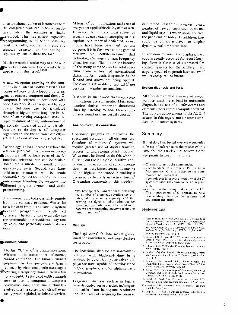
Large-scale displays, such as in Fig. 2, have depended on projection techniques and suffer from inadequate resolution and light intensity requiring the room to
be dimmed. Research is progressing on a number of new concepts such as plasma and liquid crystals which should correct the problems of today. In addition, they could be computer-driven to display dynamic, real-time situations.
In addition to voice and displays, hard copy is usually prepared for record keeping. Even in the case of automated fire control systems for the artillery, hard copy is specified to permit later review of results compared to intent.
System diagnosis and tests
All C1 systems of whatever size, nature, or purpose must have built-in automatic diagnosis and test of all subsystems and elements under central computer control. The notable achievements of the AEGIS system in this regard must become standard in all future systems.
Summary
Hopefully, this broad overview provides a frame of reference to the reader of this issue for the articles that follow. Some key points to keep in mind are:
_c1 exists to assist the commander. -Commanders vary from a Patton to a
Montgomery. C1 must adapt to the commander, not vice-versa.
-Technology is improving the ability of the C1
system to assist the commander, not replace him.
·-Software is the pacing, riskiest part of C3
-The improvement of C1 appears to be a never-ending challenge to systems and equipment designers.
References
J. Parsons, H. M.~ Perry, W .E.; "Concepts for Command and Control Systems," Systems Development Corporation for Office of Naval Research. AD 479365. (Dec. 23. 1965).
2. rhe loint Chiefs of Staff, D;clionan' q( United Srall's Military Termsj()r joint Usage. JCS P'ub I. (.Ian. 3. 1972).
J. Parsons and Perry. op. cif. p73.
4. Christie, LS.: Kroger, M.G.; "Command and Control in Limited War," Proceedings. 'Ith Military Operations Research Society Symposium, (1963) p212.
S. Hillman, R.G., "A World of Changing Systems", Military Review (Dec. 1971) p44.
6. Paschall, Maj. Gen. Lee M.: "USAF Command, Control and Communications Priorities", Signal magazine (Nov. 1973) p12.
7. Genestry, S.M.: WesseL A.E.; "Some Thoughts on Developing Future Command and Control Systems," The RAND Corp .. AD 607 938. (Oct. 1964).
X. Belden, T.G. ; The LanKuage oj" Cummand, Studies of Command and Control, Study No.2 Institute for Defense Analysi~. AD 425 822 (Aug. 1962).
l). Dupell, R.; Steel, S.A.: Fleishman, A.: Hatcher, LT.: "Managing computer program development," this issul'.
10. Crandon, L.H.: Anderson, P.G.; "Computer program reliability" this issue.
r I. Kuip, J.e.; "Impact of hardware.·software trade-ofrs ina command and control system, "this issue .
7
\ I _ j
, The command function predominates in the systems intended for the h' h '1' Ig er ml Itary. echelons; at lower levels the
• emphasIs tends to shift more toward
, control.
Automation and the changing role of the human operator
-A . utomatlOn has had a considerable im-pact on command and control systems and has led to changes in the roles played by t~e human operators. The effects are par.tlcularly pronounced in systems in ~hlch the control functions are empha-
.. sized. In these systems, automated equip-
Dr. Fred H. Ireland, Mgr .. I nformation Systems and .. Human Facto~s, Systems Development, Government 1"'i and Commercial Systems. Camden, N.J., received the
. BS (1948), MA (1949) and PhD (1955) in Experimental ~SYChOI09y from Fordham University. From 1950to 1952
e was Senlo~ Re~earCh Associate with the human factors consulting firm of Dunlap and Associates where he worked .on the Terrier Land Based Fire Control ~ystem, vanous mobile radar units and on a subma( fire control project. He then spent two years a~n: Research Psychologist with the N.Y. State Psychiatric
• Institute. In 1955 he joined RCA A M . s anager of the M,oorestown Human Factors Engineering activity he directed the human engineering efforts for TALOS for the Atlas Launch Control and Checkout System and for BMEWS. He also held an appointment of human factors consultant with the HQ, USAF Directorate of InstallatIOns. For an eighteen month period starting early In 1962, he held the position of Assistant Director for InformatIOn and Control Systems and Human Facto .
• NASA's Office of Manned Space Flight. He rejoined ~~'~ ~ In 1963 and is manager of Information Systems and
Human Factors in G&CS's Systems Development (SO) activity. He holds membership in IEEE APA d S· Xi. ' ,an Igma
Reprint RE-19-5-14 Final manuscript received January 14, 1974
•
ment has largely taken over such previously human activities as target detection, acquisition, correlation, tracking, identification, threat evaluation, intercept prediction, weapons assignment, and guidance.
The basic command function, on the other hand, is still exercised by a human commander, who is responsible for the final decisions. He, in turn, is supported by other men who form his staff and are responsible for I) Acquiring information on the status dis
position and actions of their own and h~stile forces, on logistics, on weather, and on the operability and availability of weapons and communication facilities;
2) Evaluating, analyzing and interpreting the mformation in terms of assigned missions and objectives;
3) Developing hypotheses about enemy intent, plannmg response alternatives and estimating attendant effects and c~sts; and
4) Submitting action recommendations to the commander for his decision.
In some of these activities the members can be, and have 'been, ported by automated equipment.
staff sup-
In fact, automation of the information acquisition, manipulation, storage, and retrieval processes has already made considerable inroads at the higher command levels where data processing equipment and automated displays are noW in common use. Furthermore, due to the rapid development of large-scale integrated circuitry-and the concommitant reductions in size, weight, and powerminiature general-purpose battlefield computers can now be packaged together with keyboards, hardcopy printers, and "soft copy" displays in suitcase-size containers. When connected to automatic data links, these devices can process messages automatically and their computational capabilities make them useful for the solution of operations control problems. It appears quite possible that such units, augmented with external memory, could be used for the processing of large amounts of intelligence data to support command decision-making in the ~ield. Someday we may even see such eqUipment playing a more direct role in the formulation of higher-level decisions.
~utomation of such systems does not Imply that all human operators can be eli~inated nor even that manpower reqUirements have been reduced. It does, however, usually change the roles that
such operators play. Previously, operators may have been used to communicate, record, file, or retrieve information and manually post data on displays; in an automated system, they may direct the utilization of equipment, monitor its performance, and assess its data quality. And, of course, men will be needed to maintain and repair the automatic gear and also to revise and update the system software.
Human factors engineering in C2 systems design
Human factors engineers participate initially in deciding which system functions ought to be assigned to man and which to the machine. Such decisions must be based, at least in part, on the relative
capabilities of the two.
Humans are particularly adept at perceiving patterns and at generalizing from them. They can detect signals in very noisy environments. They can improvise and adopt flexible procedures to handle low-probability events. They can profit from experience, reason inductively, and generate new and different solutions to problems; and they are unique in being able to exercise judgement.
Machines, on the other hand, are sensitive to many stimuli that man is unable to perceive; they can respond more quickly to control signals; and they are not plagued by boredom or fatigue when performing routine, repetitive tasks. They can store and recall incredibly large amounts of data and perform complex computations rapidly and with perfect accuracy. The intriguing question of whether, and to what extent, a machine could or should eventually participate in formulating command decisions has often been debated. Some of the relevant experimental work which has been done to date will be described later.
cost tradeoffs
Economic considerations also enter into the man-machine choice. If the performance of a function, which could be accomplished by either a man or a piece of equipment, were to represent a fulltime job for a man, it might well require a four- or five-man complement for around-the-clock manning. The recruiting, training, and maintenance
9
10
costs for such manpower is not trivial. On the other hand, if a function which could be performed either by man or machine, can be assigned to a man already in the system without overloading that man, it may be desirable to forego automation of that function.
System back-up
The capability of a system to sustain equipment damage or malfunction and still be able to function, albeit with reduced effectiveness, is another important consideration when determining the desirable degree of automation. So-called graceful degradation can often only be accomplished by using men to back up the automatic operation. To be instantly useful and effective in emergencies, these men must not only be available on a standby basis, they must also be given all the up-to-the-minute data needed to assume the operational responsibilities. Further, since time for a "cold start" is usually not available, the operators must monitor the system while it is operating in the automatic mode. Maintaining the proficiency and morale of back-up personnel-who may only rarely, if ever, be called upon to perform operationally-is a challenging and frequently frustrating human factors problem.
Interface design
Equipment designers are interested in an early assessment of the numbers and, types of operating positions in the system because each operator usually requires a console or other man-machine interface equipment. Therefore, once the human functions have been defined, it is necessary to determine the number and types of operators needed to carry them out. Computer-based simulation programs have been developed to help human factors specialists gauge anticipated operator workloads and manpower requirements. In some cases, several logically or procedurally related human functions can be allocated to a single operator. In other cases, it may take several operators, working in parallel, to carry the workload imposed by a single system function.
Defining information requirements
The next problem is to determine exactly
what information each operator needs to perform his tasks. The data needed for control purposes is much easier to define than that for command. After all, the thing to be controlled (such as a radar antenna, an aircraft or an infantry batallion) is clearly defined as is the objective to be attained. Information needed for control can be fairly accurately determined by a detailed task analysis. During that process, each human function is broken down into sequences of discrete task elements. The information items needed for each element are then specified as are the action requirements.
It is questionable whether this analytic approach can be used successfully to determine inf~rmation needs for command decisions as well. At first thought, it seems relatively simple to outline the range of decisions that a commander must make and then to determine the minimum set of information items required for these decisions. However, in the typical strategic or tactical command situation, the objective is usually not clearly defined. There is often considerable uncertainty concerning the significance of data, the intent of the enemy, or the likely cost and effectiveness of various action options. The real difficulty in defining information needs for command decisions stems from the fact that the human decision-making process is still very poorly understood.
Although this process is yet a mystery, we do know that good decisions require reliable, relevant and up-to-date information; lacking such information, a commander might just as well flip a coin. What information should we then provide for a commander? If we simply ask him what information he thinks desirable he will probably answer something like "all of it". What he really means is that he cannot say beforehand what data he will want in order to evaluate a new threat, and that he would rather be faced with the problem of having to filter the irrelevant data than to chance the possibility of its insufficiency.
Results of experimental work
Suppose it were possible somehow to determine all information items relevant to a decision, as we can more or less do in an experimental situation. Would it really be beneficial to present all of them to the
, decision maker? This question was investigated by Hayes3 in 1962. He found that as the number of relevant information items increased, the time required to make a decision also increased, but the_ quality of the decision did not improve. Furthermore, when the time available for making the decisions was held constant, the decisions actually deteriorated as more and more relevant information was supplied. Thus, it would appear that too. much information, even if it is of the right . kind, can be a bad thing. However, if it was really the quantity of information that created the problem for the decision makers in the Hayes experiment, predigesting and summarizing the data prior to display should improve matters .•
The merits of this approach were investigated in 1964 by Merifield and Erickson.4
•s
,6 In their experiments, the decision-making subjects were required to discover an enemy's strategy underlying his missile ~~tacks on various ci~ies .• After several cItIes were reported hit, a . subject was asked to judge which of his nation's resources the enemy was attempting to destroy and to predict which cities would be attacked next. Before any attacks occurred, the subjects studied a large data matrix showing the. values of fourteen different resources located at each of forty-nine cities. One group of subjects also had access to a display which presented computergenerated statistical summaries of the information which were based on correla- .. tion, factor analysis, groupings and 'III\' variance ratios, which another group did not. As one might suspect, the group aided by the statistical summary outperformed the other.
To really find out what information a • commander needs in the field, it may be necessary to observe his decision-making process-at least under realistically simulated conditions such as during maneuvers-and have the commanders attempt to describe their procedure in detail. Despite the fact that many. decision-makers find it difficult to verbalize the mental steps involved, such an introspective method applied to the few who can do so may yield more worthwhile data than analytic techniques or so-called objective behavioral studies. To the extent that the decision-making procedures educed in this fashion can be reduced to algorithmic form, they can be modeled and validated. Conceivably, they might find use as decision-making aids, perhaps in the form of recommended actions.
•
• Other human factors constraints
The remaining human factors tasks involved in designing a command and
-control system are essentially the same as for any man-machine system, and adequate techniques for accomplishing them exist. These tasks include design and specifications of
.1) Man-machine interface equipments such as the display and control panels and entire operator consoles;
2) Display formats;
3) Operations and maintenance area arrangements including consideration of operator environmental factors such as lighting, noise levels, and air conditioning;
.4) Operating procedures and special job aids; and
5) Training, exercising and proficiencyevaluation means.
To verify the designs and to discover possible shortcomings, human factors
• specialists should also playa key role in the system tests and evaluations.
User participation during system development
• The participation of the end-user is virtually essential during the development of a command and control system. The designers can gain an appreciation of the user's real needs and concerns, and the chances for ultimate user acceptance of the system are increased. , The human factors specialist can often precipitate or substantially enhance such user involvement in the design process by providing early mockups of proposed consoles and displays. To be useful design
• tools, mockups should be full-scale, arranged in an area that simulates, as closely as practical, the environment in which the equipments and operators will ultimately have to work. During the early stages of system design, inexpensive static mockups made of pressboard or similar
• material can be used. These can be fitted with artwork panels showing the layout of displays and controls. Such displays should show the proposed information content and format. Later, when design
•
approaches are better defined, more substantial mockups with front panel hardware should be substituted. At that stage, partial instrumentation of the mockups and dynamic simulation of dis-plays may prove valuable.
The mockup area should also contain up-
to-date system flow diagrams, artist concepts and scale models of equipment, a word-picture or a voice recording describing a typical operation and other audio visual material for briefing future users and other visitors. Such mockup and briefing facilities, if constantly updated, can also serve as a valuable catalyst for the integration of the many concurrent, but disparate in-house design efforts.
Research on human decisionmaking
Human decision-making was previously pointed out as a persistent problem area that has been surrounded by much confusion. The main reason for the confusion is that the term decision-making, though often used, is very poorly defined. It has been applied to behavior which ranges all the way from determining which of two buttons to press in response to a simple light stimulus to a highest level judgment on whether to engage the nation in a war.
In the command and control system context, it is useful to distinguish between decisions made for purposes of control and those involved in command. The process unc\.erlying the former is much better understood, and analytic methods are available for determining the decision-maker's information requirements. In fact, algorithms for control decisions can often be clearly enough defined to permit automation of the entire process. On the other hand, much less is known as yet about how a commander makes the higher-level decisions when confronted by considerable uncertainty about his information and the possible consequences of his acts.
Questions about the basic process involved in command decision-making are indeed among the most challenging faced by human factors investigators who have already devoted considerable effort to this area. For example, a team at Ohio State University7.8,9,10 spent several years on attempts to determine how human subjects made certain types of diagnostic decisions and to see whether computers might be used to aid or replace men for such purposes. A Bayesian decision model was used. For each of several potential tactics available to an enemy, the experimental subject was given probabilities attached to specific obser-
vable actions which an enemy might take in order to implement the tactics. Thus, for a pincer attack, the subject might be told the probability of enemy troop concentrations in certain areas, the probability that he would use tanks or observation planes, etc, The specific probabilities assigned to such observable actions were different for the various possible enemy tactics. The problem for the subject was to induce composite conditional probabilities for the various possible enemy tactics from the known conditional probabilities of the discrete enemy acts reported to him.
As might be expected, the results showed that men usually do not extract all of the information inherent in the data. Surprising, however, at least to this writer, was the fact that a computer only performed about 10% better than man in aggregating the various conditional probabilities. Furthermore, as the men became more accustomed to the somewhat foreign task and were able to check their estimates against those produced by the machine, their performance began to approach that of the automatic equipment.
An obvious problem with this approach is that, in a real-world situation, it would be very difficult to obtain the original conditional probabilities for observable enemy acts as a function of alternative tactics. It might be possible to derive some probabilities from historical data, but most of the input probabilities would have to be based on expert opinion.
Some have argued that threat evaluation does not really constitute decision making at all since it does not involve action selection. In any event it is clear that command decision-making involves considerably more than merely the diagnosis of a situation.
Many other experiments have, in fact, been conducted in attempts to discover how commanders make decisions not only about the threat situation but also about their own tactics, the selection of weapons, the timing of countermoves, and conservation of their resources. Perhaps typical of these is a series of investigations begun in 1959 by the Operations Applications Laboratory of the Air Force Systems Command 11
,12,IJ at an annual cost of $250,000. In a simulated air defense environment, military subjects with prior air defense experience played the role of a commander who was
11
12
required to evaluate the threat posed by attacking aircraft or missiles and select appropriate defensive actions.
Among other things the experiments showed that
I) While subjects were able to devise successful strategies, they were generally unable to clearly verbalize them;
2) Their performance did not level off as expected with increased decision-making load (i. e., performance rate increased with load), and there was no clearcut breaking point at which performance suddenly deteriorated;
3) There was a tendency to use up and even squander available weapons when the supply appeared to exceed the demand; and
4) SUbjects changed about one half of the previously made decisions and often unwittingly those which they had made themselves.
But while investigations of this type undoubtedly have yielded interesting and useful information, none of these have, thus far, been able to provide any clear insight into the higher-level human decision-making processes involved in command.
An approach that may some day prove to be valuable is to provide the decision maker with a computerized simulation tool by means of which he can, in an accelerated time frame, test the probable effect of various potential courses of action before issuing his commands. The idea is similar to one for an automated aid to a chess player which would permit the latter to look several moves ahead, both with regard to his own as well as his opponent's possible actions. This is, of course, difficult enough to do for a chess game which represents a clearly defined artificial battlefield with rules that regulate the movement of each piece. Simulation of real battlefield situations, with far less rigorously circumscribed action potentials on either side, poses an enormously greater challenge.
Suppose a commander had a computer available which could automatically determine the appropriate counteractions at least for a limited set of threat situations. Would he accept and use such a device-would he, in effect, let it make decisions for him? A series of experiments which were initiated in 1962 by the Applied Physics Laboratory (APL) ofthe Johns Hopkins University and which lasted four years, attempted to answer this question. The setting was a simulated shipboard combat information center
(eIq and the task again was to counteract airborne enemy threats. Eighty-one naval officers, ranging in rank from captain to lieutenant participated as cOI'lmander subjects. In addition to the customary situation and status displays found in a eIe, the commander was provided with a display showing the computer-recommended actions. Although the subjects were never aware of the fact, no actual computing equipment was used. Instead, one of the experimenters, trained to work in accordance with computer program rules, simulated the computer and provided problem solutions which would have been produced by such equipment.
With regard to the "computer" solutions, a commander had two options:
I) By doing nothing he could accept the computer recommendation, in which case the recommended action would be executed automatically, or
2) He could reject the recommendation within a certain time period and substitute action commands based on his own judgment.
During and following each experimental run, qualitative data were gathered from subject remarks and personal observations of the experimenters. In general, the subjects considered the experiments themselves quite educational and felt that the experience would help them in their operational tasks. But, while the commander welcomed the idea of computer aiding, the experiments revealed a wide range of individual differences as to the extent they actually accepted the computer-generated tactical action recommendations. Manual override often occurred because a commander felt that he had too.little time to evaluate the recommendation. Nevertheless it appeared that a commander could comprehend and evaluate up to five computer recommendations within half a minute and that most officers approved of the manual override method adopted as opposed to the possibility of requiring a positive action in order to accept a recommendation. It was felt that the latter approach would let an indecisive officer delay action too long.
Need for further work
Obviously much research on decisionmaking remains to be done. In particular, human engineering requires a set of basic principles in this area on which to base its recommendations for specific command and control system designs. Approached
• as an engineering problem, development of some useful knowledge, at least with regard to command information presentations, should not require such extensive experimentation as that described above" For example, assuming that a commander will want to know the current status of his own resources as well as those of his enemy, how should that information be formatted on a display so that it can be easily assimilated? Shouid ila. be done graphically or in the mor~ conventional tabular fashion? If the graphic approach is taken, which data should be shown in the form of curves, which as bar-charts, or in some other pictorial manner? A cataloging of such engineering related questions an1a problem areas is needed so that the required research can be programmed effectively.
References • I. Parsons, H. M.; Perry, W .E.; "Concepts for Command and Control Systems", System Development Corporation Technical Memorandum, TM-WD-227/000/00 (Dec. 1965).
2. Dictionary of United States Army Terms, Army Regulation. AR 310-24. (March 1968).
3. Hayes, J.R., "Human Data Processing Limits in Decision Making", Electronic Systems Division report, ESD-TDR-62-48 (1962)
4. Merrifield, P.R., Erickson, E.B., "System Support fo,a Hypothesis Generation", System Development Corporation Technical Memorandum, TM-1939 (1964).
5. Merrifield, Erickson, "Target Analysis in the HEMP Context-the Transitional Experiment" Part One", System Development Corporation Technical Memorandum, TM-2030/000/00 (1964).
6. Merrifield, Erickson, "Target Analysis in the Hemp Context-the Transitional Experiment, Part Two", System Development Corporation Technical Memoran·. dum. TM-2030/001/00 (1964). ~
7. Southard. 1.F., Schum. D.A., Briggs, G.E.; "An Application of Bayes Theorem as a Hypothesis-Selection Aid in a Complex Information-Processing System; Aerospace Medical Research Laboratories Report, AMRL-TDR-64-51 (August 1964).
8. Schum, D.A., "Inferences on the Basis of Conditionally Nonindependent Data", Aerospace Medical Research Laboratories Report, AMRL-TR-65-161 (December I%~ •
9. Schum, D.A., "Research on Simulated Bayesian Information-Processing System;;, Aerospace Medical Research Laboratories Report, AMRL-TR-66-78 (March 1966).
10. Howell, W .c., "Some Principles for the Design of Division Systems-A Review of Six Years of Research on a Command-Control System Simulation, Aerospace Me~ical Research Laboratories Report, AMRL-TR-67-136 (Sept. 1967).
II. Connolly. D.W .• Fox, W.R .• McGoldrick. e.e., "Tactical. Decision Making: II. The Effects of Threatening Weapons Performance and Uncertainty in Information Displayed to the Decision Maker on Threat Evaluation and Action Selection", Electronic Systems Division Report: ESD-TR-61-45 (1961).
12. Connolly, W.W., McGoldrick, e.e.. Fox. W.R .• "Preliminary Summary Report; Tactical Decision Making: II. The Effects of Truck Load on Damage, Cost and Kills", Electronic Systems Division Report: ESD-TR-61- e<J
43 (1961). ,.
13. Fox, W.R., Vance, W.H., "Tactical Decision Making: I, Action Selection as a Function of Truck Load Threat Cumplexity, Reliable Data Presentation and Weapon Uncertainty", Electronic Systems Division Report, ESDTR-61-42 (1961)
14. Homes. R.M., Gebhard. J.W., ":rhe Computer's Role in Command Decisions", U. S. Naval Institute Proceedings, (Sept. 1966).
•
, Remotely piloted vehicles
• command and control D. Shore
The latest war in the Middle-East demonstrated the lethality of air defense against manned aircraft. At the time of this writing, the cost in lives and in aircraft are not known in detail,
• however, it is clear that these losses were significant. As a result, increased emphasis is being paid in this country to the utilization of the unmanned remotely piloted vehicle, or as it is more generally known, the RPV. This paper discusses some of the milestones of RPV development and highlights significant RCA work in progress. We plan to provide more information in future issues on the RPV and RCA's technical contribution to this challenging new field.
•
•
•
•
•
T he radio-controlled aircraft is not new; indeed, Hugo Gernsbeck in the Marchi April 1931 issue of TV News published an article on the use of radiocontrolled ,1Ircraft with a tv sensor in the nose for military purposes. At that time, both radio control and television were laboratory curiosities.
In World War II, war-weary 8-17 bombers equipped with RCA television and a radio relay were used in "kamikaze"-type, unmanned attacks by the U.S. Air Force against the heavily defended Helgoland fortifications of the Germans. In the post-World War II era, military developments were concentrated on guided missiles in which man par-
MULTI-MODE CONSOLE
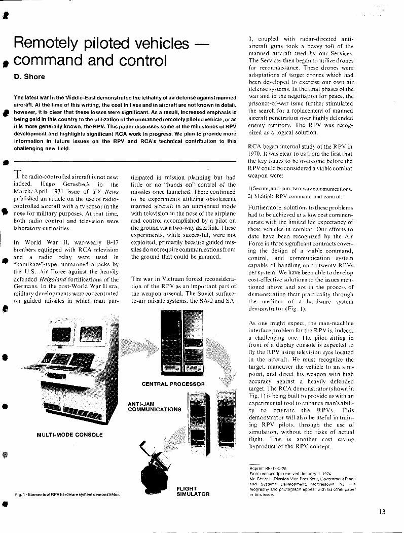
Fig. 1 - Elements of RPV hardware system demonstrator.
ticipated in miSSIOn planning but had little or no "hands on" control of the missiles once launched. There continued to be experiments utilizing obsolescent manned aircraft in an unmanned mode with television in the nose of the airplane and control accomplished by a pilot on the ground via a two-way data link. These experiments, while successful, were not exploited, primarily because guided missiles do not require communications from the ground that could be jammed.
The war in Vietnam forced reconsideration of the RPV as an important part of the weapon arsenal. The Soviet surfaceto-air missile systems, the SA-2 and SA-
CENTRAL PROCESSOR
ANTI-JAM COMMUNICATIONS
FLIGHT SIMULATOR
3, coupled with radar-directed antiaircraft guns took a heavy toll of the manned aircraft used by our Services. The Services then began to utilize drones for reconnaissance. These drones were adaptations of target drones which had been developed to exercise our own air defense systems. In the final phases of the war and in the negotiation for peace, the prisoner-of-war issue further stimulated the search for a replacement of manned aircraft penetration over highly defended enemy territory. The RPV was recognized as a logical solution.
RCA began internal study of the RPV in 1970. It was clear to us from the first that the key issues to be overcome before the R PV could be considered a viable combat weapon were:
i) Secure. anti-jam. two-way communications.
2) M ultipie R PV command and control.
Furthermore, solutions to these pro blems had to be achieved at a low cost commensurate with the limited life expectancy of these vehicles in combat. Our efforts to date have been recognized by the Air Force in three significant contracts covering the' design of a viable command, control, and communication system capable of handling up to twenty RPVs per system. We have been able to develop cost-effective solutions to the issues mentioned above and are in the process of demonstrating their practicality through the medium of a hardware system demonstrator (Fig. I).
As one might expect, the man-machine interface problem for the RPV is, indeed, a challenging one. The pilot sitting in front of a display console is expected to fly the RPV using television eyes located in the aircraft. He must recognize the target, maneuver the vehicle to an aimpoint, and direct his weapon with high accuracy against a heavily defended target. The RCA demonstrator (shown in Fig. I) is being built to provide us with an experimental tool to enhance man's ability to operate the RPVs. This demonstrator will also be useful in training RPV pilots, through the use of simulation, without the risks of actual flight. This is another cost saving byproduct of the RPV concept.
Reprint RE-19-5-25 Fmal manuscript received January 4, 1974 Mr. Shore is Division Vice President, Government Plans and Systems Development, Moorestown, NJ. His biography and photograph appear with his other paper in this issue.
13
14
Managing computer program development S.A. Steele! R.A. Dupell! A. Fleishman! E.T. Hatcher
Traditionally, the computer software industry has tended to perpetuate basic errors in computer program development, carrying them over from one project to another. Studies have shown that problems of software productivity on medium or large projects are frequently attributed to inadequacy of system design and project management. In recent years, MSRD management has recognized the need for reevaluation of the traditional approach to computer program development and management, and has researched the field extensively to determine the most effective approaches and techniques. A task force of experienced personnel was formed to develop a disciplined, total system of problem definition and resolution in software systems development. The computer program development and management system (CPDAMS) evolved from this effort and is a workable system applicable to a wide range of computer program developmental projects.
Dr. Stuart A. Steele, Mgr, Command and Control Systems Engineering, MSRD, Moorestown, N.J., received the BEE from Bucknell University in 1958, and the MS and PhD in electrical engineering from the Pennsylvania State University in 1961 and 1965 respectively. From 1959 to 1961 he was involved in digital data acquisition system design with Electronic Associates, Inc., and from 1960 to 1966 he served as an assistant professor of electrical engineering at Pennsylvania State University, in charge of the digital computer facility. In 1966 he joined the General Electric Space Technology Center, where he served in various capacities through 1969. His principal activity involved evaluation of largescale digital simulations with man in the control loop. He also participated in various spacecraft control studies and project development. Dr. Steele joined RCA in 1970, with responsibility for a variety of development tasks involving real-time software systems. In his present position he is responsible for the division's computer center, application programming, and all software engineering. Prior to this he was involved in the development of major software proposals at MSRD and has been active in the development of MSRD's technological base in the computer and software field. Dr. Steele is a member of IEEE, American Society of Engineering and Education, American Association of University Professors and Sigma Xi. He has published morethan 20 papers in the areas of computer and control systems, and has served for the past several years as a part-time lecturer in control systems and computer organization at the Penn State University Graduate Center in King of Prussia, Pennsylvania.
Earl T. Hatcher, Mgr, AFAR Software Systems, Command and Control Systems Engineering, MSRD, Moorestown, N.J., received the BEE in 1950 from the University of Louisville, Kentucky, and has been active in the data processing and computer software field for over twenty years. He joined RCA in 1954 at the Missile Test Project, Patrick AFB, Florida. As Manager, Data Translation Engineering, he was responsible for developing range data systems for the recording, transmission, and display of missile flight data, including the initial Air Force Eastern Test Range real-time data system for impact and apogee prediction. Since transferring to the Missile and Surface Radar Division in 1960, he has managed activities engaged in the processing and analysis of missile reentry measurements taken by advanced radar systems, and computer software development for real-time radar and weapon system control as well as general engineering/scientific problem solving. He is a member of the IEEE and has published papers on telemetry data processing and real-time radar data handling systems.
Allen M. Fleishman, Program Management Staff, Command and Control Systems Engineering, MSRD, Moorestown, N. J., received the AB from Bridgewater College in 1951. He continued studies in advanced mathematics at American University during 1953 and 1954 while employed by the Navy as a scientific programmer. He joined RCA in 1955 as a computer systems representative and was responsible for computer system software installation and application guidance for RCA's first general purpose computer customer, the Army Tank and Automatic Command. From 1957 through 1961 Mr. Fleishman held various computer software development and computer systems marketing management positions. In 1962 he assumed responsibility forthe computer program development of the Air Force AUTODIN System, at that time the world's largest on-li~e data communications message switch. He was also responsible for the computer program development of the worldwide RCA Global Communications Electronic Telegraph System in 1964. From 1966 through 1971 he served in a number of computer management positions within the RCA Data Processing Division. During 1972 Mr. Fleishman was a consultant with Equimatics, Inc., providing communication consulting services to the iife insurance industry. Since rejoining RCA in 1973, he has been engaged in several large data communicEl:tions studies.
Raymond R. Dupell, Ldr, Software Management, Command and Control Systems Engineering, MSRD, Moorestown, N. J., received the BS from the University of New Hampshire in 1942 and the EdM from Boston University in 1951. He joined RCA in 1973, involved in the development of the Computer Program Development and Management System (CPDAMS). He conducted a series of workshops to develop the system, and published the CPDAMS Standard which has had extensive distribution within RCA and to a number of agencies of the defense estab.lishment. Subsequently, Mr. Dupell developed the AFAR Project Management System, an adaptation of CPDAMS, which is currently being used in the development and management of the AFAR Program. From 1969 to 1972 Mr. Dupell worked for Honeywell Information Systems as a Senior Staff Analyst and Group Manager of Computer Resources. He also managed Honeywell's Boston Computer Operations to provide continuing support for both software and hardware development. Mr. Dupell retired as a Colonel from the Air Force in 1969. During his Air Force career, he had extensive operational experience in navigation, airborne radar, electronic countermeasures, and strategic planning. He culminated his career as Chief of the Planning Branch, with responsibility for all software used in the Strategic Air Command Control System.
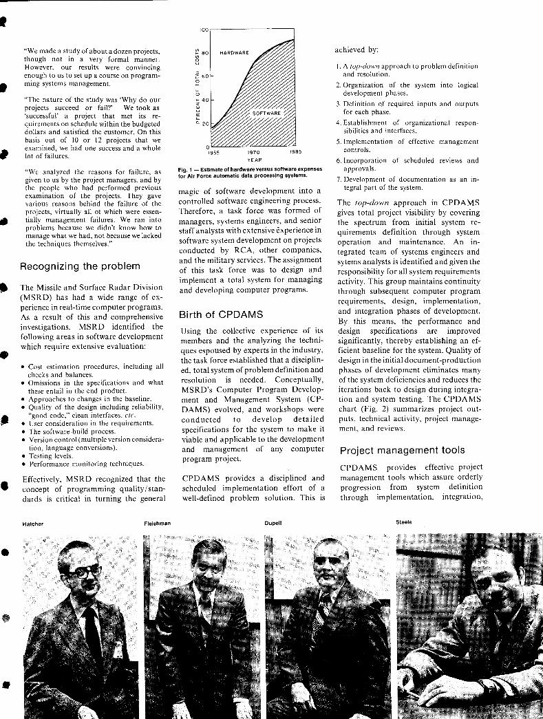
SOFTWARE is big business. Total costs for computer software in the United States exceed $10 billion annually, more than 1 % of the gross national product.. Major technological advancements have resulted in significant decreases in the cost of computer hardware, but related software costs continue to escalate rapidly. The recent World-Wide Military Command and Control SysteIl1a (WWM CCS) computer procurement was" estimated to involve expenditures of $50 to $100 million for hardware and $722 million for software. I An estimate for NASA was an annual expenditure of $100 million for hardware and $200 million for software. • Although the software-hardware cost ratio appears disproportionate now, the imbalance is forecast to increase rapidly in the years ahead as hardware gets cheaper and software (people) costs continue to go up. The Air Force conducted. a comprehensive study to estimate costs of software and hardware for command and control systems through 1985. Fig. I shows the estimate for software expenditures in the Air Force going to over 90% of the total automatic data processing system costs by 1985.2
•
The infancy of the software development process is emphasized by the number of computer program projects that have gone out of control, resulting in time slippages and cost overruns. Study after. study has shown that the software in-~ dustry has not profited from previous experience and tends to propagate the same errors in the development and management of computer programs. These points were emphasized by W. Boehm:3
•
"The CClP-85 study found that the problems of software productivity on medium or large projects are largely problems of management: of thorough organization, good contingency planning, thoughtful establishment of measurable project milestones, continuous monitoring. on whether the milestones are properly passed, and prompt investigation and corrective action in case they are not. In the software management area, one of the major difficulties is the transfer of experience from one project to the next. For example, many of the lessons learned as far back as SAGE are often ignored in today's software developments."
The management problem was also stated well by J. Aron at the 1969 Second NATO Conference on Software Engineering:
Reprint RE-19-5-16 Final manuscript received November 9, 1972. •
•
•
•
..
•
•
•
•
"We made a study of about a dozen projects, though not in a very formal manner. However, our results were convincing enough to us to set up a course on programming systems management.
"The nature of the study was 'Why do our projects succeed or fail?' We took as 'successful' a project that met its requirements on schedule within the budgeted dollars and satisfied the customer. On this basis out of 10 or 12 projects that we examined, we had one success and a whole lot of failures.
"We analyzed the reasons for failure, as given to us by the project managers, and by the people who had performed previous examination of the projects. They gave various reasons behind the failure of the projects, virtually all of which were essentially management failures. We ran into problems because we didn't know how to manage what we had, not because we lacked the techniques themselves."
Recognizing the problem
The Missile and Surface Radar Division (MSRD) has had a wide range of experience in real-time computer programs. As a result of this and comprehensive investigations, MSRD identified the following areas in software development which require extensive evaluation:
• Cost estimation procedures, including all checks and balances.
• Omissions in the specifications and what these entail in the end product.
• Approaches to changes in the baseline. • Quality of the design including reliability,
"good code," clean interfaces, etc. • User consideration in the requirements. • The software-build process. • Version control (multiple version considera
tion, language conversions). • Testing levels. • Performance monitoring techniques.
Effectively, MSRD recognized that the concept of programming quality I standards is critical in turning the general
Hatcher Fleishman
100.------------,
~ 80 HARDWARE <f> o U
..J
;: 60 o I-
... o I- 40 z w U Q:
W
a. 20
1970 1985
YEAR
Fig. 1 - Estimate of hardware versus software expenses for Air Force automatic data processing systems.
magic of software development into a controlled software engineering process. Therefore, a task force was formed of managers, systems engineers, and senior staff analysts with extensive experience in software system development on projects conducted by RCA, other companies, and the military services. The assignment of this task force was to design and implement a total system for managing and developing computer programs.
Bi rth of CPDAMS
Using the collective experience of its members and the analyzing the techniques espoused by experts in the industry, the task force established that a disciplined, total system of problem definition and resolution is needed. Conceptually, MSRD's Computer Program Development and Management System (CPDAMS) evolved, and workshops were conducted to develop detailed specifications for the system to make it viable and applicable to the development and management of any computer program project.
CPDAMS provides a disciplined and scheduled implementation effort of a well-defined problem solution. This is
Dupell
achieved by:
I. A lOp-down approach to problem definition and resolution.
2. Organization of the system into logical development phases.
3. Definition of required inputs and outputs for each phase.
4. Establishment of organizational responsibilities and interfaces.
5. Implementation of effective management controls.
6. Incorporation of scheduled reviews and approvals.
7. Development of documentation as an integral part of the system.
The top-down approach in CPDAMS gives total project visibility by covering the spectrum from initial system requirements definition through system operation and maintenance. An integrated team of systems engineers and sytems analysts is identified and given the responsibility for all system requirements activity. This group maintains continuity through subsequent computer program requirements, design, implementation, and integration phases of development. By this means, the performance and design specifications are improved significantly, thereby establishing an efficient baseline for the system. Quality of design in the initial document-production phases of development eliminates many of the system deficiencies and red uces the iterations back to design during integration and system testing. The CPDAMS chart (Fig. 2) summarizes project outputs, technical activity, project management, and reviews.
Project management tools
CPDAMS provides effective project management tools which assure orderly progression from system definition through implementation, integration,
Steele
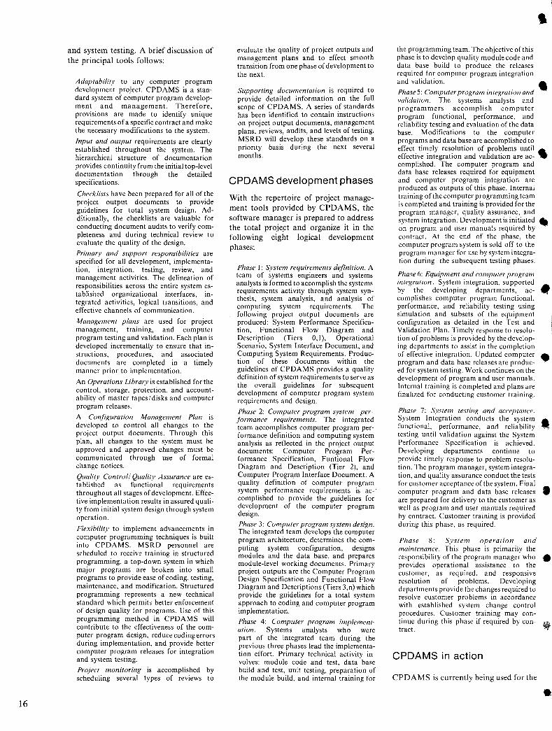
16
and system testing. A brief discussion of the principal tools follows:
Adaptability to any computer program development project. CPDAMS is a standard system of computer program development and management. Therefore, provisions are made to identify unique requirements of a specific contract and make the necessary modifications to the system.
Input and output requirements are clearly established throughout the system. The hierarchical structure of documentation provides continuity from the initial top-level documentation through the detailed specifications.
Checklists have been prepared for all of the project output documents to provide guidelines for total system design. Additionally, the checklists are valuable for conducting document audits to verify completeness and during technical review to evaluate the quality of the design.
Primary and support responsibilities are specified for all development, implementation, integration, testing, review, and management activities. The delineation of responsibilities across the entire system established organizational interfaces, integrated activities, logical transitions, and effective channels of communication.
Management plans are used for project management, training, and computer program testing and validation. Each plan is developed incrementally to ensure that instructions, procedures, and associated documents are completed in a timely manner prior to implementation.
An Operations Library is established forthe control, storage, protection, and accountability of master tapes/ disks and computer program releases.
A Configuration Management Plan is developed to control all changes to the project output documents. Through this plan, all changes to the system must be approved and approved changes must be communicated through use of formal change notices.
Quality Control/ Quality Assurance are established as functional requirements throughout all stages of development. Effective implementation results in assured quality from initial system design through system operation.
Flexihility to implement advancements in computer programming techniques is built into CPDAMS. MSRD personnel are sched uled to receive training in structured programming, a top-down system in which major programs are broken into small programs to provide ease of coding, testing, maintenance, and modification. Structured programming represents a new technical standard which permits better enforcement of design quality for programs. Use of this programming method in CPDAMS will contribute to the effectiveness of the computer program design, reduce coding errors during implementation, and provide better computer program releases for integration and system testing.
Project monitoring is accomplished by scheduling several types of reviews to
evaluate the quality of project outputs and management plans and to effect smooth transition from one phase of development to the next.
Supporting documentation is required to provide detailed information on the full scope of CPDAMS. A series of standards has been identified to contain instructions on project output documents, management plans, reviews, audits, and levels of testing. MSRD will develop these standards on a priority basis during the next several months.
CPDAMS development phases
With the repertoire of project management tools provided by CPDAMS, the software manager is prepared to address the total projes:t and organize it in the following eight logical development phases:
Phase I: System requirements definition. A team of systems engineers and systems analysts is formed to accomplish the systems requirements activity through system synthesis, system analysis, and analysis of computing system requirements. The following project output documents are produced: System Performance Specification, Functional Flow Diagram and Description (Tiers 0, I), Operational Scenario, System Interface Document, and Computing System Requirements. Production of these documents within the guidelines of CPDAMS provides a quality definition of system requirements to serve as the overall guidelines for subsequent development of computer program system requirements and design.
Phase 2: Computer program system performance requirements. The integrated team accomplishes computer program performance definition and computing system analysis as reflected in the project output documents: Computer Program Performance Specification, Funtional Flow Diagram and Description (Tier 2), and Computer Program Interface Document. A quality definition of computer program system performance requirements is ac-' complished to provide the guidelines for development of the computer program design.
Phase 3: Computer program system design. The integrated team develops the computer program architecture, determines the computing system configuration, designs modules and the data base, and prepares module-level working documents. Primary project outputs are the Computer Program Design Specification and Functional Flow Diagram and Descriptions (Tiers 3,n) which provide the guidelines for a total system approach to coding and computer program implementation.
Phase 4: Computer program implementation. Systems analysts who were part of the integrated team during the previous three phases lead the implementation effort. Primary technical activity involves: module code and test, data base build and test, unit testing, preparation of the module build, and internal training for
the programming team. The objective of this phase is to develop quality module code and data base build to produce the releases required for computer program integration and validation.
Phase 5: Computer program integration and • validation. The systems analysts and programmers accomplish computer program functional, performance, and reliability testing and evaluation of the data base. Modifications to the computer programs and data base are accomplished to effect timely resolution of problems until .. effective integration and validation are ac- ... complished. The computer program and data base releases required for equipment and computer program integration are produced as outputs of this phase. Internal training of the computer programming team is completed and training is provided for the program manager, quality assurance, and system integration. Development is initiated .. on program and user manuals required by contract. At the end of the phase, the computer program system is sold off to the program manager for use by system integration during the subsequent testing phases.
Phase 6: Equipment and computer program integration. System integration, supported • by the developing departments, accomplishes computer program functional, performance, and reliability testing using simulation and subsets of the equipment configuration as detailed in the Test and Validation Plan. Timely response to resolu-tion of problems is provided by the develop-ing departments to assist in the completion of effective integration. Updated computer • program and data base releases are produc-ed for system testing. Work continues on the development of program and user manuals. Internal training is completed and plans are finalized for conducting customer training.
Phase 7: System testing and acceptance. System Integration conducts the system • functional, performance, and reliability ~ testing until validation against the System Performance Specification is achieved. Developing departments continue to provide timely response to problem resolution. The program manager, system integration, and quality assurance conduct the tests for customer acceptance of the system. Final computer program and data base releases • are prepared for delivery to the customer as well as program and user manuals required by contract. Customer training is provided during this phase, as required.
Phase 8: System operation and maintenance. This phase is primarily the responsibility of the program manager who • provides operational assistance to the customer, as required, and responsive resolution of problems. Developing departments provide the changes required to resolve customer problems in accordance with established system change control procedures. Customer training may continue during this phase if required by contract.
CPDAMS in action
CPDAMS is currently being used for the
•
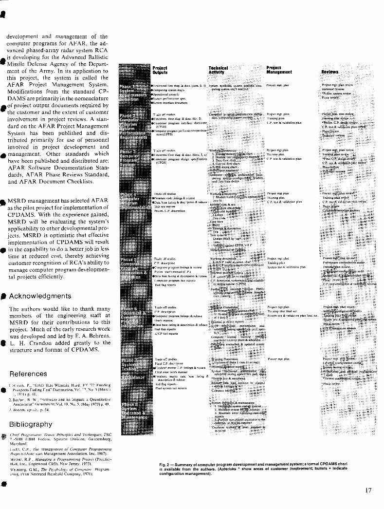
• development and management of the computer programs for AFAR, the advanced phased-array radar system RCA
• is developing for the Advanced Ballistic Missile Defense Agency of the Department of the Army. In its application to this project, the system is called the AF AR Project Management System. Modifications from the standard CPDAMS are primarily in the nomenclature
_of project output documents required by the customer and the extent of customer involvement in project reviews. A standard on the AFAR Project Management System has been published and distributed primarily for use of personnel involved in project development and
• management. Other standards which have been published and distributed are: AFAR Software Documentation Standards, AFAR Phase Reviews Standard, and AFAR Document Checklists.
,. MSRD management has selected AFAR as the pilot project for implementation of CPDAMS. With the experience gained, MSRD will be evaluating the system's applicability to other developmental projects. MSRD is optimistic that effective implementation of CPDAMS will result
• in the capability to do a better job in less time at reduced cost, thereby achieving customer recognition of RCA's ability to manage computer program developmental projects efficiently.
• Acknowledgments
•
•
•
The authors would like to thank many members of the engineering staff at MSRD for their contributions to this project. Much of the early research work was developed and led by E. A. Behrens. L. H. Crandon added greatly to the structure and format of CPDAMS.
References
I. Hirsch, P .. "GAO Hits Wimmix Hard; FY '72 Funding Prospects Fading Fast" Datamation. Vol. 17, No.5 (March I. 1971) p. 41.
2. Boehm, B. W., "Software and its Impact; a Quantitative Assessment" j)afamation, Vol. 19. No.5, (May 1973) p. 49.
J. Boehm. up cit .. p. 54.
Bibliography ChilI Programmer Teams Principles and Techniques, FSC 71-5108 (IBM Federal Systems Division. Gaithersburg, Maryland).
Lccht. c.P .. The Management of Computer Programming ProjeCls (American Management Association. Inc. 1967),
Metzer. R.P .. A1anaging a ProKramming Project (Prenticf!Hall. Inc .. Englewood Cliffs. New Jersey. 1973).
Weinberg. G.M., 771e Psy<;hology of Computer ProgramlI1ing, (Van Nostrand Reinhold Company, 1971).
program interface document
ec"m .. ""pm,",mperfonnance specifica-
program design specification
listing &
Final system test reports
Technical ActlYlty
System synthesis. system analysis computing system req'ts analysis
Computer program performance defini~ tion. computing system analysis
Working Documc.uo; I. Timing/memory status chart 2. Module intcrconnectivity diagram 3. Data flow chart 4. Control flow chart 5. File access chart 6. Project notebook
Computer program arehitecture. computing system configuration. module and data base design
Working Documents 7. Module build chart{plus updates. of 1 thm 6)
Module code &. test Code desk cbk debug Code cbk by supv Listings Test code
Data base lluild Listings &. description Test
Unit tests Design check by supv Tests. Validate against CPDS. valU
Initiate internal1)p training
Working documents -8, E/ep build sequence chart 9. EfCPinterfacecharts(plllilupdatesof I thru 7)
Informal pmblelfi reports
c.P. system Setl off to PMO C.P. functional. performance and reliabili~
ty testing against (CPPS)
Further CP training~ initiate PMO. systems engineerIng, systems integration training
Working Documents 10. System build sequence chait 11. System interface charts plus updates of 1 thtu9
Informal p{obleom reports E/ep functional. performance and
reliability testing against 'lIYS. perf. ~pec SIS
Complete internal training, Initiate customer training plans & schedules
Data base evaluation & updated -system build
Working Documents Updates of items 1 lhm II as req'd
Informal problem reports . System functional performance and
reliability testing against Sys. perl. spec
"'System test & acceptance
System data base updates to support system testing
Customer training
System operation & maintenance I. Implement system change control 2. Maintain system MTBF records 3. Ma:i.ntain error reporting/statistical reports 4. Provide operational assistance to tbe customer as may be requited.
Customer training &: misc. -SUpport as requi~
Project Management
Project mgt. plan
Project mgt. plan
Training plan
C. P. test & validation plan
Project mgt plan
Training plan
C. P. test & validation plan
Project mgt plan
Training plan
c.P. test & validation plan
Project mgt plan
Training plan
System test & validation plan
Project mgt plan
Training plan final ver.
System test & validation plan final ver.
Project mgt plan
ReYlews
Project mgt. plan review
Technical reviews
"'Prelim. system review
Phase review
Project mgt. plan review
Training plan review
·Prelim. C.P. design review
C.P. test &. validation plan review
Phase review
Technical reviews
Project mgt. plan review
Training plan review
·Final C.P. design review
c.P. test & ~idation plan review
Phas.e r~view
Technical reviews
Project mgt. plan review
Training plan review
CPo test &. validation plan review
Phase review
c.p, implementation reviews
Project mgt. plan review
Preliminary configuration audits
Training plan review
"Functional configuration audit
System test & validation plan review
Phasertview
c.p, implementation & validation reviews
Project ~mgt. plan review·
Infonnal (;oitfigl.iration audits
Training plan'final review
System test &. validation plan final review
Phase review
E/CP integration' reviews
Project mgt. plan review
Informal confIguration audits Systeql testing reviews
.Functional and physical configuration audit
*Formalqualification review
Phase revIew
Fig. 2 - Summary of computer program development and management system; a formal CPDAMS chart is available from the authors. (Asterisks * show areas of customer involvement; bullets • indicate configuration management).
17
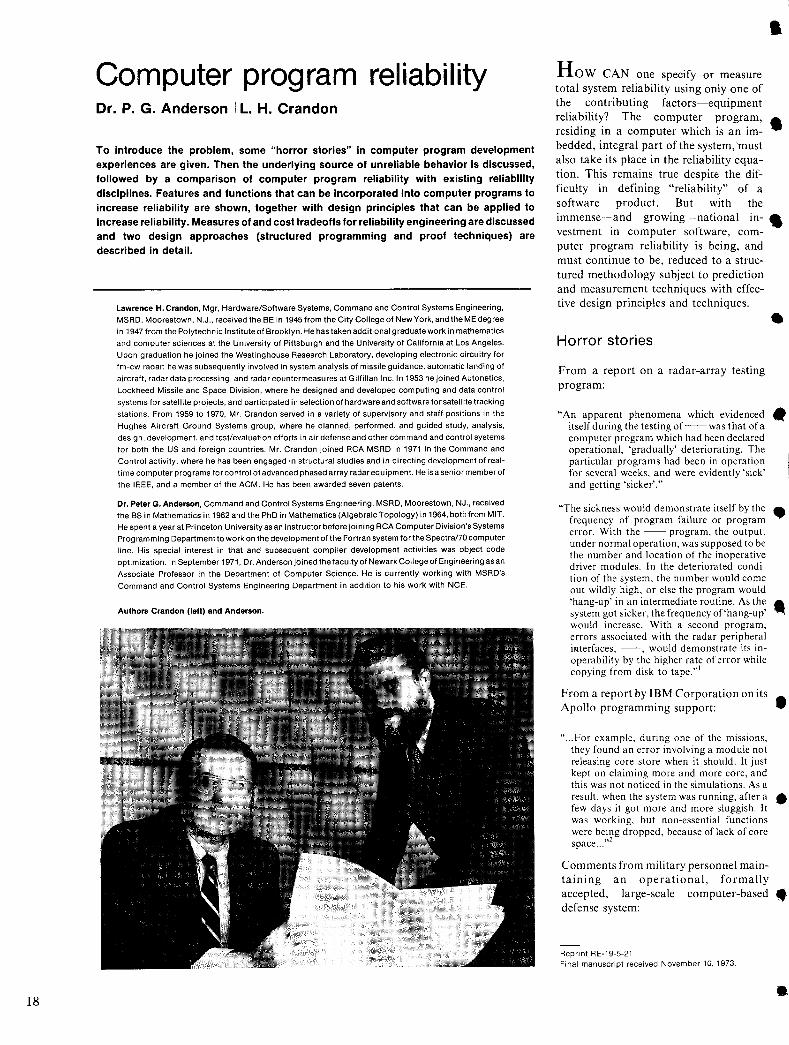
18
Computer program reliability Dr. P. G. Anderson I L. H. Crandon
To introduce the problem, some "horror stories" in computer program development experiences are given. Then the underlying source of unreliable behavior is discussed, followed by a comparison of computer program reliability with existing reliability disciplines. Features and functions that can be incorporated into computer programs to increase reliability are shown, together with design principles that can be applied to increase reliability. Measures of and cost tradeoffs for reliability engineering are discussed and two design approaches (structured programming and proof techniques) are described in detail.
Lawrence H. Crandon, Mgr, Hardware/Software Systems, Command and Control Systems Engineering, MSRD, Moorestown, N.J., received the BE in 1945 from the City College of New York, and the ME degree
in 1947 from the Polytechnic Institute of Brooklyn. He has taken additional graduate work in mathematics
and computer sciences at the University of Pittsburgh and the University of California at Los Angeles. Upon graduation he joined the Westinghouse Research Laboratory, developing electronic circuitry for
fm-cw radar; he was subsequently involved in system analysis of missile guidance, automatic landing of
aircraft, radar data processing, and radar countermeasures at Gilfillan Inc. In 1953 he joined Autonetics,
Lockheed Missile and Space Division, where he designed and developed computing and data control
systems for satellite projects, and participated in selection of hardware and software for satellite tracking stations. From 1959 to 1970, Mr. Crandon served in a variety of supervisory and staff positions in the
Hughes Aircraft Ground Systems group, where he planned, performed, and guided study, analysis,
design, development, and test/evaluation efforts in air defense and other command and control systems for both the US and foreign countries. Mr. Crandon joined RCA MSRD in 1971 in the Command and
Control activity, where he has been engaged in structural studies and in directing development of realtime computer programs for control of advanced phased array radar equipment. He is a senior member of
the IEEE, and a member of the ACM. He has been awarded seven patents.
Dr. Peter G. Anderson, Command and Control Systems Engineering, MSRD, Moorestown, NJ., received the BS in Mathematics in 1962 and the PhD in Mathematics (Algebraic Topology) in 1964, both from MIT.
He spent a year at Princeton University as an instructor before joining RCA Computer Division's Systems Prog ramm ing Department to work on the development of the Fortran system for the Spectra170 computer
line. His special interest in that and subsequent compiler development activities was object code
optimization. In September 1971, Dr. Anderson joined the faculty of Newark College of Engineering as an
Associate Professor in the Department of Computer Science. He is currently working with MSRD's
Command and Control Systems Engineering Department in addition to his work with NCE.
Authors Crandon (left) and Anderson.
How CAN one specify or measure total system reliability using only one of the contributing factors-equipment reliability? The computer program, residing in a computer which is an imbedded, integral part of the system, 'must also take its place in the reliability equation. This remains true despite the difficulty in defining "reliability" of a software product. But with the immense-and growing-national investment in computer software, computer program reliability is being, and must continue to be, reduced to a structured methodology subject to prediction and measurement techniques with effective design principles and techniques.
Horror stories
From a report on a radar-array testing program:
"An apparent phenomena which evidenced itself during the testing of-- was that ofa computer program which had been declared operational, 'gradually' deteriorating. The particular programs had been in operation for several weeks, and were evidently 'sick' and getting 'sicker'."
"The sickness would demonstrate itself by the frequency of program failure or program error. With the -- program, the output, under normal operation, was supposed to be the number and location of the inoperative driver modules. In the deteriorated condition of the system, the number would come out wildly high, or else the program would 'hang-up' in an intermediate routine. As the system got sicker, the frequency of'hang-up' would increase. With a second program, errors associated with the radar peripheral interfaces, --, would demonstrate its inoperability by the higher rate of error while copying from disk to tape.,,1
•
•
•
•
From a report by IBM Corporation on its • Apollo programming support:
..... For example, during one of the missions, they found an error involving a module not releasing core store when it should. It just kept on claiming more and more core, and this was not noticed in the simulations. As a result, when the system was running, after a • few days it got more and more sluggish. It was working, but non-essential functions were being dropped, because of lack of core space ... '"
Comments from military personnel maintaining an operational, formally accepted, large-scale computer-based. defense system:
Reprint RE-19-5-21 Final manuscript received November 10, 1973.
•
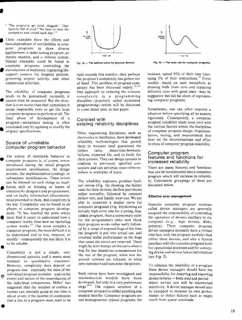
• .. 'The programs get tired, sluggish.' 'They
become full of crud.' 'We have to clear the computers and reload each day.' "
• These examples show the effects and time-dependence of unreliability in computer programs in three diverse applications: a radar testing program, an Apollo mission, and a defense system. Similar examples could be found in computer programs controlling the
• manufacture of medicines, regulating lifesupport systems for hospital patients, governing airport activity, and other commercial activities.
The reliability of computer programs needs to be guaranteed; currently, it
• cannot even be measured. But the situation is even worse than that: sometimes it seems impossible even to get the large computer programs to perform at all. The final phase of development of a program-acceptance testing-is often
• concluded only by agreeing to modify the original specifications.
Source of unreliable computer program behavior
The source of unreliable behavior in • computer programs is, of course, errors
introduced during the initial program requirements specification, the design process, the implementation (coding), or subsequent modifications. These errors can be blamed on such things as insuf-
_ ficient skill or training or lapses of attention by designers and programmers, and on faulty information (documentation) provided to them. But complexity is the key. Complexity can be found in all phases of computer program development. "It has reached the point where
• users find it easier to understand how a computer works than how an operating system works."] The more complex a computer program, the more difficult it is to understand and to test, measure, or modify-consequently the less likely it is to be reliable. •
•
Complexity is not a simple, onedimensional quantity and it seems most resistant to quantitative treatment. However, complexity does depend on program size-especially the sizes of the individual program modules-and on the extent and nature of the interrelations of the individual components. Miller4 has suggested that the number of entities a human can mentally grasp at one time is about seven; if the number of constraints that a line in a program must meet to be
FAILURE RATE
T1ME---+
Fig. 1 a - The bathtub curve for physical devices.
right exceeds this number, then perhaps the program's complexity has gotten out of hand. This problem of program complexity has been discussed widely.5,6,7,8 One approach to reducing the extreme complexity is a programming discipline-popularly called .structured programming-which will be discussed in some detail later in this paper.
Contrast with existing reliability disciplines
Other engineering disciplines, such as electronics or mechanics, have developed reliability methodologies that permit them to measure (and guarantee) the failure rates, mean-time-betweenfailures, expected life, and so forth, for their systems. They can design systems to conform to previously specified constraints and can advertize mean-time-tofailure in mUltiples of years.
The reliability engineers produce bathtub curves (Fig. la) showing the failure rates for their devices; the first part shows infant mortality, followed by constant failure rate, and finally wear-out. We are able to construct a similar curve for computer programs (Fig. I b) showing an initially high error rate for a young, bugridden program, then a momentary calm for the programmers (who now think their program works rather well), followed by a surge of exposed bugs at the time the program is put into actual use, and eventual stable performance as the bugs that cause the errors are removed. There might be later humps on the curve when a bug fix has disastrous consequences for the rest of the program, when new improved versions are released, or when new customers and uses enter the picture.
Such curves have been investigated and mathematical models have been developed, but only to a very preliminary stage.9
-IJ The organic structure of a
computer program is unlike anything else studied thus far. Computer programs are not homogeneous; typical programs, for
ERROR RATE
TIME --+
Fig. 1 b - The error rate for computer programs.
instance, spend 95% of their time exercising 5% of their instructions. 14 Error models-based on such metaphors as drawing balls from urns and replacing defective ones with good ones-may be suggestive but fall far short of representing computer programs.
Nonetheless, one can often improve a situation before specifying all its aspects rigorously. Consequently, a computer program reliability study must start with the various factors within the disciplines of computer program design, implementation, testing, and measurement that bear on the determinations and effectiveness of computer program reliability.
Computer program features and functions for increased reliability There are many features and functions that can be incorporated into a computer program which will increase its reliability, Convenient groupings of these are discussed below,
Effective error management
Separate computer program modules called device managers are generally assigned the responsibility of controlling the operation of devices ancillary to the computer (e. g., tape devices, disks, printers). These computer program device managers normally have a formal interface with the program modules that utilize these devices, and also a formal interface with the executive program both for operational purposes and for conveying device and service failure information (see Fig. 2).
To enhance the reliability of a program these device managers should have the responsibility for detecting and reporting device failures - both total and partialwhere service can still be maintained selectively. A device manager should also be equipped to monitor its own performance to detect failures such as might result from queue overloads.
19
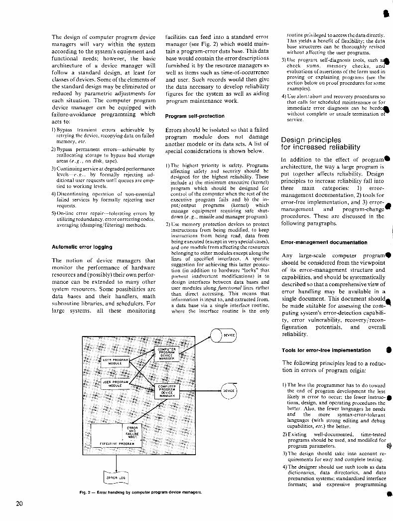
20
The design of computer program device managers will vary within the system according to the system's equipment and functional needs; however, the basic architecture of a device manager will follow a standard design, at least for classes of devices. Some of the elements of the standard design may be eliminated or reduced by parametric adjustments for each situation. The computer program device manager can be equipped with failure-avoidance programming which acts to: I) Bypass transient errors-achievable by
retrying the device. recopying data on failed memory. etc.
2) Bypass permanent errors-achievable by reallocating storage to bypass bad storage areas (e.g., on disk, tape).
3) Continuing service at degraded performance levels-e. g., by formally rejecting additional user requests until queues are emptied to working levels.
4) Discontinuing operation of non-essential failed services by formally rejecting user requests.
5) On-line error repair-tolerating errors by utilizing redundancy, error correcting codes, averaging (damping/filtering) methods.
Automatic error logging
The notion of device managers that monitor the performance of hardware resources and (possibly) their own performance can be extended to many other system resources. Some possibilities are data bases and their handlers, math subroutine libraries, and schedulers. For large systems, all these monitoring
facilities can feed into a standard error manager (see Fig. 2) which would maintain a program-error data base. This data base would contain the error descriptions furnished it by the resource managers as well as items such as time-of-occurrence and user. Such records would then give the data necessary to develop reliability figures for the system as well as aiding program maintenance work.
Program self-protection
Errors should be isolated so that a failed program module does not damage another module or its data sets. A list of special considerations is shown below.
I) The highest "priority is safety. Programs affecting safety and security should be designed for the highest reliability. These include a) the minimum executive (kernel) program which should be designed for control of the computer when the rest of the executive program fails and b) the input/ output programs (kernel) which manage equipment requiring safe shutdown (e.g., missile and manager program).
2) Use memory protection devices to protect instructions from being modified, to keep instructions from being read, data from being executed (except in very special cases), and one module from affecting the resources belonging to other modules except along the lines of specified interfaces. A specific suggestion for achieving this latter protection (in addition to hardware "locks" that prevent inadvertent modifications) is to design interfaces between data bases and user modules along functional lines rather than direct accessing. This means that information is input to, and extracted from, a data base via a single interface routine, where the interface routine is the only
Fig. 2 - Error handling by computer program device managers.
routine privileged to access the data directly. This yields a benefit of flexibility; the data base structures can be thoroughly revised without affecting the user programs.
3) Use program self-diagnosis tools, such a. check sums, memory checks, and evaluations of assertions of the form used in proving or explaining programs (see the section below on proof procedures for some examples).
4) Use alert/ abort and recovery procedures so that calls for scheduled maintenance or for immediate error diagnosis can be heede. without complete or unsafe termination oj service.
Design principles for increased reliability
In addition to the effect of program. architecture, the way a large program is put together affects reliability. Design principles to increase reliability fall into three main categories: I) errormanagement documentation, 2) tools for error-free implementation, and 3) error- • management and program-change procedures. These are discussed in the following paragraphs.
Error-management documentation
Any large-scale computer program. should be considered from the viewpoint of its error-management structure and capabilities, and should be systematically described so that a comprehensive view of error handling may be available in a single document. This document should_ be made suitable for assessing the computing system's error-detection capability, error vulnerability, recovery / reconfiguration potentials, and overall reliability.
Tools for error-free implementation •
The following principles lead to a reduction in errors of program origin:
I) The less the programmer has to do toward the end of program development the less likely is error to occur; the fewer instruc-. ' tions, design, and operating procedures the better. Also, the fewer languages he needs and the more syntax-error-tolerant languages (with strong editing and debug capabilities, etc.) the better.
2) Existing well-documented, time-tested programs should be used, and modified for program parameters. lit
3) The design should take into account requirements for easy and complete testing.
4) The designer should use such tools as data dictionaries, data directories, and data preparation systems; standardized interface formats; and expressive programming
•
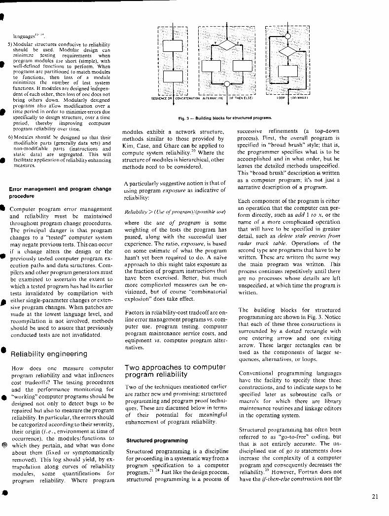
•
•
•
•
languages 15-19 .
5) Modular structures conducive to reliability should be used. Modular design can minimize testing requirements when program modules are short (simple), with well-defined functions to perform. When programs are partitioned to match modules to functions, then loss of a module minimizes the number of lost system functions. If motlules are designed independent of each other, then loss of one does not bring others down. Modularly designed programs also allow modification over a time period in order to minimize errors due specifically to design structure, over a time period, thereby improving computer program reliability over time.
6) Modules should be designed so that their modifiable parts (generally data sets) and non-modifiable parts (instructions and static data) are segregated. This will facilitate application of reliability enhancing measures.
Error management and program change procedure
• Computer program error management and reliability must be maintained throughout program change procedures. The principal danger is that program changes to a "tested" computer system may negate previous tests. This can occur if a change alters the design or the
• previously tested computer program execution paths and data structures. Compilers and other program generators must be examined to ascertain the extent to which a tested program has had its earlier tests invalidated by compilation with
" either single-parameter changes or extensive program changes. When patches are made at the lowest language level, and recompilation is not involved, methods should be used to assure that previously conducted tests are not invalidated.
• Reliability engineering
How does one measure computer program reliability and what influences cost tradeoffs? The testing procedures and the performance monitoring for
• "working" computer programs should be designed not only to detect bugs to be repaired but also to measure the program reliability. In particular, the errors should be categorized according to their severity, their origin (i. e. , environment at time of occurrence), the modules/functions to which they pertain, and what was done about them (fixed or symptomatically
•
removed). This log should yield, by extrapolation along curves of reliability modules, some quantifications for program reliability. Where program
---- --1 I I I I I I I r---'--,: I
'---,----' I I I I
,----- ----1 I I I I I I I I I I I I I I I I I I I I I I I I I I I I I I L __________ J I : L ____________ .J
SEOUENCE OR CONCATENATION ALTERNATiVE
Fig. 3 - Building blocks for structured programs.
modules exhibit a network structure, methods similar to those provided by Kim, Case, and Ghare can be applied to compute system reliability.20 Where the structure of modules is hierarchical, other methods need to be considered.
A particularly suggestive notion is that of using program exposure as indicative of reliability:
Reliability> ( Use of program) / (possible use)
where the use of program is some weighting of the tests the program has passed, along with the successful user experience. The ratio, exposure, is based on some estimate of what the program hasn't yet been required to do. A naive approach to this might take exposure as the fraction of program instructions that have been exercised. Better, but much more complicated measures can be envisioned, but of course "combinatorial explosion" does take effect.
Factors in reliability-cost tradeoff are online error management programs vs. computer use, program testing, computer program maintenance service costs, and equipment vs. computer prognim alternatives.
Two approaches to computer program reliability
Two of the techniques mentioned earlier are rather new and promising: structured programming and program proof techniques. These are discussed below in terms of their potential for meaningful enhancement of program reliability.
Structured programming
Structured programming is a discipline for proceeding in a systematic way from a program specification to a computer program.2I-28 Just like the design process, structured programming is a process of
successive refinements (a top-down process). First, the overall program is specified in "broad brush" style; that is, the programmer specifies what is to be accomplished and in what order, but he leaves the detailed methods unspecified. This "broad brush" description is written as a computer program; it's not just a narrative description of a program.
Each component of the program is either an operation that the computer can perform directly, such as add I to x, or the name of a more complicated operation that will have to be specified in greater detail, such as delete stale entries from radar track table. Operations of the second type are programs that have to be written. These are written the same way the main program was written. This process continues repetitively until there are no processes whose details are left unspecified, at which time the program is written.
The building blocks for structured programming are shown in Fig. 3. Notice that each of these three constructions is surrounded by a dotted rectangle with one entering arrow and one exiting arrow. These larger rectangles can be used as the components of larger sequences, alternatives, or loops.
Conventional programming languages have the facility to specify these three constructions, and to indicate steps to be specified later as subroutine calls or macro's for which there are library maintenance routines and linkage editors in the operating system.
Structured programming has often been referred to as "go-to-free" coding, but that is not entirely accurate. The undisciplined use of go to statements does increase the complexity of a computer program and consequently decreases the reliability.20 However, Fortran does not have the if-then-else construction nor tht'
21
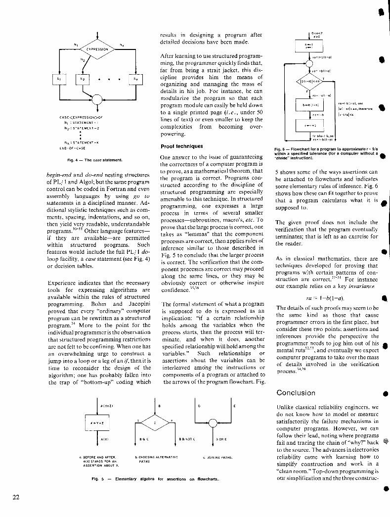
22
EXPRESSION
CASE <E XPRESSION>QF
NI : STATEMENT - I
N 2 : STATEMENT-2
Ni(: STATEMENT-i(
ENO-OF-CASE
Fig. 4 - The case statement.
begin-end and do-end nesting structures of PL/I and Algol; but the same program control can be coded in Fortran and even assembly languages by using go to statements in a disciplined manner. Additional stylistic techniques such as comments, spacing, indentations, and so on, then yield very readable, understandable programs. JO
-JJ Other language features
if they are available-are permitted within structured programs. Such features would include the full PL/I doloop facility, a case statement (see Fig. 4) or decision tables.
Experience indicates that the necessary tools for expressing algorithms are available within the rules of structured programming. Bohm and Jacopini proved that every "ordinary" computer program can be rewritten as a structured program.34 More to the point for the individual programmer is the observation that structured programming restrictions are not felt to be confining. When one has an overwhelming urge to construct a jump into a loop or a leg of an if, then it is time to reconsider the design of the algorithm; one has probably fallen into the trap of "bottom-up" coding which
B a c
results in designing a program after detailed decisions have been made.
After learning to use structured programming, the programmer quickly finds that, far from being a strait jacket, this discipline provides him the means of organizing and managing the mass of details in his job. For instance, he can modularize the program so that each program module can easily be held down to a single printed page (i. e., under 50 lines of text) or even smaller to keep the complexities from becoming overpowering.
Proof techniques
One answer to the issue of guaranteeing the correctness of a computer program is to prove, as a mathematical theorem, that the program is correct. Programs constructed according to the discipline of structured programming are especially amenable to this technique. In structured programming, one expresses a large process in terms of several smaller processes-subroutines, macro's, etc. To prove that the large process is correct, one takes as "lemmas" that the component processes are correct, then applies rules of inference similar to those described in Fig. 5 to conclude that the larger process is correct. The verification that the component processes are correct may proceed along the same lines, or they may be obviously correct or otherwise inspire confidence.35
,36
The formal statement of what a program is supposed to do is expressed as an implication: "if a certain relationship holds among the variables when the process starts, then the process will terminate, and when it does, another specified relationship will hold among the variables." Such relationships or assertions about the variables can be interleaved among the instructions or components of a program or attached to the arrows of the program flowchart. Fig.
B 8 NOT C o OR E
a. BEFORE AND AFTER. A(X) STANDS FOR AN ASSERTION ABOUT X.
b. CHOOSING ALTERNATIVE PATHS.
c. JOINING PATHS.
Fig. 5 - Elementary algebra for assertions on flowcharts ..
•
• ro=l-b(l-oJ
Ib(l-o)I<e:o T
ro=l-b(l-o),ond
10 (1-0)1 < EO I therefore
Ir-lIal<e: • Fig. 6 - Flowchart for a program to approximate r ~ l/a within a specified tolerance (for a computer without a • "divide" instruction).
5 shows some of the ways assertions can be attached to flowcharts and indicates some elementary rules of inference. Fig. 6 shows how these can fit together to prove that a program calculates what it is • supposed to. '
The given proof does not include the verification that the program eventually terminates; that is left as an exercise for the reader.
As in classical mathematics, there are techniques developed for proving that programs with certain patterns of construction are correct. 37-5 I For instance our example relies on a key invariance
ra = I-b(l-a).
The details of such proofs may seem to be
•
.. the same kind as those that cause programmer errors in the first place, but consider these two points: assertions and inferences provide the perspective the programmer needs to jog him out of his • mental ruts52
,5J, and eventually we expect com puter programs to take over the mass of details involved in the verification process.54
,28
Conclusion
Unlike classical reliability engineers, we do not know how to model or measure satisfactorily the failure mechanisms in computer programs. However, we can follow their lead, noting where programs fail and tracing the chain of "whyT' back to the source. The advances in electronics reliability came with learning how to simplify construction and work in a "clean room. " Top-down programming is our simplification and the three construc-
•
•
•
• tions comprise the programming "clean room."
Quantification will be an elusive solution for a long time. Much that goes wrong is attributable to human failure where complexity-which depends on much more than size-is the overwhelming factor.
• References
•
•
(I
•
•
•
I. Fox, E., "The Gradual Deterioration of a Computer Program," private comrnunicarion, (Jan. 2, 1971).
2. Buxton, J.N., Randell, B., eds., Software Engineering Techniques. Report on a 1969 Conference on Software Engineering Techniques. (Brussels, NATO Science Committee. 1970).
3. Mills, Harlan, "The Complexity of Programs," Program Tesl Melhods, W. C. Hetzel. cd. ([nglewood Cliffs, Prentice-Hall, Inc., 1973), pp 225-238.
4. Miller. George A .. "The Magical Number Seven, Plus or Minus Two: Some Limits on our Capacity for Processing Information," The PS)lch%gical Review, Vol. 63, No.2 (March 1956) pp 81-97.
5. Dermer. Jerry D .. "Differential Effects of Cognitive Complexity on the Organization of Management Information," MIT-Sloan School of Management, October 1972 (Work Paper 65-72).
6. Miller, George A.; Galanter, Eugene; Pribram, Karl H., Plans and the Structure o.{ Behavior, (New York, Holt, Rinehart & Winston, Inc., 1960).
7. Raisbeck, Gordon, b?formalion Theory: An Introduction for Scientists and Engineers, (Cambridge, M.I.T. Press, 1964), pp 47-49.
g. Van Emden, M.H., "An Ana.Iysis of Complexity," Mathematish Centrum (Amsterdam, 1971).
9. Coutinho, John De S., "Software Reliability Growth," Proc. q{1973 IEEE Symposium on Computer Software Reliahilily. pp 58-64.
10. Paige, M.R.; Balkovich, E.E., "On Testing Programs," Pmc. q{1973 IEEE Symposium on Computer Sofiware ReliahililY, pp. 23-27.
1 I. Schneidewind, Norman F., "An Approach to Software Reliability Prediction and Quality ControL" Prot. of the 1972 Fall Joint Computer COI?{erence, pp. 837-847.
12. Shooman, Martin L., "Operational Testing and Software Reliability Estimation During Program Development," Proc. of 1973 IEEE Symposium on Compuler Software Reliahilit.l', pp. 5\-57.
13. Shooman, Martin L., "Probabilistic Models for Software Reliability Prediction," Digest 0.( Papers, 1972 International Symposium on Fault- Tolerant Computing, pp.211-215.
14. Knuth. D.E., "An Empirical Study of Fortran Programs," S(?fiware Practice and Er:perience. Vol. I No. 2 (1971), pp. 105-133.
15. David, E.E .. "The Production of Software for Large Systems," Gianr C(Jll1puters:(Maidenhead, England, INFOTECH Ltd., 1971), pp. 403-414.
16. Falkofr. A.D., "Criteria for a System Design Language," So.flware Engineering Techniques, Report on a 1969 conference on software engineering techniques, (Brussels. NATO Science Committee, 1970), pp. 83-93.
17. Halstead, M.H., "Language Selection for Applications," Proc. (?{the 1973 National Computer Conference, pp. 211-214.
18. Henrikson, J.G.: Merwin, R.E" "Programming Language Efficiency in Real-Time Software Systems," Pmc. of the 1972 Spring .loint Computer Conference. pp. 49-54.
19. Steele, S.A.: Galbiati, LJ .. "Higher Order Language Evaluation for Real-Time Computer Systems," Asilomar Conference on Circuits. Systems, and Computers. Monterey, California, (Nov. 1973).
20. Kim. Young H.: Case, Kenneth E.; Ghare, P.M., "A Method of Computing Complex System Reliability," IEEE Transactions on Reliahility. Vol. R-21, No.4 (Nov. 1972). pp. 215-219.
21. Baker. F.T., "System Quality through Structured Programming," Proc. of the 1972 Spring Joint Computer Conference, pp. 339-344.
22. Benson, Jeoffry P., "Structured Programming Techniques," Proc. of 1973 IEEE Symposium on Computer sq(tl1'are Reliahility, pp. 143-147.
23. Bochmann. G.V., "Multiple Exits from a Loop without
the GOTO." CACM, Vol. 16. No.7 (July 1973), pp. 443-444.
24. Dijkstra, E.W., ":'\otes on Structured Programming," Technische Hogeschool Eindhoven, June 1971 (EWD-249 - 84 pages).
25. Mills, Harlan, "On the Development of Large Reliable Programs," Proc. ofl973 IEEE Symposium on Computer Softlt'are Reliability, pp. 155-160.
26. Mills, Harlan. "Top-Down Programming in Large Svstems," Debugging Techniques in Large sysrems, (Courant Computer Science Symposium I). R. Rustin. ed. (New York. NYU Press, 1971). pp. 41-45.
27. Peterson. W.W.: Kasami, T.; Tokura. N .. "On the Capabilities of While, Repeat, and Exit Statement," CACM, Vol. 16, No.8 (August 1973), pp. 503-512.
28. Snowdon, R.A .. "Pearl-A System for the Preparation and Validation of Structure Programs." Program Test Methods, W.e. Hetzel, ed. (Englewood Cliffs, PrenticeHall, Inc., 1973), pp. 57-72.
29. Dijkstra, E.W., "GOTO Statement Considered Harmful," CA CM, Vol. II. No.3 (March 1968), pp. 147-148.
30. Conrow. Kenneth; Smith. Ronald G., "Neater 2: A PL/I Source Statement Reformatter," CACM, Vol. 13, No. II (Nov. 1970). pp. 669-675.
31. Kernighan, B. W.; Plaugher. P .J., "Programming Style for Programmers and Language Designers," Proc. ~f1973 IEEE Symposium on Computer Software Reliahility, pp. 148-154.
32. Kreitzberg, Charles B.; Shneiderman, Ben, The Elements of Fortran Style. (New York, Hartcourt Brace Jovanovich, Inc., 1972).
33. McCracken, Daniel D.; Weinberg, Gerald M., "How to Write a Readable Fortran Program." Datamation, Vol. 18, No. 10 (Oct. 1972), pp. 73-77.
34. Bohm, e.; Jacopini, G .. "Flow Diagrams, Turing Machines, and Languages with only two Formation Rules." CACM, Vol. 9, No.5 (May 1966), pp. 366-371.
35. Polya, George, Mathematical Discovery, (New York, John Wiley & Sons, Inc., 1962).
36. Polya. George, How to Solve It, (Princeton, Princeton University Press, 1971).
37. Allen, e.D., "The Application of Formal Logic to Programs and Programming," IBM Syslem .lournal, Vol. 10. No. I (1971), pp. 2-38.
38. Dijkstra, E.W., "A Constructive Approach to the Problem of Program Correctness," BIT, Vol. 8, No.3 (1968). pp. 174-186.
39. Floyd, Robert W., "Assigning Meanings to Programs," Mathemafical Aspects ~(C()mputer Science, (Proceedings of Symposium in App. Math., 19), .I. T. Schwartz, ed., (Providence. American Mathematical Society, 1967), pp. 19-32.
40. Good, 0.1.; Ragland, L.e., "Nucleus--A Language of Provable Programs." Program Test Methods, W.e. Hetzel, Ed., (Englewood Cliffs, Prentice-Hall, Inc., 1973), pp.93-117.
41. Hoare, e.A.R., "An Axiomatic Basis for Computer Programming." CACM, Vol. 12, No. 10 (Oct. 1969), pp. 576-583.
42. Hoare, e.A.R., "Proof of a Program: Find,~' CACM, Vol. 14. No. I (Jan. 1971), pp. 39-45.
43. Hunt. B.R., "A Comment on Axiomatic Approaches to Programming, "CACM, Vol. 13. No.7 (July 1970), p. 452.
44. Kang, A.N.e., "On the Complexity of Proving Functions," Proc. (~f' the 1972 Spring .loint Computer Conierence, pp. 493-50 I.
45. King . .lames e., "Proving Programs to be Correct," IEEE Transacrionson Computers, Vol. C-20, No. II (Nov. 1971), pp. 1331-1336.
46. Levitt, Kark N., "The Application of Program-Proving Techniques to the Verification of Synchronization Processes," Proc. q( the 1972 Fall Joint Computer COJ~{erence, pp. 33-47.
47. Linden, T.A., "A Summary of Progress Toward Proving Program Correctness," Pro!'. of the 1972 Fall Joint Computer Conference, pp. 201-211.
48. London, R.L., "Certification of Algorithm 245 Treesort 3: Proof of Algorithms -,·A New Kind of Certification," CACM, Vol. 13, No.6 (June 1970), pp. 371-373.
49. Manna. Zohar; Ness, Stephen; Vuillemin, Jean, "Inductive Methods for Proving Properties of Programs." CACM, Vol. 16, No.8 (August 1973). pp. 491-502.
50. Manna, Zohar, "Computation of Recursive ProgramsTheory vs Practice." Proc. (~( the 1972 Spring Joint Computer Conference, pp. 219-223.
51. Nauer. Peter. "Proof of Algorithms by General Snapshots." BIT. Vol. 6, No.4, (1966). pp. 310-316.
52. De Bono, Edward. Latera! Thinking in Management, (New York. American Management Association, 1971).
53. Weinberg, Gerald M .. The Psychology of Computer ProgramminK, (New York, Van Nostrand-Reinhold Co .. 1971).
54. Brown. J.R.: Hoffman. R.H .. "Evaluating the Effectiveness of Software Verification-Practical Experient;e With an Automated Too!." Proc. of the 1972 Fall Joint Computer Conference, pp. 181-190.'
Bibliography
Baker. F.T., "Chief Programmer Team Management of Production Programming," IBM System Journal. Vol. II, No. I (1972). pp. 56-73.
Borgerson. Barry R .. "Dynamic Confirmation of System Integrity," Proc. o{ the 1972 Fall Joint Computer Conference, pp. 89-96.
Chandy, K.M.; Ramamoorthy, e.v.: Cowan, A., "A Framework for Hardware-Software Tradeoffs in the Design of Fault-Tolerant Computers," Proc. of the 1972 Fall Joim Computer Conference. pp. 55-63.
I-Iynn, RJ., "On the Smallest Number of Program Modules Needed to Duplicate Dynamic Independent Interactions." Proc. of 1973 IEEE Symposium on Computer Sqftware ReliahililI'. pp. 65-69.
hazcr, W.D., "Analysis of Combinatory Algorithms-A Sample of Current Methodology," Prol'. o.(the 1972 Spring Joint CompUfel' Conference, pp. 483-491.
heeman. Peter, "Functional Programming. Testing, and Machine Aids," Progrwl1 Test Methods, W.e. Hetzel, cd., (Englewood Cliffs, Prentice-Hall, Inc .. 1973), pp. 45-56.
Ciirard. E.; Rault, J.e., "A Programming Technique for Software Reliability," Pmc. qf 1973 IEEE Symposium on Computer Software Reliahility, pp. 44-50.
Gunderman, Richard E., "A Glimpse into Program Maintenance," Daramation, Vol. 19, No.6 (June 1973), pp. 99-101.
Hansler. E.: Mc Auliffe. G.K.; Wilkov, R.S., "Exact Calculation of Computer Network Reliability, "Pmc. (~( the 1972 Fall Joint Computer Conference, pp. 49-54.
Horning, J . .I.; Randell, Bo, "Process Structuring," CompUlinx Surv'.)'s, Vol. 5. No. I (March 1973) , pp. 5-30.
I.iskov, RH .. "A Design Methodology for Reliable Software Systems." Pmt'. (?l the 1972 Fall Joint CompuIl'r Conference, pp. 191-199.
Mills. H.D., "Syntax-Directed Documentation for PL 360." CACM, Vol. 13, No.4 (April, 1970), pp. 216-222.
:\aur, Randell, B. eds., Sqfiware Engineering, Report on a 1968 Conference on software engineering techniques, (Brussels, NATO Science committee. 1969).
Parnas, David L., "Some Conclusions from an Experiment in Software Engineering Techniques," Pw('. o(1he 1972 Fall .loin I CompUler C()flj'erencl', pp. 325-329.
Ramamoorthy, e.V.: Meeker, R.E.: Turner, J., "Design and Construction of an Automated Software Evaluation System," Pmc. (?/ Ihe 1973 IEEE Symposium on Computer S(diware Reliahility. pp. 28-37.
Rose, e. W" "Logos and the Software Engineer," Pwc. of the 1972 Fall.loint Computer CO/~f'erence, pro 311-323.
Schwart7, .I.T .. "What is Programming?," SETL Newsletter :'\lo. 33, Courant Institute of Mathematical Science, NYU, May 1971.
Schwartz. J.T., "On Programming--An Interim Report on the SEGL Project. Installment I: Generalities," Courant Institute of Mathematical Science. NYU. February 1973.
Wcnslcy, John H., "SIFT Software Implemented Fault rolerance," Proc. (?( the 1972 Fall Joint Computer Conference, pp. 243-253.
Wirth, Niklaus. "On Multiprogramming. Machine Coding, and Computer Organi7ation," CACM, Vol. 12, No.9 (Sept. 1969). pr. 489-498.
Woodger. M., "The Description of Computing Processes: Some Observations on Automatic Programming and Algol-60," Annual Rl'viel1' in Automatic ProgramminK. Vol. 3. R. Goodman. ed., (London. Pergamon Press Ltd .. 1963). pp. I-IS.
Zahn. Charles T.. "Graph-Theoretical Methods for Detecting and Describing Gestalt Clusters," IEEE Transanions 011
CompUlers. Vol. C-20. No. I. (Jan. 1971). pp. 68-86.
23
24
Impact of hardware/software tradeoffs in a command and control system J. c. Kulp
Within the last ten years, computers have become a critical link in large command and control systems. For example, in modern radar systems the phased array is totally controlled by computers, whereas the older mechanical radars closed the search and track loops by hardware. In the tradeoff decisions, however, hardware advantages still receive greater emphasis. This is because the software practitioner remains the "new boy on the block." He finds himself explaining his software interface problems in terms of hardware terminology, usually without a one-to-one correspondence. Likewise, the senior system engineer's background has more often been in hardware than in software, with resulting hardware orientation in the tradeoff decisions. One intent he-re is to stress the software viewpoint. This paper is divided into two sections. The first discusses areas of systems that are ideal candidates for hardware/software tradeoffs, and provides basic rules governing the decision process. The second section discusses hardware/software interface design approaches and their impact on the software design and system development.
T ODAY'S command and control systems are constantly evolving to meet new and changing requirements. This evolutionary process, quite naturally, exerts substantial influence on hardware/ software tradeoff decisions, particularly as current hardware technology becomes outdated and designers turn more to software modifications as the most cost-effective method of making system changes. U nquestionably, a major design requirement of any command and control system evolving today must be ease and reliability of modification.
Moreover, the basis for tradeoff decisions between hardware and software will continue to change as computer capabilities increase, processing speeds multiply, and multiprocessing technology becomes more widespread. Some of the more complicated functions normally associated with equipment will be available as part of the computer (e.g., FFT, coordinate conversions). Hence, evolution in computer capabilities as well as in hardware technology will continue to alter the outcome of hardware/ software tradeoffs.
I dentifyi ng hardware/software tradeoff areas
A prerequisite for identifying hardware/ software tradeoff areas is a
clear understanding of the system objectives and functional flow. From this point, an initial functional design can be developed as the basis for deriving the software elements for a tradeoff decision: • estimates of bulk data storage, functional execution requirements (both mathematical and logical), execution rates, data flow rates, data block sizes, and initial definition of the operator interface requirements.
With an initial functional layout in hand, it is practical to identify areas that are candidates for hardware/ software tradeoff studies. These areas can be classified in five categories.
1) Bulk data handling with fast processing • cycles
2) Independent algorithms with fast completion cycles
3) Incompatible processing loops
4) Real-time (ms to Ils) control algorithms
5) Mathematical models with complex com- • putations
Bulk data handling with fast processing cycle
Systems with large data bases and many elements that must be processed within a • short period of time are candidates for hardware/ software tradeoffs, because a total software implementation approach could easily consume an excessive amount of the computer execution time. An example is the identification of known satellites in space track systems. Satellite .. positions are calculated for specific times using their orbital elements, and these elements must be correlated with those of unrecognized detections within milliseconds to determine if an object is new or a known satellite. This process of • deriving correlation candidates for several thousand satellites each minute of the day is a bulk-data-handling problem. Performing a correlation with each of these candidates for a single search detection (which occurs several times per second) represents a fast processing cycle. •
Another example is the problem of keeping track of railroad rolling stock location in a fast transportation system. The track system must be organized in several thousand sections, and each train or car in the system must be associated with a • given section. This bulk data base is used
Reprint RE-19-5-22 Final manuscript received December 14, 1973.
•
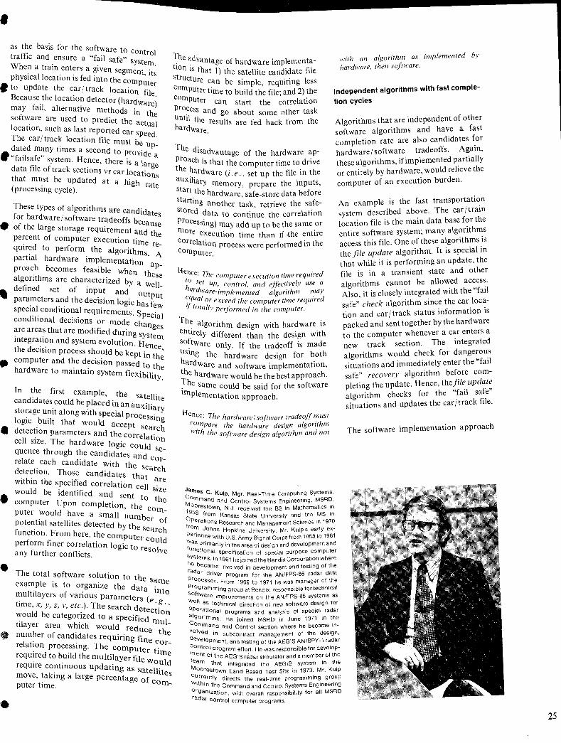
• as the basis for the softw
ff' are to Cont I
tra IC and ensure a "fail safe" ro When a train enters a give system.
h . n segment 't
p YSlcallocation is fed into th ' I S • to update the car/track I e c?mputer
B ocatlOn fil
ecause the location detector (ha d e. f '1 r Ware) may ai, alternative method ;
software are used to pred' t hS
.n the I
. IC t e actu I ocatlOn, such as last repo t d a
The car/track location fl'lr
e car speed. d
. e must be ated many times a second t . up-
• Hf'l f" 0 provide al sa e system. Hence th' a d f
'l ' ere IS alar ata I e of track sections ge h
vs car locati t at must be updated at h' ons (
. a Igh rat processlllg cycle). e
These types of algorithms are ca d' for hardware/ software trad ff n Idates
• f th I eo s becau
o e arge storage requ' se Irement and th percent of computer ex . . e . ecutlOn 11m qUired to perform the I . e re-
. I a gonthms A partla hardware imp I .' ementatlOn proach becomes feasible wh ap-I 'th en the a gon ms are character' d b se
defined set of inpu/ze
y a well-.. and Out
parameters and the decisio I' put special conditional requi n oglc has few
. . rements. Sp . conditIOnal decisions or d eClal mo e chan are areas that are modified d' ges . t . unng syst III egratlOn and system evol t' em th d
'. u Ion Hen e eCISlOn process should be ke' . ce,
• computer and the decision pt III the h d
passed to th ar ware to maintain syst fl' e em eXlbility.
In the first example th candidates could be place'd . e satellite
manauxT storage unit along with sp . I I lary I
. b eCJa proce . oglc uilt that would SSmg
• d . accept se
etectlOn parameters and th arch cell size. The hardware I ~ correlation
oglc could quence through the cand'd Se-
I I ates and
re ate each candidate . h Cor-d
. Wit the s etectlOn. Those cand'd earch 'th' I ates that
WI m the specified correlation ~re
• would be identified d cell Size an sent to computer. Upon complef the lOn, the c
•
•
puter would have a sm II om-. a numb potential satellites detected b h er of function. From here the y t e search
f. ,computer c
per orm fmer correlation I' ould f
oglc to res I any urther conflicts. 0 Ve
The total software solution to th example is to organize th d e same
1'1 - e ata'
mu tl ayers of various pa Into . rameters (e time, x, y, z, v, etc.). The search dete . ~., would be categorized to '. Chon '1 a specIfied tJ ayer area which would mul-
b redUce th
num er of candidates req " . e I
. Uinng fin re atlOn processing Th e Cor_ . . e compute . reqUired to build the multilayer file ~ tiine reqUire continuous updat' ould mg as Sat II' move, taking a large percent e Ites puter time. age of com_
The adv tio . antage of hardware implementa-str n IS that I) the satellite candidate file
Ucture ca b' ..
with an algorithm as implemented by hardware, then software.
com . n e Simple, requmng less puter time to build the fiJe- and 2) the
comput ' pr
er can start the correlation
Independent algorithms with fast comple
tion cycles ocess d until t an go about some other task
h d he results are fed back from the ar Ware.
The di d sa vantage of the hardware ap-proach i th . ' the h s at the computer time to dnve au 'I~rdware (i. e., set up the file in the sta~~ ~ary memory, prepare the inputs,
Algorithms that are independent of other software algorithms and have a fast completion rate are also candidates for hardware/ software tradeoffs. Again, these algorithms, if implemented partially or entirely by hardware, would relieve the computer of an execution burden.
st . he hardware, safe-store data before
artmg h t
anot er task retrieve the safe-s ored d . ' . ata to contmue the correlatIOn proces' ) m smg may add up to be the same or
ore execution time than if {he entire correl f c a Ion process were performed in the omputer.
Hence' Th to' e computer execution time required h set up, control, and effectivelv use a
ardware-implemented ~igorithl~ may equal or ex d h .' d iF cee t e computer lime reqUire . totallv performed in the computer.
The al . . gonthm design with hardware is entirely different than the design with so:tware only. If the tradeoff is made uSmr; th h h h e ardware design for bot t~rdware and software implementation, T~ hardware would be the best approach. . e same could be said for the software Implem . entatIOn approach.
Hence' Th .. com' e hardware I so/rware tradeoff must . pare the hardware design algorithm
With the so/rware design algorithm and not
James C . Co . Kulp, Mgr. Real-Time Computing Systems, Mommand and Control Systems Engineering, MSRD, 195~restown, N.J. received the BS in Mathematics in Op frOm Kansas State University and the MS in fro erations Research and Management Science in 1970 Pe m Jahns Hopkins University. Mr. Kulp's early exw nence with U.S. Army Signal Corps from 1958 to 1961 fuas Primarily in the area of design and development and
nctlonal '.. syst speCifIcatIOn of special purpose computer he bems. In 1961 he joined the BendiX Corporation where rada~car:'e involved in development and testing of the Pr dnver program for the AN/FPS-85 radar data
Processor. From 1969 to 1971 he was manager of the ogramml .'
An example is the fast transportation system described above. The car/train location file is the main data base for the entire software system; many algorithms access this file. One of these algorithms is the file update algorithm. It is special in that while it is performing an update, the file is in a transient state and other algorithms cannot be allowed access. Also, it is closely integrated with the "fail safe" check algorithm since the car location and car/track status information is packed and sent together by the hardware to the computer whenever a car enters a new track section. The integrated algorithms would check for dangerous situations and immediately enter the "fail safe" recovery algorithm before completing the update. Hence, thefile update algorithm checks for the "fail safe" situations and updates the car/track file.
The software implementation approach
softw . ng group at Bendix, responsible for technical Well are Improvements on the AN/FPS-85 systems as op as techmcal direction of new software design for al er~tional programs and analysis of special radar C gonthms. He joined MSRD in June 1971 in the v~mrnand and Control section where he became ind Ved in subcontract management of the design, c eVelOpment, and testing of the AEGIS AN/SPY-1 radar mOntrol program effort. He was responsible for developte ent of the AEGIS "idar simulator and a member of the M am that integrated the AEGIS system in the
C Oorestown Land Based Test Site in 1973. Mr. Kulp
IJrrenti . w'th' Y directs the real-time programming group 0; In the Command and Control Systems Engineering r ganlzatlon, with overall responsibility for all MSRD adar Control computer programs.
25
26
would be to develop an _ update preparation algorithm integrated with the "fail safe" check algorithm. The update preparation algorithm would update one section of the track at a time. It would read the section into a work area, update the work area, then notify an update algorithm to complete the update. The update algorithm would use a onecommand transfer (storage-to-storage) to update the car/track file section. This would elimin$lte overhead in having to place algorithms in the wait status while the file was in a transient state.
A partial hardware implementation approach would be to build special-purpose equipment that would perform the car / track file-update by storing the actual car location and status information directly in memory. The advantage would be that the computer need not use execution time in processing interrupts, accepting car / status data, then storing them in the car/track file. The disadvantage would be that the update would not be independent of the "fail safe" check algorithm. By the time the computer seq uenced through the car/track file, identified an error and took some "fail safe" recovery action, any saving in computer time would be eliminated.
Hence: a clean. independent algorithm lends itse(l to hardware/soltware tradeofls. Algorithms which have functional interactions with other soltware algorithms become questionable for implementation by hardware.
Incompatible processing loops
One area of software design that consumes storage and time is that involving various algorithm loops that merge but have different or incompatible cycling criteria. For example, in phased-array radar spacetrack systems, there are two basic processing loops. One is based on time (the satellite correlation candidates file); the satellite-data-coIIection algorithm is performed based on a time loop. In this case the "sateliites in coverage" files are generated every 24 hours, satellite candidates are computed every minute for 30 minutes in advance of real time, and the active satellite candidate file is updated once a minute.
The second basic processing loop is eventoriented (i. e., based on the track rate). When a target is scheduled for a track
point, the software track loop schedules a radar transmission, receives and processes the return, updates the track list, then waits for the next time to schedule a track point. Note the loop is triggered by time, but the software starts processing when data are available.
Mode switching in the track loop is a critical software design area where the hardware/ software interface with the radar has a marked influence. Mode switching requires additional data gathering in order to calculate or derive all the necessary parameters for the new mode. Hence, in mode switching there is usually a significant transient period where unique logic paths are required in the software to ~repare to enter the new mode.
Hence: When delining the interlace between the hardware ~nd software. if each mode is considered separately, the transient processing loops become complex, resulting in increased sofTware timing and integration testing prohlems. Ilthe hardware/ sofTware interlace is defined with respect to the basic functions, the soltware design will be ahle to implement a simple mode change design and he less sensitive to modes and mode switches.
Real-time control algorithms
Real-time control algorithms that control activities down to the p,s level are excellent candidates for hardware/ software tradeoff.
An example is the interface between a phased-array radar and the computer. The computer's radar control loop normally cycles once every 20 to 50 ms. It prepares a radar control list which is interpreted and executed by the radar interface control (RIC) unit. The purpose of the RIC unit is to synchronize the various radar units, both digital and analog, on a p,s-to-ns timing basis that results in a radar transmission or return.
This interface has been made at various levels of timing control. The computer can establish timing controls that are to be executed on a p,s-to-ns basis but cannot implement the synchronization since the computer executes too slowly. Normally, real-time radar control algorithms consist of three loops.
I) The time loop at which the software cycles, 2) The time loop at which the radar schedules
transmit and receive (called the PRF).
3) The time loop at which a target is tracked.
The software-cycle loop is sometimes based on the PRF cycle, permitting one. common block format that the computer generates for each pulse repetition in the radar interface control unit.
The PRF size is usually from 50 to 20 ms and is based on hardware considerations. As the PRF becomes shorter, the. software timing loop is increasingly critical and becomes a major influence in the software design.
Another approach in choosing the software-cycle loop is to base it on the minimum track rate. A typical minimum. track rate is from 50 ms to seconds. This approach minimizes the software timing problems and requires a different type of hardware/software interface. For example, the interface buffer containing the radar control list would be larger and. would cover more than one PRF. Having the software cycle based on track rate permits the software to vary the rate according to the specific targets under track. Therefore, the software design would have an additional degree of design flexibility. One could go farther and let. the software control the PRF size by adding it as a function of the radar control list. This would provide the software with still another degree of design flexibility with respect to timing.
Hence: The hardware/ sofTware tradeoff in- • terFace of a real-time control svstem must co"nsider'the basisfor the sO/Tw'are cycle to minimize sofTware timing problems and provide needed design flexihility.
Mathematical models with complex com- •
putations
Mathematical models with complex computations are yet another class of candidates for hardware/ software tradeoffs. Complex computations such as integration, solution to differential equations, • and FFTs take a large percent of computer time and storage.
Approaches to keeping complex mathematical computations in the software include converting the computations to curve-fit or table lookUps, changing data spacing from exact to nominal, etc. If these computation modifications affect the results of the model, another approach is to perform
•
•
• the complex computations with hardware and feed the computer the results.
Hence: Complex mathematical computations mal' hest he done hy hardware and the results sent to the sofiware.
Design tradeoffs between hardware/software interfaces
• Interface design is a critical element of the hardware/ software tradeoff decision process. The interface design between hardware and software can provide the basis for a good tradeoff decision; of even greater importance, however, is that the interface design can sometimes turn a
• gond tradeoff decision into a bad one.
•
..
..
•
•
There are two types of interface methodology: hardware-controlled interfaces or software-controlled interfaces. A hardware-controlled interface is one in which the hardware controls the data flow and the software has to be designed to "keep up" with the hardware. In a software-controlled interface, the software controls the data flow and the hardware safe-stores data, notifies the software when data are available, then waits for the software to either initialize a transfer or use the data.
From a software viewpoint, the latter method provides more flexibility in the software design and minimizes software timing problems. If the software controls the interface, the software cycle has a margin of timing flexibility which would permit other algorithms to reach a level of completion before going back to continue the hardware interface. This type of flexibility fits into multiprogramming designs.
In the hardware-controlled design, the software timing design must match the hardware cycle. If the system is a realtime control system, the timing requirements of a hardware-controlled interface will require the software design to use a "time slicing" approach. A multiprogramming design is not compatible with a real-time hardware-controlled interface because of the dynamics in the program scheduling algorithms of multiprogramming systems.
Another important hardware / software design area is the methodology for starting, stopping, and restarting the interface. The design will dictate how easily the system is able to get and stay "on the
air." The impact of this design is not critical until the system integration phase, at which time the hardware and software are totally designed, about 95% documented, and the subsystems are tested. Changes at this time are increasingly costly. Therefore, the interface design for starting, stopping, and restarting the hardware and software is important. In large command and control systems, the emphasis changes during the system integration phase from developing a "zero-error" system to detecting errors and automatically recovering with minimum loss of data. The software is usually responsible for detecting failures and determining the recovery action that keeps the system operational. Hence, the start, stop, and restart hardware interfaces should be controlled by the software. Also, if the interface design can stop and restart the hardware, then it can start it with nearly the same logic.
Hence: The design of' a hardware/sof'tware interface must consider how the sj!stem is started. stopped. and restarted. Sofiware control of' hardware/ sofiware interfaces minimizes sofiware timing prohlems.
A hardware/software interface design has two functional interfaces: datal control flow and status flow. These two functional interfaces may have different timing requirements. Data/ control flow usually has a constant rate, as in a radar interface. The status flow does not necessarily have a constant flow rate; it may be activated only when a change in status is generated. The difference between datal control-flow errors and status-flow errors is that datal controlflow errors are solved by retries, whereas status-flow errors require some reinitialization and restart actions which usually terminate and restart the algorithm.
Special hardware/software design interface requirements are checkout capability, real-time control, and functional accuracies. The interface must be designed so that it can be tested effectively. This usually requires recording data and status information in the software. Therefore, the software checkout logic, size, and time must be considered in the software algorithm design.
In the real-time command and control systems, the insertion and control of the real-time clock is a critical hardware / software design interface.
Design questions arise, such as:
I) How is "real time" entered and distributed throughout the system?
2) What does "real time" mean and how is it used in various parts of the system? (Real time means different things to different parts of the system.)
3) How is "real time" checked for errors, and if an error is detected how is "real time" recovered?
Failing to resolve the system design problem of implementing the real-time clock may result in an excessive number of clocks being used throughout the system. Later in the integration phase, the problem becomes a complex one of keeping them all in synchronization. This is usually a very costly situation, and sometimes becomes literally impossible.
Implementation of functional or mathematical models in hardware or software to ensure a required accuracy can become a critical hardware/ software interface design area. In some software systems, implementation of a complex, exact mathematical model may take an excessive amount of time and storage. The model could be modified by converting an integral computation to a curve fit or collecting data requiring nominal spacing rather than exact spacing. Such modifications could reduce the accuracies or change the model to a point where it becomes ineffective. In this case, a solution is to perform a hardware/ software tradeoff to provide for performing some of the more complex mathematical computations in the hardware, with the results fed to the computer.
Conclusion
Hardware/ software tradeoff decisions affect every part of a system design, including the software. The careful, informed system designer can identify key system areas as candidates for hardware/ software tradeoff implementation decisions, and in this way enhance system performance and cost effectiveness.
The hardware/ software interface design can change a good hardware/ software tradeoff decision into a bad one. A number of specific interface design areas must be considered, since they have a direct impact on integrating and delivering the system on time, on schedule, and at reasonable cost.
27
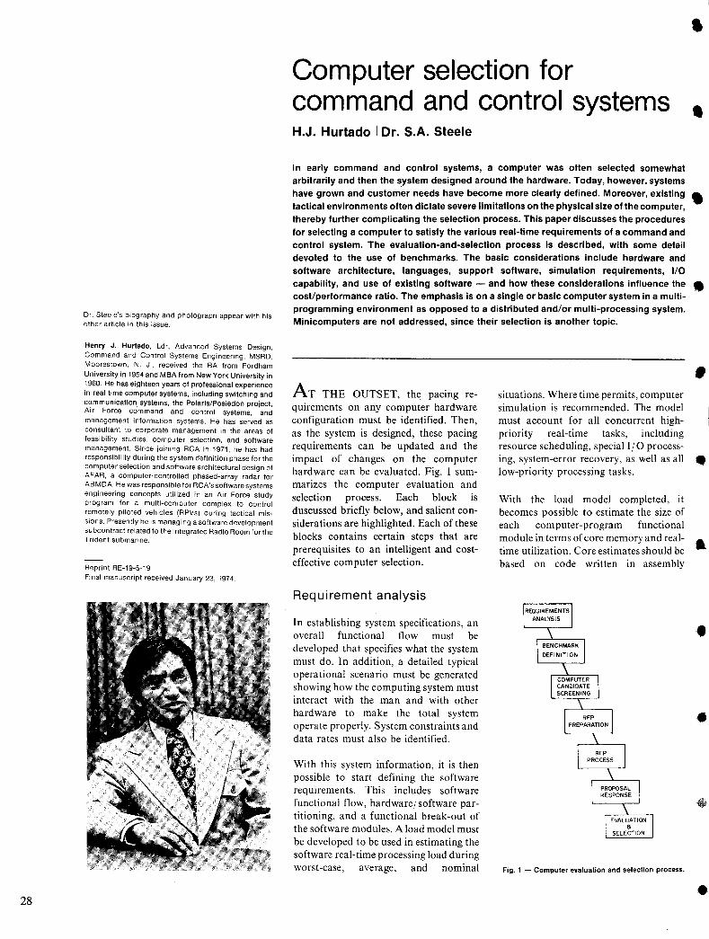
28
Dr. Steele's biography and photograph appear with his other article in this issue.
Henry J, Hurtado, Ldr, Advanced Systems Design, Command and Control Systems Engineering, MSRD, Moorestown, N. J., received the BA from Fordham University in 1954 and MBA from New York University in 1960. He has eighteen years of professional experience in real time computer systems, including switching and communication systems, the Polaris/Posiedon project, Air Force command and control systems, and management information systems. He has served as consultant to corporate management in the areas of feasibility studies, computer selection, and software management. Since joining RCA in 1971, he has had responsibility during the system definition phase for the computer selection and software architectural design of AFAR, a computer-controlled phased-array radar for ABMDA. He was responsible for RCA's software systems engineering concepts utilized in an Air Force study program for a multi-computer complex to control remotely piloted vehicles (RPVs) during tactical missions. Presently he is managing a software development subcontract related to the I ntegrated Radio Room for the Trident submarine.
Reprint RE-19-5-19 Final manuscript received January 23, 1974.
Computer selection for command and control systems H.J. Hurtado I Dr. S.A. Steele
In early command and control systems, a comp'Jter was often selected somewhat arbitrarily and then the system designed around the hardware. Today, however, systems have grown and customer needs have become more clearly defined. Moreover, existing tactical environments often dictate severe limitations on the physical size of the computer, thereby further complicating the selection process. This paper discusses the procedures
•
•
• for selecting a computer to satisfy the various real-time requirements of a command and control system. The evaluation-and-selection process is described, with some detail devoted to the use of benchmarks. The basic considerations include hardware and software architecture, languages, support software, simulation requirements, 1/0 capability, and use of existing software - and how these considerations influence the • cost/performance ratio. The emphasis is on a single or basic computer system in a multiprogramming environment as opposed to a distributed and/or multi-processing system. Minicomputers are not addressed, since their selection is another topic.
AT THE OUTSET, th~ pacing requirements on any computer hardware configuration must be identified. Then, as the system is designed, these pacing requirements can be updated and the impact of changes on the computer hardware can be evaluated. Fig. I summarizes the computer evaluation and selection process. Each block is duscussed briefly below, and salient considerations are highlighted. Each of these blocks contains certain steps that are prerequisites to an intelligent and costeffective computer selection.
Requirement analysis
In establishing system specifications, an overall functional flow must be developed that specifies what the system must do. In addition, a detailed typical operational scenario must be generated showing how the computing system must interact with the man and with other hardware to make the total system operate properly. System constraints and data rates must also be identified.
With this system information, it is then possible to start defining the software requirements. This includes software functional flow, hardware/ software partitioning, and a functional break-out of the software modules. A load model must be developed to be used in estimating the software real-time processing load during worst-case, average, and nominal
situations. Where time permits, computer simulation is recommended. The model must account for all concurrent highpriority real-time tasks, including resource scheduling, special I/O processing, system-error recovery, as well as all low-priority processing tasks.
With the load model completed, it becomes possible to estimate the size of each computer-program functional module in terms of core memory and realtime utilization. Core estimates should be based on code written in assembly
Fig. 1 - Computer evaluation and selection process.
•
•
•
•
•
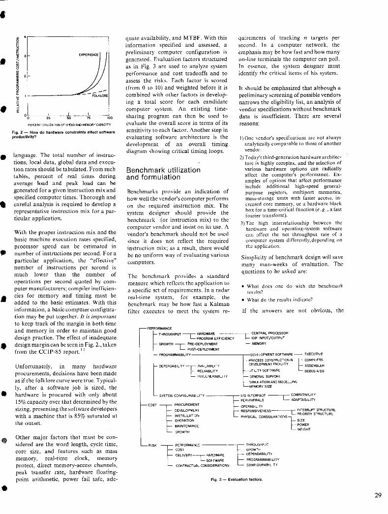
• ,
•
•
•
•
•
•
•
z 4,.-------------~ o g I!: !!1 3
" § '" z i :IE .. a:
'" o a: a.
"' > ~ ..J
"' a: °O~--~2L5--~~--~--~IOO
PERCENT UTIliZATION OF SPEED AND MEMORY CA~CITY
Fig. 2 - How do hardware constraints affect software productivity?
language. The total number of instructions, local data, global data and execution rates should be tabulated. From such tables, percent of real times during average load and peak load can be generated for a given instruction mix and specified computer times. Thorough and careful analysis is required to develop a representative instruction mix for a particular application.
With the proper instruction mix and the basic machine execution rates specified, processor speed can be estimated in number of instructions per second. For a particular application, the "effective" number of instructions per second is much lower than the number of operations per second quoted by computer manufacturers; compiler inefficiencies for memory and timing must be added to the basic estimates. With this information, a basic computer configuration may be put together. It is important to keep track of the margin in both time and memory in order to maintain good design practice. The effect of inadequate design margin can be seen in Fig. 2., taken from the CCIP-85 report. 1.2
Unfortunately, in many hardware procurements, decisions have been made as if the folklore curve were true. Typically, after a software job is sized, the hardware is procured with only about 15% capacity over that determined by the sizing, presenting the software developers with a machine that is 85% saturated at the outset.
Other major factors that must be considered are the word length, cycle time, core size, and features such as mass memory, real-time clock, memory protect, direct memory-access channels, peak transfer rate, hardware floatingpoint arithmetic, power fail safe, ade-
quate availability, and MTBF. With this information specified and assessed, a preliminary computer configuration is generated. Evaluation factors structured as in Fig. 3 are used to analyze system performance and cost tradeoffs and to assess the risks. Each factor is scored (from 0 to 10) and weighted before it is combined with other factors in developing a total score for each candidate computer system. An existing timesharing program can then be used to evaluate the overall score in terms of its sensitivity to each factor. Another step in evaluating software architecture is the development of an overall timing diagram showing critical timing loops.
Benchmark utilization and formulation
Benchmarks provide an indication of how well the vendor's computer performs on the required instruction mix. The system designer should provide the benchmark (or instruction mix) to the' computer vendor and insist on its use. A vendor's benchmark should not be used since it does not reflect the required instruction mix; as a result, there would be no uniform way of evaluating various computers.
The benchmark provides a standard measure which reflects the application to a specific set of requirements. In a radar real-time system, for example, the benchmark may be how fast a Kalman filter executes to meet the system re-
PERFORMANCE
THROUGHPUT ---c:: ~:~::=EEFFICIENCY GROWTH ..,-- PRE-OEPLOYMENT
L POST-DEPLOYMENT
quirements of tracking n targets per second. In a computer network, the emphasis may be how fast and how many on-line terminals the computer can poll. In essence, the system designer must identify the critical items of his system.
It should be emphasized that although a preliminary screening of possible vendors narrows the eligibility list, an analysis of vendor specifications without benchmark data is insufficient. There are several reasons:
I) One vendor's specifications are not always analytically comparable to those of another vendor.
2) Today's third-generation hardware architecture is highly complex, and the selection of various hardware options can radically affect the computer's performance. Examples of options that affect performance include additional high-speed generalpurpose registers, multi port memories, mass-storage units with faster access, increased core memory, or a hardware black box for a time-critical function (e.g., a fast fourier transform).
3) The high interrelationship between the hardware and operating-system software can affect the net throughput rate of a computer system differently, depending on the application.
Simplicity of benchmark design will save many man-weeks of evaluation. The questions to be asked are:
• What does one do with the benchmark results?
• What do the results indicate?
If the answers are not obvious, the
E CENTRAL PROCESSOR lOP INPUT/OUTPUT
MEMORY
PROGRAMMABILITY ---------,--DEVELOPMENT SOFTWARE 1 EXECUTIVE
PROCESS CONSTRUCTION a COMPILERS
DEPENDABILITY t AVAILABILITY DEVELOPMENT FACILITY ASSEMBLER
RELIABILITY UTILITY SOFTWARE DEBUG AIDS
INVULNERABILITY GENERAL SUPPORT
SIMULATION AND MODELLING MEMORY SIZE
PERIPHERALS ADAPTABILITY SYSTEM CONFIGURABILITY ~ 1/0 INTERFACE --~L'- COMPATIBILITY
COST ~ PROCUREMENT OPERABILITY
§ DEVELOPMENT RESPONSIVENESS L INTERRUPT STRUCTURE
RISK
PRIORITY STRUCTURE
OPERATION SIZE INSTALLATION PHYSICAL CONSIDERATIONS 1= MAINTENANCE POWER
WEIGHT GROWTH
1 PERFORMANCE --------,r- THROUGHPUT
COST GROWTH
DELIVERY-,- HARDWARE DEPENDABILITY
L SOFTWARE PROGRAMMABILITY
CONTRACTUAL CONSIDERATIONS CONFIGURABILITY
Fig. 3 - Evaluation factors.
29
30
benchmark is not properly designed.
Among the several technical factors essential for an adequate benchmark, four major considerations affect the computer configuration:
I) Inputl output throughput: the rate at which the computer channels can get data in and out of the machine. Is the data rate so high that cycle stealing is inadequate and requires a multi port memory?
2) Processor logic and arithmetic: the computational capability and range of processing. For example, is floating-point.doubleprecision required? Can software routines substitute for hardware mUltiply I divide? Is emulation required?
3) Data storage: the type and volume of data storage. Is random access required or can magnetic storage be adequate?
4) Operating-system software: an integrating element for the above three factors which ultimately reflects how well the computer makes use of its resources.
Unless the system designer plans to develop a specially tailored operating system for an end use, the benchmark should include operating-system performance. In past real-time systems, it has been necessary for computer users to write parts of their operating system. In these situations, a system designer may consider modifying the vendor's operating system rather than developing a new one. The development of a new operating system is expensive and generally requires a long-lead implementation schedule.
A product of any benchmark is evaluation of the compiler. An inefficient compiler may cost excessive computer time and additional core storage. A compiler must be evaluated both from a development and production standpoint: that is, compile time and execute time.
Two benchmark models have been useful in computer evaluation; these models address the technical factors and application considerations mentioned above.
Benchmark 1
The first model (Benchmark I) provides a standard program that can be used by all computer vendors. It is written in a compiler language (FORTRAN or COBOL) and addresses the highly critical function(s), which may be a worst-case situation or a representative example of a major processing load. In one radar system, for example, this program was a
fully coupled Kalman filter, written in FORTRAN. This model provides the following advantages:
I) It is written in FORTRAN. giving all vendors a standard program.
2) It demonstrates the compiler capabilities and whether the vendor's FORTRAN compiler is at a specified standard level.
3) It outlines the computer configuration necessary to support that program.
4) It provides core estimates and compilation times.
5) It allows a demonstration of debugging aids and their capability in software development.
6) It provides core estimates and running time in executing the program.
Benchmark 2
The second model (Benchmark 2) is a program specification that permits the vendor to demonstrate the capability of his computer hardware and the overhead associated with the operating system. The model has two elements: the first is a basic processor task (no I/O) and ti:Je second is the execution of the same basic processor task under increasing rates of I/O and interrupt activity.
The basic processor task(s) may be to exercise certain highly used instructions (e. g ., shift instructions, move instructions, bit/ byte manipUlation, doubleprecision). The processor task should be written in the language that will ultimately be used. In real-time processing, the task might be written in assembly language.
The processor task may be short but can be executed repetitively and long enough to get an accurate time measurement. For example, a routine that can execute in 600 f.1.S is too short if the internal clock has only a millisecond resolution. However, if it is executed 1000 times, then the measurement of 600 ms ± clock variance is meaningful. Timing should be provided for each task in the case where several tasks are used as the processing baseline.
The second part of this model performs the same task(s) but is interrupted by I/O and hardware/ software interrupts. There are several stages, where each stage runs the processor tasks but interrupts at a certain rate (e. g. , every lOOms, 50ms and Ims). This allows the user to see the amount of operating system overhead required to service I/O and interrupt requests. As the rate increases, a good operating system will show no ap-
preciable degradation.
Variations of this model can be developed to measure the operating effectiveness of sequential files, random files, and indexsequential files. The model can also be set up to show the effect of mUltiple I I 0 requests to the same data base.
The advantages of this second model are as follows:
I) The vendor can write a program task utilizing the best features of his system.
2) The user is given definite time statistics on system overhead.
3) The user can see whether cycle-stealing for 110 can severely affect processing time.
4) The points where interrupts can degrade the system are highlighted.
Comparative analysis
I t is interesting to note the credibility of these benchmarks compared with the vendor's specification and other benchmarks which had the same candidate computers.
The first comparative evaluation used for radar application is on three processors supplied by different computer vendors. Table I shows some of the basic computer characteristics of three machines. At first glance, processor A looks more powerful; however, the benchmark results of the two models shown in Table II do not substantiate first impressions. Benchmark I which was the FORTRAN Kalman filter (basically a number crunching routine) proved processor C to be twice as fast as A. In benchmark 2, processor B showed its low operating system overhead as the interrupt rate increased. In fact, the I-ms interrupt caused processor C processing time to rapidly increase, and processor A failed to provide any timing data.
Comparing these results against other benchmark studies, we find somewhat similar results among the same family line of computers. The Philco-Ford Study3 by J. Corsiglia also shows processor B as the most cost-effective machine over processor A and processor C.
RFP preparation and evaluation Referring to the process outlined in Fig. I, with the basic configuration and benchmarks defined, it is now possible to screen and identify various computer candidates and to develop specific
•
•
•
•
•
•
•
•
•
•
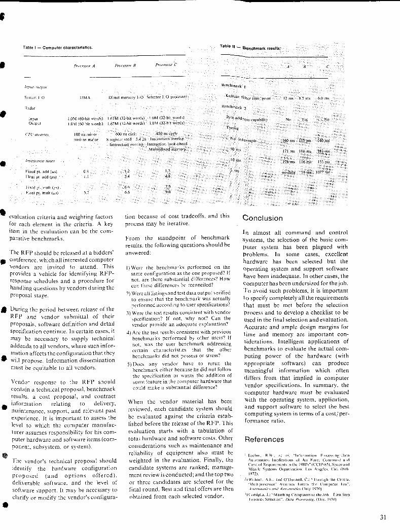
• Table I - Computer characteristics. Table II - Senchmark resuUs. --• ProceS50r A Processor B Processor C A B C ----JIIIJU{' outpU! Benchmark I
S~stcm 1'0 D\1A Direct memory I iO Selector I/O processor Kalman filter time/point 12 ms 8.5 ms 6.0 ms
Radar Benchmark ~
Input Output
1.0M (60-bit words) 1.67M (32-bit words) 1.0M (32-bit words) 1.0M (60-bit words) 1.67M (32-bit words) 1.0M (32-bit words)
Byte address capability No Yes No
Ti!l1ing
CPU memory 100 ns minor 600 ns cycle 850 ns cycle 1000 os major 8 register load--5A f.LS Instruction overlap
Instruction overlap Instruction look~ahead Multiplexed memory
No. interrupts 160 ms liS ms 140 ms
•
•
IllsTrunian limes
Fixed pI. add (Jis) 0.8 Float pI. add (Jis) 1.1
Fixed pc mult (Jis) Hoal pc mull (Jis) 5.7
evaluation criteria and weighting factors for each element in the criteria. A key item in the evaluation can be the comparative benchmarks.
The RFP should be released at a bidders' • conference, which all interested computer
vendors are invited to attend. This provides a vehicle for identifying RFPresponse schedules and a procedure for handling questions by vendors during the proposal stage.
• During the period between release of the RFP and vendor submittal of their proposals, software definition and detail specification continue. In certain cases, it may be necessary to supply technical addenda to all vendors, where such infor-
• mation affects the configuration that they will propose. Information dissemination must be equitable to all vendors.
Vendor response to the RFP should contain a technical proposaL benchmark results, a cost proposal, and contract
• information relating to delivery, maintenance, support. and relevant past experience. It is important to assess the level to which the computer manufacturer assumes responsibility for his computer hardware and software items (component, subsystem, or system).
•
•
The vendor's technical proposal should identify the hardware configuration proposed (and options offered). deliverable software. and the level of software support. It may be necessary to clarify or modify the vendor's configura-
50 ms
1.2 2.4
6.6
6.6
1.7 4.8
7.5 9.0
tion because of cost tradeoffs, and this process may be iterative.
From the standpoint of benchmark results, the following questions should be answered:
I) Were the benchmarks performed on the same configuration as the one proposed? If not. arc there substantial differences? How can these differences be reconciled?
2) Were all listings and tcst data output verified to ensure that the benchmark was actually performed according to user specifications')
3) Were the test results consistent with vendor specification'? If not, why not? Can the vendor provide an adequate explanation'?
10 ms
1m.
4) Are the test results consistent with previous benchmarks performed by other users') If not, was the user benchmark addressing certain characteristics that the other benchmarks did not possess or stress?
5) Does any vendor have to rerun the benchmark either because he did not follow the specification or wants the addition of some feature in the computer hardware that could make a substantial difference'?
When the vendor material has been reviewed, each candidate system should be evaluated against the criteria established before the release of the RFP. This evaluation starts with a tabulation of total hardware and software costs. Other considerations such as maintenance and reliability of equipment also must be weighted in the evaluation. Finally, the candidate systems are ranked; management review is conducted; and the top two or three candidates are selected for the final round. Best and final offers are then obtained from each selected vendor.
171 ms 116 ms 141 ms
176 ms 116 ms 153 ms
no data 123 ms 1077 ms
Conclusion
In almost all command and control systems, the selection of the basic comPuter system has been plagued with Problems. In some cases, excellent hardware has been selected but the operating system and support software have been inadequate. In other cases, the computer has been undersized for the job. 10 avoid such problems, it is important to specify completely all the requirements that must be met before the selection process and to develop a checklist to be used in the final selection and evaluation. Accurate and ample design margins for time and memory are important considerations. I ntelligent applications of benchmarks to evaluate the actual computing power of the hardware (with appropriate software) can produce meaningful information which often differs from that implied in computer vendor specifications. In summary, the computer hardware must be evaluated with the operating system, application, and support software to select the best computing system in terms of a cost/ performance ratio.
References
! Boehm, H.W.: e( al: "Information Processing Data I\utomation Implications of Air Force Command and Cl~nt.rol Requirements in the 1980's" (CCIP-8S). Space and M ISStiC Systems Organization, Los Angeles. Cal. (Feb. 1972).
2) William, A.E.: and O'Donnell, c.: "Through the Central 'Multiprocessor' Ayionics Enters the Computer Era", ,fsUollaulics and Aeronautics (July 1970).
.I) Corsiglia. J.: "Matching Computers to the Job First Step I awards Selection", Data Processing. (Dec. 1970).
31
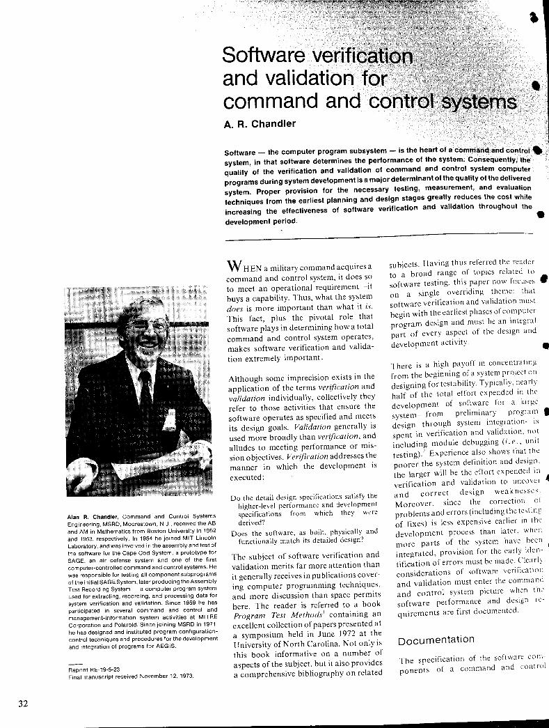
32
Alan R. Chandler. Command and Control Systems Engineering, MSRD, Mooreslown, N.J., received the AB and AM in Mathematics from Boston University in 1952 and 1953, respectively. In 1954 he joined MIT Lincoln Laboratory, and was involved in the assembly and test of Ihe software for the Cape Cod System, a prolotype for SAGE, an air defense system and one of the first com puler-controlled command and control systems. He was responsible for testing all component subprograms of the initial SAGE System, later producing the Assembly Test Recording System - a computer program system used for extracting, recording, and processing data for system verification and validation. Since 1959 he has participated in several command and control and management-information system activities at MITRE Corporation and Polaroid. Since joining MSRD in 1971, he has designed and instituted program configurationcontrol techniques and procedures for the development and integration of programs for AEGIS.
Reprint RE-19-5-23 Final manuscript received November 12, 1973.
, Software verificati and validation for command and control • A. R. Chandler
Software - the computer program subsystem - is the heart of a command and control. system, in that software determines the performance of the system. Consequently, the quality of the verification and validation of command and control system computer programs during system development is a major determinant of the quality of the delivered system. Proper provision for the necessary testing, measurement, and evaluation techniques from the earliest planning and design stages greatly reduces the cost while increasing the effectiveness of software verification and validation throughout the
development period. •
W HEN a military command acquires a command and control system, it does so to meet an operational requirement-it buys a capability. Thus, what the system does is more important than what it is. This fact, plus the pivotal role that software plays in determining how a total command and control system operates, makes software verification and validation extremely important.
Although some imprecision exists in the application of the terms verification and validation individually, collectively they refer to those activities that ensure the software operates as specified and meets its design goals. Validation generally is used more broadly than verification, and alludes to meeting performance or mission objectives. Verification addresses the manner in which the development is executed:
Do the detail design specifications satisfy the higher-level performance and :levelopment specifications from which they were derived?
Does the software, as built, physically and functionally match its detailed design')
The subject of software verification and validation merits far more attention than it generally receives in publications covering computer programming techniques, and more discussion than space permits here. The reader is referred to a book Program Test Methods l containing an excellent collection of papers presented at a symposium held in June 1972 at the University of North Carolina. Not only is this book informative on a number of aspects of the subject, but it also provides a comprehensive bibliography on related
subjects. Having thus referred the reader to a broad range of topics related to software testing, this paper now focuses • on a single overriding theme: that software verification and validation must begin with the earliest phases of computer program design and must be an integral part of every aspect of the design and development activity. • There is a high payoff in concentrating from the beginning of a system project on designing for testability. Typically, nearly half of the total effort expended in the development of software for a large system-from preliminary program" design through system integration IS
spent in verification and validation. not including module debugging (i. e., unit testing).2 Experience also shows that the poorer the system definition and design. the larger will be the effort expended in verification and validation to uncover • and correct design weaknesses. Moreover. since the correction 01 pro blems and errors (including the testi ng of fixes) is less expensive earlier in the development process than later. when more parts of the system have been integrated, provision for the early idcn- 41 tification of errors must be made. Clearly considerations of software verification and validation must enter the command and control system picture when the software performance and design requirements are first documented.
Documentation
The specification of the software components of a command and control
• system begins with the "system s?ecification." This specification descnbes the system performance requirement.s and objectives, as well as the ~llocatlOn of
• functions within these reqUirements and objectives to the major system items, including the computer programs. T~e system specification is used as the basIs for the computer program performance specifications (variously called "development" or "Part I" specifications). These specifications set forth function~1 requirements and system. constralllts~ predefined items such as Illterfaces and existing equipment that affect program performance.
• The details of program organization (such as the specific modules, or the ?~ta files), other than the use of speCified algorithms, equations, customerfurnished executive programs, and the like are described in the computer
, design specifications (or program "product" or "Part II" specifications). Thus the performance specificatIOns prescribe what the pr~gram is to ~o, whereas the design speCificatIOns specify how it is to be built.
Although the specific specifications a~~ .• related documents (the "document tree)
may vary from system to system, and from user to user, they generally take on the characteristics just described. Of particular note is that these documents form the only basis for test planm.ng ~nd
• the actual verification and vahdatl~n process. To form an adequate b~SIS,
therefore, each specification descnbes not only the requirements for the program, but also the provisions for quality assurance~the approac~ to review, testing, test tools and t.echmques
• to be - used, facilities reqUired, and tolerances and pass-fail criteria to be a plied to the specified requirements. All pianning for software verification and validation is governed by the fact t~at t?e system can be certified as meetlllg Its
•
•
functional requirements when and only when the specified quality assurance provisions have been met.
Test planning
Planning for software verification and validation is intimately related ~o development planning, and proceeds III
parallel with it. The software development plan covers the entire process from coding and debugging the modules or "units" through building packages of
. ntegrating the major modules and ~s including at least a software elem
en ~al system integration
Portion of the. tOes this plan is called the Someum process.
"build" plan.
vides the basis for The test plan pr:chievement o.f the measuring the he build plan, III the milestones of ;nware quality assurance
text of the s. test plan cannot be con ThiS . I t
rovisions. . to software Imp emen a-p mpleted pnor ecific programs pro-co the sp 'f' . . since h design speci !CatIOns tiOn, . fy t e ., d
d d to saUS pecifled III a vance~ uce '1 not s I . I de detal s . ation, code va ues, mc u gamZ ..
'Is of or eture~whlch dictate detal d strU S· '1
a tion, an unning a test. Iml ar-oper for r . h roeedures I used~test dnvers, tep taOS '11
the test generators-wI not l~, lators, test da
dta
when the first test Slmu de . h have been CO lace. Accordlllgly, t e
I nning takes dP ced in stages, and IS p a . ro u h' h t plan IS p t procedures, w IC tesgmented by tesde names, equipment au lude specific cOd setups, personnel re-Inc . an
nfiguratiOnS . required test outputs, co cnpts, I . 'rements,s t plan appears ear y III qUi .. I teS .
etc. The inlua nt process, but plannlllg h develop me test plan documents are ted the f h t tinues an dated as a part 0 t a con d and up controlle process.
ment progresses and As the develoP oftware system are
f the s . lements 0 t plannmg can be ac-e it tes .
d signed, un . not possible to an-edIt IS . h
mplishe . equirements, smce t e co 't test r 'f" d . 'pate um design speci IcatlOns 0 UCI nd ..
rformance a '1 d module (umt) deSign pe detal e . h t provide 'nce it is essential t at
ndot However, Sl roceed in a controlled a a. ss P h build proee must be given that the t e nee .
f hion, assura have been completely as dules . . ftware mo their aggregatIOn mto so . ta 'f' d pnor ven Ie es
larger paekag .
design Software
mmand and control of CO .. th The design eSS of organIZIng e Proe .
StemS is a tions that the system IS sy f fu ne 'b d h· archy 0 tl'sfying the prescn e ler . sa t perform In ·rements. From the mao rational requlbfunctions are derived
ope . sU . I I . functiOnS, stitute the hlgher- eve Jor con .
h· h together rocess is repeated m w IC ThiS P . f tions. hical levels-the mter-unc . rare b .
essive hie mon tasks, etc., emg succ corn connections, h level.
d t eae define a .
. functional analysIs at Th level of thiS e allocated to the prime
e ks ar h· h the taS w IC
elements of the system-equipment, software, people~is the basis for the software performance specifications. These in turn become the basis for the design requirements and the design itself.
Before coding of the system software can begin, an effective software structure must have been derived, and the detailed design of each software element (program modules, data files, special subroutines, executive programs) must have been accomplished. In most command and control system programs, there is an "executive" program, responsible for keeping track of what is going on, what devices are in Use or available for use, and what modules are scheduled for operation. There are also service routines, shared by many modules, for controlling attached equipment and for performing standard mathematical and datamanagement functions.
Each of these many components is designed to accept certain specified inputs~variables and parameters-and to generate certain outputs. These inputs and outputs may be passed directly between modules or may be held in buffers or data files for later processing. It is here that verification and validation enter the picture: These inputs and outputs are the "stimuli" and "responses" of each element, and the assurance that an element or "unit" yields the proper responses to prescribed stimuli constitutes unit test and verification. Effective testability dictates that provision be made in the original layout of the elements for setting the test conditions and data inputs, and for extracting and reporting the reSUlts. If such provision is not made in initial design, data which could be very important for verification could be lost or overwritten by subsequent calculations. For example, intermediate results can yield clues as to the source of computation errors.
At the level of modUle or element design and coding, a valuable technique is now available called structured programming; this is a concept that has only recently achieved maturity and recognition. 3 As applied to verification and validation, this design approach not only simplifies coding and hence provides more accurate initial code, but it also carries the "stimulus-response" aspect of testing to the lowest levels of the software system. Following the structured programming approach, the programmer first codes the
33
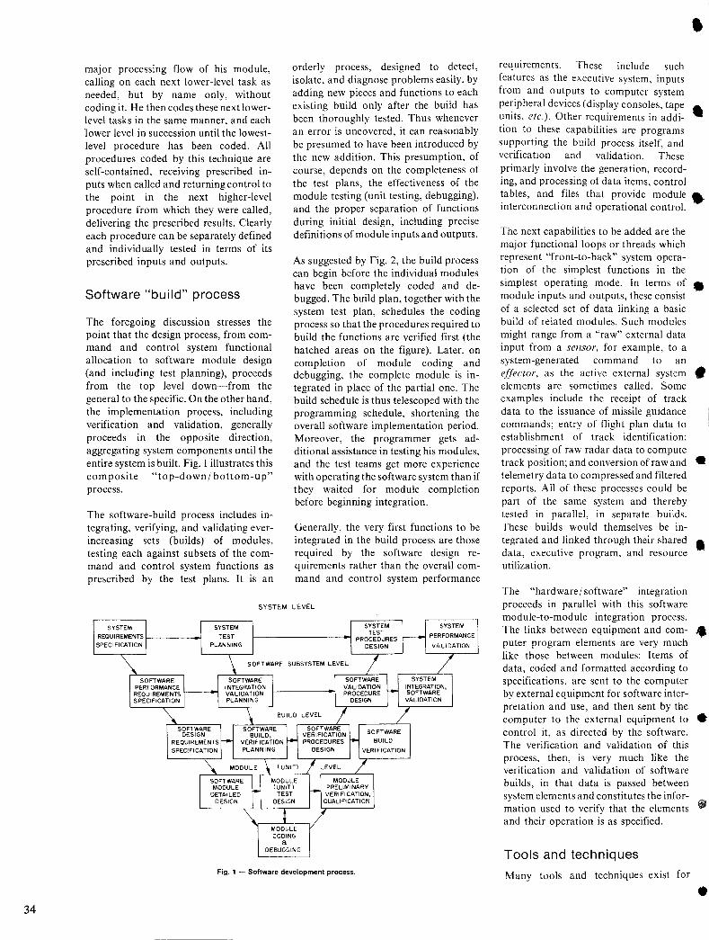
34
major processing flow of his module, calling on each next lower-level task as needed, but by name only, without coding it. He then codes these next lowerlevel tasks in the same manner, and each lower level in succession until the lowestlevel procedure has been coded. All procedures coded by this technique are self-contained, receiving prescribed inputs when called and returning control to the point in the next higher-level procedure from which they were called, delivering the prescribed results. Clearly each procedure can be separately defined and individually tested in terms of its prescribed inputs and outputs.
Software "build" process
The foregoing discussion stresses the point that the design process, from command and control system functional allocation to software module design (and including test planning), proceeds from the top level down-from the general to the specific. On the other hand, the implementation process, including verification and validation, generally proceeds in the opposite direction, aggregating system components until the entire system is built. Fig. I illustrates this composite "top-down/ bottom-up" process.
The software-build process includes integrating, verifying, and validating everincreasing sets (builds) of modules, testing each against subsets of the command and control system functions as prescribed by the test plans. It is an
orderly process, designed to detect, isolate, and diagnose problems easily, by adding new pieces and functions to each existing build only after the build has been thoroughly tested. Thus whenever an error is uncovered, it can reasonably be presumed to have been introduced by the new addition. This presumption, of course, depends on the completeness of the test plans, the effectiveness of the module testing (unit testing, debugging), and the proper separation of functions during initial design, including precise definitions of module inputs and outputs.
As suggested by Fig. 2, the build process can begin before the individual modules have been completely coded and debugged. The build plan, together with the system test plan, schedules the coding process so that the procedures required to build the functions are verified first (the hatched areas on the figure). Later, on completion of module coding and debugging, the complete module is integrated in place of the partial one. The build schedule is thus telescoped with the programming schedule, shortening the overall software implementation period. Moreover, the programmer gets additional assistance in testing his modules, and the test teams get more experience with operating the software system than if they waited for module completion before beginning integration.
Generally, the very first functions to be integrated in the build process are those required by the software design requirements rather than the overall command and control system performance
SYSTEM LEVEL
Fig. 1 - Software development process.
• requirements. These include such features as the executive system, inputs from and outputs to computer system peripheral devices (display consoles, tape ... units, etc.). Other requirements in addi- • tion to these capabilities are programs supporting the build process itself, and verification and validation. These primarly involve the generation, recording, and processing of data items, control tables, and files that provide module • interconnection and operational control.
The next capabilities to be added are the major functional loops or threads which represent "front-to-back" system opera-tion of the simplest functions in the simplest operating mode. In terms of • module inputs and outputs, these consist of a selected set of data linking a basic build of related modules. Such modules might range from a "raw" external data input from a sensor, for example, to a system-generated command to an effector, as the active external system • elements are sometimes called. Some examples include the receipt of track data to the issuance of missile guidance commands; entry of flight plan data to establishment of track identification; processing of raw radar data to compute track position; and conversion of raw and • telemetry data to compressed and filtered reports. All of these processes could be part of the same system and thereby tested in parallel, in separate builds. These builds would themselves be integrated and linked through their shared • data, executive program, and resource utilization.
The "hardware/ software" integration proceeds in parallel with this software module-to-module integration process. The links between equipment and com- .. puter program elements are very much like those between modules: Items of data, coded and formatted according to specifications, are sent to the computer by external equipment for software interpretation and use, and then sent by the computer to the external equipment to • control it, as directed by the software. The verification and validation of this process, then, is very much like the verification and validation of software builds, in that data is passed between system elements and constitutes the information used to verify that the elements ,. and their operation is as specified.
Tools and techniques
Many tools and techniques exist for
•
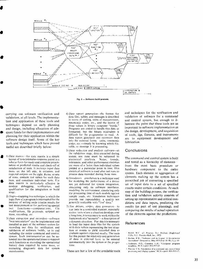
•
•
•
•
•
•
•
•
•
MODULE COOl NG 8 DEBUGGING
carrying out software verification and validation, at all levels. The implementation and application of these tools and techniques depend on early planning and design, including allocation of adequate funds for their implementation and planning for their application within the software design itself. Some of the key tools and techniques which have proved useful are described briefly below:
I) Dara marrix-the data matrix is a simple layout of tests (stimulus-response pairs) in a tabular form for ready and complete presentation of predicted results and check-off of satisfaction of tests. It portrays input data items on the left side, in columns, and required outputs on the right. Rows, or sets of rows, contain test values for each data item, and constitute individual tests. The data matrix is particularly effective in module debugging, verification, and qualification for the integration or build stage.
2) Traps-trapping is a technique in which the logic flow of a program is interrupted for the purpose of setting aside interim results for test measurement or for performing special test functions-computations, file modifications, file printouts, scripted actions, recording, etc.
3) Data exrraction and recording-software "instrumentation" can be implemented and installed as part of the software system for recording test data for verification and validation of software builds, up to and including the entire command and control system. Such instrumentation can be extended into the operational phase to support such functions as recording the operational history data required by some users, or extracting diagnostic data for system maintenance.
1 BUILDING 8 VERIFICATION
Fig. 2 - Software-build process.
4) Dara reporr generarion-the format for data files, tables, and messages is described in terms of scaling, units of measurement, mnemonic codes, etc., and the layout of these values in binary computer "words." Programs are coded to handle this data as formatted, but the binary equivalent is difficult for the programmer to read. A data report generator can reconvert data into the external forms-units, mnemonic codes, erc.-simply by knowing which file, table, or message it is processing.
5) Dara reduction and analysis so/iware-at the validation stage, data extracted during system test runs must be SUbjected to statistical analysis. Noise, trends, tolerances, and other performance statistics are more of a factor than individual values yielded at a particular point in time. This statistical software is used after test runs to process data recorded during those runs.
6) Simulators-simulation is a technique used for modeling the performance of a device not yet delivered for system integration, simulating only its software interfaces, modeling the environment, simulating only the processing time of each module against sample loads, etc. Simulation techniques provide test repeatability, a quality not generally realizable with "Jive" data:
7) Tesr drivers, scripts. data generarors"~to run tests in a controlled manner, especially system tests where a situation develops over a long time, it is necessary to work within the framework of a "scenario"-a description of a dynamic situation. For this it is necessary to load the input data files for the system with data values representing the test situation or events to yield recorded data to evaluate against expected results. The tools for this permit the relatively easy generation of data in external form to be entered automatically into the system at the proper time.
These are but a few of the available tools
I [NTEGRATION 8 VAL IDATION
and techniques for the verification and validation of software for a command and control system, but enough to illustrate the point that these tools are as important to software implementation as the design, development, and acquisition of tools, jigs, fixtures, and instruments are to equipment development and fabrication.
Conclusions
The command and control system is built and tested as a hierarchy of elementsfrom the most basic procedure or hardware component to the entire system. Each element or aggregation of elements making up the system has a prescribed job of converting a specified set of input data to a set of specified results under certain conditions. At each step of the building process, the verification and validation activity consists of setting up representative and critical conditions and data inputs, predicting the results (as part of test planning), and comparing the results of actual operation of the elements against the predictions.
References
I. Hetzel. W.C" ed: Proxram Test Methods (Englewood Cliffs. ~.J .. Prentice-Hall. Inc., 1973
2. Boehm. B.W.; "Software and its Impact: A Quantitative Assessment" Datamation. May 1973 (Vol. 19. No.5,) p. 49
J. Anderson. P.G.; Crandon, L.H.: "Computer program reliability, RCA reprint RE-19-5-21.
4. Warren. C.S.: Simulation of a command and control data processing and display system." RCA reprint RE-19-5-17.
35
36
Stu Warren, Aerospace Systems Division, Burlington, Mass. received the BSEE in 1952 from Virginia Polytechnic Institute. He joined RCA in 1952 as an engineer on the Specialized Training Program, following which he spent seven years in applied research working on magnetic memory devices. Also during this period, he was responsible for the design of several memory systems used in BMEWS. In 1959, Mr. Warren was transferred to the Van Nuys Division of RCA where he headed a logic design group and was responsible for the design of a small real-time computer used in the MIPIR instrumentation radar. In 1963, Mr. Warren joined the Computer Systems Division where he was responsible for the emulators used in the Spectra 70 product line. In 1970 Mr. Warren moved to the RCA Marlboro plant where he participated in the development of a new product line of processors. In 1972 Mr. Warren transferred to his current position as Staff Engineering Scientist at ASD where he has participated in several major proposal, efforts for both Command and Control and the Space Shuttle. Mr. Warren is a member of the ACM, Eta Kappa Nu, and author of several papers and patents.
Reprint RE-19-5-17
Final manuscript received November 26, 1973.
• Simulation of a command and control data processing and display system C. S. Warren
• System simulation can be used to verify that a proposed hardware / software configuration for a command and control system will have the needed throughput and response times at peak load. Recently, a system Simulator was developed to be used in determining the throughput and response-time capabilities of a data processing and display system for a
proposed Tactical Air Control Center Automation. The simulator specifically addresses • the hardware and software of the data processing subsystem. It shows the utilization of various hardware and softWare components of the data processing subsystem and keeps track of the lengths of all the subsystem queues, it exhibits the critical paths in the flow of data. The simulator also provides sensitivity tests to such parameters as CPU speed, assignment of priority, and various software features, thus allowing the system architect to evaluate alternative subsystem designs. The simulator is, therefore, a tool for use in system optimization as well as a means of performance verification. •
T HE SYSTEM being modeled consists of a central processor, a mass memory subsystem, a controller for all communication and display interfaces, the resident portions of the TDOS-IPS/70 software, an operational data base, and application software. The TDOS-IPS /70 software is a data-base management software system that was offered commercially by RCA Computer Systems, The simulation model is driven by input data supplied by the user in the form of operational scenarios, Each operational event in a -scenario is subdivided into transactions, one transaction for each operator action or input message, The individual transactions, scheduled in accordance with the scenario (allowing for human reaction-time to responses from the system), are the actual input to the simulator.
The outputs of the simulator consist of reports of the response time to each event in the scenario, statistical reports on response times to individual transactions, and statistical reports of the utilization of hardware and software components of the data processing and display (DP&D) system, All queues in the subsystem are monitored and their length statistics are reported, The statistics, which are reported periodically throughout the simulation, consist of the mean, the standard deviation, the maximum value,
and the minimum value of each variable.
The simulator is coded in Fortran and is • based on the general-purpose simulation program-GASP II. Most of the critical system parameters are provided as input data, and so can be varied without recompilation, The use of Fortran allows structural changes in the model (to in- • vestigate potential structural simplification in the DP&D system) with manageable effort.
Hardware
•• The hardware elements included in the model are shown in Fig, I. The central processor unit (CPU) is characterized by its speed (instructions/sec) and memory capacity. It could be any processor with simultaneous compute and input/ output (I/O) capability, The I/O devices • modeled include the mass memory and interface controller. The mass memory was assumed to interface the CPU thru a dual-channel controller permitting access to two records simultaneously, Drums were assumed in the model, but only modest modification would permit multi- .. pie disk files in place of the drums, The interface controller is the interface for all communication and display SUbsystems, The unit record peripherals (printers, card readers, etc.) normally associated
•
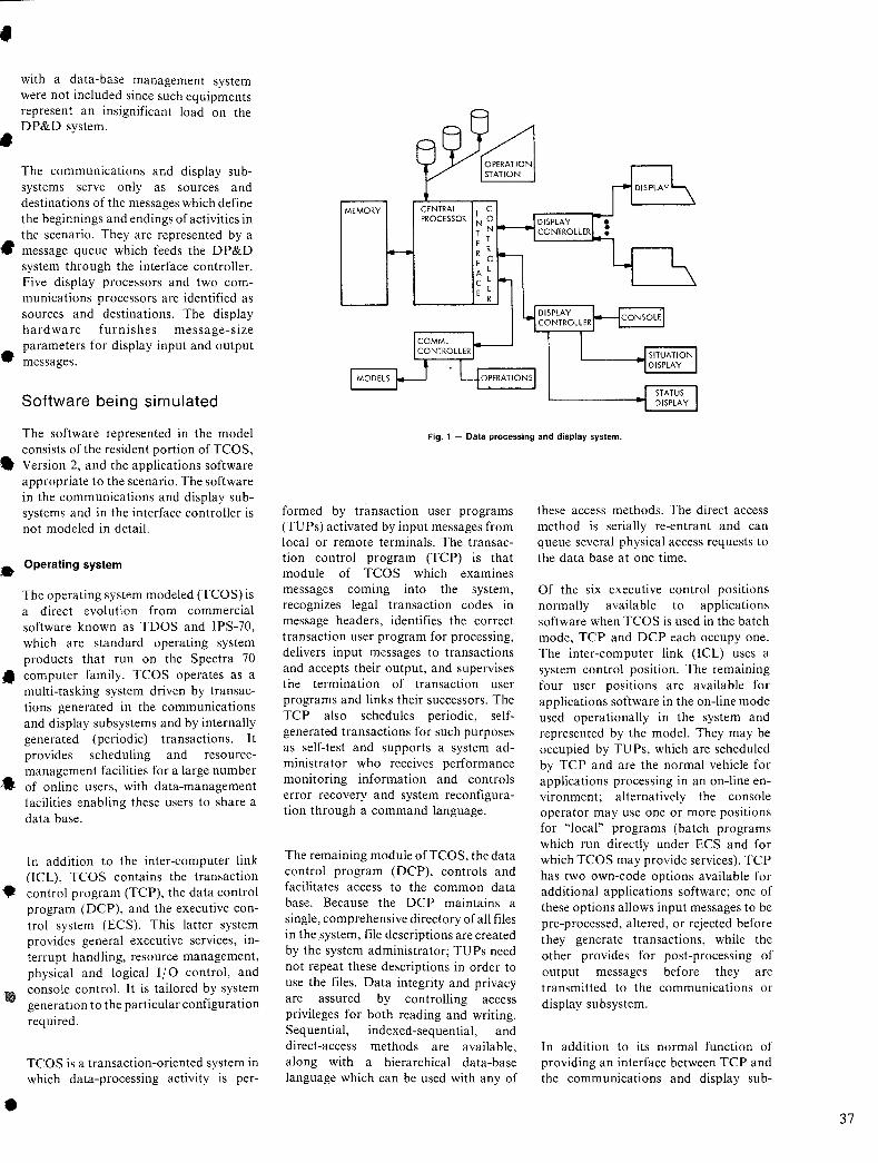
•
•
•
with a data-base management system were not included since such equipments represent an insignificant load on the DP&D system.
The communications and display subsystems serve only as sources and destinations of the messages which define the beginnings and endings of activities in the scenario. They are represented by a message queue which feeds the DP&D system through the interface controller. Five display processors and two communications processors are identified as sources and destinations. The display hardware furnishes message-size parameters for display input and output messages.
Software being simulated
The software represented in the model consists of the resident portion of TCOS,
• Version 2, and the applications software appropriate to the scenario. The software in the communications and display subsystems and in the interface controller is not modeled in detail.
• Operating system
The operating systp.m modeled (TCOS) is a direct evolution from commercial software known as TDOS and IPS-70, which are standard operating system products that run on the Spectra 70
• computer family. TCOS operates as a multi-tasking system driven by transactions generated in the communications and display subsystems and by internally generated (periodic) transactions. It provides scheduling and resourcemanagement facilities for a large number
... of online users, with data-management facilities enabling these users to share a data base.
In addition to the inter-computer link (lCL), TCOS contains the transaction
• control program (TCP), the data control program (DCP), and the executive control system (ECS). This latter system provides general executive services, in-
•
terrupt handling, resource management, physical and logical 1/0 control, and console control. It is tailored by system generation to the particular configuration required.
TCOS is a transaction-oriented system in which data-processing activity is per-
MEMORY CENTRAL PROCESSOR
Fig. 1 - Data processing and display system.
formed by transaction user programs (TUPs) activated by input messages from local or remote terminals. The transaction control program (TCP) is that module of TCOS which examines messages coming into the system, recognizes legal transaction codes in message headers, identifies the correct transaction user program for processing, delivers input messages to transactions and accepts their output, and supervises the termination of transaction user programs and links their successors. The TCP also schedules periodic, selfgenerated transactions for such purposes as self-test and supports a system administrator who receives performance monitoring information and controls error recovery and system reconfiguration through a command language.
The remaining module ofTCOS, the data control program (DCP), controls and facilitates access to the common data' base. Because the DCP maintains a single, comprehensive directory of all files in the system, file descriptions are created by the system administrator; TUPs need not repeat these descriptions in order to use the files. Data integrity and privacy are assured by controlling access privileges for both reading and writing. Sequential, indexed-sequential, and direct-access methods are available, along with a hierarchical data-base language which can be used with any of
these access methods. The direct access method is serially re-entrant and can queue several physical access requests to the data base at one time.
Of the six executive control positions normally available to applications software when TCOS is used in the batch mode, TCP and DCP each occupy one. The inter-computer link (lCL) uses a system control position. The remaining four user positions are available for applications software in the on-line mode used operationally in the system and represented by the model. They may be occupied by TU Ps, which are scheduled by TCP and are the normal vehicle for applications processing in an on-line environment; alternatively the console operator may use one or more positions for "local" programs (batch programs which run directly under ECS and for which TCOS may provide services). TCP has two own-code options available for additional applications software; one of these options allows input messages to be pre-processed, altered, or rejected before they generate transactions, while the other provides for post-processing of output messages before they are transmitted to the communications or display subsystem.
In addition to its normal function of providing an interface between TCP and the communications and display sub-
37
38
systems, the intercomputer link (ICL) carries out functional processing in connection with track-message reception and frag-order dissemination.
Prominent software modules
The software modules most significant in the operation of the simulation model are the Loader, the TCP, the TUP, the ICL, and the executive scheduler. Other functions of the ECS are accounted for by overheads added to the processing times of the programs supported by the ECS; the execution time ofthe DCP is similarly treated.
Loader: the Loader module handles the relocatable loading of the transaction user programs (TU Ps) when the transaction control program has committed system resources to a transaction and when an already resident program calls for a successor TU P. The Loader reads the directories which locate the program on the primary mass memory. Then it reads the text portion of the program, using as many physical accesses as are necessary. Finally the modifier portions of the TUP are read and are applied to the previously loaded portion of the program to adjust it to its load point. In the model, the correct number of physical accesses for each load is calculated from the specified size of the program being loaded, the loading of modifiers is simulated, and the execution time of the Loader code itself is simulated.
Transaction control program: the Transaction Control Program (TCP) converts incoming messages into transactions using a terminal directory list prepared by the system administrator. It determines which TU P in the program library should be the initial TU P to resolve the transaction request. If an ECS control position (usually known as a slot) is available, the TCP assigns it at once and immediately initiates the Loader. Otherwise the transaction is placed on the transaction queue for processing when resources become available. In either case, the TCP stores the message on the primary massstorage medium for later retrieval by the TU P or its successors. The TCP also processes the program-to-program linkage in a chain of TU Ps used to resolve a single transaction and forwards output messages to the communications and display subsystems.
Transaction user programs: transaction user programs (TUPs) are not simulated in detail. Their sole function in the model is to provide load for the system. Each TUP is represented by the number of instructions it executes, its memory requirements, its input-output activity, and its initiating and terminating messages.
Scheduler: the executive control system (ECS) Scheduler selects, from among the TUPs and system functions already allocated to slots and loaded into memory, which program or function is next to have control
of the CPU. A slot may be in a "'ait condition: waiting for liO termination. waiting for a program to be loaded, not in use, active, and ready to run, or active and running. When an interrupt has been processed by ECS, the Scheduler makes a slot selection (to allocate the CPU until the next interrupt) from among those which are ready to run, perhaps including the one which was running at the time of the interrupt. An active slot that has been running may be deactivated if a higherpriority 'slot becomes ready as a result of processing the interrupt; it may also be deactivated if it was put into a wait status by the interrupt processing. A low-priority slot is activated when all higher-priority slots are either unused or waiting for I/O or ECS servlces.
Inter-computer link: The inter-computer link (lCL) manages buffers in the CPU which provide temporary storage for data exchanged betwe€n the CPU and the communications and display subsystems; it also performs functional processing on track messages and frag-order dissemination. In the model, the ICL is represented explicitly for track message processing and implicitly for buffer management. Frag-order dissemination does not occur during the period of time selected for the scenario;
Simulation model
The simulator is an events-type simulation program running in conjunction with a simulator support program. The simulator support program is an RCAenhanced version of GASP II, a generalpurpose simulation aid suitable for use on all types of problems in which response time, utilization of system resources, and queuing effects are of paramount importance.
System representation
The system being modeled is represented in a GASP simulation by events, processes, and entities. The fundamental elements in the simulation are the events, each of which represents a change in the state of the system model. An event may be generated externally; such an event is an input to the simulation and is the means by which the simulated environment affects the simulated system. In the DP&D simulator, typical external events are the arrival of messages in the communications and display subsystems and artificial events used to create interim and final reports of the progress of the simulation. Internal events represent the results of simulated functions being performed by the simulated system. In the DP&D simulator, the termination interrupt occurring at the end of mass-memory access
or the supervisor call that initiates loading of the successor to a TUP that has finished processing are typical examples of internal events.
•
• The entities in the simulation are the model representations of the hardware and software modules of the system being simulated. In the DP&D simulator, typical entities are the CPU (hardware) and the ECS slot occupied by the TCP ... (software)..
Processes are performed by entities and occur between events. The parameters of entities determine the durations of the processes, which in turn determine the scheduling of internally generated events .• For example, the primary mass memory parameters (latency and data rate) determine the duration of the process of satisfying an I/O request; the simulator therefore schedules the corresponding termination interrupt (an internal event) at the proper time after the I/O request • was made. As a result of the termination interrupt, another process (the execution of instructions by the program that initiated the I/O) begins. A sequence of such processes and events, beginning with an external event (the arrival of an input message) simulates the progress of a • transaction through the system and the delivery of the reSUlting output message to a display or communication line.
GASP maintains a set of files for the use of the simulation program. For example, the event file stores all events, both • external and internal.
Events are removed from the event file in the sequence in which they are scheduled, and the removal of each event advances simulated time to the scheduled time for the event removed. Other files are used in the simulator for system queues, a typical example being the transaction queue, which is an exact representation of the transaction queue actually maintained by TCOS.
Simulation program structure
••
• The simulation program running in conjunction with GASP consists of event routines and process routines. Event routines define the logical structure of the • model. Process routines combine the parameters of the entities (simulated representations of the system hardware and software modules) and the previously scheduled events (e.g., length of an input
•
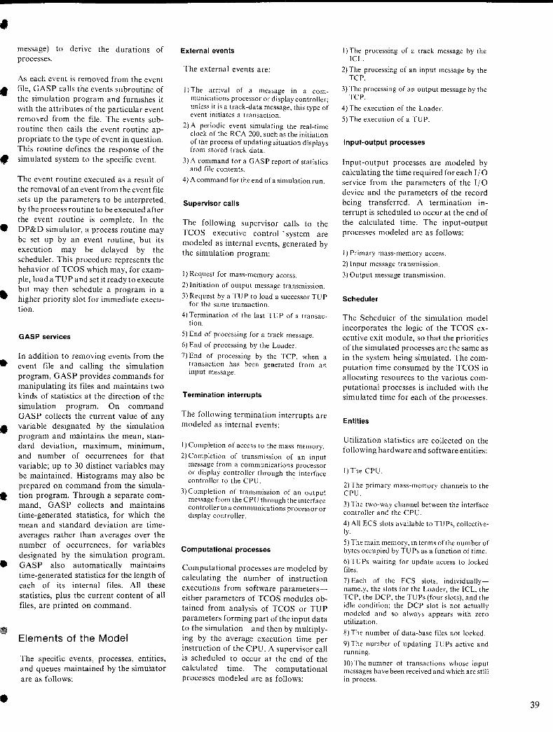
•
•
•
•
•
•
•
•
message) to derive the durations of processes.
As each event is removed from the event file, GASP calls the events subroutine of the simulation program and furnishes it with the attributes of the particular event removed from the file. The events subroutine then calls the event routine appropriate to the type of event in question. This routine defines the response of the simulated system to the specific event.
The event routine executed as a result of the removal of an event from the event file sets up the parameters to be interpreted by the process routine to be executed after the event routine is complete. In the DP&D simulator, a process routine may be set up by an event routine, but its execution may be delayed by the scheduler. This procedure represents the behavior of TCOS which may, for example, load a TU P and set it ready to execute but may then schedule a program in a higher priority slot for immediate execution.
GASP services
In addition to removing events from the event file and calling the simulation program, GASP provides commands for manipulating its files and maintains two kinds of statistics at the direction of the simulation program. On command GASP collects the current value of any variable designated by the simulation program and maintains the mean, standard deviation, maximum, minimum, and number of occurrences for that variable; up to 30 distinct variables may be maintained. Histograms may also be prepared on command from the simulation program. Through a separate command, GASP collects and maintains time-generated statistics, for which the mean and standard deviation are timeaverages rather than averages over the number of occurrences, for variables designated by the simulation program. GASP also automatically maintains time-generated statistics for the length of each of its internal files. All these statistics, plus the current content of all files, are printed on command.
Elements of the Model
The specific events, processes, entities, and queues maintained by the simulator are as follows:
External events
The external events are:
I) The arrival of a message in a communications processor or display controller; unless it is a track-data message, this type of event initiates a transaction.
2) A periodic event simulating the real-time clock of the RCA 200. such as the initiation of the process of updating situation displays from stored track data.
3) A command for a GASP report of statistics and file contents.
4) A command for the end ofa simulation run.
Supervisor calls
The following supervisor calls to the TCOS executive control' system are modeled as internal events, generated by the simulation program:
I) Request for mass-memory access.
2) Initiation of output message transmission.
3) Request by a TU P to load a successor TU P for the same transaction.
4) Termination of the last TUP of a transac-tion.
5) End of processing for a track message.
6) End of processing by the Loader.
7) End of processing by the TCP, when a transaction has been geli.erated from an input message.
Termination interrupts
The following termination interrupts are modeled as internal events:
I) Completion of access to the mass memory.
2) Completion of transmission of an input message from a communications processor or display controller through the interface controller to the CPU. .
3) Completion of transmission of an output message from the CPU through the interface controller to a communications processor or display controller.
Computational processes
Computational processes are modeled by calculating the number of instruction executions from software parameterseither parameters of TCOS modules obtained from analysis of TCOS or TUP parameters forming part of the input data to the simulation-and then by multiplying by the average execution time per instruction of the CPU. A supervisor call is scheduled to occur at the end of the calculated time. The computational processes modeled are as follows:
I) The processing of a track message by the ICL.
2) The processing of an input message by the TCP.
3) The processing of an output message by the TCP.
4) The execution of the Loader.
5) The execution of a TU P.
Input-output processes
Input-output processes are modeled by calculating the time required for each 1/0 service from the parameters of the I I 0 device and the parameters of the record being transferred. A termination interrupt is scheduled to occur at the end of the calculated time. The input-output processes modeled are as follows:
I) Primary mass-memory access.
2) Input message transmission.
3) Output message transmission.
Scheduler
The Scheduler of the simulation model incorporates the logic of the TCOS executive exit module, so that the priorities of the simulated processes are the same as in the system being simulated. The computation time consumed by the TCOS in allocating resources to the various computational processes is included with the simulated time for each of the processes.
Entities
Utilization statistics are collected on the following hardware and software entities:
I)The CPU.
2) The primary mass-memory channels to the CPU.
3) The two-way channel between the interface controller and the CPU.
4) All ECS slots available to TUPs, collectively.
5) The main memory, in terms of the number of bytes occupied by TU Ps as a function of time.
6) TU Ps waiting for update access to locked files.
7) Each of the ECS slots, individuallynamely, the slots for the Loader, the ICL, the TCP, the OCP, the TUPs (four slots), and the idle condition; the OCP slot is not actually modeled and so always appears with zero utilization.
8) The number of data-base files not locked.
9) The number of updating TU Ps active and running.
10) The number of transactions whose input messages ha ve been received and which are still in process.
39
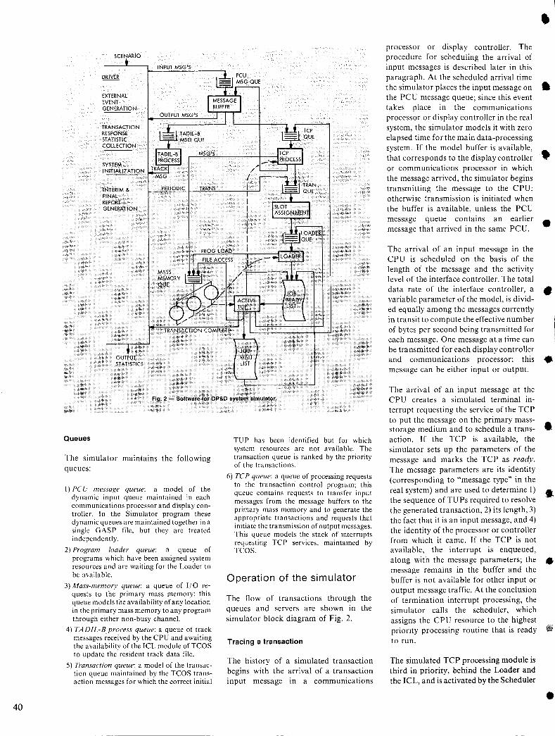
40
SCENARIO
EXTERNAL EVENT GENERATION
TRANSACTION RESPONSE STATISTIC COLLECTION
SYSTEM INITIALIZATION
INTERIM & FINAL REPORT GENERATION
INPUT MSG'S
MSG'S
PERIODIC TRANS
PROG LOAD
FILE ACCESS
OUTPUT STATISTICS
Fig. 2 - Software for DP&D system simulator.
Queues
The simulator maintains the following queues:
I) PC U messaRe queue: a model of the dynamic input queue maintained in each communications processor and display controller. In the Simulator program these dynamic queues are maintained together in a single GASP file, but they are treated independently.
2) ProRram loader queue: a queue of programs which have been assigned system resources and are waiting for the Loader to be available.
3) Mass-memory queue: a queue of I/O requests to the primary mass memory; this queue models the availability of any location in the primary mass memory to any program through either non-busy channel.
4) TADIL-B process queue: a queue of track messages ;eceived by the CPU and awaiting the availability of the ICL module ofTCOS to update the resident track data file.
5) Transaction queue: a model of the transaction queue maintained by the TCOS transaction messages for which the correct initial
TU P has been identified but for which system resources are not available. The transaction queue is ranked by the priority of the transactions.
6) TCP queue: a queue of processing requests to the transaction control program; this queue contains requests to transfer input messages from the message buffers to the primary mass memory and to generate the appropriate transactions and requests that initiate the transmission of output messages. This queue models the stack of interrupts requesting TCP services, maintained by TCOS.
Operation of the simulator
The flow of transactions through the queues and servers are shown in the simulator block diagram of Fig. 2.
Tracing a transaction
The history of a simulated transaction begins with the arrival of a transaction input message in a communications
processor or display controller. The procedure for scheduling the arrival of input messages is described later in this paragraph. At the scheduled arrival time
• the simulator places the input message on • the PCU message queue; since this event takes place in the communications processor or display controller in the real system, the simulator models it with zero elapsed time for the main data-processing system. If the model buffer is available, that corresponds to the display controller • or communications processor in which the message arrived, the simulator begins transmitting the message to the CPU; otherwise transmission is initiated when the buffer is available, unless the PCU message queue contains an earlier message that arrived in the same PCU.
The arrival of an input message in the CPU is scheduled on the basis of the length of the message and the activity level of the interface controller. The total
•
data rate of the interface controller, a • variable parameter of the model, is divid-ed equally among the messages currently in transit to compute the effective number of bytes per second being transmitted for each message. One message at a time can be transmitted for each display controller and communications processor; this • message can be either input or output.
The arrival of an input message at the CPU creates a simulated terminal interrupt requesting the service of the TCP to put the message on the primary massstorage medium and to schedule a trans- • action. If the TCP is available, the simulator sets up the parameters of the message and marks the TCP as ready. The message parameters are its identity (corresponding to "message type" in the real system) and are used to determine I) .. the sequence of TUPs required to resolve the generated transaction, 2) its length, 3) the fact that it is an input message, and 4) the identity of the processor or controller from which it came. If the TCP is not available, the interrupt is enqueued, along with the message parameters; the • message remains in the buffer and the buffer is not available for other input or output message traffic. At the conclusion of termination interrupt processing, the simulator calls the scheduler, which assigns the CPU resource to the highest priority processing routine that is ready to run.
The simulated TCP processing module is third in priority, behind the Loader and the ICL, and is activated by the Scheduler
•
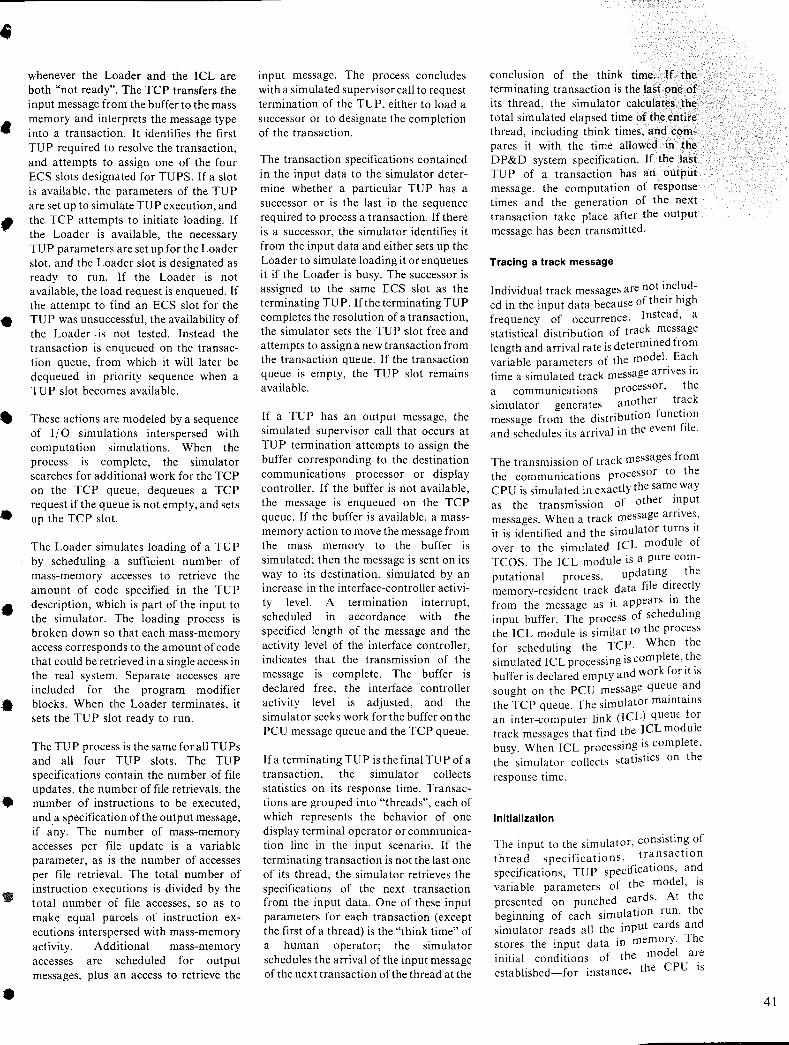
•
•
•
•
•
•
•
whenever the Loader and the ICL are both "not ready". The TCP transfers the input message from the buffer to the mass memory and interprets the message type into a transaction. It identifies the first TUP required to resolve the transaction, and attempts to assign one of the four ECS slots designated for TUPS. If a slot is available, the parameters of the TUP are set up to simulate TU P execution, and the TCP attempts to initiate loading. If the Loader is available, the necessary TUP parameters are set up for the Loader slot, and the Loader slot is designated as ready to run. If the Loader IS not available, the load request is enqueued. If the attempt to find an ECS slot for the TUP was unsuccessful, the availability of the Loader .is not tested. Instead the transaction is enqueued on the transaction queue, from which it will later be dequeued in priority sequence when a TUP slot becomes available.
These actions are modeled by a sequence of 110 simulations interspersed with computation simulations. When the process IS complete, the simulator searches for additional work for the TCP on the TCP queue, dequeues a TCP request if the queue is not empty, and sets up the TCP slot.
The Loader simulates loading of a TUP by scheduling a sufficient number of mass-memory accesses to retrieve the amount of code specified in the TUP description, which is part of the input to the simulator. The loading process is broken down so that each mass-memory access corresponds to the amount of code that could be retrieved in a single access in the real system. Separate accesses are included for the program modifier blocks. When the Loader terminates, it sets the TU P slot ready to run.
The TU P process is the same for all TUPs and all four TUP slots. The TUP specifications contain the number of file updates, the number of file retrievals, the number of instructions to be executed, and a specification of the output message, if any. The number of mass-memory accesses per file update is a variable parameter, as is the number of accesses per file retrieval. The total number of instruction executions is divided by the total number of file accesses, so as to make equal parcels of instruction executions interspersed with mass-memory activity. Additional mass-memory accesses are scheduled for output messages, plus an access to retrieve the
input message. The process concludes with a simulated supervisor call to request termination of the TUP, either to load a successor or to designate the completion of the transaction.
The transaction specifications contained in the input data to the simulator determine whether a particular TUP has a successor or is the last in the sequence required to process a transaction. If there is a successor, the simulator identifies it from the input data and either sets up the Loader to simulate loading it or enqueues it if the Loader is busy. The successor is assigned to the same ECS slot as the terminating TU P. If the terminating TUP completes the resolution of a transaction, the simulator sets the TUP ~lot free and attempts to assign a new transaction from the transaction queue. If the transaction queue is empty, the TUP slot remains available.
If a TUP has an output message, the simulated supervisor call that occurs at TUP termination attempts to assign the buffer corresponding to the destination communications processor or display controller. If the buffer is not available, the message is enqueued on the TCP queue. If the buffer is available, a massmemory action to move the message from the mass memory to the buffer IS simulated; then the message is sent on its way to its destination, simulated by an increase in the interface-controller activity level. A termination interrupt, scheduled m accordance with the specified length of the message and the activity level of the interface controller, indicates that the transmission of the message IS complete. The buffer IS declared free, the interface controller activity level IS adjusted, and the simulator seeks work for the buffer on the PCU message queue and the TCP queue.
Ifa terminating TUP is the final TUP ofa transaction, the simulator collects statistics on its response time. Transactions are grouped into "threads", each of which represents the behavior of one display terminal operator or communication line in the input scenario. If the terminating transaction is not the last one of its thread, the simulator retrieves the specifications of the next transaction from the input data. One of these input parameters for each transaction (except the first of a thread) is the "think time" of a human operator; the simulator schedules the arrival of the input message of the next transaction of the thread at the
conclusion of the think time. If the terminating transaction is the last one of its thread, the simulator calculates the total simulated elapsed time of the entire thread, including think times, and compares it with the time allowed in the DP&D system specification. If the last TUP of a transaction has an output message, the computation of response times and the generation of the next transaction take place after the output message has been transmitted.
Tracing a track message
Individual track messages are not included in the input data because of their high frequency of occurrence. Instead, a statistical distribution of track message length and arrival rate is determined from variable parameters of the model.. Ea~h time a simulated track message arnves m a communications processor, the simulator generates another track message from the distribution functl.on and schedules its arrival in the event file.
The transmission of track messages from the communications processor to the CPU is simulated in exactly the same way as the transmission of other input messages. When a track message arrives, it is identified and the simulator turns It over to the simulated ICL module of TCOS. The ICL module is a pure computational process, updating. the memory-resident track data fde directly from the message as it appears in ~he input buffer. The process of scheduhng the ICL module is similar to the process for scheduling the TCP. When the simulated ICL processing is complete, the buffer is declared empty and work for It IS sought on the PCU message que~e and the TCP queue. The simulator mamtams an inter-computer link (ICL) quem. for track messages that find the ICL module busy. When ICL processing is complete, the simulator collects statistics on the
response time.
Initialization
The input to the simulator, consisting of thread specifications, tra.nsactlOn specifications, TU P specificatIOns, and variable parameters of the model, IS presented on punched cards. At the beginning of each simulation run, the simulator reads all the input cards and stores the input data in memory. The initial conditions of the model are established-for instance, the CPU is
41
42
__________________________ ~~~~~~~~Y~~~l~ ______________ __ _
SIMlJLATIO" PROJECT ~0.1001 8Y TAYLOR
___ ~_~ __ ~ ________ ___ l>~T!..lQ!_U '-l9~~ _______ ~~~~~~ __ ~ _________ _
_________ --. ____________ !!I.;'!.Q~~_!1~O_!~OQO_U.!!.E_~lJ2~* _____________ _
# EVENTS I TRACE # (PARAli. liD. 1) • 72.0000 0.0000 1.0000 o.nooo NO OF TUP DESCRIPTOR (PARAM. "'0. 2) 94.0000 1.0000 0.0000 0.0000 NO OF TRANSACTIONS (PARAM. 1'0. 3) 202.0000 0.0000 90.0000 91.0000
---TADYLARRTVALRATE--(PARAM.-NO~-4)---T:ooO'O---O;-O'OlO--200-;OoO0----1_;0000--
TAOIL MSG LENI PCU '# (PARAM. "0. 5) 20.0000 7.0000 0.0000 0.0000 -- -DRUM RATElLffENCY-- - (PARAM;- NO-: --&) 312000 ~O'OOo - - - -0-;6080- - - -0: 0000--- 0.0600--
# OF PCU'S (PARAM. "'D. 7) 7.0000 0.0000 0.0000 0.0000 INTERFACE DATA RATE (PARAM. «D. 8) 150000.0000 o.ooeo 0.0000 0.0000 CPU SPEEO- USECIINST (PARAM. NO.9) 4.0000 0.0000 0.0000 0.0000
---~DATEMOoE------(~RAM;-~-;-1O)---Z:ODOo---O-;0000---4~OoOO---o.oOoa--
UPDATE THRESHOLDS (PARAM. NO. 11) 50.0000 55.0000 2.0000 0.0000 -HISTO- #lPARAM----(PARAM;- NO-: -121---1_;_0060--- T;-Oooo- - --0:0000---0;0600--
HISTO #2 PARAM (PARAM. NO. 13) 2.0000 2.0000 0.0000 0.0000 HISTO #3 PARAH (PARAM. NO. 14) 5.0000 5.0000 0.0000 0.0000
___ J'JU<:!.R-'-D'~.QQE _____ .1~~~,,-.!'.o-,_.1~ ____ 0-,-0.QQ.O ____ O-,-Q92-'L ___ 02Q!l~ ___ ~ • .QQ!lQ. __
-----------------------------~~N~AffaOAT~*-----------------
CODE MEAN STD.DEV. MIN. MAX. 08S.
TAOIL-B RESPONSE THE 1 0'.0068 0.0133 0.0045 0.3216 1158 ---TRANs-RESP;-'TTMETAfL:-----2---Z-:8330---f.8D9S--0-:2B96---27.7982--197------
OP RESPONSE TIME 1 3 0.9023 0.8293 0.3226 5.0194 34 ---OP-RE5PDNSETiME2-------4---2~703---1:926S--0-;-4850---B.6Bl5---83------
OP RESPONSE TIME 3 5 '5.6879 7.2342 2.4242 27.7982 12 UPDATE LT THRESHOLD 6 0.1161 0.4190 0.0000" 3.0000 112 UPDATE GT THRESHOLD 7 0.2857 0.6694 0.0000 4.0000 133
7--pfRfoOIC-#T---~------8---0_;_1303---0.1524---0-;06-[l.--0~016--i400------
PERIODIC # 2 9 0.5538 0.0365 0.5004 - 0.8267 399 -- -IiFfLES-~OATEDTTUP ----lo----2-;7"9fB-- -1.4206-- -1-;0000---9 ;0000 - -245------
PROSOK UPOATE-2 11 1.0000 0.0000 1.0000 1.0000 3 CHECK ON ORAND 12 0.4995 0.2855 0.0009 0.9979 298
-----------------------------"*riMEGENERATEODATA*.--------------
___________________ <;QilE ___ "!.~ ____ S~"-'Q.E.'!.. ___ J1!N-'- ____ f:l.A~'__IDJ~LTJ'!.E __ _
CPU lIT!L!ZATION 0.2194 0.4138 0.0000 1.0000 300.0000 CHANNEL UTILIZATION 0.1755 0.3881 0.000.0 2.0000 300.0000 INTERFACE ACTIVITY 3 0.0895 _Q..lO'~Q. ___ o.QO~0 ___ 2c9Q.o.Q __ 3.QD.!Q.0.2~ __ _
--USERSLOTS-UTfi.iiEo------,,--O:Ol4Z-- 0.1182 0,0000 1.0000 300.0000 -- MEMORY UTILIZATION 5 B66.3860 8728.1108 0.0000 99000.0000 300.0000
-- - uPDATES- wAITEo--------6"- - 0 ;-0060 - - - 0.'0600- --0-;0000---0 ;0000--300;0000----LOADER UTILIZATION 7 0.0004 0.0197 0.0000 1.0000 300.0000 ICL SLOT UTILIZATION 8 0.0989 0.2985 0.0000 1.0000 300.0000 Tep SLoT UTILIZATION 9 0.i148 0.3188 0.0000 1.0000 300.0000
- --oepsLor-uTIliZATIOIC- - -10--0;-0000- - - 0;0500 ---0-;0000-- -0;0000 --300.0000-- --TUP #1 UTILIZATION 11 0.0053 0.0729 0.0000 1.0000 300.0000
---"fuP#2ufiLIZATION-----lz--o;-0000---0.00oo---0-;oooo--o:oo00-300;0000---TUP #3 UTILIZATION 13 0.0000 0.0000 0.0000 0.0000 300.0000 TUP #4 UTILIZATION 14 0.0000 0.0000 0.0000 0.0000 300.0000
___ 1.0J,L'O_Hli __________ J,~ __ _"_'_7J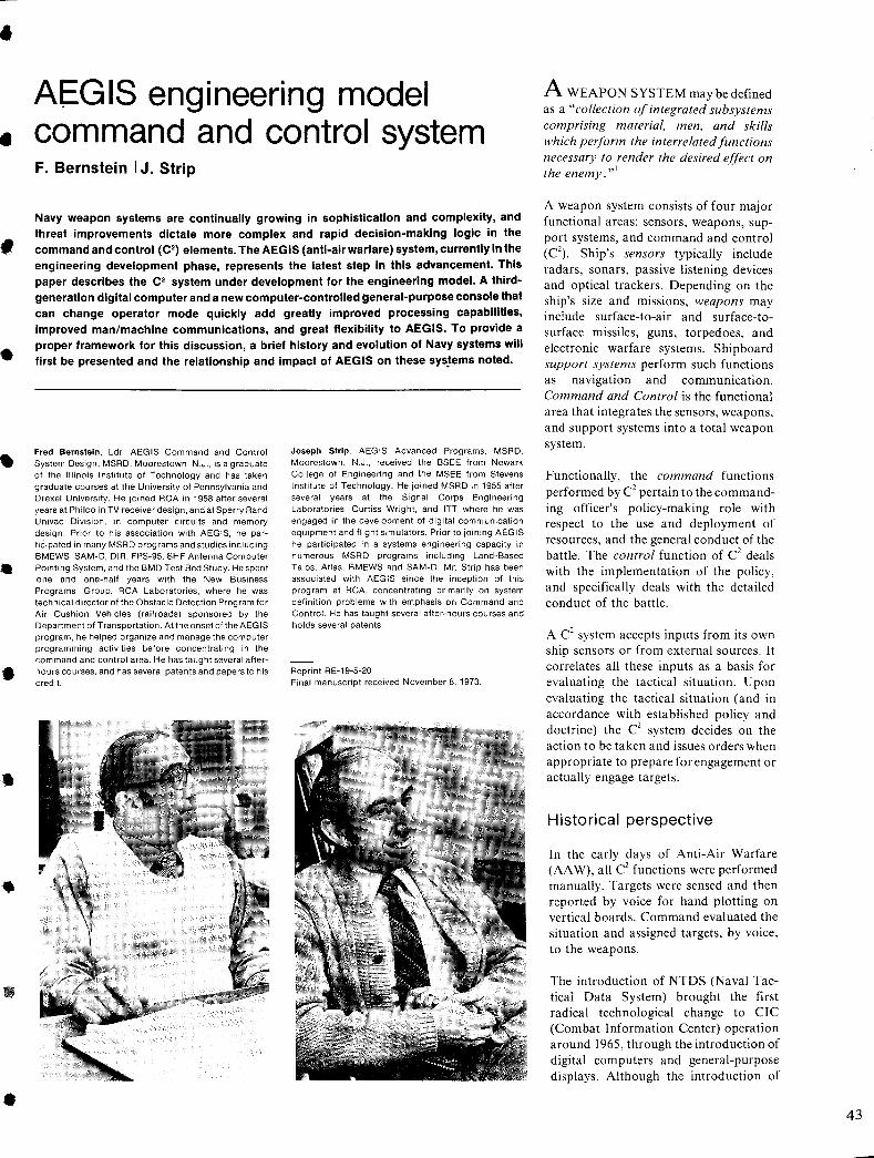
•
•
,
•
•
..
•
•
•
AEGIS engineering model command and control system F. Bernstein I J. Strip
Navy weapon systems are continually growing in sophistication and complexity, and threat improvements dictate more complex and rapid decision-making logic in the command and control (C2) elements. The AEGIS (anti-air warfare) system, currently in the engineering development phase, represents the latest step in this advancement. This paper describes the C2 system under development for the engineering model. A thirdgeneration digital computer and a new computer-controlled general-purpose console that can change operator mode quickly add greatly improved processing capabilities, improved man/machine communications, and great flexibility to AEGIS. To provide a proper framework for this discussion, a brief history and evolution of Navy systems will first be presented and the relationship and impact of AEGIS on these sys~ems noted.
Fred Bernstein, Ldr. AEGIS Command and Control System Design, MSRD, Moorestown, N.J., is a graduate of the Illinois Institute of Technology and has taken graduate courses at the University of Pennsylvania and Drexel University. He joined RCA in 1958 after several years at Philco in TV receiver design, and at Sperry Rand Univac Division, in computer circuits and memory design. Prior to his association with AEGIS, he participated in many MSRD programs and studies including BMEWS, SAM-D, DIR, FPS-95, SHF Antenna Computer Pointing System, and the BMD Test Bed Study. He spent one and one-half years with the New Business Programs Group, RCA Laboratories, where he was technical director of the Obstacle Detection Program for Air Cushion Vehicles (railroads) sponsored by the Department of Transportation. At the onset olthe AEGIS program, he helped organize and manage the computer programming activities before concentrating in the command and control area. He has taught several afterhours courses, and has several patents and papers to his credit.
Joseph Strip, AEGIS Advanced Programs, MSRD, Moorestown, N.J., received the BSEE from Newark College of Engineering and the MSEE from Stevens Institute of Technology. He joined MSRD in 1955 after several years at the Signal Corps Engineering Laboratories, Curtiss Wright, and ITT where he was engaged in the development of digital communication equipment and flight simulators. Prior to joining AEGIS he participated in a systems engineering capacity in numerous MSRD programs including Land-Based Talos, Atlas, BMEWS and SAM-D. Mr. Strip has been associated with AEGIS since the inception of this program at RCA, concentrating primarily on system definition problems with emphasis on Command and Control. He has taught several after-hours courses and holds several patents.
Reprint RE-19-5-20 Final manuscript received November 8,1973.
A WEAPON SYSTEM may be defined as a "collection of integrated subsystems comprising material, men, and skills which perform the interrelated functions necessary to render the desired effect on the enemy. ,,1
A weapon system consists of four major functional areas: sensors, weapons, support systems, and command and control (C\ Ship's sensors typically include radars, sonars, passive listening devices and optical trackers. Depending on the ship's size and missions, weapons may include surface-to-air and surface-tosurface missiles, guns, torpedoes, and electronic warfare systems. Shipboard support systems perform such functions as navigation and communication. Command and Control is the functional area that integrates the sensors, weapons, and support systems into a total weapon system.
Functionally, the command functions performed by C2 pertain to the commanding officer's policy-making role with respect to the use and deployment of resources, and the general conduct of the battle, The control function of C2 deals with the implementation of the policy, and specifically deals with the detailed conduct of the battle.
A C2 system accepts inputs from its own ship sensors or from external sources. It correlates all these inputs as a basis for evaluating the tactical situation, Upon evaluating the tactical situation (and in accordance with established policy and doctrine) the C2 system decides on the action to be taken and issues orders when appropriate to prepare for engagement or actually engage targets.
Historical perspective
In the early days of Anti-Air Warfare (AA W), all C2 functions were performed manually. Targets were sensed and then reported by voice for hand plotting on vertical boards. Command evaluated the situation and assigned targets, by voice, to the weapons.
The introduction of NTDS (Naval Tactical Data System) brought the first radical technological change to CIC (Combat Information Center) operation around 1965, through the introduction of digital computers and general-purpose displays. Although the introduction of
43
44
NTDS modified the technology used in CIe's, it did not materially alter the nature of CIC operation. The sensors still provided video for the operator to use for manual-track data-point entry (although general-purpose computers were used to smooth this data, display the tactical situation, and perform computations to assist C2 personnel in their decisionmaking). Target assignments continued to be made by operators (except for special cases), but via consoles rather than voice.
AEGIS impact on C2
AEG IS represents the latest development in the evolution of AA W combat systems. The AN/SPY-I introduces a fully automatic radar to perform search and tracking, and the use of a midcoursecommanded missile increases the firepower of the ship. The introduction of these innovations into the fleet with the attendant high target-handling capability brings a requirement for considerable expansion of automation in C2 and requires that command be exercised by negation.
Originally, AEGIS was designed for installation in a JO,OOO-ton DLGN-38 class ship. The discussion that follows briefly describes this ship's combat system and the role of C2 within it.
DLGN 38 combat system
The combat system of the DLGN-38 ship is shown in simplified form in Fig. I. The AEG IS part of the system consists of Radar Set, AN/SPY-I; Weapon Direction System (WDS), Mk 12; Fire Control System, Mk 99 (consisting of a Tracking Illuminator, Mk 91 and Slaved Illuminator, Mk 90) the Guided Missile Launchers, Mk 26; the midcoursecommand-version of the standard missile, SM-2; and finally the AEGIS portion of the C2 system, Mk 130.
In addition to AA W, this ship also performs surface warfare and antisubmarine warfare missions. These missions, as well as AEGIS, are supported by the additional sensors shown in the Fig. I, and by the gun and underwater-battery fire-control systems; the latter shares one of the launchers with AEGIS. The C2
system integrates the AEG IS and nonAEGIS elements into a total combat
system, and interfaces these elements with command personnel in CIe.
Functionally, the AEGIS system contains three control segments: AN/SPY-I control, the weapon direction system, and command and control (C2
). The functions performed by these three segments are shown in Fig. 2. The AN/SPY-I control segment controls the operation of the phased-array radar in target surveillance and target and missile tracking. It also controls uplink and downlink communications with the SM-2 missile (RIM 66-C).
The baseline design of the C2 segment in the AEGIS combat ship was based on the use of standa-rd digital computers (AN / UYK-7) and associated peripherals, and an updated general purpose display system, Display Group AN / UY A-4. Auxiliary equipment in the C2 system includes switching equipment, a digital clock, a magnetic disk and a multiplexer to allow non-C2 computers to access the disk.
Operational overview of AEGIS
The operation of the AEGIS weapon system is shown in Fig. 3. 2 It begins with a search-and-detect operation by the phased-array radar. A detected target is placed into track by the radar and passed to the command-and-control system for evaluation. Once a target is determined to be a threat by the command-and-control system, orders are furnished to the weapon-direction system to develop a fire-control solution. Missiles are loaded on the launcher by commands furnished by the weapon-di-rection system. The phased-array radar furnishes target track data to the fire-control system which designates the launcher firing position through the weap,on-direction system.
After launch, the missile is guided by the phased-array radar until the homing phase of the flight at which time the firecontrol system illuminator is slaved to target coordinates supplied by the radar, thereby furnishing the illumination on which the missile can home. Following intercept, the illuminator is available for the next threat. In the meantime, the multifunction phased-array radar, coupled with the multicomputer control system, continuously searches for new targets and simultaneously tracks targets already detected or engaged. The result is virtually instantaneous response to any
new single or multiple threat that appears. These features add up to a firepower capability adequate to meet the threats of 1975 and beyond.
AEGIS EDM-1 •
Under the terms of the AEGIS contract, RCA is responsible for developing the AN/SPY-I control and the WDS-Mk 12 • computer programs. However, in the case of C2
, RCA's task was "to develop sufficient C2 segment capability to permit satisfactory performance demonstration" of the other segments in the engineering models, and to provide liaison with the combat system contractor.
For convenience of discussion, functions allocated to C2 can be subdivided into two categories: "AEGIS functions" consist of the set of functions that must be implemented to allow AEGIS to perform
•
its primary mission of conducting missile • engagements; "non-AEGIS functions" performed by C2 are associated with nonAEGIS weapon systems or in coopera-tion with other ships.
The design approach adopted for the first engineering development model (EDM- '. I) was to establish a basic architecture for the implementation of the" AEGIS functions" of C2 that would generally conform to the expected design and processing flow of the final combat system, and implementing these functions only to the • degree required to satisfy EDM-I test objectives. The major requirements allocated to EDM-I C2 are:
I) Establish operating configuration, doctrine, and modes.
2) Establish and maintain system track files. •
3) Identify targets.
4) Perform threat evaluation.
S) Assign weapons.
6) Control engagements.
7) Display information.
8) Support EDM-I testing.
Major EDM-1 functions
The major EDM-I functions designed to satisfy these requirements are outlined in the following paragraphs:
Initialization-prepares a completely dormant system for operational use, allowing the operational computer program to be loaded from tape or disk or both with minimal operator effort.
•
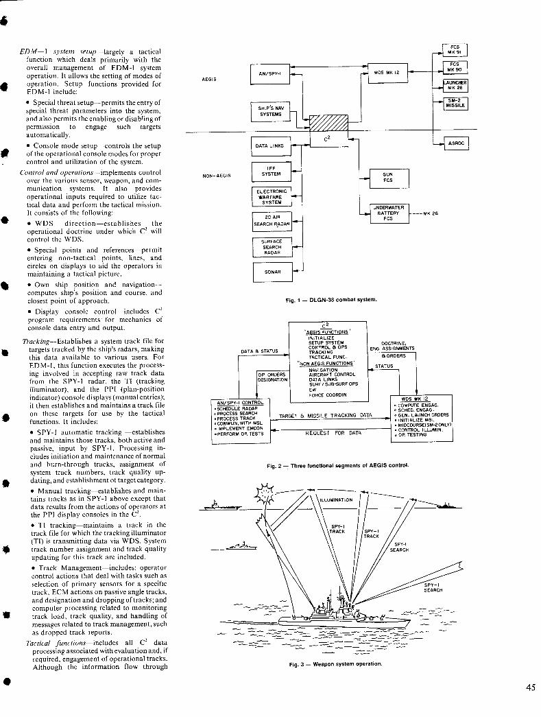
•
•
•
•
•
•
•
•
EDM-I system setup-largely a tactical function which deals primarily with the overall management of EDM-I system operation. It allows the setting of modes of operation. Setup functions provided for EDM-I include:
• Special threat setup-permits the entry of special threat parameters into the system, and also permits the enabling or disabling of permiSSIOn to engage such targets automatically.
• Console mode setup-controls the setup of the operational console modes for proper control and utilization of the system.
Control and operations-implements control over the various sensor, weapon, and communication systems. It also provides operational inputs required to utilize tactical data and perform the tactical mission. It consists of the following:
• WDS direction-establishes the operational doctrine under which C' will control the WDS.
• Special points and references-permit entering non-tactical points, lines, and circles on displays to aid the operators in maintaining a tactical picture.
• Own ship position and navigationcomputes ship's position and course, and closest point of approach.
• Display console control-includes C' program requirements for mechanics of console data entry and output.
Track ing-Establishes a system track file for targets tracked by the ship's radars, making this data available to various users. For EDM-I, this function executes the processing involved in accepting raw track data from the SPY-I radar, the TI (tracking illuminator), and the PPI (plan-position indicator) console displays (manual entries); it then establishes and maintains a track file on these targets for use by the tactical functions. It includes:
• SPY-I automatic tracking -establishes and maintains those tracks, both active and passive, input by SPY-I. Processing includes initiation and maintenance of normal and burn-through tracks, assignment of system track numbers, track quality updating, and establishment of target category.
• Manual tracking-establishes and maintains tracks as in SPY-I above except that data results from the actions of operators at the PPI display consoles in the C'.
• TI tracking-maintains a track in the track file for which the tracking illuminator (TI) is transmitting data via WDS. System track number assignment and track quality updating for this track are included.
• Track Management-includes: operator control actions that deal with tasks such as selection of primary sensors for a specific track, ECM actions on passive angle tracks, and designation and dropping of tracks; and computer processing related to monitoring track load, track quality, and handling of messages related to track management, such as dropped track reports.
Tactical functions-includes all C2 data processing associated with evaluation and, if required, engagement of operational tracks. Although the information flow through
AEGIS
NON-AEGIS
---MK 26
Fig. 1 - DLGN-38 combat system.
C2
"A~GI~TuNcTIQNS" INITIALIZE SETUP SYSTEM DOCTRINE, CO~'TROL a OPS ENG. ASSIGNMENTS
DATA a STATUS TRACKING TACTICAL FUNC. aORDERS
"NON AEGIS FUNCTIONS' STATUS
NAVIGATION
\
OP ORDERS AIRCRAFT CONTROL DESIGNATION DATA LINKS
SURF I SUB-SURF OPS EW FORCE COORDIN.
WDS MK 12 ANI SPY-I CONTROL
• COMPUTE ENGAG. o SCHEDULE RADAR o SCHEO. EN GAG . • PROCESS SEARCH TARGET a MISSILE TRACKING DATA • GEN. LAUNCH ORDERS • PROCESS TRACK o INITIALIZE MSL oCOMMUN.WITH MSL • MIDCOURSE(SM-20NLYl • IMPLEMENT EMCON o CONTROL I LLUM IN. • PERFORM OP. TESTS REQUEST FOR DATA o OP. TESTING
Fig. 2 -: Three functional segments of AEGIS control.
---=-- ~ - - -:; - -=:-~ -~~~==-~---
Fig. 3 - Weapon system operation.
45
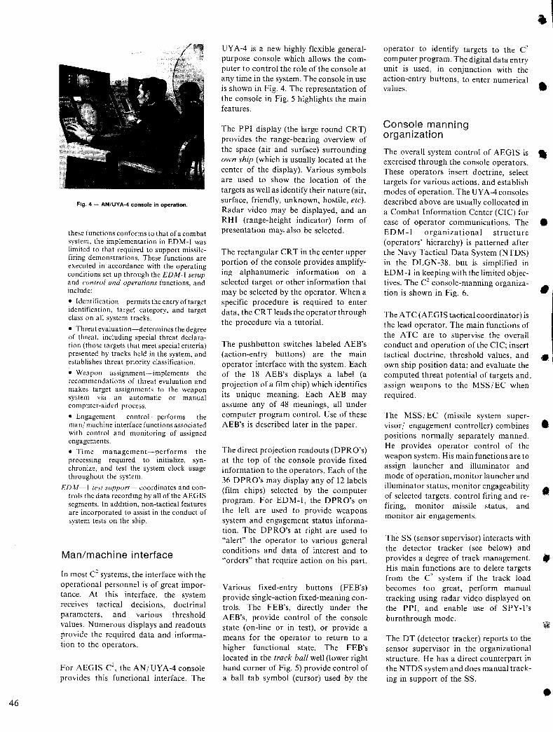
46
Fig. 4 - AN/UY A-4 console in operation.
these functions conforms to that of a combat system, the implementation in EDM-I was limited to that required to support missilefiring demonstrations. These functions are executed in accordance with the operating conditions set up through the EDM-I setup and control and operations functions, and include:
• Identification-permits the entry of target identification, target category, and target class on all system tracks.
• Threat evaluation-determines the degree of threat, including special threat declaration (those targets that meet special criteria) presented by tracks held in the system, and establishes threat priority classification.
• Weapon assignment-implements the recommendations of threat evaluation and makes target assignments to the weapon system via an automatic or manual computer-aided process.
• Engagement control-performs the man/ machine interface functions associated with control and monitoring of assigned engagements.
• Time management-performs the processing required to initialize, synchronize, and test the system clock usage throughout the system.
EDM-I test support·~ coordinates and controls the data recording by all of the AEGIS segments. In addition, non-tactical features are incorporated to assist in the conduct of system tests on the ship.
Man/machine interface
In most C2 systems, the interface with the operational personnel is of great importance. At this interface, the system receives tactical decisions, doctrinal parameters, and various threshold values. Numerous displays and readouts provide the required data and information to the operators.
For AEGIS C2, the AN/UYA-4console
provides this functional interface. The
UY A-4 is a new highly flexible generalpurpose console which allows the computer to control the role of the console at any time in the system. The console in use is shown in Fig. 4. The representation of the console in Fig. 5 highlights the main features.
The PPI display (the large round CRT) provides the range-bearing overview of the space (air and surface) surrounding own ship (which is usually located at the center of the display). Various symbols are used to show the location of the targets as well as identify their nature (air, surface, friendly, unknown, hostile, etc). Radar video may be displayed, and an RH I (range-height indicator) form of presentation may. also be selected.
The rectangular CRT in the center upper portion of the console provides amplifying alphanumeric information on a selected target or other information that may be selected by the operator. When a specific procedure is required to enter data, the CR T leads the operator through the procedure via a tutoriaL
The pushbutton switches labeled AEB's (action-entry buttons) are the main operator interface with the system. Each of the 18 AEB's displays a label (a projection of a film chip) which identifies its unique meaning. Each AEB may assume any of 48 meanings, all under computer program controL Use of these AEB's is described later in the paper.
The direct projection readouts (DPRO's) at the top of the console provide fixed information to the operators. Each of the 36 DPRO's may display any of 12 labels (film chips) selected by the computer program. For EDM-I, the DPRO's on the left are used to provide weapons system and engagement status information. The DPRO's at right are used to "alert" the operator to various general conditions and data of interest and to "orders" that require action on his part.
Various fixed-entry buttons (FEB's) provide single-action fixed-meaning controls. The FEB's, directly under the AEB's, provide control of the console state (on-line or in test), or provide a means for the operator to return to a higher functional state. The FEB's located in the track ball well (lower right hand corner of Fig. 5) provide control of a ball tab symbol (cursor) used by the
operator to identify targets to the C2
computer program. The digital data entry unit is used, in conjunction with the action-entry buttons, to enter numerical values.
Console manning organization
The overall system control of AEGIS is exercised through the console operators. These operators insert doctrine, select targets for various actions, and establish modes of operation. The UY A-4 consoles described above are usually collocated in a Combat Information Center (CIC) for ease of operator communications. The EDM-J organizational structure (operators' hierarchy) is patterned after the Navy Tactical Data System (NTDS) in the DLGN-38, but is simplified in ED M -I in keeping with the limited objectives. The C2 console-manning organization is shown in Fig. 6.
The A TC (AEGIS tactical coordinator) is the lead operator. The main functions of the A TC are to supervise the overall conduct and operation of the CIC; insert tactical doctrine, threshold values, and own ship position data; and evaluate the computed threat potential of targets and. assign weapons to the MSS/EC when required.
The MSSj EC (missile system supervisor/ engagement controller) combines positions normally separately manned. He provides operator control of the weapon system. His main functions are to assign launcher and illuminator and mode of operation, monitor launcher and illuminator status, monitor engageability of selected targets, control firing and refiring, monitor missile status, and monitor air engagements.
The SS (sensor supervisor) interacts with the detector tracker (see below) and provides a degree of track management. His main functions are to delete targets from the C2 system if the track load becomes too great, perform manual tracking using radar video displayed on the PPI, and enable use of SPY-I's burn through mode.
The DT (detector tracker) reports to the sensor supervisor in the organizational structure. He has a direct counterpart in the NTDS system and does manual tracking in support of the SS.
•
•
•
•
•
•
•
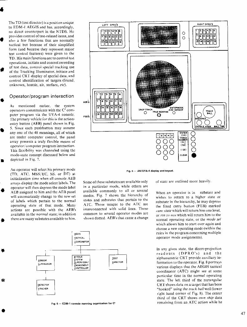
•
•
•
•
•
•
•
•
The TO (test director) is a position unique to EOM-I AEGIS and has, accordingly, no direct counterpart in the NTOS. He provides control of test-related items, and also a few functions that are normally tactical but because of their simplified form (and because they represent major test control features) were given to the TO. His main functions are to control test operations, initiate and control recording of test data, control special tracking use of the Tracking Illuminator, initiate and control CRT display of special data, and control identification of targets (friend, unknown, hostile, air, surface, etc).
Operator/program interaction ,
AEB 5
LEFT DPRO'S
o o
ENTERMOOE
RIGHT DPRO'S
As mentioned earlier, the system operators communicate with the C2 computer program via the UY A-4 console. The primary vehicle for this is the actionentry button (AEB) panel shown in Fig. 5. Since each pushbutton may assume anyone of the 48 meanings, all of which are under computer control, the panel array presents a truly flexible means of operator I computer program interaction. This flexibility was channeled using the mode-state concept discussed below and depicted in Fig. 7.
DROP TRACK A NO SENSOR o TRUE BEARING 0 o o FEB'S
ENTER
1I1 9 1 sHoI (54) TRACK
000 NUMBER (51 )
000 ( 52)
000 ( 53)
0 CLEAR
SEQUENCE
00 ENABLE HOOK
o o o o •
o BALL TAS
An operator will select his primary mode (TO, ATC, MSS/EC, SS, or OT) at initialization time when all console AEB arrays display the mode select labels. The operator will then depress the mode label AEB assigned to him and the AEB panel will automatically change to the new set of labels which pertain to the normal operating state of that mode. Many actions are possible with the AEB's available in the normal state; in addition there are many substates available to him.
Fig. 5 - AN/UY A-4 display and keyset.
I ~EN50R
2UPERVISOR
\
QETECTOR
TRACKER
~EGI5
Some of these substates are available only in a particular mode, while others are available commonly to all or several modes. Fig. 7 shows the hierarchy of states and substates that pertain to the A TC. Those unique to the A TC are interconnected with solid lines. Those common to several operator ,modes are shown dotted. AEB's that cause a change
IACTICAL
fOOROINATOR
I I l
MISSILE rEST
SYSTEM ~UPERVI50R I QIRECTOR
iNGAGEMENT .fONTROLLER
Fig. 6 - EDM~1 console manning organization for C2
of state are outlined more heavily.
When an operator is in substate and wishes to return to a higher state or substate in the hierarchy, he may depress the fixed entry button (FEB) marked cane state which will return him one level, or rtn to nos which will return him to the normal operating state, or the mode set which allows him to start over again and choose a new operating mode (within the rules in the program concerning multiple operator mode assignments).
In any given state, the direct-projection readouts (OPRO's) and the alphanumeric CRT provide auxiliary information to the operator. Fig. 8 portrays various displays that the AEGIS tactical coordinator (ATC) might see at some particular time in the normal operating state. The left third of the rectangular CR T shows data on a target that has been "hooked" using the track ball well (lower right hand corner of Fig. 8). The center third of the CRT shows own ship data remaining from an A TC action while he
47
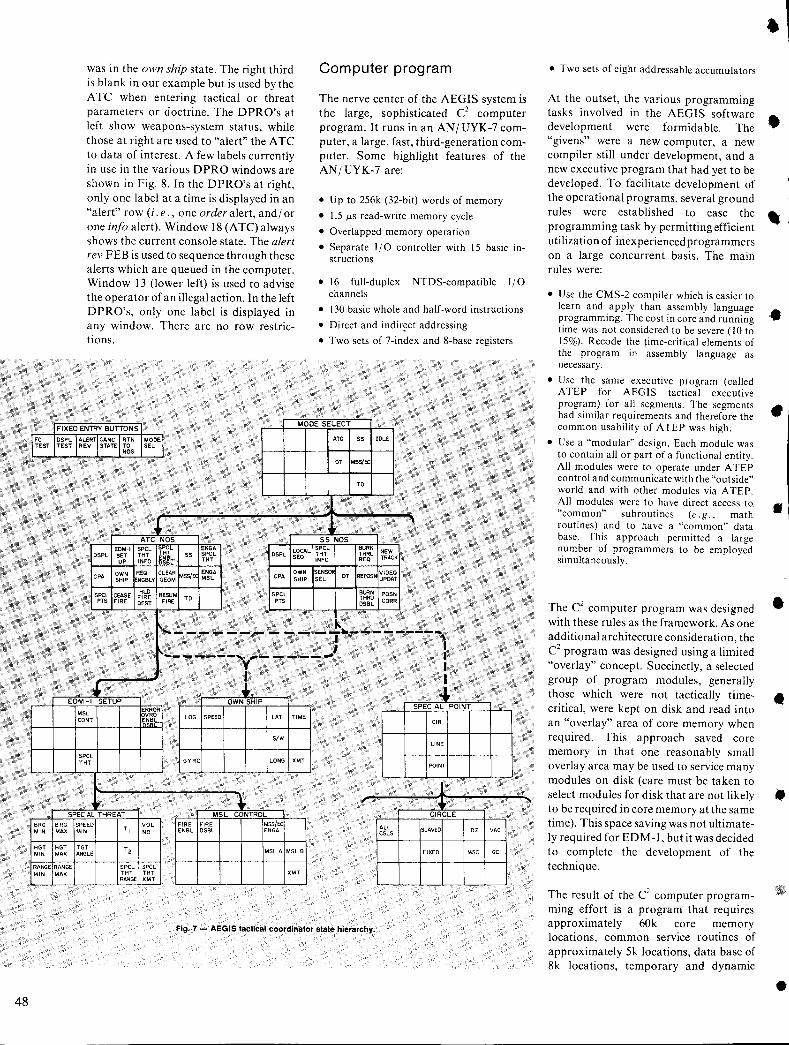
FC TEST
BRG MIN
HGT MIN
RANGE MIN
48
was in the own ship state. The right third is blank in our example but is used by the A TC when entering tactical or threat parameters or doctrine. The DPRO's at left show weapons-system status, while those at right are used to "alert" the A TC to data of interest. A few labels currently in use in the various DPRO windows are shown in Fig. 8. In the DPRO's at right, only one label at a time is displayed in an "alert" row (i. e., one order alert, and/ or one info alert). Window 18 (ATC) always shows the current console state. The alert rev FEB is used to sequence through these alerts which are queued in the computer. Window 13 (lower left) is used to advise the operator of an illegal action. In the left DPRO's, only one label is displayed in any window. There are no row restrictions.
Computer program
The nerve center of the AEGIS system is the large, sophisticated C2 computer program. It runs in an AN/UYK-7 computer, a large, fast, third-generation computer. Some highlight features of the AN/UYK-7 are:
• Up to 256k (32-bit) words of memory
• 1.5 p.s read-write memory cycle
• Overlapped memory operation
• Separate I/O controller with 15 basic instructions
• 16 full-duplex NTDS-compatible I/O channels
• 130 basic whole and half-word instructions
• Direct and indir~ct addressing
• Two sets of 7-index and 8-base registers
I FIXED ENTRY BUTTONS MODE SELECT
DSPL ALERT CANe RTN MODE ATC SS IDLE TEST REV STATE TO SEL
NOS
OT MSS/EC
TO
~ ~
, ATC NOS SS NOS
EDM-I SPCL SPCL ENGA LOCAL SPCl BURN NEW
DSPL SET THT ~~i~~ SS SPCL OSPL SEO THT THRU
TRACK UP INFO THT INFO REO
OWN REO CLEAR Jt..SS/EC
ENGA CPA
OWN SENSO OT REPOSN
VIDEO CPA
SHIP ENGBLY GEOM MSL SHIP SEL UPDAT
SPCL CEASE HLO RESUM SPCL BURN POSN FIRE TO THRU PTS FIRE DEST FIRE PTS Dsel CORR
.. [' ..... _________ - _____ lIr. ______
I
,,-------, ,------, V
• ! EOM I SETUP OWN SHIP
~fROR MSL VRO LOG SPEED LAT TIME CONT 1f,~~1-
SPECIAL POINT
CIR
s/w LINE
SPCL THT GYRO LONG XMT
POINT
• ~ , SPECIAL THREAT MSL CONTROL
BRG SPEED VOL FIRE FIRE MSS/EC ALL
MAX MIN T, NO ENBL aSBL ENGA CSLS SLAVED az VAC
HGT TGT T2 MSL A MSl B MAX ANGLE FIXED MSC GC
RANGE SPCL 3PCL MAX THT THT XMT
RANGE XMT
Fig. 7 - AEGIS tactical coordinator state hierarchy.
• Two sets of eight addressable accumulators
At the outset, the various programming tasks involved in the AEGIS software development were formidable. The "givens" were a new computer, a new compiler still under development, and a new executive program that had yet to be developed. To facilitate development of the operational programs, several ground rules were established to ease the programming task by permitting efficient utilization of inexperienced programmers on a large concurrent basis. The main rules were:
• Use the CMS-2 compiler which is easier to learn and apply than assembly language programming. The cost in core and running time was not considered to be severe (\ 0 to 15%). Recode the time-critical elements of the program in assembly language as necessary.
• Use the same executive program (called A TEP for AEG IS tactical executive program) for all segments. The segments had similar reg uirements and therefore the common usability of A TEP was high.
• Use a "modular" design. Each module was to contain all or part of a functional entity. All modules were to operate under ATEP control and communicate with the "outside" world and with other modules via A TEP. All modules were to have direct access to "common" subroutines (e. g., math routines) and to have a "common" data base. This approach permitted a large number of programmers to be employed simultaneously.
The C2 computer program was designed with these rules as the framework. As one additional architecture consideration, the C2 program was designed using a limited "overlay" concept. Succinctly, a selected group of program modules, generally those which were not tactically timecritical, were kept on disk and read into an "overlay" area of core memory when required. This approach saved core memory in that one reasonably small overlay area may be used to service many modules on disk (care must be taken to select modules for disk that are not likely to be required in core memory at the same time). This space saving was not ultimately required for EDM-I, but it was decided to complete the development of the technique.
The result of the C2 computer programming effort is a program that requires approximately 60k core memory locations, common service routines of approximately 5k locations, data base of 8k locations, temporary and dynamic
•
•
•
•
•
•
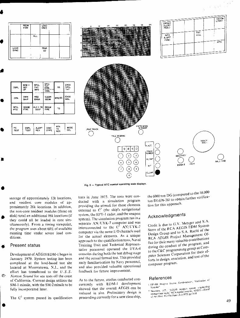
•
•
•
•
•
•
•
•
RECM LOAD FIRE ONCE
KILL
LCHR TRKR SYNC GO
EDM-I SPCL SPCL ENGA THT
DSPL SET THT ~NJI~ __ 55 5PCL UP INFO THT
D5BL
CPA OWN REQ CLEAR ENGA SHIP ENGA GEOM
M55/EC M5L
SPCL CEASE HLO FIRE RESUM PTS FIRE DEST FIRE TO
storage of approximately 12k locations, and resident core modules of approximately 26k locations. In addition, the non-core resident modules (those on disk) total an additional 16k locations (if they could all be loaded in core simultaneously). From a timing viewpoint, the program uses about 60% of available running time under severe load conditions.
Present status
Development of AEGIS EDM-I began in January 1970. System testing has been completed at the land-based test site located at Moorestown, N.J., and the effort has transferred to the U. S. S. Norton Sound for sea tests off the coast of California. Current design utilizes the SM-l missile, with the SM-2 missile to be fully incorporated later.
The C2 system passed its qualification
TRUE BEARING o J,J9JsHoJ 808 888 888
G
FUNCT. 0 TRACK 0
NUMBER
HEIGHT 0 SIF 0
CLEAR.
ORDER ALERT PEND
TGT
INFO KILL ALERT PEND
Fig. 8 _ Typical ATe normal operating state displays.
tests in June 1973. The tests were conducted with a simulation program providing the stimuli for those elements external to C2 (the ship's navigational system, the Spy -I radar, and the weapon system). The simulation program ran in a separate AN I UYK -7 computer and was interconnected to the C
2 AN/UYK-7
computer via the same 110 channels used for the actual elements. As a unique approach to the qualification tests, Naval Training Unit and Technical Representative personnel operated the UY A-4 consoles during both the test debug stage and the actual formal test. This provided early familiarization by Navy personnel, and also provided valuable operational feedback for future improvement.
As to the future, studies conducted concurrently with EDM-I development showed that the overall AEGIS can be reduced in size. Preliminary design is proceeding currently for a new class ship,
d th 10 000 the 6000 ton DG (compare to e .'. ton DLGN-38) to obtain further venflca-
tion for this approach.
Acknowledgments
G V M tzger and S.A. Credit is due to .' e Stern of the RCA AEGIS EDtv! ~Yfst~:
d t S A Raclt1 0 Design Group an 0 . . t Of-RCA AEGIS Project Manage~en . fice for their many valuable contnbutlOn~ during the conduct of the programc an
to the C&C programming groUP at .omf-. f their e -
puter Sciences CorporatIOn or t f the forts in design, execution, and tes 0
computer program.
References FUlldamenro/s, "Definition of
!.Or-300 Weapon Sy.Hcm
Syst~~s" .. wea on system engineer,iog 2. "'essmlth. J.T.; .~EGISre rin;book1et. AEGfS-Shrefd
managemenllOols. RCA, 1'1.1972) pp 5-10. uf (he Fleet. PE-574 (June, U)
IOO°A, LOAD
ATe
o BALL TAB
49
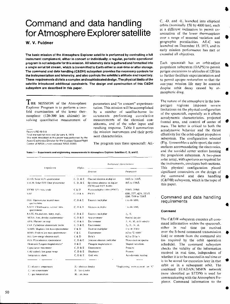
50
Command and data handling for Atmosphere Explorer satellite w. V. Fuldner
The basic mission of the Atmosphere Explorer satellite is performed by controlling a full instrument complement, either in concert or individually; a regular, periodic operati()nal program is not adequate for this mission. All telemetry data is gathered and formatted into a single serial bit stream, which is transmitted to Earth either in real-time or after storage. The command and data handling (C&DH) subsystem provides the necessary controls for the instrumentation and telemetry, and also controls the satellite's attitude and trajectory. These requirements dictate a complex and sophisticated design. The physical limits of the satellite introduced additional constraints. The design and construction of this C&DH subsystem are described in this paper.
THE MISSION of the Atmosphere Explorer Program is to perform a twofold examination of the lower thermosphere (120-300 km altitude) involving quantitative measurement of
Reprint RE-19-5-9 Final manuscript received January 4,1974 The work described in this paper was performed by the Astm-Electronics Division for the Goddard Space Flight Center of NASA under contract NAS5-23003.
parameters and "in concert" experimentation. This mission will be accomplished by a number of satellite-borne instruments performing correlative measurements of the chemical constituents, and of the solar input and resulting response. Table I summarizes the mission instruments and their pertinent characteristics.
The program uses three spacecraft: AE-
Table I - Experiments and engineering measurements in Atmosphere Explorer Satellites C, D, and E.
Experiment
ElJVS: Solar EUV spectrometer
LSlJM: Solar EUV filter photometer
lJVNO: UV nitric oxide
VAE
oss: Open-source neutral mass
spectrometer
N ACE: Closed-source neutral mass
spectrometer
N ATE: Neutral atm. temp. exp'l.
MESA: Atm. density accelerometer
RPA: Planner ion trap
CEP: Cylindrical electrostatic probe
M I MS: Magnetic ion mass spectrometer
BI MS: Positive ion mass spectrometer
lEE: Low-energy electron exp't.
PES: Photoelectron spectrometer
rhree-axis fluxgate magnetometer*
Capacitance manometer
Cold-cathode ion gauge range
I em perature alarm
r : electron temperature
I; : ion temperature'
I~ : gas temperature
Instrument chara{'feristics
FIiI?hts
Detector Parameters
C, D. & E Channel electron .multiplier 140A to 1850A
C, D, & E Spiraltron electron multiplier 40A to 1300A
(SEM) and EUV diodes
C&D Photomultiplier tubes (PMT 1) 215oA,2190A
c. 0 & E PMTs 6300,5577.4278,337IA 5200, 7319 to 7330A
C, D& E Electron multiplier Ito46AMU
C,D&E Electron multiplier It046AMU
C. 0 & E Electron multiplier 7~, N,
C. 0 & E Accelerometer Neutral density
C, 0& E Electrometer T" N" M" drift velocitl,l
C. D & E Electrometer '/~, .'I, .. .'I" M,
C&D Electron multiplier It046AMU
C&E Electrometer 0.5 to 72 AMU'
C&D SEM's 0.2 to 25 ke 'v
C, 0 & E Johnson electron multiplier Photo-electron spectra
D&E Fluxgate magnetometer Magnet variations
C. 0 & E Electrometer Pressure
C. 0 & E Diaphram Pressure
C.D&E Grid wire Aerodynamic heating
Nc : electron density
."', : ion density
*Engineering measurement on 'C'
M,: ion mass
C, -D, and -E, launched into elliptical orbits (nominally 150 by 4000 km), each at a different inclination to permit examination of the lower thermosphere over a range of seasonal variation and geographic peculiarities. AE-C was launched on December 15, 1973, and its early mission performance has met or exceeded all objectives.
Each spacecraft has an orbit-adjust propUlsion subsystem (OAPS) to permit perigee excursions to altitudes of 120 km to further facilitate experimentation and to permit apogee restoration so that the one-year mission life may be ensured despite orbit decay caused by atmospheric drag.
The nature of the atmosphere in the lowperigee regions imposes severe limitations on the physical configuration of the spacecraft, especially as it affects aerodynamic characteristics, projected frontal area, and control of center of mass, The latter is critical to both the aerodynamic behavior and the thrust effectivity for the orbit-adjust propUlsion subsystem, The configuration selected (Fig. I) resembles a cable spool, the outer surfaces accommodating the electronics, and the toroidal center section housing the propulsion SUbsystem, A two-piece solar array, with apertures as required for the instruments, envelopes both sections. This physical configuration placed significant constraints on the design of the command and data handling (C&DH) subsystem, which is the topic of this paper.
Command and data handling requirements
Command
The C&DH subsystem executes all command information within the spacecraft, either in real time (as received
•
•
•
•
•
•
•
over the S-band command transmission • link) or remote from the command site (as required by the orbit operation schedule). The command subsystem checks the validity of the information received in real time, independent of whether it is to be executed in real time or is to be stored for execution later in that orbit or in a subsequent orbit. The combined STADAN I MSFN network (now identified as STDN) is used for communicating with the Atmosphere Explorer. Command information to the
•
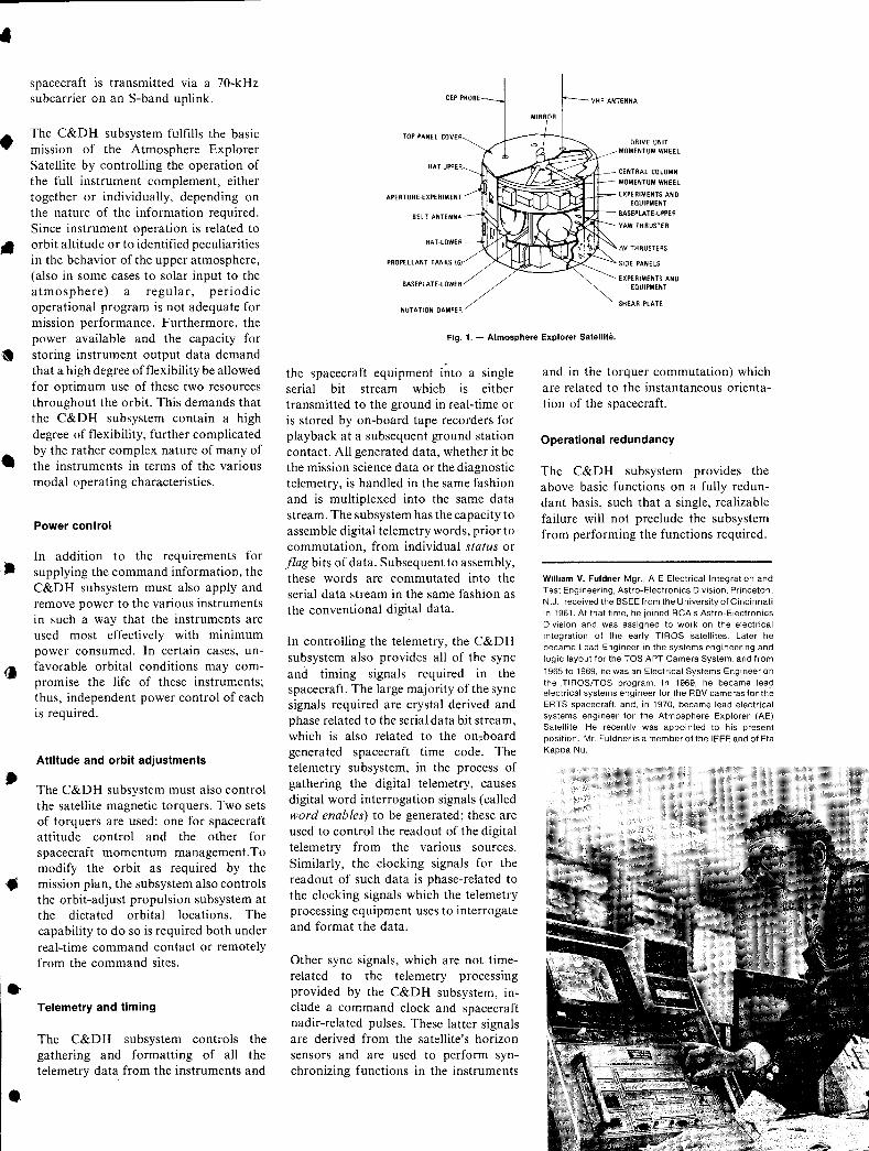
•
•
•
•
•
•
•
spacecraft is transmitted via a 70-kHz subcarrier on an S-band uplink.
The C&DH subsystem fulfills the basic mission of the Atmosphere Explorer Satellite by controlling the operation of the full instrument complement, either together or individually, depending on the nature of the information required. Since instrument operation is related to orbit altitude or to identified peculiarities in the behavior of the upper atmosphere, (also in some cases to solar input to the atmosphere) a regular, periodic operational program is not adequate for mission performance. Furthermore, the power available and the capacity for storing instrument output data demand that a high degree of flexibility be allowed for optimum use of these two resources throughout the orbit. This demands that the C&DH subsystem contain a high degree of flexibility, further complicated by the rather complex nature of many of the instruments in terms of the various modal operating characteristics.
Power control
In addition to the requirements for supplying the command information, the C&DH subsystem must also apply and remove power to the various instruments in such a way that the instruments are used most effectively with minimum power consumed. In certain cases, unfavorable orbital conditions may compromise the life of these instruments; thus, independent power control of each is required.
Attitude and orbit adjustments
The C&DH subsystem must also control the satellite magnetic torquers. Two sets of torquers are used: one for spacecraft attitude control and the other for spacecraft momentum management.To modify the orbit as required by the mission plan, the subsystem also controls the orbit-adjust propulsion subsystem at the dictated orbital locations. The capability to do so is required both under real-time command contact or remotely from the command sites.
Telemetry and timing
The C&DH subsystem controls the gathering and formatting of all the telemetry data from the instruments and
TOP PANel COVER
HAT·UPPER
DRIVE UNIT MOMENTUM WHEEL
CENTRAL COLUMN
APERTU RE·EXPER IMENT tt~~~~~~t-=ll:= MOMENTUM WHEEL L EXPERIMENTS AND
BelT ANTENN,6.
eOUIPMENT
""''Yrri;;:;.~00::'''~7t- BASEPLATE·UPPER
PROPELLANT TANKS 161
BASEPLATE·LOWER
NUTATION DAMPER
YAW THRUSTER
flV THRUSTERS
SIDE PANelS
EXPERIMENTS AND EQUIPMENT
SHEAR PLATE
Fig. 1. - Atmosphere Explorer Satellite.
the spacecraft equipment into a single serial bit stream which is either transmitted to the ground in real-time or is stored by on-board tape recorders for playback at a subsequent ground station contact. All generated data, whether it be the mission science data or the diagnostic telemetry, is handled in the same fashion and is multiplexed into the same data stream. The subsystem has the capacity to assemble digital telemetry words, prior to commutation, from individual status or .flag bits of data. Subsequent to assembly, these words are commutated into the serial data stream in the same fashion as the conventional digital data.
In controlling the telemetry, the C&DH subsystem also provides all of the sync and timing signals required in the spacecraft. The large majority of the sync signals required are crystal derived and phase related to the serial data bit stream, which is also related to the on"board generated spacecraft time code. The telemetry subsystem, in the process of gathering the digital telemetry, causes digital word interrogation signals (called word enables) to be generated; these are used to control the readout of the digital telemetry from the various sources. Similarly, the clocking signals for the readout of such data is phase-related to the clocking signals which the telemetry processing equipment uses to interrogate and format the data.
Other sync signals, which are not timerelated to the telemetry processing provided by the C&DH subsystem, include a command clock and spacecraft nadir-related pulses. These latter signals are derived from the satellite's horizon sensors and are used to perform synchronizing functions in the instruments
and in the torquer commutation) which are related to the instantaneous orientation of the spacecraft.
Operational redundancy
The C&DH subsystem provides the above basic functions on a fully redundant basis, such that a single, realizable failure will not preclude the subsystem from performing the functions required.
William V. Fuldner Mgr., A E Electrical Integration and Test Engineering, Astra-Electronics Division, Princeton, N.J., received the BSEEfrom the University of Cincinnati in 1961. At that time, he joined RCA's Astro-Electronics Division and was assigned to work on the electrical Integration of the early TIROS satellites. Later he became Lead Engineer in the systems engineering and logic layout for the TOS APT Camera System, and from
1965 to 1969, he was an Electrical Systems Engineer on the .TIROS/TOS program. In 1969, he became lead electrical systems engineer for the RBV cameras for the ERTS spacecraft, and, in 1970, became lead electrical systems engineer for the Atmosphere Explorer (A E) Satellite. He recently was appointed to his present position. Mr. Fuldner is a member of the IEEE and of Eta Kappa Nu.
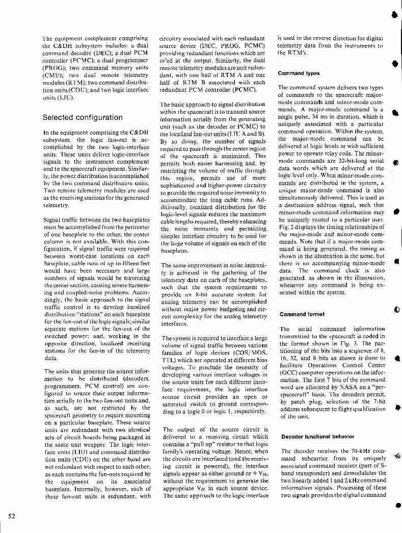
52
The equipment complement comprising the C&DH subsystem includes: a dual command decoder (DEC); a dual PCM controller (PCMC); a dual programmer (PROG); two command memory units (CMU); two dual remote telemetry modules (RTM); two command distribution units (CDU); and two logic interface units (LIU).
Selected configuration
In the equipment comprising the C&DH subsystem, the logic fan-out is accomplished by the two logic-interface units. These units deliver logic-interface signals to the instrument complement and to the spacecraft equipment. Similarly, the power distribution is accomplished by the two command distribution units. Two remote telemetry modules are used as the receiving stations for the generated telemetry.
Signal traffic between the two baseplates must be accomplished from the perimeter of one baseplate to the other; the center column is not available. With this configuration, if signal traffic were required between worst-case locations on each baseplate, cable runs of up to fifteen feet would have been necessary and large numbers of signals would be traversing the center section, causing severe harnessing and coupled-noise problems. Accordingly, the basic approach to the signal traffic control is to develop localized distribution "stations" on each baseplate for the fan-out of the logic signals; similar separate stations for the fan-out of the switched power; and, working in the opposite direction, localized receiving stations for the fan-in of the telemetry data.
The units that generate the source information to be distributed (decoders, programmers, PCM control) are configured to source their output information serially to the two fan-out units and, as such, are not restricted by the spacecraft geometry to require mounting on a particular baseplate. These source units are redundant with two identical sets of circuit boards being packaged in the same unit wrapper. The logic interface units (LIU) and command distribution units (CDU) on the other hand are not redundant with respect to each other, as each contains the fan-outs required by the equipment on its associated baseplate. Internally, however, each of these fan-out units is redundant, with
circuitry associated with each redundant source device (DEC, PROG, PCMC) providing redundant functions which are or'ed at the output. Similarly, the dual remote telemetry modules are unit redundant, with one half of RTM A and one half of R TM B associated with each redundant PCM controller (PCMC).
The basic approach to signal distribution within the spacecraft is to transmit source information serially from the generating unit (such as the decoder or PCMC) to the localized fan-out units (LIU A and B). By so doing, the number of signals required to pass through the center region of the spacecraft is minimized. This permits both easier harnessing and, by restricting the volume of traffic through this region, permits use of more sophisticated and higher-power circuitry to provide the required noise immunity to accommodate the long cable runs. Additionally, localized distribution for the logic-level signals reduces the maximum cable lengths required, thereby enhancing the noise immunity and permitting simpler interface circuitry to be used for the large volume of signals on each of the baseplates.
The same improvement in noise immunity is achieved in the gathering of the telemetry data on each of the baseplates, such that the system requirement to provide an 8-bit accurate system for analog telemetry can be accomplished without major power budgeting and circuit complexity for the analog telemetry interfaces.
The system is required to interface a large volume of signal traffic between various families of logic devices (COS/MOS, TTL) which are operated at different bias voltages. To preclude the necessity of developing various interface voltages in the source units for each different interface requirement, the logic interface source circuit provides an open or saturated switch to ground corresponding to a logic 0 or logic I, respectively.
The output of the source circuit is delivered to a receiving circuit which contains a "pull up" resistor to that logic family's operating voltage. Hence, when the circuits are interfaced (and the receiving circuit is powered), the interface signals appear as either ground or + V bb,
without the requirement to generate the appropriate V bb in each source device. The same approach to the logic interface
is used in the reverse direction for digital telemetry data from the instruments to the RTM's.
Command types
The command system delivers two types of commands to the spacecraft: majormode commands and minor-mode commands. A major-mode command is a single pulse, 34 ms in duration, which is uniquely associated with a particular command operation. Within the system, the major-mode command can be delivered at logic levels or with sufficient power to operate relay coils. The minormode commands are 32-bit-Iong serial data words which are delivered at the logic level only. When minor-mode commands are distributed in the system, a unique major-mode command is also simultaneously delivered. This is used as a destination address signal, such that minor-mode command information may be uniquely routed to a particular user. Fig. 2 displays the timing relationships of the major-mode and minor-mode commands. Note that if a major-mode command is being generated, the timing as shown in the illustration is the same, but there is no accompanying minor-mode data. The command clock is also generated, as shown in the illustration, whenever any command is being executed within the system.
Command format
The serial command information transmitted to the spacecraft is coded in the format shown in Fig. 3. The partitioning of the bits into a sequence of 8, 16, 32, and 8 bits as shown is done to facilitate Operations Control Center (OCC) computer operations on the information. The first 7 bits of the command word are allocated by NASA on a "perspacecraft" basis. The decoders permit, by patch plug, selection of the 7-bit address subsequent to flight qualification of the unit.
Decoder functional behavior
The decoder receives the 70-kHz command subcarrier from its uniquely associated command receiver (part of Sband transponder) and demodulates the two linearly added 1 and 2 kHz command information signals. Processing of these two signals provides the digital command
•
•
•
•
•
•
•
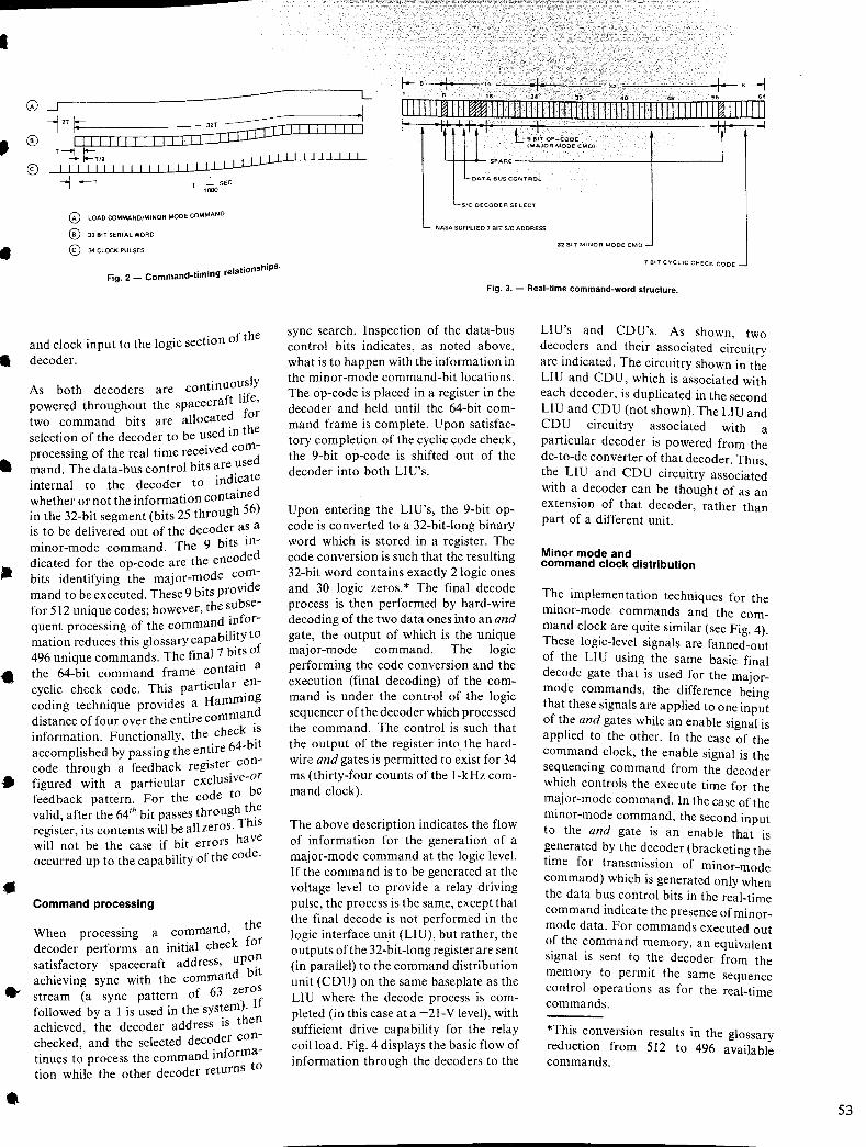
•
•
•
•
•
•
•
..
•
•
G) -1r---------------------------------------~L
--i 2T 1---. ---- ·1
~ .", '. :1 'n I e ---j
~ IIIII m III WWlIIIIIIIIIIIIIII n IIIIII n 111111 ii IIIIII r~ IIIII Ii I lEI I 1·'1· L •• !ToP-cooE
I It' I· ·1 I I--r-- :; 32T ------rro:::co I I ~. ~ . II I I I I I II I II I I I I I I I I I I
(MAJOR MODE CMOI ® T ---I t--~ I--T/2 .• I I I LI I I I I I I I I IIIIIIIIIIIIIIIIII~
SPARE -------------+-------1 DATA BUS CONTROL --I I--T ,
T=_SEC ",00
o LOAD COMMAND/MINOR MODE COMMAND
o 32 BIT SERIAL WORD
® 34 CLOCK PULSES
Fig. 2 _ Command-timing relationshiPS.
and clock input to the logic section of the
decoder.
As both decoders are continuously powered throughout the spacecraft life, two command bits are allocated for selection of the decoder to be used in the processing of the real time received command. The data-bus control bits are used internal to the decoder to indicate whether or not the information contained in the 32-bit segment (bits 25 through 56) is to be delivered out of the decoder as a minor-mode command. The 9 bits indicated for the op-code are the encoded bits identifying the major-mode command to be executed. These 9 bits provide for 512 unique codes; however, the subsequent processing of the command information reduces this glossary capability to 496 unique commands. The final 7 bits of the 64-bit command frame contain a cyclic check code. This particular encoding technique provides a Hamming distance of four over the entire command information. Functionally, the check ~s accomplished by passing the entire 64-bl
t
code through a feedback register configured with a particular exclusive-or feedback pattern. For the code to be valid, after the 64th bit passes through t~e register, its contents will be all zeros. ThiS will not be the case if bit errors have occurred up to the capability of the code.
Command processing
When processing a command, the decoder performs an initial check for satisfactory spacecraft address, upo~ achieving sync with the command bit stream (a sync pattern of 63 zeros followed by a 1 is used in the system). If achieved, the decoder address is then checked, and the selected decoder continues to process the command information while the other decoder returnS to
SIC DECODER SELECT
L-. NASA SUPPLIED 7 BIT SIC ADDRESS
32 BIT MI NOR MODE CMO _
7 BIT CYCLIC CHECK CODE _
Fig. 3. - Real-time command-word structure.
sync search. Inspection of the data-bus control bits indicates, as noted above, what is to happen with the information in the minor-mode command-bit locations. The op-code is placed in a register in the decoder and held until the 64-bit command frame is complete. Upon satisfactory completion of the cyclic code check, the 9-bit op-code is shifted out of the decoder into both LIU's.
Upon entering the LIU's, the 9-bit opcode is converted to a 32-bit-long binary word which is stored in a register. The code conversion is such that the reSUlting 32-bit word contains exactly 2 logic ones and 30 logic zeros. * The final decode process is then performed by hard-wire decoding of the two data ones into an and gat~, the output of which is the unique major-mode command. The logic performing the code conversion and the execution (final decoding) of the command is under the control of the logic sequencer of the decoder which processed the command. The control is such that the output of the register into the hardwire and gates is permitted to ~xist for 34 ms (thirty-four counts of the I-kHz command clock).
The above description indicates the flow of information for the generation of a major-mode command at the logic level. If the command is to be generated at the voltage level to provide a relay driving pulse, the process is the same, except that the final decode is not performed in the logic interface unit (LIU), but rather, the outputs of the 32-bit-long register are sent (in parallel) to the command distribution unit (COU) on the same baseplate as the LIU where the decode process is completed (in this case at a -2l-V level), with sufficient drive capability for the relay coil load. Fig. 4 displays the basic flow of information through the decoders to the
LIU's and COU's. As shown, two dec~de:s and their associated circuitry are mdlcated. The circuitry shown in the LIU and COU, which is associated with each decoder, is duplicated in the second LIU and ~O~ (not shown). The LIU and CO~ circUitry associated with a particular decoder is powered from the dc-to-dc converter of that decoder Th th.e LIU and COU circuitry ass~cia~~ With a. decoder can be thought of as an extensIOn ~f that decoder, rather than part of a different unit.
Minor mode and command clock distribution
T~e implementation techniques for the mmor-mode commands and the command cloc.k are quite similar (see Fig. 4). These logic-level signals are fanned-out of the LI U using the same b . f· aSlc mal decode gate that is used for the . maJor-mode com~ands, the difference being that these Signals are appll·ed to . onemput of the and gates while an enable signal is apphed to the other. In the case of the comma~d clock, the enable signal is the sequencmg command from the d d . eco er wh~ch controls the execute time for the major-mode command. In the case of the mmor-mode command, the second input to the and gate is an enable that is generated by the decoder (bracketing the time for transmission of . mmor-mode command) which is generated only when the data bus control bits in the real-tO
d. . Ime
comman mdlcate the presence of minor-mode data. For commands executed out o.f the ~ommand memory, an equivalent Signal IS sent to the decoder from the memory to permit the same sequence control operations as for the real-time commands.
*This conversion results in the gl d . ossary re uctlOn from 512 to 496 available commands .
53
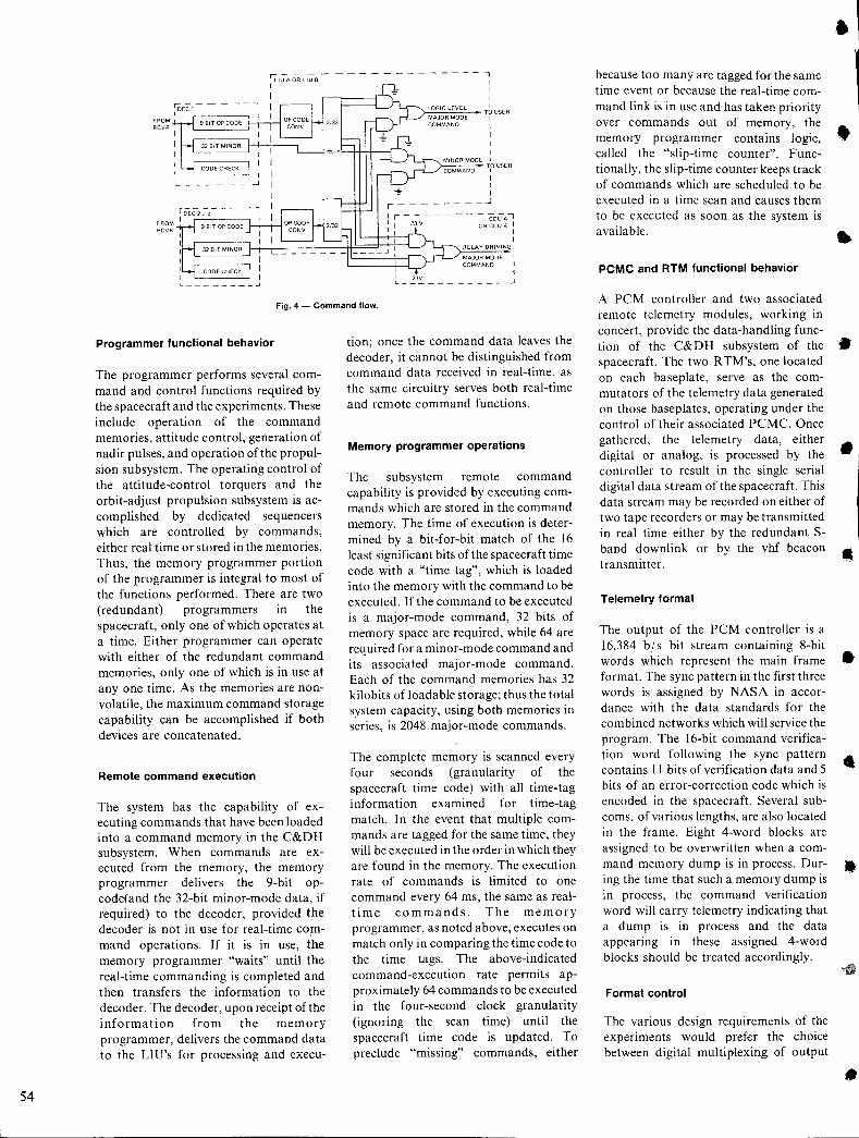
54
FROM RCVR
-------------,
I )-'C=..:::..:~- TO USER
I
Fig. 4 - Command flow.
Programmer functional behavior
The programmer performs several command and control functions required by the spacecraft and the experiments. These include operation of the command memories, attitude control, generation of nadir pulses, and operation of the propulsion subsystem. The operating control of the attitude-control torquers and the orbit-adjust propulsion subsystem is accomplished by dedicated sequencers which are controlled by commands, either real time or stored in the memories. Thus, the memory programmer portion of the programmer is integral to most of the functions performed. There are two (redundant) programmers in the spacecraft, only one of which operates at a time. Either programmer can operate with either of the redundant command memories, only one of which is in use at anyone time. As the memories are nonvolatile, the maximum command storage capability can be accomplished if both devices are concatenated.
Remote command execution
The system has the capability of executing commands that have been loaded into a command memory in the C&DH subsystem. When commands are executed from the memory, the memory programmer delivers the 9-bit opcode(and the 32-bit minor-mode data, if required) to the decoder, provided the decoder is not in use for real-time command operations. If it is in use, the memory programmer "waits" until the real-time commanding is completed and then transfers the information to the decoder. The decoder, upon receipt of the information from the memory programmer, delivers the command data to the LIU's for processing and cxecu-
tion; once the command data leaves the decoder, it cannot be distinguished from command data received in real-time. as the same circuitry serves both real-time and remote command functions.
Memory programmer operations
The subsystem remote command capability is provided by executing commands which are stored in the command memory. The time of execution is determined by a bit-for-bit match of the 16 least significant bits of the spacecraft time code with a "time tag", which is loaded into the memory with the command to be executed. If the command to be executed is a major-mode command, 32 bits of memory space are required, while 64 are required for a minor-mode command and its associated major-mode command. Each of the command memories has 32 kilobits of loadable storage; thus the total system capacity, using both memories in series, is 2048 major-mode commands.
The complete memory is scanned every four seconds (granularity of the spacecraft time code) with all time-tag information examined for time-tag match. In the event that mUltiple commands are tagged for the same time, they will be executed in the order in which they are found in the memory. The execution rate of commands is limited to one command every 64 ms, the same as realtime commands. The memory programmer, as noted above, executes on match only in comparing the time code to the time tags. The above-indicated command-execution rate permits approximately 64 commands to be executed in the four-second clock granularity (ignoring the scan time) until the spacecraft time code is updated. To preclude "missing" commands, either
because too many are tagged for the same time event or because the real-time command link is in use and has taken priority over commands out of memory, the memory programmer contains logic, called the "slip-time counter". Functionally, the slip-time counter keeps track of commands which are scheduled to be executed in a time scan and causes them to be executed as soon as the system is available.
PCMC and RTM functional behavior
A PCM controller and two associated remote telemetry modules, working in concert, provide the data-handling function of the C&DH subsystem of the spacecraft. The two R TM's, one located on each baseplate, serve as the commutators of the telemetry data generated on those baseplates, operating under the control of their associated PCMC. Once gathered, the telemetry data, either digital or analog, is processed by the controller to result in the single serial digital data stream of the spacecraft. This data stream may be recorded on either of two tape recorders or may be transmitted in real time either by the redundant Sband downlink or by the vhf beacon transmitter.
Telemetry format
The output of the PCM controller is a 16,384 bls bit stream containing 8-bit words which represent the main frame format. The sync pattern in the first three words is assigned by NASA in accordance with the data standards for the combined networks which will service the program. The 16-bit command verification word following the sync pattern contains I I bits of verification data and 5 bits of an error-correction code which is encoded in the spacecraft. Several subcoms, of various lengths, are also located in the frame. Eight 4-word blocks are assigned to be overwritten when a command memory dump is in process. During the time that such a memory dump is in process, the command verification word will carry telemetry indicating that a· dump is in process and the data appearing in these assigned 4-word blocks should be treated accordingly.
Format control
The various design requirements of the experiments would prefer the choice between digital multiplexing of output
•
•
•
•
•
•
..
•
•
•
•
•
•
..
•
•
telemetry data and/ or reception of digital word-enable signals on either separate or common lines for the different telemetry words generated within a unit. The digital word-enables are logic-level sync signals which are transmitted to the various telemetry source units to indicate that the telemetry word is to be read out of the unit. These signals will either be 8-, 16-, or 24-bit periods long, depending on the length of the word to be interrogated.
The telemetry format is controlled by a read-only memory (ROM) in the PCM controller. The configuration of the controller is such that only the ROM must be be changed from mission to mission.
In responding to the information contained in the ROM word, the PCM controller first identifies which remote telemetry module will be in use for the upcoming telemetry data and whether that data will be digital or analog when received. The digital contiguous indication is provided such that the basic generated "word enables" will be continuous over the N-multiple (N=2, 3) 8-bit words. This facility is used to handle the 16- and 24-bit long digital telemetry words which appear in the telemetry format.
Additional information in the ROM controls subcom selection and also contains information for the generation of wordunique digital interrogation signals (i. e., the "word-enables").
RTM gate addressing and digital word-enable generation
When a digital word-enable is transmitted to a source unit, the appropriate receiving gate must be opened in the remote telemetry module. This may be the same gate which is used for other digital telemetry words from the same source unit or may be a different gate, depending on the instrument design.
The digital word-enables are generated and fanned out in exactly the same manner as the major-mode commands described earlier. The PCM controller is the source of a 9-bit word which is transmitted to the logic interface unit for code conversion into a 32-bit word with exactly 2 logic ones and 30 logic zeros. The final decode from this register is accomplished in the same fashion as the major-mode command. The timing of the word-enable, while being decoded, is
under control of the PCM controller in use.
For conditions where there is a "one-forone" correspondence between use of a digital word-enable and gate from the remote telemetry module (RTM), the 9 bits in the ROM-stored word are used to generate both the word-enable and the RTM gate address. If the same RTM gate is to be used for different word-enables, information in the ROM word is used to address a separate small ROM in the PCM controller which generates the RTM gate address. Thus, the system design requirement to allow instrument choice is accomplished.
Analog vs. digital telemetry
Two types of input gating circuits are used in the RTM's in the system, one for digital information and the other for analog information (either positive or negative analogs). The digital input gate employs a "pull-up" resistor to the operating voltage in the RTM such that the digital interface technique requiring that the source unit supply only an open or saturated state to ground switch for logic zeros and ones respectively is maintained. The analog gate includes additional filtering capacity to provide satisfactory noise immunity for the analog signals.
Time-base configuration
The spacecraft is configured with two redundant countdown chains in each logic interface unit (LlU), one each associated with one of the two redundant crystal oscillators in the system. The design of the system is such that one of the two oscillators (one located in each LlU) supplies the input to two countdown chains associated with it (one in each LlU) to provide the frequencies required on the LlU's baseplate.
Only one of the redundant countdown chains in each LlU is in operation at any one time, although both crystal oscillators are continuously powered. Because of the large number of fannedout frequencies required on each baseplate, this configuration was chosen to minimize the inter-baseplate harnessing of high frequencies. To ensure that the proper phase relationship is generated between like signals on the two baseplates, a closed-loop phaselock is main-
tained between the two parallel countdown chains.
The output configuration of the timebase generated signals is such that the same approach to output redundancy coupling is used as that for the command clock signals. In this case, the time base that has been selected applies an input to one of the two inputs to anand gate, while the particular frequency to be outputted is applied to the other. The output coupling configurations for all signals at or below 16,384 b / s are so coupled and utilize the ground or open output signal configuration with the pull-up resistor in the receiving circuit. For high-speed signals, either localized or from baseplate to baseplate, the high-speed interface is used.
Sync generation
In the paragraphs dealing with the PCM controller, it was stated that the sync signals required by the experiments are primarily related to the generation and control of the digital telemetry. All of these signals are related back to the time base which forms the clock standard for all operations of the PCM controller. All of these operations are related to the spacecraft 24-bit time code, such that time correlation for operation of the experiments and synchronization of remote command execution are also available.
Summary
This paper has touched briefly on the various functions performed in the C&DH subsystem for Atmosphere Explorer satellites. It should be noted that the design of the subsystem is such that it is readily amenable to addition and modification should new command, sinc, or telemetry allocation be required. The localized "station" concept for interfacing and the standarized approach to interfaces provide adequate noise immunity and a high degree of versatility. While the satellite requires two sets of such stations, the subsystem is not limited to this number; additional stations may be added by using spare bits in the command-word structure and ROM word structure. As these data-source locations (PCMC, DEC) utilize highspeed interfaces to the local stations, much larger systems may utilize the same basic subsystem with no modification to the basic design.
55
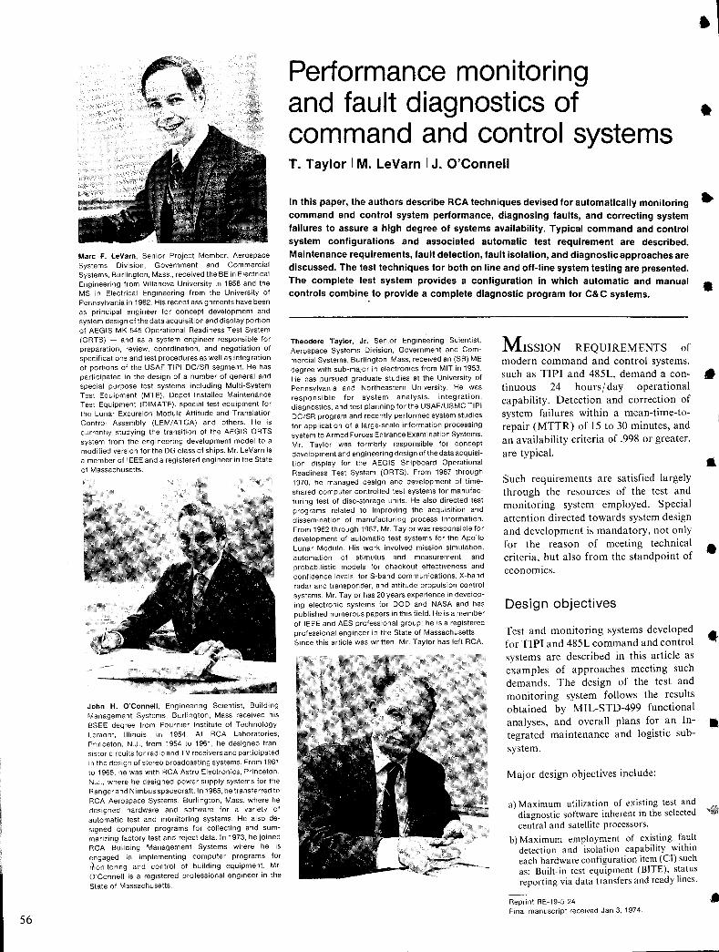
56
Marc F. LeVarn. Senior Project Member. Aerospace Systems Division, Government and Commercial Systems. Burlington, Mass .. received the BE in Electrical Engineering from Villanova University in 1958 and the MS in Electrical Engineering from the University of Pennsylvania in 1962. His recent assignments have been as principal engineer for concept development and system design of the data acquisition and display portion of AEGIS MK-545 Operational Readiness Test System (ORTS) - and as a system engineer responsible for preparation, review, coordination, and negotiation of specifications and test procedures as well as integration of portions of the USAF TIPI DC/SR segment. He has participated in the design of a number of general and special purpose test systems including Multi-System Test Equipment (MTE), Depot Installed Maintenance Test Equipment (DIMATE), special test equipment for the Lunar Excursion Module Attitude and Translation Control Assembly (LEM/ATCA) and others. He is currently studying the transition of the AEGIS ORTS system from the engineering development model to a modified version for the DG class of ships. Mr. LeVarn is a member of IEEE and a registered engineer in the State of Massachusetts.
John H. O'Connell, Engineering Scientist, Building Management Systems, Burlington, Mass received his BSEE degree from Fournier Institute of Technology, Lemont, Illinois, in 1954. At RCA Laboratories, Princeton, N.J., from 1954 to 1961, he designed transistor circuits for radio and TV receivers and participated in the design of stereo broadcasting systems. From 1961 to 1965, he was with RCA Astra Electronics, Princeton, N.J., where he designed power supply systems for the Ranger and Nimbus spacecraft. In 1965, he transferred to RCA Aerospace Systems, Burlington, Mass. where he designed hardware and software for a variety of automatic test and monitoring systems. He also desIgned computer programs for collecting and summarizing factory test and reject data. In 1973, he joined RCA Building Management Systems where he is engaged in implementing computer programs for rtJonitoring and control of building equipment. Mr. O'Connell is a registered professional engineer in the
State of Massachusetts.
• Performance monitoring and fault diagnostics of • command and control systems T. Taylor I M. LeVarn I J. O'Connell
In this paper, the authors describe RCA techniques devised for automatically monitoring command and control system performance, diagnosing faults, and correcting system failures to assure a high degree of systems availability. Typical command and control system configurations and associated automatic test requirement are described. Maintenance requirements, fault detection, fault isolation, and diagnostic approaches are discussed. The test techniques for both on line and off-line system testing are presented. The complete test system provides a configuration in which automatic and manual controls combine to provide a complete diagnostic program for C&C systems.
Theodore Taylor, Jr. Senior Engineering Scientist, Aerospace Systems Division, Government and Commercial Systems, Burlington, Mass, received an (SB) ME degree with sub-major in electronics from MIT in 1953. He has pursued graduate studies at the University of Pennsylvania and Northeastern University. He was responsible for system analysis, integration, diagnostics, and test planning forthe USAF/USMC TIPI DC/SR program and recently performed system studies for application of a large-scale information processing system to Armed Forces Entrance Examination Systems. Mr. Taylor was formerly responsible for concept development and engineeringdesign of the data acquisition display for the AEGIS Shipboard Operational Readiness Test System (ORTS). From 1967 through 1970, he managed design and development of timeshared computer controlled test systems for manufacturing test of disc-storage units. He also directed test programs related to improving the acquisition and dissemination of manufacturing process information. From 1962 through 1967, Mr. Taylorwas responsible for development of automatic test systems for the Apollo Lunar Module. His work involved mission simulation, automation of stimulus and measurement, and probabilistic models for checkout effectiveness and confidence levels, for S-band communications, X-band radar and transponder, and attitude propulsion control systems. Mr. Taylor has 20 years experience in developing electronic systems for DOD and NASA and has published numerous papers in this field. He is a member of IEEE and AES professional group; he is a registered professional engineer in the State of Massachusetts. Since this article was written, Mr. Taylor has left RCA.
MISSION REQUIREMENTS of modern command and control systems, such as TIPI and 485L, demand a continuous 24 hours( day operational capability. Detection and correction of system failures within a mean-time-torepair (MTTR) of 15 to 30 minutes, and an availability criteria of .998 or greater, are typical.
Such requirements are satisfied largely through the resources of the test and monitoring system employed. Special attention directed towards system design and development is mandatory, not only for the reason of meeting technical criteria, but also from the standpoint of economics.
Design objectives
Test and monitoring systems developed for TIPI and 485L command and control systems are described in this article as examples of approaches meeting such demands. The design of the test and monitoring system follows the results obtained by MIL-STD-499 functional analyses, and overall plans for an Integrated maintenance and logistic subsystem.
Major design objectives include:
a) Maximum utilization of existing test and diagnostic software inherent in the selected central and satellite processors.
b) Maximum employment of existing fault detection and isolation capabihty withm each hardware configuration item (el) such as: Built-in test equipment (BITE). status reporting via data transfers and ready lines.
Reprint RE-19-5-24 Final manuscript received Jan 3, 1974.
•
•
•
•
•
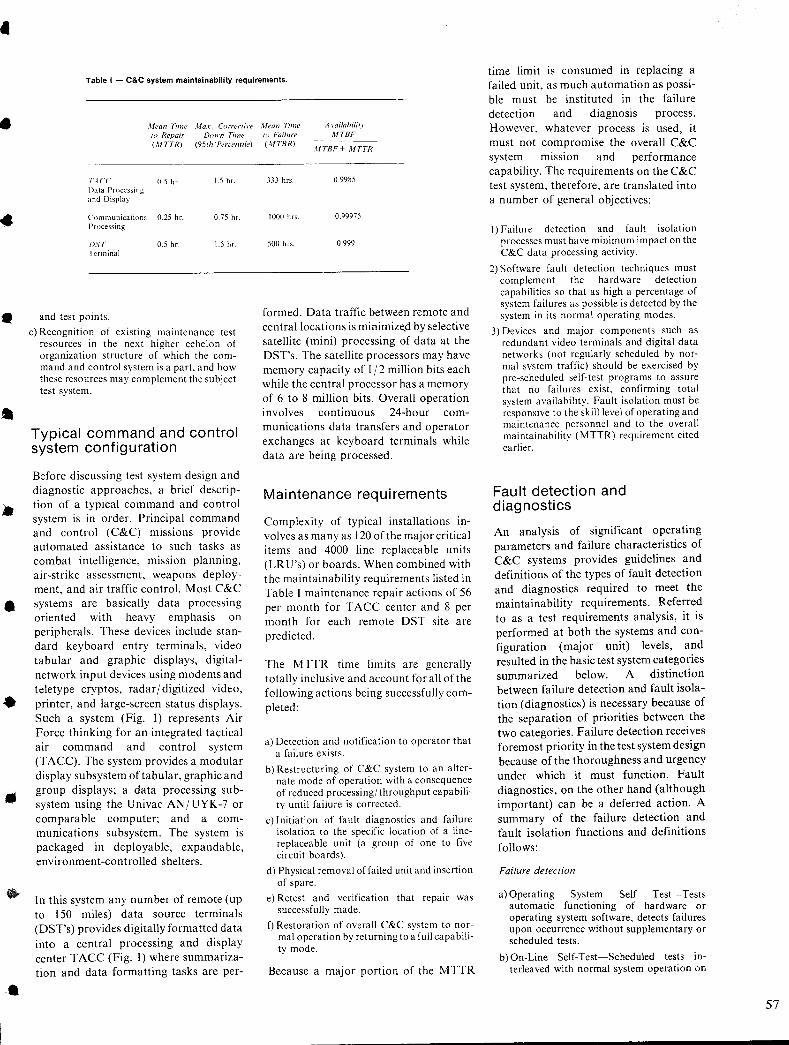
•
..
•
•
•
•
Table I - C&C system maintainability requirements.
,\lean Time Jlax. Correoi\'e .Wean Time A \'oilahiliry MTBF 10 Repair Down Time 10 Failure
(.I1TTR) (95t" 'Percentile) (.IITBR) .\lTBF + .I1TTR
t>I CC 0.5 hr I.S hr. Data Processing and Display
Communications 0.25 hr. 0.75 hr. Processing
f)ST 0.5 hr. I.S hr. I crminal
and tesl points .
c) Recognition of existing maintenance test resources in the next higher echelon of organization structure of which the command and control system is a part, and how these resources may complement the subject test system.
Typical command and control system configuration
Before discussing test system design and diagnostic approaches, a brief description of a typical command and control system is in order. Principal command and control (C&C) missions provide automated assistance to such tasks as combat intelligence, mission planning, air-strike assessment, weapons deployment, and air traffic control. Most C&C systems are basically data processing oriented with heavy emphasis on peripherals. These devices include standard keyboard entry terminals, video tabular and graphic displays, digitalnetwork input devices using modems and teletype cryptos, radar / digitized video, printer, and large-screen status displays. Such a system (Fig. I) represents Air Force thinking for an integrated tactical air command and control system (TACC). The system provides a modular display subsystem of tabular, graphic and group displays; a data processing subsystem using the Univac AN/UYK-7 or comparable computer; and a communications subsystem. The system is packaged in deployable, expandable, environment-controlled shelters.
In this system any number of remote (up to 150 miles) data source terminals (DST's) provides digitally formatted data into a central processing and display center T ACC (Fig. I) where summarization and data formatting tasks are per-
333 hrs. 0.9985
1000 hrs. 0.99975
500 hrs. 0.999
formed. Data traffic between remote and central locations is minimize.d by selective satellite (mini) processing of data at the DST's. The satellite processors may have memory capacity of 1/2 million bits each while the central processor has a memory of 6 to 8 million bits. Overall operation involves continuous 24-hour communications data transfers and operator exchanges at keyboard terminals while data are being processed.
Mai ntenance req u i rements
Complexity of typical installations involves as many as 120 of the major critical items and 4000 line replaceable units (LR U's) or boards. When combined with the maintainability requirements listed in Table I maintenance repair actions of 56 per month for T ACC center and 8 per month for each remote DST site are predicted.
The MTTR time limits are generally totally inclusive and account for all of the following actions being successfully completed:
a) Detection and notification to operator that a failure exists.
b) Restructuring of C&C system to an alternate mode of operation with a consequence of reduced processing/ throughput capability until failure is corrected.
c) Initiation of fault diagnostics and failure isolation to the specific location of a linereplaceable unit (a group of one to five circuit boards).
d) Physical removal offailed unit and insertion of spare.
e) Retest and verification that repair was successfully made.
f) Restoration of overall C&C system to normal operation by returning to a full capability mode.
Because a major portion of the MTTR
time limit is consumed in replacing a failed unit, as much automation as possible must be instituted in the failure detection and diagnosis process . However, whatever process is used, it must not compromise the overall C&C system miSSIOn and performance capability. The requirements on the C&C test system, therefore, are translated into a number of general objectives:
I) Failure detection and fault isolation processes must have minimum impact on the C&C data processing activity.
2) Software fault detection techniques must complement the hardware detection capabilities so that as high a percentage of system failures as possible is detected by the system in its normal operating modes.
3) Devices and major components such as redundant video terminals and digital data networks (not regularly scheduled by normal system traffic) should be exercised by pre-scheduled self-test programs to assure that no failures exist, confirming total system availability. Fault isolation must be responsive to the skill level of operating and maintenance personnel and to the overall maintainability (MTTR) requirement cited earlier.
Fault detection and diagnostics
An analysis of significant operating parameters and failure characteristics of C&C systems provides guidelines and definitions of the types of fault detection and diagnostics required to meet the maintainability requirements. Referred to as a test requirements analysis, it is performed at both the systems and configuration (major unit) levels, and resulted in the basic test system categories summarized below. A distinction between failure detection and fault isolation (diagnostics) is necessary because of the separation of priorities between the two categories. Failure detection receives foremost priority in the test system design because of the thoroughness and urgency under which it must function. Fault diagnostics, on the other hand (although important) can be a deferred action. A summary of the failure detection and fault isolation functions and definitions follows:
Failure detection
a) Operating System Self Test-Tests automatic functioning of hardware or operating system software, detects failures upon occurrence without supplementary or scheduled tests.
b) On-Line Self-Test-Scheduled tests interleaved with normal system operation on
57
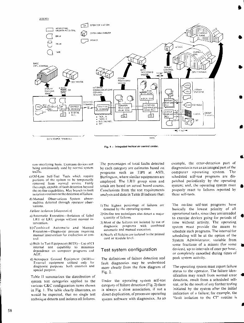
58
LEGENDS:
GJ OPERATOR STATION
CJ ADDITIONAL GROWTH POTENTIAL
0 ~ EXPENDABLE SHELTER
DRISK
B D PRINTER
DRUM
0 TAPE
DASC
O~Ps.eENTRAL """ ~
"" ~ lOST SHELTER
DISPLAY • ALCE, ST ATiONS TUoe, OR -DAse 15A>C
DATA SOURCE TERMINALS
non-interfering basis. Exercises devices not being continuously used by normal system traffic.
c) Off-Line Self-Test--Tests which require portions of the sys'tem to be tern porarily removed from normal service. Fairly thorough, capable of fault detection beyond the on-line capabilities. May branch to fault isolation routines on the detection offailure.
d) Manual Observations-System abnormalities detected through operator observations.
Failure isolation (diagnostics)
a) Automatic Execution·-Isolation of failed LR U or LR U groups without manual intervention.
b) Combined Automatic and Manual Execution-Diagnostic process requlflng manual intervention for evaluation or control.
c) Built In Test Equipment (BITE)-Use of CI internal test capability to mmimize dependence on computer programs and AGE.
d) Aerospace Ground Equipment (AGE)External equipment utilized only for diagnostic purposes-both common and special purpose.
Table II summarizes the distribution of system test categories applied to the various C&C configuration items shown in Fig. I. The table clearly illustrates, as would be expected, that no single test technique detects and isolates all failures.
: 6~g:;~ NET. L-____ ---l '-------'
• TTY
TAce
Fig. 1 - Integrated tactical air control center.
The percentages of total faults detected by each category are estimates based on programs such as TIPI at ASD, Burlington, where similar equipments are employed. The LRU group sizes and totals are based on actual board counts. Conclusions from the test requirements analysis and data in Table II indicate that:
I) The highest percentage of failures are detected by the operating system.
2) On-line test techniques also detect a major quantity of failures.
3) Most of the failures are isolated by use of diagnostic programs with combined automatic and manual execution.
4) Nearly all failures are isolated to the printed card or module level.
Test system configuration
The definitions of failure detection and fault diagnostics may be understood more clearly from the flow diagram of Fig. 2.
Under the operating system self-test category of failure detection (Fig. 2) there is always a close association, if not a direct duplication, of processor operating system software with diagnostics. As an
CONSOLI l DISPLAYS
)
GROUP
......, '250' I--
example, the error-detection part of diagnostics is run as an integral part of the computer operating system. The scheduled self-test programs are dispatched periodically by the operating system; and, the operating system must properly react to failures reported by these self-tests.
The on-line self-test programs have basically the lowest priority of all operational tasks, since they are intended to exercise devices going for periods of time without activity. The operating system must provide the means to schedule such programs. The interval for scheduling will be at the option of the System Administrator, variable from some fractions of a minute (for some devices), up to intervals of once per hour, or completely cancelled during times of peak system activity.
The operating system must report failure status to the operator. The failure identification may result from normal error detection, result from a scheduled selftest, or be the result of any further testing initiated by the system after the initial indication of a failure; for example, the "fault isolation to the CI" routine is
•
•
•
•
•
•
•
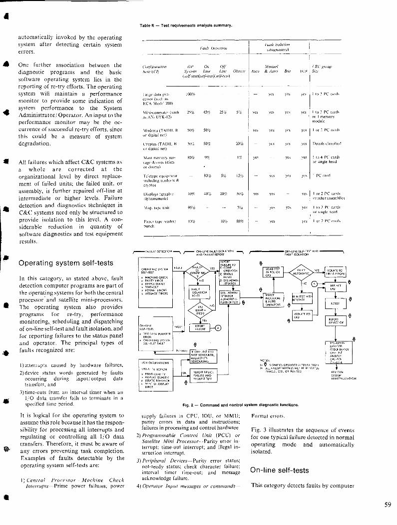
•
•
..
•
•
•
•
automatically invoked by the operating system after detecting certain system errors.
One further association between the diagnostic programs and the basic software operating system lies in the reporting of re-try efforts. The operating system will maintain a performance monitor to provide some indication of system performance to the System Administrator / Operator. An input to the performance monitor may be the occurrence of successful re-try efforts, since this could be a measure of system degradation.
All failures which affect C&C systems as a whole are corrected at the organizational level by direct replacement of failed units; the failed unit, or assembly, is further repaired off-line at intermediate or higher levels. Failure detection and diagnostics techniques in C&C systems need only be structured to provide isolation to this level. A considerable reduction in quantity of software diagnostics and test equipment results.
Operating system self-tests
In this category, as stated above, fault detection computer programs are part of the operating systems for both the central processor' and satellite mini-processors. The operating system also provides programs for re-try, performance monitoring,. scheduling and dispatching of on-line self-test and fault isolation, and for reporting failures to the status panel and operator. The principal types of faults recognized are:
1) interrupts caused by hardware failures,
2) device status words generated by faults occurring during input/ output data transfers, and
3) time-outs from an interval timer when an I/O data transfer fails to terminate in a specified time period.
It is logical for the operating system to assume this role because it has the responsibility for processing all interrupts and regulating or controlling all I/O data transfers. Therefore, it must be aware of any errors preventing task completion. Examples of faults detectable by the operating system self-tests are:
I) Celllral Processor-Machine Check Illlerrupts-Prime power failures; power
Table II - Test requirements analysis summary.
('()'~fiKura{ion
Item (en
Large data pro-ccssor (such as RCA Model 200)
Mini-computer (such as AN UYK-12)
Vlodcms (TADIL B or digital net)
Cryptos (TADI!. B or digital net)
Mass memory sto-rage devices (discs or drums)
I detype equipment 1 nduding modems & cryptos
Displays (graphic alphanumeric)
Mag. tape unit
Paper tape rcader/ punch
OPERATING SYSTEM SELF-TEST
o MACHINE CHECK o PARITY ERROR o DEVICE STATUS o TIME-OUT o FORMAT ERRORS o MESSAGEERRQRS
ON-LINE SELF-TESTS
o TEST DATA TRANSFER ERROR OPERATING SYSTEM SELF-TEST FAULT
USER OBSERVATIONS
VISUAL DETECTION
o PRINT QUALITY o DISPLAY QUALITY
ERRATIC BEHAVIOR PRINT OR DISPLAY ERROR
Fuul! Derecrion
OP 0" Off System Line Line
(,,If'lesl)(self-lesl)(self'lesl)
100y,
259( 45<}( 2Yir
509c SQf/r
30<;( 50l)c
90% 9%
80% 5%
100'i 400'( 2OCi(
95(j{
IO'!C 10(H,
Ohsen'
59(
20%
1%
IY!C
300'(-
5%
80%
Auto
yes
yes
yes
yes
Faull isolalion (dioJ{flOSlics)
.\fonual & Auto Bite
yes yes
yes yes
yes yes
yes yes
yes
yes yes
yes
yes yes
yes
IR( group ,I0'E Si=e
yes I to 3 PC card~
yes I to 3 PC cards or I memory module
yes I or 2 PC cards
yes Details classified
yes I to 4 PC cards or single head
yes I PC card
yes I or 2 PC cards or other assem blies
yes I to 3 PC cards or single head
yes I or 2 PC cards
,------OFF-LINE SELF-TEST AND ---__ FAULT ISOLATION
NOTES:
1) ~ SIGNIFIES OPERATOR INTERVENTION 2) ALL FAILURE REPORTS Will BE BY STATUS
PANELS, CRT, OR PRINTERS PERFORM SYSTEM REINITIAlIZAT!ON
Fig. 2 - Command a,nd control system diagnostic functions.
supply failures in CPU, IOU, or MMU; parity errors in data and instructions; failures in processing and control hardware.
2) Programmable Control Unit (PCU) or Saleilite Mini Processor-Parity error In
terrupt; time-out interrupt; and illegal In
struction interrupt.
3) Peripheral Devices-Parity error status; not-ready status; check character failure; interval timer time-out; and message acknowledge failure.
4) Operator Input messages or commands-
Format errors.
Fig. 3 illustrates the sequence of events for one typical failure detected in normal operating mode and automatically isolated.
On-line self-tests
This category detects faults by computer
59
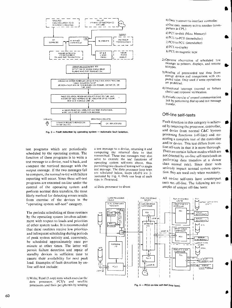
60
r - ---;A~RE- - -l I COI..JTROlLER ELECTRONICS MTU I (CE) CARD L ______ _
RESULTS
r - ---, I !DEL~~I~~~il~N :
'--__ ......J L ___ -1
r -FA~R;--l I STATUS I
'--___ --' L _D~l~_J
OPERATING SYSTEM SELF TEST
DETECTION OF DEVICE ST ATUS ERROR DURING MAG TAPE TRANSACTION
OPERATING SYSTEM SCHEDULES ON-UNE FAULT ISOLATION PROGRAM "FAULT ISOLATION TO (I"
(REASON-FAULT MAY BE IN INTERFACE CONTROLLER, OR TAPE CE f OR TAPE UNIT)
FAULT ISOLATION PROGRAWi5 ISOLATES fAULT TO TAPE UNIT. NATURE OF FAULT HAPPENS TO BE INDICATIVE OF C£ FAILURE,
AND CE IS 6, SINGLE CARD LRU
r------'------~ PERMISSION GRANTED
OP. REPLACESlRU
Fig. 3 - Fault detection by operating system - automatic fault isolation.
test programs which are periodically scheduled by the operating system. The function of these programs is to write a test message to a device, read it back, and compare the received message with the output message. If the two messages fail to compare, the normal re-try with failure reporting will occur. Since these self-test programs are executed on-line under the control of the operating system and perform normal data transfers, the most likely method for detecting errors results from exercise of the devices in the "operating system self-test" category.
a test message to a device, returning it and comparing the returned data to that transmitted. These test messages may also serve to execute the test functions of operating system self-tests above, thus permitting two classes of testing with a single test message. The data processor loop tests are tabulated below, loops (d)-(h) are illustrated by Fig. 4. Only one loop of each type is illustrated.
The periodic scheduling of these routines by the operating system involves adjustment with respect to loads and priorities of other system tasks. It is recommended that these routines receive low priorities and infrequent scheduling during periods of peak system activity and, conversely, be scheduled approximately once per minute at other times. The latter will permit failure detection and repair of standby devices in sufficient time to ensure their availability for next peak load. Examples of fault detection by online self-test include:
a) Data processor-to-drum
COMM PROCESSING SHELTER
DUAL COMM DATA PROCESSOR
OAT A PROCESSING SHELTER
DUAL INTERFACE CONTROLLER
b) Data processor-to-interface controller
clOne main memory unit to another (companson in CPU)
d) PCU-to-disk (Mass Memory)
e) PCU-to-PCU (intrashelter)
1) PCU-to-PCU (intershelter) g) PCU-to-display
h) PCU-to-magnetic tape
2) Operator observation of scheduled test messages to printers, displays, and remote teletypes.
3) Reading of prerecorded test data from storage devices and comparison with expected value. Only used if write operations are prohitited.
4) Intentional interrupt (normal or failure check) and response verification.
S) Periodic exercise of unused communication link by performing dial up and test message transfer.
Off-line self-tests
Fault detection in this category is achieved by removing the processor, controller, and device from normal C&C System processing functions (off-line) and executing a complete test of the controller andj or device. This test differs from online self-tests in that it is more thorough. There are certain failure modes which are not detected by on-line self-tests (such as performing data transfers at a slower than normal rate). Since these tests seriously impact normal system operation, they are used only when necessary.
All on-line self-tests have counterpart tests run off-line. The following are examples of unique off-line tests:
DISPLAY CONTROL DISK SHELTER
DISPLAY ST ATtON CONTROLLER
I) Writej Read (Loop) tests which exercise the data processor, PCU's and satellite processors and their peripherals by sending Fig. 4 - PCU on-line self-test (loop type).
•
•
.. •
•
•
•
•
•
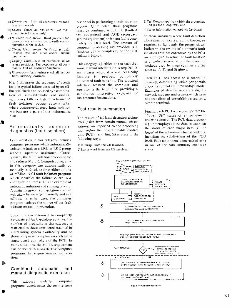
•
..
•
..
•
a) Teleprinters-Print all characters, respond to all commands.
b) Drums-Check all bits at "I" and "0". (Unprotected tracks only)
c) Prepared Test Media-Read pre-recorded paper or mag tapes in order to verify correct operation of the device.
d) Timing Measurement-Verify correct data transfer rate and other critical timing parameters.
e) Display Units-Test all characters in all screen positions. Test response to all commands. Test all keyboard functions.
/) Processors-Test routines check all instructions, memory locations.
Fig. 5 illustrates the sequence of events for one typical failure detected by an offline self-check and isolated by a combination of semi-automatic and manual techniques. Off-line tests often branch to fault isolation routines automatically, where computer-directed fault isolation routines are a part of the maintenance plan.
Automatically executed diagnostics (fault isolation)
Fault isolation in this category includes computer programs which automatically isolate the fault to a LRU or LRU group without operator assistance. Consequently, the fault isolation process is fast and reduces MTTR. Computer programs in this category are automatically or manually initiated, and run either on-line or off-line. A CI fault isolation program which identifies the failure source to a configuration item (CI) is an example of automatic initiation and running on-line. A main memory fault isolation routine will likely be initiated manually and run off-line. In either case, the computer program isolates the source of the fault without manual intervention.
Since it is uneconomical to completely automate all fault isolation routines, the number of programs in this category is restricted to those considered essential in maintaining system availability and/ or those fairly easy to implement such as the single-board controllers of the PCU. In many situations, the MTTR requirement can be met with cost-effective computer programs that require manual intervention.
Combined automatic and manual diagnostic execution
This category includes computer programs which assist the maintenance
personnel in performing a fault isolation process. Quite often, these programs must be combined with BITE (built-in test equipment) and AGE (aerospace ground equipment) to isolate faults completely to LRU level. The amount of computer processing aid provided is a function of the complexity of the fault isolation branch.
This category is justified on the basis that some manual intervention is required in many cases where it is not technically feasible to perform completely automated fault isolation. The principal interface between the computer and operator is the teleprinter, providing a continuous interactive exchange of maintenance instructions. .
Test results summation
The results of all fault-detection techniques (aside from certain manual observations) are reported to the processing unit within the programmable control unit (PCU); reporting takes place in the following ways:
I) Interrupt from the CE involved,
2) Status word from the CE involved,
3) Test Data comparison within the processing unit (as for a loop test), and
4) Status information entered via keyboard.
In those instances where fault detection alone does not locate a fault to the degree required to light only the proper status indicator, the results of automatic fault isolation routines controlled by the PCU are employed to refine the fault location prior to display generation. The reporting methods used by these routines are the same as I), 2), and 3) above.
Each PCU has access to a record in memory, determining which peripherals under its control are in "standby" mode. Examples of standby mode are digitalnetwork modems and cryptos which have not been directed to establish a circuit to a remote terminal.
Finally, each PCU receives a report of the "Power Off' status of all equipment under its control. The PCU data processing unit employs all the data to establish the status of each major item (CI or lower) of the subsystem which it controls, including the subdivisions of the PCU itself. Each major item is determined to be in one of the four mutually exclusive states.
PCU (AN/UYK-12) INSTRUCTlON TEST
COMM. PROCESSOR OR DATA SOURCE TERMINAL OAT A PROCESSOR
r-----' I FAILURE: I
PROCESSOR I ,,-~~R'::.T~"-)
r------, I RESULTS, I
FAULT DETECTION I INDICATlON I .... _______ .J
SYSTEM UPON MANUAL COMMAND
LOAD TEST PROGRAM INTO COMPUTER VIA PAPER TAPE READER
TEST PROGRAM CHECKS All INSTRUCTIONS CONTlNUQUSl Y WILL HAL T UPON ERROR (LET RUN I MIN.)
FAULT DETECTION RETURN TO NORMAL SYSTEM OPERATION
USE O&MPANEL TO DETERMINE MEMORY LOCATION OF INSTRUCTION 8EING EXECUTED AT TIME OF HALT
USE MANUALS AND AGE (WITH LOOPED PROGRAM) IF NECESSARY TO ISOLATE FAULT
Fig. 5 - Off-line self-tests .
61
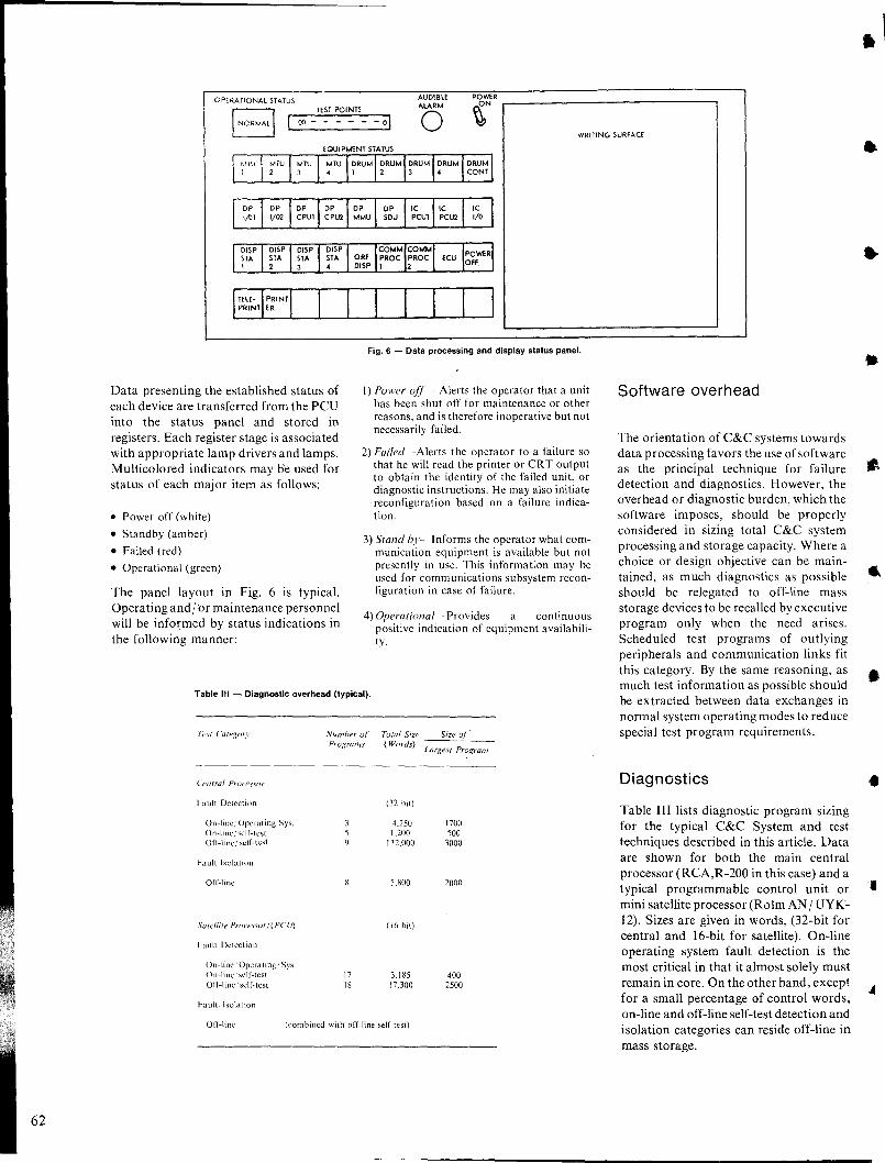
62
CPERATlONAl STATUS TEST POINTS
AUDIBLE ALARM POWER r--------------------------------, ~N
00- - 01 o WRITING SURFACE
Data presenting the established status of each device are transferred from the peu into the status panel and stored in registers. Each register stage is associated with appropriate lamp drivers and lamps. Multicolored indicators may be used for status of each major item as follows:
• Power off (white)
• Standby (amber)
• Failed (red)
• Operational (green)
The panel layout in Fig. 6 is typical. Operating and/br maintenance personnel will be informed by status indications in the following manner:
I I Fig. 6 - Data processing and display status panel.
I) Power 0/(- Alerts the operator that a unit has been shut off for maintenance or other reasons, and is therefore inoperative but not necessarily failed.
2) Failed-Alerts the operator to a failure so that he will read the printer or CRT output to obtain the identity of the failed unit, or diagnostic instructions. He may also initiate reconfiguration based on a failure indication.
3) Stand by-Informs the operator what communication equipment is available but not presently in use. This information may be used for communications subsystem reconfiguration in case of failure.
4) Operational-Provides a continuous positive indication of equipment availability.
Table III - Diagnosllc overhead (typical).
('(,l1lral Pr()('es.wr
l-ault Detection
On-line/Operating Sys. On-line,' self-test Off-line' self-test
hlUit Isolation
Off-line
Salel/ite Prucessor/(PCU)
Fault Detection
On-line Operating Sys. On-line self-test Off-line self-test
Fault Isolation
Numher of' Total Size Size of
Program.~· (Words) La/xes! Program
(32 bit)
4.250 1700 1.200 500
132,000 3000
5.800 2000
(16 bil)
17 3.185 400 18 17.300 2500
Off·line (combined with off-line self test)
Software overhead
The orientation of C&C systems towards data processing favors the use of software as the principal technique for failure detection and diagnostics. However, the overhead or diagnostic burden, which the software imposes, should be properly considered in sizing total C&C system processing and storage capacity. Where a choice or design objective can be maintained, as much diagnostics as possible should be relegated to off-line mass storage devices to be recalled by executive program only when the need arises. Scheduled test programs of outlying peripherals and communication links fit this category. By the same reasoning, as much test information as possible should be extracted between data exchanges in normal system operating modes to reduce special test program requirements.
Diagnostics
Table III lists diagnostic program sizing for the typical C&C System and test techniques described in this article. Data are shown for both the main central processor (RCA,R-200 in this case) and a typical programmable control unit or mini satellite processor (Rolm AN / UYK-12). Sizes are given in words, (32-bit for central and 16-bit for satellite). On-line operating system fault detection is the most critical in that it almost solely must remain in core. On the other hand, except for a small percentage of control words, on-line and off-line self-test detection and isolation categories can reside off-line in mass storage.
•
•
•
•
•
•
•
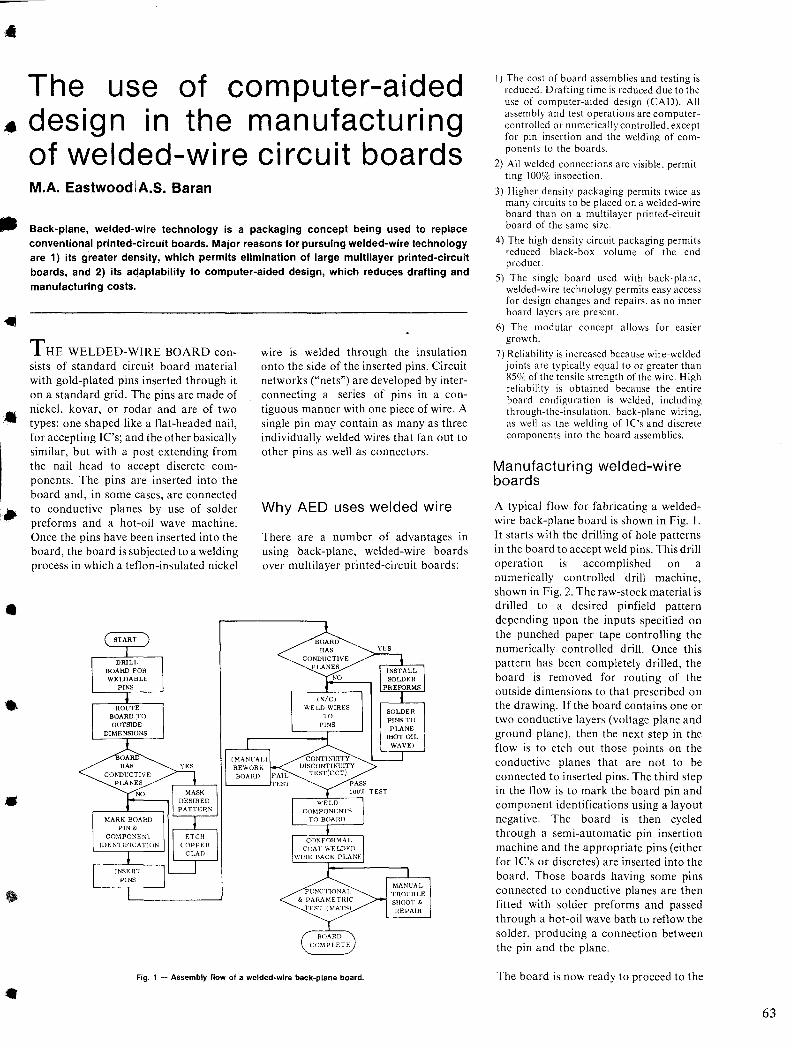
•
..
..
•
•
•
•
The use of computer-aided design in the manufacturing of welded-wire circuit boards M.A. EastwoodIA.S. Baran
Back-plane, welded-wire technology is a packaging concept being used to replace conventional printed-circuit boards. Major reasons for pursuing welded-wire technology are 1) its greater density, which permits elimination of large multilayer printed-circuit boards, and 2) its adaptability to computer-aided design, which reduces drafting and manufacturing costs.
THE WELDED-WIRE BOARD consists of standard circuit board material with gold-plated pins inserted through it on a standard grid. The pins are made of nickel, kovar, or rodar and are of two types: one shaped like a flat-headed nail, for accepting IC's; and the other basically similar, but with a post extending from the nail head to accept discrete components. The pins are inserted into the board and, in some cases, are connected to conductive planes by use of solder preforms and a hot-oil wave machine. Once the pins have been inserted into the board, the board is subjected to a welding process in which a teflon-insulated nickel
wire is welded through the insulation onto the side of the inserted pins. Circuit networks ("nets") are developed by interconnecting a series of pins in a contiguous manner with one piece of wire. A single pin may contain as many as three individually welded wires that fan out to other pins as well as connectors.
Why AED uses welded wire
There are a number of advantages in using back-plane, welded-wire boards over multilayer printed-circuit boards:
BOARD HAS
WELD WIRES TO
PINS
FCNCT}ONAI, & PARAMETHIC
TEST (MATS)
SOLDER PINS TO PLANE
(HOT OIL WAVE)
MANUAL
TROUBLE SHOOT & HEPAIR
Fig. 1 - Assembly flow of a welded-wire back-plane board.
I) The cost of board assemblies and testing is reduced. Drafting time is reduced due to the use of computer-aided design (CAD). All assembly and test operations are computercontrolled or numerically controlled. except for pin insertion and the welding of components to the boards.
2) All welded connections are visible. permitting 100o/c inspection.
3) Higher density packaging permits twice as many circuits to be placed on a welded-wire board than on a multilayer printed-circuit board of the same size.
4) The high-density circuit packaging permits reduced black-box volume of the end product.
5) The single board used with back-plane. welded-wire technology permits easy access for design changes and repairs. as no inner board layers are present.
6) The modular concept allows for easier growth.
7) Reliability is increased because wire-welded joints are typically equal to or greater than 85% of the tensile strength of the wire. High reliability is obtained because the entire board configuration is welded. including through-the-insulation. back-plane wiring . as well as the welding of Ie's and discrete components into the board assemblies.
Manufacturing welded-wire boards
A typical flow for fabricating a weldedwire back-plane board is shown in Fig. I. It starts with the drilling of hole patterns in the board to accept weld pins. This drill operation is accomplished on a numerically controlled drill machine, shown in Fig. 2. The raw-stock material is drilled to a desired pinfield pattern depending upon the inputs specified on the punched paper tape controlling the numerically controlled drill. Once this pattern has been completely drilled, the board is removed for routing of the outside dimensions to that prescribed on the drawing. If the board contains one or two conductive layers (voltage plane and ground plane), then the next step in the flow is to etch out those points on the conductive planes that are not to be connected to inserted pins. The third step in the flow is to mark the board pin and component identifications using a layout negative. The board is then cycled through a semi-automatic pin insertion machine and the appropriate pins (either for lC's or discretes) are inserted into the board. Those boards having some pins connected to conductive planes are then fitted with solder preforms and passed through a hot-oil wave bath to reflow the solder, producing a connection between the pin and the plane.
The board is now ready to proceed to the
63
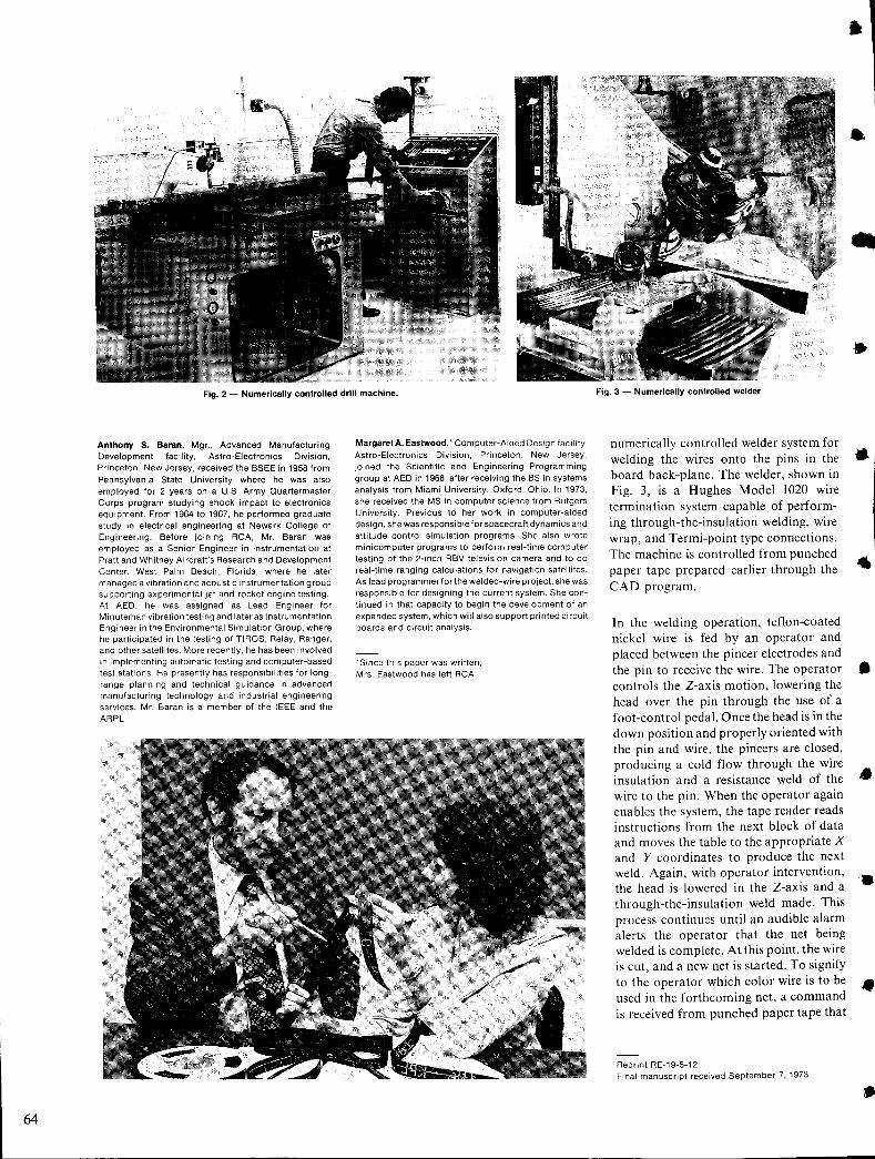
64
Fig. 2 - Numerically controlled drill machine.
Anthony S, Baran, Mgr., Advanced Manufacturing Development facility, Astro-Electronics Division, Princeton, New Jersey, received the BSEE in 1958 from Pennsylvania State University where he was also employed for 2 years on a U.S. Army Quartermaster Corps program studying shock impact to electronics equipment. From 1964 to 1967, he performed graduate study in electrical engineering at Newark College of Engineering. Before joining RCA, Mr. Baran was employed as a Senior Engineer in instrumentation at Pratt and Whitney Aircraft's Research and Development Center, West Palm Beach, Florida, where he later managed a vibration and acoustic instrumentation group supporting experimental jet and rocket engine testing. At AED, he was assigned as Lead Engineer for Minuteman vibration testing and later as Instrumentation Engineer in the Environmental Simulation Group, where he participated in the testing of TIROS, Relay, Ranger, and other satellites. More recently, he has been involved in implementing automatic testing and computer-based test stations. He presently has responsibilities for longrange planning and technical guidance in advanced manufacturing technology and industrial engineering services. Mr. Baran is a member of the IEEE and the ARPL.
Margaret A. Eastwood,' Computer-Aided Design facility, Astra-Electronics Division, Princeton, New Jersey, joined the Scientific and Engineering Programming group at AED in 1968, after receiving the BS in systems analysis from Miami University, Oxford, Ohio. In 1973, she received the MS in computer science from Rutgers University. Previous to her work in computer-aided design, she was responsible for spacecraft dynamics and attitude control simulation programs. She also wrote minicomputer programs to perform real-time computer testing of the 2-inch RBV television camera and to do real-time ranging calculations for navigation satellites. As lead programmer forthe welded-wire project, she was responsible for designing the current system. She continued in that capacity to begin the development of an expanded system, which will also support printed circuit boards and circuit analysis.
*Since this paper was written, Mrs. Eastwood has left RCA.
Fig. 3 - Numerically controlled welder
numerically controlled welder system for welding the wires onto the pins in the board back-plane. The welder, shown in Fig. 3, is a Hughes Model 1020 wire termination system capable of performing through-the-insulation welding, wire wrap, and Termi-point type connections. The machine is controlled from punched paper tape prepared earlier through the CAD program,
In the welding operation, teflon-coated nickel wire is fed by an operator and placed between the pincer electrodes and the pin to receive the wire. The operator controls the Z-axis motion, lowering the head over the pin through the use of a foot-control pedal. Once the head is in the down position and properly oriented with the pin and wire, the pincers are closed, producing a cold flow through the wire insulation and a resistance weld of the wire to the pin. When the operator again enables the system, the tape reader reads instructions from the next block of data and moves the table to the appropriate X and Y coordinates to produce the next weld. Again, with operator intervention, the head is lowered in the Z-axis and a through-the-insulation weld made. This process continues until an audible alarm alerts the operator that the net being welded is complete. At this point, the wire is cut, and a new net is started. To signify
•
..
•
•
•
..
•
to the operator which color wire is to be .. used in the forthcoming net, a command is received from punched paper tape that
Reprint RE-19-5-12 Final manuscript received September 7,1973
•
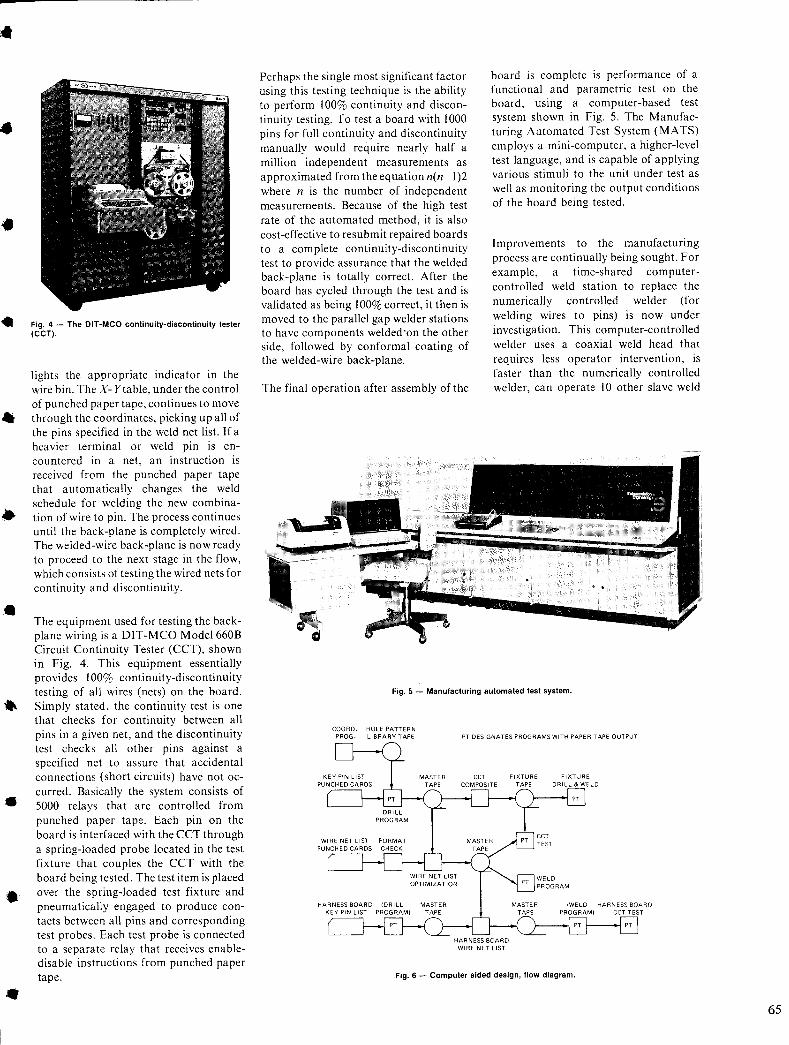
•
•
•
•
Fig. 4 - The OfT-MCa continuity-discontinuity tester (CCT).
lights the appropriate indicator in the wire bin. The X- Y table, under the control of punched paper tape, continues to move through the coordinates, picking up all of the pins specified in the weld net list. If a heavier terminal or weld pin is encountered in a net, an instruction is received from the punched paper tape that automatically changes the weld schedule for welding the new combination of wire to pin. The process continues until the back-plane is completely wired. The welded-wire back-plane is now ready to proceed to the next stage in the flow, which consists of testing the wired nets for continuity and discontinuity .
The equipment used for testing the backplane wiring is a DIT-MCO Model 660B Circuit Continuity Tester (CCT), shown in Fig. 4. This equipment essentially provides 100% continuity-discontinuity testing of all wires (nets) on the board. Simply stated, the continuity test is one that checks for continuity between all pins in a given net, and the discontinuity test checks all other pins against a specified net to assure that accidental connections (short circuits) have not occurred. Basically the system consists of 5000 relays that are controlled from punched paper tape. Each pin on the board is interfaced with the CCT through a spring-loaded probe located in the test fixture that couples the CCT with the board being tested. The test item is placed over the spring-loaded test fixture and pneumatically engaged to produce contacts between all pins and corresponding test probes. Each test probe is connected to a separate relay that receives enabledisable instructions from punched paper tape.
Perhaps the single most significant factor using this testing technique is the ability to perform 100% continuity and discontinuity testing. To test a board with 1000 pins for full continuity and discontinuity manually would require nearly half a million independent measurements as approximated from the equation n(n-I)2 where n is the number of independent measurements. Because of the high test rate of the automated method, it is also cost-effective to resubmit repaired boards to a complete continuity-discontinuity test to provide assurance that the welded back-plane is totally correct. After the board has cycled through the test and is validated as being 100% correct, it then is moved to the parallel gap welder stations to have components welded"on the other side, followed by conformal coating of the welded-wire back-plane.
The final operation after assembly of the
board is complete is performance of a functional and parametric test on the board, using a computer-based test system shown in Fig. 5. The Manufacturing Automated Test System (MATS) employs a mini-computer, a higher-level test language, and is capable of applying various stimuli to the unit under test as well as monitoring the output conditions of the board being tested.
Improvements to the manufacturing process are continually being sought. For example, a time-shared computercontrolled weld station to replace the numerically controlled welder (for welding wires to pins) is now under investigation. This computer-controlled welder uses a coaxial weld head that requires less operator intervention, is faster than the numerically controlled welder, can operate 10 other slave weld
Fig. 5 - Manufacturing automated test system.
COORD. PROG.
HOLE PATTERN LIBRARY TAPE PT DESIGNATES PROGRAMS WITH PAPER TAPE OUTPUT
HARNESS BOARD WI RE NET LIST
Fig. 6 - Computer aided design, flow diagram.
65
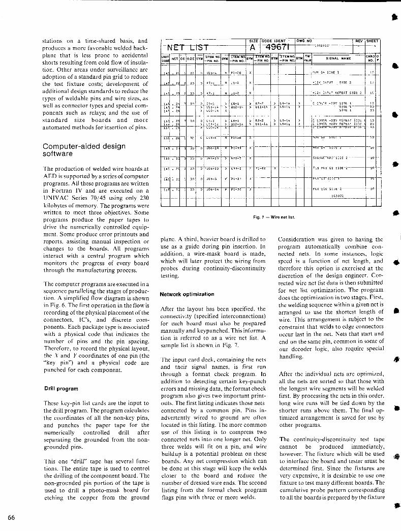
66
stations on a time-shared basis, and produces a more favorable welded backplane that is less prone to accidental shorts resulting from cold flow of insulation. Other areas under surveillance are adoption of a standard pin grid to reduce the test fixture costs; development of additional design standards to reduce the types of weldable pins and wire sizes, as well as connector types and special components such as relays; and the use of standard size boards and more automated methods for insertion of pins.
Computer-aided design software
The production of welded wire boards at AED is supported by a series of computer programs. All these programs are written in Fortran IV and are executed on a UNIV AC Series 70/45 using only 230 kilobytes of memory. The programs were written to meet three objectives. Some programs produce the paper tapes to drive the numerically controlled equipment. Some produce error printouts and reports, assisting manual inspection or changes to the boards. All programs interact with a central program which monitors the progress of every board through the manufacturing process.
The computer programs are executed in a sequence paralleling the stages of production. A simplified flow diagram is shown in Fig. 6. The first operation in the flow is recording of the physical placement of the connectors, I C's, and discrete components. Each package type is associated with a physical code that indicates the number of pins and the pin spacing. Therefore, to record the physical layout, the X and Y coordinates of one pin (the "key pin") and a physical code are punched for each component.
Drill program
These key-pin list cards are the input to the drill program. The program calculates the coordinates of all the non-key pins, and punches the paper tape for the numerically controlled drill after separating the grounded from the nongrounded pins.
This one "drill" tape has several functions. The entire tape is used to control the drilling of the component board. The non-grounded pin portion of the tape is used to drill a photo-mask board for etching the copper from the ground
---------------------------~SO'I~ZE<~I'cNO~D~E~I~D~E~NT~-~inDWwG~_.N~O-_ ------------rl'"R~~7r.sMH~E~ET~'
t--Nt-;---t I ~ I ~ 1 -q~b ( I 97<50"---+-1---- ---4-
UNIT NET CC SIZE SYM ITEM NO. SYM ITEM NO SYM ITEM NO. SYM ITEM NO SVM TW COD -PIN NO. -PIN NO. -PIN NO. -PIN NO PAIR
SIGNAL N ..... E CJ:RD 0
NO. P
J---.lA-1---!--?2'1--"J-..13.!'.0J--.C0"-l-'U-'.!I2:5-:.'!4-+---,H'-l-'P,-,I~-20'!8-+-,X'-t-____ -+---1-____ -+--+---1~MUX (.4 SIDE 1 10
lA 2 2 30 o R7-1 M Jl-2 +12V INPUT SIDE 2 10
t-H-: . ~ 7 30 ~ e13~14 ~ ~}2~n- ~t{-~1~-~ ~};{~: C CONTR .. ZOV SI!)E 1 10 IDE--r--t-20
SloE 1 30 lA 2 > UIO-14 X
1-----1---I--I--+-+-----1----1------I---1----+-I-----l---1-+------ ------ r--- -lA 2 7 30 0 C?-1 > (8-1 > R2 ... 2 > ue ... 14 > C CONTR ... 20V REPEAT SIDE 10
~~-+ -t-~ *~~t~::-:~t~'-l---f-~+"-U,,12c:-l~~4'--1-~>+-"-Ul'-'1c:-l'-"4'--1-~>-+"'U9:.:.-"14'---J-::.-> -1---+~~~~gg~~!i ;!~ ~~
lA 2 1 30 0 U38-1A M Pl-S"3 -'X+----+--+----+--+--+...
lA 3 1 30 0 U38-14 ~ PT=5'o x
Fig. 7 - Wire net list.
plane. A third, heavier board is drilled to use as a guide during pin insertion. In addition, a wire-mask board is made, which will later protect the wiring from probes during continuity-discontinuity testing.
Network optimization
After the layout has been specified, the connectivity (specified interconnections) for each board must also be prepared manually and keypunched. This information is referred to as a wire net list. A sample list is shown in Fig. 7.
The input card deck, containing the nets and their signal names, is first run through a format check program. In addition to detec.ting certain key-punch errors and missing data, the format check program also gives two important printouts. The first listing indicates those nets connected by a common pin. Pins inadvertently wired to ground are often located in this listing. The more common use of this listing is to compress two connected nets into one longer net. Only three welds will fit on a pin, and wire buildup is a potential problem on these boards. Any net compression which can be done at this stage will keep the welds closer to the board and reduce the number of dressed wire ends. The second listing from the formal check program flags pins with three or more welds.
Consideration was given to having the program automatically combine connected nets. In some instances, logic speed is a function of net length, and therefore this option is exercised at the discretion of the design engineer. Corrected wire net list data is then submitted for net list optimization. The program does the optimization in two stages. First, the welding sequence within a given net is arranged to use the shortest length of wire. This arrangement is subject to the constraint that welds to edge connectors occur last in the net. Nets that start and end on the same pin, common in some of our decoder logic, also require special handling.
After the individual nets are optimized, all the nets are sorted so that those with the longest wire segments will be welded first. By processing the nets in this order, long wire runs will be tied down by the shorter runs above them. The final optimized arrangement is saved for use by other programs.
The continuity-discontinuity test tape cannot be produced immediately, however. The fixture which will be used to interface the board and tester must be determined first. Since the fixtures are very expensive, it is desirable to use one fixture to test many different boards. The cumulative probe pattern corresponding to all the boards is prepared by the fixture
.1
.:
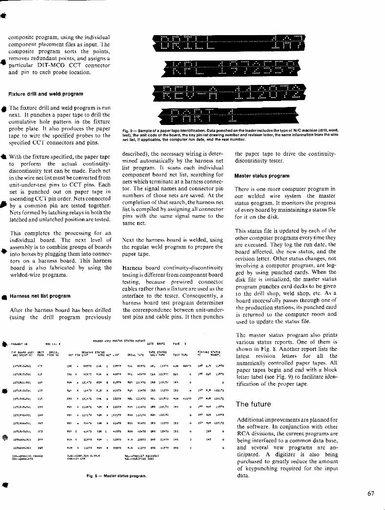
• composite program, using the individual component placement files as input. The composite program sorts the points, removes redundant points, and assigns a particular DIT-MCO CCT connector and pin to each probe location.
Fixture drill and weld program
• The fixture drill and weld program is run next. It punches a paper tape to drill the cumulative hole pattern in the fixture probe plate. It also produces the paper tape to wire the specified probes to the specified CCT connectors and pins.
• With the fixture specified, the paper tape to perform the actual continuitydiscontinuity test can be made. Each net in the wire net list must be converted from unit-under-test pins to CCT pins. Each net is punched out on paper tape in
•
ascending CCT pin order. Nets connected by a common pin are tested together. Nets formed by latching relays in both the latched and unlatched position are tested.
This completes the processing for an individual board. The next level of assembly is to combine groups of boards into boxes by plugging them into connectors on a harness board. This harness board is also fabricated by using the welded-wire programs.
• Harness net list program
After the harness board has been drilled (using the drill program previously
... ;:~~; .. ;:~~; .. ~~;:~ .. ; ...... ; ....................................... !:; .... !: ~:! .. ~~~~;. i ... = r:: .. .E •• L ... L... ..! .. r··i ::
· . .... . . ..................... . · . . . . ..... ... . .. .. . .. ..... . .. . .. .................................................................................. .. ..... . .... . ............ . .. .. ...... . · ... ...... . · .. ...... ...... . ..... .... .... .
·····1;;~:··1~~~~··1:::1··;;;;;··!;;;!···········J::··::L·):··i:::i··:7··:/··· .... . .... ..... . . . .. . .. .. ....... !;;;! .. !;;;! .. !;;;! .... ! ........... !.! ...................................... . : :::..: : . ..... . ....
Fig. 9 - Sa":,ple of a paper tape identification. Data punched on the leader includes the type of N/C machine (drill, weld, test), the unIt code of the board, the key pin list drawing number and revision leller, the same information from the wire net list, if applicable, the computer run date, and the reel number.
described), the necessary wiring is determined automatically by the harness net list program. It scans each individual component board net list, searching for nets which terminate at a harness connector. The signal names and connector pin numbers of those nets are saved. At the completion of that search, the harness net list is compiled by assigning all connector pins with the same signal name to the same net.
Next the harness board is welded, using the regular weld program to prepare the paper tape.
Harness board continuity-discontinuity testing is different from component board testing, because prewired connector cables rather than a fixture are used as the interface to the tester. Consequently, a harness board test program determines the correspondence between unit-undertest pins and cable pins. It then punches
the paper tape to drive the continuitydiscontinuity tester.
Master status program
There is one more computer program in our welded wire system-the master status program. It monitors the progress of every board by maintaining a status file for it on the disk.
This status file is updated by each of the other computer programs every time they are executed. They log the run date, the board affected, the new status, and the revision letter. Other status changes, not involving a computer program, are logged by using punched cards. When the disk file is initialized, the master status program punches card decks to be given to the drill shop, weld shop, etc. As a board successfully passes through one of the production stations, its punched card is returned to the computer room and used to update the status file.
., "HOED WIRE MASTER $TATUS REPORT
The master status program also prints various status reports. One of them is shown in Fig. 8. Another report lists the latest reVISIOn letters for all the numerically controlled paper tapes. All paper tapes begin and end with a block letter label (see Fig. 9) to facilitate identification of the proper tape.
PRO.lICT Ai 80X LJU 8 DATE '0)13
TOP BOARD ASS\" UNIT SERIAL DRAWING STATUS lAP! STATUS AND GROUP NO CODE FROM TO KEY PIN L1ST WIR.e NeT LIST DRILL TAPe weLD TAPe
z211913.501 '" CH' 8Z571 tH' t 11'''' VA~ eZ'''I'2 R'L 113'3
2Z11917.'01 'U, CH, . 40673 RUN • 40n3 R" lt06"1'3 D'S 121'''I'Z
ZZ'119Z1':'501 , .. RUN A 121lt"/'2 'CN • usn RUN 1Z1lt1Z 011 1Z21"Z
• zZ"I'l91'~501 '" RUN · 104'71 RUN , 216'1J RuN lo'+n OBS llzn
Z2:1192:8':'501 ," CH' · lZl't"/'2 tN< , ziln REL 12141Z m U15"1'Z
ZZ'11919.'01 '" RUN A 1116"1'Z 'UN , Z2zn RUN 1116"1'Z OBS lZ21 12
2Z'1930':"01 '" RUN A 112172 'UN , 122112 'UN 11Z112 'UN 1221 'T2
2Z'I'1906.'01 '" RUN 91472: 'UN , 216')') RUN 91472 0" 112n
Z2'1'192:'~'01 '" 'UN C 4tZ471 'UN , 425'1'1 RUN '+24't'3 OBS \1 lt 'l'3
ZZ"l'6064.501 '" 'UN C usn 'UN 1Z'13 'UN 2zsn 085 Zl6i3
2Z'T6065~501 ,., RUN · 11273 'UN , Jo.n RUN 11Z13 OBS usn
ECN ... ORA~INC CHANGE RUN--COHPUlER OUTPUT R.II. ... PRDOUCT RELEASeD OBS"·OBSOLeTE CHtl:--JN CP' VAL .... vERIFaD CODD
Fig. 8 - Master status program.
•
PAGE ,
nST TAPE
RUN JOlt"/')
0",
OBS
OBS
RUN 41073
OBS
OBS
OBS
OBS
085
'IXTURI IUTUS NO MANU',
,H' RUN 11'" ,H' 0.' 11""
,,, RUN 1211'2
,., RUN lZ21'Z
,,, 'UN lln,
,,, RUN lln)
,., RUN iZ21'l'2
015
0",
The future
Additional improvements are planned for the software. In conjunction with other RCA divisions, the current programs are being interfaced to a common data base, and several new programs are anticipated. A digitizer is also being purchased to greatly reduce the amount of keypunching required for the input data.
67
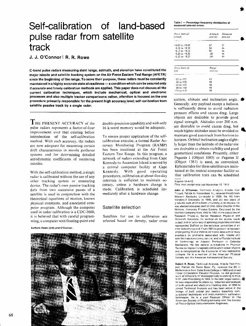
68
Self-calibration of land-based pulse radar from satellite track J.J.O'Connorl R.R.Rowe
C-band pulse radars measuring slant range, azimuth, and elevation have constituted the major missile and satellite tracking system on the Air Force Eastern Test Range (AFETR) since the beginning of the range. To serve their purpose, these radars must be constantly maintained in a highly accurate state of readiness - a condition which can be assured only if accurate and timely calibration methods are applied. This paper does not discuss all the current calibration techniques, which include mechanical, optical and electronic processes and also multiple tracker comparisons; rather, attention is focused on the one procedure primarily responsible for the present high accuracy level; self-calibration from satellite passive track by a single radar. .
T HE PRESENT ACCURACY of the pulse radars represents a factor-of-four improvement over that existing before introduction of the self-calibration method. With such accuracy, the radars are now adequate for measuring certain drift characteristics in missile guidance systems and for determining detailed aerodynamic coefficients of reentering missiles.
With the self-calibration method, a single radar is calibrated without the use of any other tracking system or measuring device. The radar's own passive tracking data from two successive passes of a satellite is used in conjunction with the theoretical equations of motion, known physical constants, and associated computer program. Although the computer used in radar calibration is a CDC-3600, it is believed that with careful programming, a computer with floating-point and
Authors Rowe (left) and O'Connor.
double-precision capability and with only 16 k-word memory would be adequate.
To ensure proper application of the selfcalibration exercise, a formal Radar Accuracy Monitoring Program (RAMP) has been instituted at the Air Force Eastern Test Range. In this program, a network of radars extending from Cape Kennedy to Ascension Island is served by a central computer facility at Cape Kennedy. With good operating procedures, calibration at about five-day intervals is sufficient to maintain accuracy, unless a hardware change is made. Calibration is scheduled Immediately after a hardware change.
Satell ite selection
Satellites for use in calibration are selected based on density, radar cross
Table I - Percentage frequency distribution of measured zero-set errors.
t:rror interval Azimuth Elevalion (mrad) zero-se( zero-seT
-0.05 to +0.05 67 53 -0.10 to +0.10 94 86 -0.15 to +0.15 99 96 -0.20 to +0.20 100 98 -0.25 to +0.25 100 99
Error inrerval Range (Ii) zero-seT
-15 to +15 65 -30 to +30 88 -45 to +45 96 -60 to +60 98 -75 to +75 98
•
•
section, altitude and inclination angle. • Generally, any payload except a balloon is sufficiently dense to avoid radiation pressure effects and excess drag. Large objects are desirable to provide good signal strength. Altitudes over 200 n.m. are desirable to avoid excess drag, but much higher altitudes must be avoided to maintain good auto track from horizon to horizon. Orbital inclination angles slight-ly larger than the latitude of the radar site are desirable to obtain visibility and good geometrical conditions. Presently, either Pegasus I (Object 1085) or Pegasus II .. (Object 1381) is used, as convenient. Ephemerides for these satellites are maintained at the central computer facility so that calibration tests can be scheduled
Reprint 19-4-12 Final manuscript received November 13, 1973
John J. O'Connor, Technical AnalYSiS, Missile Test • I Project, Patrick Air Force Base, FL, received the BS from Western Kentucky University in 1939, the MS from Vanderbilt University in 1940, and did two years of graduate work at Ohio State University, all in physics. He was elected vice-preSident of Ohio State Chapter of the National Honorary PhysiCS SOCiety. Employed by the DuPont Company from 1942 to 1961 in the capacities of Research Physicist, Senior Research Physicist and Research Associate, he worked on the atomic bomb ~ project and on accuracy of spinning projectiles and also represented DuPont on the technical committee of an inter-industry council. From 1961 to present he has been employed by RCA at Patrick Air Force Base with primary emphasis on problems associated with missile and satellite trajectory computations, and by Florida Institute of Technology as Adjunct Professor in Celestial Mechanics. He has several publications in PhYSical Review on topics in magneto-optics and nuclear physics __ : and is recognized as the discoverer of two radioactive Isotopes. He is a mem ber of the American Physical Society and the American Astronomical Society.
Robert R. Rowe, Technical Analysis, Missile Test Project, Patrick Air Force Base, FL, received the BS in Mathematics from Delta State College in 1962 and joined Dover Corporation Elevator Division. He did graduate work at University of MisSissippi before coming to RCA MTP Data Processing in 1963. In the latter organization, he was responsible for planning, reduction and analysiS of both optical and electronic tracking data. In 1968 he joined Technical Analysis and has been active in the design of both orbital and reentry trajectory computational techniques and instrumentation calibration techniques. He is a past Regional Officer in The American Society of Photogrammetry and The SOCiety of Photo-Optical Instrumentation Engineers.
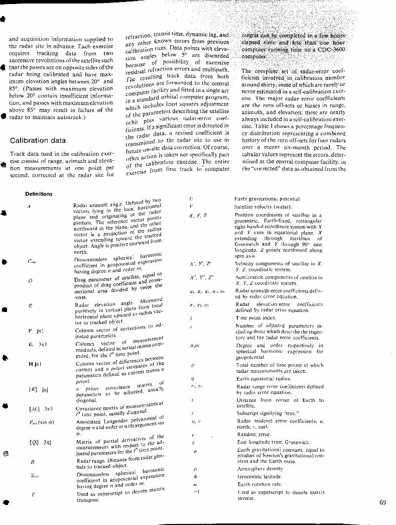
• and acquisition information supplied to the radar site in advance. Each exercise requires tracking data from two successive revolutions of the satellite such
refraction, transit time, dynamic lag, and other known errors from previous
any D"h I'b ation runs. ata POints Wit eleva-ca I r 0'
· angles below 5 are discarded tlOn 'b'I' .
.. that the passes are on opposite sides of the radar being calibrated and have maximum elevation angles between 20° and 85°. (Passes with maximum elevation below 20° contain insufficient information, and passes with maximum elevation above 85° may result in failure of the
e of POSSI I Ity of excessive becaus . . 'd al refractIOn errors and multi path.
resl u. k suIting trac data from both The re
I tions are forwarded to the central reVO u ter facility and fitted in a single arc ~om~~ndard orbital computer program, ill ~ h . eludes least squares adjustment whlc ill ., h II'
rameters descnblng t e sate Ite f the pa • radar to maintain autotrack.) o. Ius various radar-error coef-
orbit P 'f' . d d .
•
•
· . If a sigm Icant error IS etecte In
flclentsd· data a revised coefficient is
the ra ar' . . 'tted to the radar site to use In
transml . -site data correctIOn. Of course,
Calibration data
Track data used in the calibration exercise consist of range, azimuth and elevation measurements at one point per second, corrected at the radar site for
future on .. tl' on is taken not speCifically part
other ac . . alibration exercise. The entire f the c .
o . from first track to computer exercise
Definitions
A
Cnm
D
E
F jxl
G, 3xl
H jxl
[K] jxj
[M,] 3x3
Pnm (sin cP)
[Q,] 3xj
R
Snm
T
f d by tWO Radar azimuth angle. De 1m he orizOntal
I · . the loca d vectors ymg m. the ra ar .' t ng at plane and ongma I points
gimbals. The reference ve~t~~e other northward in the plane, ~r the radius vector is a prOjectIOn d the tracked vector extending towar tward from object. Angle is posluve eas north.
. I harmonic Dimensionless sphenca I expression coefficient in geopotentla having degree n and order m. I to
f t !lite equa Drag parameter 0 s~ ~ t ;nd cross-product of drag coefflcle; twice the sectional area diVided Y
mass. . Ie Measured Radar elevatIOn ang . f om local positively in vertical plane r d'us vechorizontal plane upward to ra I tor to tracked object. d-
tions to a Column vector of correc
justed parameters. measurement Column vector of I 'nus com-residuals, defined as actua ml
h ./h time pomt. puted, for tel b tween
f d "[ferences e Column vector 0 1 . tes of the'
d 'orr esuma current an a prr nt minus a parameters defined as curre
priori. . matrix of a priori covanance d usually parameters to be adJuste ,
diagonal. t at . f measuremen s
Covariance matnx o. I i'h time point, usually dlagona ., f
olynomlal 0 Associated Lengendre P ment sin degree n and order m with argu
cP. .' atives of the Matrix of parual denv the ad-
'th respect to . measurements WI ./h (me pomt. justed parameters for the 1 I .
f m radar glmRadar range. Distance ro bals to tracked object. .
· I harmOniC Dimensionless sphenca I xpression coefficient in geopotentla e having degree n and order m. .
. denote mat[lX Used as superscnpt to transpose .
u V
X, Y, Z
X', Y', Z'
X", Y", Z"
j
n,111
p
q
u, v
p
cP w
-I
output can be completed in a few hours elapsed time and less than one hour computer running time on a CDC-3600 computer.
The complete set of radar-error coefficients involved in calibration number around thirty, some of which are rarely or never estimated in a self-calibration exercise. The major radar error coefficients are the zero off-sets or biases in range, azimuth, and elevation; these are nearly always included in a self-calibration exercise. Table I shows a percentage frequency distribution representing a combined history of the zero off-sets for four radars over a recent six-month period. The tabular values represent the errors, determined at the central computer facility, in the "corrected" data as obtained from the
Earth gravitational potential.
Satellite velocity (scalar).
Position coordinates of satellite in a geocentric, Earth-fixed, rectangular right-handed coordinate system with X and Y axes in equatorial plane, X extending through meridian of Greenwich and Y through 90° east longitude. Z points northward along spin aXIs.
Velocity components of satellite in X, Y, Z, coordinate system.
Acceleration components of satellite in X. Y, Z coordinate system.
Radar azimuth-error coefficients defined by radar error equation.
Radar elevation-error coefficients defined by radar error equation.
Time point index.
Number of adjusted parameters including those which describe the trajectory and the radar error coefficients.
Degree and order respectively in spherical harmonic expression for geopotential.
Total number of time points at which radar measurements are taken.
Earth equatorial radius.
Radar range-error coefficients defined by radar error equation.
Distance from center of Earth to satellite.
Subscript signifying "true."
Radar mislevel error coefficients; u, north; v, east.
Random error.
East longitude from Greenwich.
Earth gravitational constant, equal to product of Newton's gravitational constant and the Earth mass.
Atmosphere density.
Geocentric latitude.
Earth rotation rate.
Used as superscript to denote matrix inverse.
69
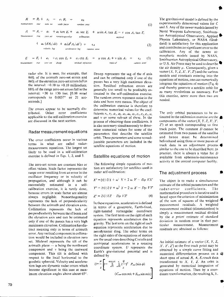
70
measurement true zero set scale factor random error (1)
A = A, + al + a2 tan E, + a3 sec E, + usinA, tan E, - v cos A, tan E, measurement true zero seI nonorthogonaliIY collimation misJevel
(2) velocity lag acceleration lag random error
measuremenl true zero sel droop residual refraction
radar site. It is seen, for example, that 94% of the azimuth zero-set errors and 86% of the elevation zero-set errors fall in the interval: -0.10 to +0.10 milliradian; 88% of the range zero-set errors fall in the interval: -30 to +30 feet. [0.10 mrad corresponds to 0.0057° or 21 arcseconds.]
The errors appear to be normally distributed. Other error coefficients applicable to the self-calibration exercise are discussed in the next section.
Radar measurement equations
The error coefficients occur in various terms in what are called radarmeasurement equations. The largest set likely to be used in a self-calibration exercise is defined in Eqs. I, 2, and 3.
The zero-set errors are constant bias or offset values. Scale factor represents the range error resulting from an error in the oscillator frequency or in velocity of propagation, and although it cah be successfully estimated in a selfcalibration exercise, it is rarely done, because errors in scale factor are almost always negligible. Nonorthogonality represents the lack of perpendicularity between the azimuth and elevation axes. Collimation represents the lack of perpendicularity between the rfbeam and the elevation axis and can be estimated only if one of the passes has a very high maximum elevation. Collimation has distinct meaning only in terms of azimuth error. Any vertical component in collimation would be included in elevation zero set. Mislevel represents the tilt of the azimuth plane - u being the northward component and v being the eastward component. This tilt is defined with respect to the local horizontal to the geodetic spheroid. Velocity and acceleration lags are dynamic radar errors which become significant in this case at maximum elevation angles above about 65°.
(3)
mislevel random error
Droop represents the sag of the rfaxis and can be estimated only if one of the passes has a very high maximum elevation. Residual refraction errors are generally too small to be profitably estimated in thB self-calibration exercise. The random errors represent noise in the data and have zero means. The object of the calibration exercise is therefore to determine numerical values for the coefficients rl, r2, aI, a2, a3, a4, as, el, e2, e3, u, and v or some sub-set of these. In the process of obtaining these coefficients, it is also necessary simultaneously to determine numerical values for some of the parameters that describe the satellite orbit. These parameters and some nonadjustable parameters are included in the satellite equations of motion.
Satellite equations of motion
The following simple equations of motion are satisfactory for satellites used in radar self-calibration:
X"=oUjoX+w2 X+2w Y- Dp vX'
Y" = 0 Uj 0 Y + w2 Y - 2 w X' - Dp VY
Z" = 0 U j 0 Z - Dp VZ' (4)
In these equations, acceleration is defined in terms of a geocentric, Earth-fixed, right-handed rectangular coordinate system. The first term on the right of each equation represents acceleration due to gravity. The last term on the right of each equation represents acceleration due to aerodynamic drag. The other terms on the right sides of the equations of motion are the usual ones describing Coriolis and centripetal accelerations in a r.otating coordinate system. U represents the Earth's gravitational potential and is defined by
J.l f n(max) n q U=-; + n~ m~ (~)" Pnm(sin</» 1 (Cnm cos rnA + Snm sin rnA~
The gravitational model is defined by the experimentally determined values for C and S. Any of the newer models issued by Naval Weapons Laboratory, Smithsonian Astrophysical Observatory, Applied. Physics Laboratory, or NASA (Goddard) is satisfactory for this application and contributes no significant error to the calibration. Any of the newer atmospheric models issued by NASA, Smithsonian Astrophysical Observatory, or U.S. Air Force may be used to describe. the air density p. Consequently, given a vector (X, Y, Z, X', Y, Z') and the various models and constants entering into the equations of motion, one can numerically integrate the equations of motion (Eq. 4) and thereby generate a satellite orbit for ~ as many revolutions as necessary. For . this exercise, never more than two are needed.
The only orbital parameters to be estimated in the calibration exercise are the" components of the vector (X, Y, Z, X', Y, Z') at an epoch corresponding to first track point. The constant D cannot be estimated from two passes of the satellite and hence must be determined beforehand using three or more passes of track data in an adjustment process. similar to the one to be described here. In practice, there is always a value for D available from ephemeris-maintenance activity at the central computer facility.
The adjustment process •
The object is to make a simultaneous estimate of the orbital parameters and the radar-error coefficients. The mathematical procedure is iterative and is based upon the criterion of minimization ..... of the sum of squares of the weighted ~ measurement residuals. A weighted measurement residual (dimensionless) is simply a measurement residual divided by the a priori estimate of standard deviation in random error in that particular measurement. Measurement residuals are obtained as follows: •
An initial estimate of a vector (X, Y, Z, X', Y', Z') at the first track point may be obtained by a simple curve fitting and numerical differentiation process on a short span of actual R, A, E,-track data transformed to X, Y, Z. An orbit is generated by numerical integration of equations of motion. Then by a coordinate transformation, the resulting X, Y,

,
•
•
•
•
•
Z time points are transformed to theoretical R, A, E measurements for the radar site. These theoretical measurements are used in place of the true but unknown measurements on the right side of the radar measurement equations (Eqs. I, 2, 3) to produce "computed" measurements. Random errors are never included in the computer measurements, and on the first iteration all other error coefficients are set to zero since they are unknown and have expectations of zero. After the first iteration there are nonzero estimates of the radar-error coefficients to use in producing computed measurements. The differences between the computed measurements and the actual measurements produce measurement residuals .
The measurement residuals from the first computation will generally be much larger than the random errors in the actual radar measurements and thus indicate that one or more of the adjusted parameters have been poorly estimated. Corrections are therefore computed and added to the original estimates of all the adjustable parameters. Corrections are computed using a basic least-squares iterative equation 1 satisfying the original minimization criterion:
F is a column vector of corrections for the adjusted parameters, including orbital parameters and radar-error coefficients. Eq. 5 is used together with the equations of motion (Eq. 4) and the radar measurement equations (Eqs. 1,2,3) like any other set of iterative equations. After a number of iterations, reductions in the sum of squares of the weighted measurement residuals become negligible, at which time the adjustment process is said to have converged, producing final estimates of all parameters. To give some idea of the accuracy in the self-calibration method, the results of a simulation exercise are presented in the next section.
Simulation exercise
Selection of the particular coefficients to be estimated in an actual calibration exercise depends upon some practical considerations that are discussed in the next section. The following treatment illustrates a possible calibration exercise.
Simulated data at one point per second for a radar on Grand Turk Island were generated assuming a Pegasus trajectory and three types of errors:
eUnadjusted parameters were represented by conservative estimates of errors in geopotential, survey, and drag;
eAdjustable parameters were represented by zero-set, mislevel, nonorthogonality, collimation, velocity lag, acceleration lag, and droop;
e Random errors (i. e., standard deviations) of 21 ft in range, 0.1 mrad in azimuth and 0.12 mrad in elevation were also introduced.
The simulated error coefficie;nts, the error coefficients estimated from the adjustment process and the differences are shown in Table II. A priori estimates for all error coefficients were zero.
Table II - Numerical results from simulation.
l:inJr Introduced Estimated Error in coe/licients value value estimate
/'] (ft) +21.0 +38.5 +17.5 {}] (mrad) + 0.070 + 0.060 - 0.010 a-:. (mrad) + 0.070 + 0.059 - 0.011 (/\ (mrad) + 0.070 + 0.079 + 0.009 a-l (s/ fad) + 0.00270 + 0.00239 - 0.00031 a, (sc,:'rad) + 0.0590 + 0.0613 + 0.0023 /I (mrad) + 0.0270 + 0.0245 - 0.0025 \' (mrad) - 0.0640 - 0.0547 + 0.0093 1'1 (mrad) + 0.070 + 0.091 + 0.021 ('c (mrad) + 0.070 + 0.053 - 0.017
Some practical considerations
In an ordinary satellite pass, the cosine E and secant E functions do not vary much, and therefore the correspond·ing droop and collimation coefficients can not be readily distinguished from the constant elevation and azimuth zero sets in the calibration exercise - hence very high maximum elevations are desirable for estimating droop and collimation. In the simulation just presented, one pass had a maximum elevation of 83°. When ideal conditions are not present, it is good practice to exclude droop and collimation from the calibration exercise and let their residual effects be absorbed in the estimates of elevation and azimuth zero sets. The lag coefficients a4 and as also cannot be estimated unless a high maximum elevation pass is available, because only in such a situation is the lag significant.
If the full set of error coefficients IS
adjusted, it will be found that even under good geometrical conditions high correlation will be observed between elevation bias and droop, and also between azimuth bias and collimation. Methods for treating nonorthogonal problems of this type have been widely discussed in the statistics literature and investigated at length at this Test Range. Refs. 2 and 3 give particularly valuable treatment. It is well known that adjustment errors caused by correlation among the adjusted parameters are associated with increased magnitude of the final value of the vector H. If the magnitude of this vector is properly restrained, the adjustments are frequently improved. A restraining influence on the size of this vector is the covariance matrix [K]. When correlation problems exist, it is frequently profitable to arrive at an approximately realistic estimate for [K] and then mUltiply [K] or a subset of[K] by a fraction (e.g., 1/3 or 1/4) before beginning the adjustment process. Such a procedure results in a statistically biased but nevertheless more accurate estimate of the adjusted parameters. In the simulation exercise just discussed, a realistic value of [K] was mUltiplied by 1/4 before proceeding with the adjustment. In a simple calibration exercise involving only zero-set estimations there is no problem with correlation· ~nd the inverse of the [K] matrix may be'defined to be a null matrix to simplify computations.
Finally, it should be pointed out that random errors in the radar data have a harmful influence on the accuracy of the adjustments. The random errors used in the simulation here represent average values at this Test Range. A 50% change in these errors is significant in terms of adjustment accuracy. Effects from random errors can sometimes be reduced by using input radar data at ten points per second instead of one point per second but only at considerable additional expense in computer time. Prefiltering tenpoint-per-second data to obtain less noisy one-point-per-second data is also a possible source of improvement that may be exploited in the future.
References
!. Sollowa\,. C. B .. "Elements of the Theory of Orbit Detcrmin~tion." JPL EP!)-255, (9 Dec 1964.)
2. Hoerl, A. E .. and Kennard. R. W., "R!dge Regression: Biased Estimation for :"JonorthogonaJ Problems," Techf1omerrics. Vol. 12. \'0. 1. (Feb 1970.)
J. Hoerl. A. E., and Kennard. R. W .. "Ridge RegreSSIon· .\pplication:. to \"onorthgona1 Problem:.." Technomelrin. Vnl. 12. :\0. I. (Feb 1970.)
71
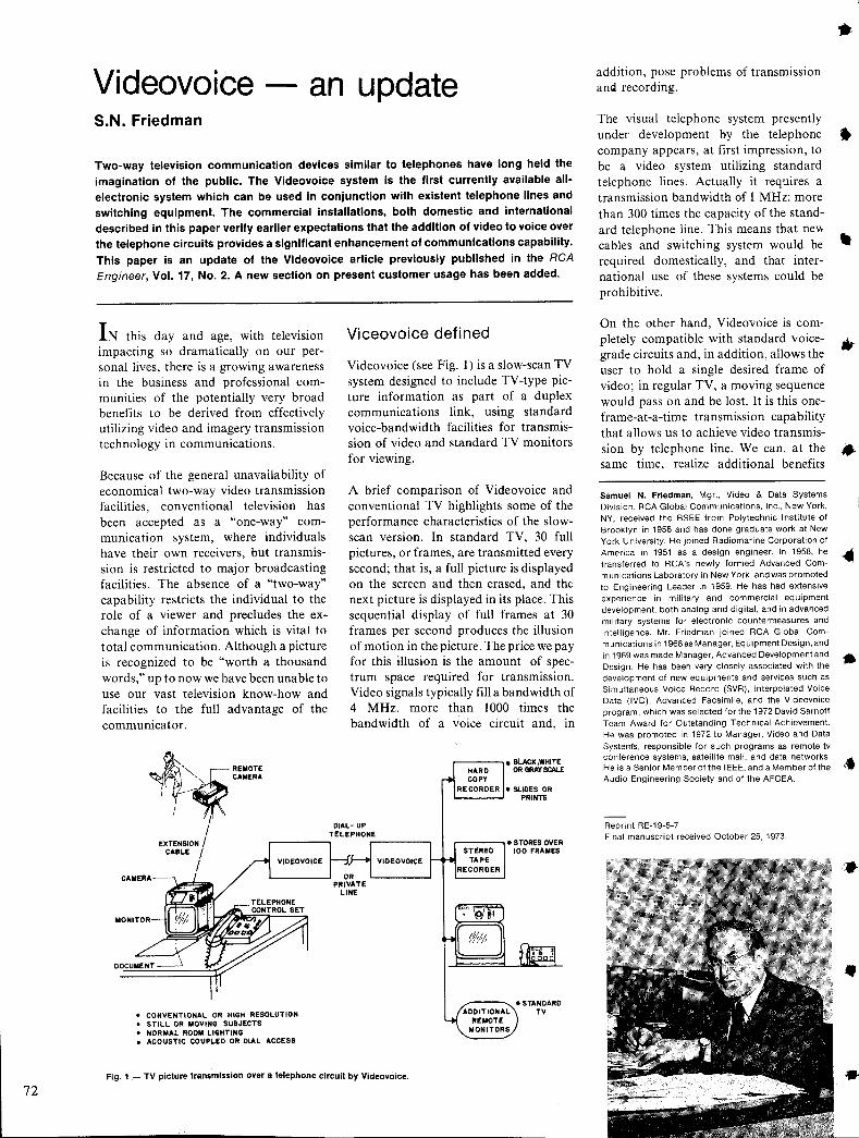
72
Videovoice an update S.N. Friedman
Two-way television communication devices similar to telephones have long held the imagination of the public. The Videovoice system is the first currently available allelectronic system which can be used in conjunction with existent telephone lines and switching equipment. The commercial installations, both domestic and international described in this paper verify earlier expectations that the addition of video to voice over the telephone circuits provides a significant enhancement of communications capability. This paper is an update of the Videovoice article previously published in the RCA Engineer, Vol. 17, No.2. A new section on present customer usage has been added.
IN this day and age, with television impacting so dramatically on our personal lives, there is a growing awareness in the business and professional communities of the potentially very broad benefits to be derived from effectively utilizing video and imagery transmission technology in communications.
Because of the general unavailability of economical two-way video transmission facilities, conventional television has been accepted as a "one-way" communication system, where individuals have their own receivers, but transmission is restricted to major broadcasting facilities. The absence of a "two-way" capability restricts the individual to the role of a viewer and precludes the exchange of information which is vital to total communication. Although a picture is recognized to be "worth a thousand words," up to now we have been unable to use our vast television know-how and facilities to the full advantage of the communicator.
"'''~ REMOTE " CAMERA
:.--~...-::; ""
I I
CAMERA
MONITOR
EXTENSION / CABLE I
/
• CONVENTIONAL OR HIGH RESOLUTION • STI LL OR MOVING SUBJECTS • NORMAL ROOM LIGHTING • ACOUSTIC COUPLED OR DIAL ACCESS
Viceovoice defined
Videovoice (see Fig. 1) is a slow-scan TV system designed to include TV -type picture information as part of a duplex communications link, using standard voice-bandwidth facilities for transmission of video and standard TV monitors for viewing.
A brief comparison of Videovoice and conventional TV highlights some of the performance characteristics of the slowscan version. In standard TV, 30 full pictures, or frames, are transmitted every second; that is, a full picture is displayed on the screen and then erased, and the next picture is displayed in its place. This sequential display of full frames at 30 frames per second produces the illusion of motion in the picture. The price we pay for this illusion is the amount of spectrum space required for transmission. Video signals typically fill a bandwidth of 4 MHz, more than 1000 times the bandwidth of a voice circuit and, in
.--------, • STORES OVER 100 FRAMES
Fig. 1 - TV picture transmission over a telephone circuit by Videovoice.
addition, pose problems of transmission and recording.
The visual telephone system presently under development by the telephone company appears, at first impression, to be a video system utilizing standard telephone lines. Actually it requires a transmission bandwidth of 1 MHz: more than 300 times the capacity of the standard telephone line. This means that new cables and switching system would be required domestically, and that international use of these systems could be prohibitive.
On the other hand, Videovoice is completely compatible with standard voicegrade circuits and, in addition, allows the user to hold a single desired frame of video; in regular TV, a moving sequence would pass on and be lost. It is this oneframe-at-a-time transmission capability that allows us to achieve video transmission by telephone line. We can, at the same time, realize additional benefits
Samuel N. Friedman, Mgr., Video & Data Systems Division, RCA Global Communications, Inc., New York, NY, received the BSEE from Polytechnic Institute ilf Brooklyn in 1956 and has done graduate work at New York University. He joined Radiomarine Corporation of America in 1951 as a design engineer. In 1958, he transferred to RCA's newly formed Advanced Communications Laboratory in New York. and was promoted to Engineering Leader in 1959. He has had extensive experience in military and commercial equipment development, both analog and digital, and in advanced military systems for electronic countermeasures and intelligence. Mr. Friedman joined RCA Global Communications in 1968as Manager, Equipment Design, and in 1969 was made Manager, Advanced Developmentand Design. He has been very closely associated with the development of new equipments and services such as Simultaneous Voice Record (SVR), Interpolated Voice Data (IVD), Advanced Facsimile, and the Videovoice program, which was selected for the 1972 David Sarnoff Team Award for Outstanding Technical Achievement. He was promoted in 1972 to Manager, Video and Data Systems, responsible for such programs as remote tv conference systems, satellite mail, and data networks. He is a Senior Member of the IEEE, and a Member of the Audio Engineering Society and of the AFCEA.
Reprint RE-19-5-7 Final manuscript received October 25, 1973.
•
•
•
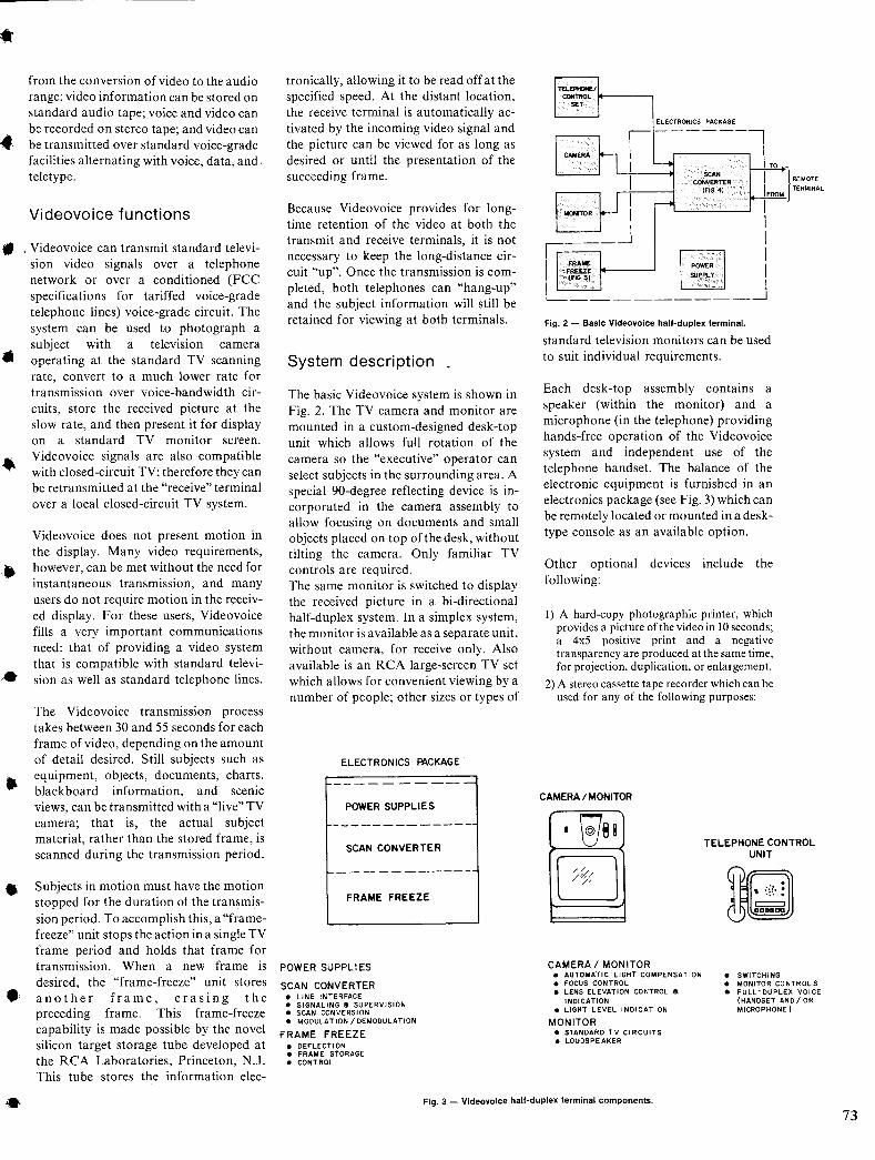
• from the conversion of video to the audio range: video information can be stored on standard audio tape; voice and video can be recorded on stereo tape; and video can be transmitted over standard voice-grade facilities alternating with voice, data, and, teletype.
Videovoice functions
• . Videovoice can transmit standard television video signals over a telephone network or over a conditioned (FCC specifications for tariffed voice-grade telephone lines) voice-grade circuit. The system can be used to photograph a subject with a television camera operating at the standard TV scanning rate, convert to a much lower rate for transmission over voice-bandwidth circuits, store the received picture at the slow rate, and then present it for display on a standard TV monitor screen. Videovoice signals are also compatible with closed-circuit TV; therefore they can be retransmitted at the "receive" terminal over a local closed-circuit TV system.
•
•
..
Videovoice does not present motion in the display, Many video requirements, however, can be met without the need for instantaneous transmission, and many users do not require motion in the received display. For these users, Videovoice fills a very important communications need: that of providing a video system that is compatible with standard television as well as standard telephone lines.
The Videovoice transmission process takes between 30 and 55 seconds for each frame of video, depending on the amount of detail desired. Still subjects such as equipment, objects, documents, charts, blackboard information, and scenic views, can be transmitted with a "live" TV camera; that is, the actual subject material, rather than the stored frame, is scanned during the transmission period.
Subjects in motion must have the motion stopped for the duration of the transmission period. To accomplish this, a "framefreeze" unit stops the action in a single TV frame period and holds that frame for transmission. When a new frame is desired, the "frame-freeze" unit stores another frame, erasing the preceding frame. This frame-freeze capability is made possible by the novel silicon target storage tube developed at the RCA Laboratories, Princeton, N.J. This tube stores the information elec-
tronically, allowing it to be read off atthe specified speed. At the distant location, the receive terminal is automatically activated by the incoming video signal and the picture can be viewed for as long as desired or until the presentation of the succeeding frame.
Because Videovoice provides for longtime retention of the video at both the transmit and receive terminals, it is not necessary to keep the long-distance circuit "up". Once the transmission is completed, both telephones can "hang-up" and the subject information will still be retained for viewing at both terminals.
System description
The basic Videovoice system is shown in Fig. 2. The TV camera and monitor are mounted in a custom-designed desk-top unit which allows full rotation of the camera so the "executive" operator can select subjects in the surrounding area. A special 90-degree reflecting device is incorporated in the camera assembly to allow focusing on documents and small objects placed on top of the desk, without tilting the camera. Only familiar TV controls are required. The same monitor is switched to display the received picture in a bi-directional half-duplex system. In a simplex system, the monitor is available as a separate unit, without camera, for receive only, Also available is an RCA large-screen TV set which allows for convenient viewing by a number of people; other sizes or types of
ELECTRONICS PACKAGE'
----------POWER SUPPLIE S
SCAN CONVERTER
f--- - -- ------
FRAME FREEZE
POWER SUPPLIES
SCAN CONVERTER • LINE INTERFACE • SIGNALING a SUPERVISION • SCAN CONVERSION • MODULAT ION / DEMODULATION
FRAME FREEZE • DEFLECTlON • FRAME STORAGE • CONTROL
ELECTRONICS PACKAGE
Fig. 2 - Basic Videovoice half-duplex terminal.
standard television monitors can be used to suit individual requirements.
Each desk-top assembly contains a speaker (within the monitor) and a microphone (in the telephone) providing hands-free operation of the Videovoice system and independent use of the telephone handset. The balance of the electronic equipment is furnished in an electronics package (see Fig. 3) which can be remotely located or mounted in a desktype console as an available option.
Other optional devices include the following:
I) A hard-copy photographic printer, which provides a picture of the video in 10 seconds; a 4x5 positive print and a negative transparency are produced at the same time, for projection, duplication, or enlargement.
2) A stereo cassette tape recorder which can be used for any of the following purposes:
CAMERA I MONITOR
• ~88
~ CAMERA I MONITOR
• AUTOMATIC LIGHT COMPENSATION • FOCUS CONTROL • LENS ELEVATION CONTROL 8
INDICATION • LIGHT LEVEL INDICATION
MONITOR • STANDARD TV CIRCUITS • LOUDSPEAKER
TELEPHONE CONTROL UNIT
= DODaaa
• SWITCHING • MONITOR CONTROLS • FULL-DUPLEX VOICE
(HANDSET ANDI OR MICROPHONE)
Fig. 3 - Videovoice half-duplex terminal components.
73
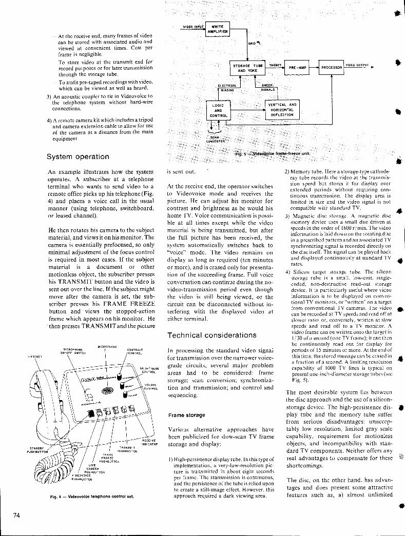
74
- At the receive end, many frames of video can be stored with associated audio and viewed at convenient times. Cost per frame is negligible.
- To store video at the transmit end for record purposes or for later transmission through the storage tube.
- To audit pre-taped recordings with video, which can be viewed as well as heard.
3) An acoustic coupler to tie in Videovoice to the telephone system without hard-wire connections.
4) A remote camera kit which includes a tripod and camera extension cable to allow for use of the camera at a distance from the main equipment.
System operation
An example illustrates how the system operates. A subscriber at a telephone terminal who wants to send video to a remote office picks up his telephone (Fig. 4) and places a voice call in the usual manner (using telephone, switchboard, or leased channel).
He then rotates his camera to the subject material, and views it on his monitor. The camera is essentially prefocused, so only minimal adjustment of the focus control is required in most cases. If the subject material IS a document or other motionless object, the subscriber presses his TRANSMIT button and the video is sent out over the line. If the subject might move after the camera is set, the subscriber presses his FRAME FREEZE button and views the stopped-action frame which appears on his monitor. He then presses TRANSMIT and the picture
MICROPHONE
Fig. 4 - Videovolce telephone control set.
VIOEO INPUT
GRID '"I
VIDEO OUTPUT
HORIZONTAL DEFLECTION
I.........,-J SCAN
CONvERTER:
Fig. 5 - Vldeovolce frame-freeze unil.
is sent out.
At the receive end, the operator switches to Videovoice mode and receives the picture. He can adjust his monitor for contrast and brightness as he would his home TV. Voice communication is possible at all times except while the video material is being transmitted, but after the full picture has been received, the system automatically switches back to "voice" mode. The video remains on display as long as required (ten minutes or more), and is erased only for presentation of the succeeding frame. Full voice conversation can continue during the novideo-transmission period even though the video is still being viewed, or the circuit can be disconnected without interfering with the displayed video at either terminal.
Technical considerations
In processing the' standard video signal for transmission over the narrower voicegrade circuits, several major problem areas had to be considered: frame storage; scan conversion; synchronization and transmission; and control and sequencing.
Frame storage
Various alternative approaches have been publicized for slow-scan TV frame storage and display:
I) High-persistence display tube. In this type of implementation, a very-low-resolution picture is transmitted in about eight seconds per frame. The transmission is continuous, and the persistence of the tube is relied upon to create a still-image effect. However, this approach required a dark viewing area.
2) Memory tube. Here a storage-type cathoderay tube records the video at the transmission speed but stores it for display over extended periods without requiring continuous transmission. The display area is limited in size and the video signal is not compatible with standard TV.
3) Magnetic disc storage. A magnetic disc memory device uses a small disc driven at speeds in the order of 1800 r I min. The video information is laid down on the rotating disc in a prescribed pattern and an associated TV synchronizing signal is recorded directly on the disc itself. The signal can be played back and displayed continuously at standard TV rates.
4) Silicon target storage tube. The silicon storage tube is a small, low-cost, singleended, non-destructive read-out storage device. It is particularly useful where video information is to be displayed on conventional TV monitors, or "written" on a target from conventional TV cameras. The video can be recorded at TV speeds and read off at slower rates or, conversely, written at slow speeds and read off to a TV monitor. A video frame can be written onto the target in 1j30 ofa second (one TV frame); itcan then be continuo.usly read out for display for periods of 15 minutes or more. At the end of this time, the stored message can be erased in a fraction of a second. A limiting resolution capability of 1000 TV lines is typical on present one-inch-diameter storage tubes (see Fig. 5).
The most desirable system lies between the disc approach and the use of a siliconstorage device. The high-persistence display tube and the memory tube suffer from serious disadvantages: unacceptably low resolution, limited gray scale capability, requirement for motionless objects, and incompatibility with standard TV components. Neither offers any real advantages to compensate for these shortcomings.
The disc, on the other hand, has advantages and does present some attractive features such as, a) almost unlimited
.'
•
•
•
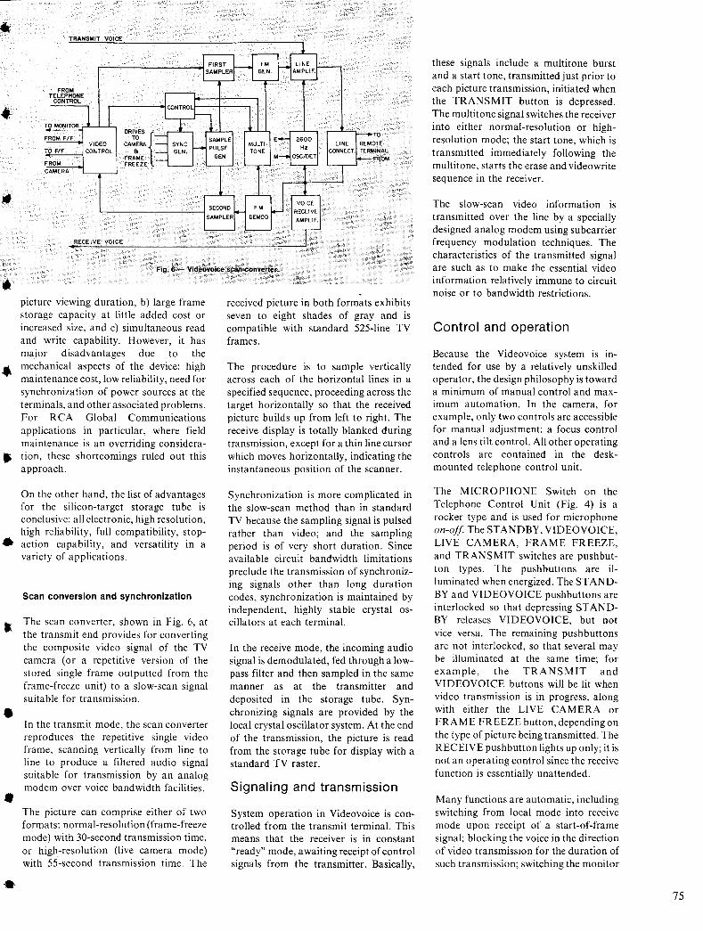
FROM TELEPHONE
CONTROL
TO MONITOR
FROM FtF
TO Flf
fROM CAMERA
SAMPLER AMPUF,
RECEIVE VOICE
Fig. 6 - Videovoice scan converter.
picture viewing duration, b) large frame storage capacity at little added cost or increased size, and c) simultaneous read and write capability. However, it has major disadvantages due to the
.. mechanical aspects of the device: high maintenance cost, low reliability, need for synchronization of power sources at the terminals, and other associated problems. For RCA Global Communications applications in particular, where field maintenance is an overriding considera-
• tion, these shortcomings ruled out this approach.
•
•
•
•
On the other hand, the list of advantages for the silicon-target storage tube is conclusive: all electronic, high resolution, high reliability, full compatibility, stopaction capability, and versatility in a variety of applications.
Scan conversion and synchronization
The scan converter, shown in Fig. 6, at the transmit end provides for converting the composite video signal of the TV camera (or a repetitive version of the stored single frame outputted from the frame-freeze unit) to a slow-scan signal suitable for transmission.
In the transmit mode, the scan converter reproduces the repetitive single video frame, scanning vertically from line to line to produce a filtered audio signal suitable for transmission by an analog modem over voice bandwidth facilities.
The picture can comprise either of two formats: normal-resolution (frame-freeze mode) with 30-second transmission time, or high-resolution (live camera mode) with 55-second transmission time. The
received picture in both formats exhibits seven to eight shades of gray and is compatible with standard 525-line TV frames.
The procedure is to sample vertically across each of the horizontal lines in a specified sequence, proceeding across the target horizontally so that the received picture builds up from left to right. The receive display is totally blanked during transmission, except for a thin line cursor which moves horizontally, indicating the instantaneous position of the scanner.
Synchronization is more complicated in the slow-scan method than in standard TV because the sampling signal is pulsed rather than video; and the sampling period is of very short duration. Since available circuit bandwidth limitations preclude the transmission of synchronizing signals other than long duration codes, synchronization is maintained by independent, highly stable crystal oscillators at each terminal.
In the receive mode, the incoming audio signal is demodulated, fed through a lowpass filter and then sampled in the same manner as at the transmitter and deposited in the storage tube. Synchronizing signals are provided by the local crystal oscillator system. At the end of the transmission, the picture is read from the storage tube for display with a standard TV raster.
Signaling and transmission
System operation in Videovoice is controlled from the transmit terminal. This means that the receiver is in constant "ready" mode, awaiting receipt of control signals from the transmitter. Basically,
these signals include a multitone burst and a start tone, transmitted just prior to each picture transmission, initiated when the TRANSMIT button is depressed. The multitone signal switches the receiver into either normal-resolution or highresolution mode; the start tone, which is transmitted immediately following the multitone, starts the erase and videowrite sequence in the receiver.
The slow-scan video information is transmitted over the line by a specially designed analog modem using subcarrier frequency modulation techniques. The characteristics of the transmitted signal are such as to make the essential video information relatively immune to circuit noise or to bandwidth restrictions.
Control and operation
Because the Videovoice system is intended for use by a relatively unskilled operator, the design philosophy is toward a minimum of manual control and maximum automation. In the camera, for example, only two controls are accessible for manual adjustment: a focus control and a lens tilt control. All other operating controls are contained in the deskmounted telephone control unit.
The MICROPHONE Switch on the Telephone Control Unit (Fig. 4) is a rocker type and is used for microphone on-off. The STANDBY, VIDEOVOICE, LIVE CAMERA, FRAME FREEZE, and TRANSMIT switches are pushbutton types. The pushbuttons are illuminated when energized. The ST ANDBY and VIDEOVOICE pushbuttons are interlocked so that depressing ST ANDBY releases VIDEOVOICE, but not vice versa. The remaining push buttons are not interlocked, so that several may be illuminated at the same time; for example, the TRANSMIT and VIDEOVOICE buttons will be lit when video transmission is in progress, along with either the LIVE CAMERA or FRA ME FREEZE button, depending on the type of picture being transmitted. The RECEIVE pushbutton lights up only; it is not an operating control since the receive function is essentially unattended.
Many functions are automatic, including switching from local mode into receive mode upon receipt of a start-of-frame signal; blocking the voice in the direction of video transmission for the duration of such transmission; switching the monitor
75
76
between the camera and the frame freeze unit; switching between the telephone handset (if used) and the loudspeaker system; switching from standby power on the video equipments to full power when the VIDEOVOICE switch is actuated; camera enlargement and reduction of the subject matter; and automatic light compensation in the camera to adjust for varying scene brightness.
During the receive cycle, all functions are automated. When a terminal initiates a video transmission, it transmits a code which contains synchronization and picture resolution information. When detected at the other terminal, the code starts the receive cycle, which consists of receiver-setup in proper resolution mode, storage-tube "erase", "write" and "read" cycling, and "start-of-frame" synchronization.
Commercial applications
Videovoice is a particularly significant development; it opens the way for visual communications by telephone, a capability which was heretofore precluded by both technology and economics. The long-range applications are almost unlimited. For the near term, we can mention the following:
I) Pictures of parts and assemblies for manufacturing purposes, maintenance and repair instruction, and spare parts catalog.
2) Advertising and sales promotion.
3) Materials for the identification of people; signatures.
4) Drawings, charts, maps, and schematics for conferences and discussions.
5) Educational and training material to support an illustrated lecture, a blackboard-bywire demonstration, or a textbook-on-audio tape.
6) Purchasing and inventory control documents and supporting photographs.
7) Telephone circuit interface to closed circuit TV systems.
8) Cardiograms, x-rays, and other medical graphic data.
9) Airlines arrival-departure information.
10) Brokerage display boards.
II) Banking, administration, and accounting material.
12) Videovoice can be used to input video data into a computer for data processing and to graphically display computer outputs.
Present customer usage
Since the original article was written, a substantial number of Videovoice terminals have been installed on customer premises and are being put to practical use, operated completely by their people. It is interesting to review the previous assessment of "commercial possibilities" in light of actual customer applications.
• One large company has installed Videovoice terminals in a number of locations distributed around the country; the terminals are used solely for remote conferences. Tying in the video capability with telephone conferencing directly into conference rooms has, in the opinion ofthis company, resulted in significant savings in travel expense as well in a sll.bstantial improvement in company-wide communications.
The Videovoice conference facility is used by all departments including personnel, finance, technical, etc., besides executive conferencing. Presentation material for the conference is prepared for use via the Videovoice format; and the demand for the facility is so great that a strict reservation schedule is maintained.
• A large electronics company uses its Videovoice terminal system for remote field quality control; that is, they have the terminal installed in a vendor's plant, and it is used to transmit close-up details of fabricated items, like a printed circuit board or mask, back to the central quality control facility for inspection and consequent acceptance or rejection. Where extra fine detail is required, the Videovoice camera is focused through a microscope with 40X magnification.
• One medically oriented installation provides for transmission between the doctor's office and the hospital for close-up examination and remote evaluation of x-rays, medical graphic data, and microscope slides viewed by the Video voice camera through the microscope eyepiece.
• Another medical 'use is from a conference room on the obstretrics floor of a hospital to a distant university medical school lecture hall, serving a simultaneous education function.
• In the automotive industry, it is used for auto parts design and end-product evaluaton between offices and the main plant.
• Major oil company usage is for ship-toshore video from oil freighters at sea via satellite. The nature of the information includes seismic and oceanographic data, offshore oil installations, and equipment information, etc.
• A major cable TV company uses Videovoice terminals in their own offices for executive conferences in addition to offering it as an added service to subscribers on their private voice grade circuits. They feel this provides them with a competitive advantage over the regular telephone companies who do not offer such service.
• A major construction planning and civil
engineering firm finds Videovoice very helpful to review layouts of plumbing, heating and air-conditioning ducts and for remote discussion of structural details as described in their architectural and mechanical drawings. ..
• A leading cosmetic firm makes use of Videovoice for transmission of advertising material and packaging design artwork for discussion and correction.
• In industrial and business use, technical conferencing and review of graphic informa- til. tion is common practice with many of our subscribers, including numerous RCA locations.
• Executive conferencing by Videovoice is also very popular and top executives in some of the major companies have expressed their satisfaction with the system
• Government and defense agencies currently .. cover a broad range of specialized and sophisticated applications, although details cannot be generally released.
Among the more exciting applications, we can include the following:
• Video conferencing from shore points in the United States to the ship Hope in various ports-of-call in South America, mainly, for exchange of medical information.
• In conjunction with Apollo 17, Videovoice was used to relay continually updated track-ing information, generated from earth :III
locations, of the lunar rover on the moon .. surface, and also to monitor the depolyment of recovery fleet ships in preparation for splashdown.
• Videovoice will be used for continuously updating antenna positions from video on the orbiting Skylab unit and collecting other information.
• International acceptance has also been very gratifying. The People's RepUblic of China was quick to recognize the benefits for conferencing and for long-distance telecommunications with emphasis on transmission of Chinese characters. Spain was next to join the Videovoice international user list. which now includes Sweden, as well. We further expect to receive orders shortly from at least five other European countries and others in South America and the Far East.
The interest in all of these countries is at the very highest levels of government and industry, which makes the outlook so • much more promising.
In general then, all of the projected uses for Videovoice have materialized, and in addition, new ones are being discovered as the usage of the terminals expands. And, in keeping with our earlier expec- • tations, it is being recognized that, where communications are required, the use of Videovoice can enhance efficiency and intelligibility, and at the same time, contribute significantly to circuit utilization.
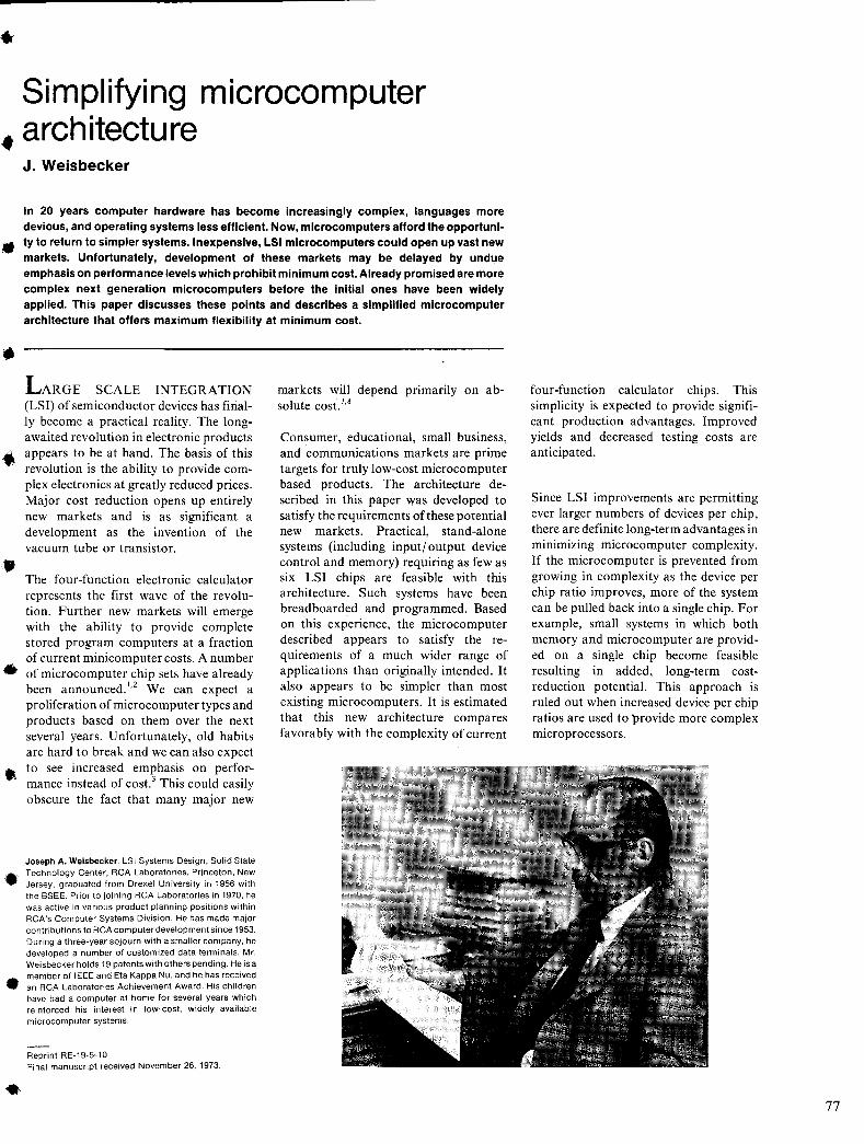
Simplifying microcomputer • architecture
J. Weisbecker
In 20 years computer hardware has become increasingly complex, languages more devious, and operating systems less efficient. Now, microcomputers afford the opportuni-
• ty to return to simpler systems. Inexpensive, LSI microcomputers could open up vast new markets. Unfortunately, development of these markets may be delayed by undue emphasis on performance levels which prohibit minimum cost. Already promised are more complex next generation microcomputers before the initial ones have been widely applied. This paper discusses these points and describes a simplified microcomputer architecture that offers maximum flexibility at minimum cost.
SCALE INTEGRATION (LSI) of semiconductor devices has finally become a practical reality. The longawaited revolution in electronic products
• appears to be at hand. The basis of this revolution is the ability to provide complex electronics at greatly reduced prices. Major cost reduction opens up entirely new markets and is as significant a development as the invention of the vacuum tube or transistor.
•
The four-function electronic calculator represents the first wave of the revolution. Further new markets will emerge with the ability to provide complete stored program computers at a fraction of current minicomputer costs. A number of microcomputer chip sets have already been announced. 1
,2 We can expect a proliferation of microcomputer types and products based on them over the next several years. Unfortunately, old habits are hard to break and we can also expect
•. to see increasedf
em~hasis on performance instead 0 cost. This could easily obscure the fact that many major new
Joseph A. Weisbecker, LSI Systems Design, Solid State
• Technology Center, RCA Laboratories, Princeton, New Jersey, graduated from Drexel University in 1956 with the BSEE. Prior to joining RCA Laboratories in 1970, he was active in various product planning positions within RCA's Computer Systems Division. He has made major contributions to RCA computer development since 1953. During a three-year sojourn with a smaller company, he developed a number of customized data terminals. Mr. Weisbecker holds 19 patents with others pending. He is a member of IEEE and Eta Kappa Nu, and he has received
• an RCA Laboratories Achievement Award. His children have had a computer at home for several years which reinforced his interest in low-cost, widely available microcomputer systems.
Reprint RE·19-5-10 Final manuscript received November 26, 1973.
•
markets will depend primarily on absolute cost. 7.8
Consumer, educational, small business, and communications markets are prime targets for truly low-cost microcomputer based products. The architecture described in this paper was developed to satisfy the requirements of these potential new markets. Practical, stand-alone systems (including input/ output device control and memory) requiring as few as six LSI chips are feasible with this architecture. Such systems have been breadboarded and programmed. Based on this experience, the microcomputer described appears to satisfy the requirements of a much wider range of applications than originally intended. It also appears to be simpler than most existing microcomputers. It is estimated that this new architecture compares favorably with the complexity of current
four-function calculator chips. This simplicity is expected to provide significant production advantages. Improved yields and decreased testing costs are anticipated.
Since LSI improvements are permitting ever larger numbers of devices per chip, there are definite long-term advantages in minimizing microcomputer complexity. If the microcomputer is prevented from growing in complexity as the device per chip ratio improves, more of the system can be pulled back into a single chip. For example, small systems in which both memory and microcomputer are provided on a single chip become feasible resulting in added, long-term costreduction potential. This approach is ruled out when increased device per chip ratios are used to provide more complex microprocessors.
77
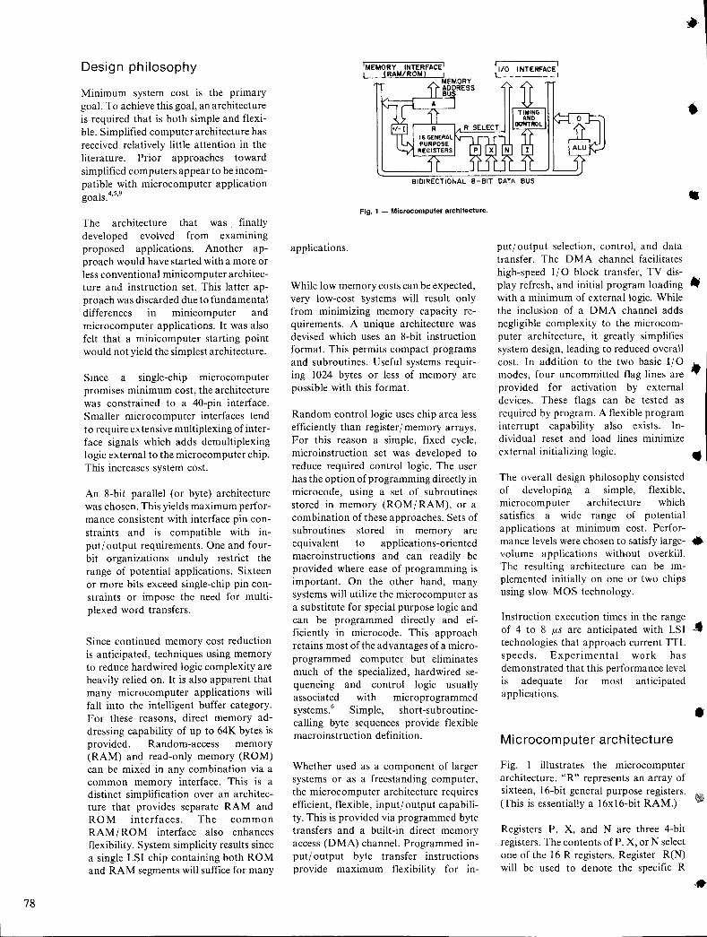
78
Design philosophy
Minimum system cost is the primary goal. To achieve this goal, an architecture is required that is both simple and flexible. Simplified computer architecture has received relatively little attention in the literature. Prior approaches toward simplified computers appear to be incompatible with microcomputer application goals. 4
•5
•9
The architecture that was finally developed evolved from examining proposed applications. Another approach would have started with a more or less conventional minicomputer architecture and instruction set. This latter appro\ich was discarded due to fundamental differences in minIcomputer and microcomputer applications. It was also felt that a minicomputer starting point would not yield the simplest architecture.
Since a single-chip microcomputer promises minimum cost, the architecture was constrained to a 40-pin interface. Smaller microcomputer interfaces tend to require extensive mUltiplexing of interface signals which adds demultiplexing logic external to the microcomputer chip. This increases system cost.
An 8-bit parallel (or byte) architecture was chosen. This yields maximum performance consistent with interface pin constraints and is compatible with input/ output requirements. One and fourbit organizations unduly restrict the range of potential applications. Sixteen or more bits exceed single-chip pin constraints or impose the need for multiplexed word transfers.
Since continued memory cost reduction is anticipated, techniques using memory to reduce hardwired logic complexity are heavily relied on. It is also apparent that many microcomputer applications will fall into the intelligent buffer category. For these reasons, direct memory addressing capability of up to 64K bytes is provided. Random-access memory (RAM) and read-only memory (ROM) can be mixed in any combination via a common memory interface. This is a distinct simplification over an architecture that provides separate RAM and ROM interfaces. The common RAM / RO M interface also enhances flexibility. System simplicity results since a single LSI chip containing both ROM and RAM segments will suffice for many
'MEMORY INTERFACE I I (RAM/ROt.O
11/0 INTERFACE I t I
.. BIDIRECTIONAL B-BIT DATA BUS
Fig. 1 - Microcomputer archilecture.
applications.
While low memory costs can be expected, very low-cost systems will result only from minimizing memory capacity requirements. A unique architecture was devised which uses an 8-bit instruction format. This permits compact programs and subroutines. Useful systems requiring 1024 bytes or less of memory are possible with this format.
Random control logic uses chip area less efficiently than register/memory arrays. For this reason a simple, fixed cycle, microinstruction set was developed to reduce required control logic. The user has the option of programming directly in microcode, using a set of subroutines stored in memory (ROM/ RAM), or a combination of these approaches. Sets of subroutines stored III memory are equivalent to applications-oriented macroinstructions and can readily be provided where ease of programming is important. On the other hand, many systems will utilize the microcomputer as a substitute for special purpose logic and can be programmed directly and efficiently in microcode. This approach retains most of the advantages of a microprogrammed computer but eliminates much of the specialized, hardwired sequencing and control logic usually associated with microprogrammed systems.6 Simple, short-subroutine-calling byte sequences provide flexible macroinstruction definition.
Whether used as a component of larger systems or as a freestanding computer, the microcomputer architecture requires efficient, flexible, input/ output capability. This is provided via programmed byte transfers and a built-in direct memory access (DMA) channel. Programmed input/ output byte transfer instructions provide maximum flexibility for in-
• put/ output selection, control, and data transfer. The DMA channel facilitates high-speed I/O block transfer, TV display refresh, and initial program loading • with a minimum of external logic. While the inclusion of a DMA channel adds negligible complexity to the microcomputer architecture, it greatly simplifies system design, leading to reduced overall cost. In addition to the two basic I/O • modes, four uncommitted flag lines are provided for activation by external devices. These flags can be tested as required by program. A flexible program interrupt capability also exists. Individual reset and load lines minimize external initializing logic. ..
The overall design philosophy consisted of developing a simple, flexible, microcomputer architecture which satisfies a wide range of potential applications at minimum cost. Performance levels were chosen to satisfy large- • volume applications without overkill. The resulting architecture can be implemented initially on one or two chips using slow MOS technology.
Instruction execution times in the range of 4 to 8 J.1S are anticipated with LSI .. technologies that approach current TTL speeds. Experimental work has demonstrated that this performance level is adequate for most anticipated applications.
Microcomputer architecture
Fig. I illustrates the microcomputer architecture. "R" represents an array of sixteen, 16-bit general purpose registers. (This is essentially a 16xl6-bit RAM.)
Registers P, X, and N are three 4-bit registers. The contents of P, X, or N select one of the 16 R registers. Register R(N) will be used to denote the specific R
•
..
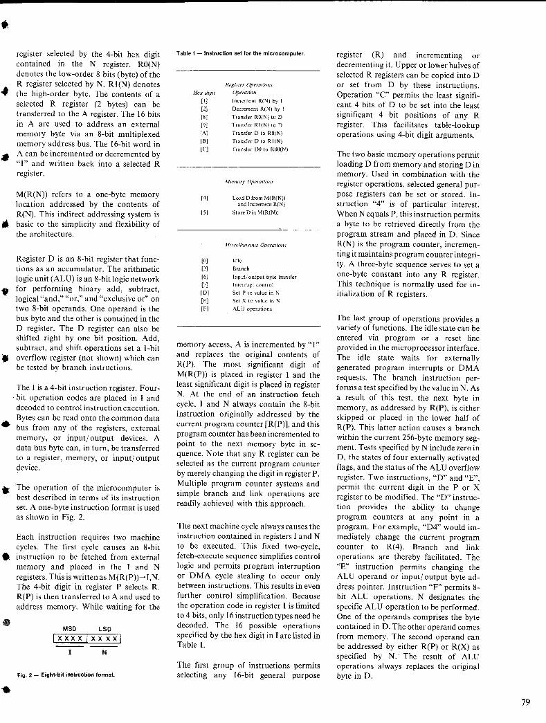
• register selected by the 4-bit hex digit contained in the N register. RO(N) denotes the low-order 8 bits (byte) of the
• R register selected by N. RI(N) denotes 'lIP the high-order byte. The contents of a
selected R register (2 bytes) can be transferred to the A register. The 16 bits in A are used to address an external memory byte via an 8-bit multiplexed memory address bus. The 16-bit word in
• A can be incremented or decremented by "I" and written back into a selected R register.
M(R(N)) refers to a one-byte memory location addressed by the contents of R(N). This indirect addressing system is *' basic to the simplicity and flexibility of the architecture.
Register D is an 8-bit register that functions as an accumulator. The arithmetic logic unit (ALU) is an 8-bit logic network
• for performing binary add, subtract, logical "and," "or," and "exclusive or" on two 8-bit operands. One operand is the bus byte and the other is contained in the D register. The D register can also be shifted right by one bit position. Add, subtract, and shift operations set a I-bit
• overflow register (not shown) which can be tested by branch instructions.
•
The I is a 4-bit instruction register. Four-. bit operation codes are placed in I and
decoded to control instruction execution. Bytes can be read onto the common data bus from any of the registers, external memory, or input/ output devices. A data bus byte can, in turn, be transferred to a register, memory, or input/ output device.
• The operation of the microcomputer is best described in terms of its instruction set. A one-byte instruction format is used as shown in Fig. 2.
Each instruction requires two machine cycles. The first cycle causes an 8-bit
• instruction to be fetched from external memory and placed in the I and N registers. This is written as M(R(P))~ I,N. The 4-bit digit in register P selects R. R(P) is then transferred to A and used to address memory. While waiting for the
MSD LSD xxxx I XX xxi
I N
Fig. 2 - Eight·bit instruction format.
Table I - Instruction set for the microcomputer.
Hex digit
[I]
[2]
[8]
[9]
[A]
[B]
[C]
Register Operations
Operation
Increment R(N) by I
Decrement R(N) by I
Transfer ROO') to D
Transfer RI(N) to D
Transfer D to RO(N)
Transfer D to RI(N)
Transfer DO to ROO(N)
Memory Operations
[4] Load D from M(R(N)) and Increment R(N)
[5] Store D in M(R(N))
l1iscellaneuus OperaTions
[0] Idle
[3] Branch
[6] Input/ output byte transfer
[7] I nterrupt control
[D] Set P to value in N
[E] Set X to value in N
[F] ALU operations
memory access, A is incremented by "I" and replaces the original contents of R(P). The most significant digit of M(R(P)) is placed in register I and the least significant digit is placed in register N. At the end of an instruction fetch cycle, I and N always contain the 8-bit instruction originally addressed by the current program counter [R(P)], and this program counter has been incremented to point to the next memory byte in sequence. Note that any R register can be selected as the current program counter by merely changing the digit in register P. Multiple program counter systems and simple branch and link operations are readily achieved with this approach.
The next machine cycle always causes the instruction contained in registers I and N to be executed. This fixed two-cycle, fetch-execute sequence simplifies control logic and permits program interruption or DMA cycle stealing to occur only between instructions. This results in even further control simplification. Because the operation code in register I is limited to 4 bits, only 16 instruction types need be decoded. The 16 possible operations specified by the hex digit in I are listed in Table I.
The first group of instructions permits selecting any 16-bit general purpose
register (R) and incrementing or decrementing it. Upper or lower halves of selected R registers can be copied into D or set from D by these instructions. Operation "c" permits the least significant 4 bits of D to be set into the least significant 4 bit positions of any R register. This facilitates table-lookup operations using 4-bit digit arguments.
The two basic memory operations permit loading D from memory and storing D in memory. Used in combination with the register operations, selected general purpose registers can be set or stored. Instruction "4" is of particular interest. When N equals P, this instruction permits a byte to be retrieved directly from the program stream and placed in D. Since R(N) is the program counter, incrementing it maintains program counter integrity. A three-byte sequence serves to set a one-byte constant into any R register. This technique is normally used for initialization of R registers.
The last group of operations provides a variety of functions. The idle state can be entered via program or a reset line provided in the microprocessor interface. The idle state waits for externally generated program interrupts or DMA requests. The branch instruction performs a test specified by the value in N. As a result of this test, the next byte in memory, as addressed by R(P), is either skipped or placed in the lower half of R(P). This latter action causes a branch within the current 256-byte memory segment. Tests specified by N include zero in D, the states of four externally activated flags, and the status of the ALU overflow register. Two instructions, "D" and "E", permit the current digit in the P or X register to be modified. The "D" instruction provides the ability to change program counters at any point in a program. For example, "D4" would immediately change the current program counter to R(4). Branch and link operations are thereby facilitated. The "E" instruction permits changing the ALU operand or input/ output byte address pointer. Instruction "F" permits 8-bit ALU operations. N designates tht: specific ALU operation to be performed. One of the operands comprises the byte contained in D. The other operand comes from memory. The second operand can be addressed by either R(P) or R(X) as specified by N.· The result of ALU operations always replaces the original byte in D.
79
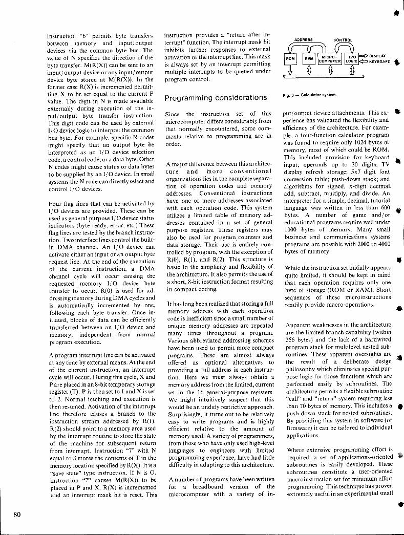
80
Instruction "6" permits byte transfers between memory and inputloutput devices via the common byte bus. The value of N specifies the direction of the byte transfer. M(R(X» can be sent to an inputloutput device or any inputl output device byte stored at M(R(X». In the former case R(X) is incremented permitting X to be set equal to the current P value. The digit in N is made available externally during execution of the inputloutput byte transfer instruction. This digit code can be used by external 110 device logic to interpret the common bus byte. For example, specific N codes might specify that an output byte be interpreted as an 110 device selection code, a control code, or a data byte. Other N codes might cause status or data bytes to be supplied by an 110 device. In small systems the N code can directly select and control 110 devices.
Four flag lines that can be activated by I 10 devices are provided. These can be used as general purpose 110 device status indicators (byte ready, error, etc.) These flag lines are tested by the branch instruction. Two interface lines control the builtin DMA channel. An 1/0 device can activate either an input or an output byte request line. At the end of the execution of the current instruction, a DMA channel cycle will occur causing the requested memory 110 device byte transfer to occur. R(O) is used for addressing memory during DMA cycles and is automatically incremented by one, following each byte transfer. Once initiated, blocks of data can be efficiently transferred between an I 10 device and memory, independent from normal program execution.
A program interrupt line can be activated at any time by external means. At the end of the current instruction, an interrupt cycle will occur. During this cycle, X and P are placed in an 8-bit temporary storage register (T); P is then set to I and X is set to 2. Normal fetching and execution is then resumed. Activation of the interrupt line therefore causes a branch to the instruction stream addressed by R(I). R(2) should point to a memory area used by the interrupt routine to store the state of the machine for subsequent return from interrupt. Instruction "7" with N equal to 8 stores the contents of T in the memory location specified by R(X). It is a "save state" type instruction. If N is 0, instruction "7" causes M(R(X» to be placed in P and X. R(X) is incremented and an interrupt mask bit is reset. This
instruction provides a "return after interrupt" function. The interrupt mask bit inhibits further responses to external activation of the interrupt line. This mask is always set by an interrupt permitting multiple interrupts to be queued under program control.
Programming considerations
Since the instruction set of this microcomputer differs considerably from that normally encountered, some comments relative to programming are in order.
A major difference between this architecture and more conventional organizations lies in the complete separation of operation codes and memory addresses. Conventional instructions have one or more addresses associated with each operation code. This system utilizes a limited table of memory addresses contained in a set of general purpose registers. These registers may also be used for program counters and data storage. Their use is entirely controlled by program, with the exception of R(O), R(l), and R(2). This structure is basic to the simplicity and flexibility of the architecture. It also permits the use of a short, 8-bit instruction format reSUlting in compact coding.
I t has long been realized that storing a full memory address with each operation code is inefficient since a small number of unique memory addresses are repeated many times throughout a program. Various abbreviated addressing schemes have been used to permit more compact programs. These are almost always offered as optional alternatives to providing a full address in each instruction. Here we must always obtain a memory address from the limited, current set in the 16 general-purpose registers. We might intuitively suspect that this would be an unduly restrictive approach. Surprisingly, it turns out to be relatively easy to write programs and is highly efficient relative to the amount of memory used. A variety of programmers, from those who have only used high-level languages to engineers with limited programming experience, have had little difficulty in adapting to this architecture.
A number of programs have been written for a breadboard version of the microcomputer with a variety of in-
•
DISPLAY
KEYBOARD ..
Fig. 3 - Calculator system.
putloutput device attachments. This ex- • perience has validated the flexibility and efficiency of the architecture. For exam-ple, a four-function calculator program was found to require only 1024 bytes of memory, most of which could be ROM. This included provision for keyboard • input; operands up to 30 digits; TV display refresh storage; 5x7 digit font conversion table; push-down stack; and algorithms for signed, n-digit decimal. add, subtract, multiply, and divide. An interpreter for a simple, decimal, tutorial IbangUage
A was wbritten fin less than
d600 ..
ytes. num er 0 game an lor educational programs require well under 1000 bytes of memory. Many small business and communications systems programs are possible with 2000 to 4000 bytes of memory.
While the instruction set initially appears quite limited, it should be kept in mind that each operation requires only one byte of storage (ROM or RAM). Short sequences of these microinstructions readily provide macro-operations.
•
.1 Apparent weaknesses in the architecture are the limited branch capability (within 256 bytes) and the lack of a hardwired program stack for multilevel nested subroutines. These apparent oversights are the result of a deliberate design .philosophy which eliminates special purpose logic for those functions which are performed easily by subroutines. The architecture permits a flexible subroutine "call" and "return" system requiring less than 70 bytes of memory. This includes a • push down stack for nested subroutines. By providing this system in software (or firmware) it can be tailored to individual applications.
Where extensive programming effort is required, a set of applications-oriented subroutines is easily developed. These subroutines constitute a user-oriented macroinstruction set for minimum effort programming. This technique has proved extremely useful in an experimental small
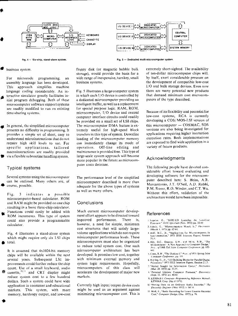
KEYBOARD
CASSETTE
rfC~~=~ DISPLAY
e:::============:S
Fig. 4 - Six-chip, stand-alone system. Fig. 5 - Dedicated multi-microcomputer system.
.. business system.
For microcode programming, an assembly language has been developed. This approach simplifies machine language coding considerably. An in-
• teractive simulator greatly facilitates initial program debugging. Both of these microcomputer software support systems are readily modified to run on existing time-sharing systems.
.. In general, the simplified microcomputer presents no difficulty in programming. It provides a simple set of short, easy to understand microinstructions that do not require high skill levels to use. For specific applications, tailored macroinstructions are readily provided
• via a flexible subroutine handling system.
Typical systems
Several systems using the microcomputer can be outlined. Many others are, of
• course, possible.
Fig. 3 indicates a possible microcomputer-based calculator. ROM and RAM might be provided on one chip resulting in a basic three-chip calculator.
• Functions could easily be added with ROM increments. This type of system could also provide a programmable calculator.
Fig. 4 illustrates a stand-alone system which might require only six LSI chips
• total.
•
It is assumed that 4xlO24-bit memory chips will be available within the next several years. Subsequent LSI improvements could further reduce the chip count. Use of a small keyboard, audio cassette, 10,1 1 and CRT display might reduce system cost to a few hundred dollars. Such a system could have wide application in consumer and educational markets. This system, with more memory, hardcopy output, and low-cost
floppy disk (or magnetic bubble bulk storage), would provide the basis for a wide range of inexpensive, turnkey, small business systems.
Fig. 5 illustrates a large'computer system in which each I I 0 device is controlled by a dedicated microcomputer pFOviding an intelligent buffer, as well as a replacement for special purpose logic. RAM, ROM, microcomputer, 110 device and central computer interface circuits could readily be provided on a small set of LSI chips. The microcomputer DMA feature is extremely useful for high-speed block transfers in this type of system. Downline loading of the microcomputer memory can immediately change its mode of operation. Off-line editing and maintenance is provided free. This type of large-scale system approach will become more popular in the future as microcomputer costs decrease.
The performance level of the simplified microcomputer described is more than adequate for the above types of systems as well as many others.
Conclusions
Much current microcomputer development effort appears to be directed toward improved performance. There is, however, a need for simple, minimum cost structures that will satisfy largevolume applications which do not require minicomputer performance levels. These microcomputers must also be organized to reduce total system cost. One such microcomputer architecture has been developed. It promises low cost, together with minimum external memory and system logic requirements. Hopefully, microcomputers of this class will accelerate the development of major new markets.
Currently high input I output device costs might be used as an argument against minimizing microcomputer cost. This is
extremely short-sighted. The availability of ten-dollar microcomputer chips will, by itself, exert considerable pressure on the development of compatible low-cost 110 and bulk storage devices. Even now there are many potential new products that demand minimum cost microcomputers of the type described.
Because of its flexibility and potential for low-cost systems, RCA is currently developing a COSI MOS-LSI version of this microcomputer - COSMAC, SOS versions are' also being investigated for applications requiring higher instruction execution rates. Both implementations are expected to find wide application in a variety of future products.
Acknowledgments
The following people have devoted considerable effort toward evaluating and developing software for the microcomputer described here: S. Heiss, A. R. Marcantonio, J.T. O'Neil, A.D. Robbi, P.M. Russo, R.O. Winder, and c.T. Wu. Without this effort, validation of the architecture would have been impossible.
References I. Lapidus. G., "MOS/ LSI Launches the Low-Cost
Processor," IEEE Spectrum (Nov. 1972) pp. 33-40.
2. Sideris, G., "Microcomputers Muscle In," Electronics (March I, 1973) pp. 63-64.
3. Hoff, M.E., Jr., "Applications for Microcomputers in Instrumentation," 1973 IEEE Intercon Papers, Session 21/ I.
4. Hitt, D.C., Ottaway, G.H., and Shirk, R.W., "The Minicomputer-A New Approach to Computer Design," PraC'. of 1968 Fall Joint Computer Conference, pp. 655-662.
5.Conn, R.W., "The Dinkiac 1," PWC'. 0[1971 Spring Joint Computer Conference, pp. 1-9.
6. ReyIing, G., Jr., "LSI Building Blocks for Parallel Digital Processors," 1973 IEEE lntercon Papers, Session 21/3.
7. "Backer Sought for Information Center," Electronics (Mar. 29, 1973) pp. 33-K
8. "Personal Lifetime Computer Foreseen," Electronics (Sept. I I. 1972) DO. 40-42.
9. KENBAK-l Computer Programming Reference Manual, KENBAK Corp. (April 1971). .
10. "Putting Data on an Ordinary Audio Recorder," The Electronic Engineer (May 1972) p. DC-9.
II. Wolf, E., "Ratio Recording for Lower Cassette Recorder Cost," CompUler Design, (Dec. 1972) p. 76.
81
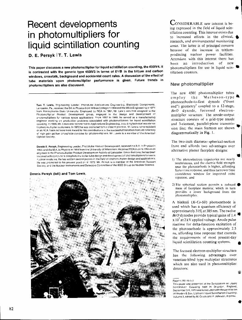
82
Recent developments in photomultipliers for liquid scintillation counting D. E. Persyk IT. T. Lewis
This paper discusses a new photomultiplier for liquid scintillation counting, the 4501V4. It is contrasted with the generic type 450lV3 in terms of E2/B in the tritium and carbon windows, crosstalk, background and accidental count rates. A discussion of the effect of tube materials upon photomultiplier performance is given. Future trends in
photomultipliers are also discussed.
Tom T. Lewis, Engineering Leader. Phototube Applications Engineering. Electronic Components. Lancaster. Pa .. received the BA in Physics from Wilkes College in 1964and the MS in Engineering in 1971 from Pennsylvania State University. Employed by RCA in 1964. Mr. Lewis was first assigned to the Photomultiplier Product Development group. engaged in the design and development of photomultipliers for various space applications. From 1967 to 1968. he served as a manufacturing engineer working on production problems associated with photomultipliers for liquid scintillation counting. In 1968. Mr. Lewis was transferred to Applications Engineering. providing technical assistance to photomultiplier customers. In 1972 he was promoted to his present position. Mr. Lewis is the recipient of an RCA Team Achievement Award for his contributions in the successful transition from lab tofactory of high gain gallium phosphide dynodes for photomultipliers. Mr. Lewis is a member of the American Optical Society.
Dennis E. Persyk, Engineering Leader, Phototube Product Development, received his B.A. in Physics in 1963, and the M.A. in Physics in 1964 from the University of Wisconsin. He joined RCA in June 1965asan engineer in the Photomultiplier Product Development Activity at Lancaster. Since that time, he has been involved with computer aided photomultiplier tube design and development of photomultipliers for use in nuclear medicine. He has written several papers in the field of photomultiplier design and applications. He was promoted to his present position in 1972. Mr. Persyk is a member of the American Vacuum Society, and the Nuclear Instruments and Detectors Committee of the IEEE Group on Nuclear Science.
Dennis Persyk (left) and Tom Lewis.
CONSIDERABLE new interest is being expressed in the field of liquid scintillation counting. This interest exists due to increased efforts in the clinical, • research, and environmental monitoring areas. The latter is of principal concern because of the increase in tritiumproducing nuclear power facilities. Attendant with this interest there has been an introduction of new photomultipliers for use in liquid scin- .. tillation counters.
New photomultiplier
The new 4501 photomultiplier tubes employ the Matheson-type" photocathode-to-first dynode ("front end") geometry! coupled to a 12-stage, BeD dynode, focussed electronmultiplier structure. The anode-output structure consists of a grid-type anode and 3-element, parallel-plane transmission line; the main features are shown diagrammatically in Fig. 1.
The two-inch diameter spherical-section front end affords two advantages over alternative planar faceplate designs: .. I) The photoelectron trajectories are nearly
isochronous, and the electric field strength near the photocathode is higher, affording faster time response, and thus narrower time coincidence window for improved noise rejection, and
2) The spherical section permits a reduced. mass of faceplate material which in turn provides a lower background from the photomultiplier.
A bialkali (K-Cs-Sb) photocathode is used which has a quantum efficiency of approximately 31 % at 385 nm. The twelve BeD dynodes provide typical gains of 1.4 • x 107 at 2 k V applied voltage. Anode pulse risetime for delta-function excitation of the photocathode is approximately 2.5 ns, affording time response that exceeds the requirements of most present-day liquid scintillation counting systems. •
The focused electron-multiplier structure has the following advantages over venetian-blind type multiplier structures which are also used in photomultiplier detectors:
Reprint RE·19-5-2 This paper was presented at the Symposium on Liquid Scintillation Counting held in Brighton, England, September 3-6,1973 and is included with the permission of Heyden & Son, Ltd from Liquid Scintillation Counting, Volume 3, edited by M. Crook and P. Johnson, in press .
•
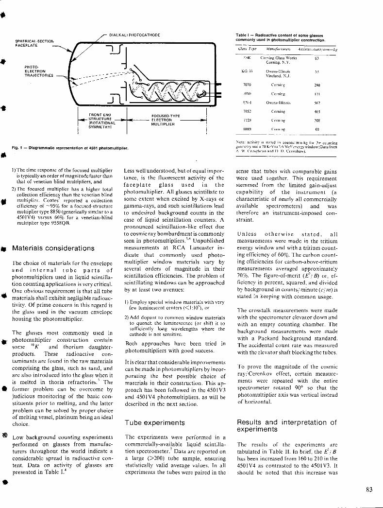
• BIALKALI PHOTOCATHODE
SPHERICAL-SECTION FACEPLATE
PHOTOELECTRON TRAJECTORIES
"t,
~ FRONT ENO +- FOCUSED_TYPE-1 STRUCTURE ELECTRON (ROTATIONAL MULTIPLIER SYMMETRY)
Fig. 1 - Diagrammatic representation 01 4501 photomultiplier. ..
,.
I) The time response of the focused multiplier is typically an order of magnitude faster than that of venetian blind multipliers, and
2) The focused multiplier has a higher total collection efficiency than the venetian blind mUltiplier. Coates' reported a collection efficiency of ~95% for a focused-structure multiplier type 8850 (generically similar to a 4501V4) versus 66% for a venetian-blind multiplier type 9558QB.
Materials considerations
The choice of materials for the envelope and internal tube parts of photomultipliers used in liquid scintillation counting applications is very critical. One obvious requirement is that all tube
,. materials shall exhibit negligible radioactivity. Of prime concern in this regard is the glass used in the vacuum envelope housing the photomultiplier.
The glasses most commonly used in photomultiplier construction contain some 40 K and thorium daughter-products. These radioactive con-taminants are found in the raw materials comprising the glass, such as sand, and are also introduced into the glass when it is melted in thoria refractories. 3 The
• former problem can be overcome by judicious monitoring of the basic constituents prior to melting, and the latter problem can be solved by proper choice of melting vessel, platinum being an ideal choice.
•
Low background counting experiments performed on glasses from manufacturers throughout the world indicate a considerable spread in radioactive content. Data on activity of glasses are presented in Table 1.4
Less well understood, but of equal importance, is the fluorescent activity of the faceplate glass used in the photomultiplier. All glasses scintillate to some extent when excited by X-rays or gamma-rays, and such scintillations lead to undesired background counts in the case of liquid scintillation counters. A pronounced scintillation-like effect due to cosmic ray bombardment is commonly seen in photomultipliersY Unpublished measurements at RCA Lancaster indicate that commonly used photomUltiplier window materials vary by several orders of magnitude in their scintillation efficiencies. The problem of scintillating windows can be approached by at least two avenues:
I) Employ special window materials with very few luminescent centers « I: 10'), or
2) Add dopant to common window materials to quench the luminescence (or shift it to sufficiently long wavelengths where the cathode is not sensitive. -
Both approaches have been tried m photomultipliers with good success.
It is clear that considerable improvements can be made in photomultipliers by incorporating the best possible choice of materials in their construction. This approach has been followed in the 450 I V3 and 4501 V4 photomultipliers, as will be described in the next section.
Tube experiments
The experiments were performed in a commercially-available liquid scintillation spectrometer. 7 Data are reported on a large (>200) tube sample, ensuring statistically valid average values. In all experiments the tubes were paired in the
Table I - Radioactive content 01 some glasses commonly used in photomultiplier construction.
Glass Trpe ManufaCTUrers A cliviry COUnt! min-kg
7740
KG-33
7070
7050
EI'-I
7052
7720
0080
Corning Glass Works Corning. ~.Y.
Owens-Illinois Vineland. !\:.J.
Corning
Corning
Owens-Illinois
Corning
Corning
Corning
83
53
290
171
567
465
208
60
~ote; activity is stated in counts/ min-kg for 2rr counting geometry and a 70 KeY to 2.6 MeV energy window (Data from A. W. Consy!man and D. D. Crawshaw) .
sense that tubes with comparable gains were used together. This requirement stemmed from the limited gain-adjust capability of the instrument (a characteristic of nearly all commercially available spectrometers) and was therefore an instrument-imposed constraint.
Unless otherwise stated, all measurements were made in the tritium energy window and with a tritium counting efficiency of 60%. The carbon counting efficiencies for carbon-above-tritium measurements averaged approximately 70%. The figure-of-merit (E-18) or, efficiency in percent, squared, and divided by background in countsl minute (el m) is stated in keeping with common usage_
The crosstalk measurements were made with the spectrometer elevator down and with an empty counting chamber. The background measurements were made with a Packard background standard. The accidental count rate was measured with the elevator shaft blocking the tubes.
To prove the magnitude of the cosmic ray I Cerenkov effect, certain measurements were repeated with the entire spectrometer rotated 90° so that the photomultiplier axis was vertical instead of horizontal.
Results and interpretation of experiments
The results of the experiments are tabulated in Table II. In brief, the E- 18 has been increased from 160 to 210 in the 450lV4 as contrasted to the 4501V3. It should be noted that this increase was
83
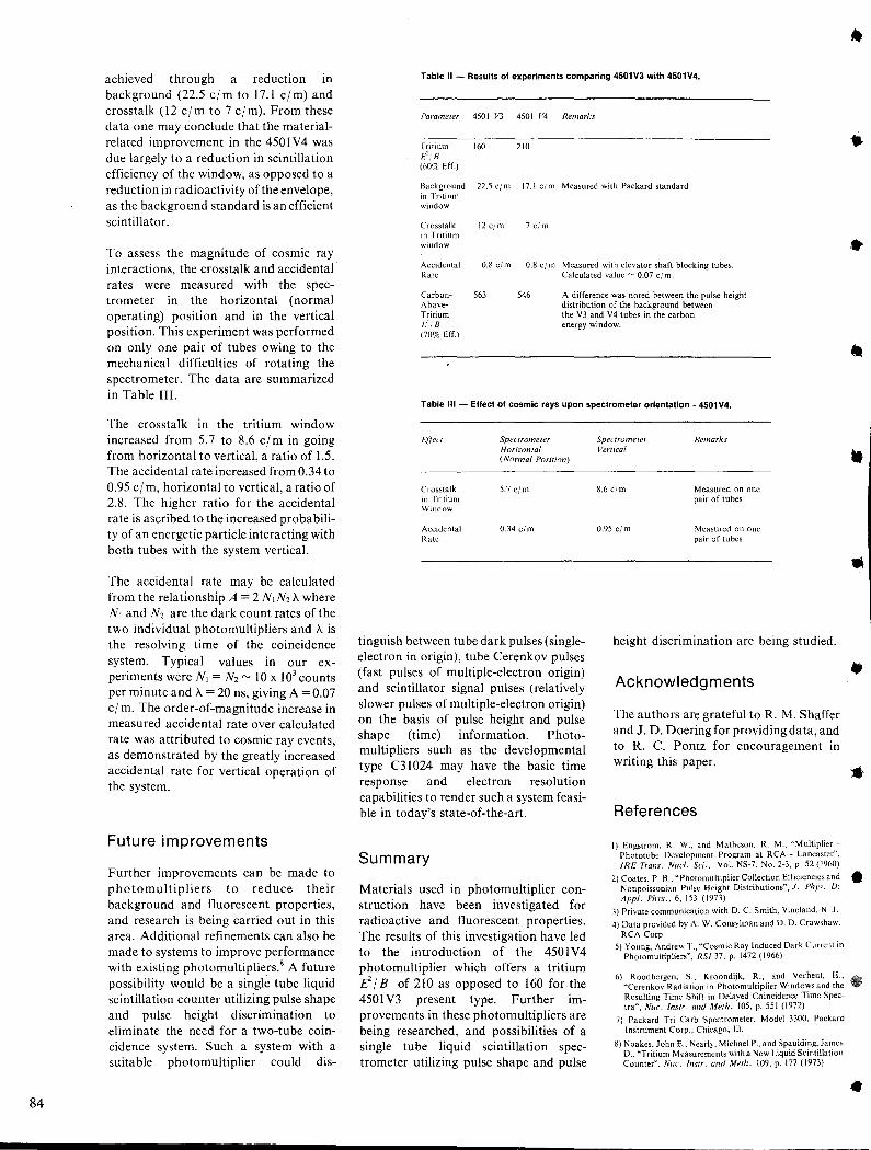
84
achieved through a reduction in background (22.5 cl m to 17.1 cl m) and crosstalk (12 cl m to 7 cl m). From these data one may conclude that the materialrelated improvement in the 450lV4 was due largely to a reduction in scintillation efficiency of the window, as opposed to a reduction in radioactivity of the envelope, as the background standard is an efficient scintillator.
To assess the magnitude of cosmic ray interactions, the crosstalk and accidental rates were measured with the spectrometer in the horizontal (normal operating) position and in the vertical position. This experiment was performed on only one pair of tubes owing to the mechanical difficulties of rotating the spectrometer. The data are summarized in Table III.
The crosstalk in the tntlUm window increased from 5.7 to 8.6 c/m in going from horizontal to vertical, a ratio of 1.5. The accidental rate increased from 0.34 to 0.95 cl m, horizontal to vertical, a ratio of 2.8. The higher ratio for the accidental rate is ascribed to the increased probability of an energetic particle interacting with both tubes with the system vertical.
The accidental rate may be calculated from the relationship A = 2 NIN2 A where NI and N2 are the dark count rates of the two individual photomultipliers and A is the resolving time of the coincidence system. Typical values in our experiments were NI = N2 ~ 10 X 103 counts per minute and A = 20 ns, giving A = 0.07 cl m. The order-of-magnitude increase in measured accidental rate over calculated rate was attributed to cosmic ray events, as demonstrated by the greatly increased accidental rate for vertical operation of the system.
Future improvements
Further improvements can be made to photomultipliers to reduce their background and fluorescent properties, and research is being carried out in this area. Additional refinements can also be made to systems to improve performance with existing photomultipliers.8 A future possibility would be a single tube liquid scintillation counter utilizing pulse shape and pulse height discrimination to eliminate the need for a two-tube coincidence system. Such a system with a suitable photomultiplier could dis-
Table II - Results of experiments comparing 4501V3 with 4501V4.
Parameler 450 I r'3 450 I V4 Remarks
Tritium 160 210 /0' B (60S< Eff.)
Background 22.5 eim 17.1 elm Measured with Packard standard in Tritium window
Crosstalk in Tritium window
12 elm 7 elm
Accidental Rate
0.8 el m 0.8 cj m Measured with elevator shaft blocking tubes. Calculated value - 0.07 elm.
CarbonAboveTritium L,c/B (70% Eff.)
563 546 A difference was noted between the pulse height distribution of the background between the V3 and V4 tubes in the carbon energy window.
Table III - Effect of cosmic rays upon spectrometer orientation - 4501V4.
Effect Spectrometer Horizontal (Normal Position)
Crosstalk 5.7e/m in Tritium Window
Accidental 0.34 el m Rate
tinguish between tube dark pulses (singleelectron in origin), tube Cerenkov pulses (fast pulses of multiple-electron origin) and scintillator signal pulses (relatively slower pulses of multiple-electron origin) on the basis of pulse height and pulse shape (time) information. Photomultipliers such as the developmental type C31024 may have the basic time response and electron resolution capabilities to render such a system feasible in today's state-of-the-art.
Summary
Spectrometer Remarks Vertical
8.6 elm Measured on one pair of tubes
0.95 el m Measured on one pair of tubes
height discrimination are being studied.
Acknowledgments
The authors are grateful to R. M. Shaffer and J. D. Doering for providing data, and to R. C. Pontz for encouragement in writing this paper.
References
I) Engstrom, R. W., and Matheson, R. M., "Multiplier -Phototube Development Program at RCA - Lancaster", IRE Trans. Nucl. Sc; .. Vol. NS-7. No. 2-3. p. 52 (1960)
•
Materials used in photomultiplier construction have been investigated for radioactive and fluorescent properties. The results of this investigation have led to the introduction of the 450lV4 photomultiplier which offers a tritium If I B of 210 as opposed to 160 for the 450 I V3 present type. Further improvements in these photomultipliers are being researched, and possibilities of a single tube liquid scintillation spectrometer utilizing pulse shape and pulse
2) Coates, P. 8., "Photomultiplier Collection Efficiencies and e Nonpoissonian Pulse Height Distributions", J. Phys. D: Appl. Phys .• 6, 153 (1973)
J) Private communication with D. C. Smith, Vineland, N. J. 4) Data provided by A. W. Consylman and D. D. Crawshaw.
RCA Corp. 5) Young, Andrew T., "Cosmic Ray Induced Dark Current in
Photomultipliers". RS/37. p. 1472 (1966)
6) Roodbergen. S.. Kroondijk, R., and Verheul, H .. "Cerenkov Radiation in Photomultiplier Windows and the Resulting Time Shift in Delayed Coincidence Time Spectra". Nuc. Instr. and Meth. 105. p. 551 (1972)
7) Packard Tri Carb Spectrometer. Model 3300, Packard Instrument Corp., Chicago, Ill.
S) Noakes, John E .. Nearly, Michael P., and Spaulding. James D .. "Tritium Measurements with a New Liquid Scintillation Counter", Nuc. Instr. and Meth. 109, p. 177 (1973)
•
..
•
..
•
•
•
•
•
Pen and Podium
Recent RCA technical papers and presentations
Both published papers and verbal presentations are indexed. To obtain a published paper borrow the journal in which it appears from your library or write or call the author for a reprint. For information on unpublished verbal presentations write or call the author. (The author's RCA Division appears parenthetically after his name in the subject-index entry.) For additional assistance in locating RCA technical literature contact RCA Technical Communications, Bldg. 204-2, Cherry Hili, N.J. (Ext. PC-4256).
This index is prepared from listings provided bimonthly by RCA Division Technical Publications Administrators and Editorial Representatives-who should be contacted concerning errors or omissions (see inside back cover)
Subject Index categories are baled upon standard announcement categories used by Technical Information Systems. Bldg, 204-2, Cherry Hili, N.J.
Subject Index
Titles of papers are permuted where necessary to bring significant keyword(s) to the left for easier scanning. Authors' division appears parenthetically after his name.
SERIES 100 BASIC THEORY & METHODOLOGY
105 Chemistry organic, inorganiC, and physical.
BARREL REACTOR, An investigation of convective effects In a -B.J. Curtis, J.P. Dismukes (Labs,Pr) 4th Int'I Conf. on Chemical Vapor Deposition, Boston, MA; 1017-12/73
CHEMICAL CATALYTIC SYSTEMS for plating onto dielectric substrates, Electron microscope investigations of - M. Schlesinger, N. Feldstein (Labs,Pr) Electrochemical Soc. Mtg., Boston, MA; 1017-12/73
CHEMICAL-VAPOR DEPOSITION, Evaluation 01 an organometallic approach to garnet - J.P. Dismukes, J. Kane (Labs,Pr) 4th Int'I Conf. on Chemical Vapor Deposition, Boston, MA; 1017-13173
SPUTTERING AND TRANSPORT MECHANISMS on target etching and thin 111m growth in rf systems, Comments on the inlluence at - J.L. Vossen (Labs,Pr) Vacuum, Vol. 23, No.5, pp. 175
VAPOR DEPOSITION of cathodoluminescent phosphor layers, Chemical - J.P. Dismukes, J. Kane, B. Binggeli, H.P. Schweizer (Labs,Pr) 4th Int'I Conf. on Chem. Vapor Deposition, Boston, MA; 1017-12/73
110 Earth and Space SCiences geology, geodesy, meteorology, atmospheric phYSics, astronomy, outer space environment.
NEW TECHNOLOGY, Environment, energy and the need lor - V.L. Dalal (Labs,Pr) Energy Conversion, Vol. 13, pp. 85-94; 73
125 Physics electromagnetic field theory, quantum mechanics, basic particles, plasmas, solid state, optics, thermodynamics: solid mechanics, fluid mechanics, acoustics.
ACOUSTIC SURFACE WAVE VELOCITY MEASUREMENT, Frequency variational method lor - M. Toda (Labs,Pr) Conf. of acoustical soc. of Japan, Nagoya, Japan; 10/18-20173
CARRIER INJECTION, Trapped plasma triggered by - H. Kawamoto (Labs,Pr) Appl. Phys. Lett., Vol. 23, No.5, pp. 271-272; 9/73
Continuous spatial average In a diffuse sound lield, Effectiveness 01 - M.S. Corrington (ATL,Cam) J. of the Acoustical Soc. of America, Vol. 54, No.3, pp 813-814; 9/73
IRRADIANCE in turbulent air: diffraction cutoff, Saturation of - D.A. deWol1 (Labs,Pr) Fall Mtg. 01 the Optical Soc. of America, Rochester, NY; 10/9-12/73
PHONON TRANSPORT theory for structural phase transitions, On the Interpretation of -R. Klein, (Labs,Pr) Swiss Phys. Soc. Mtg., Lugano, Switzerland, 10/19-20173
POLARITONS, Anisotropic exciton - G. Harbeke (Labs,Pr) Swiss Physical Soc. Mtg., Lugano, Switzerland; 10/19-20173
SOFT ACOUSTIC MODES In elastic layers with electrostatic surface forces - RK Whener (Labs,Pr) Swiss Phys. Soc. Mtg. Lugano, Switzerland; 10/19-20173
SPHERICAL WAVES, Strong irradlance Iluctuations In turbulent air: II. - D.A. deWolf (Labs,Pr) J. Opt. Soc. Am., Vol. 63. No. 10; pp. 1249-1253; 10173
TURBULENT FLOWING PLASMA, The moment relations, Transporf effects in a _ I.P.
Shkarofsky (Ltd,Can) Plasma Physics, Vol. 15, No.6; 6/73
130 Mathematics basic and applied mathematical methods.
NETWORK EQUATIONS, Exact N-solution of nonlinear lumped self-dual - R. Hirota (Labs,Pr) J. Phys. Soc. Japan, Vol. 35, No.1, pp. 289-294; 7173
NONLINEAR WAVE EQUATION, Exact envelopewsoliton solutions of a - R. Hirota (Labs,Pr) J. Math. Phys., Vol. 14, pp. 805-809, No.7; 7173
PROBABILITY - O.G. Allen (MSRD,Mrstn) 17th Annual Symp. of the ASOC Philadelphia Section, Mariott Motor Inn, Philadelphia, PA; 11/14173
SINE-GORDON EQUATION, Exact threesoliton solution of the two-dimensional - R. Hirota (Labs,Pr) Mtg. of the Phys. Soc. of Japan, Keio Univ., Japan; 11/22-25173
WAVE EQUATION of long waves in shallowwater and in nonlinear lattices, Exact N. soliton solutions of the - R. Hirota (Labs,Pr) J. Math. Phys., Vol. 14, No.7, pp. 810-814; 7173
150 Environmental and Human Factors
influence of physical environment and/or human users on engineering design, life support in hostile enviornments.
VIBRATION ANALYSIS, Combined modal and analog - J.M. Cies (AED, Prj 44th Shock and vibration Symp.; Symp. Bulletin; Houston, Texas; 12/4-7173
VISUAL CAPACITY - an image quality descriptor for display evaluation - R.w. Cohen, I. Gorog (Labs,Pr) 1973 Electrophotography Conf., Washington, DC; 10/27173
160 Laboratory Techniques and Equipment
experimental methods and equipment, lab facilities, testing, data measurement, spectroscopy, electron microscopy, dosimeters.
ION SCATTERING SPECTROMETRY below 10keV - W.1. Harrington, R.E. Honig (Labs,Pr) 144th Mtg. of the Electrochemical Soc., Boston, MA; 1017-12/73
SEMICONDUCTOR PROBLEMS, Use 01 the infrared sensitivity of the silicon vidicon to diagnose - R.A. Sunshine, N. Goldsmith (Labs,Pr) IEEE 1973 Northeast Electronics Research & Eng. Mtg., (NEREM); 11/12-14/73
THERMAL CONDUCTIVITY of thin samples, Measurement of - E. Belohoubek, J. Mitchell, F. Wozniak (Labs,Pr) J. Am. Ceram. Soc., Vol. 56, No. 10, pp. 391; 7173
170 Manufacturing and Fabrication
production techniques for materials, devices and equipment.
INTERCONNECTIONS - B.R. Schwartz (MSRD,Mrstn) Electromechanical Design 11-12/73
PATTERN GENERATION for micro electronics, The use of electrons and light in _ H.O. Hook (Labs,Pr) Kodak Seminar, Atlanta, GA; 10/29-30173
MULTILEVEL METALLIZATION, Processes for - J.L. Vossen, G.L. Schanble, W. Kern (Labs,Pr) 1973 Am. Vacuum. Soc. Symp. New York; 10/10173
PHOTO-LITHOGRAPHY and other nonelectron beam lithography, The capabilities and limitations of - H.O. Hook (Labs,Pr) 20th Nat'l Vacuum Soc. Symp., NYC: 10/9-13/73
RELIEF-PHASE HOLOGRAMS for prerecorded video, Replication of - R.A. Bartolini, N. Feldstein, R.J. Ryan (Labs,Pr) J. Electrochem. Soc., Vol. 120, No. 10, pp. 1408-1413; 10173
175 Reliability, Quality Control and Standardization
value analysis, reliability analysis, standards for design and production.
LOGISTICS management, Industrial - J.w. Hurley (MSRD,Mrstn) Soc. of Logistics Engineers, Balmaw, NJ; 10/17173; Industrial Logistics Management Seminar, Philadelphia Chapter of The Society of Logistics Engineers, Univ. of Pa.; 12/6173
QUALITY APPLICATIONS, ComputerizedH. Wintling (MSRD,Mrstn) 17th Annual Symp., Phila. Section ASOC; 11/14173
THICK-FILM RESISTOR STABILITY as a function of processing and laser trimming parameters - K.R. Bube (Labs,Pr) SEMICON/EAST, Nassau Colliseum, Long Island; 1/2-4/73
180 Management and Business Operations
organization, scheduling, marketing, personnel.
LEADERSHIP in science and technology, The need for - M.P. Bachynski (Ltd,Can) IEEE Int'I Electrical, Electronics Conf., Toronto; 10173
SERIES 200 MATERIALS, DEVICES, & COMPONENTS
205 Materials (Electronic)
preparation and properties of conductors, semi-conductors, dielectrics, magnetic, electro-optical, recording, and electro-magnetic materials.
(AlGa) As-GaAs heteroiunctions, Measurements of refractive Index step and of carrier confinement at - H. Kressel, H.F. Lockwood, J.K. Butler (Labs,Pr) J. App. Phys., Vol. 44, No.9, pp. 4095-4097; 9/73
AgBr, Evidence for electron-hole-droplet formation in - W. Czaja, C.F. Schwerdtfeger
85
(Labs,Pr) Swiss Phys. Soc. Mtg., Lugano, Switzerland; 10/19-20173
Be12Ge020, Bi12Si020, Bi12(GeO.SSiO.S)020 - W. Rehwald (Labs,Pr) J. Appl. Phys. Vol. 44, No.7, pp. 3017-3021; 7/73
Bi-BASED GARNET films for magneticbubble devices with magneto-optic applications, New - A. Akselrad, R.E. Novak, D.L. Patterson (Labs,Pr) 19th Conf. on Magnetism & Magnetic Materials, Boston, MA; 11/13173
CARBON CONCENTRATION ON BeO and its effects on secondary electron emission, Electron-beam induced reduction of - B. Goldstein (Labs,Pr) Surface science Vol. 39, No.2, pp. 261-271; 9173
PHOSPHORS, Cathode-ray-tube; principles and applications - S. Larach, A.E. Hardy (Labs,Pr) Proc. IEEE, Vol. 61, No.7, p. 915-926; 7/73
CATHODOCHROMIC materials and applications - BW. Faughnan, I. Gorog, P.M. Heyman, I. Shidlovsky (Labs,Pr) Proc. IEEE, Vol. 61, No.7, pp. 927-941; 7/73
CdCr2X4 (X=S and Se) grown by chemical vapor transport, Composition of - F. Okamoto, K. Ametan;' T. Oka (Labs,Pr) Mtg. on "Chemical Vapor tgg,ppoit. of Tech.,
Japan; 10/16-19/73
CdS AND NAPHTHALENE monocrystals, Limitation on deep trapping of injected space charge in - J. Dresner, M. Campos, R.A. Moreno (Labs,Pr) J. Appl. Phys., Vol. 44, No. 8. pp. 3708-3712
CdS excited by high voltage RF current pulses, Intense recombination radiation and room temperature lasing in - F.H. Nicoll (Labs,Pr) Appl. Phys. Lett., Vol. 2, No.8, pp. 465-466; 10/15/73
CRYSTAL Gd2(MoO 4)3 ' Variable delay devices using ferroelaslic and ferroelectric -M. Toda, S. Tosima, E. Shima, T. Iwasa (Labs,Pr) IEEE Trans. Sonic &IEEE Trans. Sonic & Ultrasonics, Vol. SU-20, No.4, pp. 376-379; 10173
Dy(OH) and Ho(OH) :, Magnetic ordering in - c.l Catanese, I?E. Meissner (Labs,Pr) Phys. Rev. B, Vol. 8, No.5, pp. 2060-2074; 9/1/73
ELECTRONIC MATERIALS by means of cosputtering, Automation of the search for -J.J. Hanak (Labs,Pr) 1973 Int'I Conf. on sputtering and its applications, Montpellier, France; 10/2-5/73
GaAs:Ge prepared by liquid phase epitaxy, Electro and Photoluminescence of - H. Kressel, M. Ellenberg (Labs,Pr) Appl. Phys. Lett., Vol. 23, No.9, pp. 511-513; 11/1/73
GaN, Luminescence of insulating Be-doped and Li-doped - J.1. Pankove, M.T. Duffy, E.A. Miller, J.E. Berkeyheiser (LabS,Pr) J. Lumin. Vol. B, No.1, pp. 89-93; 9/73
Ge/Cs/O (100) surtace, Structural analysis and photoemissive response of the - B. Goldstein, R.U. Martinelli (Labs,IPr) J. Appl. Phys., Vol. 44, No.9, pp. 4244-4245; 9/73
HOMOEPITAXIAL SILICON, High-frequency electron conductivity mobility in vapor-phase - C.P. Wen, Y.S. Chiang, A.F. Young, A. Presser (Labs,Pr) Appl. Phys. Lett., Vol. 23, No.7, pp. 390-391; 1011173
Ino SGaO sP prepared by vapor-phase epllaxy, (uminescence from - H. Kressel, C.J. Nuese, I. Ladany (Labs,Pr) J. App. Phys., Vol. 44, No.7, pp. 3266-3272; 7/73
ION DEPLETION OF GLASS at a blocking anode I. theory and experimental results for alkali silicate glasses - D.E. Carlson (Labs,Pr) Glass Div. 1974 Fall Mtg., Bedford Springs, PA; 10/10-12/73
86
ION DEPLETION OF GLASS at a blocking anode II. properties of ion-depleted glassesD.E. Carlson, KW. Hang, G.F. Stockdale (Labs,Pr) Glass Div. 1973 Fall Mtg., Bedford Springs, PA; 10/10-12/73
ION IMPLANTATION technology - C.W. Mueller (Labs,Pr) N.Y. Metropolitan AreaMtg. of IEEE. Nutley, NJ; 10/11173
LATTICE SOLITONS in nonlinear lumped networks, Theoretical and experimental studies of - R. Hirota, K. Suzuki (Labs,Pr) Proc. IEEE, Vol. 61, No. 10 pp. 1483-1491; 10/73
LIQUID CRYSTAL storage materials, Light scattering characteristics in - D. Meyerhofer, E.F. Pasierb (Labs,Pr) Mol. Cryst. & Liquid Cryst., Vol. 20, pp. 279-300; 1973
MATERIALS INTEGRATION through heteroepitaxial growth on insulating substrates - GW. Cullen, M.T. Duffy, C.C. Wang (Labs,Pr) Electrochem, Soc. 3rd Int'I Conf. on CVD, Boston, MA; 1017173
MOS I/O devices - L. Dillon (ATL,Cam) Hardened guidance and weapon delivery tech. Mtg., Orlando, FL; 10/17/73
NATRIUMHYPEROXIDE, Molekul-und gitterschwingungen im - M. Bosch, W. Kanzig, E.F. Steigmeier (Labs,Pr) Physik der kondensierten materise, Vol. 16, pp.107-112; 1973
NICKEL PARTICLES, Blocking temperature effects in fine - J.1. Gittleman, B.A Abeles (Labs,Pr) 19th Conf. on Magnetism and Magnetic Materials, Boston, MA; 11/13-16/73
NON-INDIUM METALLIC BOND tested by welding acoustic sheer-wave transducers to paratellurite, A room-temperature - J.D. Knox (Labs,Pr) RCA Review., Vol. 34, No.2, pp. 369-372; 6/73
NONMETAL THIN FILMS, RF bias evaporation (Ion plating) of - J.G. Davy, J.J. Hanak (Labs,Pr) 29th Am. Vacuum Soc. Symp., NYC; 10/73
POLYCRYSTALLINE SILICON, Low lemperature growlh and properties of - Y.S. Chiang (Labs,Pr) 1973 Semiconductor silicon symp. record pp. 285-291; 73
POLYMERS OF METHYL ISO-PROPENYL KETONE, The interaction of 5 keV electrons with 1. mechanlsticaspects-A.W. Levine, M. Kaplan (Labs,Pr) SPE third Conf. on Photopolymers, Ellenville, NY; 10/73
POLYMERS OF METHYL ISOPROPENYL KETONE ,The interaction of 5 keV Electrons with III approaches 10 device fabrication -AW. Levine, M. Kaplan, E.S. Poliniak (Labs,Pr) Soc. of plastiCS Eng. Conf. on Photopolymers, Ellenville, NY; 10/73
POLYMERS of 1-methylvinyl methyl ketone, The inleraction of 5 keV electrons with - A. W. Levine, M. Kaplan (Labs,Pr) SPE Conf. Principles, Processes, & Materials, Ellenville, NY; 10/24-26173
~b2_S3C evaporated films, Charge transport In Wronski (Labs,Pr) Electric charge storage and transport in dielectrics, pp. 382-388; 1973
SCREENING of melal film defects by current noise measurements - J.L. Vossen (Labs,Pr) Appl. Phys. Lett., Vol. 23, No.6, pp. 287-289; 9/15/73
SILICON CVD SYSTEMS, A survey of convective instabilities in - J.P. Dismukes, B.J. Curtis (Labs,Pr) 1973 Semiconductor Silicon Symp. ibid pp. 258-270; 73
SILICON DIOXIDE, Injection and removal of ions through the free surface of- R. Williams (Labs,Pr) Dept. of Elec. Eng., Princeton Univ., 9/19/73
SILICON, Field-effect electroluminescence in - A.M. Goodman (Labs,Pr) RCA Review,
Vol. 34, No.3, pp. 429-441; 9/73
SILICON using dichlorosilane: Growth on single-crystal hemispheres, Epitaxial growth of - N . Goldsmith, P.H. Robinson (Labs,Pr) RCA Review, Vol. 34, No.2; pp. 358-368; 6/73
TODA LATTICE, Higher conservation laws of Ihe - R. Hirota (Labs,Pr) Mtg. of the Physical Soc. of Japan, Keio Univ .. Japan; 11/22-25/73
In 1 Ga P for P-N junction eleclroluminescence I: material preparation, Vapor growth of - A.G. Sigai, C.J. Nuese, R.E. Enstrom, T. Zamerowski (Labs,Pr) J. Electrochem. Soc., Vol. 120, No.7, pp. 947-955; 7/73
In1_xGaxP for P-N junction electroluminescence II, Vapor growth of: luminescence characteristics - C.J. Nuese, A.G. Sigai, M.S. Abrahams, J.J. Gannon (Labs,Pr) J. Electrochem. Soc., Vol. 120, No. 7, pp. 956-965; 7/73
WIGNER CRYSTAL, Collective modes of a Iwo-dimensional - R.S. Crandall (Labs,Pr) Phys. Rev. A., Vol. 18, No.4, pp. 2136-2142;
.10/73
Y 203:Eu(red) and L"20 S:Pr(green) on TV glass, quartz, and sapp~ire, Chemical vapor deposition of cathodoluminescent phosphor layers of - J. Gerber, J.P. Dismukes, R.J. Ulmer (Labs,Pr) 4th Int'I Conf. on Chemical Vapor Deposition, Boston, MA; 10/7-12173
ZnO, Charge carrier transport in - H. Kiess (Labs,Pr) 2nd Inl'l Conf. on Electrophotography Washington, D.C.; 10/24-27/73
ZnO FILMS, RF-spullered - HW. Lehmann, R. Widmer (Labs,Pr) 20th Nat'l Vacuum Symp., New York; 10/9-12/73
ZnO: Investigation of the charge decay on the photo-conductive properties of ZnO-binder layers with blocking conlracts - H. Kiess (Labs,Pr) Electric charge Storage and Transport in Dielectrics, pp. 389-398; 1973
ZnO SHEAR-WAVE TRANSDUCERS, RF sputtering of - HW. Lehmann, R. Widmer, (Labs,Pr) J. Appl. Phys., Vol. 44, No.9, pp. 3868-3879; 9/73
210 Circuit Devices and Microcircuits
electron tubes and solid-state devices (active and passive); integrated, array and hybrid microcircuits, field-effect devices, resistors and capacitors, modular and printed circuits, circuit interconnection, waveguides and transmission lines.
ACOUSTIC SURFACE WAVE COMPONENTS in EW systems - D.A. Gandolfo, C.L. Grasse, GD. O'Clock, Jr (EASD,Van Nuys) Int'I Seminar Acoustic Surface Wave Devices, Aviemore, Scotland; 9/27/73
ACOUSTIC SURFACE WAVE FILTERS, MUlti-strip coupled D.H. Hurlburt (Ltd,Can) IEEE Ultrasonic Symp., Monterey, Calif.; 11/73
AVALANCHE DIODES for radiation monitoring, Large area reach-through - P. Webb (Ltd,Can) IEEE nuclear science symp., San Francisco; 11/73
CCD IMAGING - state of Ihe art - J.E. Carnes (Labs,Pr) 1973 European solid state device research cont., Munich, Germany; 9/18-22/73
CCD's state-of-the-art and processing W.F. Kosonocky (Labs,Pr) SEMICON/EAST, Westbury, Long Island; 10/2/73
Cr-Cu AND Cr-Cu-Cr thin film metallization - J.J. O'Neill, J.l. Vossen (Labs,Pr) J. Vac.
SCI & Techno!., Vol. 10, No.4, pp. 533-538; 7-8/73
EPITAXIAL STRUCTURES, Synlhesis of multilayer - H. Kressel (Labs,Pr) Semicon Easl, Nassau Coliseum, New York; 10/2/73
GaAs FET for high power amplifiers at. microwave frequencies - l.S. Napoli, J.J. Hughes, W.F. Reichert, S. Jolly (Labs,Pr) 1973 Nat'l Telecommunications Conf., Allanta, GA; 11/26-28/73
GaAs IMPATT oscillalor and amplifier noise, A study of millimeter-wave - K.P. Weller (Labs,Pr) IEEE Trans. Electron Devices, Vol. ED-20, No.6, pp. 517-521; 6173
HIGH SPEED AVALANCHE PHOTODIODES • and a review of the stale-of-the-art, Factors affecting the ultimate capabilities of - R.J. Mcintyre, (Ltd,Can) Int'I Electron Devices Conf., Washington; 12/73
IMAGE TUBE in ultra high-speed frame and streak photography - R.W. Engstrom, R.W. Fitts (EC,Har) SPIE 171h Annual Technical ~~g7:~;/~iqUipment Display, San Diego, CA; ..
MOSFET's, Low-frequency l/f noise in - R.S. Ronen (Labs,Pr) RCA Review, Vol. 34, No.2, pp. 280-307; 6/73
MULTILEVEL METALLIZATION, Processes for - J.L. Vossen, G.l. Schnable, W. Kern (Labs,Pr) Am. Vacuum Soc. Mat'I Symp., NYC; 10/9-12/73
PHOTOMULTIPLIERS for liquid scintillation .. counting, Recent developments in - D.E. LPersyk, T.T. Lewis (EC,Har) Symp. on Liquid Scintillation Counting, Brighton, England; 9/3-6/73
PIN diode phaser for millimeter wavelengths, A distributed - B.J. Levin, G. Weidner (ATL,Cam) Microwave J., Vol. 16, No. 11 pages 42-44; 11/73
POWER TRANSISTORS, Infrared observa-" tion of current distributions in large area -RA Sunshine (Labs,Pr) 1973 Annual mtg. of the Industry Applications Soc., Milwaukee, Wis; 10/8-11/73
RELAXATION SEMICONDUCTORS, Transporl in - H. Kiess, A. Rose (Labs,Pr) Phys. Rev. Lett., Vol. 31, No.3, pp. 153-154; 7/16/73
SHOCKLEY DIODES of HaAs and GaAs1_xP x - , Electroluminescent - C.J. Nuese, J.J.
Gannon, H.F. Gossenberger, C.R. Wronski (Labs,Pr) J. Elect. Mat., Vol. 2, No.4, pp. 571-599; 1973
• SILICON COLD CATHODE, Scanning-beam performance from a negative-eleclronaffinity activated - AD. Cope, E. Luedicke, .. J.P. Carroll (Labs,Pr) RCA Review, Vol. 34, No.3, pp. 408-428; 9/73
TRANSFERRED ELECTRON DEVICES, Space-charge instabilities in - B.S. Perlman (Labs,Pr) RCA Review, Vol. 34, No. pp. 457-488; 9/73
TRAPATT comes of age - a status reportVA Mikenas (MSRD,Mrstn) IEEE G~1~~~~7~AP Philadelphia Section Mtg.,;.
TRAPATT diodes, Analytic and experimental techniques for evaluating transient thermal characteristics of - J.H. Bowen, M.E. Breese, VA Mikenas, M. Weiss (MSRD,Mrstn) -1973 IEEE Int'l Electron Devices Mtg., Washinglon, DC; 12/3-5/73
215 Circuit and Network Designs
analog and digital functions in electronic equipment; amplifiers, filters, modulators, microwave circuits, A-O
•
•
converters, encoders, oscillators, switches, masers, log ic networks, timing and control functions, fluidic circuits.
.. A/D AND D/A CONVERTERS for multilevel fast data transmission - K. Feher (Ltd,Canada) Ecole Poly technique lederale de Lausanne; 10/73
IMPATT OSCILLATOR, High-frequency silicon-on-sapphire - C.P. Wen, Y.S. Chiang, A.F. Young (Labs,Pr) Proc. IEEE, Vol. 61, No. 6, pp. 794-795; 6/73
LONG PULSE SWITCH and power amplifier • tubes for phased array radar-J.T. Mark, R.E.
Byram (EC,Har) 11th Modulator Symp. of IEEE Advisor Group on Electron Devices, New York; 9/18-19/73
PSK MODULATOR design for a hybrid analog/digital environment - K. Keher (Ltd,Can) 11th modulator symp., New York; 9/73
220 Energy and Power Sources
batteries, solar cells, generators, reactors, power supplies.
SOLAR CELLS, Temperature, illumination and fluence dependence of current and voltage in electron-irradiated - T.J. Faith, A.F. Oberchain (AED,Pr) IEEE Photovoltaic Specialists Conf.; Palo Alto, Calif; 11/15/73
240 Lasers, Electro-Optical and
.' Optical Devices
deSign and characteristics of lasers, components used with lasers, electro-optical systems, lenses, etc. (excludes: masers).
BUBBLE DOMAINS, Lensless optical detection of - R. Shah bender, J. Druguet (Labs,Pr)
• RCA Review, Vol. 34, No.3, 385-400; 9/73
CO2 laser technology at RCA Limited - R.A. Crane (Ltd,Can) Seminar on lasers and their military applications (NATO Defence Research Group) Defence Research Establishment, Valcartier; 10173
ELECTRO-OPTIC WAVEGUIDES - J.M. Hammer (Labs,Pr) ONR Program Review, Washington, D.C.; 10/2-4/73
• INJECTION LASERS, Experimental properties of: IV, modes of large cavity with sawed sides - H.S. Sommers (Labs,Pr) J. Appl. Phys., Vol. 44, No.8, pp. 3601-3608; 8173
LASER DIODES, Heterojunction - H. Kressel (Labs,Pr) NEREM Seminar, Boston, MA; 11/73
LASER DIODES, Red-light-emitting • AlxGa1_xAsheterojunction - H. Kressel, F.Z.
Hawrylo (Labs, PrO J. Appl. Phys., Vol. 44, No. 9, pp. 4222-4223; 9/73
•
LASER MIRRORS, Inexpensive - A.H. Firester, M.E. Heller, J.P. Wittke (Labs,Pr) Am. J. Phys. Vol. 41, pp. 1202; 10/73
LASER SCANNERS, Frequency response of, and its optimization through apodlzation _ R.W. Cohen, I. Gorog (Labs,Pr) J. Optical Soc., Vol. 63, No.9, pp. 1071-1079; 9/73
METAL-VAPOR LASERS, Noblest of - K. Hernqvist (Labs,Pr) Laser Focus., pp. 39-40; 9/73
MICRO FRESNEL ZONE PLATES, Properties and fabrication of - A.H. Firester (Labs,Pr)
Appl. Opt .. Vol. 12, No.7, pp. 1698-1702; 8/73
MODULATION of lasers, A comparative evaluation between internal and external polarization - A.L. Waksbert (Ltd.,Can) IEEE J. 01 Quantum Electronics, Vol. 9, No. 11; 11/73
MODULATOR, Fast electro-optic waveguide deflector - J.M. Hammer, D.J. Channin, M.T. Duffy (Labs,Pr) Appl. Phys. Lett., Vol. 23, No. 4, pp. 176-177; 8/15/73
OPTICAL FILTERS, Selection of objective functions for optimization of - R.L. Crane (Labs,Pr) IEEE Circuits and System SOCiety's Computer-Aided Network Design Comm. Workshop, Carefree, AR; 9/24-25/73
VENTED-BORE-He-Cd lasers - K.G. Hernqvist (Labs,Pr) RCA Review, Vol. 34, No.3, pp. 401-407; 9173
VOLUME HOLOGRAPHY, science and applications - D.L. Staebler (Labs,Pr) Second Int'I Conf. on Electrophotography, Washington, D.C.; 10/24-27173
VOLUME PHASE HOLOGRAM recording medium, A new - A. Bloom, R.A. Bartolini (Labs, Pr) Optical Soc. of America Annual Mtg., Rochester, NY; 10173
245 Displays equipment for the display of graphic,
alphanumeric, and other data in communications, computer, military, and other systems, CRT devices, solid state displays, holographic displays, etc.
DISPLAY, Blue-green numeric using electro-luminescent GaN - J.1. Pankove (Labs,Pr) RCA Review, Vol. 34, No.2, pp. 336-343; 6/73
DISPLAYS, Liquid crystal- L.A. Goodman (Labs,Pr) J. Vac. Sci. & Tech., Vol. 10, No.5, pp. 804-823; 9-10173
DISPLAYS, Light-emitting diodes and semiconductor materials for- C.J. Nuese, H. Kressel, I. Ladany (Labs,Pr) J. Vac. Sci. & Technol., Vol. 10, No.5, pp. 772-788; 9-10173
FOCUSED-IMAGE HOLOGRAMS for a microfiche system, Formation and replication of - D. Meyerhofer (Labs,Pr) Soc. of photographiC Scientists & Engineers Mtg., Washington, DC; 10/24-27173
VIEWING SCREENS, Holographic and interferometric - D. Meyerhofer (Labs,Pr) Appl. Opt., Vol. 12, No.9, pp. 2180-2184; 10173
250 Recording Components and Equipment
disk, drum, tape, film, holographic and other assemblies for audio, image, and data systems.
DIGITAL RECORDERS, Ultra high data rate - J.S. Griffin (CSD,Cam) Proc. 01 SPIE, Vol. 36, page 85; 73
RECORDING SYSTEMS - a better way, ERTS [Earth Resources Technology Satellite] - C.R. Horton, D.T. Hoger, C.R. Thompson (CSD,Cam) Management and Utilization of Remote Sensing Data, Sioux Falls, SD; 11/1173
VIDEO TAPE, A basic highly maintainable airborne - P.F. Muraco (CSD,Cam) Proc. SPIE, Vol. 36, page 65
280 Thermal Components and Equipment
heating and cooling components and equipment, thermal measurement d~vices, heat sinks.
COLD PLATE design analysis for electronic equipment - E.D. Veilleux (ASD,Burl) J. 01 Spacecraft and Rockets; 10173
MHW CONVERTER, Performance models lor the - R.R. Lorentzen (EC,Har) IECEC Mtg., Philadelphia, Pa.; 8/12-17/73
SiGe CONVERTER, Thermal performance of foil insulated - R.R. Lorentzen (EC,Har) IECEC Mtg .. Philadelphia, Pa.; 8/12-17173
SiGe thermoelectric devices, Dynamic performance of foil insulated - RD. McLaughlin (EC,Har) IECEC Mtg., Philadelphia, Pa.; 8/12-17/73
SiGe Thermoelectric properties, Updated -A._Amith (EC,Har) IECEC Mtg., Philadelphia, PA., 8/12-17173
SERIES 300 SYSTEMS, EQUIPMENT, & APPLICATIONS
310 Spacecraft and Support
Ground
spacecraft and satellite deSign, launch vehicles, payloads, space missions, space navigation.
NUTATION DAMPING utilizing spacecraft mass properties, Active - K. Phillips (AED,Pr) IEEE Trans. on Aerospace and Electronic Systems 9/73
PROPULSION MODULE, Ascent phase and orbital correction - D. Balzer, A.C. Belsley (AED,Pr) AIAA 9th propulsion conf., Las Vegas, Nev.; 1117/73
312 . Land and Water Transportation
navigation systems, automotive electronics, etc.
VEHICLE EMISSIONS - L. R. Hulls (ASK,Burl) IEEE Merrimack Valley Mtg.; 10173
VEHICLE IDENTIFICATION system, A microwave automatic - H. Staras, R.J. Klensch, J. Rosen (Labs,Pr) IEEE ElectricallElectronic Insulation Conf., Chicago, IL; 10/2/73
315 Military Weapons and LogistiCS
missiles, command and control.
FUTURE MILITARY SYSTEMS, The impact 01 surface wave technology on - E.J. Schmitt (ATL,Cam) RCA Review, Vol. 34, No.3, pp. 442-456; 9/73
320 d Tracking
Radar, Sonar, an . ptical. and. other
microwave, 0 tection, aCQU~sltlOn, systems for de 'fon indication. tracking, and pOSI I
'ntegration gain, NONCOHERENT RADAR I H urkowitz Closed lorm expressions for ;ro~pace and (MSR,Mrstn) IEEE TransArs_9, pp. 781-783; ElectroniC Systems, Vol. 9/73
AR SYSTEM, CorOPTICAL DOPPLER RA~ Ifects on - A. rections to FM laser nOI~;:E Trans. on Waksberg (Ltd,can) ic systemS, Vol. 9, Aerospace and Electron NO.4; 7/73 .
some technlSURVEILLANCE of satellites - J D. Aronson ques and systems aspects -Dept. Seminar; (ASD,Burl) MIT AeronauticS
10/15/73 G C Jung
WEATHER RADAR, Modern;;. ShOW, Sao (EASD,Van Nuys) Brazilian Paulo, Brazil; 9/17173
325 Maintenance,
Checkout, and User Support
ui ment, (ATE), automatic test eq P r methodS. maintenance and repal
t equipment AUTOMOTIVE. VEHICLES, a~~~ (ASO,Burl) for - N.A. Telxe"a, R'n;'~ Conf., Brighton, Automatic Testlng/73, I England; 11/26/73
340 Communications . . commercial
industrial, milltarY'telegraphY and systems, telephO~y~. television, and telemetry, (exclU e . broadcast rad io).
, large scale in-ELECTRONIC PAB~ USI~ E.D. Taylor, L. tegrated circuit devlces
n (CSD,Cam) 197?t
Kolodin, N. Hovaglmya s conI., Hya Nat'l Telecommunl~tlf~/26/73; 1973 NTC Regency, Atlanta, G '1 Section 10. Record, VolI, Pate lOA- ,
K optimization MICROWAVE NETWOR V K Jha, J.w.
C M Kudsla, .' ) Int'I program - .' vic (Ltd,can Bandler, J.R. P~~~'der, ColoradO; 6/73 Microwave Symp., el
f r a 24_chann MICROWAVE REPEATER 0 Design of. a domestic satellite system, n C M. Kudsla,
M V O'Donova , . Vol 34 lightweight - . . ) RCA RevieW, . ' L.A. Keyes (Ltd,Can
No.3; 9/73 h'IIY e in urban I
MOBILE RADIO performancz _ F.A. Barton,
terrain, 900 MHz a;~ ~5~a~:w lands) ~~i; G.A. Wagner ( , f Cleveland, IEEEIVTG annual con.,
12/4/73 for TION system
SATELLITE COMMUNICA e UHF - O.S. remote areas, A multl-p(0~scan) Int'I Ele~~ Roscoe, F.J.F. Osborne f a~d EXpOSltlO ' trical ElectronicS Can.
Toronto; 1973 t' ns munica 10
SHF high power airborne co~ L. Lanphear J P Grabowski, . . panel
antenna - .' IIhe AvioniCS _ (MSRD,Mrstn) 26th Mtg. °iCS" Munich, Ger on "Antennas for AVlon ' many; 11/26/73 mote
I local and re ) SWITCHING approach ~~ Bird (CSD,Ca';;, subscribers, Modular:- ti'O~S conf .. Allan , National telecommuolca GA; 11/28173; conI. Proc.
lied _ E.G. Tyndall TELEX, Computer contro
87
(CSD,Cam) National Conf. on Telecommunications, Atlanta, GA; 11/26/73
TRANSMITTERS, Amplitude and ampliphase - M. Lieberman (Labs,Pr) RCA Broadcast Consultants Seminar, Washington, D.C.; 11/9/73
TRANSPONDER for the communications technology satellite, Design of a14/12 GHzM. V. O'Donovan, G. Lo, A. Bell, L. Braun (Ltd, Can) Canadian Aeronautics and Space J., Vol. 19, No.5; 5/73
345 Television and Broadcast
television and radio broadcasting, receivers, transmitters, and systems, television cameras, recorders, studio equipment.
FILTER COLORIMETRY for single-tube color camera - G.L. Fredendall (Labs,Pr) RCA Review, Vol. 34, No.2, pp. 276-279; 6/73
RBV CAMERA perlormance characteristics, ERTS two-inch - B.P. Miller, G.A. Beck, J.M. Barletta (AED,Pr) AIAA J. Spacecraft and Rockets; Octl73
SINGLE-TUBE COLOR-TELEVISION camera systems, Strlpe~color-encodes -D.H. Pritchard (Labs,Pr) RCA Review, Vol. 34, No.2, pp. 217-266; 6173
360 Computer Equipment
processors, memories, and peripherals.
READ ONLY MEMORY, Card changeable holographic - P.L. Nelson, R.H. Norwalt (EASD,Van Nuys) Electro-Optical System Design; New York; 9/18-20/73
COMPUTERS, Application of - M.S. Corrington (ATL,Cam) Over-65 club; Haddonfield, NJ: 11/29173
370 Computer Programs (Scientific)
specific programs and techniques for scientific use, computation, simulation, computer aided design.
HIGHER-ORDER LANGUAGE considerations for radar systems application -Dr. S.A. Steele/Dr. L.J. Galbiati (MSRD,Mrstn) Asilmar Conf. on Circuits, Systems, and Computers, Monterey, Calif.; 11/27 -29/73
380 Graphic Arts and Documentation
printing, photography, and typesetting; writing, editing, and publishing; information storage, retrieval, and library science.
WORD PROCESSING, a new approach to internal profit - B. Piscopo (ASO,Burl) Technical Communications (JSTC) Vol. 20, No.4, (4th quarter 1973)
88
Author Index
Subject listed opposite each author's name indicates where complete citation to his paper may be found in the subject index, An author may have more than one paper for each subject category,
Astro-Electronics Division
Balzer, 0, 310 Barletta, J,M, 345 Beck, G,A, 345 Belsley, A,C, 310 Cies, M,M, 150 Faith, T,J, 220 Miller, B,P, 345 Oberchain, A,F, 220 Phillips, K, 310
Aerospace Systems Division
Aronson, J ,0, 320 Hulls, L,R, 312 Piscopo, B, 380 Pradko, R, 325 Teixeira, N,A, 325 Veilleux, E,D, 280
Advanced Technology Laboratories
Corrington, M,S, 125, 365 Dillon, L, 205 Levin, B,J, 210 Schmitt, E,J, 315 Weidner, G, 210
Thompson, C,R, 250
Communications Systems Division
Barton, F,A, 340 Bird, P,J, 340 Griffin, J,S, 250 Hoger, D,T, 250 Horlon, C,R, 250 Hovaglmyan, N. 340 Kolodln, L, 340 Muraco, P,F, 250 Taylor, E,D. 340 Thompson, C.R. 250 Tyndall, E,C. 340 Wagner, G,A, 340
Electronic Components
Amith, A, 280 Byram, R.E, 215 Engstrom, R,W, 210 Fitts, R,W, 210 Lewis, T,T, 210 Lorentzen, R.R. 280 Mark, J.T, 215 McLaughlin, R,D, 280 Persyk, D,E, 210
RCA Laboratories
Abeles, B, 205 Abrahams, M,S, 205· Akselrad, A, 205 Ametanl, K. 205 Barlolini, R.A. 170 Belohoubek, E, 160 Berkeyhelser, J,E, 205
Binggeli, B, 105
--_.
Bloom, A, 240 Bosch, M, 205 Bube, K,R. 175 Butler, J.K. 205 Campos, M. 205 Carlson, D.E. 205 Carnes, J.E. 210 Carroll, J.P. 210 Catanese, C.A. 205 Channin. D.J. 240 Chiang, Y,S, 205, 215 Cohen, R.W. 150, 240 Cope, A.D. 210 Crandall, R,S. 205 Crane, R.L. 240 Cullen, G,W. 205 CurtiS, B,J, 105 Czaja, W. 205 Dalal, V.L. 110 Davy, J,G, 205 deWolf, D,A, 125 Dismukes, J,P. 205, 105 Dresner, J. 205 Druguet, J. 240 Duffy, M.T. 205, 240
• Enstrom, R.E. 205
Ettenberg, M. 205 Faughnan, B.W, 205 Feldstein, N, 170 Firester, A,H, 240 Fredendall. G.L. 345 Gannon, J.J. 205, 210 Gerber, J. 205 Gittleman, J,I, 205 Goldstein, B. 205 Goldsmith, N. 160, 205 Goodman, A,M. 205 Goodman, L.A. 245 Gorog, I. 150, 205 Gossenberger, H.F. 210 Hammer, J.M. 240 Hanak, J.J, 205 Hang, K.W. 205 Harbeke, G, 125 Hardy, A.E. 205 Harrington, W.I. 160 Hawrylo, F.Z, 240
Heller, M.E, 240
Hernqvist, K.G. 240 Heyman, P.M. 205 Hirota, R. 130, 205 Honig, R.E. 160 Hook, H.O, 170 Hughes, J.J, 210 Iwasa, T. 205 Jolly,S,210 Kane, J. 105 Kanzig, W, 205 Kaplan, M. 205 Kawamoto, H. 125 Kern, W. 170, 210 Kiess, H. 210,205 Klein, R. 125 Klensch, R.J, 312 Knox, J.D. 205 Kosonocky, W,F, 210 Kressel, H, 205, 210, 240, 245 Ladany, I. 205, 245 Larach, S, 205 Levine, A.W. 205 Lehmann, H.W. 205 Lieberman, M. 340 Lockwood, H.F, 205 Luedicke, E. 210 Martinelli, R,U. 205 Meissner, H.E. 205 Meyerhofer, D. 205,245 Miller, E.A, 205 Milchell, J, 160 Moreno, R.A. 205 Mueller, C.W. 205 NapOli, L.S, 210 Nicoll, F,H. 205 Novak, R.E. 205 Nuese, C.J. 205,210,245 Oka, T. 205 Okamoto, F. 205
.. 1
O'Neill, J,J, 210 I Pankove, J,1. 205, 245 Pasierb, E,F. 205 Patterso)" D.L. 205 Perlman, B.S. 210 Presser, A. 205 Pritchard, D.H, 345 Poliniak, E.S. 205 Rehwald, W. 205 Reichert, W,F. 210 Robinson, P ,H. 205 Ronen, R.S. 210 Rose, A. 210 Rosen, J, 312 Ryan, R.J. 170 • Schlesinger, M. 105 Schnable, G.L. 170, 210 Schweizer, H.P. 105 SchwerdHeger, C.F. 205 Shahbender, R. 240 Shidlovsky, I, 205 Shima, E, 205 Sigai, A,G. 205 Sommers, H.S. 240 Staebler, D.L. 240 • Slaras, H, 312 Steig meier, E,F. 205 Siockdale, G.F; 205 Sunshine, R,A, 160, 210 Suzuki, K. 205 Toda, M. 125, 205 Tosima, S, 205 Ulmer, R.J, 205 Vossen, J,L 105, 170, 205, 210 Wang, C.C. 205 Weller, K.P. 210 Wen, C.P. 205, 215 Whener, R,K. 125 Widmer, R, 205 Williams, R, 205 Wozniak, F. 160 Wittke, J.P, 240 Wronski, C.R. 205, 210 '. Young, A.F. 205, 215 Zamerowski, T. 205
RCA Ltd.
Bachynski, M.P. 180 Bandler, J.W. 340 Bell, A, 340
Braun, L. 340 • Brown, L, 340 Crane, R.A, 240
Feher, K. 215 Hurlburl, D.H. 210 Jha, V.K, 340 Keher, K, 215 Keyes, L,A, 340 Kudsia, C.M. 340 .. Lo, G, 340 MCintyre, R.J, 210 O'Donovan, M,V, 340 Osborne, F.J.F. 340 Popovic, J,R, 340 Roscoe, O.S. 340 Shkarofsky, I.p, 125 Waksberg, A,L. 240, 320 Webb, p, 210 • Missile & Surface Radar Division
Allen, O.G, 130 Bowen, J.H. 21O Breese, M.E. 210 Galbiati, L,J. 370 Grabowski, J.P. 340 • Hurley, J.W. 175 Lanphear, F.L, 340 Mikenas, V.A. 210 Schwartz, B.R. 170 Steele, S.A. 370 Urkowitz, H. 320 Weiss, M. 210
Wintling, H. 175
•
•
•
•
•
•
Dates and Deadlines
Dates of upcoming meetings -plan ahead
Ed. note: Meetings are listed chronologically. Listed after the meeting title (in bold type) are the sponsor(s), the location, and the person to contact for more information.
APRIL 2-4. 1974 - RELIABILITY Physics Symposium, G-ED. G-R. MGM Grand. Las Vegas, Nev. Prog Info: LA. Lesk, Motorola Inc., 5005 E. McDowell Rd., Phoenix, Ariz. 85008
APRIL 2-4, 1974 - JI. Railroad Tech. Conference, S-IA, ASME, Pittsburgh, Penna. Prog info: E. K. Farrelly, Port Authority of NY & NJ, World Trade Ctr, New York, NY 10047.
APRIL 8-11,1974 - Computer Aided Design Inti' I ConI. & Exhibition, Inst. of Civil Engrs., IERE, IEEE UKRI Sec. et ai, Univ. of Southampton, Southampton, England Prog info: Inst. of Civil Engrs., Great George St., Westminster, London SW 1, UK.
APRIL 9-11, 1974 - Optical Computing Symposium, (S-C) Zurich, Switzerland Prog info: David Casasent, Carnegie-Mellon Univ., Dept. of EE, Pittsburgh, PA 15213.
APRIL 16-18, 1974 - Optical & Acoustical Micro-Electronics, G-MTT, G-SU, PIB et ai, Commodore Hotel, New York, NY Prog info: PiNY, MRI Symp. Comm., 333 Jay St., Brooklyn, NY 11201.
APRIL 17-19, 1974 - Carnahan Conference on Electronic Crime Countermeasures, SAES, Lex. Sec. et ai, Carnahan Conf. Ctr., Lexington, Kentucky Prog info: George Byrne, Stanford Res. Inst., Menlo Park, Calif. 94025.
APRiL 17-19, 1974 - 15th Structures, Structural Dynamics and Materials Conference, ASME, Las Vegas, Nevada Prog info: Paul Drummond, Meetings Department, ASME, 345 E. 47th Street, New York, NY 10017.
APRIL 21-24,1974 - Int'l Circuits & Systems Symp, (S-CAS) Sir Francis Drake Hotel, San Francisco, Calif. Deadline info: L. O. Chua, Dept. of EE, Univ. of Calif., Berkeley, Berkeley, Calif. 94720.
As an industry leader, RCA must be well represented in major professional conferences ... to display its skills and abilities to both commercial and government interests.
How can you and your manager, leader, or chief-engineer do this for RCA?
Plan ahead! Watch these columns every issue for advance notices of upcoming meetings and "calls for papers". Formulate plans at staff meetings-and select pertinent topics to represent you and your group professionally. Every engineer and scientist is urged to scan these columns; call at~ention of important meetings to your Technical Publications Administrator (TPA) or your manager. Always work closely with your TPA who can help with scheduling and supplement contacts between engineers and professional societies. Inform your TPA whenever you present or publish a paper. These professional accomplishments will be cited in the "Pen and Podium" section of the RCA Engineer, as reported by your TPA.
APRIL 22-24, 1974 - Communications Satellite Sys, Conference (S-AES, AIAA),lnt'1 Hotel, Los Angeles, Calif. Prog info: Dave Lipke, Comm. Satellite Corp., 950 L 'Enfant PI., S. SW., Washington, DC 20024.
APR I L 22-24, 1974 - Sources & Effects of Power Sys. Disturbances, lEE, IEEE UKRI Section et ai, lEE, London, England Prog info: lEE, Savoy Place, London, W.C. 2R OBL England.
APRIL 22-26,1974 - EUROCON 74, Reg. 8, S-COMM. Conv. of Nat'l Soc. of Elec. Engrs. in West. Europe, RAI Congress Ctr., Amsterdam, The Netherlands Prog info: G. Gickhorst, C/O F.M.E: Nassaulaan 13, The Hague, The Netherlands.
APRIL 29-MAY 1, 1974 - SOUTHEASTCON, Region 3, ISHM, Dutch Inn, Orlando, FL Prog inlo: B. E. Mathews, Florida Tech., Box 25000, Orlando, FL 32816.
APRIL 28-MAY 2,1974 - 46th Annual Diesel and Gas Engine Power Conference and Exhibit, ASME, Astroworld Hotel, Houston, TX Prog info: Don Belanger, Staff Assistant, Information Services, ASME, United Engineering Center, 345 E. 47th Street, New York, NY 10017.
APRIL 28-MAV' 2, 1974 - Annual Meeting, Electronics Division, American Ceramic Society, Conrad Hilton Hotel, Chicago Prog inlo: F. P. Reid, Executive Director, American Ceramic SOCiety, Inc., 65 Ceramic Drive, Columbus, OH 43214.
MAY 5-8, 1974- Offshore Tech. Conference, TAB Oceanography Coor. Comm. et ai, Astrohall, Houston, TX Prog info: J. A. Klotz, Union Oil Co., Box 76, Brea, Calif. 92621.
MAY 6-10, 1974 - Nat'l Computer Conference, S-C, AFIPS, McCormick PI., Chicago, IL Prog info: AFIPS Hdqs., 210 Summit Ave., Montvale, NJ 07645.
MAY 6-10, 1974 - Energy, Europe & the 1980s Conf, lEE, IERE, lEE UKRI Sec. et ai, lEE, London, England Prog info: lEE, Savoy PL., London, W.C. 2R OBL England.
MAY 7-8, 1974 - Appliance Tech. Conference, S-IA, Columbus, OH Prog info: Robert E. Kind, Ranco Box 8187, Columbus, OH 43201',
MAY 13-15, 1974 - Electronic Components Conference, G-PHP, EIA, Statler Hilton Hotel, Washington, DC Prog info: Jonathan
Barrington, Du-Pont de Nemours & Co., Wilmington, Del. 19898.
MAY 13-15, 1974 - Aerospace Elec. ConI. (NAECON), S-AES, Dayton Section, Dayton Conv. Ctr., Dayton, Ohio Prog info: J. E. Singer, ASD/XRI, WPAFB, OH 45433.
MAY 13-16, 1974 - Cement Ind. Tech. Conference, S-IA, Maria Isabel-Sheraton, Mexico City, Mexico Prog info: R. J. Plass, POB 2744, Terminal Annex, Los Angeles, Calif. 90051.
MAY 14-17, 1974 - Int'l Magnetics ConI. (INTERMAG), S-MAG, Four Seasons Sheraton Hotel, Toronto, Canada Prog info: Hsu Chang, IBM, T JWatson Res. Ctr., Rm. 13-210, Yorktown Heights, NY.
MAY 15-17, 1974 - Plasma Science Inti. Conference, S-N&P, Univ. of Tenn. Knoxville, TN Prog info: Igor Alexeff, The Univ. ofTenn., Dept. 01 EE, Knoxville, Tenn. 37916.
MAY 20-23, 1974 - Subscriber Loops & Services Int'l Symposium, S-COMM et ai, Ottawa, Canada Prog info: Alex Curran, BellNorthern Res., POB 3511, Station C. Ottawa, Canada K1Y 4H7.
MAY 20-23, 1974 - Intersociety Material Handling Symposium, S-IA, ASME, MHL et ai, Cobo Hall, Detroit, Mich. Prog info: Material Handling Inst. Inc., 1326 Freeport Rd., Pittsburgh, PA 55238.
MAY 23, 1974 - Computer Networks-Trends and Appllc., S-C, Nat'l Bur. of Standards, Gaithersburgh, Maryland Prog info: Kevin Casey, Computer Ctr. HM 118, Gallaudet College, Kendall Green, Washington, DC 20002.
MAY 29-31, 1974 - Multiple-Valued Logic Inl'l Symp" S-C, W. Va. Univ., W. Virginia Univ., Morgantown, W. Va. Prog info: G. E. Trapp, W. Virginia Univ., Hodges Hall, Morgantown, W. Virginia 26506.
AUG. 5-10, 1974 - IFIP Congress 74 and Exhibition, International Federation for Information Processing (IFIP), Stockholm, Sweden Prog info: Paul E. Welch, Public Information Officer for the U.S. Committee for IFIP Congress 74 at Time Inc., Time & Lile Bldg., Rockefeller Center, New York, NY 10020.
OCT. 22-13, 1974- Linear Electric Machines, Power Division cif the I nstitution of Electrical Engineers in association with the IEEE (UK and Rep. of Ireland Sect.) Prog info: lEE Conference Department, Savoy Place, London WC2R OBL.
OCT. 27-31, 1974 -1974 International Symposium on Information Theory, Center for Continuing Education, University of Notre Dame, Notre Dame, Indiana Prog info: James L. Massey, Dept of Electrical Engineering, University 01 Notre Dame, Notre Dame, Indiana 46556.
Calls for papers -be sure deadlines are met.
Ed. note: Calls are listed chronologically by meeting date. Listed after the meeting title (in bold type) are the sponsor(s), the location, and the deadline information for submittals.
SEPT. 10-12, 1974 - Earth Environment & Resources ConI. (lEE EQC, Phila. Section, USERC) Marriott Motor Hotel, Phila., Penna. Deadline info: (A&S) 4/30/74 to E. P. Mercanti, 12415 Shelter Lane, Bowie, MD 20715.
SEPT. 10-12, 1974 - Fall COMPCON 74, Ninth Annual IEEE Computer Society International Conference, Mayflower Hotel, Washington, DC Deadline Info: (abst) 1000-2000 word digest 4/1174 (Short Note) 8/1/74 to Technical Program Chairman, Thomas N. Pyke, Jr., Institute for Computer Sciences & Technology, National Bureau 01 Standards, Washington, DC 20234.
SEPT. 10-13, 1974 - Western Electronic Show & Convention WESCON (region 6) Los Angeles, Calif. Deadline info: (abst) 4/74 to WESCON Olfice, 3600 Wilshire Blvd., Los Angeles, Calif. 90010.
SEPT. 18-20, 1974-Fall Meeting Electronics Division w American Ceramic Society, Denver Hilton Hotel, Denver Colorado Deadline Info: (Titles and Authors) 5/1/74 to Program Chair-
89
man, Dr. Joseph T. Bailey, American Lava Corporation, Cherokee Blvd, & Mfgrs. Road, Chattanooga, TN 37405.
OCT. 7-9, 1974 - 1974 Electronic & Aerospace Systems Conference (EASCON), S-AES, Washington Section, Marriott Twin Bridges Hotel, Washington, DC Deadline Info: (A&S) 4/1174 to EASCON 74, Suite 700, 1629 K Street, NW., Washington, DC 20006.
DEC. 1974 - IEEE Transactions on Parts Hybrids and Packaging, PHPTechnical Committee on Materials Deadline Info: (ms) 4
Patents
Granted to RCA Engineers
As reported by RCA Domestic Patents, Princeton
Astro-Electronics Division
Apparatus and method for the automatic navigation of a sailing vessel - D.S. Bond (AED, Prj U.S. Pat. 3771483, November 13, 1973
Voltage to pulse width converter - G. A. Cutsogeorge (AED, Prj U.S. Pat. 3781870, December 25, 1973
Controllable heat pipe - V. Auerbach (AED, Prj U.S. Pat. 3776304, December 4, 1973
Missile and Surface Radar Division
Magnetic-electronic position encoder - S. J. Castrovillo, H. A. Smollin (MSRD, Mrstn) U.S. Pat. 3778833, December11, 1973; Assigned to U. S. Government
Dual channel balanced line type modulatorW. I. Smith (MSRD, Mrstn.) U.S. Pat. 3772601, Novem ber 13, 1973
Balanced line type pulser circuil- W. I. Smith (MSRD, Mrstn.) U.S. Pat. 3772613, November 13,1973
Cathode ray display intensity control circuit - T. J. Brady (MSRD, Mrstn.) U. S. Pat. 3775637, November 27,1973
Communications Systems Division
Digitally variable delay time system - P. B. Pierson (GCS, Cam.) U. S. Pat. 3781722, December 25, 1973
Fade-to-black video signal processing apparatus - W. l. Hurford (GCS, Cam.) U.S. Pat. 3783188, January 1, 1974
Government Engineering
Constant current circuit - E. P. McGrogan, Jr. (ATL, Cam.) U.S. Pat. 3784844, January 8, 1974
90
copies 5/1/74 to Dr. David F. Barbe, Code 5214, Naval Research Lab., Washington, DC 20375.
DEC. 3-6, 1974 - Twentieth Annual Conference on Magnetism and Magnetic Materials, AlP, Magnetic Society of the IEEE, APS, Office of Naval Research, Metallurgical Society of the AIME, and the American Society of Testing and Materials, Jack Tar Hotel, San Francisco, CA Deadline Info: (abst) 8/16/74 to Dr. Hugh C. Wolfe, American Institute of Physics, 335 East 45th Street, New York, NY 10017.
Thermally-controlled crystalline lasers - P. F. Joy, Jr. and D. G. Herzog (ATL, Cam.) U.S. Pat. 3784929, January 8,1974
Electronic Components
In-line electron gun - R. H. Hughes (EC, Lanc.) U.S. Pat. 3772554, November 13, 1973
Non-thermionic electron emissive tube comprising a ceramic heater substrate - A. F. MeDon ie, R. D. Faulkner, J. l. Rhoads (EC, Lanc.) U.S. Pat. 3777209, December 4, 1973
Electron gun and method of assembly - R.l. Spalding (EC, Lane.) U.S. Pat. 3777210, Decem ber 4, 1973
Color television picture tube screening method - F. Van Hekken (EC, Lanc.) U.S. Pat. 3782253, January 1,1974
Magnetically-focussed cathode-ray tube comprising a tilted and skewed off-axis electron gun - E. Luedicke (EC, Prj U.S. Pat. 3783326, January 1, 1974
Filamentary cathode mount and mounting method - B. B. Adams, Jr. (EC, Lanc.) U.S. Pat. 3783327, January 1, 1974
Solid State Division
Current limiting integrated circuit - J. P. White, R. Amantea, H. W. Becke (SSD, Som.) U.S. Pat. 3769561, January 2, 1974; Assigned to U. S. Government
Method for depositing refractory metals - W. A. Grill (SSD, Som.) U.S. Pat. 3785862, January 15, 1974
Semiconductor amplifier protection - C. F. Wheatley, Jr. (SSD, Som.) U.S. Pat. 3786364, January 15,1974
Consumer Electronics
High heat dissipation solder-reflow flip-chip transistor - B. A. Hegarty, L. H. Trevail (CE, Indpls.) U.S. Pat. 3772575, November 13,1973
Modulator system - B. A. Hjortzberg (CE, Indpls.) U.S. Pat. 3775554, November27, 1973
Modulator system - D. J. Carlson (CE, Indpls.) U.S. Pat. 3775555, November27, 1973
Television deflection circuit with low power requirement- T. J. Christopher(CE, In Ipls.) U.S. Pat. 3784857, January 8, 1974
Leakage detector for determining possible shock hazards to humans - l. P. Thomas (CE, Indpls.) U.S. Pat. 3784903, January 8, 1974
Instant~on~circuit for a television receiver offering independent filament voltage control
DEC. 2-4, 1974 - 1974 fEEE National Telecommunications Conference, (Communications Society, Geoscience Electronics Group, Aerospace and Electronic Systems Society, and San Diego Section) Sheraton Harbor Island Hotel, San Diego, CA Deadline info: (ms) 3000-5000 words 6/1 /74 to P. N. Migdai, TELEDYNE MICRONETICS, 7155 Mission Gorge Road, San Diego, CA 92110.
JAN. 26-31, 1975 - IEEE Power Engrg. Society Winter Meeting (S-PE) Statier Hilton Hotel, New York, NY Deadline info: (ms)
- R. J. Gries (CE, Indpls.) U.S. Pat. 3783335
Dynamic convergence circuits - M. W. Hill (CE, Indpls) U.S. Pat. 3786300, January 15,
1974
Palm Beach Division
Storage circuits - C. J. Fassbender (PBD, Palm Beach Gardens) U.S. Pat. 3784918, January 8,1974
Laboratories
Light modulator - R. A. Gange (Labs, Prj U.S. Pat. 3772612, November 13, 1973
Apparatus for and method of reproducing an electrostatic charge pallern - R. Williams (Labs, Prj U.S. Pat. 3776634, December 4, 1973
Stabilized photoresist composition - E. B. Davidson (Labs, Prj U.S. Pat. 3776736, Decem ber 4, 1973
Method of making a magnetic recording head - R. A. Shah bender (Labs, Prj U.S. Pat. 3777369, December 11, 1973
Damping means for ultrasonic transmittersA. G. Lazzery (Labs, Prj U.S. Pat. 3777700, Decem ber 11, 1973
Gated holographic coding system for reducing alignment requirements - W. J. Hannan (Labs, Prj U.S. Pat. 3778128, December 11, 1973
Storage circuit using multiple condition storage elements - E. C. Ross (Labs, Prj U.S. Pat. 3781570, December 25,1973
Holographic memory with light intensity compensation means - D. H. Vilkomerson (Labs, Prj U.S. Pat. 3781830, December 25, 1973
Harmonic radar detecting and ranging system for automotive vehicle - H. Staras, J. Shefer (Labs, Prj U.S. Pat. 3781879, Decem ber 25, 1973
Protection circuit - D. P. Dorsey (Labs, Prj U.S. Pat. 3784870, January 8, 1974
Broadband apparatus using high efficiency avalanche diodes operative in the anomalous mode - K.K.N. Chang, H. J. Prager, S. Weisbrod (Labs, Prj U.S. Pat. 3784925, January 8, 1974
Photosensitive charge storage electrode having a selectively conducting protective layer of matching valence band on its surface - C. R. Wronski, W. M. Yim, J. Dresner (Labs, Prj U.S. Pat. 3783324, January 1, 1974
Encapsulated semiconductor device assembly - G. A. Swartz, R. E. Chamberlain
9/1/74 to IEEE Headquarters, 345 East 47th Street, New York, NY 10017.
MARCH 1975 - Proceedings of the lEE Social Systems Engineering 'Deadline Info: (sum) 500 word 4/1/74 to Kan Chen, Depart-ment of Electrical and Computer Engineer- ... ing, The University of Michigan, Ann Arbor, Michigan 48104; Mohammed Ghausi, Engineering DiviSion, National Science Foundation, Washington, DC 20550; or Andrew Sage, Head, Dept. of Electrical Engineering, Institute of Technology, Southern Methodist University, Dallas, TX 75275.
(Labs, Prj U.S. Pat. 3783348, January 1,1974
Electroluminescent semiconductor device capable of emitting light of three different wavelengths - J. I. Pankove (Labs, Prj U.S. Pat. 3783353, January 1, 1974
.. Playing back redundant holograms by at; scanning - W. J. Hannan (Labs, Prj U.S. Pat. 3785712, January 15, 1974
Method for depositing a semiconductor material on the substrate from the liquid phase - H. F. Lockwood (Labs, Prj U.S. Pat. 3785884, January 15,1974
Multilayer heat sink - A. F. Arnold (SSTC, Som.) U.S. Pat. 3780795, December 25,1973
High~density capacitive information records and playback apparatus therefor - T. O. Stanley (Labs, Prj U.S. Pat. 3783196, January 1,1974
Constant pulse width generator - H. M. Fox (GCS, Cam.) U.S. Pat. 3783304, January 1,
1974 ..
Apparatus for automatic color balancing of television camera signals -l. J. Bazin (GCS, Cam.) U.S. Pat. 3786177, January 15, 1974
Microwave double balanced mixer - R. L. Ernst, S. Yuan (GCS, Som.) U.S. Pat. 3772599, November 13, 1973
Patents
Keyboard encoder - C. M. Wright (P&L, CH) U.S. Pat. 3778815, December 11,1973
RCA Limited
•
Automatic optical bias control for light • modulators - A. Waksberg, J. I. Wood (Ltd., Montreal) U.S. Pat. 3780296, December 18, 1973
Gas discharge device and electrode for use therein - R. A. Crane (Ltd, Montreal) U.S. Pat. 3784928, January 8,1974
I
Frequency comparator system - l. R. Avery,. (Ltd, England) U.S. Pat. 3783394, January 1, 1974
Services
Control unit for an antenna rotator - R. Kaysen, F. R. Dimeo (P&A, Deptford) U.S. Pat. 0229942, January 15, 1974
Special
Cathode-ray tube-yoke platform-yoke combination and method of assembling the combination - T. M. Shrader (Special Contract Inv.) U.S. Pat. 3786185, January 15, 1974
Engineering
EC realigns management operations
A major realignment of management operations within the Electronic Components activity of RCA was announced recently by John B. Farese, Executive Vice
• President, Electronic Components.
The major changes in the realignment include the appointment of Gene W. Duckworth as Division Vice President and General Manager, Industrial Tube Division; addition of new responsibilities to Joseph H. Colgrove, Division Vice Presi-
• dent and General Manager, Entertainment Tube Division; and the consolidation of the original equipment manufacturer (OEM) and distributor marketing operations under common marketing groups according to divisional product line.
Other members of Mr. Farese's staff will continue in their present assignments as follows: Fred M. Bauer, Division Vice President, Finance; Carlos E. Burnett, Division Vice President; Joseph H. Colgrove, Division Vice President and General Manager, Entertainment Tube Division; Arnold M. Durham, Manager, News and Information; Joseph A. Haimes, Division Vice President, Distributor Products; Lawrence A. Kameen, Division Vice President, Industrial Relations; and Clifford H. Lane, Division Vice President, Technical Planning. Messrs. Bauer, Burnett, Colgrove, Duckworth, Durham, Haimes, Kameen and Lane will continue to be headquartered in the Electronic Com-
• ponents executive offices in Harrison, N.J.
The organization of the Entertainment Tube Division was announced by Mr. Colgrove as follows: William G. Hartzell, Division Vice President, Engineering; Robert B. Means, Division Vice President, Marketing and Distribution; William B. Miller, Manager, International Operations; David O. Price, Director, Materials; Herbert Taber, Director, Financial Controls and Operations Planning; Charles W. Thierfelder, Division Vice President, Manufacturing.
The organization of the Industrial Tube • Division was announced by Mr.
•
Duckworth as follows: William E. Bradley, Manager, Quality & Reliability Assurance; William E. Circe, Manager, Industrial Relations; Joseph M. Cleary, Director, Marketing; Joseph A. Galascione, Manager, Material Systems; Arthur W. Hoeck, Manager, Financial Controls and Planning; Victor C. Houk, Manager, Business Planning; C. Price Smith, Director, Industrial Tube Operations Department.
The RCA Electronic Components organization now consists of two
News and Highlights
divisions: Entertainment Tube Division that produces and markets receiving and television picture tubes, NUMITRON digital display devices, and tube parts and materials; and the Industrial Tube Division that produces and markets a broad variety of industrial tubes such as camera, intensifier, photomultiplier, gas laser, power, microwave, and display - plus tube cavities, solid-state microwave devices, solid-state silicon photodetectors, solidstate infrared emitters and closed circuit video equipment. In addition, a line of RCA batteries, audio magnetic blank tape cassette, reel-to-reel and eight-track tape cartridges, SK replacement semiconductors and kits, and over 40 electronic test instruments are sold through the RCA Distributor Products activity.
RCA Electronic Components operates domestic electron tube manufacturing facilities in Harrison and Woodbridge, N.J.; Lancaster and Scranton, Pa.; Marion, Ind.; Los Angeles, Calif. and Circleville, Ohio and also manufactures electron tubes and tube parts at at subsidiary operations in Puerto Rico, Canada, Mexico and Brazil; in addition to participating in affiliate manufacturing operations in the United Kingdom, Italy and Taiwan.
Degree Granted
Deepak Chopra of the Power Design activity, Solid State Division, Somerville, NJ, received the MSEE from the University of Massachusetts in September, 1973.
Licensed engineers
When you receive a professional license, send your name, PE number (and state in which registered), RCA division, location, and telephone number to: RCA Engineer, Bldg. 204-2, RCA, Cherry Hill, N.J. As new inputs are received they will be published.
National Broadcasting Company
M. H. Meany, Jr., NBC Television Network, New York, N.Y.; PE-46233, New York.
Advanced Technology Laboratories
R. D. Larabee, ATL, Camden, N.J.; PE-20934, New Jersey
E. Hermann, ATL, Camden, N.J.; PE-20961, New Jersey.
Government systems operations in Camden, N.J., Burlington, Mass consolidated
A new RCA division - Government Communications and Automated Systems Division - was formed recently with headquarters in Camden, N.J., to consolidate activities of the former Aerospace Systems organization.
The new Division will be headed by James M. Osborne as Division Vice President and General Manager and will have plant facilities in Camden and in Burlington, Mass., headquarters of the former Aerospace Systems Division
The consolidation brings together RCA's Camden business in communications equipment for space and for military land, sea and air forces with Burlington-based businesses in automatic monitoring and control systems, automatic test equipment, electro-optical systems and intelligence processing systems.
The new Division also will be responsible for the developing RCA businesses in automated control of building management functions, electronic private automatic branch exchange (EPABX) telephone interconnect system, and telex communications switching systems.
In announcing the new organization, Irving K. Kessler, RCA Executive Vice President, Government and Commercial Systems, said the company's businesses in broadcast equipment and mobile communications systems will constitute the newly-named Commercial Communications Systems Division.
This Division will continue to be headed by Andrew F. Inglis, Division Vice President and General Manager, and will have plant facilities in Camden and Meadow Lands, Pa. Mr. Inglis continues to have landlord responsibilities for the Camden plant complex.
Prior to his new assignment, Mr. Osborne was Division Vice President, Government Communications Systems, a post he had held since September 1970. He joined the RCA organization in 1956 as Project Manager of the North Atlantic Tropospheric Scatter Program.
Stanley S. Kolodkin, who had been responsible for the Aerospace Systems Division at the time of the consolidation, will continue as Division Vice President in charge of the new Division's operations at the Burlington plant.
91
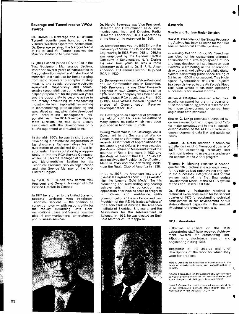
92
Beverage and Tunnel receive VWOA awards
Dr. Harold H. Beverage and G. William Tunnell recently were honored by the Veteran Wireless Operators Association. Dr. Beverage received the Marconi Medal of Honor and Mr. Tunnell received the Marconi Medal of Achievement.
G. (Bill) Tunnell joined RCA in 1940 in the Test Equipment Maintenance Section, where for several years he participated in the construction, repair and installation of extensive test facilities for items ranging from radio receivers to complex military radar, tv and special-purpose electronic equipment. Supervisory and adminstrative responsibilities during this period helped prepare him for the post-war years and the opportunity to become active in the rapidly developing tv broadcasting industry. He held responsibilities relating to merchandising, product planning and specialized selling, which later developed into product-line management responsibilities in the RCA Broadcast Equipment Division. He was quite closely associated with the development of tv studio equipment and related items.
In the mid-1950's, he spent a short period developing a nationwide organization of Manufacturer's Representatives for the distribution of specialized line of test instruments. This was cut short by an opportunity to join the RCA Service Company, where he became Manager of the Sales and Merchandising Section for the Technical Products Service organization and later Service Manager of the MidEastern Region.
In 1968, Mr. Tunnell was named Vice President and General Manager of RCA Service Division in Canada.
In 1971 he returned to the United States to become Division Vice President, Technical Services - the position he currently holds - with responsibility for the rapidly expanding Data Communications Lease and Service business plus rf communications, entertainment and business services.
Dr. Harold Beverage was Vice President, Research and Development, RCA Communications, Inc., and Director, Radio Research Laboratory, RCA Laboratories at the time of his retirement in 1958.
Dr. Beverage received the BSEE from the University of Maine in 1915 and the PhD in Engineering in 1938. From 1915 to 1916, he was employed by the General Electric Company in Schenectady, N. Y. During the next four years he was a radio laboratory assistant to Dr. E. F. W. Alexanderson, at General Electric. He joined RCA in 1920.
Dr. Beverage was elected a Vice-President of RCA Communications in December, 1940. Previously he was Chief Research Engineer of RCA Communications since 1929, when the company was formed as a wholly-owned RCA subsidiary. From 1920 to 1929, he served as Research Engineer in charge of Communication Receiver Development for RCA.
Dr. Beverage holds a number of patents in the field of radio. He is also the author of many papers on radio which have been published in technical journals.
During World War II, Dr. Beverage was a Consultant to the Secretary of War on Communications Problems, for which he received a Certificate of Appreciation from the Chief Signal Officer. He was awarded the Morris Liebmann Memorial Prize of the Institute of Radio Engineers in 1923 and the Medal of Honor of the I. R.E. in 1945. He also received the President's Certificate of Merit in 1948 and the Armstrong Medal from the Radio Club of America in 1938.
In June, 1957, the American Institute of Electrical Engineers (now IEEE) awarded him the Lamme Gold Medal "for his pioneering and outstanding engineering achievements in the conception and application of principles basic to progress in national and world-wide radio communications." He is a Fellow arid past President of the IRE. He is also a Fellow of the Radio Club of America, the American Institute of Electrical Engineers, and the Association for the Advancement of Science. In 1955, he was elected an Eminent Member of Eta Kappa Nu.
Awards
Missile and Surface Radar Division
David D. Freedman, of the Signal Process- ... ing Activity has been selected for the 1973 Annual Technical Excellence Award.
In winning this top honor, Mr. Freedman was cited for his outstanding technical achievements in ultra-high-speed circuitry and logic development applicable to radar systems, culminating in the conception, development, and delivery of a fully digital • system performing pulse-space-timing of 2.3 in. or 1/2560 microsecond. This HighSpeed Synchronizer (HISYNC) system has been delivered to the Air Force's Floyd Site radar where it has been operating successfully for several months.
James J. Campbell received a technical • excellence award for the third quarter of 1973 for outstanding effort in research and technique development to combat lowangle multi path problems.
Steven C. Lange received a technical excellence award for the third quarter of 1973 for major contributions to the successful demonstration of the AEGIS missile midcourse command data link and guidance policy.
Samuel D. Gross received a technical excellence award for the second quarter of 1973 for outstanding creativity and technical leadership in systems engineering aspects of the AFAR program.
Thomas H. Mehling received a second quarter 1973 technical excellence award for his role as lead radar system engineer in the successful integration and formal system tests of the first Engineering Development Model of the AEGIS system •. at the Land Based Test Site.
Dr. Ralph J. Pschunder received a technical excellence award for the second quarter of 1973 for outstanding technical achievement in his development of full state-of-the-art capability in the area of structural and dynamic analysis.
RCA Laboratories
Fifty-two scientists on the RCA Laboratories staff have received Achievement Awards for outstanding contributions to electronics research and .. engineering during 1973.
Recipients of the awards and brief descriptions of the work for which they were honored are:
Aline L. Akselrad for fundamental contributions to the fields of uniaxial anisotropy and magneto-optics in garnets.
Francis J. Campbell for development of a user-oriented computer program that takes into account the effects of space charge in calculating electron trajectories.
David E. Carlson for contributions to the understanding of the relationship between ionic motion and the modification of the properties of glasses.
..
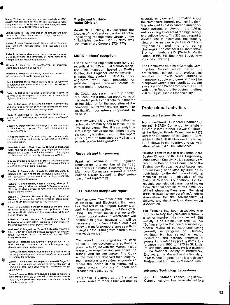
•
••
•
..
Sheng T. Hsu for measurement and analysis of SOS devices and application of noise theory to provide a more complete model of noise behavior and voltage current characteristics of MOS/SOS structures.
James Kane for the preparation of transparent high conductivity films by chemical vapor deposition of organometallic compounds.
Joseph D. Knox for advances in the fabrication of rugged and efficient acousta-optic and aCQusto-electric devices.
Peter A. Levine for development of innovative measurement techniques and invention of novel circuits for charge coupled device applications.
Steven A. Lipp for the development of improved cathodoluminescent phosphors.
Richard E. Novak for advancing methods of preparation of highly perfect single crystal garnets.
David Redfield for research leading to a fundamental understanding of the optical and transport properties of disordered solids.
Roger E. Schell for innovative mechanical design of devices used to prepare and characterize materials at high and low temperatures.
Hans G. Schwarz for outstanding effort in conceiving and analyzing a variety of new configurations for twoway broadband communications systems.
Frank V. Shallcross for the design and fabrication of silicon solid state image sensors and signal pprocessing devices.
Joseph A. Weisbecker for the design of a new computer architecture appropriate for mass production of microprocessors.
J. Rogers Woolston for developing computer methods, via time sharing, particularly in the area of materials characterization.
Jeremiah Y. Avins, Mario LaValva, Robert M. Rast, Juri Tulls, and Charles M. Wine for a team effort on the conception, design, and implementation of a highly flexible advanced community information system.
Guy W. Beakley and Warren H. Moles for a team effort leading to a better understanding of systems factors affecting color television reliability.
Charles J. Busanovich, Lincoln E. Ekstrom, John T. Fischer, and Robert M. Moore for a team effort leading to the successful development of a high-sensitivity cadmium selenide vidicon.
Richard F. Chamberlain, Yuan S. Chiang, George A. Swartz, Cheng P. Wen, and Albert F. Young for a team effort in the development of high efficiency low noise millimeterwave diodes.
Donald J. Channin, Michael T. Duffy, and Jacob M. Hammer for a team effort in the growth and fabrication of a high speed zinc oxide waveguide modulator.
Robert B. Comizzoli, Kenneth W. Hang and Werner Kern for a team effort in the synthesis and application of lead and borosilicate glasses in the passivation of silicon device structures.
Robert V. D'Aiello, Norman Goldsmith, and Paul H. Robinson for a team effort leading to improvements in the processing of silicon power devices
Andrew G. F. Dingwall and Edward C. Douglasfora team llffort in the development and application of ion implantation techniques in the fabrication of improved MOS integrated circuits.
David W. Fairbanks and Manvin A. Leedom for a team effort leading to advances in the technology of high density recording mechanisms.
Harry A. Freedman and Arthur Kalman for a team effort in the design, development. application of new commercial minicomputer software.
Gerald D. Held, Allen J. Korenjak, and Alfred H. Teger for a team effort in research leading to the development of hierarchial data base structures for electronic design applications.
Fumio Okamoto, Minoru Toda, and Solitior Tosima for a team effort in the field of acoustic surface-wave devices including temperature compensated and electronically tunable delay devices.
Missile and Surface Radar Division
Merrill W. Buckley, Jr., accepted the Chapter of the Year Award on behalf of the Engineering Management Group of the Philadelphia Section. Mr. Buckley was Chairman of the Group (1972-1973).
MSRD authors' reception
Over a hundred engineers were honored recently at MSRD's annual authors' reception. This reception, hosted by Dudley Cottier, Chief Engineer, was the seventh in a series that started in 1966 to honor engineers who have presented or published papers, received patents, or earned doctoral degrees.
Mr. Cottier addressed the group briefly: "You can't put a price tag on -the value of this kind of professional activity, either for an individual or for the reputation of the company. I won't even try. But I do want to say that it's important-very important-to all of us.
"In many ways it is the only yardstick the technical community has to measure the level of our capabilities. It is certainly true that a large part of our reputation around the country is a direct result of the papers you've given or published as well as the patents you've been granted."
Research and Engineering
Frank W. Widmann, Staff Engineer, Engineering is a member of the IEEE Manpower Committee. Recently, the 1973 Manpower Committee released a report entitled Career Out/ook in Engineering (described separately).
IEEE releases manpower report
The Manpower Committee of the Institute of Electrical and Electronics Engineers has released its 1973 report, Career Outlook in Engineering (Regions 1 through 6, USA). The report states that generally "career opportunities in electronics will continue to grow [however] ... it will be necessary to remain flexible and ever ready to transferto another area as activity changes in focus and grows in turn to meet market demands."
The report urges engineers to keep abreast of new developments so that it is possible to adjust with the market. It also warns of over-specializing your education during your college career. The Committee members observed that "employment problems are seldom encountered where the individual has maintained a regular program of study to update and broaden his background."
This book is planned as the first of an annual series of reports that will provide
accurate employment information about the electrical/electronic engineering field. It is intended to aid in career planning for those currently employed in the field as wei I as aiding students at the high school and college levels. The 225 page report is divided into four sections: the industry picture; the manpower picture; careers in engineering; and the engineering challenges. The cost for IEEE members is $10; non members $15. [Write to Martin Gitten, IEEE, 345 East 47th Street, New York, N.Y., 10017.]
The Committee studied a Carnegie Commission Report which called on professional schools and professional societies to provide careful studies of manpower supply and demand. "We [the Manpower Committee] heartily agree, and sincerely hope these activities of IEEE, of which this Report is the beginning effort, will fulfill just such a responsibility."
Professional activities
Aerospace Systems Division
Norm Laschever is General Chairman of the 1974 NEREM Convention to be held in Boston in late October. He was Chairman of the Special Events Committee in 1972 and Vice Chairman of the General Committee in 1973. NEREM is one of the largest IEEE shows in the country, and last year attracted almost 10,000 attendees.
Newton Teixeira is a past chairman of the Boston Chapter of the IEEE Engineering Management Society. He is a secretary pro tem of the Boston Area Committee on the Technology Forecasting and Assessment project being conducted by IEEE as its contribution to the definition of national technical goals (an objective of the National Science Foundation). He has recently been elected a member of the Ad Com (National Administrative Committee) of the Engineering Management Society of IEEE. He is also a memberofthe American Association for the Advancement of Science and the American Management Association.
Pat Toscano has been associated with IEEE for twenty-five years and is currently a senior member. His most recent IEEE activity is as Colloquium organizer for "Software for the Engineer": a six-session tutorial review of software engineering currently in progress on Thursday evenings. He has served as author, moderator, and session chiarman at several Automated Support Systems Conferences from 1966 to 1973 in St. Louis, Philadelphia, and Dallas. He is a member of the National Society of Professional Engineers, the Massachusetts Society of Professional Engineers and is a registered Professional Engineer in Massachusetts.
Advanced Technology Laboratories
John E. Friedman, Leader, Engineering Communications, has been elected to a
93
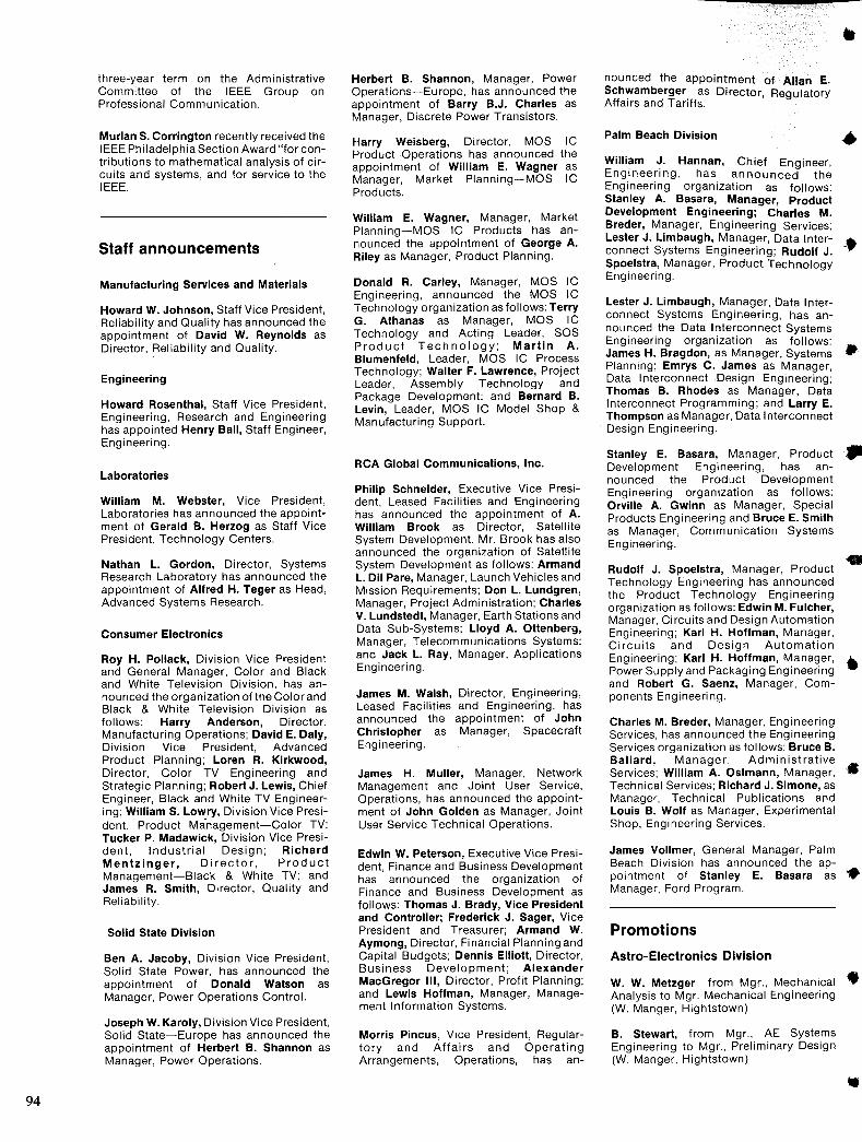
94
three-year term on the Administrative Committee of the IEEE Group on Professional Communication.
Murlan S. Corrington recently received the I EEE Ph iladelphia Section Award "for contributions to mathematical analysis of circuits and systems, and for service to the IEEE.
Staff announcements
Manufacturing Services and Materials
Howard W. Johnson, Staff Vice President, Reliability and Quality has announced the appointment of David W. Reynolds as Director, Reliability and Quality.
Engineering
Howard Rosenthal, Staff Vice President, Engineering, Research and Engineering has appointed Henry Ball, Staff Engineer, Engineering.
Laboratories
William M. Webster, Vice President, Laboratories has announced the appointment of Gerald B. Herzog as Staff Vice President, Technology Centers.
Nathan L. Gordon, Director, Systems Research Laboratory has announced the appointment of Alfred H. Teger as Head, Advanced Systems Research.
Consumer Electronics
Roy H. Pollack, Division Vice President and General Manager, Color and Black and White Television Division, has announced the organization of the Color and Black & White Television Division as follows: Harry Anderson, Director, Manufacturing Operations; David E. Daly, Division Vice President, Advanced Product Planning; Loren R. Kirkwood, Director, Color TV Engineering and Strategic Planning; Robert J. Lewis, Chief Engineer, Black and White TV Engineering; William S. Lowry, Division Vice President, Product Ma-nagement-Color TV: Tucker P. Madawick, Division Vice President, Industrial Design; Richard Mentzinger, Director, Product Management-Black & White TV; and James R. Smith, Director, Quality and Reliability.
Solid State Division
Ben A. Jacoby, Division Vice President, Solid State Power, has announced the appointment of Donald Watson as Manager, Power Operations Control.
Joseph W. Karoly, Division Vice President, Solid State-Europe has announced the appointment of Herbert B. Shannon as Manager, Power Operations.
Herbert B. Shannon, Manager, Power Operations-Europe, has announced the appointment of Barry B.J. Charles as Manager, Discrete Power Transistors.
Harry Weisberg, Director, MOS IC Product Operations has announced the appointment of William E. Wagner as Manager, Market Planning-MOS IC Products.
William E. Wagner, Manager, Market Planning-MOS IC Products has announced the appointment of George A. Riley as Manager, Product Planning.
Donald R. Carley, Manager, MOS IC Engineering, announced the MOS IC Technology organization as follows: Terry G. Athanas as Manager, MOS IC Technology and Acting Leader, SOS Product Technology; Martin A. Blumenfeld, Leader, MOS IC Process Technology; Walter F. Lawrence, Project Leader, Assembly Technology and Package Development; and Bernard B. Levin, Leader, MOS IC Model Shop & Manufacturing Support.
RCA Global Communications, Inc.
Philip Schneider, Executive Vice President, Leased Facilities and Engineering has announced the appointment of A. William Brook as Director, Satellite System Development. Mr. Brook has also announced the organization of Satellite System Development as follows: Armand L. Oil Pare, Manager, Launch Vehicles and Mission Requirements; Don L. Lundgren, Manager, Project Administration; Charles V. Lundstedt, Manager, Earth Stations and Data Sub-Systems; Lloyd A. Ollenberg, Manager, Telecommunications Systems; and Jack L. Ray, Manager, Applications Engineering.
James M. Walsh, Director, Engineering, Leased Facilities and Engineering, has announced the appointment of John Christopher as Manager, Spacecraft Engineering.
James H. Muller, Manager, Network Management and Joint User Service, Operations, has announced the appointment of John Golden as Manager, Joint User Service Technical Operations.
Edwin W. Peterson, Executive Vice President, Finance and Business Development has announced the organization of Finance and Business Development as follows: Thomas J. Brady, Vice President and Controller; Frederick J. Sager, Vice President and Treasurer; Armand W. Aymong, Director, Financial Planning and Capital Budgets; Dennis Ellioll, Director, Business Development; Alexander MacGregor III, Director, Profit Planning; and Lewis Hoffman, Manager, Management Information Systems.
Morris Pincus, Vice President, Regulartory and Affairs and Operating Arrangements, Operations, has an-
nounced the appointment of Allan E. Schwamberger as Director, Regulatory Affairs and Tariffs.
Palm Beach Division
William J. Hannan, Chief Engineer, Engineering, has announced the Engineering organization as follows:
.. Stanley A. Basara, Manager, Product Development Engineering; Charles M. Breder, Manager, Engineering Services; Lester J. Limbaugh, Manager, Data Inter- .. connect Systems Engineering; Rudolf J. -.,.. Spoelstra, Manager, Product Technology Engineering.
Lester J. Limbaugh, Manager, Data Interconnect Systems Engineering, has announced the Data Interconnect Systems Engineering organization as follows: James H. Bragdon, as Manager, Systems It Planning; Emrys C. James as Manager, Data Interconnect Design Engineering; Thomas B. Rhodes as Manager, Data Interconnect Programming; and Larry E. Thompson as Manager, Data Interconnect Design Engineering.
Stanley E. Basara, Manager, Product Development Engineering, has announced the Product Development Engineering organization as follows: Orville A. Gwinn as Manager, Special Products Engineering and Bruce E. Smith as Manager, Communication Systems Engineering.
Rudolf J. Spoelstra, Manager, Product Technology Engineering has announced the Product Technology Engineering organization as follows: Edwin M. Fulcher, Manager, Circuits and Design Automation Engineering; Karl H. Hoffman, Manager, Circuits and Design Automation Engineering; Karl H. Hoffman, Manager, • Power Supply and Packaging Engineering and Robert G. Saenz, Manager, Components Engineering.
Charles M. Breder, Manager, Engineering Services, has announced the Engineering Services organization as follows: Bruce B. Ballard, Manager, Administrative Services; William A. Ostmann, Manager, .• Technical Services; Richard J. Simone, as Manager, Technical Publications and Louis B. Wolf as Manager, Experimental Shop, Engineering Services.
James Vollmer, General Manager, Palm Beach Division has announced the appointment of Stanley E. Basara as • Manager, Ford Program.
Promotions
Astro-Electronics Division
W. W. Metzger from Mgr., Mechanical • Analysis to Mgr. Mechanical Engineering (W. Manger, Hightstown)
B. Stewart, from Mgr., AE Systems Engineering to Mgr., Preliminary Design (W. Manger, Hightstown)
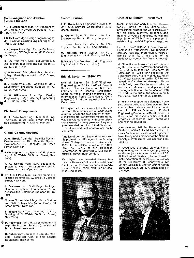
Electromagnetic and Aviation Systems Division
B. J. Fletcher from Mgr., "A" Program to ..... Mgr., Military Program Operations (F. C. W"Corey, Van Nuys)
J. R. Hall from Mgr., Design Engineering to Mgr., Position Locating Engineering (F. C. Corey, Van Nuys)
R. C. Hayes from Mgr., Design Engineering to Mgr., EW Engineering (F. C. Corey,
• Van Nuys)
H. Hite from Mgr., Electrical Develop. & Des. to Mgr., Electrical Engineering (F. C. Corey, Van Nuys)
W. MeRea from Adm., Govt. Prog. Services to Mgr., Govt. Systems Adm. (F. C. Corey,
• Van Nuys)
R. L. Reed from Ldr., Logistics to Mgr., Government Programs Support (F. C. Corey, Van Nuys)
J. W. Williamson from Mgr., Design Engineering to Mgr., Memory Engineering (F. C. Corey, Van Nuys)
Electronic Components
G. T. Rose from Engr., Manufacturing, Television Picture Tube to Mgr., Production Engineering (N. Meena, Marion)
Global Communications
A. W. Brook from Mgr., Satellite System Development to Dir., Satellite System Development (p. Schneider, 60 Broad Street, New York)
• J. Christopher Mgr., Spacecraft Engineering (J. M. Walsh, 60 Broad Street, New York)
A. C. Cowan from RCA Educational System to Mgr., Iran Operations (A. A. Avanessians, Iran Operations)
• Dr. A. Oil Pare Mgr., Launch Vehicle & Mission Reports (A. W. Brook, 60 Broad Street, New York)
J. Gleitman from Staff Engr., to Mgr., Computer Systems Engineering (A. A. Avanessians, Computer Engineering Projects)
• Charles V. Lundstedt Mgr., Earth Station and Data Subsystems (A. W. Brook, 60 Broad Street, New York)
F. Mieara from Tech. Illustrator to Ldr., Drafting (J. M. Walsh, 60 Broad Street, New York)
.. M. Rosenthal from Ldr., Documentation to Mgr., Engineering Services (J. Walsh, 60 Broad Street, New York)
•
R. Ruben from Engineer to Ldr., (D. Mandato, Technical Control and Special Equipment Engineering)
Record Division
J. E. Grein from Engineering Assoc. to Mgr., Mfg. Services Coordination (J. R. Mason, Indpls.)
J. Gunter from Sr. Membr. to Ldr., Engineering Staff (J. E. Lang, Indpls.)
J. Heller from Sr. Membr. to Ldr., Engineering Staff (J. E. Lang, Indpls.)
M. McNeely from Member to Ldr., Engineering Staff (J. R. Mason, Indpls.)
R. Nyman from Member to Ldr., Engineering Staff (J. R. Mason, Indpls.)
Eric M. Ley ton - 1916-1974
Eric M. Ley ton, 58, Staff' Engineer, Engineering, for RCA at the David Sarnoff Research Center in Princeton, N.J., died February 26 in Geneva, Switzerland, where he was attending a meeting of the International Radio Consultative Committee (CCIR) at the request of the State Department.
Mr. Ley ton, who was associated with RCA for more than twenty years, made major contributions to the development of television transmitters and tvtape recording. He was actively concerned with color television systems for many years and frequently represented both the United States and RCA at international conferences on tv standards.
A native of London, England, he received his professional EE degree from Faraday House College of London University in 1938. He joined RCA Laboratories in 1953 after six years at the Research Laboratories of Electrical & Musical Industries, Hayes, near London.
Mr. Ley ton was awarded twenty two patents. He was a Fellow of the Institute of Electrical and Electronics Engineers and a member of the British Institution .of Electrical Engineers .
Chester M. Sinnett - 1900-1974
Mack Sinnett died early this year. He was widely known for his distinguished professional engineering work at RCA and for his encouragement, guidance, and training of young engineers. He was the first Editor of TREND and a pioneer in establishing the RCA Engineer magazine.
He retired from RCA as Director, Product Engineering Professional Development, in January 1965 after more than 40 years of service with RCA and one of its predecessor companies (Westinghouse).
Mr. Sinnett went to work for the Engineering Department of the Westinghouse Electric and Manufacturing Company in Pittsbu rg h in 1924 after he received the BSEE from the University of Maine. When RCA Victor was organized in 1929, he was moved to Camden as Manager, Phono graph Design and Development. Later, he was named Manager, Loudspeaker and Phonograph Section. In connection with his work in the audio and acoustic field, Mr. Sinnett was granted 30 patents.
In 1945, he was appointed Manager, Home Instruments Advanced Development Section. He held this post until his appointment in 1959 as Director of Product Engineering Professional Development. In this position, his responsibilities included programs concerned with continuing engineering education.
A Fellow of the IEEE, Mr. Sinnett served as Chairman of the Philadelphia Section. He was a Registered Professional Engineer in New Jersey and a member of the National Society of Professional Engineers and Tau Beta Pi.
A recognized authority on creativity in engineering, Mr. Sinnett lectured widely on the subject within and outside of RCA. At the time of his death, he was Head of Instrumentation at the Pepper Laboratory of the University of Pennsylvania. Mr. Sinnett was also a Charter Member of the Electronic Club, an RCA organization in Camden.
95
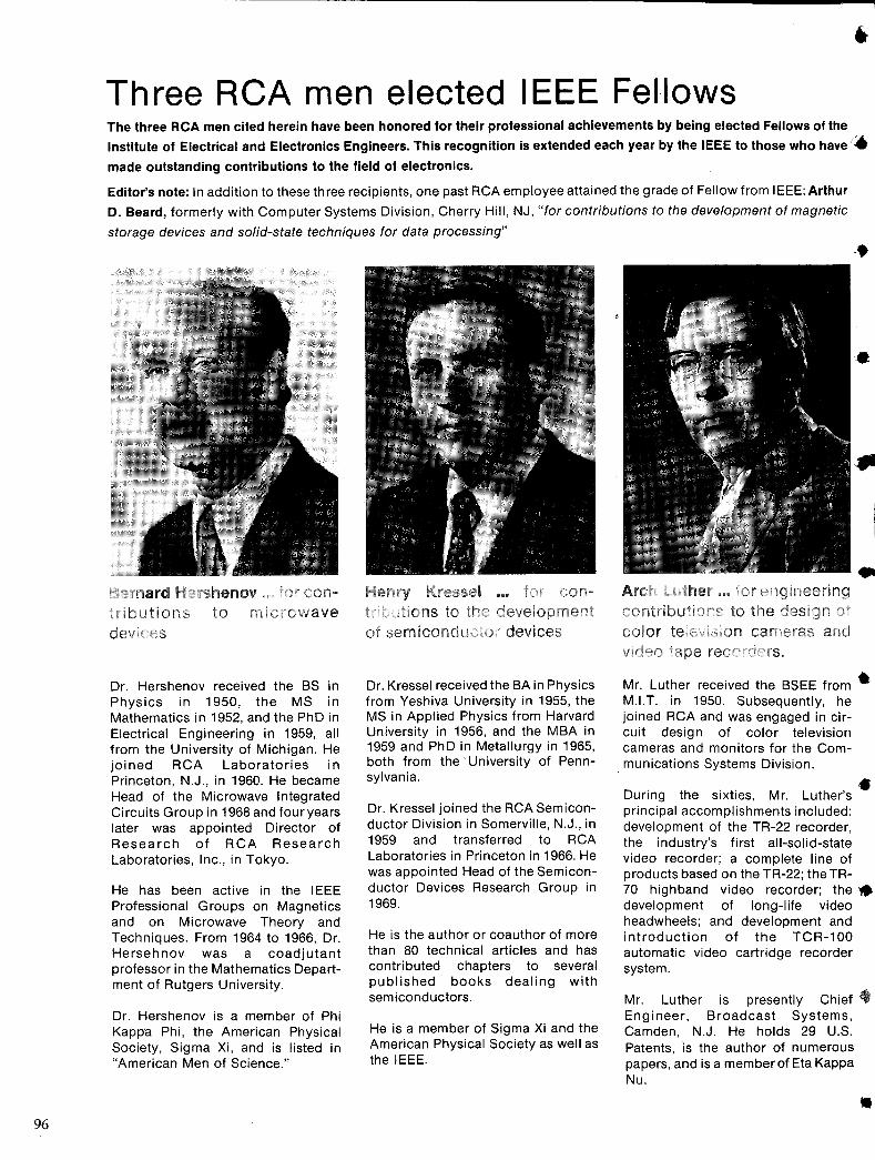
96
Three RCA men elected IEEE Fellows The three RCA men cited herein have been honored for their professional achievements by being elected Fellows of the
Institute of Electrical and Electronics Engineers. This recognition is extended each year by the IEEE to those who have.
made outstanding contributions to the field of electronics.
Editor's note: In addition to these three recipients, one past RCA employee attained the grade of Fellow from IEEE: Arthur
D. Beard, formerly with Computer Systems Division, Cherry Hill, NJ, "for contributions to the development of magnetic
storage devices and solid-state techniques for data processing"
Dr. Hershenov received the BS in Physics in 1950, the MS in Mathematics in 1952, and the PhD in Electrical Engineering in 1959, all from the University of Michigan. He joined RCA Laboratories in Princeton, N.J., in 1960. He became Head of the Microwave Integrated Circuits Group in 1968 and fouryears later was appointed Director of Research of RCA Research Laboratories, Inc., in Tokyo.
He has been active in the IEEE Professional Groups on Magnetics and on Microwave Theory and Techniques. From 1964 to 1966, Dr. Hersehnov was a coadjutant professor in the Mathematics Department of Rutgers University.
Dr. Hershenov is a member of Phi Kapp'a Phi, the American Physical Society, Sigma Xi, and is listed in "American Men of Science."
Dr. Kressel received the BA in Physics from Yeshiva University in 1955, the MS in Applied Physics from Harvard University in 1956, and the MBA in 1959 and PhD in Metallurgy in 1965, both from the' University of Pennsylvania.
Dr. Kressel joined the RCA Semiconductor Division in Somerville, N.J., in 1959 and transferred to RCA Laboratories in Princeton in 1966. He was appointed Head of the Semiconductor Devices Research Group in 1969.
He is the author or coauthor of more than 80 technical articles and has contributed chapters to several published books dealing with semiconductors.
He is a member of Sigma Xi and the American Physical Society as well as the IEEE.
••
Mr. Luther received the BSEE from • M.I.T. in 1950. Subsequently, he joined RCA and was engaged in circuit design of color television cameras and monitors for the Communications Systems Division.
D · th .. • unng e sixties, Mr. Luther's principal accomplishments included: development of the TR-22 recorder, the industry's first all-solid-state II
video recorder; a complete line of products based on the TR-22; the TR- I 70 highband video recorder; the. development of long-life video headwheels; and development and introduction of the TCR-100 automatic video cartridge recorder system.
Mr. Luther is presently Chief. Engineer, Broadcast Systems, Camden, N.J. He holds 29 U.S. Patents, is the author of numerous papers, and is a member of Eta Kappa Nu.
•
•
•
•
•
•
Aerospace Systems Division
Electromagnetic and Aviation Systems Division
Astro-Electronics Division
Missile & Surface Radar Division
Government Engineering
Government Plans and Systems Development
Communications Systems Division Broadcast Systems
Mobile Communications Systems Government Communications Systems
Palm Beach Division
Laboratories
Entertainment Tube Division
Industrial Tube Division
Solid State Division
Consumer Electronics
RCA Service Company
Parts and Accessories
The Editorial Representative in your group is the one you should contact in scheduling technical papers and announcements of your professional activities.
Engineering, Burlington, Mass.
Engineering, Van Nuys, Calif.
Aviation Equipment Engineering, Van Nuys, Calif.
Engineering, Princeton, N.J. Advanced Development and Research, Princeton, N.J.
Engineering, Moorestown, N.J.
Advanced Technology Laboratories, Camden, N.J. Advanced Technology Laboratories, Camden, N.J.
Central Engineering, Camden, N.J.
, Eng. Information and Communications, Camden, N.J.
Broadcast Systems Advanced Development, Camden, N.J.
Broadcast Systems Antenna Equip. Eng., Gibbsboro, N.J.
Advanced Development, Meadow Lands, Pa.
Palm Beach Gardens, Fla.
·Somerville, N.J. Solid State Technology Center, Somerville, N.J.
Chairman, Editorial Board, Harrison, N.J.
Receiving Tube Operations, Woodbridge, N.J. Television Picture Tube Operations, Marion, Ind.
Engineering, Lancaster, Pa.
Industrial Tube Operations, Lancaster, Pa. Solid State Product Development Engineering, Harrison, N.J
Chairman, Editorial Board, Somerville, N.J. Solid State Division, Somerville, N.J.
Solid State Division, Mountaintop, Pa. Power Transistors, Somerville, N.J.
Integrated Circuits, Somerville, N.J. Solid State Division, Findlay, Ohio
Chairman, Editorial Board, Indianapolis, Ind.
Audio Products Engineering, Indianapolis, Ind. Advanced Development, Indianapolis, Ind.
Black and White TV Engineering, Indianapolis, Ind. Color TV Engineering, Indianapolis, Ind. Engineering, RCA Taiwan Ltd., Taipei, Taiwan
Consumer Services Administration, Cherry Hill, N.J. Consumer Service Field Operations, Cherry Hill, N.J.
Technical Support, Cherry Hill, N.J.
Product Development Engineering, Deptford, N.J
RCA Global Communications, Inc., New York, N.Y. RCA Alaska Communications, Inc., Anchorage Alaska
Staff Eng .. Technical Development, New York. N.Y
Record Eng., Indianapolis, Ind.
International Planning, New York, N.Y Research & Eng. Montreal, Canada
Patent Plans and Services, Princeton, N.J
~Technical Publications Administrators (asterisked . above) are
responsible for review and approval of papers and presentations