Embed Size (px)
Citation preview
Executive Summary ............................................................................................................................................... ii
Project Management ...............................................................................................................................................1
Organization Chart ..................................................................................................................................................2
Hull Design and Structural Analysis .......................................................................................................................3
Development and Testing .................................................................................................................................. ...5
Construction ............................................................................................................................................................8
Project Schedule ....................................................................................................................................................10
Design Drawing ....................................................................................................................................................11
LIST OF FIGURESFigure 1: ForeverGlades Person-Hours ................................................................................................................. 1
Figure 2: Financial Allocation…………………………………………………………………………………….1
Figure 3: Transom Stern Flow Separation. ............................................................................................................ 3
Figure 4: Free Body Diagram for Men’s Sprint……... ......................................................................................... 4
Figure 5: Free Body Diagram for Lateral Analysis................................................................................................ 4
Figure 6: Iterative Process of Concrete Mix Design....................................................................................... 5
Figure 7: Third-Point Flexure Test on Composite Panel……………………………………………………........5
Figure 8: Neoprene Caps during Compression Test………………………………………………………………7
Figure 9: Cross Sections Supported and Bolted to Beam.......................................................... ………………….8
Figure 10: Structural Rib Form……………………… ........................................................................................ ..8
Figure 11: Initial Curing with Heated Soaker Hose……………………………………………………………….9
Figure 12: Aesthetic Alligator in Practice Canoe…………………………………………………………………9
LIST OF TABLESTable 1: ForeverGlades Concrete Properties ....................................................................................................... ii
Table 2: ForeverGlades Concrete Properties Compared to AcceleGator............................................................. 7
LIST OF APENDICESAppendix A: References…………. ....................................................................................................................A-1
Appendix B: Mixture Proportions…………...................................................................................................... B-1
Appendix C: Bill of Materials. ........................................................................................................................... C-1
Appendix D: Example Structural Calculation………………………………………………………………….D-1
Comprising the nation’s largest subtropical wetland, Everglades National Park provides sanctuary for thirty-six protected animal species across nearly 1.5 million grassy acres in south Florida. The natural,
pulsing surface water flow of the larger Everglades basin has been continuously disrupted due to development since the late 1800s. While it was human intervention that originally altered the flow
balance, today, a more systemic engineering mentality is employed to remedy past oversights. The Comprehensive Everglades Restoration Plan (CERP) guides the effort to protect and preserve the water resources of the Everglades. Located several hundred miles to the north in Gainesville, the University of Florida (UF) has created research and extension programs to address these pressing issues. The programs aim to enhance the quality of natural areas and improve the abundance and diversity of native species, while also meeting urban and agricultural water demands. As one of the most comprehensive and academically diverse public universities in the nation, UF serves more than 50,000 students annually with 16 colleges and more than 150 research centers and institutes (University of Florida 2014). Competing in one of the largest and most arduous ASCE student conferences in the United States, the UF Concrete Canoe Team has placed 1st
in the southeast region the last three years, accumulating finishes of 12th (AcceleGator, 2014), 3rd (ConquistaGator, 2013), and 5th (VindiGator, 2012) at the national level. The UF Team began its season by moving all production from a satellite facility to an on-campus research laboratory. The space proved to be effective for recruitment purposes, drawing in a larger, younger team than in previous years. With youth came inexperience, prompting captains, with the help of team veterans, to draft best management practices to guide future teams. Proximity to numerous active research projects allowed the team to better utilize university resources. With the move, many construction and mix design techniques were improved in order to meet space constraints and ensure safety of the team and surrounding personnel. This year, the paddling team was committed to kneeling in all five races to maximize its competitive advantage. Accordingly, a hull design was developed to enhance paddler stability without impeding maneuverability. The concrete mix design focused on improving tensile strengths while incorporating new materials for an even lighter mix. In an effort to improve upon previous teams’ final product scores, a schedule was created which
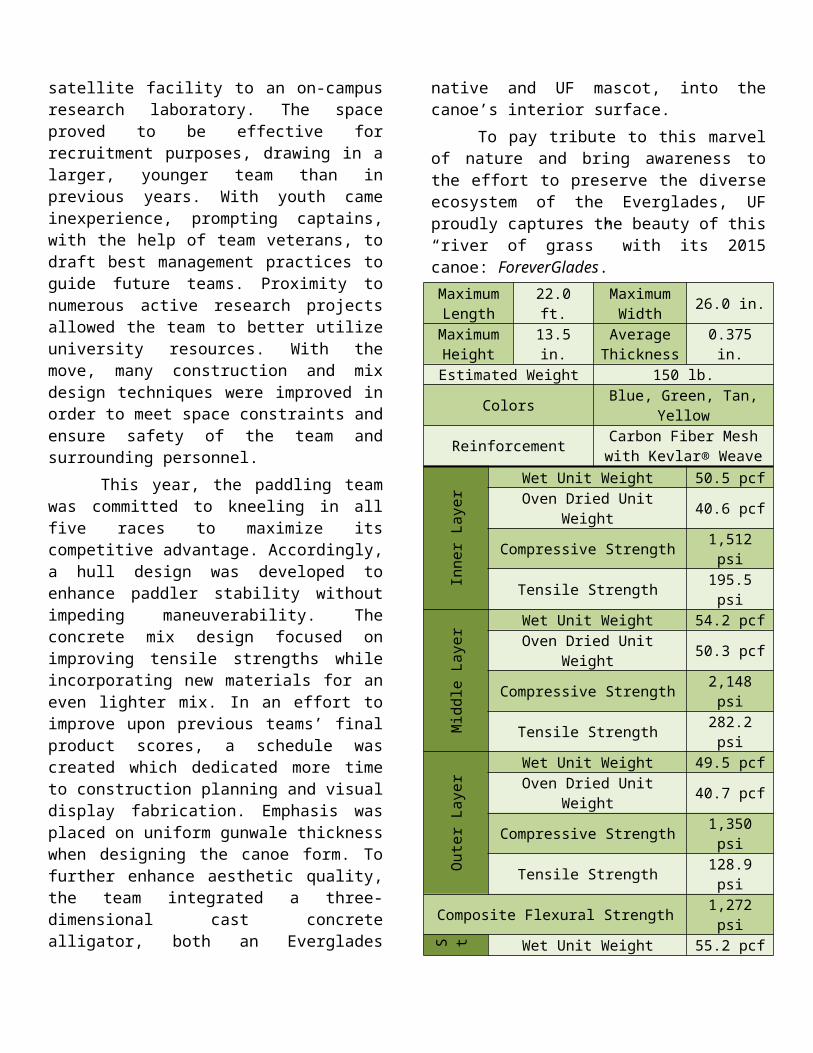
dedicated more time to construction planning and visual display fabrication. Emphasis was placed on uniform gunwale thickness when designing the canoe form. To further enhance aesthetic quality, the team integrated a three-dimensional cast concrete alligator, both an Everglades native and UF mascot, into the canoe’s interior surface. To pay tribute to this marvel of nature and bring awareness to the effort to preserve the diverse ecosystem of the Everglades, UF proudly captures the beauty of this “river of grass” with its 2015 canoe: ForeverGlades.Maximum
Length 22.0 ft. MaximumWidth 26.0 in.
Maximum Height 13.5 in. Average
Thickness 0.375 in.
Estimated Weight 150 lb.Colors Blue, Green, Tan, Yellow
Reinforcement Carbon Fiber Mesh with Kevlar® Weave
Inne
r La
yer Wet Unit Weight 50.5 pcf
Oven Dried Unit Weight 40.6 pcfCompressive Strength 1,512 psi
Tensile Strength 195.5 psi
Mid
dle
Laye
r Wet Unit Weight 54.2 pcfOven Dried Unit Weight 50.3 pcf
Compressive Strength 2,148 psiTensile Strength 282.2 psi
Out
er
Laye
r Wet Unit Weight 49.5 pcfOven Dried Unit Weight 40.7 pcf
Compressive Strength 1,350 psiTensile Strength 128.9 psi
Composite Flexural Strength 1,272 psi
Stru
ctur
al R
ibs
Wet Unit Weight 55.2 pcfOven Dried Unit Weight 52.7 pcf
Compressive Strength 1,666 psiTensile Strength 270.9
Aes
thet
ic
Past
e
Wet Unit Weight 120.0 pcfOven Dried Unit Weight 105.8 pcf
Compressive Strength N/ATensile Strength N/A
A single head captain, acting as the project manager, took on the tasks of recruitment, budgeting, scheduling, and delegating for the ForeverGlades team. To round out the team, five captains were selected as project engineers to lead the concrete mix design, hull design/structural
Table 1: ForeverGlade
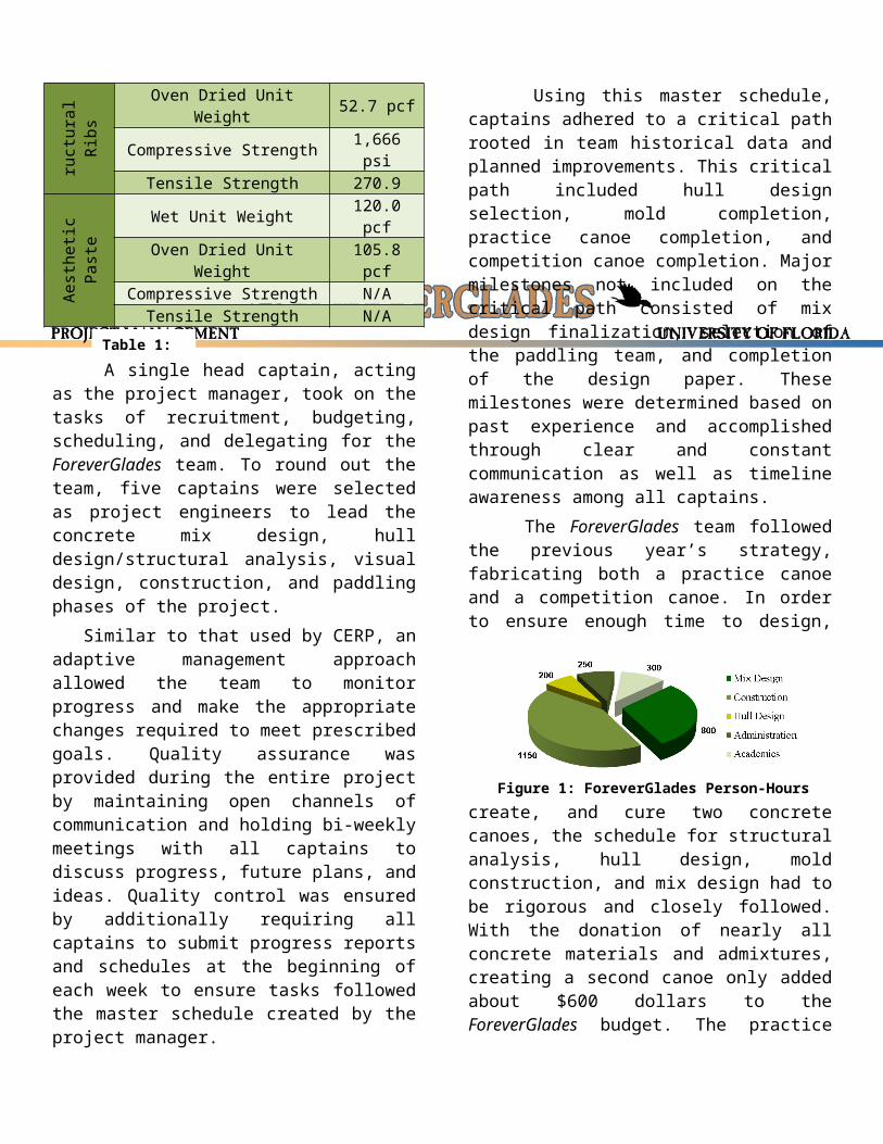
analysis, visual design, construction, and paddling phases of the project. Similar to that used by CERP, an adaptive management approach allowed the team to monitor progress and make the appropriate changes required to meet prescribed goals. Quality assurance was provided during the entire project by maintaining open channels of communication and holding bi-weekly meetings with all captains to discuss progress, future plans, and ideas. Quality control was ensured by additionally requiring all captains to submit progress reports and schedules at the beginning of each week to ensure tasks followed the master schedule created by the project manager. Using this master schedule, captains adhered to a critical path rooted in team historical data and planned improvements. This critical path included hull design selection, mold completion, practice canoe completion, and competition canoe completion. Major milestones not included on the critical path consisted of mix design finalization, selection of the paddling team, and completion of the design paper. These milestones were determined based on past experience and accomplished through clear and constant communication as well as timeline awareness among all captains. The ForeverGlades team followed the previous year’s strategy, fabricating both a practice canoe and a competition canoe. In order to ensure enough time to design, create, and cure two concrete canoes, the schedule for structural analysis, hull design, mold construction, and mix design had to be rigorous and closely followed. With the donation of nearly all concrete materials and admixtures, creating a second canoe only added about $600 dollars to the ForeverGlades budget. The practice canoe allowed 18 newly-recruited members to become familiar with the precision required during the placement process. Additionally, the team had the opportunity to test new construction and mix design techniques to mitigate errors before the competition canoe placement one month later. The team also benefitted by paddling in the chosen hull design during the months leading up to the competition. Efficiency in time management and the donation of a second shotcrete gun allowed for a reduction of 75 person-hours from the placement of
the practice canoe to the competition canoe. Overall, the team put in over 2,300 person-hours designing, testing, and constructing ForeverGlades
(Figure 1).
Before being admitted into the lab, each team member was required to attend an informative, concrete canoe-specific safety training session, as well as complete 12 hours of online safety courses. After this initial session, the team was instructed on each tool used in the lab to ensure the utmost level of safety at all times. Those working with concrete materials were required to read material safety data sheets for all substances used, and personal protective equipment was required and supplied in all areas of the lab. The team worked hand-in-hand with the laboratory staff to guarantee appropriate handling of tools and materials at all times.
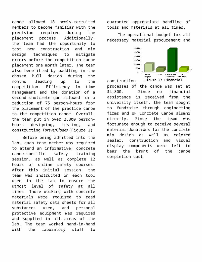
The operational budget for all necessary material procurement and construction processes of the canoe was set at $4,800. Since no financial assistance is received from the university itself, the team sought to fundraise through engineering firms and UF Concrete Canoe alumni directly. Since the team was fortunate enough to receive several material donations for the concrete mix design as well as colored sealer, construction and visual display components were left to bear the brunt of the canoe completion cost.
Figure 1: ForeverGlades Person-Hours
Figure 2: Financial Allocation
The ForeverGlades hull design team drew upon well documented and successful hull forms from past years to maintain a tradition of excellence in design. Obtaining feedback from last year’s paddlers and using AcceleGator (2014) as a baseline, the team focused on refining the hull for improved race performance. Design goals were geared toward balancing straight-line speed and maneuverability, while improving stability in order to accommodate the kneeling paddling style.
The design team sought to increase straight line speed by reducing the hull’s wave-making resistance. This can be achieved by maximizing waterline length; however, with the canoe length constrained at 22 ft. due to the rules, other parameters had to be altered (NCCC 2015). The bow rocker was decreased from 5.5 in. to 4 in. This decrease in curvature reduced maneuverability which, in turn, increased tracking. To compensate, the rocker curvature was maintained along the hull bottom, providing less lateral resistance and promoting boundary layer cohesion. This combination maintained sufficient maneuverability while minimizing wave-making resistance (Winters 2006).
The continued use of a transom stern this year also helped to maximize waterline length. This truncation allows flow to continue as if the canoe actually extended out to a point as shown in Figure 3. This decrease in form resistance results in an increased effective waterline length. Proper separation was achieved through correct sizing of the truncation by maintaining the Froude number above 2.0 (Maki et al. 2005).
The ForeverGlades hull profile was flattened slightly, which enhanced the initial stability of the canoe (Gullion 1994). The need for improved stability was expressed by paddlers in order to more comfortably and effectively deliver power while
kneeling. Wave-making resistance tends to increase with a larger surface area; however, with a flatter bottom, the sanding process can be carried out more accurately, giving the hull a smoother finish and reducing friction drag when compared with AcceleGator (2014). A 15 degree raked bow, added for aesthetic purposes, decreased the amount of deadwood in the bow, further reducing wetted surface area and friction drag. From previous years’ scale model test data, this bow angle was determined to be the most efficient (Gladigator 2007).
Hulls were designed using FREE!ship (Timoshenko 2013), an open-source hull design software. The designs were then imported into Mitchlet (Lazauskas 2013), a free computational fluid dynamics program, to accurately compare wave resistances. Resistances were analyzed for hull speeds ranging from 1 to 6 knots, the estimated maximum speed during the co-ed sprint race. From these results, 4 designs were chosen to be tested for straight-line speed and maneuverability. Scale models at 1:6 size were milled using a computer numerical controlled (CNC) machine at an on-campus fabrication center. This scale was chosen to best maintain model similitude, matching Froude numbers while remaining in an acceptable range of Reynolds number.
Based on design criteria and scale model test performance, a final hull was selected with a shallow arch bottom, 22-ft. length, 26-in. beam, and 2-in. transom stern. ForeverGlades improves upon last year’s straight-line speed while maintaining comparable turning ability and meeting all design goals.
Structural analysis was performed with the purpose of determining the critical tensile and compressive strengths required for the hull to undergo various predetermined loading cases. The loading conditions considered included the men’s sprint, co-ed sprint, and the de-molding, transportation, and display of the canoe. Analysis was performed longitudinally along the length of the canoe and laterally along the beam of the hull to obtain critical values. For each orientation of analysis, the canoe was assumed to be a two-dimensional beam.
Figure 3: Transom Stern Flow Separation
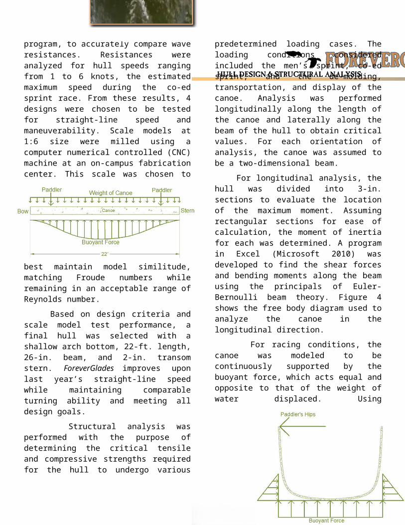
For longitudinal analysis, the hull was divided into 3-in. sections to evaluate the location of the maximum moment. Assuming rectangular sections for ease of calculation, the moment of inertia for each was determined. A program in Excel (Microsoft 2010) was developed to find the shear forces and bending moments along the beam using the principals of Euler-Bernoulli beam theory. Figure 4 shows the free body diagram used to analyze the canoe in the longitudinal direction.
For racing conditions, the canoe was modeled to be continuously supported by the buoyant force, which acts equal and opposite to that of the weight of water displaced. Using displacements for specific loading cases, the draft was determined from the program FREE!ship (Timoshenko 2013). From the draft, the submerged volume of each section was calculated and multiplied by specific weight of water to obtain the buoyant force. The weight of the canoe, assumed from AcceleGator (2014) as 160 lb., was uniformly distributed over its length. Point loads of 200 lb. and 170 lb. represented the male and female paddlers, respectively. These values included a 25% increase to account for dynamic load amplification during the races (Paradis and Gendron 2006). The loads were placed 4 ft. and 18 ft. from the bow, simulating the men’s sprint. Two female loads were added at 8 ft. and 14 ft. for the co-ed sprint. Analysis of the display scenario resulted in the determination of the optimal placement of two stands at 4 ft. and 17 ft. from the bow.
The critical loading case was found to occur during the men’s sprint, with a maximum negative bending moment of 9,464 in.-lb. located 11 ft. from the bow. Using the location of the section’s neutral
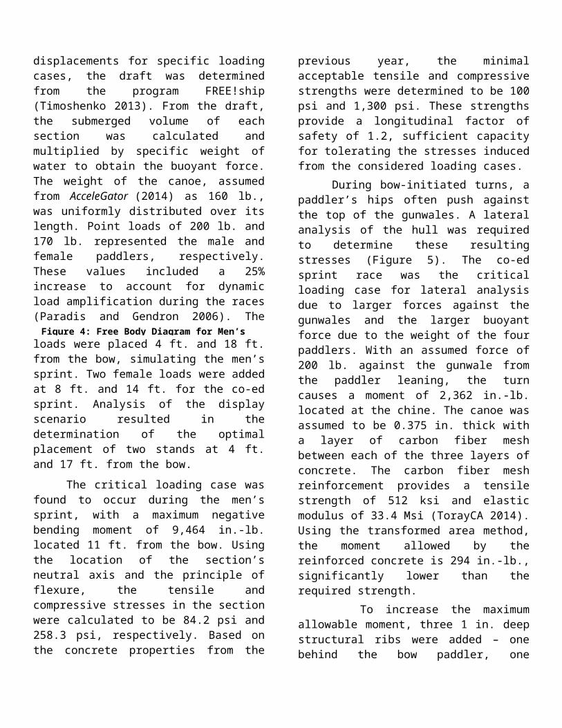
axis and the principle of flexure, the tensile and compressive stresses in the section were calculated to be 84.2 psi and 258.3 psi, respectively. Based on the concrete properties from the previous year, the minimal acceptable tensile and compressive strengths were determined to be 100 psi and 1,300 psi. These strengths provide a longitudinal factor of safety of 1.2, sufficient capacity for tolerating the stresses induced from the considered loading cases. During bow-initiated turns, a paddler’s hips often push against the top of the gunwales. A lateral analysis of the hull was required to determine these resulting stresses (Figure 5). The co-ed sprint race was the critical loading case for lateral analysis due to larger forces against the gunwales and the larger buoyant force due to the weight of the four paddlers. With an assumed force of 200 lb. against the gunwale from the paddler leaning, the turn causes a moment of 2,362 in.-lb. located at the chine. The canoe was assumed to be 0.375 in. thick with a layer of carbon fiber mesh between each of the three layers of concrete. The carbon fiber mesh reinforcement provides a tensile strength of 512 ksi and elastic modulus of 33.4 Msi (TorayCA 2014). Using the transformed area method, the moment
allowed by the reinforced concrete is 294 in.-lb., significantly lower than the required strength. To increase the maximum allowable moment, three 1 in. deep structural ribs were added – one behind the bow paddler, one amidship, and one toward the stern – providing enough room for the aftmost paddler. The added ribs raised the
Figure 4: Free Body Diagram for Men’s Sprint
Figure 5: Free Body Diagram for Lateral Analysis
maximum allowable moment to 6,440 in.-lb., which increased the overall lateral factor of safety to 2.73.
As the 2014-2015 campaign began, the mix design team resolved to further build upon the success achieved in the previous year. To this end, the ForeverGlades team looked to vastly improve the compressive, tensile, and flexural strengths of the canoe, simultaneously re-capturing the low unit weights and smooth outer finishes of years past. In doing so, the team was able to create mixes which surpassed calculated structural requirements by a wide margin.
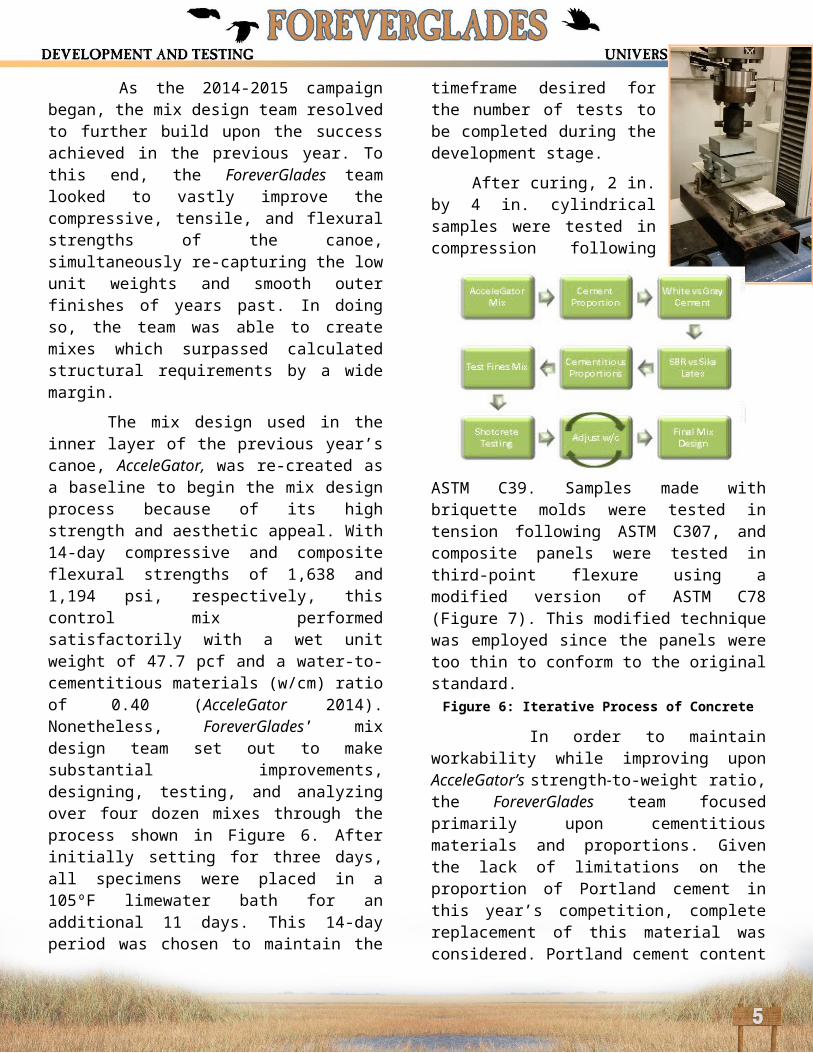
The mix design used in the inner layer of the previous year’s canoe, AcceleGator, was re-created as a baseline to begin the mix design process because of its high strength and aesthetic appeal. With 14-day compressive and composite flexural strengths of 1,638 and 1,194 psi, respectively, this control mix performed satisfactorily with a wet unit weight of 47.7 pcf and a water-to-cementitious materials (w/cm) ratio of 0.40 (AcceleGator 2014). Nonetheless, ForeverGlades’ mix design team set out to make substantial improvements, designing, testing, and analyzing over four dozen mixes through the process shown in Figure 6. After initially setting for three days, all specimens were placed in a 105ºF limewater bath for an additional 11 days. This 14-day period was chosen to maintain the timeframe desired for the number of tests to be completed during the development stage.
After curing, 2 in. by 4 in. cylindrical samples were tested in compression following ASTM C39. Samples made with briquette molds were tested in tension following ASTM C307, and composite panels were tested in third-point flexure using a modified version of ASTM C78 (Figure 7). This modified technique was employed since the panels were too thin to conform to the original standard.
In order to maintain workability while improving upon AcceleGator’s strength-to-weight ratio, the ForeverGlades team focused primarily upon cementitious materials and proportions. Given the lack of limitations on the proportion of Portland cement in this year’s competition, complete replacement of this material was considered. Portland cement content was lowered in steady increments until it constituted zero percent of the cementitious material. However, once the proportion of Portland cement fell below 25% of the mix’s total cementitious material, strength and bonding fell precipitously. Decreasing the amount of Portland cement allowed for an increase in the amount of ground blast furnace slag. Ground blast furnace slag’s propensity for strength gains under high curing temperatures contributed to increases perceived during testing (Ferraro 2009).
Notably, two new cementitious materials were utilized for the 2014-2015 season: VCAS™ 160 and white Portland cement. Often considered very similar to gray Portland cement, white Portland cement was a novel addition for ForeverGlades’ mix team due to its light color. Its high potential for reactivity with pozzolans, which stems from its low ferrite content, was another reason for its use (Lubeck et al. 2011). VCAS™ 160, a newly-considered recycled glass powder, was tested for its ability to lower water demand. This property allows for the pozzolanic material to be used in concrete with low w/cm ratios (Hossain et al. 2008). Ultimately, VCAS™ 160 found favor over two alternatives, Class F fly ash and metakaolin. It was extensively tested in several variations, replacing fly ash and/or metakaolin to varying extents. The highest compressive strength resulted from a complete replacement of metakaolin and fly ash with VCAS™ 160. Furthermore, its white color made it an attractive candidate for the
Figure 6: Iterative Process of Concrete Mix Design
ForeverGlades team, as neither the off-white metakaolin nor the gray fly ash could foster lighter-tinted mixes; this conformed to the team’s aesthetic goal of creating a lighter-colored canoe for sealing purposes. Of significant concern for the AcceleGator team was the continued propagation of cracks on the hull, an issue which arose late in the season. In order to increase tensile strength, the ForeverGlades team employed basalt fibers. Basalt fibers are lightweight fibers made from molten rock with a tenacity higher than that of steel. They improve flexural strength, do not absorb water, and have the same coefficient of thermal expansion as concrete (Cheng 2014). Although basalt fibers have a lower clumping risk when mixed, they still leave the shotcrete gun vulnerable to clogging. To offset this risk and remain in accordance with ASTM C1116, the well-staffed ForeverGlades team dedicated hundreds of hours to the separation of fibers from one another. Several methods, namely the use of compressed air, were tested to increase the efficiency of separating fibers, but hand separation proved most effective. As a result of this separation, the individual fibers assimilated themselves more fluidly into the mix, and concerns over clumping and workability were largely overcome. Furthermore, the fibers lent significant tensile strength to the specimens tested, providing increases of up to 137% over control mixes.
Sika® Latex R was used in previous years as a polymer modifier. Styrene-butadiene rubber (SBR) latex, a newly-donated material, was tested as a replacement for Sika® Latex R due to its popularity with other successful teams. A direct replacement of SBR latex for Sika® Latex R in a control mix led to higher workability and a lower water demand, both of which were desirable properties for the team’s final mixes. However, Sika® Latex R was still used for the inner layer of ForeverGlades for its air-entraining ability; further air entrainment was achieved through the use of Darex® AEA. This inner mix provided desirable strengths and unit weights for this year’s team. Unfortunately, Sika® Latex R caused more voids and an undesirable finish. For this reason, it was replaced with SBR latex in the visible layers and structural ribs.
To achieve the level of workability necessary for shotcreting, ADVA® Cast 600, a superplasticizer, was used in conjunction with WRDA® 60, a mid-range water reducer. Varying levels of these plasticizers were employed in each layer, accounting for differences in placement method, aggregate gradation, and fiber content. Efforts to prevent drying of mixes prior to placement were aided by the use of V-MAR® 3, a rheology-modifying admixture.
AcceleGator’s aggregate blend, produced from rigorous testing, was adopted by the ForeverGlades team in order to focus its efforts on changes in cementitious materials, fibers, and admixtures. The five aggregates, consisting of – three sizes of Poraver®, S38 and K15 glass microspheres – allowed for superior gradation and strength-to-weight ratios. For the two surface layers, increased quantities of S38 and K15 were utilized in lieu of the largest-sized Poraver®, creating a smooth, lightweight mix.
Aiming to control quality and consistency of test results, the mix team decided to forgo the traditional compaction method of hand tamping specimens, employing a vibrating table during casting. Control mixes, which were produced by both manual and mechanical compaction, showed a stark contrast between the methods. Specimens created using the vibrating table, including both cylinders and briquettes, saw significant decreases in void quantity and size, leading to increased tensile and compressive strengths. Most importantly, the use of the vibration table also standardized the samples made by eliminating human error during tamping. This produced better comparisons between mixes and a more accurate representation of the final concrete product used in the canoe.
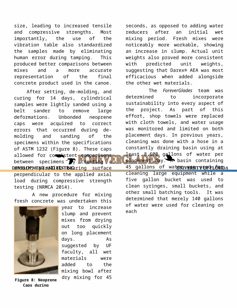
After setting, de-molding, and curing for 14 days, cylindrical samples were lightly sanded using a belt sander to remove large deformations. Unbonded neoprene caps were acquired to correct errors that occurred during de-molding and sanding of the specimens within the specifications of ASTM 1232 (Figure 8). These caps allowed for consistent comparisons between specimens by creating a smooth, parallel bearing surface perpendicular to
the applied axial load during compressive strength testing (NRMCA 2014). A new procedure for mixing fresh concrete was undertaken this year to increase slump and prevent
mixes from drying out too quickly on long placement days. As suggested by UF faculty, all wet materials were added to the mixing bowl after dry mixing for 45 seconds, as opposed to adding water reducers after an initial wet mixing period. Fresh mixes were noticeably more workable, showing an increase in slump. Actual unit weights also proved more consistent with predicted unit weights, suggesting
that Darex® AEA was most efficacious when added alongside the other wet materials. The ForeverGlades team was determined to incorporate sustainability into every aspect of the project. As part of this effort, shop towels were replaced with cloth towels, and water usage was monitored and limited on both placement days. In previous years, cleaning was done with a hose in a constantly draining basin using at least 8,600 gallons of water per placement day. A basin containing 45 gallons of water was used for cleaning large equipment while a five gallon bucket was used to clean syringes, small buckets, and other small batching tools. It was determined that merely 140 gallons of water were used for cleaning on eachplacement day.
The glass particles constituting all sizes of Poraver® aggregate are recycled, providing a level of environmental sustainability mirrored by the recycled glass powder of VCAS™ 160. Ground blast furnace slag represents another sustainable material, as its use in concrete precludes its environmentally-harmful disposal as an industrial by-product. Substantial donations of materials, including white Portland cement, slag, S38, K15, and all admixtures, save Sika® Latex R, were secured. Economic sustainability was thereby maximized for the mix design phase of the project. Like many of its predecessors, ForeverGlades includes three layers of concrete. In previous years, the larger-sized aggregates would become dislodged during troweling, producing a rough surface. This year, a mix excluding larger-sized aggregates was used for both the inner and outer layers, rather than just the outermost layer of the canoe, as was the case in AcceleGator (2014). This omission allowed for an increase in surface area and decrease in void quantity, ultimately creating a more aesthetically-pleasing boat with decreased drag. The mix design including all sizes of Poraver® proved to be strongest in tension and compression; it was therefore used in the middle layer and structural ribs to provide flexural support throughout the boat. Finally, the inner two layers and the ribs contain basalt fibers to aid in tension and flexure. Kevlar®-impregnated carbon fiber mesh was used as structural reinforcement and was embedded between each layer of the canoe. Strips of the mesh were also placed in between two lifts of concrete when hand-placing the structural ribs. The final mixes determined for ForeverGlades developed strengths that exceeded the requirements set by the
structural anaylsis and can be found in Table 2.
Figure 8: Neoprene Caps during Compression Test
Table 2: ForeverGlades Concrete Properties Compared to AcceleGator
Inner Layer
Middle Layer
Outer Layer
Structural Ribs
Aesthetic Paste
AcceleGator Inner
AcceleGato r Outer
Wet Unit Weight 50.5 pcf 54.2 pcf 49.5 pcf 55.2 pcf 120.0 pcf 47.7 pcf 49.3 pcfDry Unit Weight 40.6 pcf 50.3 pcf 40.7 pcf 52.7 pcf 105.8 pcf 36.1 pcf 35.2 pcf
w/cm Ratio 0.66 0.34 0.66 0.30 0.23 0.40 0.70Compressive Strength* 1,512 psi 2,148 psi 1,350 psi 1,666 psi NA 1,638 psi 1,339 psi
Tensile Strength* 195.5 psi 282.2 psi 128.9 psi 270.9 psi NA 121.3 psi 100.8 psiBasalt Chopped Fibers Yes Yes No Yes No No No
Latex SBR Sika®R SBR SBR No Sika®R Sika®RFlexural Strength* NA NA
Concrete Properties
1,272 psi 1,194 psi

With the move to an on-campus facility, the ForeverGlades team had to make several adjustments in order to better operate in the new space. The major change involved making the canoe form mobile in order to reduce spatial and logistical problems within the lab. This meant eliminating the table on which the form had been built in the past and constructing the form directly on a steel beam. Heavy-duty casters were attached to the beam, allowing it to be easily maneuvered. Eliminating the table surface cut this year’s team’s plywood use in half. The form’s mobility allowed sanding to be done outside of the lab, reducing respiratory concerns within the team’s confined area. This also enabled the team to accommodate ever-changing research projects within the shared lab space. Based on the team’s experience level and the ability to better regulate layer thickness while shotcreting, a male form was chosen for ForeverGlades. Rather than having it CNC milled, the form was crafted by hand. This method allowed the team to stay within its budget and familiarize newer team members with the level of precision that would later be required during placement. Instead of foam, the team chose to use wood as the primary material in constructing the form. This choice was motivated by the sustainable harvesting of the available lumber and the ability to reuse pieces of the previous year’s form. Cross sections at 1 ft. increments were obtained from the design software, then printed and cut from ¾ in. plywood. The cross sections were cut with an added rectangular piece at their bases, allowing them to fit directly into the beam. The cross sections were also cut with a lip at the gunwales. This lip
was designed at the desired thickness of the canoe to ensure uniformity when troweling on placement day. The steel beam contains holes every 4 in. on-center, enabling better accuracy in placing the sections at 1 ft. increments. The rigidity of the beam also aided in keeping the cross
sections aligned. Plywood spacers and wooden triangles braced each side of the sections and were bolted to the beam (Figure 9). Once every section was in place, a transit level was used to align each one along the hull’s centerline. The construction team nailed ½ in. wide plywood strips to the edges of the cross sections, connecting them and forming the canoe’s curved shape. A 5/16 in. thickness was chosen for these strips because it provided enough flexibility to follow the hull’s contours but enough rigidity to resist deflection during sanding. Once completed, the team used a belt sander to make an initial pass over the entire form before applying Bondo® to fill in gaps and depressions. Repeated sanding and Bondo® applications resulted in a smooth, even form surface. The entire form was then coated in a laminating resin to waterproof the wood. When the resin was completely cured, precut adhesive foam designs were applied to the form in order to create an inlaid effect in the concrete. Insulation foam was used instead of wood to create the finer details of the hull’s shape. The bow and stern sections of the hull were sculpted from layered foam using a variable speed orbital sander to achieve the shape prescribed by the FREE!ship (Timoshenko 2013) file. The three structural rib sections were carefully hand-sanded to achieve roughly the desired profile. A meticulous application of Bondo® provided the freedom to create the preferred trapezoidal shape (Figure 10). The chamfered design was implemented to ease demolding and mitigate stress concentrations by reducing sharp inside corners. The ForeverGlades team made it a priority to optimize the lengthy placement day process where possible. The practice placement day was scrutinized by team captains, and changes were implemented for competition placement day. The team acquired a second donated shotcrete gun, and the number of trowelers that were trained and Figure 9: Cross Sections
Supported and Bolted to Beam
Figure 10: Structural Rib Form
utilized was doubled for the competition placement day. This allowed the team to work on larger sections of the canoe more efficiently and finish troweling before the concrete became unworkable. The team began placement day by thoroughly applying vegetable oil to the form as a natural release agent. Next, two layers of concrete were hand-placed in each rib, with a strip of carbon fiber mesh reinforcement embedded between them. Immediately thereafter, the first layer was shotcreted and troweled to a ruled thickness of 1/8-in.; marked pins were used by trowelers to ensure a consistent thickness throughout each layer. Once complete, carbon fiber mesh was placed over the entire canoe and embedded into the first layer by hand. The next layer was also applied at 1/8 in., after which a second sheet of carbon fiber was embedded in the canoe. Layer thickness was carefully monitored at the gunwale lip. The final layer was applied thicker (3/16 in.) to allow the team to more effectively sand away exterior imperfections while maintaining the final thickness of 3/8 in. On this layer, the gunwale lip allowed team members to trowel straight up from its edge, ensuring regularity along the length of the canoe. Extra care was taken in finishing the outer layer to minimize the amount of time needed later for sanding. The canoe was then covered in plastic for the next three days to retain moisture as the concrete set. A new, modular curing tank was constructed to maximize the efficiency of the team’s limited lab
space. Since the tank could be easily disassembled, the side panel was removed and the entire form was rolled into the tank, while still attached to the beam. A water heater and soaker hose were used over the entire canoe to recirculate water infused with calcium hydroxide to aid in the curing process (Figure 11). A double layer of burlap ensured that the canoe’s surface remained moist. With
the tank acting as a catch basin, there was minimal
water loss during this phase of curing. At the end of the initial 14-day curing, the form was removed from the tank, and the canoe was de-molded. This time frame simulates the strength and age at which specimens were tested during the design phase. After using compressed air for the first time this year to separate the concrete from the wood, several team members were able to lift the canoe off of the wooden form. The foam sections used to shape the bow and stern were left in the canoe as flotation. The curing tank was then reassembled, filled with limewater, and the canoe was submerged for an additional two weeks at 135 ºF to complete curing. This system was able to achieve a higher temperature than first anticipated, allowing greater opportunity for strength gain than test specimens (NRMCA 2006). At the conclusion of the curing process, the canoe was removed from the tank, and concrete was hand-placed to cover the flotation at the bow and stern. Minor air voids in the hull’s interior were also filled in at this time. The interior and exterior of the canoe were carefully hand sanded to remove imperfections and create the optimum surface for applying sealer. Long, wooden sanding blocks were used to mitigate “waviness” along the outside walls of the canoe. Incrementally moving from 100 to 220 grit sandpaper helped the team achieve the optimal finish for sealer. To better integrate this year’s theme into the construction of ForeverGlades, the team decided to incorporate a three-dimensional alligator on the interior of the hull (Figure 12). The three portions of the alligator’s body were sculpted from clay, and a corn starch and silicone mixture was used to create flexible molds. To maintain continuity with the canoe, the fine, inner layer mix was used to cast the alligator. A special mix was created to bond it to the hull. The alligator was then strategically placed in the canoe based upon aesthetics and paddler safety. ForeverGlades was then thoroughly cleaned before carefully applying colored sealer.
Figure 11: Initial Curing with Heated Soaker Hose
Figure 12: Aesthetic Alligator in Practice
Canoe
ASCE/NCCC. (2015). “2015 American Society of Civil Engineers National Concrete CanoeCompetition. Rules and Regulations.” <http://www.asce.org/uploadedFiles/Membership_and_Communities/Student_Chapters/Concrete_Canoe/Content_Pieces/nccc-rules-and-regulations.pdf> (Feb. 18, 2015).
ASTM (2014). “Standard Practice for Use of Unbonded Caps in Determination of Compressive Strength of Hardened Concrete Cylinders.” C1231/C1231M-14. West Conshohocken, PA.
ASTM (2010). “Standard Specifications for Air-Entraining Admixtures for Concrete.” C260/C260M – 10a, West Conshohocken, PA.
ASTM (2013). “Standard Specification for Chemical Admixtures for Concrete.” C494/C494M – 13, West Conshohocken, PA.
ASTM (2012). “Standard Specifications for Coal Fly Ash and Raw or Calcined Natural Pozzolan for Use in Concrete.” C618 – 12a, West Conshohocken, PA.
ASTM (2013). “Standard Specification for Concrete Aggregate.” C33/ C33M - 13, West Conshohocken, PA.
ASTM (2010). “Standard Specification for Fiber-Reinforced Concrete.” C1116/C1116M-10a. West Conshohocken, PA.
ASTM (2013). “Standard Specification for Latex and Powder Polymer Modifiers for use in Hydraulic Cement Concrete and Mortar.” C1428 – 13, West Conshohocken, PA.
ASTM (2012). “Standard Specification for Portland Cement.” C150/C150M – 12, West Conshohocken, PA.
ASTM (2013). “Standard Specification for Slag Cement for Use in Concrete and Mortars.” C989/C989M – 13, West Conshohocken, PA.
ASTM (2013). “Standard Terminology Relating to Concrete and Concrete Aggregates.” C125 – 13b,West Conshohocken, PA.
ASTM (2014). “Standard Test Method for Compressive Strength of Cylindrical Concrete Specimens.” C39/C39M-14, West Conshohocken, PA.
ASTM (2012). “Standard Test Method for Density, Relative Density (Specific Gravity), and Absorption of Fine Aggregates.” C128 – 12, West Conshohocken, PA.
ASTM (2013). “Standard Test Method for Density (Unit Weight), Yield, and Air Content (Gravimetric) of Concrete.” C138/C138M – 13a, West Conshohocken, PA.
ASTM (2010). “Standard Test Method for Flexural Strength of Concrete (Using Simple Beam with Third-Point Loading).” C78/C78M-10el, West Conshohocken, PA.
ASTM (2012). “Standard Test Method for Tensile Strength of Chemical-Resistant Mortar, Grouts, and Monolithic Surfacings.” C307-03(2012), West Conshohocken, PA.
Cheng Concrete (2014). “Cheng Concrete Exchange: Chopped Basalt Fiber.” <http://store.concreteexchange.com/CHENG-Concrete-Online-Store_5/Concrete-Additives-Fibers-and-Rebar/Chopped-Basalt-Fiber> (Dec 3, 2015).
Ferraro, Christopher C. (2009). “Determination of Test Methods for the Prediction of the Behavior of Mass Concrete.” Doctoral Dissertation, University of Florida, Gainesville, FL.
Gray Line (n.d.). “Allow Your Imagination to go Wild in the Everglades.” Digital image. <http://www.grayline.com/tours/miami/everglades-airboat-adventure-with-transportation-biscayne-boat-tour-5864_13/>. (Feb . 20, 2015).
Gullion, L (1994). Canoeing. Human Kinetics Publishers, Champaign, IL, 25-26.
Hossain, A.B., Shirazi, S.A., Persun, J., Neithalath, N. (2008). “Properties of Concrete Containing Vitreous Calcium Aluminosilicate Pozzolan.” Transportation Research Record No. 2070. Washington D.C.
Laine. (2011). Everglades Open Field. The Camp Host. Digital image. <http://thecamphost.blogspot.com/2011/02/paynes-prairie.html?m=1>. (Feb. 20, 2015).
Lazauskas, L. (2013) Michlet. [Software] <http://www.cyberiad.net/michlet.htm> (Sep. 27, 2014).
Lubeck, A., Gastaldini, A.L.G., Barin, D.S., Siqueira, H.C. (2011). “Compressive strength and electrical properties of concrete with white Portland cement and blast-furnace slag.” Federal Univeristy of Santa Maria. Rio Grande do Sul, Brazil.
Maki, K. J., Doctors, L. J., Beck, R. F., & Troesch, A. W. (2006). “Transom-stern flow for high-speedcraft.” Australian Journal of Mechanical Engineering, 3(2), 191.
Marcellini, P. (n.d.). “Blue and Orange.” Personal Photograph <http://www.paulmarcellini.com/photo/orange-and-blue/> (Feb 20, 2015).
Microsoft. (2010). Microsoft Excel [Software]. Redmond, Washington: Microsoft. (Oct. 21, 2014).
National Ready Mixed Concrete Association (NRMCA) (2006). “CIP 39-Maturity Methods to Estimate Concrete Strength.” < http://www.nrmca.org/aboutconcrete/cips/39p.pdf> (Feb. 18, 2015).
National Ready Mixed Concrete Association (NRMCA) (2014). “Technology in Practice.” < http://www.nrmca.org/aboutconcrete/downloads/Tip5.pdf> (Feb. 20, 2015).
National Park Service. (2015). “Everglades National Park (U.S. National Park Service).” <http://www.nps.gov/ever/index.htm> (Feb. 23, 2015).
Paradis, R. and Gendron, G. (2006) “Structural Behavior Analysis of a Concrete Canoe.” Concrete Canoe Magazine, Vol. 1, No.1, Spring 2006, pp 18 – 26.
Timoshenko, V. F. (2013). FREE!Ship Plus (Version 3.41) [Software]. < http://freeshipplus.pisem.su/indexEN.html> (Aug. 3, 2014).
TorayCA (2014). T300 Data Sheet. Toray Carbon Fiber America. Santa Ana, CA.
University of Florida, Concrete Canoe. (2007) Gladigator. NCCC Design Paper, University of Florida, Gainesville, Florida.
University of Florida, Concrete Canoe. (2014) AcceleGator. NCCC Design Paper, University of Florida, Gainesville, Florida.
University of Florida. (2014). “Facts and Rankings.” < http://www.ufl.edu/about-uf/facts-and-rankings/> (Feb. 7, 2015).
Winters, J. (2006). “The Shape of the Canoe.” Green Valley Boat Works (CD-ROM), Ontario, Canada.