Embed Size (px)
Citation preview

Executive Summary.......................................................................................................................iiProject Management.......................................................................................................................1Organization Chart.........................................................................................................................2Hull Design and Structural Analysis .............................................................................................3Development and Testing ..............................................................................................................5Construction...................................................................................................................................8Project Schedule ..........................................................................................................................10Design Drawing ...........................................................................................................................11LIST OF FIGURESFigure 1: Distribution of Person Hours..........................................................................................1Figure 2: Distribution of Funds......................................................................................................1Figure 3: Prototypes of Excalibur and Kryptoknight..................................................................... 3Figure 4:.Visual Analysis Model of Beam.....................................................................................4Figure 5: Visual Analysis Model of Lateral Cross Section............................................................4Figure 6: Shape Builder Custom Shape Cross Sections.................................................................4Figure 7: ASTM 39 Compression Test of Concrete Cylinders......................................................7Figure 8: S/W Ratios of Different Material Combination..............................................................7Figure 9: Image of Female Mold....................................................................................................8Figure 10: Thickness Control.........................................................................................................8Figure 11: Placement of Reinforcement.........................................................................................9LIST OF TABLESTable 1: Excalibur Specifications..................................................................................................iiTable 2: Concrete and Reinforcement Properties..........................................................................iiTable 3 Results from Flume Test..................................................................................................3Table 4 Maximum Moment Values...............................................................................................3Table 5: Maximum Stresses...........................................................................................................5Table 6: Admixture Changes/Dosages........................................................................................... 5Table 7: Mix Type Designation......................................................................................................7APPENDICESAppendix A – References..........................................................................................................A-1Appendix B – Mixture Proportions ...........................................................................................B-1Appendix C – Bill of Materials .................................................................................................C-1Appendix D – Structural Hand Calculation...............................................................................D-1
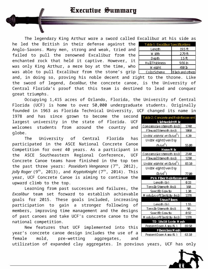
The legendary King Arthur wore a sword called Excalibur at his side as he led the British in their defense against the Anglo-Saxons. Many men, strong and weak, tried and failed to pull the renowned Excalibur from the enchanted rock that held it captive. However, it was only King Arthur, a mere boy at the time, who was able to pull Excalibur from the stone’s grip and, in doing so, proving his noble decent and right to the throne. Like the sword of legend, Excalibur, the concrete canoe, is the University of Central Florida’s proof that this team is destined to lead and conquer great triumphs.
Occupying 1,415 acres of Orlando, Florida, the University of Central Florida (UCF) is home to over 50,000 undergraduate students. Originally founded in 1963 as Florida Technical University, UCF changed its name in 1978 and has since grown to become the second largest university in the state of Florida. UCF welcomes students from around the country and globe.
The University of Central Florida has participated in the ASCE National Concrete Canoe Competition for over 40 years. As a participant in the ASCE Southeastern Regional Conference, UCF Concrete Canoe teams have finished in the top ten the past three years: Poseidon’s Vengeance (7th, 2012), Jolly Roger (9th, 2013), and KryptoKnight (7th, 2014). This year, UCF Concrete Canoe is aiming to continue the upward climb to the top.
Learning from past successes and failures, the Excalibur team set forward to establish achievable goals for 2015. These goals included, increasing participation to gain a stronger following of members, improving time management and the designs of past canoes and take UCF’s concrete canoe to the national competition.
New features that UCF implemented into this year’s concrete canoe design includes the use of a female mold, pre-wetting aggregates, and utilization of expanded clay aggregates. In previous years, UCF has only experimented with male molds, but this year the team decided to move forward with a female mold application with the goal of ensuring the 2015 canoe had a smooth and precise outer layer. The improved outer later was to aid Excalibur to stay on a straight path during racing. Another goal that UCF established was to increase the overall strength of the canoe by improving the internal curing. In Excalibur’s mix design, expanded clay was used to increase the strength and reinforcement of the overall canoe. Submerging the aggregates for 15 hours before incorporating them in a mix was also increased the strength.
Length 19.5 ftWidth 2.79 ftDepth 1.5 ft
Hull Thickness 9/16 inWeight 450 lb
Color Scheme Black and others
Table 1: Excalibur Specifications
Compressive strength (psi) 1740Flexural Strength (psi) 1060
Unit Weight Wet (lb/yd3) 6.20Unit Weight Oven Dry
(lb/yd3) 55.00
Compressive strength (psi) 2140Flexural Strength (psi) 1230
Unit Weight Wet (lb/yd3) 83.10Unit Weight Oven Dry
(lb/yd3) 77.00
Length (in) 0.33Tensile Strength (ksi) 160
Specific Gravity 1.30Modulus of Elasticity (ksi) 1378
Length (in) 1.55Tensile Strength (ksi) 90
Specific Gravity 0.92Modulus of Elasticity (ksi) 1378
Percent Open Area (%) 69.50
Percent Open Area (%) 63.10
Table 2: Concrete and Reinforcement
TD 10x10 Scrim Mesh
Fiberglass Mesh
PVA Fiber Reinforcement
Lightweight Mix
Heavy Mix
Strux Fibers
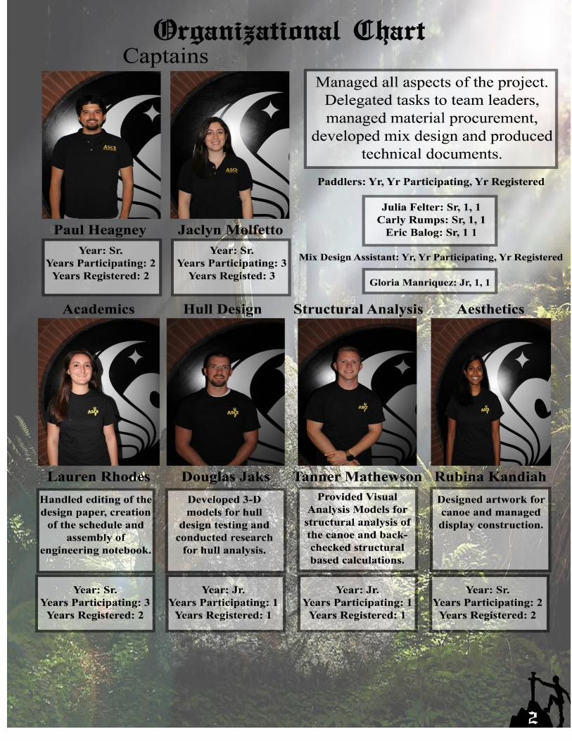
The project management for Excalibur consisted of organized groups within the concrete canoe team. Four different teams were established to focus on the main aspects of the competition including mix design, aesthetics, construction, and design paper. Leadership positions were chosen by the captains from a pool of devoted concrete canoe members. Since quality control was a high priority, the captains oversaw each team by establishing weekly meetings to ensure that each group was on track to success. A detailed schedule was created and a critical path was determined so that potential challenges and risks could be mitigated.
The following goals were set: better pour day preparation, improved time management, and a more efficient mix and mold design. With a team consisting of predominantly new members it was immensely
important to the successful completion of Excalibur to have a practice pour day. This allowed for the team to be exposed to troweling methods, thickness control techniques and practices, efficient mixing methods, and important safety measures and practices upheld at our shop. The practice pour day minimized unnecessary delays in between layer placements and reduced error in the final product.
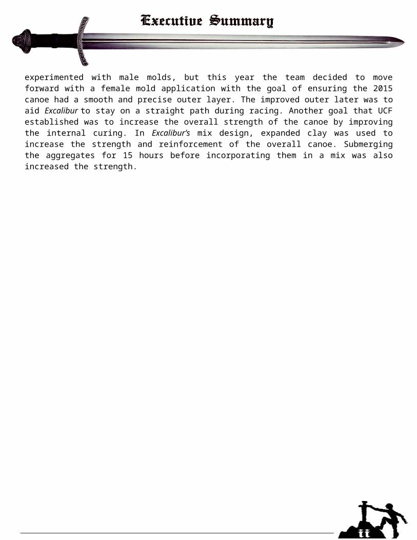
The dedication of the Excalibur concrete canoe team accumulated a total of 2,975 person-hours. A further breakdown of the person-hours is represented in Figure 1. The majority of hours were dedicated to designing the concrete mix. After extensive research, the team mixed and tested over 8 different mix designs and then narrowed it down to two mixes that were perfected by adjusting mix proportions.
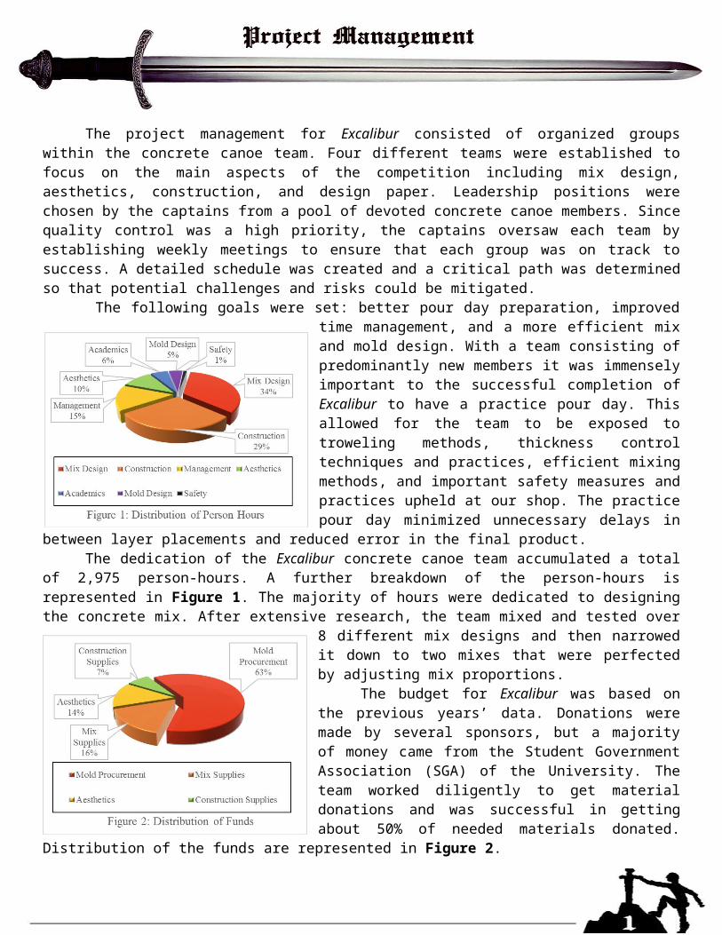
The budget for Excalibur was based on the previous years’ data. Donations were made by several sponsors, but a majority of money came from the Student Government Association (SGA) of the University. The team worked diligently to get material donations and was successful in getting about 50% of needed materials donated. Distribution of the funds are represented in Figure 2.
When establishing the critical path a look was taken at past canoes were observed and the areas that had the greatest amount of lag time. Our critical path activities consisted of material procurement, practice pour day, mix design testing,
and the final pour date. In developing the schedules, actual start and actual finish days were accounted for each objective. As the mix design testing and research continued, it was found that the critical path pushed to the maximum because of unexpected delays that occurred during the procurement process. Due to a backorder on one of the main aggregates, our mix schedule was pushed back 3 weeks, and in turn, delaying the final pour day. In order to remain on schedule, test cylinders were cured for 21 days instead of the optimal 28 days.
At the beginning of every new school year, the ASCE student chapter hosts a “shop tour” to familiarize new members with the tools and organization of the shop. Keeping the shop clean and structured ensures the safety of the members using it. During the shop tour, safety procedures and expectations are discussed to communicate to members of the importance of safety.
Our design selection focused on three primary factors: maneuverability, straight line speed, and stability. Looking at past designs and researching the varying types of hull geometries and rockers we found that the previous year’s canoe, KryptoKnight had successfully achieved our goals. With this, the hull design for Excalibur was based heavily on the 2014 design of KryptoKnight. KryptoKnight became this year’s practice canoe for rowing during the late summer and early fall semesters. As the team was able to test, the design of KryptoKnight proved to be highly efficient in the water with minor problems concerning straight line speed and maneuverability in non-ideal conditions. Keeping this in mind, the team decided to keep some of the design aspects the same as KryptoKnight such as depth, width, and shape of the overall design. An in-depth literature review was conducted to learn how to fix the underlying problems mentioned above. After consulting a nautical engineer and our contacts for the female mold minor alterations were made to the design which improved both the straight line speed and maneuverability of the canoe.
An analysis of the possible race courses and observations of the strengths and weaknesses of this year’s rowing team guided the changes made to KryptoKnight to create Excalibur’s Design. From early rowing
sessions it was determined that maneuverability was one of the most important factors as it affected tracking ability as well as efficiently turning and correcting course. The paddling team had problems with implementing the different strokes in order to keep the canoe tracking adequately. Excalibur has a more
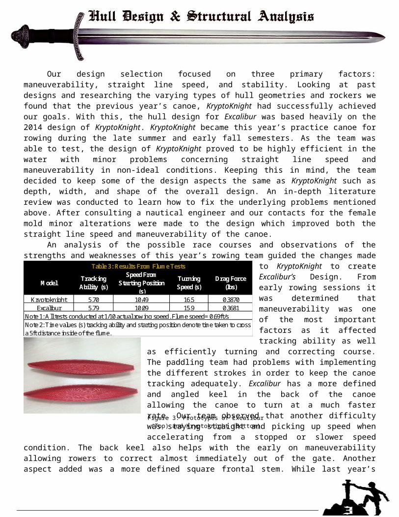
defined and angled keel in the back of the canoe allowing the canoe to turn at a much faster rate. Our team observed that another difficulty was staying straight and picking up speed when accelerating from a stopped or slower speed condition. The back keel also helps with the early on maneuverability allowing rowers to correct almost immediately out of the gate. Another aspect added was a more defined square frontal stem. While last year’s design utilized a more angled square stem that proved to be more efficient at cutting the water and maintaining speed, it was seen to negatively impact the maneuverability since both the front and back of the canoe now had some control over turning capability.
To test the effects of these changes, two representative 1:20 scales prototypes of KryptoKnight and Excalibur were created and tested in a hydraulic flume (Figure 3). The variables tested included turning time, start off speed, and the ability to sustain tracking speed. The flume proved to be valuable at giving us accurate turning speeds, but it had problems when testing straight line speed. The models kept dragging along the wall and proved to be problematic. Instead, the speed test was
conducted in a 5-in inner diameter circular pipe. This helped eliminate the error caused by the flume. Table 3 shows the data for turning time and drag forces obtained from these tests.
ModelTracking Ability (s)
Speed From Starting Position
(s)
Turning Speed (s)
Drag Force (lbs)
Kryptoknight 5.70 10.49 16.5 0.3870Excalibur 5.79 10.09 15.9 0.3681
Note 2: Time values (s) tracking ability and starting position denote time taken to cross a 5ft distance inside of the flume.
Table 3: Results From Flume Tests
Note 1: All tests conducted at 1/10 actual rowing speed. Flume speed= 0.69ft/s
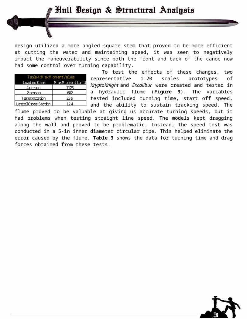
Loading Case Max Moment (lb-ft)4 person 11252 person 602
Transportation 23.9Lateral Cross Section 12.4
Table 4: Max Moment Values
Figure 3: Prototypes of Excalibur (Top) and Kryptoknight (Bottom)
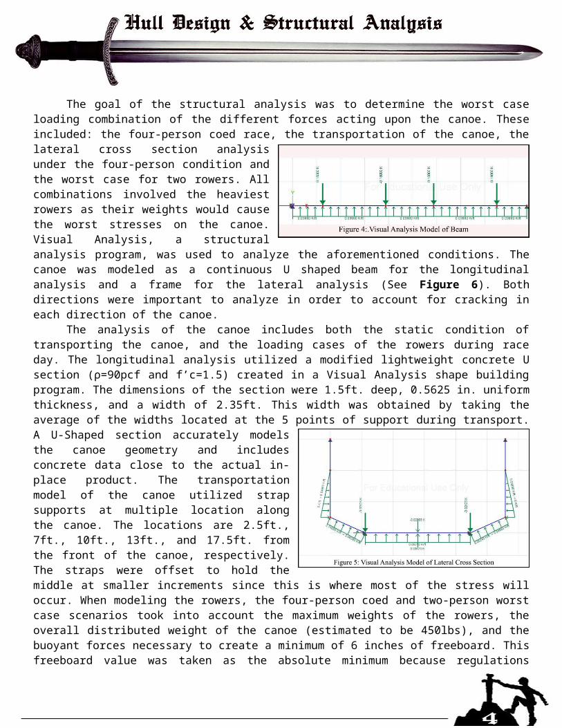
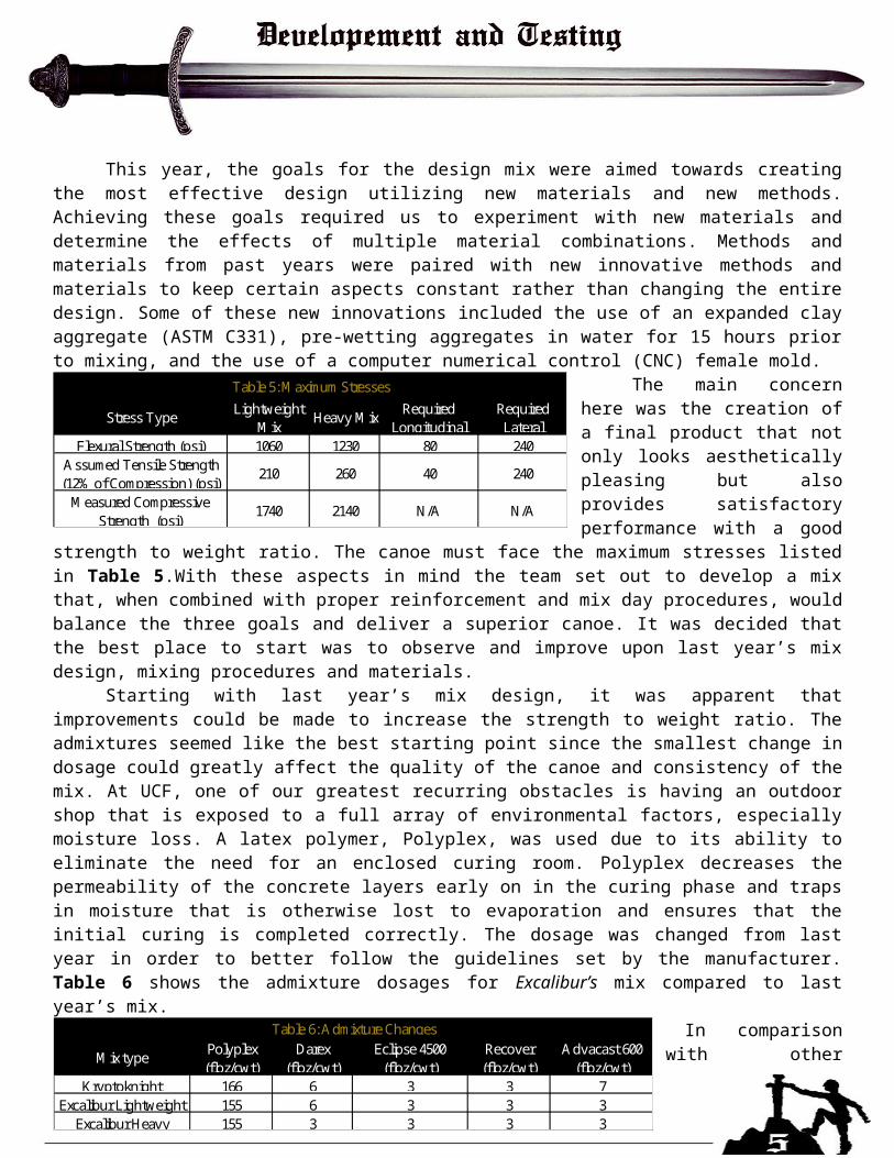
The goal of the structural analysis was to determine the worst case loading combination of the different forces acting upon the canoe. These included: the four-person coed race, the transportation of the canoe, the lateral cross section analysis under the four-person condition and the worst case for two rowers. All combinations involved the heaviest rowers as their weights would cause the worst stresses on the canoe. Visual Analysis, a structural analysis program, was used to analyze the aforementioned conditions. The canoe was modeled as a continuous U shaped beam for the longitudinal analysis and a frame for the lateral analysis (See Figure 6). Both directions were important to analyze in order to account for cracking in each direction of the canoe.
The analysis of the canoe includes both the static condition of transporting the canoe, and the loading cases of the rowers during race day. The longitudinal analysis utilized a modified lightweight concrete U section (ρ=90pcf and f’c=1.5) created in a Visual Analysis shape building program. The dimensions of the section were 1.5ft. deep, 0.5625 in. uniform thickness, and a width of 2.35ft. This width was obtained by taking the average of the widths located at the 5 points of support during transport. A U-Shaped section accurately models the canoe geometry and includes concrete data close to the actual in-place product. The transportation model of the canoe utilized strap supports at multiple location along the canoe. The locations are 2.5ft., 7ft., 10ft., 13ft., and 17.5ft. from the front of the canoe, respectively. The straps were offset to hold the middle at smaller increments since this is where most of the stress will occur. When modeling the rowers, the four-person coed and two-person worst case scenarios took into account the maximum weights of the rowers, the overall distributed weight of the canoe (estimated to be 450lbs), and the buoyant forces necessary to create a minimum of 6 inches of freeboard. This freeboard value was taken as the absolute minimum because regulations require at least 4- ½” to show school lettering at all times. This also accounts for any miscalculation in the weight of the canoe as the real weight is variable. See Figure 4 for the coed model.
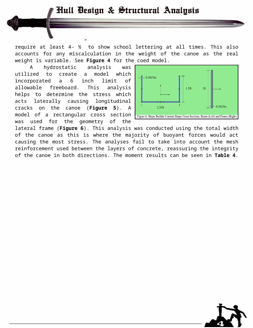
A hydrostatic analysis was utilized to create a model which incorporated a 6 inch limit of allowable freeboard. This analysis helps to determine the stress which acts laterally causing longitudinal cracks on the canoe (Figure 5). A model of a rectangular cross section was used for the geometry of the lateral frame (Figure 6). This analysis was conducted using the total width of the canoe as this is where the majority of buoyant forces would act causing the most stress. The analyses fail to take into account the mesh reinforcement used between the layers of concrete, reassuring the integrity of the canoe in both directions. The moment results can be seen in Table 4.
This year, the goals for the design mix were aimed towards creating the most effective design utilizing new materials and new methods. Achieving these goals required us to experiment with new materials and determine the effects of multiple material combinations. Methods and materials from past years were paired with new innovative methods and materials to keep certain aspects constant rather than changing the entire design. Some of these new innovations included the use of an expanded clay aggregate (ASTM C331), pre-wetting aggregates in water for 15 hours prior to mixing, and the use of a computer numerical control (CNC) female mold.
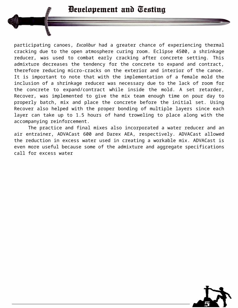
The main concern here was the creation of a final product that not only looks aesthetically pleasing but also provides satisfactory performance with a good strength to weight ratio. The canoe must face the maximum stresses listed in Table 5.With these aspects in mind
the team set out to develop a mix that, when combined with proper reinforcement and mix day procedures, would balance the three goals and deliver a superior canoe. It was decided that the best place to start was to observe and improve upon last year’s mix design, mixing procedures and materials.
Starting with last year’s mix design, it was apparent that improvements could be made to increase the strength to weight ratio. The admixtures seemed like the best starting point since the smallest change in dosage could greatly affect the quality of the canoe and consistency of the mix. At UCF, one of our greatest recurring obstacles is having an outdoor shop that is exposed to a full array of environmental factors, especially moisture loss. A latex polymer, Polyplex, was used due to its ability to eliminate the need for an enclosed curing room. Polyplex decreases the permeability of the concrete layers early on in the curing phase and traps in moisture that is otherwise lost to evaporation and ensures that the initial curing is completed correctly. The dosage was changed from last year in order to better follow the guidelines set by the manufacturer. Table 6 shows the admixture dosages for Excalibur’s mix compared to last year’s mix.
In comparison with other participating canoes, Excalibur had a greater chance of experiencing thermal cracking due to the open
atmosphere curing room. Eclipse 4500, a shrinkage reducer, was used to combat early cracking after concrete setting. This admixture decreases the tendency for the concrete to expand and contract, therefore reducing micro-cracks on the exterior and interior of the canoe. It is important to note that with the implementation of a female mold the inclusion of a shrinkage reducer was necessary due to the lack of room for the concrete to expand/contract while inside the mold. A set retarder, Recover, was implemented to give the mix team enough time on pour day to properly batch, mix and place the concrete before the initial set. Using Recover also helped with the proper bonding of multiple layers since each layer can take up to 1.5 hours of hand troweling to place along with the accompanying reinforcement.
The practice and final mixes also incorporated a water reducer and an air entrainer, ADVACast 600 and Darex AEA, respectively. ADVACast allowed the reduction in excess water used in creating a workable mix. ADVACast is even more useful because some of the admixture and aggregate specifications call for excess water
Stress Type Lightweight Mix
Heavy Mix Required Longitudinal
Required Lateral
Flexural Strength (psi) 1060 1230 80 240Assumed Tensile Strength (12% of Compression) (psi)
210 260 40 240
Measured Compressive Strength (psi)
1740 2140 N/A N/A
Table 5: Maximum Stresses
Mix type Polyplex (floz/cwt)
Darex (floz/cwt)
Eclipse 4500 (floz/cwt)
Recover (floz/cwt)
Advacast 600 (floz/cwt)
Kryptoknight 166 6 3 3 7Excalibur Lightweight 155 6 3 3 3
Excalibur Heavy 155 3 3 3 3
Table 6: Admixture Changes
when mixing for increased workability. The ADVACast also influenced the consolidation of the mix, allowing the concrete to have a more workable slump. This quality helped with forming the bow and stern of the canoe inside of the tight spaces of the female mold. Darex AEA was he controlling factor when it came to density management of the batches. The dosage of this product was kept similar to values of previous years for the lighter mix. For the heavy mix, the dosage was halved in order to keep the mix workable.
The previously used pozzolan, UltraPozz, was seen to work well with last year’s mix and was reused this year. The pozzolan has a lower density when compared to Portland Cement Type 1. This greatly helps with lowering the overall density of the final product while keeping adequate strength. In the past, the use of a pozzolan was seen to increase the bonding between layers of concrete due to the increased binding of aggregates. Proven to work well, this product was used in the creation of Excalibur. The tight binding helps reduce the permeability of the concrete which, along with the use of other materials, increases the durability of the canoe. The pozzolan also creates a nice white finish to allow easier implementation of aesthetics. The cementitious material ratio used last year was seen to be satisfactory and remained unchanged.
Reinforcement consisted of primary and secondary types of reinforcement. The primary reinforcement used is a combination of fiberglass mesh, GlassGrid 8511, and an AR scrim mesh, TD 10x10. Two different reinforcement types were used to ensure that there was a good dispersion of the tensile forces that Excalibur could experience. There were problems last year during the construction of the canoe, more specifically, the bonding of the canoe layers through the small reinforcement holes of the Scrim. The decision was made to increase the size of the Scrim from 5mm to 10mm openings. Two types of reinforcement fibers, PVA and Strux 90/40, were used as secondary reinforcement. The use of fibers helped with the tensile forces the canoe would experience on multiple planes. The fibers also provided a secondary benefit by holding concrete together during placement on the mold. The PVA fibers bind to the concrete on a molecular level, furthering the flexural strength of the concrete.
There was a major overhaul in the aggregate design of Excalibur’s mix. Poraver recycled glass was used again for its proven success in past mix designs and for its sustainability. The main differences in our aggregates come in the addition of expanded clay aggregates. The idea of using expanded clay came from observing the success of other schools that had used clay in previous years. With this in mind we set off to recreate that success in our mix design. The larger expanded clay aggregates are more efficient at holding water than poraver expanded glass. The absorption ability of the clay, at a Saturated Surface Dry (SSD) condition, proved to increase internal curing of the concrete. This process, combin ed with surface curing methods, increases the amount of strength developed over longer periods of time. Multiple combinations of aggregates were created and tested in order to see which yielded the best results. An important factor in choosing the mix is the ability for us to replicate it precisely multiple times for pour day.
Initial testing and mixing procedures also began with KryptoKnight’s design. KryptoKnight was chosen as a baseline since it was the only canoe, in recent history, to experiment with a latex polymer. Also, the materials were readily available for testing. The mix design from last year was recreated in order to test the ability of the team and to gain data in order to see which direction to move in. By doing this we were able to see which previously used mixing procedures could be improved up. By speaking to experts about material usage and combinations during mixing we were able to do just that.
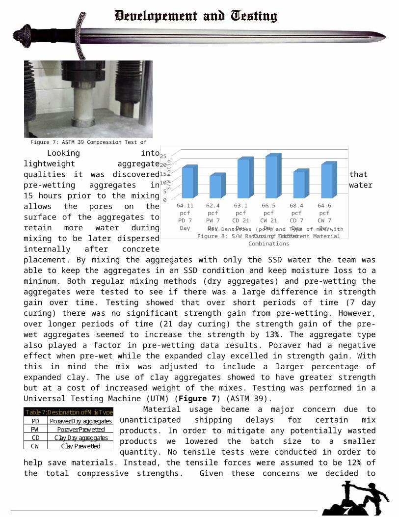
Looking into lightweight aggregate qualities it was discovered that pre-wetting aggregates in water 15 hours prior to the mixing allows the pores on the surface of the aggregates to retain more water during mixing to be later dispersed internally after concrete placement. By mixing the aggregates with only the SSD water the team was able to keep the aggregates in an SSD condition and keep moisture loss to a minimum. Both regular mixing methods (dry aggregates) and pre-wetting the aggregates were tested to see if there was a large difference in strength gain over time. Testing showed that over short periods of time (7 day
curing) there was no significant strength gain from pre-wetting. However, over longer periods of time (21 day curing) the strength gain of the pre-wet aggregates seemed to increase the strength by 13%. The aggregate type also played a factor in pre-wetting data results. Poraver had a negative effect when pre-wet while the expanded clay excelled in strength gain. With this in mind the mix was adjusted to include a larger percentage of expanded clay. The use of clay aggregates showed to have greater strength but at a cost of increased weight of the mixes. Testing was performed in a Universal Testing Machine (UTM) (Figure 7) (ASTM 39).
Material usage became a major concern due to unanticipated shipping delays for certain mix products. In order to mitigate any potentially wasted products we lowered the batch size to a smaller quantity. No tensile tests were conducted in order to help save materials. Instead, the tensile forces were assumed to be 12% of the total compressive strengths. Given these concerns we decided to implement two different types of mixes. One mix consisted of our best
strength to weight ratio mix that utilized clay and a variation of Poraver grain sizes. The second mix was our strongest mix consisting of the expanded clay and our smallest Poraver size, .1-.3mm. beads. The lightweight mix benefitted most from pre-wetting. The heavy mix had a decent ratio but was more workable which allowed for better consolidation during the placement. Our goal was to obtain the benefits of both the lightweight and heavy mixes.
Use of sustainable materials in Excalibur’s design was of utmost importance. The use of recycled materials such as Poraver recycled glass allowed for the creation of an economical mix design that meets all the requirements of our lightweight design. Expanded clay is highly durable and can be reused after being soaked or dried out. These benefits transfer into the concrete mix creating a product that is strong, durable, and resistant to thermal change. It allows for less use materials due to the expanded and porous nature of the clay. The use of HessPozz pozzolan allowed for even greater sustainability due to the overall consistency, purity, and chemical benefits the pozzolan provided. The pozzolan allowed for lighter coloration of the concrete reducing paint
64.11 pcf 62.4 pcf 63.1 pcf 66.5 pcf 68.4 pcf 64.6 pcfPD 7 Day PW 7 Day CD 21 Day CW 21 Day CD 7 Day CW 7 Day
0
5
10
15
20
25
Figure 8: S/W Ratios of Different Material CombinationsMix Densities (pcf) and Type of mix with Curing Period
S/W
Rati
o
PD Poraver Dry aggregatesPW Poraver PrewettedCD Clay Dry agreggatesCW Clay Prewetted
Table 7: Designation of Mix Type
Figure 7: ASTM 39 Compression Test of Concrete Cylinders
coatings for the aesthetics implementation. The purity of the pozzolan assured that there would be a mitigation of error when it came to the cementitious portion of the mix. Lastly, the pozzolan also provided good alkaline silica reaction control therefore decreasing the decay rate of the concrete creating a long lasting product.
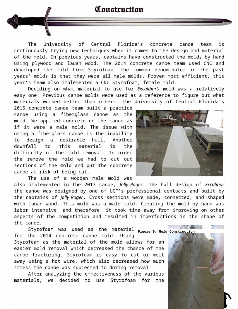
The University of Central Florida’s concrete canoe team is continuously trying new techniques when it comes to the design and material of the mold. In previous years, captains have constructed the molds by hand using plywood and lauan wood. The 2014 concrete canoe team used CNC and developed the mold from Styrofoam. The common denominator in the past years’ molds is that they were all male molds. Proven most efficient, this year’s team also implemented a CNC Styrofoam, female mold.
Deciding on what material to use for Excalibur’s mold was a relatively easy one. Previous canoe molds were used as a reference to figure out what materials worked better than others. The University of Central Florida’s 2015 concrete canoe team built a practice canoe using a fiberglass canoe as the mold. We applied concrete on the canoe as if it were a male mold. The issue with using a fiberglass canoe is the inability to design a desirable hull. Another downfall to this material is the difficulty of the mold removal. In order the remove the mold we had to cut out sections of the mold and put the concrete canoe at risk of being cut.
The use of a wooden male mold was also implemented in the 2013 canoe, Jolly Roger. The hull design of Excalibur the canoe was designed by one of UCF’s professional contacts and built by the captains of Jolly Roger. Cross sections were made, connected, and shaped with lauan wood. This mold was a male mold. Creating the mold by hand was labor intensive, and therefore, it took time away from improving on other aspects of the competition and resulted in imperfections in the shape of the canoe.
Styrofoam was used as the material for the 2014 concrete canoe mold. Using Styrofoam as the material of the mold allows for an easier mold removal which decreased the chance of the canoe fracturing. Styrofoam is easy to cut or melt away using a hot wire, which also decreased how much stress the canoe was subjected to during removal.
After analyzing the effectiveness of the various materials, we decided to use Styrofoam for the material and had it CNCed as the construction method of the mold. UCF also decided to have a female mold instead of the male mold. The female mold ensured that the concrete would stay true to the designed hull design. When applying concrete to a male mold, it is easy to lose the hull design because the outer layer of the concrete doesn’t have anything to maintain its shape.
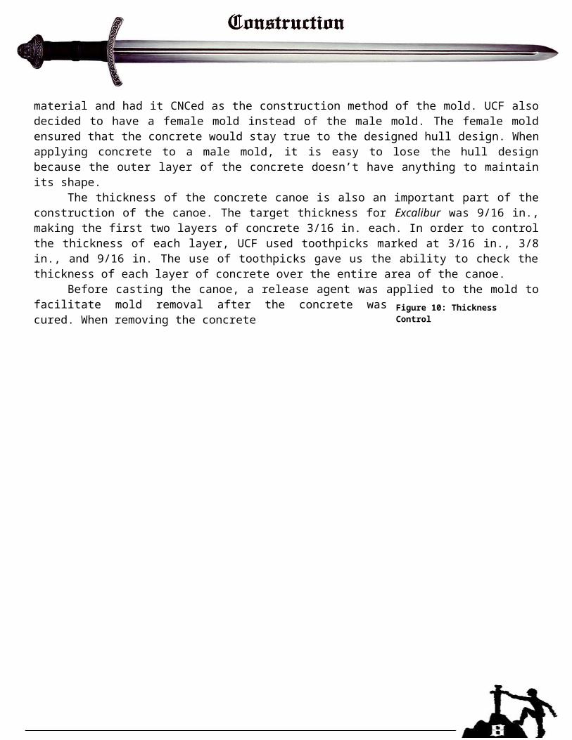
The thickness of the concrete canoe is also an important part of the construction of the canoe. The target thickness for Excalibur was 9/16 in., making the first two layers of concrete 3/16 in. each. In order to control the thickness of each layer, UCF used toothpicks marked at 3/16 in., 3/8 in., and 9/16 in. The use of toothpicks gave us the ability to check the thickness of each layer of concrete over the entire area of the canoe.
Before casting the canoe, a release agent was applied to the mold to facilitate mold removal after the concrete was cured. When removing the concrete
Figure 9: Mold Construction
Figure 10: Thickness Control
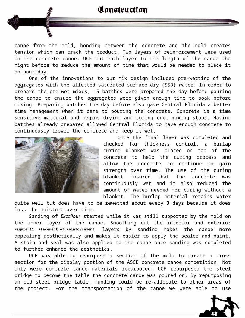
canoe from the mold, bonding between the concrete and the mold creates tension which can crack the product. Two layers of reinforcement were used in the concrete canoe. UCF cut each layer to the length of the canoe the night before to reduce the amount of time that would be needed to place it on pour day.
One of the innovations to our mix design included pre-wetting of the aggregates with the allotted saturated surface dry (SSD) water. In order to prepare the pre-wet mixes, 15 batches were prepared the day before pouring the canoe to ensure the aggregates were given enough time to soak before mixing. Preparing batches the day before also gave Central Florida a better time management when it came to pouring the concrete. Concrete is a time sensitive material and begins drying and curing once mixing stops. Having batches already prepared allowed Central Florida to have enough concrete to continuously trowel the concrete and keep it wet.
Once the final layer was completed and checked for thickness control, a burlap curing blanket was placed on top of the concrete to help the curing process and allow the concrete to continue to gain strength over time. The use of the curing blanket insured that the concrete was continuously wet and it also reduced the amount of water needed for curing without a blanket. The burlap material retains water quite well but does have to be rewetted about every 3 days because it does loss the moisture over time.
Sanding of Excalibur started while it was still supported by the mold on the inner layer of the canoe. Smoothing out the interior and exterior layers by sanding makes the canoe more appealing aesthetically and makes it easier to apply the sealer and
paint. A stain and seal was also applied to the canoe once sanding was completed to further enhance the aesthetics.
UCF was able to repurpose a section of the mold to create a cross section for the display portion of the ASCE concrete canoe competition. Not only were concrete canoe materials repurposed, UCF repurposed the steel bridge to become the table the concrete canoe was poured on. By repurposing an old steel bridge table, funding could be re-allocate to other areas of the project. For the transportation of the canoe we were able to use another steel bridge and alter it to be a cart for the finished concrete canoe.
Figure 11: Placement of Reinforcement
ASCE/NCCC (2015). “2015 American Society of Civil Engineers® National Concrete Canoe Competition™: Rules and Regulations.” <http://www.asce.org/uploadedFiles/Membership_and_Communities/Student_Chapters/Concrete_Canoe/Content_Pieces/nccc-rules-and-regulations.pdf>
University of Central Florida, Concrete Canoe. (2011) Knight's Sky. Design Paper, University of Central Florida, Orlando, Florida.
University of Central Florida, Concrete Canoe. (2012) Poseidon's Vengeance. Design Paper, University of Central Florida, Orlando, Florida.
University of Central Florida, Concrete Canoe. (2014) Kryptoknight. Design Paper, University of Central Florida, Orlando, Florida.
ASTM (2006). “Standard Test Method for Sieve Analysis of Fine and Coarse Aggregates.” C136-06, West Conshohocken, PA.
ASTM (2010). “Standard Specification for Air Entraining Admixtures for Concrete.” C260/C260M-10a, West Conshohocken, PA.
ASTM (2010). “Standard Specification for Fiber-Reinforced Concrete.” C1116/C1116M-10a, West Conshohocken, PA. ASTM (2010). “Standard Test Method for Flexural Strength of Concrete (Using Simple Beam with Third-Point Loading).” C78/C78M-10e1, West Conshohocken, PA
ASTM (2012). “Standard Specifications for Coal Fly Ash and Raw or Calcined Natural Pozzolan for Use in Concrete.” C618-12a, West Conshohocken, PA. ASTM (2012). “Standard Specification for Portland Cement.” C150/C150M-12, West Conshohocken, PA
ASTM (2012). “Standard Test Method for Compressive Strength of Cylindrical Concrete Specimens.” C39/C39M-12a, West Conshohocken, PA.
ASTM (2012). “Standard Test Method for Density, Relative Density (Specific Gravity), and Absorption of Fine Aggregate.” C128-12, West Conshohocken, PA.
ASTM (2012). “Standard Test Methods for Density (Unit Weight), Yield, and Air Content (Gravimetric) of Concrete.” C138/C138M-12a, West Conshohocken, PA.
ASTM (2012). “Standard Test Method for Slump of Hydraulic Cement Concrete.” C143/C143M-12, West Conshohocken, PA. ASTM (2013). “Standard Specification for Chemical Admixtures for Concrete.” C494/C494M-13, West Conshohocken, PA.
ASTM (2013). “Standard Specifications for Concrete Aggregates.” C33/C33M-13, West Conshohocken, PA.
ASTM (2014). “Standard Specification for Lightweight Aggregates for Concrete Masonry Units.” C331/C331M-14, West Conshohocken, PA.
Hibbeler, R. C. (2011). Mechanics of Materials, 8th Ed., Upper Saddle River, New Jersey.
Mamlouk, M., and Zaniewski, J. (2011). Materials for Civil and Construction Engineers, 3rd Ed. Upper Saddle River, New Jersey.
McCormac, J., and Brown R. (2014). Design of Reinforced Concrete, 9th Ed. Hoboken, New Jersey.
YD
SGAmount(lb/yd3)
Volume(ft3)
Amount(lb)
Volume(ft3)
Amount(lb/yd3)
Volume(ft3)
CM1 3.15 255.92 1.30 2.37 0.01 378.97 1.93CM2 2.60 400.29 2.47 3.71 0.02 592.75 3.65
656.21 3.77 6.08 0.03 971.71 5.58
F1 1.30 9.69 0.119 0.09 0.00 14.35 0.18F2 Strux Fibers 0.92 9.69 0.169 0.09 0.00 14.35 0.25
19.38 0.29 0.18 0.00 28.69 0.43
A1 Abs: 20% 0.39 0.000 0.000 0.00 0.000 0.00 0.000A2 Abs: 20% 0.47 0.000 0.000 0.00 0.000 0.00 0.000A3 Abs: 28% 0.59 0.00 0.000 0.00 0.000 0.00 0.000A4 Abs: 35% 0.90 305.917 5.447 2.83 0.050 453.00 8.066A5 Abs: 23% 1.59 131.107 1.325 1.21 0.012 194.14 1.962
437.024 6.772 4.047 0.063 647.15 10.03
W1 262.48 4.206 2.43 0.04 388.69 6.2341.04 0.38 60.77
221.44 2.05 327.91W2 1.00 107.07 0.99 158.55
369.55 4.21 3.42 0.04 547.24 6.23
S1 1.05 33.34 0.509 0.31 0.00 49.37 0.75333.34 0.51 0.31 0.00 49.37 0.75
Ad1 8.8 lb/gal 0.38 3.00 0.84 0.18 0.01 4.4 1.84Ad2 10.0 lb/gal 0.055 3.00 1.45 0.18 0.01 4.4 3.19Ad3 8.9 lb/gal 0.47 155.47 37.60 9.45 0.35 230.2 82.44Ad4 9.6 lb/gal 0.22 3.00 1.15 0.18 0.01 4.4 2.53Ad5 7.7 lb/gal 0.99 3.00 0.01 0.18 0.00 4.4 0.03
41.04 0.38 89.99
M
V
T
DD
A
Y
Ry
Mixture ID: Heavy MixDesign Proportions
(Non SSD)Actual Batched
ProportionsYielded
ProportionsDesign Batch Size (ft3):
Total Cementitious Materials: Fibers
PVA Fiber 8mm
0.25
Portland Cement Type 1Ultra pozz
Poraver .1-.3Expanded clay 3/16"
Total Aggregates: Water
Total Fibers: Aggregates
Poraver 1-2Poraver .5-1Poraver .25-.5
Total Water (W1 + W2) : Solids Content of Latex, Dyes and Admixtures in Powder Form
PolyplexTotal Solids of Admixtures:
Water for CM Hydration (W1a + W1b)1.00W1a. Water from Admixtures
W1b. Additional WaterWater for Aggregates, SSD
Water from Admixtures (W1a) :
Cement-Cementitious Materials Ratio 0.390 0.390 0.390
ADVA-Cast 600 (water)Darex AEA (air)PolyplexRecover (retarder)Eclipse (shrinkage)
Admixtures (including Pigments in Liquid Form) % Solids Dosage (floz/cwt)
Water in Admixture
Amount(fl oz)
Water in Admixtur
Dosage(floz/cwt)
Water in Admixtur
Water-Cementitious Materials Ratio 0.400 0.400 0.400Slump, Slump Flow, in . 4+/0.50in. 3.50 3.50
Theorectical Density, lb/ft 3 = (M / V) 97.49 97.49 97.49
Mass of Concrete. lbs 1515.50 14.03 2244.16
Absolute Volume of Concrete, ft 3 15.54 0.14 23.02
Design Density, lb/ft 3 = (M / 27) 56.13
Measured Density, lb/ft 3 83.117 83.12
Relative Yield = (Y / Y D ) 0.675
Air Content, % = [(T - D) / T x 100%] 42.43% 14.75% 14.75%
Yield, ft 3 = (M / D) 27 0.169 27
Material Quantity Units Unit Price Total
Portland Cement Type 1 75.68 lbs. $0.07 $5.30Ultra Pozz 118.39 lbs. $0.42 $49.72
Poraver® Sicsorspheres™ (1.0-2.0 mm) 20.8 lbs. $0.70 $14.56Poraver® Sicsorspheres™ (0.5-1.0 mm) 7.28 lbs. $0.70 $5.10Poraver® Sicsorspheres™ (0.1-0.3 mm) 64.98 lbs. $0.70 $45.49Expanded Clay (3/16") 35.82 lbs. $2.27 $81
ADVA®-Cast 600 0.046 gal $15.00 $0.69DAREX® AEA 0.065 gal $5.22 $0.34Polyplex® 2.35 gal $22.00 $51.70Recover® 0.046 gal $19.27 $0.89Eclipse® 4500 0.046 gal $23.64 $1.09
PVA Reinforcement fibers RSC-15 2.92 lbs. $7.99 $23.33Strux® 90/40 2.92 lbs. $10.00 $29.20
TD 10x10AR Scrim 120 sq. ft $0.28 $33.60
Styrofoam® CNCed Mold 1 LS $3,363.64 $3,363.64In & Out II Concrete Release Agent 0.25 gal $39.52 $9.88
Great Stuff Insulating Foam 6 Can $3.99 $23.94
Stain 9 gal $29.50 $265.50Sealer 2 gal $22.05 $44.10
Lettering 1 LS $135.56 $135.56$4,184.93Total Production Cost
Flotation Material
Stain and Sealer
Lettering
Female Mold and Related Items
Cementitious Materials
Aggregate
Admixtures
Fibers
Reinforcement
Assumptions Section is homogeneous, ignoring reinforcement of actual product. The section is of uniform thickness.
The longitudinal beam is modeled as 19.5ft in length and the lateral beam is 1.75ft in length. All beam analysis is considered simply supported.
The canoe weight is 450lbs total. The 2 heaviest male rower condition places the rowers (185lbs in the front and 190lbs in the back) 2.5 feet away from the ends of the beam and 14.5ft apart from each other. The longitudinal beam section is U shaped and the lateral section is rectangular.
The analysis assumes buoyant forces are equal to rower weights + canoe weight. The hydrostatic forces are based upon and assumed 6in freeboard condition for the lateral cross section. The lateral beam has a width of 1ft to create a per unit condition.
The maximum internal Moment (M) from the Free Body Diagrams (FBDs) will be used for flexural strength calculations. Strength values for tension and compression are obtained from the theory of flexure and therefore are found from the flexural strength analysis.
Lateral cross section incorporates a “knee weight” from the paddlers taken to be 23% of the average weight between the two males (185lbs average) and applied to two “knee points.” “Lateral beam” refers to a 1ft x .5625in x 1.75ft section that is simply supported and located at the bottom of the frame as this area experiences greatest moment. Side hydrostatic forces for the lateral analysis are considered negligible. All axes will be placed on cross sections along the base of the shape to create symmetry about the y axis. This will simplify the Neutral Axis (N.A.) and Moment of Inertia (MOI) calculations.
Longitudinal AnalysisCalculations:
1. Solve for reactions using static analysis.
∑ M A=0 → FB=
185 lb (2.5 ft )+190lb (19.5 ft−2.5 ft )−18.97 lbft
(19.5 ft )( 19.5 ft2 )
19.5 ft=4.4 lb
∑ F y=0 → F A=−185 lb−190 lb+4.4 lb+18.97 lbft
(19.5 ft )=.685 lb
2. Solve for shear and moment to create respective diagram (One example calculation for the beginning sections of the shear and moment diagrams will be shown to save space in this calculation)
V=∫0
x
W ( x )+C →
V 2.5=∫0
2.5
(18.97 lbft
)+.685 lb−185lb=−136.89lbs
M=∫0
x
V ( x )+C → M 2.5=∫0
2.5
(18.97 x+.685 )+0=60.99 lb∗ft
Maximum moment from diagram: M=432.9lb∗ft3. Solve for Geometric values specific to U cross section
MOI=b∗h3
12( for rectangular sections )
Due to axis placement the parallel axis theorem must be utilize
FBD 1: Longitudinal Beam Model
MOI=∑( b∗h3
12+ A∗d2)= 1
12(2.15625 ft ) .(5625 ft
12 )3
+(2.15625 ft ) .( .5625 ft12 )( .446 ft− .5625 ft
24 )2
+2¿¿
4. Calculate Flexural strength for both maximums (Tensile and Compression cause by max bending moment)
σ max=McI
→ c=1.054 ft for max compression∧.446 ft for max tension .
σ max=432.9 lb∗ft (1.054 ft )∗144 i n2
1190.85 in4 =55 psi (Compression) This is the controlling value.
σ max=432.9 lb∗ft ( .446 ft )∗144 in2
1190.85 in4 =23 psi (Tension )
Lateral AnalysisCalculations:
The lateral analysis calculations follow the same methods used for the longitudinal analysis. The “beam section” analyzed can be seen in FBD 2. Shear and moment diagrams as well as the results from the lateral analysis will be included in this document. Results:σ max=σcompression=σ tension=508.71 psiMOI=.178 in4
M max=−26.83 lb∗ftShear & Moment Diagrams (Longitudinal (Left) and Lateral (Right) and Cross sections Longitudinal (Top) Lateral (Bottom)
FBD 2: Lateral Beam Model
Lateral Shear and Moment Diagrams
Longitudinal U shaped cross-section
Lateral Rectangle shaped cross-section