Embed Size (px)
Citation preview

CMS Muon Trigger WBS Dictionary 10/24/97
-1-
WBS Dictionary/Cost Estimate Documentation
US CMS Muon
Regional Trigger System
WBS 3.1.1

CMS Muon Trigger WBS Dictionary 10/24/97
-2-
1. INTRODUCTION
1.1 The CMS Muon Trigger System
The CMS trigger and data acquisition system is designed to operate at the nominal LHC designluminosity of 1034 cm-2 s-1, where an average of 20 inelastic events occur at the beam crossingfrequency of 40 MHz. This input rate of 109 interactions every second must be reduced by a factorof at least 107 to 100 Hz, the maximum rate that can be archived by the on-line computer farm.CMS has chosen to reduce this rate in two steps. The first level stores all data for approximately 3µs, after which no more than a 100 kHz rate of the stored events is forwarded to the second level.
During the 3 µs of the level 1 trigger processing time, trigger decisions must be made to discard alarge fraction of the data while retaining the small portion coming from interactions of interest. Theendcap muon trigger system finds high-momentum muon consistent with coming from the primaryinteraction region. The identification of high-momentum muons is a crucial element of the CMSdetector, allowing identification of Higgs particles, W and Z bosons, etc. In addition, under lowluminosity conditions, the muon trigger can identify muons down to the cutoff momentumimposed by range-out in the steel of the magnet flux return, allowing interesting studies of rare B-particle decays.
The CMS muon system consists of 4 stations of chambers. In the barrel detector, these are driftchambers, whereas in the endcap detector, they are Cathode Strip Chambers (CSC’s). Eachstation of CSC contains overlapping 10 or 20 degree wide chambers, and each chamber contains 6measurement layers. In each measurement layer, anode wires are read out to measure the non-bend (imprecise) coordinate and radial cathode strips are read out to measure the bend (precision)coordinate. A muon produces a “stub” in each dimension. All of the on-chamber electronics formuon identification, including trigger, is considered and is budgeted as part of the Endcap Muonsystem. On the other hand, all of the off-chamber trigger electronics which collects muon stubsfrom the chambers, sends the stub information “upstairs” on optical fibers, and links the muonstubs into a muon track of known momentum and direction is known as the Muon RegionalTrigger System (WBS item 3.1.1) portion of the US-CMS Trigger/Data Acquisition (TRIDAS)system, WBS item 3.
1. 1. 1 Requirements
CMS Endcap Muon trigger system should be capable of selecting events muons with highefficiency and good geometric acceptance. At high luminosity, 1034 cm-2 s-1, the single muontrigger is required to be at least 90% efficient in the pseudo-rapidity range |η|<2.4 for a threshold ofEt>20 GeV. For the dimuon trigger the threshold should be Et>10 GeV for each particle in thesame η-range. The total muon trigger rate should not exceed approximately 15 kHz at allluminosities. The trigger Et cutoffs should be sufficiently low such that full efficiency is realized atthe specified physics thresholds while keeping the background rates within the requirements of thedata acquisition system. All triggers should also run at prescaled level with lower thresholds. Thedesign of the CSC Muon Trigger is also constrained by the following:• Background rates in the endcap region of CMS are expected to be large. The background
sources are prompt muons, decay in flight muons, accelerator muons, hadron punchthrough,
CMS Muon Trigger WBS Dictionary 10/24/97
-3-
and neutron-induced electrons. The muon trigger electronics is designed to reduce these ratesto an acceptable level.
• In particular, the rate of prompt muons from collisions which penetrate all muon stations is oforder 100 kHz. In order to bring the total trigger rate down to an acceptable level, momentumresolution of 30% or better is crucial.
• The Endcap Muon system overlaps with the Barrel Muon system over the rapidity interval 0.9-1.5. Within that interval, the Barrel Muon system supplies the front-most muon stationinformation. Since the first muon station sees the largest track sagitta, it is most important forgood momentum resolution. Therefore, in the overlap region, the Barrel and Endcap muonstub information must be correlated.
• The total latency of the Level 1 trigger is a maximum of 3µs, but much of this time is taken upin cable delays. The processing time which is left includes approximately 400ns for muonstub-finding on the front-end cards, 200ns to collect and correlate anode and cathode signalsfrom front-end cards, 200ns to collect the stub information into 30-degree units and send thesignals onto optical fibers to the Track Finder, 350ns for the Track Finder to link the stubs intotracks and measure the track parameters in 30-degree sectors, and 75ns for the Global MuonTrigger to choose the 4 best muon candidates to send to the Global Level 1 global trigger unit.
2. SYSTEM OVERVIEW
2.1 Design Criteria:
The main design criteria for the system are:
The design is implemented using off the shelf technology where possible.ASIC's are used only where fully justified.
The design maximizes flexibility and programmability:Digital logic built around memory lookup tables.All trigger cutoffs are programmable.
The design is compatible with the Barrel Muon Track Finder, which is built by Vienna.Communication between crates uses the same protocol.Communication with the Global Muon Trigger presents data in the same format and at thesame time.
Boards and crates:Designed using realistic power consumption, circuit density and cooling considerations.I/O connections, fiber optics, backplane traffic and timing, DAQ and clock and controlinterfaces can be implemented with present day technology.
Fiber optics and copper cables:Designed to minimize the interconnects between crates.Gbaud optical fibers carry trigger primitives from detector to the crates in barracks.Could be produced with currently available hardware.
Full Trigger system carries sufficient information for diagnostics, efficiency studies, andunderstanding trigger behavior.

CMS Muon Trigger WBS Dictionary 10/24/97
-4-
2.2 Baseline design
The on-chamber Cathode and Anode cards which find projections of muon stubs in strip and wireviews, respectively, are mounted on the surfaces of the CSC chambers. There are 2884 Cathodecards and 2268 Anode cards, mounted on 540 CSC chambers. There is one on-chamber card perCSC chamber, called the Motherboard, which does the time correlation of the two views and sendsthe stub information on via copper to a Muon Port Card (MPC). The on-chamber circuitry up tothe cables going from Motherboards to Muon Port Cards is considered as part of the Endcap Muonsystem - from there on, the circuitry is part of the TRIDAS system. The Muon Port Cardsassemble muon trigger data from a 20 or 40 degree φ swath and pass it on via Gbaud optical linksto the Track Finder crates. The Track Finder crates link together the muon stubs into tracks anddetermine the muon momentum vectors for use in the CMS Global Muon trigger. The GlobalMuon and overall Global Level 1 trigger electronics are responsibilities of European groups. Ablock diagram showing the overall structure of the CSC Muon Trigger system is shown in Figure1.
The major portions of the off-chamber Muon Trigger contained in WBS 3.1.1 are therefore PortCards, optical links, and Track Finder crates with their component circuit boards and cables.
A Muon Port Card receives data from all of the Motherboards within a CSC station within a φinterval of alternately 20 and 40 degree sectors of the muon system1, and then sends the data“upstairs” via fast optical links to a CSC Track Finder crate. The MPC are located on the surfacesof the large outer CSC chambers to keep copper cabling distances acceptably short. A depiction ofthe MPC connections is shown in Figure 2. There are 12 Muon Port Cards per CSC station perendcap, for a total of 96 MPC (12 in φ * 4 stations * 2 endcaps). The number of Motherboardsconnected to a single MPC varies from 3 in the case of 20-degree cards in ME{2,3,4} stations to10 in the case of 40-degree cards in ME1. It takes 7 Gbaud optical links per MPC to send theinformation from up to 3 muon stubs to the Track Finder. The reason for having Muon Port Cardsrather than connecting optical links directly from chambers to the Track Finder is firstly: thenumber of MPC is much smaller than the number of chambers, thereby cutting down the numberof optical links required, not only for trigger data transfer, but also for clock distribution.Secondly, without the MPC, there would be 150 optical fibers carrying 1 GHz of muon data into aTrack Finder crate (vs. the present design of 28 fibers). Together with the data transfer fromendcap CSC chambers which are adjacent in φ (to handle curving tracks) as well as barrel muon
chambers which overlap in η, this is far too much data to receive and process within a single VMEcrate. The front-end electronics is designed to present a priority-ordered set of muon stubs to theMuon Port Cards, where the priority is determined by number of layers hit, a rough measure ofmomentum (local bending), and consistency with arrival from the primary vertex. Within theMPC, priority encoding circuitry is included to select the best muon stubs in the case that morethan three stubs arrive simultaneously. The MPC also handle the function of receiving masterclock signals via TTC interface and fanning them out to the front-end CSC chamber electronics.
The Track Finder system consists of 24 VME crates, each of which handles a 20 or 40 degreeslice1 in φ of an endcap. Within each Track Finder crate, 28 optical fiber Gbaud signals arereceived from MPC connected to the four endcap stations ME{1,2,3,4}. In addition, a very highdata rate of signals is fanned out to, and fanned in from those endcap Track Finder crates which areadjacent in φ , as well as Barrel Track Finder crates which overlap in η . The reception and 1 The reason for alternating the φ interval is an incongruence between Barrel Muon chambers which subtend 30 degrees, and
the smaller CSC chambers, which subtend 20 degrees. Since the Track Finder receives fanned-out signals from adjacentphi chambers in order to handle bending muons at the boundaries, the alternating coverage is OK.

CMS Muon Trigger WBS Dictionary 10/24/97
-5-
transmission of this data is handled by Sector Receiver cards within the Track Finder crates. TheSector Receiver receives the muon stub data from optical fibers, translates from fiber to copper,and converts from serial to parallel format. The Sector Receiver card contains circuitry tosynchronize the incoming data with the local clock, and check for data transmission errors. Theoptical links come in on the front panel of the Sector Receiver cards, while fan-in and fan-outsignals to adjacent Track Finder crates are carried on twisted-pair cables from auxiliary cardsconnected to the backplanes of the Track Finder crates.
The function of linking muon stubs together into tracks is handled by Sector Processor cardswithin the Track Finder crates. These cards contain processors which I) create 3D stubs from stripand wire stub projections sent them by the MPC, II) require a coincidence of three to four muonstubs in the rapidity (non-bend) view, III) test for consistency of the bend-angle positions withmultiple scattering, and IV) use the sagitta information to determine the track momenta. The part ofthe processing which takes place in the bend projection has similarities to a portion of a CDFtrigger project knows as the XFT linker, which finds tracks in the central tracking chamber of theCDF experiment; however, the large amount of multiple scattering between muon stations due tothe large amount of steel, means that the patterns which are looked for are can be irregular. Also,the muon stub information has to be handled carefully in order to yield momentum resolutionwhich is good enough to satisfy our constraints.

CMS Muon Trigger WBS Dictionary 10/24/97
-6-
Wire cards(3-4/chamber)
ME1/1Motherboard
96-channelboards
Twisted flat cablesto Motherboardsand Port Cards
2844 Strip Cards2268 Wire Cards
540 Motherboards
96 Port Cards672 Data Links24 Track Finder Crates
ME1/2
ME3/1
30O
MuonTrackFinder
Global Muon
Trigger
GlobalLevel 1Trigger
≤2Muontracks
Detector
ME3/2
ME4/1
ME4/2
≤4Muontracks
96-channelboards
Strip cards (3-10/chamber) GHz optical links
to Track Finder Crates
StripRoads
WireRoads
ME1PortCard
ME1/3
≤2 MuonStubs
ME3PortCard
ME4PortCard
ME2/2
ME2PortCard
Trigger Room
Neighbors/Overlap:Barrel Endcap(3) (2)
ME2/1
≤3 MuonStubs
Fig. 1: Architecture of the CSC Muon Trigger System

CMS Muon Trigger WBS Dictionary 10/24/97
-7-
φ0 10 20 30 40 50 60
To TrackFinder 1
MB MBMB
MB MB MB MB MB MB
To TrackFinder 2
MB = MotherBoardPC = Port Card
1 0O
outer CSCchambers
2 0O
inner CSCchambers
PC PC
Figure 2. Muon Port Card layout: locations and links to Motherboards on Endcap CSC chambers.

CMS Muon Trigger WBS Dictionary 10/24/97
-8-
Backplane
VME
ROC
CEM
SP
SP
SP
SR
SP
SP
SP
SR
CCC
Sector Receiver Card
glb
muglb
Sector Processor Card
Fanout to/from Barrel Crates
Figure 3. Muon Track Finder: layout of a VME Crate responsible for track finding in a 20 or 40-degree swath of Endcap Muon chambers. The inset at top shows how this crate is part of a system
of crates feeding muons to the global level 1 trigger through the global muon trigger .

CMS Muon Trigger WBS Dictionary 10/24/97
-9-
3. COST
A summary of the cost of the CMS Regional Muon Trigger is contained in Table 1. The unit costsare shown in Table 2. The costing methodology and WBS definitions are explained in thefollowing sections. The funding profile based on the schedule described in section 4 is shown inFigure 4.
WBS Item Prj M&S Prj EDIA Prj Total Conting. %Ct Total3.1.1 CSC Muon Trigger 1,037,764 940,000 1,977,764 594,508 3 0 2,572,2723.1.1.1 Muon Port Cards (MPC) 311,844 252,500 564,344 165,743 2 9 730,0873.1.1.2 Sector Receivers (SR) 204,040 260,000 464,040 142,570 3 1 606,6103.1.1.3 Sector Processors (SP) 287,560 260,000 547,560 203,268 3 7 750,8283.1.1.4 Clock&Control Cards (CCC) 86,520 82,500 169,020 32,802 1 9 201,8223.1.1.5 Crate Monitor Cards 26,000 - 26,000 4,056 1 6 30,0563.1.1.6 Muon Backplanes 52,000 45,000 97,000 24,856 2 6 121,8563.1.1.7 Muon Crates 15,000 - 15,000 1,980 1 3 16,9803.1.1.8 Muon Power Supplies 50,000 - 50,000 6,600 1 3 56,6003.1.1.9 Muon Tracker Cables 4,800 - 4,800 634 1 3 5,4343.1.1.10 Trigger System Tests - 40,000 40,000 12,000 3 0 52,0003.1.1.11 Trigger Project Management - - - - -
Table 1. Summary of costs of the CMS CSC Muon Trigger.
WBS Item Unit Cost Uts Prj M&S3.1.1 CSC Muon Trigger 1,037,764 1 1,037,7643.1.1.1 Muon Port Cards (MPC) 2,887 108 311,8443.1.1.2 Sector Receivers (SR) 3,710 5 5 204,0403.1.1.3 Sector Processors (SP) 3,465 8 3 287,5603.1.1.4 Clock&Control Cards (CCC) 2,983 2 9 86,5203.1.1.5 Crate Monitor Cards 1,000 2 6 26,0003.1.1.6 Muon Backplanes 2,000 2 6 52,0003.1.1.7 Muon Crates 600 2 5 15,0003.1.1.8 Muon Power Supplies 2,000 2 5 50,0003.1.1.9 Muon Tracker Cables 2 0 240 4,8003.1.1.10 Trigger System Tests - 1 -3.1.1.11 Trigger Project Management - 1 -
Table 2. Unit costs for CMS CSC Muon Trigger.

CMS Muon Trigger WBS Dictionary 10/24/97
-10-
Funding
0.00
100,000.00
200,000.00
300,000.00
400,000.00
500,000.00
600,000.00
700,000.00
800,000.00
900,000.00
FY98 FY99 FY00 FY01 FY02 FY03 FY04
Figure 4. Funding profile for the Regional Muon Trigger Project.
4. SCHEDULE
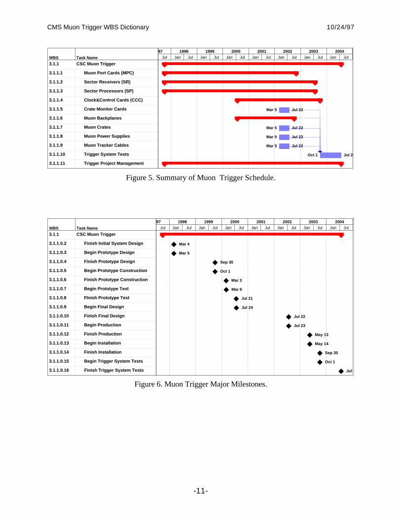
We foresee the development of the Regional Muon Trigger System in four phases. The prototypedesign and production phase will continue through 1999. The final design of the various systemcomponents will continue until 2002. Production will begin in 2001 and end in 2003. Installationand commissioning will begin in 2003 and continue until 2005. The schedule, at its highest level,is shown in Figure 5 and the schedule milestones are summarized in Figure 6.
CMS Muon Trigger WBS Dictionary 10/24/97
-11-
WBS Task Name
3.1.1 CSC Muon Trigger
3.1.1.1 Muon Port Cards (MPC)
3.1.1.2 Sector Receivers (SR)
3.1.1.3 Sector Processors (SP)
3.1.1.4 Clock&Control Cards (CCC)
3.1.1.5 Crate Monitor Cards
3.1.1.6 Muon Backplanes
3.1.1.7 Muon Crates
3.1.1.8 Muon Power Supplies
3.1.1.9 Muon Tracker Cables
3.1.1.10 Trigger System Tests
3.1.1.11 Trigger Project Management
Mar 5 Jul 22
Mar 5 Jul 22
Mar 5 Jul 22
Mar 5 Jul 22
Oct 1 Jul 2
Jul Jan Jul Jan Jul Jan Jul Jan Jul Jan Jul Jan Jul Jan Jul
97 1998 1999 2000 2001 2002 2003 2004
Figure 5. Summary of Muon Trigger Schedule.
WBS Task Name
3.1.1 CSC Muon Trigger
3.1.1.0.2 Finish Initial System Design
3.1.1.0.3 Begin Prototype Design
3.1.1.0.4 Finish Prototype Design
3.1.1.0.5 Begin Prototype Construction
3.1.1.0.6 Finish Prototype Construction
3.1.1.0.7 Begin Prototype Test
3.1.1.0.8 FInish Prototype Test
3.1.1.0.9 Begin Final Design
3.1.1.0.10 Finish Final Design
3.1.1.0.11 Begin Production
3.1.1.0.12 Finish Production
3.1.1.0.13 Begin Installation
3.1.1.0.14 Finish Installation
3.1.1.0.15 Begin Trigger System Tests
3.1.1.0.16 Finish Trigger System Tests
Mar 4
Mar 5
Sep 30
Oct 1
Mar 3
Mar 6
Jul 21
Jul 24
Jul 22
Jul 23
May 13
May 14
Sep 30
Oct 1
Jul
Jul Jan Jul Jan Jul Jan Jul Jan Jul Jan Jul Jan Jul Jan Jul
97 1998 1999 2000 2001 2002 2003 2004
Figure 6. Muon Trigger Major Milestones.

CMS Muon Trigger WBS Dictionary 10/24/97
-12-
5. US RESPONSIBILITY
The US institutions participating in CMS have undertaken the design and building of the RegionalMuon Trigger System. This system begins with the Muon Port Cards which collect data fromfront-end Motherboards on twisted pair cable, and ends with cables that transmit the results to theglobal level 1 muon trigger system. Responsibilities for the front-end signals are also aresponsibility of US groups but are included as a part of the Endcap Muon system budget (US-CMS WBS item 1). Responsibilities for the fiber optics clock and control transmission system, thetrigger interface to DAQ, the Global Muon Trigger, and the Global Level 1 trigger are assigned tonon-US CMS groups.
US Institutions participating in the Regional Muon Trigger:
Institute Contact Person
University of California, Los Angeles J. Hauser
Rice University, Houston P. Padley
CMS Muon Trigger WBS Dictionary 10/24/97
-13-
6. COSTING METHODOLOGY
6.1 Base Cost
The M&S cost for the trigger system was calculated by determining the cost of ASIC's, boards,crates, and cables. The numbers of ASIC's, boards, crates, and cables were determined from thedesign described above.
The EDIA cost for the trigger system was calculated from the EDIA costs already experienced forthe design, manufacture and test of prototypes. The M&S and EDIA calculations also usedinformation from an analysis of the Zeus trigger electronics and the XFT project for the CDFupgrade.
6.2 Contingency
The costs listed in the budget estimate are the base costs of producing each item correctly the firsttime. There are also explicit costs listed for prototyping where required. The cost contingency isthe cost required beyond the base cost to ensure successful completion. The calculation ofcontingency has been done for each WBS item. The calculation of contingency was determinedfrom an analysis of the Zeus trigger electronics and the XFT project for the CDF upgrade. M&Sand Labor costs also took into account the actual experience on these projects before anycontingency was determined. In addition, the prototyping experience on CMS trigger electronicswas also used as input.
Each item is first assigned a contingency of 20% for M&S and 30% for Labor. This was found tobe the appropriate for the most difficult boards in the Zeus trigger system after M&S and Laborcosts were increased to take into account the actual experience on Zeus before any contingency wasdetermined. Each item is then assigned a factor based on the degree of difficulty, where 1.0 wasassigned to difficult items, 0.8 assigned to average items and 0.6 assigned to easy items. Finally,each item was multiplied by a factor corresponding to its maturity of design, where 1.1 is assignedto items taken from a catalog, 1.2 for items where there is a bid package ready to go out or a quote,1.3 where the cost is based on an engineering design, and 1.5 where the cost is based on aconceptual design.

CMS Muon Trigger WBS Dictionary 10/24/97
-14-
7. WBS DICTIONARY AND BASIS OF ESTIMATE
WBS Element: 3.1.1
WBS Element Title: Regional Muon Trigger
WBS Definition:
This WBS element includes all the effort to develop, produce, assemble, install and commissionthe Regional Muon Trigger.
Basis of Estimate:
This element's costs are generated as the sum of lower–level WBS elements.
WBS Element: 3.1.1.1
WBS Element Title: Muon Port Cards (MPC)
WBS Definition:
This WBS element includes all the effort to develop, produce, assemble, install and commissionthe Muon Port Card portion of the Regional Muon Trigger. The system contains 96 of these cardsplus spares.
Basis of Estimate:
This element's costs are generated as the sum of lower–level WBS elements.
WBS Element: 3.1.1.1.1
WBS Element Title: MPC Design
WBS Definition:
This WBS element represents all of the engineering required to design the Muon Port Cards.
Basis of Estimate:
The design engineering is foreseen to proceed in two stages: an initial period in which theinterfaces to Motherboards, Track Processors, and the system clock (TTC) are defined, and aprototype design stage in which these interfaces are realized. The EDIA is based on experiencewith recent track stub finding prototype development for the CMS muon trigger, and comparabletrigger projects in CDF. The logic on the Muon Port Card will be very similar to that on the CSCTrigger Mother Board. This logic for the prototype is being implemented in a standard FPGA.

CMS Muon Trigger WBS Dictionary 10/24/97
-15-
Therefore, this element is rated to be of average difficulty. The maturity is that of a conceptualdesign.
WBS Element: 3.1.1.1.2
WBS Element Title: MPC Prototype Construction
WBS Definition:
This WBS element represents the construction of two MPC prototypes which will be bench-testedas well as installed into a working chain of prototype devices.
Basis of Estimate:
The M&S costs are based on current estimates for active components, primarily FPGA and opticallink devices, and board costs (M&S). A modest amount of EDIA is included for oversight of theconstruction of these prototypes. Since the MPC will be built from standard FPGA’s and/orASIC’s the difficulty is average. The maturity is that of a conceptual design.
WBS Element: 3.1.1.1.3
WBS Element Title: MPC Prototype Test
WBS Definition:
This WBS element represents engineering required for testing of the MPC prototypes.
Basis of Estimate:
The engineering EDIA is based on experience with prototype testing for front-end CSC muontrigger cards. Since the MPC will be built from standard FPGA’s and/or ASIC’s the difficulty isaverage. The maturity is that of a conceptual design.
WBS Element: 3.1.1.1.4
WBS Element Title: MPC ASIC and Board Design
WBS Definition:
This WBS element represents all work required to turn prototype MPC designs into productionversion devices having optimized cost and reliability.
Basis of Estimate:
The cost estimate is based on experience with recent track stub finding prototype development forthe CMS muon trigger, and comparable trigger projects in CDF. Since the MPC will be built fromstandard FPGA’s and/or ASIC’s, the difficulty is average. The maturity is that of a conceptualdesign.

CMS Muon Trigger WBS Dictionary 10/24/97
-16-
WBS Element: 3.1.1.1.5
WBS Element Title: MPC Active Components
WBS Definition:
This WBS element represents the purchase of the active components that are installed on the 96MPC boards required to operate the CSC Muon trigger, not including spares.
Basis of Estimate:
The board costs represent the sum of active components, primarily FPGA devices and ASIC’s,which are similar to those used on the Muon Trigger Motherboards and Glink optical links beingused elsewhere in CMS. We assume 7 Gbaud links are required per MPC. The difficulty isaverage. The maturity is that of a conceptual design.
WBS Element: 3.1.1.1.6
WBS Element Title: MPC Boards
WBS Definition:
This WBS element represents the production of the 96 MPC required to operate the CSC Muontrigger, not including spares. Engineering EDIA is included for management of the production, andtechnician EDIA is included for inspection and testing.
Basis of Estimate:
The board costs represent the sum of board manufacturing costs, plus cables and connectors. TheEDIA is extrapolated from past experience with production of boards for CDF, UA1, KTeV, andother experiments. Since these are standard boards, the difficulty is rated as average. The maturityis that of a conceptual design.
WBS Element: 3.1.1.1.7
WBS Element Title: MPC Installation
WBS Definition:
This WBS element represents the engineering required for proper installation and debugging of theMPC cards in the CMS detector.
Basis of Estimate:
The engineering EDIA required is extrapolated from past experience on CDF, KTeV, and otherexperiments. A considerable fraction of the total effort will be physicist labor paid by the DOE baseprogram. Since the installation will be a standard activity, the difficulty is rated as average. Thematurity is that of a conceptual design.

CMS Muon Trigger WBS Dictionary 10/24/97
-17-
WBS Element: 3.1.1.1.8
WBS Element Title: MPC Spares
WBS Definition:
This WBS element represents the spare cards which are required to ensure a proper level ofoperating reliability.
Basis of Estimate:
The number of spares is determined by using a well-known formula: 10% of the number requiredfor operation, plus two. The spares are costed at the same price as the production units. Thedifficulty is average, as it is for the majority of the MPC system, and the maturity is that of aconceptual design.
WBS Element: 3.1.1.2
WBS Element Title: Sector Receivers (SR)
WBS Definition:
This WBS element represents the design, prototyping, production, assembly, and testing of theSector Receiver cards within the Track Processor crates.
Basis of Estimate:
There are two Sector Receiver cards within each Track Processor crate required for operation of theEndcap Muon Trigger. Each Sector Receiver card receives data on 14 optical fibers from the MuonPort Cards as well as equivalent data from each of two Sector Receiver cards adjacent in phi, andthree equivalent cards within the Barrel Muon Track Processors (to handle rapidity overlap). Thecost estimate per board is comparable to the estimated cost per board ($3220) for the Linker boardof the XFT tracker for the CDF upgrade project. The boards use similar board space and part countfor FPGA and other active components. The logic and function is relatively straightforward andtherefore the difficulty is average. The maturity is that of a conceptual design.
WBS Element: 3.1.1.2.1
WBS Element Title: SR Design
WBS Definition:
This WBS element represents all of the engineering required to design the Sector Receiver Cards.
Basis of Estimate:
The design engineering is foreseen to proceed in two stages: an initial period in which theinterfaces to MPC’s, other SR’s, the Sector Processors (SP) and the system clock (TTC) aredefined, and a prototype design stage in which these interfaces are realized. The EDIA is based oncomparable trigger projects in CDF. This element is rated to be of average difficulty. The maturityis that of a conceptual design.

CMS Muon Trigger WBS Dictionary 10/24/97
-18-
WBS Element: 3.1.1.2.2
WBS Element Title: SR Prototype Construction
WBS Definition:
This WBS element represents the construction of two SR prototypes which will be bench-tested aswell as installed into a working chain of prototype devices.
Basis of Estimate:
The M&S costs are based on current estimates for active components, primarily FPGA and opticallink devices, and board costs (M&S). A modest amount of EDIA is included for oversight of theconstruction of these prototypes. Since the SR will be built from standard FPGA’s and/or ASIC’sthe difficulty is average. The maturity is that of a conceptual design.
WBS Element: 3.1.1.2.3
WBS Element Title: SR Prototype Test
WBS Definition:
This WBS element represents engineering required for testing of the SR prototypes.
Basis of Estimate:
The cost estimate is based on comparable trigger projects in CDF and Zeus. Since the SR will bebuilt from standard FPGA’s and/or ASIC’s, the difficulty is average. The maturity is that of aconceptual design.
WBS Element: 3.1.1.2.4
WBS Element Title: SR ASIC and Board Design
WBS Definition:
This WBS element represents all work required to turn prototype SR designs into productionversion devices having optimized cost and reliability.
Basis of Estimate:
The cost estimate is based on comparable trigger projects in CDF and Zeus. Since the SR will bebuilt from standard FPGA’s and/or ASIC’s, the difficulty is average. The maturity is that of aconceptual design.

CMS Muon Trigger WBS Dictionary 10/24/97
-19-
WBS Element: 3.1.1.2.5
WBS Element Title: SR Active Components
WBS Definition:
This WBS element represents the purchase of the active components that are installed on the SRboards required to operate the CSC Muon trigger, not including spares.
Basis of Estimate:
The board costs represent the sum of active components, primarily FPGA devices and Glinkoptical links. Since high-speed optical fiber receivers will be taken from other CMS designs, thetask difficulty is rated as average. The maturity is that of a conceptual design.
WBS Element: 3.1.1.2.6
WBS Element Title: SR Boards
WBS Definition:
This WBS element represents the production of the SR boards required to operate the CSC Muontrigger, not including spares. Engineering EDIA is included for management of the production, andtechnician EDIA is included for inspection and testing.
Basis of Estimate:
The board costs represent the sum of board manufacturing costs, plus cables and connectors. TheEDIA is extrapolated from past experience with production of boards for CDF, UA1, KTeV, Zeusand other experiments. Since these are standard boards, the difficulty is rated as average. Thematurity is that of a conceptual design.
WBS Element: 3.1.1.2.7
WBS Element Title: SR Installation
WBS Definition:
This WBS element represents the engineering required for proper installation and debugging of theSR Boards in the counting house.
Basis of Estimate:
The engineering EDIA required is extrapolated from past experience on CDF, UA1, KTeV, Zeusand other experiments. A considerable fraction of the total effort will be physicist labor paid by theDOE base program. Since the installation will be a standard activity, the difficulty is rated asaverage. The maturity is that of a conceptual design.

CMS Muon Trigger WBS Dictionary 10/24/97
-20-
WBS Element: 3.1.1.2.8
WBS Element Title: SR Spares
WBS Definition:
This WBS element represents the spare cards which are required to ensure a proper level ofoperating reliability.
Basis of Estimate:
The number of spares is determined by using a well-known formula: 10% of the number requiredfor operation, plus two. The spares are costed at the same price as the production units. Thedifficulty is average, as it is for the majority of the SR system, and the maturity is that of aconceptual design.
WBS Element: 3.1.1.3
WBS Element Title: Sector Processors (SP)
WBS Definition:
This WBS element represents the design, prototyping, production, assembly, and testing of theSector Receiver cards within the Track Processor crates.
Basis of Estimate:
There are three Sector Processor cards within each Track Processor crate required for operation ofthe Endcap Muon Trigger. Each Sector Processor card receives muon stub data over the muonbackplane and looks for tracks using pattern arrays and combinatorial logic. The cost estimate perboard is comparable to the estimated cost per board ($3220) for the Linker board of the XFTtracker for the CDF upgrade project. The boards use similar board space and part count for FPGAand other active components. The interfaces to the SR boards and the Global Muon trigger, as wellas the combinatorics, render this a difficult design.
WBS Element: 3.1.1.3.1
WBS Element Title: SR Design
WBS Definition:
This WBS element represents all of the engineering required to design the Sector Processor Cards.
Basis of Estimate:
The design engineering is foreseen to proceed in two stages: an initial period in which theinterfaces to other SP’s, the Sector Receivers (SR) and the system clock (TTC) are defined, and aprototype design stage in which these interfaces are realized. The EDIA is based on comparabletrigger projects in CDF. This element is rated to be difficult. The maturity is that of a conceptualdesign.

CMS Muon Trigger WBS Dictionary 10/24/97
-21-
WBS Element: 3.1.1.3.2
WBS Element Title: SP Prototype Construction
WBS Definition:
This WBS element represents the construction of two SP prototypes which will be bench-tested aswell as installed into a working chain of prototype devices.
Basis of Estimate:
The M&S costs are based on current estimates for active components, primarily FPGA and opticallink devices, and board costs (M&S). A modest amount of EDIA is included for oversight of theconstruction of these prototypes. This element is rated to be difficult. The maturity is that of aconceptual design.
WBS Element: 3.1.1.3.3
WBS Element Title: SR Prototype Test
WBS Definition:
This WBS element represents engineering required for testing of the SP prototypes.
Basis of Estimate:
The cost estimate is based on comparable trigger projects in CDF and Zeus. This element is rated tobe difficult. The maturity is that of a conceptual design.
WBS Element: 3.1.1.3.4
WBS Element Title: SP ASIC and Board Design
WBS Definition:
This WBS element represents all work required to turn prototype SP designs into productionversion devices having optimized cost and reliability.
Basis of Estimate:
The cost estimate is based on comparable trigger projects in CDF and Zeus. This element is rated tobe difficult. The maturity is that of a conceptual design.

CMS Muon Trigger WBS Dictionary 10/24/97
-22-
WBS Element: 3.1.1.3.5
WBS Element Title: SP Active Components
WBS Definition:
This WBS element represents the purchase of the active components that are installed on the SPboards required to operate the CSC Muon trigger, not including spares.
Basis of Estimate:
The board costs represent the sum of active components, primarily FPGA devices and ASIC’s.This element is rated to be difficult. The maturity is that of a conceptual design.
WBS Element: 3.1.1.3.6
WBS Element Title: SP Boards
WBS Definition:
This WBS element represents the production of the SP boards required to operate the CSC Muontrigger, not including spares. Engineering EDIA is included for management of the production, andtechnician EDIA is included for inspection and testing.
Basis of Estimate:
The board costs represent the sum of board manufacturing costs, plus connectors. The EDIA isextrapolated from past experience with production of boards for CDF, UA1, KTeV, Zeus andother experiments. This element is rated to be difficult. The maturity is that of a conceptual design.
WBS Element: 3.1.1.3.7
WBS Element Title: SP Installation
WBS Definition:
This WBS element represents the engineering required for proper installation and debugging of theSP Boards in the counting house.
Basis of Estimate:
The engineering EDIA required is extrapolated from past experience on CDF, UA1, KTeV, Zeusand other experiments. A considerable fraction of the total effort will be physicist labor paid by theDOE base program. Since the installation will be a standard activity, the difficulty is rated asaverage. The maturity is that of a conceptual design.

CMS Muon Trigger WBS Dictionary 10/24/97
-23-
WBS Element: 3.1.1.3.8
WBS Element Title: SP Spares
WBS Definition:
This WBS element represents the spare cards which are required to ensure a proper level ofoperating reliability.
Basis of Estimate:
The number of spares is determined by using a well-known formula: 10% of the number requiredfor operation, plus two. This element is rated to be difficult. The maturity is that of a conceptualdesign.
WBS Element: 3.1.1.4
WBS Element Title: Clock & Control Card (CCC)
WBS Definition:
This WBS element includes all the effort to develop, produce, assemble, install and test theRegional Muon Trigger Clock and Control Card (CCC). This card receives, aligns and logs theclock and control signals and distributes them with adjustable delays along individual lines to eachof the cards in the Track Processor trigger crate.
Basis of Estimate:
The M&S and EDIA is based on boards built for the Zeus calorimeter trigger system, and checkedagainst the full-size CMS prototype calorimeter trigger Clock and Control Card already constructedand tested. Since the board will be adapted from the design of the CMS calorimeter trigger Clockand Control Card, the task is rated as easy. Since similar prototype boards already exist, thematurity is that of an engineering design.
WBS Element: 3.1.1.4.1
WBS Element Title: CCC Board Design
WBS Definition:
This WBS element represents all of the engineering required to design the CCC Boards.
Basis of Estimate:
The cost is based on comparable trigger projects in CDF and Zeus. It is checked against the full-size CMS prototype calorimeter trigger Clock and Control Card already constructed and tested.This task is rated as easy. The maturity is that of an engineering design.

CMS Muon Trigger WBS Dictionary 10/24/97
-24-
WBS Element: 3.1.1.4.2
WBS Element Title: CCC Active Components
WBS Definition:
This WBS element represents the purchase of the active components that are installed on the CCCboards required to operate the CSC Muon trigger, not including spares.
Basis of Estimate:
The cost is based on comparable trigger projects in CDF and Zeus. It is checked against the full-size CMS prototype calorimeter trigger Clock and Control Card already constructed and tested.This task is rated as easy. The maturity is that of an engineering design.
WBS Element: 3.1.1.4.3
WBS Element Title: CCC Boards
WBS Definition:
This WBS element represents the production of the CCC boards required to operate the CSC Muontrigger, not including spares. Engineering EDIA is included for management of the production, andtechnician EDIA is included for inspection and testing.
Basis of Estimate:
The cost is based on comparable trigger projects in CDF and Zeus. It is checked against the full-size CMS prototype calorimeter trigger Clock and Control Card already constructed and tested.This task is rated as easy. The maturity is that of an engineering design.
WBS Element: 3.1.1.4.4
WBS Element Title: CCC Installation
WBS Definition:
This WBS element represents the engineering required for proper installation and debugging of theSR Boards in the counting house.
Basis of Estimate:
The engineering EDIA required is extrapolated from past experience on comparable triggerprojects in CDF and Zeus. A considerable fraction of the total effort will be physicist labor paid bythe DOE base program. The cost is checked against that required for the full-size CMS prototypecalorimeter trigger Clock and Control Card already constructed and tested. This task is rated aseasy. The maturity is that of an engineering design.

CMS Muon Trigger WBS Dictionary 10/24/97
-25-
WBS Element: 3.1.1.4.5
WBS Element Title: CCC Spares
WBS Definition:
This WBS element represents the spare cards which are required to ensure a proper level ofoperating reliability.
Basis of Estimate:
The number of spares is determined by using a well-known formula: 10% of the number requiredfor operation, plus two. This task is rated as easy. The maturity is that of an engineering design.
WBS Element: 3.1.1.5
WBS Element Title: Crate Monitor Card
WBS Definition:
This WBS element includes all the effort to develop, produce, assemble, install and test theRegional Muon Trigger Crate Monitor Card. This card receives, checks and logs voltages andtemperatures in the Muon Trigger Crates.
Basis of Estimate:
The M&S and EDIA is based on boards used in the Zeus calorimeter trigger system, and in othercrate systems. This task is rated as easy. The maturity is that of an engineering design
WBS Element: 3.1.1.6
WBS Element Title: Muon Backplanes
WBS Definition:
This WBS element includes all the effort to develop, produce, assemble, install and test TrackProcessor Trigger Backplanes. The backplane is a monolithic, custom, 9U high printed circuitboard with front and back card connectors. The top 3U of the backplane holds 4 row (128 pin)DIN connectors, capable of full 32 bit VME. The first two front slots of the backplane will,however, use three row (96 pin) DIN connectors in the P1 and P2 positions with the standardVME pinout. The bottom 6U of the backplane, in the data processing section of the crate, utilizes asingle high speed, controlled impedance, connector for both front and rear insertion at each cardposition. The design is based around a 340 pin connector, by AMP Inc, to handle the high volumeof data transmitted from the Sector Receiver cards to the Sector Processor Cards.
Basis of Estimate:
Both M&S and EDIA costs are based on the full-size prototype backplane already constructed andtested for the CMS calorimeter trigger. The task difficulty is rated as average. The design maturityis that of an engineering design.

CMS Muon Trigger WBS Dictionary 10/24/97
-26-
WBS Element: 3.1.1.6.1
WBS Element Title: Muon Backplane Design
WBS Definition:
This WBS element represents all of the engineering required to design the Muon TriggerBackplanes.
Basis of Estimate:
The EDIA costs are based on the full-size prototype backplane already constructed and tested forthe CMS calorimeter trigger. The task difficulty is rated as average. The design maturity is that ofan engineering design.
WBS Element: 3.1.1.6.2
WBS Element Title: Muon Backplane Procure
WBS Definition:
This WBS element represents all of the M&S required to procure the Muon Trigger Backplanes.
Basis of Estimate:
The M&S costs are based on the full-size prototype backplane already constructed and tested forthe CMS calorimeter trigger. The task difficulty is rated as average. The design maturity is that ofan engineering design.
WBS Element: 3.1.1.7
WBS Element Title: Muon Crates
WBS Definition:
This WBS element includes all the effort to procure, install and test the Track Processor TriggerCrates. The crate is based on standard Eurocard hardware with custom fittings. The height is 9Uand the depth approximately 700mm, as determined by the front and rear card insertion. It requiresa rack 900mm deep to handle the crate depth with some reserve for cabling, plumbing, and otherservices. The front section of the crate is designed to accommodate 280mm deep cards, leaving themajor portion of the volume for 400mm deep rear mounted cards.
Basis of Estimate:
The cost is based on the full-size prototype CMS calorimeter trigger Crate already constructed andtested. The task is easy. The items will be ordered from a catalog.

CMS Muon Trigger WBS Dictionary 10/24/97
-27-
WBS Element: 3.1.1.8
WBS Element Title: Muon Power Supplies
WBS Definition:
This WBS element includes all the effort to procure, install and test the Muon Trigger TrackProcessor crate power supplies.
Basis of Estimate:
The cost is based on the power supplies purchased for the prototype Regional Calorimeter TriggerCrate. The task is easy. The items will be ordered from a catalog.
WBS Element: 3.1.1.9
WBS Element Title: Muon Tracker Cables
WBS Definition:
This WBS element includes all the effort to procure, install and test the Track Processor TriggerCables. Each Receiver card sends some of its data off crate at 40 MHz to two neighboring crates.In addition, each Receiver gets data from three Barrel Track Finder crates. The 24 crates arelocated in pairs in a row of 12 adjacent racks. Crate to crate communication is handled by specialcables running between the Receiver cards. The maximum amount of information shared betweentwo Receiver cards in different crates is carried on 204 twisted pair (102 in each direction) at 40MHz. Special LVDS drivers/receivers may increase this to 140 MHz effective transmission rate pertwisted pair.
Basis of Estimate:
The amount of cable is based on the number of interchanged signals and the crate layout in theracks in the electronics barracks. The cost for the cable is based on the cost for halogen free twistand flat differential-pair signal cable that carried signals at the same frequency for the Zeus triggersystem. The task is easy. The items will be ordered from a catalog.
WBS Element: 3.1.1.10
WBS Element Title: Trigger System Tests
WBS Definition:
This WBS element represents engineering required during installation and debugging in order tosuccessfully commission the Muon Trigger.
Basis of Estimate:
The engineering experiments. EDIA required is extrapolated from past experience on CDF, KTeV,and other A considerable fraction of the total effort will be physicist labor paid by the DOE baseprogram. It is also assumed that prior to the system-wide tests, the prototype versions will havebeen thoroughly tested in the U.S. together with front-end Endcap Muon motherboards and othertrigger boards. The task difficulty is average. The cost is based on a conceptual design.
CMS Muon Trigger WBS Dictionary 10/24/97
-28-
WBS Element: 3.1.1.11
WBS Element Title: Trigger Project Management
WBS Definition:
This WBS element includes all the effort to provide project management of the Muon Triggerproject.
Basis of Estimate:
The effort involved is based on the Project Management of the Zeus Calorimeter System and theSDC Trigger System. The required 5% of an FTE engineer is provided by the UCLA baseprogram and therefore there is no cost to the US CMS project.
WBS Element: 3.1.1.11.1
WBS Element Title: Tracking and Reporting
WBS Definition:
This WBS element includes all the effort to provide tracking and reporting of the Muon Triggerproject.
Basis of Estimate:
The effort involved is based on the tracking and rreporting of the Zeus Calorimeter System and theSDC Trigger System. The required 5% of an FTE engineer is provided by the UCLA baseprogram and therefore there is no cost to the US CMS project.