Embed Size (px)
Citation preview
Water Mist Protection of Combustion Turbine Enclosures
Robert G. Bill, Jr. and Erdem A. Ural* Factory Mutual Research Corporation 1 15 1 Boston-Providence Turnpike Norwood, Massachusetts 02062
*Currently with Fenwal Safety Systems A Division of Kidde Technologies 700 Nickerson Road Marlborough, MA 01752
ABSTRACT
Loss experience for combustion turbine enclosures and the need to find alternatives to halon protection have led to the development of a fire test methodology to evaluate the effectiveness of water mist systems for this occupancy. The fire test methodology is used to determine the capability of water mist systems to extinguish fires resulting from diesel. hydraulic, or lubrication oil pool or spray fires which have been identified as the most likely fire scenarios. In addition. a water mist cooling test has been developed to determine whether turbine casing deformation resulting from spray cooling is acceptable. Results from the fire test methodologies are given for a water mist system protecting a simulated 80 m' turbine enclosure.
KEYWORDS: water mist, fine water spray, combustion turbines, flammable liquid hazards
INTRODUCTION
Combustion turbine enclosures along with associated cornpartlnents such as the generator room, load tunnel, and accessory compartments (with various pumps, gearboxes. and starter motors) are protected with a variety of fire protection systems. These systems include total flooding gaseous agents (typically halon or carbon dioxide), sprinkler systems, high expansion foam, and manual methods, including hose streams and dry chemical portable extinguishers [1.2,3]. Dundas [3] reviewed sixty-four fire losses in combustion turbine enclosure installations and reported a forty-nine percent failure rate for total flooding halon or carbon dioxide systems in thirty-nine fire incidents. In eleven events where portable dry chemical extinguishers were used the failure rate was forty-five percent.
FIRE SAFETY SrlENCE-PaOCEEDNC-S CIC T Y E SIX-H INTERNATIONAL SYVPOSIUM pp $57-468
Copyright © International Association for Fire Safety Science
Commenting on the high failure rate of total flooding systems. Dundas concluded that the most likely cause of failure was leakage of the agent through open doors or vents. In the case of sprinklers, the system is designed for cooling rather than extinguishment. Gustatson [4] demonstrated that oil spray fires can not typically be extinguished by sprinkler or deluge systems except under special circumstances and with very high sprinkler discharge densities. A problem associated with water spray systems, which have been improperly installed. is the potential for deformation of the turbine casing and resulting turbine blade rubbing due to rapid cooling of the turbine casing by water spray.
Protection of combustion turbine enclosures by water mist' systems was. therefore, sought. In part, due to the phasing out of halon. In extensive tests. Wighus et ai [6] showed that diesel pool and spray fires, the primary hazards for combustion turbine enclosures. could be extinguished using water mist. Tests were carried out in compartments 30 m' and 70 m3 in volume. The 70 mi contained a mock-up of a turbine heated internally to simulate hot metal surfaces with insulation mats and piping as in a real turbine casing. In addition to demonstrating the capabilities of water mist systems to extinguish oil spray and pool fires. Wighus et al [6] showed that stabilized propane jet fires w~th a heat release rate of about 1 MW were easily extinguished. The main conclusions of the study were. "The water mist system [used in the study] is very effective in extinguishing big fires [ > I MW]": "ventilation controlled fires are easily extinguished by the water mist system"; and "small fires are difficult to extinguish with the water mist system, except when the spray directly hits the fire base." Based on these promising results, FMRC decided in 1993 to proceed to develop a fire test methodology to allow water mist systems to be FMRC Approved for the protection of combustion turbine enclosures and machinery spaces.
The mechanisms by which water mist systems extinguish fires are generally agreed upon, although as indicated in the National Fire Protection Association (NFPA) Water Mist Standard (NFPA 750) [ 7 ] , "Currently, no generally design method is recognized for water mist protection systems." Mawhinney, Dlugogorski and Kim [8] state that the major extinguishment mechanisms are heat extraction, oxygen displacement and blocking of radiant heat. This is similar to Wighus' [9] view that water mist systems extinguish through a combination of oxygen depletion by production of steam and cooling by the evaporation of water. These mechanisms are consistent with the long recognized concept, (see e.g., Reference 10) that small water droplets could be entrained into the fire. producing cooling and oxygen dilution in the combustion zone. Another consideration in the performance of water mist systems is the oxygen consumption by the fire during the period of extinguishment. Bill et al [I I ] observed in simulated engine room fire tests with flammable liquids that extinguishment did not occur unless the compartment oxygen concentration was reduced to about seventeen percent. Indeed, in uncompartrnented fire tests within the FMRC Test Center, extinguishment of flammable liquid fires did not occur. In general. the complex nature of the delivery of water mist to the combustion zone is primarily responsible for the
' Fine water spray would seem to be a more apprcpl-iate term than mist since the term mist ih used with watei- droplets that are much sinaller than thosc generated by current commercial s y a t e m hi- h ie protection Foi example, Reference 5 indicates that drop sizes of mists range from 0.01 to 10 micron,: while droplcts for spraya range from I0 to 3000 microns. a range that cncompasscs cul.rcnt waler "niist" technology.
difficulty in developing design criteria for water mist systems and the need to depend upon fire testing.
PERFORMANCE OBJECTIVES
Fire Extinguishment Capabilities
The initial performance objective of the water mist system established at FMRC was to provide fire extinguishment capabilities equivalent to that provided by gaseous systems under ideal conditions while removing the characteristics of these systems which result In the high failure rates cited above. Gaseous systems, such as halon or carbon dioxide, will extinguish all fires within a compartment assuming that the design concentration is maintained. In order to maintain the design concentration, interlocks to close all doors at the time of fire detection are required. Another feature of combustion turbine protection systems is that the fuel is shut off at the time of detection and the turbine is allowed to coast to a halt. During this time. lubrication oil must be maintained to avoid damage to the bearings and the turbine. For this reason, the design concentration of a gaseous system must be maintained at least for the duration of coast down. In addition, because of the low cooling by the gaseous agent of the turbine casing and other components, the possibility exists for re-ignition due to hot surfaces. if the design concentration is lost. A typical protection time afforded by a gaseous system is about twenty minutes. [I21 In the case of water mist, the system is only effective during discharge; hence, a water supply sufficient to cover the coast down time of the turbine is required. The discharge time for extinguishment by water mist is relatively short: hence, additional system discharges are available if detection indicates that the fire has not been extinguished or re-ignites.
Differences between water mist and gaseous systems resulted in modifications in the performance objective. While gaseous agents can, in principle, extinguish fires of any size within a closed compartment once the design concentration has been achieved, i t has been observed that water mist systems have difficulty in extinguishing small fires compared to larger fires. This phenomenon has been observed in fire tests with flammable liquids such as those reported by Wighus [6] and Bill, et al [I I ] . Presumably, the larger f~res, more effectively convert the water mist into steam and. therefore, generate more steam to inert the fire and cool the combustion zone of flames. For example, Bill et a1 [I I] tested a water mist system installed in a compartment about 1000 m' in volume in which a 6 MW diesel oil spray fire was extinguished, whereas, a I MW spray fire under the same test conditions was not.
It is difficult after fire events to estimate maximum heat release rates: however. FMRC loss experience indicates that fires in combustion turbine enclosures are expected to be in excess of 1 MW due to release of lubrication oils and hydraulic fluids. Somewhat arbitrarily, therefore, it was decided to select spray and pool diesel oil fires with heat release rates of about 1 MW as the minimum fire size to test water mist systems, the expectation being that larger fires would occur in practice. All fires described in this paper must be extinguished in order for a water mist system to receive FMRC approval. Of interest is the authors' observation, that it was possible to manually extinguish a 1 MW spray diesel oil fire using a carbon dioxide hand held extinguisher.
Another characteristic of combustion turbine enclosure fires is the extreme shielding that results from the complexity of the various oil lines and components in the combustion turbine enclosure. This is not a problem with gaseous agents; however, the tests by Wighus, et a1 [6] indicated that fire extinguishment without direct water spray impingement was difficult. For this reason, it was decided that test fires would include scenarios where spray or pool fires were shielded such that the water mist could not directly impinge on the fire source. Extinguishment would therefore demonstrate that the fine droplets were effective as a result of entrainment into the fire.
In addition to the complexity of equipment leading to shielded fires, i t was also felt that the location of the fire could not be pre-determined; hence. water mist systems were to be specified in terms of uniform nozzle spacings rather than by selected local application. Note that in comparison, total flooding gaseous systems are less sensitive to either shielding or fire location.
Although water mist systems do not seem capable of extinguishing all size fires, it was felt that, unlike total flooding gaseous system, they would be capable of extinguishing large fires even under conditions of limited ventilation, such as an open man-door. Because this appears to be the greatest cause of failure of gaseous systems. this would result in a significant advantage for water mist protection for this application. The implementation of this fire test requirement for water mist systems is discussed below. Because water mist systems remain an emerging technology for which there is no detailed design method, water mist systems are still required to have interlocks to shut off ventilation and close doors upon actuation of smoke detectors. The ability for these systems to perform successfully, therefore, represents a safety factor.
Impact of Water mist Cooling on Deformation of Hot Turbine Casings
As noted by Hathaway [ I ] . the impact of water spray on hot turbine casing is controversial. Loss experience at FMRC is unfortunately inconclusive in regard to the effect of water on hot turbine casings. In one incident, a six-inch sprinkler riser, supplying automatic sprinkler protection over a 35 MW combustion turbine generator (Westinghouse model W-251-B). separated at the flexible coupling at roof level. Water discharged on the combustion turbine, which was in operation at the time, soaking its insulation blankets and its associated switchgear. The unit tripped off line and came to a stop in about five minutes (normal coastdown is around fifteen minutes). It seized and attempts to put i t on turning gear failed. After cooling a few days, the unit was manually rotated, with no sign of internal damage. The keyway between the turning gear motor and the drive gear was damaged. Once this was repaired, the unit was put on turning gear, and it was subsequently returned to operation. No evaluation was made of the unit's efficiency; however, water impingement was substantially greater than would be expected from an operating sprinkler or water spray system and no damage was reported.
In another incident, a deluge system accidentally operated three times, spraying water onto the hot casing of an 18 MW (GE model Series 5000, Frame 5) simple cycle, single shaft combustion turbine. Following each incident, operators inspected the turbine and noted no vibration or unusual noises; however, in each case increased exhaust temperatures were noted and efficiency decreased. It was not possible to determine if damage occurred without
dismantling the turbine, which was not done due to production requirements. It is estimated that the water spray density on the turbine was substantially more than 8 mmlmin (0.2 gpm/ft', the minimum recommended by FMRC for lubrication oil systems. This densit!) would appear therefore to represent a threshold value for which water spray might begin to cause damage.
Based upon the events discussed above, i t appears that the impingement of water on a turbine casing in a normal sprinkler discharge is unlikely to cause stress beyond the yield point of the turbine casing material. In contrast, de Ris [I 31 inferred that deformation of the turbine casing could cause a problem with turbine blade rubbing due to the decrease in clearance between the casing and turbine blades. De Ris estimated the deformation by approximating the turbine casing as a thin walled cylinder maintained at a constant temperature on its inner wall and cooled non-uniformly by sprinkler spray on the outer surface. Assuming, that only circumferential (hoop) stresses were thermally induced, the general thermal stress-strain relation (see e.g., Reference 14) holding throughout the hoop is:
where, a , is the coefficient of thermal expansion, E (s.z) is the strain at a distance s along
the hoop centerline and the normal distance z from the centerline. o ( 3 , : ) is the
circumferential stress, and E is Young's modulus. Initially, the hoop is circular and unstressed at the reference temperature, To. After the outer surface has been cooled by water
spray, the temperature distribution in the hoop is T(s.2).
Because the turbine casing was approximated as a thin walled cylinder, de Ris calculated the strain applying simple bean1 theory in a straight-forward manner (see e.g.. Reference 14) and assuming uniform properties, i.e.:
Here, E , , is the mean strain, and the local deflection angle is $(s)
For non-uniform cooling, the hoop can, in principle, sustain a local shear force, tension, and bending moment. De Ris [I31 obtained from an evaluation of the forces and moments at a cut of the hoop as a free-body, a differential equation relating the deflection angle to the moment and temperature distribution (see e.g. Reference 14). In this equation, the moment distribution was determined from the tension and shear forces, which were obtained from the continuity of the deflection angle and by assuming that the transverse deflection of the hoop is zero at the hoop diameter in the horizontal plane. The deflection angle was then determined for a glven temperature distribution.
The deflection at a point s, along the circumference of the hoop. can be determined from the integrated effect of the changing deflection angle,@. For a spray distribution consisting of four sprays, each covering an angle of 45", distributed symmetrically around a hoop of radius
R and thickness, 6. de Ris [I31 found that the maximum radial deflection.AR . including max
mean shrinkage is:
with
12 a - 1 " 2 g = -T (s); T ( s ) = - I : ( T ( s , z ) - 7',,)(1:
6 6 - - s , 2
and
The maximum deflection, given in Equation 3, is greater than the shrinkage caused by uniform cooling. By way of comparison, water sprays providing uniform cooling would minimize the possibility of blade rubbing; however, a uniform spray is not likely to be achievable due to spatial variations in the spray, equipment shielding the turbine, and limitations on placement of spray nozzles around the turbine. The maximum deflection. given in Equation 3 is considered to represent an achievable level of deflection in the sense that allowance is made for sections where cooling does not occur. Note that in practice, i t is likely that some cooling would occur over the entire casing (i.e., there would be no dry spots) and the deflection would be less than that predicted by Equation 3. De Ris has shown that other patterns of cooling can result in greater maximum deflections as the patterns differ more widely from approximating uniform cooling. It is assumed in this study that the allowable deflection due to cooling is proportional to the radius of the turbine casing for all classes of combustion turbines. A representative value of the clearance between the casing and the turbine blades is about 0.1% of the casing radius, when the turbine is under load [ I 51. At shut down, the clearance rapidly increases, doubling in about five minutes [15]. For a given temperature distribution within a turbine casing during cooling. Equation 3 can be used to determine if AR
max ' Rturbine 5 0.001 .
EXPERIMENTAL METHODS
Test Facilities
Fire testing for FMRC Approval of combustion turbine enclosures and machinery spaces has been conducted at the FMRC Test Center in West Glocester, RI. Tests have been conducted under the 18 m high ceiling for an enclosure 80 m3 In volume. shown in Figure 1 . The dimensions of the enclosure were selected to be representative of an intermediate-size combustion turbine enclosure. Note that FMRC approval is limited to the dimensions of the enclosure in which testing occurs. The dimensions of the enclosure are selected by the water mist system manufacturer with the turbine mock-up sized appropriately. A door was installed along one wall to provide natural draft in some fire tests. Four hatches were installed on the ceiling to ventilate the enclosure after fire tests. A horizontal A36 steel plate. 1.0 In x 2.0 m x 0.05 m thick, simulating the cross section and thermal properties of a typical turbine casing.
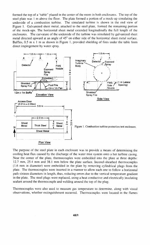
formed the top of a "table" placed in the center of the room in both enclosures. The top of the steel plate was 1 m above the floor. The plate formed a portion of a mock-up simulating the underside of a combustion turbine. The simulated turbine is shown in the end view of Figure 1 . Galvanized sheet metal, attached to the steel plate, formed the remaining portion of the mock-ups. The horizontal sheet metal extended longitudinally the full length of the enclosures. The curvature of the underside of the turbine was simulated by galvanized sheet metal directed upward at an angle of 45" on either side of the horizontal sheet metal surface. Baffles. 0.5 m x 1 m as shown in Figure I . provided shielding of fires under the table from direct impingement by water spray.
I I
Elevation Vtew Spray Fire
Side View
I Sheet Metal
I
- -
Plan V ~ e w
Sheet , Metal
The purpose of the steel plate in each enclosure was to provide a means of determining the cooling heat flux caused by the discharge of the water mist system onto a hot turbine casing. Near the center of the plate, thermocouples were embedded into the plate at three depths: 12.7 mm, 25.4 nim and 38.1 mm below the plate surface. Inconel-sheathed thermocouples (1.6 mm in diameter) were embedded in the plate by removing cylindrical plugs from the plate. The thermocouples were inserted in a manner to allow each one to follow a horizontal path sixteen diameters in length, thus, reducing errors due to the \,ertical temperature gradient in the plate. The steel plugs were replaced, using a heat conductive and electrically insulating sealant around the thermocouple and welding around the top of the plug.
Thermocouples were also used to measure gas temperature to determine. along with visual observations, whether extinguishment occurred. Thermocouples were located in the flames
Thlck Steel
I E : Sheet W - Metal 1 * I 1 Flgure 1 Cotnbust~on tclrb~ne plotection test enclosme
and in the entrained airflow. These were bare bead thermocouples welded from 28 gauge chromel-alumel wire.
Concentrations of oxygen, obtained with a paramagnetic analyzer. were measured on a dry basis; i.e., after water vapor was removed from the gas, using gas sampling near the locat~on of the entrained air thermocouple. An analysis of gas concentrations, using carbon dioxide and carbon monoxide concentration measurements with a simple chemistry model. indicated that oxygen results were accurate to about 1%. The gas sampling occul.red at the same elevation as the entrained air thermocouple, but sufficiently far, so that the oxygen measurements were not affected by [he flames. Oxygen concentrations were measured to determine if sufficient oxygen were available to sustain combustion.
Water supply pressures and air supply pressures for the air atomized. water mi\t syjtem were monitored using strain gauge pressure transducers. All data from the various instrumentation channels were acquired at a rate of I scan per second using computerized data acquisition.
Fire Sources
The most hazardous fire scenarios for combustion turbine enclosures. identified in Reference 3, are diesel pool fires and diesel spray fires resulting from the fracture of diesel fuel I~nes. Based on these considerations, the following diesel fuel fires sources were selected for the FMRC extinguishment tests: square diesel oil pool fires 1 m2 in area, and diesel oil spray fires with heat release rates of 1.0 MW, and 2.0 MW. In order to accurately determine the heat release rates of the pool f~res, and to determine the required operating pressures of commercial oil burner nozzles, the test fires were ignited under a Fire Products Coilector (FPC) at the FMRC Test Center in West Glocester, Rhode Island.
The diesel spray fires were generated by two commercial nozzles of the full-cone 80" $pray- angle type. The nozzles were rated for the following flow rates at an operating preicure of 689 kPa: 1.5 1 Ipm, and 3.15 lpm. Operating at 862 kPa, the nozzles provided the required heat release rates of 1 and 2 MW.
In preliminary trials of the diesel spray sources, i t was not possible to stabilize the flame downstream of the nozzles. However, stabilization was obtained by placing the spray nozzle in the center of the bottom of a steel cylindrical container. The diameter of the container was 15.2 cm and the length was 7.6 cm. This configuration provided good stabilization when the nozzles were in the horizontal position.
Water Mist System
The first water mist system tested at FMRC was the Fine Water Spray (FWS) System of Securiplex, Inc. [I61 The system uses air atomized nozzles at a nominal operating pressure of 586 kPa and a nozzle flow rate of 5 Ipm. The median volumetric drop size, on the nozzle axis, 1 m below the nozzle was 98 microns, with 10% of the volume flow ashoc~ated with droplets less than 52 microns and 10% with droplets greater than 165 microns. The placement of the nozzles is shown in Figure 1 . The side nozzles had a nominal longitudinal spacing of Im and the ceiling nozzles, a spacing of 1.9 m. The system operates intermittently with a cycle in which water flows for 20 s followed by a 20 s interruption and another 20 s of
flow. The Securiplex System has been shown in testing for the U.S. Army to provide performance typical of current commercial water mists systems [ 171.
DESCRIPTION OF TESTING
Fire Tests
This section describes the fire tests used to assure the performance objectives described in Section 2. Full details, including variations associated with testing in a 260 in' enclosure, are given in the FMRC Approval Fire Test Standard for Protection of Combustion Turbines and Machinery Spaces (Class 5560) 1181. In the fire tests. the water mist system was actuated by a heat detector on the ceiling (Figure 1 ) with a temperature rating of 88" C, about 70" C above the initial ambient temperature. Heat detectors. therefore, are installed in FMRC Approved installations where high temperatures exist using heat detectors with a temperature rating about 70" C above ambient conditions. Spray fires were used in three different configurations in the combustion turbine enclosure fire testing: shielded spray fire, shielded spray fire with the enclosure door open (see Figure I for door position), and an exposed spray fire. The shielded diesel spray fire was directed along the longitudinal (horizontal) centerline of the combustion turbine mock-up under the steel table shown in Figure 1 ) . The spray fire stabilizer was located 1.8 m from the west wall of the enclosure, that is, at the west edge of the steel table. The fuel spray nozzle was oriented so that the fuel spray flowed from west to east. In addition to the shielding created by the can stabilizer, sheet metal baffles, 0.5 m wide and Im high, were placed in front of the table as shown in Figure 1 , extending the 1 m distance to the floor, to provide shielding in the region of flame stabilization. When tests were conducted with the 1 MW diesel spray fires spray fires, the door to the enclosure and all hatches were closed. When the 2 MW diesel spray fires were used the door to the enclosure was open. A fully exposed spray fire was located 3 m above the floor and over turbine mock-up, as shown in Figure I. The 1 in' diesel pool fires were conducted with the pan on the floor centered under the steel table. The 0.5 m2 baffles (Figure 1 ) were moved so that the edge of the baffles aligned with the edge of the pan, thereby shielding half of the pan.
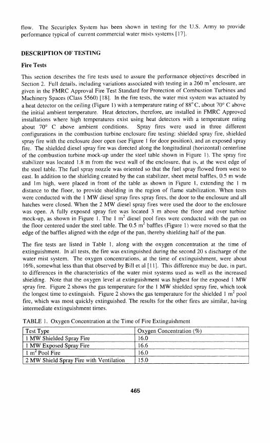
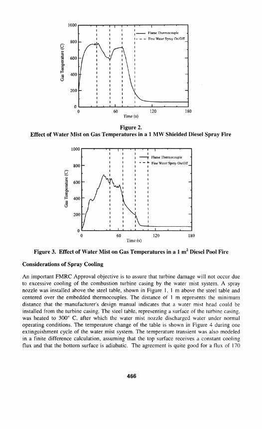
The fire tests are listed in Table 1 , along with the oxygen concentration at the time of extinguishment. In all tests, the fire was extinguished during the second 20 s discharge of the water mist system. The oxygen concentrations. at the time of extinguishment. were about 16%, somewhat less than that observed by Bill et a1 [I 11. This difference may be due, in part. to differences in the characteristics of the water mist systems used as well as the increased shielding. Note that the oxygen level at extinguishment was highest for the exposed 1 MW spray fire. Figure 2 shows the gas temperature for the 1 MW shielded spray fire, which took the longest time to extinguish. Figure 2 shows the gas temperature for the shielded 1 m2 pool fire, which was most quickly extinguished. The results for the other fires are similar, having intermediate extinguishment times.
TABLE 1. Oxygen Concentration at the Time of Fire Extinguishment
/ Test Type 1 Oxygen Concentration (9%) -1 1 MW Shielded Spray Fire 1 MW Exposed Spray Fire 1 m2 Pool Fire 2 MW Shield Spray Fire with Ventilation
16.0 16.6 16.0 15.0
1000
800 ,-. Y E a 600
E F 3 400 0
200 I l l I l l
0 0 60 120 180
'l'ime (s)
Figure 2. Effect of Water Mist on Gas Temperatures in a 1 MW Shielded Diesel Spray Fire
0 60 120 180 Time (s)
Figure 3. Effect of Water Mist on Gas Temperatures in a 1 rnZ Diesel Pool Fire
Considerations of Spray Cooling
An important FMRC Approval objective is to assure that turbine damage will not occur due tc excessive cooling of the combustion turbine casing by the water mist system. A spray nozzle was installed above the steel table, shown in Figure I , 1 m above the steel table and centered over the embedded thermocouples. The distance of 1 m represents the minimum distance that the manufacturer's design manual indicates that a hater mist head cculd be installed from the turbine casing. The steel table, representing a surface of the turbine casing. was heated to 300' C, a f t e ~ which the water mist nozzle discharged water under normal operating conditions. The temperature change of the table is shown in Figure 4 during one extinguishment cycle of the water mist system. The temperature transient was also modeled in a finite difference calculation. assuming that the top surface receives a constant cooling flux and that the bottom surface is adiabatic. The agreement is quite good for a flux of 170
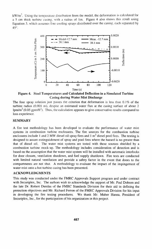
k ~ l m ' . Using the tempcratui-c dislrlhut~on from the model, the defol-mation 15 calculated foi- a 5 cm thick turbine caalng. \\ith a I-adius of lm. Figure 4 also shows this result using Equat~on 3. whicll a\\ume.; f ~ l i i - cooiinf sprays distributed over the casing. each separated by 45".
400 0.0020 - n - C-
$ 300 - 0.0010 C - v - ,- ..2 - U C v' .- .C 200 0.0000 $ - C: 2 B D 2 100 -0.0010
z c
0 -0.0020 0 20 40 60 80 100 120
Time (s)
Figure 4. Steel l'enlperatures and Calculated Deflection in a Simulated Turbine Casing during Water Mist Discharge
The four spray solution just passes the criterion that deformation is less than 0.1% of the turbine radius (0.001 m), dcsplte an estimated water flux at the casing surface of about 2 lpm/m2 (0.05 gpmlft'). Thus. the calculation appears to give conservative results compared to loss experience.
SUMMARY
A fire test methodology has been developed to evaluate the performance of water mist systems in combustion turbine enclosures. The fire sources for the combustion turbine enclosures include I and 2 MW diesel oil spray fires and 1 mZ diesel pool fires. The testing is designed to assure extinguishment of spray and pool fires where the hazard is no greater than that of diesel oil. The water mist systems are tested with these sources shielded by a combustion turbine mock-up. The methodology includes consideration of detection and is based on the assumption that the water mist system will be installed with automatic interlocks for door closure, ventilation shutdown, and fuel supply shutdown. Fire tests are conducted with limited natural ventilation and provide a safety factor in the event that doors to the compartments are not shut A methodology to evaluate the impact of the impingement of water mist onto a hot turbine casing has been presented.
ACKNOWLEDGMENTS
This study was conducted under the FMRC Approvals Support program and under contract with Securiplex, Inc. The authors wish to acknowledge the support of Mr. Paul Dobson and the late Dr. Robert Dundas of the FMRC Standards Division for their aid in defining the protection objectives and Mr. Richard Ferron of the FMRC Approvals Division for his input in developing the fire testing procedures. We thank Mr. Maher Hanna, President of Securiplex, Inc., for the participation of his organization in this project.
REFERENCES
[I] Hathaway, L. R., "Fire Protection for the Largest Cogeneration Facility in the United States," paper presented at WATEC '90, Knoxville, TN, February 22. 1990.
[2] Davis, C. S.. "Fire Protection for Combustion Turbines: Problems - Solutions," paper presented to the Fire Protection Task Force. Edison Electric Institute, Baltimore. MD, September 19, 1990.
[3] Dundas, R. E., "Experience with External Fires in Combustion Turbine Installations and Implications for Fire Protection," presented at the Combustion Turbine and Aeroengine Congress and Exposition. Brussels. Belgium. ASME Paper No. 90-GT-375, June I 1 - 14, 1990.
[4] Gustafson, N-E.. "Sprinkler and Water Spray Tests on Turbine Oil Fires," Industriforsakring, Helsingfors, Finland, November 4-9, 1980.
[5] McCormick, P.Y.. Lucas, R.L., and Wells, P.F., "Gas Solid Systems," in Chemical Enginezring Handbook (J.H. Perry ed.) p. 20-66, McGraw Hill, 1963.
[6] Wighus, R., Aune. P., Drangsholt, G., and Stensaas, J., "Full Scale Water Mist Experiments," paper presented at the International Water Mist Conference. Swedish National Testing and Research Institute (SP), Baras, Sweden, November 4-5, 1993.
[7] "Standard on Water Mist Fire Protection Systems," National Fire Protection Association, NFPA 750, 1996 Edition, Quincy. MA, 1996.
[8] Mawhinney, J.R., Dlugogorski, B.Z., and Kim, A.M.," A Closer Look at the Fire Extinguishing Properties of Water Mist," International Association of Fire Safety Science, Proceedings of the Fourth International Symposium. 47-60. 1994.
[9] Wighus, R.."Extinguishment of Enclosed Gas Fires with Water Spray," International Association of Fire Safety Science, Proceedings of the Third International Symposium, 997- 1006, 199 1.
[ lo] Thompson, N. J., "Fire Behavior and S~rinklers" 31d Edition, NFPA. Quincy, MA 1974. [I I] Bill, R.G., Jr.. Hansen, R.L.. and Richards, K., "Fine Water Spray (Water Mist)
Protection of Shipboard Engine Rooms." Fire Safety J., 29, 3 17.336. 1997. [12[ Electric Generating Plants and High Voltage Direct Current Converter Stations, NFPA
850, 1996 edition. National Fire Protection Association, Quincy, MA. [I31 De Ris, J . , "Interoffice Correspondence, Factory Mutual Research Corporation., "The
Stress and Deflection of a Hoop with Uniform and Nonuniform Cooling," Factory Mutual Research Corporation, Research Division, March 13, 1989.
[I41 Timoshenko, T., Strength of Materials, 31d Edition, D. Van. Nostrand Co., Inc., Princeton, New Jersey, 1955.
[IS] Wadsworth, W.J., "Stationary Components Design," Combustion Turbine Reference Library, GER-2474, General Electric Co., Schenectady, NY, 1970.
[16] "Firescope 2000, Industrial Pre-Engineered Fine Water Spray Extinguishing System for 80 m' Enclosures, Design, Installation, and Operation. and Maintenance Manual," Part 760- 1265 1-00 rev(-) M Securiplex, Inc., Dorval Quebec. Canada, May 12, 1995.
[17] Back, G.G., DiNenno, P.J., Hill, S.A., "Full Scale Testing of Water Mist Fire Extinguishing Systems for Machinery Spaces on U.S. Army Watercraft," NRLlMRl6180-96-7814, Naval Research Laboratory, Washington, DC, February 12, 1996.
[I81 "Performance Requirements for Fine Water Spray Systems for the Protection of Combustion Turbine Enclosures Up To A Volume of 260 m""Class 5560, Factory Mutual Research Corporation. Norwood, MA, 1996.