Embed Size (px)
Citation preview
HF150, HF185, HF234, HF304
Instruction manual
Washer Extractors
Technical specificationsInstallation instructionsMaintenance
for corresponding “CHF” and “IHF” models, see page 5 for complete model list
Part No. D0289R10 Code: 249/00390/10
March 2012

12
3
4
3Contents
Contents
Model Numbers .............................................................................................. 5Safety and Environmental Informations ...................................................... 6
Safety .......................................................................................................... 6Environmental .............................................................................................. 7Explanation of Safety Messages ................................................................. 8Important Safety Instructions ....................................................................... 9Operator Safety ......................................................................................... 11
Technical data and dimensions ................................................................. 12Technical data HF150, IHF150, IHF033, CHF150, CHF033 ..................... 12Dimensions HF150, IHF150, IHF033, CHF150, CHF033 .......................... 13Technical data HF185, IHF185, IHF045, CHF185, CHF045 ..................... 14Dimensions HF185, IHF185, IHF045, CHF185, CHF045 .......................... 15Technical data HF234, IHF234, IHF055, CHF234, CHF055 ..................... 16Dimensions HF234, IHF234, IHF055, CHF234, CHF055 .......................... 17Technical data HF304, IHF304, IHF075, CHF304, CHF075 ..................... 18Dimensions HF304, IHF304, IHF075, CHF304, CHF075 .......................... 19
Installation and Connection Instructions .................................................. 20Surface ...................................................................................................... 20Out of balance switch ................................................................................ 20Removal of the transport safety ................................................................. 21Mounting Bolt Hole Locations for machines, HF150, IHF150, IHF033, CHF150, CHF033 ...................................................................................... 22Mounting Bolt Hole Locations for machines, HF185, IHF185, IHF045, CHF185, CHF045 ...................................................................................... 23Mounting Bolt Hole Locations for machines, HF234, IHF234, IHF055, CHF234, CHF055 ...................................................................................... 24Mounting Bolt Hole Locations for machines, HF304, IHF304, IHF075, CHF304, CHF075 ...................................................................................... 25Water connection ....................................................................................... 26Water drain ................................................................................................ 26Electrical installation .................................................................................. 27Main power connection .............................................................................. 29Electrical Specifications HF150, IHF150, IHF033, CHF150, CHF033 ...... 31Electrical Specifications HF185, IHF185, IHF045, CHF185, CHF045 ....... 32Electrical Specifications HF234, IHF234, IHF055, CHF234, CHF055 ....... 33Electrical Specifications HF304, IHF304, IHF075, CHF304, CHF075 ....... 34Liquid soap connection (option) ................................................................. 35Connection of a central operating panel for coin machines (option) ......... 37
56
7
8
9
4
Steam connection ........................................................................................ 38Technical remarks ....................................................................................... 39
Internal connections of the electrical heating ............................................ 39Maintenance instruction of the machine ................................................... 40
End of day .................................................................................................. 40General maintenance ................................................................................ 40Periodical maintenance ............................................................................. 40Annual maintenance .................................................................................. 41
Contact Information ..................................................................................... 42Nameplate ................................................................................................. 42
Repair and after-sales service .................................................................... 44
5
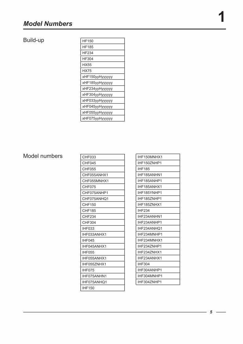
Model Numbers 1HF150HF185HF234HF304HX55HX75xHF150yyHyyyyyyxHF185yyHyyyyyyxHF234yyHyyyyyyxHF304yyHyyyyyyxHF033yyHyyyyyyxHF045yyHyyyyyyxHF055yyHyyyyyyxHF075yyHyyyyyy
Build-up
Model numbers CHF033CHF045CHF055CHF055ANHX1CHF055MNHX1CHF075CHF075ANHP1CHF075ANHQ1CHF150CHF185CHF234CHF304IHF033IHF033ANHX1IHF045IHF045ANHX1IHF055IHF055ANHX1IHF055ZNHX1IHF075IHF075ANHN1IHF075ANHQ1IHF150
IHF150MNHX1IHF150ZNHP1IHF185IHF185ANHN1IHF185ANHP1IHF185ANHX1IHF185YNHP1IHF185ZNHP1IHF185ZNHX1IHF234IHF234ANHN1IHF234ANHP1IHF234ANHQ1IHF234MNHP1IHF234MNHX1IHF234ZNHP1IHF234ZNHX1IHF234ANHX1IHF304IHF304ANHP1IHF304MNHP1IHF304ZNHP1
6
2Safety and Environmental InformationsSafety
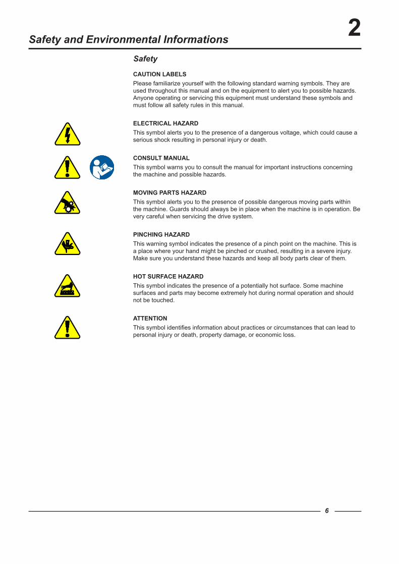
CAUTION LABELSPlease familiarize yourself with the following standard warning symbols. They are used throughout this manual and on the equipment to alert you to possible hazards.Anyone operating or servicing this equipment must understand these symbols and must follow all safety rules in this manual.
ELECTRICAL HAZARDThis symbol alerts you to the presence of a dangerous voltage, which could cause a serious shock resulting in personal injury or death.
CONSULT MANUALThis symbol warns you to consult the manual for important instructions concerning the machine and possible hazards.
MOVING PARTS HAZARD This symbol alerts you to the presence of possible dangerous moving parts within the machine. Guards should always be in place when the machine is in operation. Be very careful when servicing the drive system.
PINCHING HAZARDThis warning symbol indicates the presence of a pinch point on the machine. This is a place where your hand might be pinched or crushed, resulting in a severe injury.Make sure you understand these hazards and keep all body parts clear of them.
HOT SURFACE HAZARDThis symbol indicates the presence of a potentially hot surface. Some machine surfaces and parts may become extremely hot during normal operation and should not be touched.
ATTENTIONThis symbol identifies information about practices or circumstances that can lead to personal injury or death, property damage, or economic loss.
7
2Environmental
Disposal of UnitThis appliance is marked according to the European directive 2002/96/EC on Waste Electrical and Electronic Equipment (WEEE).This symbol on the product or on its packaging indicates that this product shall not be treated as household waste. Instead it shall be handed over to the applicable collection point for the recycling of electrical and electronic equipment. Ensuring this product is disposed of correctly, you will help prevent potential negative consequences for the environment and human health, which could otherwise be caused by inappropriate waste handling of this product. The recycling of materials will help to conserve natural resources. For more detailed information about recycling of this product, please contact your local distributor resources.
8
Explanation of Safety Messages
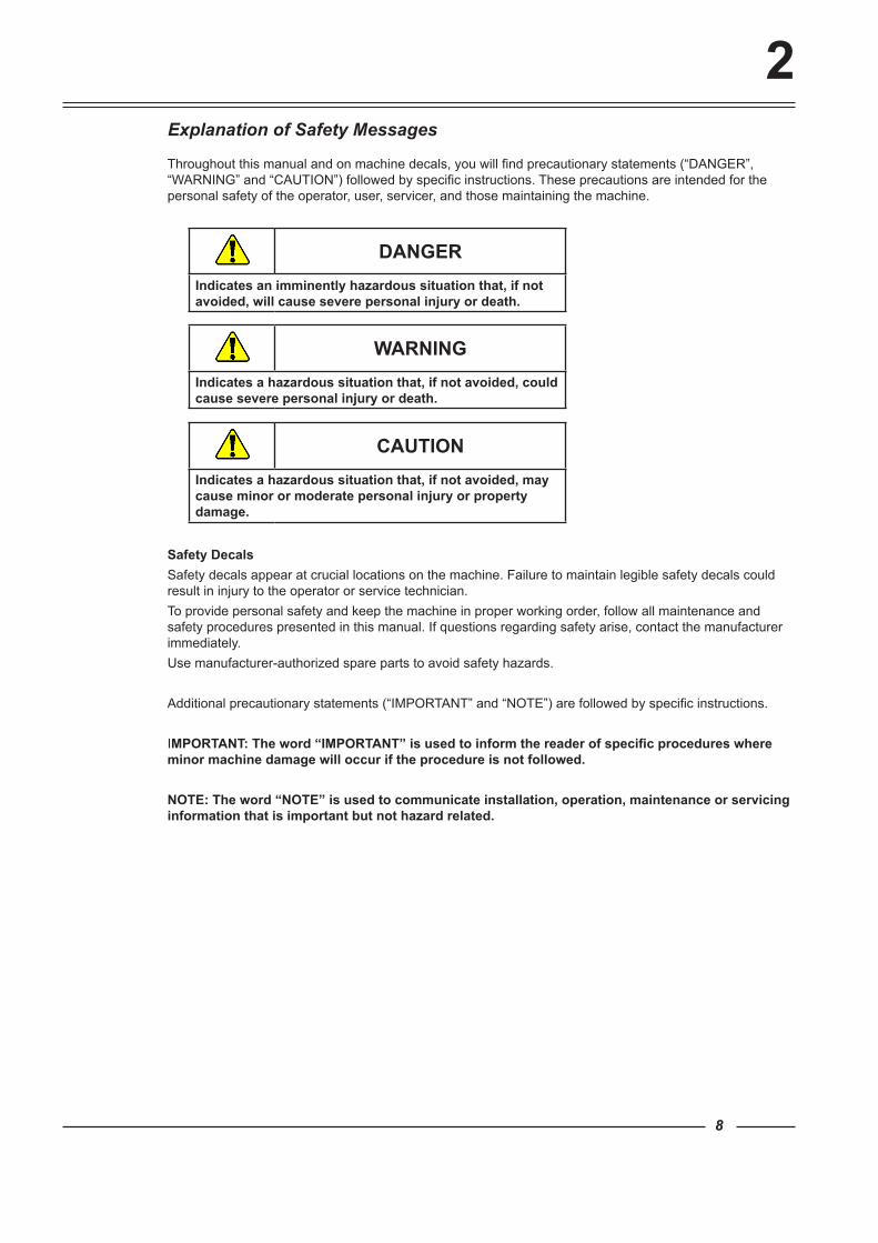
Throughout this manual and on machine decals, you will find precautionary statements (“DANGER”, “WARNING” and “CAUTION”) followed by specific instructions. These precautions are intended for the personal safety of the operator, user, servicer, and those maintaining the machine.
DANGERIndicates an imminently hazardous situation that, if not avoided, will cause severe personal injury or death.
WARNINGIndicates a hazardous situation that, if not avoided, could cause severe personal injury or death.
CAUTIONIndicates a hazardous situation that, if not avoided, may cause minor or moderate personal injury or property damage.
Safety DecalsSafety decals appear at crucial locations on the machine. Failure to maintain legible safety decals could result in injury to the operator or service technician.To provide personal safety and keep the machine in proper working order, follow all maintenance and safety procedures presented in this manual. If questions regarding safety arise, contact the manufacturer immediately.Use manufacturer-authorized spare parts to avoid safety hazards. Additional precautionary statements (“IMPORTANT” and “NOTE”) are followed by specific instructions.
IMPORTANT: The word “IMPORTANT” is used to inform the reader of specific procedures where minor machine damage will occur if the procedure is not followed.
NOTE: The word “NOTE” is used to communicate installation, operation, maintenance or servicing information that is important but not hazard related.
2
9
Important Safety Instructions
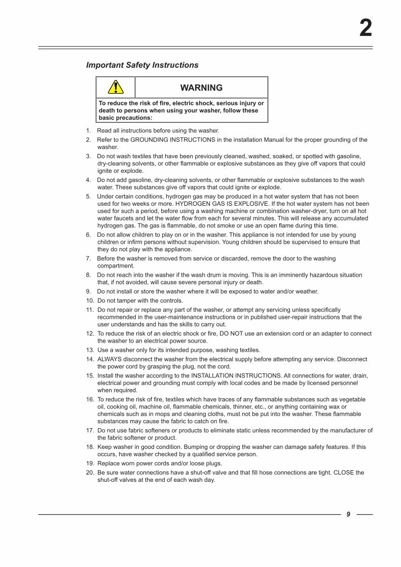
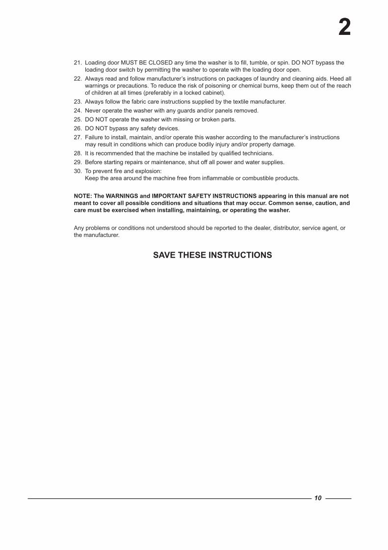
WARNINGTo reduce the risk of fire, electric shock, serious injury or death to persons when using your washer, follow these basic precautions:
1. Read all instructions before using the washer.2. Refer to the GROUNDING INSTRUCTIONS in the installation Manual for the proper grounding of the
washer.3. Do not wash textiles that have been previously cleaned, washed, soaked, or spotted with gasoline,
dry-cleaning solvents, or other flammable or explosive substances as they give off vapors that could ignite or explode.
4. Do not add gasoline, dry-cleaning solvents, or other flammable or explosive substances to the wash water. These substances give off vapors that could ignite or explode.
5. Under certain conditions, hydrogen gas may be produced in a hot water system that has not been used for two weeks or more. HYDROGEN GAS IS EXPLOSIVE. If the hot water system has not been used for such a period, before using a washing machine or combination washer-dryer, turn on all hot water faucets and let the water flow from each for several minutes. This will release any accumulated hydrogen gas. The gas is flammable, do not smoke or use an open flame during this time.
6. Do not allow children to play on or in the washer. This appliance is not intended for use by young children or infirm persons without supervision. Young children should be supervised to ensure that they do not play with the appliance.
7. Before the washer is removed from service or discarded, remove the door to the washing compartment.
8. Do not reach into the washer if the wash drum is moving. This is an imminently hazardous situation that, if not avoided, will cause severe personal injury or death.
9. Do not install or store the washer where it will be exposed to water and/or weather.10. Do not tamper with the controls.11. Do not repair or replace any part of the washer, or attempt any servicing unless specifically
recommended in the user-maintenance instructions or in published user-repair instructions that the user understands and has the skills to carry out.
12. To reduce the risk of an electric shock or fire, DO NOT use an extension cord or an adapter to connect the washer to an electrical power source.
13. Use a washer only for its intended purpose, washing textiles.14. ALWAYS disconnect the washer from the electrical supply before attempting any service. Disconnect
the power cord by grasping the plug, not the cord.15. Install the washer according to the INSTALLATION INSTRUCTIONS. All connections for water, drain,
electrical power and grounding must comply with local codes and be made by licensed personnel when required.
16. To reduce the risk of fire, textiles which have traces of any flammable substances such as vegetable oil, cooking oil, machine oil, flammable chemicals, thinner, etc., or anything containing wax or chemicals such as in mops and cleaning cloths, must not be put into the washer. These flammable substances may cause the fabric to catch on fire.
17. Do not use fabric softeners or products to eliminate static unless recommended by the manufacturer of the fabric softener or product.
18. Keep washer in good condition. Bumping or dropping the washer can damage safety features. If this occurs, have washer checked by a qualified service person.
19. Replace worn power cords and/or loose plugs.20. Be sure water connections have a shut-off valve and that fill hose connections are tight. CLOSE the
shut-off valves at the end of each wash day.
2
10
2221. Loading door MUST BE CLOSED any time the washer is to fill, tumble, or spin. DO NOT bypass the
loading door switch by permitting the washer to operate with the loading door open. 22. Always read and follow manufacturer’s instructions on packages of laundry and cleaning aids. Heed all
warnings or precautions. To reduce the risk of poisoning or chemical burns, keep them out of the reach of children at all times (preferably in a locked cabinet).
23. Always follow the fabric care instructions supplied by the textile manufacturer.24. Never operate the washer with any guards and/or panels removed.25. DO NOT operate the washer with missing or broken parts.26. DO NOT bypass any safety devices.27. Failure to install, maintain, and/or operate this washer according to the manufacturer’s instructions
may result in conditions which can produce bodily injury and/or property damage.28. It is recommended that the machine be installed by qualified technicians.29. Before starting repairs or maintenance, shut off all power and water supplies.30. To prevent fire and explosion:
Keep the area around the machine free from inflammable or combustible products.
NOTE: The WARNINGS and IMPORTANT SAFETY INSTRUCTIONS appearing in this manual are not meant to cover all possible conditions and situations that may occur. Common sense, caution, and care must be exercised when installing, maintaining, or operating the washer.
Any problems or conditions not understood should be reported to the dealer, distributor, service agent, or the manufacturer.
SAVE THESE INSTRUCTIONS
11
Operator Safety
WARNINGNEVER insert hands or objects into basket until it has completely stopped. Doing so could result in serious injury.
To ensure the safety of machine operators, the following maintenance checks must be performed daily:
1. Prior to operating the machine, verify that all warning signs are present and legible. Missing or illegible signs must be replaced immediately. Make certain that spares are available.
2. Check door interlock before starting operation of the machine:a. Attempt to start the machine with the door open. The machine should not start with the door open.b. Close the door without locking it and attempt to start the machine. The machine should not start with
the door unlocked.c. Close and lock the door and start a cycle. Attempt to open the door while the cycle is in progress.
The door should not open.
If the door lock and interlock are not functioning properly, call a service technician.
3. Do not attempt to operate the machine if any of the following conditions are present:a. The door does not remain securely locked during the entire cycle.b. Excessively high water level is evident.c. Machine is not connected to a properly grounded circuit.
Do not bypass any safety devices in the machine.
WARNINGNever operate the machine with a bypassed or disconnected balance system. Operating the machine with severe out-of-balance loads could result in personal injury and serious equipment damage.
SAVE THESE INSTRUCTIONS
2
3
12
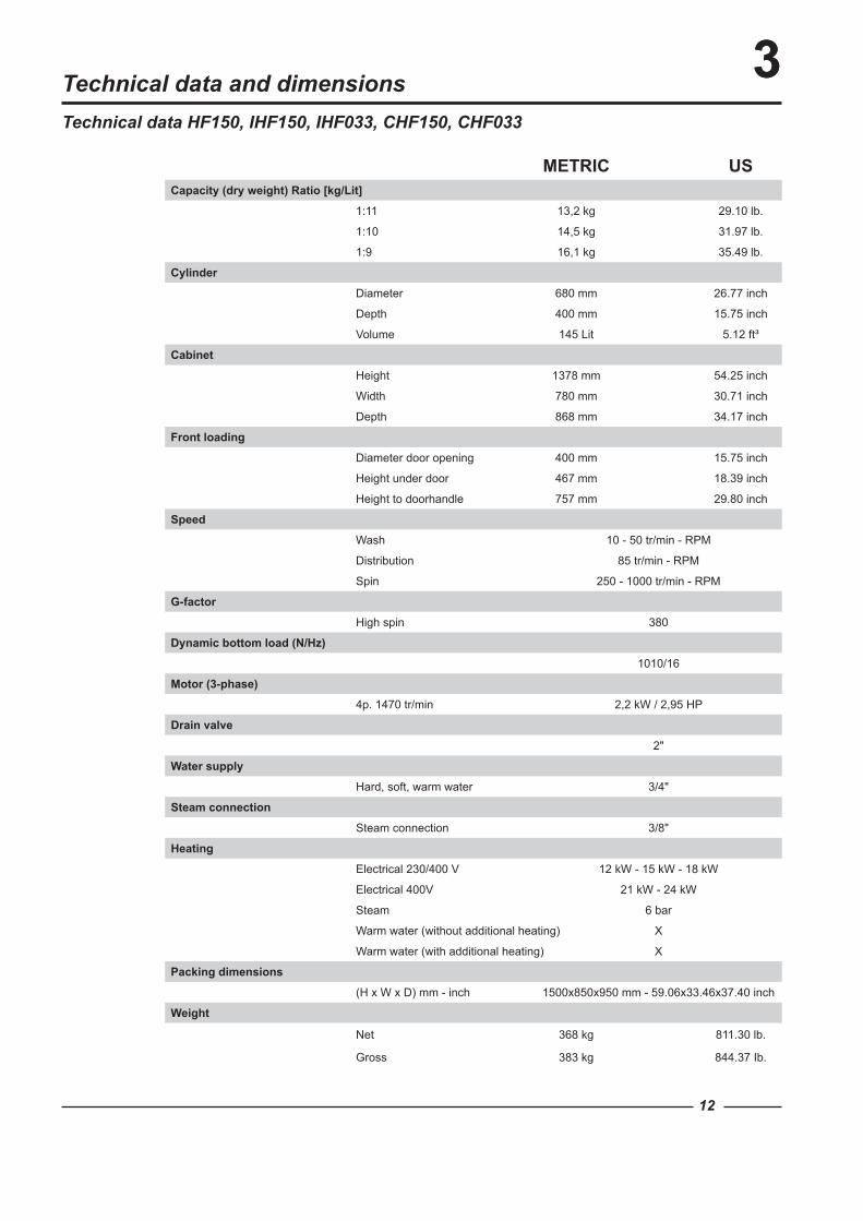
3Technical data HF150, IHF150, IHF033, CHF150, CHF033
Technical data and dimensions
METRIC USCapacity (dry weight) Ratio [kg/Lit]
1:11 13,2 kg 29.10 lb.
1:10 14,5 kg 31.97 lb.
1:9 16,1 kg 35.49 lb.
Cylinder
Diameter 680 mm 26.77 inch
Depth 400 mm 15.75 inch
Volume 145 Lit 5.12 ft³
Cabinet
Height 1378 mm 54.25 inch
Width 780 mm 30.71 inch
Depth 868 mm 34.17 inch
Front loading
Diameter door opening 400 mm 15.75 inch
Height under door 467 mm 18.39 inch
Height to doorhandle 757 mm 29.80 inch
Speed
Wash 10 - 50 tr/min - RPM
Distribution 85 tr/min - RPM
Spin 250 - 1000 tr/min - RPM
G-factor
High spin 380
Dynamic bottom load (N/Hz)
1010/16
Motor (3-phase)
4p. 1470 tr/min 2,2 kW / 2,95 HP
Drain valve
2"
Water supply
Hard, soft, warm water 3/4"
Steam connection
Steam connection 3/8"
Heating
Electrical 230/400 V 12 kW - 15 kW - 18 kW
Electrical 400V 21 kW - 24 kW
Steam 6 bar
Warm water (without additional heating) X
Warm water (with additional heating) X
Packing dimensions
(H x W x D) mm - inch 1500x850x950 mm - 59.06x33.46x37.40 inch
Weight
Net 368 kg 811.30 lb.
Gross 383 kg 844.37 Ib.
170 [6.69]
K
185
[7.2
9]
35 [1.38]
L
E
D
CB
A
I G
F
109 [4.3]
1015
[39.
96]
1066
[41.
95]
1108
[43.
6]
1141
[44.
9]
105 [4.13]
704
[27.
7]
332 [13.05]
267 [10.49]
202 [7.93]
1378
[54.
25]
1350
[53.
15]
780 [30.71]
680 [26.77]
467
[18.
39]
868 [34.17]
858 [33.78]
772 [30.39]
770 [30.31]
858 [33.78]
13
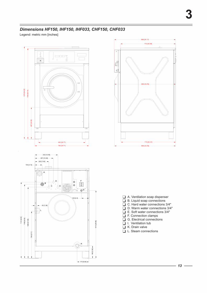
3Dimensions HF150, IHF150, IHF033, CHF150, CHF033
A. Ventilation soap dispenser B. Liquid soap connections C. Hard water connections 3/4" D. Warm water connections 3/4" E. Soft water connections 3/4" F. Connection clamps G. Electrical connections I. Ventilation tub K. Drain valve L. Steam connections
Legend: metric mm [inches]
14
3
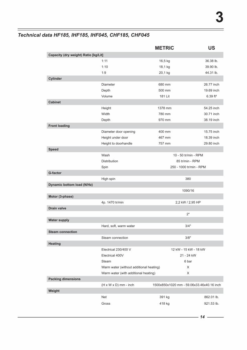
METRIC USCapacity (dry weight) Ratio [kg/Lit]
1:11 16,5 kg 36.38 lb.
1:10 18,1 kg 39.90 lb.
1:9 20,1 kg 44.31 lb.
Cylinder
Diameter 680 mm 26.77 inch
Depth 500 mm 19.69 inch
Volume 181 Lit 6.39 ft³
Cabinet
Height 1378 mm 54.25 inch
Width 780 mm 30.71 inch
Depth 970 mm 38.19 inch
Front loading
Diameter door opening 400 mm 15.75 inch
Height under door 467 mm 18.39 inch
Height to doorhandle 757 mm 29.80 inch
Speed
Wash 10 - 50 tr/min - RPM
Distribution 85 tr/min - RPM
Spin 250 - 1000 tr/min - RPM
G-factor
High spin 380
Dynamic bottom load (N/Hz)
1090/16
Motor (3-phase)
4p. 1470 tr/min 2,2 kW / 2,95 HP
Drain valve
2"
Water supply
Hard, soft, warm water 3/4"
Steam connection
Steam connection 3/8"
Heating
Electrical 230/400 V 12 kW - 15 kW - 18 kW
Electrical 400V 21 - 24 kW
Steam 6 bar
Warm water (without additional heating) X
Warm water (with additional heating) X
Packing dimensions
(H x W x D) mm - inch 1500x850x1020 mm - 59.06x33.46x40.16 inch
Weight
Net 391 kg 862.01 lb.
Gross 418 kg 921.53 Ib.
Technical data HF185, IHF185, IHF045, CHF185, CHF045

863 [33.98]
956 [37.64]
970 [38.19]
874 [34.41]
170 [6.69]
K
185
[7.2
9]
35 [1.38]
L
E
D
CB
A
I G
F
109 [4.3]
1015
[39.
96]
1066
[41.
95]
1108
[43.
6]
1141
[44.
9]
105 [4.13]
704
[27.
7]
332 [13.05]
267 [10.49]
202 [7.93]
1378
[54.
25]
1350
[53.
15]
780 [30.71]
680 [26.77]
467
[18.
39]
15
3Dimensions HF185, IHF185, IHF045, CHF185, CHF045Legend: metric mm [inches]
A. Ventilation soap dispenser B. Liquid soap connections C. Hard water connections 3/4" D. Warm water connections 3/4" E. Soft water connections 3/4" F. Connection clamps G. Electrical connections I. Ventilation tub K. Drain valve L. Steam connections
16
3
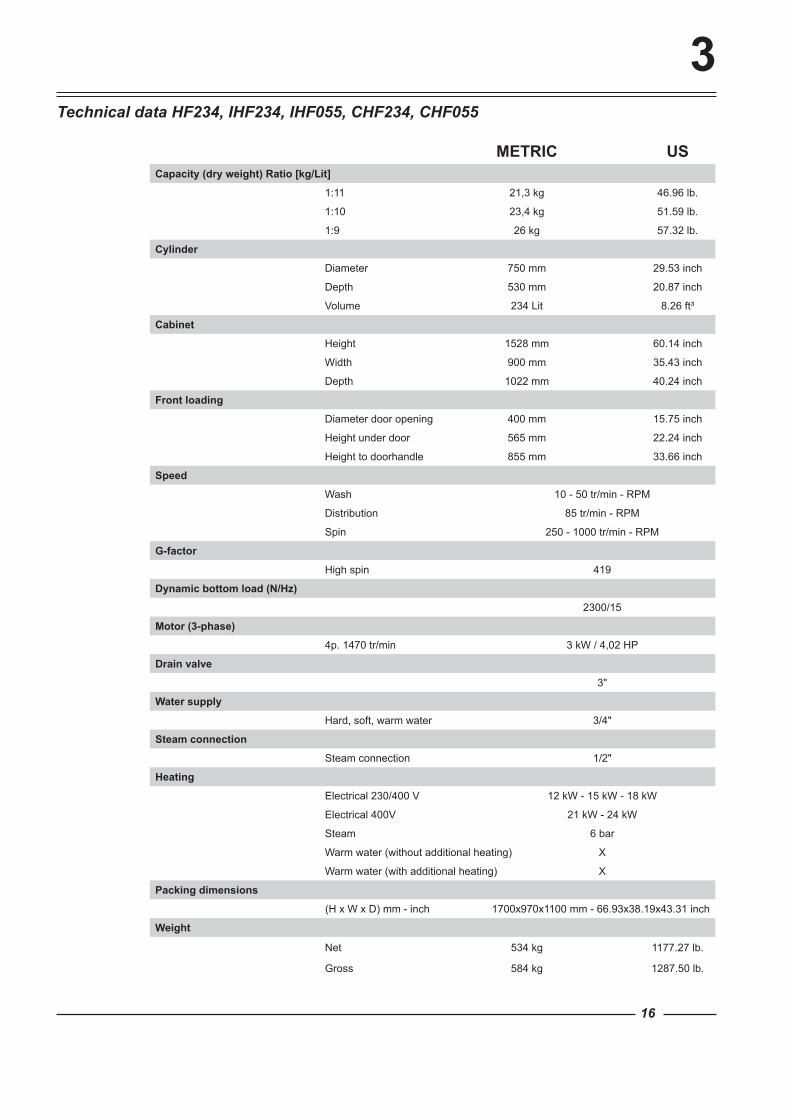
METRIC USCapacity (dry weight) Ratio [kg/Lit]
1:11 21,3 kg 46.96 lb.
1:10 23,4 kg 51.59 lb.
1:9 26 kg 57.32 lb.
Cylinder
Diameter 750 mm 29.53 inch
Depth 530 mm 20.87 inch
Volume 234 Lit 8.26 ft³
Cabinet
Height 1528 mm 60.14 inch
Width 900 mm 35.43 inch
Depth 1022 mm 40.24 inch
Front loading
Diameter door opening 400 mm 15.75 inch
Height under door 565 mm 22.24 inch
Height to doorhandle 855 mm 33.66 inch
Speed
Wash 10 - 50 tr/min - RPM
Distribution 85 tr/min - RPM
Spin 250 - 1000 tr/min - RPM
G-factor
High spin 419
Dynamic bottom load (N/Hz)
2300/15
Motor (3-phase)
4p. 1470 tr/min 3 kW / 4,02 HP
Drain valve
3"
Water supply
Hard, soft, warm water 3/4"
Steam connection
Steam connection 1/2"
Heating
Electrical 230/400 V 12 kW - 15 kW - 18 kW
Electrical 400V 21 kW - 24 kW
Steam 6 bar
Warm water (without additional heating) X
Warm water (with additional heating) X
Packing dimensions
(H x W x D) mm - inch 1700x970x1100 mm - 66.93x38.19x43.31 inch
Weight
Net 534 kg 1177.27 lb.
Gross 584 kg 1287.50 lb.
Technical data HF234, IHF234, IHF055, CHF234, CHF055
720
[28.
35]
1266
[49.
82]
1386
[54.
57]
156 [6.12]
251 [9.88]
346 [13.62]
C D E
35 [1.38]
L
B
A
1126
.9 [4
4.36
]
105 [4.13]
165
[6.5
]
K
116 [4.57]
GI
1500
[59.
05]
738 [29.05]
900 [35.43]
1528
[60.
14]
565
[22.
24]
H
946.5 [37.26]
1022 [40.24]
1002 [39.45]
940 [37.01]
3
F
H
17
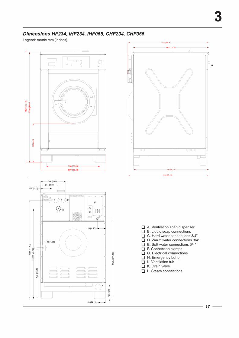
Dimensions HF234, IHF234, IHF055, CHF234, CHF055Legend: metric mm [inches]
A. Ventilation soap dispenser B. Liquid soap connections C. Hard water connections 3/4" D. Warm water connections 3/4" E. Soft water connections 3/4" F. Connection clamps G. Electrical connections H. Emergency button I. Ventilation tub K. Drain valve L. Steam connections

18
3
METRIC USCapacity (dry weight) Ratio [kg/Lit]
1:11 27,6 kg 60.85 lb.
1:10 30,4 kg 67.02 lb.
1:9 33,8 kg 74.52 lb.
Cylinder
Diameter 850 mm 33.46 inch
Depth 537 mm 21.14 inch
Volume 304 Lit 10.74 ft³
Cabinet
Height 1558 mm 61.32 inch
Width 1060 mm 41.73 inch
Depth 1160 mm 45.67 inch
Front loading
Diameter door opening 400 mm 15.75 inch
Height under door 570 mm 22.44 inch
Height to doorhandle 860 mm 33.86 inch
Speed
Wash 10 - 50 tr/min - RPM
Distribution 85 tr/min - RPM
Spin 250 - 1000 tr/min - RPM
G-factor
High spin 475
Dynamic bottom load (N/Hz)
2340/15
Motor (3-phase)
4p. 1470 tr/min 4 kW / 5,36 HP
Drain valve
3"
Water supply
Hard, soft, warm water 3/4"
Steam connection
Steam connection 1/2"
Heating
Electrical 230/400 V 18 kW
Electrical 400V 21 kW - 24 kW
Steam 6 bar
Warm water (without additional heating) X
Warm water (with additional heating) X
Packing dimensions
(H x W x D) mm - inch 1740x1120x1260 mm - 68.50x44.09x49.61inch
Weight
Net 731 kg 1611.58 lb.
Gross 781 kg 1721.81 lb.
Technical data HF304, IHF304, IHF075, CHF304, CHF075
247 [9.72]
1403
[55.
24]
105 [4.13]
170
[6.6
9]
35 [1.38]
580
[22.
83]
1312
[51.
65]
L
367.5 [14.47]
187 [7.36]
488 [19.21]
1167
[45.
93]
I G
EDC
B
A
K
1530
[60.
24]
865 [34.06]
1060 [41.73]
1558
[61.
32]
570
[22.
44]
1078 [42.44]
1160 [45.67]
1074 [42.28]
1158 [45.59]
H H
F
19
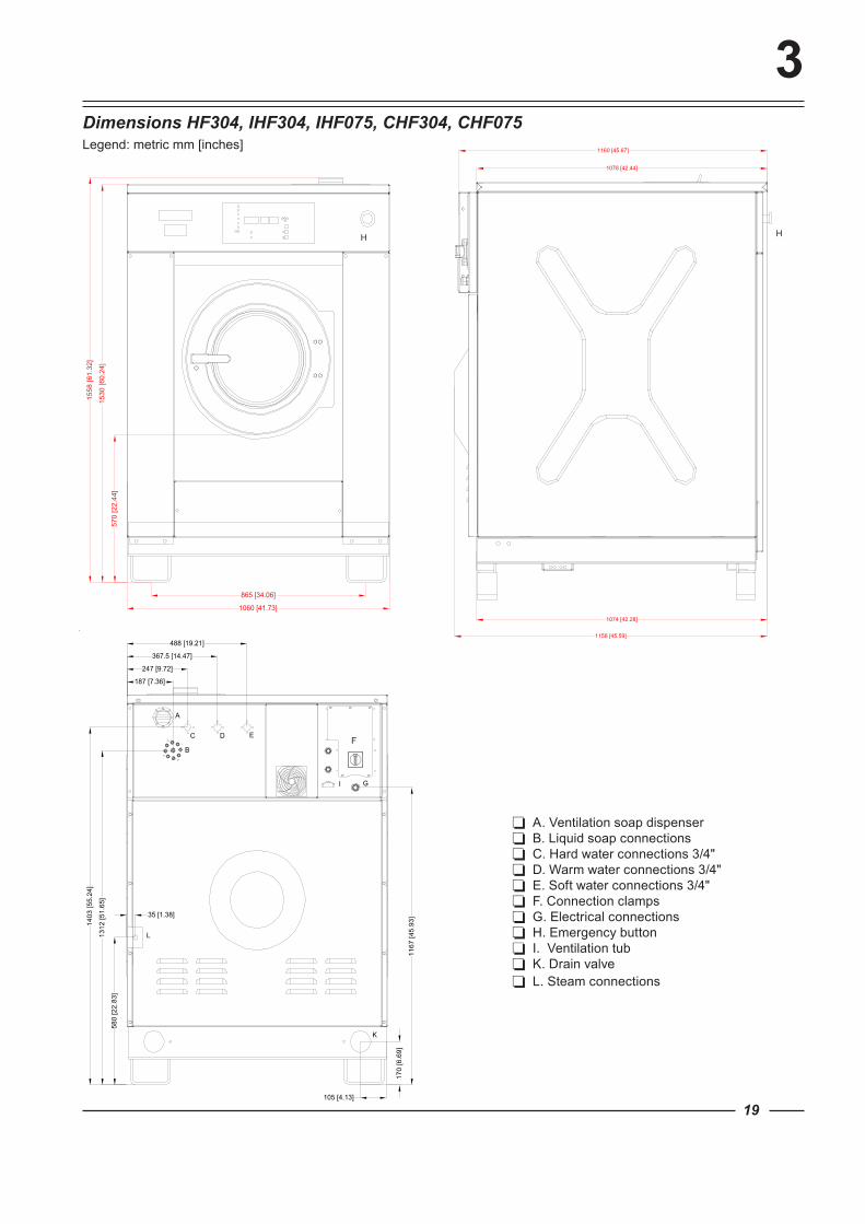
3Dimensions HF304, IHF304, IHF075, CHF304, CHF075Legend: metric mm [inches]
A. Ventilation soap dispenser B. Liquid soap connections C. Hard water connections 3/4" D. Warm water connections 3/4" E. Soft water connections 3/4" F. Connection clamps G. Electrical connections H. Emergency button I. Ventilation tub K. Drain valve L. Steam connections
Label 1
1/21/2
1/3
Label 2
20
4Installation and Connection Instructions
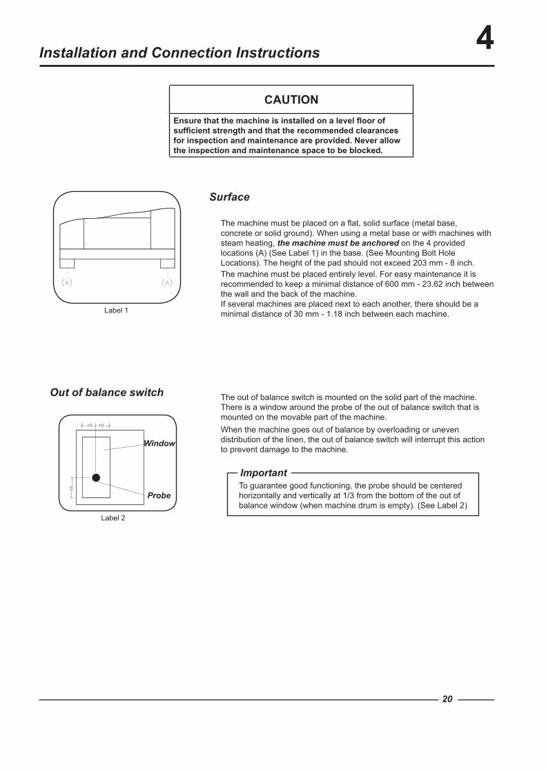
Surface
CAUTIONEnsure that the machine is installed on a level floor of sufficient strength and that the recommended clearances for inspection and maintenance are provided. Never allow the inspection and maintenance space to be blocked.
The machine must be placed on a flat, solid surface (metal base, concrete or solid ground). When using a metal base or with machines with steam heating, the machine must be anchored on the 4 provided locations (A) (See Label 1) in the base. (See Mounting Bolt Hole Locations). The height of the pad should not exceed 203 mm - 8 inch.The machine must be placed entirely level. For easy maintenance it is recommended to keep a minimal distance of 600 mm - 23.62 inch between the wall and the back of the machine.If several machines are placed next to each another, there should be a minimal distance of 30 mm - 1.18 inch between each machine.
The out of balance switch is mounted on the solid part of the machine. There is a window around the probe of the out of balance switch that is mounted on the movable part of the machine.When the machine goes out of balance by overloading or uneven distribution of the linen, the out of balance switch will interrupt this action to prevent damage to the machine.
Important
Out of balance switch
To guarantee good functioning, the probe should be centered horizontally and vertically at 1/3 from the bottom of the out of balance window (when machine drum is empty). (See Label 2)
Window
Probe
HF234-304
Label 3
Label 4
HF150-185
4
21
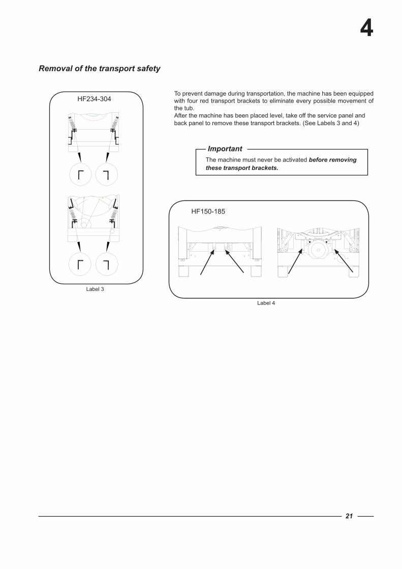
To prevent damage during transportation, the machine has been equipped with four red transport brackets to eliminate every possible movement of the tub.After the machine has been placed level, take off the service panel and back panel to remove these transport brackets. (See Labels 3 and 4)
Important
Removal of the transport safety
The machine must never be activated before removing these transport brackets.
680 [26.77]
780 [30.71]
50 [1.97] 50 [1.97]
34 [1
.34]
34 [1
.34]
Ø22 [Ø0.87]
665
[26.
18]
733
[28.
86]
22
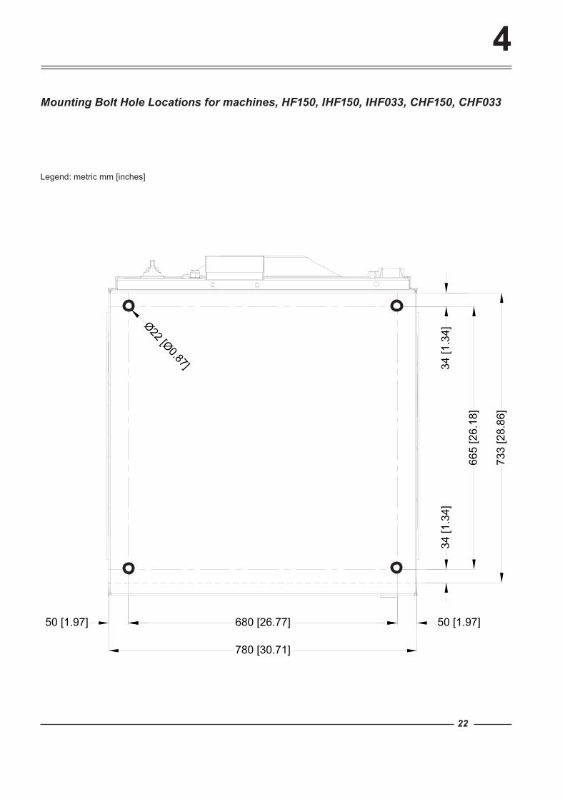
4Mounting Bolt Hole Locations for machines, HF150, IHF150, IHF033, CHF150, CHF033
Legend: metric mm [inches]
680 [26.77]
780 [30.71]
50 [1.97] 50 [1.97]
34 [1
.34]
34 [1
.34]
Ø22 [Ø0.87]
765
[30.
12]
833
[32.
8]
23
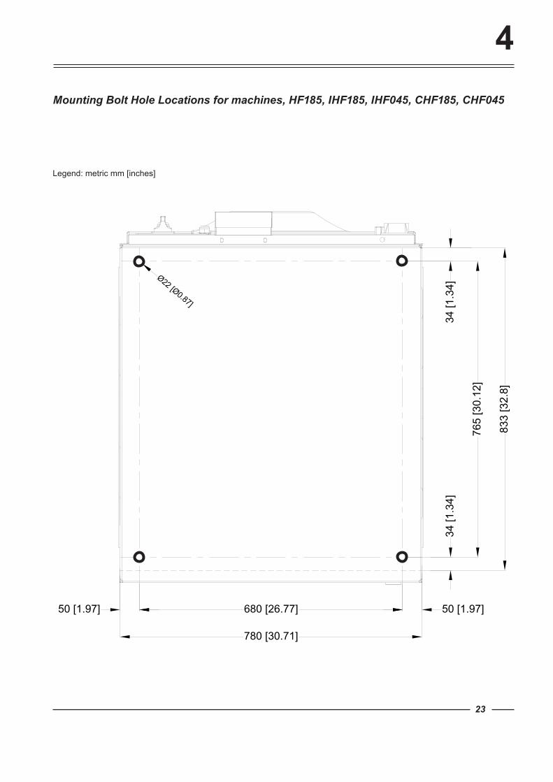
4Mounting Bolt Hole Locations for machines, HF185, IHF185, IHF045, CHF185, CHF045
Legend: metric mm [inches]
Ø22 [Ø0.87]
738 [29.05]
830
[32.
68]
81 [3.19] 81 [3.19]
35 [1
.38]
35 [1
.38]
900 [35.43]
900
[35.
43]
24
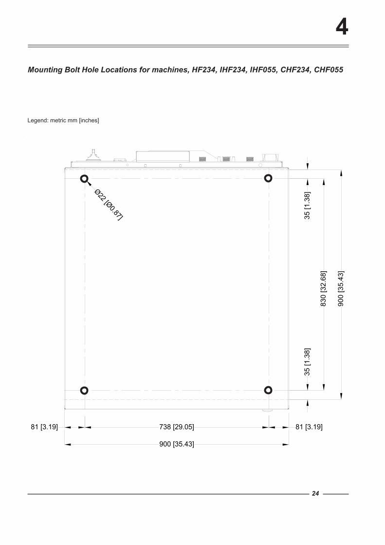
Mounting Bolt Hole Locations for machines, HF234, IHF234, IHF055, CHF234, CHF055
4
Legend: metric mm [inches]
4
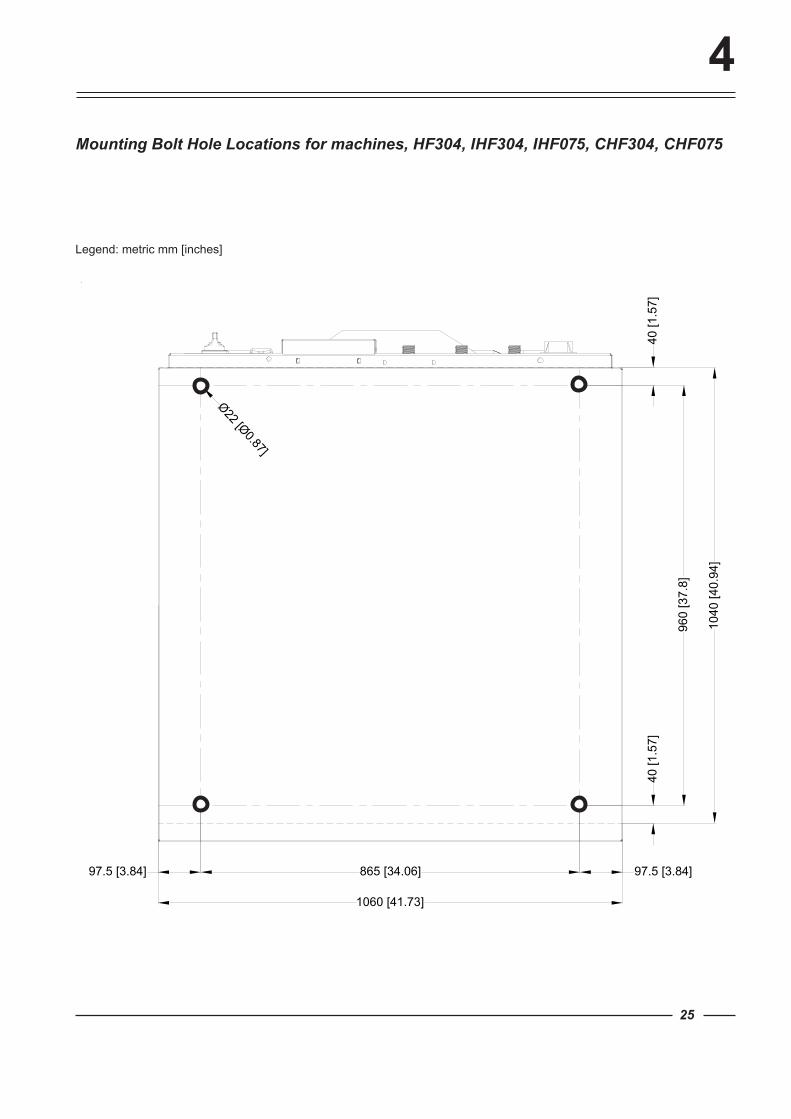
1060 [41.73]
Ø22 [Ø0.87]
865 [34.06]97.5 [3.84] 97.5 [3.84]
960
[37.
8]
1040
[40.
94]
40 [1
.57]
40 [1
.57]
25
Mounting Bolt Hole Locations for machines, HF304, IHF304, IHF075, CHF304, CHF075
Legend: metric mm [inches]
26
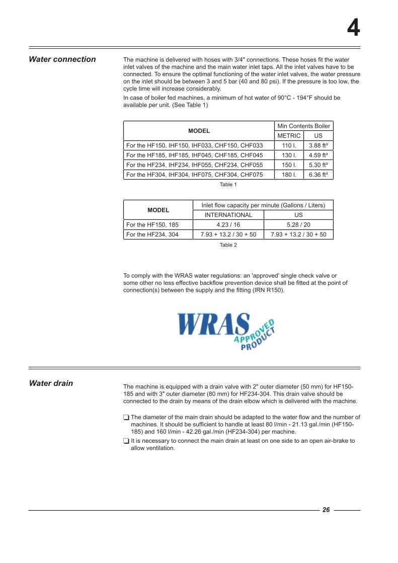
4The machine is delivered with hoses with 3/4" connections. These hoses fit the water inlet valves of the machine and the main water inlet taps. All the inlet valves have to be connected. To ensure the optimal functioning of the water inlet valves, the water pressure on the inlet should be between 3 and 5 bar (40 and 80 psi). If the pressure is too low, the cycle time will increase considerably.In case of boiler fed machines, a minimum of hot water of 90°C - 194°F should be available per unit. (See Table 1)
MODELMin Contents BoilerMETRIC US
For the HF150, IHF150, IHF033, CHF150, CHF033 110 l. 3.88 ft³For the HF185, IHF185, IHF045, CHF185, CHF045 130 l. 4.59 ft³For the HF234, IHF234, IHF055, CHF234, CHF055 150 l. 5.30 ft³For the HF304, IHF304, IHF075, CHF304, CHF075 180 l. 6.36 ft³
MODELInlet flow capacity per minute (Gallons / Liters)INTERNATIONAL US
For the HF150, 185 4.23 / 16 5.28 / 20For the HF234, 304 7.93 + 13.2 / 30 + 50 7.93 + 13.2 / 30 + 50
Water connection
The diameter of the main drain should be adapted to the water flow and the number of machines. It should be sufficient to handle at least 80 l/min - 21.13 gal./min (HF150-185) and 160 l/min - 42.26 gal./min (HF234-304) per machine.
It is necessary to connect the main drain at least on one side to an open air-brake to allow ventilation.
The machine is equipped with a drain valve with 2" outer diameter (50 mm) for HF150-185 and with 3" outer diameter (80 mm) for HF234-304. This drain valve should be connected to the drain by means of the drain elbow which is delivered with the machine.
Water drain
Table 1
Table 2
To comply with the WRAS water regulations: an 'approved' single check valve or some other no less effective backflow prevention device shall be fitted at the point of connection(s) between the supply and the fitting (IRN R150).
4
27
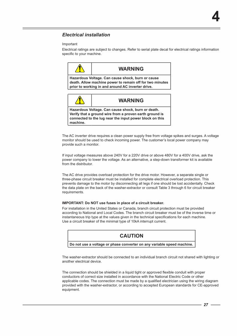
Electrical installation
ImportantElectrical ratings are subject to changes. Refer to serial plate decal for electrical ratings information specific to your machine.
WARNINGHazardous Voltage. Can cause shock, burn or cause death. Allow machine power to remain off for two minutes prior to working in and around AC inverter drive.
WARNINGHazardous Voltage. Can cause shock, burn or death. Verify that a ground wire from a proven earth ground is connected to the lug near the input power block on this machine.
The AC inverter drive requires a clean power supply free from voltage spikes and surges. A voltage monitor should be used to check incoming power. The customer’s local power company may provide such a monitor.
If input voltage measures above 240V for a 220V drive or above 480V for a 400V drive, ask the power company to lower the voltage. As an alternative, a step-down transformer kit is available from the distributor.
The AC drive provides overload protection for the drive motor. However, a separate single or three-phase circuit breaker must be installed for complete electrical overload protection. This prevents damage to the motor by disconnecting all legs if one should be lost accidentally. Check the data plate on the back of the washer-extractor or consult Table 3 through 6 for circuit breaker requirements.
IMPORTANT: Do NOT use fuses in place of a circuit breaker.For installation in the United States or Canada, branch circuit protection must be provided according to National and Local Codes. The branch circuit breaker must be of the inverse time or instantaneous trip type at the values given in the technical specifications for each machine. Use a circuit breaker of the minimal type of 10kA interrupt current.
CAUTIONDo not use a voltage or phase converter on any variable speed machine.
The washer-extractor should be connected to an individual branch circuit not shared with lighting or another electrical device.
The connection should be shielded in a liquid tight or approved flexible conduit with proper conductors of correct size installed in accordance with the National Electric Code or other applicable codes. The connection must be made by a qualified electrician using the wiring diagram provided with the washer-extractor, or according to accepted European standards for CE-approved equipment.
4
28
Use wire sizes indicated in Table 3 through 6 for runs up to 50 feet.
Use next larger size for runs of 50 to 100 feet. Use two sizes larger for runs greater than 100 feet.
For personal safety and proper operation, the washer-extractor must be grounded in accordance with state and local standards. If such standards are not available, grounding must conform to the National Electric Code, article 250. The ground connection must be made to a proven earth ground, not to a water pipe, gas pipe, or another metal pipe. Provide the necessary equipotential connections according to the local electrical prescriptions.
GROUNDING INSTRUCTIONSThis appliance must be connected to a grounded metal, permanent wiring system; or an equipment-grounding conductor must be run with the circuit conductors and connected to the equipment-grounding terminal or lead on the appliance.
IMPORTANT: Alliance Laundry Systems Warranty does not cover components that fail as a result of improper input voltage.
4
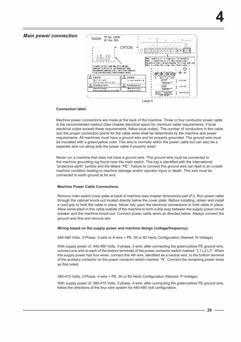
Label 5
29
Connection label:
Machine power connections are made at the back of the machine. Three or four conductor power cable is the recommended method (See chapter electrical specs for minimum cable requirements, if local electrical codes exceed these requirements, follow local codes). The number of conductors in this cable and the proper connection points for the cable wires shall be determined by the machine and power requirements. All machines must have a ground wire and be properly grounded. The ground wire must be insulated with a green/yellow color. This wire is normally within the power cable but can also be a separate wire run along side the power cable if properly sized.
Never run a machine that does not have a ground wire. This ground wire must be connected to the machine grounding lug found near the main switch. This lug is identified with the international “protective earth” symbol and the letters “PE”. Failure to connect this ground wire can lead to an unsafe machine condition leading to machine damage and/or operator injury or death. This wire must be connected to earth ground at far end.
Machine Power Cable Connections:
Remove main switch cover plate at back of machine (see chapter dimensions part (F)). Run power cable through the cabinet knock-out located directly below the cover plate. Before installing, obtain and install a cord-grip to hold the cable in place. Never rely upon the electrical connections to hold cable in place. Allow some slack in this cable outside of the machine to form a drip-loop between the supply power circuit breaker and the machine knock-out. Connect power cable wires as directed below. Always connect the ground wire first and remove last.
Wiring based on the supply power and machine design (voltage/frequency):
440-480 Volts, 3-Phase, 3-wire or 4-wire + PE, 50 or 60 Hertz Configuration (Named: N-Voltage):
With supply power of: 440-480 Volts, 3-phase, 3-wire, after connecting the green/yellow PE ground wire, connect one wire to each of the bottom terminals of the power contactor switch marked: “L1,L2,L3”. When this supply power has four wires, connect this 4th wire, identified as a neutral wire, to the bottom terminal of the auxiliary contactor on the power contactor switch marked: “N”. Connect the remaining power wires as first noted.
380-415 Volts, 3-Phase, 4-wire + PE, 50 or 60 Hertz Configuration (Named: P-Voltage):
With supply power of: 380-415 Volts, 3-phase, 4-wire, after connecting the green/yellow PE ground wire, follow the directions of the four wire system for 440-480 Volt configuration.
Main power connection
4
30
200-240 Volts, 3-Phase, 3-wire + PE, 50 or 60 Hertz Configuration (Named: Q-Voltage or 3-phase X-Voltage):
With supply power of: 200-240 Volts, 3-phase, 3-wire, after connecting the green/yellow PE ground wire, connect one power wire to each of the terminals at the bottom of the power contactor switch marked: “L1,L2,L3”.
200-240 volts, 1-Phase, 2-wire + PE, 50 Hertz (called 1-phase, 50 Hz X-voltage):
With supply power of: 200-240 Volts, 1-phase, 2-wire, 50Hz, after connecting the green/yellow PE ground wire, connect the power wire to the “L1” bottom terminal of the power contactor switch and the other wire, identified as the neutral wire, to the bottom terminal of the auxiliary contactor on the power contactor switch marked: “N”.
200-240 volts, 1-Phase, 2-wire + PE, 60 Hertz (called 1-phase, 60 Hz X-voltage):
With supply power of: 200-240 Volts, 1-phase, 2-wire, 60Hz, after connecting the green/yellow PE ground wire, connect one power wire to the “L1” and power wire to the “L2” of the bottom terminals of the power contactor switch.
After connection, check the spin direction. The cylinder must spin in the clockwise direction. A wrong spin direction can damage the motor and can also cause water to spurt from the soap dispenser.
In case of wrong spin direction: switch the terminal clamps of the motor circuit “R” and “S” of the connecting cable or change the connection at the terminal block switching the L1 and L2 wires.
4
31
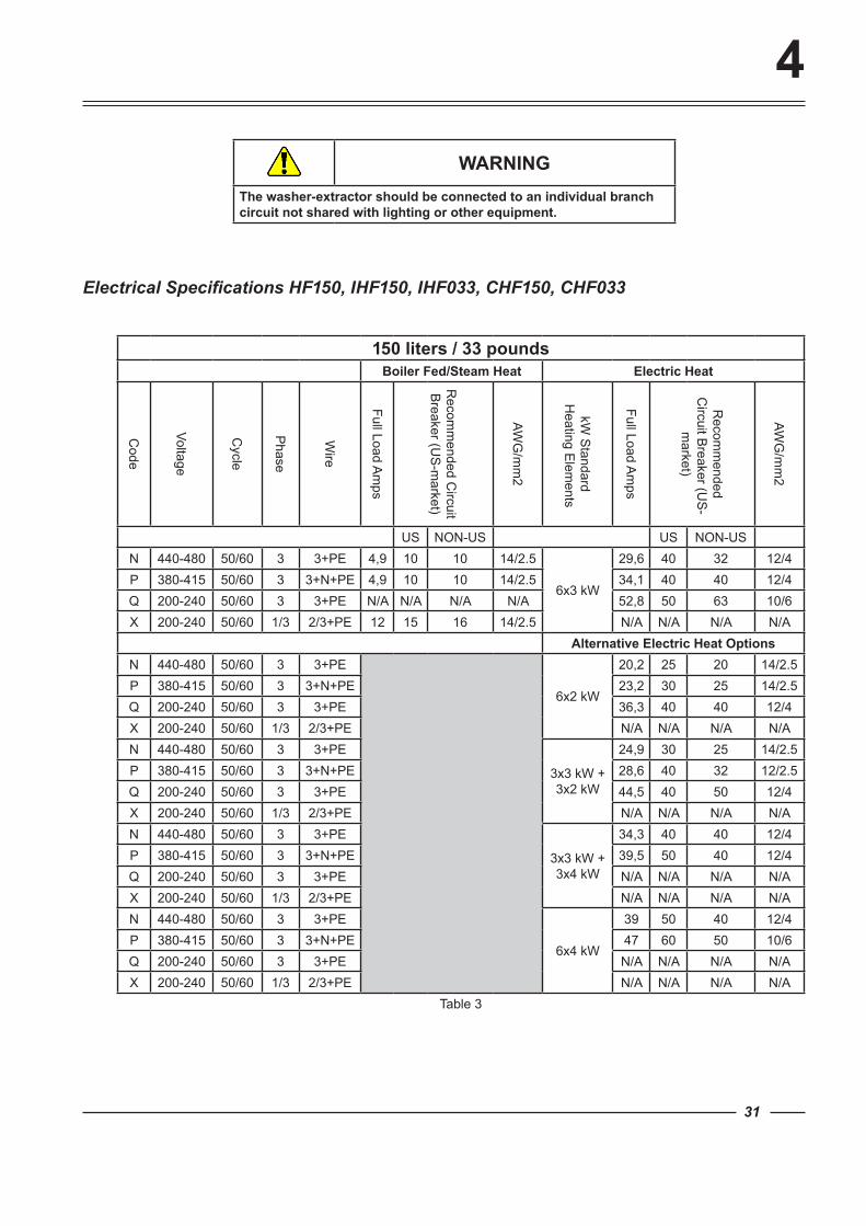
WARNINGThe washer-extractor should be connected to an individual branch circuit not shared with lighting or other equipment.
Electrical Specifications HF150, IHF150, IHF033, CHF150, CHF033
150 liters / 33 poundsBoiler Fed/Steam Heat Electric Heat
Code
Voltage
Cycle
Phase
Wire
Full Load Am
ps
Recom
mended C
ircuit B
reaker (US
-market)
AWG
/mm
2
kW S
tandard H
eating Elem
ents
Full Load Am
ps
Recom
mended
Circuit B
reaker (US
-m
arket)
AWG
/mm
2
US NON-US US NON-USN 440-480 50/60 3 3+PE 4,9 10 10 14/2.5
6x3 kW
29,6 40 32 12/4P 380-415 50/60 3 3+N+PE 4,9 10 10 14/2.5 34,1 40 40 12/4Q 200-240 50/60 3 3+PE N/A N/A N/A N/A 52,8 50 63 10/6X 200-240 50/60 1/3 2/3+PE 12 15 16 14/2.5 N/A N/A N/A N/A
Alternative Electric Heat OptionsN 440-480 50/60 3 3+PE
6x2 kW
20,2 25 20 14/2.5P 380-415 50/60 3 3+N+PE 23,2 30 25 14/2.5Q 200-240 50/60 3 3+PE 36,3 40 40 12/4X 200-240 50/60 1/3 2/3+PE N/A N/A N/A N/AN 440-480 50/60 3 3+PE
3x3 kW + 3x2 kW
24,9 30 25 14/2.5P 380-415 50/60 3 3+N+PE 28,6 40 32 12/2.5Q 200-240 50/60 3 3+PE 44,5 40 50 12/4X 200-240 50/60 1/3 2/3+PE N/A N/A N/A N/AN 440-480 50/60 3 3+PE
3x3 kW + 3x4 kW
34,3 40 40 12/4P 380-415 50/60 3 3+N+PE 39,5 50 40 12/4Q 200-240 50/60 3 3+PE N/A N/A N/A N/AX 200-240 50/60 1/3 2/3+PE N/A N/A N/A N/AN 440-480 50/60 3 3+PE
6x4 kW
39 50 40 12/4P 380-415 50/60 3 3+N+PE 47 60 50 10/6Q 200-240 50/60 3 3+PE N/A N/A N/A N/AX 200-240 50/60 1/3 2/3+PE N/A N/A N/A N/A
Table 3
4
32
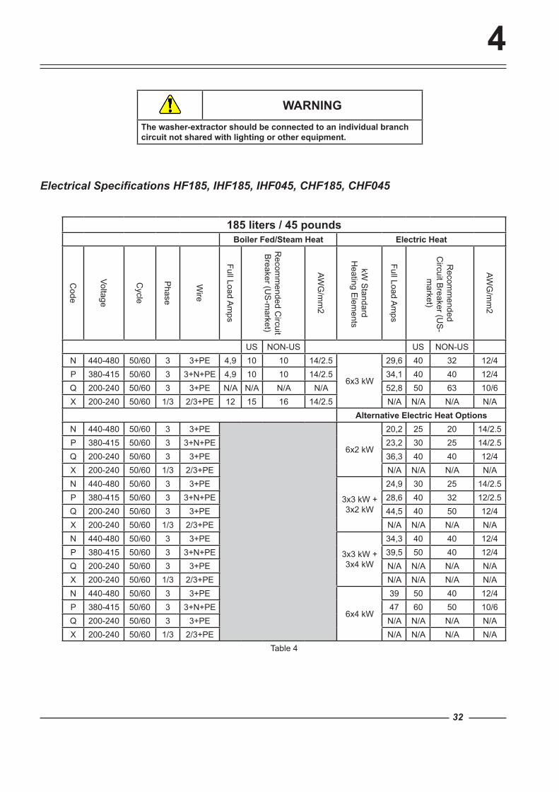
WARNINGThe washer-extractor should be connected to an individual branch circuit not shared with lighting or other equipment.
Electrical Specifications HF185, IHF185, IHF045, CHF185, CHF045
185 liters / 45 poundsBoiler Fed/Steam Heat Electric Heat
Code
Voltage
Cycle
Phase
Wire
Full Load Am
ps
Recom
mended C
ircuit B
reaker (US
-market)
AWG
/mm
2
kW S
tandard H
eating Elem
ents
Full Load Am
ps
Recom
mended
Circuit B
reaker (US
-m
arket)
AWG
/mm
2
US NON-US US NON-USN 440-480 50/60 3 3+PE 4,9 10 10 14/2.5
6x3 kW
29,6 40 32 12/4P 380-415 50/60 3 3+N+PE 4,9 10 10 14/2.5 34,1 40 40 12/4Q 200-240 50/60 3 3+PE N/A N/A N/A N/A 52,8 50 63 10/6X 200-240 50/60 1/3 2/3+PE 12 15 16 14/2.5 N/A N/A N/A N/A
Alternative Electric Heat OptionsN 440-480 50/60 3 3+PE
6x2 kW
20,2 25 20 14/2.5P 380-415 50/60 3 3+N+PE 23,2 30 25 14/2.5Q 200-240 50/60 3 3+PE 36,3 40 40 12/4X 200-240 50/60 1/3 2/3+PE N/A N/A N/A N/AN 440-480 50/60 3 3+PE
3x3 kW + 3x2 kW
24,9 30 25 14/2.5P 380-415 50/60 3 3+N+PE 28,6 40 32 12/2.5Q 200-240 50/60 3 3+PE 44,5 40 50 12/4X 200-240 50/60 1/3 2/3+PE N/A N/A N/A N/AN 440-480 50/60 3 3+PE
3x3 kW + 3x4 kW
34,3 40 40 12/4P 380-415 50/60 3 3+N+PE 39,5 50 40 12/4Q 200-240 50/60 3 3+PE N/A N/A N/A N/AX 200-240 50/60 1/3 2/3+PE N/A N/A N/A N/AN 440-480 50/60 3 3+PE
6x4 kW
39 50 40 12/4P 380-415 50/60 3 3+N+PE 47 60 50 10/6Q 200-240 50/60 3 3+PE N/A N/A N/A N/AX 200-240 50/60 1/3 2/3+PE N/A N/A N/A N/A
Table 4

4
33
WARNINGThe washer-extractor should be connected to an individual branch circuit not shared with lighting or other equipment.
Electrical Specifications HF234, IHF234, IHF055, CHF234, CHF055
234 liters / 55 poundsBoiler Fed/Steam Heat Electric Heat
Code
Voltage
Cycle
Phase
Wire
Full Load Am
ps
Recom
mended C
ircuit B
reaker (US
-market)
AWG
/mm
2
kW S
tandard H
eating Elem
ents
Full Load Am
ps
Recom
mended
Circuit B
reaker (US
-m
arket)
AWG
/mm
2
US NON-US US NON-USN 440-480 50/60 3 3+PE 6,5 15 16 14/2.5
6x3 kW
29,8 40 32 12/4P 380-415 50/60 3 3+N+PE 6,5 15 16 14/2.5 34,2 40 40 12/4Q 200-240 50/60 3 3+PE N/A N/A N/A N/A 53,3 50 63 10/6X 200-240 50/60 1/3 2/3+PE 16 20 20 14/2.5 N/A N/A N/A N/A
Alternative Electric Heat OptionsN 440-480 50/60 3 3+PE
6x2 kW
20,4 25 20 14/2.5P 380-415 50/60 3 3+N+PE 23,4 30 25 14/2.5Q 200-240 50/60 3 3+PE 36,8 40 40 12/4X 200-240 50/60 1/3 2/3+PE N/A N/A N/A N/AN 440-480 50/60 3 3+PE
3x3 kW + 3x2 kW
25,1 30 25 14/2.5P 380-415 50/60 3 3+N+PE 28,8 40 32 12/2.5Q 200-240 50/60 3 3+PE 45 40 50 12/4X 200-240 50/60 1/3 2/3+PE N/A N/A N/A N/AN 440-480 50/60 3 3+PE
3x3 kW + 3x4 kW
34,5 50 50 12/4P 380-415 50/60 3 3+N+PE 39,7 50 40 12/4Q 200-240 50/60 3 3+PE N/A N/A N/A N/AX 200-240 50/60 1/3 2/3+PE N/A N/A N/A N/AN 440-480 50/60 3 3+PE
6x4 kW
39,2 50 40 12/4P 380-415 50/60 3 3+N+PE 47,5 60 63 10/6Q 200-240 50/60 3 3+PE N/A N/A N/A N/AX 200-240 50/60 1/3 2/3+PE N/A N/A N/A N/A
Table 5
4
34
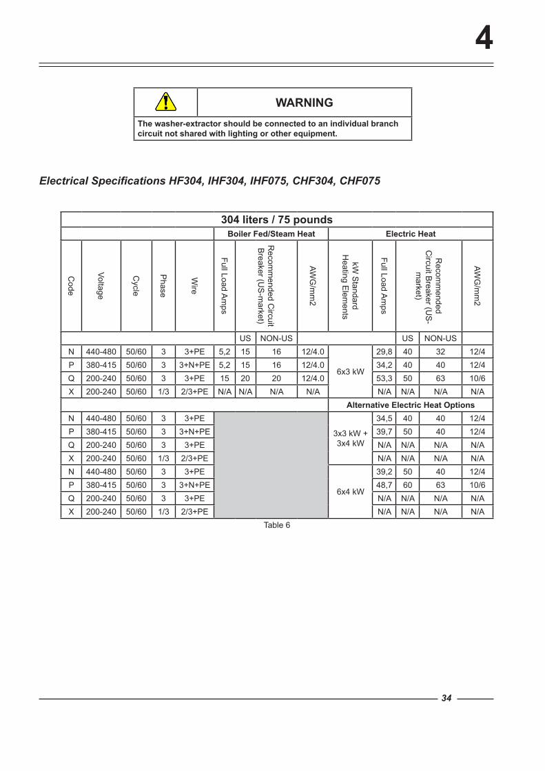
WARNINGThe washer-extractor should be connected to an individual branch circuit not shared with lighting or other equipment.
Electrical Specifications HF304, IHF304, IHF075, CHF304, CHF075
304 liters / 75 poundsBoiler Fed/Steam Heat Electric Heat
Code
Voltage
Cycle
Phase
Wire
Full Load Am
ps
Recom
mended C
ircuit B
reaker (US
-market)
AWG
/mm
2
kW S
tandard H
eating Elem
ents
Full Load Am
ps
Recom
mended
Circuit B
reaker (US
-m
arket)
AWG
/mm
2
US NON-US US NON-USN 440-480 50/60 3 3+PE 5,2 15 16 12/4.0
6x3 kW
29,8 40 32 12/4P 380-415 50/60 3 3+N+PE 5,2 15 16 12/4.0 34,2 40 40 12/4Q 200-240 50/60 3 3+PE 15 20 20 12/4.0 53,3 50 63 10/6X 200-240 50/60 1/3 2/3+PE N/A N/A N/A N/A N/A N/A N/A N/A
Alternative Electric Heat OptionsN 440-480 50/60 3 3+PE
3x3 kW + 3x4 kW
34,5 40 40 12/4P 380-415 50/60 3 3+N+PE 39,7 50 40 12/4Q 200-240 50/60 3 3+PE N/A N/A N/A N/AX 200-240 50/60 1/3 2/3+PE N/A N/A N/A N/AN 440-480 50/60 3 3+PE
6x4 kW
39,2 50 40 12/4P 380-415 50/60 3 3+N+PE 48,7 60 63 10/6Q 200-240 50/60 3 3+PE N/A N/A N/A N/AX 200-240 50/60 1/3 2/3+PE N/A N/A N/A N/A
Table 6
Label 6
Label 7
4
35
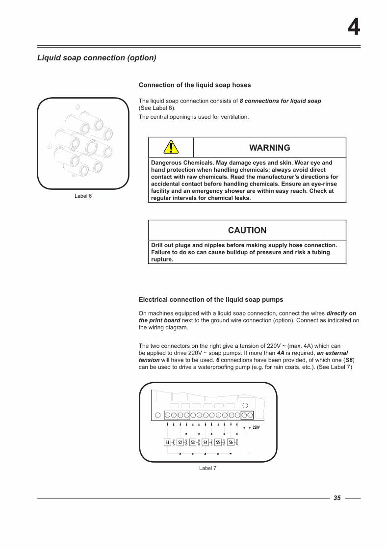
The liquid soap connection consists of 8 connections for liquid soap (See Label 6).The central opening is used for ventilation.
Liquid soap connection (option)
Connection of the liquid soap hoses
WARNINGDangerous Chemicals. May damage eyes and skin. Wear eye and hand protection when handling chemicals; always avoid direct contact with raw chemicals. Read the manufacturer’s directions for accidental contact before handling chemicals. Ensure an eye-rinse facility and an emergency shower are within easy reach. Check at regular intervals for chemical leaks.
CAUTIONDrill out plugs and nipples before making supply hose connection. Failure to do so can cause buildup of pressure and risk a tubing rupture.
Electrical connection of the liquid soap pumps
On machines equipped with a liquid soap connection, connect the wires directly on the print board next to the ground wire connection (option). Connect as indicated on the wiring diagram.
The two connectors on the right give a tension of 220V ~ (max. 4A) which can be applied to drive 220V ~ soap pumps. If more than 4A is required, an external tension will have to be used. 6 connections have been provided, of which one (S6) can be used to drive a waterproofing pump (e.g. for rain coats, etc.). (See Label 7)
Label 8
Label 9
Label 10
4
36
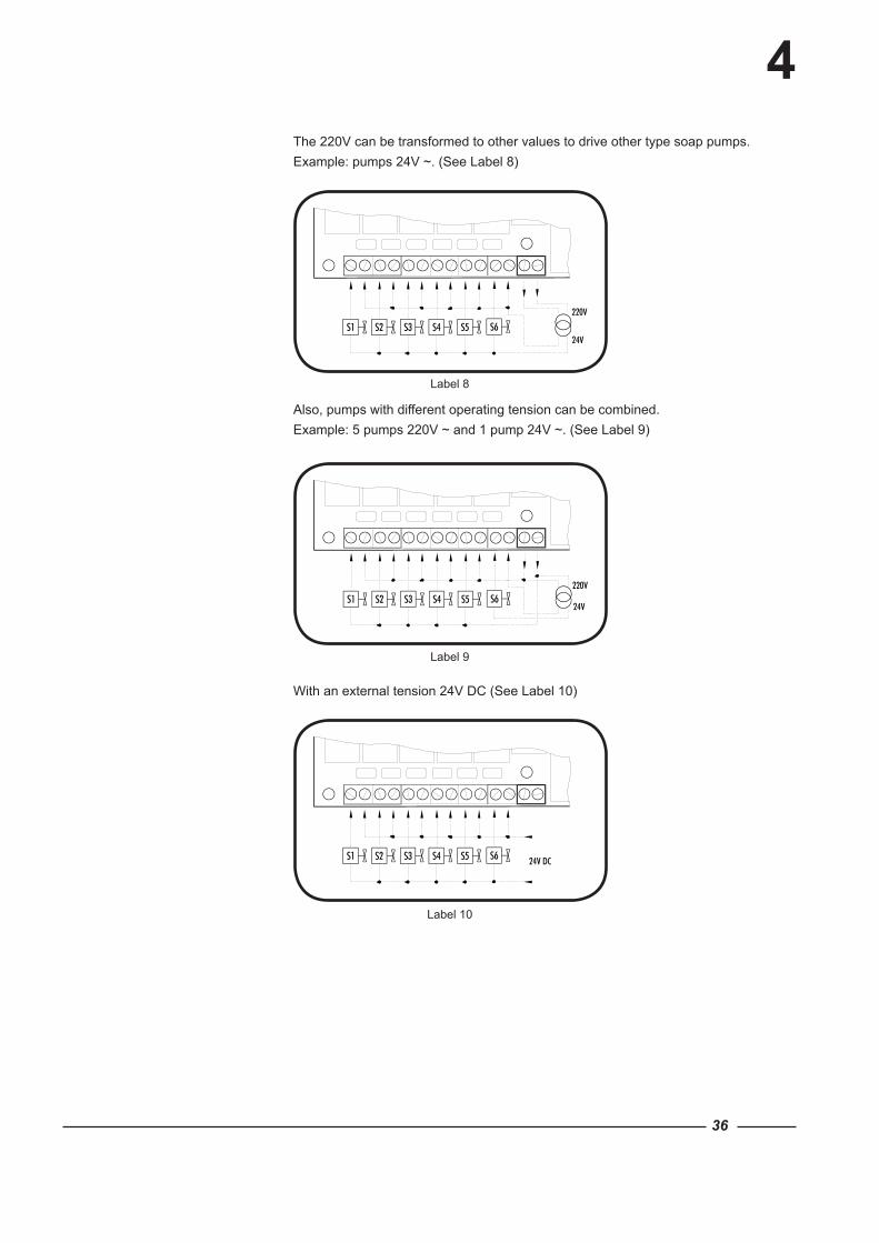
The 220V can be transformed to other values to drive other type soap pumps.Example: pumps 24V ~. (See Label 8)
Also, pumps with different operating tension can be combined.Example: 5 pumps 220V ~ and 1 pump 24V ~. (See Label 9)
With an external tension 24V DC (See Label 10)
Label 11 Label 12 Label 13
Label 14
4
A
37
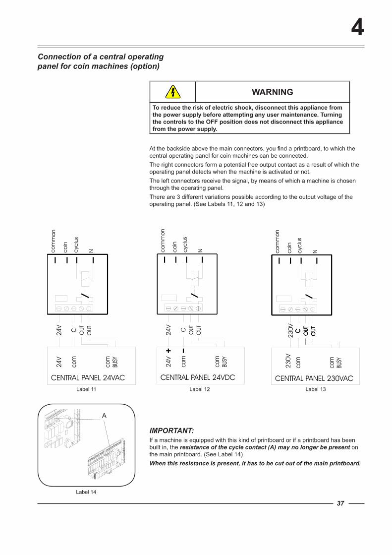
Connection of a central operating panel for coin machines (option)
WARNINGTo reduce the risk of electric shock, disconnect this appliance from the power supply before attempting any user maintenance. Turning the controls to the OFF position does not disconnect this appliance from the power supply.
At the backside above the main connectors, you find a printboard, to which the central operating panel for coin machines can be connected.The right connectors form a potential free output contact as a result of which the operating panel detects when the machine is activated or not.The left connectors receive the signal, by means of which a machine is chosen through the operating panel.There are 3 different variations possible according to the output voltage of the operating panel. (See Labels 11, 12 and 13)
IMPORTANT:If a machine is equipped with this kind of printboard or if a printboard has been built in, the resistance of the cycle contact (A) may no longer be present on the main printboard. (See Label 14)When this resistance is present, it has to be cut out of the main printboard.
5
2345 3 1
6
7
7
7
38
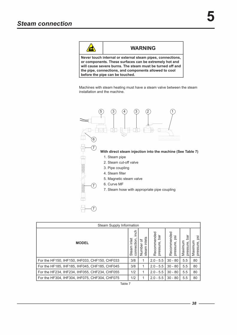
Steam connection
Machines with steam heating must have a steam valve between the steam installation and the machine.
WARNINGNever touch internal or external steam pipes, connections, or components. These surfaces can be extremely hot and will cause severe burns. The steam must be turned off and the pipe, connections, and components allowed to cool before the pipe can be touched.
Steam Supply Information
MODEL
Ste
am in
let
conn
ectio
n, in
chN
umbe
r of
stea
m in
lets
Rec
omm
ende
d pr
essu
re, b
ar
Rec
omm
ende
d pr
essu
re, p
si
Max
imum
pr
essu
re, b
arM
axim
um
pres
sure
, psi
For the HF150, IHF150, IHF033, CHF150, CHF033 3/8 1 2.0 - 5.5 30 - 80 5.5 80For the HF185, IHF185, IHF045, CHF185, CHF045 3/8 1 2.0 - 5.5 30 - 80 5.5 80For the HF234, IHF234, IHF055, CHF234, CHF055 1/2 1 2.0 - 5.5 30 - 80 5.5 80For the HF304, IHF304, IHF075, CHF304, CHF075 1/2 1 2.0 - 5.5 30 - 80 5.5 80
With direct steam injection into the machine (See Table 7)1. Steam pipe2. Steam cut-off valve3. Pipe coupling4. Steam filter5. Magnetic steam valve6. Curve MF7. Steam hose with appropriate pipe coupling
Table 7
6
Label 15 Label 16
39
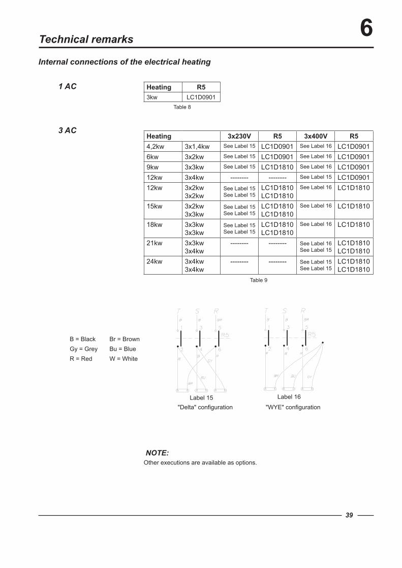
Internal connections of the electrical heating
NOTE:Other executions are available as options.
3 AC
1 AC
Technical remarks
Heating 3x230V R5 3x400V R54,2kw 3x1,4kw See Label 15 LC1D0901 See Label 16 LC1D09016kw 3x2kw See Label 15 LC1D0901 See Label 16 LC1D09019kw 3x3kw See Label 15 LC1D1810 See Label 16 LC1D090112kw 3x4kw -------- -------- See Label 15 LC1D090112kw 3x2kw
3x2kwSee Label 15 See Label 15
LC1D1810 LC1D1810
See Label 16 LC1D1810
15kw 3x2kw 3x3kw
See Label 15 See Label 15
LC1D1810 LC1D1810
See Label 16 LC1D1810
18kw 3x3kw 3x3kw
See Label 15 See Label 15
LC1D1810 LC1D1810
See Label 16 LC1D1810
21kw 3x3kw 3x4kw
-------- -------- See Label 16 See Label 15
LC1D1810 LC1D1810
24kw 3x4kw 3x4kw
-------- -------- See Label 15 See Label 15
LC1D1810 LC1D1810
Heating R53kw LC1D0901
B = Black Br = BrownGy = Grey Bu = BlueR = Red W = White
Table 8
Table 9
"Delta" configuration "WYE" configuration
7
40
Maintenance instruction of the machine
Clean the entire cabinet of the machine regularly and remove all traces of soap, etc....
Remove all detergent residue in the soap dispenser with hot water. Clean the door gasket and remove all detergents and other products. Shut off the main water, steam, and power connections at the end of each day.
Do not change the setting of the water inlet taps on boiler fed machines once these have been installed.
It is recommended to leave the door and soap dispenser open after use, to ventilate the machine.
Check for proper door lock operation on a daily basis.
General maintenance
The V-belts of the motors should be retightened after two to three months when first used. This is necessary because these belts are subject to a one-time stretching when first used. If this is not done, the belt starts to slip after a few months and will break shortly afterwards.
Check the water inlet filters to make sure they are not blocked by calcification. Check the drain valve for obstructions. If a machine frequently skips the final spin, check whether the probe of the out of
balance switch is still in the appropriate position, that is horizontally centered and vertically 1/3 from the bottom inside the window. (When the drum is empty).
Lubricate the bearings after every 200 hours of operation or replace the automatic lubricator annually.
Periodical maintenance
Clean AC drive filter: a. Snap off external plastic cover which contains filter. b. Remove foam filter from cover. c. Wash filter with warm water and allow to air dry. Filter can be vacuumed clean.
End of day
WARNINGTo reduce the risk of electric shock, disconnect this appliance from the power supply before attempting any user maintenance. Turning the controls to the OFF position does not disconnect this appliance from the power supply.Before starting wiring or inspection, power must be switched OFF, check to make sure that the operation panel indicator is off. Any person who is involved in wiring or inspection shall wait for at least 10 minutes after the power supply has been switched OFF and check that there is no residual voltage using a tester or the like. The capacitor of the inverter or the EMC filter is charged with a high voltage for some time after power OFF, and it is dangerous.
7
41
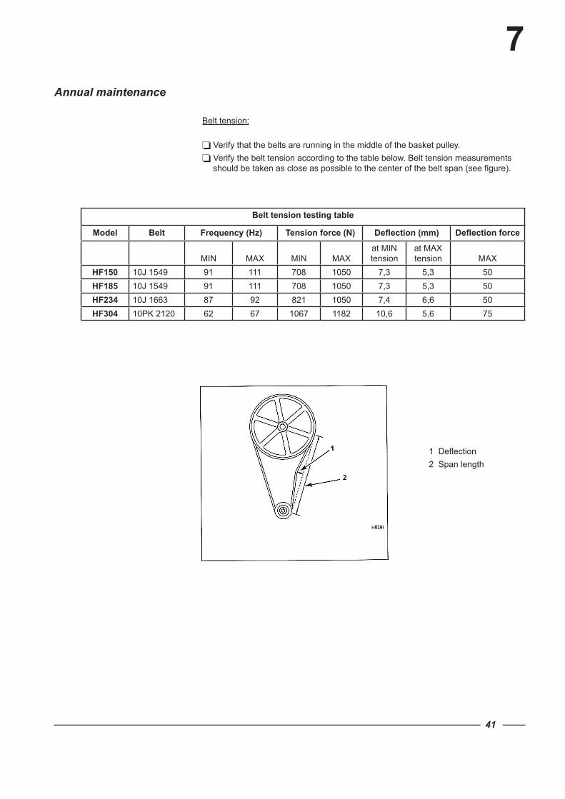
Verify that the belts are running in the middle of the basket pulley. Verify the belt tension according to the table below. Belt tension measurements
should be taken as close as possible to the center of the belt span (see figure).
Annual maintenance
Belt tension:
Belt tension testing table
Model Belt Frequency (Hz) Tension force (N) Deflection (mm) Deflection force
MIN
MAX
MIN
MAX
at MIN tension
at MAX tension
MAX
HF150 10J 1549 91 111 708 1050 7,3 5,3 50HF185 10J 1549 91 111 708 1050 7,3 5,3 50HF234 10J 1663 87 92 821 1050 7,4 6,6 50HF304 10PK 2120 62 67 1067 1182 10,6 5,6 75
1 Deflection2 Span length
8
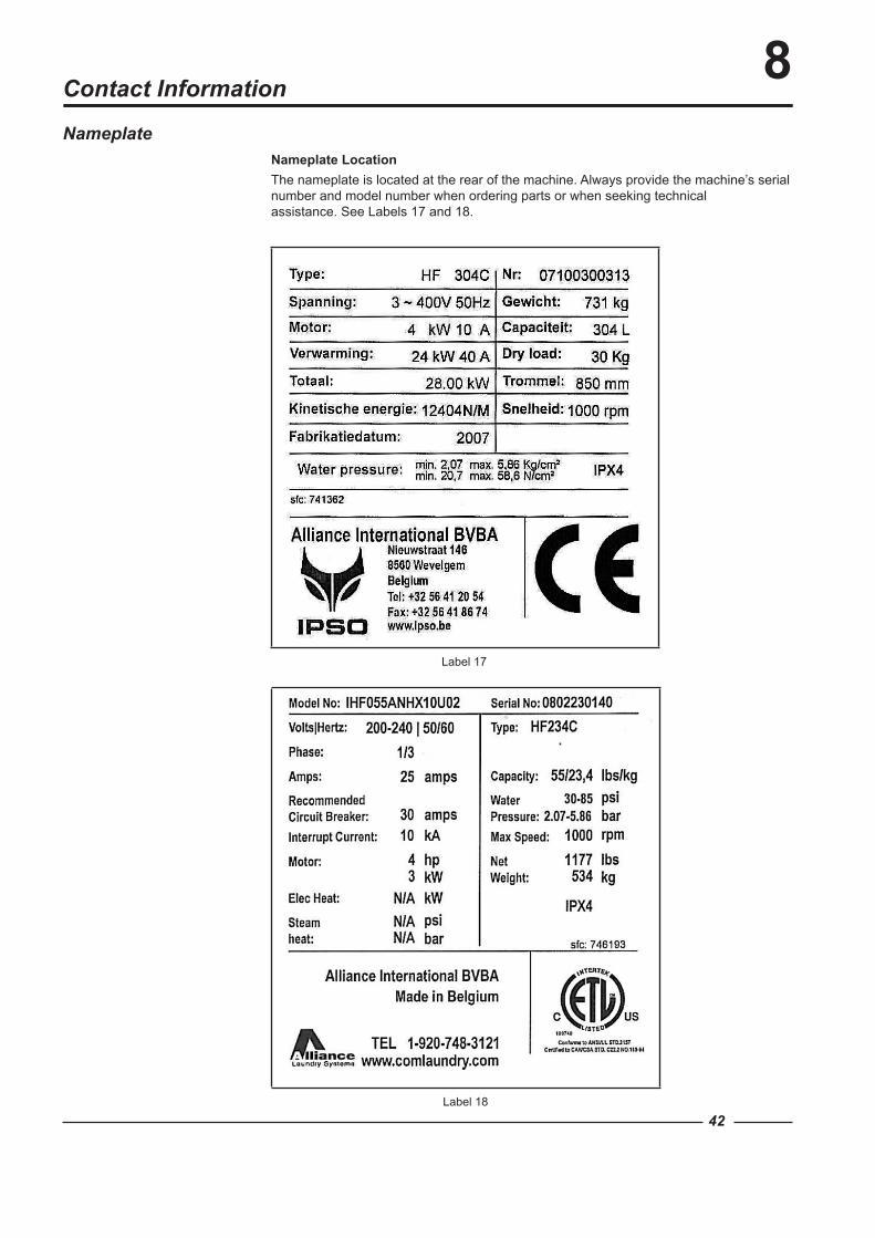
Label 17
Label 18
42
Contact Information
NameplateNameplate LocationThe nameplate is located at the rear of the machine. Always provide the machine’s serial number and model number when ordering parts or when seeking technical assistance. See Labels 17 and 18.
8
43
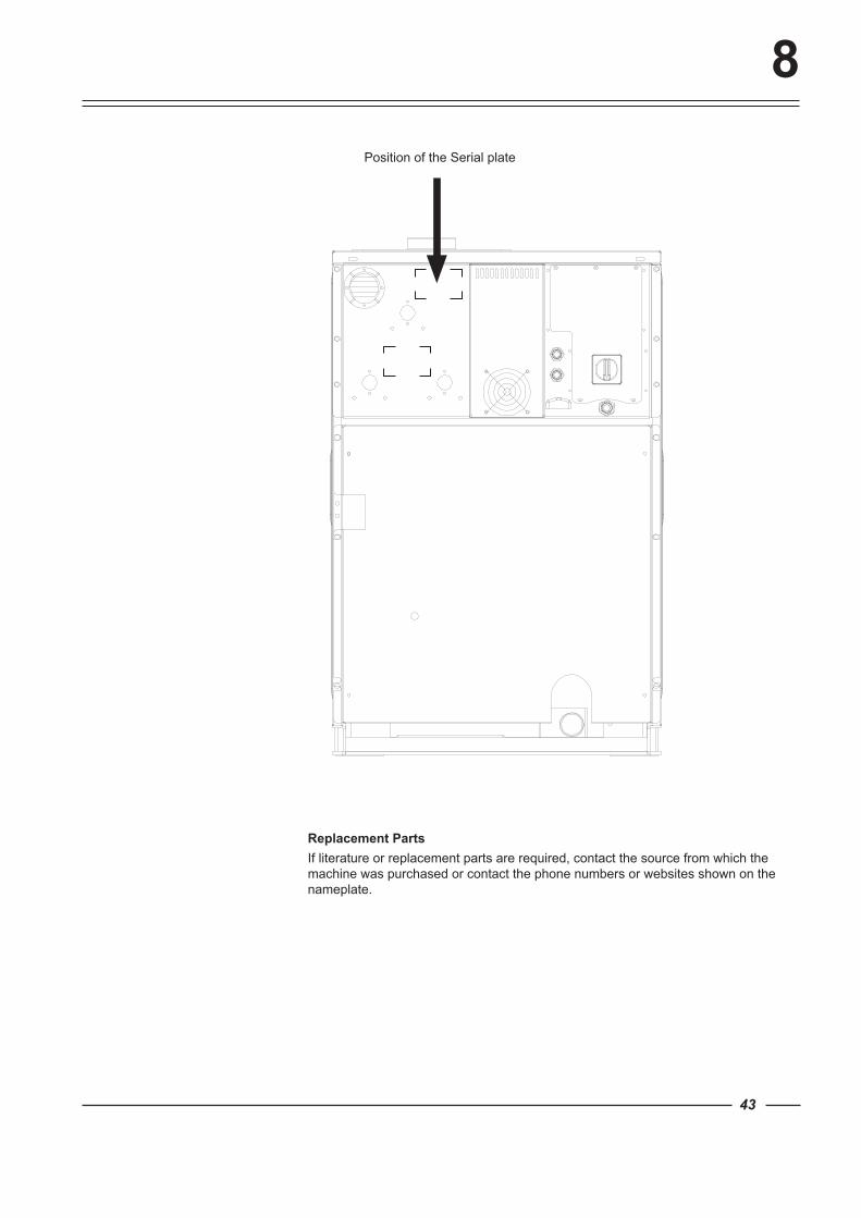
Replacement PartsIf literature or replacement parts are required, contact the source from which the machine was purchased or contact the phone numbers or websites shown on the nameplate.
Position of the Serial plate
9
44
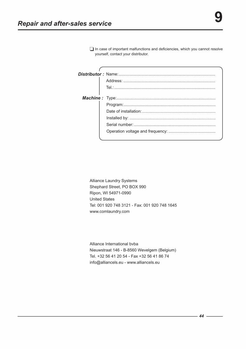
In case of important malfunctions and deficiencies, which you cannot resolve yourself, contact your distributor.
Repair and after-sales service
Machine : Type: ......................................................................................Program: ................................................................................Date of installation: ................................................................Installed by: ...........................................................................Serial number: .......................................................................Operation voltage and frequency: .........................................
Distributor : Name: ....................................................................................Address: ................................................................................Tel.: ........................................................................................
Alliance Laundry SystemsShephard Street, PO BOX 990Ripon, WI 54971-0990United StatesTel: 001 920 748 3121 - Fax: 001 920 748 1645www.comlaundry.com
Alliance International bvbaNieuwstraat 146 - B-8560 Wevelgem (Belgium)Tel. +32 56 41 20 54 - Fax +32 56 41 86 [email protected] - www.alliancels.eu