Embed Size (px)
Citation preview
Instruction manual
Washer Extractors
Technical specificationsInstallation instructionsMaintenance
Part No. D1278
July 2010
HM270 - HM330HM490 - HM670

-1-
These technical documents contain information that is privileged and confidential.
You are hereby notified that any disclosure or copying is strictly prohibited. We will proceed against any breach of this condition.
Les documents techniques comportent des informations confidentielles.
Nous tenons à porter à votre connaissance qu‟il est interdit de dévoiler and copier ces documents and que nous engagerons des
procédures contre les auteurs des dites copies.
-2-
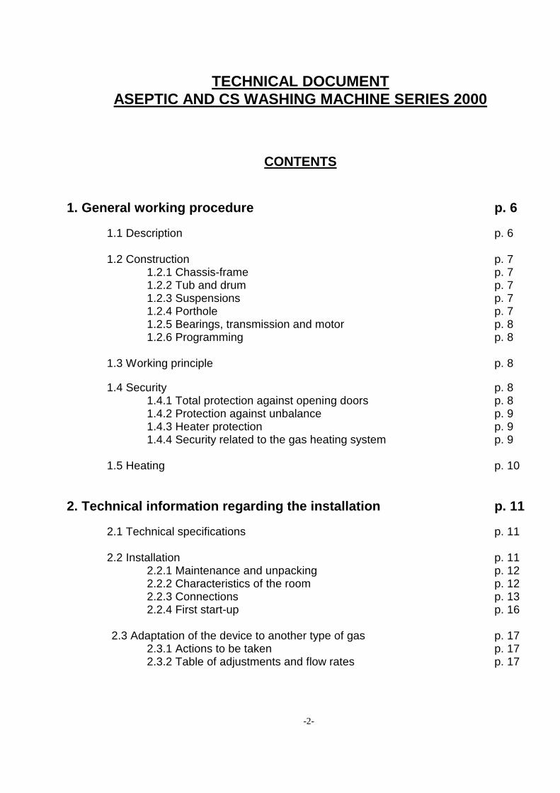
TECHNICAL DOCUMENT
ASEPTIC AND CS WASHING MACHINE SERIES 2000
CONTENTS
1. General working procedure p. 6
1.1 Description p. 6 1.2 Construction p. 7 1.2.1 Chassis-frame p. 7 1.2.2 Tub and drum p. 7 1.2.3 Suspensions p. 7 1.2.4 Porthole p. 7 1.2.5 Bearings, transmission and motor p. 8 1.2.6 Programming p. 8 1.3 Working principle p. 8
1.4 Security p. 8 1.4.1 Total protection against opening doors p. 8 1.4.2 Protection against unbalance p. 9 1.4.3 Heater protection p. 9 1.4.4 Security related to the gas heating system p. 9 1.5 Heating p. 10
2. Technical information regarding the installation p. 11
2.1 Technical specifications p. 11 2.2 Installation p. 11 2.2.1 Maintenance and unpacking p. 12 2.2.2 Characteristics of the room p. 12 2.2.3 Connections p. 13 2.2.4 First start-up p. 16 2.3 Adaptation of the device to another type of gas p. 17 2.3.1 Actions to be taken p. 17 2.3.2 Table of adjustments and flow rates p. 17
-3-
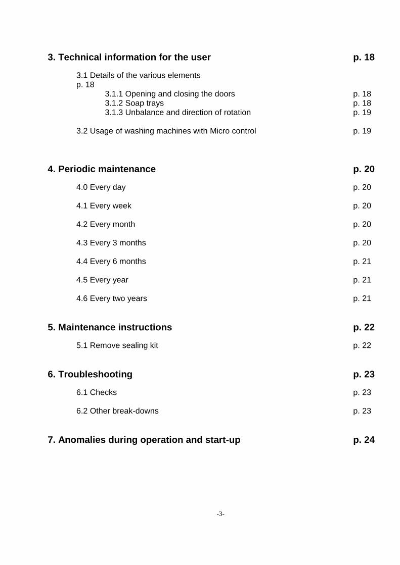
3. Technical information for the user p. 18
3.1 Details of the various elements p. 18 3.1.1 Opening and closing the doors p. 18 3.1.2 Soap trays p. 18 3.1.3 Unbalance and direction of rotation p. 19 3.2 Usage of washing machines with Micro control p. 19
4. Periodic maintenance p. 20
4.0 Every day p. 20 4.1 Every week p. 20 4.2 Every month p. 20 4.3 Every 3 months p. 20 4.4 Every 6 months p. 21 4.5 Every year p. 21 4.6 Every two years p. 21
5. Maintenance instructions p. 22
5.1 Remove sealing kit p. 22
6. Troubleshooting p. 23
6.1 Checks p. 23
6.2 Other break-downs p. 23
7. Anomalies during operation and start-up p. 24
-4-
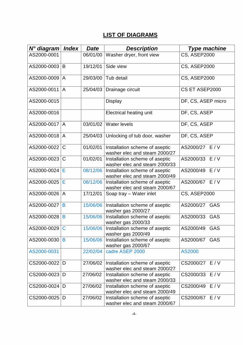
LIST OF DIAGRAMS
N° diagram Index Date Description Type machine AS2000-0001 06/01/00 Washer dryer, front view CS, ASEP2000
AS2000-0003 B 19/12/01 Side view CS, ASEP2000
AS2000-0009 A 29/03/00 Tub detail CS, ASEP2000
AS2000-0011 A 25/04/03 Drainage circuit CS ET ASEP2000
AS2000-0015 Display DF, CS, ASEP micro
AS2000-0016 Electrical heating unit DF, CS, ASEP
AS2000-0017 A 03/01/02 Water levels DF, CS, ASEP
AS2000-0018 A 25/04/03 Unlocking of tub door, washer DF, CS, ASEP
AS2000-0022 C 01/02/01 Installation scheme of aseptic washer elec and steam 2000/27
AS2000/27 E / V
AS2000-0023 C 01/02/01 Installation scheme of aseptic washer elec and steam 2000/33
AS2000/33 E / V
AS2000-0024 E 08/12/06 Installation scheme of aseptic washer elec and steam 2000/49
AS2000/49 E / V
AS2000-0025 E 08/12/06 Installation scheme of aseptic washer elec and steam 2000/67
AS2000/67 E / V
AS2000-0026 A 17/12/01 Soap tray – Water inlet CS, ASEP2000
AS2000-0027 B 15/06/06 Installation scheme of aseptic washer gas 2000/27
AS2000/27 GAS
AS2000-0028 B 15/06/06 Installation scheme of aseptic washer gas 2000/33
AS2000/33 GAS
AS2000-0029 C 15/06/06 Installation scheme of aseptic washer gas 2000/49
AS2000/49 GAS
AS2000-0030 B 15/06/06 Installation scheme of aseptic washer gas 2000/67
AS2000/67 GAS
AS2000-0031 22/02/04 cadre ASEP 2000 AS2000
CS2000-0022 D 27/06/02 Installation scheme of aseptic washer elec and steam 2000/27
CS2000/27 E / V
CS2000-0023 D 27/06/02 Installation scheme of aseptic washer elec and steam 2000/33
CS2000/33 E / V
CS2000-0024 D 27/06/02 Installation scheme of aseptic washer elec and steam 2000/49
CS2000/49 E / V
CS2000-0025 D 27/06/02 Installation scheme of aseptic washer elec and steam 2000/67
CS2000/67 E / V
-5-
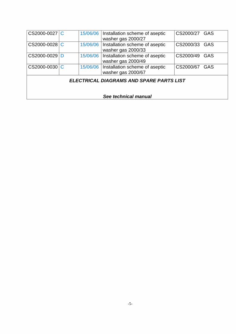
CS2000-0027 C 15/06/06 Installation scheme of aseptic washer gas 2000/27
CS2000/27 GAS
CS2000-0028 C 15/06/06 Installation scheme of aseptic washer gas 2000/33
CS2000/33 GAS
CS2000-0029 D 15/06/06 Installation scheme of aseptic washer gas 2000/49
CS2000/49 GAS
CS2000-0030 C 15/06/06 Installation scheme of aseptic washer gas 2000/67
CS2000/67 GAS
ELECTRICAL DIAGRAMS AND SPARE PARTS LIST
See technical manual
-6-
1. GENERAL WORKING PROCEDURE
1.1 Description
Correct usage in accordance with design : The dirty laundry is loaded into the front part of the machine and the clean laundry is unloaded from the rear part of the machine, using portholes situated opposite to the loading ports (for the Aseptic machines) or into the front part of the machine (for the CS machines). When a separating wall os constructed at the middle plane of the machine this will then avoid any contact between the dirty and the clean laundry.
Simple usage : loading and unloading of the laundry through 1 or 2 large ports opening by 180°.
Easy-to-use programs :
o Control of the machine by a microprocessor with 5 standard programs - washing types. It provides the possibility to create 28 other programs according to your requirements.
No concrete base is required, however a stable and level floor is absolutely necessary.
No vibrations are transmitted to the floor.
The machine only requires one electrical connection, one connection for the heating system of the machine (electricity or vapour or gas) and one channel for the drainage of used water.
Various types of detergents may be used : Classical detergent in powder form or liquid detergent supplied by a dosing pump.
Note : the supplier of the liquid detergents must carry out the adaptation of the dosing pumps and their electrical connection (since the system is specific for each type of product).
-7-
1.2 Construction 1.2.1 Chassis - frame
Mechanically soldered frame of hot de-scaled steel plating, protected against oxidation by phosphation, and covered with epoxy paint.
Protection panels in stainless steel plating with 1,5 mm thickness.
The design of the lower part of each tub port inhibits the laundry from slipping in-between the tub and the drum.
1.2.2 Tub and drum
The tub consists of a rolled stainless steel plate, closed at its extremities by 2 flanges, also stainless steel. The tub flanges are bolted to the tub and a seal assures waterproofing.
The drum consists of a perforated and pressed stainless steel plate. The plate is then rolled and nested in two bead plates, also stainless steel. 4 beaters mounted peripherally around the interior allow the laundry to be stirred correctly. This assembly is held together by 4 tension rods that traverse the drum from one end to the other.
1.2.3 Suspensions
The tub - drum assembly is suspended by 12 springs that are attached to the frame and held in place by four shockbreakers, thus absorbing all vibration. The drum is held laterally by four frictional gliders that further limit the movement of the assembly.
1.2.4 Porthole The large-size portholes are of stainless steel and equipped with SECURIT panes of tempered glass. Thus they permit a visual control of the washing operation.
-8-
1.2.5 Bearings, transmission and motor
The connecting rod bearings are waterproof and have a hardened steel base.
The transmission consists of several belts, providing a driving mechanism without slippage.
The asynchronous motor with variable frequency provides a gradual acceleration, without shocks, which avoids drawing a large current when initiating centrifugal motion.
1.2.6 Programming
Of the integral type with a microprocessor, regulation of :
4 soap trays.
Admission of hot, cold and/or soft water.
bath levels adjustable.
Temperature adjustable from 0 to 90°C with microprocessor.
Reduced mechanical washing motion for delicate laundry.
Normal mechanical washing motion.
Intermediate and final centrifuge.
1.3 Working principle
The following operations: loading the dirty laundry, loading the various detergents, and starting and controlling the operations by means of the control panel, are all done on the "dirty laundry" side of the machine. Once the program is finished, the drum ports are automatically aligned with the "clean laundry" side for the Aseptic machines (the laundry may then be unloaded on the other side of the separation wall, in another room, without risking contamination of the clean laundry by contact with the dirty laundry) or “dirty laundry” side (for the CS machines).
1.4 Security 1.4.1 Total protection against opening doors This protection is designed to prevent accidents that might be caused by opening a porthole while the drum is rotating.
Depending on the machine type, either one or two magnetic latches inhibit the opening of the porthole(s) of the tub.
The microprocessor orders their release automatically.
After centrifuging the release of the latches is retarded by about 90 seconds.
In case of an electrical outage and after verifying that the drum has come to a complete stop, it is possible to unlock the doors through an opening that has been spared out for this purpose in the casing of the lock mechanism.
-9-
1.4.2 Protection against unbalance The suspended aseptic or CS machines are fitted with one or two unbalance protections, according to their load capacity. These avoid excessive oscillations caused by a strong unbalance by interrupting the centrifugal motion. Effect of the protections in case of a strong unbalance
During the final centrifuge, the centrifugal motion is interrupted and the drainage is maintained, but the cycle is frozen. The message “E9 or unbalance fault” is shown on the display. One must restart the cycle and move fast forward through the program to arrive at the centrifuge phase again.
1.4.3 Heater protection
The bath heating system is not switched on unless the pressure meter, installed for this purpose, detects the correct water level.
1.4.4 Security related to the gas heating system 4 security systems guarantee the correct operation of the system.
When no flame is detected in the burner, the igniter and control plug of the flame causes the closure of the electronic valve in the gas feed, while message “E13” appears on the display.
After waiting for about 20 seconds you may then restart the system by pressing the gas restarting pushbutton (the same as the gas fault indicator) for machine equipped with MAGELIS or by a key combinaison for machine with D1500 . If the default appears again, one of the following faults has occurred :
o No gas feed : check whether the gas feed valves are open. o Igniter plug broken.
The thermostat « chimney obstructed » interrupts the power supply to the command module, in case the chimney is obstructed, and informs you of this fault on the terminal display showing « E10 or chimney obstructed ». After several minutes, you may restart the cycle by pressing « start ». Check your chimney when the fault persists.
The thermostat « heating security » also interrupts the command module when the temperature in the heater is abnormal and informs you of this fault on the terminal display showing « E11 or heating security ».
The thermostat « water failure security » also interrupts the command module when the heating element overheats and informs you of this fault on the terminal display showing « E12 or water failure security ».
When a fault occurs in the water circulation pump, the power supply of the command module is interrupted and the indicator « pump fault » lights up. When the faults persist, check with qualified technical service.
-10-
1.5 Heating 3 heating methods are available, providing the flexibility to adapt the machine to the available energy supply.
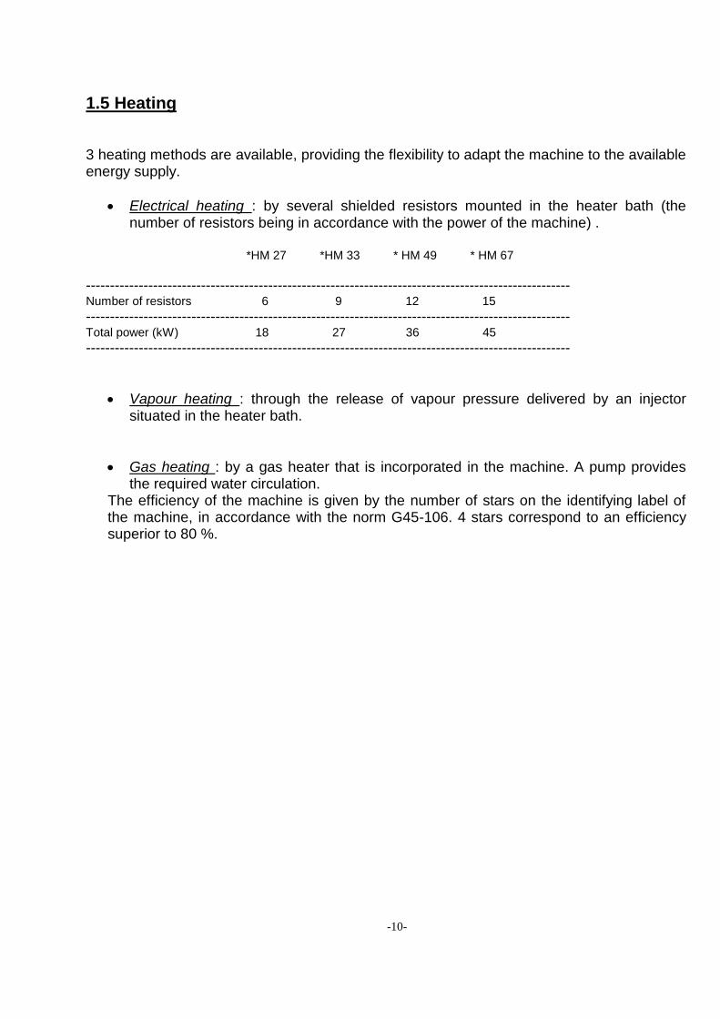
Electrical heating : by several shielded resistors mounted in the heater bath (the number of resistors being in accordance with the power of the machine) .
*HM 27 *HM 33 * HM 49 * HM 67
----------------------------------------------------------------------------------------------------- Number of resistors 6 9 12 15
----------------------------------------------------------------------------------------------------- Total power (kW) 18 27 36 45
-----------------------------------------------------------------------------------------------------
Vapour heating : through the release of vapour pressure delivered by an injector situated in the heater bath.
Gas heating : by a gas heater that is incorporated in the machine. A pump provides the required water circulation.
The efficiency of the machine is given by the number of stars on the identifying label of the machine, in accordance with the norm G45-106. 4 stars correspond to an efficiency superior to 80 %.
-11-
2. TECHNICAL INFORMATION REGARDING THE INSTALLATION
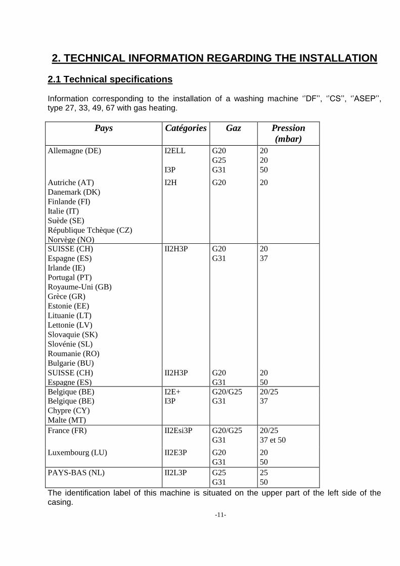
2.1 Technical specifications Information corresponding to the installation of a washing machine „‟DF‟‟, „‟CS‟‟, „‟ASEP‟‟, type 27, 33, 49, 67 with gas heating.
Pays Catégories Gaz Pression
(mbar)
Allemagne (DE) I2ELL
I3P
G20
G25
G31
20
20
50
Autriche (AT)
Danemark (DK)
Finlande (FI)
Italie (IT)
Suède (SE)
République Tchèque (CZ)
Norvège (NO)
I2H G20 20
SUISSE (CH)
Espagne (ES)
Irlande (IE)
Portugal (PT)
Royaume-Uni (GB)
Grèce (GR)
Estonie (EE)
Lituanie (LT)
Lettonie (LV)
Slovaquie (SK)
Slovénie (SL)
Roumanie (RO)
Bulgarie (BU)
II2H3P G20
G31
20
37
SUISSE (CH)
Espagne (ES)
II2H3P G20
G31
20
50
Belgique (BE) I2E+ G20/G25 20/25
Belgique (BE)
Chypre (CY)
Malte (MT)
I3P G31 37
France (FR) II2Esi3P G20/G25
G31
20/25
37 et 50
Luxembourg (LU) II2E3P G20
G31
20
50
PAYS-BAS (NL) II2L3P G25
G31
25
50
The identification label of this machine is situated on the upper part of the left side of the casing.
-12-
2.2 Installation
Attention : the machine must only be installed, adjusted and started up by a team of technicians of the manufacturer or by technicians or resellers that are recognised by the manufacturer. Likewise, it is strongly recommended that the client be present during the installation and the first trials. The installation of the device must be in accordance with the current regulations and normatives, and in a room with sufficient ventilation. The flow of fresh air required for combustion is 90 cubic metres per hour when gas heating is used.
2.2.1 Maintenance and unpacking
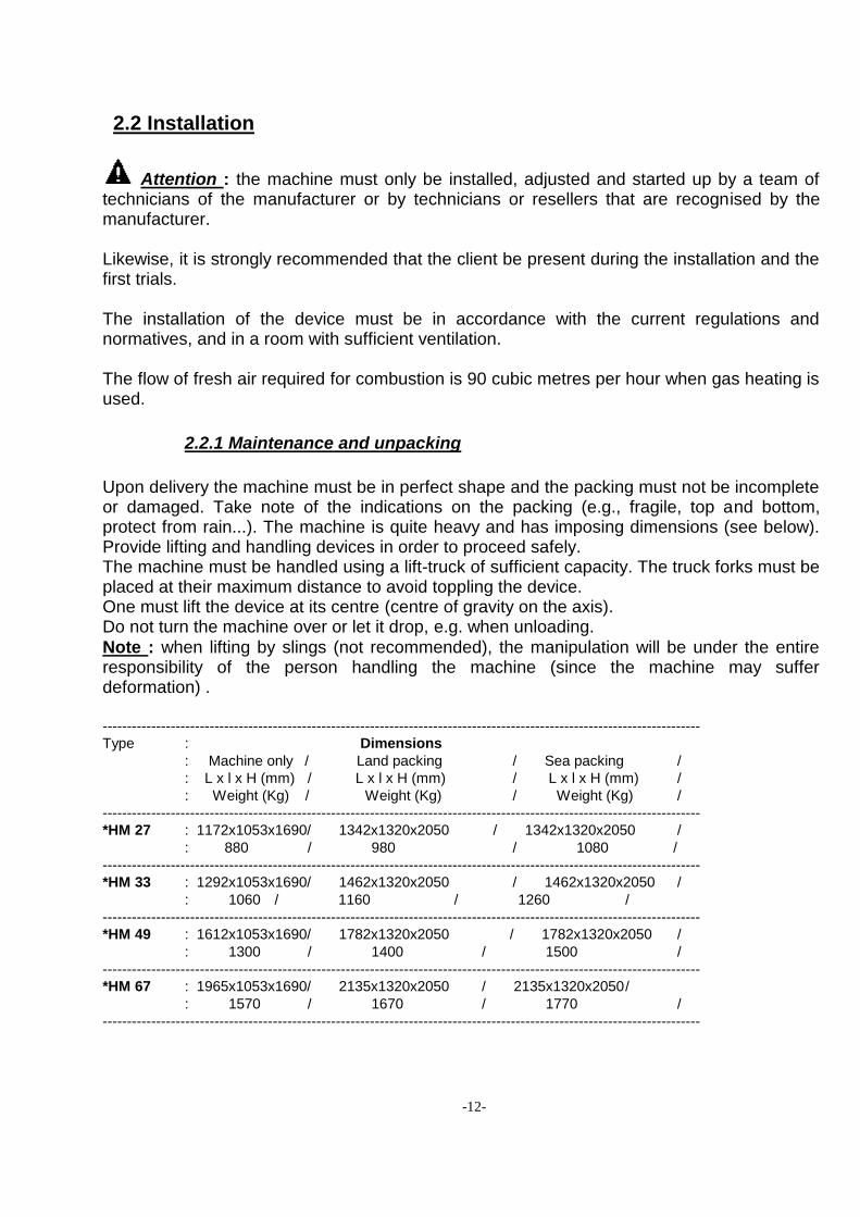
Upon delivery the machine must be in perfect shape and the packing must not be incomplete or damaged. Take note of the indications on the packing (e.g., fragile, top and bottom, protect from rain...). The machine is quite heavy and has imposing dimensions (see below). Provide lifting and handling devices in order to proceed safely. The machine must be handled using a lift-truck of sufficient capacity. The truck forks must be placed at their maximum distance to avoid toppling the device. One must lift the device at its centre (centre of gravity on the axis). Do not turn the machine over or let it drop, e.g. when unloading.
Note : when lifting by slings (not recommended), the manipulation will be under the entire responsibility of the person handling the machine (since the machine may suffer deformation) . ---------------------------------------------------------------------------------------------------------------------------
Type : Dimensions
: Machine only / Land packing / Sea packing /
: L x l x H (mm) / L x l x H (mm) / L x l x H (mm) /
: Weight (Kg) / Weight (Kg) / Weight (Kg) /
---------------------------------------------------------------------------------------------------------------------------
*HM 27 : 1172x1053x1690/ 1342x1320x2050 / 1342x1320x2050 /
: 880 / 980 / 1080 /
---------------------------------------------------------------------------------------------------------------------------
*HM 33 : 1292x1053x1690/ 1462x1320x2050 / 1462x1320x2050 /
: 1060 / 1160 / 1260 /
---------------------------------------------------------------------------------------------------------------------------
*HM 49 : 1612x1053x1690/ 1782x1320x2050 / 1782x1320x2050 /
: 1300 / 1400 / 1500 /
---------------------------------------------------------------------------------------------------------------------------
*HM 67 : 1965x1053x1690/ 2135x1320x2050 / 2135x1320x2050 /
: 1570 / 1670 / 1770 /
---------------------------------------------------------------------------------------------------------------------------
-13-
2.2.2 Characteristics of the room
The machine must be installed in a very well ventilated room with correct lighting and
a temperature in the range from -10 to + 40°C (temperature limits for the electronic frequency regulator of the driving motor) .
Sufficient space must be left around the machine to allow for its correct functioning.
On each side sufficient space must be left in front of the portholes so that the machine operator can work correctly and without danger.
Levelling should be carried out correctly on a hard and stable floor surface, capable of
supporting the considerable weight of the machine (between 900 and 1600 kg on 1,2
to 2,2 m²). The floor must at least be able to support 1100 kg per m² for the installation of such a machine.
Correct levelling also guarantees an optimum performance of the suspensions and the water bath, which is balanced horizontally. All machine types should further be fixed to the floor by self-boring plugs of size M12. Indeed, when an important unbalance occurs, the machine may move slightly, no longer be perfectly horizontal (see drawing), and exert forces on the feeding and draining tubes. With this type of machine it is possible to insert wedges between the frame and the floor in order to level it.
Construction work required :
No concrete support is needed.
No vibration is transmitted to the floor. To evacuate used water, a drain of at least 150 x 150 mm must be located right under the machine. 2.2.3 Connections
Water supply connection :
All our machines are fitted with two water supply connections (hot and cold water). Please consult us for the optional soft water connection. For the machines with gas heating, it is imperative to ensure the correct operation of the boiler, to supply the water for washing step with a maximum TH of 10°. A higher TH will involve an irremediable clogging of the boiler.
-14-
Install two pipes (hot and cold water) vertically behind the machine; install two blocking valves in an accessible location. Install a filter in each pipe, upstream from the blocking valves. The pressure must be between 2 and 6 bars; install a motion absorber system as well as an escape valve to handle high water pressure. Diameter of the tubing Machine type diameter of the water connection *HM 27 20/27 (3/4") *HM 33 20/27 (3/4") *HM 49 20/27 (3/4") *HM 67 26/34 (1") *HM 27 *HM 33 *HM 49 *HM 67
Water consumption (litres) ------------------------------------------------------------------- prewash 50 65 90 130
wash 50 65 90 130
Rinse 81 100 150 200
Cycle 343 430 630 860
Water flow rate: 160 L/min.
Drain connection : All machine types have 1 drain of diameter 80 (drainage of the tub). The minimum cross section of the used water drain below the machine should be respected (at least 150 x 150 mm).
Electrical connection : In all cases the electrical power connection consists either of a cable with 4 wires, 230 V, three-phase or of a cable with 5 wires, 400 V, three-phase. Wire colours THREE 380 V + N + T Black - black - brown ...….... Phases Blue ..................................... Neutral Green / yellow ..................... Earth THREE 220 V + T Black - brown - blue ........... Phases Green / yellow..................... Earth
-15-
Important : Install an additional upstream fuse cabinet. Furthermore, install a residual current operated circuit breaker for the general protection of your launderette against electrical faults. These installations must be in accordance with valid regulations.
Note : fuses protect the control and power circuitry.
Table : motor power --------------------------------------------------------------------------------------------------------------------------- *HM 27 *HM 33 *HM 49 *HM 67
-------------------------------------------------------------------------------------------------------- Power in kW 4 4 5.5 5.5
-------------------------------------------------------------------------------------------------------- Nominal velocity in tr/min 1500 1500 1500 1500
---------------------------------------------------------------------------------------------------------------------------
Electrical heating : The machines that have electrical heating have connections for :
The control and motor circuits.
The heating power circuit.
Table : heating power --------------------------------------------------------------------------------------------------------------------------- *HM 27 *HM 33 *HM 49 *HM 67
230V 400V 230V 400V 230V 400V 230V 400V
----------------------------------------------------------------------------------------------------- Power in kW 18 27 36 45
----------------------------------------------------------------------------------------------------- Inter combined AM 50 32 80 50 100 60 100 60
---------------------------------------------------------------------------------------------------------------------------
Cable section MM2 4x10 5x6 4x10 5x6 4x16 5x6 4x16 5X10
-----------------------------------------------------------------------------------------------------
Vapour connection :
The vapour pressure must be between 5 and 10 bars.
Install a vapour escape valve to avoid overpressure.
Table : vapour consumption ----------------------------------------------------------------------------------------------------- *HM 27 *HM 33 *HM 49 *HM 67
----------------------------------------------------------------------------------------------------- Vapour consumption 18kg/h 26kg/h 40kg/h 60kg/h
----------------------------------------------------------------------------------------------------- Vapour entry connection 3/4" 3/4" 3/4" 3/4"
-----------------------------------------------------------------------------------------------------
-16-
Vent connection :
For security reasons, lead the air tube to the exterior of the room.
Attention : protect the far end of this tube to avoid possible obstruction, which would gravely affect machine operation.
Gas connection Connect the device to the existing gas conducts and install a blocking valve between the device and the rest of the installation. The installation must be in accordance with the valid norms and regulations of the country involved (for France: DTU 61.1). The gas supply conducts must have sufficient dimensions to minimise pressure loss: its diameter must be calculated as a function of its path (length, number of bends...) and the power of the device. Check that the settings of the device correspond to the type and the pressure of the gas of the installation. Connect a manometer to the pressure connection situated on top of the electronic valve module when all burners are on, to check the pressure of the gas feed. The measured gas pressure must be equal to the pressure indicated on the identification label for the used gas type. The gas feed connection is 1 inch in diameter and in agreement with the norm ISO 228/1.
Connection with the exhaust conduct
Place the draught-diverter system supplied with the device between the exit of the heater and the gas exhaust conduct. The tubes that connect with the chimney are of diameter 150 and should be as short as possible. 2.2.4 First start-up
Verify that the machine is stable and level upon first start-up.
Check that all connections and drains are correctly established.
Check that the device is connected to earth correctly.
Check that all switches are in their position 0.
Turn the circuit breaker with guard to position 1.
Check that the pump (gas heating) rotates in the correct direction.
-17-
Note : if the machine turns the wrong way, check the technical service centre of the manufacturer.
Attention : take care not to touch or come close to any moving parts.
Mount all protection panels back on the machine.
2.3 Adaptation of the device to another type of gas 2.3.1 Actions to be taken
Dismount the access panels of the heater on the side of the dirty laundry.
Unscrew the 4 fixing bolts of the gas ramp as well as the bolt of the hose of the gas connection.
Extract the ramp.
Unscrew the injectors and replace them.
Proceed in reverse order to mount the system and check that the gas feed pressure at the entry valves of the module is in agreement with the pressures indicated in the table below (device operating).
Seal the air adjustments with a little paint.
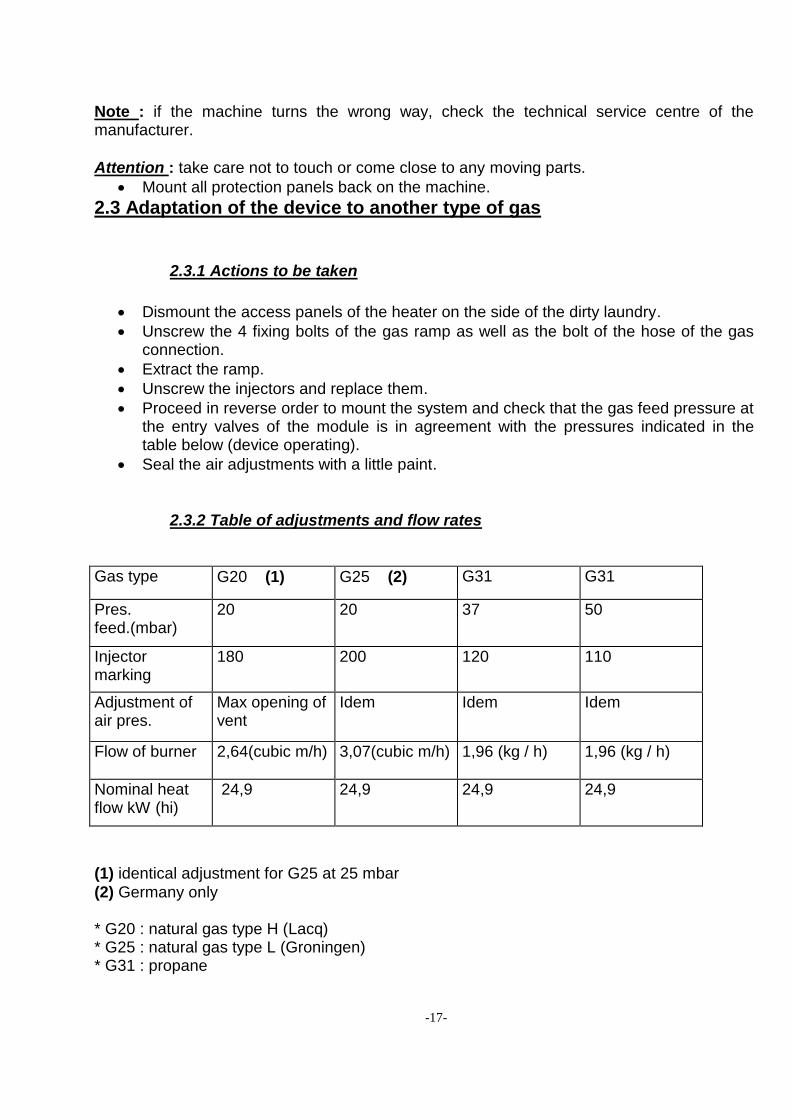
2.3.2 Table of adjustments and flow rates
Gas type G20 (1) G25 (2) G31 G31
Pres. feed.(mbar)
20 20 37 50
Injector marking
180 200 120 110
Adjustment of air pres.
Max opening of vent
Idem Idem Idem
Flow of burner 2,64(cubic m/h) 3,07(cubic m/h) 1,96 (kg / h) 1,96 (kg / h)
Nominal heat flow kW (hi)
24,9 24,9 24,9 24,9
(1) identical adjustment for G25 at 25 mbar
(2) Germany only * G20 : natural gas type H (Lacq) * G25 : natural gas type L (Groningen) * G31 : propane
-18-
3. TECHNICAL INFORMATION FOR THE USER
Note :
The user must not handle parts that are protected by the manufacturer or his representative.
The user must appeal to a qualified installer to adapt the device to a different type of gas.
The exhaust gas evacuation chimney must be swept periodically in accordance with the valid rules of the concerned country.
3.1 Details of the various elements
3.1.1 Opening and closing the doors
Drum portholes
Important : the door locking system of the drum consists of a lock with 2 latches and a rod to move those two latches. Check that the latches are in their correct positions and that the rod is in its holding receptacle before starting a washing cycle (an incorrect door closure will lead to the destruction of the lock parts and may damage the doors). Not following these instructions annuls the guarantee ; the costs of repair of the caused damage will therefore revert automatically to the client. Outer port or porthole
Close the two locks carefully to obtain good waterproofing.
Attention : risk of burning ; please do not touch the glass of the porthole when the machine is functioning, in particular after the heating phase of the washing bath. 3.1.2 Soap trays
Attention : all products used are harmful and must be handled with caution. Read the recommendations of the product suppliers carefully. Before all manipulation : you must use appropriate protective clothing, e.g. gloves, boots, glasses, respiratory masks, etc. Detergent :
-19-
Fill the soap trays with the corresponding products when starting a cycle.
The detergents for washing and pre-washing must be in powder form (or liquid when automatic feeding by a dosing pump is used).
There are several different types of detergent, and some of them are more easily dissolved in water. Consult your supplier, who will provide indications.
Bleach :
5 to 10 g of 12° bleach per litre of water.
Never surpass the lower marking of the siphon of the bleach tray. Softener :
Consult your supplier. The doses vary according to the products used.
3.1.3 Unbalance and direction of rotation When you receive the message “unbalance fault“ before ending a cycle, you must restart the cycle (see Ch. 1.4.2). If the unbalance persists, check the following points :
Machine has insufficient load : Loads must be in the following ranges (dry laundry weight)
*HM 27............. 19 to 27 kg
*HM 33............. 22 to 33 kg
*HM 49............. 38 to 49 kg
*HM 67............. 52 to 67 kg
Water drainage defective.
Long pieces of cloth tangle and create knots.
Heterogeneous load of cloth, differing in type, weights or size.
Poorly adjusted water level : Upper level ... 140 mm Lower level ... 60 mm
Shockbreaker got stuck : the symptom of this problem is an escape of oil on the skirt of the shockbreaker.
Wrong direction of rotation of the centrifuge.
Note : the centrifuge must always switch on with the same velocity and direction as the washing rotation. This rotation is downward when you are on the dirty laundry side of the machine.
-20-
4. PERIODIC MAINTENANCE
4.0 Every day Clean the dust filter located below the tub once a day when using gas heating.
4.1 Every week (0.5 h)
Clean the soap trays.
Clean the machine using a dry or slightly humid cloth (not dripping).
4.2 Every month (1 h)
Check the condition of the shockbreakers (no oil traces should be visible on the outside of the shockbreaker).
Check that the frictional gliders between which the tub-drum assembly is wedged laterally make contact correctly (if the pressure is not sufficient, withdraw a spacer of the frictional arm connection).
Check the condition and waterproofing of the vapour circuit for those machines that are heated by vapour.
Check the working condition of the gas heating system (boiler, safety and filter).
Check the working condition of the unbalance detector switch.
4.3 Every 3 months (2 h)
Check and retighten the main bolts, when necessary.
Clean the protective filters of the electronic valves.
Grease the rod bearings of the drum lightly.
Clean the vapour nozzle on machines with vapour heating.
De-scale the heater unit using a de-scaling product (consult us for supplies) on those machines that use gas heating. This product is introduced in the tub of the washing machines. Then, a washing cycle at 60° C is carried out lasting about 20 minutes, after which the machine is drained and rinsed.
Check the working condition of the door locking system of the drum ports : o The spring of both latches. o The spring of the holding receptacle of the controller rod.
-21-
4.4 Every 6 months (2 h)
Check the condition of the driving belts of the drum.
Grease the drive shaft and the sliding parts of the transmission very lightly using a high temperature grease applied with a pulverising pump.
Clean, de-scale and clear the electrical heating elements (when the machine uses this type of heating).
Check the waterproofing and toughness of the tubing.
Check the working condition of the heating assembly (flame, exhaust, chimney draw, lighter plug, and security).
IMPORTANT :
Check the working condition of gas heating system (boiler, flame, safety, cheminey…) and clean the boiler's body with a pump hight pressure (with two sense of flow) connected at inlet and outlet of the boiler.
4.5 Every year (2 h)
Grease the suspension springs lightly.
Clean, check and de-scale the drainage assembly, if needed.
4.6 Every two years (0.25 h)
Replace the battery for data storage in those machines that are fitted with a processor type MAGELIS (the replacement must be made while the processor is connected to the electricity supply).
-22-
5. MAINTENANCE INSTRUCTIONS
5.1 Replacement of the sealing kit
1) Remove the strips. 2) Remove the hub (remove the 2 hub screws and place one of the two screws in the
third hole). 3) Remove the wheel (first make a mark so you can later replace it in the same position). 4) Secure the drum with 2 wooden wedges. 5) Remove the cover and clean off the lubricant. 6) Release the flap of the blocking washer that is fixed by a screw. 7) Undo the screw until the base of the conical section. 8) Undo the bearing screws. 9) Insert the 4 8х70 bolts into the base of the bearing and loosen it from the conical
section. 10) Tap on the screw of the pressing cone. 11) Extract the bearing and the cone. 12) Remove the lock ring. 13) Remove the supporting ring with the extractor. 14) Extract the sealing ring. 15) Clean the drum shaft (use solvent and a polishing cloth). 16) Place the sealing ring and apply a little lubricant to the shaft. 17) Place the supporting ring using a roller by way of wedge, as well as a mallet (applying
a little lubricant to the toric joint). 18) Compress the sealing ring using adequate tools. 19) Place the lock ring. 20) Extract the two bearing spi joints. 21) Place the pressing cone in the bearing. 22) Place the spi joint in the bearing base. 23) Adjust the bearing position. 24) Place the blocking washer and the blocking screw, tighten the screw and then trim the
flap of the blocking washer. 25) Adjust the position of the spi joint with respect to the cover. 26) Lubricate the bearing. 27) Replace the cover. 28) Adjust the position of the pin on the shaft and replace the wheel. 29) Fasten the hub using the two fixing screws.
Make sure the hub and the wheel are in the same position as they were originally. 30) Tighten the screw at the base of the shaft. 31) Place the strips.
-23-
6. TROUBLESHOOTING
6.1 Checks
The electrical power supply.
The protective fuses.
Water supply interruption.
Filter blocking.
Water pressure failure.
Waterproofing of the drainage system.
The driving belts.
The water levels :
Attention : when the water levels are not correct, consult your reseller and replace the pressure switch.
When the drainage is obstructed, clean it.
When the machine vibrates, check the following : o It is loaded with a very heterogeneous load of laundry. o Its load is too small. o It is overloaded. o Check the condition of the shockbreakers. o Check that the lateral frictional gliders exert enough pressure.
When the machine experiences frequent unbalance problems or when an oil trace appears on the body of a shockbreaker, the shockbreakers must be changed.
6.2 Other breakdowns
When other breakdowns or unusual noises are produced (scrubbing, knocking...) interrupt work and contact the manufacturer immediately, describing the anomaly in detail.
-24-
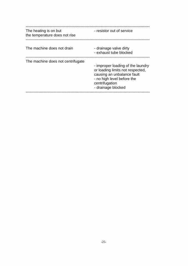
7. ANOMALIES DURING OPERATION AND START-UP Anomaly Check --------------------------------------------------------------------------------------------------- The cycle does not start - doors not closed correctly, - emergency stop activated,
- contact breaker, electricity outage
--------------------------------------------------------------------------------------------------- The control panel does not light up - fuses tripped - emergency stop activated, - processor off, - electricity outage --------------------------------------------------------------------------------------------------- The cycle starts but the drum does not turn - fuse of the regulator tripped
- press the yellow indicator light on the front side when it is on
--------------------------------------------------------------------------------------------------- The cycle starts but the water does not enter - water inlet closed, - pressure switch out of service, - electronic valve out of service - fuse tripped
- electronic valve of inlet out of service
--------------------------------------------------------------------------------------------------- The cycle starts but the water inflow does not stop - pressure switch out of service, - electronic valve dirty, - tub pressure switch clogged, - drainage valve still open --------------------------------------------------------------------------------------------------- The cycle starts but the heating does not engage - required water level not reached - fuse tripped
- contact coil heating out of service
- HS probe
-25-
--------------------------------------------------------------------------------------------------- The heating is on but - resistor out of service the temperature does not rise ---------------------------------------------------------------------------------------------------
The machine does not drain - drainage valve dirty - exhaust tube blocked --------------------------------------------------------------------------------------------------- The machine does not centrifugate
- improper loading of the laundry or loading limits not respected, causing an unbalance fault
- no high level before the centrifugation
- drainage blocked ---------------------------------------------------------------------------------------------------
-26-
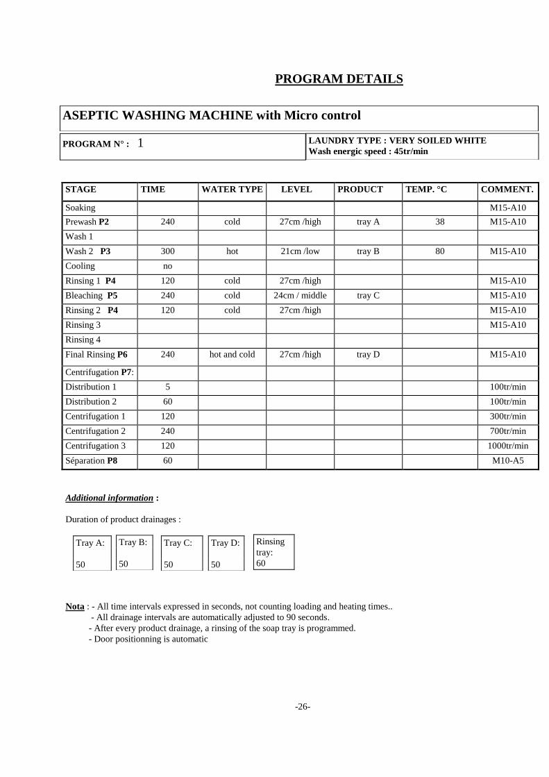
PROGRAM DETAILS
STAGE TIME WATER TYPE LEVEL PRODUCT TEMP. °C COMMENT.
Soaking M15-A10
Prewash P2 240 cold 27cm /high tray A 38 M15-A10
Wash 1
Wash 2 P3 300 hot 21cm /low tray B 80 M15-A10
Cooling no
Rinsing 1 P4 120 cold 27cm /high M15-A10
Bleaching P5 240 cold 24cm / middle tray C M15-A10
Rinsing 2 P4 120 cold 27cm /high M15-A10
Rinsing 3 M15-A10
Rinsing 4
Final Rinsing P6 240 hot and cold 27cm /high tray D M15-A10
Centrifugation P7:
Distribution 1 5 100tr/min
Distribution 2 60 100tr/min
Centrifugation 1 120 300tr/min
Centrifugation 2 240 700tr/min
Centrifugation 3 120 1000tr/min
Séparation P8 60 M10-A5
Additional information :
Duration of product drainages :
Nota : - All time intervals expressed in seconds, not counting loading and heating times..
- All drainage intervals are automatically adjusted to 90 seconds.
- After every product drainage, a rinsing of the soap tray is programmed.
- Door positionning is automatic
PROGRAM N° : 1 LAUNDRY TYPE : VERY SOILED WHITE
Wash energic speed : 45tr/min
ASEPTIC WASHING MACHINE with Micro control
Tray B:
50
Rinsing
tray:
60
Tray A:
50
Tray C:
50
Tray D:
50
-27-
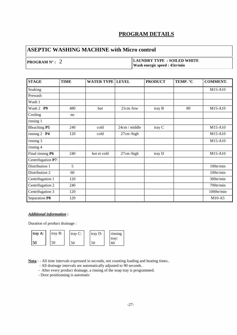
PROGRAM DETAILS
STAGE TIME WATER TYPE LEVEL PRODUCT TEMP. °C COMMENT.
Soaking M15-A10
Prewash
Wash 1
Wash 2 P9 480 hot 21cm /low tray B 80 M15-A10
Cooling no
rinsing 1
Bleaching P5 240 cold 24cm / middle tray C M15-A10
rinsing 2 P4 120 cold 27cm /high M15-A10
rinsing 3 M15-A10
rinsing 4
Final rinsing P6 240 hot et cold 27cm /high tray D M15-A10
Centrifugation P7:
Distribution 1 5 100tr/min
Distribution 2 60 100tr/min
Centrifugation 1 120 300tr/min
Centrifugation 2 240 700tr/min
Centrifugation 3 120 1000tr/min
Separation P8 120 M10-A5
Additional information :
Duration of product drainage :
Nota : - All time intervals expressed in seconds, not counting loading and heating times..
- All drainage intervals are automatically adjusted to 90 seconds.
- After every product drainage, a rinsing of the soap tray is programmed.
- Door positionning is automatic
PROGRAM N° : 2 LAUNDRY TYPE : SOILED WHITE
Wash energic speed : 45tr/min
ASEPTIC WASHING MACHINE with Micro control
tray B:
50
tray A:
50
rinsing
tray:
60
tray C:
50
tray A:
50
tray D:
50

-28-
PROGRAM DETAILS
STAGE TIME WATER TYPE LEVEL PRODUCT TEMP. °C COMMENT.
Soaking M15-A10
Prewash P10 180 Cold 27cm / high Tray A 30 M15-A10
Wash 1
Wash 2 P11 300 Hot et cold 21cm /low tray B 60 M15-A10
Cooling no
rinsing 1
Bleaching
rinsing 2 P4 120 Cold 27cm /high M15-A10
rinsing 3 P4 120 Cold 27cm /high M15-A10
rinsing 4
Final rinsinglP16 240 Cold 27cm /high tray D M15-A10
Centrifugation P12:
Distribution 1 5 100tr/min
Distribution 2 60 100tr/min
Centrifugation 1 120 300tr/min
Centrifugation 2 300 700tr/min
Centrifugation 3 120 1000tr/min
Separation P8 60 M10-A5
Additional information :
Duration of product drainage :
Nota : - All time intervals expressed in seconds, not counting loading and heating times..
- All drainage intervals are automatically adjusted to 90 seconds.
- After every product drainage, a rinsing of the soap tray is programmed.
- Door positionning is automatic
PROGRAM N° : 3 LAUNDRY TYPE : COLOUR
Wash energic speed : 45tr/min
ASEPTIC WASHING MACHINE with Micro control
tray B:
50
tray A:
50
rinsing
tray:
60
tray C:
50
tray A:
50
tray D:
50
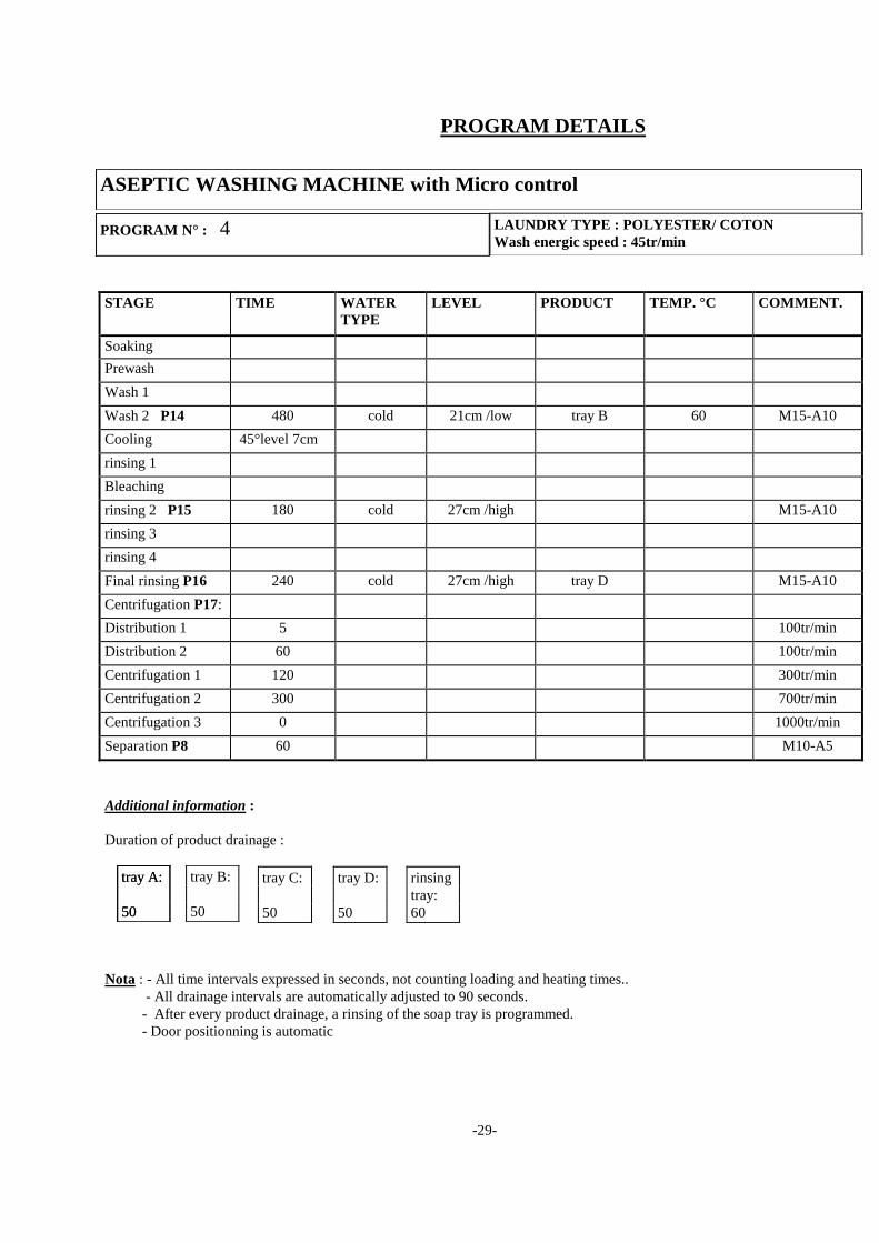
-29-
PROGRAM DETAILS
STAGE TIME WATER
TYPE
LEVEL PRODUCT TEMP. °C COMMENT.
Soaking
Prewash
Wash 1
Wash 2 P14 480 cold 21cm /low tray B 60 M15-A10
Cooling 45°level 7cm
rinsing 1
Bleaching
rinsing 2 P15 180 cold 27cm /high M15-A10
rinsing 3
rinsing 4
Final rinsing P16 240 cold 27cm /high tray D M15-A10
Centrifugation P17:
Distribution 1 5 100tr/min
Distribution 2 60 100tr/min
Centrifugation 1 120 300tr/min
Centrifugation 2 300 700tr/min
Centrifugation 3 0 1000tr/min
Separation P8 60 M10-A5
Additional information :
Duration of product drainage :
Nota : - All time intervals expressed in seconds, not counting loading and heating times..
- All drainage intervals are automatically adjusted to 90 seconds.
- After every product drainage, a rinsing of the soap tray is programmed.
- Door positionning is automatic
PROGRAM N° : 4 LAUNDRY TYPE : POLYESTER/ COTON
Wash energic speed : 45tr/min
ASEPTIC WASHING MACHINE with Micro control
tray B:
50
tray A:
50
rinsing
tray:
60
tray C:
50
tray A:
50
tray D:
50
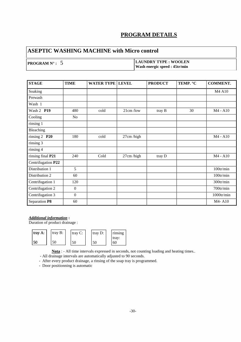
-30-
PROGRAM DETAILS
STAGE TIME WATER TYPE LEVEL PRODUCT TEMP. °C COMMENT.
Soaking M4 A10
Prewash
Wash 1
Wash 2 P19 480 cold 21cm /low tray B 30 M4 - A10
Cooling No
rinsing 1
Bleaching
rinsing 2 P20 180 cold 27cm /high M4 - A10
rinsing 3
rinsing 4
rinsing final P21 240 Cold 27cm /high tray D M4 - A10
Centrifugation P22
:
Distribution 1 5 100tr/min
Distribution 2 60 100tr/min
Centrifugation 1 120 300tr/min
Centrifugation 2 0 700tr/min
Centrifugation 3 0 1000tr/min
Separation P8 60 M4- A10
Additional information :
Duration of product drainage :
Nota : - All time intervals expressed in seconds, not counting loading and heating times..
- All drainage intervals are automatically adjusted to 90 seconds.
- After every product drainage, a rinsing of the soap tray is programmed.
- Door positionning is automatic
PROGRAM N° : 5 LAUNDRY TYPE : WOOLEN
Wash energic speed : 45tr/min
ASEPTIC WASHING MACHINE with Micro control
tray B:
50
tray A:
50
rinsing
tray:
60
tray C:
50
tray A:
50
tray D:
50
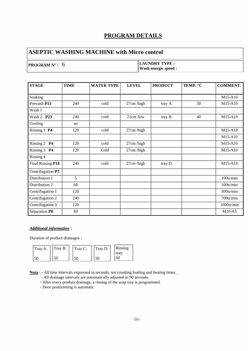
-31-
PROGRAM DETAILS
STAGE TIME WATER TYPE LEVEL PRODUCT TEMP. °C COMMENT.
Soaking M15-A10
Prewash P13 240 cold 27cm /high tray A 30 M15-A10
Wash 1
Wash 2 P23 240 cold 21cm /low tray B 40 M15-A10
Cooling no
Rinsing 1 P4 120 cold 27cm /high M15-A10
M15-A10
Rinsing 2 P4 120 cold 27cm /high M15-A10
Rinsing 3 P4 120 Cold 27cm /high M15-A10
Rinsing 4
Final Rinsing P16 240 cold 27cm /high tray D M15-A10
Centrifugation P7:
Distribution 1 5 100tr/min
Distribution 2 60 100tr/min
Centrifugation 1 120 300tr/min
Centrifugation 2 240 700tr/min
Centrifugation 3 120 1000tr/min
Séparation P8 60 M10-A5
Additional information :
Duration of product drainages :
Nota : - All time intervals expressed in seconds, not counting loading and heating times..
- All drainage intervals are automatically adjusted to 90 seconds.
- After every product drainage, a rinsing of the soap tray is programmed.
- Door positionning is automatic
PROGRAM N° : 6 LAUNDRY TYPE :
Wash energic speed :
ASEPTIC WASHING MACHINE with Micro control
Tray B:
50
Rinsing
tray:
60
Tray A:
50
Tray C:
50
Tray D:
50
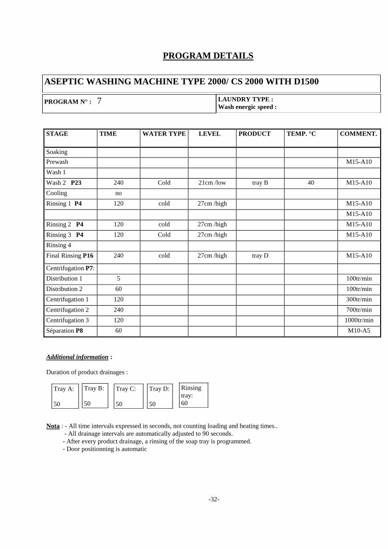
-32-
PROGRAM DETAILS
STAGE TIME WATER TYPE LEVEL PRODUCT TEMP. °C COMMENT.
Soaking
Prewash M15-A10
Wash 1
Wash 2 P23 240 Cold 21cm /low tray B 40 M15-A10
Cooling no
Rinsing 1 P4 120 cold 27cm /high M15-A10
M15-A10
Rinsing 2 P4 120 cold 27cm /high M15-A10
Rinsing 3 P4 120 Cold 27cm /high M15-A10
Rinsing 4
Final Rinsing P16 240 cold 27cm /high tray D M15-A10
Centrifugation P7:
Distribution 1 5 100tr/min
Distribution 2 60 100tr/min
Centrifugation 1 120 300tr/min
Centrifugation 2 240 700tr/min
Centrifugation 3 120 1000tr/min
Séparation P8 60 M10-A5
Additional information :
Duration of product drainages :
Nota : - All time intervals expressed in seconds, not counting loading and heating times..
- All drainage intervals are automatically adjusted to 90 seconds.
- After every product drainage, a rinsing of the soap tray is programmed.
- Door positionning is automatic
PROGRAM N° : 7 LAUNDRY TYPE :
Wash energic speed :
ASEPTIC WASHING MACHINE TYPE 2000/ CS 2000 WITH D1500
Tray B:
50
Rinsing
tray:
60
Tray A:
50
Tray C:
50
Tray D:
50
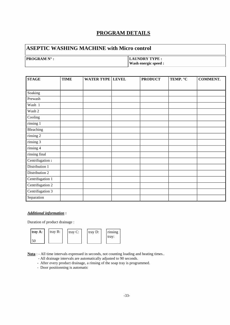
-33-
PROGRAM DETAILS
STAGE TIME WATER TYPE LEVEL PRODUCT TEMP. °C COMMENT.
Soaking
Prewash
Wash 1
Wash 2
Cooling
rinsing 1
Bleaching
rinsing 2
rinsing 3
rinsing 4
rinsing final
Centrifugation :
Distribution 1
Distribution 2
Centrifugation 1
Centrifugation 2
Centrifugation 3
Separation
Additional information :
Duration of product drainage :
Nota : - All time intervals expressed in seconds, not counting loading and heating times..
- All drainage intervals are automatically adjusted to 90 seconds.
- After every product drainage, a rinsing of the soap tray is programmed.
- Door positionning is automatic
PROGRAM N° : LAUNDRY TYPE :
Wash energic speed :
ASEPTIC WASHING MACHINE with Micro control
tray B:
tray A:
50
rinsing
tray:
tray C:
tray A:
tray D:
-34-
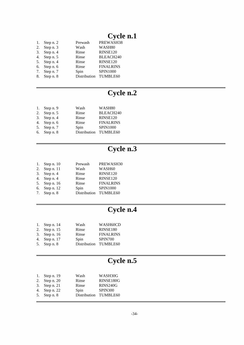
Cycle n.1 1. Step n. 2 Prewash PREWASH38
2. Step n. 3 Wash WASH80
3. Step n. 4 Rinse RINSE120
4. Step n. 5 Rinse BLEACH240
5. Step n. 4 Rinse RINSE120
6. Step n. 6 Rinse FINALRINS
7. Step n. 7 Spin SPIN1000
8. Step n. 8 Distribution TUMBLE60
Cycle n.2
1. Step n. 9 Wash WASH80
2. Step n. 5 Rinse BLEACH240
3. Step n. 4 Rinse RINSE120
4. Step n. 6 Rinse FINALRINS
5. Step n. 7 Spin SPIN1000
6. Step n. 8 Distribution TUMBLE60
Cycle n.3
1. Step n. 10 Prewash PREWASH30
2. Step n. 11 Wash WASH60
3. Step n. 4 Rinse RINSE120
4. Step n. 4 Rinse RINSE120
5. Step n. 16 Rinse FINALRINS
6. Step n. 12 Spin SPIN1000
7. Step n. 8 Distribution TUMBLE60
Cycle n.4
1. Step n. 14 Wash WASH60CD
2. Step n. 15 Rinse RINSE180
3. Step n. 16 Rinse FINALRINS
4. Step n. 17 Spin SPIN700
5. Step n. 8 Distribution TUMBLE60
Cycle n.5
1. Step n. 19 Wash WASH30G
2. Step n. 20 Rinse RINSE180G
3. Step n. 21 Rinse RINS240G
4. Step n. 22 Spin SPIN300
5. Step n. 8 Distribution TUMBLE60
-35-
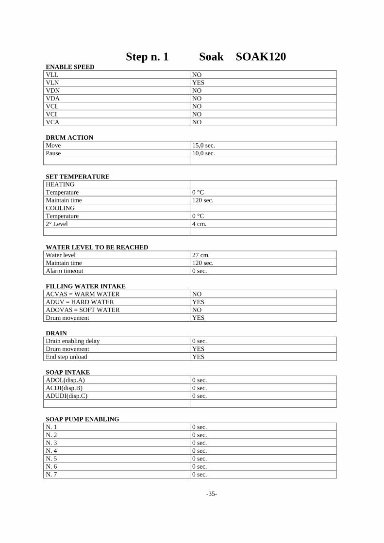
Step n. 1 Soak SOAK120 ENABLE SPEED
VLL NO
VLN YES
VDN NO
VDA NO
VCL NO
VCI NO
VCA NO
DRUM ACTION
Move 15,0 sec.
Pause 10,0 sec.
SET TEMPERATURE
HEATING
Temperature 0 °C
Maintain time 120 sec.
COOLING
Temperature 0 °C
2° Level 4 cm.
WATER LEVEL TO BE REACHED
Water level 27 cm.
Maintain time 120 sec.
Alarm timeout 0 sec.
FILLING WATER INTAKE
ACVAS = WARM WATER NO
ADUV = HARD WATER YES
ADOVAS = SOFT WATER NO
Drum movement YES
DRAIN
Drain enabling delay 0 sec.
Drum movement YES
End step unload YES
SOAP INTAKE
ADOL(disp.A) 0 sec.
ACDI(disp.B) 0 sec.
ADUDI(disp.C) 0 sec.
SOAP PUMP ENABLING
N. 1 0 sec.
N. 2 0 sec.
N. 3 0 sec.
N. 4 0 sec.
N. 5 0 sec.
N. 6 0 sec.
N. 7 0 sec.
-36-
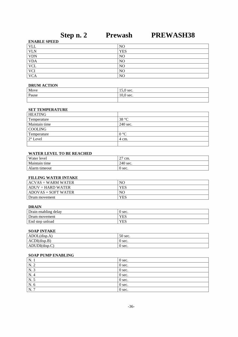
Step n. 2 Prewash PREWASH38 ENABLE SPEED
VLL NO
VLN YES
VDN NO
VDA NO
VCL NO
VCI NO
VCA NO
DRUM ACTION
Move 15,0 sec.
Pause 10,0 sec.
SET TEMPERATURE
HEATING
Temperature 38 °C
Maintain time 240 sec.
COOLING
Temperature 0 °C
2° Level 4 cm.
WATER LEVEL TO BE REACHED
Water level 27 cm.
Maintain time 240 sec.
Alarm timeout 0 sec.
FILLING WATER INTAKE
ACVAS = WARM WATER NO
ADUV = HARD WATER YES
ADOVAS = SOFT WATER NO
Drum movement YES
DRAIN
Drain enabling delay 0 sec.
Drum movement YES
End step unload YES
SOAP INTAKE
ADOL(disp.A) 50 sec.
ACDI(disp.B) 0 sec.
ADUDI(disp.C) 0 sec.
SOAP PUMP ENABLING
N. 1 0 sec.
N. 2 0 sec.
N. 3 0 sec.
N. 4 0 sec.
N. 5 0 sec.
N. 6 0 sec.
N. 7 0 sec.

-37-
Step n. 3 Wash WASH80 ENABLE SPEED
VLL NO
VLN YES
VDN NO
VDA NO
VCL NO
VCI NO
VCA NO
DRUM ACTION
Move 15,0 sec.
Pause 10,0 sec.
SET TEMPERATURE
HEATING
Temperature 80 °C
Maintain time 300 sec.
COOLING
Temperature 0 °C
2° Level 4 cm.
WATER LEVEL TO BE REACHED
Water level 21 cm.
Maintain time 300 sec.
Alarm timeout 0 sec.
FILLING WATER INTAKE
ACVAS = WARM WATER YES
ADUV = HARD WATER NO
ADOVAS = SOFT WATER NO
Drum movement YES
DRAIN
Drain enabling delay 0 sec.
Drum movement YES
End step unload YES
SOAP INTAKE
ADOL(disp.A) 0 sec.
ACDI(disp.B) 50 sec.
ADUDI(disp.C) 0 sec.
SOAP PUMP ENABLING
N. 1 0 sec.
N. 2 0 sec.
N. 3 0 sec.
N. 4 0 sec.
N. 5 0 sec.
N. 6 0 sec.
N. 7 0 sec.

-38-
Step n. 4 Rinse RINSE120 ENABLE SPEED
VLL NO
VLN YES
VDN NO
VDA NO
VCL NO
VCI NO
VCA NO
DRUM ACTION
Move 15,0 sec.
Pause 10,0 sec.
SET TEMPERATURE
HEATING
Temperature 0 °C
Maintain time 120 sec.
COOLING
Temperature 0 °C
2° Level 4 cm.
WATER LEVEL TO BE REACHED
Water level 27 cm.
Maintain time 120 sec.
Alarm timeout 0 sec.
FILLING WATER INTAKE
ACVAS = WARM WATER NO
ADUV = HARD WATER YES
ADOVAS = SOFT WATER NO
Drum movement YES
DRAIN
Drain enabling delay 0 sec.
Drum movement YES
End step unload YES
SOAP INTAKE
ADOL(disp.A) 0 sec.
ACDI(disp.B) 0 sec.
ADUDI(disp.C) 0 sec.
SOAP PUMP ENABLING
N. 1 0 sec.
N. 2 0 sec.
N. 3 0 sec.
N. 4 0 sec.
N. 5 0 sec.
N. 6 0 sec.
N. 7 0 sec.

-39-
Step n. 5 Rinse BLEACH240 ENABLE SPEED
VLL NO
VLN YES
VDN NO
VDA NO
VCL NO
VCI NO
VCA NO
DRUM ACTION
Move 15,0 sec.
Pause 10,0 sec.
SET TEMPERATURE
HEATING
Temperature 0 °C
Maintain time 240 sec.
COOLING
Temperature 0 °C
2° Level 4 cm.
WATER LEVEL TO BE REACHED
Water level 24 cm.
Maintain time 240 sec.
Alarm timeout 0 sec.
FILLING WATER INTAKE
ACVAS = WARM WATER NO
ADUV = HARD WATER YES
ADOVAS = SOFT WATER NO
Drum movement YES
DRAIN
Drain enabling delay 0 sec.
Drum movement YES
End step unload YES
SOAP INTAKE
ADOL(disp.A) 0 sec.
ACDI(disp.B) 0 sec.
ADUDI(disp.C) 50 sec.
SOAP PUMP ENABLING
N. 1 0 sec.
N. 2 0 sec.
N. 3 0 sec.
N. 4 0 sec.
N. 5 0 sec.
N. 6 0 sec.
N. 7 0 sec.

-40-
Step n. 6 Rinse FINALRINS ENABLE SPEED
VLL NO
VLN YES
VDN NO
VDA NO
VCL NO
VCI NO
VCA NO
DRUM ACTION
Move 15,0 sec.
Pause 10,0 sec.
SET TEMPERATURE
HEATING
Temperature 0 °C
Maintain time 240 sec.
COOLING
Temperature 0 °C
2° Level 4 cm.
WATER LEVEL TO BE REACHED
Water level 27 cm.
Maintain time 240 sec.
Alarm timeout 0 sec.
FILLING WATER INTAKE
ACVAS = WARM WATER YES
ADUV = HARD WATER YES
ADOVAS = SOFT WATER NO
Drum movement YES
DRAIN
Drain enabling delay 0 sec.
Drum movement YES
End step unload NO
SOAP INTAKE
ADOL(disp.A) 0 sec.
ACDI(disp.B) 0 sec.
ADUDI(disp.C) 0 sec.
SOAP PUMP ENABLING
N. 1 0 sec.
N. 2 0 sec.
N. 3 0 sec.
N. 4 0 sec.
N. 5 0 sec.
N. 6 0 sec.
N. 7 0 sec.
-41-
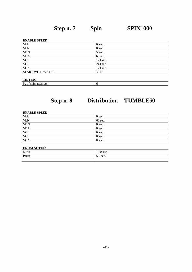
Step n. 7 Spin SPIN1000
ENABLE SPEED
VLL 0 sec.
VLN 0 sec.
VDN 5 sec.
VDA 60 sec.
VCL 120 sec.
VCI 240 sec.
VCA 120 sec.
START WITH WATER YES
TILTING
N. of spin attempts 6
Step n. 8 Distribution TUMBLE60
ENABLE SPEED
VLL 0 sec.
VLN 60 sec.
VDN 0 sec.
VDA 0 sec.
VCL 0 sec.
VCI 0 sec.
VCA 0 sec.
DRUM ACTION
Move 10,0 sec.
Pause 5,0 sec.

-42-
Step n. 9 Wash WASH80 ENABLE SPEED
VLL NO
VLN YES
VDN NO
VDA NO
VCL NO
VCI NO
VCA NO
DRUM ACTION
Move 15,0 sec.
Pause 10,0 sec.
SET TEMPERATURE
HEATING
Temperature 80 °C
Maintain time 480 sec.
COOLING
Temperature 0 °C
2° Level 4 cm.
WATER LEVEL TO BE REACHED
Water level 21 cm.
Maintain time 480 sec.
Alarm timeout 0 sec.
FILLING WATER INTAKE
ACVAS = WARM WATER YES
ADUV = HARD WATER NO
ADOVAS = SOFT WATER NO
Drum movement YES
DRAIN
Drain enabling delay 0 sec.
Drum movement YES
End step unload YES
SOAP INTAKE
ADOL(disp.A) 0 sec.
ACDI(disp.B) 50 sec.
ADUDI(disp.C) 0 sec.
SOAP PUMP ENABLING
N. 1 0 sec.
N. 2 0 sec.
N. 3 0 sec.
N. 4 0 sec.
N. 5 0 sec.
N. 6 0 sec.
N. 7 0 sec.
-43-
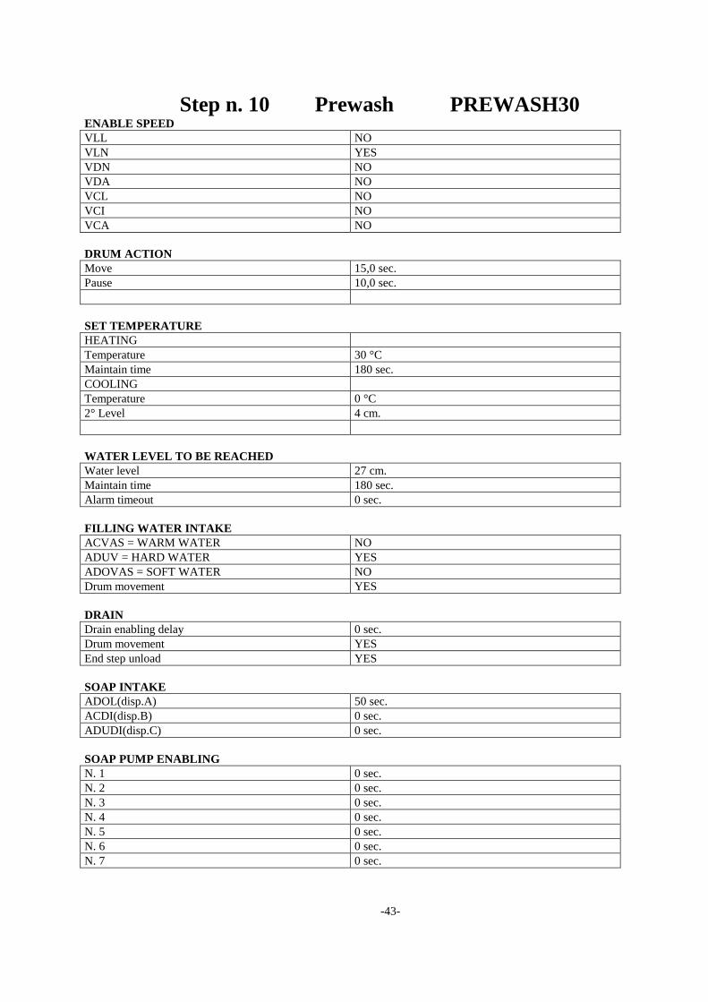
Step n. 10 Prewash PREWASH30 ENABLE SPEED
VLL NO
VLN YES
VDN NO
VDA NO
VCL NO
VCI NO
VCA NO
DRUM ACTION
Move 15,0 sec.
Pause 10,0 sec.
SET TEMPERATURE
HEATING
Temperature 30 °C
Maintain time 180 sec.
COOLING
Temperature 0 °C
2° Level 4 cm.
WATER LEVEL TO BE REACHED
Water level 27 cm.
Maintain time 180 sec.
Alarm timeout 0 sec.
FILLING WATER INTAKE
ACVAS = WARM WATER NO
ADUV = HARD WATER YES
ADOVAS = SOFT WATER NO
Drum movement YES
DRAIN
Drain enabling delay 0 sec.
Drum movement YES
End step unload YES
SOAP INTAKE
ADOL(disp.A) 50 sec.
ACDI(disp.B) 0 sec.
ADUDI(disp.C) 0 sec.
SOAP PUMP ENABLING
N. 1 0 sec.
N. 2 0 sec.
N. 3 0 sec.
N. 4 0 sec.
N. 5 0 sec.
N. 6 0 sec.
N. 7 0 sec.

-44-
Step n. 11 Wash WASH60 ENABLE SPEED
VLL NO
VLN YES
VDN NO
VDA NO
VCL NO
VCI NO
VCA NO
DRUM ACTION
Move 15,0 sec.
Pause 10,0 sec.
SET TEMPERATURE
HEATING
Temperature 60 °C
Maintain time 300 sec.
COOLING
Temperature 0 °C
2° Level 4 cm.
WATER LEVEL TO BE REACHED
Water level 21 cm.
Maintain time 300 sec.
Alarm timeout 0 sec.
FILLING WATER INTAKE
ACVAS = WARM WATER YES
ADUV = HARD WATER YES
ADOVAS = SOFT WATER NO
Drum movement YES
DRAIN
Drain enabling delay 0 sec.
Drum movement YES
End step unload YES
SOAP INTAKE
ADOL(disp.A) 0 sec.
ACDI(disp.B) 50 sec.
ADUDI(disp.C) 0 sec.
SOAP PUMP ENABLING
N. 1 0 sec.
N. 2 0 sec.
N. 3 0 sec.
N. 4 0 sec.
N. 5 0 sec.
N. 6 0 sec.
N. 7 0 sec.
-45-
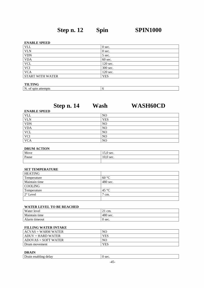
Step n. 12 Spin SPIN1000
ENABLE SPEED
VLL 0 sec.
VLN 0 sec.
VDN 5 sec.
VDA 60 sec.
VCL 120 sec.
VCI 300 sec.
VCA 120 sec.
START WITH WATER YES
TILTING
N. of spin attempts 6
Step n. 14 Wash WASH60CD ENABLE SPEED
VLL NO
VLN YES
VDN NO
VDA NO
VCL NO
VCI NO
VCA NO
DRUM ACTION
Move 15,0 sec.
Pause 10,0 sec.
SET TEMPERATURE
HEATING
Temperature 60 °C
Maintain time 480 sec.
COOLING
Temperature 45 °C
2° Level 7 cm.
WATER LEVEL TO BE REACHED
Water level 21 cm.
Maintain time 480 sec.
Alarm timeout 0 sec.
FILLING WATER INTAKE
ACVAS = WARM WATER NO
ADUV = HARD WATER YES
ADOVAS = SOFT WATER NO
Drum movement YES
DRAIN
Drain enabling delay 0 sec.
-46-
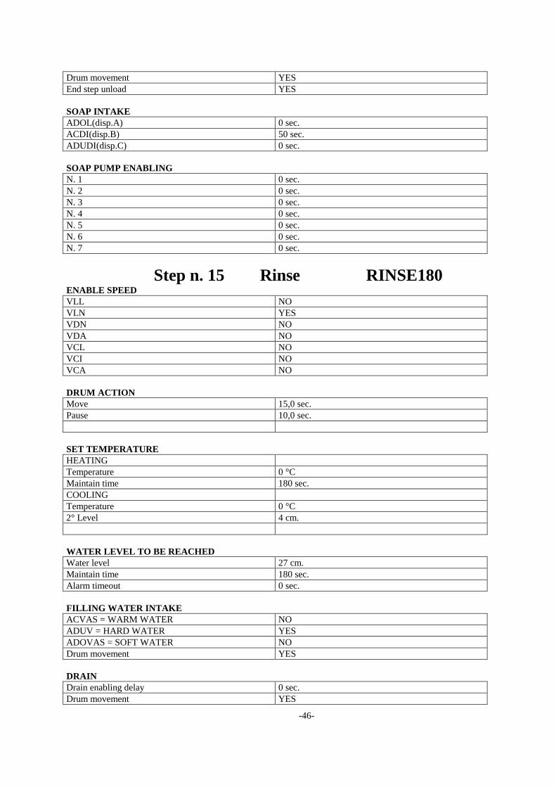
Drum movement YES
End step unload YES
SOAP INTAKE
ADOL(disp.A) 0 sec.
ACDI(disp.B) 50 sec.
ADUDI(disp.C) 0 sec.
SOAP PUMP ENABLING
N. 1 0 sec.
N. 2 0 sec.
N. 3 0 sec.
N. 4 0 sec.
N. 5 0 sec.
N. 6 0 sec.
N. 7 0 sec.
Step n. 15 Rinse RINSE180 ENABLE SPEED
VLL NO
VLN YES
VDN NO
VDA NO
VCL NO
VCI NO
VCA NO
DRUM ACTION
Move 15,0 sec.
Pause 10,0 sec.
SET TEMPERATURE
HEATING
Temperature 0 °C
Maintain time 180 sec.
COOLING
Temperature 0 °C
2° Level 4 cm.
WATER LEVEL TO BE REACHED
Water level 27 cm.
Maintain time 180 sec.
Alarm timeout 0 sec.
FILLING WATER INTAKE
ACVAS = WARM WATER NO
ADUV = HARD WATER YES
ADOVAS = SOFT WATER NO
Drum movement YES
DRAIN
Drain enabling delay 0 sec.
Drum movement YES
-47-
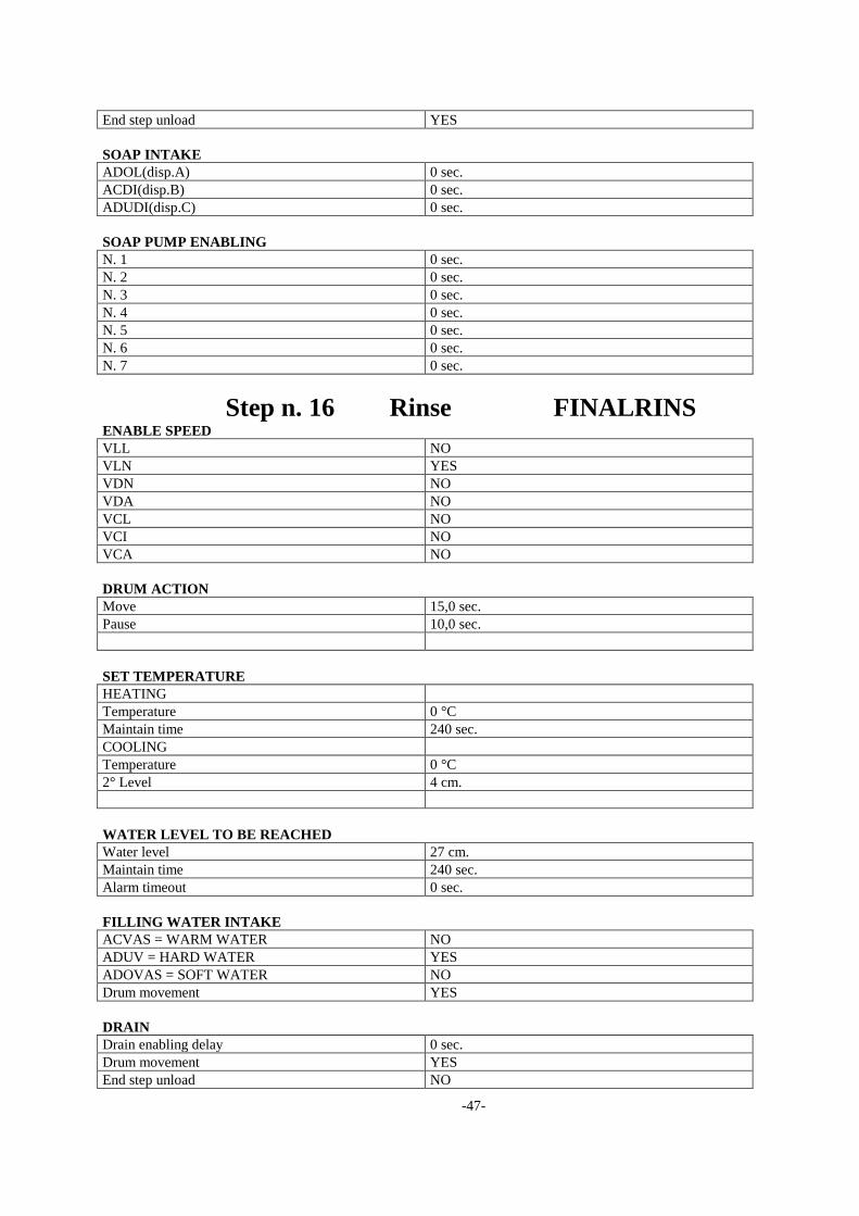
End step unload YES
SOAP INTAKE
ADOL(disp.A) 0 sec.
ACDI(disp.B) 0 sec.
ADUDI(disp.C) 0 sec.
SOAP PUMP ENABLING
N. 1 0 sec.
N. 2 0 sec.
N. 3 0 sec.
N. 4 0 sec.
N. 5 0 sec.
N. 6 0 sec.
N. 7 0 sec.
Step n. 16 Rinse FINALRINS ENABLE SPEED
VLL NO
VLN YES
VDN NO
VDA NO
VCL NO
VCI NO
VCA NO
DRUM ACTION
Move 15,0 sec.
Pause 10,0 sec.
SET TEMPERATURE
HEATING
Temperature 0 °C
Maintain time 240 sec.
COOLING
Temperature 0 °C
2° Level 4 cm.
WATER LEVEL TO BE REACHED
Water level 27 cm.
Maintain time 240 sec.
Alarm timeout 0 sec.
FILLING WATER INTAKE
ACVAS = WARM WATER NO
ADUV = HARD WATER YES
ADOVAS = SOFT WATER NO
Drum movement YES
DRAIN
Drain enabling delay 0 sec.
Drum movement YES
End step unload NO
-48-
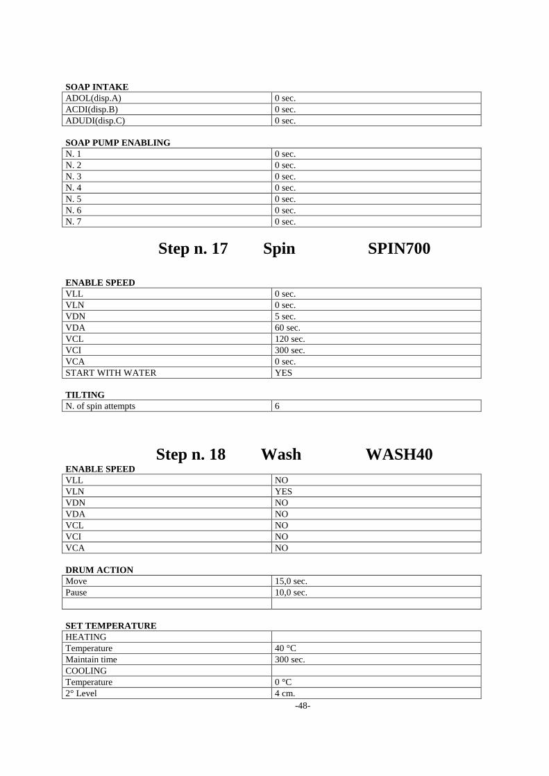
SOAP INTAKE
ADOL(disp.A) 0 sec.
ACDI(disp.B) 0 sec.
ADUDI(disp.C) 0 sec.
SOAP PUMP ENABLING
N. 1 0 sec.
N. 2 0 sec.
N. 3 0 sec.
N. 4 0 sec.
N. 5 0 sec.
N. 6 0 sec.
N. 7 0 sec.
Step n. 17 Spin SPIN700
ENABLE SPEED
VLL 0 sec.
VLN 0 sec.
VDN 5 sec.
VDA 60 sec.
VCL 120 sec.
VCI 300 sec.
VCA 0 sec.
START WITH WATER YES
TILTING
N. of spin attempts 6
Step n. 18 Wash WASH40 ENABLE SPEED
VLL NO
VLN YES
VDN NO
VDA NO
VCL NO
VCI NO
VCA NO
DRUM ACTION
Move 15,0 sec.
Pause 10,0 sec.
SET TEMPERATURE
HEATING
Temperature 40 °C
Maintain time 300 sec.
COOLING
Temperature 0 °C
2° Level 4 cm.
-49-
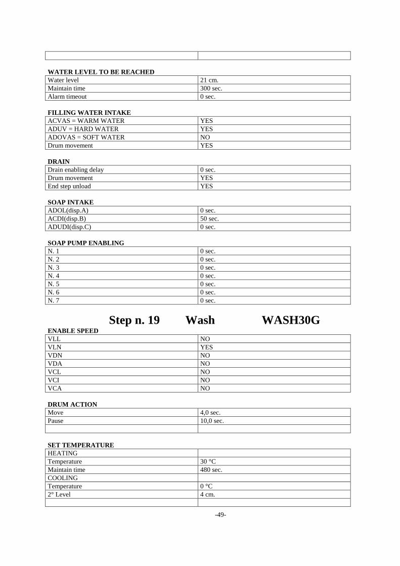
WATER LEVEL TO BE REACHED
Water level 21 cm.
Maintain time 300 sec.
Alarm timeout 0 sec.
FILLING WATER INTAKE
ACVAS = WARM WATER YES
ADUV = HARD WATER YES
ADOVAS = SOFT WATER NO
Drum movement YES
DRAIN
Drain enabling delay 0 sec.
Drum movement YES
End step unload YES
SOAP INTAKE
ADOL(disp.A) 0 sec.
ACDI(disp.B) 50 sec.
ADUDI(disp.C) 0 sec.
SOAP PUMP ENABLING
N. 1 0 sec.
N. 2 0 sec.
N. 3 0 sec.
N. 4 0 sec.
N. 5 0 sec.
N. 6 0 sec.
N. 7 0 sec.
Step n. 19 Wash WASH30G ENABLE SPEED
VLL NO
VLN YES
VDN NO
VDA NO
VCL NO
VCI NO
VCA NO
DRUM ACTION
Move 4,0 sec.
Pause 10,0 sec.
SET TEMPERATURE
HEATING
Temperature 30 °C
Maintain time 480 sec.
COOLING
Temperature 0 °C
2° Level 4 cm.
-50-
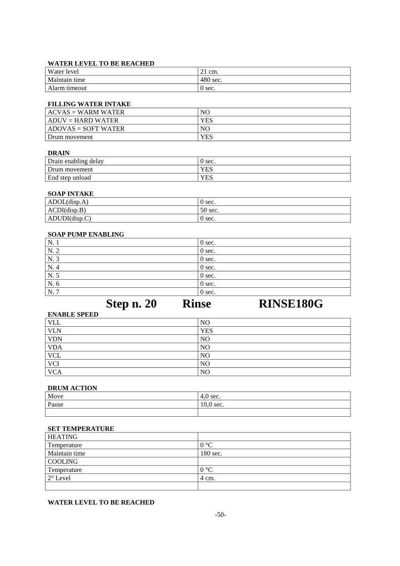
WATER LEVEL TO BE REACHED
Water level 21 cm.
Maintain time 480 sec.
Alarm timeout 0 sec.
FILLING WATER INTAKE
ACVAS = WARM WATER NO
ADUV = HARD WATER YES
ADOVAS = SOFT WATER NO
Drum movement YES
DRAIN
Drain enabling delay 0 sec.
Drum movement YES
End step unload YES
SOAP INTAKE
ADOL(disp.A) 0 sec.
ACDI(disp.B) 50 sec.
ADUDI(disp.C) 0 sec.
SOAP PUMP ENABLING
N. 1 0 sec.
N. 2 0 sec.
N. 3 0 sec.
N. 4 0 sec.
N. 5 0 sec.
N. 6 0 sec.
N. 7 0 sec.
Step n. 20 Rinse RINSE180G ENABLE SPEED
VLL NO
VLN YES
VDN NO
VDA NO
VCL NO
VCI NO
VCA NO
DRUM ACTION
Move 4,0 sec.
Pause 10,0 sec.
SET TEMPERATURE
HEATING
Temperature 0 °C
Maintain time 180 sec.
COOLING
Temperature 0 °C
2° Level 4 cm.
WATER LEVEL TO BE REACHED
-51-
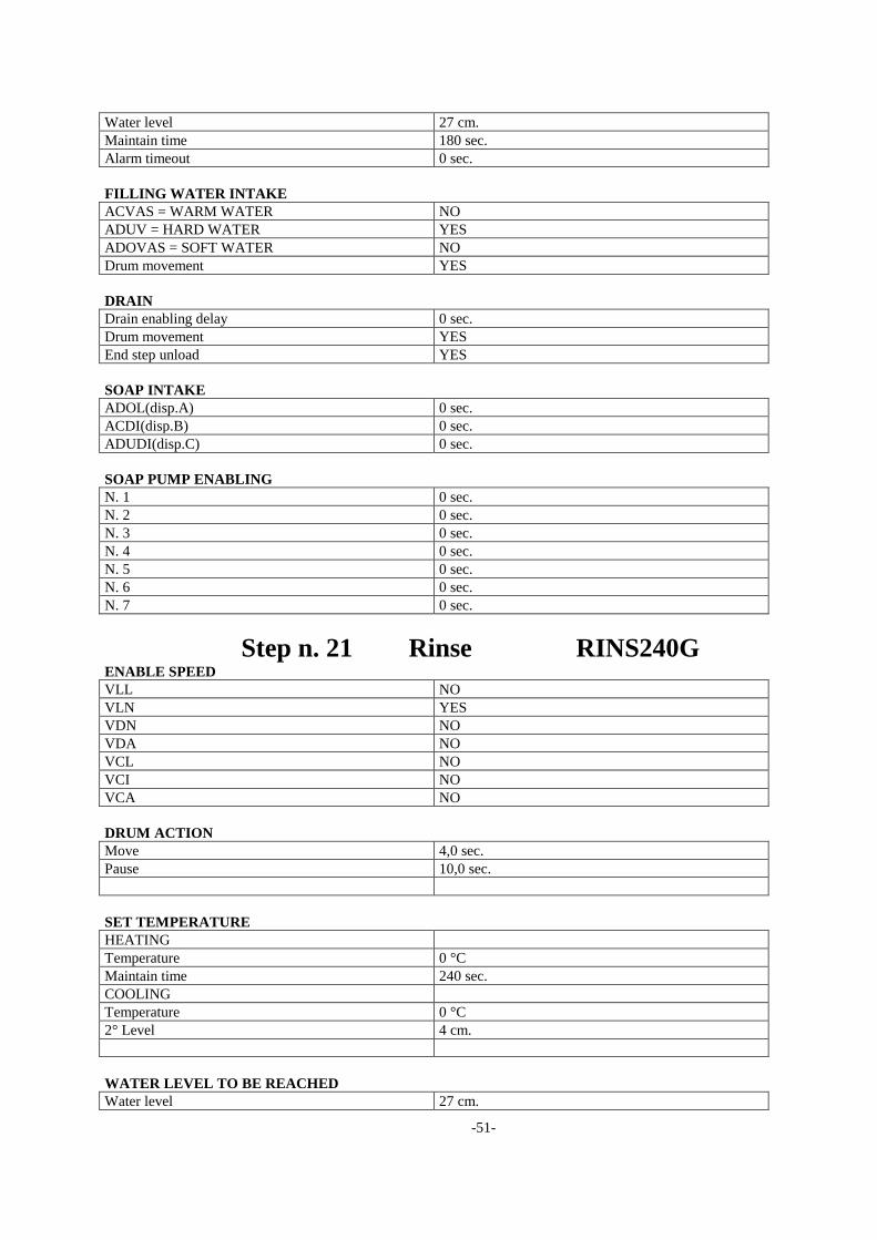
Water level 27 cm.
Maintain time 180 sec.
Alarm timeout 0 sec.
FILLING WATER INTAKE
ACVAS = WARM WATER NO
ADUV = HARD WATER YES
ADOVAS = SOFT WATER NO
Drum movement YES
DRAIN
Drain enabling delay 0 sec.
Drum movement YES
End step unload YES
SOAP INTAKE
ADOL(disp.A) 0 sec.
ACDI(disp.B) 0 sec.
ADUDI(disp.C) 0 sec.
SOAP PUMP ENABLING
N. 1 0 sec.
N. 2 0 sec.
N. 3 0 sec.
N. 4 0 sec.
N. 5 0 sec.
N. 6 0 sec.
N. 7 0 sec.
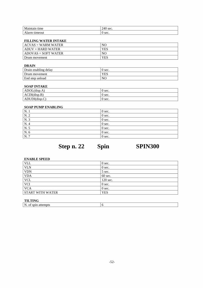
Step n. 21 Rinse RINS240G ENABLE SPEED
VLL NO
VLN YES
VDN NO
VDA NO
VCL NO
VCI NO
VCA NO
DRUM ACTION
Move 4,0 sec.
Pause 10,0 sec.
SET TEMPERATURE
HEATING
Temperature 0 °C
Maintain time 240 sec.
COOLING
Temperature 0 °C
2° Level 4 cm.
WATER LEVEL TO BE REACHED
Water level 27 cm.
-52-
Maintain time 240 sec.
Alarm timeout 0 sec.
FILLING WATER INTAKE
ACVAS = WARM WATER NO
ADUV = HARD WATER YES
ADOVAS = SOFT WATER NO
Drum movement YES
DRAIN
Drain enabling delay 0 sec.
Drum movement YES
End step unload NO
SOAP INTAKE
ADOL(disp.A) 0 sec.
ACDI(disp.B) 0 sec.
ADUDI(disp.C) 0 sec.
SOAP PUMP ENABLING
N. 1 0 sec.
N. 2 0 sec.
N. 3 0 sec.
N. 4 0 sec.
N. 5 0 sec.
N. 6 0 sec.
N. 7 0 sec.
Step n. 22 Spin SPIN300
ENABLE SPEED
VLL 0 sec.
VLN 0 sec.
VDN 5 sec.
VDA 60 sec.
VCL 120 sec.
VCI 0 sec.
VCA 0 sec.
START WITH WATER YES
TILTING
N. of spin attempts 6