Embed Size (px)
Citation preview
Hydraulic Breaker
Vulcan V30GS
Operation
&
Maintenance Manual
- 1 -
CONTENTS 1. Specifications
1.1 General specifications for V30GS
1.2 Tool specifications
1.3 Structure
2. Operation 2.1 Product numbers
2.2 Tool Selection
2.3 Breaking Principles
2.4 Correct working methods
2.5 Operating temperature
2.6 Other important points
2.7 Storage
2.8 Mounting and Dismounting the Hammer
2.9 Operating Pressure Settings
2.10 Hose and Pipe Specification
2.11 Hydraulic Circuit
3. Lubrication 3.1 Manual Lubrication
3.2 Hydraulic Oil
4. Maintenance 4.1 Delivery Precautions
4.2 Inspection of the nitrogen gas charging in the back head
4.3 Inspection of nitrogen gas in the accumulator
4.4 Side Rod Inspection and Replacement
4.5 Adjusting Control Methods
4.6 Regulating oil flow rate of valve adjuster
4.7 Wearing parts
4.8 Wear limit of tool and tool bushing
- 2 -
CONTENTS
5. Disassembling and Assembling 5.1 Disassembling
5.2 Assembling
5.3 Torques
5.4 Workshop tool list
6. Troubleshooting Guide 6.1 Oil leakage
6.2 No impact
6.3 Irregular blows after normal beginning
6.4 Lack of blowing
7. General and Safety Information 7.1 General
7.2 Safety
8. Parts 8.1 V30GS Housing (Box)
8.2 V30G Hammer Assembly (Standard Type)
8.3 V30G Hammer Assembly (Auto Grease Type)
- 3 -
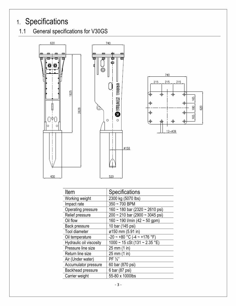
1. Specifications
1.1 General specifications for V30GS
Item Specifications Working weight 2300 kg (5070 lbs)
Impact rate 350 ~ 700 BPM
Operating pressure 160 ~ 180 bar (2320 ~ 2610 psi)
Relief pressure 200 ~ 210 bar (2900 ~ 3045 psi)
Oil flow 160 ~ 190 l/min (42 ~ 50 gpm)
Back pressure 10 bar (145 psi)
Tool diameter ø150 mm (5.91 in)
Oil temperature -20 ~ +80 °C (-4 ~ +176 °F)
Hydraulic oil viscosity 1000 ~ 15 cSt (131 ~ 2.35 °E)
Pressure line size 25 mm (1 in)
Return line size 25 mm (1 in)
Air (Under water) PF ½’’
Accumulator pressure 60 bar (870 psi)
Backhead pressure 6 bar (87 psi)
Carrier weight 55-80 x 1000lbs
- 4 -
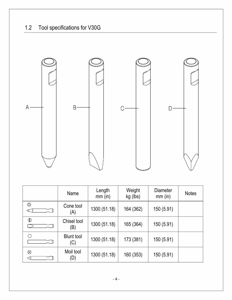
1.2 Tool specifications for V30G
Name Length mm (in)
Weight kg (lbs)
Diameter mm (in)
Notes
Cone tool (A)
1300 (51.18) 164 (362) 150 (5.91)
Chisel tool (B)
1300 (51.18) 165 (364) 150 (5.91)
Blunt tool (C)
1300 (51.18) 173 (381) 150 (5.91)
Moil tool (D)
1300 (51.18) 160 (353) 150 (5.91)

- 5 -
1.3 Structure
1) SIDE ROD
The front head, cylinder and the back head of the breaker body are secured with four side rods.
2) BACK HEAD
The gas charging valve is built in and charged with N2 gas to improve the hammering power.
3) CONTROL VALVE
The control valve is built into the cylinder and it controls the piston’s hammering action.
4) CYLINDER
The cylinder is the heart of the breaker body.
5) PISTON
The kinetic energy of the piston is converted into hammering energy when the piston hits the tool; this
consequently breaks the material.
6) FRONT HEAD
The front head supports the entire breaker with the thrust ring and the built in upper bushing protects the
carrier from the shock transmitted by the tool.
7) TOOL
The cone, chisel, blunt and moil tools can be used in accordance with the application.

- 6 -
2. Operation 2.1 Product numbers
The serial number is stamped on the back head.
It is important make correct reference to the serial number of the attachment when making repairs or
ordering spare parts. Identification of the serial number is the only proper means of identifying parts for
each specific unit.
- 21 -
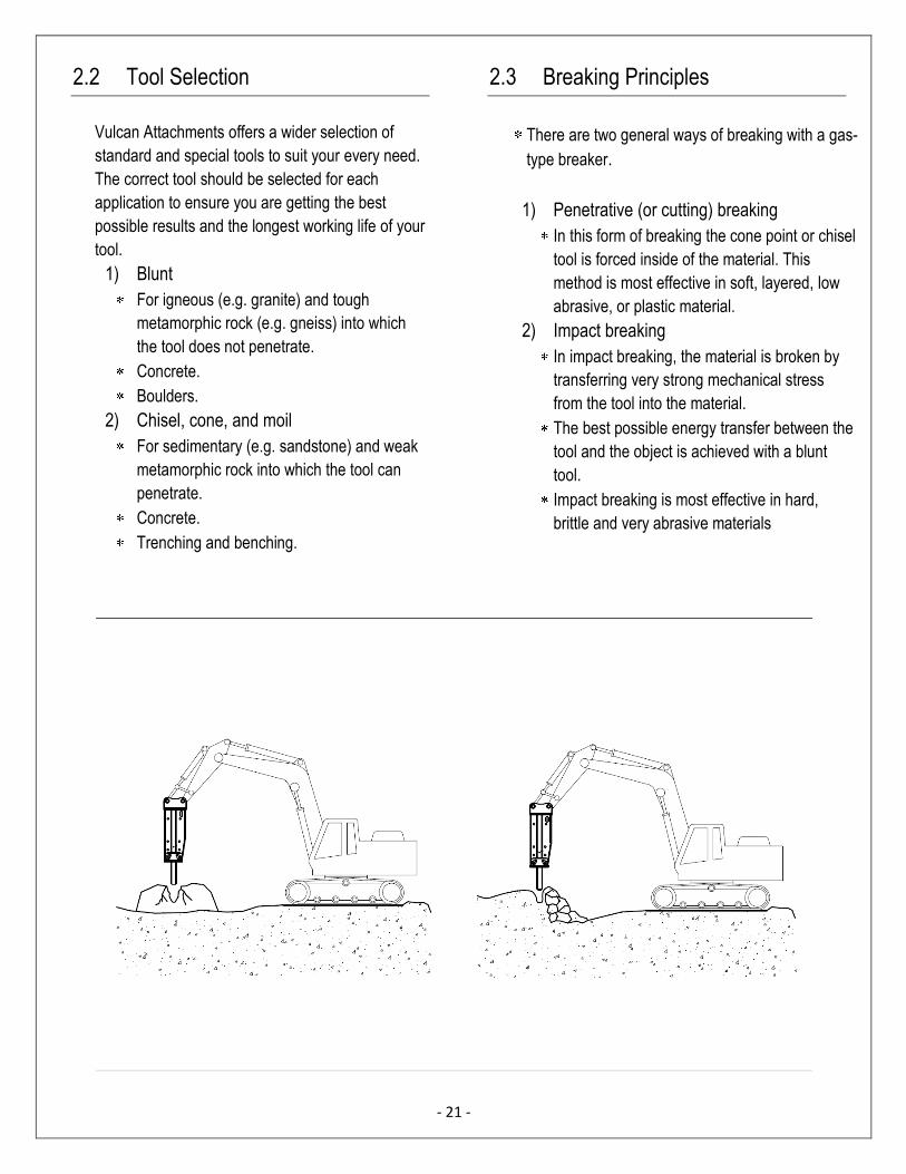
2.2 Tool Selection
Vulcan Attachments offers a wider selection of
standard and special tools to suit your every need.
The correct tool should be selected for each
application to ensure you are getting the best
possible results and the longest working life of your
tool.
1) Blunt
For igneous (e.g. granite) and tough
metamorphic rock (e.g. gneiss) into which
the tool does not penetrate.
Concrete.
Boulders.
2) Chisel, cone, and moil
For sedimentary (e.g. sandstone) and weak
metamorphic rock into which the tool can
penetrate.
Concrete.
Trenching and benching.
2.3 Breaking Principles
There are two general ways of breaking with a gas-
type breaker.
1) Penetrative (or cutting) breaking
In this form of breaking the cone point or chisel
tool is forced inside of the material. This
method is most effective in soft, layered, low
abrasive, or plastic material.
2) Impact breaking
In impact breaking, the material is broken by
transferring very strong mechanical stress
from the tool into the material.
The best possible energy transfer between the
tool and the object is achieved with a blunt
tool.
Impact breaking is most effective in hard,
brittle and very abrasive materials
- 23 -
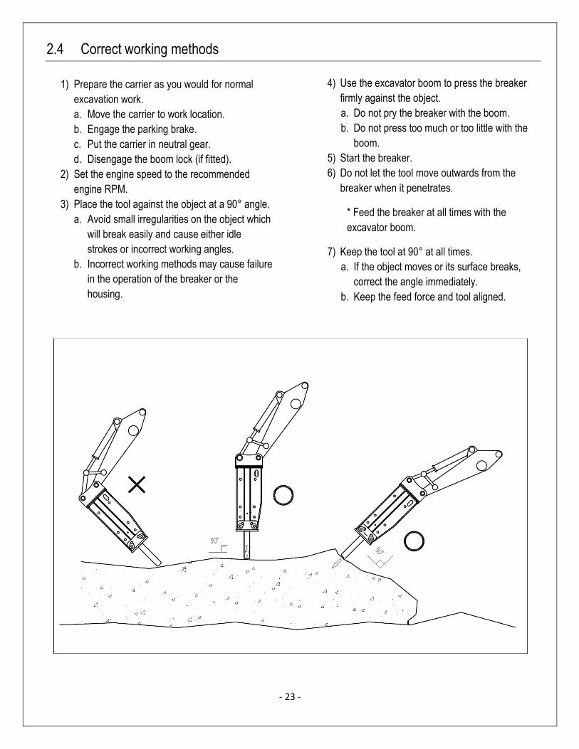
2.4 Correct working methods
1) Prepare the carrier as you would for normal
excavation work.
a. Move the carrier to work location.
b. Engage the parking brake.
c. Put the carrier in neutral gear.
d. Disengage the boom lock (if fitted).
2) Set the engine speed to the recommended
engine RPM.
3) Place the tool against the object at a 90° angle.
a. Avoid small irregularities on the object which
will break easily and cause either idle
strokes or incorrect working angles.
b. Incorrect working methods may cause failure
in the operation of the breaker or the
housing.
4) Use the excavator boom to press the breaker
firmly against the object.
a. Do not pry the breaker with the boom.
b. Do not press too much or too little with the
boom.
5) Start the breaker.
6) Do not let the tool move outwards from the
breaker when it penetrates.
* Feed the breaker at all times with the
excavator boom.
7) Keep the tool at 90° at all times.
a. If the object moves or its surface breaks,
correct the angle immediately.
b. Keep the feed force and tool aligned.

- 23 -
8) Stop the breaker quickly.
a. Do not allow the breaker to fall off the object
or make idle strokes when the object breaks.
Constant idle strokes have a deteriorating
effect on the breaker.
b. If the breaker falls off the object ,side
pressure could occur, and side plates will be
worn down more quickly
9) Chisel, cone, and moil
If the object does not break after fifteen
seconds, stop the beaker and change the
position of the tool. Leaving the tool in the
same position for more that fifteen seconds will
only make an indentation, which will fill with
dust and dampen the impact effect. This will
cause the tool to overheat.
10) When breaking concrete, hard ground, frozen
ground, or any similar material, never strike and pry
with the tool at the same time. This could break the
tool.
2.5 Operating Temperature
The operating temperature is -20°C~80⁰C. If the
temperature is lower than -20°C (-4°F), the
breaker and tool must be preheated before
starting to operate, in order to avoid breakage of
the accumulator membrane and the tool.
During operation they will remain warm.
2.6 Important Operation Points
a. Listen to the breaker’s sound while you are
working.
If the sound becomes thinner and the impact is
less efficient, the tool is misaligned with the
material and/or there is not enough “pressing”
force on the tool.
Realign the tool and press the tool firmly against
the material.
b. The breaker, as a standard assembly must not be
used underwater.
If water fills the space where the piston strikes the
tool, a strong pressure wave is generated and the
breaker could be damaged.
.
- 24 -
2.7 Storage
Long term storage
Observe the following points when the hammer is stored for a long period of time. This will protect the
vital parts of the attachment from rusting, and keeps the machine ready for use whenever it is needed.
1. The storage area must be dry.
2. The tool must be removed from the hammer.
3. The lower end of the piston, tool and the tool bushing must be well protected with grease.
4. Connections must be sealed with clean plugs to prevent oil leakage and dirt from getting into the
couplings.
5. The breaker must be stored in the vertical position.
6. Ensure that the breaker can not fall over.

- 25 -
2.8 Mounting and Dismounting the Hammer
Removal from the carrier
1. Position the hammer horizontally on the floor and remove the tool.
2. Stop the carrier engine. Operate boom and hammer controls to release the trapped pressure inside
of the hoses. Wait ten minutes for the oil pressure to drop.
3. Close the hammer inlet and outlet lines. If quick couplers are used, disconnection automatically
closes the hammer lines.
4. Disconnect the hoses and plug them as well as the hammer inlet and outlet ports.
5. Remove the bucket pins and other parts.
6. The carrier can now be moved aside.
Installation
1. Install the hammer in the same manner as mounting a bucket, install bucket pins.
2. Connect the hoses. Hammer inlet port is marked on the back head with “IN” and the outlet port is
marked with “OUT”.
3. Open the hammer inlet and outlet lines.
- 26 -
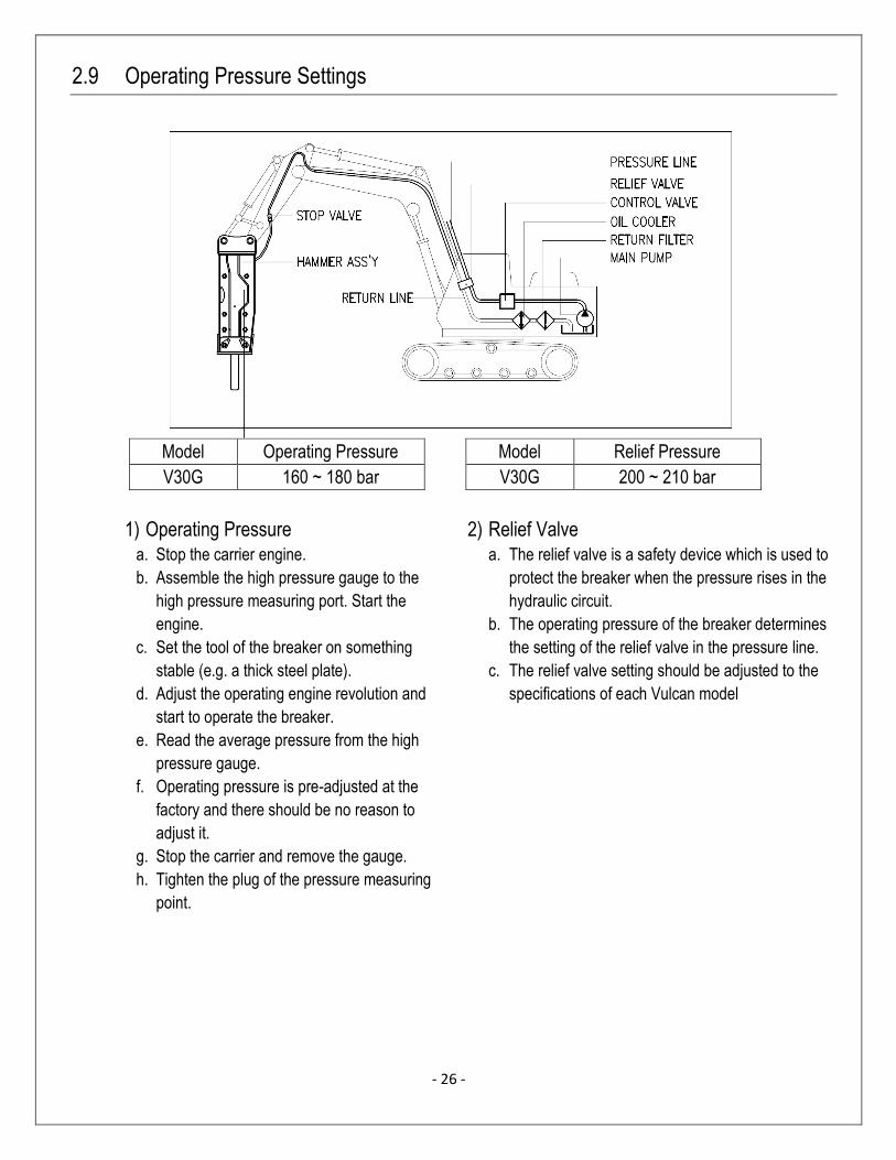
2.9 Operating Pressure Settings
Model Operating Pressure
V30G 160 ~ 180 bar
1) Operating Pressure a. Stop the carrier engine.
b. Assemble the high pressure gauge to the
high pressure measuring port. Start the
engine.
c. Set the tool of the breaker on something
stable (e.g. a thick steel plate).
d. Adjust the operating engine revolution and
start to operate the breaker.
e. Read the average pressure from the high
pressure gauge.
f. Operating pressure is pre-adjusted at the
factory and there should be no reason to
adjust it.
g. Stop the carrier and remove the gauge.
h. Tighten the plug of the pressure measuring
point.
Model Relief Pressure
V30G 200 ~ 210 bar
2) Relief Valve a. The relief valve is a safety device which is used to
protect the breaker when the pressure rises in the
hydraulic circuit.
b. The operating pressure of the breaker determines
the setting of the relief valve in the pressure line.
c. The relief valve setting should be adjusted to the
specifications of each Vulcan model
- 27 -
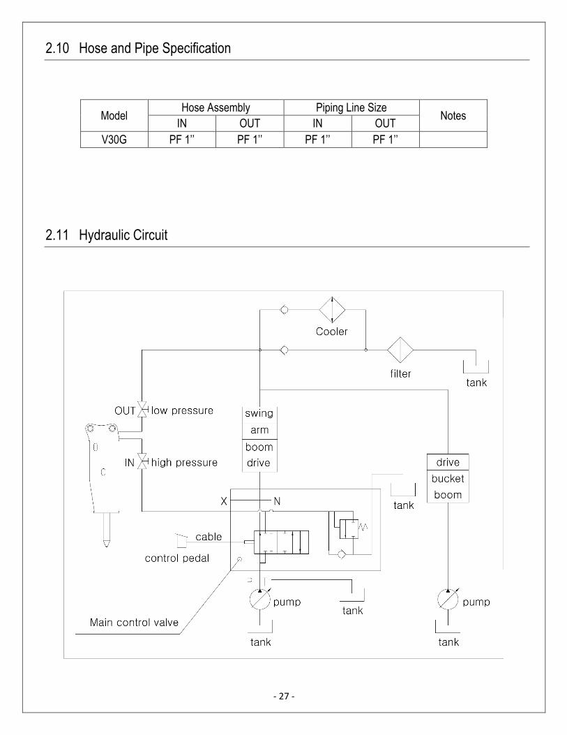
2.10 Hose and Pipe Specification
Model Hose Assembly Piping Line Size
Notes IN OUT IN OUT
V30G PF 1’’ PF 1’’ PF 1’’ PF 1’’
2.11 Hydraulic Circuit

3. Lubrication 3.1 Manual Lubrication
* Grease interval
1. The tool shank must be well lubricated before installing the tool.
2. Apply 5 – 10 strokes from the grease gun to the tool bushing and the tool at regular intervals.
3. Adapt the interval and amount of grease to decrease the wearing of the tool and keep it in good working
condition.
Greasing should be done every 2 hours.
Insufficient greasing or improper grease could cause:
- Abnormal wear of the tool bushing and the tool.
- Tool breakage.
Technical data:
- NLGI grade 2.
- Synthetic oil base with aluminum complex soap.
- Approximately 15% graphite copper solids to reduce metal to metal contact damage.
- Dropping point 260°C (500°F).
- Viscosity 15 cSt.
- Temperature range -30° ~ 230°C (-20°F ~ 450°F).
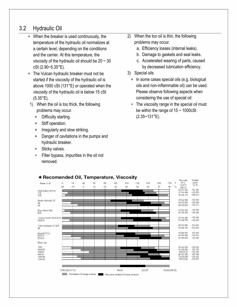
3.2 Hydraulic Oil
When the breaker is used continuously, the
temperature of the hydraulic oil normalizes at
a certain level, depending on the conditions
and the carrier. At this temperature, the
viscosity of the hydraulic oil should be 20 ~ 30
cSt (2.90~5.35°E).
The Vulcan hydraulic breaker must not be
started if the viscosity of the hydraulic oil is
above 1000 cSt (131°E) or operated when the
viscosity of the hydraulic oil is below 15 cSt
(5.35°E).
1) When the oil is too thick, the following
problems may occur.
Difficulty starting.
Stiff operation.
Irregularly and slow striking.
Danger of cavitations in the pumps and
hydraulic breaker.
Sticky valves.
Filter bypass, impurities in the oil not
removed.
2) When the too oil is thin, the following
problems may occur.
a. Efficiency losses (internal leaks).
b. Damage to gaskets and seal leaks.
c. Accelerated wearing of parts, caused
by decreased lubrication efficiency.
3) Special oils
In some cases special oils (e.g. biological
oils and non-inflammable oil) can be used.
Please observe following aspects when
considering the use of special oil:
The viscosity range in the special oil must
be within the range of 15 ~ 1000cSt
(2.35~131°E).
- 30 -
4) Cleanliness of the hydraulic oil
The hydraulic oil filter of the carrier will
clean the oil flowing through the
breaker.
The purpose of the oil filter is to
remove impurities from the hydraulic
oil since they accelerate component
wear, cause blockages and even
seizure.
Impurities also cause the oil to
overheat and deteriorate.
Air and water are impurities in oil.
5) Oil filter
When working with the hydraulic
breaker, the carrier oil filter must fulfill
the following specifications:
a. The oil filter must be rated at 25
microns maximum.
b. The oil filter must be a standard
return line filter rated to maximum
working pressure.
c. The oil filter must have a volume
flow capacity of at least twice the
breaker’s maximum flow.
d. The cooler must withstand a
dynamic pressure of 290 psi (20
bar).
6) If the carrier’s oil cooler is too small, the
original cooler must be replaced with a
larger one or an auxiliary cooler must be
installed. The auxiliary hydraulic cooler
can be installed:
a. In front of the radiator, in which case
an additional fan is not required, i.e.
maximum rise of cooling air is 5°C
(40°F).
b. Any other suitable place, using a fan
either hydraulically of electrically
driven
7) Damage caused by hydraulic oil
contamination in the carrier and breaker
circuits causes:
a. The working life of the pumps to be
significantly shortened.
- Premature wear of the parts.
- Cavitation.
b. Valves do not function properly.
- Spools bind – premature wear of the
parts.
- Blocking of small holes.
c. Wear of the cylinders.
d. Reduced breaker efficiency.
- Premature wear of moving parts and
seals.
- Danger of the piston seizing and
the oil overheating.
e. Shortened working life and reduced
efficiency of hydraulic oil.
- Oil overheats and the oil quality
deteriorates.
- Electro-chemical changes in the
hydraulic oil.
- 23 -
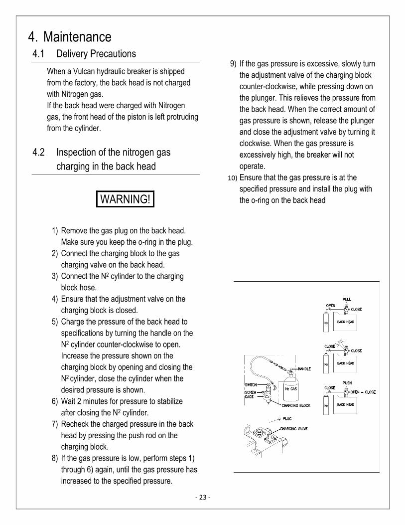
4. Maintenance 4.1 Delivery Precautions
When a Vulcan hydraulic breaker is shipped
from the factory, the back head is not charged
with Nitrogen gas.
If the back head were charged with Nitrogen
gas, the front head of the piston is left protruding
from the cylinder.
4.2 Inspection of the nitrogen gas
charging in the back head
WARNING!
1) Remove the gas plug on the back head.
Make sure you keep the o-ring in the plug.
2) Connect the charging block to the gas
charging valve on the back head.
3) Connect the N2 cylinder to the charging
block hose.
4) Ensure that the adjustment valve on the
charging block is closed.
5) Charge the pressure of the back head to
specifications by turning the handle on the
N2 cylinder counter-clockwise to open.
Increase the pressure shown on the
charging block by opening and closing the
N2 cylinder, close the cylinder when the
desired pressure is shown.
6) Wait 2 minutes for pressure to stabilize
after closing the N2 cylinder.
7) Recheck the charged pressure in the back
head by pressing the push rod on the
charging block.
8) If the gas pressure is low, perform steps 1)
through 6) again, until the gas pressure has
increased to the specified pressure.
9) If the gas pressure is excessive, slowly turn
the adjustment valve of the charging block
counter-clockwise, while pressing down on
the plunger. This relieves the pressure from
the back head. When the correct amount of
gas pressure is shown, release the plunger
and close the adjustment valve by turning it
clockwise. When the gas pressure is
excessively high, the breaker will not
operate.
10) Ensure that the gas pressure is at the
specified pressure and install the plug with
the o-ring on the back head
- 23 -
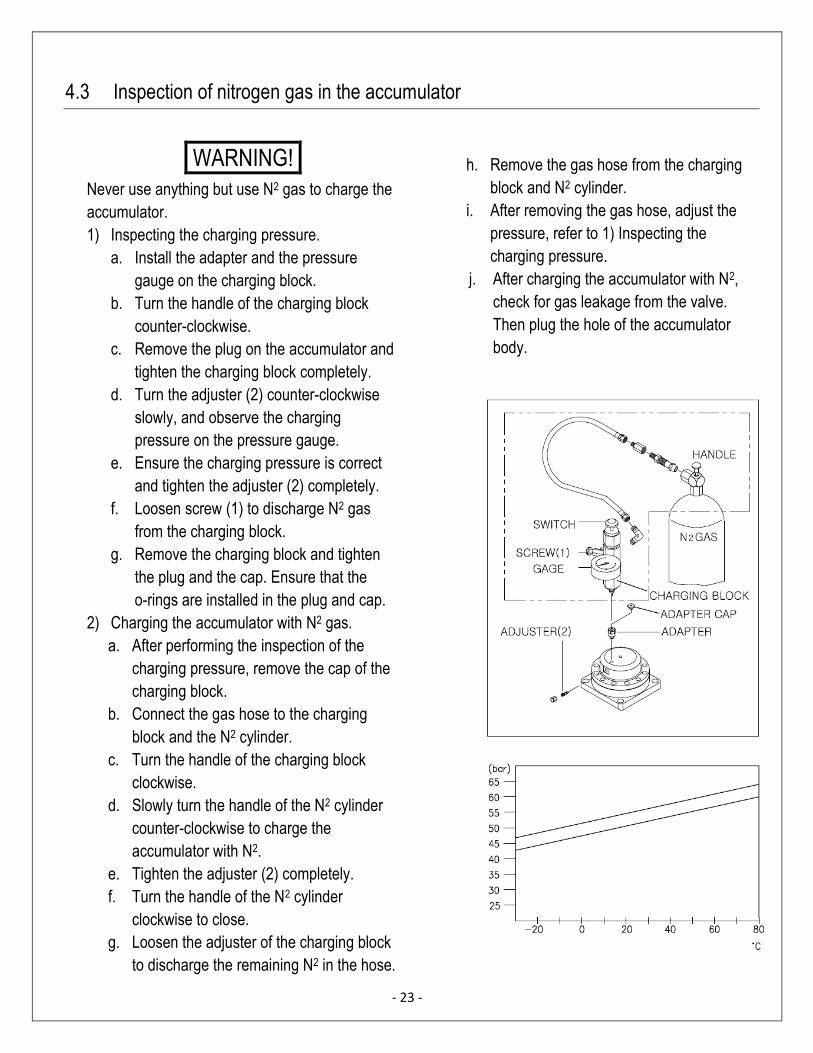
4.3 Inspection of nitrogen gas in the accumulator
WARNING!
Never use anything but use N2 gas to charge the
accumulator.
1) Inspecting the charging pressure.
a. Install the adapter and the pressure
gauge on the charging block.
b. Turn the handle of the charging block
counter-clockwise.
c. Remove the plug on the accumulator and
tighten the charging block completely.
d. Turn the adjuster (2) counter-clockwise
slowly, and observe the charging
pressure on the pressure gauge.
e. Ensure the charging pressure is correct
and tighten the adjuster (2) completely.
f. Loosen screw (1) to discharge N2 gas
from the charging block.
g. Remove the charging block and tighten
the plug and the cap. Ensure that the
o-rings are installed in the plug and cap.
2) Charging the accumulator with N2 gas.
a. After performing the inspection of the
charging pressure, remove the cap of the
charging block.
b. Connect the gas hose to the charging
block and the N2 cylinder.
c. Turn the handle of the charging block
clockwise.
d. Slowly turn the handle of the N2 cylinder
counter-clockwise to charge the
accumulator with N2.
e. Tighten the adjuster (2) completely.
f. Turn the handle of the N2 cylinder
clockwise to close.
g. Loosen the adjuster of the charging block
to discharge the remaining N2 in the hose.
h. Remove the gas hose from the charging
block and N2 cylinder.
i. After removing the gas hose, adjust the
pressure, refer to 1) Inspecting the
charging pressure.
j. After charging the accumulator with N2,
check for gas leakage from the valve.
Then plug the hole of the accumulator
body.

- 23 -
4.4 Side Rod Inspection and Replacement
CAUTION!
Release the back head pressure completely before loosening the side rods. Not releasing the pressure in
the back head before removing the side rods can cause damage to the unit and serious bodily harm.
1) Discharge the N2 in the back head completely before loosening the side rods.
2) Remove all of the side rods, and inspect them for any cracks or damage.
3) When installing the side rods, tighten the bolts one turn at a time in a diagonal sequence, not each nut
completely before the next.
4) Use the torque wrench to tighten each nut to their specified torque range.
4.5 Adjusting Control Methods
An adjuster which regulates the number of blows is standard in Vulcan hydraulic breakers.
For the most effective breaking, change the number of blows depending on the working condition.
By using an adjuster, piston stroke and frequency can be controlled, meanwhile keeping the working
pressure and flow rate of the oil fixed.
The adjuster is installed on the right side of the cylinder.
To control the adjuster, rotate the adjusting screw by loosening the lock nut from the head of the
adjustment screw first.
Rotating the screw clockwise to the end makes the longest stroke and minimum number of blows, while
rotating the screw counter-clockwise two (2) turns makes the shortest stroke and gives the maximum
number of blows.
After adjustment, tighten the lock nut completely.
- 23 -
4.6 Regulating oil flow rate of valve adjuster
When the base machine supplies insufficient hydraulic oil to the breaker, this adjusting valve can obtain
the rated working pressure by reducing the number of blows; even though the working pressure is
continuously the same, if the oil flow to the hammer is increased the number of blows would also be
increased.
Vulcan breakers are being sent out with adjuster’s preset at 3 to 4 turns counter-clockwise as the
standard specification.
- 23 -
4.7 Wearing parts
1) When damaged or worn, it is highly
recommended to replace the following
wearable parts:
- Tool
- Tool bushing (must be removed at the
service centre)
- Tool pins
- Stopper pin, bushing pin
- Rubber plug, bushing pin plug
- Hydraulic seals
- Side bolts
- Hydraulic hoses
2) We recommend the user to stock wearable
parts such as tool pins, stoppers, rubber
plugs, bolts and hydraulic hoses.
3) Replace hydraulic seals after every 600
hours of actual operation.
4) Tool pin
- When each tool pin is excessively
deformed, it is difficult to replace the tool.
Therefore, every 100 to 150 hours of
operation, change the face of each pin
which comes in contact with the tool. The
two faces of each pin can be used. If the
tool you use is not a genuine part, we can
not guarantee the breaker unit and part’s
performance.
- When replacing each part, check for wear,
breakage, scours, etc., especially after
removing burrs and swelling on tool pins.
- Replace the tool after grinding the worn
parts of the tool pin. Insert a new tool pin
after grinding the scuffed parts of the tool
and tool pins in use.
- 23 -
4.8 Wear limit of tool and tool bushing
When the clearance between the tool and the tool bushing becomes excessive, it is strongly
recommended that these parts are replaced to prevent further wearing of the components.
To use the tool and tool bushing past their wear limit, can cause damage to other parts of the breaker
such as the piston or the cylinder.
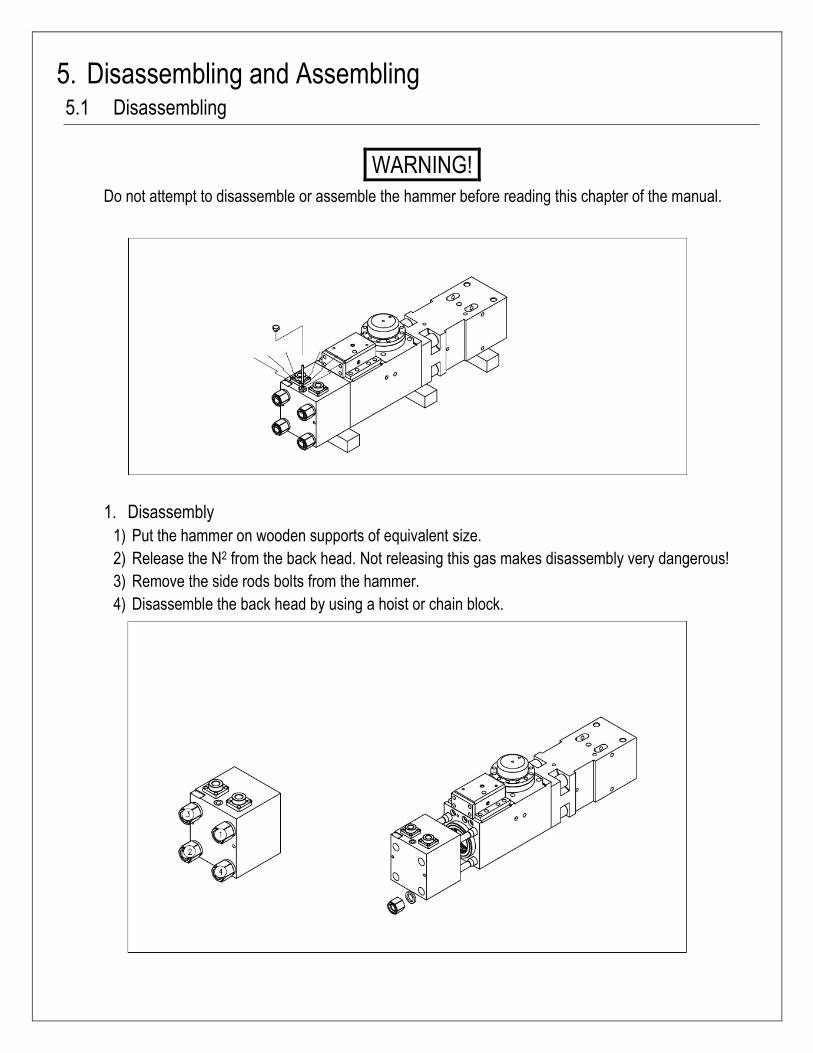
5. Disassembling and Assembling 5.1 Disassembling
WARNING!
Do not attempt to disassemble or assemble the hammer before reading this chapter of the manual.
1. Disassembly
1) Put the hammer on wooden supports of equivalent size.
2) Release the N2 from the back head. Not releasing this gas makes disassembly very dangerous!
3) Remove the side rods bolts from the hammer.
4) Disassemble the back head by using a hoist or chain block.
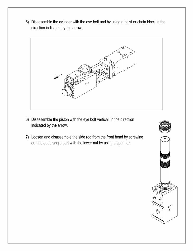
5) Disassemble the cylinder with the eye bolt and by using a hoist or chain block in the
direction indicated by the arrow.
6) Disassemble the piston with the eye bolt vertical, in the direction
indicated by the arrow.
7) Loosen and disassemble the side rod from the front head by screwing
out the quadrangle part with the lower nut by using a spanner.
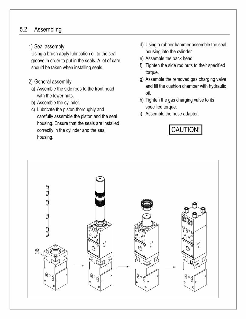
5.2 Assembling
1) Seal assembly
Using a brush apply lubrication oil to the seal
groove in order to put in the seals. A lot of care
should be taken when installing seals.
2) General assembly
a) Assemble the side rods to the front head
with the lower nuts.
b) Assemble the cylinder.
c) Lubricate the piston thoroughly and
carefully assemble the piston and the seal
housing. Ensure that the seals are installed
correctly in the cylinder and the seal
housing.
d) Using a rubber hammer assemble the seal
housing into the cylinder.
e) Assemble the back head.
f) Tighten the side rod nuts to their specified
torque.
g) Assemble the removed gas charging valve
and fill the cushion chamber with hydraulic
oil.
h) Tighten the gas charging valve to its
specified torque.
i) Assemble the hose adapter.
CAUTION!

- 23 -
5.3 Torques
Item N.m kg.m ft.lb Description Qty
A 2,500 250 1,840 Side rod nut 4
B 450 45 330 Accumulator cover bolt 12
C 800 80 590 Accumulator bottom bolt 4
D 450 45 330 Valve block bolt 8
E 450 45 330 Valve block cover bolt 8
F 200 20 150 Flange adapter bolt 8
G 2,500 250 1,845 Joint nut 8
H 800 80 590 Top cover bolt 12

5.4 Workshop tool list
NO. Part Name Specifications Qty Notes
1 Tool Box Large Size 1
2 Single Spanner 19mm 1
3 Single Spanner 22mm 1
4 Single Spanner 32mm 1
5 Hammer Wrench 70mm 1
6 Hammer Wrench 75mm 1
7 L - Wrench 5mm 1
8 L - Wrench 10mm 1
9 L - Wrench 14mm 1
10 L – Wrench 17mm 1
11 L – Wrench 19mm 1
12 Driver (+) 1 pc
13 Driver (-) 1 pc
14 Installation Card 2 set
15 Warranty Claim Report 2 set
16 Hammer Card 1 set
17 Gas Charging Kit 1 set Option Part
18 Gas Cylinder 3.4 liter Option Part
19 Seal Kit 1 set Option Part
6. Troubleshooting Guide 6.1 Oil leakage
6.2 No impact
Probable cause Remedy
a. Oil temperature is too low. b. Valve does not operate properly c. Pressure in the back head and setting pressure
of the relief valve is too low.
d. Poor performance of the hydraulic pump.
- Oil temperature must reach a minimum of 30⁰C - Check the breaker operating button in the cabin. - Check the pressure of the nitrogen gas and the
relief valve. - Contact the excavator manufacturer.
Probable cause Remedy
a. Oil leakage between the tool and the tool
bushing.
b. Oil leakage on the surface of the breaker. c. Oil leakages on the valve block and bolts.
d. Oil leakage between the cylinder and the back head.
- Replace the damaged seals.
- Retighten the loose breaker hoses and bolts.
- This is normal, during assembly lubrication and antirust oil is applied.
- Tighten to specified torque.
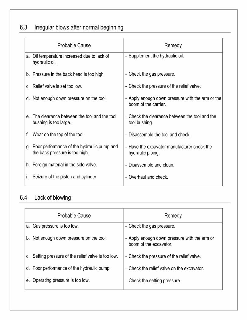
6.3 Irregular blows after normal beginning
Probable Cause Remedy
a. Oil temperature increased due to lack of hydraulic oil.
b. Pressure in the back head is too high. c. Relief valve is set too low. d. Not enough down pressure on the tool. e. The clearance between the tool and the tool
bushing is too large. f. Wear on the top of the tool. g. Poor performance of the hydraulic pump and
the back pressure is too high. h. Foreign material in the side valve.
i. Seizure of the piston and cylinder.
- Supplement the hydraulic oil. - Check the gas pressure.
- Check the pressure of the relief valve. - Apply enough down pressure with the arm or the
boom of the carrier. - Check the clearance between the tool and the
tool bushing.
- Disassemble the tool and check. - Have the excavator manufacturer check the
hydraulic piping. - Disassemble and clean. - Overhaul and check.
6.4 Lack of blowing
Probable Cause Remedy
a. Gas pressure is too low.
b. Not enough down pressure on the tool.
c. Setting pressure of the relief valve is too low.
d. Poor performance of the hydraulic pump.
e. Operating pressure is too low.
- Check the gas pressure.
- Apply enough down pressure with the arm or boom of the excavator.
- Check the pressure of the relief valve.
- Check the relief valve on the excavator.
- Check the setting pressure.
- 23 -
7. Generals and Safety information 7.1 General
Do not use or install the breaker until you can use
the carrier. Do not rush the learning process. Take
your time and learn how to operate the breaker
safely and efficiently.
If there is anything you do not understand, ask
your Vulcan service center for advice.
The breaker serial number is stamped on a metal
plate which is located on the back head near the
inlet connection.
Correct reference to the serial number of the
breaker is important when ordering spare parts.
Identifying parts for specific breaker’s is only
possible through the serial number.
7.2 Safety
1) Manuals
a. Read this manual before installing, operating,
or maintaining the breaker. If there is anything
that you do not understand ask your employer
or your local Vulcan dealer.
b. Keep this manual in good condition for future
reference.
2) Clothing
a. Proper clothing is important to prevent injury.
Loose clothing can get caught in the machinery
and cause bodily harm.
3) Work site
a. Inspect the working site before starting work.
b. Check for potholes, weak ground, hidden rocks
etc.
c. Check for utilities like water pipes, power lines,
and gas lines.
4) Metal splinters
a. Injury can be caused by flying splinters when
driving metal pins in and out.
b. Always wear safety glasses.
5) Accumulator
a. The accumulator is pressurized even when
there is no hydraulic pressure in the breaker.
b. Attempting to dismantle the accumulator
without first releasing the pressure can cause
serious injury.
c. Do not try to dismantle the pressure
accumulator, contact your Vulcan service
center first.
6) Hydraulic pressure
a. Hydraulic fluid at system pressure is very
dangerous.
b. Before disconnecting or connecting the
hydraulic hoses, stop the carrier engine and
operate the controls to release the pressure
trapped in the hoses.
c. Keep all personnel away from the hydraulic
hoses during breaker operation.
- Regulation –
Observe all of the laws, work site and local
regulations which affect you and your equipment.
- Practice –
Carrying out unfamiliar actions without practice
could cause serious injury to the operator and
any others on site.
Practice away from the job site in a clear area.
Keep other people away.
Do not perform new operations until you are
confident you can carry them out safely.
- Equipment condition –
Defective equipment can cause injury to yourself
and others. Do not operate equipment that is
defective or has missing parts.
Make sure that the maintenance procedures in
this manual are completed before operation.
- Equipment limits –
Operating the equipment beyond it’ design limits
can cause damage and be hazardous.
Do not operate the equipment beyond its limits.
Do not try to upgrade the equipment’s
performance with non-approved modifications.
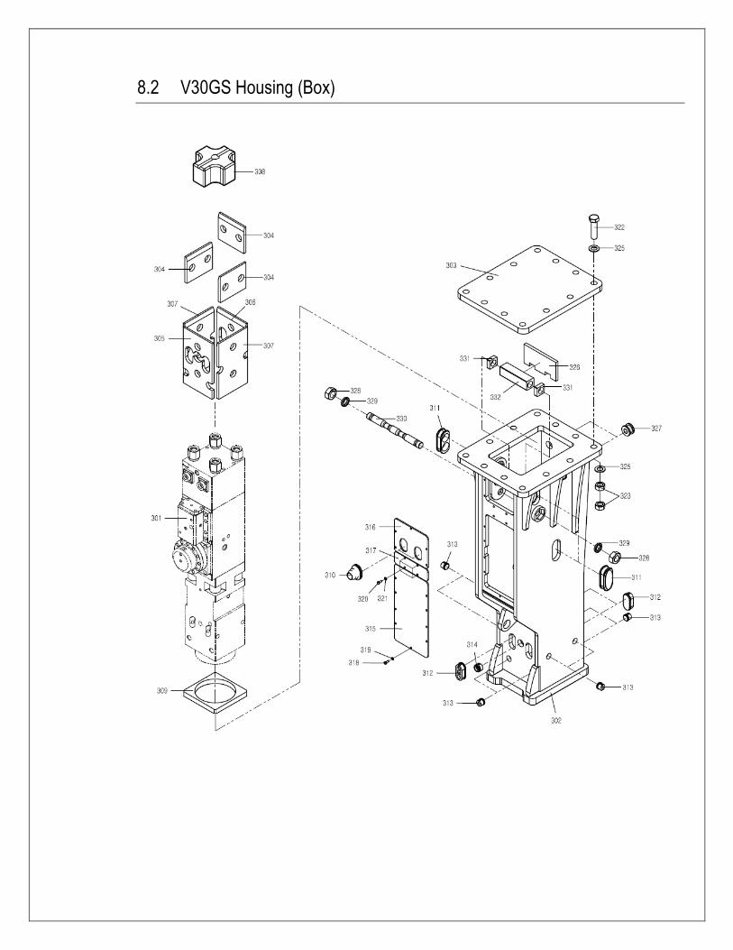
8.2 V30GS Housing (Box)
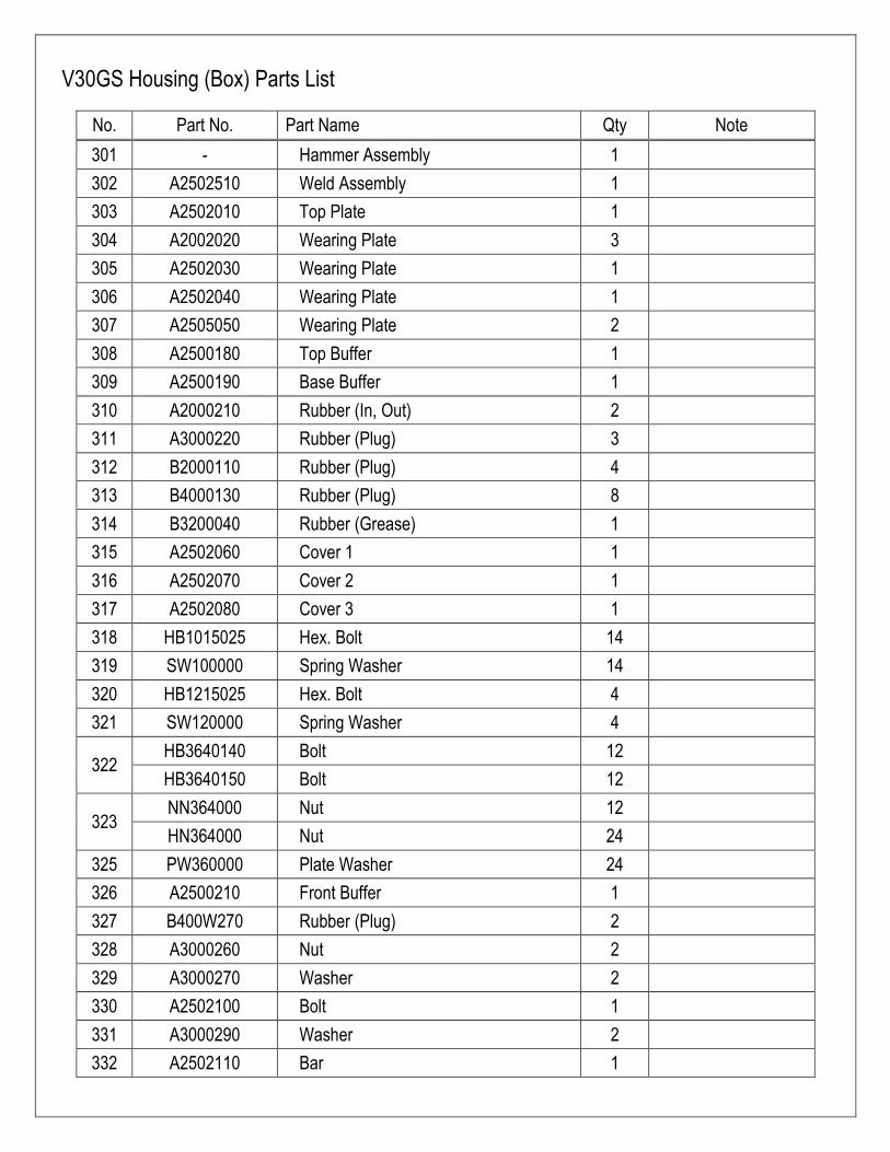
V30GS Housing (Box) Parts List
No. Part No. Part Name Qty Note
301 - Hammer Assembly 1
302 A2502510 Weld Assembly 1
303 A2502010 Top Plate 1
304 A2002020 Wearing Plate 3
305 A2502030 Wearing Plate 1
306 A2502040 Wearing Plate 1
307 A2505050 Wearing Plate 2
308 A2500180 Top Buffer 1
309 A2500190 Base Buffer 1
310 A2000210 Rubber (In, Out) 2
311 A3000220 Rubber (Plug) 3
312 B2000110 Rubber (Plug) 4
313 B4000130 Rubber (Plug) 8
314 B3200040 Rubber (Grease) 1
315 A2502060 Cover 1 1
316 A2502070 Cover 2 1
317 A2502080 Cover 3 1
318 HB1015025 Hex. Bolt 14
319 SW100000 Spring Washer 14
320 HB1215025 Hex. Bolt 4
321 SW120000 Spring Washer 4
322 HB3640140 Bolt 12
HB3640150 Bolt 12
323 NN364000 Nut 12
HN364000 Nut 24
325 PW360000 Plate Washer 24
326 A2500210 Front Buffer 1
327 B400W270 Rubber (Plug) 2
328 A3000260 Nut 2
329 A3000270 Washer 2
330 A2502100 Bolt 1
331 A3000290 Washer 2
332 A2502110 Bar 1
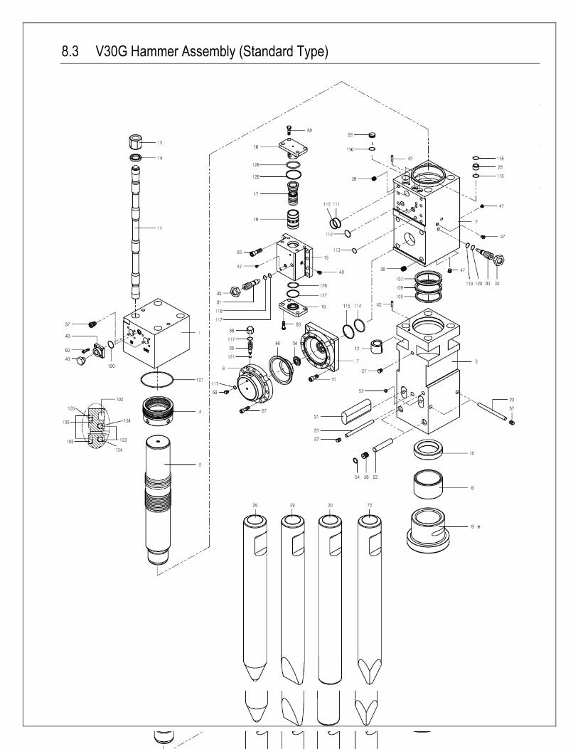
8.3 V30G Hammer Assembly (Standard Type)
8.4 V30G Hammer Assembly (Standard Type)
8.5 V30G Hammer Assembly (Standard Type)
8.6 V30G Hammer Assembly (Standard Type)
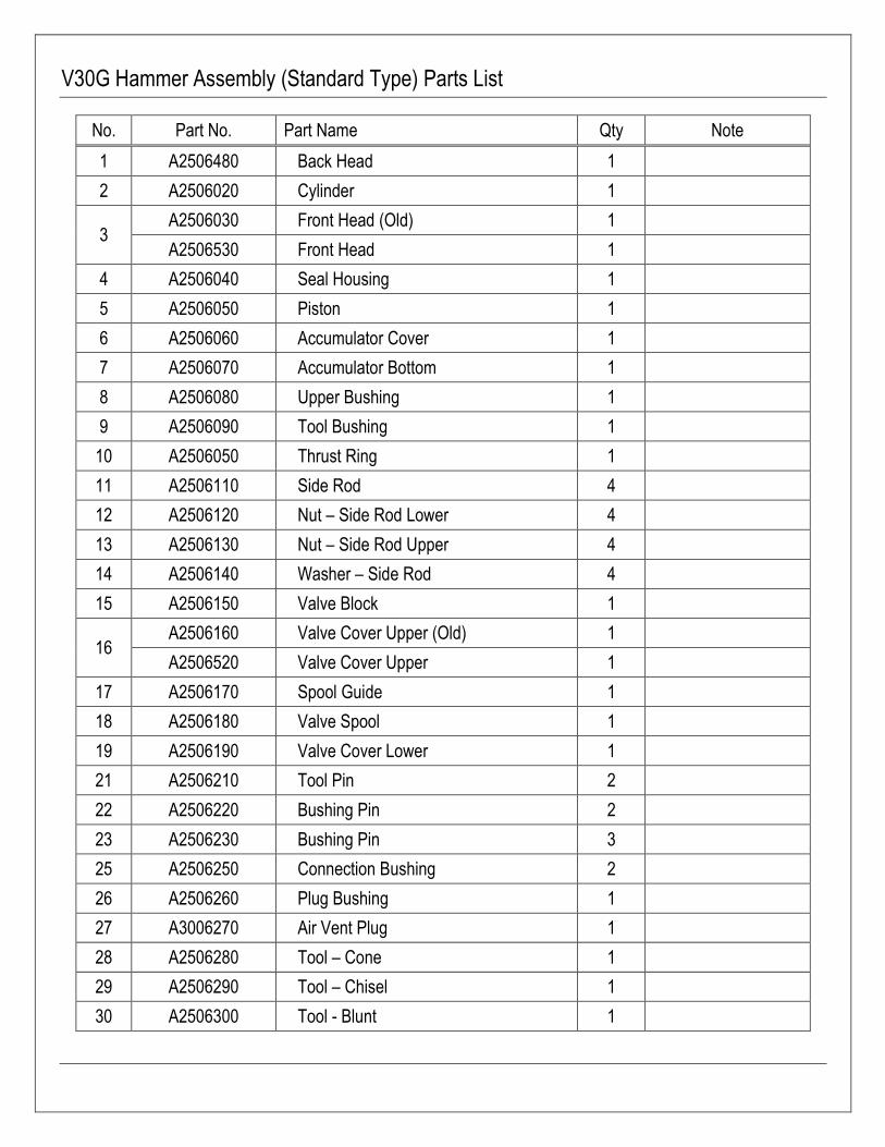
V30G Hammer Assembly (Standard Type) Parts List
No. Part No. Part Name Qty Note
1 A2506480 Back Head 1
2 A2506020 Cylinder 1
3 A2506030 Front Head (Old) 1
A2506530 Front Head 1
4 A2506040 Seal Housing 1
5 A2506050 Piston 1
6 A2506060 Accumulator Cover 1
7 A2506070 Accumulator Bottom 1
8 A2506080 Upper Bushing 1
9 A2506090 Tool Bushing 1
10 A2506050 Thrust Ring 1
11 A2506110 Side Rod 4
12 A2506120 Nut – Side Rod Lower 4
13 A2506130 Nut – Side Rod Upper 4
14 A2506140 Washer – Side Rod 4
15 A2506150 Valve Block 1
16 A2506160 Valve Cover Upper (Old) 1
A2506520 Valve Cover Upper 1
17 A2506170 Spool Guide 1
18 A2506180 Valve Spool 1
19 A2506190 Valve Cover Lower 1
21 A2506210 Tool Pin 2
22 A2506220 Bushing Pin 2
23 A2506230 Bushing Pin 3
25 A2506250 Connection Bushing 2
26 A2506260 Plug Bushing 1
27 A3006270 Air Vent Plug 1
28 A2506280 Tool – Cone 1
29 A2506290 Tool – Chisel 1
30 A2506300 Tool - Blunt 1
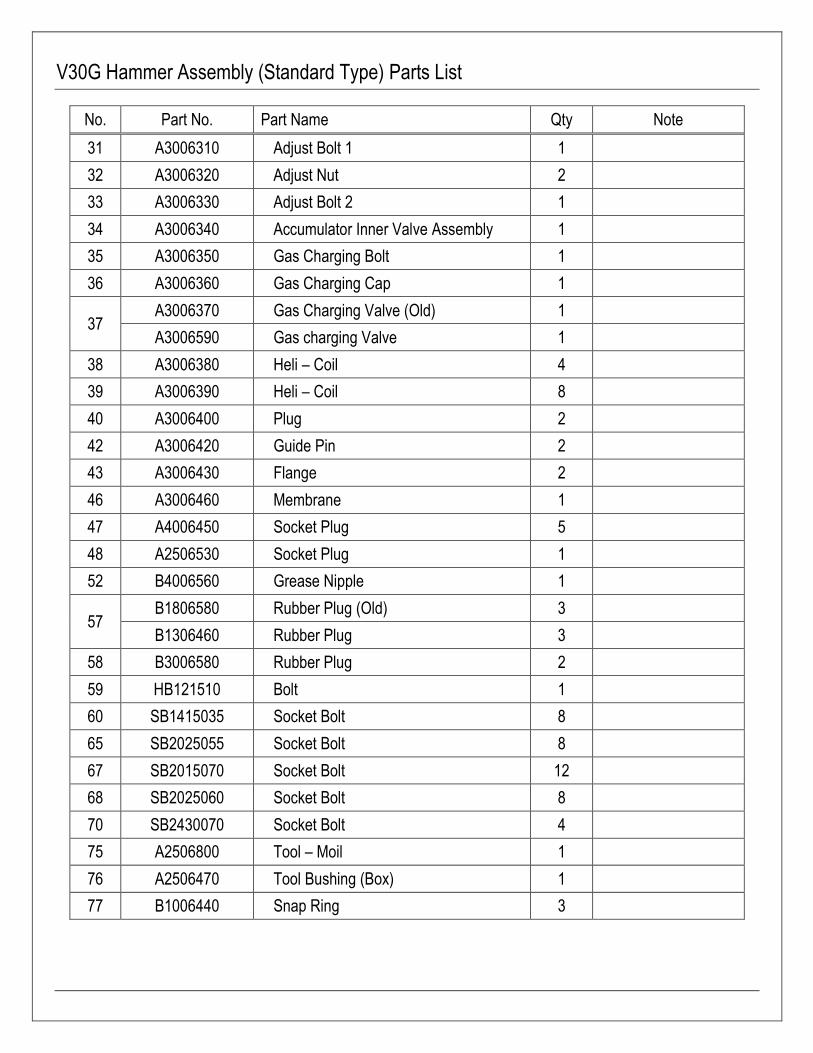
V30G Hammer Assembly (Standard Type) Parts List
No. Part No. Part Name Qty Note
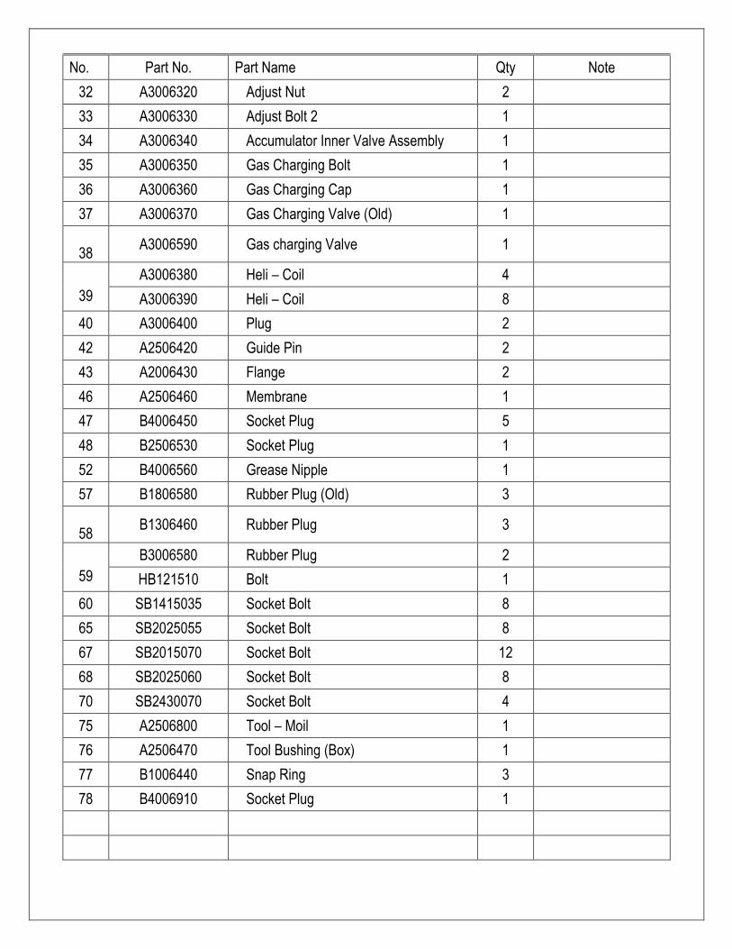
31 A3006310 Adjust Bolt 1 1
32 A3006320 Adjust Nut 2
33 A3006330 Adjust Bolt 2 1
34 A3006340 Accumulator Inner Valve Assembly 1
35 A3006350 Gas Charging Bolt 1
36 A3006360 Gas Charging Cap 1
37 A3006370 Gas Charging Valve (Old) 1
A3006590 Gas charging Valve 1
38 A3006380 Heli – Coil 4
39 A3006390 Heli – Coil 8
40 A3006400 Plug 2
42 A3006420 Guide Pin 2
43 A3006430 Flange 2
46 A3006460 Membrane 1
47 A4006450 Socket Plug 5
48 A2506530 Socket Plug 1
52 B4006560 Grease Nipple 1
57 B1806580 Rubber Plug (Old) 3
B1306460 Rubber Plug 3
58 B3006580 Rubber Plug 2
59 HB121510 Bolt 1
60 SB1415035 Socket Bolt 8
65 SB2025055 Socket Bolt 8
67 SB2015070 Socket Bolt 12
68 SB2025060 Socket Bolt 8
70 SB2430070 Socket Bolt 4
75 A2506800 Tool – Moil 1
76 A2506470 Tool Bushing (Box) 1
77 B1006440 Snap Ring 3
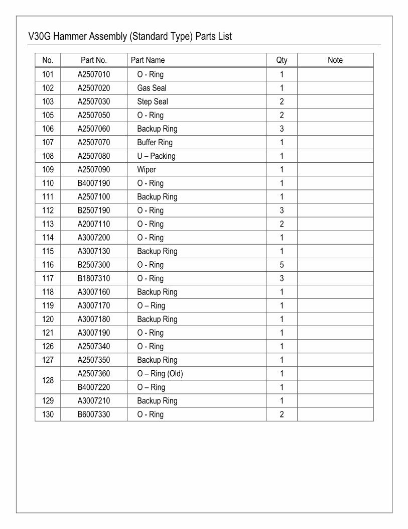
V30G Hammer Assembly (Standard Type) Parts List
No. Part No. Part Name Qty Note
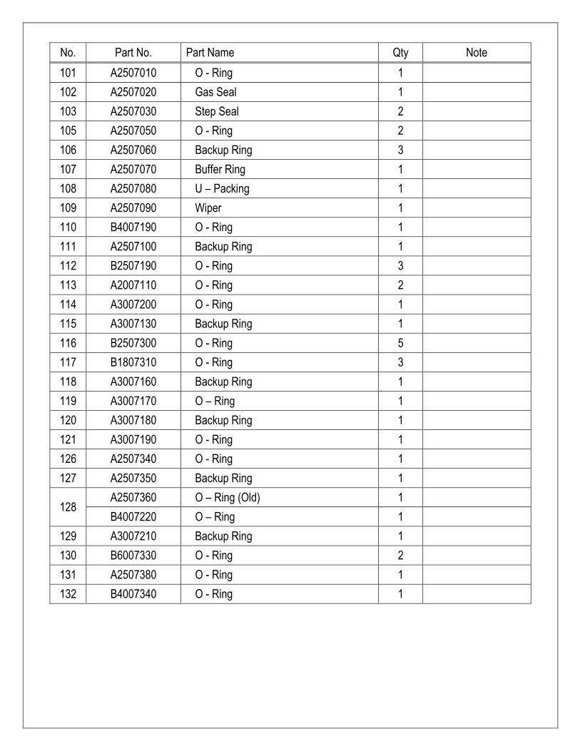
101 A2507010 O - Ring 1
102 A2507020 Gas Seal 1
103 A2507030 Step Seal 2
105 A2507050 O - Ring 2
106 A2507060 Backup Ring 3
107 A2507070 Buffer Ring 1
108 A2507080 U – Packing 1
109 A2507090 Wiper 1
110 B4007190 O - Ring 1
111 A2507100 Backup Ring 1
112 B2507190 O - Ring 3
113 A2007110 O - Ring 2
114 A3007200 O - Ring 1
115 A3007130 Backup Ring 1
116 B2507300 O - Ring 5
117 B1807310 O - Ring 3
118 A3007160 Backup Ring 1
119 A3007170 O – Ring 1
120 A3007180 Backup Ring 1
121 A3007190 O - Ring 1
126 A2507340 O - Ring 1
127 A2507350 Backup Ring 1
128 A2507360 O – Ring (Old) 1
B4007220 O – Ring 1
129 A3007210 Backup Ring 1
130 B6007330 O - Ring 2

8.3 V30G Hammer Assembly (Auto grease type)

V30G Hammer Assembly (Auto grease type) Parts List
No. Part No. Part Name Qty Note
1 A2506490 Back Head 1
2 A2506500 Cylinder 1
3 A2506510 Front Head (Old) 1
A2506540 Front Head 1
4 A2506040 Seal Housing 1
5 A2506050 Piston 1
6 A2506060 Accumulator Cover 1
7 A2506070 Accumulator Bottom 1
8 A2506080 Upper Bushing 1
9 A2506090 Tool Bushing 1
10 A2506100 Thrust Ring 1
11 A2506110 Side Rod 4
12 A2506120 Nut – Side Rod Lower 4
13 A2506130 Nut – Side Rod Upper 4
14 A2506140 Washer – Side Rod 4
15 A2506150 Valve Block 1
16 A2506160 Valve Cover Upper (Old) 1
A2506520 Valve Cover Upper 1
17 A2506170 Spool Guide 1
18 A2506180 Valve Spool 1
19 A2506190 Valve Cover Lower 1
21 A2506210 Tool Pin 2
22 A2506220 Bushing Pin 2
23 A2506230 Bushing Pin 3
25 A2506250 Connection Bushing 2
26 A2506260 Plug Bushing 1
27 A3006270 Air Vent Plug 1
28 A2506280 Tool – Cone 1
29 A2506290 Tool – Chisel 1
30 A2506300 Tool - Blunt 1
No. Part No. Part Name Qty Note
32 A3006320 Adjust Nut 2
33 A3006330 Adjust Bolt 2 1
34 A3006340 Accumulator Inner Valve Assembly 1
35 A3006350 Gas Charging Bolt 1
36 A3006360 Gas Charging Cap 1
37 A3006370 Gas Charging Valve (Old) 1
38
A3006590 Gas charging Valve 1
39
A3006380 Heli – Coil 4
A3006390 Heli – Coil 8
40 A3006400 Plug 2
42 A2506420 Guide Pin 2
43 A2006430 Flange 2
46 A2506460 Membrane 1
47 B4006450 Socket Plug 5
48 B2506530 Socket Plug 1
52 B4006560 Grease Nipple 1
57 B1806580 Rubber Plug (Old) 3
58
B1306460 Rubber Plug 3
59
B3006580 Rubber Plug 2
HB121510 Bolt 1
60 SB1415035 Socket Bolt 8
65 SB2025055 Socket Bolt 8
67 SB2015070 Socket Bolt 12
68 SB2025060 Socket Bolt 8
70 SB2430070 Socket Bolt 4
75 A2506800 Tool – Moil 1
76 A2506470 Tool Bushing (Box) 1
77 B1006440 Snap Ring 3
78 B4006910 Socket Plug 1
No. Part No. Part Name Qty Note
101 A2507010 O - Ring 1
102 A2507020 Gas Seal 1
103 A2507030 Step Seal 2
105 A2507050 O - Ring 2
106 A2507060 Backup Ring 3
107 A2507070 Buffer Ring 1
108 A2507080 U – Packing 1
109 A2507090 Wiper 1
110 B4007190 O - Ring 1
111 A2507100 Backup Ring 1
112 B2507190 O - Ring 3
113 A2007110 O - Ring 2
114 A3007200 O - Ring 1
115 A3007130 Backup Ring 1
116 B2507300 O - Ring 5
117 B1807310 O - Ring 3
118 A3007160 Backup Ring 1
119 A3007170 O – Ring 1
120 A3007180 Backup Ring 1
121 A3007190 O - Ring 1
126 A2507340 O - Ring 1
127 A2507350 Backup Ring 1
128 A2507360 O – Ring (Old) 1
B4007220 O – Ring 1
129 A3007210 Backup Ring 1
130 B6007330 O - Ring 2
131 A2507380 O - Ring 1
132 B4007340 O - Ring 1

769 PTH 75
Box 73, Stn. St. Norbert
Winnipeg, Manitoba, Canada
R3V 1L5
Tel: (204) 269-1680 Fax: (204) 269-9017


![VULCAN ELECTRIC SOLId TOp OVEN RANgE...Vulcan catering equipment (ptY)ltD [ 6 ] VULCAN ELECTRIC BOILINg / SOLId TABLE WIRINg dIAgRAM VULCAN RE3 RANgE ANd OVEN 18kW, 400V, 3N Item No](https://img.pdfslide.us/doc/110x75/5e6e4129236eb200e03df048/vulcan-electric-solid-top-oven-range-vulcan-catering-equipment-ptyltd-6.jpg)
![VULCAN VIZU HOLDA - Amazon S3...VULCAN CATERING EQUIPMENT (PTY)LTD [ 6 ] VULCAN VIZU HOLDA VULCAN CATERING EQUIPMENT (PTY)LTD VULCAN VIZU HOLDA WIRING DIAGRAM Item No. Stores Ref.No](https://img.pdfslide.us/doc/110x75/60e756b4cf711d2301079486/vulcan-vizu-holda-amazon-s3-vulcan-catering-equipment-ptyltd-6-vulcan.jpg)