Embed Size (px)
Citation preview
This page is subject to proprietary rights statement on last page
VORTAB Flow ConditionerInstallation and Operation Guide
General
Theory of OperationVortab flow conditioners are passive mechanical devices, which effectively establish a repeatable, symmetric, and swirl free velocityprofile regardless of the fluid's inlet condition. These conditioners use vortex generating tabs to amplify and accelerate the boundarylayer behavior of long pipe. The basic principles involved are vorticity generation, force cancellation, and diffusion.
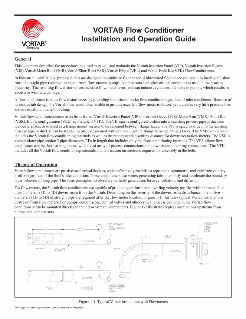
For flow meters, the Vortab flow conditioners are capable of producing uniform, non-swirling velocity profiles within three to fourpipe diameters (3D to 4D) downstream from the Vortab. Depending on the severity of the downstream disturbance, one to fivediameters (1D to 5D) of straight pipe are required after the flow meter location. Figure 1-1 illustrates typical Vortab installationsupstream from flow meters. For pumps, compressors, control valves and other critical process equipment, the Vortab flowconditioners can be mounted directly to their downstream components. Figure 1-2 illustrates typical installations upstream frompumps and compressors.
Figure 1-1. Typical Vortab Installation with Flowmeters
This document describes the procedures required to install, and maintain the Vortab Insertion Panel (VIP), Vortab Insertion Sleeve(VIS), Vortab Meter Run (VMR), Vortab Short Run (VSR), Vortab Elbow (VEL) and Vortab Field Kit (VFK) Flow Conditioners.
In Industrial installations, process plants are designed to minimize floor space. Abbreviated floor space can result in inadequate shortruns of straight pipe required upstream from flow meters, pumps, compressors and other critical components used in the processindustries. The resulting flow disturbances increase flow meter error, and can induce cavitation and noise in pumps, which results inexcessive wear and damage.
A flow conditioner isolates flow disturbances by providing a consistent outlet flow condition regardless of inlet conditions. Because ofits unique tab design, the Vortab flow conditioner is able to provide excellent flow meter isolation, yet it creates very little pressure lossand is virtually immune to fouling.
Vortab flow conditioners come in six basic forms: Vortab Insertion Panel (VIP), Insertion Sleeve (VIS), Meter Run (VMR), Short Run(VSR), Elbow configuration (VEL), or Field Kit (VFK). The VIP can be configured to slide into an existing process pipe or duct andwelded in place, or offered as a flange mount version to be captured between flange faces. The VIS is sized to slide into the existingprocess pipe or duct. It can be welded in place or secured with optional capture flange between flanges faces. The VMR spool pieceincludes the Vortab flow conditioning internals as well as the recommended settling distance for downstream flow meters. The VSR isa stand-alone pipe section 3 pipe diameters (3D) in length that includes only the flow conditioning internals. The VEL elbow flowconditioner can be short or long radius with a vast array of process connections and downstream metering connections. The VFKincludes all the Vortab flow conditioning internals and fabrication instructions required for assembly in the field.
VORTAB COMPANY FLOW CONDITIONER
This page is subject to proprietary rights statement on last page 2 Doc. No. 06EN003269 Rev. C
Figure 1-2. Typical Vortab Installation with Pumps/Compressors
FLOW CONDITIONER VORTAB COMPANY
This page is subject to proprietary rights statement on last page 3 Doc. No. 06EN003269 Rev. C
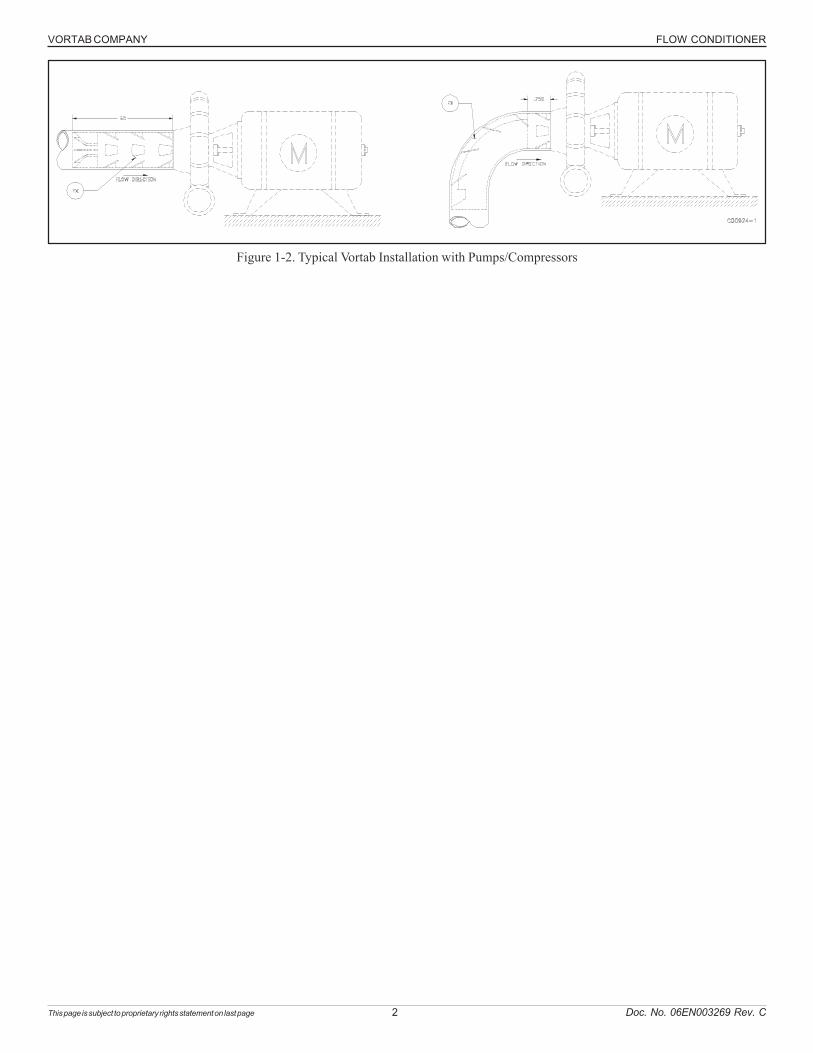
Technical Specifications
Vortab Insertion Sleeve (VIS)Process Pipe or Duct Inside DiameterCustomer specified inner diameterAvailable in sizes: .87 inch and higherAlso available in ¼, ½, and ¾ sch 40 sizes
Material of construction316L SST & Hastelloy C-276 for all sizesCarbon steel for sizes 4.51 inch and higher
Outside DiameterOutside diameter is undersized to fit the process pipe inside diameter
LengthApproximately 3 times the customer ID
Process ConnectionCapture flange or welded to the pipe orduct inside diameter
Vortab Meter Run (VMR)Pipe sizeAvailable in ¼, ½, and ¾ sch 401" (various schedules)2" and above all pipe schedules
Material of construction316L SST and Hastelloy C-276 throughout for all sizesCarbon steel 8 inch and aboveAlso available with 316L SST body and carbon steel flanges for allsizes
Length7 nominal pipe diameters (7D)Exception: Line sizes 2-inch and smaller, which may have longerlengths than 7D. Consult factory for specific lengths.
Process ConnectionButt weld preparation, male NPT, flanged or customer specified
Flow Element Connection For Flowmeter InstallationThreaded ¾,1, or 1-1/4 inch female NPT, 1-1/4 inch NPT, 1-1/2 inchflanged, or customer specified
Vortab Short Run (VSR)Pipe sizeAvailable in ¼, ½, and ¾ sch 401" (various schedules)2" and above all pipe schedules
Material of construction316L SST and Hastelloy C-276 throughout for all sizesCarbon steel 8 inch and aboveAlso available with 316L SST body and carbon steel flanges for all sizes
Length3 nominal pipe diameters (3D)
Process ConnectionButt weld preparation, male NPT, flanged or customer specified
Vortab Elbow (VEL)Pipe size1" and higherSmaller sizes available upon request
Material of construction316L SST, Hastelloy C-276, and carbon steel for all sizes
Elbow RadiusShort and Long radius
Process ConnectionButt weld preparation, male NPT, flanged or customer specified
Flow Element Connection For Flowmeter InstallationThreaded ¾,1, or 1-1/4 inch female NPT, 1-1/4 inch NPT, 1-1/2 inchflanged, or customer specified
Vortab Field Kit (VFK)Material of construction316L SST, Hastelloy C-276, and carbon steelOther materials available upon request
Process Pipe or Duct Inner DiameterCustomer specified
LengthApproximately 3 times the customer ID
Attachment MethodWelded in the field. Fabrication and welding instructions provided
Vortab Insertion Panel (VIP)Process Pipe or Duct Inside DiameterAvailable sizes: 2 inch to 40 inchAvailable in larger sizes (special)
Material of construction316L Stainless Steel
LengthTabs extend into downstream flow conduit a distance of.135 x conduit’s inner diameter.
Process ConnectionCapture Flange mounted or Weld-In-Place inside duct orpipe inner diameter.
VORTAB COMPANY FLOW CONDITIONER
This page is subject to proprietary rights statement on last page 4 Doc. No. 06EN003269 Rev. C
Installation - GeneralReceiving and Inspection
• Inspect for damage
• Packing List – verify correct configuration against purchase order. At a minimum, Vortab Company’s customer order number alongwith flow direction indicators will be etched on all products.
• If the above items are satisfactory then proceed with installation. If not, then STOP and contact the field representative or thefactory personnel for instructions.
There may be an additional sizing ring accompanying the Vortab Insertion Sleeve (VIS) in the shipping container. This is used toverify roundness and diameter during fabrication. It may be needed to facilitate installation in the following sections. The sizing ringcan be discarded upon completion of the VIS installation.
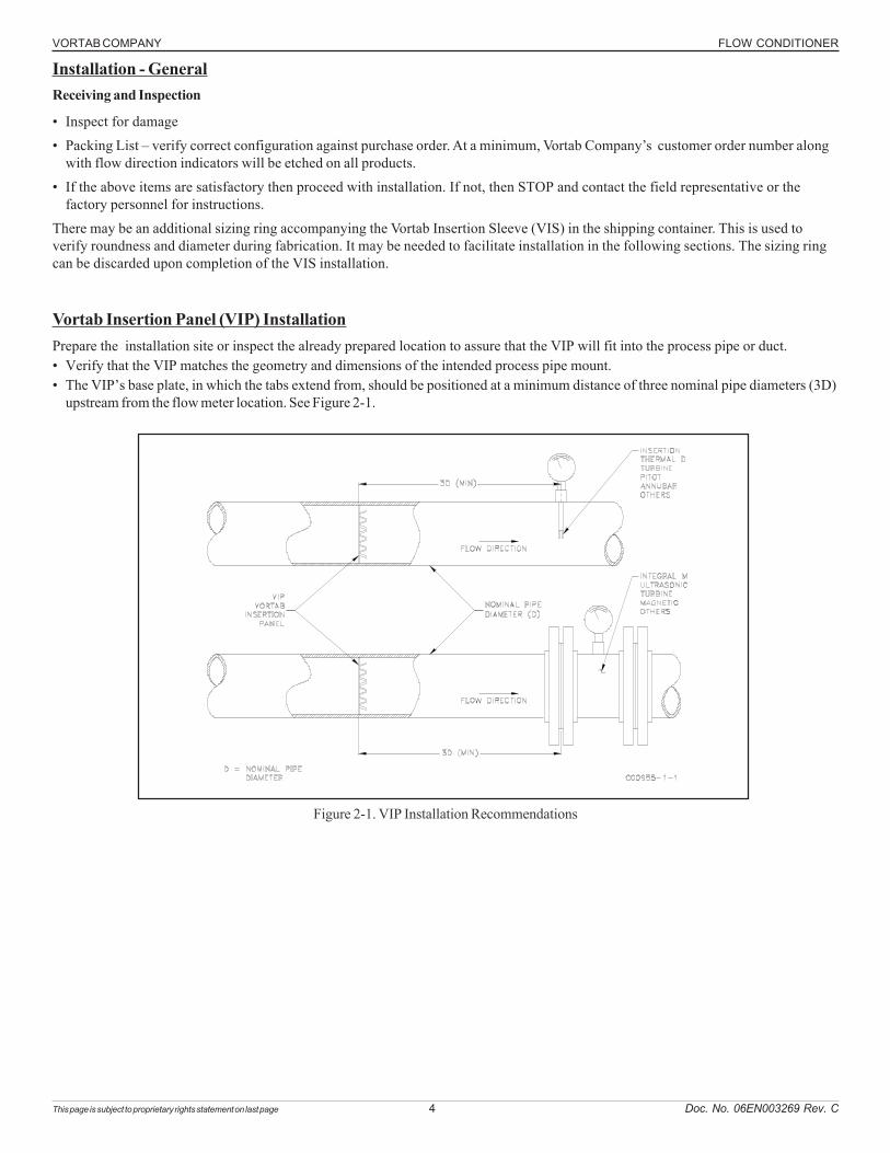
Vortab Insertion Panel (VIP) InstallationPrepare the installation site or inspect the already prepared location to assure that the VIP will fit into the process pipe or duct.• Verify that the VIP matches the geometry and dimensions of the intended process pipe mount.• The VIP’s base plate, in which the tabs extend from, should be positioned at a minimum distance of three nominal pipe diameters (3D)
upstream from the flow meter location. See Figure 2-1.
Figure 2-1. VIP Installation Recommendations
FLOW CONDITIONER VORTAB COMPANY
This page is subject to proprietary rights statement on last page 5 Doc. No. 06EN003269 Rev. C
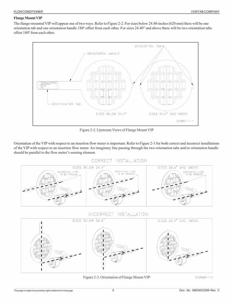
Flange Mount VIPThe flange-mounted VIP will appear one of two ways. Refer to Figure 2-2. For sizes below 24.40-inches (620 mm) there will be oneorientation tab and one orientation handle 180º offset from each other. For sizes 24.40" and above there will be two orientation tabsoffset 180º from each other.
Figure 2-2. Upstream Views of Flange Mount VIP
Orientation of the VIP with respect to an insertion flow meter is important. Refer to Figure 2-3 for both correct and incorrect installationsof the VIP with respect to an insertion flow meter. An imaginary line passing through the two orientation tabs and/or orientation handleshould be parallel to the flow meter’s sensing element.
Figure 2-3. Orientation of Flange Mount VIP
VORTAB COMPANY FLOW CONDITIONER
This page is subject to proprietary rights statement on last page 6 Doc. No. 06EN003269 Rev. C
When using the VIP upstream from flow meters other than FCI insert flow meters, whether it be in insert or flange mounted, such asturbine, annubar, and ultrasonic flow meters, orientation is not critical but should mimic that which was calibrated. The VIP should bepositioned upstream from the flow meter in the orientation and distance in which it was calibrated.
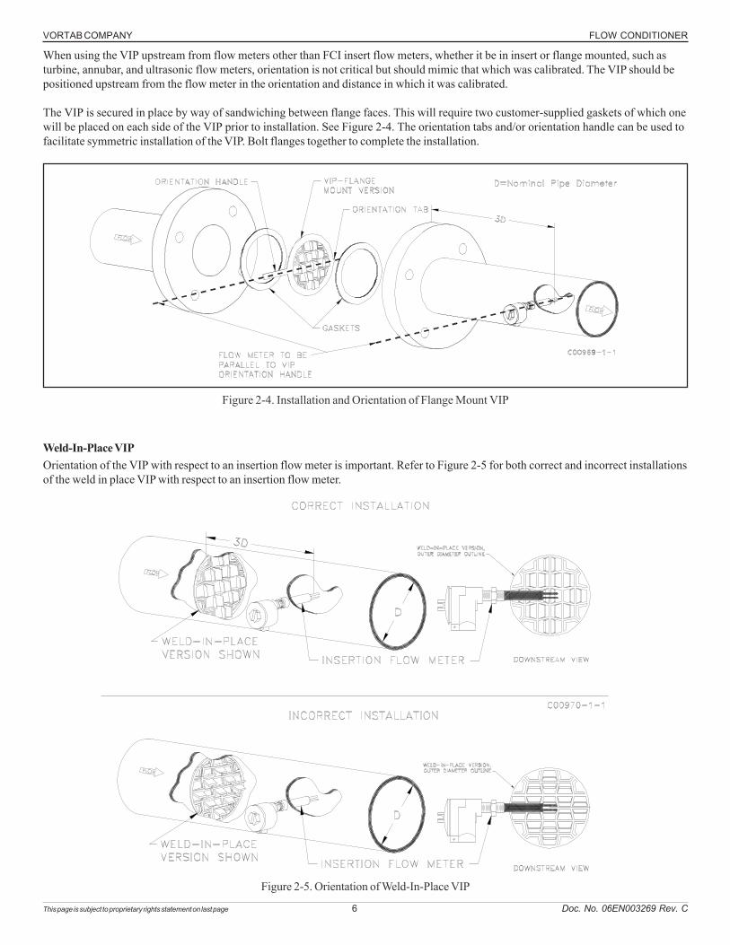
The VIP is secured in place by way of sandwiching between flange faces. This will require two customer-supplied gaskets of which onewill be placed on each side of the VIP prior to installation. See Figure 2-4. The orientation tabs and/or orientation handle can be used tofacilitate symmetric installation of the VIP. Bolt flanges together to complete the installation.
Figure 2-4. Installation and Orientation of Flange Mount VIP
Weld-In-Place VIPOrientation of the VIP with respect to an insertion flow meter is important. Refer to Figure 2-5 for both correct and incorrect installationsof the weld in place VIP with respect to an insertion flow meter.
Figure 2-5. Orientation of Weld-In-Place VIP
FLOW CONDITIONER VORTAB COMPANY
This page is subject to proprietary rights statement on last page 7 Doc. No. 06EN003269 Rev. C
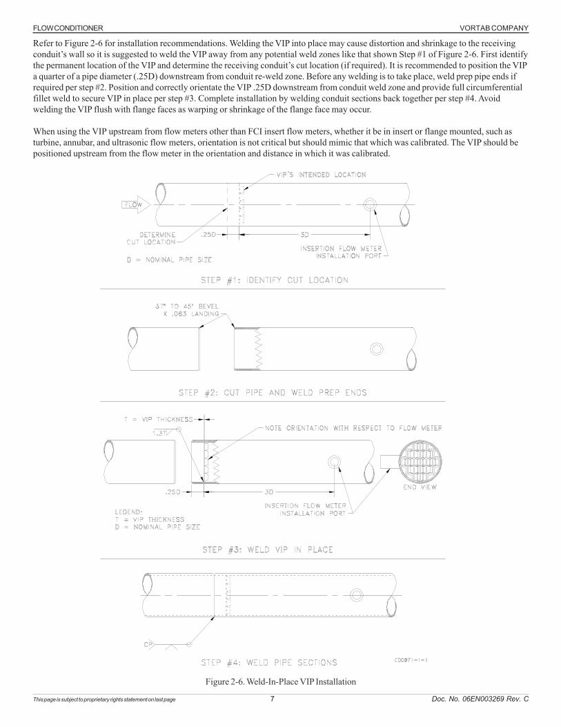
Refer to Figure 2-6 for installation recommendations. Welding the VIP into place may cause distortion and shrinkage to the receivingconduit’s wall so it is suggested to weld the VIP away from any potential weld zones like that shown Step #1 of Figure 2-6. First identifythe permanent location of the VIP and determine the receiving conduit’s cut location (if required). It is recommended to position the VIPa quarter of a pipe diameter (.25D) downstream from conduit re-weld zone. Before any welding is to take place, weld prep pipe ends ifrequired per step #2. Position and correctly orientate the VIP .25D downstream from conduit weld zone and provide full circumferentialfillet weld to secure VIP in place per step #3. Complete installation by welding conduit sections back together per step #4. Avoidwelding the VIP flush with flange faces as warping or shrinkage of the flange face may occur.
When using the VIP upstream from flow meters other than FCI insert flow meters, whether it be in insert or flange mounted, such asturbine, annubar, and ultrasonic flow meters, orientation is not critical but should mimic that which was calibrated. The VIP should bepositioned upstream from the flow meter in the orientation and distance in which it was calibrated.
Figure 2-6. Weld-In-Place VIP Installation
VORTAB COMPANY FLOW CONDITIONER
This page is subject to proprietary rights statement on last page 8 Doc. No. 06EN003269 Rev. C
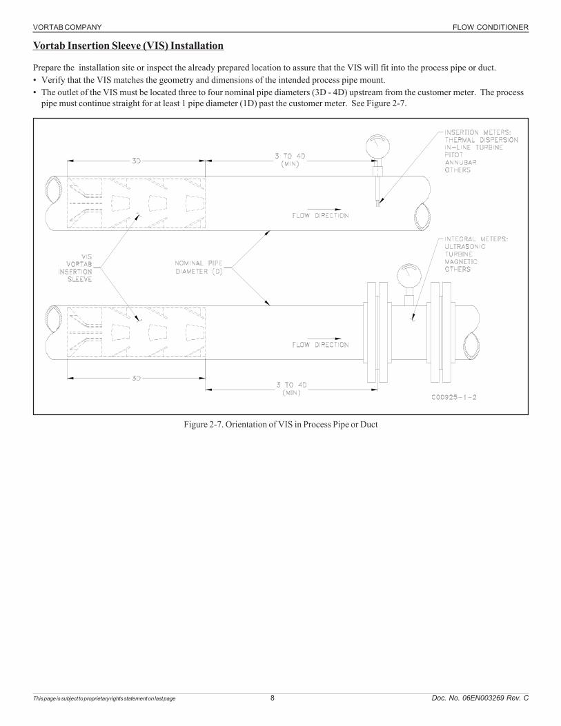
Figure 2-7. Orientation of VIS in Process Pipe or Duct
Vortab Insertion Sleeve (VIS) Installation
Prepare the installation site or inspect the already prepared location to assure that the VIS will fit into the process pipe or duct.• Verify that the VIS matches the geometry and dimensions of the intended process pipe mount.• The outlet of the VIS must be located three to four nominal pipe diameters (3D - 4D) upstream from the customer meter. The process
pipe must continue straight for at least 1 pipe diameter (1D) past the customer meter. See Figure 2-7.
FLOW CONDITIONER VORTAB COMPANY
This page is subject to proprietary rights statement on last page 9 Doc. No. 06EN003269 Rev. C
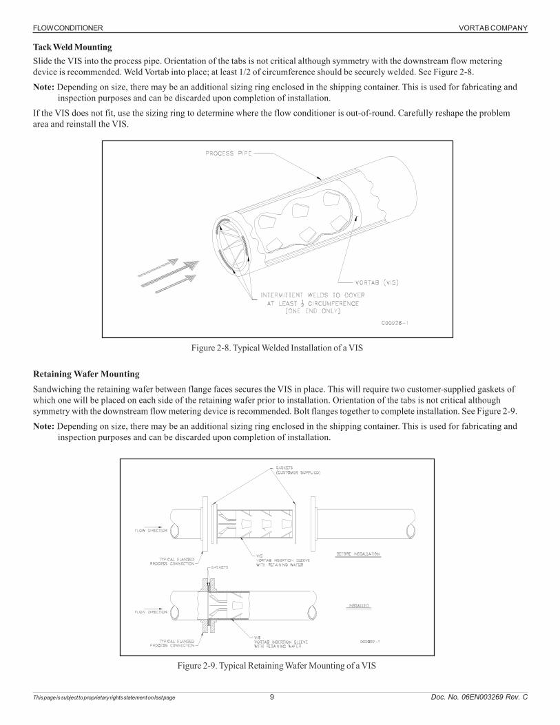
Tack Weld MountingSlide the VIS into the process pipe. Orientation of the tabs is not critical although symmetry with the downstream flow meteringdevice is recommended. Weld Vortab into place; at least 1/2 of circumference should be securely welded. See Figure 2-8.
Note: Depending on size, there may be an additional sizing ring enclosed in the shipping container. This is used for fabricating andinspection purposes and can be discarded upon completion of installation.
If the VIS does not fit, use the sizing ring to determine where the flow conditioner is out-of-round. Carefully reshape the problemarea and reinstall the VIS.
Figure 2-8. Typical Welded Installation of a VIS
Retaining Wafer MountingSandwiching the retaining wafer between flange faces secures the VIS in place. This will require two customer-supplied gaskets ofwhich one will be placed on each side of the retaining wafer prior to installation. Orientation of the tabs is not critical althoughsymmetry with the downstream flow metering device is recommended. Bolt flanges together to complete installation. See Figure 2-9.
Note: Depending on size, there may be an additional sizing ring enclosed in the shipping container. This is used for fabricating andinspection purposes and can be discarded upon completion of installation.
Figure 2-9. Typical Retaining Wafer Mounting of a VIS
VORTAB COMPANY FLOW CONDITIONER
This page is subject to proprietary rights statement on last page 10 Doc. No. 06EN003269 Rev. C
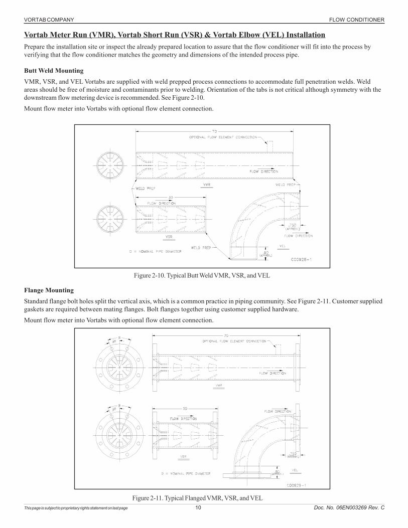
Vortab Meter Run (VMR), Vortab Short Run (VSR) & Vortab Elbow (VEL) InstallationPrepare the installation site or inspect the already prepared location to assure that the flow conditioner will fit into the process byverifying that the flow conditioner matches the geometry and dimensions of the intended process pipe.
Butt Weld MountingVMR, VSR, and VEL Vortabs are supplied with weld prepped process connections to accommodate full penetration welds. Weldareas should be free of moisture and contaminants prior to welding. Orientation of the tabs is not critical although symmetry with thedownstream flow metering device is recommended. See Figure 2-10.
Mount flow meter into Vortabs with optional flow element connection.
Figure 2-10. Typical Butt Weld VMR, VSR, and VEL
Flange MountingStandard flange bolt holes split the vertical axis, which is a common practice in piping community. See Figure 2-11. Customer suppliedgaskets are required between mating flanges. Bolt flanges together using customer supplied hardware.
Mount flow meter into Vortabs with optional flow element connection.
Figure 2-11. Typical Flanged VMR, VSR, and VEL
FLOW CONDITIONER VORTAB COMPANY
This page is subject to proprietary rights statement on last page 11 Doc. No. 06EN003269 Rev. C
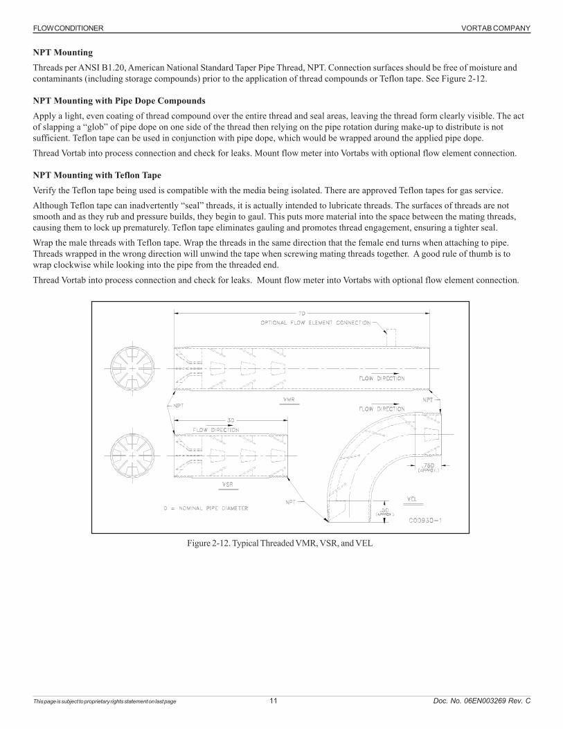
NPT MountingThreads per ANSI B1.20, American National Standard Taper Pipe Thread, NPT. Connection surfaces should be free of moisture andcontaminants (including storage compounds) prior to the application of thread compounds or Teflon tape. See Figure 2-12.
NPT Mounting with Pipe Dope CompoundsApply a light, even coating of thread compound over the entire thread and seal areas, leaving the thread form clearly visible. The actof slapping a “glob” of pipe dope on one side of the thread then relying on the pipe rotation during make-up to distribute is notsufficient. Teflon tape can be used in conjunction with pipe dope, which would be wrapped around the applied pipe dope.
Thread Vortab into process connection and check for leaks. Mount flow meter into Vortabs with optional flow element connection.
NPT Mounting with Teflon TapeVerify the Teflon tape being used is compatible with the media being isolated. There are approved Teflon tapes for gas service.
Although Teflon tape can inadvertently “seal” threads, it is actually intended to lubricate threads. The surfaces of threads are notsmooth and as they rub and pressure builds, they begin to gaul. This puts more material into the space between the mating threads,causing them to lock up prematurely. Teflon tape eliminates gauling and promotes thread engagement, ensuring a tighter seal.
Wrap the male threads with Teflon tape. Wrap the threads in the same direction that the female end turns when attaching to pipe.Threads wrapped in the wrong direction will unwind the tape when screwing mating threads together. A good rule of thumb is towrap clockwise while looking into the pipe from the threaded end.
Thread Vortab into process connection and check for leaks. Mount flow meter into Vortabs with optional flow element connection.
Figure 2-12. Typical Threaded VMR, VSR, and VEL
VORTAB COMPANY FLOW CONDITIONER
This page is subject to proprietary rights statement on last page 12 Doc. No. 06EN003269 Rev. C
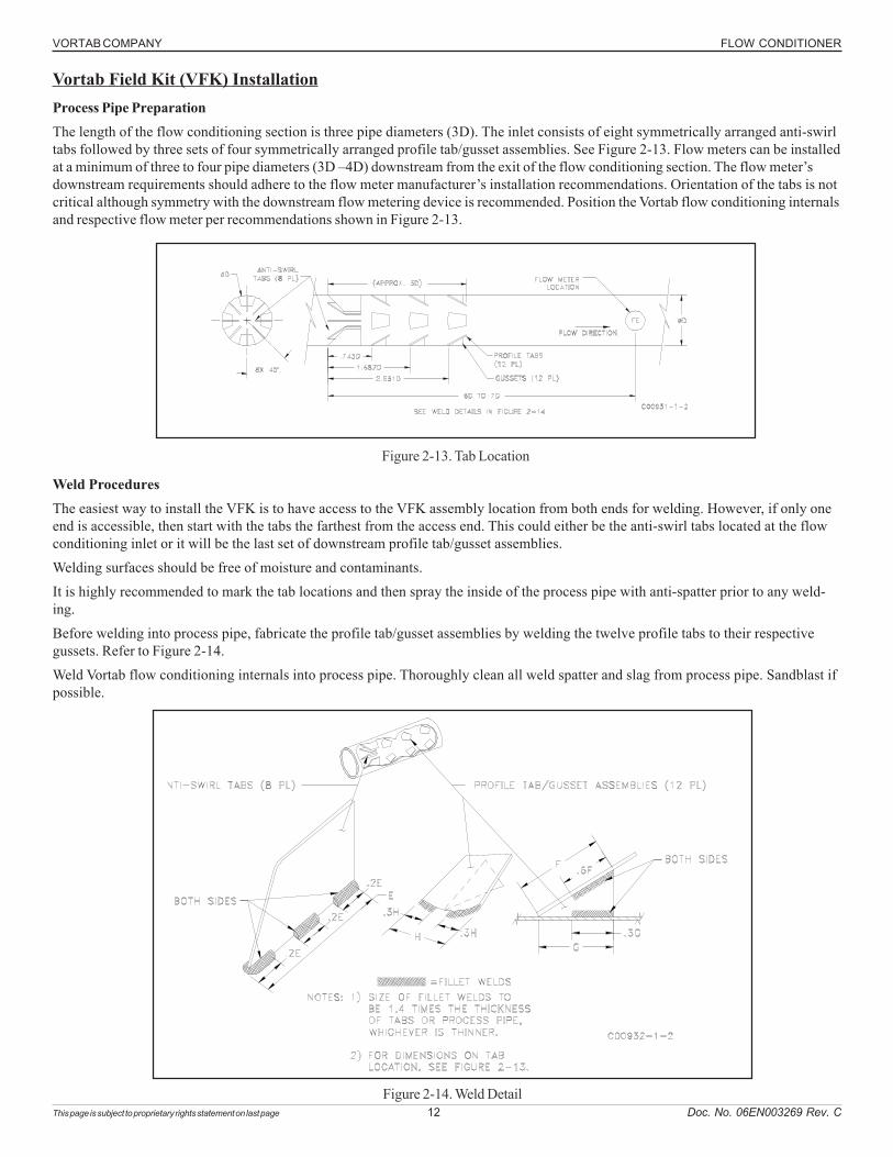
Vortab Field Kit (VFK) InstallationProcess Pipe PreparationThe length of the flow conditioning section is three pipe diameters (3D). The inlet consists of eight symmetrically arranged anti-swirltabs followed by three sets of four symmetrically arranged profile tab/gusset assemblies. See Figure 2-13. Flow meters can be installedat a minimum of three to four pipe diameters (3D –4D) downstream from the exit of the flow conditioning section. The flow meter’sdownstream requirements should adhere to the flow meter manufacturer’s installation recommendations. Orientation of the tabs is notcritical although symmetry with the downstream flow metering device is recommended. Position the Vortab flow conditioning internalsand respective flow meter per recommendations shown in Figure 2-13.
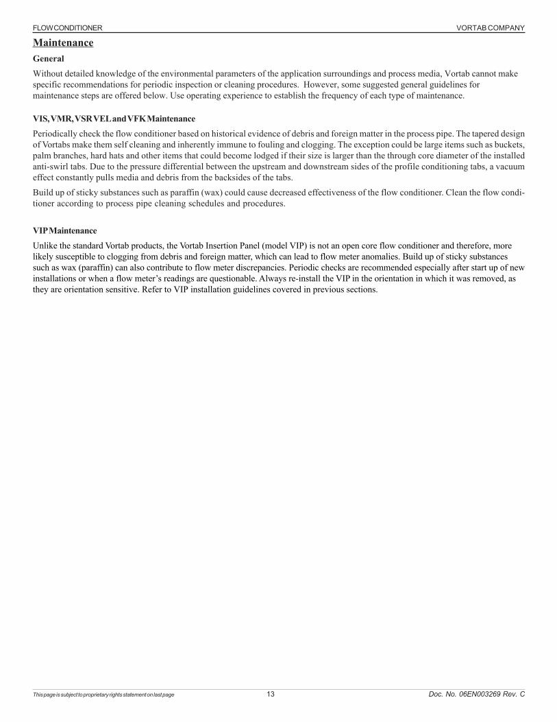
Figure 2-14. Weld Detail
Weld ProceduresThe easiest way to install the VFK is to have access to the VFK assembly location from both ends for welding. However, if only oneend is accessible, then start with the tabs the farthest from the access end. This could either be the anti-swirl tabs located at the flowconditioning inlet or it will be the last set of downstream profile tab/gusset assemblies.
Welding surfaces should be free of moisture and contaminants.
It is highly recommended to mark the tab locations and then spray the inside of the process pipe with anti-spatter prior to any weld-ing.
Before welding into process pipe, fabricate the profile tab/gusset assemblies by welding the twelve profile tabs to their respectivegussets. Refer to Figure 2-14.
Weld Vortab flow conditioning internals into process pipe. Thoroughly clean all weld spatter and slag from process pipe. Sandblast ifpossible.
Figure 2-13. Tab Location
FLOW CONDITIONER VORTAB COMPANY
This page is subject to proprietary rights statement on last page 13 Doc. No. 06EN003269 Rev. C
GeneralWithout detailed knowledge of the environmental parameters of the application surroundings and process media, Vortab cannot makespecific recommendations for periodic inspection or cleaning procedures. However, some suggested general guidelines formaintenance steps are offered below. Use operating experience to establish the frequency of each type of maintenance.
VIS, VMR, VSR VEL and VFK MaintenancePeriodically check the flow conditioner based on historical evidence of debris and foreign matter in the process pipe. The tapered designof Vortabs make them self cleaning and inherently immune to fouling and clogging. The exception could be large items such as buckets,palm branches, hard hats and other items that could become lodged if their size is larger than the through core diameter of the installedanti-swirl tabs. Due to the pressure differential between the upstream and downstream sides of the profile conditioning tabs, a vacuumeffect constantly pulls media and debris from the backsides of the tabs.
Build up of sticky substances such as paraffin (wax) could cause decreased effectiveness of the flow conditioner. Clean the flow condi-tioner according to process pipe cleaning schedules and procedures.
VIP MaintenanceUnlike the standard Vortab products, the Vortab Insertion Panel (model VIP) is not an open core flow conditioner and therefore, morelikely susceptible to clogging from debris and foreign matter, which can lead to flow meter anomalies. Build up of sticky substancessuch as wax (paraffin) can also contribute to flow meter discrepancies. Periodic checks are recommended especially after start up of newinstallations or when a flow meter’s readings are questionable. Always re-install the VIP in the orientation in which it was removed, asthey are orientation sensitive. Refer to VIP installation guidelines covered in previous sections.
Maintenance
VORTAB COMPANY FLOW CONDITIONER
This page is subject to proprietary rights statement on last page 14 Doc. No. 06EN003269 Rev. C
Customer Service and Technical Support
Vortab provides full in-house technical support for our products 7 a.m. to 5 p.m. PST, Monday through Friday (excepting holidays andan annual plant closure between Christmas and New Year's day). Also, additional technical representation is provided by Vortab fieldrepresentatives.
By MailVortab1755 La Costa Meadows Dr.San Marcos, CA 92078-5115 USAAttn: Customer Service Department
By PhoneContact the area Vortab regional representative. If a field representative is unable to be contacted or if a situation is unable to beresolved, contact the Vortab Customer Service Department toll free at 1 (800) 854-9959 or 1 (760) 736-6114.
By FaxTo describe problems in a graphical or pictorial manner, send a fax including a phone or fax number to the regional representative.Again, Vortab is available by facsimile if all possibilities have been exhausted with the authorized factory representative. Our Faxnumber is 1 (760) 736-6250; it is available 7 days a week, 24 hours a day.
By E-MailVortab Customer Service can be contacted by e-mail at: [email protected]. [email protected]. Describe the problem in detail making sure a telephone number and best time to be contacted isstated in the e-mail.
International SupportFor product information or product support outside the contiguous United States, Alaska, or Hawaii, contact your country’sVortab International Representative or the one nearest to you.
After Hours SupportFor product information visit Vortab's Worldwide Web at www.vortab.com. For product support call 1 (800) 854-9959 andfollow the prerecorded instructions. A person from the Technical Support Staff will be paged and promptly return the call.
Point of ContactThe point of contact for service, or return of items to Vortab is the authorized Vortab service representative.
Reference Documents• Return Authorization Request with Certificate of Non-Contamination• Warranty
Hardware Return Procedure
Complete a Return Authorization (RA) Request with Certificate of Non-Contamination form and mail or fax it to the Vortab CustomerService Department. After Vortab issues an RA number, complete the following steps.
1. Thoroughly clean the item to be returned.
2. Package each item with protective packing material similar to the original shipment cartons indicated below. All damageoccurring in transit is the customer’s responsibility.
a. Items weighing up to 60 pounds (27 kg) are to be boxed or crated in a manner which the contents will not shift or be externallydamaged in transit. Items weighing greater than 60 pounds (27 kg) or longer than four feet (1220 mm) should be secured inwooden crates.
b. Do not pack more than four items in each carton.
c. Packages weighing in excess of 70 pounds (32 kg) or with a combined length and girth of more than 138 inches (3500 mm)cannot be shipped by United Parcel Service. Larger packages or crates should be shipped by carriers who specialize in thetransport of heavy pipe.
d. The RA number should be noted on the packing list and marked clearly on the outside of the box or crate.
3. Prepay freight to the Vortab receiving door.
FLOW CONDITIONER VORTAB COMPANY
This page is subject to proprietary rights statement on last page 15 Doc. No. 06EN003269 Rev. C
Shipping and Handling Charges
All Shipping (Warranty/Nonwarranty Repairs or Returns)
The customer prepays all shipping, freight, duty/entry and handling charges from the customer site to the Vortab door. If the customerdoes not prepay, Vortab will invoice the customer for the charges that appear on the freight bill. Address the return equipment to:
VORTAB1755 LA COSTA MEADOWS DRIVESAN MARCOS, CA. 92078-5115 USAATTN: REPAIR DEPT.RA NUMBER:
Warranty Repairs or ReturnsVortab prepays ground transportation charges for return of freight to the customer’s door. Vortab reserves the right to returnequipment by the carrier of our choice.International freight, handling charges, duty/entry fees for return of equipment are paid by the customer.
Non-Warranty Repairs or ReturnsVortab returns repaired equipment to the customer either collect or prepaid and adds freight charges to the customer invoice.
Return to Stock EquipmentThe customer is responsible for all shipping and freight charges for equipment that is returned to Vortab stock from the customer site. These items will not be credited to customer’s account until either all freight charges are cleared or until the customer agrees to haveany freight costs incurred by Vortab deducted, along with applicable return to stock charges, from the credit invoice. Exceptions aremade for duplicate shipments made by Vortab.If any repair or return equipment is received at Vortab, freight collect, without prior factory consent, Vortab bills the sender for thesecharges.
Field Service ProceduresContact your Vortab field representative to request field service.A field service technician is dispatched to the site from either the Vortab factory or one of the Vortab representative offices. After thework is complete, the technician completes a preliminary field service report at the customer site and leaves a copy with the customer.Following the service call, the technician completes a formal, detailed service report. The formal report is mailed to the customerwithin five days of the technician’s return to the factory or office.
Field Service RatesAll field service calls are billed at the prevailing rates as listed in the Vortab Price Book unless specifically excepted by the VortabCustomer Service Manager. Vortab reserves the right to bill for travel times at Vortab’s discretion.Customers are charged for shipping costs related to the transfer of equipment to and from the job site. They are also invoiced for fieldservice work and travel expenses by Vortab’s Accounting Department.

VORTAB COMPANY FLOW CONDITIONER
This page is subject to proprietary rights statement on last page 16 Doc. No. 06EN003269 Rev. C
INTENTIONALLY LEFT BLANK
FLOW CONDITIONER VORTAB COMPANY
This page is subject to proprietary rights statement on last page 17 Doc. No. 06EN003269 Rev. C
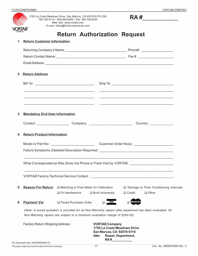
1. Return Customer Information
Returning Company’s Name:__________________________________ Phone# __________________
Return Contact Name: ______________________________________ Fax # ____________________
Email Address: _______________________________________________________________________
2. Return Address
Bill To: _________________________________ Ship To: __________________________________
_______________________________________ _________________________________________
_______________________________________ _________________________________________
_______________________________________ _________________________________________
3. Mandatory End User Information
Contact: __________________ Company: ________________________ Country: _____________
4. Return Product Information
Model or Part No: ________________________ Customer Order No(s): ______________________
Failure Symptoms (Detailed Description Required): _________________________________________
___________________________________________________________________________________
What Correspondence Was Done Via Phone or Field Visit by VORTAB: ________________________
___________________________________________________________________________________
VORTAB Factory Technical Service Contact: ______________________________________________
5. Reason For Return Matching to Flow Meter for Calibration Damage to Flow Conditioning Internals
Fit Interference Built Incorrectly Credit Other
6. Payment Via Faxed Purchase Order
(Note: A priced quotation is provided for all Non-Warranty repairs after equipment has been evaluated. All
Non-Warranty repairs are subject to a minimum evaluation charge of $250.00)
Factory Return Shipping Address: VORTAB Company1755 La Costa Meadows DriveSan Marcos, CA 92078-5115Attn: Repair Department,
RA #____________FCI Document No. 05CS000004D [V]
Return Authorization Request
1755 La Costa Meadows Drive, San Marcos, CA 92078-5115 USA760-736-6114 / 800-854-9959 / Fax 760-736-6250
Web Site: www.vortab.comE-mail: [email protected]
RA #___________
VORTAB COMPANY FLOW CONDITIONER
This page is subject to proprietary rights statement on last page 18 Doc. No. 06EN003269 Rev. C
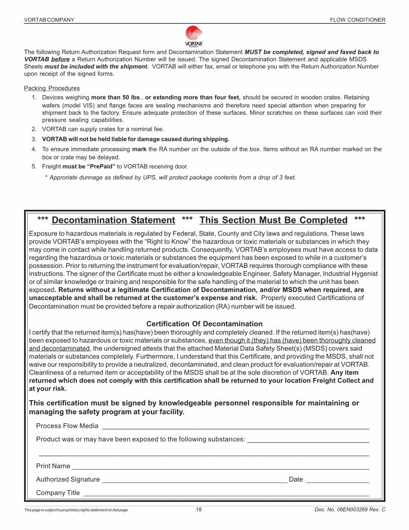
The following Return Authorization Request form and Decontamination Statement MUST be completed, signed and faxed back toVORTAB before a Return Authorization Number will be issued. The signed Decontamination Statement and applicable MSDSSheets must be included with the shipment. VORTAB will either fax, email or telephone you with the Return Authorization Numberupon receipt of the signed forms.
Packing Procedures1. Devices weighing more than 50 lbs., or extending more than four feet, should be secured in wooden crates. Retaining
wafers (model VIS) and flange faces are sealing mechanisms and therefore need special attention when preparing forshipment back to the factory. Ensure adequate protection of these surfaces. Minor scratches on these surfaces can void theirpressure sealing capabilities.
2. VORTAB can supply crates for a nominal fee.
3. VORTAB will not be held liable for damage caused during shipping.4. To ensure immediate processing mark the RA number on the outside of the box. Items without an RA number marked on the
box or crate may be delayed.5. Freight must be “PrePaid” to VORTAB receiving door.
* Approriate dunnage as defined by UPS, will protect package contents from a drop of 3 feet.
*** Decontamination Statement *** This Section Must Be Completed ***
Process Flow Media ________________________________________________________________________
Product was or may have been exposed to the following substances: _________________________________
_________________________________________________________________________________________
Print Name ________________________________________________________________________________
Authorized Signature __________________________________________________ Date _________________
Company Title _____________________________________________________________________________
Exposure to hazardous materials is regulated by Federal, State, County and City laws and regulations. These lawsprovide VORTAB’s employees with the “Right to Know” the hazardous or toxic materials or substances in which theymay come in contact while handling returned products. Consequently, VORTAB’s employees must have access to dataregarding the hazardous or toxic materials or substances the equipment has been exposed to while in a customer’spossession. Prior to returning the instrument for evaluation/repair, VORTAB requires thorough compliance with theseinstructions. The signer of the Certificate must be either a knowledgeable Engineer, Safety Manager, Industrial Hygenistor of similar knowledge or training and responsible for the safe handling of the material to which the unit has beenexposed. Returns without a legitimate Certification of Decontamination, and/or MSDS when required, areunacceptable and shall be returned at the customer’s expense and risk. Properly executed Certifications ofDecontamination must be provided before a repair authorization (RA) number will be issued.
Certification Of DecontaminationI certify that the returned item(s) has(have) been thoroughly and completely cleaned. If the returned item(s) has(have)been exposed to hazardous or toxic materials or substances, even though it (they) has (have) been thoroughly cleanedand decontaminated, the undersigned attests that the attached Material Data Safety Sheet(s) (MSDS) covers saidmaterials or substances completely. Furthermore, I understand that this Certificate, and providing the MSDS, shall notwaive our responsibility to provide a neutralized, decontaminated, and clean product for evaluation/repair at VORTAB.Cleanliness of a returned item or acceptability of the MSDS shall be at the sole discretion of VORTAB. Any itemreturned which does not comply with this certification shall be returned to your location Freight Collect andat your risk.
This certification must be signed by knowledgeable personnel responsible for maintaining ormanaging the safety program at your facility.
FLOW CONDITIONER VORTAB COMPANY
This page is subject to proprietary rights statement on last page 19 Doc. No. 06EN003269 Rev. C
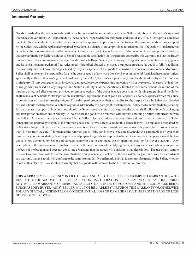
Goods furnished by the Seller are to be within the limits and of the sizes published by the Seller and subject to the Seller’s standardtolerances for variations. All items made by the Seller are inspected before shipment, and should any of said items prove defectivedue to faults in manufacture or performance under Seller approved applications, or fail to meet the written specifications acceptedby the Seller, they will be replaced or repaired by Seller at no charge to Buyer provided return or notice of rejection of such materialis made within a reasonable period but in no event longer than one (1) year from date of shipment to Buyer, and provided further,that an examination by Seller discloses to Seller’s reasonable satisfaction that the defect is covered by this warranty and that the Buyerhas not returned the equipment in a damaged condition due to Buyer’s or Buyer’s employees’, agents’, or representatives’ negligenceand Buyer has not tampered, modified, redesigned, misapplied, abused, or misused the goods as to cause the goods to fail. In addition,this warranty shall not cover damage caused by Buyer’s exposure of the goods to corrosive or abrasive environments. Moreover,Seller shall in no event be responsible for (1) the cost or repair of any work done by Buyer on material furnished hereunder (unlessspecifically authorized in writing in each instance by Seller), (2) the cost or repair of any modifications added by a Distributor ora third party, (3) any consequential or incidental damages, losses, or expenses in connection with or by reason of the use of or inabilityto use goods purchased for any purpose, and Seller’s liability shall be specifically limited to free replacement, or refund of thepurchase price, at Seller’s option, provided return or rejection of the goods is made consistent with this paragraph, and the Sellershall in no event be liable for transportation, installation, adjustment, loss of good will or profits, or other expenses which may arisein connection with such returned goods, or (4) the design of products or their suitability for the purpose for which they are intendedor used. Should the Buyer receive defective goods as defined by this paragraph, the Buyer shall notify the Seller immediately, statingfull particulars in support of his claim, and should the Seller agree to a return of the goods, the Buyer shall follow Seller’s packagingand transportation directions explicitly. In no case are the goods to be returned without first obtaining a return authorization fromthe Seller. Any repair or replacement shall be at Seller’s factory, unless otherwise directed, and shall be returned to Sellertransportation prepaid by Buyer. If the returned goods shall prove defective under this clause they will be replaced or repaired bySeller at no charge to Buyer provided the return or rejection of such material is made within a reasonable period, but in no event longerthan (1) year from the date of shipment of the returned goods. If the goods prove to be defective under this paragraph, the Buyer shallremove the goods immediately from the process and prepare the goods for shipment to Seller. Continued use or operation of defectivegoods is not warranted by Seller and damage occurring due to continued use or operation shall be for Buyer’s account. Anydescription of the goods contained in this offer is for the sole purpose of identifying them, and any such description is not part ofthe basis of the bargain, and does not constitute a warranty that the goods will conform to that description. The use of any sampleor model in connection with this offer is for illustrative purposes only, is not part of the basis of the bargain, and is not to be construedas a warranty that the goods will conform to the sample or model. No affirmation of that fact or promise made by the Seller, whetheror not in this offer, will constitute a warranty that the goods will conform to the affirmation or promise.
THIS WARRANTY IS EXPRESSLY IN LIEU OF ANY AND ALL OTHER EXPRESS OR IMPLIED WARRANTIES WITHRESPECT TO THE GOODS OR THEIR INSTALLATION, USE, OPERATION, REPLACEMENT OR REPAIR, INCLUDINGANY IMPLIED WARRANTY OF MERCHANTABILITY OR FITNESS OF PURPOSE; AND THE GOODS ARE BEINGPURCHASED BY BUYER “AS IS”. SELLER WILL NOT BE LIABLE BY VIRTUE OF THIS WARRANTY OR OTHERWISEFOR ANY SPECIAL, INCIDENTAL OR CONSEQUENTIAL LOSS OR DAMAGE RESULTING FROM THE USE OR LOSSOF USE OF THE GOODS.
Instrument Warranty
FLOW CONDITIONER VORTAB COMPANY
Doc. No. 06EN003269 Rev. CVORTAB All Rights Reserved
Notice of Proprietary RightsThis document contains confidential technical data, including trade secrets and proprietary information which is the property of Vortab and protected byUnited States Patent Numbers 4,929,088 and 4,981,368. Disclosure of this data to you is expressly conditioned upon your assent that its use is limitedto use within your company only (and does not include manufacture or processing uses). Any other use is strictly prohibited without the prior written consentof Vortab.
Visit FCI on the Worldwide Web: www.vortab.com 1755 La Costa Meadows Drive, San Marcos, California 92078 USA - 760-736-6114 - 800-854-9959 - Fax 760-736-6250