Embed Size (px)
Citation preview
Remote Automation Solutions
Form A6255 Part Number D301454X012 March 2008
Annubar Flow Calculation Software (for FloBoss™ 107 Flow Managers) User Manual
Annubar Flow Calculation Software User Manual
ii Rev. Mar-08
Revision Tracking Sheet
March 2008
This manual may be revised periodically to incorporate new or updated information. The revision date of each page appears at the bottom of the page opposite the page number. A change in revision date to any page also changes the date of the manual that appears on the front cover. Listed below is the revision date of each page (if applicable):
Page Revision All pages Mar-08 Initial release Feb-08
NOTICE Remote Automation Solutions (“RAS”), division of Emerson Process Management shall not be liable for technical or editorial errors in this manual or omissions from this manual. RAS MAKES NO WARRANTIES, EXPRESSED OR IMPLIED, INCLUDING THE IMPLIED WARRANTIES OF MERCHANTABILITY AND FITNESS FOR A PARTICULAR PURPOSE WITH RESPECT TO THIS MANUAL AND, IN NO EVENT SHALL RAS BE LIABLE FOR ANY INCIDENTAL, PUNITIVE, SPECIAL OR CONSEQUENTIAL DAMAGES INCLUDING, BUT NOT LIMITED TO, LOSS OF PRODUCTION, LOSS OF PROFITS, LOSS OF REVENUE OR USE AND COSTS INCURRED INCLUDING WITHOUT LIMITATION FOR CAPITAL, FUEL AND POWER, AND CLAIMS OF THIRD PARTIES.
Bristol, Inc., Bristol Babcock Ltd, Bristol Canada, BBI SA de CV and the Flow Computer Division are wholly owned subsidiaries of Emerson Electric Co. doing business as Remote Automation Solutions (“RAS”), a division of Emerson Process Management. FloBoss, ROCLINK, Bristol, Bristol Babcock, ControlWave, TeleFlow and Helicoid are trademarks of RAS. AMS, PlantWeb and the PlantWeb logo are marks of Emerson Electric Co. The Emerson logo is a trademark and service mark of the Emerson Electric Co. All other trademarks are property of their respective owners.
The contents of this publication are presented for informational purposes only. While every effort has been made to ensure informational accuracy, they are not to be construed as warranties or guarantees, express or implied, regarding the products or services described herein or their use or applicability. RAS reserves the right to modify or improve the designs or specifications of such products at any time without notice. All sales are governed by RAS’ terms and conditions which are available upon request.
RAS does not assume responsibility for the selection, use or maintenance of any product. Responsibility for proper selection, use and maintenance of any RAS product remains solely with the purchaser and end-user.
©2008 Remote Automation Solutions, division of Emerson Process Management. All rights reserved.
Annubar Flow Calculation Software User Manual
Rev. Mar-08 iii
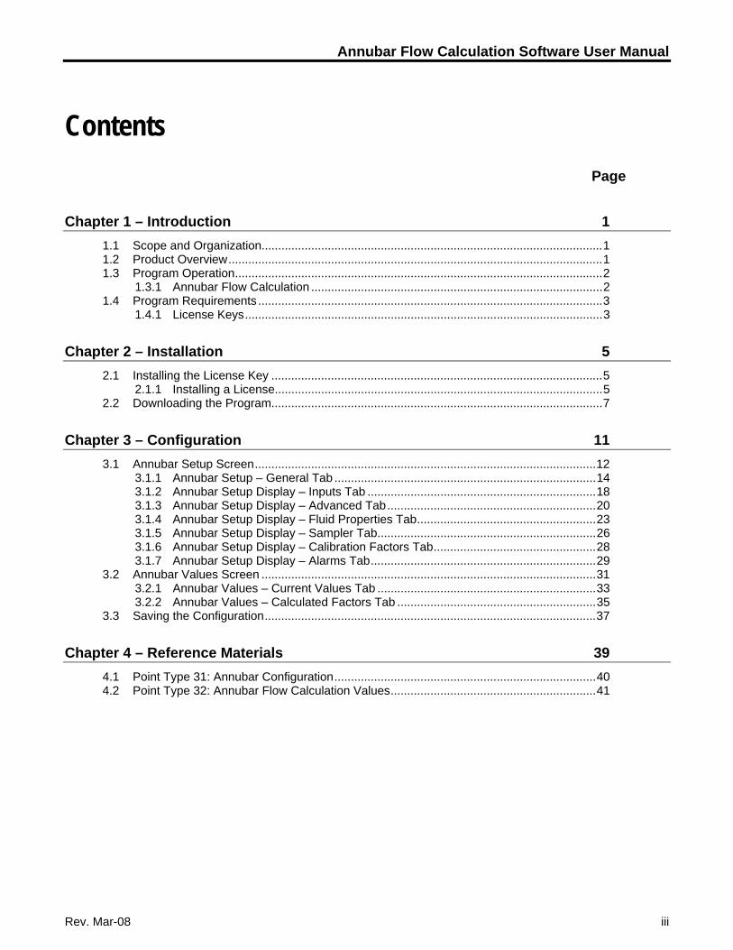
Contents
Page
Chapter 1 – Introduction 1 1.1 Scope and Organization.......................................................................................................1 1.2 Product Overview.................................................................................................................1 1.3 Program Operation...............................................................................................................2
1.3.1 Annubar Flow Calculation ........................................................................................2 1.4 Program Requirements ........................................................................................................3
1.4.1 License Keys............................................................................................................3
Chapter 2 – Installation 5 2.1 Installing the License Key ....................................................................................................5
2.1.1 Installing a License...................................................................................................5 2.2 Downloading the Program....................................................................................................7
Chapter 3 – Configuration 11 3.1 Annubar Setup Screen.......................................................................................................12
3.1.1 Annubar Setup – General Tab ...............................................................................14 3.1.2 Annubar Setup Display – Inputs Tab .....................................................................18 3.1.3 Annubar Setup Display – Advanced Tab...............................................................20 3.1.4 Annubar Setup Display – Fluid Properties Tab......................................................23 3.1.5 Annubar Setup Display – Sampler Tab..................................................................26 3.1.6 Annubar Setup Display – Calibration Factors Tab.................................................28 3.1.7 Annubar Setup Display – Alarms Tab....................................................................29
3.2 Annubar Values Screen .....................................................................................................31 3.2.1 Annubar Values – Current Values Tab ..................................................................33 3.2.2 Annubar Values – Calculated Factors Tab ............................................................35
3.3 Saving the Configuration....................................................................................................37
Chapter 4 – Reference Materials 39 4.1 Point Type 31: Annubar Configuration...............................................................................40 4.2 Point Type 32: Annubar Flow Calculation Values..............................................................41

Annubar Flow Calculation Software User Manual
iv Rev. Mar-08
[This page is intentionally left blank.]
Annubar Flow Calculation Software User Manual
Rev. Mar-08 1
Chapter 1 – Introduction
This chapter describes the structure of this manual and presents an overview of the Annubar Flow Calculation Software for the FloBoss™ 107.
1.1 Scope and Organization This document serves as the user manual for the Annubar Flow Calculation Software, which is intended for use in a FloBoss 107 (FB107). This manual describes how to download, install, and configure the Annubar Flow Calculation user program (referred to as the “Annubar program” or “the program” throughout the rest of this manual). You access and configure this program using ROCLINK™ 800 Configuration Software loaded on an IBM-compatible personal computer running Windows® 98, NT 4.0 (with Service Pack 6), 2000 (with Service Pack 2), or XP.
The sections in this manual provide information in a sequence appropriate for first-time users. Once you become familiar with the procedures and the software, the manual becomes a reference tool.
This manual has the following major sections:
Chapter 1 – Introduction Chapter 2 – Installation Chapter 3 – Configuration Chapter 4 – Reference
This manual assumes that you are familiar with the FB107 and its configuration. For more information, refer to the FloBoss 107 Flow Manager Instruction Manual (Form A6206) or the ROCLINK 800 Configuration Software User Manual (for FloBoss 107) (Form A6217).
1.2 Product Overview The Annubar program allows a FB107 to calculate flow rates, integrate volumes, and archive historical values for installations implementing an Annubar end element. The program supports both the Annubar Diamond II and Annubar 485 “T-shaped” element types. The program provides flow calculations for gas, steam/water and fluid applications in either Metric or Imperial units.
The Annubar Flow Calculation Program is compatible with FB107, firmware version 1.10 and greater. The user program is downloaded and configured in the FB107 with ROCLINK™ 800 Configuration Software (version 1.75 or greater).
Annubar Flow Calculation Software User Manual
2 Rev. Mar-08
The components of the Annubar Flow Calculation Software are:
The Annubar Flow Calculation user program that loads into FloBoss memory to provide support for Annubar applications.
License Key, containing license(s) enabling the Annubar user program.
This manual, Form A6255.
1.3 Program Operation The FB107 reads flow inputs (differential pressure, temperature, and static pressure) once every second. The Annubar instantaneous flow rate calculation is performed once a second by the user program. Configuration is accomplished through a custom Annubar Setup user display.
The program itself does not perform gas or fluid property calculations. Gas properties can be obtained from FloBoss firmware, using AGA8 1992 standards or from a separate user program installed in the FloBoss. The program requires density at base conditions, density at flowing conditions, and heating value be provided.
The user program calculates instantaneous volume, mass and energy and provides the rates to the FB107 for archival into the periodic and daily databases. Values saved to the historical database are in the units shown below.
Volume Units Mass Units Energy Units
MCF or km3 Mlb or Tonnes MMBTU or GJoules
1.3.1 Annubar Flow Calculation
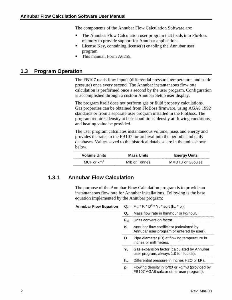
The purpose of the Annubar Flow Calculation program is to provide an instantaneous flow rate for Annubar installations. Following is the base equation implemented by the Annubar program:
Annubar Flow Equation Qm = Fna * K * D2 * Ya * sqrt (hw * pf).
Qm Mass flow rate in lbm/hour or kg/hour.
Fna Units conversion factor.
K Annubar flow coefficient (calculated by Annubar user program or entered by user).
D Pipe diameter (ID) at flowing temperature in inches or millimeters.
Ya Gas expansion factor (calculated by Annubar user program, always 1.0 for liquids).
hw Differential pressure in Inches H2O or kPa.
pf Flowing density in lb/ft3 or kg/m3 (provided by FB107 AGA8 calc or other user program).
Annubar Flow Calculation Software User Manual
Rev. Mar-08 3
1.4 Program Requirements
The Annubar program is compatible with version 1.10 (or greater) of the FB107 firmware and with version 1.75 (or greater) of the ROCLINK 800 software.
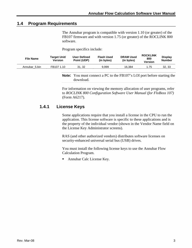
Program specifics include:
File Name Target Unit/ Version
User Defined Point (UDP)
Flash Used (in bytes)
DRAM Used (in bytes)
ROCKLINK 800
Version Display Number
Annubar_5.bin FB107 1.10 31, 32 9,999 16,384 1.75 32, 33
Note: You must connect a PC to the FB107’s LOI port before starting the download.
For information on viewing the memory allocation of user programs, refer to ROCLINK 800 Configuration Software User Manual (for FloBoss 107) (Form A6217).
1.4.1 License Keys
Some applications require that you install a license in the CPU to run the application. This license software is specific to these applications and is the property of the individual vendor (shown in the Vendor Name field on the License Key Administrator screens).
RAS (and other authorized vendors) distributes software licenses on security-enhanced universal serial bus (USB) drives.
You must install the following license keys to use the Annubar Flow Calculation Program.
Annubar Calc License Key.

Annubar Flow Calculation Software User Manual
4 Rev. Mar-08
[This page is intentionally left blank.]
Annubar Flow Calculation Software User Manual
Chapter 2 – Installation
This section provides instructions for installing the Annubar program. Read Section 1.4 of this manual for program requirements.
Note: The program and license key can be installed in any order. The manual shows the installation of the license key first.
2.1 Installing the License Key
A license key is required to use the Annubar program. The license is a USB key-based license. Section 2.1.1 describes the installation process.
2.1.1 Installing a License
To install a USB key-based license on the FB107:
1. Insert the USB license key in a USB port on your PC.
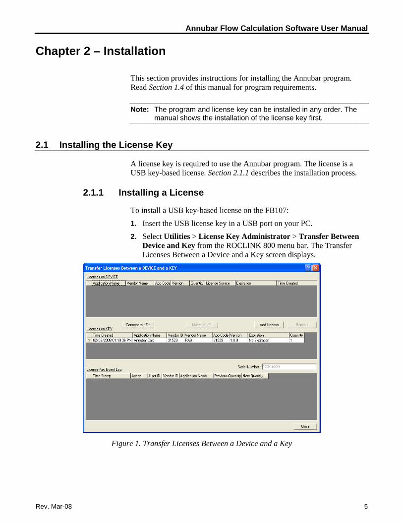
2. Select Utilities > License Key Administrator > Transfer Between Device and Key from the ROCLINK 800 menu bar. The Transfer Licenses Between a Device and a Key screen displays.
Figure 1. Transfer Licenses Between a Device and a Key
Rev. Mar-08 5
Annubar Flow Calculation Software User Manual
Note: This screen has three sections. The upper portion (Licenses on Device) shows any software licenses installed on the FB107. The middle portion (Licenses on Key) shows software licenses on the license key. The lower portion of the screen (License Key Event Log) provides a rolling log of the last eight events related to this license key.
3. Select the key-based license you want to transfer to the FB107 (Annubar Calc, as shown in Figure 1).
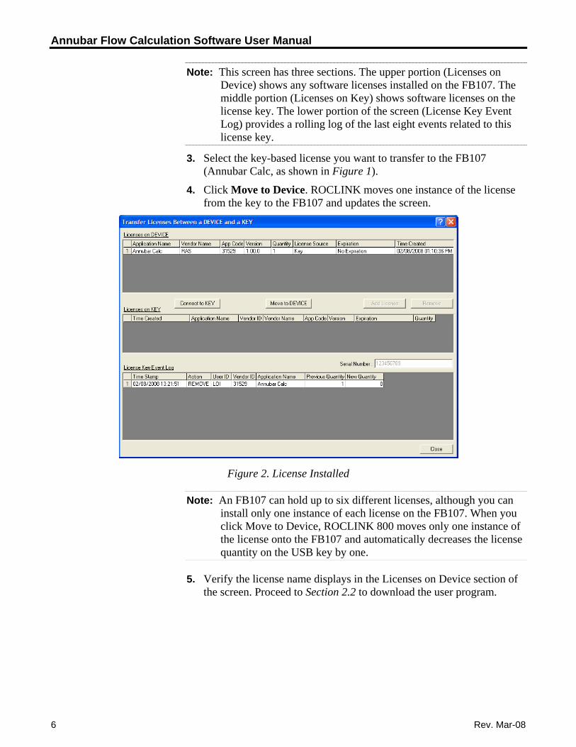
4. Click Move to Device. ROCLINK moves one instance of the license from the key to the FB107 and updates the screen.
Figure 2. License Installed
Note: An FB107 can hold up to six different licenses, although you can install only one instance of each license on the FB107. When you click Move to Device, ROCLINK 800 moves only one instance of the license onto the FB107 and automatically decreases the license quantity on the USB key by one.
5. Verify the license name displays in the Licenses on Device section of the screen. Proceed to Section 2.2 to download the user program.
6 Rev. Mar-08
Annubar Flow Calculation Software User Manual
2.2 Downloading the Program
This section provides instructions for installing the program into the Flash memory on the FB107.
To download the program using ROCLINK 800 software:
1. Connect the FB107 to your computer using the LOI port.
2. Start and logon to ROCLINK 800.
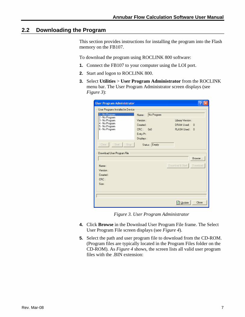
3. Select Utilities > User Program Administrator from the ROCLINK menu bar. The User Program Administrator screen displays (see Figure 3):
Figure 3. User Program Administrator
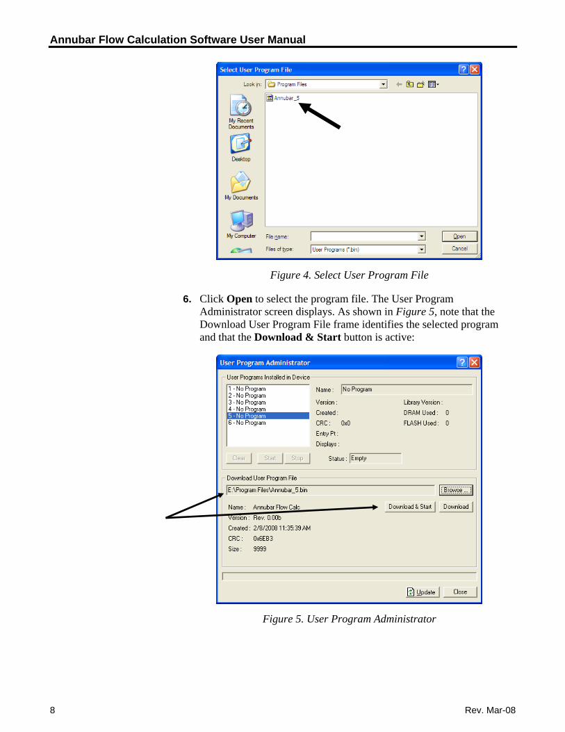
4. Click Browse in the Download User Program File frame. The Select User Program File screen displays (see Figure 4).
5. Select the path and user program file to download from the CD-ROM. (Program files are typically located in the Program Files folder on the CD-ROM). As Figure 4 shows, the screen lists all valid user program files with the .BIN extension:
Rev. Mar-08 7
Annubar Flow Calculation Software User Manual
Figure 4. Select User Program File
6. Click Open to select the program file. The User Program Administrator screen displays. As shown in Figure 5, note that the Download User Program File frame identifies the selected program and that the Download & Start button is active:
Figure 5. User Program Administrator
8 Rev. Mar-08
Annubar Flow Calculation Software User Manual
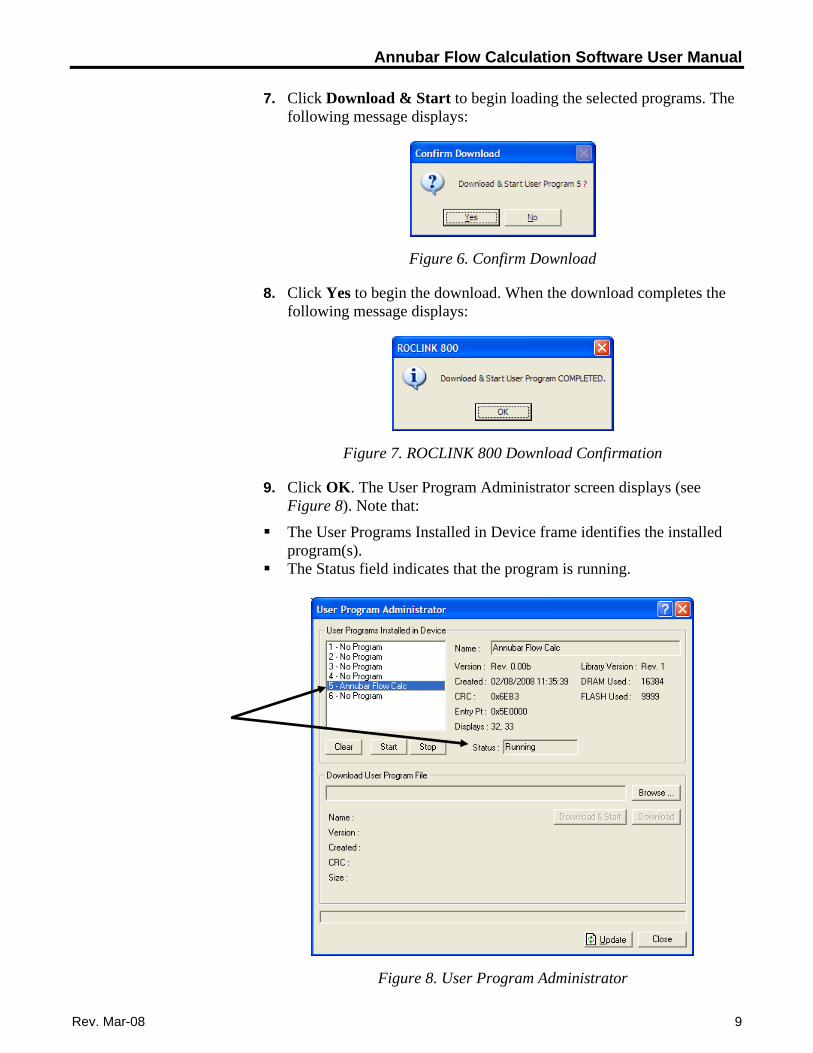
7. Click Download & Start to begin loading the selected programs. The following message displays:
Figure 6. Confirm Download
8. Click Yes to begin the download. When the download completes the following message displays:
Figure 7. ROCLINK 800 Download Confirmation
9. Click OK. The User Program Administrator screen displays (see Figure 8). Note that:
The User Programs Installed in Device frame identifies the installed program(s).
The Status field indicates that the program is running.
Figure 8. User Program Administrator
Rev. Mar-08 9

Annubar Flow Calculation Software User Manual
10 Rev. Mar-08
Note: If you install the program before you install the license key, the Status field reads “License Key Not Found.”
10. Click Close. The ROCLINK 800 screen displays and the download is complete.
Annubar Flow Calculation Software User Manual
Chapter 3 – Configuration
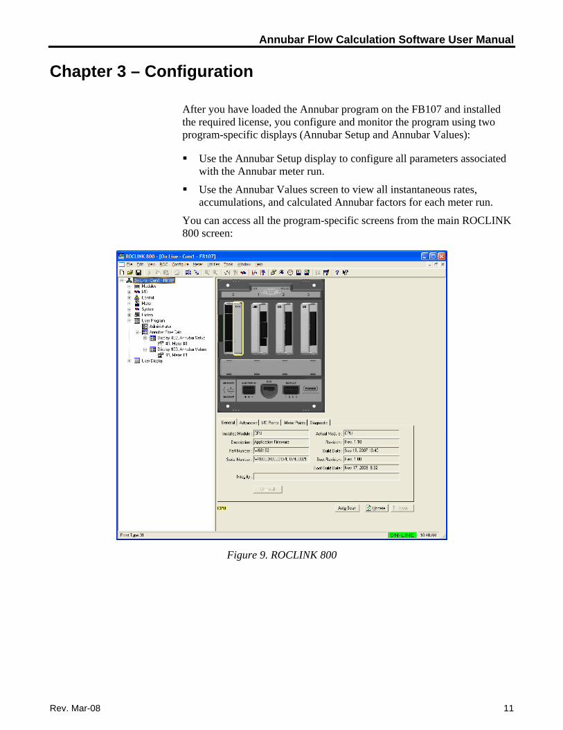
After you have loaded the Annubar program on the FB107 and installed the required license, you configure and monitor the program using two program-specific displays (Annubar Setup and Annubar Values):
Use the Annubar Setup display to configure all parameters associated with the Annubar meter run.
Use the Annubar Values screen to view all instantaneous rates, accumulations, and calculated Annubar factors for each meter run.
You can access all the program-specific screens from the main ROCLINK 800 screen:
Figure 9. ROCLINK 800
Rev. Mar-08 11
Annubar Flow Calculation Software User Manual
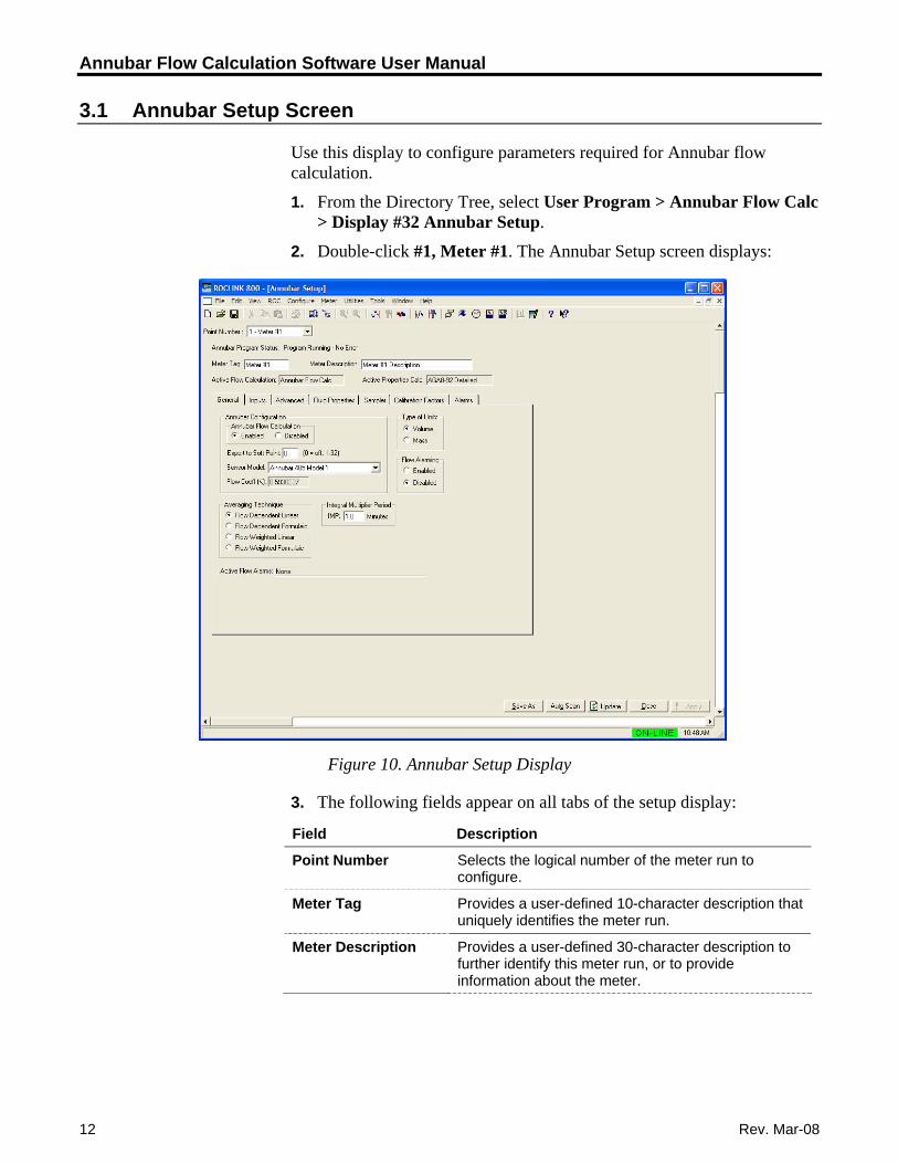
3.1 Annubar Setup Screen
Use this display to configure parameters required for Annubar flow calculation.
1. From the Directory Tree, select User Program > Annubar Flow Calc > Display #32 Annubar Setup.
2. Double-click #1, Meter #1. The Annubar Setup screen displays:
Figure 10. Annubar Setup Display
3. The following fields appear on all tabs of the setup display:
Field Description
Selects the logical number of the meter run to configure.
Point Number
Provides a user-defined 10-character description that uniquely identifies the meter run.
Meter Tag
Provides a user-defined 30-character description to further identify this meter run, or to provide information about the meter.
Meter Description
12 Rev. Mar-08
Annubar Flow Calculation Software User Manual
Rev. Mar-08 13
Field Description
Active Flow Calculation
This read-only field shows the calculation standard in use for calculating flow rate. For meter runs with the Annubar calculation enabled, this field always shows Annubar Flow Calc. When the Annubar calculation is not enabled and the FloBoss 107 internal flow calculations are active, this field shows either AGA3-92, AGA7-96, or ISO5167-2003.
Active Properties Calc
This read-only field shows the gas or fluid properties calculation the program uses to calculate and provide gas compressibility, density, and heating value.
Note: For gas volume calculations, this field may show AGA8 1992 Detailed if the FloBoss 107 internal AGA8 properties calculation is active. If a separate gas properties user program is active in the unit, the field displays the name of the standards calculation implemented in that program.
4. Click Apply to save any changes you have made to this screen.
5. Proceed to Section 3.1.1 to define the General tab.
Annubar Flow Calculation Software User Manual
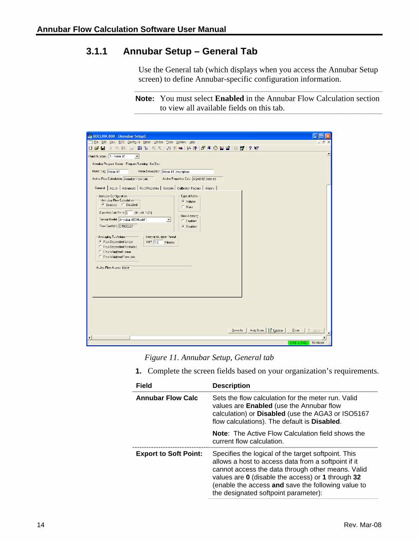
3.1.1 Annubar Setup – General Tab
Use the General tab (which displays when you access the Annubar Setup screen) to define Annubar-specific configuration information.
Note: You must select Enabled in the Annubar Flow Calculation section to view all available fields on this tab.
Figure 11. Annubar Setup, General tab
1. Complete the screen fields based on your organization’s requirements.
Field Description
Sets the flow calculation for the meter run. Valid values are Enabled (use the Annubar flow calculation) or Disabled (use the AGA3 or ISO5167 flow calculations). The default is Disabled.
Annubar Flow Calc
Note: The Active Flow Calculation field shows the current flow calculation.
Specifies the logical of the target softpoint. This allows a host to access data from a softpoint if it cannot access the data through other means. Valid values are 0 (disable the access) or 1 through 32 (enable the access and save the following value to the designated softpoint parameter):
Export to Soft Point:
14 Rev. Mar-08
Annubar Flow Calculation Software User Manual
Rev. Mar-08 15
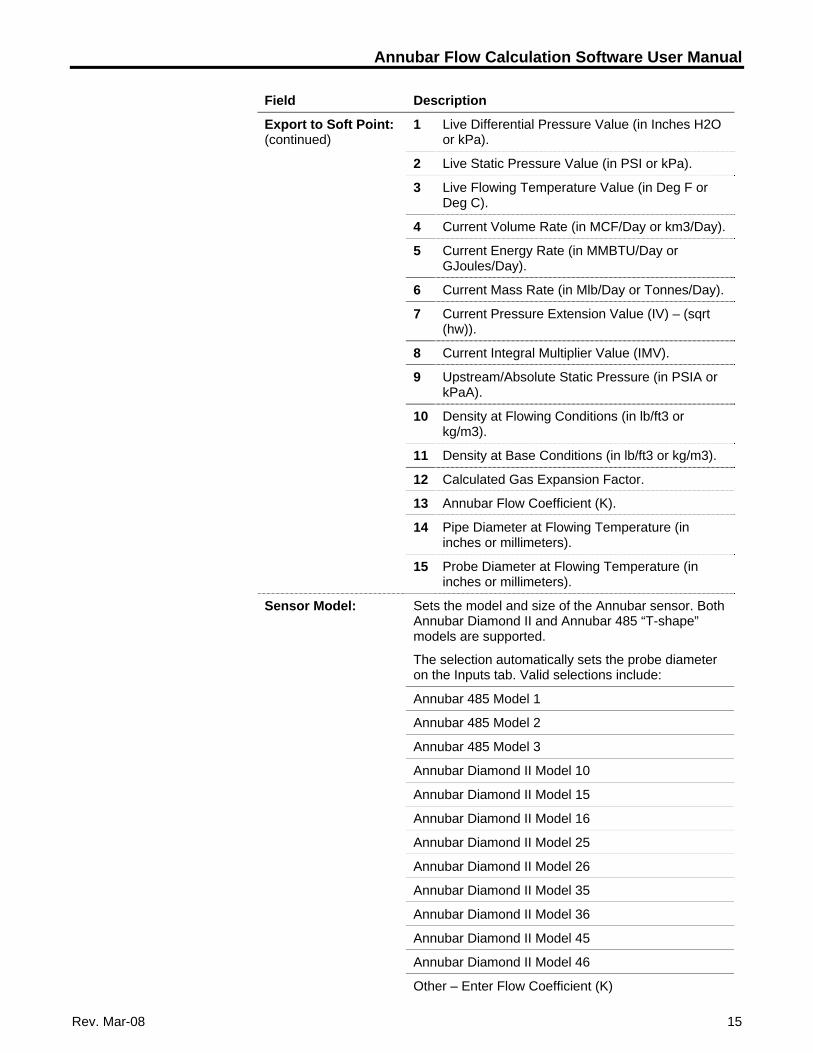
Field Description
Export to Soft Point: (continued)
1 Live Differential Pressure Value (in Inches H2O or kPa).
2 Live Static Pressure Value (in PSI or kPa).
3 Live Flowing Temperature Value (in Deg F or Deg C).
4 Current Volume Rate (in MCF/Day or km3/Day).
5 Current Energy Rate (in MMBTU/Day or GJoules/Day).
6 Current Mass Rate (in Mlb/Day or Tonnes/Day).
7 Current Pressure Extension Value (IV) – (sqrt (hw)).
8 Current Integral Multiplier Value (IMV).
9 Upstream/Absolute Static Pressure (in PSIA or kPaA).
10 Density at Flowing Conditions (in lb/ft3 or kg/m3).
11 Density at Base Conditions (in lb/ft3 or kg/m3).
12 Calculated Gas Expansion Factor.
13 Annubar Flow Coefficient (K).
14 Pipe Diameter at Flowing Temperature (in inches or millimeters).
15 Probe Diameter at Flowing Temperature (in inches or millimeters).
Sensor Model: Sets the model and size of the Annubar sensor. Both Annubar Diamond II and Annubar 485 “T-shape” models are supported.
The selection automatically sets the probe diameter on the Inputs tab. Valid selections include:
Annubar 485 Model 1
Annubar 485 Model 2
Annubar 485 Model 3
Annubar Diamond II Model 10
Annubar Diamond II Model 15
Annubar Diamond II Model 16
Annubar Diamond II Model 25
Annubar Diamond II Model 26
Annubar Diamond II Model 35
Annubar Diamond II Model 36
Annubar Diamond II Model 45
Annubar Diamond II Model 46
Other – Enter Flow Coefficient (K)
Annubar Flow Calculation Software User Manual
16 Rev. Mar-08
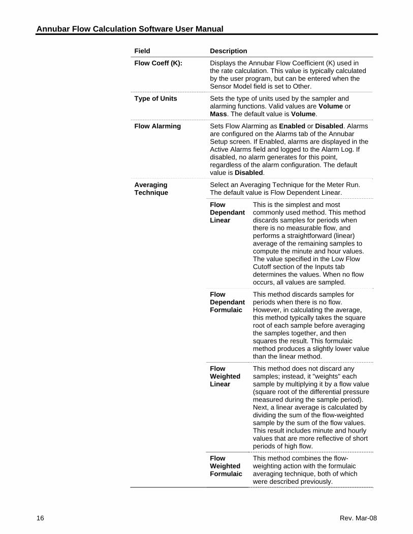
Field Description
Flow Coeff (K): Displays the Annubar Flow Coefficient (K) used in the rate calculation. This value is typically calculated by the user program, but can be entered when the Sensor Model field is set to Other.
Type of Units Sets the type of units used by the sampler and alarming functions. Valid values are Volume or Mass. The default value is Volume.
Flow Alarming Sets Flow Alarming as Enabled or Disabled. Alarms are configured on the Alarms tab of the Annubar Setup screen. If Enabled, alarms are displayed in the Active Alarms field and logged to the Alarm Log. If disabled, no alarm generates for this point, regardless of the alarm configuration. The default value is Disabled.
Averaging Technique
Select an Averaging Technique for the Meter Run. The default value is Flow Dependent Linear.
Flow Dependant Linear
This is the simplest and most commonly used method. This method discards samples for periods when there is no measurable flow, and performs a straightforward (linear) average of the remaining samples to compute the minute and hour values. The value specified in the Low Flow Cutoff section of the Inputs tab determines the values. When no flow occurs, all values are sampled.
Flow Dependant Formulaic
This method discards samples for periods when there is no flow. However, in calculating the average, this method typically takes the square root of each sample before averaging the samples together, and then squares the result. This formulaic method produces a slightly lower value than the linear method.
Flow Weighted Linear
This method does not discard any samples; instead, it "weights" each sample by multiplying it by a flow value (square root of the differential pressure measured during the sample period). Next, a linear average is calculated by dividing the sum of the flow-weighted sample by the sum of the flow values. This result includes minute and hourly values that are more reflective of short periods of high flow.
Flow Weighted Formulaic
This method combines the flow-weighting action with the formulaic averaging technique, both of which were described previously.
Annubar Flow Calculation Software User Manual
Rev. Mar-08 17
Field Description
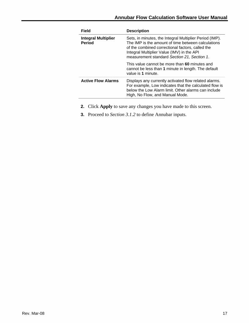
Integral Multiplier Period
Sets, in minutes, the Integral Multiplier Period (IMP). The IMP is the amount of time between calculations of the combined correctional factors, called the Integral Multiplier Value (IMV) in the API measurement standard Section 21, Section 1.
This value cannot be more than 60 minutes and cannot be less than 1 minute in length. The default value is 1 minute.
Active Flow Alarms Displays any currently activated flow related alarms. For example, Low indicates that the calculated flow is below the Low Alarm limit. Other alarms can include High, No Flow, and Manual Mode.
2. Click Apply to save any changes you have made to this screen.
3. Proceed to Section 3.1.2 to define Annubar inputs.
Annubar Flow Calculation Software User Manual
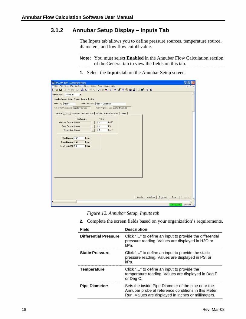
3.1.2 Annubar Setup Display – Inputs Tab
The Inputs tab allows you to define pressure sources, temperature source, diameters, and low flow cutoff value.
Note: You must select Enabled in the Annubar Flow Calculation section of the General tab to view the fields on this tab.
1. Select the Inputs tab on the Annubar Setup screen.
Figure 12. Annubar Setup, Inputs tab
2. Complete the screen fields based on your organization’s requirements.
Field Description Click “…” to define an input to provide the differential pressure reading. Values are displayed in H2O or kPa.
Differential Pressure
Click “…” to define an input to provide the static pressure reading. Values are displayed in PSI or kPa.
Static Pressure
Click “…” to define an input to provide the temperature reading. Values are displayed in Deg F or Deg C.
Temperature
Sets the inside Pipe Diameter of the pipe near the Annubar probe at reference conditions in this Meter Run. Values are displayed in inches or millimeters.
Pipe Diameter:
18 Rev. Mar-08
Annubar Flow Calculation Software User Manual
Rev. Mar-08 19
Field Description Probe Diameter: Sets the Annubar probe diameter at reference
conditions.
Note: This field is read-only and the value is set by the program unless you select Other – Enter Flow Coefficient (K) in the Sensor Model field on the General tab.
Low Flow CutOff: Enter a value for the Low Flow CutOff. When the differential pressure value of the metering device falls below this value, the calculated flow rate is set to zero and a No Flow alarm is recorded in the Alarm Log if Alarming is Enabled. For the Annubar calculation method, this value is in terms of inches of water column or kPa.
3. Click Apply to save any changes you have made to this screen.
4. Proceed to Section 3.1.3 to define Annubar advanced configuration.
Annubar Flow Calculation Software User Manual
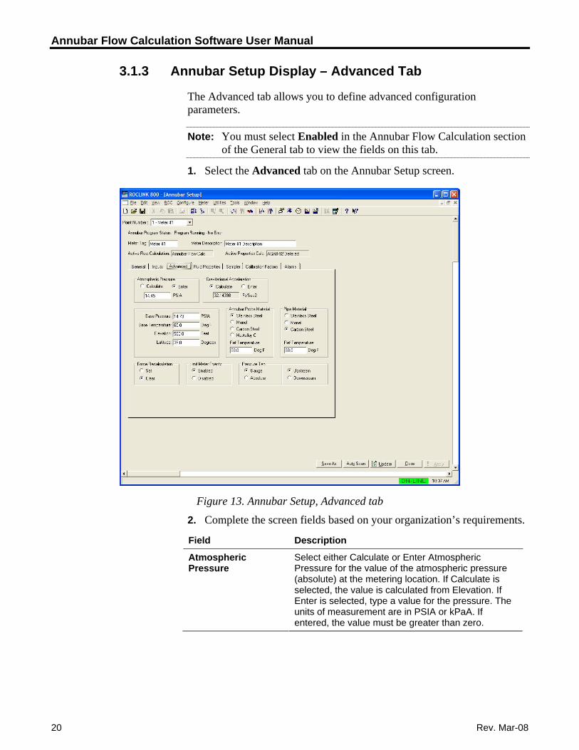
3.1.3 Annubar Setup Display – Advanced Tab
The Advanced tab allows you to define advanced configuration parameters.
Note: You must select Enabled in the Annubar Flow Calculation section of the General tab to view the fields on this tab.
1. Select the Advanced tab on the Annubar Setup screen.
Figure 13. Annubar Setup, Advanced tab
2. Complete the screen fields based on your organization’s requirements.
Field Description
Select either Calculate or Enter Atmospheric Pressure for the value of the atmospheric pressure (absolute) at the metering location. If Calculate is selected, the value is calculated from Elevation. If Enter is selected, type a value for the pressure. The units of measurement are in PSIA or kPaA. If entered, the value must be greater than zero.
Atmospheric Pressure
20 Rev. Mar-08
Annubar Flow Calculation Software User Manual
Rev. Mar-08 21
Acceleration d, the value is calculated from elevation and
Field Description
Gravitational Select Calculate or Enter Gravitational Acceleration for the value at the metering location. If Calculate is selectelatitude. If Enter is selected, type a value for the acceleration. The units of measurement are in ft/sec2or M/sec2. If entered, the value must be greater thanzero.
Base Pressure d r
Enter the flow measurement Base Pressure specifiein the gas contract. The pressure units are in PSIA okPaA.
Base Temperature units
Enter the flow measurement Base Temperature specified in the gas contract. The temperature are in degrees Fahrenheit or degrees Celsius.
Elevation r meters. Elevation is required for
Enter the elevation of the metering location. Theunits are in feet othe calculation of atmospheric pressure and gravitational acceleration.
Latitude atitude of the metering Enter the geographic Llocation. Latitude is required for calculation of gravitational acceleration. The units are in degrees and minutes, separated by a decimal point. For example: 46.15.
Annubar Probe Material
d
Select the material the Annubar probe is constructeof. Valid Values are Stainless Steel, Monel, CarbonSteel, or Hastelloy C.
Ref Temperature (Annubar Probe)
Sets the temperature at which the bore diameter of the probe was measured. Values are displayed in Deg F or Deg C.
Pipe Material Select the meter tube material (Pipe Material): Stainless Steel, Monel, or Carbon Steel. Nearly all natural gas applications use carbon steel meter tubes.
Ref Temperature (Pipe)
ter of Sets the temperature at which the inside diamethe pipe was measured. Values are displayed in Deg F or Deg C.
Force Recalculation e
Select Force Recalculation and click Apply to causa full recalculation of the flow without waiting for the next Normal recalculation. Normal recalculation periods are established in Annubar Setup screen using the Integral Multiplier Period. The Force Recalculation parameter is automatically set to Clearafter the recalculation completes.
Limit Meter Events
calculation is outside the specified limits or the calculation fails. Disable this parameter if the FloBoss should ignore AGA calculation related events. Disabling this parameter prevents the Event Log from filling with AGA limit type events.
Enable Limit Meter Events if the FloBoss is to log AGA events. An AGA limit event is logged when aninput to the AGA
Annubar Flow Calculation Software User Manual
22 Rev. Mar-08
ress
Field Description
Select the Pthis Meter Run.
ure Tap type and location used in
Gauge or Absolute
e
nsmitter can be bsolute or
Select either Gauge or Absolute asthe pressure tap type. This choice must match the static pressure typactually measured by the sensor. The MVS sensor, DVS sensor, or other pressure traordered to provide either agauge measurements. The default value is Gauge.
Pressure Tap
Upstream or Downstream n
pressure tap in relation ar element during
Select either Upstream or Downstream to indicate the locatioof the static to the Annubnormal flow. The default value is Upstream.
3. Click Apply to save any changes you have made to this screen.
4. Proceed to Section 3.1.4 to define fluid properties.
Annubar Flow Calculation Software User Manual
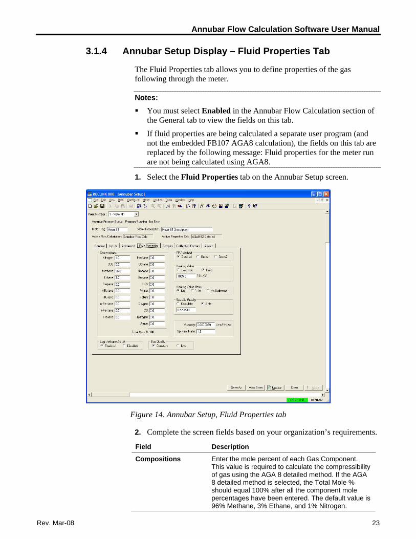
3.1.4 Annubar Setup Display – Fluid Properties Tab
The Fluid Properties tab allows you to define properties of the gas following through the meter.
Notes: You must select Enabled in the Annubar Flow Calculation section of
the General tab to view the fields on this tab.
If fluid properties are being calculated a separate user program (and not the embedded FB107 AGA8 calculation), the fields on this tab are replaced by the following message: Fluid properties for the meter run are not being calculated using AGA8.
1. Select the Fluid Properties tab on the Annubar Setup screen.
Figure 14. Annubar Setup, Fluid Properties tab
2. Complete the screen fields based on your organization’s requirements.
Field Description
Enter the mole percent of each Gas Component. This value is required to calculate the compressibility of gas using the AGA 8 detailed method. If the AGA 8 detailed method is selected, the Total Mole % should equal 100% after all the component mole percentages have been entered. The default value is 96% Methane, 3% Ethane, and 1% Nitrogen.
Compositions
Rev. Mar-08 23
Annubar Flow Calculation Software User Manual
24 Rev. Mar-08
Field Description
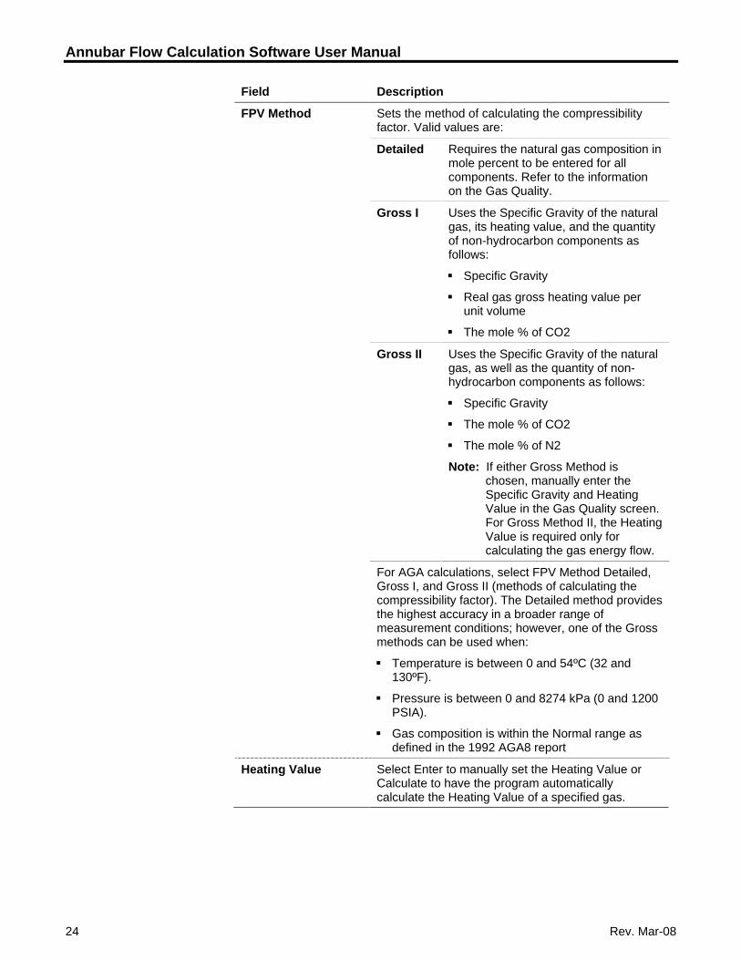
FPV Method Sets the method of calculating the compressibility factor. Valid values are:
Detailed Requires the natural gas composition in mole percent to be entered for all components. Refer to the information on the Gas Quality.
Gross I Uses the Specific Gravity of the natural gas, its heating value, and the quantity of non-hydrocarbon components as follows:
Specific Gravity
Real gas gross heating value per unit volume
The mole % of CO2
Gross II Uses the Specific Gravity of the natural gas, as well as the quantity of non-hydrocarbon components as follows:
Specific Gravity
The mole % of CO2
The mole % of N2
Note: If either Gross Method is chosen, manually enter the Specific Gravity and Heating Value in the Gas Quality screen. For Gross Method II, the Heating Value is required only for calculating the gas energy flow.
For AGA calculations, select FPV Method Detailed, Gross I, and Gross II (methods of calculating the compressibility factor). The Detailed method provides the highest accuracy in a broader range of measurement conditions; however, one of the Gross methods can be used when:
Temperature is between 0 and 54ºC (32 and 130ºF).
Pressure is between 0 and 8274 kPa (0 and 1200 PSIA).
Gas composition is within the Normal range as defined in the 1992 AGA8 report
Heating Value Select Enter to manually set the Heating Value or Calculate to have the program automatically calculate the Heating Value of a specified gas.
Annubar Flow Calculation Software User Manual
Rev. Mar-08 25
Field Description
Heating Value Basis Select between Dry (no water vapor present in the gas), Wet (saturated water vapor present in the gas), or As Delivered (may contain some water vapor) for the Heating Value Basis. This selection indicates on what basis the entered Heating Value was determined and affects the flow or energy calculations.
If Wet Gas selected, the FB107 calculates the mole percentage of water based on the algorithm from IAPWS – IF97 standards and adjusts the other mole percentages accordingly.
Specific Gravity Select either Calculate or Enter for the Spec Gravity ratio of the molar mass of the gas to the molar mass of air. The value entered for standard conditions is used in the flow calculation. The Specific Gravity value cannot be less than 0.07.
If Calculate, the FloBoss calculates the Specific Gravity value to be used in the flow calculations.
If Enter, the value entered is used in the flow calculation. The Specific Gravity should be entered for the gas at standard conditions and cannot be less than 0.07.
Viscosity: Enter the dynamic Viscosity of the flowing gas. The units of measure will be either Lbm/Ft-Sec for US Units or cP for Metric Units.
Sp Heat Ratio: Enter the Specific Heat Ratio (Sp Heat Ratio) of the gas (defined as the specific heat of the gas at constant pressure divided by the specific heat of the gas at constant volume). Accepted practice for natural gas applications is to use a value of 1.3, which was used to develop the expansion factor tables in the AGA 3 Report – Part 3. If entered, the value must be greater than zero.
Log Methane Adjust If the percentages are automatically adjusted to total 100 and you would like to log this adjustment, select Enabled in the Log Methane Adjust field. If you select Disable, this does not prevent the FloBoss from automatically adjusting the Methane, but does prevent an Event Log entry.
Gas Quality The Gas Quality field determines where to get Gas Quality readings. Live indicates readings come from a gas chromatograph or periodically downloaded from a host and changes are not entered in the Event Log. Constant indicates that the changes are entered in the Event Log.
3. Click Apply to save any changes you have made to this screen.
4. Proceed to Section 3.1.5 to define sampler setup.
Annubar Flow Calculation Software User Manual
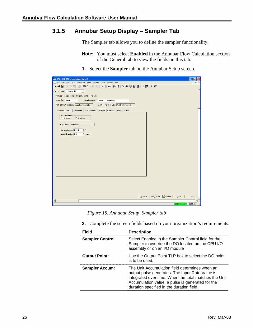
3.1.5 Annubar Setup Display – Sampler Tab
The Sampler tab allows you to define the sampler functionality.
Note: You must select Enabled in the Annubar Flow Calculation section of the General tab to view the fields on this tab.
1. Select the Sampler tab on the Annubar Setup screen.
Figure 15. Annubar Setup, Sampler tab
2. Complete the screen fields based on your organization’s requirements.
Field Description Select Enabled in the Sampler Control field for the Sampler to override the DO located on the CPU I/O assembly or on an I/O module
Sampler Control
Use the Output Point TLP box to select the DO point is to be used.
Output Point:
The Unit Accumulation field determines when an output pulse generates. The Input Rate Value is integrated over time. When the total matches the Unit Accumulation value, a pulse is generated for the duration specified in the duration field.
Sampler Accum:
26 Rev. Mar-08
Annubar Flow Calculation Software User Manual
Rev. Mar-08 27
Field Description Sampler Duration: The Duration is how long (in seconds) the output
pulse will be on. This is how long the DO stays ON. The DO is turned on for the amount of time set in the Duration field every time the Unit Accumulation value is exceeded.
3. Click Apply to save any changes you have made to this screen.
4. Proceed to Section 3.1.6 to define calibration factors.
Annubar Flow Calculation Software User Manual
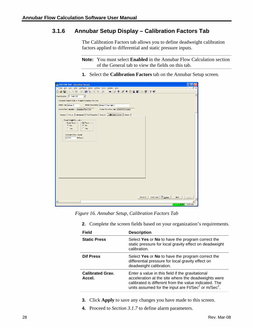
3.1.6 Annubar Setup Display – Calibration Factors Tab
The Calibration Factors tab allows you to define deadweight calibration factors applied to differential and static pressure inputs.
Note: You must select Enabled in the Annubar Flow Calculation section of the General tab to view the fields on this tab.
1. Select the Calibration Factors tab on the Annubar Setup screen.
Figure 16. Annubar Setup, Calibration Factors Tab
2. Complete the screen fields based on your organization’s requirements.
Field Description Select Yes or No to have the program correct the static pressure for local gravity effect on deadweight calibration.
Static Press
Select Yes or No to have the program correct the differential pressure for local gravity effect on deadweight calibration.
Dif Press
Enter a value in this field if the gravitational acceleration at the site where the deadweights were calibrated is different from the value indicated. The units assumed for the input are Ft/Sec2 or m/Sec2.
Calibrated Grav. Accel.
3. Click Apply to save any changes you have made to this screen.
28 Rev. Mar-08
4. Proceed to Section 3.1.7 to define alarm parameters.
Annubar Flow Calculation Software User Manual
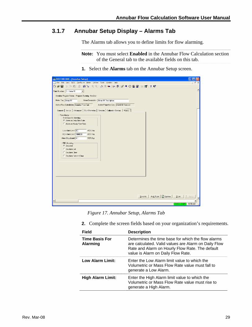
3.1.7 Annubar Setup Display – Alarms Tab
The Alarms tab allows you to define limits for flow alarming.
Note: You must select Enabled in the Annubar Flow Calculation section of the General tab to the available fields on this tab.
1. Select the Alarms tab on the Annubar Setup screen.
Figure 17. Annubar Setup, Alarms Tab
2. Complete the screen fields based on your organization’s requirements.
Field Description Determines the time base for which the flow alarms are calculated. Valid values are Alarm on Daily Flow Rate and Alarm on Hourly Flow Rate. The default value is Alarm on Daily Flow Rate.
Time Basis For Alarming
Enter the Low Alarm limit value to which the Volumetric or Mass Flow Rate value must fall to generate a Low Alarm.
Low Alarm Limit:
Enter the High Alarm limit value to which the Volumetric or Mass Flow Rate value must rise to generate a High Alarm.
High Alarm Limit:
Rev. Mar-08 29
Annubar Flow Calculation Software User Manual
30 Rev. Mar-08
Field Description Alarm Deadband: Enter the amount of time, in seconds, that is an
inactive zone before and after the flow alarm is triggered. The purpose of the Alarm Deadband Time is to prevent the alarm from being set and cleared continuously when the input value is oscillating around the alarm limit.
RBX Alarming Select the RBX Alarming option to configure Spontaneous-Report-by-Exception (SRBX or RBX) alarming for this point.
Disabled – The RBX Alarming is turned off.
On Alarm Set – When the point enters an alarm condition, the FloBoss generates a Spontaneous-Report-by-Exception message to the host.
On Alarm Clear – When the point leaves an alarm condition, the FloBoss generates a Spontaneous-Report-by-Exception message to the host.
On Alarm Set and Clear – In either condition, an RBX message generates to the host.
Note: RBX Alarming requires the communications port to be properly configured for RBX Alarming.
3. Click Apply to save any changes you have made to this screen.
4. Proceed to Section 3.2 to view flow rates, accumulations and calculated factors associated with the Annubar flow calculation.
Annubar Flow Calculation Software User Manual
3.2 Annubar Values Screen
Use this display to view flow rates, accumulations and calculated factors associated with the Annubar flow calculation.
1. From the Directory Tree, select User Program > Annubar Flow Calc > Display #33 Annubar Values.
2. Double-click #1, Meter Tag. The Annubar Values screen displays:
Figure 18. Annubar Values Screen
3. The following fields appear on all tabs of the setup display:
Field Description Selects the logical number of the meter run to view. Point Number
This read-only field shows a 10-character description that uniquely identifies the meter run.
Meter Tag
This read-only field shows a 30-character description to further identify this meter run, or to provide information about the meter.
Meter Description
Rev. Mar-08 31
Annubar Flow Calculation Software User Manual
32 Rev. Mar-08
Field Description Active Flow Calculation
This read-only field shows the calculation standard in use for calculating flow rate. For meter runs with the Annubar calculation enabled, this field always shows Annubar Flow Calc. When the Annubar calculation is not enabled and the FloBoss 107 internal flow calculations are active, this field shows either AGA3-92, AGA7-96, or ISO5167-2003.
Active Properties Calc
This read-only field shows the gas or fluid properties calculation the program uses to calculate and provide gas compressibility, density, and heating value.
Note: For gas volume calculations, this field may show AGA8 1992 Detailed if the FloBoss 107 internal AGA8 properties calculation is active. If a separate gas properties user program is active in the unit, the field displays the name of the standards calculation implemented in that program.
4. Proceed to Section 3.2.1 to view totals on the Current Values tab.
Annubar Flow Calculation Software User Manual
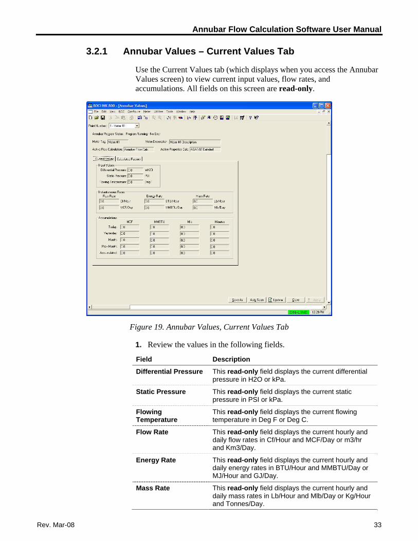
3.2.1 Annubar Values – Current Values Tab
Use the Current Values tab (which displays when you access the Annubar Values screen) to view current input values, flow rates, and accumulations. All fields on this screen are read-only.
Figure 19. Annubar Values, Current Values Tab
1. Review the values in the following fields.
Field Description
This read-only field displays the current differential pressure in H2O or kPa.
Differential Pressure
This read-only field displays the current static pressure in PSI or kPa.
Static Pressure
This read-only field displays the current flowing temperature in Deg F or Deg C.
Flowing Temperature
This read-only field displays the current hourly and daily flow rates in Cf/Hour and MCF/Day or m3/hr and Km3/Day.
Flow Rate
This read-only field displays the current hourly and daily energy rates in BTU/Hour and MMBTU/Day or MJ/Hour and GJ/Day.
Energy Rate
This read-only field displays the current hourly and daily mass rates in Lb/Hour and Mlb/Day or Kg/Hour and Tonnes/Day.
Mass Rate
Rev. Mar-08 33
Annubar Flow Calculation Software User Manual
34 Rev. Mar-08
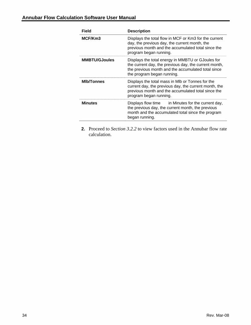
Field Description
MCF/Km3 Displays the total flow in MCF or Km3 for the current day, the previous day, the current month, the previous month and the accumulated total since the program began running.
MMBTU/GJoules Displays the total energy in MMBTU or GJoules for the current day, the previous day, the current month, the previous month and the accumulated total since the program began running.
Mlb/Tonnes Displays the total mass in Mlb or Tonnes for the current day, the previous day, the current month, the previous month and the accumulated total since the program began running.
Minutes Displays flow time in Minutes for the current day, the previous day, the current month, the previous month and the accumulated total since the program began running.
2. Proceed to Section 3.2.2 to view factors used in the Annubar flow rate calculation.
Annubar Flow Calculation Software User Manual
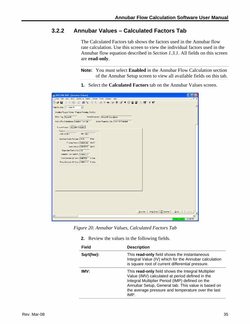
3.2.2 Annubar Values – Calculated Factors Tab
The Calculated Factors tab shows the factors used in the Annubar flow rate calculation. Use this screen to view the individual factors used in the Annubar flow equation described in Section 1.3.1. All fields on this screen are read-only.
Note: You must select Enabled in the Annubar Flow Calculation section of the Annubar Setup screen to view all available fields on this tab.
1. Select the Calculated Factors tab on the Annubar Values screen.
Figure 20. Annubar Values, Calculated Factors Tab
2. Review the values in the following fields.
Field Description
This read-only field shows the instantaneous Integral Value (IV) which for the Annubar calculation is square root of current differential pressure.
Sqrt(hw):
This read-only field shows the Integral Multiplier Value (IMV) calculated at period defined in the Integral Multiplier Period (IMP) defined on the Annubar Setup, General tab. This value is based on the average pressure and temperature over the last IMP.
IMV:
Rev. Mar-08 35
Annubar Flow Calculation Software User Manual
36 Rev. Mar-08
Field Description
Upstream Static Pressure:
This read-only field shows the static pressure corrected to absolute upstream conditions in psia or KpaA.
Flowing Density: This read-only field shows the calculated density at flowing conditions in lb/cf or Kg/m3.
Base Density: This read-only field shows the calculated density at base conditions in lb/cf or Kg/m3.
Expansion Factor (Ya):
This read-only field shows the gas expansion factor used in the flow rate calculation. The expansion factor adjusts for density and internal energy effects of a gas as it flows around the Annubar primary element. The expansion factor is set to 1.0 for liquid applications.
Annubar Flow Coeff (K):
This read-only field shows the Annubar Flow Coefficient (K) used in the flow calculation. This value may be calculated by the user program or manually entered.
Pipe Diameter @ Temp:
This read-only field shows the adjusted pipe diameter at flowing temperature in inches or millimeters.
Probe Diameter @ Temp:
This read-only field shows the adjusted probe diameter at flowing temperature in inches or millimeters.
3. Proceed to Section 3.3 to save the configuration to non-volatile memory and/or to file.
Annubar Flow Calculation Software User Manual
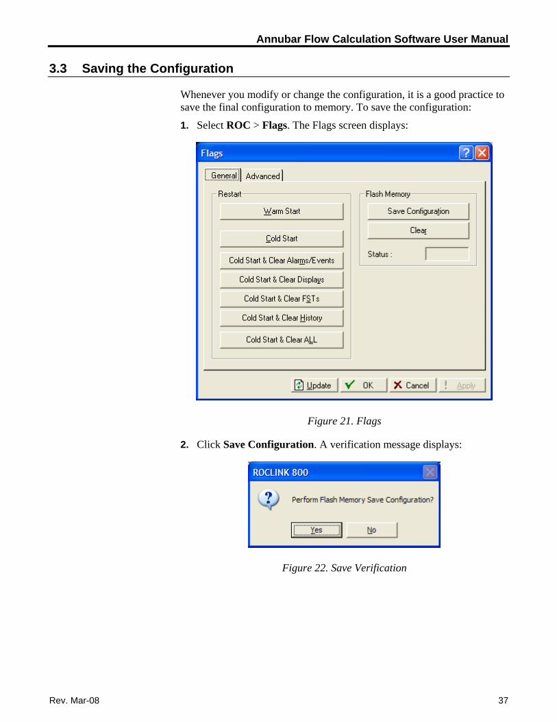
3.3 Saving the Configuration
Whenever you modify or change the configuration, it is a good practice to save the final configuration to memory. To save the configuration:
1. Select ROC > Flags. The Flags screen displays:
Figure 21. Flags
2. Click Save Configuration. A verification message displays:
Figure 22. Save Verification
Rev. Mar-08 37
Annubar Flow Calculation Software User Manual
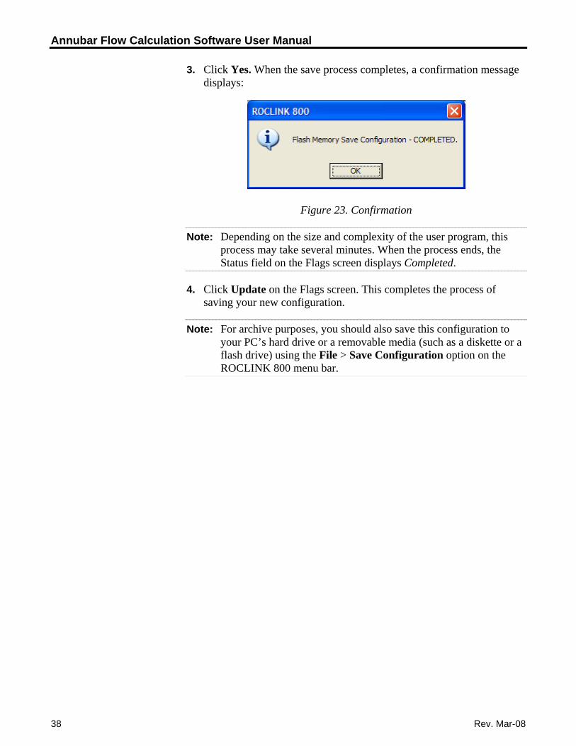
3. Click Yes. When the save process completes, a confirmation message displays:
Figure 23. Confirmation
Note: Depending on the size and complexity of the user program, this process may take several minutes. When the process ends, the Status field on the Flags screen displays Completed.
4. Click Update on the Flags screen. This completes the process of saving your new configuration.
Note: For archive purposes, you should also save this configuration to your PC’s hard drive or a removable media (such as a diskette or a flash drive) using the File > Save Configuration option on the ROCLINK 800 menu bar.
38 Rev. Mar-08

Annubar Flow Calculation Software User Manual
Rev. Mar-08 39
Chapter 4 – Reference Materials
This section provides tables of information on the user-defined point types used by the Annubar Flow Calculation program.
Point Type 31: Annubar Configuration
Point Type 32: Annubar Flow Calculation Values
Annubar Flow Calculation Software User Manual
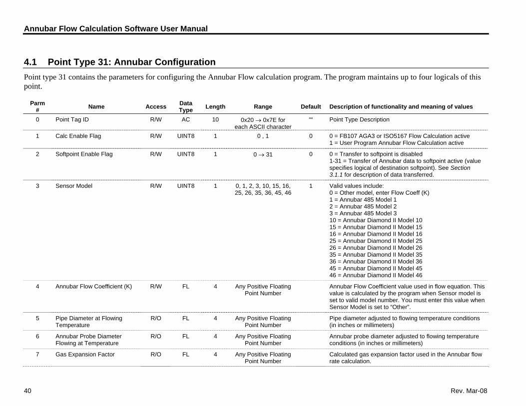
4.1 Point Type 31: Annubar Configuration Point type 31 contains the parameters for configuring the Annubar Flow calculation program. The program maintains up to four logicals of this point.
Parm # Name Access Data
Type Length Range Default Description of functionality and meaning of values
0 Point Tag ID R/W AC 10 ““ Point Type Description 0x20 → 0x7E for each ASCII character
1 Calc Enable Flag R/W UINT8 1 0 , 1 0 0 = FB107 AGA3 or ISO5167 Flow Calculation active 1 = User Program Annubar Flow Calculation active
2 Softpoint Enable Flag R/W UINT8 1 0 0 = Transfer to softpoint is disabled 0 → 31 1-31 = Transfer of Annubar data to softpoint active (value specifies logical of destination softpoint). See Section 3.1.1 for description of data transferred.
3 Sensor Model R/W UINT8 1 0, 1, 2, 3, 10, 15, 16, 25, 26, 35, 36, 45, 46
1 Valid values include: 0 = Other model, enter Flow Coeff (K) 1 = Annubar 485 Model 1 2 = Annubar 485 Model 2 3 = Annubar 485 Model 3 10 = Annubar Diamond II Model 10 15 = Annubar Diamond II Model 15 16 = Annubar Diamond II Model 16 25 = Annubar Diamond II Model 25 26 = Annubar Diamond II Model 26 35 = Annubar Diamond II Model 35 36 = Annubar Diamond II Model 36 45 = Annubar Diamond II Model 45 46 = Annubar Diamond II Model 46
4 Annubar Flow Coefficient (K) R/W FL 4 Any Positive Floating Point Number
Annubar Flow Coefficient value used in flow equation. This value is calculated by the program when Sensor model is set to valid model number. You must enter this value when Sensor Model is set to “Other”.
5 Pipe Diameter at Flowing Temperature
R/O FL 4 Any Positive Floating Point Number
Pipe diameter adjusted to flowing temperature conditions (in inches or millimeters)
6 Annubar Probe Diameter Flowing at Temperature
R/O FL 4 Any Positive Floating Point Number
Annubar probe diameter adjusted to flowing temperature conditions (in inches or millimeters)
7 Gas Expansion Factor R/O FL 4 Any Positive Floating Point Number
Calculated gas expansion factor used in the Annubar flow rate calculation.
40 Rev. Mar-08
Annubar Flow Calculation Software User Manual
Revised Mar-08 41
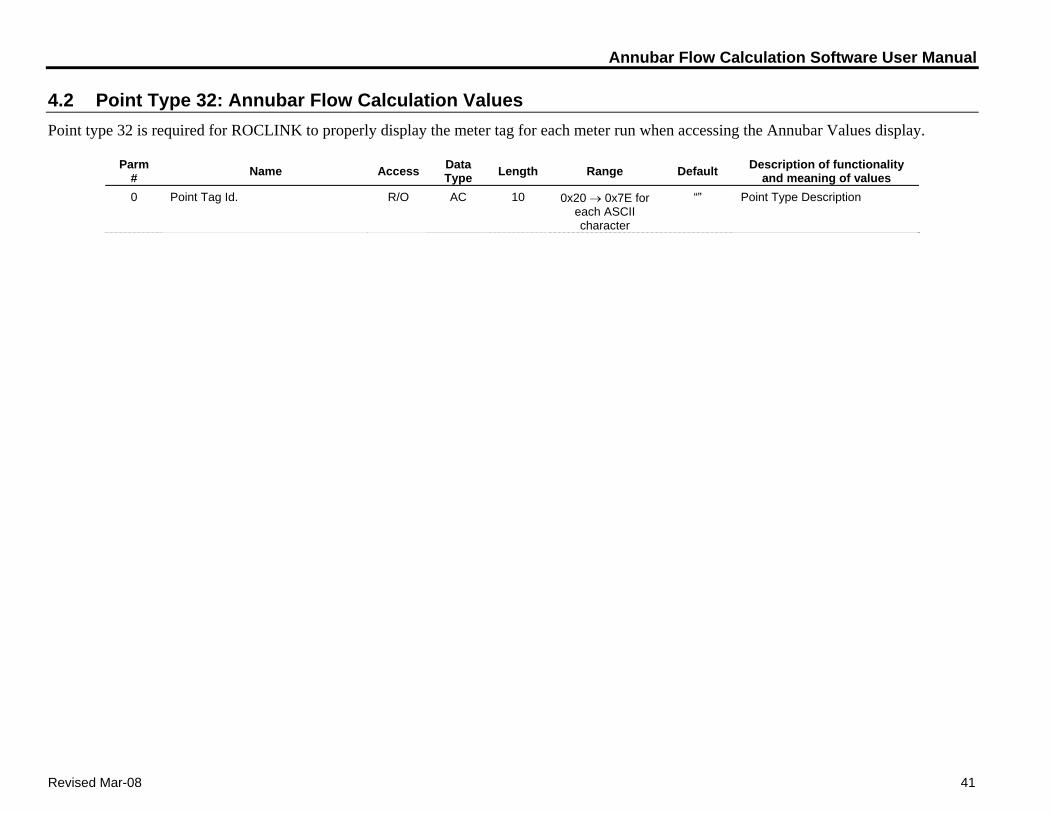
4.2 Point Type 32: Annubar Flow Calculation Values Point type 32 is required for ROCLINK to properly display the meter tag for each meter run when accessing the Annubar Values display.
Parm # Name Access Data
Type Length Range Default Description of functionality and meaning of values
0 Point Tag Id. R/O AC 10 0x20 → 0x7E for each ASCII character
“” Point Type Description

Annubar Flow Calculation Software User Manual
If you have comments or questions regarding this manual, please direct them to your local sales representative or contact: Emerson Process Management Remote Automation Solutions Marshalltown, Iowa 50158 USA Houston, TX 77065 USA Pickering, North Yorkshire UK Y018 7JA Website: www.EmersonProcess.com/Remote