Embed Size (px)
Citation preview
MPEG4 Video Verification Model VM 8.0
INTERNATIONAL ORGANISATION FOR STANDARDISATIONORGANISATION INTERNATIONALE DE NORMALISATION
ISO/IEC JTC1/SC29/WG11CODING OF MOVING PICTURES AND ASSOCIATED AUDIO
INFORMATION
ISO/IEC JTC1/SC29/WG11
MPEG97/N1796Stockholm, July1997
Source: Video Group
Status: Draft in Progress
Title: MPEG-4 Video Verification Model Version 8.0
Editor: Touradj Ebrahimi
1

MPEG4 Video Verification Model VM 8.0
Please address all comments or suggestions to the ad hoc group on MPEG-4 video VM editing mail reflector ‘[email protected]’.
2
MPEG4 Video Verification Model VM 8.0
Table of Contents
1 Introduction.................................................................................................................................................... 9
2 Video Object Plane (VOP).......................................................................................................................... 11
2.1 VOP Definition...................................................................................................................................... 11
2.2 VOP format........................................................................................................................................... 12
2.2.1 Test sequences library.................................................................................................................... 12
2.2.2 Filtering process............................................................................................................................. 14
2.2.3 VOP file format............................................................................................................................. 17
2.2.4 Coding of test sequences whose width and height are not integral multiples of 16..........................17
3 Encoder Definition...................................................................................................................................... 18
3.1 Overview............................................................................................................................................... 18
3.1.1 VOP formation............................................................................................................................... 19
3.2 Shape Coding........................................................................................................................................ 20
3.2.1 Overview....................................................................................................................................... 20
3.2.2 Abbreviations................................................................................................................................. 20
3.2.3 Mode Decision............................................................................................................................... 21
3.2.4 Motion estimation and compensation.............................................................................................23
3.2.5 Size conversion (Rate control)........................................................................................................ 25
3.2.6 Binary Alpha Block Coding...........................................................................................................30
3.2.7 Grey Scale Shape Coding...............................................................................................................34
3.3 Motion Estimation and Compensation...................................................................................................39
3.3.1 Padding Process............................................................................................................................. 39
3.3.2 Basic Motion Techniques............................................................................................................... 43
3.3.3 Unrestricted Motion Estimation/Compensation..............................................................................47
3.3.4 Advanced prediction mode.............................................................................................................48
3.3.5 Interlaced Motion Compensation....................................................................................................51
3.4 Texture Coding...................................................................................................................................... 52
3.4.1 Low Pass Extrapolation (LPE) Padding Technique.........................................................................52
3.4.2 Adaptive Frame/Field DCT............................................................................................................ 53
3.4.3 DCT............................................................................................................................................... 53
3.4.4 SA-DCT......................................................................................................................................... 55
3.4.5 H263 Quantization Method............................................................................................................ 58
3.4.6 MPEG Quantization Method.......................................................................................................... 59
3.4.7 Intra DC and AC Prediction for I-VOP and P-VOP........................................................................64
3.4.8 VLC encoding of quantized transform coefficients.........................................................................67
3.5 Prediction and Coding of B-VOPs.........................................................................................................69
3
MPEG4 Video Verification Model VM 8.0
3.5.1 Direct Coding................................................................................................................................. 69
3.5.2 Forward Coding............................................................................................................................. 72
3.5.3 Backward Coding........................................................................................................................... 72
3.5.4 Bidirectional Coding...................................................................................................................... 72
3.5.5 Mode Decisions............................................................................................................................. 73
3.5.6 Motion Vector Coding................................................................................................................... 73
3.6 Error Resilience..................................................................................................................................... 74
3.6.1 Introduction................................................................................................................................... 74
3.6.2 Recommended Modes of Operation................................................................................................77
3.7 Rate Control.......................................................................................................................................... 80
3.8 Generalized Scalable Encoding.............................................................................................................. 84
3.8.1 Spatial Scalability Encoding...........................................................................................................86
3.8.2 Temporal Scalability Encoding......................................................................................................88
3.9 Sprite Coding and Global Motion Compensation...................................................................................91
3.9.1 Introduction................................................................................................................................... 91
3.9.2 Location of Reference Points.........................................................................................................93
3.9.3 Definition of Transform Functions.................................................................................................95
3.9.4 Sprite Generation........................................................................................................................... 97
3.9.5 Encoding...................................................................................................................................... 101
3.10 Texture Coding Mode.......................................................................................................................... 106
3.10.1 Basic Principle of the Encoder.....................................................................................................109
3.10.2 Discrete Wavelet Transform......................................................................................................... 110
3.10.3 Coding of the lowest subband.......................................................................................................111
3.10.4 ZeroTree Coding of the Higher Bands..........................................................................................112
3.10.5 Quantization................................................................................................................................. 113
3.10.6 Zero Tree Scanning...................................................................................................................... 114
3.10.7 Entropy coding............................................................................................................................. 115
4 Bitstream Syntax....................................................................................................................................... 116
4.1 Definitions........................................................................................................................................... 116
4.2 General Structure................................................................................................................................. 117
4.3 Video Session Class............................................................................................................................. 118
4.3.1 Video Session Class..................................................................................................................... 118
4.4 Video Object Class.............................................................................................................................. 119
4.4.1 Video Object................................................................................................................................ 119
4.5 Video Object Layer Class.................................................................................................................... 120
4.5.1 Video Object Layer...................................................................................................................... 120
4.6 Group Of VOPs class........................................................................................................................... 131
4
MPEG4 Video Verification Model VM 8.0
4.6.1 Syntax of Group of VideoObjectPlane..........................................................................................131
4.7 VideoObjectPlane Class....................................................................................................................... 133
4.7.1 VideoObjectPlane........................................................................................................................ 133
4.8 Shape coding....................................................................................................................................... 154
4.9 Motion Shape Texture......................................................................................................................... 156
4.9.1 Combined Motion Shape Texture.................................................................................................156
4.9.2 Separate Motion Shape Texture Syntax for I-, P-, and B-VOPs.....................................................156
4.10 Texture Object Layer Class.................................................................................................................. 166
4.10.1 Texture Object Layer................................................................................................................... 166
5 Decoder Definition..................................................................................................................................... 171
5.1 Overview............................................................................................................................................. 171
5.2 Shape decoding.................................................................................................................................... 171
5.3 Decoding of Escape Code.................................................................................................................... 171
5.4 Temporal Prediction Structure.............................................................................................................172
5.5 Generalized Scalable Decoding............................................................................................................ 173
5.5.1 Spatial Scalability Decoding........................................................................................................174
5.5.2 Temporal Scalability Decoding....................................................................................................174
5.6 Compositer Definition......................................................................................................................... 176
5.7 Flex_0 Composition Layer Syntax.......................................................................................................176
5.7.1 Bitstream Syntax.......................................................................................................................... 176
5.7.2 Parameter Semantics.................................................................................................................... 177
6 Appendix A: Combined Motion Shape Texture Coding...........................................................................179
6.1 Macroblock Layer................................................................................................................................ 179
6.1.1 Coded macroblock indication (COD) (1 bit).................................................................................180
6.1.2 Macroblock type & Coded block pattern for chrominance (MCBPC) (Variable length)................180
6.1.3 MC reference indication (MCSEL) (1bit).....................................................................................183
6.1.4 Intra Prediction Acpred_flag (1bit)...............................................................................................183
6.1.5 Coded block pattern for luminance (CBPY) (Variable length)......................................................184
6.1.6 Quantizer Information (DQUANT) (1 or 2 bits)............................................................................184
6.1.7 Interlaced video coding information (Interlaced_information)......................................................186
6.1.8 Motion Vector Coding.................................................................................................................. 187
6.1.9 Motion vector data (MVD) (Variable length)................................................................................188
6.1.10 Motion vector data (MVD2-4) (Variable length).............................................................................190
6.1.11 Macroblock mode for B-blocks (MODB) (Variable length)..........................................................190
6.1.12 Macroblock Type (MBTYPE) for Coded B-VOPs (Variable length).............................................190
6.1.13 Coded block pattern for B-blocks (CBPB) (3-6 bits)....................................................................191
5
MPEG4 Video Verification Model VM 8.0
6.1.14 Quantizer Information for B-Macroblocks (DQUANT) (2 bits)....................................................191
6.1.15 Motion vector data for Forward Prediction (MVDf) (Variable length)...........................................192
6.1.16 Motion vector data for Backward Prediction (MVDb) (Variable length)........................................192
6.1.17 Motion vector data for Direct Prediction (MVDB) (Variable length)............................................192
6.2 Block Layer......................................................................................................................................... 192
6.2.1 DC Coefficient for INTRA blocks (INTRADC) (Variable length)................................................192
6.2.2 Transform coefficient (TCOEF) (Variable length)........................................................................195
6.2.3 Encoding of escape code.............................................................................................................. 195
6.3 Remultiplexing of Combined Motion Texture Coding Mode for Error Resilience................................201
7 Appendix B: Transform coefficient (TCOFF) (Variable length).............................................................203
8 Appendix C: Definition of Post- filter.......................................................................................................209
8.1 Deblocking filter.................................................................................................................................. 209
8.2 Deringing filter.................................................................................................................................... 210
8.2.1 Threshold determination............................................................................................................... 211
8.2.2 Index acquisition.......................................................................................................................... 211
8.2.3 Adaptive smoothing..................................................................................................................... 211
9 Appendix D: Off-Line Sprite Generation.................................................................................................214
9.1 Perspective Motion Estimation............................................................................................................ 214
9.2 Sprite Generation Using the Perspective Motion Estimation.................................................................215
9.3 C++ Sample Code................................................................................................................................ 216
10 Appendix E: C-source code for feathering filter..................................................................................219
11 Appendix F: Probability tables for shape coding(CAE).......................................................................223
12 Appendix G: Arithmetic encoding/decoding codes for shape coding...................................................229
12.1 Structures and Typedefs....................................................................................................................... 229
12.2 Encoder Source.................................................................................................................................... 229
12.3 Decoder Source................................................................................................................................... 231
13 Appendix H: Core Experiments............................................................................................................ 234
14 Version 2................................................................................................................................................ 236
14.1 Coding Arbitrarily Shaped Texture......................................................................................................236
14.1.1 Shape Adaptive Wavelet Transform.............................................................................................236
14.1.2 Modified Zero-Tree Coding According to Decomposed Mask......................................................240
14.1.3 Texture Object Layer Class.......................................................................................................... 241
14.2 Scalable shape coding.......................................................................................................................... 243
14.2.1 Spatial Scalable Coding................................................................................................................ 243
6
MPEG4 Video Verification Model VM 8.0
14.2.2 Prediction with the context probability tables..............................................................................249
14.2.3 Quality(SNR) Scalable Coding.....................................................................................................249
14.2.4 Region- (or Content-) based Scalable Coding...............................................................................249
14.2.5 Syntax.......................................................................................................................................... 249
14.2.6 APPENDIX A: Probability Tables................................................................................................252
14.3 Matching pursuit inter texture coding mode.........................................................................................253
14.3.1 Introduction to Matching Pursuit mode.........................................................................................253
14.3.2 INTRA Frame Coding.................................................................................................................. 253
14.3.3 Motion Compensation.................................................................................................................. 253
14.3.4 Prediction Error Encoding Using Matching Pursuit......................................................................253
14.3.5 Rate Control................................................................................................................................. 258
14.3.6 Bitstream Syntax.......................................................................................................................... 259
14.3.7 Matching pursuit VLC Tables......................................................................................................260
14.4 Arbitrary shaped spatial scalability......................................................................................................273
14.4.1 Semantics for Object Based Scalability........................................................................................274
14.4.2 Padding and upsampling process..................................................................................................274
14.4.3 Location of VOP.......................................................................................................................... 274
14.4.4 Background composition..............................................................................................................274
14.5 Multiple Video Object Rate Control....................................................................................................275
14.5.1 Initialization................................................................................................................................. 275
14.5.2 Quantization level calculation for I-frame and first P-frame.........................................................275
14.5.3 Post-Encoding Stage.................................................................................................................... 278
14.5.4 Pre-Encoding Stage...................................................................................................................... 279
14.5.5 Modes of Operation...................................................................................................................... 282
14.5.6 Shape Rate Control...................................................................................................................... 282
14.5.7 Summary...................................................................................................................................... 283
14.6 Joint Macroblock-Layer Rate Control..................................................................................................283
14.6.1 Rate-Distortion Model.................................................................................................................. 283
14.6.2 Target number of bits for each macroblock..................................................................................284
14.6.3 The Macroblock Rate Control Technique..................................................................................284
14.7 Boundary block merging...................................................................................................................... 286
14.8 3D VLC for intra coding...................................................................................................................... 286
15 MPEG-4 video version management.....................................................................................................287
7
MPEG4 Video Verification Model VM 8.0
1 INTRODUCTION MPEG-4 video aims at providing standardized core technologies allowing efficient storage, transmission and manipulation of video data in multimedia environments. This is a challenging task given the broad spectrum of requirements and applications in multimedia. In order to achieve this broad goal rather than a solution for a narrow set of applications, functionalities common to clusters of applications are under the scope of consideration. Therefore, video activities in MPEG-4 aim at providing solutions in the form of tools and algorithms enabling functionalities such as efficient compression, object scalability, spatial and temporal scalability, error resilience. The standardized MPEG-4 video will provide a toolbox containing tools and algorithms bringing solutions to the above mentioned functionalities and more.
To this end, the approach taken relies on a content based visual data representation. In contrast to current state-of-the-art techniques, within this approach, a scene is viewed as a composition of Video Objects (VO) with intrinsic properties such as shape, motion, and texture . It is believed that such a content based representation is a key to enable interactivity with objects for a variety of multimedia applications. In such applications, a user can access arbitrarily shaped objects in the scene and manipulate these objects.
The current focus of MPEG-4 video is the development of Video Verification Models (VMs) which evolve through time by means of core experiments. The Verification Model is a common platform with a precise definition of encoding and decoding algorithms which can be presented as tools addressing specific functionalities. New algorithms/tools are added to the VM and old algorithms/tools are replaced in the VM by successful core experiments.
So far, MPEG-4 video group has focused its efforts on a single Verification Model which has gradually evolved from version 1.0 to version 7.0, and in the process has addressed increasing number of desired functionalities, namely, content based object and temporal scalabilities, spatial scalability, error resilience, and compression efficiency. The encoding and decoding process is carried out on the instances of Video Objects called Video Object Planes (VOPs). Object based temporal scalability and spatial scalability can be achieved by means of layers known as Video Object Layers (VOLs) which represent either the base layer or enhancement layers of a VOP.
The current core experiments in the video group cover the following major classes of tools and algorithms:
· Compression efficiency
For most applications involving digital video, such as video conferencing, internet video games or digital TV, coding efficiency is essential. MPEG-4 is currently evaluating over a dozen methods intended to improve the coding efficiency of existing standards.
· Error resilience
The ongoing work in error resilience addresses the problem of accessing video information over a wide range of storage and transmission media. In particular, due to the rapid growth of mobile communications, it is extremely important that access is available to audio and video information via wireless networks. This implies a need for useful operation of audio and video compression algorithms in error-prone environments at low bit-rates (i.e., less than 64 kbps). Currently being evaluated within MPEG-4 Video Group are tools for video compression which address both the band limited nature and error resiliency aspects of the problem of providing access over wireless networks.
· Shape and alpha map coding
The shape of an 2D object is described by alpha maps. Multilevel alpha maps are frequently used to blend different layers of image sequences for the final film. Other applications that benefit from associating binary alpha maps with images are content based image representations for image data bases, interactive games, surveillance, and animation.
· Arbitrarily shaped region texture coding
8
MPEG4 Video Verification Model VM 8.0
Coding of texture for arbitrarily shaped regions is required for achieving an efficient texture representation for arbitrarily shaped objects. Hence, these algorithms are used for objects whose shape is described with an alpha map.
· Multifunctional coding tools and algorithms
Multifunctional coding is aiming to provide tools to support a number of content based as well as other functionalities. For instance, for internet and database applications object based spatial and temporal scalabilities are provided for content based access. Likewise, for mobile multimedia applications, spatial and temporal scalabilities are essential for channel bandwidth scaling for robust delivery. Multifunctional coding also addresses multi-view and stereoscopic applications as well as representations that enable simultaneous coding and tracking of objects for surveillance and other applications. Besides, the aforementioned applications, a number of tools are being developed for segmentation of a video scene into objects and for coding noise suppression.
9
MPEG4 Video Verification Model VM 8.0
2 VIDEO OBJECT PLANE (VOP)
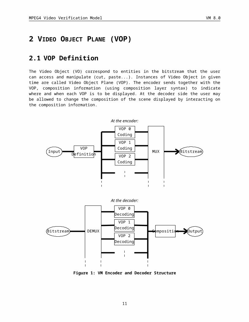
2.1 VOP DefinitionThe Video Object (VO) correspond to entities in the bitstream that the user can access and manipulate (cut, paste...). Instances of Video Object in given time are called Video Object Plane (VOP). The encoder sends together with the VOP, composition information (using composition layer syntax) to indicate where and when each VOP is to be displayed. At the decoder side the user may be allowed to change the composition of the scene displayed by interacting on the composition information.
At the encoder:
InputVOP
Definition
VOP 0Coding
VOP 1Coding
VOP 2Coding
MUX Bitstream
At the decoder:
OutputComposition
VOP 0Decoding
VOP 1Decoding
VOP 2Decoding
DEMUXBitstream
Figure 1: VM Encoder and Decoder Structure
The VOP can be a semantic object in the scene : it is made of Y, U, V components plus shape information. In MPEG-4 video test sequences, the VOP were either known by construction of the sequences (hybrid sequences based on blue screen composition or synthetic sequences) or were defined by semi-automatic segmentation. In the first case, the shape information is represented by an 8 bit component, used for composition (see Section ). In the second case, the shape is a binary mask. Both cases are currently considered in the encoding process. The VOP can have arbitrary shape.
10
MPEG4 Video Verification Model VM 8.0
The exact method used to produce the VOP from the video sequences is not described in this document.
When the sequence has only one rectangular VOP of fixed size displayed at fixed interval, it corresponds to the frame-based coding technique.
2.2 VOP format This section describes the input library, the filtering process and the formation of the VOP.
Section describes the test sequences library. Section describes the suggested downsampling process from ITU-R 601 format to SIF, CIF and QCIF formats. In this section, the acronym SIF is used to designate the 352x240 and 352x288 formats at 30 Hz and 25 Hz, respectively, while CIF designates only the 352x288 format at 30 Hz. Section describes the VOP format.
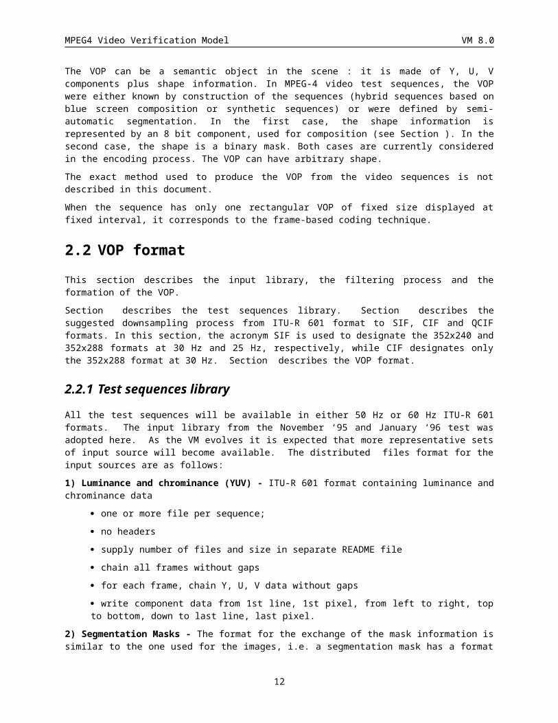
2.2.1 Test sequences libraryAll the test sequences will be available in either 50 Hz or 60 Hz ITU-R 601 formats. The input library from the November ‘95 and January ‘96 test was adopted here. As the VM evolves it is expected that more representative sets of input source will become available. The distributed files format for the input sources are as follows:
1) Luminance and chrominance (YUV) - ITU-R 601 format containing luminance and chrominance data
· one or more file per sequence;
· no headers
· supply number of files and size in separate README file
· chain all frames without gaps
· for each frame, chain Y, U, V data without gaps
· write component data from 1st line, 1st pixel, from left to right, top to bottom, down to last line, last pixel.
2) Segmentation Masks - The format for the exchange of the mask information is similar to the one used for the images, i.e. a segmentation mask has a format similar to ITU-R 601 luminance, where each pixel has a label identifying the region it belongs to (label values are 0,1,2, ...). A segmentation may have a maximum of 256 segments (regions). Whenever possible, the segments should have a semantic meaning and will correspond to the VOP.
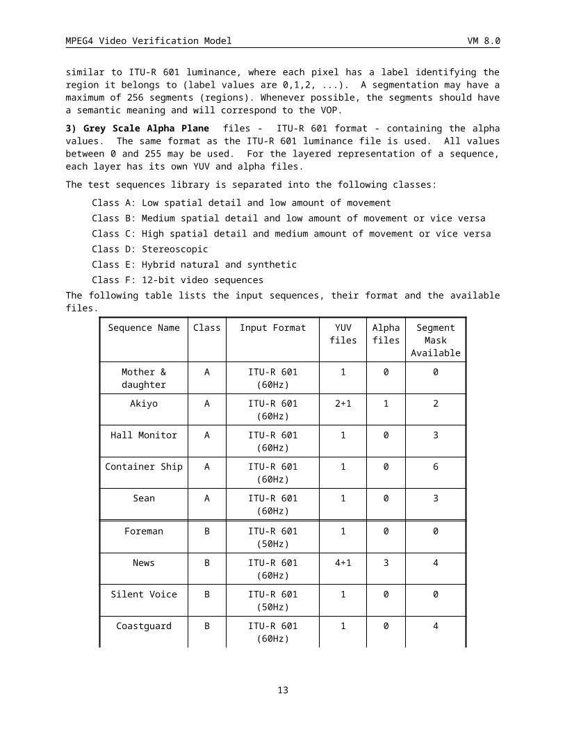
3) Grey Scale Alpha Plane files - ITU-R 601 format - containing the alpha values. The same format as the ITU-R 601 luminance file is used. All values between 0 and 255 may be used. For the layered representation of a sequence, each layer has its own YUV and alpha files.
The test sequences library is separated into the following classes:
Class A: Low spatial detail and low amount of movementClass B: Medium spatial detail and low amount of movement or vice versaClass C: High spatial detail and medium amount of movement or vice versaClass D: StereoscopicClass E: Hybrid natural and syntheticClass F: 12-bit video sequences
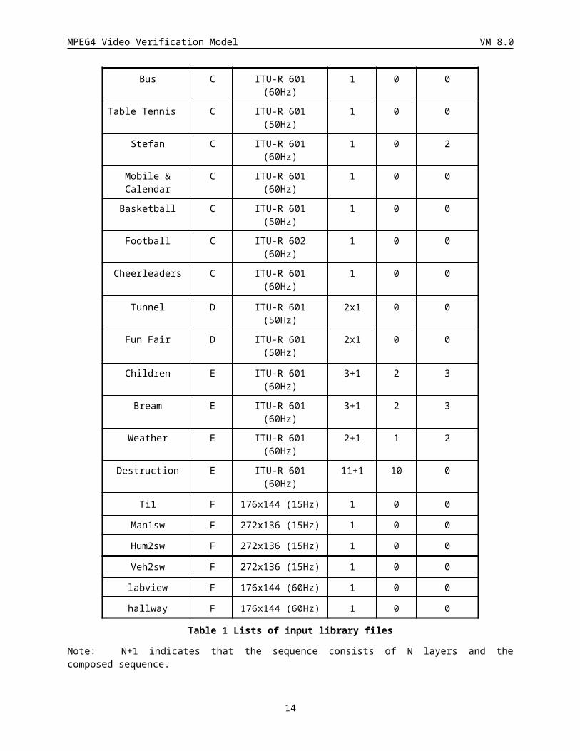
The following table lists the input sequences, their format and the available files.
Sequence Name Class Input Format YUV files
Alpha files
Segment Mask
Available
11
MPEG4 Video Verification Model VM 8.0
Mother & daughter A ITU-R 601 (60Hz) 1 0 0
Akiyo A ITU-R 601 (60Hz) 2+1 1 2
Hall Monitor A ITU-R 601 (60Hz) 1 0 3
Container Ship A ITU-R 601 (60Hz) 1 0 6
Sean A ITU-R 601 (60Hz) 1 0 3
Foreman B ITU-R 601 (50Hz) 1 0 0
News B ITU-R 601 (60Hz) 4+1 3 4
Silent Voice B ITU-R 601 (50Hz) 1 0 0
Coastguard B ITU-R 601 (60Hz) 1 0 4
Bus C ITU-R 601 (60Hz) 1 0 0
Table Tennis C ITU-R 601 (50Hz) 1 0 0
Stefan C ITU-R 601 (60Hz) 1 0 2
Mobile & Calendar C ITU-R 601 (60Hz) 1 0 0
Basketball C ITU-R 601 (50Hz) 1 0 0
Football C ITU-R 602 (60Hz) 1 0 0
Cheerleaders C ITU-R 601 (60Hz) 1 0 0
Tunnel D ITU-R 601 (50Hz) 2x1 0 0
Fun Fair D ITU-R 601 (50Hz) 2x1 0 0
Children E ITU-R 601 (60Hz) 3+1 2 3
Bream E ITU-R 601 (60Hz) 3+1 2 3
Weather E ITU-R 601 (60Hz) 2+1 1 2
Destruction E ITU-R 601 (60Hz) 11+1 10 0
Ti1 F 176x144 (15Hz) 1 0 0
Man1sw F 272x136 (15Hz) 1 0 0
Hum2sw F 272x136 (15Hz) 1 0 0
Veh2sw F 272x136 (15Hz) 1 0 0
labview F 176x144 (60Hz) 1 0 0
hallway F 176x144 (60Hz) 1 0 0
Table 1 Lists of input library files
Note: N+1 indicates that the sequence consists of N layers and the composed sequence.
Nx1 indicates the the sequences consists of N views.
Extension to higher than 8 bit video
In meeting the surveillance applications envisaged for MPEG 4, it is necessary to be able to code efficiently video from a range of sensors. Many of these sensors generate video that does not conform to the traditional digital video formats, in which each pixel comprises a luminance component and two chrominance components, each of
12
MPEG4 Video Verification Model VM 8.0
which is represented with a precision of 8 bits. Many surveillance sensors, such as a range of commercially available thermal imaging sysems, generate digital video that is represented with a precision of up to 12 bits. Often, this video contains only a luminance component.
It is often necessary to display 12-bit video on systems that have only a dynamic range of 8 bits. It has been found that the following methods are useful:
1. truncation of each pixel of 12-bit video to 8-bits,
2. a linear mappping of the full range of pixel values present in a picture or sequence to the range 0 - 255, and
3. a linear mapping of some part of the range of pixel values present in a picture or sequence to 0 - 255, with all pixels outside below this range being mapped to zero and all those above to 255.
In moving from traditional video formats to coding video from these surveillance sensors, a number of changes are required in both encoders and decoders. The changes required in the encoder definition can be summarized as follows:
· definition of a data format for video with more than 8 bits per pixel
· redefinition of certain thresholds used in mode decisions (e. g. the inter / intra decision)
The changes required in the syntax and decoder definition can be summarized as follows:
· addition of a field to indicate the pixel depth,
· changing the size in bits of the transmitted quantizer parameter such that it depends on the pixel depth,
· extension of tables for intra DC prediction to allow larger prediction ifferences to be transmitted.
Even though it is possible that coding of 12-bit video will result in the generation of DCT frequency coefficients that lie outside the range of coefficients that can be represented using current VLC tables, this has not been observed to be a problem, and hence these tables remain unchanged.
Other features of the current VM, such as scalability, are not directly effected.
Test sequences for n-bit coding with n>8 are luminance only, and use two bytes for each pixel value. The least significant n bits contain the luminance value for the pixel. Sequences may be provided with any frame size. The frame height and width is specified in the README file. Alpha files and segmentation masks have the same format as for conventional video.
A range of sequences is used for evaluating 12-bit video. They are reported in Table 1 as class F sequences.
2.2.2 Filtering processThe filtering process for YUV is based on the document [MPEG95/0322] . The filtering process for alpha planes (A) is based on the document [MPEG95/0393]. Software for performing the filtering process was distributed and can also be obtained from MPEG ftp site 'drop.chips.ibm.com:Tampere/Contrib/m0896.zip'.
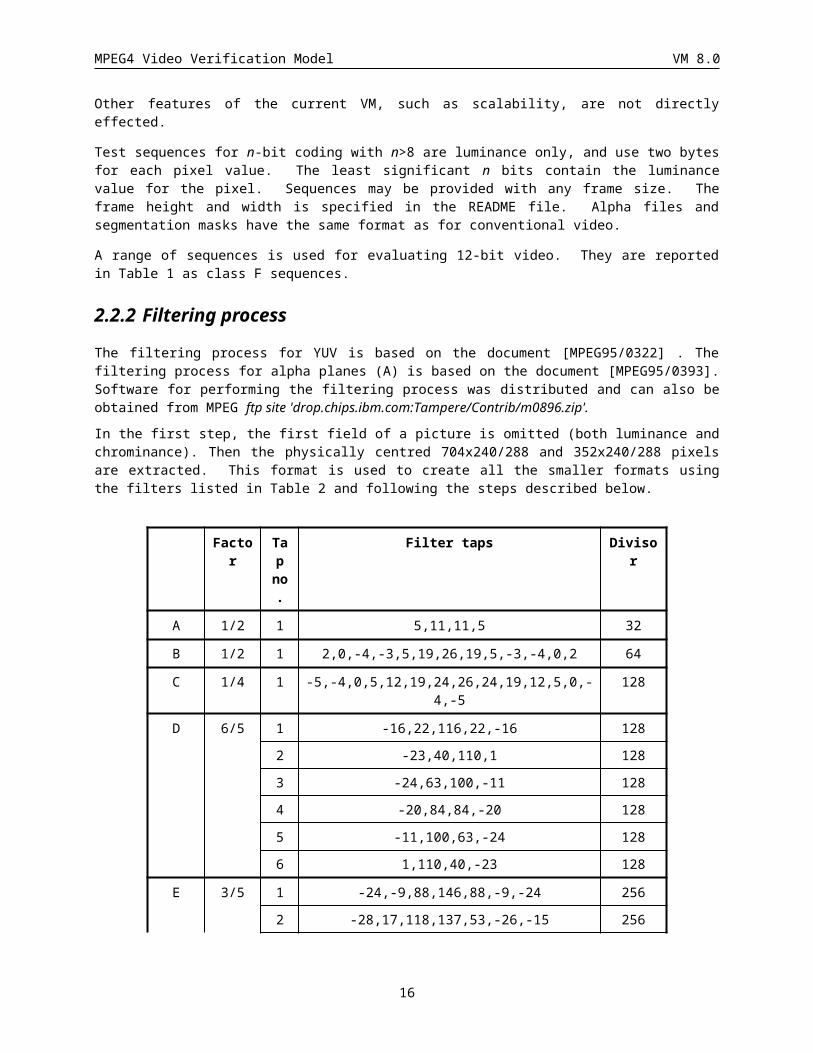
In the first step, the first field of a picture is omitted (both luminance and chrominance). Then the physically centred 704x240/288 and 352x240/288 pixels are extracted. This format is used to create all the smaller formats using the filters listed in Table 2 and following the steps described below.
Factor Tap no.
Filter taps Divisor
A 1/2 1 5,11,11,5 32
13
MPEG4 Video Verification Model VM 8.0
B 1/2 1 2,0,-4,-3,5,19,26,19,5,-3,-4,0,2 64
C 1/4 1 -5,-4,0,5,12,19,24,26,24,19,12,5,0,-4,-5 128
D 6/5 1 -16,22,116,22,-16 128
2 -23,40,110,1 128
3 -24,63,100,-11 128
4 -20,84,84,-20 128
5 -11,100,63,-24 128
6 1,110,40,-23 128
E 3/5 1 -24,-9,88,146,88,-9,-24 256
2 -28,17,118,137,53,-26,-15 256
3 -15,-26,53,137,118,17,-28 256
F 1/2 1 -12, 0, 140, 256, 140, 0, -12 512
Table 2 Filter taps for downsampling
ITU-R 601 to CIF / SIF
For Y
704x240 - B -> 352x240 - D -> 352x288
704x288 - B -> 352x288
For U and V
352x240 - B -> 176x240 - D -> 176x288 - A -> 176x144
352x288 - B -> 176x288 - A -> 176x144
For A
704x240 - F -> 352x240 - D -> 352x288
704x288 - F -> 352x288
ITU-R 601 to QCIF
For Y and A
704x240 - C -> 176x240 - E -> 176x144
704x288 - C -> 176x288 - B -> 176x144
For U and V
352x240 - C -> 88x240 - E -> 88x144 - A -> 88x72
352x288 - C -> 88x288 - B -> 88x144 - A -> 88x72
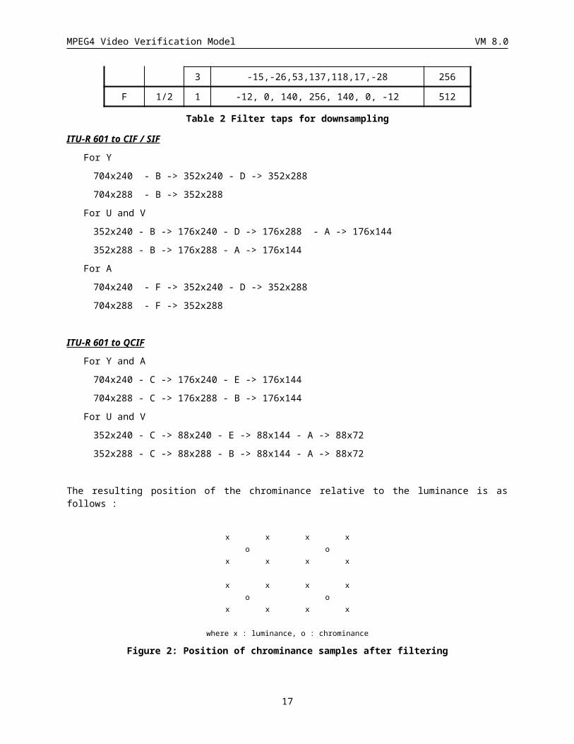
The resulting position of the chrominance relative to the luminance is as follows :
x x x xo o
x x x x
14
MPEG4 Video Verification Model VM 8.0
x x x xo o
x x x x
where x : luminance, o : chrominance
Figure 2: Position of chrominance samples after filtering
Notes: The 4:2:2 to 4:2:0 conversion is done in the last step because then the correct position of the chroma samples can be preserved.
For input sequences in 4:2:0 format a conversion from 4:2:0 to 4:2:2 is performed before the filtering process starts. The interpolation filter is (1,3,3,1) as specified in document [WG11/N0999].
Filtering of border pixels: When some of the filter taps fall outside the active picture area then the edge pixel is repeated into the blanking area.
All test sequences of class F are coded at the same resolution as they are supplied. Hence, the filters specified for downsampling in this section are not required.
2.2.2.1 Processing of grey scale alpha planesThe downsampling process for alpha planes is the same as for luminance (Y). However, for alpha planes a different filter is used for horizontal 2-to-1 filtering. This filter preserves more the high frequency band and therefore maintains a sharp edge for alpha planes.
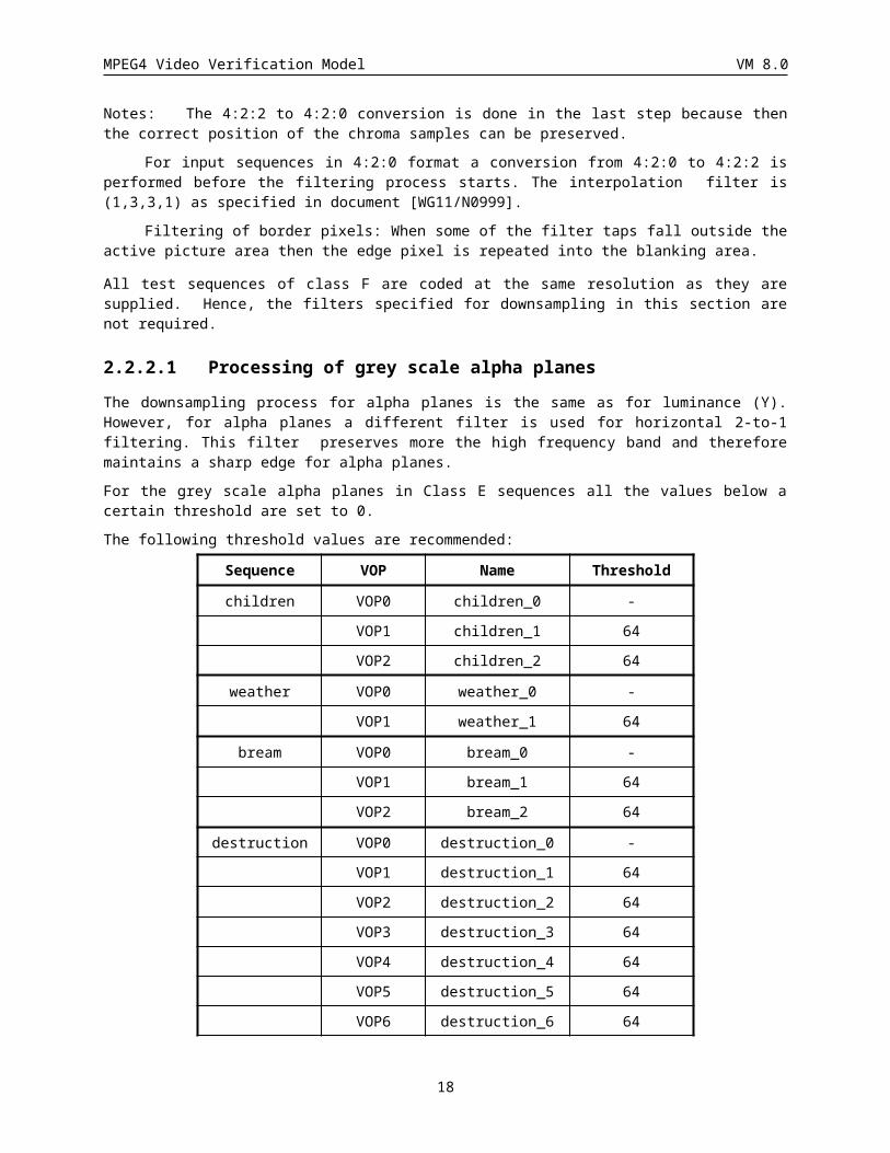
For the grey scale alpha planes in Class E sequences all the values below a certain threshold are set to 0.
The following threshold values are recommended:
Sequence VOP Name Threshold
children VOP0 children_0 -
VOP1 children_1 64
VOP2 children_2 64
weather VOP0 weather_0 -
VOP1 weather_1 64
bream VOP0 bream_0 -
VOP1 bream_1 64
VOP2 bream_2 64
destruction VOP0 destruction_0 -
VOP1 destruction_1 64
VOP2 destruction_2 64
VOP3 destruction_3 64
VOP4 destruction_4 64
VOP5 destruction_5 64
VOP6 destruction_6 64
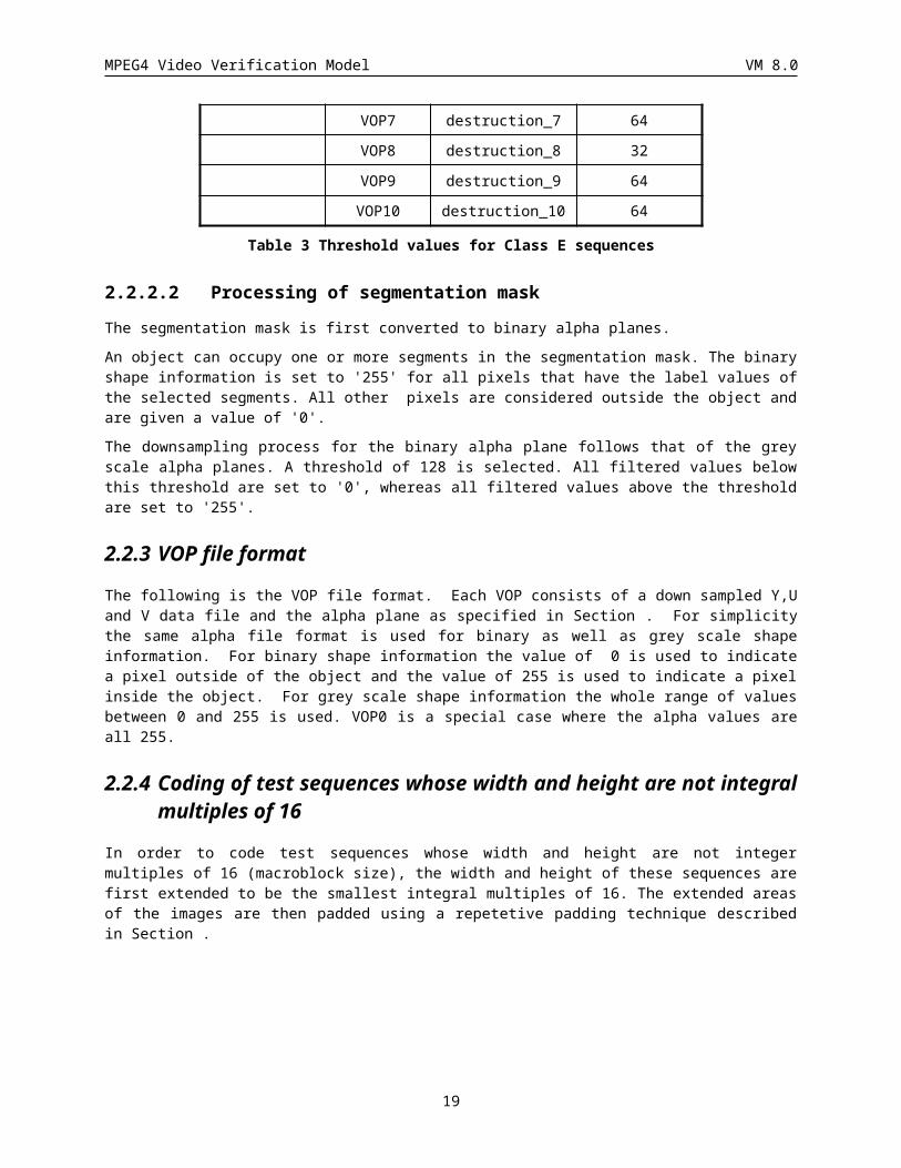
VOP7 destruction_7 64
VOP8 destruction_8 32
15
MPEG4 Video Verification Model VM 8.0
VOP9 destruction_9 64
VOP10 destruction_10 64
Table 3 Threshold values for Class E sequences
2.2.2.2 Processing of segmentation maskThe segmentation mask is first converted to binary alpha planes.
An object can occupy one or more segments in the segmentation mask. The binary shape information is set to '255' for all pixels that have the label values of the selected segments. All other pixels are considered outside the object and are given a value of '0'.
The downsampling process for the binary alpha plane follows that of the grey scale alpha planes. A threshold of 128 is selected. All filtered values below this threshold are set to '0', whereas all filtered values above the threshold are set to '255'.
2.2.3 VOP file formatThe following is the VOP file format. Each VOP consists of a down sampled Y,U and V data file and the alpha plane as specified in Section . For simplicity the same alpha file format is used for binary as well as grey scale shape information. For binary shape information the value of 0 is used to indicate a pixel outside of the object and the value of 255 is used to indicate a pixel inside the object. For grey scale shape information the whole range of values between 0 and 255 is used. VOP0 is a special case where the alpha values are all 255.
2.2.4 Coding of test sequences whose width and height are not integral multiples of 16
In order to code test sequences whose width and height are not integer multiples of 16 (macroblock size), the width and height of these sequences are first extended to be the smallest integral multiples of 16. The extended areas of the images are then padded using a repetetive padding technique described in Section .
16
MPEG4 Video Verification Model VM 8.0
3 ENCODER DEFINITION
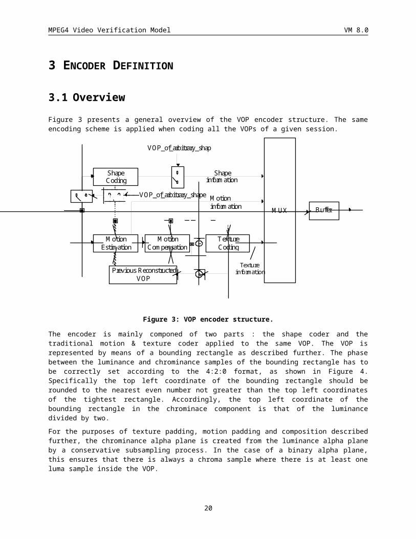
3.1 Overview Figure 3 presents a general overview of the VOP encoder structure. The same encoding scheme is applied when coding all the VOPs of a given session.
MUX Buffer
Previous ReconstructedVOP
Shapeinformation
ShapeCoding
MotionEstimation
MotionCompensation
TextureCoding–
Motioninformation
+Texture
information
VOP_of_arbitrary_shape
VOP_of_arbitrary_shape
Figure 3: VOP encoder structure.
The encoder is mainly componed of two parts : the shape coder and the traditional motion & texture coder applied to the same VOP. The VOP is represented by means of a bounding rectangle as described further. The phase between the luminance and chrominance samples of the bounding rectangle has to be correctly set according to the 4:2:0 format, as shown in Figure 4. Specifically the top left coordinate of the bounding rectangle should be rounded to the nearest even number not greater than the top left coordinates of the tightest rectangle. Accordingly, the top left coordinate of the bounding rectangle in the chrominace component is that of the luminance divided by two.
For the purposes of texture padding, motion padding and composition described further, the chrominance alpha plane is created from the luminance alpha plane by a conservative subsampling process. In the case of a binary alpha plane, this ensures that there is always a chroma sample where there is at least one luma sample inside the VOP.
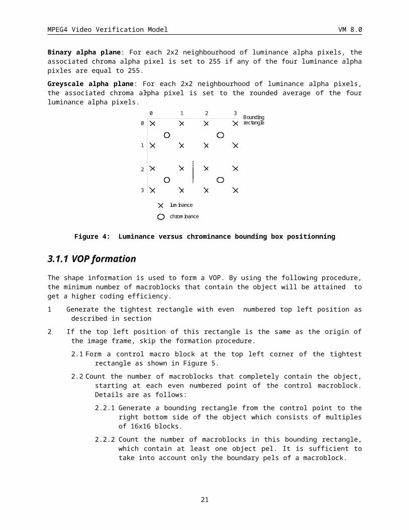
Binary alpha plane: For each 2x2 neighbourhood of luminance alpha pixels, the associated chroma alpha pixel is set to 255 if any of the four luminance alpha pixles are equal to 255.
Greyscale alpha plane: For each 2x2 neighbourhood of luminance alpha pixels, the associated chroma alpha pixel is set to the rounded average of the four luminance alpha pixels.”
17
MPEG4 Video Verification Model VM 8.0
0 1 2 3
0
1
2
3
Boundingrectangle
luminance
chrominance
Figure 4: Luminance versus chrominance bounding box positionning
3.1.1 VOP formation The shape information is used to form a VOP. By using the following procedure, the minimum number of macroblocks that contain the object will be attained to get a higher coding efficiency.
1 Generate the tightest rectangle with even numbered top left position as described in section
2 If the top left position of this rectangle is the same as the origin of the image frame, skip the formation procedure.
2.1 Form a control macro block at the top left corner of the tightest rectangle as shown in Figure 5.
2.2 Count the number of macroblocks that completely contain the object, starting at each even numbered point of the control macroblock. Details are as follows:
2.2.1 Generate a bounding rectangle from the control point to the right bottom side of the object which consists of multiples of 16x16 blocks.
2.2.2 Count the number of macroblocks in this bounding rectangle, which contain at least one object pel. It is sufficient to take into account only the boundary pels of a macroblock.
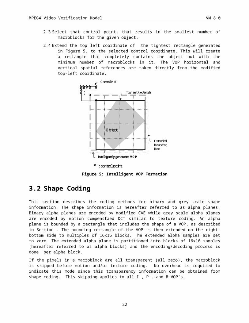
2.3 Select that control point, that results in the smallest number of macroblocks for the given object.
2.4 Extend the top left coordinate of the tightest rectangle generated in Figure 5. to the selected control coordinate. This will create a rectangle that completely contains the object but with the minimum number of macroblocks in it. The VOP horizontal and vertical spatial references are taken directly from the modified top-left coordinate.
18
MPEG4 Video Verification Model VM 8.0
...
Control MB
Tightest Rectangle
ExtendedBoundingBox
Intelligently generated VOP
: control point
...
Object
Figure 5: Intelligent VOP Formation
3.2 Shape Coding This section describes the coding methods for binary and grey scale shape information. The shape information is hereafter referred to as alpha planes. Binary alpha planes are encoded by modified CAE while grey scale alpha planes are encoded by motion compenstaed DCT similar to texture coding. An alpha plane is bounded by a rectangle that includes the shape of a VOP, as described in Section . The bounding rectangle of the VOP is then extended on the right-bottom side to multiples of 16x16 blocks. The extended alpha samples are set to zero. The extended alpha plane is partitioned into blocks of 16x16 samples (hereafter referred to as alpha blocks) and the encoding/decoding process is done per alpha block.
If the pixels in a macroblock are all transparent (all zero), the macroblock is skipped before motion and/or texture coding. No overhead is required to indicate this mode since this transparency information can be obtained from shape coding. This skipping applies to all I-, P-. and B-VOP’s.
3.2.1 OverviewThis section describes the methods by which binary alpha planes are encoded. A binary alpha plane can be encoded in INTRA mode for I-VOPs and in INTER mode for P-VOPs and B-VOPs. The methods used are based on binary alpha blocks and the principal methods are block-based context-based arithmetic encoding and block-based motion compensation.
3.2.2 AbbreviationsBAB Binary Alpha Block
CAE Content-based Arithmetic Encoding
BAC Binary Arithmetic Code
CR The Conversion Ratio
MVPs Motion Vector Prediction for shape
MVDs Motion Vector Difference for shape
19
MPEG4 Video Verification Model VM 8.0
4x4 sub-blocks Elementary block of subdivided BAB.
AlphaTH A threshold used when comparing two 4x4 sub-blocks.
3.2.3 Mode DecisionThis section describes how to decide upon a suitable coding mode for each BAB in the binary alpha map.
3.2.3.1 BAB Accepted Quality (ACQ)In several areas of the mode decision, it is necessary to ascertain whether a BAB has an accepted quality under some specified lossy coding conditions. This section defines the criterion for ‘accepted quality’.
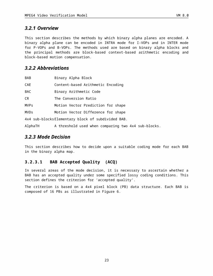
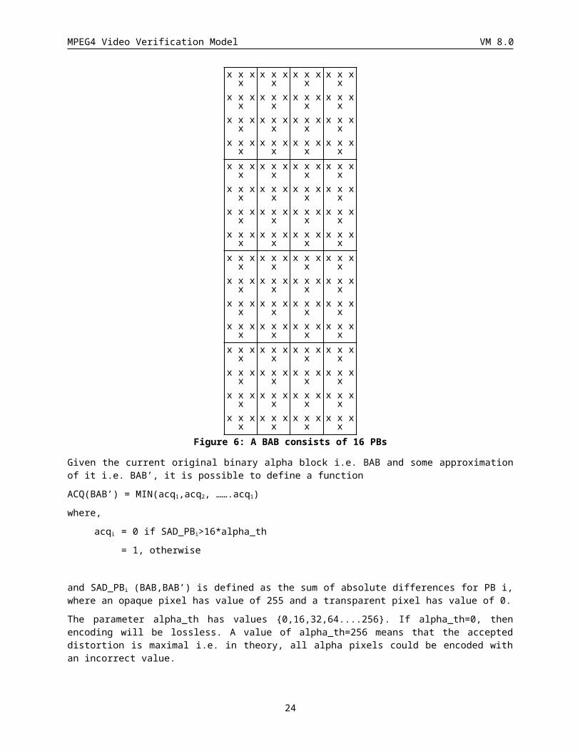
The criterion is based on a 4x4 pixel block (PB) data structure. Each BAB is composed of 16 PBs as illustrated in Figure 6.
Figure 6: A BAB consists of 16 PBs
Given the current original binary alpha block i.e. BAB and some approximation of it i.e. BAB’, it is possible to define a function
ACQ(BAB’) = MIN(acq1,acq2, …….acq1)
where,
acqi = 0 if SAD_PBi>16*alpha_th
= 1, otherwise
and SAD_PBi (BAB,BAB’) is defined as the sum of absolute differences for PB i, where an opaque pixel has value of 255 and a transparent pixel has value of 0.
The parameter alpha_th has values {0,16,32,64....256}. If alpha_th=0, then encoding will be lossless. A value of alpha_th=256 means that the accepted distortion is maximal i.e. in theory, all alpha pixels could be encoded with an incorrect value.
20
x x x xx x x xx x x xx x x x
x x x xx x x xx x x xx x x x
x x x xx x x xx x x xx x x x
x x x xx x x xx x x xx x x x
x x x xx x x xx x x xx x x x
x x x xx x x xx x x xx x x x
x x x xx x x xx x x xx x x x
x x x xx x x xx x x xx x x x
x x x xx x x xx x x xx x x x
x x x xx x x xx x x xx x x x
x x x xx x x xx x x xx x x x
x x x xx x x xx x x xx x x x
x x x xx x x xx x x xx x x x
x x x xx x x xx x x xx x x x
x x x xx x x xx x x xx x x x
x x x xx x x xx x x xx x x x
MPEG4 Video Verification Model VM 8.0
3.2.3.2 BAB Coding ModesEach BAB is coded according to one of seven different modes listed below.
1. MVDs==0 && No Update
2. MVDs!=0 && No Update
3. all_0
4. all_255
5. intraCAE
6. MVDs==0 && interCAE
7. MVDs!=0 && interCAE
· MVDs stands for motion vector difference of shape (see section XXX)
· In I-VOP, only the coding modes “all_0”, “all_255” and “intraCAE” are allowed.
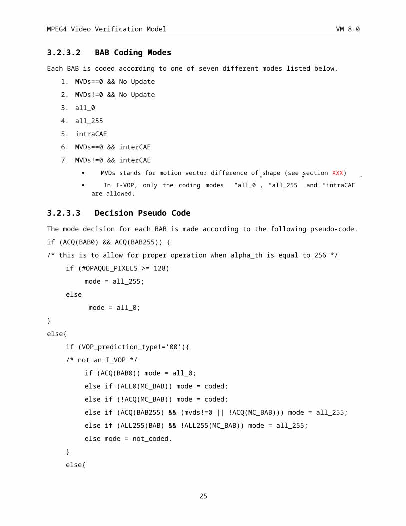
3.2.3.3 Decision Pseudo CodeThe mode decision for each BAB is made according to the following pseudo-code.
if (ACQ(BAB0) && ACQ(BAB255)) {
/* this is to allow for proper operation when alpha_th is equal to 256 */
if (#OPAQUE_PIXELS >= 128)
mode = all_255;
else
mode = all_0;
}
else{
if (VOP_prediction_type!=’00’){
/* not an I_VOP */
if (ACQ(BAB0)) mode = all_0;
else if (ALL0(MC_BAB)) mode = coded;
else if (!ACQ(MC_BAB)) mode = coded;
else if (ACQ(BAB255) && (mvds!=0 || !ACQ(MC_BAB))) mode = all_255;
else if (ALL255(BAB) && !ALL255(MC_BAB)) mode = all_255;
else mode = not_coded.
}
else{
if (ACQ(BAB0)) mode = all_0;
else (ACQ(BAB255)) mode = all_255;
else mode = coded;
}
}
21
MPEG4 Video Verification Model VM 8.0
Notes: ACQ(BABX) means that BABX has an accepted quality.
ALL0(BABX) means that BABX is all0.
ALL255(BABX) means that BABX is all255.
BAB0 is a BAB containing only zero-valued pixels.
BAB255 is a BAB containing only 255-valued pixels.
Mode = coded means that intraCAE or interCAE (in the case of P/B VOPs) is used.
Mode = not_coded means that ‘MVDs==0 && No Update’ or ‘MVDs!=0 && No Update’ is used.
3.2.4 Motion estimation and compensation
3.2.4.1 OverViewVOP level size conversion is carried out before motion estimation (ME) and motion compensation (MC).
MVs (Motion Vector of shape) is used for MC of shape.
Overlapped MC, half sample MC and 8x8 MC are not carried out.
In the case that the region outside VOP is referred, the value for it is set to 0.
For B-VOPs, forward MC is used and neither backward MC nor interpolated MC is used.
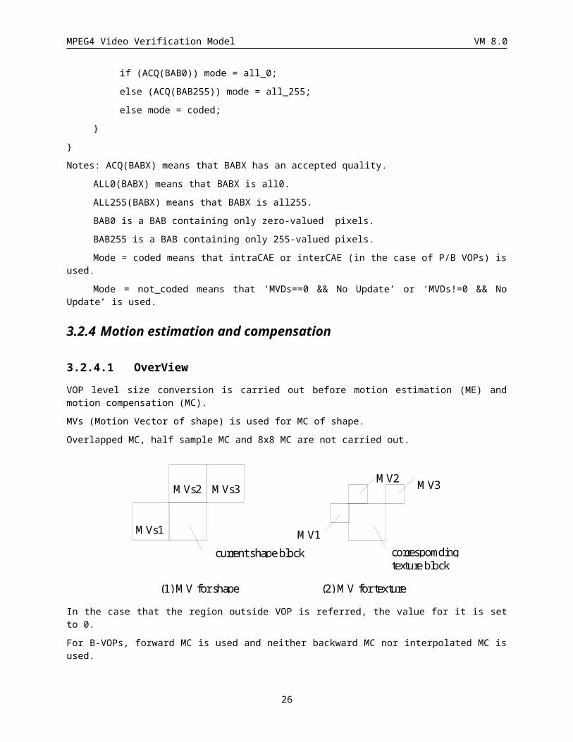
Figure 7: Candidates for MVPs
3.2.4.2 Motion Estimation(ME)The procedure of ME consists of two steps: first to determine MVPs and then to compute MVs accordingly.
3.2.4.2.1 Motion Vector Predictor for shape (MVPs)
MVPs is determined by referring certain candidate MV of shape (MVs) and MV of texture around the MB corresponding to the current shape block. They are located and denoted as shown in Figure 7 where MV1, MV2 and MV3 are rounded to integer. By looking into MVs1, MVs2, MVs3, MV1, MV2 and MV3 in this order, MVPs is determined by taking the first encountered MV that is valid. If no candidate MV is valid, MVPs is regarded as 0.
In the case that separate_motion_shape_texture is ‘1’ or VOP_prediction_type indicates B-VOP or VOP_CR is ½, MVPs is determined only considering MV of shape (MVs1, MVs2 and MVs3) as the candidates.
22
MVs1
MVs2 MVs3
current shape block correspomdingtexture block
MV1
MV3MV2
(1) MV for shape (2) MV for texture
MPEG4 Video Verification Model VM 8.0
3.2.4.2.2 Detection of MV for shape(MVs)
Based on MVPs determined above, MVs is computed by the following procedure.
· The MC error is computed by comparing the BAB indicated by the MVPs and current BAB. If the computed MC error is less or equal to 16xAlphaTH for any 4x4 sub-blocks, the MVPs is directly employed as MVs, and the procedure terminates.
· If the above condition is not satisfied, MV is searched around the prediction vector MVPs while computing 16x16 MC error (SADs) by comparing the BAB indicated by the MV and current BAB. The search range is +/- 16 pixels around MVPs along both horizontal and vertical directions. The MV that minimizes the SADs is taken as MVs and this is further interpreted as MV Difference for shape (MVDs), i.e. MVDs=MVs-MVPs.
· Note the following procedures in special occasions in the search.
1. If more than one MVs minimize SADs by an identical value, the MVDs that minimizes the Q, the code length of MVDs (see below), is selected.
2. If more than one MVs minimize SADs by an identical value with an identical Q, MVDs with smaller vertical element is selected. If the vertical elements are also the same, MVDs with smaller horizontal element is selected.
Q = 2x(Absolute value of MVDs in the horizontal direction)
+ 2x(Absolute value of MVDs in the vertical direction)
+ 2-(One bit) where
One bit = 1 (Horizontal element of MVDs is 0),
One bit = 0 (Otherwise).
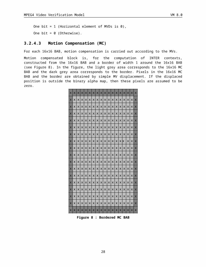
3.2.4.3 Motion Compensation (MC)For each 16x16 BAB, motion compensation is carried out according to the MVs.
Motion compensated block is, for the computation of INTER contexts, constructed from the 16x16 BAB and a border of width 1 around the 16x16 BAB (see Figure 8). In the figure, the light grey area corresponds to the 16x16 MC BAB and the dark grey area corresponds to the border. Pixels in the 16x16 MC BAB and the border are obtained by simple MV displacement. If the displaced position is outside the binary alpha map, then these pixels are assumed to be zero.
x x x x x x x x x x x x x x x x x x
x x x x x x x x x x x x x x x x x x
x x x x x x x x x x x x x x x x x x
x x x x x x x x x x x x x x x x x x
x x x x x x x x x x x x x x x x x x
x x x x x x x x x x x x x x x x x x
x x x x x x x x x x x x x x x x x x
23
MPEG4 Video Verification Model VM 8.0
x x x x x x x x x x x x x x x x x x
x x x x x x x x x x x x x x x x x x
x x x x x x x x x x x x x x x x x x
x x x x x x x x x x x x x x x x x x
x x x x x x x x x x x x x x x x x x
x x x x x x x x x x x x x x x x x x
x x x x x x x x x x x x x x x x x x
x x x x x x x x x x x x x x x x x x
x x x x x x x x x x x x x x x x x x
x x x x x x x x x x x x x x x x x x
x x x x x x x x x x x x x x x x x x
Figure 8 : Bordered MC BAB
3.2.5 Size conversion (Rate control)Rate control and rate reduction is realized through size-conversion of the binary alpha information. The size conversion process consists of the following two steps.
3.2.5.1 VOP level size conversion The size conversion ratio is indicated by VOP_CR which takes either 1 or 1/2. When VOP_CR is 1/2, the size-conversion is carried out at VOP level. The original bounding box (section ) of the binary alpha information is extended to multiples of 16/VOP_CR. The extended alpha values are set to zero.
3.2.5.1.1 Down-samplingThe extended shape bounding box is divided into square blocks of (16/VOP_CR) pixels. And each square block is size-converted using the same down-sampling method as in the block level size conversion method.
3.2.5.1.2 Shape codingThe down sampled shape is divided into 16x16 samples BABs. Each down-sampled 16x16 BAB is coded by block based shape coding method. It means that if AlphaTH is greater than zero and CR is decided to 1/2, 16x16 down-sampled BAB is down-sampled again.
In the case that VOP_CR = 1/2, the local decoded shape which is size-converted at VOP level is stored in the frame memory of the shape frame. For the shape motion estimation and compensation, if VOP_CR of reference shape VOP is not equal to that of current shape VOP, the reference shape frame (not VOP) is size-converted corresponding to the current shape VOP.
For P-VOPs, the following procedures are carried out if VOP_CR = 1/2.
· The components of shape motion vector are measured on the down sampled shape frame.
· MVPs is calculated only using shape motion vector, MVs1, MVs2 and MVs3.
· Search range of shape motion vector is +/- 16 samples around MVPs.
24
MPEG4 Video Verification Model VM 8.0
3.2.5.1.3 Up-samplingEach 16x16 sampled BAB is size converted using the same up-sampling process as in the block level size conversion method (section ). The process of up-sampling is carried out so that the size-converted shape can be utilized for the texture coding.
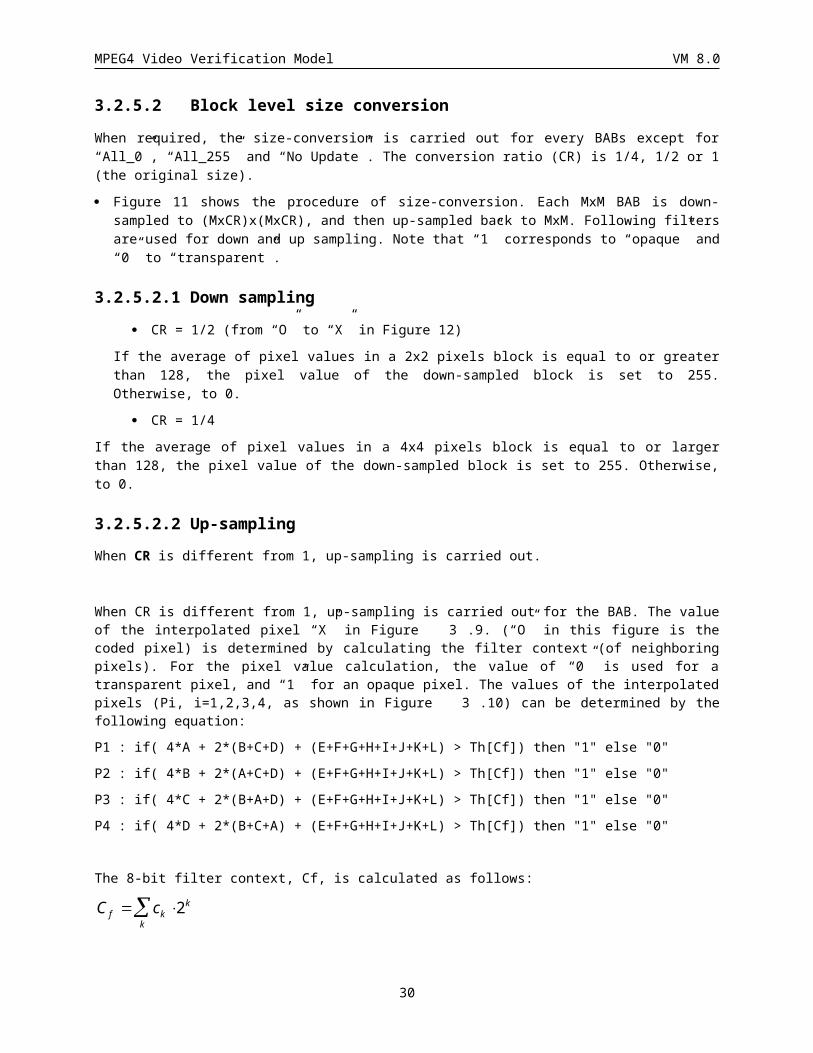
3.2.5.2 Block level size conversion
When required, the size-conversion is carried out for every BABs except for “All_0”, “All_255” and “No Update”. The conversion ratio (CR) is 1/4, 1/2 or 1 (the original size).
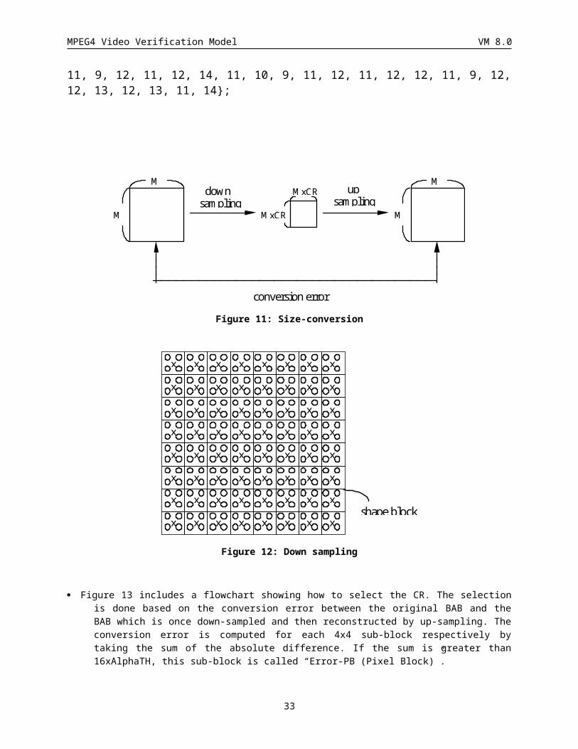
· Figure 11 shows the procedure of size-conversion. Each MxM BAB is down-sampled to (MxCR)x(MxCR), and then up-sampled back to MxM. Following filters are used for down and up sampling. Note that “1” corresponds to “opaque” and “0” to “transparent”.
3.2.5.2.1 Down sampling
· CR = 1/2 (from “O” to “X” in Figure 12)
If the average of pixel values in a 2x2 pixels block is equal to or greater than 128, the pixel value of the down-sampled block is set to 255. Otherwise, to 0.
· CR = 1/4
If the average of pixel values in a 4x4 pixels block is equal to or larger than 128, the pixel value of the down-sampled block is set to 255. Otherwise, to 0.
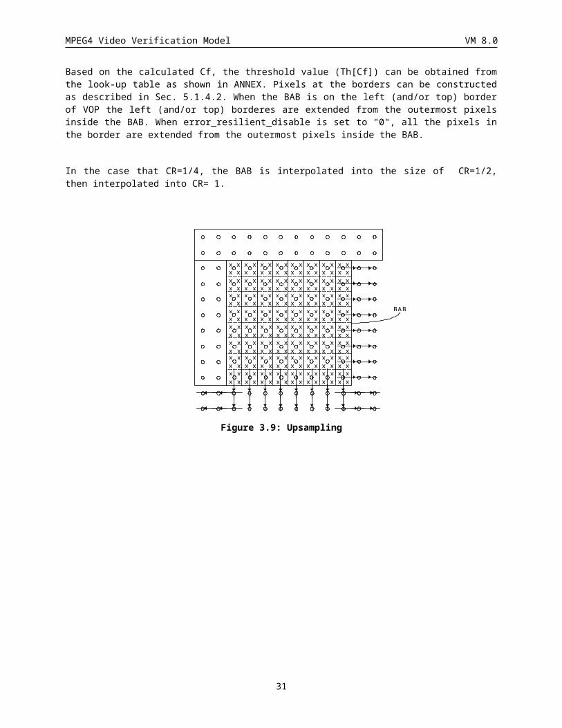
3.2.5.2.2 Up-samplingWhen CR is different from 1, up-sampling is carried out.
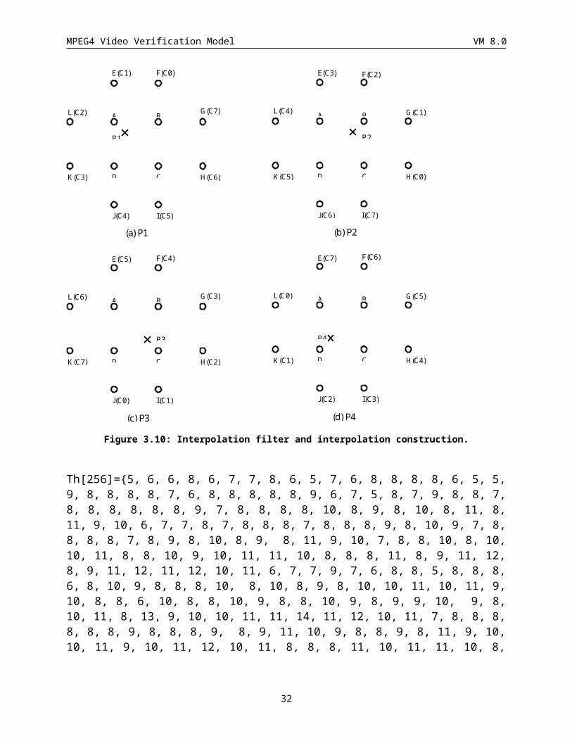
When CR is different from 1, up-sampling is carried out for the BAB. The value of the interpolated pixel “X” in Figure 3.9. (“O” in this figure is the coded pixel) is determined by calculating the filter context (of neighboring pixels). For the pixel value calculation, the value of “0” is used for a transparent pixel, and “1” for an opaque pixel. The values of the interpolated pixels (Pi, i=1,2,3,4, as shown in Figure 3.10) can be determined by the following equation:
P1 : if( 4*A + 2*(B+C+D) + (E+F+G+H+I+J+K+L) > Th[Cf]) then "1" else "0"
P2 : if( 4*B + 2*(A+C+D) + (E+F+G+H+I+J+K+L) > Th[Cf]) then "1" else "0"
P3 : if( 4*C + 2*(B+A+D) + (E+F+G+H+I+J+K+L) > Th[Cf]) then "1" else "0"
P4 : if( 4*D + 2*(B+C+A) + (E+F+G+H+I+J+K+L) > Th[Cf]) then "1" else "0"
The 8-bit filter context, Cf, is calculated as follows:
C cf kk
k 2
Based on the calculated Cf, the threshold value (Th[Cf]) can be obtained from the look-up table as shown in ANNEX. Pixels at the borders can be constructed as described in Sec. 5.1.4.2. When the BAB is on the left (and/or top) border of VOP the left (and/or top) borderes are extended from the outermost pixels inside the BAB. When error_resilient_disable is set to "0", all the pixels in the border are extended from the outermost pixels inside the BAB.
25
MPEG4 Video Verification Model VM 8.0
In the case that CR=1/4, the BAB is interpolated into the size of CR=1/2, then interpolated into CR= 1.
xxxx
xxxx
xxxx
xxxx
xxxx
xxxx
xxxx
xxxx
xxxx
xxxx
xxxx
xxxx
xxxx
xxxx
xxxx
xxxx
xxxx
xxxx
xxxx
xxxx
xxxx
xxxx
xxxx
xxxx
xxxx
xxxx
xxxx
xxxx
xxxx
xxxx
xxxx
xxxx
xxxx
xxxx
xxxx
xxxx
xxxx
xxxx
xxxx
xxxx
xxxx
xxxx
xxxx
xxxx
xxxx
xxxx
xxxx
xxxx
xxxx
xxxx
xxxx
xxxx
xxxx
xxxx
xxxx
xxxx
xxxx
xxxx
xxxx
xxxx
xxxx
xxxx
xxxx
xxxx
BAB
Figure 3.9: Upsampling
26
MPEG4 Video Verification Model VM 8.0
A B
D C
E(C1) F(C0)
G(C7)
H(C6)
I(C5)J(C4)
K(C3)
L(C2)
P1
A B
D C
E(C3) F(C2)
G(C1)
H(C0)
I(C7)J(C6)
K(C5)
L(C4)
P2
A B
D C
E(C7) F(C6)
G(C5)
H(C4)
I(C3)J(C2)
K(C1)
L(C0)
P4
A B
D C
E(C5) F(C4)
G(C3)
H(C2)
I(C1)J(C0)
K(C7)
L(C6)
P3
(a) P1 (b) P2
(c) P3 (d) P4
Figure 3.10: Interpolation filter and interpolation construction.
Th[256]={5, 6, 6, 8, 6, 7, 7, 8, 6, 5, 7, 6, 8, 8, 8, 8, 6, 5, 5, 9, 8, 8, 8, 8, 7, 6, 8, 8, 8, 8, 8, 9, 6, 7, 5, 8, 7, 9, 8, 8, 7, 8, 8, 8, 8, 8, 8, 9, 7, 8, 8, 8, 8, 10, 8, 9, 8, 10, 8, 11, 8, 11, 9, 10, 6, 7, 7, 8, 7, 8, 8, 8, 7, 8, 8, 8, 9, 8, 10, 9, 7, 8, 8, 8, 8, 7, 8, 9, 8, 10, 8, 9, 8, 11, 9, 10, 7, 8, 8, 10, 8, 10, 10, 11, 8, 8, 10, 9, 10, 11, 11, 10, 8, 8, 8, 11, 8, 9, 11, 12, 8, 9, 11, 12, 11, 12, 10, 11, 6, 7, 7, 9, 7, 6, 8, 8, 5, 8, 8, 8, 6, 8, 10, 9, 8, 8, 8, 10, 8, 10, 8, 9, 8, 10, 10, 11, 10, 11, 9, 10, 8, 8, 6, 10, 8, 8, 10, 9, 8, 8, 10, 9, 8, 9, 9, 10, 9, 8, 10, 11, 8, 13, 9, 10, 10, 11, 11, 14, 11, 12, 10, 11, 7, 8, 8, 8, 8, 8, 8, 9, 8, 8, 8, 9, 8, 9, 11, 10, 9, 8, 8, 9, 8, 11, 9, 10, 10, 11, 9, 10, 11, 12, 10, 11, 8, 8, 8, 11, 10, 11, 11, 10, 8, 11, 9, 12, 11, 12, 14, 11, 10, 9, 11, 12, 11, 12, 12, 11, 9, 12, 12, 13, 12, 13, 11, 14};
27
MPEG4 Video Verification Model VM 8.0
downsampling
upsampling
MxCR
MxCR
M
M
conversion error
M
M
Figure 11: Size-conversion
x x x x x x x x
x x x x x x x x
x x x x x x x x
x x x x x x x x
x x x x x x x x
x x x x x x x x
x x x x x x x x
x x x x x x x xshape block
Figure 12: Down sampling
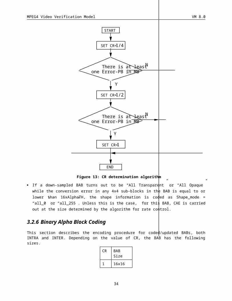
· Figure 13 includes a flowchart showing how to select the CR. The selection is done based on the conversion error between the original BAB and the BAB which is once down-sampled and then reconstructed by up-sampling. The conversion error is computed for each 4x4 sub-block respectively by taking the sum of the absolute difference. If the sum is greater than 16xAlphaTH, this sub-block is called “Error-PB (Pixel Block)”.
28
MPEG4 Video Verification Model VM 8.0
START
N
SET CR=1/4
END
Y
N
Y
SET CR=1
SET CR=1/2
There is at least one Error-PB in MB
There is at least one Error-PB in MB
Figure 13: CR determination algorithm
· If a down-sampled BAB turns out to be “All Transparent” or “All Opaque” while the conversion error in any 4x4 sub-blocks in the BAB is equal to or lower than 16xAlphaTH, the shape information is coded as Shape_mode = “all_0” or “all_255”. Unless this is the case, for this BAB, CAE is carried out at the size determined by the algorithm for rate control.
3.2.6 Binary Alpha Block CodingThis section describes the encoding procedure for coded/updated BABs, both INTRA and INTER. Depending on the value of CR, the BAB has the following sizes.
CR BAB Size
1 16x16
½ 8x8
¼ 4x4
The pixels in the BAB are encoded by context-based arithmetic encoding (CAE). For encoding, the BAB pixels are scanned in raster order. However, the BAB may be transposed before encoding. Furthermore, for P-VOPs, it may be chosen to encode the BAB in INTRA or INTER mode.
29
MPEG4 Video Verification Model VM 8.0
Firstly, the CAE method is detailed for encoding INTRA and INTER BABs and then coding decisions for transposition and INTRA/INTER are outlined.
3.2.6.1 The CAE AlgorithmContext-based arithmetic encoding (CAE) is used to code each binary pixel of the BAB. Prior to coding the first pixel, the arithmetic encoder is initialised. Each binary pixel is then encoded in raster order. The process for encoding a given pixel is the following:
1. Compute a context number.
2. Index a probability table using the context number.
3. Use the indexed probability to drive an arithmetic encoder.
When the final pixel has been processed, the arithmetic code is terminated. The arithmetic encoder and decoder have a 32-bit register and are described in terms of C source functions in section
A coded BAB can be compressed with CAE in INTRA or INTER mode. Both modes result in the generation of a single binary arithmetic codeword (BAC). The various coding modes are characterized by their context computation and the probability table used (see Appendix G).
The following section describes the computation of the contexts for INTRA and INTER modes.
3.2.6.1.1 Contexts for INTRA and INTER CAE
For INTRA coded BABs, a 10 bit context k
kkcC 2 is built for each pixel as illustrated in Figure 14.
C0C1
C6 C5 C4 C3 C2
C9 C8 C7
?
C0
C3 C2 C1
?
C8
C7 C6 C5
C4
Pixels of the curren tBA B
Pixels of the borderedM C BA B
alignmen t
(a) (b)
Figure 14 (a) The INTRA template and context construction. (b) The INTER template and context construction. The pixel to be coded is marked with ‘?’.
For INTER coded BABs, temporal redundancy is exploited by using pixels from the bordered motion compensated
BAB (depicted in Figure 8) to make up part of the context. Specifically, a 9 bit context C ck 2k
k is built as
illustrated in Figure 14.
There are some special cases to note.
·When building contexts, any pixels outside the bounding box of the current VOP to the left and above are assumed to be zero.
·The template may cover pixels from BABs which are not known at decoding time. (Figure 15 illustrates the locations of these pixels.) The values of these unknown pixels is therefore estimated by template padding.
30
MPEG4 Video Verification Model VM 8.0
·When constructing the INTRA context, the following steps are taken in the sequence
1.if (c7 is unknown) c7=c8,
2.if (c3 is unknown) c3=c4,
3.if (c2 is unknown) c2=c3.
·When constructing the INTER context, the following conditional assignment is performed.
if (c1 is unknown) c1=c2
3.2.6.1.2 Bordering of BABsWhen encoding a BAB, pixels from neighbouring BABs can be used to make up the context. For both the INTRA and INTER cases, a border of width equal to 2 about the current BAB is used as depicted in Figure 15. The pixels in the light grey area are part of the BAB to be encoded. The pixels in the dark area are the border pixels. These are obtained from previously encoded and reconstructed BABs except for those marked ‘0’ which are unknown at decoding time.
x x x x x x x x x x x x x x x x x x x x
x x x x x x x x x x x x x x x x x x x x
x x x x x x x x x x x x x x x x x x 0 0
x x x x x x x x x x x x x x x x x x 0 0
x x x x x x x x x x x x x x x x x x 0 0
x x x x x x x x x x x x x x x x x x 0 0
x x x x x x x x x x x x x x x x x x 0 0
x x x x x x x x x x x x x x x x x x 0 0
x x x x x x x x x x x x x x x x x x 0 0
x x x x x x x x x x x x x x x x x x 0 0
x x x x x x x x x x x x x x x x x x 0 0
x x x x x x x x x x x x x x x x x x 0 0
x x x x x x x x x x x x x x x x x x 0 0
x x x x x x x x x x x x x x x x x x 0 0
x x x x x x x x x x x x x x x x x x 0 0
x x x x x x x x x x x x x x x x x x 0 0
x x x x x x x x x x x x x x x x x x 0 0
x x x x x x x x x x x x x x x x x x 0 0
0 0 0 0 0 0 0 0 0 0 0 0 0 0 0 0 0 0 0 0
0 0 0 0 0 0 0 0 0 0 0 0 0 0 0 0 0 0 0 0
Figure 15 Current bordered BAB
3.2.6.1.3 Border SubsamplingIf the value of CR is not equal to 1 then the BAB is subsampled. A subsampling procedure is also applied to the BAB borders for both the current BAB and the motion compensated BAB.
31
MPEG4 Video Verification Model VM 8.0
The border of the current BAB consists of 2 lines of 20 pixels, denoted the TOP_BORDER and 2 columns of 16 pixels, denoted the LEFT_BORDER. Depending on CR, these border areas are subsampled by a factor of N = 1,2,4. The code is as follows where TOP_SUB_BORDER and LEFT_SUB_BORDER represent the subsampled borders.
int TOP_BORDER[2][20], LEFT_BORDER[16][2], TOP_SUB_BORDER[2][4+16/N], LEFT_SUB_BORDER[16/N][2];
int i,j,k,tmp;
TOP_SUB_BORDER[0][0] = TOP_BORDER[0][0];TOP_SUB_BORDER[0][1] = TOP_BORDER[0][1];TOP_SUB_BORDER[1][0] = TOP_BORDER[1][0];TOP_SUB_BORDER[1][1] = TOP_BORDER[1][1];for (j=0;j<2;j++)
for (i=0;i<16/N;i++) {tmp = 0;for (k=0;k<N;k++)
tmp += (TOP_BORDER[j][i*N+k+2]!=0);TOP_SUB_BORDER[j][i+2] = (tmp+N/2)/N;tmp = 0;for (k=0;k<N;k++)
tmp += (LEFT_BORDER[i*N+k][j]!=0);LEFT_SUB_BORDER[i][j] = (tmp+N/2)/N;
}TOP_SUB_BORDER[0][i+2] = TOP_BORDER[0][18];TOP_SUB_BORDER[0][i+3] = TOP_BORDER[0][19];TOP_SUB_BORDER[1][i+2] = TOP_BORDER[1][18];TOP_SUB_BORDER[1][i+3] = TOP_BORDER[1][19];
The border of the motion compensated BAB (see FIG_MC) consists of 2 lines of 16 pixels (TOP and BOTTOM) and 2 columns of 16 pixels (LEFT and RIGHT). The corner pixels are placed directly into the MC_SUB_BORDER, the subsampled border of the motion compensated BAB. The TOP pixels are subsampled as follows where SUB_TOP represents the subsampled line of pixels.
for (i=0;i<16/N;i++) {tmp = 0;for (k=0;k<N;k++)
tmp += (TOP[i*N+k]!=0);SUB_TOP[i] = (tmp+N/2)/N;
}
SUB_BOTTOM, SUB_LEFT and SUB_RIGHT are produced in the same way as SUB_TOP.
3.2.6.1.4 Arithmetic Encoding and Decoding for SC Emulation AvoidanceThe arithmetic encoding and decoding modules contain a mechanism to avoid SC emulation. The mechanism involves monitoring the number of consequtive zero bits being output by the arithmetic encoder. If the number of consequtive zero bits is greater than a given tolerance then a ‘1’ bit is inserted into the bitstream. The tolerances are given below
MAXHEADING MAXMIDDLE MAXTRAILING
8 16 8
The encoder mechanism consists of the following steps:
1. if the first MAXHEADING bits of the stream generated by the arithmetic encoder are '0's, then a '1' is inserted after the MAXHEADING-th '0'.
2. if there is sequence of MAXMIDDLE '0's in the middle of the stream generated by the arithmetic encoder, then a '1' is inserted after the MAXMIDDLE-th '0'.
32
MPEG4 Video Verification Model VM 8.0
3. if the last MAXTRAILING+1 bits of the stream generated by the arithmetic encoder are '0's, then a '1' is appended at the end of the stream.
4. if the stream generated by the arithmetic encoder contains '0's only, then a '1' is appended at the end of the stream
These steps are executed sequentially. The arithmetic decoder is designed to skip the inserted bits. See CAE_SOFT.
3.2.6.2 BAB Encoding DecisionsCoding decisions are made by coding the BAB under all the possible conditions and choosing the coding conditions which yield the lowest code length.
For I-VOPs, the BAB is encoded in the two following ways.
·INTRA
·Transposition of the bordered BAB followed by INTRA
This results in two INTRA binary arithmetic codes and the shortest code is chosen. If the two codes have the same length, then the former is chosen.
In P-VOPs, two more arithmetic codes are produced corresponding to the following coding combinations.
·INTER
·Transposition of the bordered BAB and of the bordered MC-BAB followed by INTER
This results in two INTER binary arithmetic codes and the shortest code is chosen. If the two codes have the same length, then former is chosen.
For P-VOPs, the final step in the decision is to compare the shortest INTRA code with shortest INTER code. For this comparison, it is necessary to add the number of bits for MVDs to the INTER code length. Furthermore, the respective code lengths of the first_shape_code for INTRA and INTER modes are taken into account. The INTER code is chosen if the total INTER code length is smaller than the total INTRA code length for the BAB.
If the selected coding condition involves transposition of the BAB, then ST is set to 1. Otherwise it is set to 0.
3.2.7 Grey Scale Shape Coding
3.2.7.1 support Function And Alpha Values CodingGray-level alpha plane is encoded as its support function and the alpha values on the support. The support function is encoded by binary shape coding as described in Section and the alpha values are encoded as texture with arbitrary shape.
Gray-LevelAlpha
Support Texture
BinaryShape Coder
Texture Coder
33
MPEG4 Video Verification Model VM 8.0
Figure 16 : Gray shape coding
The support is obtained by thresholding the gray-level alpha plane by 0.
The alpha values are partitioned into 16x16 blocks and encoded the same way as the luminance (see Section ). The 16x16 blocks of alpha values are referred to as alpha macroblock hereafter. The encoded data of an alpha macroblock are appended to the end of the corresponding (texture) macroblock, or the encoded macroblock texture in the case of separate motion-texture mode. The formats and syntax of the encoded alpha macroblocks are described in the following.
I-VOP and P-VOP CODA Aacpred_flag CBPA Alpha BlockData
For I-VOP and intra-coded macroblocks in VOP types, CODA is 1 if the alpha values in the gray alpha macroblock are all opaque (255) and 0 otherwise. For inter-coded macroblocks in P-VOP,
if (alpha_residue_all_zero)CODA = 1
else {if (alpha_mb_all_opaque)
CODA = 01else
CODA = 00}
When CODA is 1 or 01, no more data are included in the bitstream. CBPA (Coded block pattern for alpha) is the same as CBPY (See section ). Note that for both I-VOP and P-VOP, the third column of Table 52 is used. Alpha block data format are the same as block data (see section ). Note the alpha macroblocks and blocks with all zero alpha values are not included in the bitstream. All of the rest parameters needed for encoding and decoding of alpha macroblocks are the same as in the texture macroblocks.
B-VOP CODA MODBA CBPBAlpha Block Data
CODA is 1 if the alpha values in the alpha macroblock are all 255 and thus no more data are sent to the bitstream. CODA is 0 otherwise. MODBA has the same meaning as MODB (Seesection ) and CBPBA is similarly defined as CBPB except that it has a maximum of four bits.
3.2.7.2 Feathering and translucency codingFor a large percentage of sequences utilizing grayscale alpha masks, the textures of the alpha masks are relatively simple. One example is a grayscale alpha mask that consists of a constant gray value. Another example is a grayscale alpha mask that consists of a binary alpha mask with the values around the edges tapered from 255 to 0 to provide for a smooth compositing with the background. These types of grayscale alpha masks can be described as a binary mask and a very simple modification to the binary mask.
3.2.7.2.1 Detailed DescriptionThe description of each Video Object Layer will include an identifier to select one of six modes: no effects, linear feathering, constant alpha, linear feathering and constant alpha, feathering filter, or feathering filter and constant alpha. The input for the linear feathering and feathering filter modes can be a sequence of binary or grayscale alpha masks. The input for the constant alpha, linear feathering and constant alpha, and feathering filter and constant alpha modes will be a sequence of grayscale alpha masks. If the mode selected is no effects, the default alpha mask compression algorithm specified will be utilized. The mode will be represented as a 4-bit code, video_object_layer_shape_effects, transmitted as part of the VOL descriptor (see Table 18). Future modes may be adopted and assigned unique 4-bit video_object_layer_shape_effects codes.
34
MPEG4 Video Verification Model VM 8.0
3.2.7.2.1.1 Linear Feathering Mode
If the input is not a binary alpha mask, the input will be converted to a binary alpha mask by thresholding all non-zero values to 255. An integer between 0 and 7 specifying the distance, in pixels, from the edge of the binary mask to feather must be given. The feathering is performed on interior shape pixels within the specified distance of an edge of the mask. This integer is transmitted as part of the VOL descriptor as the 3-bit parameter video_object_layer_feather_dist. The binary alpha mask is compressed using the default algorithm. The decoder reconstructs the complete binary alpha mask and then applies the feathering algorithm to this mask with the number of pixels parameter (video_object_layer_feather_dist). The feathering algorithm tapers the alpha values of the appropriate pixels along the shape boundaries linearly from the opaque alpha value (either 255 or VOP_constant_alpha_value ) to 0.
3.2.7.2.1.2 Feathering Algorithm
Calculate the alpha value for all opaque pixels within distance video_object_layer_feather_dist (the parameter specifying the number of pixels to feather) with:
alpha = distance / (video_object_layer_feather_dist + 1) * opaque_value
where distance is the Euclidean distance measure between the centers of the pixels. opaque_value is the alpha value of opaque pixels in the alpha mask (255 for binary images).
3.2.7.2.1.3 Constant Alpha Mode
Each input grayscale alpha mask is analyzed and categorized as either a Constant Alpha mask or a standard grayscale mask. A mask is considered a Constant Alpha mask if all the non-zero alpha values in the mask are within a specified bound. The 1-bit code, VOP_constant_alpha, selects whether the Constant Alpha effect is on or off. VOP_constant_alpha is set to 1 in the case where the mask is classified as a Constant Alpha mask. Then the average of the non-zero alpha values is taken as the alpha value for the Constant Alpha mask and the one byte VOP_constant_alpha_value is set to this value. The grayscale mask is thresholded and converted to a binary alpha mask which is compressed using the default algorithm. The decoder decodes the binary alpha mask and converts all the opaque pixel alpha values to the transmitted alpha value. If the mask does not qualify as a constant alpha mask, then the 1-bit VOP_constant_alpha value is set to 0 and the mask is compressed with the standard grayscale algorithm. VOP_constant_alpha_value is not transmitted in this case.
3.2.7.2.1.4 Linear Feathering and Constant Alpha Mode
This mode is nearly identical to the Constant Alpha Mode with the exception that, as in the Linear Feathering Mode, the 3-bit parameter specifying the number of pixels over which to feather (video_object_layer_feather_dist), is transmitted as part of the Video Object Layer descriptor. Each input grayscale alpha mask is analyzed and categorized as either a Constant Alpha mask or a standard grayscale mask as described for the Constant Alpha Mode. If a mask is categorized as a Constant Alpha mask, then it is transmitted as described in the Constant Alpha Mode. In the decoder, the binary mask is decoded, the alpha values are converted to VOP_constant_alpha_value, and then the mask is passed to the linear feathering algorithm with the number of pixels to feather parameter. If the mask is labeled as a standard grayscale mask, then the 1-bit VOP_constant_alpha value is set to 0 and it is compressed with the default grayscale alpha mask compression algorithm, but it is not feathered.
3.2.7.2.1.5 Feathering Filter Mode
This mode is similar to the Linear Feathering Mode except that the feathering effect is realized by feathering filters. For feathering( in other words, blurring or anti-aliasing), feathering filters are used instead of the distance transform. Feathering filters are non-linear and shape adaptive filters that provide a gray-scale alpha value at object boundaries.
If the input is not a binary alpha mask, the input will be converted to a binary alpha mask by thresholding all non-zero values to 255. An integer between 0 and 7specifying the number of filtering iterations is calculated from
35
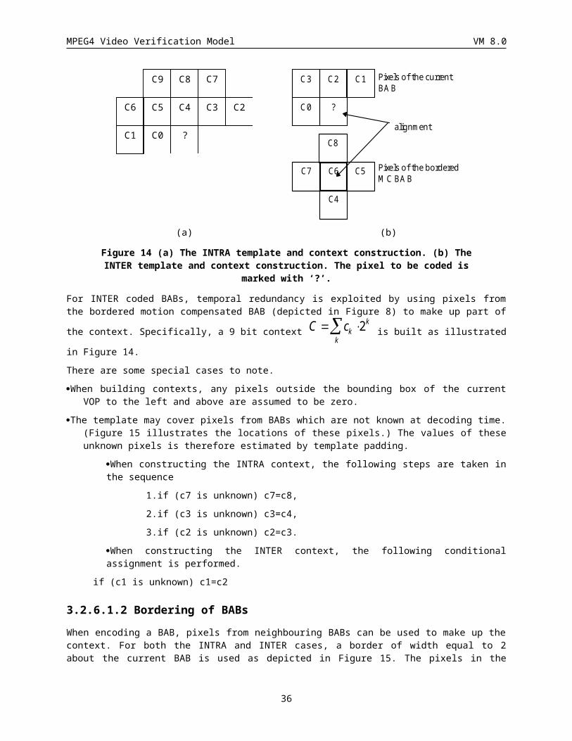
MPEG4 Video Verification Model VM 8.0
input images. It corresponds to the distance, in pixels, from the edge of the binary mask to feather, where the feathering is performed on interior shape pixels within the specified 4-connectivity distance of an edge of the mask. This integer is transmitted as part of the VOL descriptor as the 3-bit parameter video_object_layer_feather_dist. The binary alpha mask is compressed using the default algorithm. The decoder reconstructs the complete binary alpha mask and then iterates through filtering with the feathering filters video_object_layer_feather_dist times (at most, 7 times). For each iteration, a feathering filter tapers the alpha values of the boundary pixels of (either 255 or VOP_constant_alpha_value ) as depicted below.
feathering filter at eachiteration
255 orVOP_constant_alpha_value
binaryshape
arbitarygray value
Figure 17 Example of filtering.
3.2.7.2.1.5.1 Description of Feathering Filter
A feathering filter, which can be different for each iteration, is specified in Video Object Layer.
All feathering filters take 3x3 kernel for shape adaptive behavior as depicted in Figure 18, in which x indicates the pixel value to be modified and b3, b2, b1 and b0 indicate surrounding pixel values.
b3
b2 x b1
b0
Figure 18 3x3 filter kernel.
Feathering is performed according to the following rules.
Pixels of input alpha mask are labeled as 1 if the alpha value is 255(or VOP_constant_alpha_value), and 0 otherwise.
Then, if x = 0, the pixel value is left intact. If x = 1, the pixel value is replaced with the value depending on the surrounding conditions as specified in Table 4.
If the number of filtering iteration is more than 1, the filters are cascaded.
b3 b2 b2 b0 x’
0 0 0 0 x0
0 0 0 1 x1
0 0 1 0 x2
0 0 1 1 x3
0 1 0 0 x4
0 1 0 1 x5
36
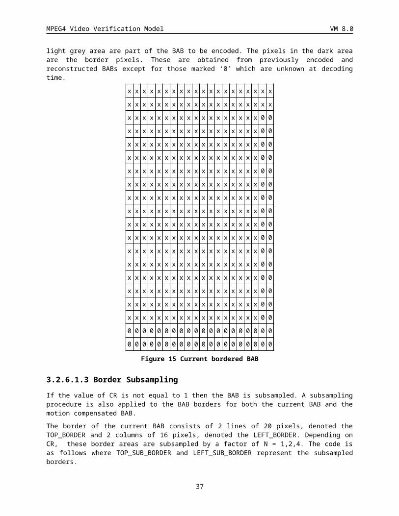
MPEG4 Video Verification Model VM 8.0
0 1 1 0 x6
0 1 1 1 x7
1 0 0 0 x8
1 0 0 1 x9
1 0 1 0 x10
1 0 1 1 x11
1 1 0 0 x12
1 1 0 1 x13
1 1 1 0 x14
Table 4 Feathering filter description table.
Note that there is no need to define the new value x’ in case of (b3, b2, b1, b0) = ‘1111’, because the pixel is not at the boundary. Thus, the feathering filter is described by the table that consists of 15 entries, for which 8 bit FLC is used (Although VLC of differential values might be used, FLC is tentatively used for simplification. It takes 120 bits though, the tapering of binary mask can form arbitrary gray-scale profile, and 1 or 2 iteration(s) are enough for reconstruction of anti-aliased gray-scale mask. For example, if we choose two iterations of filtering, 85 for the first table entries , and 175 for the second table entries, the filtering effect is exactly same to feathering of the 4-connectivity distance transform with specifying the distance as 2. The details of this feathering filter is described by the C-code function “feathering_iteration()” in Appendix.
3.2.7.2.1.5.2 Boundary Analysis
Since we have to start with given gray-scale alpha masks, the automatic analysis tool is mandatory for this “binary alpha mask + feathering effect” approach.
In section , we provide the C-code function “feathering_analysis()” to automatically define the number of iterations, and the feathering filter description (i.e., table entries) for each iteration.
To determine the number of iterations, we define a threshold to evaluate the portion of approximation. At the n-th iteration of filtering, if any tapered value is larger than
OPAQUE_LEVEL(e.g., 255) * TAPERING_LIMIT / 100,
no further iteration is applied.
In core experiments, the threshold "TAPERING_LIMIT" is set to 90(i.e., 90%).
3.2.7.2.1.6 Feathering Filter and Constant Alpha:
This mode is nearly identical to the Constant Alpha Mode with the exception that, as in the Feathering Filter Mode, the 3-bit parameter specifying the number of pixels over which to feather (video_object_layer_feather_dist), is transmitted as part of the Video Object Layer descriptor. This is followed by a 120 bit filter description for each iteration specified, similar to the Feathering Filter Mode. Each input grayscale alpha mask is analyzed and categorized as either a Constant Alpha mask or a standard grayscale mask as described for the Constant Alpha Mode. If a mask is categorized as a Constant Alpha mask, then it is transmitted as described in the Constant Alpha Mode. In the decoder, the binary mask is decoded, the alpha values are converted to VOP_constant_alpha_value, and then the mask is passed to the feathering filter algorithm. Filtering output values are scaled as
alpha_value = filter_output * VOP_constant_alpha_value / 255.
If the mask is labeled as a standard grayscale mask, then the 1-bit VOP_constant_alpha value is set to 0 and it is compressed with the default grayscale alpha mask compression algorithm, but it is not feathered.
37
MPEG4 Video Verification Model VM 8.0
3.2.7.2.1.7 No Effects Mode
The binary or grayscale alpha mask is compressed as specified by the video_object_layer_shape descriptor.
3.3 Motion Estimation and Compensation In order to perform motion prediction on a per VOP basis, the motion estimation of the blocks on the VOP borders has to be modified from block matching to polygon matching. Furthermore, a special padding technique, i.e., the macroblock-based repetitive padding, is required for the reference VOP. The details of these techniques are described in the following sections.
Since the VOPs have arbitrary shapes rather rectangular shapes, and the shapes change from time to time, some conventions is necessary to ensure the consistency of the motion compensation in the VM.
The absolute (frame) coordinate system is used for referencing all of the VOPs. At each particular time instance, a bounding rectangle that includes the shape of that VOP, as described in Section , is defined. The left and top corner, in their absolute coordinates, of the bounding box is encoded in the VOP spatial reference.
Thus, the motion vector for a particular feature inside a VOP, e.g. a macroblock, refers to the displacement of the feature in absolute coordinates. No alignment of VOP bounding boxes at different time instances is performed.
In addition to the motion estimation and compensation mode, two additional modes are supported, namely, unrestricted and advanced modes are supported. In all three modes, the motion vector search range is up to [-2f_code+3, 2f_code+3 - 0.5] where 0 <= f_code <= 7. This mode differs from the unrestricted motion mainly by restricting the motion vectors inside the bounding box of the VOP. The advanced mode allows multiple motion vectors in one macroblock and overlapped motion compensation. Note that in all three modes, macroblock-based padding of the VOP is needed for both motion estimation and compensation.
3.3.1 Padding ProcessThe padding process defines the values of luminance and chrominance samples outside the VOP for prediction of arbitrarily shaped objects. Figure 19 shows a simplified diagram of this process.
38
MPEG4 Video Verification Model VM 8.0
VerticalRepetitivePadding
ExtendedPadding
HorizontalRepetitivePadding
Saturation
Predictions
Framestores
f [y][x]
d [y][x]
s [y][x]
s’ [y][x]
hor_pad [y][x] hv_pad [y][x]
d’ [y][x]
Figure 19: Simplified padding process
A decoded macroblock d[y][x] is padded by referring to the corresponding decoded shape block s[y][x]. The luminance component is padded per 16 x 16 samples, while the chrominance components are padded per 8 x 8 samples. A macroblock that lies on the VOP boundary (hereafter referred to as a boundary macroblock) is padded by replicating the boundary samples of the VOP towards the exterior. This process is divided into horizontal repetitive padding and vertical repetitive padding. The remaining macroblocks that are completely outside the VOP (hereafter referred to as exterior macroblocks) are filled by extended padding.
NOTE - The padding process is applied to all macroblocks inside the bounding rectangle of a VOP. The bounding rectangle of the luminance component is defined by vop_width and vop_height extended to multiple of 16, while that of the chrominance components is defined by (vop_width>>1) and (vop_height>>1) extended to multiple of 8.
3.3.1.1 Horizontal repetitive paddingEach sample at the boundary of a VOP is replicated horizontally to the left and/or right direction in order to fill the transparent region outside the VOP of a boundary macroblock. If there are two boundary sample values for filling a sample outside of a VOP, the two boundary samples are averaged (//2).
hor_pad[y][x] is generated by any process equivalent to the following example. For every line with at least one shape sample s[y][x] == 1(inside the VOP) :
for (x=0; x<N; x++) {
if (s[y][x] == 1) { hor_pad[y][x] = d[y][x]; s’[y][x] = 1; }
else {
39
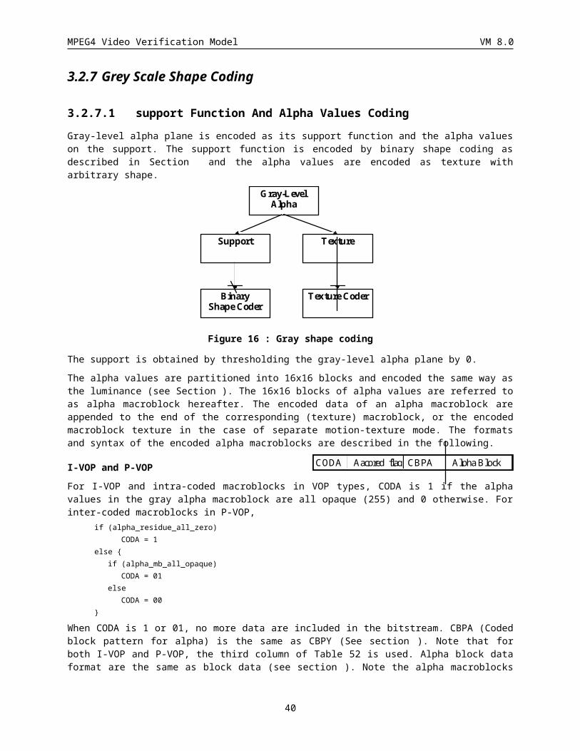
MPEG4 Video Verification Model VM 8.0
if ( s[y][x’] == 1 && s[y][x”] == 1) {
hor_pad[y][x] = (d[y][x’]+ d[y][x”])//2;
s’[y][x] = 1;
} else if ( s[y][x’] == 1 ) {
hor_pad[y][x] = d[y][x’]; s’[y][x] = 1;
} else if ( s[y][x”] == 1 ) {
hor_pad[y][x] = d[y][x”]; s’[y][x] = 1;
}
}
}
where x’ is the location of the nearest valid sample (s[y][x’] == 1) at the VOP boundary to the left of the current location x, x” is the location of the nearest boundary sample to the right, and N is the number of samples of a line. s’[y][x] is initialized to 0.
3.3.1.2 Vertical repetitive paddingThe remaining unfilled transparent horizontal samples (where s’[y][x] == 0) from are padded by a similar process as the horizontal repetitive padding but in the vertical direction. The samples already filled in are treated as if they were inside the VOP for the purpose of this vertical pass.
hv_pad[y][x] is generated by any process equivalent to the following example. For every column of hor_pad[y][x] :
for (y=0; y<M; y++) {
if (s’[y][x] == 1) hv_pad[y][x] =hor_pad[y][x];
else {
if ( s’[y’][x] == 1 && s’[y”][x] == 1 )
hv_pad[y][x] = (hor_pad[y’][x] + hor_pad[y”][x])//2;
else if ( s’[y’][x] == 1 ) hv_pad[y][x] = hor_pad[y’][x];
else if (s’[y”][x] == 1 ) hv_pad[y][x] = hor_pad[y”][x];
}
}
where y’ is the location of the nearest valid sample (s’[y’][x] == 1) above the current location y at the boundary of hv_pad, y” is the location of the nearest boundary sample below y, and M is the number of samples of a column.
40
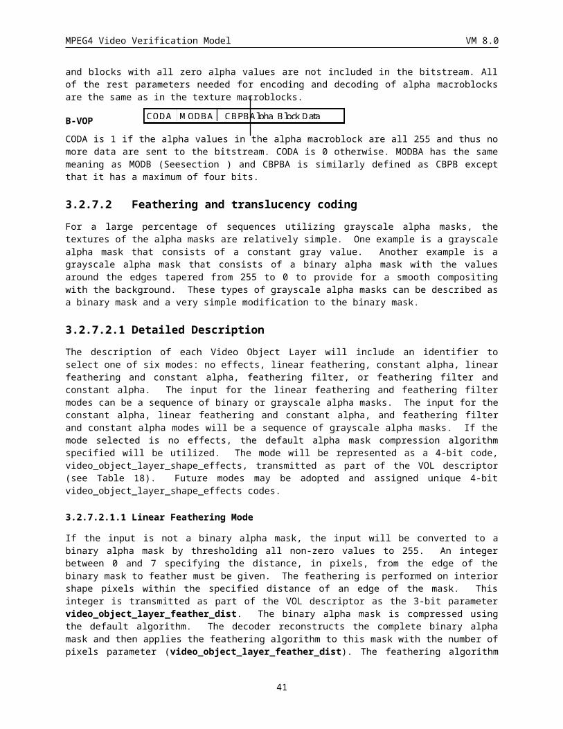
MPEG4 Video Verification Model VM 8.0
3.3.1.3 Extended paddingExterior macroblocks immediately next to boundary macroblocks are filled by replicating the samples at the border of the boundary macroblocks. Note that the boundary macroblocks have been completely padded in and . If an exterior macroblock is next to more than one boundary macroblocks, one of the macroblocks is chosen, according to the following convention, for reference.
The boundary macroblocks surrounding an exterior macroblock are numbered in priority according to Figure 20:Priority of boundary macroblocks surrounding an exterior macroblock. The exterior macroblock is then padded by replicating upwards, downwards, leftwards, or rightwards the row of samples from the horizontal or vertical border of the boundary macroblock having the largest priority number.
The remaining exterior macroblocks (not located next to any boundary macroblocks) are filled with 128.
Exteriormacroblock
Boundarymacroblock 3
Boundarymacroblock 0
Boundarymacroblock 1
Boundarymacroblock 2
Figure 20: Priority of boundary macroblocks surrounding an exterior macroblock
3.3.1.4 Padding for chrominance componentsChrominance components are padded according to clauses through for each 8 x 8 block. The padding is performed by referring to a shape block generated by decimating the shape block of the corresponding luminance component. For each 2 x 2 adjacent luminance shape samples, the corresponding chrominance shape sample is set to 1 if any of the four luminance shape samples are 1. Otherwise the chrominance shape sample is set to 0.
3.3.1.5 Padding of interlaced macroblocksMacroblocks of interlaced VOPs (interlaced == 1) are padded according to clauses through . The vertical padding of the luminance component (as in clauses and ), however, is performed for each field independently. A sample outside of a VOP is therefore filled with the value of the nearest boundary sample of the same field.
41
MPEG4 Video Verification Model VM 8.0
3.3.2 Basic Motion Techniques
3.3.2.1 Modified Block (Polygon) MatchingThe bounding rectangle of the VOP is first extended on the right-bottom side to multiples of macroblock size. So the size of the bounding rectangle of the luminance VOP is multiples of 16x16, while the size of the chrominance plane is multiples of 8x8. The alpha value of the extended pixels is set to be zero. The macroblocks are formed by dividing the extended bounding rectangles into 16x16 blocks. Zero stuffing is used for these extended pixels. SAD (Sum of Absolute Difference) is used as error measure. The original alpha plane for the VOP is used to exclude the pixels of the macroblock that are outside the VOP. SAD is computed only for the pixels with nonzero alpha value. This forms a polygon for the macro block that includes the VOP boundary. Figure 21 illustrates an example.
macroblock
transparent pixels
Pixels for polygonmatching
VOP
Figure 21: Polygon matching for an arbitrary shape VOP.
The reference VOP is padded based on its own shape information. For example, when the reference VOP is smaller than the current VOP, the reference is not padded up to the size of the current VOP.
In case the 8x8 advanced prediction mode is chosen and all of the pixels in an 8x8 block are transparent (completely outside the VOP), no matching needs to be done.
3.3.2.2 Integer pixel motion estimationBoth 8x8 and 16x16 vectors are obtained from the search algorithm. Only a small amount of additional computation is needed to obtain the 8x8 integer vectors in addition to the 16x16 vectors.
The search is made with integer pixel displacement and for the Y component. The comparisons are made between the incoming block and the displaced block in the previous reconstructed VOP. Note that the previous reconstructed VOP has to be padded in a macroblock basis as described in section . A full search around the original macroblock position is used with a maximum search area depending on the range provided by the f_code.
SAD N (x, y) original previousi1, j1
N, N
*(!(Alpha original 0)),
x, y"up to [-64, 63]", N =16 or 8For the zero vector SAD16(0,0) is reduced to favor the zero vector when there is no significant difference.
SAD SAD NB16 160 0 0 0 2 1( , ) ( , ) ( / )
where N B = the number of pixels inside the VOP multiplied by 2(bits_per_pixel-8).
The (x,y) pair resulting in the lowest SAD16 is chosen as the 16x16 integer pixel motion vector, V0. The corresponding SAD is SAD16(x,y).
42
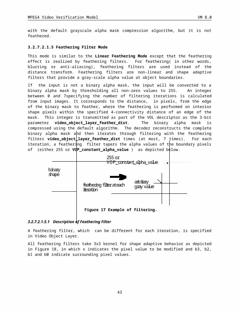
MPEG4 Video Verification Model VM 8.0
Likewise, the (x,y) pairs resulting in the lowest SAD8(x,y) are chosen to give the 4 8x8 vectors V1, V2, V3 and V4.
The 8x8 based SAD for the macroblock is
SAD SAD x yKx
K
8 81
( , )
where 0<K<=4 is the number of 8x8 blocks that do not lie outside of the VOP shape. The following rule , and
SAD SAD x y SADKxinter min( ( , ), )16 8
Instead of full search, the 8x8 search is centered around 16x16 vector, with a search window of 2 pixels, for the following reasons :
1. it is faster,
2. it generally gives better results because of a better OBMC filtering effect and less bits spent for vectors,
3. if the Extended MV Range is used, the search range around the motion vector predictor will be less limited.
If interlaced video is being encoded, four field motion vectors are calculated for every macroblock (in addition to existing 16x16 and 8x8 motion vectors described above) for each reference VOP. The field motion vectors correspond to the four combinations of current field (top or bottom) and reference field (top or bottom). The top field consists of even lines (0, 2, 4, …H-2), and the bottom field is composed of the odd lines (1, 3, 5, … H-1, where H is the frame height). The full-pel field motion vector (fxp,q, fyp,q) is defined by the minimum sum of absolute differences, fSADp,q, given by
where
(x0,y0) Upper left corner coordinates of the current macroblockp Field in the current frame/VOP (0 for top; 1 for bottom)q Field in reference frame/VOP (0 for top; 1 for bottom)C[x,y] Current macroblock luminance samplesA[x,y] Current macroblock alpha valuesOR[x,y] Reconstructed reference VOP luminance samplesS Search region: ( , ): ,_ _x y x yf code f code 2 23 3
(fxp,q, fyp,q) which results in the minimum sum above
The field motion vectors are unrestricted in the sense that pixels referenced above might fall outside of the VOP bounding box but within the padded extension. If any pixel are required beyond the padded reference VOPs, then the candidate motion vector is eliminated from the search region, S. For the core experiments, the padding width is equal to the motion estimation radius.
The full-pel SAD for an interlaced P-VOP macroblock is
SAD SAD x y SAD fSAD fSAD fSAD fSADKxinter min( ( , ), , min( , ) min( , )), , , ,16 8 0 0 0 1 1 0 1 1
3.3.2.3 INTRA/INTER mode decision After the integer pixel motion estimation the coder makes a decision on whether to use INTRA or INTER prediction in the coding. The following parameters are calculated to make the INTRA/INTER decision:
43
fSAD C i j p OR x x i y y j q A i j pp qx y Sy even ij
,( , )
[ , ] [ , ] * ( [ , ] ! )
min 2 2 2 00 0
0
15
0
7
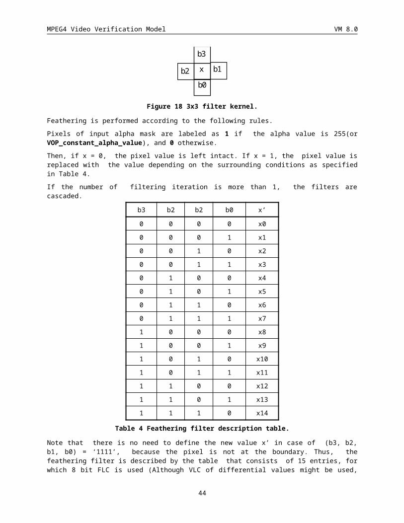
MPEG4 Video Verification Model VM 8.0
Nc
jicNoriginalmeanMB
1,1
/)(_
A original MB mean Alphai j
original _ * (!( ))
,
,
1 1
16 16
0
Nc is the number of pixels inside the VOP.
INTRA mode is chosen if: A SAD NB ( * )inter 2
Notice that if SAD16(0,0) is used, this is the value that is already reduced as explained above.
If INTRA mode is chosen, no further operations are necessary for the motion search. If INTER mode is chosen the motion search continues with half sample search around the V0 position.
3.3.2.4 Half sample searchHalf sample search is performed for 16x16 vectors as well as for 8x8 vectors. The half sample search is done using the previous reconstructed VOP. The search is performed on the luminance component of the macroblock, and the search area is ±1 half sample around the target matrix pointed to by V0, V1, V2, V3 or V4. For the 16x16 search the zero vector sad, SAD(0,0), is reduced by NB/2+1 as for the integer search.
The half sample values are found using the interpolation described in a = A, b = (A + B + 1 -rounding_control) / 2 c = (A + C + 1 - rounding_control) / 2, d = (A + B + C + D + 2 - rounding_control) / 4 “/” denotes division by truncation. and which corresponds to bilinear interpolation. The value of rounding_control is defined using the VOP_rounding_type bit in the VOP header (see section ). Note that the samples outside the padded region cannot be used for interpolation.
+ +
+ +
+ Integer pixel position
Half pixel position
A B
C D
a b
c d
a = A, b = (A + B + 1 - rounding_control) / 2c = (A + C + 1 - rounding_control) / 2, d = (A + B + C + D + 2 - rounding_control) / 4“/” denotes division by truncation.
Figure 22: Interpolation scheme for half sample search.
The vector resulting in the best match during the half sample search is named MV. MV consists of horizontal and vertical components (MVx, MVy), both measured in half sample units.
For interlaced video, the half-sample search used to refine the field motion vectors is conducted by vertically interpolating between lines of the same field. The field motion vectors are calculated in frame coordinates; that is the vertical coordinates of A and C in a = A, b = (A + B + 1 - rounding_control) / 2 c = (A + C + 1 -rounding_control) / 2, d = (A + B + C + D + 2 - rounding_control) / 4 “/” denotes division by truncation. differ by 2 and the vertical component of the field motion vectors are even. If the minimum SAD is obtained by vertical (i.e. point c above) or vertical and horizontal (i.e. point d above) interpolation, then the vectical component of the half sample motion vector becomes an odd integer.
3.3.2.5 Decision on 16x16 or 8x8 prediction modeSAD for the best half sample 16x16 vector (including subtraction of NB/2+1 if the vector is (0,0)):
44
MPEG4 Video Verification Model VM 8.0
SAD x y16 ( , )
SAD for the whole macro block for the best half sample 8x8 vectors:
SAD SAD x yKx
K
8 81
( , )
where 0<K<=4 is the number of 8x8 blocks that do not lie outside of the VOP shape. The following rule applies:
If
SAD SAD Nk B* ( / )8 16 2 1 ,
choose 8x8 prediction
otherwise choose 16x16 prediction
3.3.2.6 Interlaced video prediction mode decisionFor P-VOPs, each predicted (non-intra) macroblock can use 16x16, 8x8 or field motion compensation. The first step is to select the best reference field for predicting the top and bottom field of the current macroblock. This selection is made by choosing the reference field which has the smallest SAD (SAD top and SADbottom) from the field half sample search. The overall prediction mode decision is based on choosing the minimum of
SAD16, SADK*8 + NB/2 + 1, SADtop + SADbottom + NB/4 + 1
If the first term above is the minimum, 16x16 prediction is used. If the second term is the smallest, 8x8 motion compenstaiton is used. If the last expression is the minimum, field based motion estimation is selected.
3.3.2.7 Differential coding of motion vectorsWhen using INTER mode coding, the motion vector must be transmitted. The motion vector components (horizontal and vertical) are coded differentially by using a spatial neighborhood of three motion vectors already transmitted (Figure 23). These three motion vectors are candidate predictors for the differential coding. The differential coding of motion vectors is performed with reference to the reconstructed shape.
In the special cases at the borders of the current VOP the following decision rules are applied:
1.If the macroblock of one and only one candidate predictor is outside of the VOP, it is set to zero.
2.If the macroblocks of two and only two candidate predictors are outside of the VOP, they are set to the third candidate predictor.
3.If the macroblocks of all three candidate predictors are outside of the VOP, they are set to zero.
The motion vector coding is performed separately on the horizontal and vertical components. For each component, the median value of the three candidates for the same component is computed:
Px Median MV x MV x MV xPy Median MV y MV y MV y
( , , )( , , )
1 2 31 2 3
For instance, if MV1=(-2,3), MV2=(1,5) and MV3=(-1,7), then Px = -1 and Py = 5.
If the error_resilient_disable_flag is not set, one dimensional prediction is used:
Px = MV1x
Py = MV1y
MV1 takes the value 0 after a resynchronisation marker.
The Variable Length Codes for the vector differences MVDx and MVDy are listed in Table 54.
45
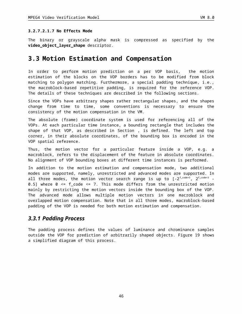
MPEG4 Video Verification Model VM 8.0
MVDx MVx PxMVDy MVy Py
For prediction of 8x8 vectors see Section .
MV2 MV3
MV1 MV
MV3MV2 MV2
MV1
MV1 MV
MVMV(0,0)
(0,0)
MV : Current motion vectorMV1: Previous motion vectorMV2: Above motion vectorMV3: Above right motion vector
: VOP border
MV1 MV1
Figure 23: Motion vector prediction.
When interlaced video is encoded, if one or more of MV1, MV2 or MV3 refers to a field motion compensated macroblock, the value of MVi is the average of the two field motion vectors. If a 1/4 or 3/4 pixel offset is obtained by the average, it is replaced with a 1/2 pixel offset.
If the current macroblock is a field motion compensated macroblock, then the same prediction motion vector (Px, Py) is used for both field motion vectors. Because the vertical component of a field motion vector is integral, the vertical differential motion vector encoded in the bitstream is
MVDyfield = (Mvy - (int)Py) / 2
where (int)Py means truncate Py toward zero to the nearest integral value.
3.3.3 Unrestricted Motion Estimation/Compensation
3.3.3.1 Motion estimation over VOP boundariesAn unrestricted motion estimation mode is used for VOP motion estimation. The technique is to improve the motion estimation techniques, especially for VOP-based coding schemes. In this technique, the error signal is generated by extending the reference VOP to enough size, padding the extended VOP, applying motion estimation, and taking the difference of the original and the estimated signals. Note that padding is performed only on the reference VOP. Target VOP remains the same except for extending it to multiples of 16x16 blocks.
For the case of a rectangular VOP (non-arbitrary shape), the rectangle is extended in all four directions (left, top, right, and bottom) by 2f_code+3 pixels by repetitive padding. For arbitrary shape VOPs, the bounding box padded as described in section , is further extended in all four directions (left, top, right, and bottom) by 2 f_code+3 pixels by repetitive padding.
Apply modified block (polygon) matching described in Section to compute the motion vectors.
46
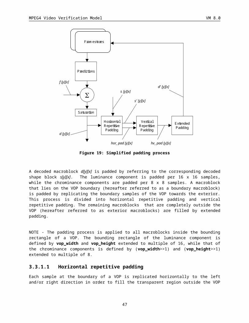
MPEG4 Video Verification Model VM 8.0
3.3.3.2 Motion compensation over VOP boundariesFor unrestricted motion compensation, the motion vectors are allowed to point outside the decoded area of a reference VOP. For an arbitrary shape VOP, the decoded area refers to the area within the bounding box, padded as described in section . A bounding box is defined by vop_width and vop_height extended to multiple of 16. When a sample referenced by a motion vector stays outside the decoded VOP area, an edge sample is used. This edge sample is retrieved by limiting the motion vector to the last full pel position inside the decoded VOP area. Limitation of a motion vector is performed on a sample basis and separately for each component of the motion vector.
The co-ordinates of a reference sample in the reference VOP, (yref, xref) is determined as follows :
xref = MIN ( MAX (x+dx, 0), xdim-1 ) )
yref = MIN ( MAX (y+dy, 0), ydim-1) )
where (y, x) is the co-ordinates of a sample in the current VOP, (yref, xref) is the co-ordinates of a sample in the reference VOP, (dy, dx) is the motion vector, and (ydim, xdim) is the dimension of the reference VOP. Note that for rectangular VOP, a reference VOP is defined by video_object_layer_width and video_object_layer_height. For an arbitrary shape VOP, a reference VOP of luminance is defined by vop_width and vop_height extended to multiple of 16, while that of chrominance is defined by (vop_width>>1) and (vop_height>>1) extended to multiple of 8.
3.3.4 Advanced prediction mode
3.3.4.1 Formation of the motion vectorsOne/two/four vectors decision is indicated by the MCBPC codeword and field_prediction flag for each macroblock. If one motion vector is transmitted for a certain macroblock, this is defined as four vectors with the same value as the MV. When two field motion vectors are transmitted each of the four block prediction motion vectors has the value equal to the average of the field motion vectors (rounded such that all fractional pixel offsets become the half pixel offset). If MCBPC indicates that four motion vectors are transmitted for the current macroblock, the information for the first motion vector is transmitted as the codeword MVD and the information for the three additional motion vectors is transmitted as the codewords MVD2-4.
The vectors are obtained by adding predictors to the vector differences indicated by MVD and MVD 2-4 in a similar way as when only one motion vector per macroblock is present, according to the decision rules given in Section . Again the predictors are calculated separately for the horizontal and vertical components. However, the candidate predictors MV1, MV2 and MV3 are redefined as indicated in Figure 24. If only one vector per macroblock is present, MV1, MV2 and MV3 are defined as for the 8*8 block numbered 1 in Figure 71.
47
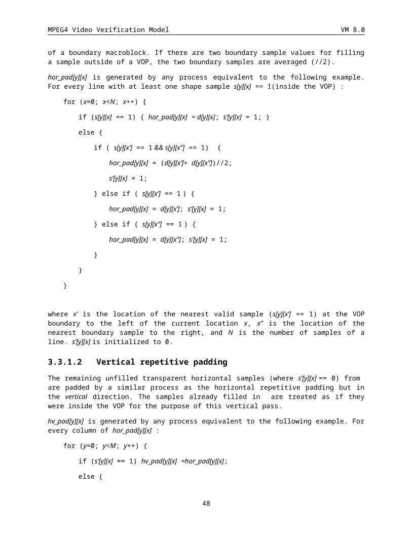
MPEG4 Video Verification Model VM 8.0
Figure 24: Redefinition of the candidate predictors MV1, MV2 and MV3 for each of the luminance blocks in a macroblock
If four vectors are used, each of the motion vectors is used for all pixels in one of the four luminance blocks in the macroblock. The numbering of the motion vectors is equivalent to the numbering of the four luminance blocks as given in Figure 71. Motion vector MVDCHR for both chrominance blocks is derived by calculating the sum of the K luminance vectors, that corresponds to K 8x8 blocks that do not lie outside the VOP shape and dividing this sum by 2*); the component values of the resulting sixteenth/twelfth/eighth/fourth sample resolution vectors are modified towards the nearest half sample position as indicated in Table 5 to Table 8.
sixteenth pixel position 0 1 2 3 4 5 6 7 8 9 10 11 12 13 14 15 //16
resulting position 0 0 0 1 1 1 1 1 1 1 1 1 1 1 2 2 //2
Table 5 Modification of sixteenth sample resolution chrominance vector components
twelfth pixel position 0 1 2 3 4 5 6 7 8 9 10 11 //12
resulting position 0 0 1 1 1 1 1 1 1 1 2 2 //2
Table 6 Modification of twelfth sample resolution chrominance vector components
eighth pixel position 0 1 2 3 4 5 6 7 //8
resulting position 0 0 1 1 1 1 1 2 //2
Table 7 Modification of eighth sample resolution chrominance vector components
fourth pixel position 0 1 2 3 //4
resulting position 0 1 1 1 //2
Table 8 Modification of fourth sample resolution chrominance vector components
Half sample values are found using bilinear interpolation as described in Section . The prediction for luminance is obtained by overlapped motion compensation as described above. The prediction for chrominance is obtained by
48
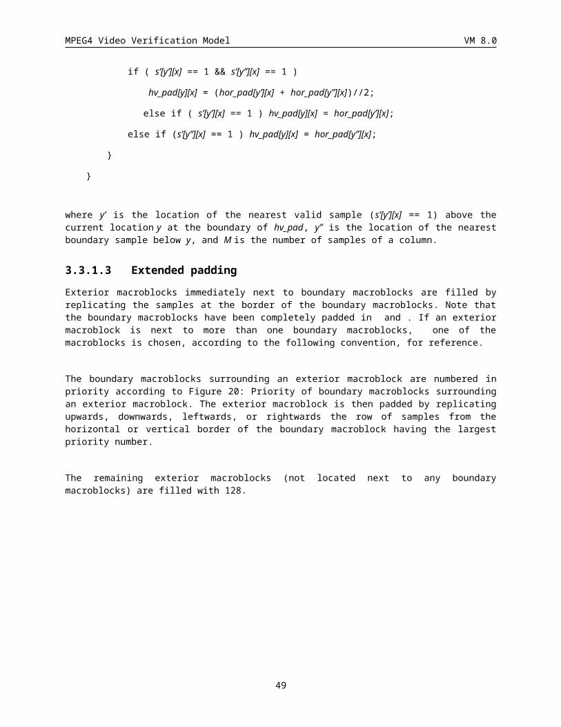
MPEG4 Video Verification Model VM 8.0
applying the motion vector MVDCHR to all pixels in the two chrominance blocks (as it is done in the default prediction mode).
The predictor for MVD and MVD2-4 is defined as the median value of the vector components MV1, MV2 and MV3 as defined in Section .
3.3.4.2 Overlapped motion compensation for luminanceEach pixel in an 8*8 luminance prediction block is a weighted sum of three prediction values, divided by 8 (with rounding). In order to obtain the three prediction values, three motion vectors are used: the motion vector of the current luminance block, and two out of four "remote" vectors:
· the motion vector of the block at the left or right side of the current luminance block;
· the motion vector of the block above or below the current luminance block.
For each pixel, the remote motion vectors of the blocks at the two nearest block borders are used. This means that for the upper half of the block the motion vector corresponding to the block above the current block is used, while for the lower half of the block the motion vector corresponding to the block below the current block is used (see Figure 26). Similarly, for the left half of the block the motion vector corresponding to the block at the left side of the current block is used, while for the right half of the block the motion vector corresponding to the block at the right side of the current block is used (see Figure 27).
The creation of each pixel, p i j( , ), in an 8*8 luminance prediction block is governed by the following equation:
p i j q i j H i j r i j H i j s i j H i j( , ) ( ( , ) ( , ) ( , ) ( , ) ( , ) ( , ) ) / /8, 0 1 2 4
where q i j r i j( , ), ( , ), and s i j( , ) are the pixels from the referenced picture as defined by
q i j p i MV j MV
r i j p i MV j MV
s i j p i MV j MV
x y
x y
x y
( , ) ( , ),
( , ) ( , ),
( , ) ( , ).
0 0
1 1
2 2
Here, ( , )MV MVx y0 0 denotes the motion vector for the current block, ( , )MV MVx y
1 1 denotes the motion vector
of the block either above or below, and ( , )MV MVx y2 2 denotes the motion vector either to the left or right of the
current block as defined above.
The matrices H i j H i j0 1( , ), ( , ) and H i j2 ( , ) are defined in Figure 25, Figure 26, and Figure 27, where ( , )i j denotes the column and row, respectively, of the matrix.
If one of the surrounding blocks was not coded, the corresponding remote motion vector is set to zero. If one of the surrounding blocks was coded in INTRA mode, the corresponding remote motion vector is replaced by the motion vector for the current block. If the current block is at the border of the VOP and therefore a surrounding block is not present, the corresponding remote motion vector is replaced by the current motion vector. In addition, if the current block is at the bottom of the macroblock, the remote motion vector corresponding with an 8*8 luminance block in the macroblock below the current macroblock is replaced by the motion vector for the current block.
The weighting values for the prediction are given in Figure 25, Figure 26, and Figure 27.
4 5 5 5 5 5 5 4
5 5 5 5 5 5 5 5
5 5 6 6 6 6 5 5
5 5 6 6 6 6 5 5
5 5 6 6 6 6 5 5
49
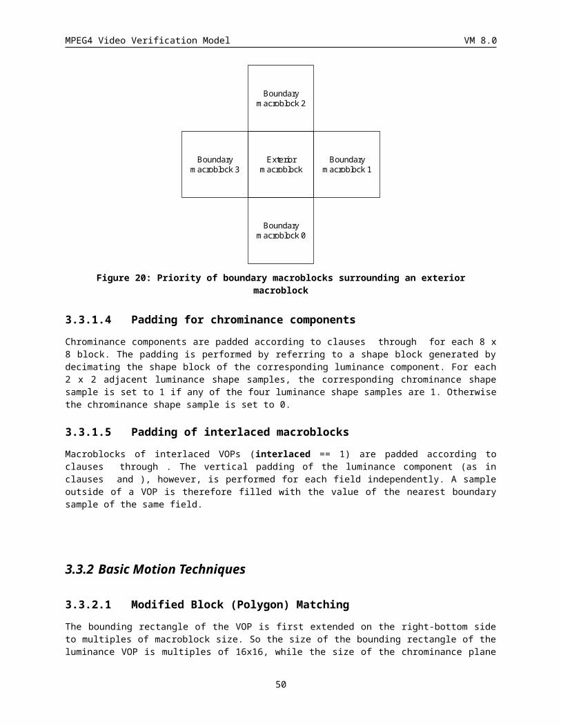
MPEG4 Video Verification Model VM 8.0
5 5 6 6 6 6 5 5
5 5 5 5 5 5 5 5
4 5 5 5 5 5 5 4
Figure 25: Weighting values, H0 , for prediction with motion vector of current luminance block
2 2 2 2 2 2 2 2
1 1 2 2 2 2 1 1
1 1 1 1 1 1 1 1
1 1 1 1 1 1 1 1
1 1 1 1 1 1 1 1
1 1 1 1 1 1 1 1
1 1 2 2 2 2 1 1
2 2 2 2 2 2 2 2
Figure 26: Weighting values, H1 , for prediction with motion vectors of the luminance blocks on top or bottom of current luminance block
2 1 1 1 1 1 1 2
2 2 1 1 1 1 2 2
2 2 1 1 1 1 2 2
2 2 1 1 1 1 2 2
2 2 1 1 1 1 2 2
2 2 1 1 1 1 2 2
2 2 1 1 1 1 2 2
2 1 1 1 1 1 1 2
Figure 27: Weighting values, H2 , for prediction with motion vectors of the luminance blocks to the left or right of current luminance block
3.3.5 Interlaced Motion CompensationWhen field-based motion compensation is specified (by the field_prediction bit being ‘1’), two field motion vectors and corresponding reference fields are used to generate the prediction from each reference VOP.
The luminance prediction is generated as follows: The even lines of the macroblock (0, 2, 4 ... 14) are defined by the top field motion vector using the reference field specified. The motion vector is specified in frame coordinates -- full pixel vertical displacements correspond to even integral values of vertical motion vector coordinate and a half pixel vertical displacement is denoted by odd integral values. When a half pixel vertical offset is specified, only pixels from lines within the same reference field are combined according to the methods specifed in section .
The same procedure is used to define the odd luminance lines of the macroblock using the bottom field motion vector and reference field.
50
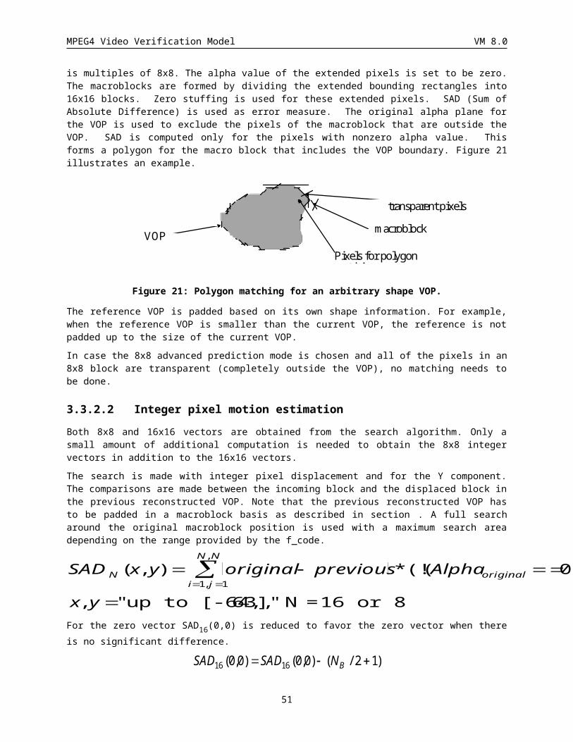
MPEG4 Video Verification Model VM 8.0
Chrominance 4:2:0 motion compensation is done field-wise. The even lines of a chrominance frame/VOP derived from the top field chrominance and the odd lines contain the bottom field chrominance. The even chrominance lines (0, 2, 4, 6) are defined by the top field motion vector and reference field and the odd chrominance lines (1, 3, 5, 7) are defined by the bottom field motion vector and reference field. A chrominance motion vector is derived from the (luminance) motion vector by dividing each component by 2 then rounding as follows:
· The horizontal component is rounded by mapping all fractional values into a half-pixel offset. This is the same procedure as described in Table 8 used for the advance prediction mode.
· The vertical motion vector component is an integer and the resulting chrominance motion vector vertical component is rounded to an integer. If the result of dividing by two gives a non-integral values, it is rounded to the adjacent odd integer. Note that the odd integral value denote vertical interpolation between lines of the same field.
3.4 Texture CodingThe intra VOPs and the residual data after motion compensation is coded using the same 8x8 block DCT scheme. DCT is done separately for each of the luminance and chrominance planes. When shape of the VOP is arbitrary, the macroblocks that belong to the arbitrary shape of the VOP are treated as described below. There are two types of macroblocks that belong to an arbitrarily shaped VOP: 1) those that lie completely inside the VOP shape and 2) those that lie on the boundary of the shape. The macroblocks that lie completely inside the VOP are coded using a technique identical to the technique used in H263. The intra 8x8 blocks that belong to the macroblocks lying on the border of the VOP shape are first padded as described in Section . For padding of chroma blocks, a 16x16 alpha block is decimated by the method described in Sec. . For residue blocks, the region outside the VOP within the blocks are padded with zero. Padding is performed separately for each of the luminance and chrominance 8*8 blocks by using the original alpha values of the luminance or chrominance in this 8*8 block. Transparent blocks are skipped and therefore not coded. These blocks are then coded in a manner identical to the interior blocks. Blocks that lie outside the original shape are padded using the value (128, 128, 128) for luminance and chrominance in case of Intra coding and (0, 128, 128) in case of predictive coding. The blocks that belong neither to the original nor the coded arbitrary shape but to theinside of the bounding box of a VOP are not coded at all.
3.4.1 Low Pass Extrapolation (LPE) Padding Technique
Before performing the DCT, the following block padding technique, referred to as low-pass extrapolation (LPE) padding, is applied to each intra block that has at least one transparent and one non-transparent pixel in its associated alpha information. The padding is performed in three steps.
1. Calculate the arithmetic mean value m of all block pixels f(i,j) situated within the object region R
m N f i ji j R
( / ) ( , )
( , )1
where N is the number of pixels situated within the object region R. Division by N is done by rounding to the nearest integer.
2. Assign m to each block pixel situated outside of the object region R, i.e. f(i,j) = m for all (i,j) Ï R.
3. Apply the following filtering operation to each block pixel f(i,j) outside of the object region R, starting from the top left corner of the block and proceeding row by row to the bottom right pixel
f(i,j) = [ f(i,j-1) + f(i-1,j) + f(i,j+1) + f(i+1,j)] / 4.
51
MPEG4 Video Verification Model VM 8.0
Division is done by rounding to the nearest integer. If one or more of the four pixels used for filtering are outside of the block, the corresponding pixels are not included into the filtering operation and the divisor 4 is reduced accordingly. Consider e.g. i = 0 and j = 0, in which case the above operation becomes
f(i,j) = [ f(i,j+1) + f(i+1,j)] / 2.
After this padding operation the resulting block is ready for DCT coding.
3.4.2 Adaptive Frame/Field DCTWhen interlaced video is coded, superior energy compaction can sometimes be obtained by reordering the lines of the macroblock to form 8x8 luminance blocks consisting of data from one field. Field DCT line order is used when
( ) ( ) ( ) ( ), , , , , , ,p p p p p p p pi jji
i j i j i j i jji
i j i j i j20
15
0
6
2 12
2 1 2 22
20
15
0
6
2 22
2 1 2 3,2
where pi,j is the spatial luminance data .(samples or differences) just before the 8x8 DCT is performed. The field DCT permuation is indicated by the dct_type bit having a value of 1.
When field DCT mode is used, the luminance lines (or luminance error) in the spatial domain of the macroblock are permuted from the frame DCT orientation to field DCT configuration as show below. The black regions of the diagram denote the bottom field. The resulting macroblocks are transformed, quantized and VLC encoded normally. On decoding a field DCT macroblock, the inverse permutation is performed after all luminance blocks have been obtained from the IDCT. In the 4:2:0 format, chrominance data are not effected by this mode.
Frame DCT Field DCT
3.4.3 DCTA separable 2-dimensional Discrete Cosine Transform (DCT) is used.
The IDCT function f [y][x] used in the decoding process may be any of several approximations of the saturated mathematical integer-number IDCT defined in this clause.
The NxN two dimensional DCT is defined as:
F(u, v) 2N
C(u)C(v)x0
N 1
f (x,y)cos(2x 1)u
2Ny0
N 1
cos(2y 1)v
2N
52
MPEG4 Video Verification Model VM 8.0
with u, v, x, y = 0, 1, 2, ... N-1
where x, y are spatial coordinates in the sample domain
u, v are coordinates in the transform domain
C(u), C(v) 12
for u,v0
1 otherwise
For the purpose of core experiments, all VM implementations are requested to round the results of the forward DCT calculation prior to the quantization stage of coding. That is, input to the quantization stage should be:
F’(u,v) = round (F(u,v))
where round() is the rounding to the nearest integer, with half-integer values rounded away from zero. No clamping or saturation is performed.
The definition of the DCT (also called forward DCT) is purely informative. Forward DCT is not used by the decoding process described by this specification.
The mathematical real-number inverse DCT (IDCT) is defined as:
f (x, y)2N u0
N 1
C(u)C(v)F(u,v)cos(2x 1)u
2Nv0
N 1
cos(2y 1)v
2Nf (x, y) is a real number.
The mathematical integer-number IDCT is defined as:
f ’ (x, y) = round(f (x, y))
The saturated mathematical integer-number IDCT is defined as:
f ’’ (x, y) = saturate(f ’ (x, y))
where saturate() is defined as:
saturate (x ) 2n x 2n
2n - 1 x 2n - 1x 2nx 2n - 1
n
where n is the number of bits per pixel.
Editor’s note: Suitable requirements for DCT accuracy should be defined in a manner that does not assume 8-bit data in the spatial domain.
The IDCT function f [y][x] used in the decoding process may be any of several approximations of the saturated mathematical integer-number IDCT f ’’ (x, y), provided that it meets all of the following requirements:
1) The IDCT function f [y][x] used in the decoding process shall have values always in the range [-256, 255].
2) The IDCT function f [y][x] used in the decoding process shall conform to the IEEE Standard Specification for the implementation of 8 by 8 Inverse Discrete Cosine Transform, Std 1180-1990, December 6, 1990.
3) This clause applies only when input blocks of DCT coefficients cause all the 64 values output of the mathematical integer-number IDCT f ’ (x, y) to be in the range [-384, 383].When f ’ (x, y) > 256, f [y][x] shall be equal to 255 and when f ’ (x, y) < -257, f [y][x] shall be equal to -256. For all values of f ’(x,y) in the range [-257, 256] the absolute difference between f[y][x] and f ’’(x,y) shall not be larger than 2.
4) Let F be the set of 4096 blocks Bi[y][x] (i=0..4095) defined as follows :
· Bi[0][0] = i - 2048
53
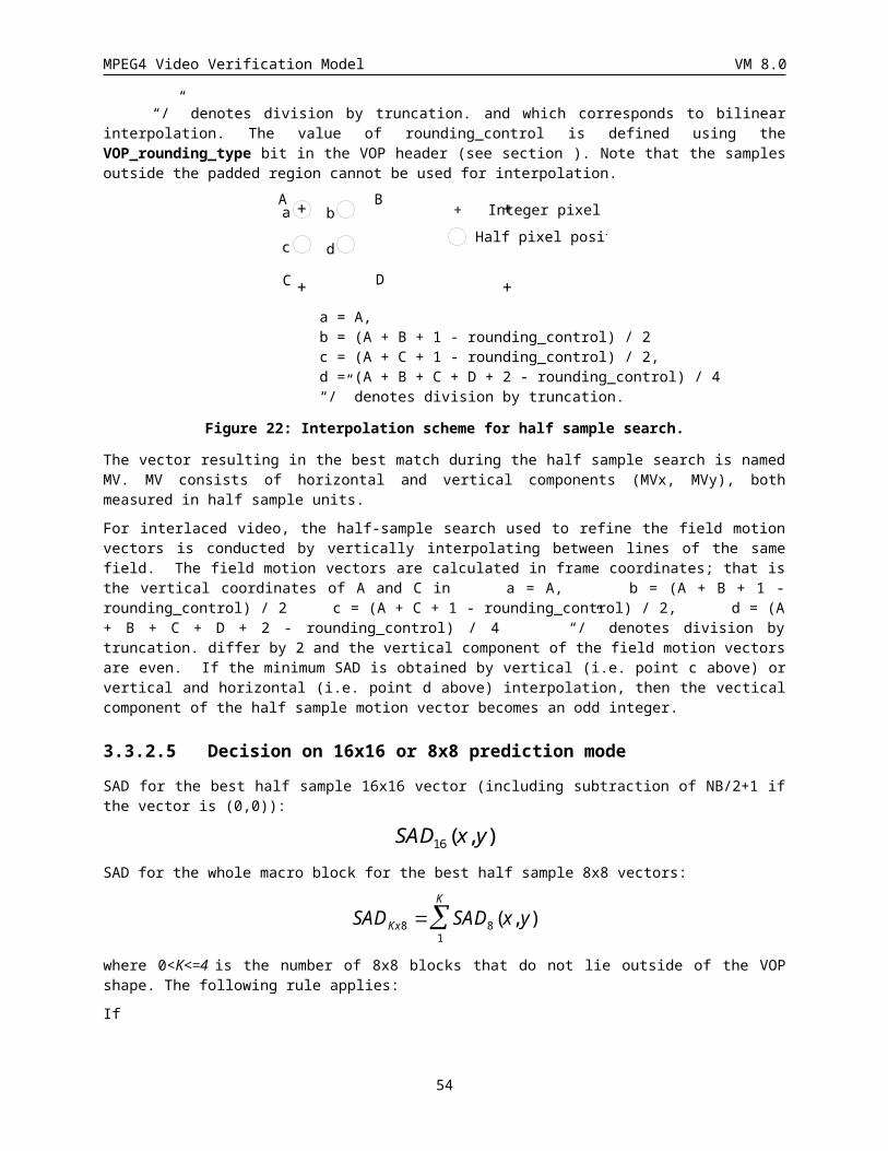
MPEG4 Video Verification Model VM 8.0
· All other coefficients Bi[y][x] other than Bi[0][0] are equal to 0
For each block Bi[y][x] that belongs to set F defined above, an IDCT that conforms to this specification shall output a block f[y][x] that has a peak error of 0 compared to the reference saturated mathematical integer-number IDCT f’’(x,y). In other words, | f[y][x] - f’’(x,y)| shall be zero for all x and y.
In addition to these requirements, the following is a recommendation on the accuracy of the IDCT function f [y][x].
1) When clause 3) does not apply, i.e. for input blocks of DCT coefficients causing the output of the mathematical integer-number IDCT f ’ (x, y) to contain one or more values out of the range [-384, 383], it is desirable that f [y][x] be as close as possible to f ’’ (x, y) for all bitstreams produced by reasonably well designed encoders.
3.4.4 SA-DCTThe SA-DCT algorithm is applied to the 8x8 blocks which straddle the boundaries of a VOP (which are boundary blocks of arbitrary shape). The SA-DCT readily replaces the VM "Macroblock-Padding" technique so that only the active pels within the VOP segment are transformed and coded. This will result in a number of DCT-coefficients which is identical to the number of pels contained in the boundary block of the VOP segment). The only remaining trivial differences to the method without SA-DCT are related to the definition of the adaptive scanning of the DCT-coefficients. All SA-DCT-coefficients are quantized and coded identical to the standard 8x8 block DCT-coefficients employing same quantizers and all DCT VLC-Tables as described in this Verification Model. No additional syntax elements or VLC-Tables are required.
3.4.4.1 Description of the SA-DCT AlgorithmFigure 28 illustrates the concept of the SA-DCT algorithm for coding an arbitrarily shaped image segment which is contained within a 8x8 pel region.
54
MPEG4 Video Verification Model VM 8.0
Figure 28 Successive steps involved for performing a SA-DCT forward transform on a block (segment) of arbitrary shape. If the segment to be coded is a rectangular region containing 8x8
pels the SA-DCT reduces to the well know standard 8x8 DCT.
The SA-DCT algorithm implemented is based on predefined orthogonal sets of DCT basis functions. In contrast to other techniques discussed in the literature the algorithm is fast to compute and does not require more computations than a normal DCT. The basic concept of the proposed method is outlined in Figure 1SA for coding an arbitrarily shaped image foreground segment contained within an 8x8 reference block. Figure 1SA-A shows an example of an image block segmented into two regions, foreground (dark) and background (light). To perform vertical SA-DCT transformation of the foreground, the length (vector size N, 0<N<9) of each column j (0<j<9) of the foreground segment is calculated, and the columns are shifted and aligned to the upper border of the 8x8 reference block (Figure 28 B). Dependent on the vector size N of each particular column of the segment, a DCT transform matrix DCT-N
DCT - N (1)p k c p kN
k p N, cos ,
012 0 1
containing a set of N DCT-N basis vectors is selected. Here c0 12
if p = 0, and c0 1 otherwise, and p
denotes the p-th DCT basis vector. The N vertical DCT-coefficients cj for each segment column data xj are calculated according to the formula
In intra coded macroblocks
In non-intra coded macroblocksc j
DCT N xN j 4
DCT N xN j 2{
In intra coded macroblocks the SA-DCT is a non-orthonormal transform except for the 8x8 block transform case. For example in Figure 28-B the right most column is transformed using DCT-3 basis vectors. After SA-DCT in vertical direction the lowest DCT-coefficients (DC values ·) for the segment columns are found along the upper border of the 8x8 reference block (Figure 1SA-C). To perform the horizontal DCT transformation (Figure 28 E), the length of each row is calculated, and the rows are shifted to the left border of the 8x8 reference block, and a horizontal DCT adapted to the size of each row is then calculated using the formulas (1) and (2). Note that horizontal SA-DCT-transformation is performed along vertical SA-DCT-coefficients with the same index (i.e. all vertical DC coefficients (·) are grouped together and are SA-DCT-transformed in horizontal dimension). Figure 28 F shows the final location of the resulting DCT coefficients within the 8x8 image block.
In this algorithm, the final number of DCT-coefficients is identical to the number of pels contained in the image segment. Also, the coefficients are located in comparable positions as in a standard 8x8 block. The DC coefficient (·) is located in the upper left border of the reference block and, dependent on the actual shape of the segment, the remaining coefficients are concentrated around the DC coefficient. Since the contour of the segment is transmitted to the receiver prior to transmitting the MB information the decoder can perform the shape-adapted inverse DCT as the reverse operation
In intra coded macroblocks
In non-intra coded macroblocksx j
DCT N c2 j 1
DCT N cN j 2{ T
T
in both horizontal and vertical segment direction. Here cj denotes a horizontal or vertical coefficient vector of size N.
55
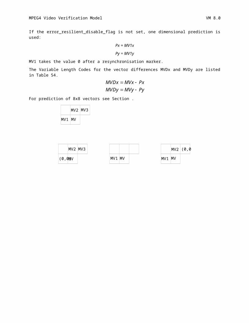
MPEG4 Video Verification Model VM 8.0
3.4.4.2 Adaptive Scanning of the SA-DCT-CoefficientsFor the coding of the SA-DCT coefficient we introduce the notation of the "active SA-DCT domain area". This domain is the dark shaded area covering the SA-DCT-coefficients in Figure 28 F which are to be quantized and coded. This size and shape of this area varies with varying segment shapes and sizes - however, the DC-coefficient is always located in the upper left border of the reference block. The active DCT-coefficients corresponding to the example in Figure 28 F are outlined in Figure 29 (active coefficient locations are indicated as '1'). The normal zig-zag-scan detailed elsewhere in the Verification Model (see also Figure 30) is modified, so that the non-active coefficient locations ('0' in Figure 29) are neglected when counting the runs for the run-length coding of the SA-DCT coefficients (see adaptive scan in Figure 31). Notice that, if the active SA-DCT domain area is rectangular and consisting of 8x8 pels, the SA-DCT degenerates into a standard 8x8 DCT and the scanning of the coefficients is identical to the zig-zag-scanning defined in the H.261, H.263, MPEG-1 and MPEG-2 in Figure 29.
1 1 1 1 1 1 0 0
1 1 1 1 1 0 0 0
1 1 1 1 0 0 0 0
1 1 0 0 0 0 0 0
1 0 0 0 0 0 0 0
1 0 0 0 0 0 0 0
0 0 0 0 0 0 0 0
0 0 0 0 0 0 0 0
Figure 29 Active DCT-coefficients '1' within a 8x8 block
1 2 6 7 15 16 28 29
3 5 8 14 17 27 30 43
4 9 13 18 26 31 42 44
10 12 19 25 32 41 45 54
11 20 24 33 40 46 53 55
21 23 34 39 47 52 56 61
22 35 38 48 51 57 60 62
36 37 49 50 58 59 63 64
Figure 30 Usual zig-zag scan for a standard 8x8 DCT
1 2 6 7 15 16
3 5 8 14 17
4 9 13 18
10 12
11
19
56
MPEG4 Video Verification Model VM 8.0
Figure 31 Adaptive SA-DCT zig-zag scan, adapted to the particular segment shape in Figure 28 only the active coefficients in Figure 29 are scanned. For this example the maximum 'run' is 18.
3.4.5 H263 Quantization MethodThe quantization parameter QP may take integer values from 1 to 31. The quantization stepsize is 2xQP.
COF A transform coefficient to be quantized.
LEVEL Absolute value of the quantized version of the transform coefficient.
COF´ Reconstructed transform coefficient.
3.4.5.1 Quantization
For INTRA: )x2/( QPCOFLEVEL
For INTER: )x2/()2/( QPQPCOFLEVEL
Clipping to [-127:127] is performed for all coefficients except intra DC.
3.4.5.2 Dequantization
evenis,0if,1xx2odd is,0if,xx2
0if,0
QPLEVELQPLEVELQPFCOQPLEVELQPLEVELQPFCO
LEVELFCO
The sign of COF is then added to obtain COF´: COF´ = Sign(COF)x| COF´|
Clipping to [-2048:2047] is performed before IDCT.
The DC coefficient of an INTRA block is quantized as described below. 8 bits are used for the quantized DC coefficient.
Quantization
8//COFLEVEL
Dequantization
8xLEVELFCO
3.4.6 MPEG Quantization Method
3.4.6.1 Quantization of Intra MacroblocksThis is the description of improved non-linear DC quantization, optimized overhead and improved semantics for VLC’s .
3.4.6.1.1 Optimized Nonlinear Quantization of DC CoefficientsNote: This section is valid for H.263 quantization also.
Within an Intra macroblock, luminance blocks are called type 1 blocks, chroma blocks are classified as type 2.
57
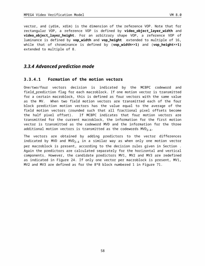
MPEG4 Video Verification Model VM 8.0
· DC coefficients of Type 1 blocks are quantized by Nonlinear Scaler for Type 1
· DC coefficients of Type 2 blocks are quantized by Nonlinear Scaler for Type 2
The nonlinear quantization strategy provides an effective compromise between the bits savings properties of DC scaler of 2Qp and its consequence on visual picture quality. The key features of this technique are as follows.
· Separate DC Scaler for Luminance and Chrominance, with smaller DC Scaler for chrominance as compared to luminance
· DC coefficient scaling method based on a non linear function of quantizer Qp used for the coded macroblock
· DC Scaler is derived to minimize the visibility of artifacts by heuristic experimentation and noise visibility thresholding
· The nonlinear function used for DC coefficient scaling is approximated by a number of piecewise linear functions based on a certain number of predetermined breakpoints.
· A separate set of reconstruction rules depending on either the quantizer Qp being used or a constant (such as, 8), with separate reconstruction rules for each quantizer range identified by the breakpoints.
Table 9 specifies the nonlinear dc_scaler expressed in terms of piece-wise linear characterstics.
When applied to grayscale alpha masks, the maximum limit (QP=31) of ??? is removed.
Component:Type dc_scaler for Quantizer (Qp) range
1 through 4 5 through 8 9 through 24 25 through 31
Luminance: Type1 8 2Qp Qp+8 2Qp-16
Chrominance: Type2 8 (Qp+13)/2 Qp-6
Table 9 Nonlinear scaler for DC coefficients of DCT blocks, expressed in terms of relation with Qp
The forward quantization is performed as follows.
level = dc_coef//dc_scaler
The reconstructed DC values are computed as follows.
dc_rec = dc_scaler*level
3.4.6.1.2 AC CoefficientsAC coefficients ac[i][j] are first quantised by individual quantization factors,
ac~[i][j] = (16 * ac[i][j]) //wI[i][j]
where wI[i][j] is the [i][j]th element of the default Intra quantizer matrix, which for this VM carries a value of 16 for all values; this is referred to as flat matrix.
The resulting ac~[i][j] is limited to the range [-2048, 2047].
An example of non-flat intra quantization matrix which can be alternatively used as default is provided for guidance in Figure 32 and if used should be clearly stated in core experiment comparisons against VM.
8 17 18 19 21 23 25 27
17 18 19 21 23 25 27 28
20 21 22 23 24 26 28 30
21 22 23 24 26 28 30 32
58
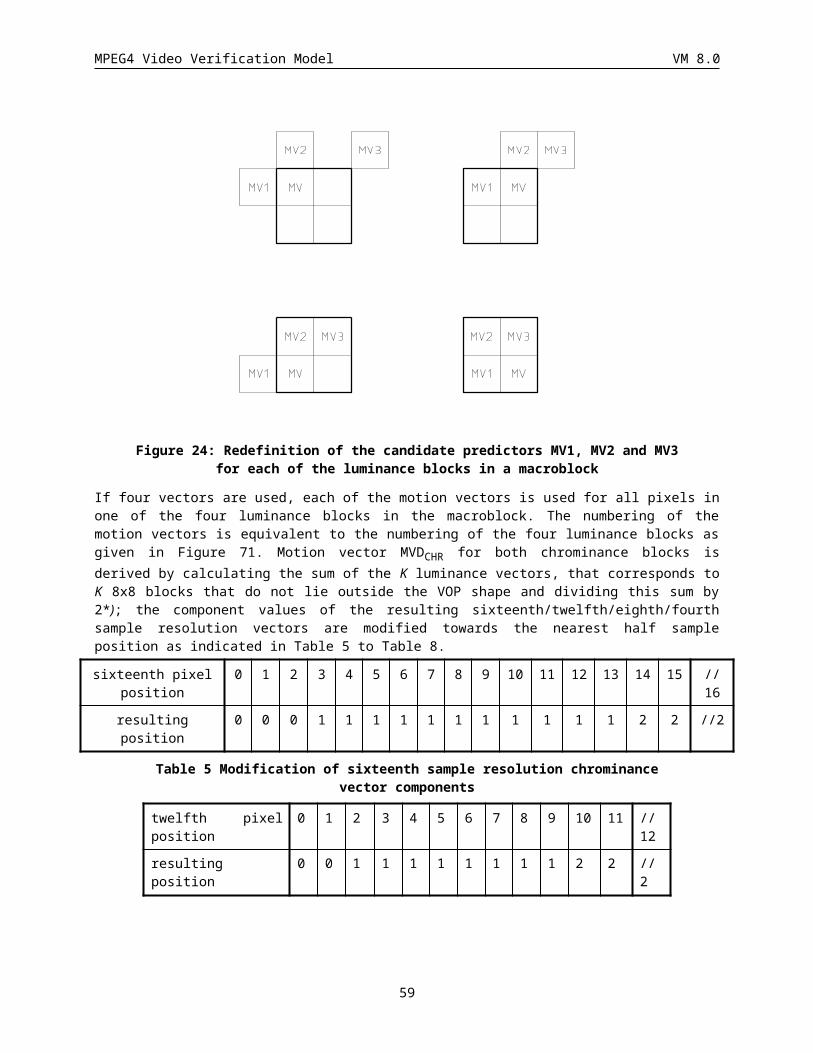
MPEG4 Video Verification Model VM 8.0
22 23 24 26 28 30 32 35
23 24 26 28 30 32 35 38
25 26 28 30 32 35 38 41
27 28 30 32 35 38 41 45
Figure 32: Example Intra quantizer matrix
The step-size for quantizing the scaled DCT coefficients, ac~[i][j], is derived from the quantization parameter, QP.
The quantized level QAC[i][j] is given by:
QAC[i][j] = (ac~[i][j] + sign(ac~[i][j])*((p * QP) // q)) / (2*QP)
where, QAC [i][j] is limited to the range [-127..127].
For this VM p=3, and q = 4.
3.4.6.2 Quantization of Non Intra Macroblocks
Forward Quantization:Non-intra macroblocks in P- and B- VOPs are quantized with a uniform quantizer that has a dead-zone about zero. The default quantization matrix carries a value of 16 for each entry and is referred to as flat matrix.
An example of non-flat nonintra quantization matrix which can be alternatively used as default is provided for guidance in Figure 33 and if used should be clearly stated in core experiment comparisons against VM.
16 17 18 19 20 21 22 23
17 18 19 20 21 22 23 24
18 19 20 21 22 23 24 25
19 20 21 22 23 24 26 27
20 21 22 23 25 26 27 28
21 22 23 24 26 27 28 30
22 23 24 26 27 28 30 31
23 24 25 27 28 30 31 33
Figure 33: Example of non-intra quantizer matrix
The step-size for quantizing both the scaled DC and AC coefficients is derived from the quantization parameter, QP.
ac~[i][j] = (16 * ac[i][j]) // wN[i][j]
where
wN[i][j] is the non-intra quantizer matrix
QAC[i][j] = ac~[i][j] / (2*QP)
QAC [i][j] is limited to the range [-127:127].
59
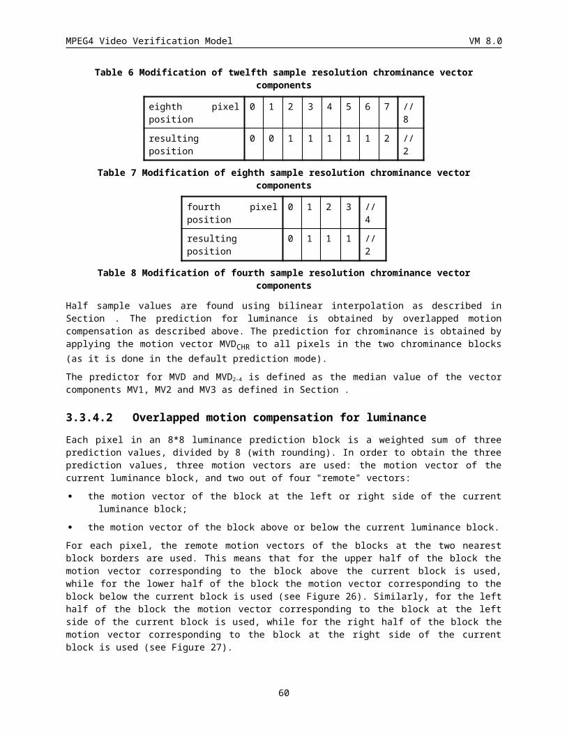
MPEG4 Video Verification Model VM 8.0
3.4.6.3 Inverse Quantization of Intra and Non Intra MacroblocksThe two-dimensional array of coefficients, QF[v][u], is inverse quantised to produce the reconstructed DCT coefficients. This process is essentially a multiplication by the quantiser step size. The quantiser step size is modified by two mechanisms; a weighting matrix is used to modify the step size within a block and a scale factor is used in order that the step size can be modified at the cost of only a few bits (as compared to encoding an entire new weighting matrix).
Inverse Quantisation Arithmetic
Saturation
QF[v][u] F''[v][u] F'[v][u] F[v][u]
quant_scale_code
W[w][v][u]
Mismatch Control
Figure 34: Inverse quantisation process
Figure 34 illustrates the overall inverse quantisation process. After the appropriate inverse quantisation arithmetic the resulting coefficients, F''[v][u], are saturated to yield F'[v][u] and then a mismatch control operation is performed to give the final reconstructed DCT coefficients, F[v][u].
NOTE - Attention is drawn to the fact that the method of achieving mismatch control in this specification is identical to that employed by ISO/IEC 13818-2.
3.4.6.3.1 Intra DC coefficientThe DC coefficients of intra coded blocks shall be inverse quantised in a different manner to all other coefficients.
In intra blocks F’’[0][0] shall be obtained by multiplying QF[0][0] by a constant multiplier,
The reconstructed DC values are computed as follows.
F’’[0][0] = dc_scaler* QF[0][0]
3.4.6.3.2 Other coefficientsAll coefficients other than the DC coefficient of an intra block shall be inverse quantised as specified in this clause.
3.4.6.4 Weighting matricesTwo weighting matrices are used. One shall be used for intra macroblocks and the other for non-intra macroblocks. Each matrix has a default set of values which may be overwritten by down-loading a user defined matrix.
Let the weighting matrices be denoted by W[w][v][u] where w takes the values 0 to 1 indicating which of the matrices is being used. W[0][v][u] is for intra macroblocks, and W[1][v][u] is for non-intra macroblocks.
60
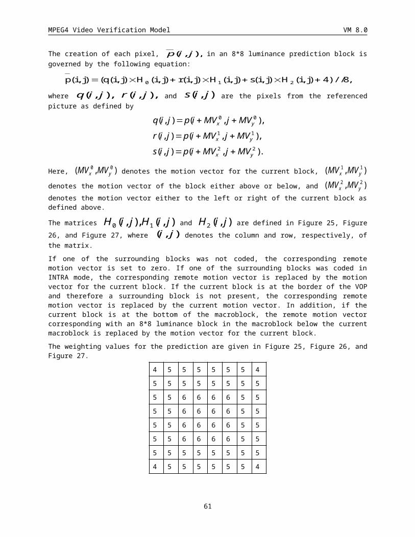
MPEG4 Video Verification Model VM 8.0
3.4.6.4.1 Reconstruction formulaeThe following equation specifies the arithmetic to reconstruct F''[v][u] from QF[v][u] (for all coefficients except intra DC coefficients).
F ' ' [v][u ]((2QF[v][u]k )W[w][v][u]quantiser _ scale) 32where :
k 0 intra blocks
Sign(QF[v][u]) non - intra blocks
NOTE - The above equation uses the “/” operator as defined in 4.1.
3.4.6.5 SaturationThe coefficients resulting from the Inverse Quantisation Arithmetic are saturated to lie in the range [ 2048:2047]. Thus:
F ' [v][u]2047 F ' ' [v][u] 2047
F ' ' [v][u] 2048F ' ' [v][u ]2047 2048 F ' ' [v][u] 2048
3.4.6.6 Mismatch controlMismatch control shall be performed by any process equivalent to the following. Firstly all of the reconstructed, saturated coefficients, F'[v][u] in the block shall be summed. This value is then tested to determine whether it is odd or even. If the sum is even then a correction shall be made to just one coefficient; F[7][7]. Thus:
sum F ' [v][u ]u0
u8
v0
v 8
F[v][u] F ' [v][u] for all u , v except u = v = 7
F[7][7] F ' [7][7] if sum is odd
F ' [7][7] 1 if F ' [7][7] is oddF ' [7][7]1 if F ' [7][7] is even
if sum is even
NOTES -
1 It may be useful to note that the above correction for F[7][7] may simply be implemented by toggling the least significant bit of the twos complement representation of the coefficient. Also since only the “oddness” or “evenness” of the sum is of interest an exclusive OR (of just the least significant bit) may be used to calculate “sum”.
2 Warning. Small non-zero inputs to the IDCT may result in zero output for compliant IDCTs. If this occurs in an encoder, mismatch may occur in some pictures in a decoder that uses a different compliant IDCT. An encoder should avoid this problem and may do so by checking the output of its own IDCT. It should ensure that it never inserts any non-zero coefficients into the bitstream when the block in question reconstructs to zero through its own IDCT function. If this action is not taken by the encoder, situations can arise where large and very visible mismatches between the state of the encoder and decoder occur.
3.4.6.7 SummaryIn summary the inverse quantisation process is any process numerically equivalent to:
61
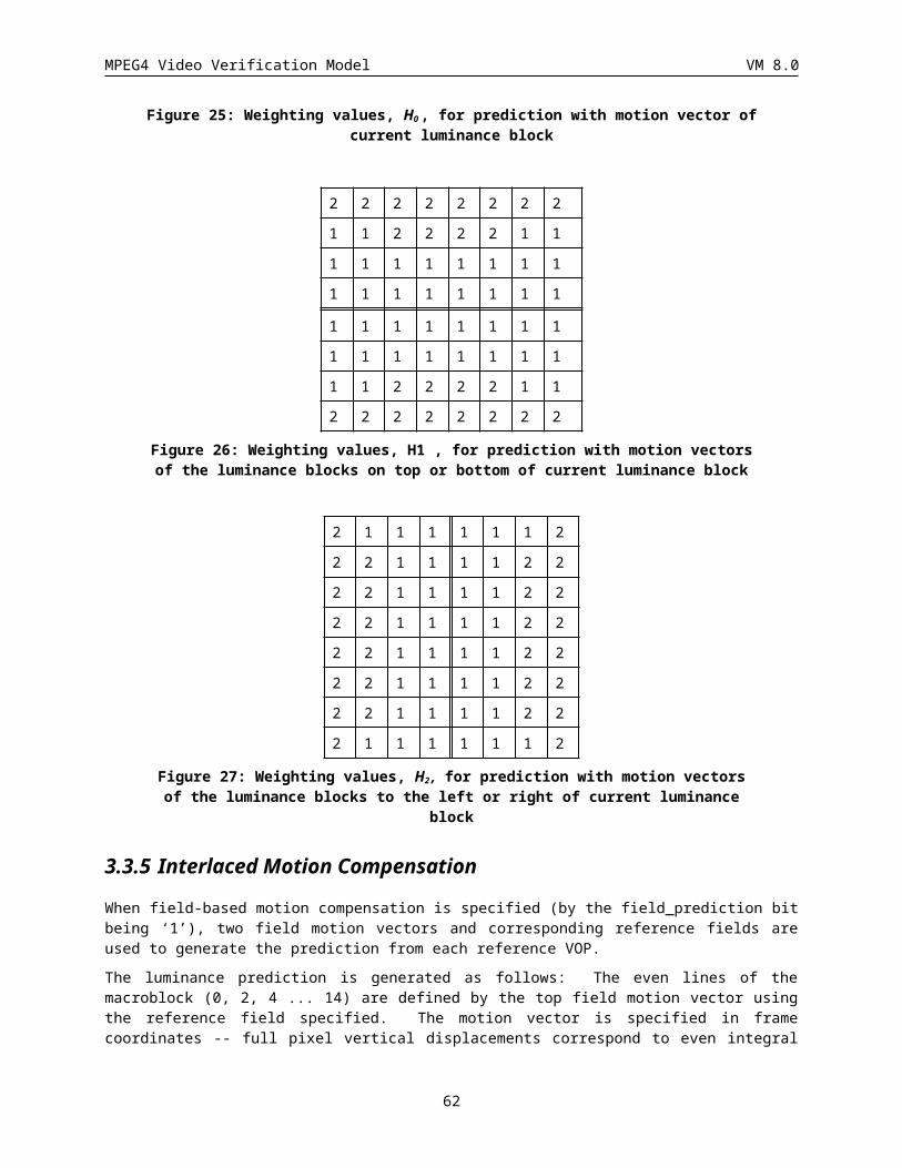
MPEG4 Video Verification Model VM 8.0
for (v=0; v<8;v++) {for (u=0; u<8;u++) {
if ( (u==0) && (v==0) && (macroblock_intra) ) {F''[v][u] = dc_scaler * QF[v][u];
} else {if ( macroblock_intra ) {
F''[v][u] = ( QF[v][u] * W[0][v][u] * quantiser_scale * 2 ) / 32;} else {
F''[v][u] = ( ( ( QF[v][u] * 2 ) + Sign(QF[v][u]) ) * W[1][v][u]* quantiser_scale ) / 32;
}}
}}
sum = 0;for (v=0; v<8;v++) {
for (u=0; u<8;u++) {if ( F’'[v][u] > 2047 ) {
F’[v][u] = 2047;} else {
if ( F’'[v][u] < -2048 ) {F’[v][u] = -2048;
} else {F’[v][u] = F'‘[v][u];
}}
sum = sum + F’[v][u];F[v][u] = F’[v][u];}
}
if ((sum & 1) == 0) {if ((F[7][7] & 1) != 0) {
F[7][7] = F'[7][7] - 1;} else {
F[7][7] = F'[7][7] + 1;}
}
3.4.7 Intra DC and AC Prediction for I-VOP and P-VOP
3.4.7.1 Adaptive DC Prediction The adaptive DC prediction method of this VM involves selection of either the QDC value of immediately previous block or that of the block immediately above it (in the previous row of blocks). This adaptive selection of the DC prediction direction is based on comparison of the horizontal and vertical QDC value gradients around the block whose QDC value is to be coded.
62
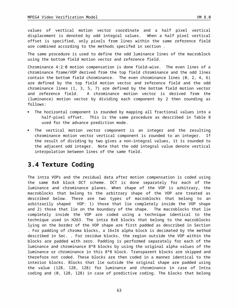
MPEG4 Video Verification Model VM 8.0
Figure 35 shows three surrounding blocks to the block whose QDC value is to be coded. Assume, ‘X’, ‘A’, ‘B’ and ‘C’ correspondingly refer to the current block, the previous block, the block above and to the left, and the block immediately above as shown.
A
B C D
X MacroblockY
or or
Figure 35 Previous neighboring blocks used in DC prediction
The dc values ‘dc’ obtained after DCT are first quantized by 8 to generate ‘QDC’ values.
QDC=dc//8
The QDC value of block ‘X’, QDCX, is predicted by either the QDC value of block ‘A’, QDCA, or the QDC value of the block ‘C’, QDCC, based on the comparison of horizontal and vertical gradients as follows. if (|QDCA - QDCB| < |QDCB - QDCC|)
QDCX’ = QDCC
elseQDCX’ = QDCA
The differential DC is then obtained by subtracting the DC prediction, QDCX’ from QDC of block ‘X’.
DC prediction the following For simple rules are used:
· If any of the blocks A, B or C are outside of the VOP boundary, or they do not belong to an intra coded macroblock, their QDC values are assumed to take a value of 2 (bits_per_pixel-1). and are used to compute prediction values.
· In context of computing QDC prediction for block ‘X’, if the absolute value of a horizontal gradient (|QDCA
- QDCB|) is less than the absolute value of a vertical gradient (|QDCB - QDCC|), then the prediction is the QDC value of block ‘C’, otherwise, QDC value of block ‘A’ is used for prediction. This process is independently repeated for every block of a macroblock using appropriate immediately horizontally adjacent block ‘A’ and immediately vertically adjacent block ‘C’.
· DC predictions are performed similarly for the luminance and each of the two chrominance components.
3.4.7.2 Adaptive AC Coefficient Prediction
3.4.7.2.1 Prediction of First Row or First Column of AC CoefficientsEither coefficients from the first row or the first column of a previous coded block are used to predict the co-sited coefficients of the current block. On a block basis, the best direction (from among horizontal and vertical directions) for DC coefficient prediction is also used to select the direction for AC coefficients prediction; thus, within a macroblock, for example, it becomes possible to predict each block independently from either the horizontally adjacent previous block or the vertically adjacent previous block. The AC coefficients prediction is ilustrated in Figure 36.
63
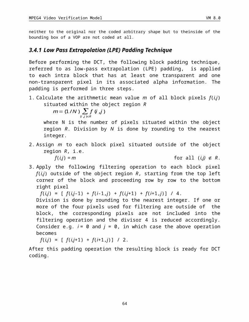
MPEG4 Video Verification Model VM 8.0
A
B
X
DC
or
Macroblock
Y
or
Figure 36 Previous neighboring blocks and coefficients used in AC prediction
3.4.7.2.2 Q-step ScalingTo compensate for differences in the quantization of previous horizontaly adjacent or vertically adjacent blocks used in AC prediction of the current block, scaling of prediction coefficients becomes necessary. Thus the prediction is modified so that the predictor is scaled by the ratio of the current quantisation stepsize and the quantisation stepsize of the predictor block. The definition is given in the equations below.
If block ‘A’ was selected as the predictor for the block for which coefficient prediction is to be performed, we calculate the horizontal AC prediction as follows.
X
AAiXi QP
QPQACQAC 0
'0
If block ‘C’ was selected as the predictor for the block for which coefficient prediction is to be performed, we calculate the vertical AC prediction as follows.
X
CjCjX QP
QPQACQAC
0
'0
If block ‘A’ or block ‘C’ are outside of the VOP, then the corresponding QP values are assumed to be equal to QPx.
3.4.7.2.3 AC Prediction Enable/Disable Mode Decision (ACpred_Flag)In the cases when AC coefficient prediction results in a larger magnitude error signal as compared to the original signal, it is desirable to disable AC prediction. However, the overhead is excessive if AC prediction is switched on or off every block so AC prediction switching is performed on macroblock basis.
If block ‘A’ was selected as the predictor for the block for which coefficient prediction is to be performed, we calculate a criterion, S, as follows.
64
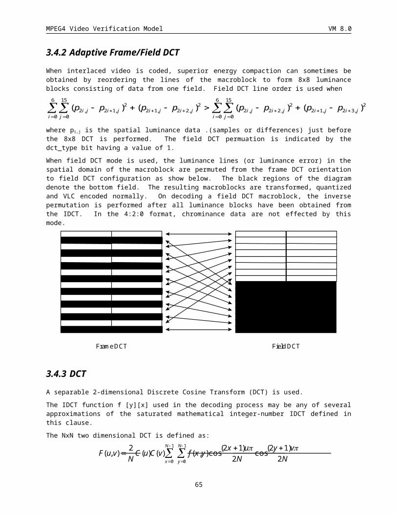
MPEG4 Video Verification Model VM 8.0
|||| '0
7
10
7
10 Xi
iXi
iXi QACQACQACS
If block ‘C’ was selected as the DC predictor for the block for which coefficient prediction is to be performed, we calculate S as follows.
|||| '0
7
10
7
10 jX
jjX
jjX QACQACQACS
Next for all blocks in the macroblock for which a common decision is to be made, a single S is calculated and the ACpred_flag is either set/ reset to enable/disable AC prediction as follows.
if (S ³ 0) ACpred_flag=1 (enable AC Prediction)
else ACpred_flag=0 (disable AC Prediction)
For AC prediction the following simple rules are used:
If any of the blocks A, B or C are outside of the VOP boundary or are do not belong to an intra coded macroblock, their QAC values are assumed to take a value of 0 and are used to compute prediction values.
AC predictions are performed similarly for the luminance and each of the two chrominance components using the direction identified by the corresponding direction of DC prediction.
The process for ac_dc_ prediction for alpha plane is similar to that of texture as described above.
3.4.8 VLC encoding of quantized transform coefficients
3.4.8.1 VLC encoding of intra MbsTwo scans in addition to the zigzag scan are employed; all three scans are shown in Figure 37.
For intra predicted blocks, if ACpred_flag=0, zigzag scan is selected for all blocks in a macroblock, otherwise, DC prediction direction is used to select a scan on block basis. For instance if the DC prediction refers to the horizontally adjacent block, alternate-vertical scan is selected for the current block, otherwise (for DC prediction referring to vertically adjacent block), alternate-horizontal scan is used for the current block.
For non intra blocks, the 8x8 blocks of transform coefficients are scanned with “zigzag” scanning as listed in Figure 37.0 1 2 3 10 11 12 13 0 4 6 20 22 36 38 52 0 1 5 6 14 15 27 28
4 5 8 9 17 16 15 14 1 5 7 21 23 37 39 53 2 4 7 13 16 26 29 42
6 7 19 18 26 27 28 29 2 8 19 24 34 40 50 54 3 8 12 17 25 30 41 43
20 21 24 25 30 31 32 33 3 9 18 25 35 41 51 55 9 11 18 24 31 40 44 53
22 23 34 35 42 43 44 45 10 17 26 30 42 46 56 60 10 19 23 32 39 45 52 54
36 37 40 41 46 47 48 49 11 16 27 31 43 47 57 61 20 22 33 38 46 51 55 60
38 39 50 51 56 57 58 59 12 15 28 32 44 48 58 62 21 34 37 47 50 56 59 61
52 53 54 55 60 61 62 63 13 14 29 33 45 49 59 63 35 36 48 49 57 58 62 63
Figure 37 (a) Alternate-Horizontal scan (b) Alternate-Vertical (MPEG-2) scan(c) Zigzag scan
A three dimensional variable length code is used to code transform coefficients. An EVENT is a combination of three parameters:
LAST 0: There are more nonzero coefficients in the block.
1: This is the last nonzero coefficient in the block.
65
MPEG4 Video Verification Model VM 8.0
RUN Number of zero coefficients preceding the current nonzero coefficient.
LEVEL Magnitude of the coefficient.
The most commonly occurring combinations of (LAST, RUN, LEVEL) are coded with variable length codes given in Appendix B. The remaining combinations of (LAST, RUN, LEVEL) are coded with a 22 bit word consisting of :
ESCAPE 7 bit
LAST 1 bit (0: Not last coefficient, 1: Last nonzero coefficient)
RUN 6 bit
LEVEL 8 bit
The code words for these fixed length ESCAPE codes are described in Appendix A
· For Intra macroblock chroma AC Coefficients, the VLC used is the same as that used for Intra AC luminance coefficients
(VLC tables Table 62, Table 63 label needs to be modified).
3.4.8.2 Intra DC Coefficient Coding by Switching between DC Intra VLC and AC Intra VLC
· At the VOP layer, using quantizer value as the threshold, a 3 bit code (intra_dc_vlc_thr) allows switching between 2 VLCs (DC Intra VLC and AC Intra VLC) when coding DC coefficients of Intra macroblocks
intra_dc_vlc_thr 3 uimsbf
intra dc_vlc_thr is a 3-bit code allows a mechanism to switch between two VLC’s for coding of Intra DC coefficients as per the following table.
index intra_dc_vlc_thr meaning code
0 Use Intra DC VLC for entire VOP 000
1 Switch to Intra AC VLC at running Qp >=13 001
2 Switch to Intra AC VLC at running Qp >=15 010
3 Switch to Intra AC VLC at running Qp >=17 011
4 Switch to Intra AC VLC at running Qp >=19 100
5 Switch to Intra AC VLC at running Qp >=21 101
6 Switch to Intra AC VLC at running Qp >=23 110
7 Use Intra AC VLC for entire VOP 111
Table 10 Meaning of intra_dc_vlc_thr
Where running Qp is defined as Qp value used for immediately previous coded macroblock.
Note: When the intra AC-VLC is turned on, INTRA-DC transform coefficients are not handled separately any more, but treated the same as all AC coefficients. That means a zero INTRA-DC will not be coded but will simply increase the run for the following AC-coefficients. The definitions of MCBPC and CBPY in paragraph are changed accordingly.
66
MPEG4 Video Verification Model VM 8.0
3.4.8.3 VLC encoding of inter MBsThe 8x8 blocks of transform coefficients are scanned with “zigzag” scanning as listed in Figure 38.
1 2 6 7 15 16 28 29
3 5 8 14 17 27 30 43
4 9 13 18 26 31 42 44
10 12 19 25 32 41 45 54
11 20 24 33 40 46 53 55
21 23 34 39 47 52 56 61
22 35 38 48 51 57 60 62
36 37 49 50 58 59 63 64
Figure 38: Zigzag scanning pattern.
A three dimensional variable length code is used to code transform coefficients. An EVENT is a combination of three parameters:
LAST 0: There are more nonzero coefficients in the block.
1: This is the last nonzero coefficient in the block.
RUN Number of zero coefficients preceding the current nonzero coefficient.
LEVEL Magnitude of the coefficient.
The most commonly occurring combinations of (LAST, RUN, LEVEL) are coded with variable length codes given in Appendix A. The remaining combinations of (LAST, RUN, LEVEL) are coded with a 22 bit word consisting of :
ESCAPE 7 bit
LAST 1 bit (0: Not last coefficient, 1: Last nonzero coefficient)
RUN 6 bit
LEVEL 8 bit
The code words for these fixed length ESCAPE codes are described in section .
3.5 Prediction and Coding of B-VOPsMacroblocks in B-VOPs can be coded either using H.263 like B-block coding or by MPEG-1 like B-picture macroblock coding. The main difference is in the amount of motion vector and quantization related overhead needed. The MBTYPE with H.263 like B-block coding is referred to as direct prediction, besides which, the forward, the backward and the interpolated prediction modes of MPEG-1 B-pictures are supported. The syntax and semantics for macroblock and block layer for B-VOPs are presented in section .The encoding issues for B-VOPs are discussed next.
3.5.1 Direct CodingThis coding mode uses direct bidirectional motion compensation derived by extending H.263 approach of employing P-picture macroblock motion vectors and scaling them to derive forward and backward motion vectors for macroblocks in B-picture. This is the only mode which makes it possible to use motion vectors on 8x8 blocks, of course, this is only possible when the co-located macroblock in the following P-VOP uses 8x8 MV mode. As
67
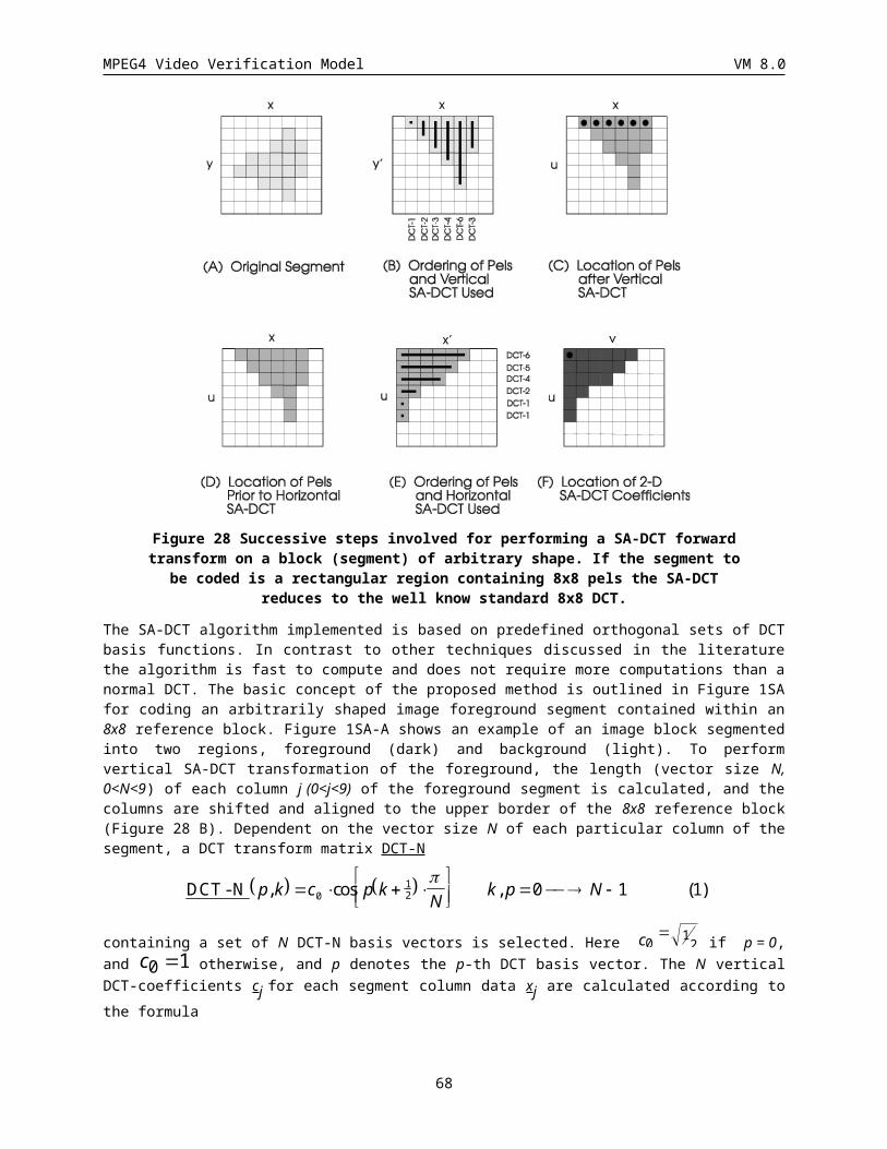
MPEG4 Video Verification Model VM 8.0
per H.263, using B-frame syntax, only one delta motion vector is allowed per macroblock. Figure 39 shows scaling of motion vectors.
The first extension of the H.263 approach is that bidirectional predictions can be made for a full block/macroblock as in MPEG-1. The second extension of H.263 is that instead of allowing interpolation of only one intervening VOP, more than one VOPs can be interpolated. Of course, if the prediction is poor due to fast motion or large interframe distance, other motion compensation modes can be chosen.
MVF = MV/3 + MVDMVB = -(2MV)/3 if MVD is zero
Note: MVD is the delta vector given by MVDBMVB = MVF-MV if MVD is nonzero
0 1 2 3
MV
Figure 39: Direct Bidirectional Prediction
3.5.1.1 Calculation of vectorsThe calculation of forward and backward motion vectors involves linear scaling of the collocated block in temporally next P-VOP, followed by correction by a delta vector, and is thus practically identical to the procedure followed in H.263. The only slight change is that here we are dealing with VOPs instead of pictures, and instead of only a single B-picture between a pair of reference pictures, multiple B-VOPs are allowed between a pair of reference VOPs. As in H.263, the temporal reference of the B-VOP relative to difference in the temporal reference of the pair of reference VOPs is used to determine scale factors for computing motion vectors which are corrected by the delta vector. Furthermore, colocated Mbs are defined as Mbs with the same index when possible, otherwise the direct mode is not used.
The forward and the backward motion vectors are MVF and MVB and are given in half sample units as follows.
MVF = (TRB x MV) / TRD + MVD
MVB = ((TRB - TRD) x MV) / TRD if MVD is equal to 0
MVB = MVF - MV if MVD is not equal to 0
Where MV is the direct motion vector of a macroblock in P-VOP with respect to a reference VOP, TR B is the difference in temporal reference of the B-VOP and the previous reference VOP. TR D is the difference in temporal reference of the temporally next reference VOP with temporally previous reference VOP, assuming B-VOPs or skipped VOPs in between.
3.5.1.2 Generating Prediction BlockThe process of generating a prediction block is fairly trivial and simply consists of using computed forward and backward motion vectors to obtain appropriate blocks from reference VOPs and averaging these blocks. Irrespective of whether the direct prediction motion vectors are derived by scaling of a single motion vector or four 8x8 motion vectors per block, motion compensation is performed individually on 8x8 blocks to generate a macroblock. In case for a macroblock only a single motion vector was available to compute direct prediction motion vector, it is simply repeated for each of the 8x8 blocks forming the macroblock. The main difference with H.263 is that there are no constraints in the amount of region within a block that can be bidirectionally predicted; each entire macroblock can be bidirectionally predicted. It should be noted that if if the next reference VOP is an I-VOP instead of a P-VOP, then the MV vectors are by default ‘0’. Therefore, the direct mode need not be disabled for the B-VOPs before the I-VOP.
68
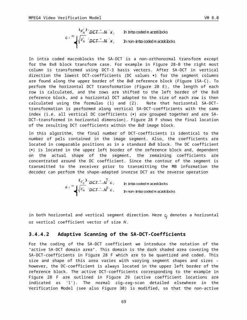
MPEG4 Video Verification Model VM 8.0
The direct coding mode does not allow quantizer change and thus the quantizer value for previous coded macroblock is used.
3.5.1.3 Interlaced Direct Coding ModeProgressive direct coding mode is used whenever the macroblock at the same location in the future anchor picture is coded as (1) a 16x16 (frame) macroblock, (2) an intra macroblock or (3) an 8x8 (advanced prediction) macroblock. The extension to interlaced video described below is used whenever the corresponding macroblock of the future anchor VOP is a field motion compensated macroblock.
Interlaced direct mode forms the prediction macroblock separately for the top and bottom fields. The four field motion vectors of a bi-directional field motion compensated macroblock are calculated from the motion vectors of the corresponding macroblock of the future anchor picture. Once the motion vectors and reference field are determined, the macroblock is considered to be a bi-directional field predicted macroblock. Only one delta motion vector (used for both fields) occurs in the bitstream for the field predicted macroblock.
The top field prediction is based on the top field motion vector of the P-VOP macroblock of the future anchor picture. The past reference field is the reference field selected by the corresponding macroblock of the future anchor picture for the top field. Analogously, the bottom field predictor is the average of pixels obtained from the future anchor’s bottom field and the past anchor field referenced by the bottom field motion vector of the corresponding macroblock of the future anchor picture.
The motion vectors for field i (top or bottom) are calculated by
MVf,i = (TRB,I * MVi) / TRD,I + MVD
MVb,I = (MVD == 0) ? (((TRB - TRD) * MVi) / TRD,I) : (MVf,I - MVi)
All of the MVs are 2 dimensional vectors. The definition of the quantities above are
MVf,I Forward motion vector for field i. The reference field is the reference field of MVi.
MVb,I Backward motion vector for field i. The reference field is i.
69
TRD,i
TRB,i
MVi
MVF,i MBB,i
Past
Anchor
Current
VOP
Future
Anchor
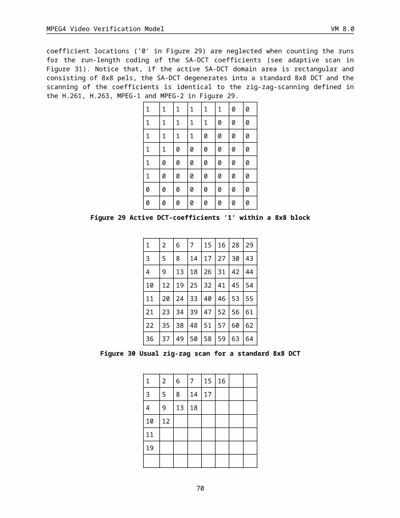
MPEG4 Video Verification Model VM 8.0
MVi Field motion for field i of the macroblock at the same location as the current macroblock in the future anchor VOP (note that the future anchor VOP is always a P-VOP for field direct mode; if the future anchor was an I-VOP, the motion vector would be 0 and 16x16 progressive direct mode would be used).
TRB,i Temporal distance in fields between the past reference field for field i and field i of the current B-VOP.
TRD,i Temporal distance in fields between the past reference field and the future reference field for the current VOP’s field i.
The calculation of TRB,i and TRD,i depends not only on the current field, reference field, and frame temporal references, but also on whether the current video is top field first or bottom field first.
TRD,i = 2*(TRfuture - TRpast) + dTRB,i = 2*(TRcurrent - TRpast) + d
where TRfuture, TRcurrent, and TRpast are the frame number of the future, current and past frames in display order, and d is given by the following table:
Top field first Bottom field first
Top field reference
Bottom field reference
Top field d
Bottom field d
Top field d
Bottom field d
0 0 0 -1 0 1
0 1 0 0 0 0
1 0 1 -1 -1 1
1 1 1 0 -1 0
Both interlaced and progressive direct coding modes do not allow quantizer change and thus the quantizer value for previous coded macroblock is used.
3.5.2 Forward CodingForward coding mode uses forward motion compensation in the same manner as in MPEG-1/.2 with the difference that a VOP is used for prediction instead of a picture. Only one motion vector in half sample units is employed for a 16x16 macroblock being coded. Chrominance vectors are derived by scaling of luminance vectors as in MPEG-1/2.
This coding mode also allows switching of quantizer from the one previously in use. Specification of DQUANT, a differential quantizer involves a 2-bit overhead as discussed earlier.
3.5.3 Backward CodingBackward coding mode uses backward motion compensation in the same manner as in MPEG-1/2 with the difference that a VOP is used for prediction instead of a picture. Only one motion vector in half sample units is employed for a 16x16 macroblock being coded. Chrominance vectors are derived by scaling of luminance vectors as in MPEG-1/2.
This coding mode also allows switching of quantizer from the one previously in use. Specification of DQUANT, a differential quantizer involves a 2-bit overhead as discussed earlier.
3.5.4 Bidirectional CodingBidirectional coding mode uses interpolated motion compensation in the same manner as in MPEG-1/.2 with the difference that a VOP is used for prediction instead of a picture. Two motion vectors in half sample units are employed for a 16x16 macroblock being coded. Chrominance vectors are derived by scaling of luminance vectors as in MPEG-1/2.
70
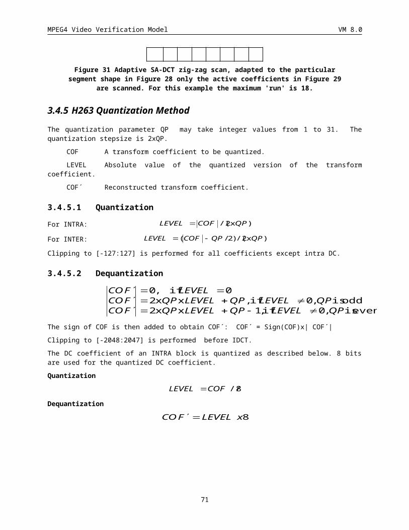
MPEG4 Video Verification Model VM 8.0
This coding mode also allows switching of quantizer from the one previously in use. Specification of DQUANT, a differential quantizer involves a 2-bit overhead as discussed earlier
3.5.5 Mode DecisionsSince, in B-VOPs, a macroblock can be coded in one of the four modes, we have to decide which mode is the best. At the encoder, motion compensated prediction is calculated by each of the four modes. Next, using each of the motion compensated prediction macroblocks SAD (sum of absolute differences) is computed between it and the macroblock to be coded. The MBTYPE mode is selected as follows
if (SADdirect -NB/2+1 <= min{SADinterpolate, SADbackward, SADforward})direct mode
else if (SADinterpolate <= min{SADinterpolate, SADbackward, SADforward}) interpolate mode
else if (SADbackward <= min{SADinterpolate, SADbackward, SADforward})backward mode
else forward mode
For interlaced B-VOPs, a macroblock can be coded using (1) direct coding, (2) 16x16 motion compensated (includes forward, backward & bidirectional modes), or (3) field motion compensation (includes forward, backward & bidirectional modes). The decision regarding coding mode of the macroblock is based on the minimum luminance half-sample SADs with respect to the decoded anchor pictures:
SADdir+b1,SADfor+b2,SADfor,fld+b3,SADbak+b2,SADbak,fld+b3,SADave+b3,SADave,fld+b4
where the subscripts ‘dir’, ‘for’, ‘bak’, ‘ave’ and ‘fld’ stand for direct mode, forward motion prediction, backward motion prediction, average (i.e., interpolated or bidirectional) motion prediction and field mode. The field SADs above are the sums of the top and bottom field SADs each with its own reference field and motion vector. The b i’s are bias values for the purpose of discriminating against the prediction modes which require more motion vectors:
Mode Nbr of MVs bi Bias
Direct 1 b1 -(Nb/2 + 1)
Frame Fwd 1 b2 0
Frame Bak 1 b2 0
Frame Ave 2 b3 (Nb/2 + 1)
Field Fwd 2 b3 (Nb/2 + 1)
Field Bak 2 b3 (Nb/2 + 1)
Field Ave 4 b4 (Nb/1 + 1)
3.5.6 Motion Vector CodingMotion vectors are to be coded differentially. Only vectors that are used for the selected prediction mode are actually coded. For forward and backward motion vectors in forward, backward and bidirectional mode the left neighboring vector of the same direction type is used as predictor. In case the current macroblock is located on the left edge of the VOP or no vector of the same direction type is present, the predictor is set to zero.
For interlaced B-VOP motion vector predictors, four prediction motion vectors (PMVs) are used:
Function PMV
Top field forward 0
Bottom field forward 1
71
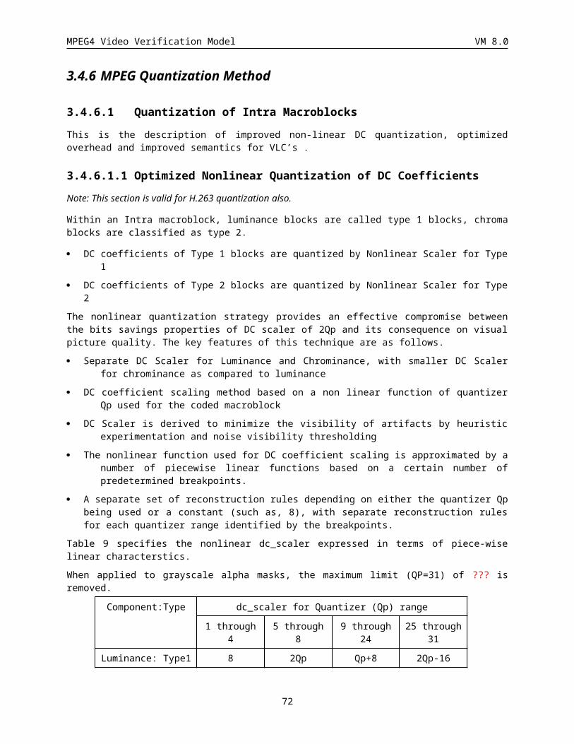
MPEG4 Video Verification Model VM 8.0
Top field backward 2
Bottom field backward 3
Table 11
These PMVs are used as follows for the different macroblock prediction modes:
Macroblock mode PMVs used
Direct none
Frame forward 0
Frame backward 2
Frame bidirectional 0,2
Field forward 0,1
Field backward 2,3
Field bidirectional 0,1,2,3
The PMVs used by a macroblock are set to the value of current macroblock motion vectors after being used. The prediction motion vectors are reset to zero at the beginning of each row of macroblocks. The predictors are not zeroed by skipped macroblocks or direct mode macroblocks.
For macroblocks coded in direct bidirectional mode no vector differences are transmitted. Instead, the forward and backward motion vectors are directly computed from the temporally consecutive P-vector as described in section . Additionally a single delta vector can be transmitted for direct mode. This vector is not predicted but directly applied to the equations in section .
3.6 Error Resilience
3.6.1 IntroductionMPEG-4 provides error robustness and resilience to allow accessing image or video information over a wide range of storage and transmission media. The error resilience tools developed for MPEG-4 can be divided into three major areas. These areas or categories include resynchronization, data recovery, and error concealment. It should be noted that these categories are not unique to MPEG-4, but instead have been used by many researchers working in the area error resilience for video. It is, however, the tools contained in these categories that are of interest, and where MPEG-4 makes its contribution to the problem of error resilience.
3.6.1.1 Resynchronization
Resynchronization tools, as the name implies, attempt to enable resynchronization between the decoder and the bitstream after a residual error or errors have been detected. Generally, the data between the synchronization point prior to the error and the first point where synchronization is reestablished, is discarded. If the resynchronization approach is effective at localizing the amount of data discarded by the decoder, then the ability of other types of tools which recover data and/or conceal the effects of errors is greatly enhanced.
The resynchronization approach adopted by MPEG-4, referred to as a packet approach, is similar to the Group of Blocks (GOBs) structure utilized by the ITU-T standards of H.261 and H.263. In
72
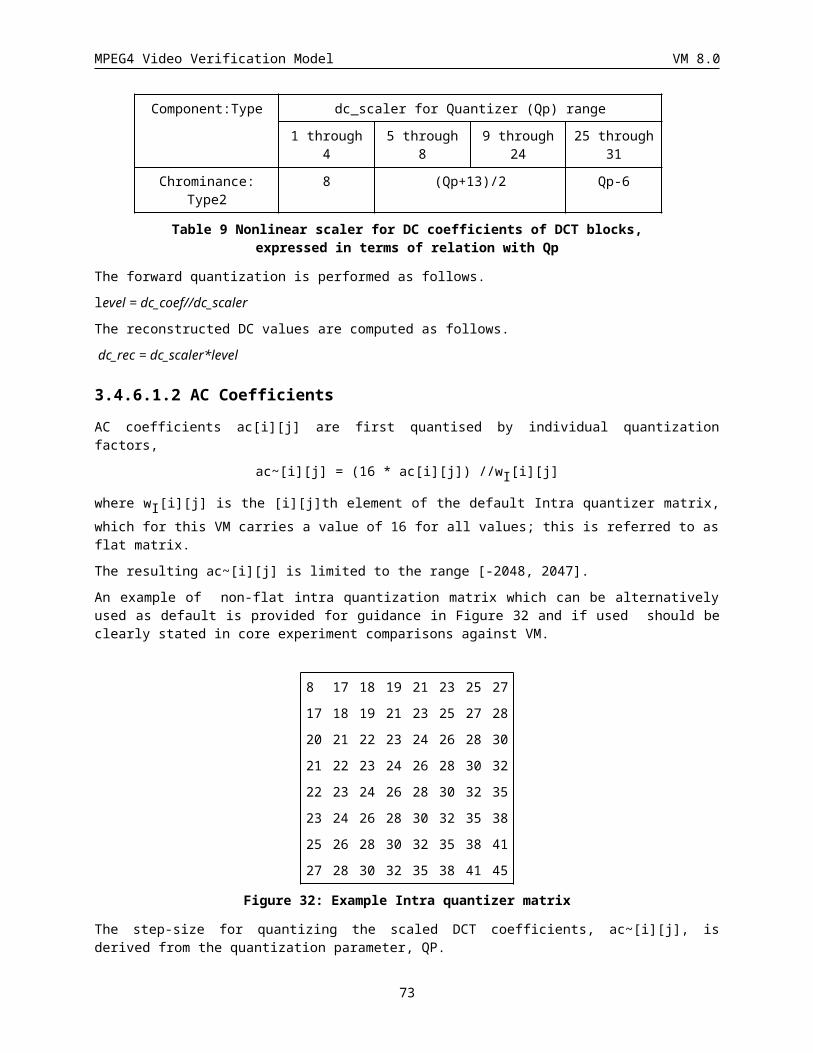
MPEG4 Video Verification Model VM 8.0
these standards a GOB is defined as one or more rows of macroblocks (MB). At the start of a new GOB, information called a GOB header is placed within the bitstream. This header information contains a GOB start code, which is different from a picture start code, and allows the decoder to locate this GOB. Furthermore, the GOB header contains information which allows the decoding process to be restarted (i.e., resynchronize the decoder to the bitstream and reset all coded data that is predicted).
The GOB approach to resynchronization is based on spatial resynchronization. That is, once a particular macroblock location is reached in the encoding process, a resynchronization marker is inserted into the bitstream. A potential problem with this approach is that since the encoding process is variable rate, these resynchronization markers will most likely be unevenly spaced throughout the bitstream. Therefore, certain portions of the scene, such as high motion areas, will be more susceptible to errors, which will also be more difficult to conceal.
The video packet approach adopted by MPEG-4, is based on providing periodic resynchronization markers throughout the bitstream. In other words, the length of the video packets are not based on the number of macroblocks, but instead on the number of bits contained in that packet. If the number of bits contained in the current video packet exceeds a predetermined threshold, then a new video packet is created at the start of the next macroblock.
A resynchronization marker is used to distinguished the start of a new video packet. This marker is distinguishable from all possible VLC code words as well as the VOP start code. Header information is also provided at the start of a video packet. Contained in this header is the information necessary to restart the decoding process and includes: the macroblock number of the first macroblock contained in this packet and the quantization parameter necessary to decode that first macroblock. The macroblock number provides the necessary spatial resynchronization while the quantization parameter allows the differential decoding process to be resynchronized. It should be noted that when utilizing the error resilience tools within MPEG-4, some of the compression efficiency tools are modified. For example, all predictively encoded information must be confined within a video packet so as to prevent the propagation of errors.
In conjunction with the video packet approach to resynchronization, a second method called fixed interval synchronization has also been adopted by MPEG-4. This method requires that VOP start codes and resynchronization markers (i.e., the start of a video packet) appear only at legal fixed interval locations in the bitstream. This helps to avoid the problems associated with start codes emulations. That is, when errors are present in a bitstream it is possible for these errors to emulate a VOP start code. In this case, when fixed interval synchronization is utilized the decoder is only required to search for a VOP start code at the beginning of each fixed interval. The fixed interval synchronization method extends this approach to be any predetermined interval.
3.6.1.2 Data Recovery
After synchronization has been reestablish, data recovery tools attempt to recover data that in general would be lost. These tools are not simply error correcting codes, but instead techniques which encode the data in an error resilient manner. For instance, one particular tool that has been endorsed by the Video Group is Reversible Variable Length Codes (RVLC). In this approach, the variable length code words are designed such that they can be read both in the forward as well as
73
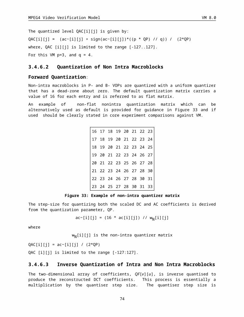
MPEG4 Video Verification Model VM 8.0
the reverse direction. Examples of such code words are 111, 101, 010. Code words such as 100 would not be used. Obviously, this approach reduces the compression efficiency achievable by the entropy encoder. However, the improvement in error resiliency is substantial.
An example illustrating the use of a RVLC is given in Figure XX. Generally, in a situation such as this, where a burst of errors has corrupted a portion of the data, all data between the two synchronization points would be lost. However, as shown in Figure XX , an RVLC enables some of that data to be recovered. It should be noted that the parameters, QP and HEC shown in Figure XX, represent the fields reserved in the video packet header for the quantization parameter and the header extension code, respectively.
Figure XX
3.6.1.3 Error Concealment
Error concealment is an extremely important component of any error robust video codec. Similar to the error resilience tools discussed above, the effectiveness of a error concealment strategy is highly dependent on the performance of the resynchronization scheme. Basically, if the resynchronization method can effectively localize the error then the error concealment problem becomes much more tractable. For low bitrate, low delay applications the current resynchronization scheme provides very acceptable results with a simple concealment strategy, such as copying blocks from the previous frame.
In recognizing the need to provide enhanced concealment capabilities, the Video Group has developed an additional error resilient mode that further improves the ability of the decoder to localize an error.
Specifically, this approach utilizes data partitioning by separating the motion and the texture. This approach requires that a second resynchronization marker be inserted between motion and texture information. If the texture information is lost, this approach utilizes the motion information to conceal these errors. That is, due to the errors the texture information is discarded, while the motion is used to motion compensate the previous decoded VOP.
74
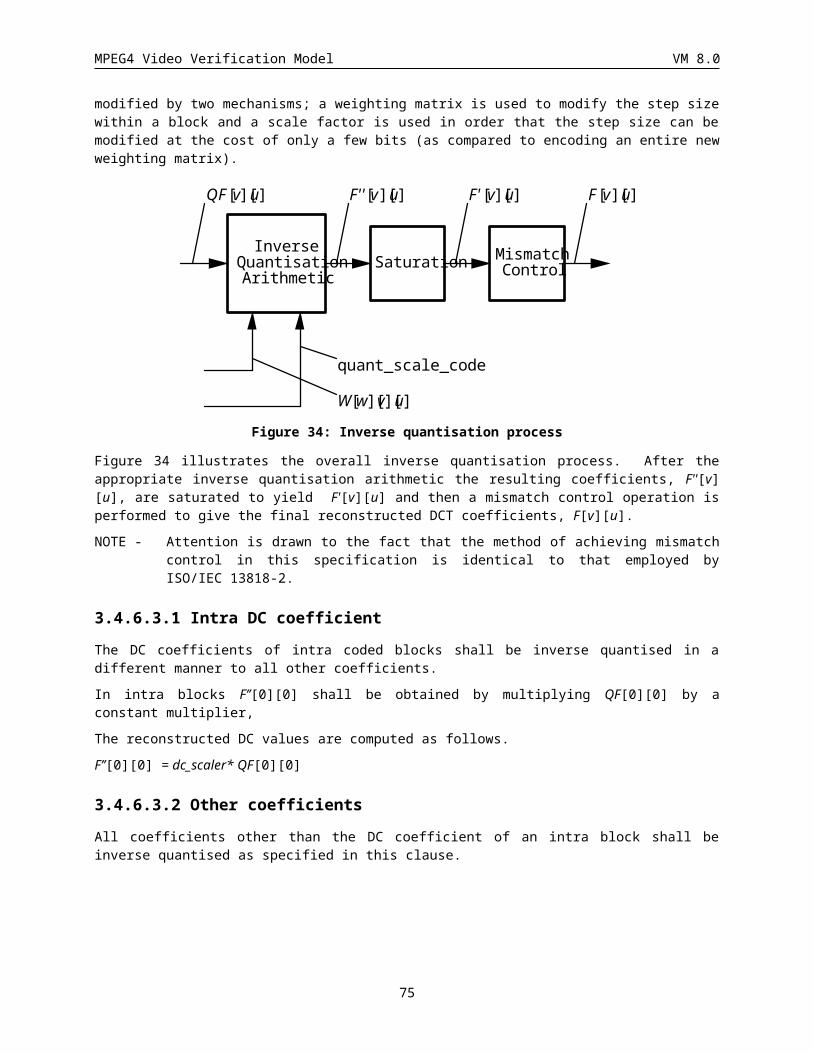
MPEG4 Video Verification Model VM 8.0
3.6.2 Recommended Modes of Operation
There are several different error resilience options available within the VM. These options, when used in various combinations, form different modes of error resilience operation. A summary of these various modes and their corresponding parameter settings are provided in Table X.3. A detailed description of the various error resilient modes and tools is provided in the remaining sections.
3.6.2.1 Low Complexity ModeThe low complexity mode of operation is provided as the basic mode of error resilience. The resynchronization marker, which is mandatory, provides resynchronization capabilities as well as the ability to verify that a video packet has received without errors. The RVLCs are optional in this mode. It is has been reported that the error detection capabilities (i.e., the decoder has a higher probability of receiving an illegal code word when errors are present) of the RVLC is better than the standard VLCs. Therefore, even though reverse decoding would not be performed the RVLC
Table X.3 Summary of Error Resilience Modes of operationMode VOP Type Resync Marker RVLC Data Partitioning
(Motion Marker)
Low
Complexity
I-VOP
P-VOP
X
X
x
x
Not Used
Not Used
Medium
Complexity
I-VOP
P-VOP
X
X
x
x
X
X
High
Complexity
I-VOP
P-VOP
X
X
X
X
X
X
X - indicates that the error resilience tool is mandatory. x indicates that the error resilience tool is optional.would still be utilized. Data partitioning would not be used in this mode. The following parameter settings must be made in order to utilize this mode:At VOL:· error_resilience_disabled = 0· data_partitioning = 0· reversible_VLC = optional
3.6.2.2 Medium Complexity ModeThe medium complexity mode of operation differs from the low complexity mode in that it utilizes data. That is, within each video packet, the motion data is separated from the texture data (this mode may also include shape). The boundary between the motion and texture information is identified through an additional marker called a “motion marker”. Additional error resilience over the low complexity mode is obtained, since the motion information becomes better isolated from errors which can cause it to become corrupted. If the texture information is corrupted the corresponding motion data can be used for motion compensated concealment.In this mode, the resynchronization marker is also mandatory. Again, do to their improved error detection capabilities, the RVLCs are available as an option in this mode. Since data partitioning is to be used, a motion marker will be inserted into the bitstream after the motion information. The following parameter settings must be made in order to utilize this mode:
75
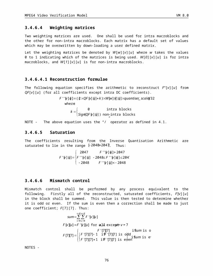
MPEG4 Video Verification Model VM 8.0
At VOL:· error_resilience_disabled = 0· data_partitioning = 1· reversible_VLC = optional
3.6.2.3 High Complexity ModeThe high complexity mode of operation utilizes all of the possible error resilience options. That is, in this mode the resynchronization marker, RVLC and data partitioning are all mandatory. It should be noted however, that this mode can still be successfully decoded by the decoder independent of whether it can decode the RVLCs in the reverse direction. The following parameter settings must be made in order to utilize this mode:At VOL:· error_resilience_disabled = 0· data_partitioning = 1· reversible_VLC = 1
3.6.2.4 Error Resilience Encoding Tools
3.6.2.4.1 Resynchronization Markers
When the “error_resilience_disabled” flag is set to zero, then a resync_marker field should be inserted by the encoder before the first macroblock after the number of bits output since the last resync_marker field exceeds a predetermined value. The value that should be used for this spacing is dependent on the anticipated error conditions of the transmission channel and compressed data rate. Suggested values for this spacing are provided in Table X.1. These values were determined through experimentation and provide good results across a wide range of error conditions. Specifically, the exact error conditions used to determine these suggested spacings are provided in Table X.2. It is highly recommended that users of MPEG-4’s error resilient tools adjust this spacing of the resynchronization markers to fit the error conditions of their particular channel.
Table X.2 Suggested Resynchronization Marker Spacing
Bit Rate (kbit/s) Spacing (bits)
0-24 480
25-48 736
49-128 1500
128-512 TBD
512-1000 TBD
76
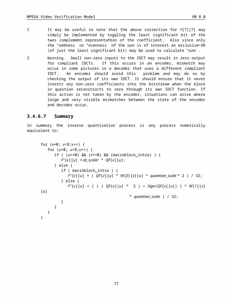
MPEG4 Video Verification Model VM 8.0
Table X.2 Residual Error Conditions utilized in Error Resilient Core Experiments
Case No.
Error Condition
1 Random errors, with BER 10E-2 and 10E-3
2 Burst errors, using a 2 state Markov model. Average BER 10E-2 and 10E-3, BER during error burst 10E-1, average burst length 1 ms and 10 ms.
3 Random packet loss, with packet length 100, 200 or 400 bits, and packet loss rate 10E-2 and 10E-3.
A brief explanation as to the basis for these particular error conditions is as follows. In case 1, the errors are simply being passed on to the video layer by the multiplexer. This might arise in the case of a wireless channel where extensive interleaving is performed by the network. Case 2 is representative of the errors caused by a fading wireless channel, where the multiplex is able to successfully decode its packet headers. Case 3 models the situation where the multiplex is unable to decode a packet header, and hence the whole of the data in a multiplex packet is lost. This case is also representative of packet losses caused by time-outs that might occur in an internet application.
As shown in Figure XX, in addition to the resync marker field the encoder also inserts a field indicating the current macroblock address or number, macroblock_number, a field indicating the current quantization parameter, quant_scale, and a Header Extension Code, HEC. When HEC is set to 1, the VOP_Temporal_Incr, and VOP_modulo_time are included in the resynchronization header. This additional information is provided to the decoder in case the VOP start_code is corrupted. This additional information enables the decoder to determine which VOP a resync packet belongs to.
3.6.2.4.2 Data Partitioning
When the “data_partitioning” flag is set 1, then in addition to the resync_marker fields, macroblock_number, quant_scale and HEC, a motion_marker field is inserted after the motion data (before the beginning of the texture data). This motion_marker field is unique from the motion data and enables the decoder to determine when all the motion information has been received correctly.
3.6.2.4.3 Reversible VLCs
If the Reversible_VLC flag is enabled then the texture data should be encoded using the reversible VLCs provided in Appendix B (please see Section 4.8.2 for additional syntax details). The use of reversible VLCs enables the decoder to recover additional texture information in the presence of errors. This is accomplished by first detecting the error and searching forward to the next resync_marker, once this point is determined the texture data can be read in the reverse direction until an error is detected. When errors are detected in the texture data, the decoder can use the
77
MPEG4 Video Verification Model VM 8.0
correctly decoded motion vector information to perform motion compensation and conceal these errors.
3.6.2.5 Decoder Operation
When an error is detected in the bitstream, the decoder should resynchronize at the next suitable resynchronization point. Where a VOP header is missed or received with obvious errors, this should be the next VOP start code. Otherwise, the next resynchronization point in the bitstream should be used.
Under the following error conditions, the baseline decoder should resynchronize at the next resynchronization point in the bitstream:
1. An illegal VLC is received.
2. More than 64 DCT coefficients are decoded in a single block.
3. Inconsistent resynchronization header information (i.e., QP out of range, MBN(k) < MBN(k-1), etc.)
4. Resynchronization marker is corrupted.
Under the following error conditions, the decoder should resynchronize at the next VOP header:
1. VOP start code corrupted.
For other resynchronization techniques, conditions for error detection and resynchronization should be as close as possible to those outlined above.
Missing blocks should be replaced with the same block from the previous frame.
3.7 Rate ControlRate control and buffer regulation is an important issue for both VBR and CBR applications. In the case of VBR encoding, the rate controller attempts to achieve optimum quality for a given target rate. In the case of CBR encoding and real-time application, the rate control scheme has to satisfy the low-latency and VBV buffer constraints. In addition, the rate control scheme has to be applicable to a wide variety of sequences and bit rates.
The VM scalable rate control (SRC) scheme is designed to meet both VBR without delay constraints and CBR with low-latency and buffer constraints. The VM5.1 SRC scheme is scalable for various bit rates (e.g. 10kbps to 1Mbps), various spatial resolutions (e.g. qcif to cif) and various temporal resolutions(e.g. 7.5fps to 30fps) and various coders (e.g. DCT and wavelet). The technique is based on [MPEG 95/0436, MPEG 96/1109]. VM rate control is for single VO, and extensions to M-VOs and other improvements are being addressed in the Core Experiment Q2. The rate control in [MPEG 95/0436] handles I, P, and B pictures. The current description in this version only contains I and P pictures.
The SRC scheme assumes that the encoder rate distortion function can be modeled as
78
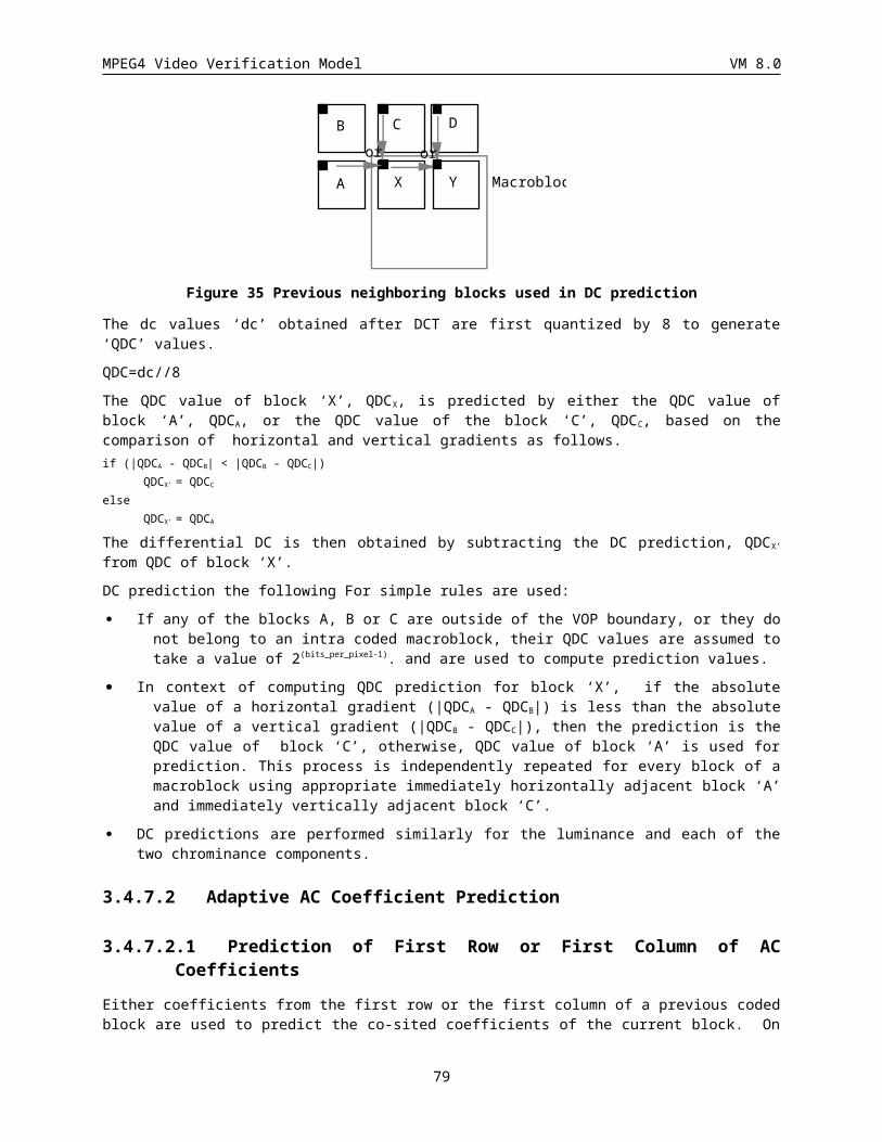
MPEG4 Video Verification Model VM 8.0
R=X1*S*Q**(-1)+X2*S*Q**(-2)
The encoding bit count is denoted as R. The encoding complexity which is sum of absolute difference (SAD) is denoted as S. The quantization parameter is denoted as Q. The modeling parameters are denoted as X1 and X2. Because of the generality of the assumption, the VM scalable rate control scheme is applicable to a variety of bit rates, spatial resolutions, temporal resolutions, buffer constraints and types of coders.
There are four steps in the SRC scheme:
1). Initialization
· X1 and X2 are the first and second order coefficients.
2). Computation of the target bit rate before encoding.
· The target bit rate is computed based on the bits available and the last encoded frame bits. If the last frame is complex and uses excessive bits, more bits should be assigned to this frame. However, there are less bits left for encoding. Thus, less bits can assigned to this frame. A weighted average reflects a compromise of these two factors.
· A lower bound of target rate (R/30) is used so that minimal quality is guaranteed.
· The target rate is adjusted according to the buffer status to prevent both overflow and underflow.
3). Computation of the quantization parameters(QP) before encoding.
· QP is solved based on the model parameters X1 and X2.
· QP is clipped between 1 and 31.
· QP is limited to vary within 25 percent of the previous QP to maintain a VBR quality.
4). After encoding model parameters is updated based on the encoding results of the current frame.
· The rate distortion model is updated based on the encoding results of the current frame. The bits used for the header and the motion vectors are deducted since they are not related to QP.
· The data points are selected using a window whose size depends on the change in complexity. If the complexity changes significantly, a smaller window with more recent data points is used.
· The model is calibrated again by rejecting the outlier data points. The rejection criteria is that data point is discarded when the prediction error is more than one standard deviation.
· The next frame is skipped if the current buffer status is above 80 percents.
The algorithm is described as follows:
Step 1: Initialization after the first frame is coded
Rs: bit rate for the sequence (or segment). /* e.g., 24000 bits/sec */
Rf: bits used for the first frame. /* e.g., 10000 bits */
Rc: bits used for the current frame. It is the bit count obtained after encoding.
Rp: bits to be removed from the buffer per picture.
Ts: number of seconds for the sequence (or segment). /* e.g., 10 sec */
Ec: mean absolute difference for the current frame aftern motion compensation.
Qc: quantization level used for the current frame.
Nr: number of P frames remaining for encoding.
Ns: distance between encoded frames. /* e.g., 4 for 7.5 fps */
Rr: number of bits remaining for encoding this sequence (or segment).
T: target bit to be used for the current frame.
79
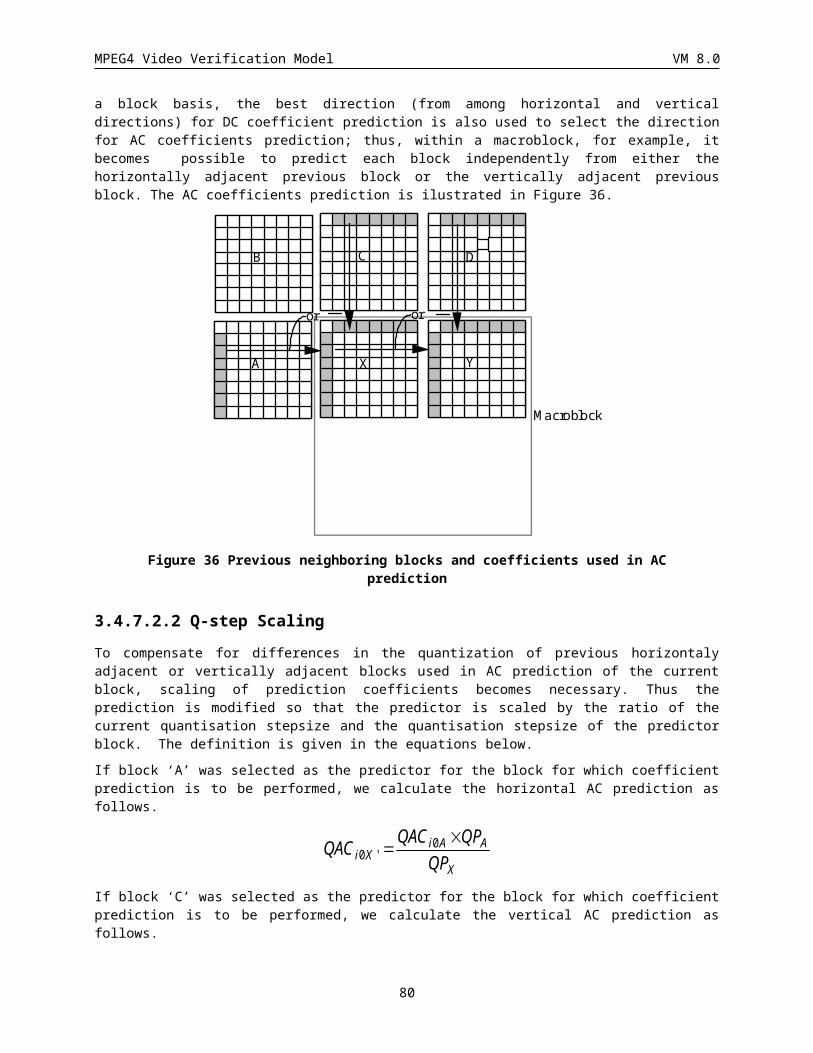
MPEG4 Video Verification Model VM 8.0
S: number of bits used for encoding the previous frame.
Hc: header and motion vector bits used in the current frame.
Hp: header and motion vector bits used in the previous frame.
Ql: quantization level used in the previous frame
Bs; buffer size e.g., R/2
B; current buffer level e.g., R/4 - start from the middle of the buffer
X1 = Rs*Ns/2; /* 1st order coefficient. transient/
X2 = 0; /* 2nd order coefficient */
Rr = Ts*Rs-Rf; /* total number of bits available for this segment */
Rp = Rr/Nr; /* the average bits to be removed from the buffer */
Step 2: Target Bit Calculation (Before Encoding the Current Frame)
T=Max(Rs/30,Rr/Nr*0.95+S*0.05);/*each frame is assigned a minimum of R/30 */
T=T*(B+2*(Bs-B))/(2*B+(Bs-B)); /* increase if less than half */
/* decrease if more than half, don’t change if half */
if (B+T > 0.9*Bs)
T = Max(Rs/30, 0.9*Bs-B); /* to avoid overflow*/
else if (B-Rp+T < 0.1*Bs)
T = Rp-B+0.1*Bs; /* to avoid underflow*/
Step 3: Quantization Level Calculation (Before Encoding the Current Frame)
if (X2==0) Qc = X1*Ec/T; /* fall back 1st order mode */
else Qc= (2*X2*Ec)/(sqrt((X1*Ec)**2+4*X2*Ec*T)-X1*Ec)
/* 2nd order mode */
Qc = Min (ceil(Ql*1.25), Qc, 31); /* clipping*/
Qc = Max (ceil(Ql*0.75), Qc, 1); /* clipping */
Quantization();
Encoding();
Step 4: After encoding the current frame
B += Rc - Rp; /* update buffer fullness */
Rr -= Rc; /* update the remaining bit counts */
S = Rc; /* update the previous bit counts */
Hp = Hc; /* update the previous header and motion bit counts */
Qp = Qc; /* update the previous quantization level */
Nr--; /* update the frame counter */
UpdateRDModel(Qc,Rc,Ec,Hc,X1,X2);
/* estimation of a new model */
if (B > 0.8 * Bs) {
80
MPEG4 Video Verification Model VM 8.0
skip_next_frame();
Nr--;
B -= Rp;
}
If the buffer has reached 80% of the buffer size, the encoder will skip the upcoming frame to be encoded. Thus the buffer is reduced to prevent from the buffer overflow.
UpdateRDModel (Qc, Rc, Ec, Hc, X1, X2) {
Qp[n]: quantization levels for the past frames
Rp[n]: scaled encoding complexity used for the past frames
n: number of encoded past frames;
x: matrix contains Q;
y: matrix contains Q*(R-H)/E;
Ep: mean absolute difference for the previous frame. This is computed after motion compensation for the Y component only. No normalization is necessary since the model is a linear function of Ep.
R[n] = (Rc-Hc)/Ec;
Q[n] = Qc;
n = Min(total_data_number, 20) /* Maximum data number set to 20 */
if(Ep>Ec)
n = (int)(Ec/Ep*20+1); /* sliding window for scene change */
else
n = (int)(Ep/Ec*20+1); /* sliding window for scene change */
Ep = Ec; /* update mad */
Estimator();
RemoveOutlier(X1,X2,Qp,Rp,Ec);
Estimator();
}
Estimator() {
x = [1, Qp[i]**(-1)( i=1,2,...n)] /* Dimension nx2 */
y = [Qp[i]*Rp[i] (i=1,2,.....n)] /* Dimension nx1 */
X1=0;
X2=0;
if (all Qp[i,2] are the same)
for (i=1; i<=n; i++) X1 += y[i]/n;
else {
b = (x_Transpose*x)**(-1)*x_Transpose*y;
/* Dimension of the matrix */
/* 2x1 = (2xn * nx2)**(-1)*(2xn)*(n*1) */
81
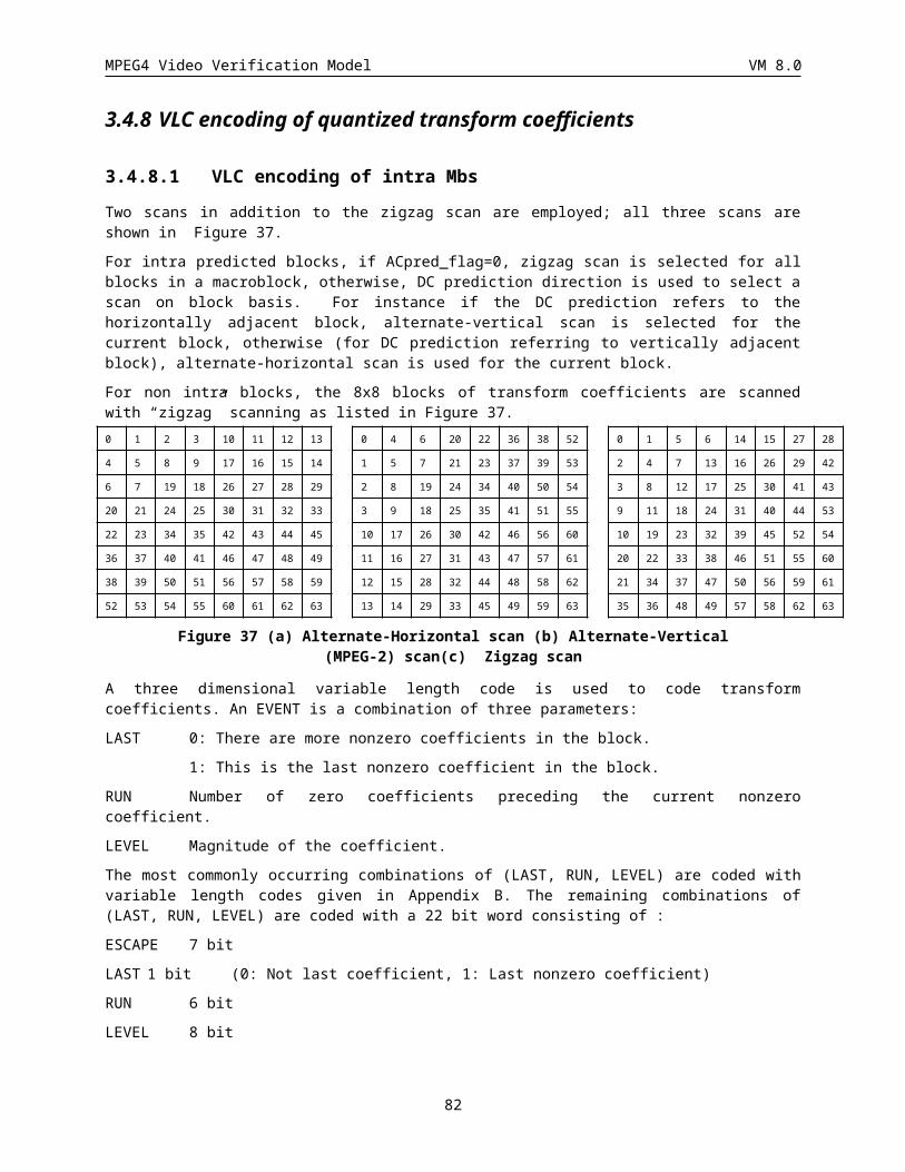
MPEG4 Video Verification Model VM 8.0
X1 = b(1,1);
X2 = b(2,1);
}
}
RemoveOutlier(X1,X2,Qp,Rp,Ec) {
error[n]; Estimation error
for (i=1; i<=n; i++) {
std += ((X1*Ec*Qp[i]**(-1)+X2*Ec*Qp[i]**(-2)-Rp[i]*Ec))**2;error[i] = X1*Ec*Qp[i]**(-1)+X2*Ec*Qp[i]**(-2)-Rp[i]*Ec;
}threshold = sqrt(std/n); /* Setup rejection threshold */for (i=1; i<=n; I++)
if(error[i] > threshold)data point i will not be included for matrix x and y for the estimator.
}
The scalable rate control scheme achieves frame level rate control for both VBR and CBR case. It assumes a simple quadratic rate distortion function of the video encoder. In the case of CBR encoding, a variable frame rate approach is used to achieve the target rate. If a tighter rate control is desired, the same technique is applicable at either slice layer or macroblock layer. Because of the generality of this scheme, extension of such a scheme to shape coding and Multiple-VO coding can be easily made on the basis of the existing VM rate control framework.
3.8 Generalized Scalable EncodingRealizing that many applications require video to be simultaneously available for decoding at a variety of resolutions or qualities this VM supports scalability. In general, scalability of video means the ability to achieve video of more than one resolution and/or quality simultaneously. Scalable video coding involves generating a coded representation (bitstream) in a manner which facilitates the derivation of video of more than one resolution and/or quality by scalable decoding. Bitstream Scalability is the property of a bitstream that allows decoding of appropriate subsets of a bitstream to generate complete pictures of resolution and/or quality commensurate with the proportion of the bitstream decoded. If a bitstream is truly scalable, decoders of different complexities, from low performance decoders to high performance decoders can coexist, and while low performance decoders may decode only small portions of the bitstream producing basic quality, high performance decoders may decode much more and produce significantly higher quality.
Two main types of scalability are: the spatial scalability, and the temporal scalability. The spatial scalability offers scalability of the spatial resolution, and the temporal scalability offers scalability of the temporal resolution. Each type of scalability involves more than one layers. In the case of two layers consisting of a lower layer and a higher layer; the lower layer is referred to as the base-layer and the higher layer is called the enhancement-layer. Traditionally, these scalabilities are applied to frames of video such that in case of spatial scalability, the enhancement-layer frames enhances the spatial resolution of base-layer frames, while in temporal scalability, the enhancement-layer frames are temporally multiplexed with the base-layer frames to provide a higher temporal resolution video. Many MPEG-4 applications are however even more demanding and necessitate not only traditional frame based scalabilities but also scalabilities of VOPs of arbitrary shapes.
The scalability framework discussed in this VM is referred to as generalized scalability and includes the spatial and the temporal scalabilities. In the case of temporal scalability, this VM supports both frames (rectangular
82
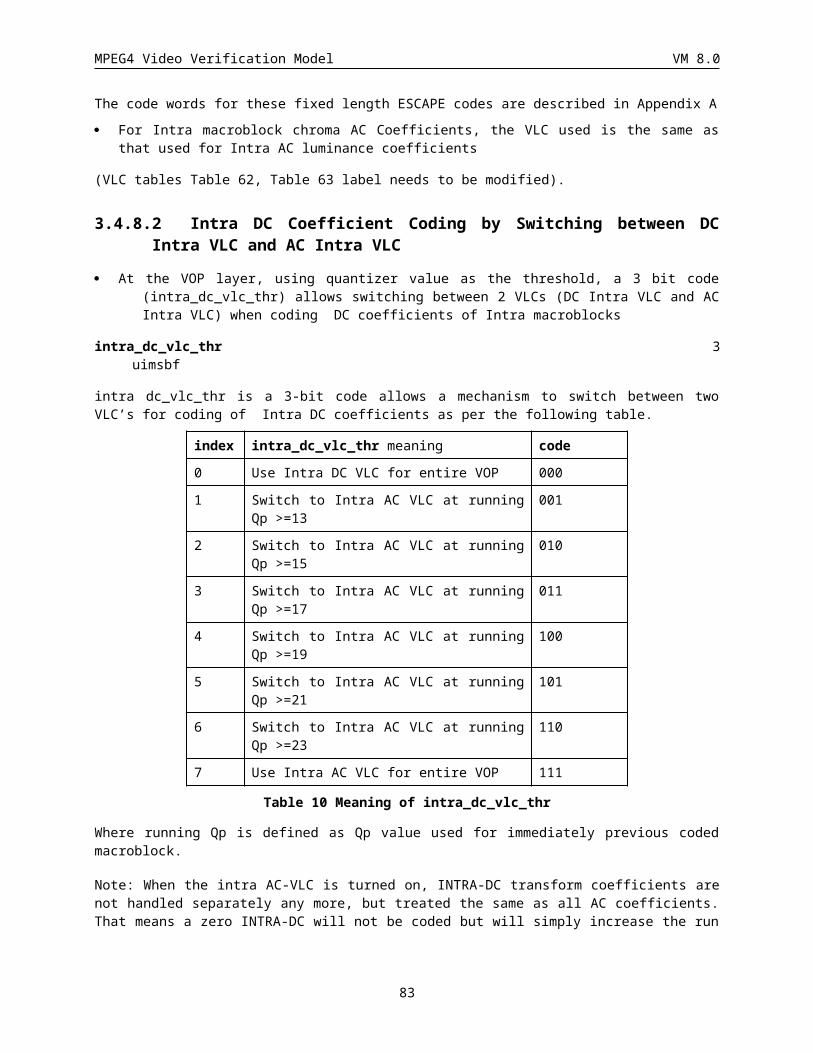
MPEG4 Video Verification Model VM 8.0
VOPs) as well as arbitrary shaped VOPs, however, in the case of spatial scalability, only rectangular VOPs are presently supported. Figure 40 shows a high level codec structure for generalized scalability.
MSD
L Mu
x
Base Layer
MPEG-4in_ 1
in_ 0
inPreProcessor MS
DL D
emux
Decoder
Layer1 Decoder
out_ 0
PostProcessor
outp_ 1
out_ 1
outp_ 0
MPEG-4
Enhancement
MPEG-4
MidProcesssor1
MPEG-4Enhancement
Scalability
Encoder
Layer1 Encoder
Base Layer
MidProcesssor1Scalability
Figure 40: A High Level Codec Structure for Generalized Scalability.
Video VOPs (rectangular or otherwise) are input to Scalability PreProcessor and if spatial scalablity is to be performed with base layer at lower spatial resolution and the enhancement layer at higher spatial resolution, this preprocessor performs spatial downsampling of input VOPs to generate in_0 which forms the input to MPEG-4 Base Layer Encoder which performs nonscalable encoding. The reconstructed VOPs from base layer are then fed to Midprocessor1 which in this case performs spatial upsampling. The other output of PreProcessor corresponds to the higher spatial layer VOPs and forms the input (in_1) to the MPEG-4 Enhancement Layer Encoder. The base- and enhancement-layer bistreams are multiplexed by MSDL Mux and either stored or transmitted and by employing an MSDL Demux can be retrieved for decoding by corresponding MPEG-4 Base Layer Decoder and MPEG-4 Enhancement Layer Decoder. The operation of Midprocessor1 is identical to that at the encoder. The Scalability PostProcessor performs any necessary operations such as spatial upsampling of the decoded base layer for display resulting at outp_0 while the enhancement layer without upsampling may be output as outp_1.
When the generalized codec is used to perform temporal scalability, the Scalability PreProcessor performs temporal demultiplexing of a VO into two substreams of VOPs, one of which (in_0) is input to the MPEG-4 Base Layer Encoder and the other (in_2) is input to the MPEG-4 Enhancement Layer Encoder. In this case, Midprocessor1 does not peform any spatial resolution conversion and simply allows the decoded base-layer VOPs to pass through and these VOPs are used for temporal prediction in encoding of enhancement-layer. The operation of MSDL Mux and MSDL Demux is exactly similar as in case of spatial scalability. The decoding of base and enhancement-layer bitstreams occurs in the corresponding base- and enhancement-layer decoders as shown. The PostProcessor simply outputs the base layer VOPs without any conversion, but temporally multiplexes the base and enhancement layer VOPs to produce higher temporal resolution enhancement layer.
As mentioned earlier, since VOPs can have a rectangular shape (frame) or an irregular shape, both the traditional spatial and temporal scalabilities as well as object based spatial and temporal scalabilities become possible. In this current version of the VM, spatial scalability is limited to rectangular VOPs. We now describe the encoding process for the spatial and temporal scalabilities.
3.8.1 Spatial Scalability Encoding
3.8.1.1 Base Layer and Enhancement LayersAs mentione earlier, in spatial scalability, the base layer and the enhancement layer can have different spatial resolution. In this VM, the base layer has lower resolution and the enhancement layer has higher resolution. For example, in simulations, the base-layer uses QCIF resolution and the enhancement-layer uses CIF resolution.
83
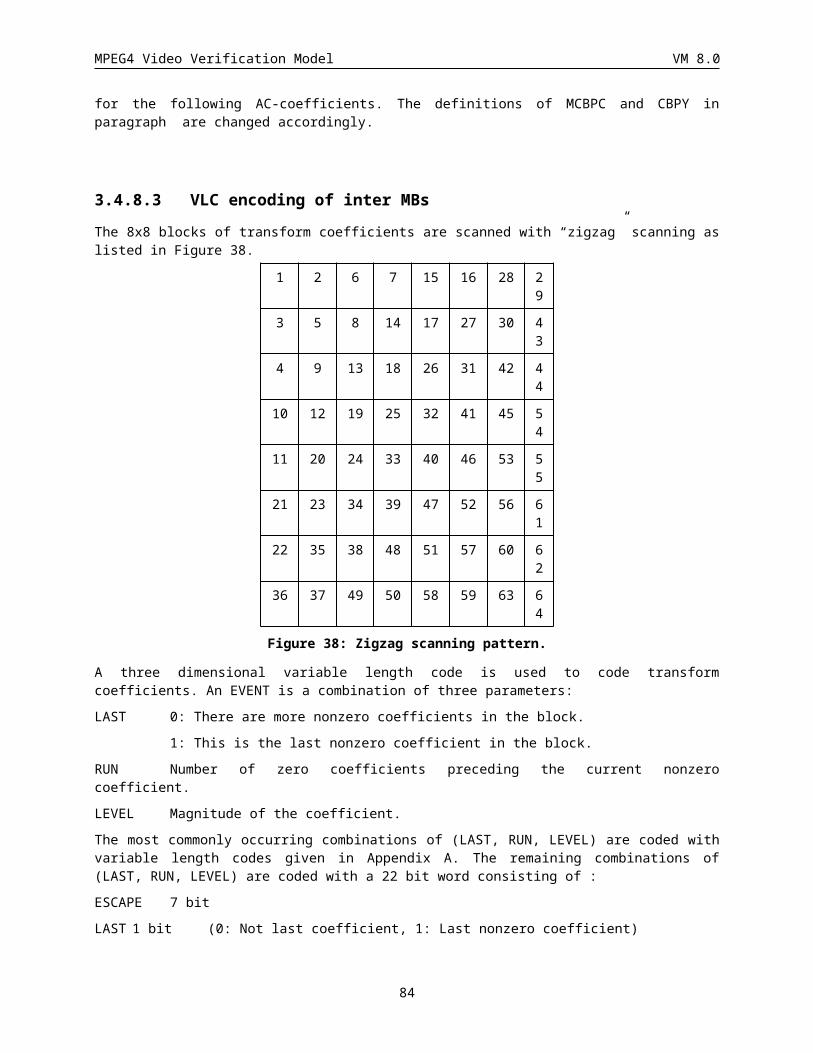
MPEG4 Video Verification Model VM 8.0
3.8.1.2 DownsamplingThe downsampling process is performed at the scalability preprocessor. For example, the downsampling process from ITU-R 601 to CIF/QCIF is described in Section Filtering process. The downsampling process for the factor of 2 is only described in this document, however downsampling for arbitary factor is allowed.
3.8.1.3 Encoding of Base LayerThe encoding process of the base layer is the same as non_scalable encoding process.
3.8.1.4 Upsampling ProcessThe upsampling process is performed at the midprocessor. The VOP of the base layer is locally decoded and the decoded VOP is upsampled to the same resolution as that of the enhancement layer. In case of the example above, upsampling is performed by the filtering process described in Figure 41 and Table 12.
CIFQCIF
1
3
3
1
Figure 41
Factor Tap no. Filter taps Divisor
2 1 1, 3 4
2 3, 1 4
Table 12
3.8.1.5 Encoding of Enhancement LayerThe VOP in the enhancement layer is encoded as either P-VOP or B-VOP. The relationship between VOP in the base layer and that of the enhancement layer is illustrated in Figure 42. The VOP which is temporally coincident with I-VOP in the base layer is encoded as P-VOP. The VOP which is temporally coincident with P-VOP in the base layer is encoded as B-VOP. In case of the spatial scalability, a decoded VOP in the base layer is used as a reference of the prediction. The temporally coincident VOP in the reference layer (base layer) must be coded before the encoding of the VOP in the enhancement layer.
84
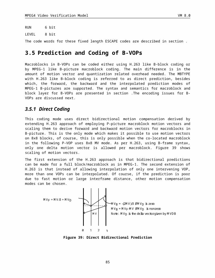
MPEG4 Video Verification Model VM 8.0
I P P
P B B
Figure 42
3.8.1.6 Encoding of P-VOPs of Enhancement LayerIn P-VOP, the ref_select_code is set to “11”, i.e., the prediction reference is set to I-VOP which is temporally coincident VOP in the base layer.
In P-VOP, the motion vector is always set to 0, thus motion vector is not encoded to reduce the overhead.
Mode decisions in P-VOP
In case of P-VOP, the encoder makes a decision on whether to use INTRA or INTER prediction in the coding. The method to decide the mode is the same as INTRA/INTER mode decision in the coding of the base layer. (See section ) If INTER mode is chosen, the macroblock is coded using the prediction from the VOP in the base layer. The INTER4V mode is not used in the coding of the enhancement layer.
3.8.1.7 Encoding of B-VOPs of Enhancement LayerIn B_VOP, the ref_select_code is set to “00”, i.e., the backward prediction reference is set to P-VOP which is temporally coincident VOP in the base layer, and the forward prediction reference is set to P-VOP or B-VOP which is the most recent decoded VOP of the enhancement layer.
In B-VOP, when the backward prediction is selected, i.e., the prediction from the base layer is selected, the motion vector is always set to 0, thus thus motion vector is not encoded to reduce the overhead.
Mode decision for B-VOP
In case of the spatial scalability, the Direct (H.263 B) mode is not used. A macroblock in B-VOPs is coded in one of the other three modes. The encoder makes a decision on which mode is the best. SAD (sum of absolute differences) is calculated for each of the three modes. The MBTYPE mode is selected as follows,
if (SADforward <= min{SADinterpolate, SADbackward, SADforward} ) forward mode
else if (SADinterpolate <= min{SADinterpolate, SADbackward, SADforward} ) interpolate mode
elsebackward mode
3.8.2 Temporal Scalability EncodingIn Object-based Temporal scalability (OTS), the frame rate of a selected object is enhanced such that it has a smoother motion than the remaining area. In other words, the frame rate of the selected object is higher than that of the remaining area. There are two types of enhancement structures in OTS.
Figure 43 shows the example of Type 1 where VOL0 (VideoObjectLayer 0) is an entire frame with both an object and a background, while VOL1 represents the particular object in VOL0. VOL0 is coded with a low frame rate and
85
MPEG4 Video Verification Model VM 8.0
VOL1 is coded to achieve a higher frame rate than VOL0. In this example, frames 2 and 4 are formed by combining two base layer frames 0 and 6 followed by overlapping the object of the enhancement layer onto the combined frame. The combined frame is formed using a process we call “background composition”, as described in Section . In this example, forward predictions forming P-VOPs are used. Figure 44 shows another example of Type 1 that also uses bidirectional predictions forming B-VOPs in the enhancement layer. In both cases, two additional shape data, a forward shape and a backward shape, are encoded to perform the background composition. Note that these shapes will not be encoded, when the sequence ends with enhancement layer frames, In this case, backward_shape for the previous VOP is copied to both forward_shape and the backward_shape for the current VOP. For example, if the base layer stops at frame 6 in Figure 43, the forward shape and backward shape for frames 8 and 10 are identical to the backward shape for frames 2 and 4.
Figure 45 shows the example of Type 2 where VO0 (VideoObject 0) is the sequence of an entire frame which only contains a background and it has no scalability layer. VO1 is the sequence of a particular object and it has two scalability layers, VOL0 and VOL1. VOL1 represents the same object as VOL0 and it is coded to achieve a higher frame rate than VOL0. In this example, VOL0 is regarded as a base layer and VOL1 is regarded as an enhancement layer of the OTS. Note that the VO0 may not have the same frame rate as other VOs.
VOL0
frame number
Base Layer
0 6 12
EnhancementLayer
VOL1
frame number0 6 122 4 8 10
Figure 43: Enhancement structure of Type 1 with P-VOPs.
86
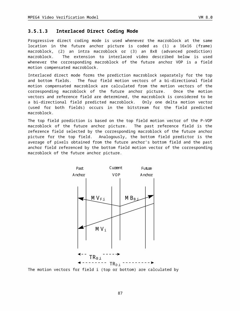
MPEG4 Video Verification Model VM 8.0
VOL0
frame number
Base Layer
0 6 12
EnhancementLayer
VOL1
frame number0 6 122 4 8 10
Figure 44: Enhancement structure of Type 1 with B-VOPs.
VO0
frame number0 66
12
VOL0of VO1
Base Layer
frame number0 6 12
EnhancementLayerVOL1
of VO1
frame number0 6 123 9 15
Figure 45: Enhancement structure of Type 2.
There are 2 types of enhancements for scalability, described by the enhancement_type flag. We explain below the meaning of enhancement_type flag in more detail. As an example, Figure 46 shows an entire image containing several types of regions; for example a road, a car, and mountains. Both the base layer with enhancement_type being “0” and the base layer with enhancement_type being “1” are coded with lower picture quality which means that either the frame rate is lower or the spatial resolution is lower. At the enhancement layer of the scalability, enhancement_type flag distinguishes the following two cases.
87
MPEG4 Video Verification Model VM 8.0
· When this flag is “1”, the enhancement layer increases the picture quality of a partial region of the base layer. For example, in Figure 46, VOL0 is an entire frame and VOL1 is the car in the frame. The temporal resolution or the spatial resolution of the car is enhanced.
· When this flag is “0”, the enhancement layer increases the picture quality of the entire region of the base layer. For example, in Figure 46, if VOL0 represents an entire frame, VOL1 is also the entire frame. Then the temporal or spatial resolution of entire frame is enhanced. If VOL0 represents the car, VOL1 is also the car which is enhanced in terms of temporal or spatial resolution.
Note that since only rectangular VOP-based spatial scalability is included in this current version of the VM, enhancement_type flag is always set to “0” for spatial scalability.
The reference shape data for inter shape coding in an enhancement layer does not exist when the base layer is the reference and it is coded with video_object_layer_shape being “00.” In this case, the reference shape for the current shape coding is defined as a binary rectangle of the size of the entire image.
VOL1 : carVOL0 : entire frame
VOL0 : car
VOL0 : entire frame
enhancement_type = 1
: region to be enhanced by an enhancement layer
Base layer Enhancement layer
enhancement_type = 0
VOL1 : entire frame
VOL1 : car
Figure 46: Example of a region to be enhanced.
Editor’s note: All scalability modes can be applied in the case of extension to 8-bit video. It is not necessary that enhancement and base layers are specified as having the same number of bits per pixel.
88
MPEG4 Video Verification Model VM 8.0
3.9 Sprite Coding and Global Motion Compensation
3.9.1 IntroductionA sprite is an image composed of pixels belonging to a video object visible throughout a video segment. For instance, sprite generated from a panning sequence will contain all the visible pixels of the background object throughout the sequence. Portions of this background may not be visible in certain frames due to the occlusion of the foreground objects or the camera motion. Since the sprite contains all parts of the background that were at least visible once, the sprite can be used for direct reconstruction of the background VOP’s or the predictive coding of the background VOP’s. Sprites for background are commonly referred to as “background mosaics” in the literature.
The sprite encoding syntax can be utilized for the transmission of any still image to the decoder since a sprite is essentially just a still image. The syntax also will allow for the transmission of a still image as a sprite progressively, both spatially, where the sprite is reconstructed at the decoder a piece at a time, and hierarchically, where the image quality is updated with residual images.
In sprite-based coding, we distinguish two main types of sprites: (1) off-line static sprites, and (2) on-line dynamic sprites. Static sprites are those that are directly copied (including appropriate warping and cropping) to generate a particular rendition of the sprite at a particular time instant, namely a VOP. In contrast, a dynamic sprite is used as reference in predictive coding where motion is compensated using the warping parameters for the sprite. A static sprite is built off-line, and is coded and transmitted as an I-VOP prior to coding the video itself. A dynamic sprite is dynamically built on-line during coding in both the encoder and the decoder.
Off-line On-line
Static Built prior to coding
No predictive coding
----
Dynamic ---- Built during coding
Predictive coding
The current VM allows two kinds of sprite coding, namely, off-line static sprite (see sections and ) and on-line dynamic sprite (see sections and ).
Off-line static sprites are particularly suitable for synthetic objects. They are also suitable for natural video objects that mostly undergo rigid motion when a wallpaper-like rendering is appropriate. On-line dynamic sprites provide with an enhanced predictive coding environment. In the case of natural video objects, on-line dynamic sprites should be preferred when a no-latency solution is needed, or when details induced by local motion should be preserved.
One of the major components of sprite-based coding is the generation of the sprite unless it is known a priori such as may be the case for a synthetic VO. The sprite is built in a similar way in both off-line and on-line cases as the same global motion estimation algorithm is used. In the off-line case, the sprite is built before starting the encoding process using the original VOPs. In the on-line case, both the encoder and the decoder build the same sprite from reconstructed VOPs. In sprite coding, the chroma components are processed in the same way as the luminance component, with the properly scaled parameters.
Scalability and B-VOPs are currently not supported for on-line dynamic sprites. For off-line static sprites, temporal scalability is implicit since the transmission of trajectories of each VOP is independent. In addition, the flexibility to transmit the sprite piece by piece as required by the timing considerations and bandwidth constraints as well as to transmit a lower quality version of the sprite initially and improve it over time with residual images provides another dimension of scalability the use static sprites.
A main component of sprite generation is the estimation of relative global motion between the previous and current VOPs (on-line dynamic sprite) or between the sprite and the current VOP (off-line static sprite). Global motion is modeled on the basis of a parametric geometrical model, such as the perspective transform. The current
89
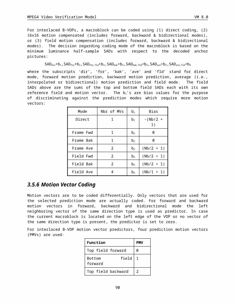
MPEG4 Video Verification Model VM 8.0
VM allows a number of transformations to be used with sprite: stationary, translation, isotropic magnification rotation and translation, affine, and perspective. Each transformation can be defined as either a set of coefficients or the motion trajectories of some reference points. While the former representation is convenient for performing the transformation, the latter is necessary for encoding the transformations. The number of reference points needed to encode the warping parameters determines the transform to be used for warping, this number is defined by no_of_sprite_points in the Video Object Layer.
If the number of reference points equals to four, a perspective transformation is to be used for warping. In this case, the transform is defined by
x’ = (a x + b y + c)/(g x + h y + 1)
y’ = (d x + e y + f)/(g x + h y + 1),
where {a, b, c, d, e, f, g, h} are the coefficients of the transformation, (x, y) is the coordinate in the current VOP, and (x’, y’) is the coordinate in the previous VOP expressed in the VOP coordinate system , in case of on-line dynamic sprite, or (x’, y’) is the coordinate in the sprite expressed in the sprite coordinate system, in the case of off-line static sprite.
Cases with zero to three reference points 0 to 3 are treated as special cases of the perspective transform. In the following, we discuss some details of each case using the forward transform as an example.
· 0 point: This case is used for stationary VOs. No trajectory point is needed (encoded) for warping if the VO is stationary. In this case, a = e = 1 and b = c = d = f = g = h = 0, i.e., x’ = x and y’ = y.
· 1 point: This is the warping model of choice for VOs undergoing mostly translational motion. Only one point is needed, and thus encoded, if the motion of the VO is translational. In this case, we have a = l = e =1, b = g = h =d = 0 and the transform equations look like
x’ = x+ c,
y’ = y + f.
At the decoder, one pair of points (one at sprite and one at a VOP) are enough to solve c and f.
· 2 points: We use this case to represent isotropic magnification, rotation, and translation motion. In this case, g = h = 0. Generally speaking, there are several interpretations of motion specified by two pairs of points. The interpretation taken here, namely, isotropic magnification, rotation, and translation, is a more common, thus more useful one. The transformation equations look like:
x’ = a cosq x + a sinq y + c,
y’ = -a sinq x + a cosq y + f.
It can be simplified to
x’ = a x + b y + c,
y’ = -b x + a y + f,
where a = a cosq and b = a sinq. Since there are four unknowns, given two pairs of points (two at sprite and two at a VOP), the decoder can solve the transformation coefficients in these two equations and perform the warping.
· 3 points: affine transform. Three points are needed (encoded) to represent (at the encoder) an affine transform, and solve (at the decoder) for coefficients {a, b, c, d, e, f}.
x’ = a x + b y + c,
y’ = d x + e y + f.
· 4 points: perspective transform. Four points are needed (encoded) to represent (at the encoder) a perspective transform, and solve (at the decoder) for coefficients {a, b, c, d, e, f, g, h, l}
x’ = (a x + b y + c)/(g x + h y + 1),
y’ = (d x + e y + f)/(g x + h y + 1).
90
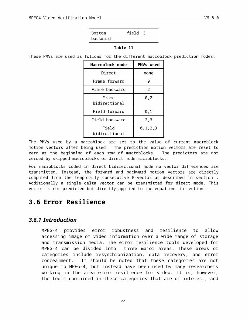
MPEG4 Video Verification Model VM 8.0
3.9.2 Location of Reference PointsIn the following description, it is assumed that luminance pixels exist on an integer-pixel grid and chrominance pixels are located as defined in Figure 2. The coordinate of the left top luminance pixel in the current VOP is defined as follows:
· Rectangular VOP: (0, 0).
· Arbitrary shaped VOP : (VOP_horizontal_mc_spatial_ref, VOP_vertical_mc_spatial_ref),
as specified in the VOP Class.
In the case of sprite coding mode (video_object_layer_sprite_usage == “01” or “10”), the coordinate of the left top luminance pixel in a sprite is (sprite_Left_Edge, sprite_Top_Edge) as specified in the VOL header (see Error: Reference source not found). In the GMC mode (video_object_layer_sprite_usage == “11”), the coordinate of the left top luminance pixel in the reference VOP is defined as follows:
· Rectangular VOP: (0, 0).
· Arbitrary shaped VOP : (VOP_horizontal_mc_spatial_ref, VOP_vertical_mc_spatial_ref),
as specified in the VOP Class of the reference VOP.
A two dimensional index is assigned for each pixel or an interpolated pixel in a VOP or a sprite. The relation between the coordinates and the index in the current VOP is defined as:
· Luminance pixel in the current VOP
x = i,
y = j,
· Chrominance pixel in the current VOP
x = 2 ic + 0.5,
y = 2 jc + 0.5,
where index values i, j, ic,, and jc are integers. The accuracy of the motion vectors for each pixel in the current VOP is defined by warping_accuracy in the Video Object Layer Class. Assuming that 1¸ s pel accuracy (possible values for s are 2, 4, 8, or 16) is adopted for the motion vectors, the relation between the index values and the coordinates in a sprite or a reference VOP is defined as:
· Luminance pixel in a sprite or a reference VOP
x’ = i’ ¸ s,
y’ = j’ ¸ s,
· Chrominance pixel in a sprite or a reference VOP
x’ = 2 ic’ ¸ s + 0.5
y’ = 2 jc’ ¸ s + 0.5
where index values i’, j’, ic’, and jc’ are integers. The interpolated sample values for points with fractional coordinate values are obtained using the interpolation method described in section .
As described above, the transform between sprites and VOPs or between two consecutive VOPs are parameterized using the motion of reference points. shows the location of sprite points (i.e. reference points in a sprite or a reference VOP) and reference points. The definition of the parameters used in this figure is as follows:
(xr(n), y r(n)):coordinates of the rth reference point in the current nth VOP,
(xr’(n), yr’(n)): coordinates of the rth sprite point in the sprite or the rth reference point in the reference VOP,
W(n), H(n): width and height of the bounding box in the nth VOP.
91
MPEG4 Video Verification Model VM 8.0
xr(n) and y r(n) are integers, while xr’(n) and yr’(n) are up to half-pel accuracy (i.e. 0.5 multiplied by an integer). This is because the location of sprite points is specified in half pel accuracy. Integers W(n) and H(n) denote the width and height of a bouding box, which is defined for each VOP. The decoder performs warping only for the pixels included in this bounding box. The area included in the bounding box is defined as pixels located at ( x, y) such that x0(n) x < x0(n) +W(n) and y0(n) y < y0(n) +H(n).
The reference points in a VOP is located at the corners of the bounding box. When m reference points are necessary to define the transform, sprite points located at (xr’(n), yr’(n)) (0 r < m) and reference points located at (xr (n), yr (n)) (0 r < m) are used. The location of these reference points are defined as:
(x1(n), y1(n)) = (x0(n)+W(n), y0(n)),
(x2(n), y2(n)) = (x0(n), y0(n) + H(n)),
(x3(n), y3(n)) = (x0(n)+W(n), y0(n)+H(n)).
In order to determine the transform of the warping, the location of the sprite points, and the location and size (i.e. width and height) of the bounding box are needed to be specified for each VOP. The location (relative to the display window) and size (i.e. W(n) and H(n) in the above equations) of the bounding box are explicitly transmitted using VOP_horizontal_mc_spatial_ref, VOP_vertical_mc_spatial_ref, VOP_width, and VOP_height, at the Video Object Plane Class in the case when arbitrarily shaped VOs are coded. In the case of rectangular VOs, the size of the bounding box (i.e. W(n) and H(n) in the above equations) is determined by video_object_layer_width and video_object_layer_height in the Video Object Layer Class.
sprite or reference VOP
current (nth) VOP
bounding box
reference point
sprite point
(x2(n), y2(n))
(x0(n), y0(n)) (x1(n), y1(n))
(x3(n), y3(n))
(x1’(n), y1’(n))
(x2’(n), y2’(n))
(x0’(n), y0’(n))
(x3’(n), y3’(n))
Figure 47: Sprite points, reference points, and bounding box.
In addition, the sprite points (xr’(n), yr’(n)) can be located outside the sprite or the reference VOP. In the case, the sample values of the edge pixels are used for obtaining the (interpolated) pixel values outside the sprite or the reference VOP as in the unrestricted motion vector mode.
3.9.3 Definition of Transform FunctionsThe transform functions define the relation of index values between the pixels in the current VOP and the corresponding pixels in the sprite. In this section, the following notations are used to simplify the description of transform functions:
I = i - x0(n),
J = j - y0(n),
92
MPEG4 Video Verification Model VM 8.0
Ic = 4 ic - 2 x0(n) + 1,
Jc = 4 jc - 2 y0(n) + 1,
W = W(n),
H = H(n),
ir’ = s xr’(n),
jr’ = s yr’(n),
where Ic, Jc, W, H, ir’ and jr’ are integers. Using the notations provided above, the transform functions for VOP synthesis and dynamic sprite updating (see section Error: Reference source not found) are defined as follows:
I) Stationary transform
VOP synthesis and dynamic sprite update:
i’ = s i
j’ = s j
ic’ = s ic
jc’ = s jc
II) Translational transform
VOP synthesis:
i’ = i0’ + s i,
j’ = j0’ + s j,
ic’ = s ic + i0’ //// 2,
jc’ = s jc + j0’ //// 2,
where the operator “////” indicates integer division which rounds fractional values to the nearest integer, and rounds half integer values towards the positive infinity.
Dynamic sprite update:
i’ = (i + i0’ //// s) s,
j’ = (j + j0’ //// s) s,
ic’ = (ic + i0’ //// (2s)) s,
jc’ = ( jc + j0’ //// (2s)) s.
III) Isotropic transform
VOP synthesis:
i’ = i0’ + ((-i0’ + i1’) I + (j0’ - j1’) J) //// W ,
j’ = j0’ + (-(j0’ - j1’) I +(-i0’ + i1’) J) //// W,
ic’ = ((-i0’ + i1 ’) Ic + (j0’ - j1’) Jc + 2 W i0’ - W s ) //// (4 W) ,
jc’ = (-(j0’ - j1’) Ic +(-i0’ + i1’) Jc + 2 W j0’ - W s) //// (4 W).
Dynamic sprite update:
i’ = ((W i0’ + (-i0’ + i1’) I + (j0’ - j1’) J) //// (W s)) s ,
j’ = ((W j0’ - (j0’ - j1’) I +(-i0’ + i1’) J) //// (W s)) s,
ic’ = (((-i0’ + i1 ‘) Ic + (j0’ - j1’) Jc + 2 W i0’ - W s ) //// (4 W s)) s,
jc’ = ((-(j0’ - j1’) Ic +(-i0’ + i1’) Jc + 2 W j0’ - W s) //// (4 W s)) s.
93
MPEG4 Video Verification Model VM 8.0
IV) Affine transform
VOP synthesis:
i’ = i0’ + ((-i0’ + i1’) H I + (-i0’+ i2’)W J) //// (WH),
j’ = j0’ + (-(j0’ - j1’) H I + (-j0’+ j2’)W J) //// (W H),
ic’ = ((-i0’ + i1’) H Ic + (-i0’+ i2’)W Jc + 2 W H i0’ - W H s) //// (4 W H),
jc’ = (-(j0’ - j1’) H Ic + (-j0’+ j2’)W Jc + 2 W H j0’ - W H s) //// (4 W H).
Dynamic sprite update:
i’ = ((W H i0’ + (-i0’ + i1’) H I + (-i0’+ i2’)W J) //// (W H s)) s,
j’ = ((W H j0’ - (j0’ - j1’) H I + (-j0’+ j2’)W J) //// (W H s)) s,
ic’ = (((-i0’ + i1’) H Ic + (-i0’+ i2’)W Jc + 2 W H i0’ - W H s) //// (4 W Hs)) s,
jc’ = ((-(j0’ - j1’) H Ic + (-j0’+ j2’)W Jc + 2 W H j0’ - W H s) //// (4 W Hs)) s.
V) Perspective transform
VOP synthesis:
i’ = (a i + b j + c) //// (g i + h j + D W H),
j’ = (d i + e j + f) //// (g i + h j + D W H),
ic’ = (2 a Ic + 2 b Jc + 4 c - (g Ic + h Jc + 2 D W H) s) //// (4 g Ic + 4 h Jc + 8 D W H),
jc’ = (2 d Ic + 2 e Jc + 4 f - (g Ic + h Jc + 2 D W H) s) //// (4 g Ic + 4 h Jc + 8 D W H),
where:
g = ((i0’ -i1’ - i2’ + i3’ ) (j2’ - j3’) - (i2’ - i3’) (j0’ -j1’ - j2’ + j3’)) H ,
h = ((i1’ - i3’) (j0’ - j1’ - j2’ + j3’ ) - (i0’ -i1’ - i2’ + i3’ ) (j1’ - j3’)) W ,
D = (i1’ - i3’) (j2’ - j3’ ) - (i2’ - i3’) (j1’ - j3’),
a = D (i1’ - i0’ ) H + g i1’ ,
b = D (i2’ - i0’ ) W + h i2’,
c = D i0’ W H,
d = D (j1’ - j0’ ) H + g j1’,
e = D (j2’ - j0’ ) W + h j2’,
f = D j0’ W H.
Dynamic sprite update:
i’ = ((a i + b j + c) //// ((g i + h j + D W H)s)) s,
j’ = ((d i + e j + f) //// ((g i + h j + D W H)s)) s,
ic’ = ((2 a Ic + 2 b Jc + 4 c - (g Ic + h Jc + 2 D W H) s) //// ((4 g Ic + 4 h Jc + 8 D W H)s)) s,
jc’ = ((2 d Ic + 2 e Jc + 4 f - (g Ic + h Jc + 2 D W H) s) //// ((4 g Ic + 4 h Jc + 8 D W H)s)) s,
The implementor should be aware that a 32bit register may not be sufficient for representing the denominator or the numerator in the above transform functions. The usage of a 64 bit floating point representation should be sufficient in such case.
94
MPEG4 Video Verification Model VM 8.0
3.9.4 Sprite Generation
3.9.4.1 Off-line Sprite GenerationWhen a sprite is generated off-line, the entire video object is assumed to be available. For each VOP in the sequence, the global motion field is estimated according to one of the aforementioned transformation models, using which the VOP then is registered with the sprite by warping the VOP to the sprite coordinate system. In Annex D, the step-by-step instructions for off-line sprite generation, including the procedure for global motion estimation, are provided.
3.9.4.2 On-line Sprite GenerationIn on-line sprite coding, the current frame is always chosen as the reference for increased coding efficiency. Global motion estimation is performed between consecutive VOPs. Using the global warping parameters, the sprite at the previous time instant is aligned with respect to the current VOP and the current VOP is then blended onto the sprite to form the current sprite, as depicted in Figure 48 .
VOPs
Sprites
copy blend blend
warp warp
Global ME Global ME
Figure 48: Sprite generation for on-line dynamic sprites.
3.9.4.2.1 Initialization The size of the buffer to hold the sprite is specified by the two parameters sprite_hdim and sprite_vdim transmitted in the Video Object Layer. Typically, the size of the sprite is larger than the size of the VO.
The sprite is initialized by copying the content of the first VOP to the buffer location specified by sprite_Left_Edge and sprite_Top_Edge in the Video Object Layer. Using these parameters, the origin of the coordinate system for the sprite is moved by (-sprite_Left_Edge, -sprite_Top_Edge) from the upper left corner of the sprite. This implies that the coordinate of the upper left corner of the sprite is (sprite_Left_Edge,
sprite_Top_Edge).The relationship between the spatial location r of a pixel in the VOP and the spatial location
R
in the sprite, therefore, is described as:R =
r .
95
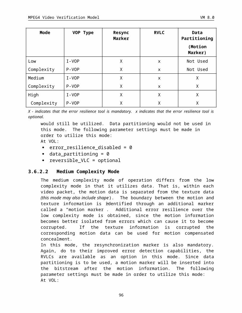
MPEG4 Video Verification Model VM 8.0
Sprite_vdim
Sprite_hdim
VOP_width
VOP_height
(sprite_Left_Edge,sprite_Top_Edge)
(0, 0)
Figure 49: Relative size and position of the sprite and the VOP (in this case, sprite_Left_Edge and sprite_Top_Edge both have negative values).
The placement of the VOP in the sprite will define the trajectories to be encoded as defined in section .
A binary mask of size sprite_hdim x sprite_vdim is associated with the sprite to record pixel locations where sprite content has been observed or updated. Consequently, at initialization time, this implicit sprite shape buffer corresponds to the shape of the first VOP.
Therefore, the initialization of the sprite can be summarized by the following steps:
1. init the sprite (Y and binary mask A) with 0,
2. for each pixel location in the VOP:
- copy the VOP pixel in the sprite
- set the corresponding sprite binary mask location to 255.
In pseudo C code:pel_sprite=0;for (j=0; j<sprite_vdim; j++)
for (i=0; i<sprite_hdim; i++) {spriteY[pel_sprite] = 0;spriteA[pel_sprite] = 0;pel_sprite++;
}for (j=0; j<vop_height; j++)
for (i=0; i<vop_width; i++) {pel_vop = j * vop_width + i;if (vopA[pel_vop]) {
/* the pixel belongs to vop */pel_sprite = (j+offsety) * sprite_hdim + (i+offsetx);spriteY[pel_sprite] = vopY[pel_vop];spriteA[pel_sprite] = 255;
}}
The chroma components of the sprite are initialized in a similar way, except the chrominance sprite dimensions are half that of the luminance sprite and initialization value is 128.
96
MPEG4 Video Verification Model VM 8.0
3.9.4.2.2 Updating of spritesIn the on-line sprite mode, the sprite is updated for each input VOP by being warped using the estimated motion parameters between two consecutive VOPs. The warping of the sprite is performed as described in section , except that the location of the warped pixels is rounded to the nearest neighbor (the transform functions for sprite updating is defined in section ). This process is illustrated in Figure 50.
spritewarped sprite
backwardtransform
scanningthis image
finding warpedpixel value inthis image
Figure 50: Updating of the sprite in the dynamic sprite mode.
Therefore, the warping of the sprite can be summarized by the following steps:
1. scan the sprite,
2. find the warped coordinates using the transform function
3. round the last value to find the warped pixel value
3.9.4.2.3 Blending of the VOP and the spriteThe sprite is continuously updated and build by blending new VOPs onto the sprite one at a time. Once the sprite at the previous time instant has been aligned with respect to the current VOP, the current VOP is blended with the sprite. In the on-line dynamic sprite case, the reconstructed VOP is used.
The blending process is as follows. The sprite is first updated with the warped sprite. Then for those pixel locations where the VOP exists, the sprite is updated either as a weighted sum of the warped sprite and the current VOP if the sprite exists at this location or otherwise by copying the VOP pixel value.
Therefore, the update of the sprite can be summarized by the following steps:
1. the sprite is updated with the warped sprite,
2. for each pixel location in the VOP
- set the binary mask of the sprite to 255
if the warped sprite exists at this location
- the new sprite value is a blending of the warped sprite and the current VOP
else
- the new sprite value is a copy of the current VOP
97
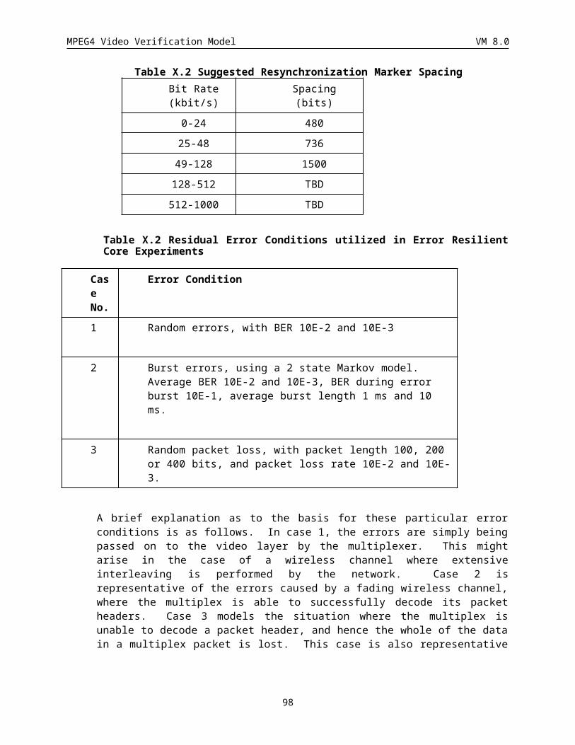
MPEG4 Video Verification Model VM 8.0
The blending_factor controls the update of the sprite and can be dynamically adapted at the VOP level. Its value is in the interval [0,1] and is transmitted in the Video Object Plane.
In pseudo C-code, it gives:pel_sprite=0;for (j=0; j<sprite_vdim; j++)
for (i=0; i<sprite_hdim; i++) {spriteY[pel_sprite] = warp_spriteY[pel_sprite];spriteA[pel_sprite] = warp_spriteA[pel_sprite];/* coordinates in VOP */ii = i - offsetx;jj = j - offsety;pel_vop = jj * vop_width + ii;if (vopA[pel_vop]) {
/* the pixel belongs to vop */if (warp_spriteA[pel_sprite] == 255)
spriteY[pel_sprite]=(1-blend_fact)*warp_spriteY[pel_sprite]+blend_fact* vopY[pel_vop];
/* blending between warped sprite and current vop */else
spriteY[pel_sprite] = vopY[pel_vop];/* new area, update sprite with current vop */
spriteA[pel_sprite] = 255;}pel_sprite++;
}
The chroma components are processed similarly.
3.9.5 Encoding
3.9.5.1 Static Sprite CodingThe main idea of static sprite coding technique is to generate the reconstructed VOPs by directly warping the quantized sprite using specified motion parameters. Residual error between the original VOP and the warped sprite is not added to the warped sprite.
3.9.5.1.1 Low Latency Coding of Static SpritesSince sprites consist of the information needed to display multiple frames of a video sequence, they are typically much larger than a single frame of video. Therefore a static sprite can be considered as a large static image. One drawback to sprite technology has been the significant latency incurred when utilizing large sprites. The sprite coding syntax allows large static sprite VOPs to be sent piece by piece as well as hierarchically so that the latency incurred to start displaying a video sequence will be dramatically reduced. This syntax may be utilized to transmit any large images progressively, both spatially and in terms of quality.
One method of reducing the latency to transmit large sprites is to first transmit only the portion of the sprite needed to reconstruct the first few frames and transmit the remaining pieces as dictated by the decoding requirements and bandwidth availability. The second method of reducing latency is to first transmit a low resolution or highly quantized version of the sprite to begin the reconstruction of the sequence and transmit residual images to improve upon the original sprite image quality as bandwidth becomes available. These two methods may be utilized separately or in combination. It is also possible to not utilize these capabilities and transmit the sprite as a single image without adding additional pieces to it or updating its quality.
One functionality of the sprite coding syntax allows the sprite to be transmitted via a piece-meal method. Under this syntax, only the size of the sprite, the location offset of the initial piece of the sprite, the initial piece of the sprite, and the shape information for the entire sprite are transmitted at the Video Object Layer. The transmission
98
MPEG4 Video Verification Model VM 8.0
of the remaining portion of the sprite is moved to the Video Object Plane. At the Video Object Plane, the remaining portions of the sprite are parceled into small pieces for transmission along with the trajectory points. During each frame’s transmission, one or more pieces of the sprite is sent along with size, location, and corresponding trajectory points information. For simplicity, width, height, x offset, and y offset are constrained to be multiples of 16. The transmission continues until all the pieces are sent. It is the duty of the encoder to insure timely delivery of pieces in a way that regions of the sprite are always present at the decoder before they are needed.
Due to timing and bandwidth restrictions, some sprite pieces transmitted with the piece by piece syntax may have been delivered at a lower quality than desired. The second functionality provided by this syntax is designed to improve the quality of any pieces initially transmitted at lower than desired quality. To improve these low quality regions of the transmitted sprite, residuals of these regions are calculated and transmitted as quality update pieces in a way similar to the transmission of sprite pieces. These quality update pieces can be sent in place of or along with sprite pieces at anytime as allowed by the timing and bandwidth constraints. That is, as long as the delivery of the next sprite piece can be delayed, a quality update piece can be sent ahead of it. Also, if the bandwidth allows, both object and update pieces can be sent in the same frame. Therefore, this allows for intermingling of sprite pieces with quality update pieces during transmission. Similar to the manner in which sprite object pieces are transmitted, the residual data to the transmitted sprite is parceled into small pieces and transmitted along with the trajectory data. This continues until the desired quality is achieved. An encoder may utilize this syntax more efficiently by analyzing regions of the sprite to determine if update is necessary (e.g., any region that is not going to be shown for the rest of the sequence can be ignored) so the number of quality update pieces transmitted is reduced.
3.9.5.1.2 Shape and Texture codingSprite shape and texture are treated as an I-VOP and therefore coded using the I-VOP method in VideoObjectLayer class, but while sprite pieces use the quantization of Intra macroblocks, the update pieces use the quantization of Non-intra macroblocks. The shape information for the entire sprite is transmitted in the VOL as part of the I-VOP. No shape information is transmitted as part of the VOP with the remaining sprite pieces and residual image pieces.
3.9.5.1.3 Quantization of transformationAs discussed above, motion information of reference points are used to represent the warping information instead of the transform coefficients.
Specifically, we define a set of reference points (xr(n), yr(n)) in the current VOP to be coded. The corresponding sprite points (xr’(n), yr’(n)) in the sprite or in the reference VOP are computed using the global motion parameters estimated by global motion estimation. The sprite points (xr’(n), yr’(n)) are quantized (//) to half-pel accuracy. The set of reference and sprite points defines the quantized transform described in section . This process is illustrated in Figure 51.
99
MPEG4 Video Verification Model VM 8.0
Sprite and sprite points
VOP and reference points
(x’3,y’3)
(x’1,y’1)
(x’2,y’2)
(x’0,y’0)
(x3,y3)(x2,y2)
(x1,y1)(x0,y0)
Figure 51. Parameterization of the transform.
3.9.5.1.4 Trajectory encodingMotion vectors of reference points located at (x0(n), y0(n)), (x1(n), y1(n)), (x2(n), y2(n)), and (x3(n), y3(n)) which are the corner positions of the bounding rectangle, are transmitted as the global motion parameters for each VOP. These are in half pel precision while the actual translation values are retrieved by dividing the decoded value by 2. For efficient representation, the motion vectors are transmitted as differential motion vectors (du0, dv0), (du1, dv1), (du2, dv2), and (du3, dv3) defined as follows:
(ur , vr ) = (2 (xr’(n) - xr(n)), 2 (yr’(n) - yr(n))
(du0 , dv0) = (u0, v0),
(du1 , dv1) = (u1 - u0, v1 - v0),
(du2 , dv2) = (u2 - u0, v2 - v0),
(du3 , dv3) = (u3 - u2 - u1 + u0, v3 - v2 - v1 + v0).
Depending on the motion model that is defined by number_of_sprite_points in the Video Object Layer Class, the number of transmitted differential motion vectors is defined. When m moiton vectors are necessary to determine the transform, differential motion vectors (dur, dvr) (0 r < m) are transmitted using the encode_sprite_trajectory() field in the Video Object Plane Class as described in section .
For arbitrary shaped VOPs, the size and location of the bounding box is transmitted using VOP_width, VOP_height, VOP_horizontal_mc_spatial_ref, and VOP_vertical_mc_spatial_ref in the Video Object Plane Class as described in section .
3.9.5.1.5 VOP reconstruction – Sprite WarpingTo reconstruct each VOP from the sprite, we scan the pixels (and thus the coordinates) of the current VOP and compute the corresponding location of this pixel in the sprite, using the quantized transformation described in the section .
Generally, the warped coordinates (x’, y’) in the sprite domain are with 1¸s pel accuracy (s = 2, 4, 8, or 16). However, since the sprite data only have samples on a integer-pel grid, bilinear interpolation is performed to compute the pixel value at (x’, y’). Assume (x’, y’) is the warped coordinate, and (x00, y00), (x01, y01), (x10, y10), and (x11, y11) are the four closest integer coordinates in the sprite as shown in Figure 52. Parameters px and py in this
100
MPEG4 Video Verification Model VM 8.0
figure are both non-nagative integers smaller than s. Assuming the x- and y-distance between two adjacent pixels is 1,the pixel value P of (x’, y’) is defined as:
P = ((s - py)((s - px) P00 + px P01) + py ((s - px) P10 + px P11)) // s2,
where integers P00 , P01 , P10 , and P11 are the sample values of the pixels located at (x00, y00), (x01, y01), (x10, y10), and (x11, y11).
(x00, y00)
(x11, y11)(x10, y10)
(x01, y01)
px ̧s
py ̧s
(x’, y’)
Figure 52. Interpolation of sample values.
3.9.5.2 Dynamic Sprite Coding
3.9.5.2.1 Warping and Trajectory EncodingThe trajectory encoding and warping of the on-line sprite follows exactly the same procedure as the off-line case (see Sections and ).
3.9.5.2.2 Sprite prediction and MB type selection (dynamic sprite)In the case of dynamic sprite, i.e. video_object_layer_sprite_usage is equal to ON-LINE_SPRITE, the sprite is used for predictive coding.
The prediction of a MB using the sprite is obtained using the warping parameters and a transform function. The procedure is similar to the previous warping. The coordinates of the MB are scanned and the warped pixels corresponding in the sprite (using the transform function) are used for prediction. At this stage, bilinear interpolation is used.
Therefore, the prediction of a MB using the sprite and the warping parameters can be summarized by the following steps:
1. scan the MB,
2. find the warped coordinates using the transform function
3. use bilinear interpolation to find the prediction of the pixel value
Each macroblock can be predicted either from the sprite (using warping parameters, see above) or from the previous frame as in the classical scheme (using local motion vectors). The selection is made based on which predictor leads to the lower prediction error. The selection is indicated by the sprite macroblock type.
The INTRA/INTER decision is made as in the case when sprites are not used.
The INTER mode selection is then carried out as follow
· Selection of 8x8 motion vector interframe prediction:
SAD16 and SAD8 are computed with half-pixel motion estimation with the reconstructed previous VOP as
in the VM and SAD16 is reduced by Nb / 2 1 for the zero motion vector.
101
MPEG4 Video Verification Model VM 8.0
Similarly, the SADsprite is computed using the sprite and is also reduced by Nb / 2 1 .
if ( SAD8 < ( SAD16 - Nb / 2 1 )&& SAD8 < ( SADsprite Nb / 2 1 ))
then choose 8x8 motion vector interframe prediction.
· Selection of 16x16 motion vector interframe prediction:
SAD16 is as in the previous case, but SAD16 IS NOT reduced by Nb / 2 1 for the zero motion vector.
The SADsprite is as in the previous case.
if SAD16 < SADsprite
then choose 16x16 motion vector interframe prediction.
· Selection of dynamic sprite prediction:
if the two previous tests are not satisfied
then chose dynamic sprite prediction.
3.9.5.2.3 Shape CodingCoding of shape in SPRITE-VOPs follows the same rule as shape coding in P-VOPs for both the separate and the combined Motion/Shape/Texture cases. Global warping parameters are not used for shape coding in SPRITE-VOPs. In particular, Intra-coded and Inter-coded macroblocks are encoded using the same mechanisms as Intra-coded and Inter-coded macroblocks in P-VOPs, respectively. Sprite macroblocks in SPRITE-VOPs exhibit the same properties as Intra-coded macroblocks in P-VOPs. Therefore, the rules for encoding shape motion vectors in inter-coded macroblocks in presence of Intra-coded macroblocks are extended to the case where Sprite-coded macroblocks are present (see section ).
3.9.5.2.4 Motion Vectors Motion vectors of inter-coded macroblocks in a SPRITE-VOP are encoded following the same rules as in P-VOPs. In particular, a macroblock of type Sprite has the same effect on differential coding of the motion vectors as intra-coded macroblocks in a P-VOP (See section ).
3.9.5.2.5 Padding When the prediction comes from an on-line dynamic sprite, there may be regions where sprite content is undefined. These undefined regions correspond to locations where no sprite content has been observed yet. In this case, the padding rules that are applied are identical to the ones used for a VOP.
3.9.5.2.6 Overlapped Block MC Overlapped block MC is disabled over the border between Sprite-macroblock and non-Sprite macroblock.
3.9.5.3 Global Motion CompensationGlobal motion compensation (GMC) is a simplified version of on-line dynamic sprite coding where the blending factor is always 1 and the size of the sprite is just the same as that of the reference VOP. This means that the previous reconstructed VOP is regarded as an on-line sprite, and no additional memory for the sprite is needed. In addition, GMC requires no shape information.
The coding method for GMC is exactly the same as that of on-line dynamic sprite coding (see Section ). Note that reference points are located at the corner points of the bounding box as defined in Figure 53.
102
MPEG4 Video Verification Model VM 8.0
Reference point 0 Reference point 0 Reference point 1
Reference point 0 Reference point 0 Reference point 1Reference point 1
Reference point 2 Reference point 2 Reference point 3
a) Number of reference points = 1 b) Number of reference points = 2
c) Number of reference points = 3 d) Number of reference points = 4
Figure 53: Definition of reference points in Global Motion Compensation mode.
3.10 Texture Coding ModeThis section describes the still image coding mode. This mode enables coding of the still image textures with a high coding efficiency as well as spatial and SNR scalability at fine granularity. The granularity of these scalabilities can be selected by the encoder from a wide range of possible levels. Figure 54, Figure 55 and Figure56 show three different examples of such scalabilities. In Figure 54, the bitstream has M layers of spatial scalability. Figure 55 shows an example in which the bitstream includes N layers of SNR scalability and finally Figure 56 shows an example of combined SNR-spatial scalabilities. In this example, the bitstream consists of M spatial layers and each spatial layer includes N layers of SNR scalabilities. The number and the kind of scalability (SNR, spatial) are described in the bitstream by the encoder.
SP(0) SP(1)
SP(2)
SP(M-1)
Bitstream
Decoded Frame in M Different Spatial Layers
103
MPEG4 Video Verification Model VM 8.0
Figure 54 N layers of Spatial Scalability.
Bitstream
Decoded Frame in N Different SNR Layers
SN(0) SN(1) SN(2) SN(N-1)
Figure 55 M layers of SNR Scalability.
Decoded Frame in hybrid Spatial/SNR Layers
Bitstream
SP(0) SP(M-1)
SP(0)
SP(2)SP(1)
Figure 56NxM layers of Spatial/SNR Scalabilities.
3.10.1 Basic Principle of the EncoderThe block diagram of the encoder is shown in Figure 57.
104
MPEG4 Video Verification Model VM 8.0
QUANTZeroTreeScanning AC
QUANT AC
OtherBands
Bitstream
PredictionLow-Low
inputDWTT
Figure 57 Block diagram of the encoder.
The basic modules of a zero-tree wavelet based coding scheme are as follows:
1. Decomposition of the texture using discrete wavelet transform (DWT).
2. Quantization of the wavelet coefficients.
3. Coding of the lowest frequency subband using a predictive scheme.
4. Zero-tree scanning of the higher order subband wavelet coefficients.
Entropy coding of the scanned quantized wavelet coefficients and the significance map.
3.10.2 Discrete Wavelet Transformwavelet filter
A two 2-d separable wavelet decomposition is applied to the still texture to be coded. The wavelet decomposition is performed using a Daubechies (9,3) tap biorthogonal filter which has been shown to provide good compression performance. The filter coefficients are:
Lowpass = [ 0.03314563036812, -0.06629126073624, -0.17677669529665,
0.41984465132952, 0.99436891104360, 0.41984465132952,
-0.17677669529665, -0.06629126073624, 0.03314563036812 ]
Highpass = [-0.35355339059327, 0.70710678118655, -0.35355339059327]
The group delay is applied to each filter to avoid the phase shift on both of the image domain and the wavelet domain.
Filter analysis filter synthesis filter
lowpass filter 0 0
highpass filter 1 -1
Table 13 Group delay of the wavelet filter
In this table, the group delay “1” represents the shift of one sample advance.
Symmetric extension
A symmetric extension of the input texture is performed before applying the wavelet decomposition at each level. To satisfy the perfect reconstruction condition with these filters, correct extension for the wavelet filters can be obtained andTable 14.
Analysis filter boundary extension
lowpass leading TypeB
(9taps) trailing TypeB
105
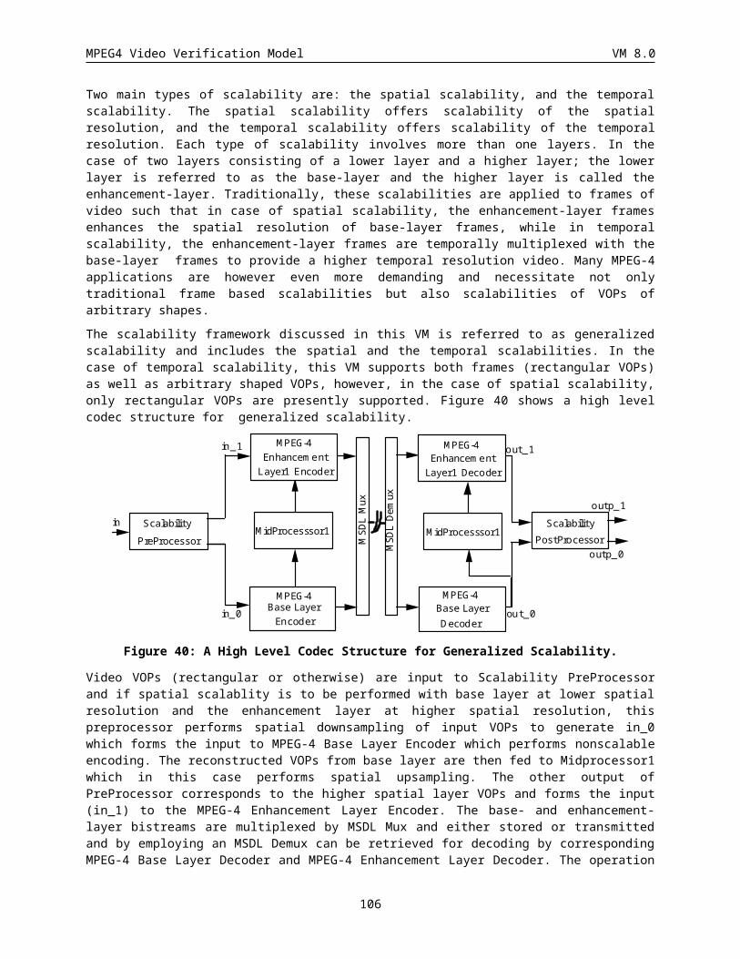
MPEG4 Video Verification Model VM 8.0
highpass leading TypeB
(3taps) trailing TypeB
Table 14 Extension method for the analysis wavelet filters
synthesis filter boundary extension
lowpass leading TypeB
(3taps) trailing TypeA
highpass leading TypeA
(9taps) trailing TypeB
Table 15 Extension method for the synthesis wavelet filters
Type A and Type B extensions at the leading and the trailing boundaries are shown in and Figure 59. In these figures, the samples are shown with letters such as ‘a’, ‘b’, ’c’, and each arrow indicates the symmetry point produced by the extension.
Figure 58 Symmetrical extensions at the leading boundary
Figure 59 Symmetrical extensions at the trailing boundary
At the synthesis stage, each sample shown in and Figure 59 should be interpreted as downsampled data.Downsample
At the analysis stage, downsampling for each band is performed as Figure 60.
Figure 60 Downsampling at the analysis stage
106
TypeA:
TypeB :
…v w x y z | z y x w v …
… v w x y z | y x w v …
symmetry point
Lowpass band:
Highpass band:
|a # c # e … …# w # y #|
|a’ # c’ # e’ … …# w’ # y’ #|
TypeA:
TypeB :
…e d c b a | a b c d e …
…e d c b | a b c d e …
symmetry point
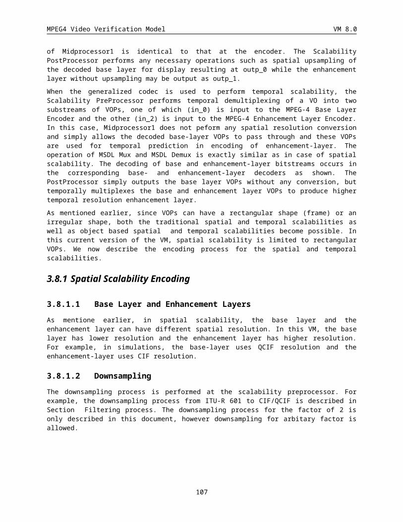
MPEG4 Video Verification Model VM 8.0
In Figure 60, the finite series “a b c ..... x y z” consisting of an even number of data is supposed to be downsampled and ‘#’ represents a sample which is disposed.
Decomposition level
The number of decomposition levels of the luminance component is defined by the encoder in the input bitstream. The chrominance components are decomposed to one level less than the luminance components.
3.10.3 Coding of the lowest subbandThe wavelet coefficients of the lowest band are coded independently from the other bands. These coefficients are quantized using an uniform midriser quantizer. After quantization of the lowest subband coefficients, a DPCM coding scheme is applied to code the quantized values as described below. Each of the current coefficients w X is predicted from three other quantized coefficients in its neighborhood, i.e. wA, wB, and wC (see Figure 61), and the predicted value is subtracted from the current coefficient. That is,
if (|wA-wB|) < | wA-wC|)
w wx Cwx = wx - wx
else
w wx Awx = wx - wx
The coefficients after the DPCM are then encoded using an adaptive arithmetic coder. First the minimum value of the coefficients is found. This value, “band_offset”, is subtracted from all the coefficients to limit their lower bond to zero. Next, the maximum value of the coefficients is found (“band_max_value”). The values “band_offset” and “band_max_value” are put into bitstream.. The arithmetic coder model is initialized with an uniform distribution of “band_max_value” seeds and then the coefficients are scanned and coded using the adaptive arithmetic coder.
B C
A X
Figure 61 DPCM coding of lowest band coefficients
3.10.4 ZeroTree Coding of the Higher BandsIn order to achieve a wide range of scalability levels efficiently as needed by the application, a multiscale zerootree coding scheme is employed. Figure 62 shows the concept this technique.
107
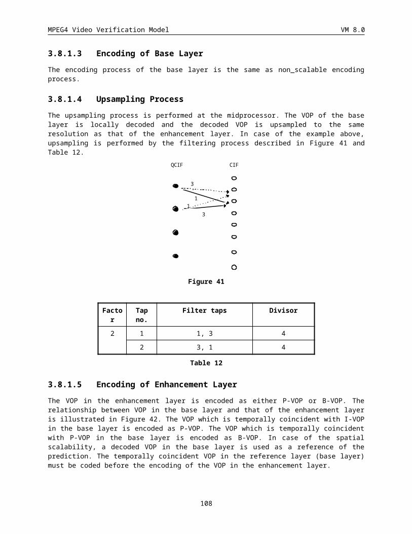
MPEG4 Video Verification Model VM 8.0
Buffer Q
Q ZTS AC
+-
-1
BS0
Buffer Q+-
-1
Q ZTS AC BS1
Q ZTS AC BSn
0
1
n
0
1
Figure 62. Multiscale Zerotree Coding
The wavelet coefficients of the first spatial (and/or SNR) layer first are quantized with the quantizer Q0. These quantized coefficients are scanned using the zerotree concept and then the significant maps and quantized coefficients are entropy coded. The output of entropy coder at this level, BS0, is the first portion of the bitstream. The quantized wavelet coefficients of the first layer are also reconstructed and subtracted from the original wavelet coefficients. These residual wavelet coefficients are fed into the second stage of the coder in which the wavelet coefficients are quantized with Q1, zerotree scanned and entropy coded. The output of this stage, BS1, is the second portion of the output bitstream. The quantized coefficients of the second stage are also reconstructed and subtracted from the original coefficients. As is shown in Figure 62, N+1 stages of the scheme provides N+1 layers of scalability. In the following sections, different modules of the scheme is briefly described.
3.10.5 QuantizationIn order to achieve a wide range of scalability levels efficiently as needed by the application, a multilevel quantization scheme is employed. The levels of quantization are defined by the encoder and specified in the bitstream. This multilevel quantization scheme provides a very flexible approach to support the right tradeoff between levels and type of scalability, complexity and coding efficiency for any application. After quantization, each wavelet coefficient is either zero or nonzero. Different quantization step sizes (one for luminance and one for chrominance) can be specified for each level of scalability. All the quantizers of the higher bands are uniform mid-rise quantizer with a dead zone 2 times the quantization step size. These quantization step sizes are specified by the encoder in the bitstream..
In order to achieve the finest granularity of SNR scalability, a bi-level quantization scheme is used for all the multiple quantizers. This quantizer is also a uniform mid rise quantizer with a dead zone 2 times the quantization step size. The coefficients that lie outside the dead zone (in the current and previous pass) are quantized with a 1 bit accuracy. The number of quantizers is equal to the maximum number of bitplanes in the wavelet transform representation. In this bi-level case, instead of the quantization step sizes, the maximum number of the bitplanes is specified in the bitstream.
108
MPEG4 Video Verification Model VM 8.0
3.10.6 Zero Tree ScanningZero-tree algorithm is based on the observation that strong correlation exists in the amplitudes of the wavelet coefficients across scales, and on the idea of partial ordering of the coefficients. The coefficient at the coarse scale is called the parent, and all coefficients at the same spatial location, and of similar orientation, at the next finer scale are that parent’s children. Figure 63 shows a wavelet tree where the parents are the children are indicated by dots and connected by lines. Since the lowest frequency subband (shown at the upper left in Figure 63) is coded separately using a DPCM scheme, the wavelet trees start from the adjacent higher bands.
Figure 63 The parent-child relationship of wavelet coefficients
In transform-based coding, it is typically true that a large percentage of the transform coefficients are quantized to zero. A substantial number of bits must be spent either encoding these zero-valued quantized coefficients, or else encoding the location of the non-zero-valued quantized coefficients. ZeroTree Coding uses a data structure called a zerotree, built on the parent-child relationships described above, and used for encoding the location of non-zero quantized wavelet coefficients. The zerotree structure takes advantage of the principle that if a wavelet coefficient at a coarse scale is “insignificant” (quantized to zero) then all wavelet coefficients of the same orientation at the same spatial location at finer wavelet scales are also likely to be “insignificant” .
Zerotrees exist at any tree node where the coefficient is zero and all the node’s children are zerotrees. The wavelet trees are efficiently represented and coded by scanning each tree from the root in the low-low band through the children, and assigning one of three symbols to each node encountered: zerotree root, value ,zerotree root, or value. A zerotree root denotes a coefficient that is the root of a zerotree. Zerotrees do not need to be scanned further because it is known that all coefficients in such a tree have amplitude zero. A valued zerotree root is a node where the coefficient has a nonzero amplitude, and all four children are zerotree roots. The scan of this tree can stop at this symbol. A value symbol identifies a coefficient with amplitude either zero or nonzero, but also with some nonzero descendant. The symbols and quantized coefficients are then losslessly encoded using an adaptive arithmetic coder.
When bi-level quantization is applied, the significant map is coded with the following symbols: zerotree root, isolated zero, valued zerotree root and value. The coefficients that are already found significant are replaced with zero symbols for the purpose of zero-tree forming in later scans. A wild card symbol is used which will be interpreted as zero symbol if a zero-tree root results as consequence of its being considered as zero symbol and will otherwise be treated as don’t care symbol and be ignored.
In order to achieve both spatial and SNR scalabilities two different scanning methods are employed in this scheme. For the spatial scalability, the wavelet coefficients are scanned in the subband by subband fashion, from the lowest to the highest frequency subbands. For the SNR scalability, the wavelet coefficients are scanned in each tree from the top to the bottom. The scanning method is defined in the bitstream.
109
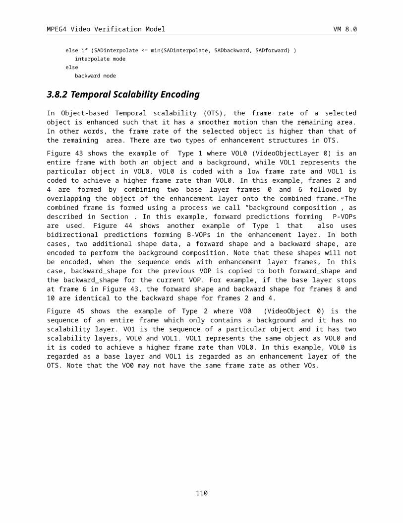
MPEG4 Video Verification Model VM 8.0
3.10.7 Entropy codingThe zero-tree symbols and the quantized values are coded using an adaptive arithmetic coder. The arithmetic coder adaptively tracks the statistics of the zerotrees. Symbols and quantized coefficient values generated by the zerotree stage are all encoded using an adaptive arithmetic coder and a three-symbol alphabet. The list of other nonzero quantized coefficients that correspond one-to-one with the valued zerotree root symbols are encoded using an alphabet that does not include zero. The remaining coefficients, which correspond one-to-one to the value symbols, are encoded using an alphabet that does include zero. For any node reached in a scan that is a leaf with no children, neither root symbol can apply. Therefore, some bits can be saved by not encoding any symbol for this node and encoding the coefficient using the alphabet that includes zero.
In the arithmetic coder, three different tables (type, valz, valnz) must be coded at the same time. The statistics of each table is different and therefore the arithmetic coder must track at least three different probability models, one for each table. In current implementation, five different models are used for coding of these values: 1) type; 2) DC to code the nonzero quantized coefficients of the low-low band; 3) AC to code the nonzero quantized coefficients of the other 3 low resolution bands; 4) VaLNZ to code other nonzero quantized coefficients that correspond one-to-one with the valued zerotree root symbols and 5) VALZ to code the remaining coefficients which correspond one-to-one to the value symbols. For each wavelet coefficient in any wavelet block, first the coefficient is quantized, then its type and value are calculated, and last these values are arithmetic coded. The probability model of the arithmetic coder is switched appropriately for each table. For each model, the alphabet range is found, and this value, max_alphabet, is put into bitstream in the following format:
extension (1 bit) value (7 bits)
.
.
.
.
.
.
The following scripts shows how max_alphabet is encoded:while ( max_alphabet/128 > 0 ){
extension = 1;put (band_max_value%128) in valuemax_alphabet = max_alphabet>>7;
}extension = 0;put max_alphabet in value
Each arithmetic model is initialized with an uniform distribution. For multiple-level bi-level quantizers, the four symbols, namely zerotree root, isolated zero, valued zerotree root and value, and the 1 bit bi-level quantized refinement values are entropy coded using the arithmetic coder.
The output of the coder is one single bitstream for each luminance and color component. Therefore, three different bitstreams are generated for each motion compensated residual frame. The three bitstreams are concatenated and appropriate header is added to fit in the main output bitstream of the coder. In the cases in which all of the luminance or chrominance residual components are quantized to zero, a skip code is sent to minimize the coding cost of that residual component.
110
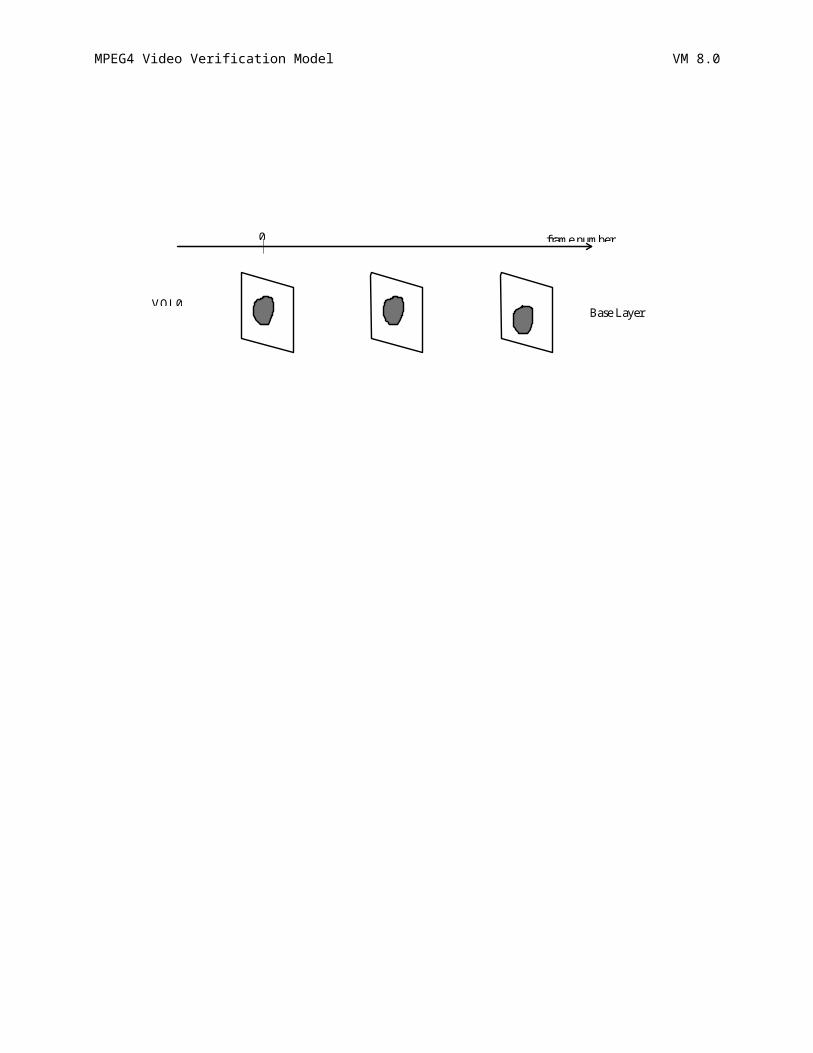
MPEG4 Video Verification Model VM 8.0
4 BITSTREAM SYNTAX
4.1 Definitions/// Integer division with rounding of the result towards plus infinity. For example 3 /// 2 is rounded to 2 and -3 /// 2 is rounded to -1.
next_start_code() { No. of Bits Mnemonic
zero_bit1
1 ‘0’
while !byte_aligned()
one_bit 1 ‘1’
}
Editor’s note: This definition of this function has been modifed from MPEG 2. Byte alignment is achieved by stuffing ‘011..’ rather than all zeros. Stuffing of 1 to 8 bits is shown in the table. Additional byte stuffing is no longer allowed.
Bits to be stuffed Stuffing Codeword
1 0
2 01
3 011
4 0111
5 01111
6 011111
7 0111111
8 01111111
next_resync_marker() { No. of Bits Mnemonic
zero_bit1
1 ‘0’
while !byte_aligned()
one_bit 1 ‘1’
}
Editor’s note: This function provies similar features to next_start_code() for resync_marker
The function nextbits_bytealigned() permits comparison of a bitstream with the next bits to be decoded in the bitstream at which the first bit is byte aligned.
The function next_bits() permits comparison of bitstreams with the next bits to be decoded.
111
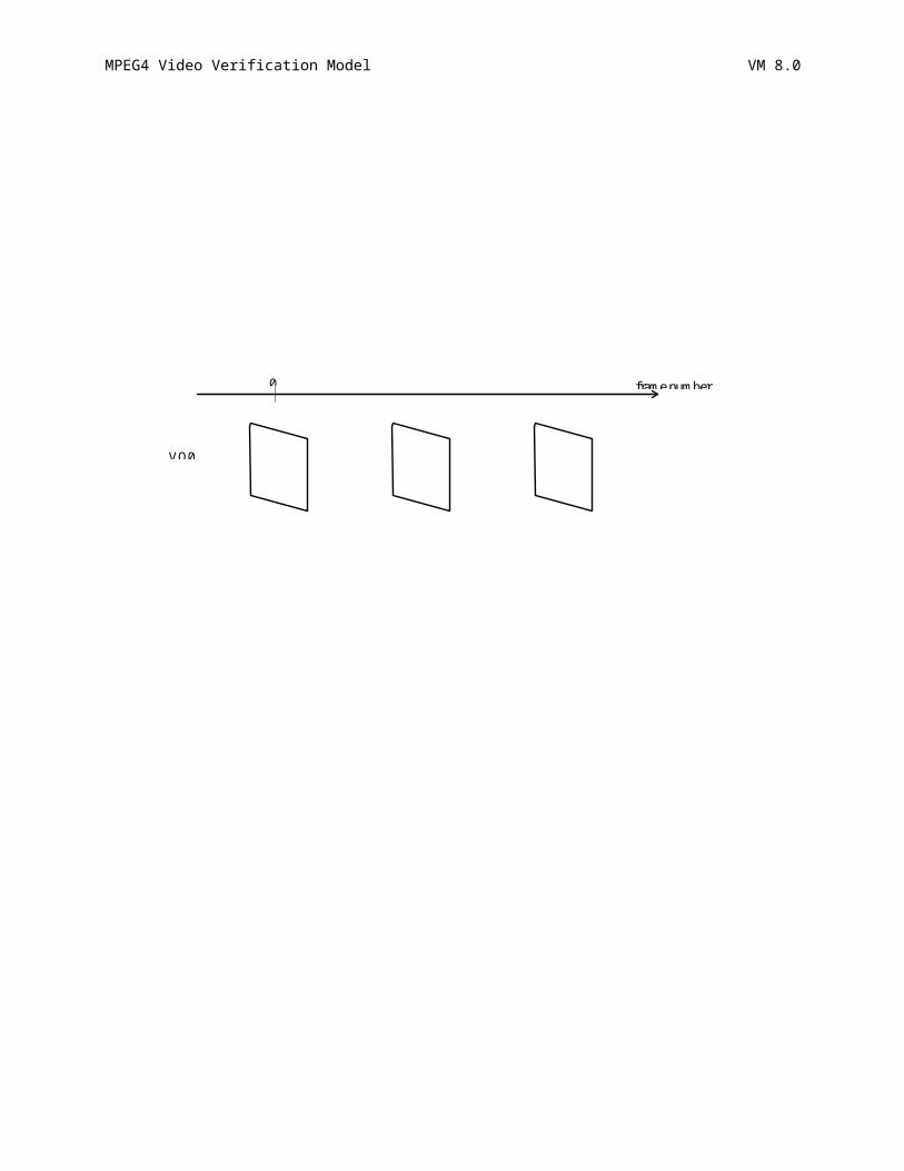
MPEG4 Video Verification Model VM 8.0
4.2 General StructureThe syntax consists of the following class hierarchy:
· VideoSession (VS)
· VideoObject (VO)
· VideoObjectLayer (VOL) or TextureObjectLayer(SOL)
· Group of VideoObjectPlane (GOV)
· VideoObjectPlane (VOP)
Within the context of video experiments, a VS is a collection of one or more VO’s. A VO can consist of one or more layers. These layers can correspond to either video or textures. The video object layers are called VideoObjectLayers (VOL's) and the texture layers are called TextureObject-Layer(SOLs). Each VOL consists of an ordered sequence of snapshots in time called VOPs. Thus there can be several VO’s (VO0, VO1, ..) in a VS and for each VO, there can be several layers (VOL0, VOL1,.., or SOL1, SOL2,..). Each VOL consists of time sequence of VOPs (VOP0, VOP1,..), which are basically snapshots in time. The GOV layer is an optional layer, so the bitstream can have any(include none) number of the GOP header, and the frequency of the GOV header is an encoder issue. Since the GOV header indicates the absolute time, it may be used for random access and error recovery purpose. In some profile, the GOV header shall be followed by the I-VOP.A VO can be of arbitrary shape (rectangular is a special case). For single layered coding only one VOL (VOL0) or one SOL (SOL0) exists per VO. Figure 63 shows the hierarchical structure of the syntax.
For the purpose of conducting core experiments the bitstreams for the VideoSession and each of the VideoObject’s and VideoObjectLayer’s/TextureObjectLayers's are stored in separate files. The multiplexing of these bitstreams will be provided by the MSDL.
VS0
VO0
VS1
VO1
VOL0 VOL1
GOV0 GOV1
VOP0 .....VOPn VOPn+1 .....VOPm
Video Session
Video Object
Video Object Layer
Group of Video Object Plane
Video Object Plane
Figure 64: Hierarchy in the proposed video syntax
4.3
112
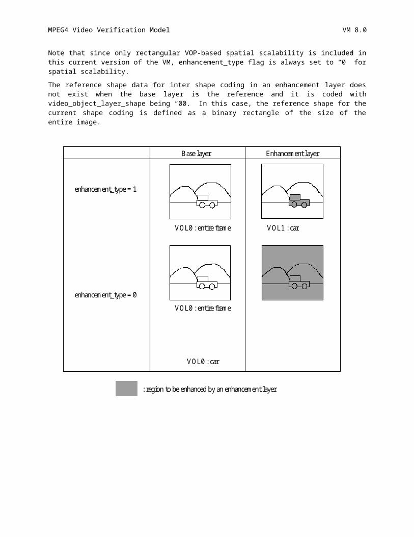
MPEG4 Video Verification Model VM 8.0
Video Session Class
4.3.1 Video Session Class
Syntax No. of bits Mnemonic
VideoSession() {
video_session_start_code sc+8=32
do* {
VideoObject()
}while (nextbits_bytealigned()== video_object_start_code)
next_start_code()
video_session_end_code sc+8=32
}
* concurrent loop solution to be provided by MSDL.
sc
This code is intended to be used in combination with additional bits, for the purpose of the synchronization. Its binary representation is 23 zeros followed by a 1 (000000000000000000000001), or its hexadecimal representation is ‘000001’.
video_session_start_code
This code cannot be emulated by any combination of other valid bits in the bitstream, and is used for synchronization purpose. Its value is that of the sc followed by 'B0' in hexadecimal.
video_session_end_code
This code cannot be emulated by any combination of other valid bits in the bitstream, and is used for synchronization purpose. Its value is that of the sc followed by 'B1' in hexadecimal. video_session_end_code resets all data relative to VOPs. In other words, different sessions are treated completely independently.
113
MPEG4 Video Verification Model VM 8.0
4.4 Video Object Class
4.4.1 Video Object
Syntax No. of bits Mnemonic
VideoObject() {
video_object_start_code sc+3=27
video_object_id 5
do{
VideoObjectLayer()
}while(nextbits_bytealigned()==video_object_layer_start_code)
do{
textureObjectLayer()
}while(nextbits_bytealigned()==texture_object_layer_start_code)
next_start_code()
}
video_object_start_code
This is a unique code of length 27 bits (sc+3) that preceeds the video_object_id.
video_object_id
This is a 5-bit code which identifies a video object in a scene being processed.
114
MPEG4 Video Verification Model VM 8.0
4.5 Video Object Layer Class
4.5.1 Video Object Layer
Syntax No. of bits Mnemonic
VideoObjectLayer() {
video_object_layer_start_code sc+4=28
video_object_layer_id 4
video_object_layer_shape 2
if ( video_object_layer_shape == ‘00’) {
video_object_layer_width 13
video_object_layer_height 13
}
not_8_bit 1
obmc_disable 1
if (not_8_bit) {
quant_precision 4
bits_per_pixel 4
}
video_object_layer_shape_effects 4
if(video_object_layer_shape_effects==‘0001’
||video_object_layer_shape_effects==‘0011’
||video_object_layer_shape_effects==‘0100’
||video_object_layer_shape_effects == ‘0101’)
video_object_layer_feather_dist 3
if(video_object_layer_shape_effects==‘0100’
||video_object_layer_shape_effects == ‘0101’) {
for(i=0;i<video_object_layer_feather_dist;i++)
feathering_filter(); 8*15
}
video_object_layer_sprite_usage 2
if (video_object_layer_sprite_usage!=SPRITE_NOT_USED) {
if(video_object_layer_sprite_usage==STATIC_SPRITE
¦¦video_object_layer_sprite_usage==ON_LINE_SPRITE) {
115
MPEG4 Video Verification Model VM 8.0
sprite_hdim 13
sprite_vdim 13
}
if(video_object_layer_sprite_usage==STATIC_SPRITE
¦¦video_object_layer_sprite_usage==ON-LINE_SPRITE) {
sprite_Left_Edge 13
sprite_Top_Edge 13
}
no_of_sprite_points 6
warping_accuracy 2
lighting_change_in_sprite 1
}
if (video_object_layer_shape!=’00’)
sadct_disable 1
video_object_layer_quant_type 1
if (video_object_layer_quant_type) {
load_intra_quant_mat 1
if (load_intra_quant_mat) {
i=0;
do
intra_quant_mat[i] 8
while (intra_quant_mat[i] != 0
&& ++i < 64);
for (j=i; j<64; j++)
intra_quant_mat[j] =
intra_quant_mat[i-1];
}
load_nonintra_quant_mat 1
if (load_nonintra_quant_mat) {
i=0;
do
nonintra_quant_mat[i] 8
while (nonintra_quant_mat[i] != 0
&& ++i < 64);
for (j=i; j<64; j++)
nonintra_quant_mat[j] =
116
MPEG4 Video Verification Model VM 8.0
nonintra_quant_mat[I-1];
}
if(video_object_layer_shape==‘10’){
disable_gray_quant_update 1
load_gray_intra_quant_mat 1
if(load_gray_intra_quant_mat)
i=0;
do
gray_intra_quant_mat[i] 8
while (gray_intra_quant_mat[i]!=0
&& ++i < 64);
for (j=i; j<64; j++)
gray_intra_quant_mat[j] =
gray_intra_quant_mat[i-1];
}
load_gray_nonintra_quant_mat 1
if (load_gray_nonintra_quant_mat) {
i=0;
do
gray_nonintra_quant_mat[i] 8
while (gray_nonintra_quant_mat[i]!=0
&& ++i < 64);
for (j=I; j<64; j++)
gray_nonintra_quant_mat[j] =
gray_nonintra_quant_mat[i-1];
}
}
}
Complexity_estimation_disable 1
if (!Complexity_estimation_disable){
Parameter_list 8
Estimation_method 2
if (Estimation_method ==’00’){
INTRA 1 INTRA+Q 1 INTER 1
117
MPEG4 Video Verification Model VM 8.0
INTER4V 1
INTER+Q 1 INTERPOLATE MC+Q 1 FORWARD MC+Q 1 BACKWARD MC+Q 1 H.263 PB DIRECT 1
Not Coded 1
Zig-zag_DCT_coeff 1
Half_pel_advanced_prediction 1
Half_pel_normal_pred 1
VLC_symbol 1
Shape_coding_parameters {
t.b.d …….. 1
}
Scalability_parameters {
t.b.d …….. 1
}
Sprite_coding_parameters {
t.b.d …….. 1
}
}
if (Estimation_method ==’xx’){
t.b.d ……..
}
}
error_resilient_disable 1
if (!error_resilient_disable) {
data_partitioning 1
reversible_VLC 1
}
intra_acdc_pred_disable 1
separate_motion_shape_texture 1
if(video_object_layer_sprite_usage==STATIC_SPRITE){
encodeSpritePiece()
}
Scalability 1
if (scalability) {
118
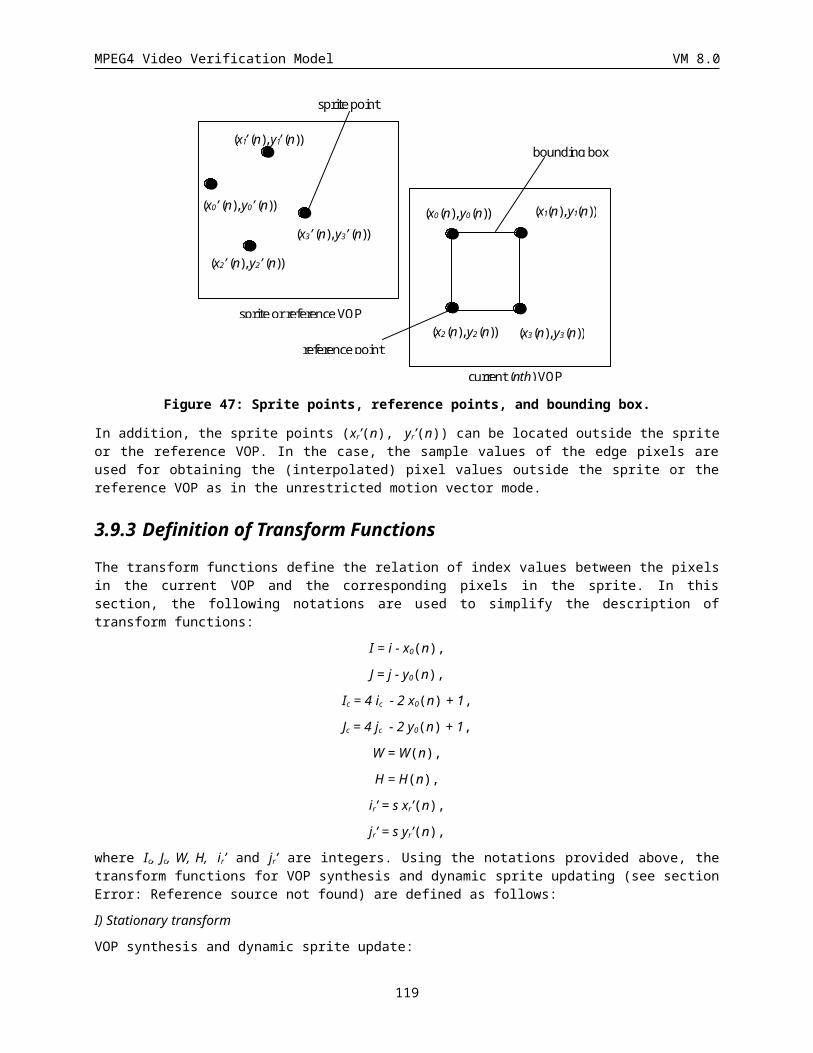
MPEG4 Video Verification Model VM 8.0
ref_layer_id 4
ref_layer_sampling_direc 1
hor_sampling_factor_n 5
hor_sampling_factor_m 5
vert_sampling_factor_n 5
vert_sampling_factor_m 5
enhancement_type 1
}
do {
VideoObjectPlane()
}while(nextbits_bytealigned()==video_object_plane_start_code)
next_start_code()
}
video_object_layer_start_code
This is a unique code of length 28 bits (sc+4) that preceeds the video_object_layer_id.
video_object_layer_id
This is a 4-bit code which identifies a video object layer for a video object being processed.
video_object_layer_shape
This is a 2-bit code which identifies the shape type of video object layer as shown in Table 16.
video_object_layer_shape Code
rectangular 00
binary 01
gray-scale 10
Binary-shape-only 11
Table 16 Video Object Layer shape types
This flag is “00” if a VOL shape is rectangular, “01” if a VOL has a binary shape (i.e. if each pixel of the rectangle defined by video_object_layer_width and video_object_layer_height is either part of a VOL or not), and “10” if a VOL shape is defined by grey scale data (i.e. if each pixel of the rectangle defined by video_object_layer_width and video_object_layer_height is to be linearly combined with the pixels of other VOLs at the same spatial location). The flag is “11” if the VOL consists of only binary shape and no texture.
video_object_layer_width, video_object_layer_height
These two codes define the picture size for the session, in pixels unit (zero values are forbidden). This is also the size of the unique VOL of the session.
not_8_bit
This one bit flag is set when the video data precision is not 8 bits per pixel.
quant_precision
119
MPEG4 Video Verification Model VM 8.0
This field specifies the number of bits used to represent quantiser parameters. Values between 3 and 9 are allowed. When not_8_bit is zero, and therefore quant_precision is not transmitted, it takes a default value of 5.
bits_per_pixel
This field specifies the video data precision in bits per pixel. It may take different values for different video object layers within a single video object. A value of 12 in this field would indicate 12 bits per pixel. This field may take values between 4 and 12.
When not_8_bit is zero and bits_per_pixel is not present, the video data precision is always 8 bits per pixel, which is equivalent to specifying a value of 8 in this field.
video_object_layer_sprite_usage
This 2-bit code is to indicate the usage of sprite coding or global motion compensation (GMC).
0x00 means that no sprite is used in the coding. Mnemonic is SPRITE_NOT_USED.
0x01 means that a sprite is being used directly (i.e., no predictions are made on the basis of the sprite) to generate some or all of the VOPs in this VOL (i.e., static sprite). The static sprite is assumed to have been transmitted as an I-VOP with possible additional pieces transmitted in the future also as I-VOPs and residual update pieces also transmitted as I-VOPs, but using the quantization of Non-Intra macroblocks. Mnemonic is STATIC_SPRITE.
0x02 means that a sprite is used in predictive coding for some or all of the VOPs in this VOL. The sprite is being constructed on-line and the mechanism for building the sprite is on. Mnemonic is ON-LINE_SPRITE.
0x03 means that GMC is used in predictive coding for some or all of the VOPs in this VOL. GMC is an extension of on-line sprite coding where blending factor is always 1 and the size of the sprite is just the same as that of the reference VOP. This means that the previous reconstructed VOP is regarded as an on-line sprite, and no additional memory for a sprite is needed. Mnemonic is GMC.
sprite_hdim
This 13-bit field defines the horizontal dimension of the sprite.
sprite_vdim
This 13-bit field defines the vertical dimension of the sprite.
sprite_Left_Edge
This 13-bit field defines the left edge of the sprite.
sprite_Top_Edge
This 13-bit field defines the top edge of the sprite.
no_of_sprite_points
This 6-bit number represents the number of points for sprite warping. Different transformations are used for different settings of number of points. See the next section for details of these transformations.
Number of points Transformations
0 stationary
1 translation
2,3 affine
4 perspective
Table 17 Transformations for number of points
0 points is used for stationary VOL's. An affine transforms are used if there are 1, 2, or 3 points. The case of 1 point is separated from 2 and 3 points because of its possible special implementation and wide usage. A perspective transform is applied if there are 4 points. Local affine is used for more than 4 points.
120
MPEG4 Video Verification Model VM 8.0
Note that if no_of_sprite_points is zero, when video_object_layer_sprite_usage indicates sprite usage, the warping is understood to be identity (stationary motion for sprite) and no coordinates need to be coded.
warping_accuracy
This is a 2-bit code which indicates the quantization accuracy of motion vectors used in the warping process for static/dynamic sprites and global motion compensation.
Codewords for warping_accuracy.
warping_accuracy Code
1/2 pixel 00
1/4 pixel 01
1/8 pixel 10
1/16 pixel 11
lighting_change_in_sprite
This flag indicates whether there is any lighting change during the sprite warping. 0 is FALSE and 1 is TRUE.
sadct_ disable
A bit code whose value is ‘1’ when SA-DCT is disabled. The default value of disable_sadct is always ‘1’. When enabled, all DCT transforms are replaced by SA-DCT as described in Sec.
video_object_layer_quant_type
A 1-bit code which indicates the type of quantization method selected. When it has a value of 0, H.263 quantization method is selected, otherwise, MPEG-1/2 quantization method is selected.
load_intra_quant_mat
A 1-bit code which indicates whether the default matrix for visually weighting DCT coefficients of intra macroblocks is selected or if a new matrix for visually weighting of DCT coefficients of intra macroblocks is to be loaded.
intra_quant_mat[i]
This is a one dimensional (1d) array of up to 64 values (8-bits per value expressed in the range 1 to 255) for visual weighting of DCT coefficients of intra macroblocks. The values in the 1d array are in the same order as that obtained by zigzag scanning of an 8x8 two-dimensional array. A decoded value of 0 indicates that the matrix is truncated and the remaining, non-transmitted values are set equal to the last non-zero value. When no values are transmitted (i.e., the first decoded value is zero) the default value for each array entry is 16.
load_nonintra_quant_mat
A 1 bit code which indicates whether the default matrix for visually weighting DCT coefficients of nonintra macroblocks is selected or if a new matrix for visually weighting of DCT coefficients of nonintra macroblocks is to be loaded.
nonintra_quant_mat[i]
This is a one dimensional (1d) array of up to 64 values (8-bits per value expressed in the range 1 to 255) for visual weighting of DCT coefficients of nonintra macroblocks. The values in the 1d array are in the same order as that obtained by zigzag scanning of an 8x8 two-dimensional array. A decoded value of 0 indicates that the matrix is truncated and the remaining, non-transmitted values are set equal to the last non-zero value. When no values are transmitted (i.e., the first decoded value is zero) the default value for each array entry is 16.
121
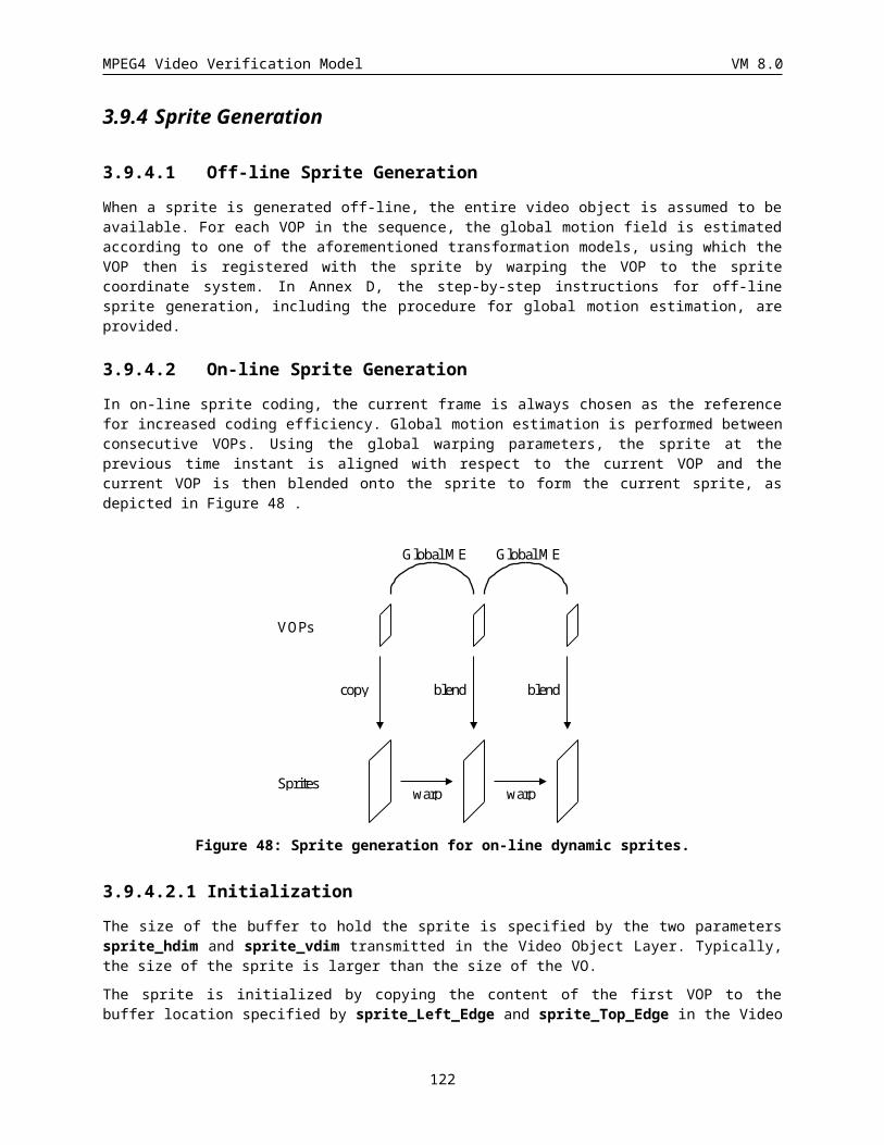
MPEG4 Video Verification Model VM 8.0
disable_gray_quant_update
A 1-bit code which indicates the quantizer for grayscale alpha mask is to be updated when set to “0”. The method for updating the quantizer is specified in the next section (See the semantics for VOP_gray_quant).
load_gray_intra_quant_mat
A 1-bit code which indicates whether the matrix for visually weighting DCT coefficients of intra macroblocks of texture is used as that of a gray-scale alpha mask or if a new matrix for visually weighting of DCT coefficients of intra macroblocks of a gray-scale alpha mask is to be loaded.
gray_intra_quant_mat[i]
This is an one dimensional (1d) array of up to 64 values (8-bits per value expressed in range 1 to 255) for visual weighting of DCT coefficients of gray-scale alpha masks of intra macroblocks. The values in the 1d array are in the same order as that obtained by zig-zag scanning of a 8x8 two-dimensional array. A decoded value of 0 indicates that the matrix is truncated and the remaining, non-transmitted values are set equal to the last non-zero value. When no values are transmitted (i.e., the first decoded value is zero) the default value for each array entry is 16.
load_gray_nonintra_quant_mat
A 1 bit code which indicates whether the matrix for visually weighting DCT coefficients of nonintra macroblocks of texture is used as that of gray-scale alpha or if a new matrix for visually weighting of DCT coefficients of gray-scale alpha masks of nonintra macroblocks is to be loaded.
gray_nonintra_quant_mat[i]
This is an one dimensional (1d) array of up to 64 values (8-bits per value expressed in range 1 to 255) for visual weighting of DCT coefficients of gray-scale alpha masks of nonintra macroblocks. The values in the 1d array are in the same order as that obtained by zig-zag scanning of a 8x8 two-dimensional array. A decoded value of 0 indicates that the matrix is truncated and the remaining, non-transmitted values are set equal to the last non-zero value. When no values are transmitted (i.e., the first decoded value is zero) the default value for each array entry is 16.
error_resilient_disable
A bit code whose value is 1 when error resilient coding is disabled. The value of this flag affects the techniques used for motion vector prediction. This resynchronisation strategy only applies in the single VOP case.
data_partitioning
A bit code whose value is 1 when the motion and texture data between the two resync. markers are partitioned as described in the Section 6.3
reversible_VLC
A bit code whose value is 1 when reversible VLCs are to be used to generate the bitstream.
intra_acdc_pred_disable
A bit code whose value is 1 when AC/DC prediction of intra coded blocks is disabled. In normal coding, AC/DC prediction of intra macroblocks is always enabled.
obmc_disable
A bit code whose value is 1 when overlapped motion compensation for luminance is not performed. In this case, motion compensation for luminance and chromiance is the same.
Separate_motion_shape_texture
122
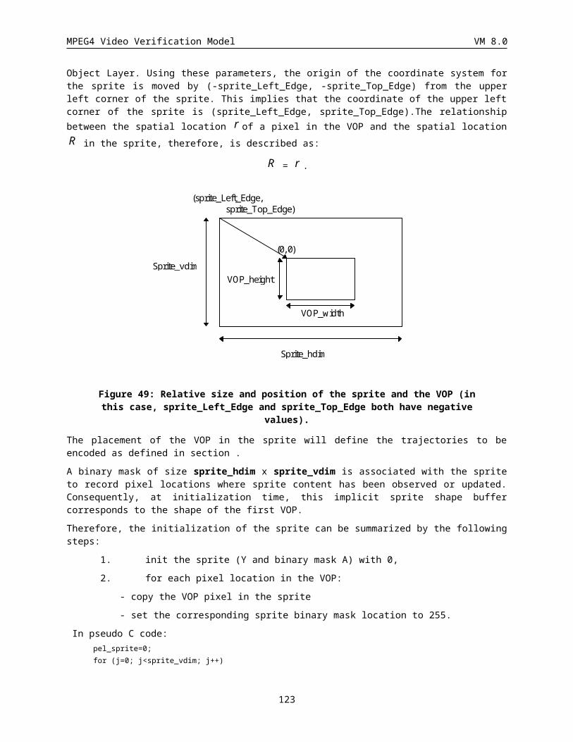
MPEG4 Video Verification Model VM 8.0
This flag is “1” if all the coding data (e.g. motion, shape, texture, etc) for the VOP are grouped together. It is “0” if the coding data are grouped macroblock per macroblock.
EncodeSpritePiece ()
This function encodes a selected region of the sprite object or residual. It also encodes the parameters required by the decoder to properly incorporate the pieces. All the pieces will be encoded as I-VOPs, but object pieces use the quantization of Intra macroblocks, and the update pieces use the quantization of Non-intra macroblocks. In the Video Object Layer, the initial sprite piece is transmitted as an I-VOP with the quantization of Intra macroblocks. This function is also called from the Video Object Plane to encode additional sprite object pieces and residual pieces. The parameters are encoded as fixed length values. The parameters are piece_width, piece_height, piece_xoffset, and piece_yoffset. The piece_width and piect_height are measured in number of macroblocks. Piece_xoffset specifies the horizontal offset location, measured in macroblock from the left edge of the sprite object, of the initial piece into the sprite object buffer at the decoder. Piece_yoffset specifies the vertical offset location, measured in macroblock from the top edge of the sprite object, of the initial piece into the sprite object buffer at the decoder.
Syntax No. Of bits Mnemonic
encodeSpritePiece() {
piece_width 9
piece_height 9
piece_xoffset 9
piece_yoffset 9
sprite_shape_texture ()
}
piece_width
This value specifies the width of the sprite piece measured in macroblock.
Piece_height
This value specifies the height of the sprite piece measured in macroblock.
Piece_xoffset
This value specifies the horizontal offset location, measured in macroblock from the left edge of the sprite object.
Piece_yoffset
This value specifies the vertical offset location, measured in macroblock from the top edge of the sprite object.
Sprite_shape_texture ()
Sprite shape and texture are treated as an I-VOP and therefore coded using the I-VOP method in VideoObjectLayer class, but while sprite object pieces use the quantization of Intra macroblocks, the update pieces use the quantization of Non-intra macroblocks. The shape information for the entire sprite is transmitted in the VOL as part of the I-VOP. No shape information is transmitted as part of the VOP with the remaining sprite pieces and residual image pieces.
Scalability
This is a 1-bit flag which indicates if the current layer uses scalable coding. If the current layer is used as the base-layer, this flag is ‘0’.
Ref_layer_id
123
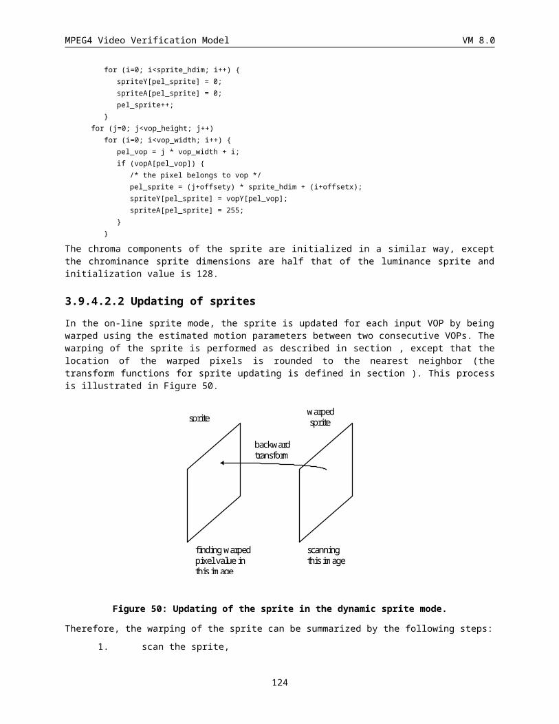
MPEG4 Video Verification Model VM 8.0
This is a 4-bit code which indicates the layer to be used as reference for the prediction(s) in the case of scalability. It can have a value between 0 and 15.
Ref_layer_sampling_direc
This is a 1-bit flag whose value when “0” indicates that the reference layer specified by ref_layer_id has the same or lower resolution as the layer being coded. Alternatively, a value of “1” indicates that the resolution of reference layer is higher than the resolution of layer being coded resolution.
Hor_sampling_factor_n, hor_sampling_factor_m
These are 5-bit quantities in range 1 to 31 whose ratio hor_sampling_factor_n/hor_sampling_factor_m indicates the resampling needed in horizontal direction; the direction of sampling is indicated by ref_layer_sampling_direc.
Vert_sampling_factor_n, vert_sampling_factor_m
These are 5-bit quantities in range of 1 to 31 whose ratio vert_sampling_factor_n/vert_sampling_factor_m indicates the resampling needed in vertical direction; the direction of sampling is indicated by ref_layer_sampling_direc.
Enhancement_type
This is a 1-bit flag which indicates the type of an enhancement structure in a scalability. It has a value of “1” when an enhancement layer enhances a partial region of the base layer. It has a value of “0” when an enhancement layer enhances entire region of the base layer. The default value of this flag is “0”.
Video_object_layer_shape_effects
This is a 4-bit code which identifies which, if any, of the special effects to create a grayscale mask from a binary one is used.
Video_object_layer_shape_effects Code
No Effects 0000
Linear Feathering 0001
Constant Alpha 0010
Linear Feathering and Constant Alpha 0011
Feathering Filter 0100
Feathering Filter and Constant Alpha 0101
Table 18 video_object_layer_feather_dist
This is a 3-bit code that specifies an integer of over how many pixels from an edge to feather the binary alpha masks. When used in conjunction with the Feathering Filter Mode, this specifies the number of iterations.
Feathering_filter()
120 bits(15 entries of 8bit FLC) code specifies a feathering filter for each iteration.
Complexity_estimation_disable
A single bit flag that indicates the presence of decoding complexity estimation by decoding statistics parameters
124
MPEG4 Video Verification Model VM 8.0
INTRA: flag for intra type macroblock countingINTRA+Q: flag for intra+Q type macroblock countingINTER: flag for inter type macroblock countingINTER4V: flag for inter4v type macroblock counting
INTER+Q: flag for inter+Q type macroblock countingINTERPOLATE MC+Q: flag for interpolate type macroblock countingFORWARD MC+Q: flag for forward prediction type macroblock countingBACKWARD MC+Q: flag for backward prediction type macroblock countingH.263 PB DIRECT: flag for H.263 direct type macroblock countingNot Coded: flag for not-coded type macroblock counting
Zig-zag_DCT_coeff: flag for statistic of DCT coefficients
Half_pel_advanced_prediction: flag for half pel advanced prediction vector counting
Half_pel_normal_pred: flag for half pel normal prediction vector counting
VLC_symbol: flag for statistic of VLD operations
Shape_coding_parameters: flag for shape coding parameters (t.b.d.)
Scalability_parameters: flag for scalability parameters (t.b.d.)
Sprite_parameters: flag for shape coding parameters (t.b.d.)
125
MPEG4 Video Verification Model VM 8.0
4.6 Group Of VOPs class
4.6.1 Syntax of Group of VideoObjectPlane
group_of_VideoObjectPlane() { No. Of bits Mnemonic
group_start_code 32 bslbf
VOP_time_increment_resolution 15 uimsbf
marker_bit 1 bslbf
time_code 18 bslbf
closed_gov 1 uimsbf
broken_link 1 uimsbf
do {
group_of_VideoObjectPlane()
}while(nextbits_bytealigned()==group_start_code)
next_start_code()
}
group_start_code
The group_start_code is the unique code of length of 32bit. It identifies the beginning of a GOV header.
VOP_time_increment_resolution
The VOP_time_increment_resolution is a 15bit unsigned integer that indicates the resolution of the VOP_time_increment in terms of number of ticks within one modulo time (one second in this case). The value of zero is forbidden.
Time_code
This is a 18-bit integer containing the following: time_code_hours, time_code_minutes, marker_bit and time_code_seconds as shown in Table1. The parameters correspond to those defined in the IEC standard publication 461 for “time and control codes for video tape recorders”. The time code refers to the first plane (in display order) after the GOV header.
Time_code range of value No. Of bits Mnemonic
time_code_hours 0 – 23 5 uimsbf
time_code_minutes 0 – 59 6 uimsbf
marker_bit 1 1 bslbf
126
MPEG4 Video Verification Model VM 8.0
time_code_seconds 0 – 59 6 uimsbf
Table 19 time_code
closed_gov
This is a one-bit flag which indicates the nature of the predictions used in the first consecutive B-VOPs (if any) immediately following the first coded I-VOP after the GOV header .The closed_gov is set to ‘1’ to indicate that these B-VOPs have been encoded using only backward prediction or intra coding. This bit is provided for use during any editing which occurs after encoding. If the previous pictures have been removed by editing, broken_link may be set to ‘1’ so that a decoder may avoid displaying these B-VOPs following the first I-VOP following the group of plane header. However if the closed_gov bit is set to ‘1’, then the editor may choose not to set the broken_link bit as these B-VOPs can be correctly decoded.
Broken_link
This is a one-bit flag which shall be set to ‘0’ during encoding. It is set to ‘1’ to indicate that the first consecutive B-VOPs (if any) immediately following the first coded I-VOP following the group of plane header may not be correctly decoded because the reference frame which is used for prediction is not available (because of the action of editing). A decoder may use this flag to avoid displaying frames that cannot be correctly decoded.
127

MPEG4 Video Verification Model VM 8.0
4.7 VideoObjectPlane Class
4.7.1 VideoObjectPlane
Syntax No. Of bits
Mnemonic
VideoObjectPlane() {
VOP_start_code sc+8=32
do {
modulo_time_base 1
} while ( modulo_time_base != “0”)
VOP_time_increment 1-15
vop_coded 1
If (vop_coded==’0’) next_start_code()
VOP_prediction_type 2
intra_dc_vlc_thr 3
if(VOP_prediction_type == “P” ||
(video_object_layer_sprite_usage != STATIC_SPRITE &&
VOP_prediction_type == SPRITE))
VOP_rounding_type 1
if (video_object_layer_sprite_usage != SPRITE_NOT_USED )
&&VOP_prediction_type == SPRITE) {
if (no_of_sprite_points > 0) {
encode_sprite_trajectory ()
}
if (lighting_change_in_sprite) {
lighting_change_factor_encode ()
}
if (video_object_layer_sprite_usage==STATIC_SPRITE ) {
if (sprite_transmit_mode != STOP) {
do {
sprite_transmit_mode = checkSpriteTransMode ()
sprite_transmit_mode 2
if ((sprite_transmit_mode == PIECE) ||
(sprite_transmit_mode == UPDATE))
128
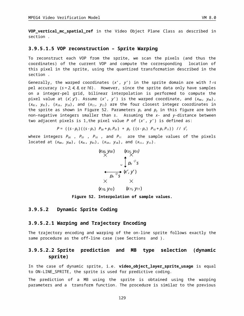
MPEG4 Video Verification Model VM 8.0
encodeSpritePiece ()
}while(sprite_transmit_mode!=STOP)
&&(sprite_transmit_mode!=PAUSE))
}
else if ( video_object_layer_sprite_usage == ON-LINE_SPRITE) {
blending_factor 8
}
}
if (video_object_layer_shape != “00”) {
VOP_width 13
marker_bit 1
VOP_height 13
VOP_horizontal_mc_spatial_ref 13
marker_bit 1
VOP_vertical_mc_spatial_ref 13
if (video_object_layer_sprite_usage==STATIC_SPRITE ) {
return();
}
if (scalability && enhancement_type)
background_composition 1
VOP_CR 1
change_CR_disable 1
}
interlaced 1
if (interlaced)
top_field_first 1
if (VOP_prediction_type==‘10’ && !scalability)
VOP_dbquant 2
else {
VOP_quant quant_precision
if(video_object_layer_shape == “10”)
VOP_gray_quant 6
}
if ((video_object_layer_shape_effects == ‘0010’) ||
(video_object_layer_shape_effects == ‘0011’) ||
(video_object_layer_shape_effects == ‘0101’)) {
129
MPEG4 Video Verification Model VM 8.0
VOP_constant_alpha 1
if (VOP_constant_alpha)
VOP_constant_alpha_value 8
}
video_object_plane_fcode_forward 3
video_object_plane_fcode_backward 3
if (!Complexity_estimation_disable){
if (estimation_method==’00’){
if (VOP_prediction_type==‘00’){
if (INTRA)
DCECS_intra 8
if (INTRA+Q)
DCECS_intra_Q 8
if (Not coded)
DCECS_Not_coded 8
if (Zig-zag_DCT_coeff)
DCECS_zig_zag_DCT VLC
if (Half_pel_advanced_prediction)
DCECS_half_pel_ap 8
if (Half_pel_normal_pred)
DCECS_ half_pel_np 8
if (VLC_symbol)
DCECS_ VLC_symbol 8
if (Shape_coding_parameters) {
DCECS_ ……t.b.d …….. Tbd
}
}
}
if (VOP_prediction_type==‘01’){
if (estimation_method==’00’){
if (INTRA)
DCECS_intra 8
if (INTRA+Q)
DCECS_intra_Q 8
if (Not coded)
DCECS_Not_coded 8
if (INTER)
130
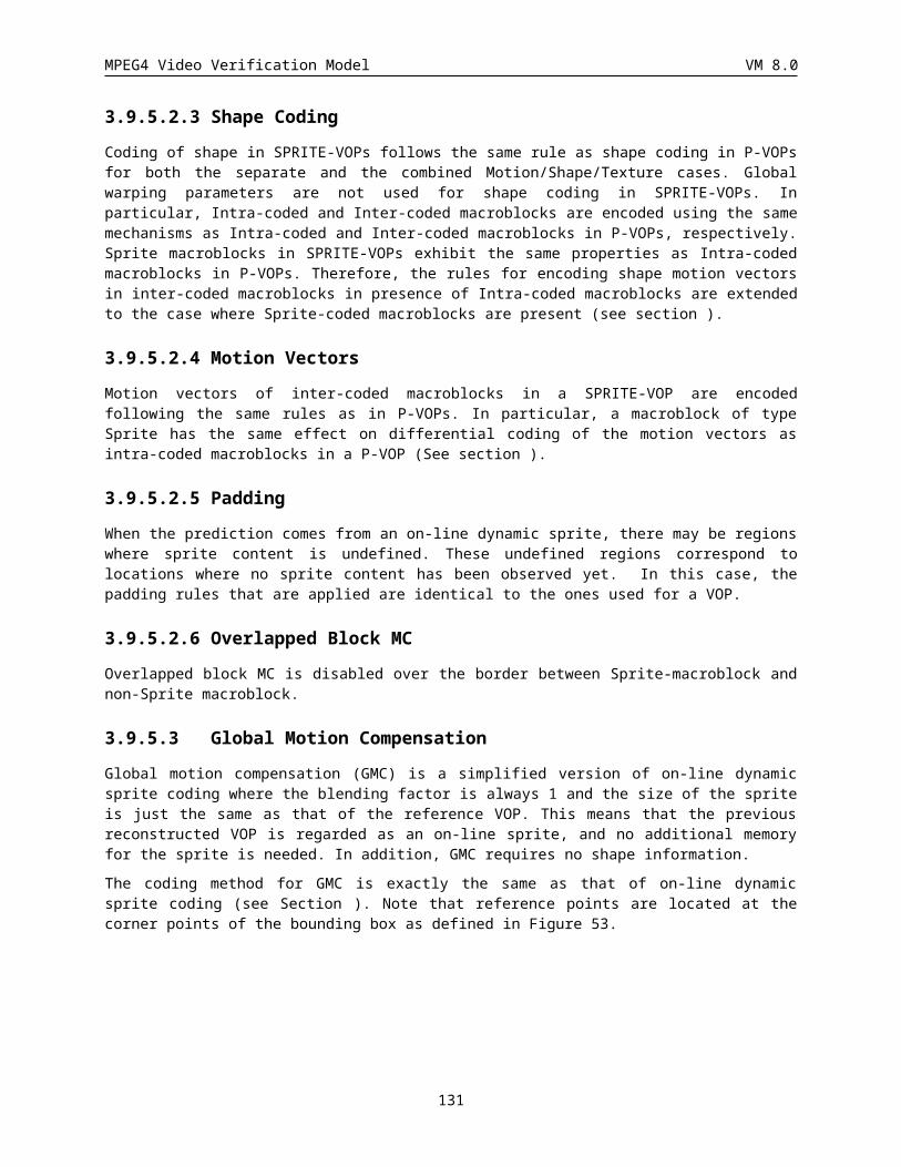
MPEG4 Video Verification Model VM 8.0
DCECS_inter 8
if (INTER4V)
DCECS_inter4v 8
if (INTER+Q)
DCECS_inter_Q 8
if (Zig-zag_DCT_coeff)
DCECS_zig_zag_DCT VLC
if (Half_pel_advanced_prediction)
DCECS_half_pel_ap 8
if (Half_pel_normal_pred)
DCECS_ half_pel_np 8
if (VLC_symbol)
DCECS_ VLC_symbol 8
if (Shape_coding_parameters) {
DCECS_ ……t.b.d …….. Tbd
}
}
if (estimation_method==’00’){
if (VOP_prediction_type==‘10’){
if (INTRA)
DCECS_intra 8
if (INTRA+Q)
DCECS_intra_Q 8
if (Not coded)
DCECS_Not_coded 8
if (INTER)
DCECS_inter 8
if (INTER4V)
DCECS_inter4v 8
if (INTER+Q)
DCECS_inter_Q 8 if (INTERPOLATE MC+Q)
DCECS_interpolate8
if (FORWARD MC+Q) DCECS_forward
8 if (BACKWARD MC+Q)
DCECS_backward8
131
MPEG4 Video Verification Model VM 8.0
if (H.263 PB DIRECT) DCECS_direct_h263
8
if (Zig-zag_DCT_coeff)
DCECS_zig_zag_DCT VLC
if (Half_pel_advanced_prediction)
DCECS_half_pel_ap 8
if (Half_pel_normal_pred)
DCECS_ half_pel_np 8
if (VLC_symbol)
DCECS_ VLC_symbol 8
if (Shape_coding_parameters) {
DCECS_ ……t.b.d …….. Tbd
}
}
}
if (estimation_method==’00’){
if (VOP_prediction_type==‘11’){
If (INTRA)
DCECS_intra 8
If (INTRA+Q)
DCECS_intra_Q 8
If (Not coded)
DCECS_Not_coded 8
If (INTER)
DCECS_inter 8
if (INTER4V)
DCECS_inter4v 8
if (INTER+Q)
DCECS_inter_Q 8 if (INTERPOLATE MC+Q)
DCECS_interpolate8
if (FORWARD MC+Q) DCECS_forward
8 if (BACKWARD MC+Q)
DCECS_backward8
if (H.263 PB DIRECT) DCECS_direct_h263
8
132
MPEG4 Video Verification Model VM 8.0
if (Zig-zag_DCT_coeff)
DCECS_zig_zag_DCT VLC
if (Half_pel_advanced_prediction)
DCECS_half_pel_ap 8
if (Half_pel_normal_pred)
DCECS_ half_pel_np 8
if (VLC_symbol)
DCECS_ VLC_symbol 8
if (Shape_coding_parameters) {
DCECS_shape ……t.b.d …….. t.b.d.
}
if (Sprite_coding_parameters) {
DCECS_ sprite ……t.b.d …….. t.b.d.
}
}
}
}
if (!scalability) {
if (!separate_motion_shape_texture)
if(error_resilience_disable)
combined_motion_shape_texture_coding()
else
do{
do{
combined_motion_shape_texture_coding()
} while (nextbits_bytealigned() != 0000 0000 0000 0000)
if(nextbits_bytealigned()!=000 0000 0000 0000 0000 0000) {
next_resync_marker()
resync_marker 17
macroblock_number 1-12
quant_scale quant_precision
header_extension_code 1
if (header_extension_code == 1) {
do {
modulo_time_base 1
} while (modulo_time_base != 0 )
VOP_time_increment 1-15
133
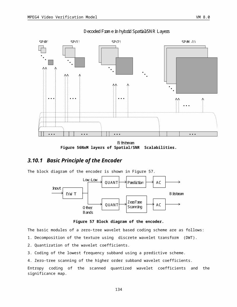
MPEG4 Video Verification Model VM 8.0
}
}
} while(nextbits_bytealigned()!=000 0000 0000 0000 0000 0000)
else {
if (video_object_layer_shape != “00”) {
do {
first_shape_code 1-3
}while(count of macroblocks!=total number of macroblocks)
}
if(error_resilience_disable) {
motion_coding()
if (video_object_layer_shape != “00”)
shape_coding()
texture_coding()
}
else
do{
do {
motion_coding()
} while (next_bits()!=‘1010 0000 0000 0000 1’)
motion_marker 17
if (video_object_layer_shape != “00”)
shape_coding()
do{
texture_coding()
} while (nextbits_bytealigned()!= ‘0000 0000 0000 0000’)
if(nextbits_bytealigned()!=000 0000 0000 0000 0000 0000) {
next_resync_marker()
resync_marker 17
macroblock_number 1-12
quant_scale 5
header_extension_code 1
if (header_extension_code == 1) {
do {
modulo_time_base 1
} while (modulo_time_base != 0 )
VOP_time_increment 1-15
134
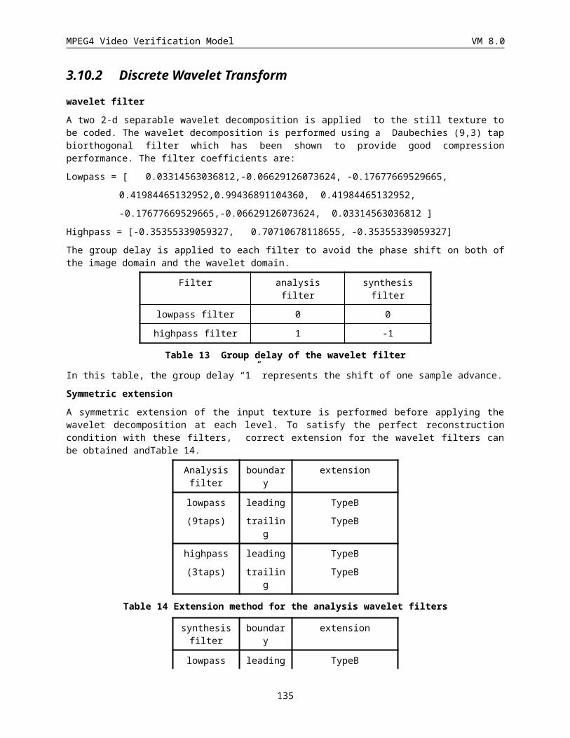
MPEG4 Video Verification Model VM 8.0
}
}
} while (nextbits_bytealigned() != 000 0000 0000 0000 0000 0000)
}
}
else {
if (enhancement_type) {
load_backward_shape 1
if (load_backward_shape) {
backward_shape_width 13
backward_shape_height 13
backward_shape_horizontal_mc_spatial_ref 13
marker_bit 1
backward_shape_vertical_mc_spatial_ref 13
backward_shape_coding()
load_forward_shape 1
if (load_forward_shape) {
forward_shape_width 13
forward_shape_height 13
forward_shape_horizontal_mc_spatial_ref 13
marker_bit 1
forward_shape_vertical_mc_spatial_ref 13
forward_shape_coding()
}
}
}
ref_select_code 2
if(VOP_prediction_type==“01”||VOP_prediction_type== “10”) {
forward_temporal_ref 1-15
if (VOP_prediction_type == “10”) {
marker_bit 1
backward_temporal_ref 1-15
}
}
combined_motion_shape_texture_coding()
}
do{
135
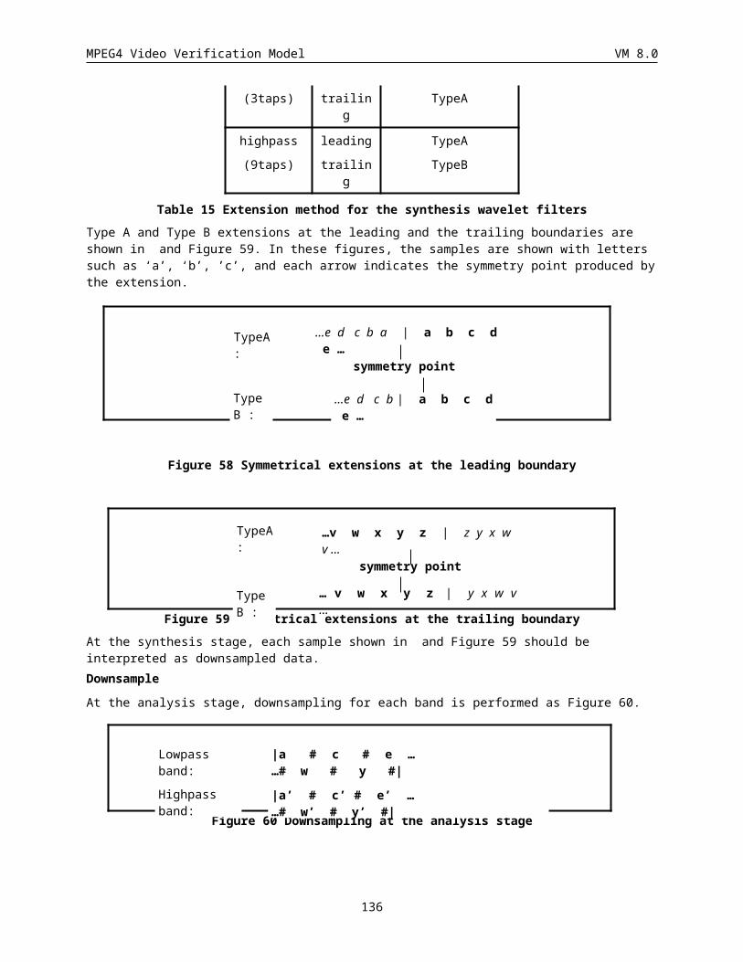
MPEG4 Video Verification Model VM 8.0
VideoObjectPlane()
}while(nextbits_bytealigned()==video_object_plane_start_code)
next_start_code()
}
VOP_start_code
This code cannot be emulated by any combination of other valid bits in the bitstream, and is used for synchronization purpose. It is sc followed by a unique 8-bit code.
modulo_time_base
This value represents the local time base at the one second resolution unit (1000 milliseconds). It is represented as a marker transmitted in the VOP header. The number of consecutive “1” followed by a “0” indicates the number of seconds has elapsed since the synchronisation point marked by the modulo_time_base of the last displayed I/P-VOPs belonging to the same VOL. There are two exceptions, one for the first I/P-VOP after the GOV header, and the other is for B-VOPs prior (in display order) to the first I-VOP after the GOV header.
For the first I/P-VOP after the GOV header, the modulo_time_base indicates the time relative to the time_code in the GOV header.
For the B-VOPs prior (in display order) to the first I-VOP after the GOV header, the modulo_time_base indicates the time relative to the time_code in the GOV header.
Note: When the bitstream contains B-VOPs, the decoder needs to store two time_base, one is indicated by the last displayed I/P-VOP or the GOV header and the other is indicated by the last decoded I/P-VOP.
VOP_time_increment
This value represents the absolute VOP_time_increment from the synchronization point marked by the modulo_time_base measured in the number of clock ticks. It can take a value in the range [0, VOP_time_increment_resolution). The number of bits representing this value is calculated as the minimum number of bits required to represent the above range. The local time base in units of seconds is recovered by dividing this value by the VOP_time_increment_resolution. For I/P and B-VOP this value is the absolute VOP_time_increment from the synchronisation point marked by the modulo_time_base.
136
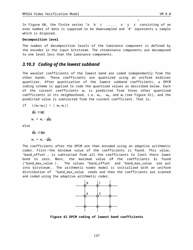
MPEG4 Video Verification Model VM 8.0
750
150
GOV
550
350
350
local time base
modulo_time_base
1000ms 1000ms
xx VOP_time_increment
BI PB B
0h:12m:34secTime code inGOV layer
0h:12m:35sec 0h:12m:36sec
“0” “0” “10” “10” “110”
“xx”
Note: The 1st VOP(B-VOP) in display order locates prior to the I-VOP, so its time_base refers to the time_code in the GOV header.
The 3rd VOP(B-VOP) locates in the time period 1 second distance from the modulo_time_base indicated by the 2 nd
VOP(I-VOP), so the modulo_time_base for the 3th VOP(B-VOP) shall be “10”.
The 4th VOP(B-VOP) refers to the 2nd VOP(I-VOP), the modulo_time_base for the 4th VOP(B-VOP) shall be “10”.
The 5th VOP(P-VOP) refers to the 2nd VOP(I-VOP), the modulo_time_base for the 5th VOP(P-VOP) shall be “110”.
137
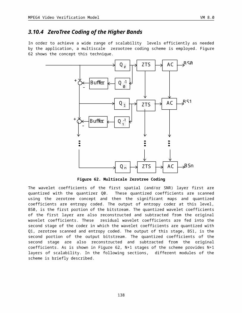
MPEG4 Video Verification Model VM 8.0
750
150
GOV
550
350
350
local time base
modulo_time_base
1000ms 1000ms
xx VOP_time_increment
BI PB B
0h:12m:34secTime code inGOV layer
0h:12m:35sec 0h:12m:36sec
“0” “0” “10” “0”
“xx”
“10”
Note: The 3rd VOP(I-VOP) in display order locates in the time period 1 second distance from the time_code in the GOV header, the modulo_time_base for the 3th VOP(I-VOP) shall be “10”. Since the 4th VOP(B-VOP) refers to the 3nd VOP(I-VOP), the modulo_time_base for the 4th VOP(B-VOP) shall be “0”.
To produce a picture at a given time (according to the display frame rate), the simplest solution is to use the most recently decoded data of each VOP to be displayed. Another possibility, more complex and for non real time applications, could be to interpolate each VOP from its two occurences temporally surrounding the needed instant, based on their temporal references.
vop_coded
This is a single bit flag which when equal to ‘0’ indicates that the VOP at this time instant has no further data. The VOP should not be displayed at this time instant. If this bit flag is ‘1’, ten decoding of the VOP header, shape and texture is continued.
VOP_prediction_type
This code indicates the prediction mode to be used for decoding the VOP as shown in below. All modes (unrestricted motion estimation, advanced prediction and overlapped motion compensation) are always enabled.
VOP prediction types
VOP_prediction_type Code
I 00
P 01
B 10
138
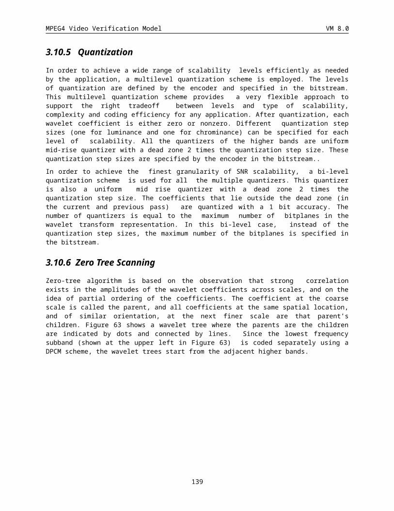
MPEG4 Video Verification Model VM 8.0
SPRITE 11
VOP_rounding_type
This single bit flag signals the value of the parameter rounding_control used for pixel value interpolation in motion compensation for P-VOPs (see sections 3.3.3.4 and 3.9.5.1.5). When this flag is set to ‘0’, the value of rounding_control is 0, and when this flag is set to ‘1’, the value of rounding_control is 1. When VOP_rounding_type is not present in the VOP header, the value of rounding_control is 0.
The encoder should control VOP_rounding_type so that each P-VOP have a different value for this bit from its reference picture for motion compensation. VOP_rounding_type can have an arbitrary value if the reference picture is an I-VOP. (However for core experiments and bitstream exchange, the value of VOP_rounding_type in the first P-VOP after an I-VOP shall be 0).
encode_sprite_trajectory()
According to the number of sprite points specified in number_of_sprite_points in the VideoObjectLayer Class, differential motion vectors of the sprite points are encoded in this field. When m sprite points are necessary to determine the transform, differential motion vectors (du[r], dv[r]) = (dur, dvr) (0 r < m) defined in section are transmitted.
Syntax No. of bits Mnemonic
encode_sprite_tragectory () {
for (i = 0; i < no_of_sprite_points; i++){
corner_mv_code(du[i] )
corner_mv_code(dv[i])
}
}
corner_mv_code(dmv)
The codeword for each differential motion parameter consists of VLC indicating the length of the dmv code (dmv_SSSS) and the dmv code itself (dmv_code). The codewords are listed in table dmv.
Syntax No. of bits Mnemonic
corner_mv_code (d) {
horizontal_dmv_SSSS 2-9 uimsbf
horizontal_dmv_code 0-11 uimsbf
}
dmv value SSSS VLC dmv code
-2047...-1024, 1024...2047
11 111111110 00000000000...01111111111, 10000000000...11111111111
-1023...-512, 10 11111110 0000000000...0111111111,
139
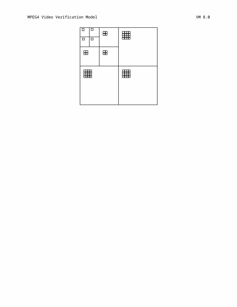
MPEG4 Video Verification Model VM 8.0
512...1024 1000000000...1111111111
-511...-256, 256...511 9 1111110 000000000...011111111, 100000000...111111111
-255...-128, 128...255 8 111110 00000000...01111111, 10000000...11111111
-127...-64, 64...127 7 11110 0000000...0111111, 1000000...1111111
-63...-32, 32...63 6 1110 000000...011111, 100000...111111
-31...-16, 16...31 5 110 00000...01111, 10000...1111
-15...-8, 8...15 4 101 0000...0111, 1000...1111
-7...-4, 4...7 3 100 000...011, 100...111
-3...-2, 2...3 2 011 00...01, 10...11
-1, 1 1 010 0, 1
0 0 00 -
Table 20 Code table for the first trajectory point
lighting_change_factor_encode ()
For simplicity and as a start to support this effect, constant lighting change is used. That is, the lighting change factor is the same for all pixels in a VOP. The final warped pixel value P of pixel ( i, j) is equal to Pij = L * Pijb where Pijb is the warped pixel value after bi-linear interpolation (see Section ) and L is the lighting change factor.
The following method is used to code the lighting change factor.
· The accuracy is the second digit after the decimal point, i.e., x0.01.
· The quantized value is clapped to the range of [0, 17.5].
· Subtract L by 1 and code the result multiplied by 100. In other words, code 1000 * Ls where Ls = L - 1.
· Use the Table below to code Ls:
value VLC code total number of bits
-16...-1, 1...16 0 00000...01111, 10000...11111 6
-48...-17, 17...48 10 000000...011111, 100000...111111 8
112...-49, 49...112 110 0000000...0111111, 1000000...1111111 10
113…624 1110 000000000...111111111 13
625...1648 1111 0000000000…1111111111 14
Table 21 Code table for scaled lighting change factor
blending_factor
This 8-bit field defines the blending parameter used in the on-line sprite generation. The blending parameter has value between [0,1] and is obtained by dividing blending_factor by 254.
sprite_transmit_mode
This flag selects the transmission mode of the sprite object. The flag is set to PIECE if an object piece is being sent. When an update piece is being sent, this flag is set to UPDATE. When all the sprite object pieces and quality update pieces for the current VOP are sent, the flag is set to PAUSE. Note that this does not signal the end of all transmission of object and quality update pieces for the entire VOL, but only for the current VOP. When all
140
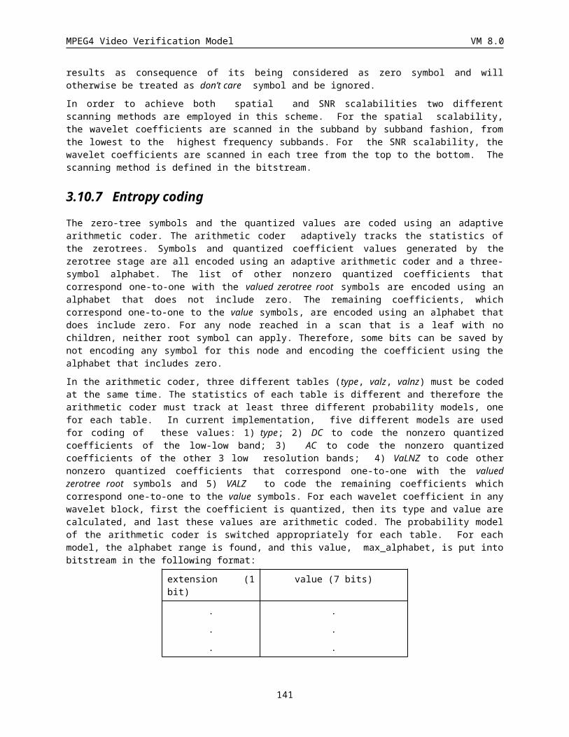
MPEG4 Video Verification Model VM 8.0
the object and quality update pieces (PIECE or UPDATE) for the entire VOL have been sent and no additional transmission of sprite pieces is required, this flag is set to STOP. Note that this flag is set to PIECE at VOL initialization.
sprite_transmit_mode
sprite_transmit_mode Code
STOP 00
PIECE 01
UPDATE 10
PAUSE 11
checkSpriteTransMode ()
This function determines how the sprite object should be parceled to meet both the timing and bit rate considerations. Depending on the action of the camera (zooming, panning, etc...), the transmission order of the object pieces is determined. For example, if the sequence is showing a zooming out effect, then regions on all four sides of the transmitted piece(s) will be exposed simultaneously at the next frame. This will require the transmission of pieces to the left, right, top, and bottom of the transmitted region. However, if the sequence is showing a panning effect, then only region on one side of the transmitted piece(s) will be exposed. In this case, pieces in the direction of the pan will be transmitted before those on the opposite side are transmitted. This function also determines when transmission of update pieces is appropiate. If simplicity is desired, one can transmit all object pieces before any update pieces are sent.
This function also keeps track of the quality of the transmitted sprite object pieces to determine if quality update pieces need to be sent. The quality metric can be the SNR calculated as follows:
SNR = 10 * log 10 (255 * 255 / MSE)
MSE = (N (Oi - Ri)2) / N - ((N (Oi - Ri)) / N) 2
Oi = i-th pixel value of original sprite object piece
Ri = i-th pixel value of reconstruct sprite object piece
N = number of pixels in sprite object piece
The quality of each piece is then compared to the desired SNR. When the quality of a piece falls below the desired SNR, it is marked for residual transmission. During this phase, the lowest quantizer stepsize that still satisfies the bit rate requirements is used. This is repeated for all the pieces until all the pieces have the desired SNR.
encodeSpritePiece ()
See description under Video Object Layer.
VOP_width, VOP_height
These two numerical values define the size of the ‘VOP formation’ rectangle, in pixel unit (zero value is forbidden for both VOP_height and VOP_width)
VOP_horizontal_mc_spatial_ref, VOP_vertical_mc_spatial_ref
These values are used for decoding and for picture composition. They indicate the spatial position of the top left of the rectangle defined by VOP_width and VOP_height, in pixels unit. The first bit is the sign bit (0= positive, 1=negative), followed by the natural binary representation of the position.
marker_bit
This is a single bit always set to '1' in order to avoid start code emulation.
141
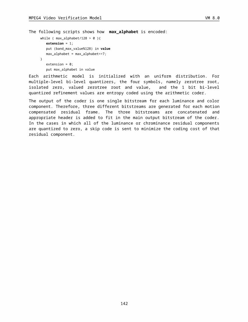
MPEG4 Video Verification Model VM 8.0
background_composition
This flag only occurs when scalability flag has a value of “1”. The default value of this flag is “1”. This flag is used in conjunction with enhancement_type flag. If enhancement_type is “1” and this flag is “1”, background composition specified in is performed. If enhancement type is “1” and this flag is “0”, any method can be used to make a background for the enhancement layer. Further, if enhancement type is “0” no action needs to be taken as a consequence of any value of this flag.
shape_coding()
The shape_coding() function generates the format of the coded data of a current shape (alpha plane).
The reference shape data for inter shape coding in an enhancement layer does not exist when the base layer is the reference and it is coded with video_object_layer_shape being “00.” In this case, the reference shape for the current shape coding is defined as a binary rectangle of the size of the entire image.
VOP_CR
This is a single bit that indicates the value for VOP level size conversion: 0 indicates that the VOP_CR is regarded as ‘1’, 1 indicates that the VOP_CR is regarded as ½.
Change_CR_disable
‘1’ indicates that the macroblock layer CR is not coded and it is regarded as 1. ‘0’ indicates that the macroblock layer CR is coded.
load_backward_shape
If this flag is “1”, backward_shape of the previous VOP is copied to forward_shape for the current VOP and backward_shape for the current VOP is decoded from the bitstream. If not, forward_shape for the previous VOP is copied to forward_shape for the current VOP and backward_shape for the previous VOP is copied to backward_shape for the current VOP.
backward_shape_coding()
It specifies the format of coded data for backward_shape and is identical to that of shape_coding().
load_forward_shape
This flag is “1” if forward_shape will be decoded from a bitstream.
forward_shape_coding()
It specifies the format of coded data for forward_shape and is identical to that of shape_coding().
backward_shape_width, backward_shape_height
These two numerical values define the size of the bounding rectangle that includes the backward_shape, in pixels unit (zero values are forbidden).
backward_shape_horizontal_mc_spatial_ref, backward_shape_vertical_mc_spatial_ref
These values indicate the spatial position of the top left of the rectangle defined by backward_shape_width and backward_shape_height, in pixels unit. The first bit is the sign bit (0= positive, 1=negative), followed by the natural binary representation of the position.
forward_shape_width, forward_shape_height
These two numerical values define the size of the bounding rectangle that includes the forward_shape, in pixels unit (zero values are forbidden).
forward_shape_horizontal_mc_spatial_ref, forward_shape_vertical_mc_spatial_ref
142
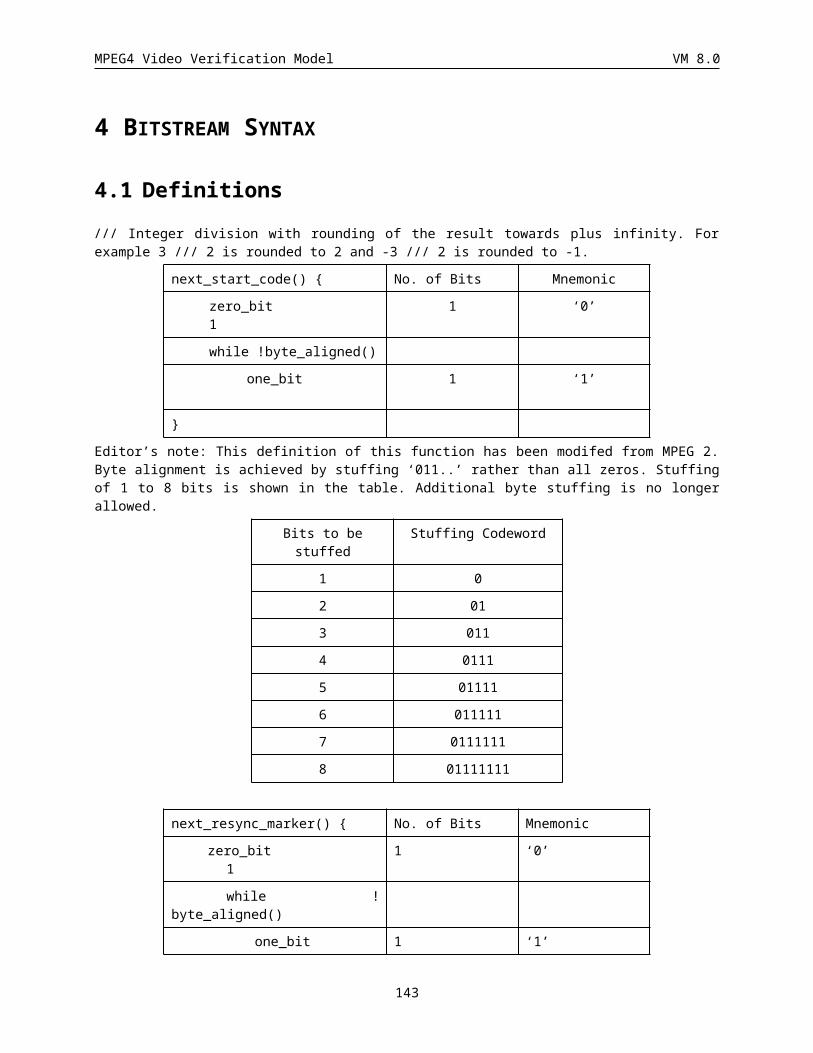
MPEG4 Video Verification Model VM 8.0
These values indicate the spatial position of the top left of the rectangle defined by forward_shape_width and forward_shape_height, in pixels unit. The first bit is the sign bit (0= positive, 1=negative), followed by the natural binary representation of the position.
marker_bit
This is a single bit always set to '1' in order to avoid start code emulation.
ref_select_code
This is a 2-bit code which indicates prediction reference choices for P- and B-VOPs in the enhancement layer with respect to decoded reference layer identified by ref_layer_id.
forward_temporal_ref
An unsigned integer value which indicates temporal reference of the decoded reference layer VOP to be used for forward prediction (Table 41 and Table 42)
backward_temporal_ref
An unsigned integer value which indicates temporal reference of the decoded reference layer VOP to be used for backward prediction (Table 42).
video_object_plane_fcode_forward, video_object_plane_fcode_backward
These are 3-bit codes that specify the dynamic range of motion vectors.
interlaced
This bit has the value '1' if the interlaced video coding tools are being used.
top_field_first
This bit is '1' if the top line of the video frame is part of the temporally first video field of the frame.
VOP_dbquant
VOP_dbquant is present if VOP_prediction_type indicates VOP_prediction_type==‘10’. dquant ranges from 1 to 31. VOP_dbquant is a 2-bit fixed length code that indicates the relationship between quant and bquant. Depending on the value of VOP_dbquant, bquant is calculated according to the relationship shown in Table 22 and is clipped to lie in the range 1 to 31. In this table “/” means truncation..
dbquant bquant
00 (5xquant)/4
01 (6xquant)/4
10 (7xquant)/4
11 (8xquant)/4
Table 22 VOP_dbquant codes and relation between quant and bquant
VOP_quant
A fixed length codeword of 5 bits which indicates the quantizer to be used for VOP until updated by any subsequent value DQUANT. The codewords are natural binary representations of the value of quantization which being half the step sizes range from 1 to 31.
VOP_gray_quant
143
MPEG4 Video Verification Model VM 8.0
A 6-bit fixed length codeword indicating the quantizer for quantizing gray-scale alpha masks. The codeword is a natural binary representation of the value of quantization. It is updated by any subsequent value of GDQUANT define below :
int R = (2 * VOP_gray_quant) // VOP_quant
int GDQUANT = (DQUANT * R) / 2
The quantizer updated by GDQUANT is allowed to exceed 63. It is not updated by GDQUANT when disable_gray_quant_update is set to "1". The quantizer for gray-scale alpha mask in a B-VOP is calculated by using VOP_dbquant in the same manner as the texture. The quantizer value is allowed to exceed 63.
first_shape_code
Each shape block is classified into seven classes as follows in accordance with the coding results of shape information, and these modes are coded using first_shape_code.
Shape_mode = “MVDs==0 && No Update”
Shape_mode = “MVDs!=0 && No Update”
Shape_mode = “all_0”
Shape_mode = “all_255”
Shape_mode = “intraCAE”
Shape_mode = “interCAE && MVDs==0”
Shape_mode = “interCAE && MVDs!=0”
1. I-VOP
Suppose that f(x,y) means Shape_mode described above of the VOP spatial position (x,y). The cord word for first_shape_code of the position (i,j) is determined as follows.
Index l is calculated from the already coded first_shape_code.
l = 27*(f(i-1,j-1)-3) + 9*(f(i,j-1)-3) + 3*(f(i+1,j-1)-3) + (f(i-1,j)-3)
If the position (x,y) is out of VOP, Shape_mode is assumed to be “all_0” (i.e. f(x,y)=3).
The code word is determined fromTable 23.
Index (3) (4) (5) Index (3) (4) (5)
0 0 11 10 41 11 10 0
1 11 10 0 42 0 10 11
2 10 11 0 43 11 0 10
3 0 11 10 44 11 10 0
4 0 10 11 45 0 10 11
5 0 10 11 46 11 10 0
6 0 11 10 47 10 11 0
7 0 10 11 48 0 10 11
8 10 11 0 49 11 10 0
9 11 10 0 50 10 11 0
10 0 10 11 51 0 11 10
11 0 10 11 52 11 0 10
144
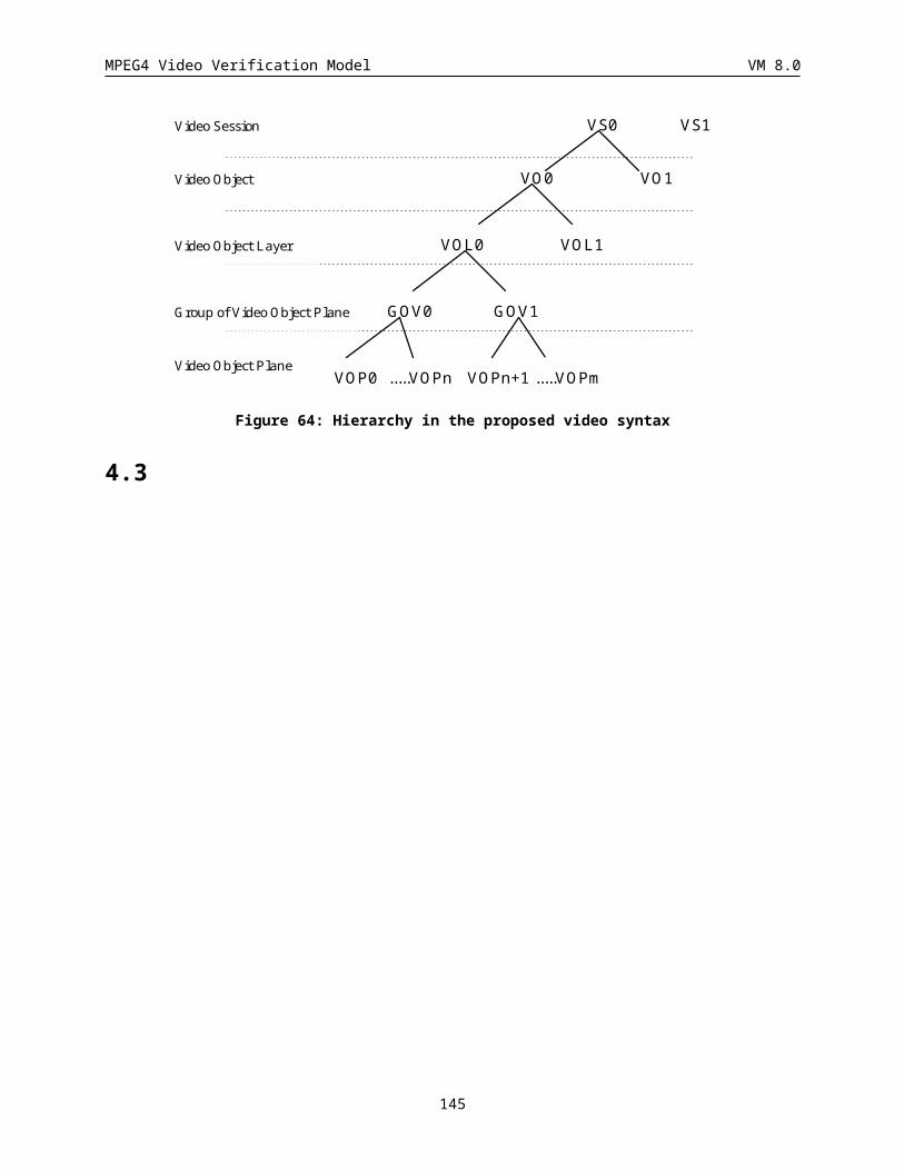
MPEG4 Video Verification Model VM 8.0
12 11 10 0 53 10 11 0
13 0 10 11 54 0 11 10
14 10 0 11 55 10 11 0
15 11 10 0 56 10 11 0
16 0 10 11 57 0 10 11
17 0 10 11 58 0 10 11
18 10 11 0 59 0 10 11
19 0 10 11 60 0 10 11
20 11 10 0 61 0 10 11
21 10 11 0 62 10 11 0
22 0 10 11 63 0 10 11
23 11 10 0 64 11 10 0
24 10 11 0 65 11 10 0
25 11 10 0 66 10 11 0
26 11 10 0 67 11 0 10
27 0 10 11 68 11 0 10
28 0 10 11 69 10 11 0
29 0 10 11 70 11 0 10
30 0 10 11 71 11 10 0
31 0 10 11 72 0 11 10
32 0 10 11 73 11 10 0
33 0 10 11 74 10 11 0
34 0 10 11 75 10 11 0
35 11 10 0 76 11 0 10
36 0 10 11 77 11 10 0
37 11 10 0 78 0 11 10
38 11 10 0 79 11 0 10
39 0 10 11 80 11 10 0
40 11 0 10
Table 23 first_shape_code for I-VOP
1. P or B-VOP
first_shape_code is determined according to the Shape_mode of a current VOP and that of the same position in a previous VOP as follow:
Shape_mode in current VOP (n)
(1) (2) (3) (4) (5) (6) (7)
145
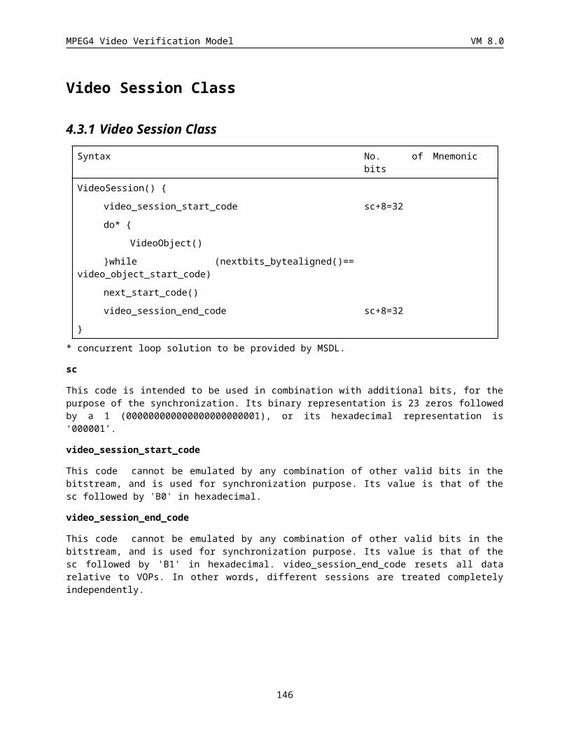
MPEG4 Video Verification Model VM 8.0
Shape_mode in current VOP (n)
(1) 1 01 00010 00011 0000 0010 0011
Shape_mode (2) 01 1 00001 000001 001 000000 0001
in previous (3) 0001 001 1 000001 01 000000 00001
VOP(n-1) (4) 1 0001 000001 001 01 000000 00001
(5) 100 101 1110 11110 0 11111 110
(6) 10 1110 11110 11111 110 00 01
(7) 110 1110 11110 11111 10 01 00
Note : (1)-(7) in the table mean the seven classes of first_shape_code described above
Table 24 first_shape_code for P-VOP
If the size of current VOP is different from that of previous VOP, the following disposition is carried out.
The line (column) of the previous VOP is longer than that of the current VOP, right side column (bottom line) is eliminated.
The line (column) of the previous VOP is shorter than that of the current VOP, right side column (bottom line) is repeated.
Example is shown in Figure FirstCode. In this figure, each number means as follows:
0 : MVDs = 0 && No Update
1 : MVDs=0 && interCAE
2 : intraCAE
3 : all_0
Suppose that a size of the previous VOP (Figure 65 (a) : Time is “n-1”) is converted to a size of the current VOP (Figure 65 (d) : Time is “n”). First, the right side column is cut (Figure 65 (b)), and after that, the bottom line is copied (Figure 65 (c)).
2 112 21 22 012 21 22 011 10 22 011 10 22 001 00 13 030 00 30 000 30 1
2 112 212 012 212 011 102 011 102 001 003 030 000 000 30
2 112 222 012 212 011 112 011 101 001 003 003 000 000 000 000 00
2 112 212 012 212 011 102 011 102 001 003 030 000 000 300 000 30
(a) (b) (c)
(d)
n-1
n
cutcopy
146
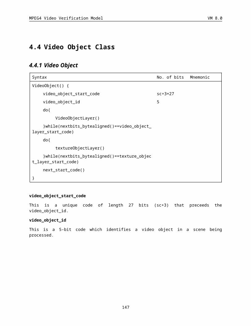
MPEG4 Video Verification Model VM 8.0
Figure 65: example of size fitting between current VOP and previous VOP
resync_marker
These bits always take the value 0 0000 0000 0000 0001. They are only present when error_resilient_disable_flag has value 0.
Editor’s note:
In error resilient mode, the function combined_motion_shape_texture_coding() will return to the VideoObjectPlane layer after every macroblock.
In error resilient mode, the functions motion _coding(), shape_coding(), texture_coding() will also return to the VideoObjectPlane layer after every macroblock.
macro_block_number
The number of a macroblock within a VOP. This field has value zero for the top left macroblock. The macroblock number increases moving first to the left, and then down, the VOP. This field is only present when error_resilient_disable_flag has value 0.
The length of this field is determined from the table below.
(VOP_width /// 16) * (VOP_height /// 16) Length of macro_block_number
1-2 1
3 - 4 2
5 - 8 3
9 - 16 4
17 - 32 5
33 - 64 6
65 - 128 7
129 - 256 8
257 - 512 9
513 - 1024 10
1025 - 2048 11
2049 - 4096 12
quant_scale
This field contains the value of the quantisation scale parameter.
header_extension_code
The header_extension_code (HEC) is a one bit flag which indicates whether or not additonal information is available in the resynchronization header.
header_extension_code = 0: No addditional information.
header_extension_code = 1: The additional information follows the HEC.
motion_marker
This is a 17 bit field which always takes the value ‘1010 0000 0000 0000 1’. It is only present when the error_resilient_disable_flag has a value ‘0’.
147
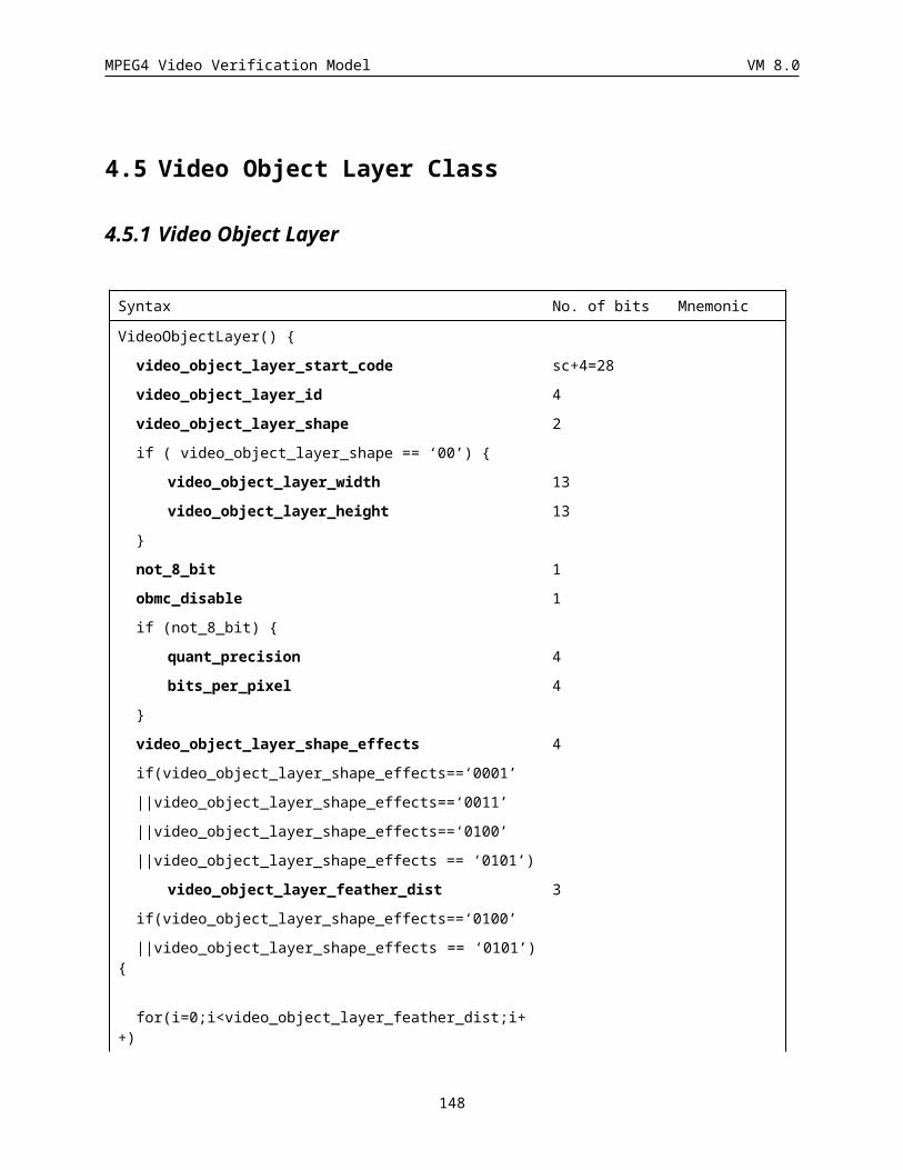
MPEG4 Video Verification Model VM 8.0
VOP_constant_alpha
This 1-bit code selects whether the Constant Alpha effect on or off. When the Constant Alpha effect is on, the opaque alpha values in the binary mask are replaced with the alpha value specified by VOP_constant_alpha_value. When the Constant Alpha effect is off, the alpha mask is encoded by the default grayscale coding algorithm.
VOP_constant_alpha_value
This is an 8-bit code that gives the alpha value to replace the opaque pixels in the binary alpha mask with when using the Constant Alpha effect.
Complexity parameters
DCECS_intra: intra type macroblock counting
DCECS_intra_Q: intra + Q type macroblock countingDCECS_Not_coded: not-coded type macroblock countingDCECS_inter: inter type macroblock counting DCECS_inter4v: inter 4v type macroblock counting
DCECS_inter_Q: inter + Q type macroblock countingDCECS_interpolate: interpolate type macroblock countingDCECS_forward: forward prediction type macroblock counting DCECS_backward: backward prediction type macroblock countingDCECS_direct_h263: H.263 direct type macroblock countingDCECS_zig_zag_DCT: statistic of DCT coefficients
DCECS_half_pel_ap: half pel advanced prediction vector counting
DCECS_ half_pel_np: half pel normal prediction vector counting
DCECS_ VLC_symbol: statistic of VLD operations
DCECS_shape ……t.b.d …….. tbd
DCECS_ sprite ……t.b.d …….. tbd
4.8 Shape codingbinary shape coding
Syntax No. of bits Mnemonic
binary_shape_coding() {
if (video_object_layer_shape != '00') {
do {
if (Shape_mode = “MVDs!=0 && NotCoded” ||
Shape_mode=”interCAE && MVDs!=0”)
MVDs 3-36
if (Shape_mode = ”intraCAE”
|| Shape_mode=”interCAE && MVDs==0”
148
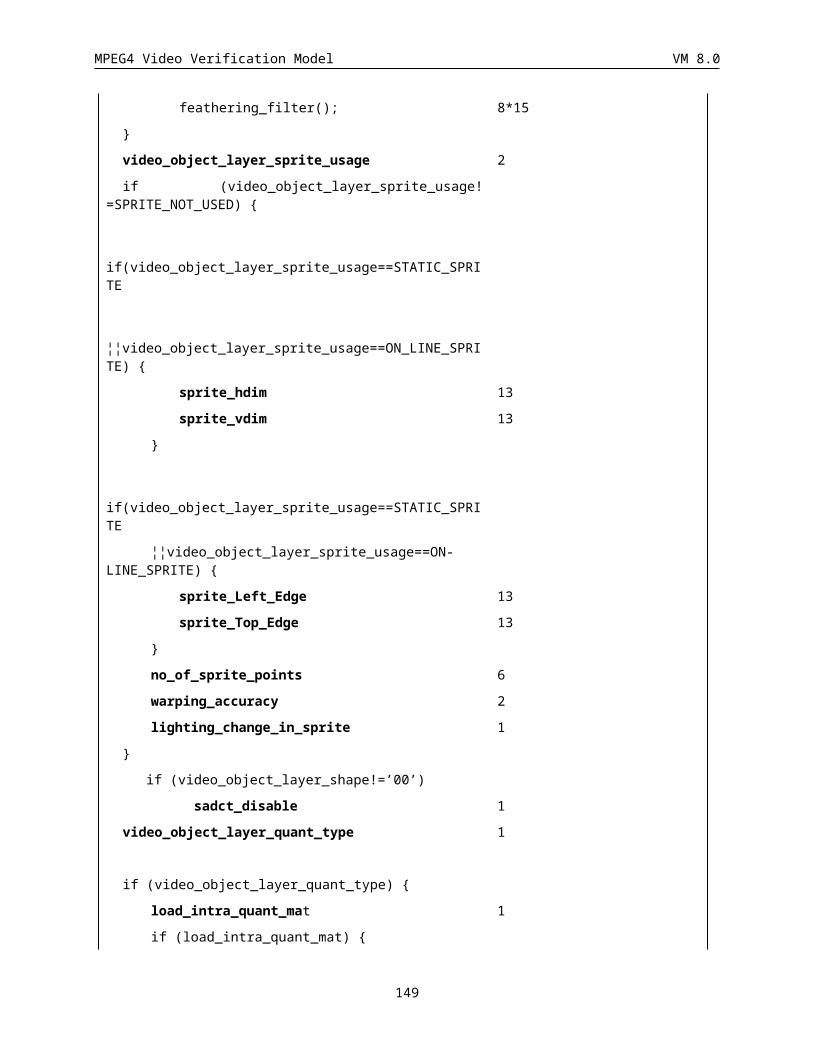
MPEG4 Video Verification Model VM 8.0
|| Shape_mode=”interCAE && MVDs!=0” ) {
if (change_CR_disable==”0”)
CR 1-2
ST 1
BAC
}
}while(count of macroblock != total number of macroblocks)
}
MVDs
Differential MV for shape information.
MVDs is coded in the following two cases.
(1) Shape_mode= “MVDs !=0 && NotCoded”
(2) Shape_mode= “interCAE && MVDs!=0”
MVDs is coded in horizontal element and vertical element order using Table 25.
Only in the case that horizontal element is 0, Table 26 is used for Vertical element. This table is got by subtracting the first one bit from codewords in Table 25. (Since MVDs is not 0, vertical element is not 0 even if horizontal element is 0.)
MVDs Codes
0 1
1 01s
2 001s
3 0001s
4 00001s
5 000001s
6 0000001s
7 00000001s
8 000000001s
9 0000000001s
10 00000000001s
11 000000000001s
12 0000000000001s
13 00000000000001s
14 000000000000001s
15 0000000000000001s
149
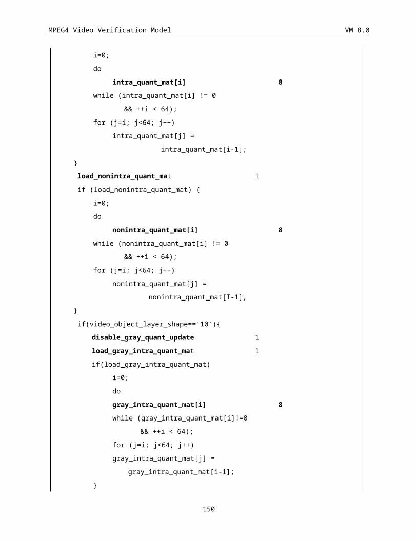
MPEG4 Video Verification Model VM 8.0
16 00000000000000001s
Table 25 VLC table for MVDs
MVDs Codes
1 1s
2 01s
3 001s
4 0001s
5 00001s
6 000001s
7 0000001s
8 00000001s
9 000000001s
10 0000000001s
11 00000000001s
12 000000000001s
13 0000000000001s
14 00000000000001s
15 000000000000001s
16 0000000000000001s
s: sign bit (if MVDs is positive s=”1”, otherwise s=”0”).
Table 26 VLC table for MVDs (Horizontal element is 0)
CR
Conversion ratio for Binary Alpha Block. The codeword table is shown in Table27Table 27 VLC for CRss. It is not appears when change_CR_disable= “1”.
CR Code
1 0
1/2 10
1/4 11
Table 27 VLC for CR
ST
Scan order. The codeword for Horizontal scan (ST=1)/ Vertical scan (ST=0).
150
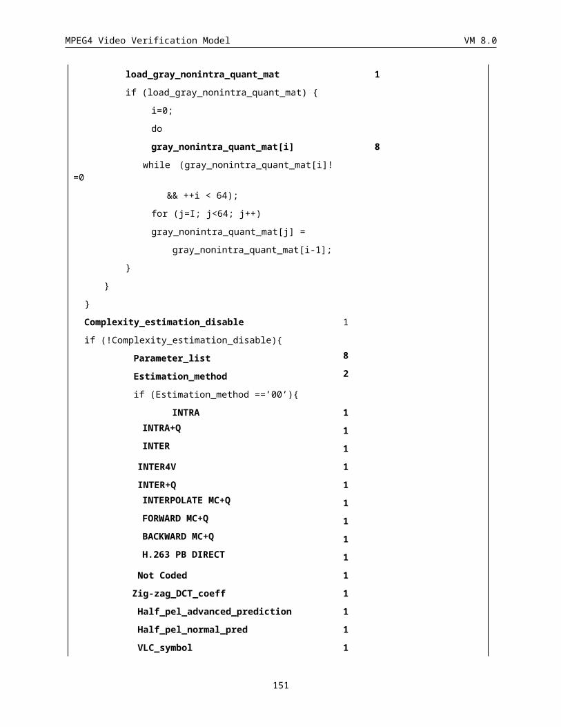
MPEG4 Video Verification Model VM 8.0
4.9 Motion Shape Texture
4.9.1 Combined Motion Shape Texture The motion shape texture coding method used for I-, P- and B-VOPs is described in section (Appendix A). The advanced prediction mode and overlapping motion estimation are also described in that Appendix. The macroblock layer syntax for each coded macroblock consists of macroblock header information which also includes motion vectors, and, block data which consists of DCT data (coded texture information).
Note: When the Error_Resilient_Disable flag is disabled and Reversible_VLC flag is enabled, the DCT Data should be encoded using the reversible VLC table given in Appendix B. However, this does not require the remultiplexing of the texture data. When reversible decoding is required, the Combined Motion Texture Coding Mode can be remultiplex with a reynchronization packet to allow this. This remultiplexing method is provided in Section 6.3
4.9.2 Separate Motion Shape Texture Syntax for I-, P-, and B-VOPs
4.9.2.1 I-VOPsFor each I-VOP, the Separate syntax consists of first_shape_codes for all macroblocks in the VOP's bounding box, followed by Shape and Texture data. The details of the syntax components are provided in the following.
first_shape_code
For each macroblock in the I-VOP the first_shape_code is first sent:
1-2 bits
first_shape_code
Binary shape coding
For each macroblock in the I-VOP, the binary shape data consists of
1-2 bits 1 bits
CR ST BAC
All data are coded as in the Combined Motion Shape Texture case.
Gray scale shape coding
For each macroblock in the I-VOP, the gray scale shape data consists of
1 bits 1 bit 1-6 bits N bits
CODA Aacpred_flag CBPA Alpha data
All data are coded as in the Combined Motion Shape Texture case.
Texture coding
the motion coding part of the syntax is skipped. Also, in the texture coding part the NO_DCT flag is skipped too. Hence for each macroblock in the I-VOP the texture data only consists of:
1-9 bits 1 bit 1-6 bits 2 bits 1-bit N bits
MCBPC ACpred_flag CBPY DQUANT dct_type DCT data
151
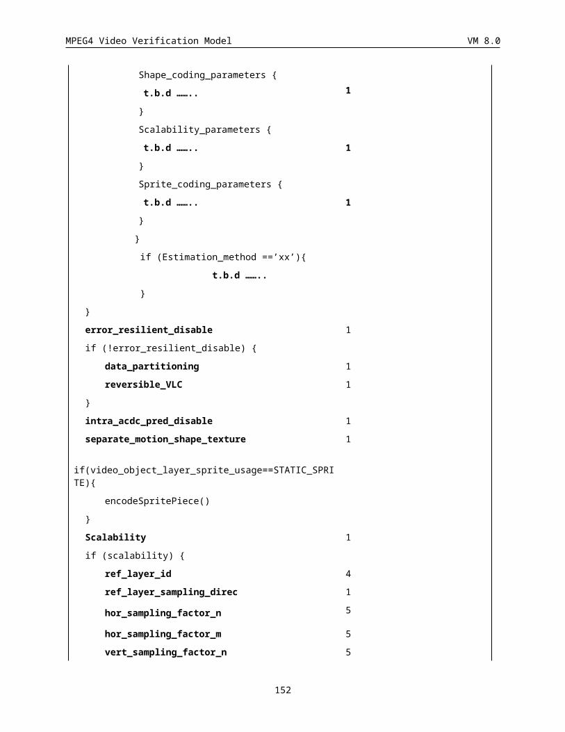
MPEG4 Video Verification Model VM 8.0
MCBPC: Mode and Coded Block Pattern Chrominance gives information on i) whether DQUANT is present or not, and ii) coded block pattern for chrominance. The Huffman table for the MCBPC is the same as the one for the P-VOP case given in the next section (see Table 30).
ACpred_flag: Is defined similar to that in section .
Aacpred_flag: Is defined similar to that in section .
CBPY: Coded Block Pattern for luminance (Y) specifies those Y non transparent blocks in the macroblock for which at least one non-INTRADC transform coefficient is transmitted. The coding of CBPY is similar to that of combined mode.
DQUANT: define changes in the value of the VOP_quantizer. The DQUANT values and respective codes are the same as the ones used for the P-VOP case given in the next section (see Table 32).
dct_type: this bit is only present if interlaced is ‘1’. When present, dct_type is ‘1’ to denote the use of the field DCT re-ordering of the lines of the macroblock as specified in section
DCT data: DCT encoded macroblock data consists of four luminance and two chrominance difference blocks. The same Block Layer structure used in the Combined case is adopted here (see Sec. ).
4.9.2.2 P-VOPsFor each P-VOP, the Separate syntax consists of first_shape_codes for all macroblocks in the VOP's bounding box, followed by Motion, Shape, and Texture data. The details of the syntax components are provided in the following.
first_shape_code
For each macroblock in the VOP’s bounding box first_shape_code is provided.
1-7 bits
first_shape_code
Binary shape_coding
For each macroblock in the P-VOP the binary shape data consists of:
N bits 1-2 bits 1 bits
MVDs CR ST BAC
All the above data are coded as in the Combined Motion Shape Texture case.
Motion_coding
The syntax for the motion information related to all macroblocks that belong to the VOP would be:
1-2 bits N bits 1-2 bits N bits
No. of Vectors Encoded vectors ...
No. of Vectors Encoded vectors ...
..........
No. of Vectors: Huffman coded number of motion vectors for each macroblock (0, 1, or 4).
A `0’ indicates that there is no motion compensation for macroblock. Hence the data coded by the texture coding part will be the actual pixel values in the current image at this macroblock location (INTRA coded) or skipped by the texture coding syntax. A ‘1’ indicates that this macroblock is motion compensated by a 16 x 16 motion vector. Similarly a ‘4’ indicates that this macroblock is motion compensated by 4, 8 x 8 motion vectors.
The Huffman codes used to code this No. of Vectors field are presented in Table 28.
Value Interlaced Length Code
0 0 or 1 2 11
152
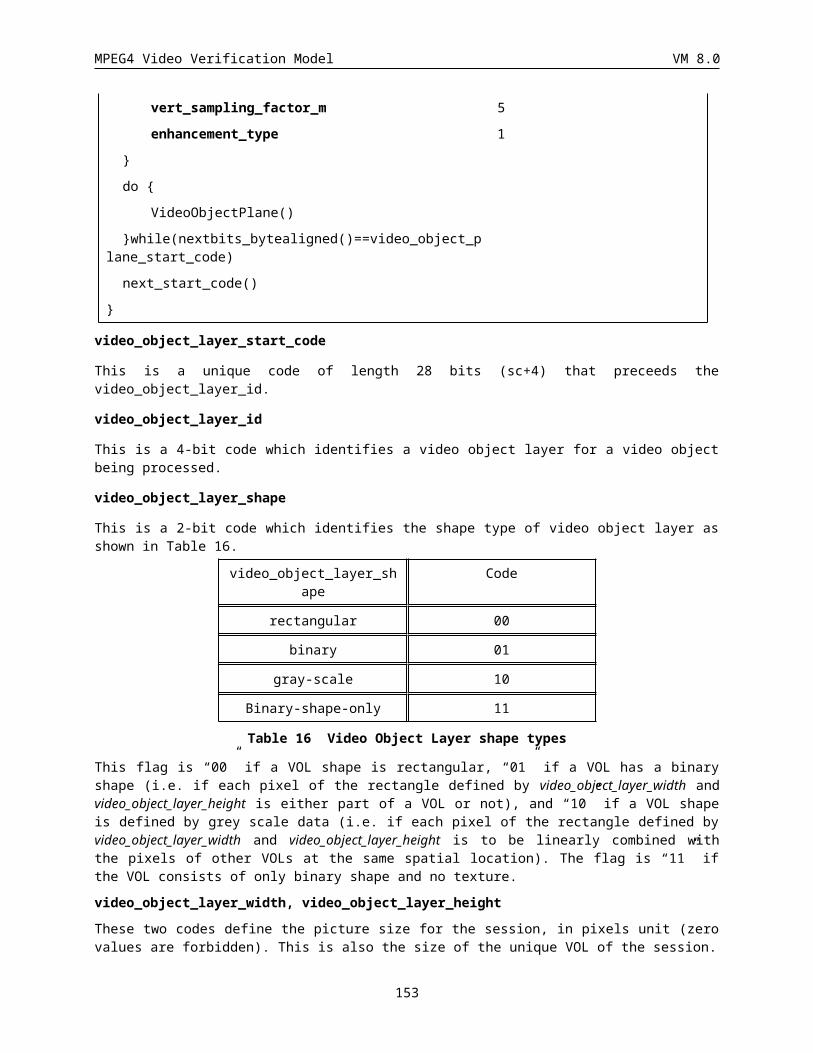
MPEG4 Video Verification Model VM 8.0
1 0 1 0
1 1 2 00
2 1 4 01tb
4 0 or 1 2 10
Table 28 VLC table for No. of Vectors.
The ‘t’ and ‘b’ bits in 2 vector case (field motion compensation) in table above specifies the reference fields for top and bottom field motion vectors respectively. A value of ‘0’ denotes a reference to the top field and ‘1’ specifies a reference to the bottom field.
Encoded vectors: these are differentially coded using the same prediction scheme and Huffman tables, as described in sections., , and ,
Gray scale shape_coding
For each macroblock in the P-VOP the gray scale shape data consists of:1-2 bits 1 bit 1-6 bits N bits
CODA Aacpred_flag CBPA Alpha data
CODA, CBPA and alpha data are coded similar to those of combined motion shape texture case.
Texture_coding (when error resilience is disabled)
The texture data for the macroblocks belonging to the VOP is coded using a DCT coding as in Combined Motion Shape Texture case. The syntax of the texture coding for each of the macroblocks in the VOP is as follows:
1 bits 1-9 bits 1 bit 1-6 bits 2 bits 1 bit N bits
NO_DCT flag MCBPC ACpred_flag CBPY DQUANT dct_type DCT data
NO_DCT flag: this flag indicates whether a macroblock has DCT data or not. If it has no DCT data it is set to ‘1’, otherwise it is set to ‘0’. The Huffman Codes used to code the NO_DCT flag are reported in Table 29.
Value Length Code
0 1 0
1 1 1
Table 29 NO_DCT values and codes.
To skip a macroblock, No. of Motion Vectors is set to ‘0’ (i.e. Code = ‘11’) and the NO_DCT flag to ‘1’ (i.e. Code = ‘1’).
MCBPC: Mode and Coded Block Pattern Chrominance gives information on i) whether DQUANT is present or not, and ii) coded block pattern for chrominance. The Huffman table for the MCBPC is provided in Table 30.
Value DQUANT CBPC (56) Length Code
0 -- 00 1 1
1 -- 01 3 001
2 -- 10 3 010
3 -- 11 3 011
4 x 00 4 0001
5 x 01 6 0000 01
153
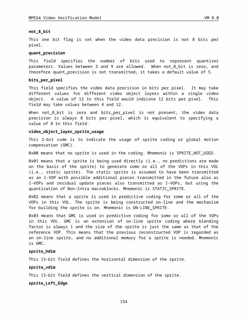
MPEG4 Video Verification Model VM 8.0
6 x 10 6 0000 10
7 x 11 6 0000 11
8 stuffing -- 9 0000 0000 1
Table 30 VLC table for the MCBPC for I- and P-VOPs, where “x” means that DQUANT is present.
CBPY: Coded Block Pattern for luminance (Y) specifies those Y blocks in the macroblock for which at least one non-INTRADC transform coefficient is transmitted. The Huffman table for the CBPY is the same as the one used for the Combined Motion Shape Texture coding method (see Sec. ) and presented in Table 31.
Value CBPY(I)
(1234)
CBPY(P)
(1234)
CBPY(SPRITE)
(1234)
Length Code
0 00
00
11
11
11
11
4 0011
1 00
01
11
10
11
10
5 0010 1
2 00
10
11
01
11
01
5 0010 0
3 00
11
11
00
11
00
4 1001
4
01
00
10
11
10
11
5 0001 1
5 01
01
10
10
10
10
4 0111
6 01
10
10
01
10
01
6 0000 10
7 01
11
10
00
10
00
4 1011
8 10
00
01
11
01
11
5 0001 0
9 10
01
01
10
01
10
6 0000 11
10 10
10
01
01
01
01
4 0101
11 10
11
01
00
01
00
4 1010
12 11 00 00 4 0100
154
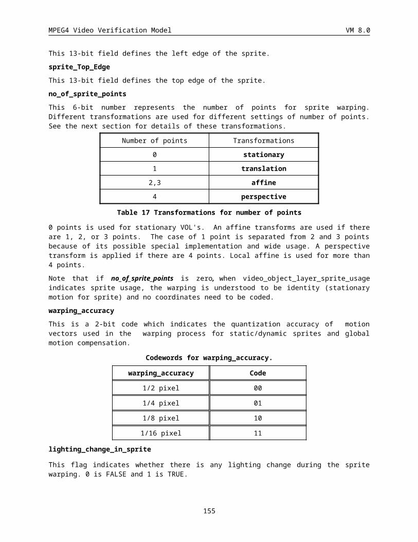
MPEG4 Video Verification Model VM 8.0
00 11 11
13 11
01
00
10
00
10
4 1000
14 11
10
00
01
00
01
4 0110
15 11
11
00
00
00
00
2 11
Table 31 VLC table for CBPY for I-, P- and Sprite-VOPs.
DQUANT: define changes in the value of the VOP quantizer. The DQUANT values and respective codes are the same used in the Combined Motion Shape Texture and presented in Table 32.
Value DQUANT Differential Value
Code
0 -1 00
1 -2 01
2 1 10
3 2 11
Table 32 DQUANT differential values and codes for I-, P- and Sprite- VOPs.
dct_type:ia present only when the interlaced flag is “ON” (‘1’). If dct_type is ‘1’, the field DCT ordering of the lines is the macroblock is used as specified in section .
DCT data: DCT encoded macroblock data consists of four luminance and two chrominance difference blocks. The same Block Layer structure used in the Combined case is adopted here (see Sec. ).
Macroblock types and included elements for I- and P-VOPs are listed in Table 33.
VOP MB type NO_DCT CBPY MCBPC DCT data
DQUANT No. of Vectors
I INTRA -- x x x -- --
I INTRA+Q -- x x x x --
P N.C. x -- -- -- -- x
P INTER x x x x -- x
P INTER+Q x x x x x x
P INTER4V x x x x -- x
P INTER4V+Q x x x x x x
P INTRA x x x x -- x
P INTRA+Q x x x x x x
Table 33 Macroblock types and included elements for I- and P-VOPs.
155
MPEG4 Video Verification Model VM 8.0
4.9.2.3 B-VOPsFor each B-VOP, the Separate syntax consists of first_shape_codes for all macroblocks in the VOP's bounding box, followed by Motion, Shape, and Texture data. The details of the syntax components are provided in the following.
first_shape_code
For each macroblock in the VOPs bounding box first_shape_code is provided.
1-7 bits
first_shape_code
Binary shape coding
For each macroblock in the B-VOP the binary shape data consists of:N bits 1-2 bits 1 bits
MVDs CR ST BAC
All the above data are coded as in the Combined Motion Shape Texture case.
Motion_coding
The syntax for the motion information related to all macroblocks that belong to the B-VOP would be:
1-2 bits 1-4 bits 0-5 bits VLC VLC VLC
MODB MBTYPE REFFLDS MVDf MVDb MVDB
MODB: mode of the macroblock belongings to the B-VOP. It indicates whether MBTYPE and/or CBPB information are present. The values of the MODB are those adopted for the Combined Motion Shape Texture and described in Table 55. In the same table, VLC used for MODB coding are reported.
MBTYPE: type of the macroblock belonging to the B-VOP. The modes supported by the Separate Motion Shape Texture syntax are the same supported by the Combined Motion Shape Texture: i) Direct Coding, ii) Bi-directional Coding, iii) Backward Coding, and iv) Forward Coding. MBTYPE values associated to these modes and corresponding VLC are those used in the Combined Motion Shape Texture and presented in .
REFFLDS: specifies whether field motion compensation is used and which reference fields are used by each field motion vector. This field is not present if interlaced is '0' in the VOP header or if direct mode is indicated by the MBTYPE field. The syntax for REFFLDS is given below:
if(interlaced){
if(mbtype!=Direct_mode){
field_prediction 1 uimsbf
if(field_prediction){
if(mbtype!=Backward)
forward_top_field_reference 1 uimsbf
forward_bottom_field_reference 1 uimsbf
if(mbtype!=Forward{
backward_top_field_reference 1 uimsbf
backward_bottom_field_reference 1 uimsbf
}
156
MPEG4 Video Verification Model VM 8.0
}
}
}
MVDf : motion vectors calculated with respect to the temporally previous VOP. For the MVD f coding the same VLC table used for the Combined Motion Shape Texture are adopted. If field_prediction is '1' in interlaced coding mode, MVDf represents two motion vector differences, MVDf,top followed by MVDf,bottom.
MVDb: motion vectors calculated with respect to the temporally following VOP. For the MVDb coding the same VLC table used for the Combined Motion Shape Texture are adopted. . If field_prediction is '1' in interlaced coding mode, MVDb represents two motion vector differences, MVDb,top followed by MVDb,bottom.
MVDB: delta vectors used to correct B-VOP macroblock motion vectors. For the MVDB coding the same VLC table used for the Combined Motion Shape Texture are adopted.
Gray scale shape coding
For each macroblock in the B-VOP the gray scale shape data consists of:1 bits 1-2 bits 1-4 bits N bits
CODA MODBA CBPBA Alpha data
All the above data are coded as in the Combined Motion Shape Texture case.
Texture_coding
The syntax for the texture information related to all macroblocks that belong to the B-VOP would be:
3-6 bits 1-2 bits 1-bit N bits
CBPB DBQUANT dct_type DCT data
CBPB: Coded Block Pattern for B-type macroblock. CBPB is only present in B-VOPs if indicated by MODB. CBPB’s values and codes are the same as the one used for the Combined Motion Shape Texture coding method (see Sec.).
DBQUANT: define changes of the VOP quantizer. The DBQUANT values and respective codes are the same used in the Combined Motion Shape Texture and presented in Table 34.
Value DBQUANT Differential Value
Code
0 -2 10
1 0 0
2 2 11
Table 34 DBQUANT differential values and codes.
dct_type: This field is present if the interlaced flag is “ON”,i.e.‘1’ in the VOP header. If present a value of ‘1’ specifies the field DCT ordering of lines in the macroblock as described in section
DCT data: DCT encoded macroblock data consists of four luminance and two chrominance difference blocks. The same Block Layer structure used in the Combined case is adopted here (see Sec.).
Macroblock types and included elements for B-VOPs are listed in Table 35.
MBTYPE DBQUANT MVDf MVDb MVDB
Direct -- -- -- x
Interpolate MC+Q x x x --
157
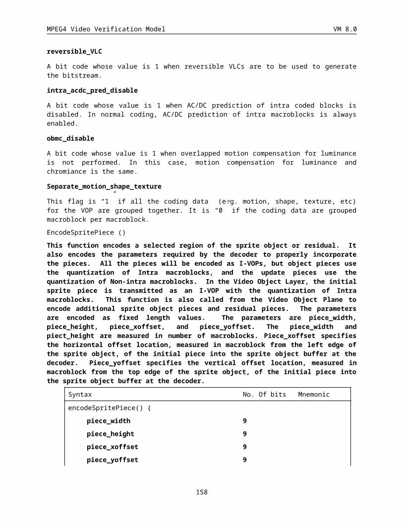
MPEG4 Video Verification Model VM 8.0
Backward MC+Q x -- x --
Forward MC+Q x x -- --
Table 35 Macroblock types and included elements for B-VOPs.
4.9.2.4 Sprite-VOPFor each Sprite-VOP, the Separate syntax consists of first_shape_codes for all macroblocks in the VOP's bounding box, followed by Motion, Shape, and Texture data. The details of the syntax components are provided in the following.
first_shape_code
For each macroblock in the VOP’s bounding box first_shape_code is provided.
1-3 bits
first_shape_code
Motion_coding
The syntax for the motion information related to all macroblocks that belong to the VOP would be:
1-2 bits N bits 1-2 bits N bits
No. of Vectors Encoded vectors ...
No. of Vectors Encoded vectors ...
..........
No. of Vectors: Huffman coded number of motion vectors for each macroblock (0, 1, 4 or sprite).
A `0’ indicates that there is no motion compensation for macroblock. Hence the data coded by the texture coding part will be the actual pixel values in the current image at this macroblock location (INTRA coded) or skipped by the texture coding syntax. A ‘1’ indicates that this macroblock is motion compensated by a 16 x 16 motion vector. Similarly a ‘4’ indicates that this macroblock is motion compensated by 4, 8 x 8 motion vectors. Finally, a ‘sprite’ indicates that no motion vectors are sent and sprite prediction is used, meaning that motion compensation is performed on the basis of the warping specified by the sprite coordinates transmitted in the VOL and their corresponding coordinates transmitted in the VOP.
The Huffman codes used to code this No. of Vectors field are presented in Table 36
Value Length Code
0 2 11
1 1 0
4 3 100
Sprite 3 101
Table 36 VLC table for No. of Vectors.
Encoded vectors: these are differentially coded using the same prediction scheme and Huffman tables, as described in sections., , and ,
Texture_coding
The texture data for the macroblocks belonging to the VOP is coded using a DCT coding as in Combined Motion Shape Texture case. The syntax of the texture coding for each of the macroblocks in the VOP is as follows:
1 bits 1-9 bits 1 bit 1-6 bits 2 bits N bits
158
MPEG4 Video Verification Model VM 8.0
NO_DCT flag MCBPC ACpred_flag CBPY DQUANT DCT data
NO_DCT flag: this flag indicates whether a macroblock has DCT data or not. If it has no DCT data it is set to ‘1’, otherwise it is set to ‘0’. The Huffman Codes used to code the NO_DCT flag are reported in Table 29.
To skip a macroblock, No. of Motion Vectors is set to ‘0’ (i.e. Code = ‘11’) and the NO_DCT flag to ‘1’ (i.e. Code = ‘1’). The skipped marcoblock corresponds to a straight copy from a sprite to the current macroblock on the basis of warping specified by the coordinates on the sprite and the corresponding coordinates on the VOP (i.e. without DCT coefficients).
MCBPC: Mode and Coded Block Pattern Chrominance gives information on i) whether DQUANT is present or not, and ii) coded block pattern for chrominance. The Huffman table for the MCBPC is provided in Table 37.
Value DQUANT CBPC (56) Length Code
0 -- 00 1 1
1 -- 01 3 001
2 -- 10 3 010
3 -- 11 3 011
4 x 00 4 0001
5 x 01 6 0000 01
6 x 10 6 0000 10
7 x 11 6 0000 11
8 stuffing -- 9 0000 0000 1
Table 37 VLC table for the MCBPC for Sprite-VOPs, where “x” means that DQUANT is present.
CBPY: Coded Block Pattern for luminance (Y) specifies those Y blocks in the macroblock for which at least one non-INTRADC transform coefficient is transmitted. The Huffman table for the CBPY is the same as the one used for the Combined Motion Shape Texture coding method (see Sec. ) and presented in Table 31.
DQUANT: define changes in the value of the VOP quantizer. The DQUANT values and respective codes are the same used in the Combined Motion Shape Texture and presented in Table 32.
Macroblock types and included elements for Sprite-VOPs are listed in Table 38
VOP MB type NO_DCT CBPY MCBPC DCT data
DQUANT No.of Vectors
Sprite N.C. x -- -- -- -- x
Sprite INTER x x x x -- x
Sprite INTER+Q x x x x x x
Sprite INTER4V x x x x -- x
Sprite INTER4V+Q x x x x x x
Sprite INTRA x x x x -- x
Sprite INTRA+Q x x x x x x
Sprite DYN-SP x x x x -- x
Sprite DYN-SP+Q x x x x x x
Table 38 Macroblock types and included elements for Sprite-VOPs.
159
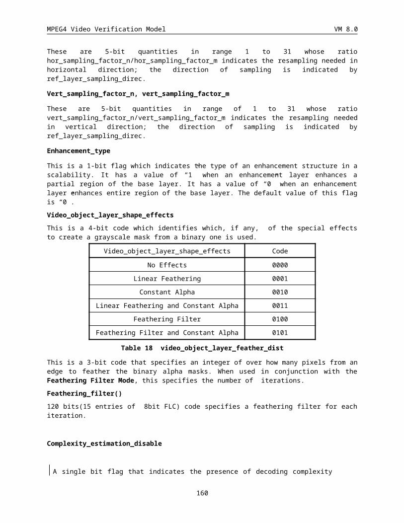
MPEG4 Video Verification Model VM 8.0
To summarize: the macroblock types DYN-SP and DYN-SP+Q are indicated by setting the No. of Vectors to ‘sprite’; the macroblock type N.C. (non-coded) is indicated by No. of Vectors set to 0 and NO_DCT flag set to 1; for all other macroblock types No. of Vectors is set to 0, 1, or 4.
160
MPEG4 Video Verification Model VM 8.0
4.10 Texture Object Layer Class
4.10.1 Texture Object Layer
Syntax No. of bits NoteTextureObjectLayer() {
texture_object_layer_start_code sc+4=28
texture_object_layer_id 4
texture_object_layer_shape 2
if(texture_object_layer_shape == ‘00’) {
texture_object_layer_width 16
texture_object_layer_height 16
}
wavelet_decomposition_levels 8
Y_mean 8
U_mean 8
V_mean 8
Quant_DC_Y 8
Quant_DC_UV 8
for (Y, U, V){
lowest_subband_bitstream_length 16
band_offset 8 (or more)
band_max_value 8 (or more)
lowest_subaband_texture_coding()
}
spatial_scalability_levels 5
quantization_type 2
SNR_length_enable 1
for (i=0; i <spatial_scalability_levels; i++){
spatial_bitstream_length 24
if (quantization_type == 0){
for ( Y, U, V){
Quant 8 skipped for V
wavelet_zero_tree_coding()
161
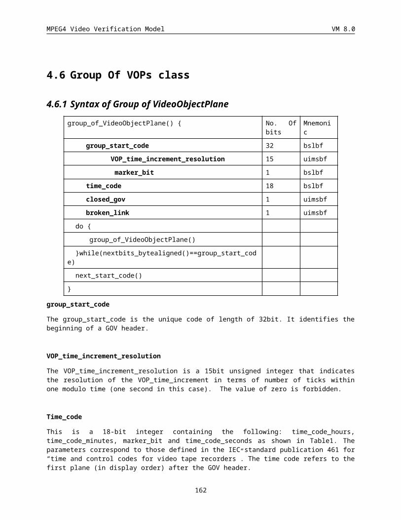
MPEG4 Video Verification Model VM 8.0
}
}
else if ( quantization_type == 2){
SNR_Scalability_Levels 5 skipped for U,V
for(i=0;i<SNR_scalability_levels; i++){
for ( Y, U, V){
Quant 8 skipped for V
SNR_all_zero 1
if( all_zero_flg == 0){
if(SNR_length_enable == 1)
SNR_bitstream_length 16 or more refer to description
wavelet_zero_tree_coding()
}
}
}
}
else {
for ( Y, U, V){
Quant 16
if (SNR_length_enable == 1)
SNR_bitstream_length 16 or more refer to description
wavelet_zero_tree_coding()
}
}
next_start_code()
}
texture_object_layer_start_code
This is a unique code of length 28 bits (sc+4) that preceeds the video_object_layer_id.
texture_object_layer_id
This is a 4-bit code which identifies a video object layer for a video object being processed.
texture_object_layer_shape
This is a 2-bit code which identifies the shape type of video object layer as shown inTable 39.
video_object_layer_shape Code
rectangular 00
162
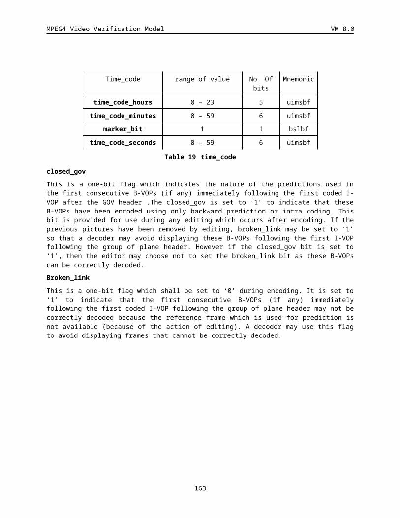
MPEG4 Video Verification Model VM 8.0
binary 01
gray-scale 10
Table 39 Video Object Layer shape types
This flag is “00” if a SOL shape is rectangular, “01” if a SOL has a binary shape (i.e. if each pixel of the rectangle defined by texture_object_layer_width and texture_object_layer_height is either part of a SOL or not), and “10” if a VOL shape is defined by grey scale data (i.e. if each pixel of the rectangle defined by texture_object_layer_width and texture_object_layer_height is to be linearly combined with the pixels of other SOLs at the same spatial location).
texture_object_layer_width, texture_object_layer_height
These two codes define the picture size for the session, in pixels unit (zero values are forbidden). This is also the size of the unique SOL of the session.
wavelet_decomposition_levels
This field indicates the number of levels in the wavelet decomposition of the texture.
Y_mean
This field indicates the mean value of the Y component of the texture.
U_mean
This field indicates the mean value of the U component of the texture.
V_mean
This field indicates the mean value of the V component of the texture.
Quant_DC_Y
This field indicates the quantization step size for the Y component of the lowest subband.
Quant_DC_UV
This field indicates the quantization step size for the U and V components of the lowest subband.
lowest_subband_bitstream_length
This field defines the size of the bitstream for each spatial resolution in bits.
band_offset
This field defines the offset that must be subtracted from each low-low band coefficient after prediction. The format is as the following:
extension (1 bit) value (7 bits)
.
.
.
.
.
.
and the following scripts shows how band_offset is encoded:
while ( band_offset/128 > 0 ){
extension = 1;
put (band_offset%128) in value
band_offset = band_offset>>7;
}
163
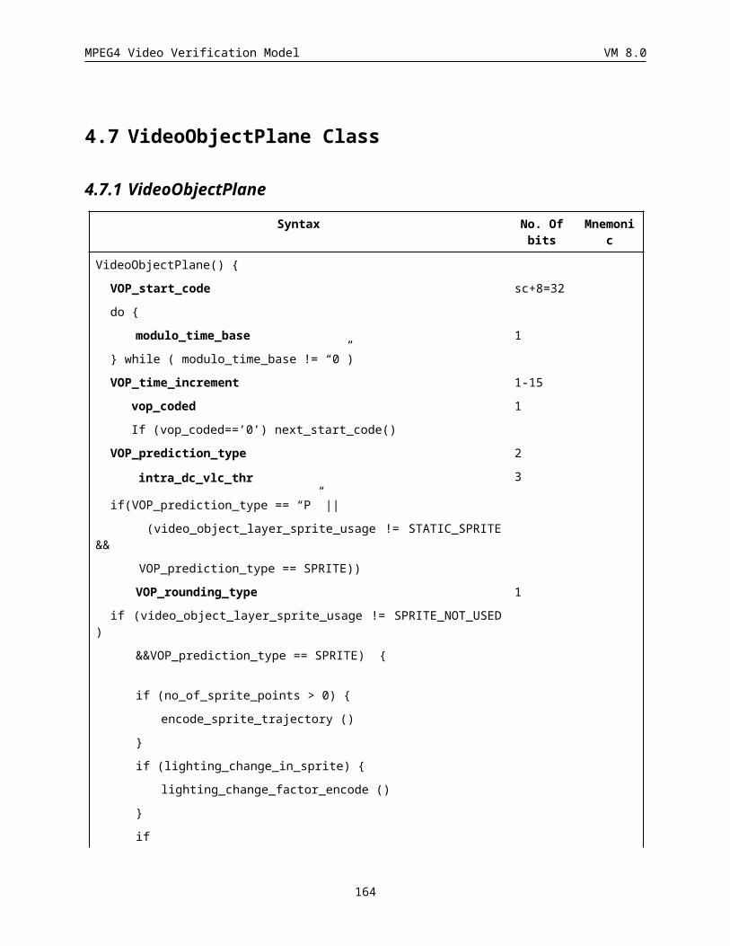
MPEG4 Video Verification Model VM 8.0
extension = 0;
put bitstream_size in value
band_max_value
This field defines the maximum value of the low-low band after prediction. The format is as the following:
extension (1 bit) value (7 bits)
.
.
.
.
.
.
and the following scripts shows how band_max_value is encoded:
while ( band_max_value/128 > 0 ){
extension = 1;
put (band_max_value%128) in value
band_max_value = band_max_value>>7;
}
extension = 0;
put band_max_value in value
spatial_scalababitily_Levels
This field indicates the number of spatial scalability levels supported in the current bitstream.
quantization_type
This field indicates the type of the multi-level quantization type as is shown inTable 40.
Quantization_type Code
single quantizer 0
multiple quantizer 10
bi-level quantizer 11
Table 40 The wavelet scanning method
SNR_length_enable
If this flag is enabled ( disable =0; enabled = 1), each SNR scale starts with a field in which the size of bit stream for that SNR scale is determined.
spatial_bitstream_length
This field defines the size of the bitstream for each spatial resolution in bits.
Quant
This field defines quantization step size for each component.
SNR_Scalability_Levels
This field indicates the number of levels of SNR scalability supported in this spatial scalability level.
SNR_all_zero
This flags indicate whether all the coefficients in the SNR layer are zero or not. The value ‘0’ for this flag indicates that the SNR layer contains some nonzero coefficients which will be coded after this flag. The value ‘1’
164
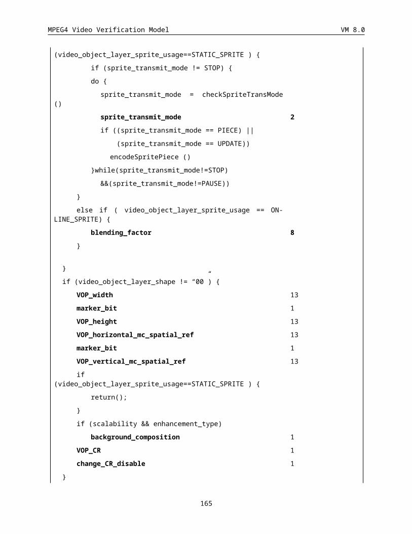
MPEG4 Video Verification Model VM 8.0
for this flag indicates that the current SNR layer only contains zero coefficients and therefore the layer will be skipped.
SNR_bitstream_length
This field defines the size of the bitstream for each specific SNR scale. The format is as the following:
extension (1 bit) length (15 bits)
.
.
.
.
.
.
and the following scripts shows how the bitstream length is coded:
while ( bitstream_size/(2^15)> 0 ){
extension = 1;
put (bitstream_size%(2^15)) in length
bitstream_size = bitstream_size>>15;
}
extension = 0;
put bitstream_size in length
165
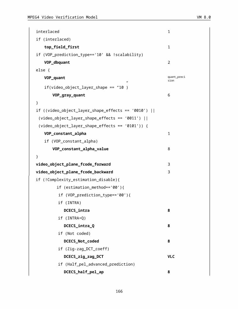
MPEG4 Video Verification Model VM 8.0
5 DECODER DEFINITION
5.1 OverviewThe Figure 66 presents a general overview of the VOP decoder structure. The same decoding scheme is applied when decoding all the VOPs of a given session.
Figure 66: VOP decoder structure.
The decoder is mainly componed of two parts : the shape decoder and the traditional motion & texture decoder. The reconstructed VOP is obtained by the right combination of the shape, texture and motion information. For core experiments, when specified a deblocking filter should be applied to the decoded output, as described in section .
5.2 Shape decodingTo be done
5.3 Decoding of Escape CodeThere are three types of escape codes for DCT coefficients.
Type 1 : the code following ESC + “1” is decoded as variable length codes, using the VLC tables depending on the coding type. The restored values of LEVEL, LEVELS, is obtained as follows :
LEVELS= sign(LEVEL+) x [ abs( LEVEL+) + LMAX ]
where LEVEL+ is the value after variable length decoding. LMAX is given in Table 65 and Table 66.
Type 2 : the code following ESC + “01” is decoded as variable length codes, using the VLC tables depending on the coding type. The restored values of RUN, RUNS, is retrieved as follows :
RUNS= RUN+ + (RMAX + 1)
166
Shape Decoding
MotionDecoding
TextureDecoding
MotionCompensation Reconstucted
VOP
VOP Memory
Demultiplexor
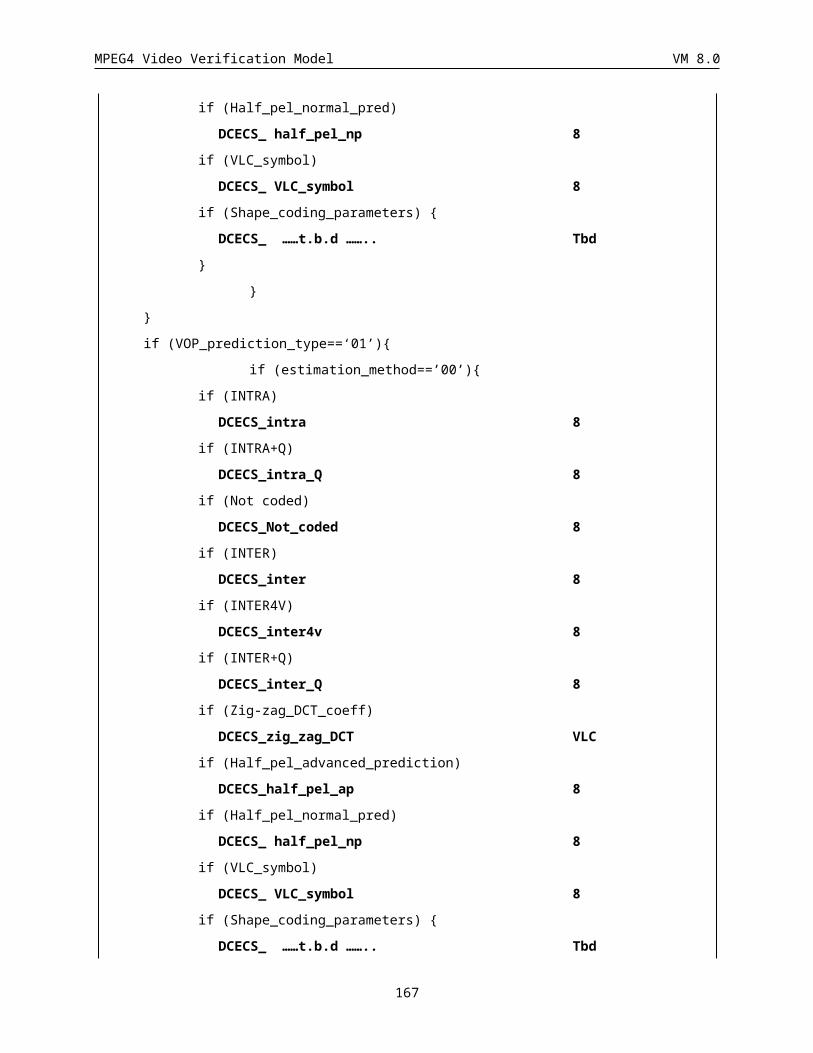
MPEG4 Video Verification Model VM 8.0
where RUN+ is the value after variable length decoding. RMAX is given in Table 67 and Table 68
Type 3 : An escape code following ESC + “00” is decoded as fixed length codes. This type of escape codes are represented by 1-bit LAST, 6-bit RUN and 8-bit LEVEL.
5.4 Temporal Prediction Structure1. A target P-VOP shall make reference for prediction to the most recently decoded I- or P-VOP.If the vop_coded
of the most recently decoded I- or P-VOP is ”0”, the target P-VOP shall make reference to a decoded I- or P-VOP which immediately precedes said most recently decoded I- or P-VOP, and whose vop_code is not zero.
2. A target B-VOP shall make reference for prediction to the most recently decoded forward and/or backward reference VOPs. The target B-VOP shall only make reference to said forward or backward reference VOPs whose vop_coded is not zero. If the vop_coded flags of both most recently decoded forward and backward referfence VOPs are zero, the following rules applies.
· for texture, the predictor of the target B-VOP shall be a gray macroblock of (Y, U, V) = (128, 128, 128).
· for binary alpha planes, the predictor shall be zero (transparent block)
· for grayscale alpha planes, the predictor of the alpha values shall be 128
Note that, binary alpha shape in B-VOP shall make reference for prediction to the most recently decoded forward reference VOP.
1. A decoded VOP whose vop_coded isnot zero but have no shape shall be padded by (128, 128, 128) for (Y, U, V). Similarly, grayscale alpha planes shall be padded with 128.
The temporal prediction structure is depicted in Figure 67.
Object disappears(vop_coded = 0)I0 P1 P2 P3 B4 B6P5 P7
Figure 67: Temporal Prediction Structure.
5.5 Generalized Scalable DecodingWe now discuss the decoding issues in generalized scalable decoding. Considering the case of two layers, a base-layer and an enhancement-layer, the spatial resolution of each layer may be either the same or different; when the layers have different spatial resolution, (up or down) sampling of base-layer with respect to the enhancement-layer
167
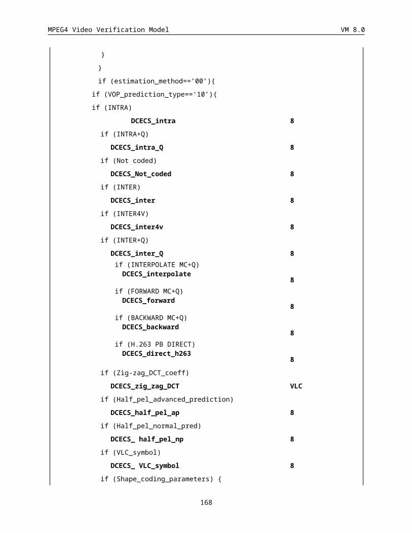
MPEG4 Video Verification Model VM 8.0
becomes necessary for generating predictions. If the lower layer and the enhancement -layer are temporally offset, irrespective of the spatial resolutions, motion compensated prediction may be used between layers. When the layers are coincident in time but at different resolution, motion compensation may be switched off to reduce overhead.
The reference VOPs for prediction are selected by reference_select_code as specified in Table 41 and Table 42. In coding of P-VOPs belonging to an enhancement layer, the forward reference is one of the following three: the most recent decoded VOP of enhancement layer, the most recent VOP of the lower layer in display order, or the next VOP of the lower layer in display order.
In B-VOPs, the forward reference is one of the two: the most recent decoded enhancement VOP or the most recent lower layer VOP in display order. The backward reference is one of the three: the temporally coincident VOP in the lower layer, the most recent lower layer VOP in display order, or the next lower layer VOP in display order.
ref_select_code forward prediction reference
00 Most recent decoded enhancement VOP belonging to the same layer.
01 Most recent VOP in display order belonging to the reference layer.
10 Next VOP in display order belonging to the reference layer.
11 Temporally coincident VOP in the reference layer (no motion vectors)
Table 41 Prediction reference choices for P-VOPs in the object-based temporal scalability.
ref_select_code forward temporal reference backward temporal reference
00 Most recent decoded enhancement VOP of the same layer
Temporally coincident VOP in the reference layer (no motion vectors)
01 Most recent decoded enhancement VOP of the same layer.
Most recent VOP in display order belonging to the reference layer.
10 Most recent decoded enhancement VOP of the same layer.
Next VOP in display order belonging to the reference layer.
11 Most recent VOP in display order belonging to the reference layer.
Next VOP in display order belonging to the reference layer.
Table 42 Prediction reference choices for B-VOPs in the case of scalability.
Temporally coincident VOP in the reference layer (no motion vectors)
The enhancement-layer can contain I-, P- or B-VOPs, but the B-VOPs in the enhancement layer behave more like P-VOPs at least in the sense that a decoded B-VOP can be used to predict the following P- or B-VOPs.
When the most recent VOP in the base layer is used as reference, this includes the VOP that is temporally coincident with the VOP in the enhancement layer. However, this necessitates use of the base layer for motion compensation which requires motion vectors.
If the coincident VOP in the lower layer is used explicitly as reference, no motion vectors are sent and this mode can be used to provide spatial scalability. Spatial scalability in MPEG-2 uses spatio-temporal prediction, which is accomplished here by using the prediction modes available for B-VOPs.
168
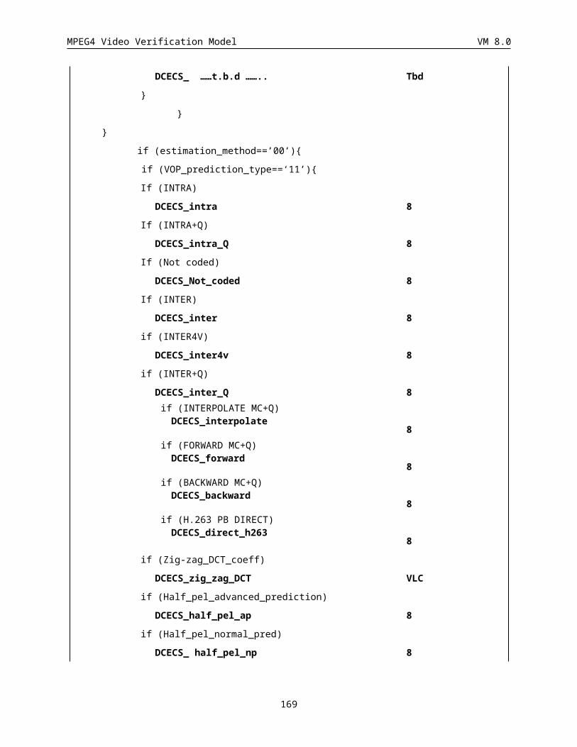
MPEG4 Video Verification Model VM 8.0
5.5.1 Spatial Scalability Decoding
5.5.1.1 Base Layer and Enhancement LayerFor spatial scalability, the output from decoding the base layer only have different spatial resolution from output of decoding both the base layer and the enhancement layer. For example, the resolution of the base layer is QCIF resolution and that of the enhancement layer is CIF resolution. In this case, when the output with QCIF resolution is required, only the base layer is decoded. And when the output with CIF resolution is required, both the base layer and the enhancement layer are decoded.
5.5.1.2 Decoding of Base LayerThe decoding process of the base layer is the same as non_scalable decoding process.
5.5.1.3 Upsampling ProcessThe upsampling process is performed at the midprocessor. The VOP of the base layer is locally decoded and the decoded VOP is upsampled to the same resolution as that of the enhancement layer. In case of the example above, upsampling is performed by the filtering process described in Figure 41 and Table 12.
5.5.1.4 Decoding Process of Enhancement LayerThe VOP in the enhancement layer is decoded as either P-VOP or B-VOP.
5.5.1.5 Decoding of P-VOPs in Enhancement LayerIn P-VOP, the ref_select_code is always “11”, i.e., the prediction reference is set to I-VOP which is temporally coincident VOP in the base layer. In P-VOP, the motion vector is always set to 0 at the decoding process.
5.5.1.6 Decoding of B-VOPs in Enhancement LayerIn B-VOP, the ref_select_code is always “00”, i.e., the backward prediction reference is set to P-VOP which is temporally coincident VOP in the base layer, and the forward prediction reference is set to P-VOP or B-VOP which is the most recent decoded VOP of the enhancement layer. In B-VOP, when the backward prediction, i.e., the prediction from the base layer is selected, the motion vector is always set to 0 at the decoding process.
5.5.2 Temporal Scalability DecodingIn object based temporal scalability, a background composition technique is used in the case of Type 1 scalability as discussed in Section . Background composition is used in forming the background region for objects at the enhancement layer. We now describe the background composition technique referring to Figure 68, where background composition for a current VOP is depicted, where composition is performed using the previous and the next pictures in the base layer (e.g., the background region for the VOP at frame 2 in Figure 43 is composed using frames 0 and 6 in the base layer).
Figure 68 shows the background composition for the current frame at the enhancement layer. The dotted line represents the shape of the selected object at the previous frame in the base layer (called “forward shape”). As the object moves, its shape at the next frame in the base layer is represented by a broken line (called “backward shape”).
For the region outside these shapes, the pixel value from the nearest frame at the base layer is used for the composed frame. These areas are shown as white in Figure 68. For the region occupied by only the selected object
169
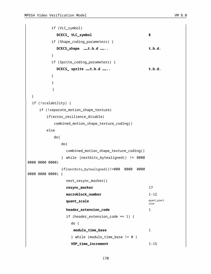
MPEG4 Video Verification Model VM 8.0
of the previous frame at the base layer, the pixel value from the next frame at the base layer is used for the composed frame. This area is shown as lightly shaded in Figure 68. On the other hand, for the region occupied by only the selected object of the next frame at the base layer, pixel values from the previous frame are used. This area is darkly shaded in Figure 68. For the region where the areas enclosed by these shapes overlap, the pixel value is given by padding from the surrounding area. The pixel value which is outside of the overlapped area should be filled before the padding operation.
selected object at theprevious frame : “forwardshape” selected object at
the next frame :“backward shape”
pixel value fromthe next frame
pixel value is given bypadding from thesurrounding area after theother area is filled.
pixel value from theprevious frame
pixel value from theprevious frame
Figure 68: Background composition.
The following process is a mathematical description of the background composition method.
If s(x,y,ta)=0 and s(x,y,td)=0fc(x,y,t) = f(x,y,td) (|t-ta|>|t-td|)fc(x,y,t) = f(x,y,ta) (otherwise),
if s(x,y,ta)=1 and s(x,y,td)=0fc(x,y,t) = f(x,y,td)
if s(x,y,ta)=0 and s(x,y,td)=1fc(x,y,t) = f(x,y,ta)
if s(x,y,ta)=1 and s(x,y,td)=1The pixel value of fc(x,y,t) is given by padding from the surrounding area.
where
fc composed image
f decoded image at the base layer
s shape information (alpha plane)
(x,y) the spatial coordinate
t time of the current frame
ta time of the previous frame
170
MPEG4 Video Verification Model VM 8.0
td time of the next frame
Two types of shape information, s(x, y, ta) and s(x, y, td), are necessary for the background composition. s(x, y, ta) is called a “forward shape” and s(x, y, td) is called a “backward shape” in Section . If f(x, y, td) is the last frame in the bitstream of the base layer, it should be made by copying f(x, y, ta). In this case, two shapes s(x, y, ta) and s(x, y, td) should be identical to the previous backward shape.
When a gray scale alpha plane is used, positive value is regarded as the value “1” of the binary alpha plane. Note that the above technique is based on the assumption that the background is not moving.
5.6 Compositer DefinitionThe output of the decoders are the reconstructed VOP’s that are passed to the compositor. In the compositor the VOP’s are recursively blended in the order specified by the VOP_composition_order.
Each VOP has its own YUV and alpha values. Blending is done sequentially ( two layers at a time). For example, if VOP N is overlayered over VOP M to generate a new VOP P, the composited Y, U, V and alpha values are:
Pyuv = ((255 - Nalpha) * Myuv + (Nalpha * Nyuv ))/255;
Palpha = 255.
In the case that there exists more than two VOPs for a particular sequence, this blending procedure recursively applies to YUV components by taking the output picture as background.
5.7 Flex_0 Composition Layer SyntaxThis section provides information which is not part of the syntax or semantics apecifications of the MPEG video VM. The purpose of this part is to provide information for implementors of the VM who are in need of higher level syntax definitions not part of video.
A composition script describes the arrangement of AV objects in a scene. In Flex_1, this composition script is expressed in a procedural language (such as Java). In Flex_0, this composition script is expressed instead by a fixed set of parameters. That is, the composition script is parametrized. These parameters are encoded and transmitted in a composition layer. This section briefly describes the bitstream syntax of the compositon layer for Flex_0.
5.7.1 Bitstream SyntaxAt any given time, a scene is composed of a collection of objects, according to composition parameters. The composition parameters for an object may be changed at any time by transmitting new parameters for the object. These parameters are timestamped, in order to be transmitted only occasionally if desired.
class SessionParameters {while (! [end_of_session])
uint(30) timestamp; // millisec since last updateCompositionInformation composition_information;
}};map motion_sets_table( int ) {
0b0, 0,0b10, 1,
171
MPEG4 Video Verification Model VM 8.0
0b110, 20b1110, 3,0b1111, 4
};class CompositionInformation {
uint(5) video_object_id;bit(1) visibility;if (visibility) {
bit(1) 3_dimensional;if (!3_dimensional)
uint(5) composition_order;vlc(motion_sets_table) number_of_motion_sets;if (number_of_motion_sets > 0) {
int(10) x_translation;int(10) y_translation;if (3_dimensional)
int(10) z_translation;}if (number_of_motion_sets > 1) {
int(10) x_delta_1;int(10) y_delta_1;if (3_dimensional)
int(10) z_delta_1;if (number_of_motion_sets > 2) {
int(10) x_delta_2;int(10) y_delta_2;if (3_dimensional)
int(10) z_delta_2;}if (number_of_motion_sets > 3) {
int(10) x_delta_3;int(10) y_delta_3;if (3_dimensional)
int(10) z_delta_3;}
}};
5.7.2 Parameter SemanticsThe meaning of the above parameters are:
uint(5) video_object_id The ID of the VO whose composition information this data represents.
boolean visibility Set if the object is visible.
boolean 3_dimensional If set the object has 3D extent else it purely is 2D.
uint(3) number_of_motion_sets Number of X,Y (and Z) data sets provided for translation and rotation.
uint(5) composition_order This field is used to indicate the place in the object stack this object should be visualised. It is used to determine which objects occlude which other objects for 2D composition.
int(10) x_translation, y_translation, z_translation Translation of the object relative to the origin of the scene coordinate system.
int(10) x_delta_n, y_delta_n, z_delta_n Coordinate transformation information as per input contribution m1119.doc
172
MPEG4 Video Verification Model VM 8.0
6 APPENDIX A: COMBINED MOTION SHAPE TEXTURE CODING
This appendix describes the combined motion shape texture coding. The text is based on Draft ITU-T Recommendation H.263 Video Coding for Low Bitrate Communication Sections 5.3 and 5.4. Annexes describing optional modes can be found in that document.
6.1 Macroblock LayerData for each macroblock consists of a macroblock header followed by data for blocks. The macroblock layer structure in I or P VOPs is shown in Figure 1MB. First_shape_code is only present for which video_object_layer_shape!=”00”. COD is only present in VOPs for which VOP_prediction_type indicates P-VOPs (VOP_prediction_type==‘01’) or SPRITE-VOP (VOP_prediction_type==’11’), and the corresponding macroblock is not transparent. MCBPC is present when indicated by COD or when VOP_prediction_type indicates I-VOP (VOP_prediction_type== ‘00’). CBPY, DQUANT, and MVD2-4 are present when indicated by MCBPC. Block Data is present when indicated by MCBPC and CBPY. MVD2-4 are only present in Advanced Prediction mode. MVDs is only present when first_shape_code indicates MVDs!=0. CR is present when change_CR_disable is 0. ST and BAC are present when First_shape_code indicates intraCAE or interCAE. Aacpred_flag/ACpred_flag are present when MCBPC indicates INTRA or INTRA+Q, and when intra_acdc_pred_disable flag is OFF. Interlaced_information contains the dct_type flag and field motion vector reference field. All fields from COD to Block Data are skipped if video_object_layer_shape is ‘11’.
First_shape_code MVD_shape
CR ST BAC
COD MCBPC
AC_pred_flag CBPY DQUANT Interlaced_information
MVD MVD2 MVD3 MVD4
CODA Alpha_ACpred_flag CBPA
Alpha Block Data Block Data
Table 43 Structure of macroblock layer in I-, and P-VOPs
The macroblock layer structure in Sprite-VOPs (VOP_prediction_type == “11”) is shown in Table 44. The only difference from the syntax of I- and P-VOPs is that a 1-bit code, MCSEL, signaling the use of sprites (or GMC) is introduced just after MCBPC. MCSEL is only present when the macroblock type specified by the MCBPC is INTER or INTER+Q. All fields from COD to Block Data are skipped if video_object_layer_shape is ‘11’.
First_shape_code
MVD_shape CR ST BAC
COD MCBPC MCSEL
AC_pred_flag CBPY DQUANT MVD MVD2 MVD3 MVD4
CODA Alpha_ACpred_flag
CBPA Alpha Block Data Block Data
Table 44 structure of macroblock layer in Sprite-VOPs
The macroblock layer structure in B-VOPs (VOP_prediction_type== ‘10’) is shown inTable 45. If COD indicates skipped (COD == ‘1’) for a MB in the most recently decoded I- or P-VOP then the co-located MB in B-VOP is also skipped (no information is included in the bitstream). Otherwise, the macroblock layer is as shown in Table45.
However in the case of the enhancement layer of spatial scalability (ref_select_code == ‘00’ && scalability == 1), regardless of COD for a MB in the most recently decoded I- or P-VOP, the macroblock layer is as shown in Table 45
173
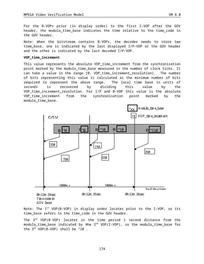
MPEG4 Video Verification Model VM 8.0
first_shape_code MVD_shape CR ST BAC
MODB MBTYPE
CBPB DQUANT Interlaced_information
MVDf MVDb MVDB
CODA CBPBA
Alpha Block Data Block Data
Table 45 Structure of macroblock layer in B VOPs
MODB is present for every coded (non-skipped) macroblock in B-VOP. MVD’s (MVD f, MVDb, or MVDB) and CBPB are present if indicated by MODB. Macroblock type is indicated by MBTYPE which signals motion vector modes (MVD’s) and quantization (DQUANT). All fields from COD to Block Data are skipped if video_object_layer_shape is ‘11’.
In the case of VOP_CR is not equal to 1, when VOP level size conversion is carried out, one binary alpha block is corresponding to 4 (VOP_CR=1/2) texture macroblocks. (see Figure 69) Thus, a binary alpha data (first_shape_code to CAE) precede the texture macroblock with the same top left coordinates. For example, the binary alpha block BAB(2i,2j) is located at same position of texture macroblock MB(2i,2j), MB(2i,2j+1), MB(2i+1,2j) and MB(2i+1,2j+1) (Figure 69), then combined bitstream is shown in Figure 70.
MB(2i,2j) MB(2i,2j+1) MB(2i,2j+2) MB(2i,2j+3)
MB(2i+1,2j) MB(2i+1,2j+1)MB(2i+1,2j+2) MB(2i+1,2j+3)
BAB(2i,2j) BAB(2i,2j+1)
Figure 69 Binary Alpha Blocks and corresponding texture MBs
BAB(2i,2j) MB(2i,2j) MB(2i,2j+1) BAB(2i,2j+2)
MB(2i,2j+2) MB(2i,2j+3)
MB(2i+1,2j) MB(2i+1,2j+1)
MB(2i+1,2j+2)
MB(2i+1,2j+3)
Figure 70 combined bitstream of binary alpha blocks and texture blocks
6.1.1 Coded macroblock indication (COD) (1 bit)A bit which when set to "0" signals that the macroblock is coded. If set to "1", no further information is transmitted for this macroblock; in that case for P-VOPs, the decoder shall treat the macroblock as a ‘P’ macroblock with motion vector for the whole block equal to zero and with no coefficient data; for Sprite-VOP the macroblock data is obtained by a straight copy of data from the sprite on the basis of the warping specified by the warping parameters. COD is only present in VOPs for which VOP_prediction_type indicates ‘P’ or Sprite, for each macroblock in these VOPs.
6.1.2 Macroblock type & Coded block pattern for chrominance (MCBPC) (Variable length)
A variable length codeword giving information about the macroblock type and the coded block pattern for chrominance. The codewords for MCBPC are given in Table 46 and Table 47. MCBPC is always included in coded macroblocks.
174
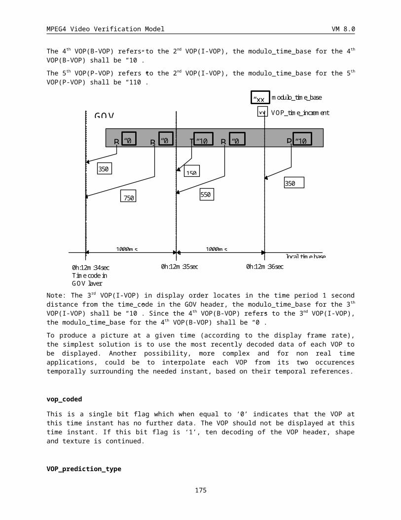
MPEG4 Video Verification Model VM 8.0
An extra codeword is available in the tables for bit stuffing. This codeword should be discarded by decoders.
The macroblock type gives information about the macroblock and which data elements are present. Macroblock types and included elements are listed in Table 46, Table 47, and Table 48.
Index MB type CBPC
(56)
Number of bits Code
0 3 00 1 11 3 01 3 001
2 3 10 3 010
3 3 11 3 011
4 4 00 4 0001
5 4 01 6 0000 01
6 4 10 6 0000 10
7 4 11 6 0000 11
8 Stuffing -- 9 0000 0000 1
Table 46 VLC table for MCBPC (for I-VOPs)
The coded block pattern for chrominance signifies CB and/or CR blocks when at least one non-INTRADC transform coefficient is transmitted (INTRADC is the dc-coefficient for ‘I’ blocks). CBPCN = 1 if any non-INTRADC coefficient is present for block N, else 0, for CBPC5 and CBPC6 in the coded block pattern. Block numbering is given in Figure 71. When MCBPC=Stuffing, the remaining part of the macroblock layer is skipped. In this case, the preceeding COD=0 is not related to any coded or not-coded macroblock and therefore the macroblock number is not incremented. For P-VOPs, multiple stuffings are accomplished by multiple sets of COD=0 and MCBPC=Stuffing.
1 2
3 4
5 6
C R C B Y
Figure 71: Arrangement of blocks in a macroblock
Index MB type CBPC
(56)
Number of bits Code
0 0 00 1 1
1 0 01 4 0011
2 0 10 4 0010
3 0 11 6 0001 01
4 1 00 3 011
5 1 01 7 0000 111
175
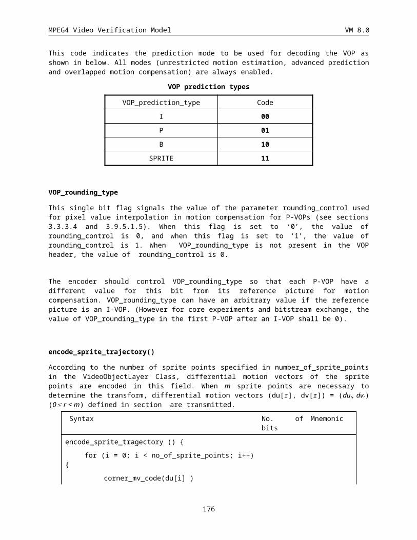
MPEG4 Video Verification Model VM 8.0
6 1 10 7 0000 110
7 1 11 9 0000 0010 1
8 2 00 3 010
9 2 01 7 0000 101
10 2 10 7 0000 100
11 2 11 8 0000 0101
12 3 00 5 0001 1
13 3 01 8 0000 0100
14 3 10 8 0000 0011
15 3 11 7 0000 011
16 4 00 6 0001 00
17 4 01 9 0000 0010 0
18 4 10 9 0000 0001 1
19 4 11 9 0000 0001 0
20 Stuffing -- 9 0000 0000 1
Table 47 VLC table for MCBPC (for P-VOPs)
VOP type MB
type index
Name COD MCBPC MCSEL CBPY DQUANT MVD MVD2-4
P not coded - X
P 0 INTER X X X X
P 1 INTER+Q X X X X X
P 2 INTER4V X X X X X
P 3 INTRA X X X
P 4 INTRA+Q X X X X
P stuffing - X X
I 3 INTRA X X
I 4 INTRA+Q X X X
I stuffing - X
Sprite not coded STAT-SP X
Sprite 0 INTER X X X X X*1
Sprite 1 INTER+Q X X X X X X*1
Sprite 2 INTER4V X X X X X
Sprite 3 INTRA X X X
Sprite 4 INTRA+Q X X X X
Note: “x” means that the item is present in the macroblock.
176
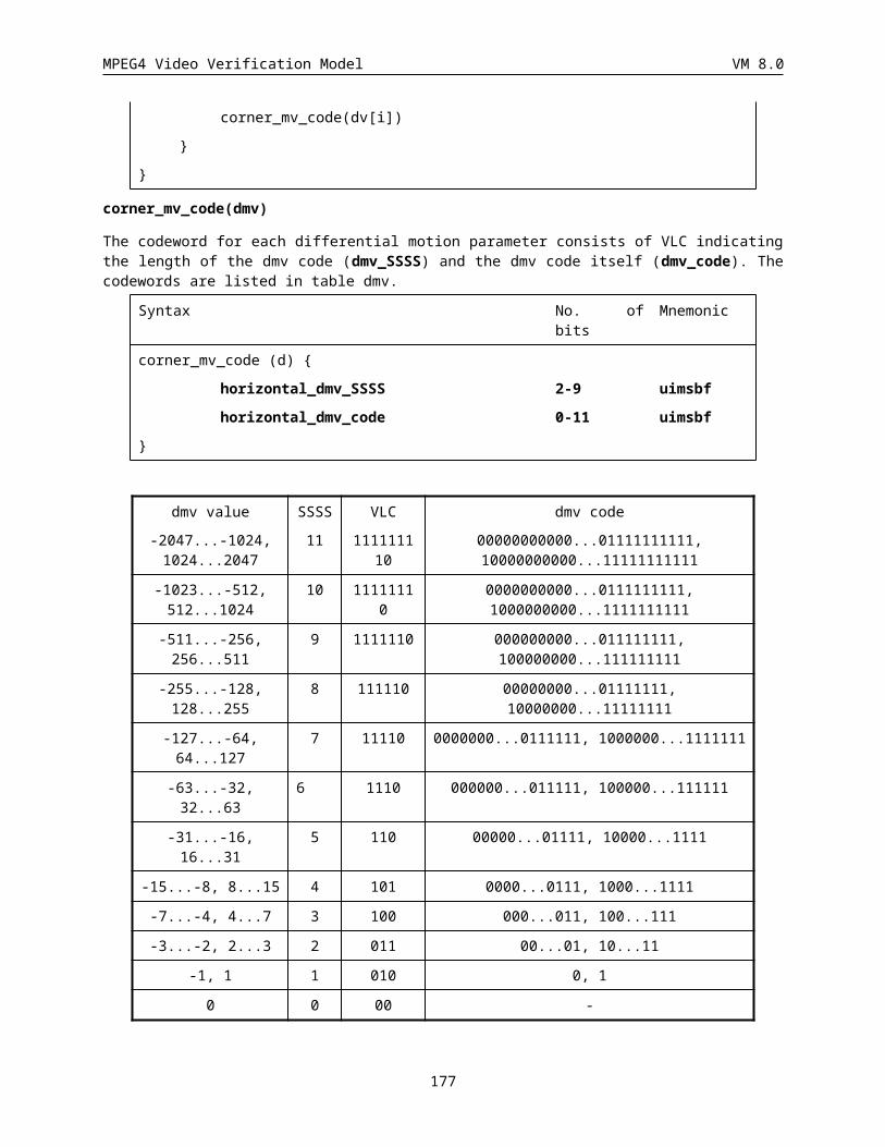
MPEG4 Video Verification Model VM 8.0
*1 MVDs are present only when MCSEL = “0”.
Table 48 Macroblock types and included data elements for a VOP
VOP Type
Index Name COD MCBPC MCSEL CBPY DQUANT MVD MVD2-4
P not coded - X
P 1 INTER X X X
P 2 INTER+Q X X X X
P 3 INTRA X X X
P 4 INTRA+Q X X X X
P stuffing - X X
Table 49 Macroblock types and included data elements for a P-VOP (scalability and ref_select_codd ==`11`
The list of macroblock types for I- and P-VOPs is extended to support dynamic sprite coding and GMC as shown in Table 32.
Referring to the table, when COD = 1 (STAT-SP), the macroblock data is obtained by a straight copy of data from a sprite to the current macroblock on the basis of the warping specified by the coordinates on the sprite and their corresponding coordinates on the VOP. Note that choosing a STAT-SP mode for every macroblock in the VOP corresponds to setting the video_object_layer_sprite_usage field in the VOL to STATIC_SPRITE.
The next two modes, INTER and INTER+Q, specify that the macroblock is predicted from the sprite or the previous reconstructed VOP. For INTER and INTER+Q cases, the following codeword, MCSEL, indicates whether the sprite or the previous reconstructed VOP is referred to. If the previous reconstructed VOP is used as the reference (local MC), MCSEL should be “0”. If sprite prediction or GMC is used, MCSEL should be “1”. Note that the local motion vectors (MVDs) are not transmitted when sprite or GMC is used (MCSEL = 1).
The other three modes, INTER4V, INTRA, and INTRA+Q, are just the same as those used in P-VOPs.
6.1.3 MC reference indication (MCSEL) (1bit)MCSEL is a 1-bit code which specifies the reference image of the macroblock in Sprite-VOPs. This flag is present only when the macroblock type specified by the MCBPC is INTER or INTER+Q as shown in Table 44. MCSEL indicates whether a sprite or the previous reconstructed VOP is referred to when video_object_sprite_usage == ON-LINE_SPRITE. MCSEL also indicates whether the global motion compensated image or the previous reconstructed VOP is referred to when video_object_sprite_usage == GMC. This flag is set to “1” when prediction from the sprite or GMC is used for the macroblock, and is set to “0” if local MC is used. If MCSEL = “1”, local motion vectors (MVDs) are not transmitted.
6.1.4 Intra Prediction Acpred_flag (1bit)ACpred_flag is a 1 bit flag which when set to “0” indicates that only Intra DC prediction is performed. If set to “1” it indicates that Intra AC prediction is also performed in addition to Intra DC prediction according to the rules in section .
6.1.5 Coded block pattern for luminance (CBPY) (Variable length)Variable length codeword giving a pattern number signifying those non transparent Y blocks in the macroblock for which at least one non-INTRADC transform coefficient is transmitted (INTRADC is the dc-coefficient for INTRA blocks.
177
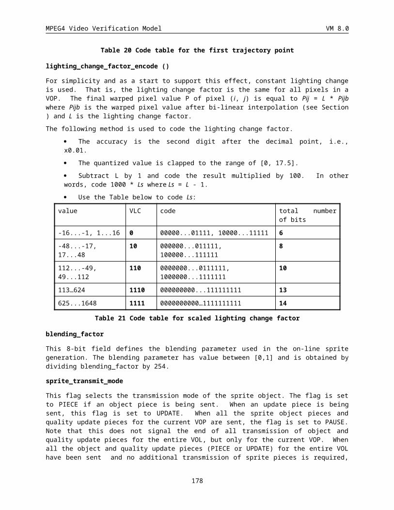
MPEG4 Video Verification Model VM 8.0
For only non transparent blocks, CBPYN = 1 if any non-INTRADC coefficient is present for block N, else 0, for each bit CBPYN in the coded block pattern. The coded block pattern for transparent blocks is not transmitted. Block numbering for a fully non transparent macroblock is given in Figure 71. In case of any transparent blocks, the numbering pattern follows the same order but increments only for transparent blocks. The utmost left bit of CBPY corresponding to the first non transparent block number 1. For a certain pattern CBPYN, different codewords are used for INTER and INTRA macroblocks as defined in the following . If there is only one non transparent block in the macroblock a single bit CBPY is used (1: coded, 0:non coded).
In the case of two non transparent blocks the CBPY is coded according to the following table:
Index CBPY (Intra
MB)
CBPY
(INTER, SPRITE MB)
Number of bits
Code
0 00 11 3 111
1 01 10 3 110
2 10 01 2 10
3 11 00 1 0
In the case of three non transparent blocks the CBPY is coded as follows:
Index CBPY (Intra
MB)
CBPY
(INTER, SPRITE)
Number of bits
Code
0 000 111 3 100
1 001 110 5 11111
2 010 101 5 11110
3 011 100 3 101
4 100 011 5 11101
5 101 010 5 11100
6 110 001 3 110
7 111 000 1 0
Finally for fully non transparent macroblocks the CBPY codewords are given in Table 52.
6.1.6 Quantizer Information (DQUANT) (1 or 2 bits)A one or two bit code to define change in VOP_quantizer. In Table 50 and Table 51 the differential values for the different codewords are given. VOP_quantizer ranges from 1 to 31; if the value for VOP_quantizer after adding the differential value is less than 1 or greater than 31, it is clipped to 1 and 31 respectively. Note that the DQUANT can take values, -2, 0, or 2 in the case of B-VOPs and these values are coded differently from other VOP types.
Index Differential value
DQUANT
0 -1 00
1 -2 01
2 1 10
3 2 11
178
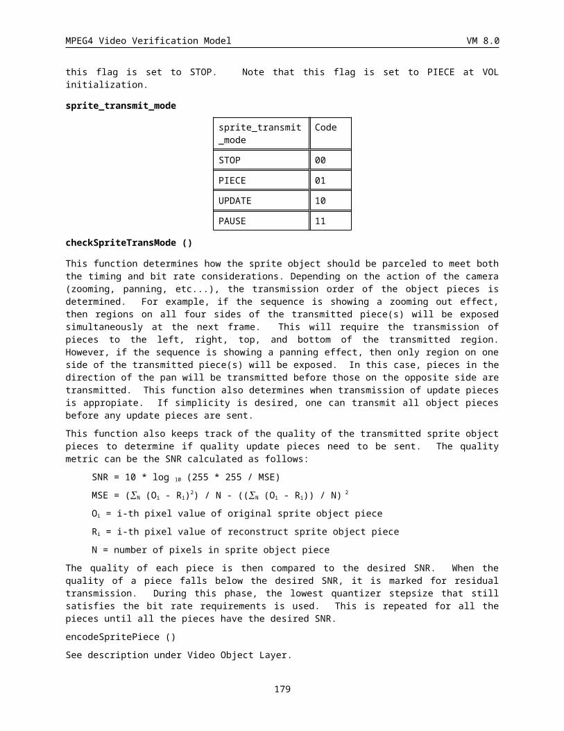
MPEG4 Video Verification Model VM 8.0
Table 50 DQUANT codes and differential values for VOP_quantizer
Index Differential value
DQUANT
0 -2 10
1 0 0
2 2 11
Table 51 DQUANT codes and differential values for VOP_quantizer for B-VOPs
Index CBPY I
(12
34)
CBPY P,SPRITE
(12
34)
Number
of bits
Code
0 00
00
11
11
4 0011
1 00
01
11
10
5 0010 1
2 00
10
11
01
5 0010 0
3 00
11
11
00
4 1001
4 01
00
10
11
5 0001 1
5 01
01
10
10
4 0111
6 01
10
10
01
6 0000 10
7 01
11
10
00
4 1011
8 10
00
01
11
5 0001 0
9 10
01
01
10
6 0000 11
10 10
10
01
01
4 0101
11 10
11
01
00
4 1010
12 11
00
00
11
4 0100
13 11
01
00
10
4 1000
14 11
10
00
01
4 0110
179
MPEG4 Video Verification Model VM 8.0
15 11
11
00
00
2 11
Table 52 VLC table for CBPY of fully non transparent macroblocks
6.1.7 Interlaced video coding information (Interlaced_information)This syntax is only present if the interlaced flag in the VOP header is ‘1’.
if(interlaced){
if((mbtype==INTRA)|¦(mbtype==INTRA_Q)||(cbp!=0))
dct_type 1 uimsbf
if((P_VOP&&((mbtype==INTER)||(mbtype==INTER_Q)))
¦¦(B_VOP&&(mbtype!=Direct_mode)))
field_prediction 1
if (field_prediction)
if(P_VOP|| (B_VOP && (mbtype != Backward))) {
forward_top_field_reference 1 uimsbf
forward_bottom_field_reference
}
if (B-VOP && (mbtype != Forward)) {
backward_top_field_reference 1 uimsbf
backward_bottom_field_reference 1 uimsbf
}
}
}
}
The value of dct_type is 1 if the field DCT permutation of lines is used. The value of field_prediction is 1 if the macroblock is predicted using field motion vectors and 0 for 16x16 motion compensation. The reference field flags have value 0 for the top field and 1 for the bottom field.
For P-VOPs, when field_prediction is 1, two motion vector differences follow the above syntax, top field motion vector followed by bottom field motion vector. For B-VOPs, when field_prediction is 1, two or four motion vector differences are encoded. The B-VOP order of motion vectors for an interpolated macroblock is top field forward, bottom field forward, top field backward, bottom field backward. For uni-directional interlaced B-VOP prediction, the top field motion vector is followed by the bottom field motion vector.
6.1.8 Motion Vector CodingMotion vectors for predicted and interpolated VOPs are coded differentially obeying the following rules:
· In P-VOPs, differential motion vectors are generated as described in and In advanced prediction mode, no motion information needs to be transmitted for transparent blocks (This sentence needs to be reedited).
· In B-VOPs, differential motion vectors are generated as described in
180
MPEG4 Video Verification Model VM 8.0
The VLC used to encode the differential motion vector data depends upon the range of the vectors. The maximum range that can be represented is determined by the forward_f_code and backward_f_code encoded in the VOL header.
The differential motion vector component is calculated. Its range is compared with the values given in Table 53 and is reduced to fall in the correct range by the following algorithm:
if (diff_vector < -range)diff_vector = diff_vector + 2*range;
else if (diff_vector > range-1)diff_vector = diff_vector - 2*range;
forward_f_code
or backward_f_code
Range in half sample
units
1 [-32,31]
2 [-64,63]
3 [-128,127]
4 [-256,255]
5 [-512,511]
6 [-1024,1023]
7 [-2048,2047]
Table 53 Range for motion vectors
This value is scaled and coded in two parts by concatenating a VLC found from Table 54 and a fixed length part according to the following algorithm:
Let f_code be either the forward_f_code or backward_f_code as appropriate, and diff_vector be the differential motion vector reduced to the correct range.
if (diff_vector == 0) {residual = 0;vlc_code_magnitude = 0;
}else {
scale_factor = 1 << (f_code - 1);residual = (abs(diff_vector) - 1) % scale_factor;vlc_code_magnitude = ((abs (diff_vector) - residual + (scale_factor - 1)) /
scale_factor;}
vlc_code_magnitude and the sign of diff_vector are encoded according to Table 54. The residual is encoded as a fixed length code using (f_code-1) bits. If f_code is 1 or if diff_vector is 0 then the residual is not coded
6.1.9 Motion vector data (MVD) (Variable length)MVD is included for all INTER macroblocks and consists of a variable length codeword for the horizontal component followed by a variable length codeword for the vertical component. Variable length codes are given in Table 54.
Index Vector differences Bit number Codes
0 -16 13 0000 0000 0010 1
1 -15.5 13 0000 0000 0011 1
2 -15 12 0000 0000 0101
181
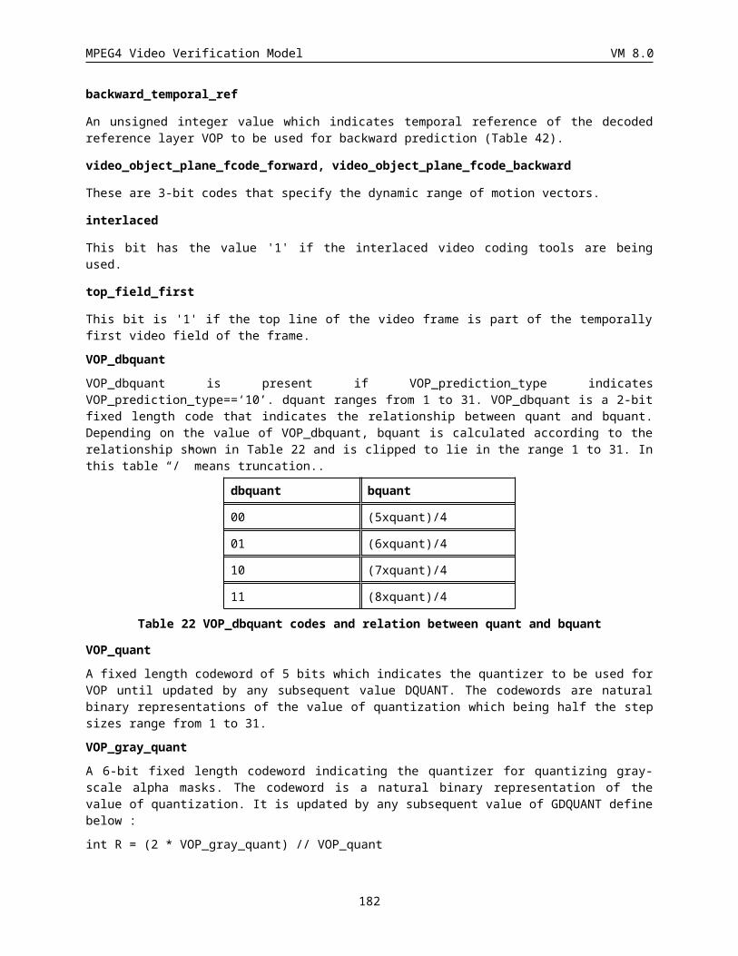
MPEG4 Video Verification Model VM 8.0
3 -14.5 12 0000 0000 0111
4 -14 12 0000 0000 1001
5 -13.5 12 0000 0000 1011
6 -13 12 0000 0000 1101
7 -12.5 12 0000 0000 1111
8 -12 11 0000 0001 001
9 -11.5 11 0000 0001 011
10 -11 11 0000 0001 101
11 -10.5 11 0000 0001 111
12 -10 11 0000 0010 001
13 -9.5 11 0000 0010 011
14 -9 11 0000 0010 101
15 -8.5 11 0000 0010 111
16 -8 11 0000 0011 001
17 -7.5 11 0000 0011 011
18 -7 11 0000 0011 101
19 -6.5 11 0000 0011 111
20 -6 11 0000 0100 001
21 -5.5 11 0000 0100 011
22 -5 10 0000 0100 11
23 -4.5 10 0000 0101 01
24 -4 10 0000 0101 11
25 -3.5 8 0000 0111
26 -3 8 0000 1001
27 -2.5 8 0000 1011
28 -2 7 0000 111
29 -1.5 5 0001 1
30 -1 4 0011
31 -0.5 3 011
32 0 1 1
33 0.5 3 010
34 1 4 0010
35 1.5 5 0001 0
36 2 7 0000 110
37 2.5 8 0000 1010
38 3 8 0000 1000
182
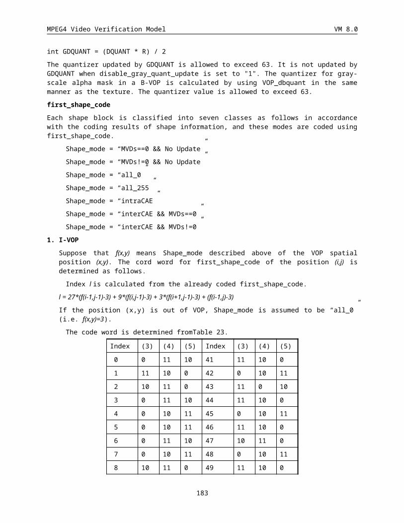
MPEG4 Video Verification Model VM 8.0
39 3.5 8 0000 0110
40 4 10 0000 0101 10
41 4.5 10 0000 0101 00
42 5 10 0000 0100 10
43 5.5 11 0000 0100 010
44 6 11 0000 0100 000
45 6.5 11 0000 0011 110
46 7 11 0000 0011 100
47 7.5 11 0000 0011 010
48 8 11 0000 0011 000
49 8.5 11 0000 0010 110
50 9 11 0000 0010 100
51 9.5 11 0000 0010 010
52 10 11 0000 0010 000
53 10.5 11 0000 0001 110
54 11 11 0000 0001 100
55 11.5 11 0000 0001 010
56 12 11 0000 0001 000
57 12.5 12 0000 0000 1110
58 13 12 0000 0000 1100
59 13.5 12 0000 0000 1010
60 14 12 0000 0000 1000
61 14.5 12 0000 0000 0110
62 15 12 0000 0000 0100
63 15.5 13 0000 0000 0011 0
64 16 13 0000 0000 0010 0
Table 54 VLC table for MVD
6.1.10 Motion vector data (MVD2-4) (Variable length)The three codewords MVD2-4 are included if indicated by VOP_prediction_type and by MCBPC, and consist each of a variable length codeword for the horizontal component followed by a variable length codeword for the vertical component of each vector. Variable length codes are given in Table 54.
If this P-VOP is interlaced, and field_prediction is '1' for this macroblock, the a total of two field motion vectors are present. The top field vector is followed by the bottom field vector and each vector consists of the horizontal component followed by the vertical component. The vector components are encoded as decribed above.
183
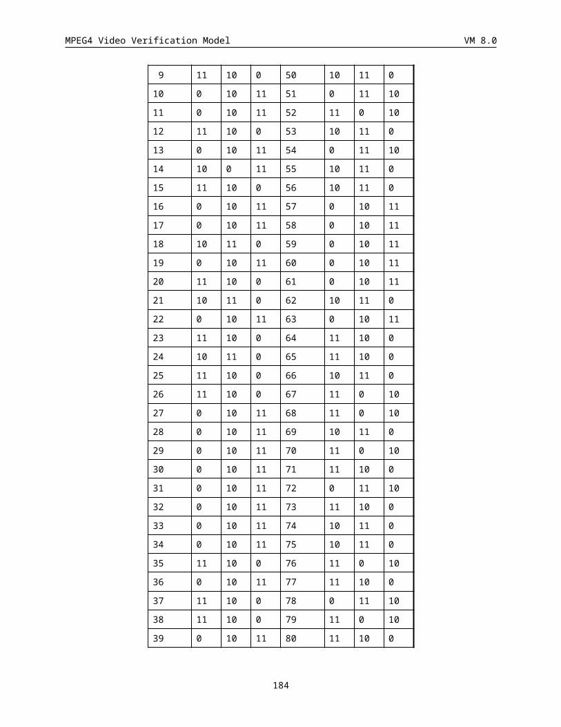
MPEG4 Video Verification Model VM 8.0
6.1.11 Macroblock mode for B-blocks (MODB) (Variable length)MODB is present only in coded macroblocks belonging to B-VOPs. The meaning of this codeword is same as that in H.263. It is a variable length codeword indicating whether MBTYPE and/or CBPB information is present. In case MBTYPE dos not exist the default is set to "Direct (H.263 B)". In the case of the enhancement layer of spatial scalability (ref_select_code == ‘00’ && scalability == ‘1’), the default of MBTYPE is set to “Forward MC” (precdiction from the last decoded VOP in the same reference layer). The codewords for MODB are defined in Table 55.
Index CBPB MBTYPE Number of bits
Code
0 1 0
1 X 2 10
2 X X 2 11
Note: “x” means that the item is present in the macroblock
Table 55 VLC table for MODB
The skipped Macroblock for B-VOPs can be summarized as the following conditions.
1. (ref_select_code == ‘00’ && scalability != ‘0’) && MODB == ‘0’
In this case, further information is not transmitted for this macroblock. The decoder treat the prediction of this macroblock as forward MC with motion vector equal to zero.
2. (ref_select_code != ‘00’ || scalability == ‘0’) && (COD indicates skipped (COD == ‘1’) for a MB in the most recently decoded I- or P-VOP)
In this case, further information is not transmitted for this macroblock. The decoder treat the prediction of this macroblock as forward MC with motion vector equal to zero.
3. (ref_select_code != ‘00’ || scalability == ‘0’) && MODB == ‘0’
In this case, further information is not transmitted for this macroblock. The decoder treat the prediction of this macroblock as Direct (H.263B).
6.1.12 Macroblock Type (MBTYPE) for Coded B-VOPs (Variable length)MBTYPE is present only in coded macroblocks belonging to B-VOPs. Furthermore, it is present only in those macroblocks where at least one MVD is sent. MBTYPE indicates the type of macroblock coding used, for example, H.263 like motion compensation or MPEG-1 like motion compensation with forward, backward or interpolated, and change of quantizer if any by use of DQUANT. The codewords for MBTYPE are defined in Table 56 and Table 57. In the case of the enhancement layer of spatial scalability, MBTYPE is defined in Table57. Otherwise MBTYE is defined in Table 56.
Index MBTYPE DQUANT MVDf MVDb MVDB Number of bits
Code
0 Direct (H.263 B) X 1 1
1 Interpolate MC + Q X X X 2 01
2 Backward MC + Q X X 3 001
3 Forward MC + Q X X 4 0001
Note: “x” means that the item is present in the macroblock
184
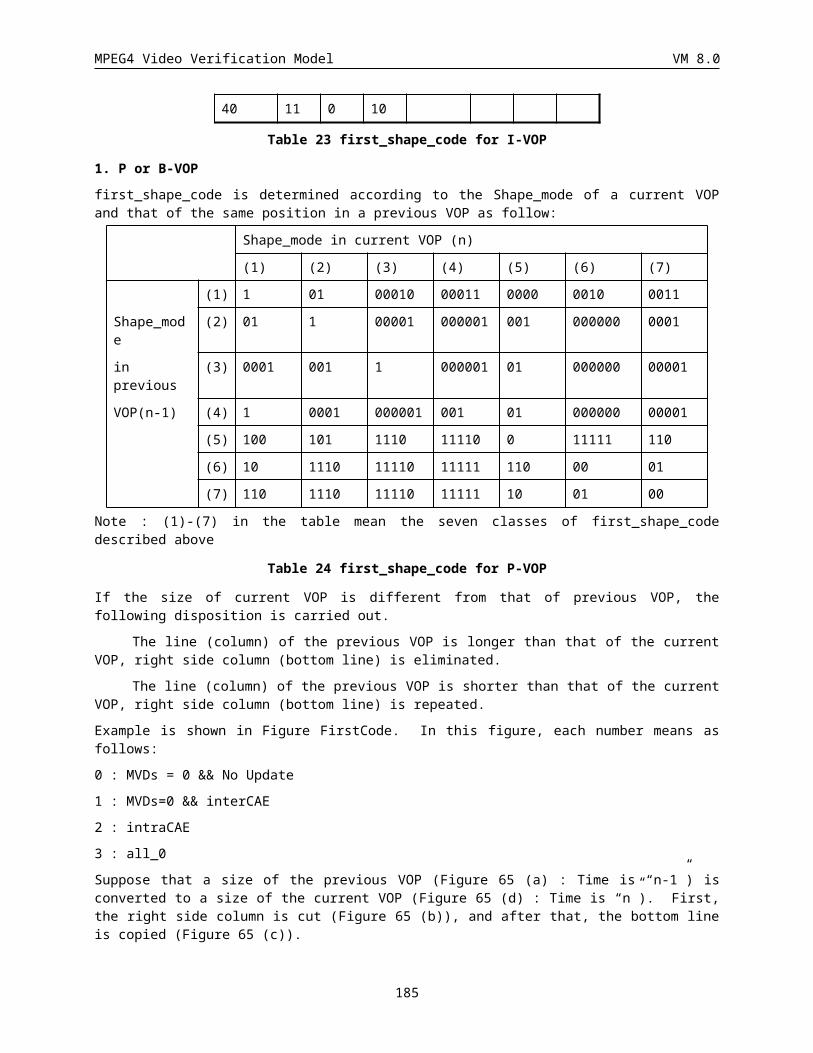
MPEG4 Video Verification Model VM 8.0
Table 56 MBTYPES and included data elements in coded macroblocks in B-VOPs (ref_select_code != ‘00’||scalability==’0’)
Index MBTYPE DQUANT MVDf MVDb Number of bits
Code
0 Interpolate MC + Q X X 2 01
1 Backward MC + Q X 3 001
2 Forward MC + Q X X 1 1
Note: x” means that the item is present in the macroblock
Table 57 MBTYPES and included data elements in coded macroblocks in B-VOPs (ref_select_code == ‘00’&&scalability!=’0’)
Rather than refer to each MBTYPE by an index or by its long explanation in terms of MC mode and Quantizer information, we refer to them as a coding mode which means the following.
· Direct Coding (Direct MC, no new Q)
· Bidirectional Coding (Interpolate MC + Q)
· Backward Coding (Backward MC + Q)
· Forward Coding (Forward MC +Q)
6.1.13 Coded block pattern for B-blocks (CBPB) (3-6 bits)CBPB is only present in B-VOPs if indicated by MODB. For all non transparent blocks, CBPB N = 1 if any coefficient is present for a block N, else 0, for each bit CBPBN in the coded block pattern. The numbering of blocks has been shown earlier, the utmost left bit of CBPB corresponds to block number 1. When MODB = 0 or 1, the default value of CBPB is set to 0 which means that no coefficients are sent.
6.1.14 Quantizer Information for B-Macroblocks (DQUANT) (2 bits)The meaning of DQUANT and the codewords employed are the same as that in I- or P-VOPs. The computed quantizer is scaled by a factor depending on the selected global quantizer scale for B-VOP’s, DBQUANT.
DQUANT is transmitted when CBPB != 0. If CBPB == 0, DQUANT is not transmitted. If CBPB is not transmitted, the default value of CBPB is set to 0.
6.1.15 Motion vector data for Forward Prediction (MVDf) (Variable length)
MVDf is the motion vector of a macroblock in B-VOP with respect to temporally previous reference VOP (an I- or a P-VOP). It consists of a variable length codeword for the horizontal component followed by a variable length codeword for the vertical component. The variable length codes employed are the same ones as used for MVD and MVD2-4 for P-VOPs.
For an interlaced B-VOP macroblock with field_prediction of '1' and MBTYPE of forward or interpolate, MVD f
represents a pair of field motion vectors (top field followed by bottom field) which reference the past anchor VOP. Each of the field motion vectors uses the same encoding as described for the P_VOP MVD field.
185
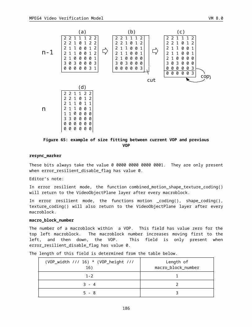
MPEG4 Video Verification Model VM 8.0
6.1.16 Motion vector data for Backward Prediction (MVDb) (Variable length)
MVDb is the motion vector of a macroblock in B-VOP with respect to temporally following reference VOP (an I- or a P-VOP). It consists of a variable length codeword for the horizontal component followed by a variable length codeword for the vertial component. The variable length codes employed are the same ones as used for MVD and MVD2-4 for P-VOPs.
For an interlaced B-VOP macroblock with field_prediction of '1' and MBTYPE of backward or interpolate, MVD b
represents a pair of field motion vectors (top field followed by bottom field) which reference the future anchor VOP. Each of the field motion vectors uses the same encoding as described for the P_VOP MVD field
6.1.17 Motion vector data for Direct Prediction (MVDB) (Variable length)
MVDB is only present in B-VOPs mode if indicated by MODB and MBTYPE and consists of a variable length codeword for the horizontal component followed by a variable length codeword for the vertical component of each vector. MVDBs represents delta vectors that are used to correct B-VOP macroblock motion vectors which are obtained by scaling P-VOP macroblock motion vectors. The variable length codes employed are the same ones as used for MVD and MVD2-4 for P-VOPs
6.2 Block LayerA macroblock structure comprises of four luminance blocks and one of each of the two colour difference blocks. The same structure is used for all types of VOPs, I, P or B. Presently intra macroblocks are supported both in I- and P-VOPs. For such macroblocks, INTRADC is present for every block of each macroblock and TCOEF is present if indicated by MCBPC or CBPY. For nonintra macroblocks of P-VOPs, TCOEF is present if indicated by MCBPC or CBPY. For B-VOP macroblocks, TCOEF is present if indicated by CBPB. Figure 72 shows a generalized block layer for all type of VOPs.
INTRADC TCOEF
Figure 72: Structure of block layer
6.2.1 DC Coefficient for INTRA blocks (INTRADC) (Variable length)The differential DC values generated in section are categorised according to their "size" as shown in Table 58 and Table 59
vlc code DC size Luminance
100 0
00 1
01 2
101 3
110 4
1110 5
1111 0 6
1111 10 7
186
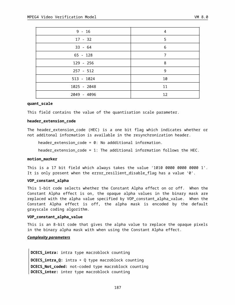
MPEG4 Video Verification Model VM 8.0
1111 110 8
1111 1110 9
1111 1111 0 10
1111 1111 10 11
1111 1111 110 12
Table 58 Variable length codes for DC size luminance
Vlc code DC size chrominance
00 0
01 1
10 2
110 3
1110 4
1111 0 5
1111 10 6
1111 110 7
1111 1110 8
1111 1111 0 9
1111 1111 10 10
1111 1111 110 11
1111 1111 1110 12
Table 59 Variable length codes for DC size chrominance
For each category additional bits are appended to the SIZE code to uniquely identify which difference in that category actually occurred (Table 60). The additional bits thus define the signed amplitude of the difference data. The number of additional bits (sign included) is equal to the SIZE value.
DIFFERENTIAL DC SIZE ADDITIONAL CODE
-4095 to -2048 12 000000000000 to 011111111111
-2047 to -1024 11 00000000000 to 01111111111
-1023 to -512 10 0000000000 to 0111111111
-511 to -256 9 000000000 to 011111111
-255 to -128 8 00000000 to 01111111
-127 to -64 7 0000000 to 0111111
-63 to -32 6 000000 to 011111
-31 to -16 5 00000 to 01111
-15 to -8 4 0000 to 0111
-7 to -4 3 000 to 011
187
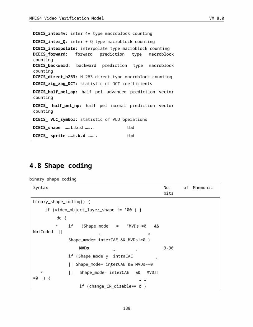
MPEG4 Video Verification Model VM 8.0
3 to -2 2 00 to 01
-1 1 0
0 0
1 1 1
2 to 3 2 10 to 11
4 to 7 3 100 to 111
8 to 15 4 1000 to 1111
16 to 31 5 10000 to 11111
32 to 63 6 100000 to 111111
64 to 127 7 1000000 to 1111111
128 to 255 8 10000000 to 11111111
256 to 511 9 100000000 to 111111111
512 to 1023 10 1000000000 to 1111111111
1024 to 2047 11 10000000000 to 11111111111
2048 to 4095 12 100000000000 to 111111111111
Table 60 Differential DC additional codes
The DC DCT coefficient is transmitted as a fixed length code of size bits_per_pixel if intra DC prediction is not used. If bits_per_pixel is greater than 8, a single extra bit with value ‘1’ is inserted after the first 8 bits are transmitted. This is done to avoid start code emulations. The code 0000 0000 is not used. The code 1000 0000 is not used, the reconstruction level of 1024 being coded as 1111 1111 (see Table 61).
If intra DC prediction is used, and the DC_size_luminance is greater than 8, an extra bit with value one is inserted after the first 8 bits of the additional code have been transmitted.
Index FLC Reconstruction level
into inverse transform
0 0000 0001 (1) 81 0000 0010 (2) 16
2 0000 0011 (3) 24
. . . .
. . . .
126 0111 1111 (127) 1016
127 1111 1111 (255) 1024
128 1000 0001 (129) 1032
. . . .
. . . .
252 1111 1101 (253) 2024
253 1111 1110 (254) 2032
Table 61 Reconstruction levels for INTRA-mode DC coefficient
188
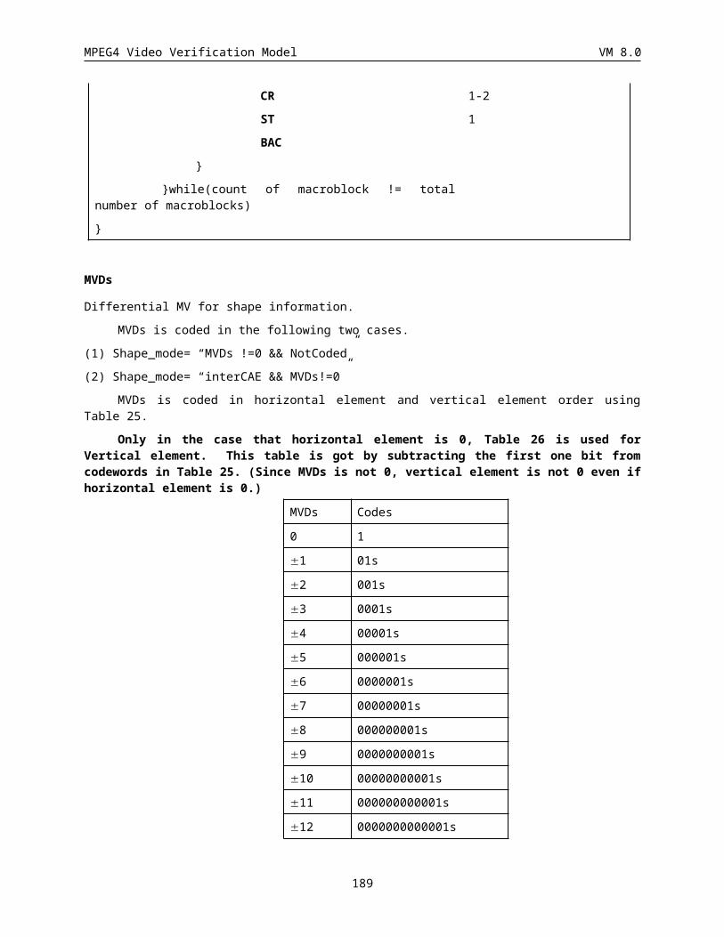
MPEG4 Video Verification Model VM 8.0
6.2.2 Transform coefficient (TCOEF) (Variable length)The most commonly occurring EVENTs for intra luminance blocks are coded with the variable length codes given in Table 62. The most common occurring EVENTs for intra chrominance and inter blocks are coded with the variable length codes given inTable 63, which is also used for coding of inter TCOEF.
This can be clearly summarized as follows.
· VLC table (Table 62) is used for coding of AC coefficients of intra luminance blocks.
· The TCOEF table (Table 63) used for coding of coefficients of inter blocks is also employed for coding of AC coefficients of intra chrominance blocks.
The last bit “s” denotes the sign of the level, “0” for positive and “1” for negative.
An EVENT is a combination of a last non-zero coefficient indication (LAST; “0”: there are more nonzero coefficients in this block, “1”: this is the last nonzero coefficient in this block), the number of successive zeros preceding the coded coefficient (RUN), and the non-zero value of the coded coefficient (LEVEL).
The remaining combinations of (LAST, RUN, LEVEL) are coded with a 22 bit word consisting of 7 bits ESCAPE, 1 bit LAST, 6 bits RUN and 8 bits LEVEL. Use of this 22-bit word for encoding the combinations listed in Table62 and Table 63 is not prohibited. For the 8-bit word for LEVEL, the codes 0000 0000 and 1000 0000 are not used. The codes for RUN and for LEVEL are given in Table 63.
6.2.3 Encoding of escape codeThe escape codes of DCT coefficients are encoded in three modes. The first mode is encoded by variable length codes after subtracting the LEVEL of an event with LMAX. LMAX is the maximum value of LEVEL specified in the VLC tables, with the same LAST and RUN as the event. The second mode is encoded by variable length codes after subtracting the RUN of an event with (RMAX+1). RMAX is the maximum value of RUN specified in the VLC tables, with the same LAST and LEVEL as the event. The third mode is encoded by fixed length codes (1-bit LAST, 6-bit RUN and 8-bit LEVEL) using Table 64. The first and second modes are respectively distinguished by “1” and “01” after the escape code. The third mode is identified by a “00” after the escape code. The encoding process is shown in Figure 73. LMAX values for I- and P-/B- VOPs are listed in Table 65 and Table 66 respectively. RMAX values for intra and inter VOP are listed in Table 67 and Table 68 respectively.
189
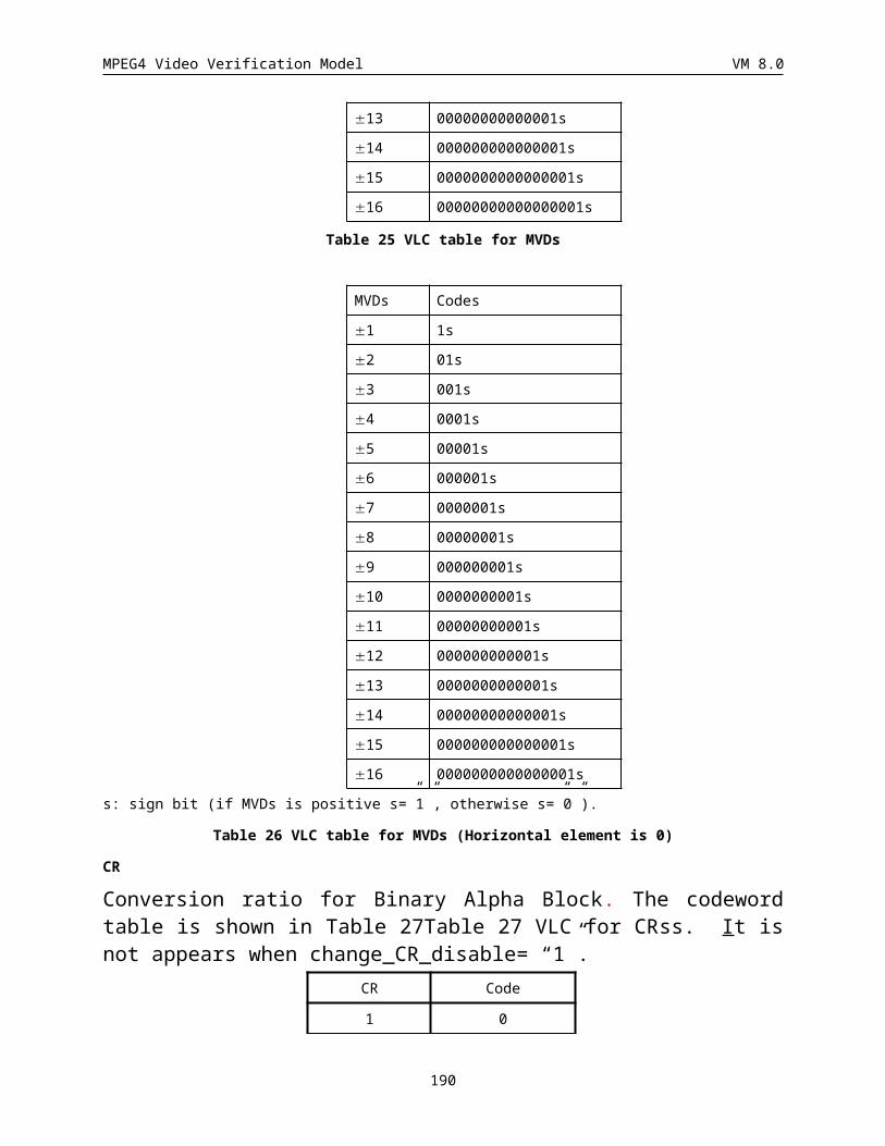
MPEG4 Video Verification Model VM 8.0
•LMAX : the maximum value of LEVEL of a given pair of (LAST, RUN)•RMAX : the maximum value of RUN of a given pair of (LAST, LEVEL)
VLC exists for(LAST, RUN, LEVEL)
?
Normal VLC
Compute (LAST, RUN, LEVEL+), where LEVEL+ = sign( LEVEL) x [ abs(LEVEL) - LMAX]
VLC exists for(LAST, RUN, LEVEL+)
?ESC + “1” + VLC
ESC + “00” + FLC
YES
NO
YES
NO
Compute (LAST, RUN+, LEVEL), where RUN + = RUN - (RMAX + 1)
VLC exists for(LAST, RUN+, LEVEL)
?ESC + “01” + VLC
YES
NO
12
3
45
6
78
9
Figure 73: Encoding of escape codes of DCT coefficients
index Last Run Level BITS VLC code Index Last Run Level BITS VLCode
0 0 0 1 3 10s 58 1 0 1 5 0111 s
1 0 0 3 5 1111 s 59 0 11 1 10 0000 1100 1s
2 0 0 6 7 0101 01s 60 1 0 6 12 0000 0000 101s
3 0 0 9 8 0010 111s 61 1 1 1 7 0011 11s
4 0 0 10 9 0001 1111 s 62 1 0 7 12 0000 0000 100s
5 0 0 13 10 0001 0010 1s 63 1 2 1 7 0011 10s
6 0 0 14 10 0001 0010 0s 64 0 5 1 7 0011 01s
7 0 0 17 11 0000 1000 01s
65 1 0 2 7 0011 00s
8 0 0 18 11 0000 1000 00s
66 1 5 1 8 0010 011s
9 0 0 21 12 0000 0000 111s
67 0 6 1 8 0010 010s
10 0 0 22 12 0000 0000 110s
68 1 3 1 8 0010 001s
11 0 0 23 12 0000 0100 000s
69 1 4 1 8 0010 000s
12 0 0 2 4 110s 70 1 9 1 9 0001 1010 s
13 0 1 2 7 0101 00s 71 0 8 1 9 0001 1001 s
14 0 0 11 9 0001 1110 s 72 0 9 1 9 0001 1000 s
15 0 0 19 11 0000 0011 11s
73 0 10 1 9 0001 0111 s
16 0 0 24 12 0000 0100 001s
74 1 0 3 9 0001 0110 s
190
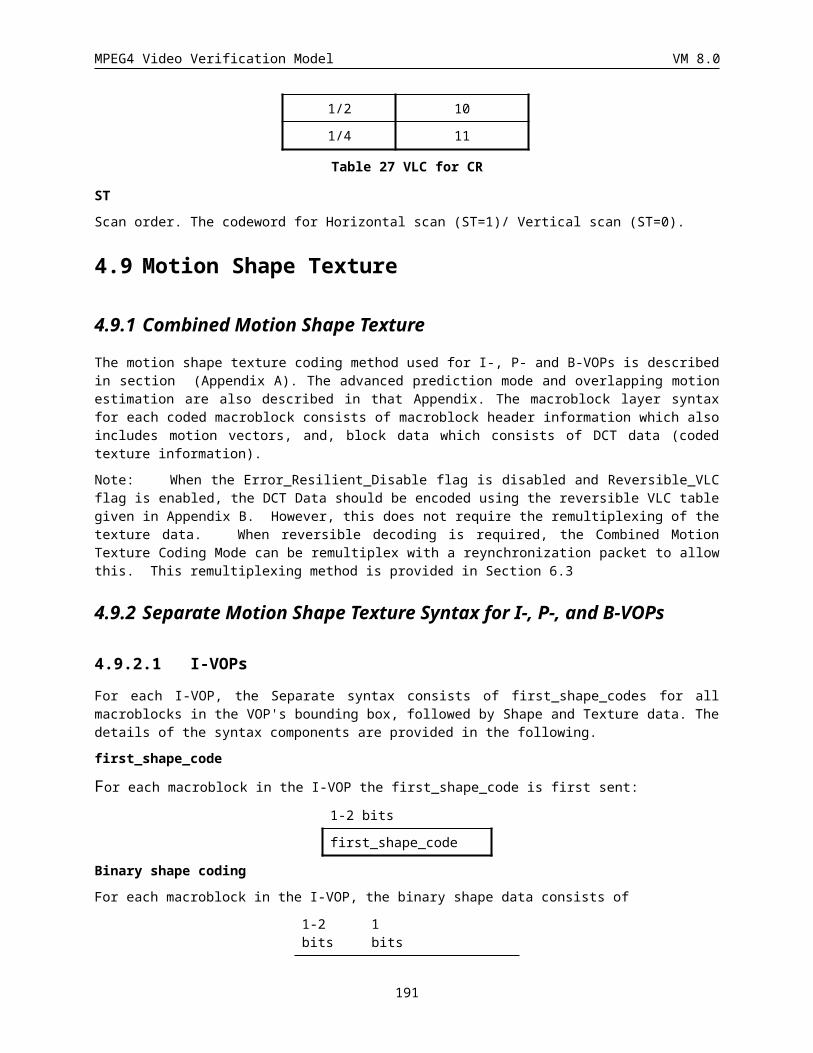
MPEG4 Video Verification Model VM 8.0
index Last Run Level BITS VLC code Index Last Run Level BITS VLCode
17 0 0 25 13 0000 0101 0000s
75 1 6 1 9 0001 0101 s
18 0 1 1 5 1110 s 76 1 7 1 9 0001 0100 s
19 0 0 12 9 0001 1101 s 77 1 8 1 9 0001 0011 s
20 0 0 20 11 0000 0011 10s
78 0 12 1 10 0000 1100 0s
21 0 0 26 13 0000 0101 0001s
79 1 0 4 10 0000 1011 1s
22 0 0 4 6 0110 1s 80 1 1 2 10 0000 1011 0s
23 0 0 15 10 0001 0001 1s 81 1 10 1 10 0000 1010 1s
24 0 1 7 11 0000 0011 01s
82 1 11 1 10 0000 1010 0s
25 0 0 5 6 0110 0s 83 1 12 1 10 0000 1001 1s
26 0 4 2 10 0001 0001 0s 84 1 13 1 10 0000 1001 0s
27 0 0 27 13 0000 0101 0010s
85 1 14 1 10 0000 1000 1s
28 0 2 1 6 0101 1s 86 0 13 1 11 0000 0001 11s
29 0 2 4 11 0000 0011 00s
87 1 0 5 11 0000 0001 10s
30 0 1 9 13 0000 0101 0011s
88 1 1 3 11 0000 0001 01s
31 0 0 7 7 0100 11s 89 1 2 2 11 0000 0001 00s
32 0 3 4 11 0000 0010 11s
90 1 3 2 12 0000 0100 100s
Index Last Run Level BITS VLC code Index Last Run Level BITS VLC code
33 0 6 3 13 0000 0101 0100s
91 1 4 2 12 0000 0100 101s34 0 0 8 7 0100 10s 92 1 15 1 12 0000 0100 110s
35 0 4 3 11 0000 0010 10s 93 1 16 1 12 0000 0100 111s
36 0 3 1 7 0100 01s 94 0 14 1 13 0000 0101 1000s
37 0 8 2 11 0000 0010 01s 95 1 0 8 13 0000 0101 1001s
38 0 4 1 7 0100 00s 96 1 5 2 13 0000 0101 1010s
39 0 5 3 11 0000 0010 00s 97 1 6 2 13 0000 0101 1011s
40 0 1 3 8 0010 110s 98 1 17 1 13 0000 0101 1100s
41 0 1 10 13 0000 0101 0101s
99 1 18 1 13 0000 0101 1101s
42 0 2 2 8 0010 101s 100 1 19 1 13 0000 0101 1110s
43 0 7 1 8 0010 100s 101 1 20 1 13 0000 0101 1111s
44 0 1 4 9 0001 1100 s 102 ESCAPE 7 0000 011
45 0 3 2 9 0001 1011 s
46 0 0 16 10 0001 0000 1s
47 0 1 5 10 0001 0000 0s
48 0 1 6 10 0000 1111 1s
49 0 2 3 10 0000 1111 0s
50 0 3 3 10 0000 1110 1s
51 0 5 2 10 0000 1110 0s
52 0 6 2 10 0000 1101 1s
53 0 7 2 10 0000 1101 0s
54 0 1 8 12 0000 0100 010s
55 0 9 2 12 0000 0100 011s
191
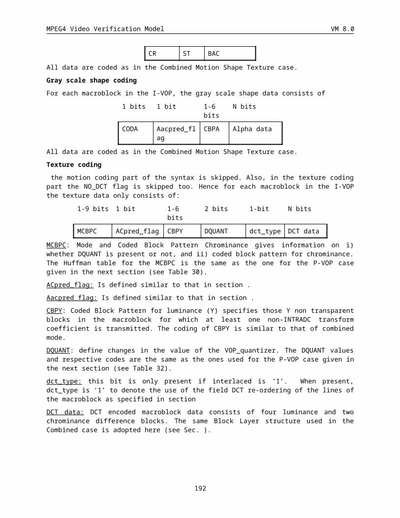
MPEG4 Video Verification Model VM 8.0
Index Last Run Level BITS VLC code Index Last Run Level BITS VLC code
56 0 2 5 13 0000 0101 0110s
57 0 7 3 13 0000 0101 0111s
Table 62 VLC table for INTRA Luminance TCOEF
Index Last Run Level BITS VLC code Index Last Run Level BITS VLC code
0 0 0 1 3 10s 58 1 0 1 5 0111 s
1 0 0 2 5 1111 s 59 1 0 2 10 0000 1100 1s
2 0 0 3 7 0101 01s 60 1 0 3 12 0000 0000 101s
3 0 0 4 8 0010 111s 61 1 1 1 7 0011 11s
4 0 0 5 9 0001 1111 s 62 1 1 2 12 0000 0000 100s
5 0 0 6 10 0001 0010 1s 63 1 2 1 7 0011 10s
6 0 0 7 10 0001 0010 0s 64 1 3 1 7 0011 01s
7 0 0 8 11 0000 1000 01s 65 1 4 1 7 0011 00s
8 0 0 9 11 0000 1000 00s 66 1 5 1 8 0010 011s
9 0 0 10 12 0000 0000 111s
67 1 6 1 8 0010 010s
10 0 0 11 12 0000 0000 110s
68 1 7 1 8 0010 001s
11 0 0 12 12 0000 0100 000s
69 1 8 1 8 0010 000s
12 0 1 1 4 110s 70 1 9 1 9 0001 1010 s
13 0 1 2 7 0101 00s 71 1 10 1 9 0001 1001 s
14 0 1 3 9 0001 1110 s 72 1 11 1 9 0001 1000 s
15 0 1 4 11 0000 0011 11s 73 1 12 1 9 0001 0111 s
16 0 1 5 12 0000 0100 001s
74 1 13 1 9 0001 0110 s
17 0 1 6 13 0000 0101 0000s
75 1 14 1 9 0001 0101 s
18 0 2 1 5 1110 s 76 1 15 1 9 0001 0100 s
19 0 2 2 9 0001 1101 s 77 1 16 1 9 0001 0011 s
20 0 2 3 11 0000 0011 10s 78 1 17 1 10 0000 1100 0s
21 0 2 4 13 0000 0101 0001s
79 1 18 1 10 0000 1011 1s
22 0 3 1 6 0110 1s 80 1 19 1 10 0000 1011 0s
23 0 3 2 10 0001 0001 1s 81 1 20 1 10 0000 1010 1s
24 0 3 3 11 0000 0011 01s 82 1 21 1 10 0000 1010 0s
25 0 4 1 6 0110 0s 83 1 22 1 10 0000 1001 1s
26 0 4 2 10 0001 0001 0s 84 1 23 1 10 0000 1001 0s
27 0 4 3 13 0000 0101 0010s
85 1 24 1 10 0000 1000 1s
28 0 5 1 6 0101 1s 86 1 25 1 11 0000 0001 11s
192
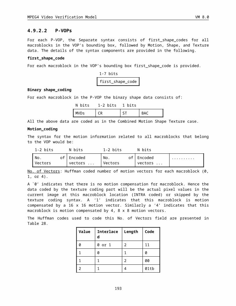
MPEG4 Video Verification Model VM 8.0
Index Last Run Level BITS VLC code Index Last Run Level BITS VLC code
29 0 5 2 11 0000 0011 00s 87 1 26 1 11 0000 0001 10s
30 0 5 3 13 0000 0101 0011s
88 1 27 1 11 0000 0001 01s
31 0 6 1 7 0100 11s 89 1 28 1 11 0000 0001 00s
32 0 6 2 11 0000 0010 11s 90 1 29 1 12 0000 0100 100s
33 0 6 3 13 0000 0101 0100s
91 1 30 1 12 0000 0100 101s
34 0 7 1 7 0100 10s 92 1 31 1 12 0000 0100 110s
35 0 7 2 11 0000 0010 10s 93 1 32 1 12 0000 0100 111s
36 0 8 1 7 0100 01s 94 1 33 1 13 0000 0101 1000s
37 0 8 2 11 0000 0010 01s 95 1 34 1 13 0000 0101 1001s
38 0 9 1 7 0100 00s 96 1 35 1 13 0000 0101 1010s
39 0 9 2 11 0000 0010 00s 97 1 36 1 13 0000 0101 1011s
40 0 10 1 8 0010 110s 98 1 37 1 13 0000 0101 1100s
41 0 10 2 13 0000 0101 0101s
99 1 38 1 13 0000 0101 1101s
42 0 11 1 8 0010 101s 100 1 39 1 13 0000 0101 1110s
43 0 12 1 8 0010 100s 101 1 40 1 13 0000 0101 1111s
44 0 13 1 9 0001 1100 s 102 ESCAPE 7 0000 011
45 0 14 1 9 0001 1011 s
46 0 15 1 10 0001 0000 1s
47 0 16 1 10 0001 0000 0s
48 0 17 1 10 0000 1111 1s
49 0 18 1 10 0000 1111 0s
50 0 19 1 10 0000 1110 1s
51 0 20 1 10 0000 1110 0s
52 0 21 1 10 0000 1101 1s
53 0 22 1 10 0000 1101 0s
54 0 23 1 12 0000 0100 010s
55 0 24 1 12 0000 0100 011s
56 0 25 1 13 0000 0101 0110s
57 0 26 1 13 0000 0101 0111s
Table 63 VLC table for Intra Chrominance and Inter Lumimance and Chrominance TCOEF
193
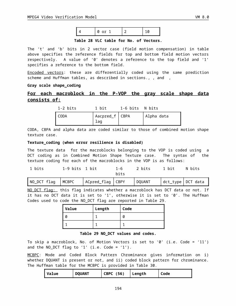
MPEG4 Video Verification Model VM 8.0
Index Run Code Index Level Code
0 0 000 000 - -128 FORBIDDEN
1 1 000 001 0 -127 1000 00012 2 000 010 . . .. . . 125 -2 1111 1110. . . 126 -1 1111 111163 63 111 111 - 0 FORBIDDEN
127 1 0000 0001128 2 0000 0010. . .253 127 0111 1111
Table 64 FLC table for RUNS and LEVELS
This annex provides tables for value of LMAX and RMAX for decoding escape codes of DCT coefficients.
Table 65: LMAX values of I-VOP
LAST RUN LMAX LAST RUN LMAX
0 0 27 1 0 8
0 1 10 1 1 3
0 2 5 1 2-6 2
0 3 4 1 7-20 1
0 4-7 3 1 others N/A
0 8-9 2
0 10-14 1
0 others N/A
Table 66: LMAX values of P- or B-VOP
LAST RUN LMAX LAST RUN LMAX
0 0 12 1 0 3
0 1 6 1 1 2
0 2 4 1 2-40 1
0 3-6 3 1 others N/A
0 7-10 2
0 11-26 1
0 others N/A
194
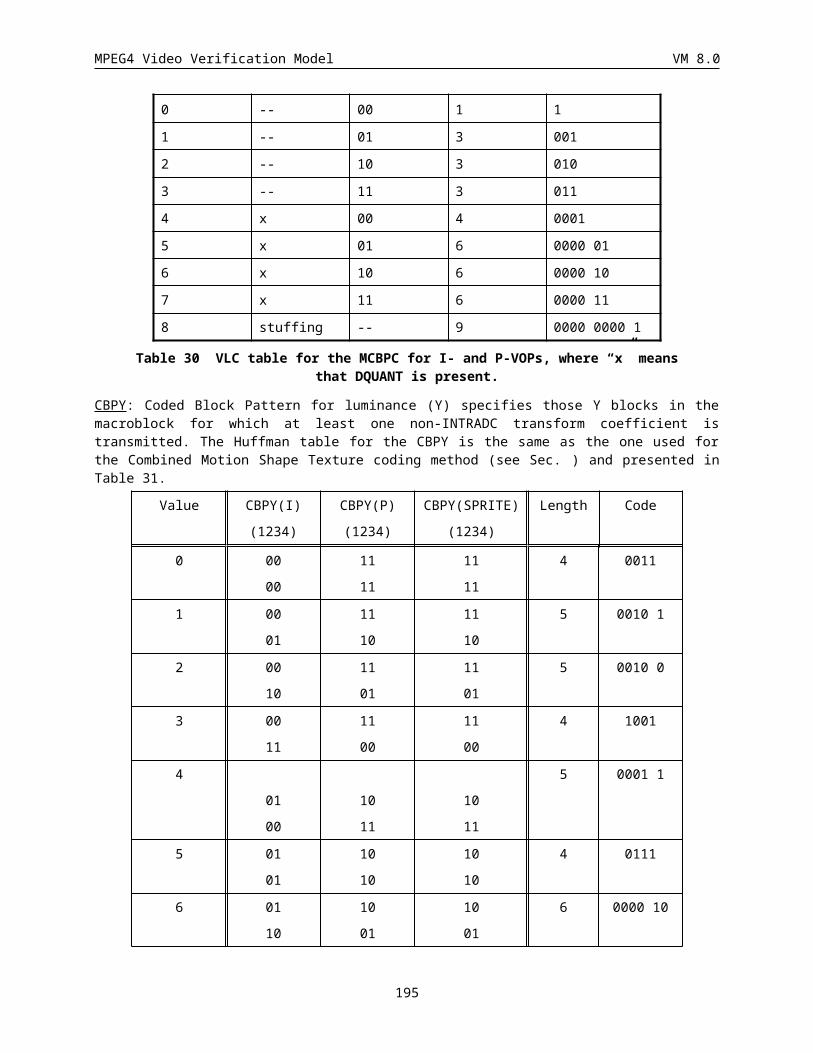
MPEG4 Video Verification Model VM 8.0
Table 67: RMAX values of I-VOP
LAST LEVEL RMAX LAST LEVEL RMAX
0 1 14 1 1 20
0 2 9 1 2 6
0 3 7 1 3 1
0 4 3 1 4-8 0
0 5 2 1 others N/A
0 6-10 1
0 11-27 0
0 others N/A
Table 68: RMAX values of P- or B-VOP
LAST LEVEL RMAX LAST LEVEL RMAX
0 1 26 1 1 40
0 2 10 1 2 1
0 3 6 1 3 0
0 4 2 1 others N/A
0 5-6 1
0 7-12 0
0 others N/A
6.3 Remultiplexing of Combined Motion Texture Coding Mode for Error Resilience
This section describes two modes for the combined motion texture coding which allows the utilization of the data partitioning and Reversible VLCs for improving the error resilience performance of the Video Verification Model.
Data Partitioning Mode
This mode uses the same syntactic elements defined in the Combined Texture Coding Mode with reordering. For each resynchronization packet, in a P-VOP the DCT coefficients, motion data and the header information are reordered as shown below
17 bits 1-12 bits
5 bits 1 or 12 bits
M bits 17 bits N bits 17 bits
RM MBA QP HEC Motion Data Motion Marker Texture Data RM
where, as discussed in section XXX,
RM: Resynchronization Marker as defined in Section XXX and further in Section (0000 0000 0000 0000 1),
195
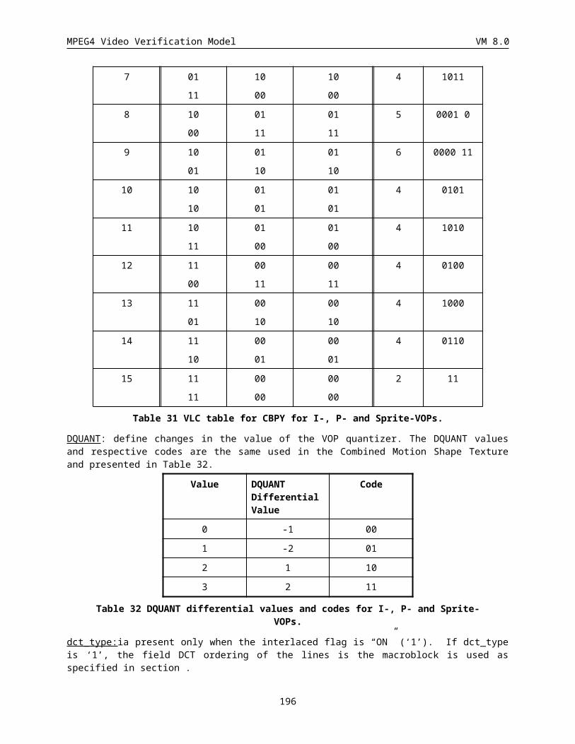
MPEG4 Video Verification Model VM 8.0
MBA: Macroblock Address as defined in Section XXX and further in Section ,
QP: Quantization Parameter as defined in Section XXX and further in Section ,
HEC: Header Extension Code as defined in Section XXX and further in Section .
Motion Data: The motion data is further rearranged as follows,
COD MCBPC MV1-4 COD MCBPC MV1-4 COD Motion Marker
MB( k) MB( k) MB( k) MB( k+1) MB( k+1) MB( k+1) MB( k+2) ......
COD MB(k): This flag indicates whether a macroblock has DCT data or not. If it has no DCT data it is set to ‘1’, otherwise it is set to ‘0’. The Huffman Codes used to code the NO_DCT flag are the same as the one for the P-VOP case given in the non error resilient case earlier in this section.
MCBPC MB(k): Mode and Coded Block Pattern Chrominance gives information on i) whether DQUANT is present or not, and ii) coded block pattern for chrominance. The Huffman table for the MCBPC is the same as the one for the P-VOP case given in the non error resilient case earlier in this section.
MV1-4 MB(k): The 16x16 to 8x8 motion vectors for the macroblock MB(k)
Motion Marker: This is a 17-bit word that is unique from any valid combination of the VLC data that occurs before it. Its value is 1111 1000 0000 0000 1.
Texture Data: The DCT data is further rearranged as follows,
CBPY DQUANT (optional)
CBPY DQUANT (optional)
DCT DCT
MB( k) MB( k) MB( k+1) MB( k+1) MB( k) MB( k+1)
CBPY MB(k): Coded Block Pattern for luminance (Y) specifies those Y non transparent blocks in the macroblock for which at least one non-INTRADC transform coefficient is transmitted. The coding of CBPY is the same as the one for the P-VOP case given in the non error resilient case earlier in this section.
DQUANT: define changes in the value of the VOP_quantizer. The DQUANT values and respective codes are the same as the one for the P-VOP case given in the non error resilient case earlier in this section.
DCT data: The DCT encoded macroblock data consists of four luminance and two chrominance difference blocks.
Reversible VLCs
When this mode is enabled, a Reversible VLC (RVLC) table shown in Table is used to code the DCT coefficients.
196
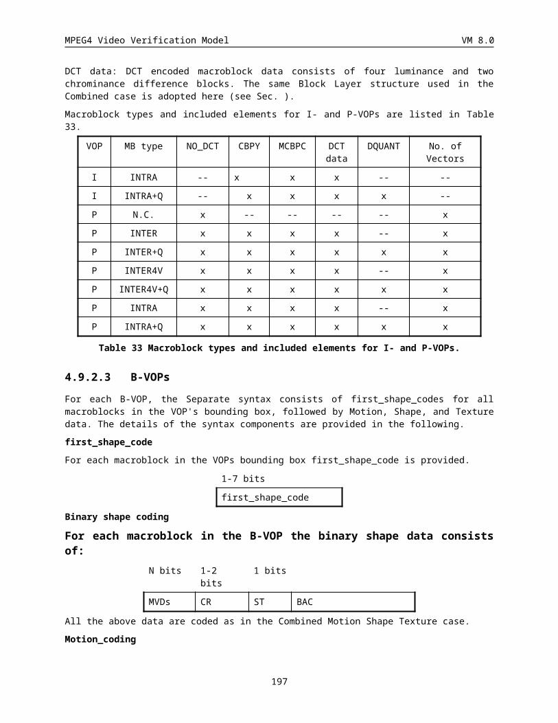
MPEG4 Video Verification Model VM 8.0
7 APPENDIX B: TRANSFORM COEFFICIENT (TCOFF) (VARIABLE LENGTH)
ESCAPE code is added at the beginning and the end of these fixed-length codes for realizing two-way decode as shown in Figure 74.
ESCAPE LAST RUN LEVEL ESCAPE
Figure 74 FLC Format of TCOEF
Note: There are two types for ESCAPE added at the end of these fixed-length codes, and codewords are “0000s”.
S=0 : LEVEL is positive
S=1 : LEVEL is negative
INTRA INTER
INDEX LAST RUN LEVEL LAST RUN LEVEL BITS VLC_CODE
0 0 0 1 0 0 1 4 110s
1 0 0 2 0 1 1 4 111s
2 0 1 1 0 0 2 5 0001s
3 0 0 3 0 2 1 5 1010s
4 1 0 1 1 0 1 5 1011s
5 0 2 1 0 0 3 6 00100s
6 0 3 1 0 3 1 6 00101s
7 0 1 2 0 4 1 6 01000s
8 0 0 4 0 5 1 6 01001s
9 1 1 1 1 1 1 6 10010s
10 1 2 1 1 2 1 6 10011s
11 0 4 1 0 1 2 7 001100s
12 0 5 1 0 6 1 7 001101s
13 0 0 5 0 7 1 7 010100s
14 0 0 6 0 8 1 7 010101s
15 1 3 1 1 3 1 7 011000s
16 1 4 1 1 4 1 7 011001s
17 1 5 1 1 5 1 7 100010s
18 1 6 1 1 6 1 7 100011s
19 0 6 1 0 0 4 8 0011100s
20 0 7 1 0 2 2 8 0011101s
21 0 2 2 0 9 1 8 0101100s
22 0 1 3 0 10 1 8 0101101s
23 0 0 7 0 11 1 8 0110100s
24 1 7 1 1 7 1 8 0110101s
25 1 8 1 1 8 1 8 0111000s
197
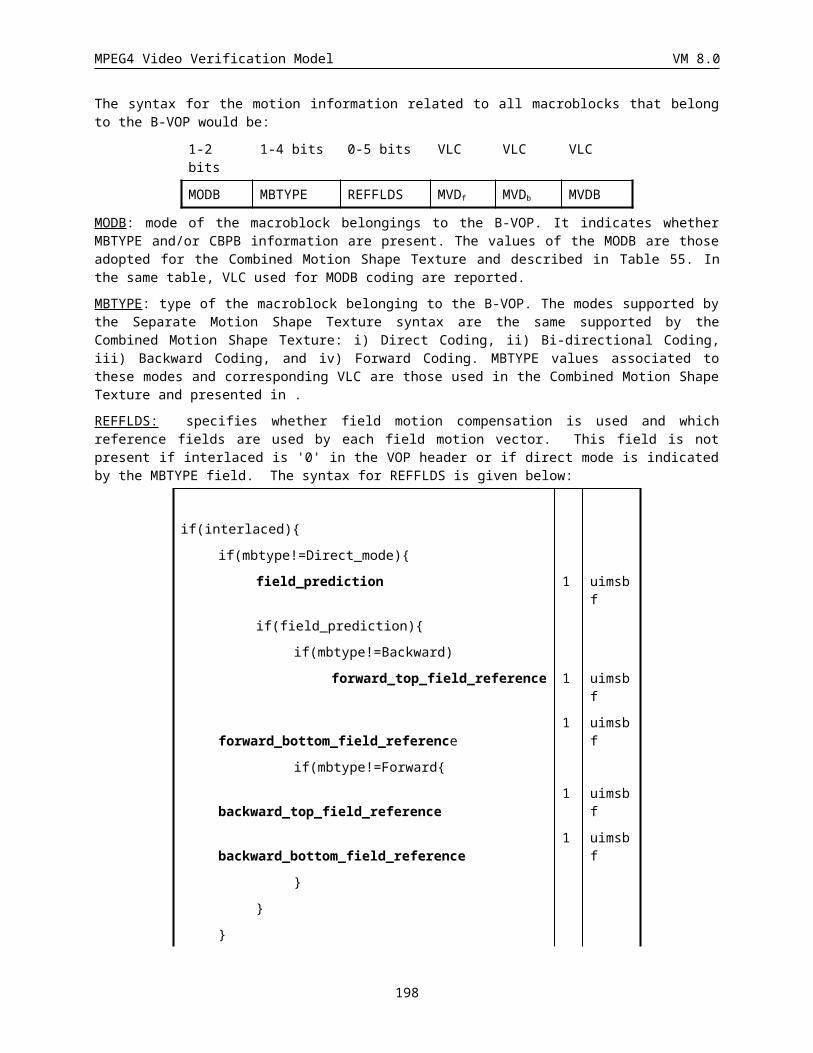
MPEG4 Video Verification Model VM 8.0
26 1 9 1 1 9 1 8 0111001s
27 1 10 1 1 10 1 8 1000010s
28 1 11 1 1 11 1 8 1000011s
29 0 8 1 0 0 5 9 00111100s
30 0 9 1 0 0 6 9 00111101s
31 0 3 2 0 1 3 9 01011100s
32 0 4 2 0 3 2 9 01011101s
33 0 1 4 0 4 2 9 01101100s
34 0 1 5 0 12 1 9 01101101s
35 0 0 8 0 13 1 9 01110100s
36 0 0 9 0 14 1 9 01110101s
37 1 0 2 1 0 2 9 01111000s
38 1 12 1 1 12 1 9 01111001s
39 1 13 1 1 13 1 9 10000010s
40 1 14 1 1 14 1 9 10000011s
41 0 10 1 0 0 7 10 001111100s
42 0 5 2 0 1 4 10 001111101s
43 0 2 3 0 2 3 10 010111100s
44 0 3 3 0 5 2 10 010111101s
45 0 1 6 0 15 1 10 011011100s
46 0 0 10 0 16 1 10 011011101s
47 0 0 11 0 17 1 10 011101100s
48 1 1 2 1 1 2 10 011101101s
49 1 15 1 1 15 1 10 011110100s
50 1 16 1 1 16 1 10 011110101s
51 1 17 1 1 17 1 10 011111000s
52 1 18 1 1 18 1 10 011111001s
53 1 19 1 1 19 1 10 100000010s
54 1 20 1 1 20 1 10 100000011s
55 0 11 1 0 0 8 11 0011111100s
56 0 12 1 0 0 9 11 0011111101s
57 0 6 2 0 1 5 11 0101111100s
58 0 7 2 0 3 3 11 0101111101s
59 0 8 2 0 6 2 11 0110111100s
60 0 4 3 0 7 2 11 0110111101s
61 0 2 4 0 8 2 11 0111011100s
62 0 1 7 0 9 2 11 0111011101s
63 0 0 12 0 18 1 11 0111101100s
64 0 0 13 0 19 1 11 0111101101s
65 0 0 14 0 20 1 11 0111110100s
66 1 21 1 1 21 1 11 0111110101s
198
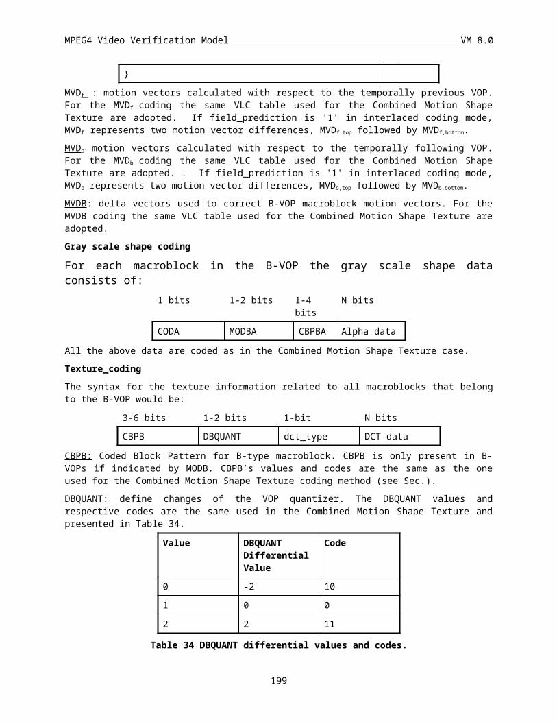
MPEG4 Video Verification Model VM 8.0
67 1 22 1 1 22 1 11 0111111000s
68 1 23 1 1 23 1 11 0111111001s
69 1 24 1 1 24 1 11 1000000010s
70 1 25 1 1 25 1 11 1000000011s
71 0 13 1 0 0 10 12 00111111100s
72 0 9 2 0 0 11 12 00111111101s
73 0 5 3 0 1 6 12 01011111100s
74 0 6 3 0 2 4 12 01011111101s
75 0 7 3 0 4 3 12 01101111100s
76 0 3 4 0 5 3 12 01101111101s
77 0 2 5 0 10 2 12 01110111100s
78 0 2 6 0 21 1 12 01110111101s
79 0 1 8 0 22 1 12 01111011100s
80 0 1 9 0 23 1 12 01111011101s
81 0 0 15 0 24 1 12 01111101100s
82 0 0 16 0 25 1 12 01111101101s
83 0 0 17 0 26 1 12 01111110100s
84 1 0 3 1 0 3 12 01111110101s
85 1 2 2 1 2 2 12 01111111000s
86 1 26 1 1 26 1 12 01111111001s
87 1 27 1 1 27 1 12 10000000010s
88 1 28 1 1 28 1 12 10000000011s
89 0 10 2 0 0 12 13 001111111100s
90 0 4 4 0 1 7 13 001111111101s
91 0 5 4 0 2 5 13 010111111100s
92 0 6 4 0 3 4 13 010111111101s
93 0 3 5 0 6 3 13 011011111100s
94 0 4 5 0 7 3 13 011011111101s
95 0 1 10 0 11 2 13 011101111100s
96 0 0 18 0 27 1 13 011101111101s
97 0 0 19 0 28 1 13 011110111100s
98 0 0 22 0 29 1 13 011110111101s
99 1 1 3 1 1 3 13 011111011100s
100 1 3 2 1 3 2 13 011111011101s
101 1 4 2 1 4 2 13 011111101100s
102 1 29 1 1 29 1 13 011111101101s
103 1 30 1 1 30 1 13 011111110100s
104 1 31 1 1 31 1 13 011111110101s
105 1 32 1 1 32 1 13 011111111000s
106 1 33 1 1 33 1 13 011111111001s
107 1 34 1 1 34 1 13 100000000010s
199
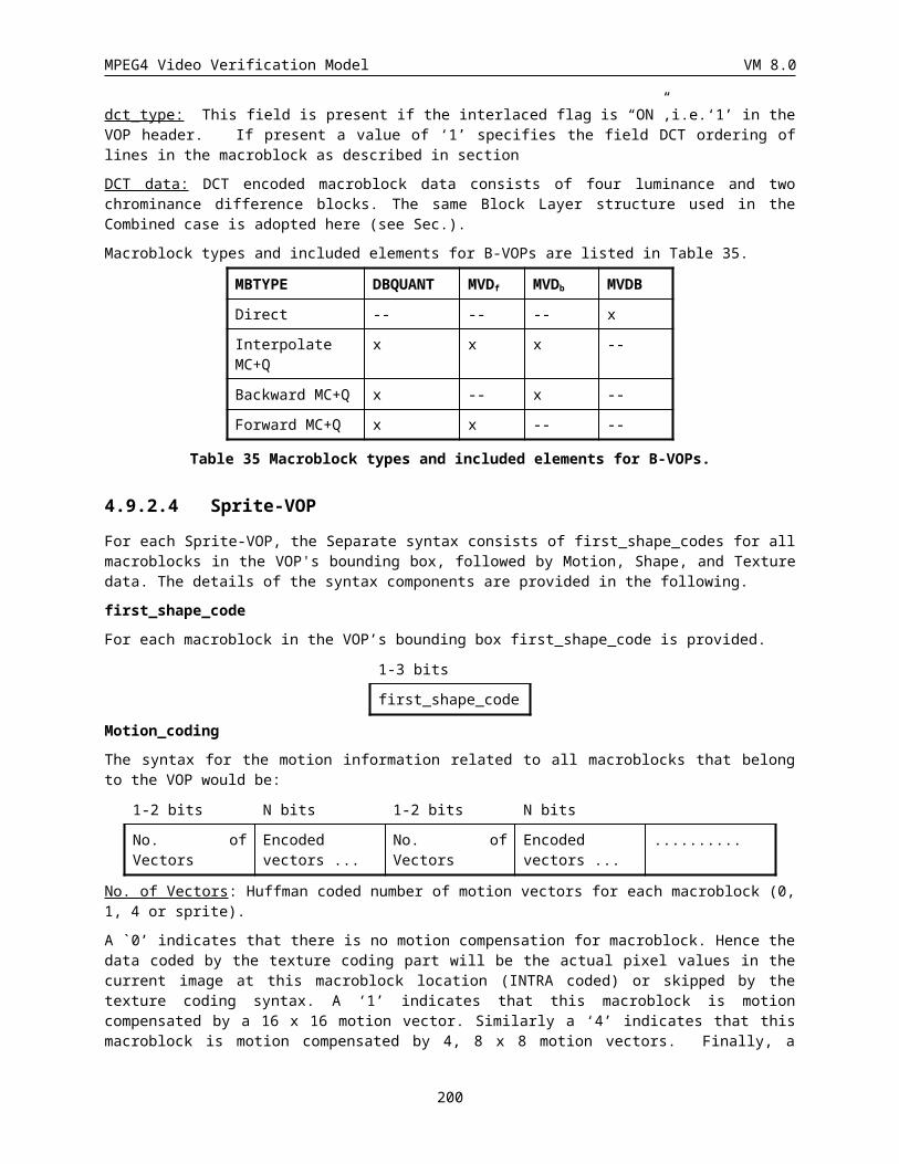
MPEG4 Video Verification Model VM 8.0
108 1 35 1 1 35 1 13 100000000011s
109 0 14 1 0 0 13 14 0011111111100s
110 0 15 1 0 0 14 14 0011111111101s
111 0 11 2 0 0 15 14 0101111111100s
112 0 8 3 0 0 16 14 0101111111101s
113 0 9 3 0 1 8 14 0110111111100s
114 0 7 4 0 3 5 14 0110111111101s
115 0 3 6 0 4 4 14 0111011111100s
116 0 2 7 0 5 4 14 0111011111101s
117 0 2 8 0 8 3 14 0111101111100s
118 0 2 9 0 12 2 14 0111101111101s
119 0 1 11 0 30 1 14 0111110111100s
120 0 0 20 0 31 1 14 0111110111101s
121 0 0 21 0 32 1 14 0111111011100s
122 0 0 23 0 33 1 14 0111111011101s
123 1 0 4 1 0 4 14 0111111101100s
124 1 5 2 1 5 2 14 0111111101101s
125 1 6 2 1 6 2 14 0111111110100s
126 1 7 2 1 7 2 14 0111111110101s
127 1 8 2 1 8 2 14 0111111111000s
128 1 9 2 1 9 2 14 0111111111001s
129 1 36 1 1 36 1 14 1000000000010s
130 1 37 1 1 37 1 14 1000000000011s
131 0 16 1 0 0 17 15 00111111111100s
132 0 17 1 0 0 18 15 00111111111101s
133 0 18 1 0 1 9 15 01011111111100s
134 0 8 4 0 1 10 15 01011111111101s
135 0 5 5 0 2 6 15 01101111111100s
136 0 4 6 0 2 7 15 01101111111101s
137 0 5 6 0 3 6 15 01110111111100s
138 0 3 7 0 6 4 15 01110111111101s
139 0 3 8 0 9 3 15 01111011111100s
140 0 2 10 0 13 2 15 01111011111101s
141 0 2 11 0 14 2 15 01111101111100s
142 0 1 12 0 15 2 15 01111101111101s
143 0 1 13 0 16 2 15 01111110111100s
144 0 0 24 0 34 1 15 01111110111101s
145 0 0 25 0 35 1 15 01111111011100s
146 0 0 26 0 36 1 15 01111111011101s
147 1 0 5 1 0 5 15 01111111101100s
148 1 1 4 1 1 4 15 01111111101101s
200
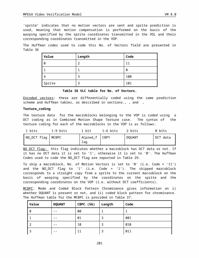
MPEG4 Video Verification Model VM 8.0
149 1 10 2 1 10 2 15 01111111110100s
150 1 11 2 1 11 2 15 01111111110101s
151 1 12 2 1 12 2 15 01111111111000s
152 1 38 1 1 38 1 15 01111111111001s
153 1 39 1 1 39 1 15 10000000000010s
154 1 40 1 1 40 1 15 10000000000011s
155 0 0 27 0 0 19 16 001111111111100s
156 0 3 9 0 3 7 16 001111111111101s
157 0 6 5 0 4 5 16 010111111111100s
158 0 7 5 0 7 4 16 010111111111101s
159 0 9 4 0 17 2 16 011011111111100s
160 0 12 2 0 37 1 16 011011111111101s
161 0 19 1 0 38 1 16 011101111111100s
162 1 1 5 1 1 5 16 011101111111101s
163 1 2 3 1 2 3 16 011110111111100s
164 1 13 2 1 13 2 16 011110111111101s
165 1 41 1 1 41 1 16 011111011111100s
166 1 42 1 1 42 1 16 011111011111101s
167 1 43 1 1 43 1 16 011111101111100s
168 1 44 1 1 44 1 16 011111101111101s
169 ESCAPE 5 0000s
Table 69 RVLC table for TCOF
RUN CODE
0 000000
1 000001
2 000010
: :
63 111111
Table 70 FLC table for RUN
LEVEL CODE
0 FORBIDDEN
1 0000001
2 0000010
: :
127 1111111
Table 71 FLC table for LEVEL
201
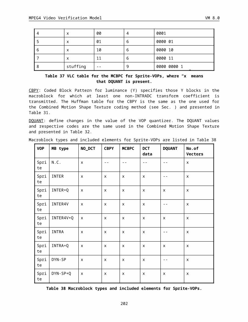
MPEG4 Video Verification Model VM 8.0
8 APPENDIX C: DEFINITION OF POST- FILTER
The post-filter is composed of deblocking filter and deringing filter, described below. It was temporarily decided that the deblocking filter is applied first and then the deringing filter.
8.1 Deblocking filterThe filter operations are performed along the 8x8 block edges at the decoder as a post-processing operation. Luminance as well as chrominace data is filtered. The figure shows the block boundaries.
v0 v1 v2 v3 v4 v5 v6 v7
v0
v1
v2
v3
v4
v5
v6
v7
Block boundary
Block boundary
S0
S0
S1
S2
S1 S2
v8 v9
v8
v9
Pixels for filtering on a
vertical edge
Pixels for filtering on a
horizontal edge
In the filter operations, two modes are used separately depending on the pixel conditions around a boundary. The following procedure is used to find a very smooth region with blocking artifacts due to small dc offset and to assign it a DC offset mode. In the other case, default mode operations are applied.
eq_cnt = f(v0v1) + f(v1v2) + f(v2v3) + f(v3v4) + f(v4v5) + f(v5v6) + f(v6v7)
+ f(v7v8) + f(v8v9),
where f(g ) = 1 if |g | THR1 and 0 otherwise.
If (eq_cnt ³ THR2)
DC offset mode is applied,
else
Default mode is applied.
For the simulation, threshold values of THR1 = 2 and THR2 = 6 are used.
In the default mode, a signal adaptive smoothing scheme is applied by differentiating image details at the block discontinuities using the frequency information of neighbor pixel arrays, S0, S1, and S2,. The filtering scheme in default mode is executed by replacing the boundary pixel values v4 and v5 with v4 and v5 as follows:
v4 = v4d,
v5 = v5+d,
202

MPEG4 Video Verification Model VM 8.0
and d = CLIP(5(a3,0 a3,0)//8, 0, (v4v5)/2) d(|a3,0| < QP)
where a3,0 = SIGN(a3,0) MIN(|a3,0|, |a3,1|, |a3,2|).
Frequency components a3,0, a3,1, and a3,2 can be evaluated from the simple inner product of the approximated DCT kernel [2 -5 5 -2] with the pixel vectors, i.e.,
a3,0 = ([2 -5 5 -2] · [v3 v4 v5 v6]T ) // 8,
a3,1 = ([2 -5 5 -2] · [v1 v2 v3 v4]T ) // 8,
a3,2 = ([2 -5 5 -2] · [v5 v6 v7 v8]T ) // 8.
Here CLIP(x,p,q) clips x to a value between p and q; and QP denotes the quantization parameter of the macroblock where pixel v5 belongs. d(condition)=1 if the "condition" is true and 0 otherwise..
In very smooth region, the filtering in the default mode is not good enough to reduce the blocking artifact due to dc offset. So we treat this case in the DC offset mode and apply a stronger smoothing filter as follows :
max = MAX (v1, v2, v3, v4, v5, v6, v7, v8),
min = MIN (v1, v2, v3, v4, v5, v6, v7, v8),
if ( |maxmin| < 2QP ) {
16//}1,1,2,2,4,2,2,1,1{}44:{8
811
,:?,
,:?
81,
8998
1001
4
4
kbm
mm
ififif
vvQP<vvv
vvQP<vvp
npbv
k
mm
knk
kn
}
else
No change will be done.
The above filter operations are applied for all the block boundaries first along the horizontal edges followed by the vertical edges. If a pixel value is changed by the previous filtering operation, the updated pixel value is used for the next filtering.
8.2 Deringing filterThis filter comprises three subprocesses; threshold determination, index acquisition and adaptive smoothing. This filter is applied to the pixels on 8x8 block basis. More specifically 8x8 pixels are processed by referencing 10x10 pixels at each block. The following notation is used to specify the six blocks in a macroblock. For instance, block[5] corresponds to the Cb block whereas block[k] is used as a general representation in the following sections.
203
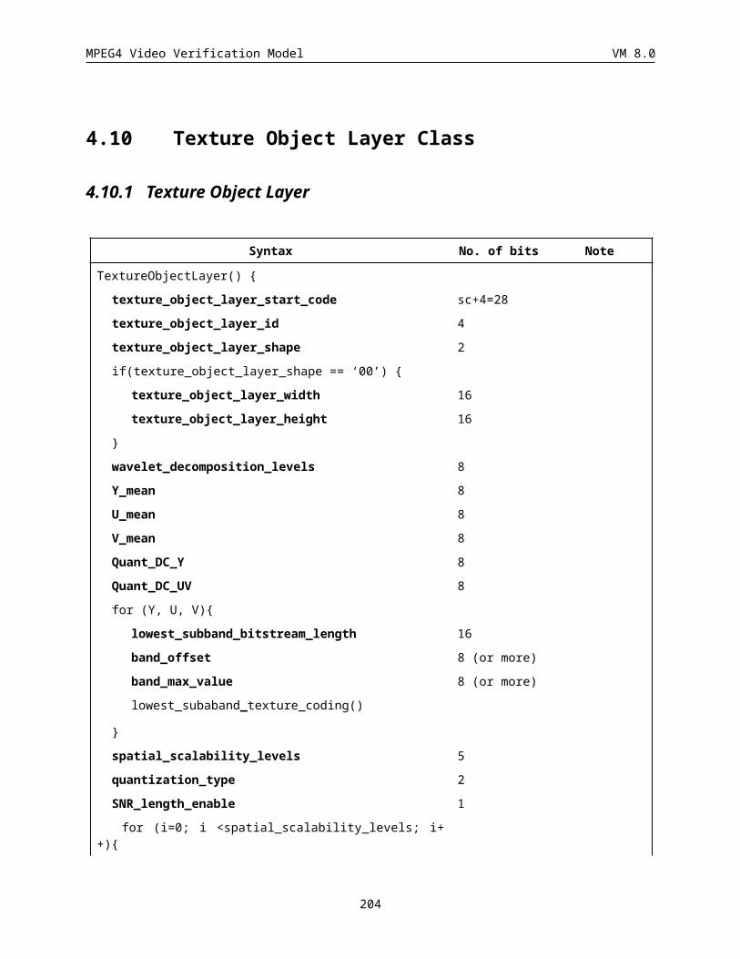
MPEG4 Video Verification Model VM 8.0
8.2.1 Threshold determination Firstly, calculate maximum and minimum gray value within a block in the decoded image. Secondary, the threshold denoted by thr[k] and the dynamic range of gray scale denoted by range[k] are set:
thr k imum k imum k[ ] max [ ] min [ ] / 1 2
range k imum k imum k[ ] max [ ] min [ ]
An additional process is done only for the luminance blocks. Let max_range be the maximum value of the dynamic range among four luminance blocks.
max_ [ ]maxrange range k
Then apply the rearrangement as follows.
for( k=1 ; k<5 ; k++ ){
if( range[k] < 32 && max_range > =64 )
thr[k] = thr[kmax];
if( max_range<16 )
thr[k] = 0;
}
8.2.2 Index acquisitionOnce the threshold value is determined, the remaining operations are purely 8x8 block basis. Let rec(h,v) and bin(h,v) be the gray value at coordinates (h,v) where h,v=0,1,2,...,7, and the corresponding binary index, respectively. Then bin(h,v) can be obtained by:
otherwise
thrvhrecifvhbin
³
,
01
,
Note that (h,v) is use to address a pixel in a block, while (i,j) is for accessing a pixel in a 3x3 window.
8.2.3 Adaptive smoothing
8.2.3.1 Adaptive filteringThe figure below is the binary indices in 8x8 block level, whereas practically 10x10 binary indices are calculated to process one 8x8 block.
0 0 0 0 0 0 0 0 0 0
0 0 0 0 0 0 0 0 0 0
204
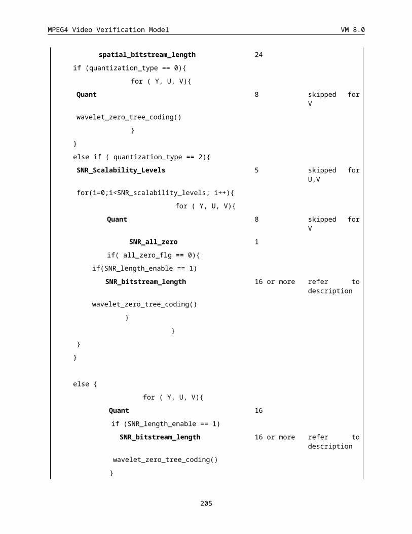
MPEG4 Video Verification Model VM 8.0
1 0 0 0 0 0 0 0 1 1
1 1 0 0 0 0 0 1 1 1
1 1 1 0 0 0 1 1 1 1
1 1 1 1 1 1 1 1 1 1
1 1 1 1 1 1 1 1 1 1
1 1 1 1 1 1 1 1 1 1
1 1 1 1 1 1 1 1 1 0
1 1 1 1 1 1 1 1 0 0
Figure 75: Example of adaptive filtering and binary index
The filter is applied only if the binary indices in a 3x3 window are all the same, i.e., all “0” indices or all “1” indices. Note 10x10 binary indices are obtained with a single threshold which corresponds to the 8x8 block shown in the above figure, where the shaded region represents the pixels to be filtered.
.
The filter coefficients used for both intra and non-intra blocks denoted by coef(i,j), where i,j=-1,0,1, are:
1 2 1
2 4 2
1 2 1
Figure 76: Filter mask for adaptive smoothing
Here the coefficient at the center pixel, i.e., coef(0,0), corresponds to the pixel to be filtered. The filter output flt’(i,j) is obtained by:
16//,,8,'1
1
1
1
i j
jvihrecjicoefvhflt
8.2.3.2 ClippingThe maximum gray level change between the reconstructed pixel and the filtered one is limited according to the quantization parameter, i.e., QP. Let flt(h,v) and flt’(h,v) be the filtered pixel value and the pixel value before limitation, respectively.
if( flt’(h,v) - rec(h,v) > max_diff )
flt(h,v) = rec(h,v) + max_diff
else if( flt’(h,v) - rec(h,v) < -max_diff )
flt(h,v) = rec(h,v) - max_diff
else
flt(h,v) = flt’(h,v)
205
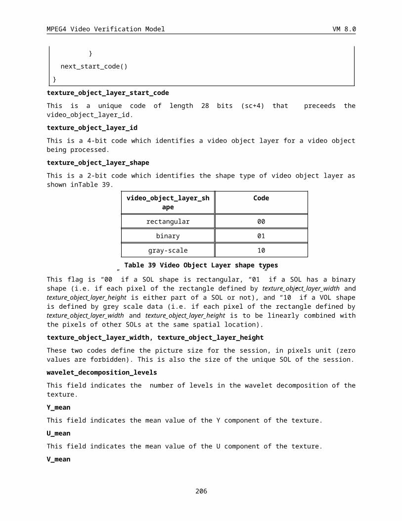
MPEG4 Video Verification Model VM 8.0
where max_diff=QP/2 for both intra and inetr macroblocks.
206
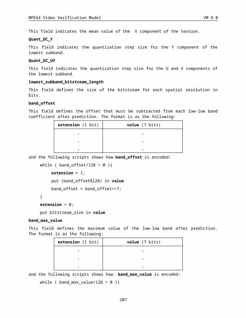
MPEG4 Video Verification Model VM 8.0
9 APPENDIX D: OFF-LINE SPRITE GENERATION
For a natural video object, sprite refers to a representative view collected from a video sequence, from which the video can be reconstructed. The effectiveness of this approach depends on whether the motion of the object (image motion) can be effectively represented by a global motion model, e.g., translation, zooming, affine and perspective. In the following, we give a summary of a tool to generate sprites from video sequences, which can be used as stand-alone module to generate off-line static sprite as well as on-line, dynamic sprite. Briefly, the process consists of processing each frame of the video sequence (for off-line generation, the frame rate can be different from the frame rate for coding) and registration of the frames based on the global motion information.
9.1 Perspective Motion EstimationLet’s assume that two images under consideration are I (x, y) and I’ (x’, y’). Using homogeneous coordinates, a 2D planar perspective transformation can be described as
wyx
mmmmmmmmm
wyx
876
543
210
'''
It can be also rewritten as
876
210,
mymxmmymxm
xii
iii
876
543,
mymxmmymxmy
ii
iii
The goal is to minimize the sum of the squared intensity errors over all corresponding pairs of pixels i inside both images I and I’. Two masks can be used to indicate the inside areas (wi is set to zero if both (x, y) and (x’, y’) are inside the masks, otherwise set to one).
i
iiiiii
ii ewyxIyxIwE 22,,,, )],(),('[
Since (x’, y’) generally do not fall on integer pixel coordinates, a bilinear interpolation of the intensities in I’ is used to perform the re-sampling (see Sec 1.1.3.1.4.).
The Levenberg-Marquardt iterative nonlinear minimization algorithm is employed to perform the minimization. This algorithm requires computation of the partial derivatives of ei with respect to the unknown motion parameters {m0, …, m7}. For example,
)''
''( ,,
7 yIy
xIx
Dy
me
iii
ii
''
0 xI
Dx
me
i
ii
where Di is the denominator. From these partial derivatives, the Levenberg-Marquardt algorithm computes an approximate Hessian matrix A and the weighted gradient vector b with components
207
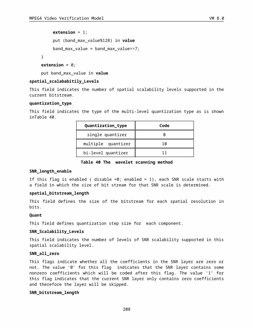
MPEG4 Video Verification Model VM 8.0
l
i
i k
ikl m
emea
k
i
iik m
eeb
and then updates the motion parameter estimate m by an amount Dm = A-1b. The complete perspective motion estimation algorithm consists of the following steps:
1. For each pixel i at location (xi, yi), compute its corresponding position in the position (x’ i, y’i); compute the error ei; compute the partial derivative of ei with respect to the mk; add the pixel’s contribution to A and b.
2. Solve the system of equations ADm = b and update the motion parameters m(t+1)= m(t) + Dm.
3. Repeat the above process for a fixed number of steps, e.g. 8.
For the convenience of other developers, we attach the complete C++ code in the end.
9.2 Sprite Generation Using the Perspective Motion Estimation
Let’s assume the image sequence includes n frames, Ii, i = 0, 1, …, n-1. The sprite Sk is generated using Ii, i = 0, …, k-1. The complete sprite generation algorithm includes the following steps:
1. S0 = I0 ; M0 = 0
2. For (i = 1; i < n; i++) {
Initiate Mi = Mi-1
Find perspective motion parameters Mi between Ii and Si-1;
Warp Ii towards Si-1 using Mi to get the warped image Wi (see 1.1.3.1.4.);
Blend Wi with Si-1 to obtain Si using Si = (i Si-1 + Wi) / (i + 1);
}
Note that the way we incrementally blend the new image to the previous sprite puts an equal weight to all the images contributing to the sprite. This could suppress the noise in individual images. We also attach the corresponding C++ code in the end.
The final sprite is Sn. In order to increase the speed, a Gaussian pyramid can be used. In that case, the perspective motion parameters from the previous level should be propagated to the next level according to the following rule:
m6 = m6/2 ; m7 = m7/2 ; m2 = m2 * 2 ; m5 = m5 * 2
The whole diagram of the sprite generation algorithm is shown below.
Some experimental results can be found from MPEG ftp site 'drop.chips.ibm.com:Chicago/Contrib/m1350.zip'.
208
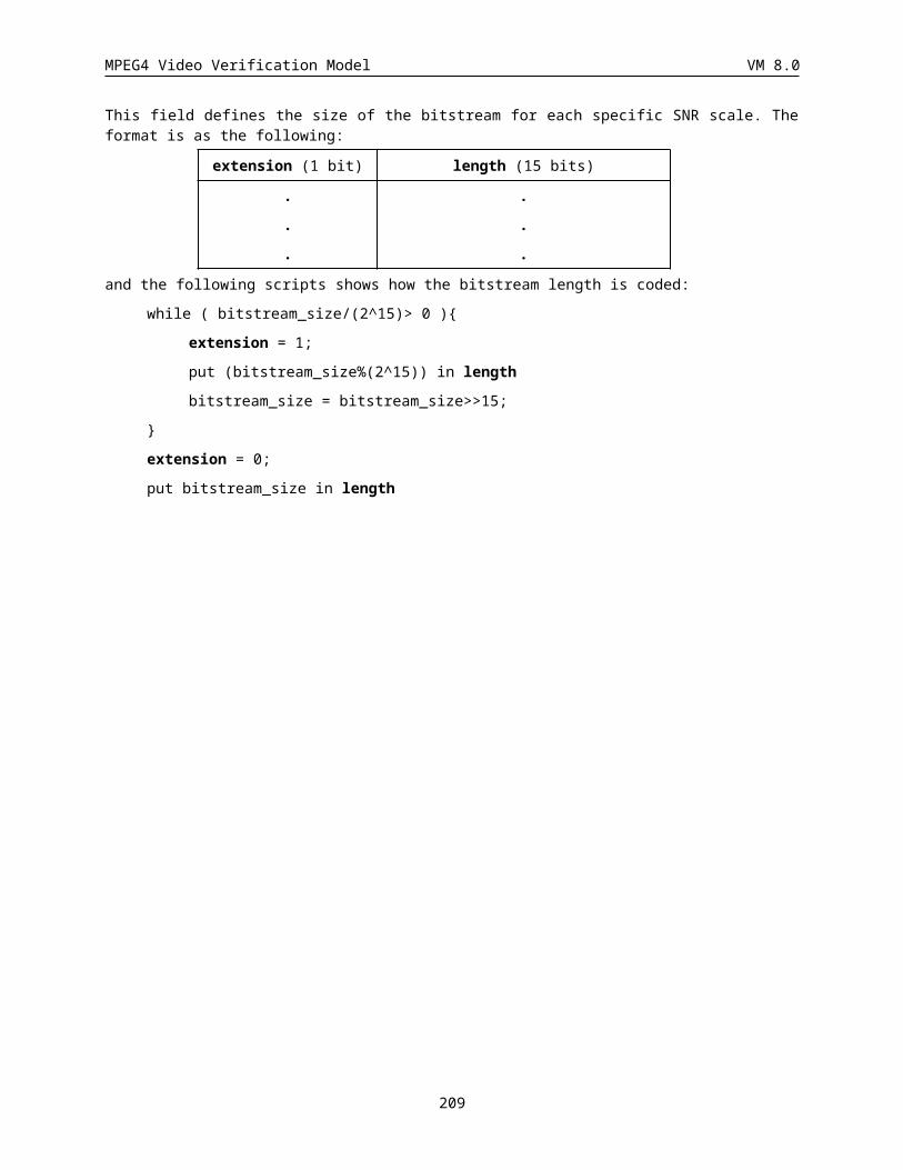
MPEG4 Video Verification Model VM 8.0
MotionEstimation Warping Blending
Frame Memory
VOP
Sprite
Mask
9.3 C++ Sample CodePerspective motion estimation
Void CSprite::motionPerspective(CFloatImage *pI, CFloatImage *pIA, const CRect &rctI, // Goal: minimize the error in pI. pI1 should be sprite.CFloatImage *pI1, CFloatImage *pI1A, const CRect &rctI1,CMatrix &M, Double &dE2) {
UInt i, j;Double dm[3][3], db[8], dA[8][8];for (j = 0; j < 8; j++)
for (i = 0; i < 8; i++)dA[j][i] = 0.;
for (i = 0; i < 8; i++)db[i]=0.;
dm[0][0] = M.GetCoeff(0,0);dm[0][1] = M.GetCoeff(0,1);dm[0][2] = M.GetCoeff(0,2);dm[1][0] = M.GetCoeff(1,0);dm[1][1] = M.GetCoeff(1,1);dm[1][2] = M.GetCoeff(1,2);dm[2][0] = M.GetCoeff(2,0);dm[2][1] = M.GetCoeff(2,1);dm[2][2] = M.GetCoeff(2,2);dE2 = 0.;Int stop = 0;for (CoordI y = rctI.top; y < rctI.bottom; y++) {
Double dy = (Double) y;for (CoordI x = rctI.left; x < rctI.right; x++)
if (pIA -> pixel (x, y) == 255.0) {CoordI x1, y1;Double dx1, dy1;Double dx = (Double) x;Double dt = dm[0][0] * dx + dm[0][1] * dy + dm[0][2];Double du = dm[1][0] * dx + dm[1][1] * dy + dm[1][2];Double dv = dm[2][0] * dx + dm[2][1] * dy + 1.;Double dtOv = dt / dv;Double duOv = du / dv;
209
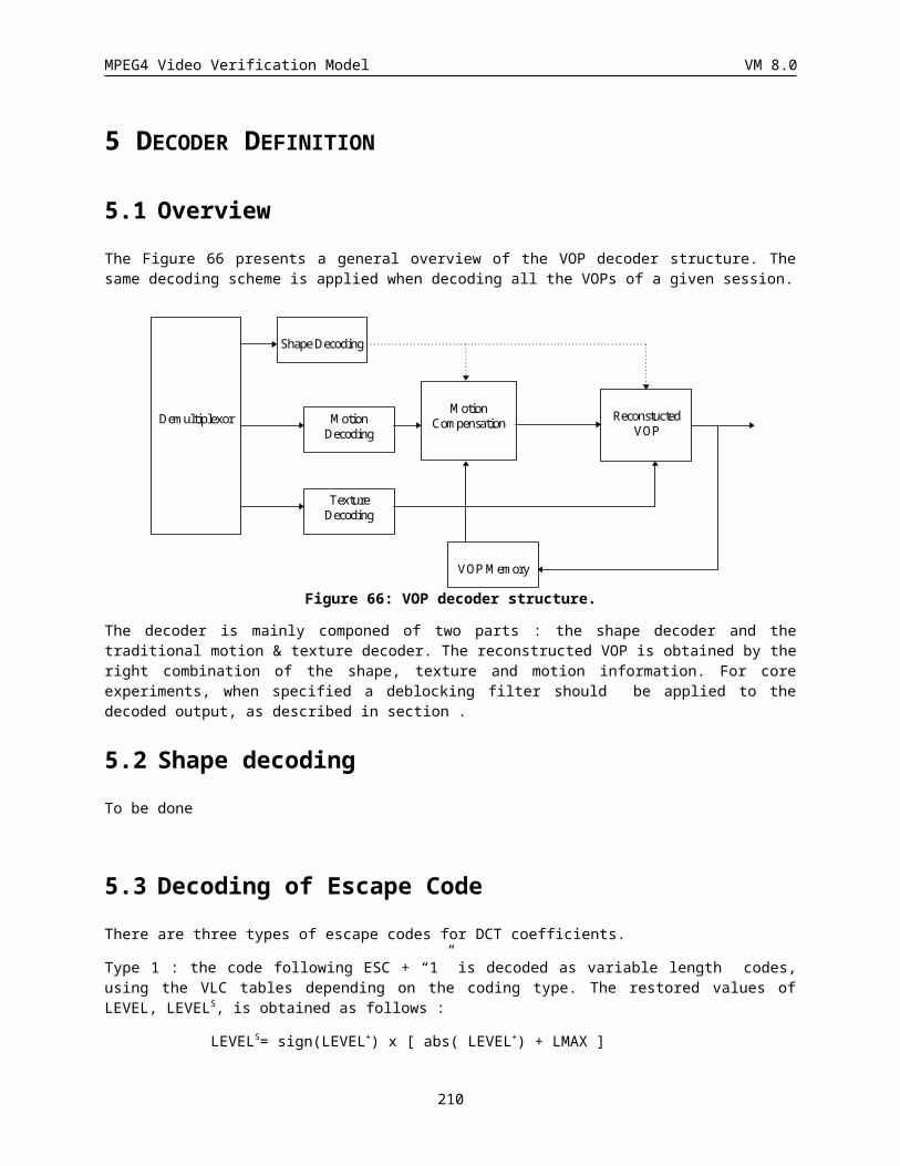
MPEG4 Video Verification Model VM 8.0
dx1 = dtOv;dy1 = duOv;x1 = (CoordI) (dx1);y1 = (CoordI) (dy1);if ((x1 >= rctI1.left) && ((x1+1) < rctI1.right)
&& (y1 >= rctI1.top) && ((y1+1) < rctI1.bottom) &&(pI1A -> pixel (x1, y1) == 255.0) &&(pI1A -> pixel (x1, y1+1) == 255.0)&&(pI1A -> pixel (x1+1, y1) == 255.0) &&(pI1A -> pixel ((CoordI)(x1+1), (CoordI)(y1+1)) == 255.0)){stop++;Double d1Ov = 1 / dv;Double dxOv = dx / dv;Double dyOv = dy / dv;Double dk, d1mk, dl, d1ml;dk = dx1 - x1;d1mk = 1. - dk;dl = dy1 - y1;d1ml = 1. - dl;Double I1x1y1[2][2];I1x1y1[0][0] = (Double) pI1-> pixel x1, y1);I1x1y1[1][0] = (Double) pI1-> pixel(x1 + 1, y1);I1x1y1[0][1] = (Double) pI1-> pixel(x1, y1 + 1);I1x1y1[1][1] = (Double) pI1-> pixel((CoordI)(x1 + 1),(CoordI)(y1+1));Double dI1=d1mk*d1ml*I1x1y1[0][0] + dk*d1ml*I1x1y1[1][0]
+ d1mk*dl*I1x1y1[0][1] + dk*dl*I1x1y1[1][1];Double de = dI1 - pI -> pixel (x, y);Double dI1dx = (I1x1y1[1][0]-I1x1y1[0][0])*d1ml
+(I1x1y1[1][1]-I1x1y1[0][1])*dl;Double dI1dy = (I1x1y1[0][1]-I1x1y1[0][0])*d1mk
+(I1x1y1[1][1]-I1x1y1[1][0])*dk;Double ddedm[8];ddedm[0] = dxOv*dI1dx;ddedm[1] = dyOv*dI1dx;ddedm[2] = d1Ov*dI1dx;ddedm[3] = dxOv*dI1dy;ddedm[4] = dyOv*dI1dy;ddedm[5] = d1Ov*dI1dy;ddedm[6] = -dtOv*dxOv*dI1dx-duOv*dxOv*dI1dy;ddedm[7] = -dtOv*dyOv*dI1dx-duOv*dyOv*dI1dy;db[0] += -de*ddedm[0]; db[1] += -de*ddedm[1];db[2] += -de*ddedm[2];db[3] += -de*ddedm[3];db[4] += -de*ddedm[4];db[5] += -de*ddedm[5];db[6] += -de*ddedm[6];db[7] += -de*ddedm[7];for(j = 0; j < 8; j++)
for (i = 0; i <= j; i++)dA[j][i] += ddedm[j] * ddedm[i];
dE2 += de*de; }
}}if (stop > -1) {
for (j = 0; j < 8; j++)for (i = j + 1; i < 8; i++)
dA[j][i] = dA[i][j];
210
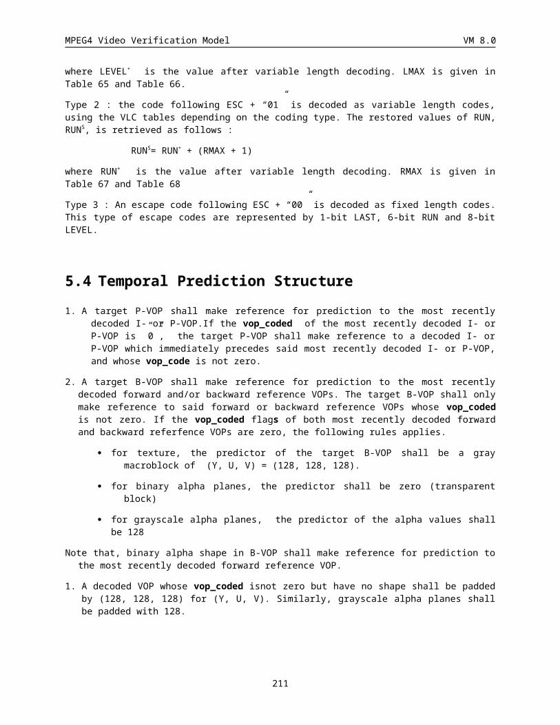
MPEG4 Video Verification Model VM 8.0
Double dL = 0.0;CMatrix A(8, 8, &dA[0][0]);CMatrix b(8, 1, &db[0]);CMatrix Dm(8, 1);CMatrix DM(3, 3);Dm = (A + dL * I(8)).Inv() * b;DM.SetCoeff(0,0,Dm.GetCoeff(0,0));DM.SetCoeff(0,1,Dm.GetCoeff(1,0));DM.SetCoeff(0,2,Dm.GetCoeff(2,0));DM.SetCoeff(1,0,Dm.GetCoeff(3,0));DM.SetCoeff(1,1,Dm.GetCoeff(4,0));DM.SetCoeff(1,2,Dm.GetCoeff(5,0));DM.SetCoeff(2,0,Dm.GetCoeff(6,0));DM.SetCoeff(2,1,Dm.GetCoeff(7,0));M += DM;
}else
dE2 = 1.0e+30;}
Blending
Void CSprite::blending(CFloatImage* pSpriteY, CFloatImage* pSpriteU, CFloatImage* pSpriteV, CFloatImage* pSpriteA, CFloatImage* pSpriteWeight, CFloatImage* WarpedY, CFloatImage* WarpedU, CFloatImage* WarpedV, CFloatImage* WarpedA) {
Long disp = pSpriteY -> where ().width() - WarpedY -> where ().width();CoordI leftWarped = WarpedY -> where ().left;CoordI rightWarped = WarpedY -> where ().right;CoordI topWarped = WarpedY -> where ().top;CoordI bottomWarped = WarpedY -> where ().bottom;PixelF* ppWarpedY = (PixelF*) WarpedY -> pixels ();PixelF* ppWarpedU = (PixelF*) WarpedU -> pixels ();PixelF* ppWarpedV = (PixelF*) WarpedV -> pixels ();PixelF* ppWarpedA = (PixelF*) WarpedA -> pixels ();PixelF* ppSpriteY = (PixelF*) pSpriteY -> pixels (leftWarped, topWarped);PixelF* ppSpriteU = (PixelF*) pSpriteU -> pixels (leftWarped, topWarped);PixelF* ppSpriteV = (PixelF*) pSpriteV -> pixels (leftWarped, topWarped); PixelF* ppSpriteA = (PixelF*) pSpriteA -> pixels (leftWarped, topWarped);PixelF* ppSpriteW = (PixelF*) pSpriteWeight -> pixels (leftWarped, topWarped);
for (CoordI y = topWarped; y < bottomWarped; y++) {for (CoordI x = leftWarped; x < rightWarped; x++) {
Float sumY = (*ppSpriteY) * (*ppSpriteW) + (*ppWarpedY) * (*ppWarpedA);Float sumU = (*ppSpriteU) * (*ppSpriteW) + (*ppWarpedU) * (*ppWarpedA);
Float sumV = (*ppSpriteV) * (*ppSpriteW) + (*ppWarpedV) * (*ppWarpedA);
if (*ppWarpedA == 255.0) {*ppSpriteW = *ppSpriteW + *ppWarpedA;*ppSpriteY = sumY / (*ppSpriteW);*ppSpriteU = sumU / (*ppSpriteW);*ppSpriteV = sumV / (*ppSpriteW);*ppSpriteA = 255.0f;
}ppSpriteY++; ppSpriteU++; ppSpriteV++; ppSpriteA++; ppSpriteW++;ppWarpedY++; ppWarpedU++; ppWarpedV++; ppWarpedA++;
}ppSpriteY += disp; ppSpriteU += disp; ppSpriteV += disp; ppSpriteA += disp;ppSpriteW += disp;
}}
211
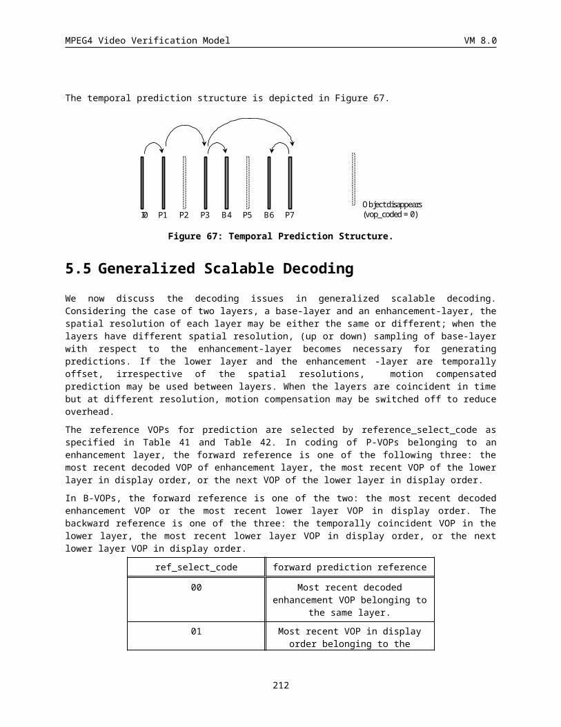
MPEG4 Video Verification Model VM 8.0
10APPENDIX E: C-SOURCE CODE FOR FEATHERING FILTER#define OPAQUE_LEVEL 255 /*255 or VOP_constant_alpha_value*/#define TRUE 1#define FALSE 0#define BIN_TH 1 /*threshold for 0->0, [1,255]-> OPAQUE_LEVEL*/ #define MAX_ITERATION 7 /* video_object_layer_feather_dist*/#define TAPERING_LIMIT 90 /* 0-100(%) */
/* image structure*/typedef unsigned char PIXEL;struct image{
PIXEL * mat;int width;int height;
};typedef struct image IMAGE;/* encoder*/void feathering_analysys( IMAGE *in, IMAGE *out );
/*encoder*/void void feathering_iteration(IMAGE *in, int n_iteration, PIXEL table[MAX_ITERATION][15], IMAGE *out );
/* decision filter coefficient */void make_table( IMAGE *grey, IMAGE *bin, PIXEL *table );
/* decision of cascade filtering*/int is_filter_cascaded( PIXEL * table );
/* feathering filter */void feathering( IMAGE *in_out, PIXEL *table );
void gray2binary( IMAGE *grey, IMAGE *bin, PIXEL threshold);void print_table( PIXEL *table );void get_work_image( IMAGE *in, IMAGE *work );
/***********************ENCODER********************/void feathering_analysis( IMAGE *in, IMAGE *out){
int itertaion = 0;int end_itertaion = FALSE;PIXEL table[MAX_ITERTAION][15];gray2binary( in, out, BIN_TH );while(itertaion<MAX_ITERTAION && end_itertaion==FALSE){
make_table( in, out, table[itertaion] );/*OUTPUT of ENCODER, i.e., filter description*/print_table( table[itertaion] );end_itertaion = (is_filter_cascaded(table[itertaion]) == TRUE)? FALSE : TRUE;/* local decode */if(end_itertaion==FALSE) feathering( out, table[itertaion] );
itertaion++;}
}/***********************DECODER********************/void feathering_iteration(IMAGE *in, int n_iteration,
PIXEL table[MAX_ITERATION][15], IMAGE *out ){
212
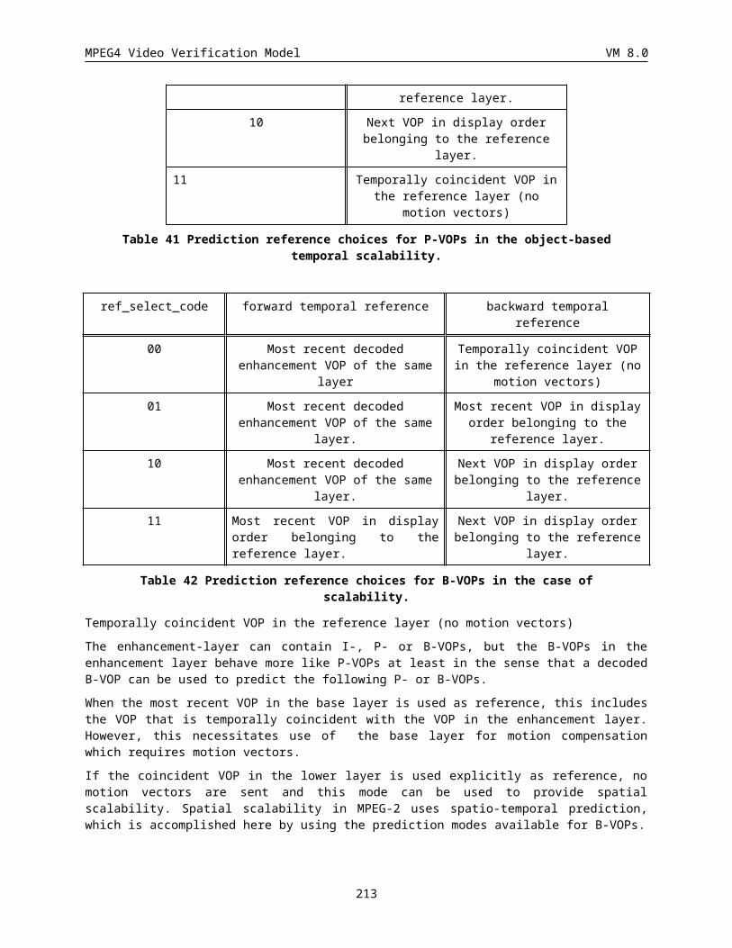
MPEG4 Video Verification Model VM 8.0
int itertaion = 0;gray2binary( in, out, BIN_TH );while(iteration =0; itertaion<n_iteration; iteration++)
feathering( out, table[itertaion] );}
void feathering( IMAGE *in_out, PIXEL *table ){int i, j;int pix, label;int w = in_out->width;int h = in_out->height;int w2 = w + 2;int h2 = h + 2;IMAGE *work;PIXEL *work_mat;PIXEL *in_out_mat = in_out->mat;work = new_image( w2, h2 );get_work_image( in_out, work );work_mat = work->mat;work_mat += w2;for( i=0; i<h; i++){
work_mat++;for( j=0; j<w; j++){
if( *work_mat == OPAQUE_LEVEL ){pix = (*(work_mat-w2)==OPAQUE_LEVEL )? 1 : 0 ;label = pix << 1;pix = (*(work_mat-1)==OPAQUE_LEVEL )? 1 : 0 ;label = (pix | label) << 1;pix = (*(work_mat+1)==OPAQUE_LEVEL )? 1 : 0 ;label = (pix | label) << 1;pix = (*(work_mat+w2)==OPAQUE_LEVEL )? 1 : 0 ;label = pix | label;if(label<15){ /* 15 -> 1111 */
*in_out_mat = table[label];}
}work_mat++; in_out_mat++;
}work_mat++;
}delete_image( work );
}
void gray2binary( IMAGE *grey, IMAGE *bin, PIXEL threshold){int i;int size = grey->width * grey->height;PIXEL *grey_mat = grey->mat;PIXEL *bin_mat = bin->mat;for(i=0; i<size; i++){
*bin_mat = (*grey_mat<threshold)? 0 : OPAQUE_LEVEL ;grey_mat++; bin_mat++;
}}
void make_table( IMAGE *grey, IMAGE *bin, PIXEL *table ){int pix, label;int sum[15] = {};int num[15] = {};int i, j;
213
MPEG4 Video Verification Model VM 8.0
int w = grey->width;int h = grey->height;int w2 = w + 2;int h2 = h + 2;IMAGE *work_bin;PIXEL *work_bin_mat;PIXEL *grey_mat = grey->mat;
work_bin = new_image(w2, h2);get_work_image( bin, work_bin );work_bin_mat = work_bin->mat;work_bin_mat += w2;for(i=0; i<h; i++){work_bin_mat++;for(j=0; j<w; j++){
if( *work_bin_mat == OPAQUE_LEVEL ){pix = (*(work_bin_mat-w2)==OPAQUE_LEVEL )? 1 : 0 ;label = pix << 1;pix = (*(work_bin_mat-1)==OPAQUE_LEVEL )? 1 : 0 ;label = (pix | label) << 1;pix = (*(work_bin_mat+1)==OPAQUE_LEVEL )? 1 : 0 ;label = (pix | label) << 1;pix = (*(work_bin_mat+w2)==OPAQUE_LEVEL )? 1 : 0 ;label = pix | label;if(label<15){ /* 15 -> 1111 */
sum[label] += *grey_mat;num[label] ++;
}} work_bin_mat++; grey_mat++;
}work_bin_mat++;}for(i=0; i<15; i++) table[i] = (num[i]>0)? (PIXEL)(sum[i]/num[i]) : OPAQUE_ELVEL;delete_image(work_bin);
}
void print_table( PIXEL * table ){int i;for(i=0; i<15; i++)
fprintf(stdout,"table[%2X] = %d\n", i, table[i]);fprintf(stdout,"\n");
}
int is_filter_cascaded( PIXEL *table ){int i;PIXEL valid_value;valid_value = OPAQUE_LEVEL * TAPERING_LIMIT / 100;
for( i=0; i<15; i++)if(table[i]<valid_value )
return( TRUE );return( FALSE );
}
void get_work_image( IMAGE *in, IMAGE *work ){int i, j;int w = in->width;int h = in->height;
214
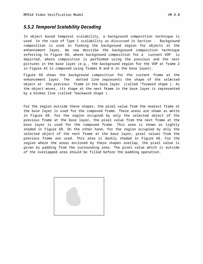
MPEG4 Video Verification Model VM 8.0
int w2 = work->width;int h2 = work->height;PIXEL *in_mat, *work_mat;in_mat = in->mat; work_mat = work->mat;for(i=0; i<h2; i++){
for(j=0; j<w2; j++){if(i>0 && i<h+1 && j>0 && j<w+1){
*work_mat = *in_mat;work_mat++; in_mat++;
}else{
*work_mat = 0;work_mat++;
}}
} work_mat = work->mat;for(i=0; i<h2; i++){
for(j=0; j<w2; j++){ if(i<1) *work_mat = *(work_mat+w2);else if(i>h) *work_mat = *(work_mat-w2);else if(j<1) *work_mat = *(work_mat+1);else if(j>w) *work_mat = *(work_mat-1);work_mat++;
}}
}
215
MPEG4 Video Verification Model VM 8.0
11APPENDIX F: PROBABILITY TABLES FOR SHAPE CODING(CAE)
These tables contain the probabilities for a binary alpha pixel being equal to 0 for intra and inter shape coding using CAE. All probabilities are normalised to the range [1,65535].
As an example, given an INTRA context number C, the probability that the pixel is zero is given by intra_prob[C].
USInt intra_prob[1024] = {
65267,16468,65003,17912,64573,8556,64252,5653,
40174,3932,29789,277,45152,1140,32768,2043,
4499,80,6554,1144,21065,465,32768,799,
5482,183,7282,264,5336,99,6554,563,
54784,30201,58254,9879,54613,3069,32768,58495,
32768,32768,32768,2849,58982,54613,32768,12892,
31006,1332,49152,3287,60075,350,32768,712,
39322,760,32768,354,52659,432,61854,150,
64999,28362,65323,42521,63572,32768,63677,18319,
4910,32768,64238,434,53248,32768,61865,13590,
16384,32768,13107,333,32768,32768,32768,32768,
32768,32768,1074,780,25058,5461,6697,233,
62949,30247,63702,24638,59578,32768,32768,42257,
32768,32768,49152,546,62557,32768,54613,19258,
62405,32569,64600,865,60495,10923,32768,898,
34193,24576,64111,341,47492,5231,55474,591,
65114,60075,64080,5334,65448,61882,64543,13209,
54906,16384,35289,4933,48645,9614,55351,7318,
49807,54613,32768,32768,50972,32768,32768,32768,
15159,1928,2048,171,3093,8,6096,74,
32768,60855,32768,32768,32768,32768,32768,32768,
32768,32768,32768,32768,32768,55454,32768,57672,
32768,16384,32768,21845,32768,32768,32768,32768,
32768,32768,32768,5041,28440,91,32768,45,
65124,10923,64874,5041,65429,57344,63435,48060,
61440,32768,63488,24887,59688,3277,63918,14021,
32768,32768,32768,32768,32768,32768,32768,32768,
690,32768,32768,1456,32768,32768,8192,728,
32768,32768,58982,17944,65237,54613,32768,2242,
32768,32768,32768,42130,49152,57344,58254,16740,
216
MPEG4 Video Verification Model VM 8.0
32768,10923,54613,182,32768,32768,32768,7282,
49152,32768,32768,5041,63295,1394,55188,77,
63672,6554,54613,49152,64558,32768,32768,5461,
64142,32768,32768,32768,62415,32768,32768,16384,
1481,438,19661,840,33654,3121,64425,6554,
4178,2048,32768,2260,5226,1680,32768,565,
60075,32768,32768,32768,32768,32768,32768,32768,
32768,32768,32768,32768,32768,32768,32768,32768,
16384,261,32768,412,16384,636,32768,4369,
23406,4328,32768,524,15604,560,32768,676,
49152,32768,49152,32768,32768,32768,64572,32768,
32768,32768,54613,32768,32768,32768,32768,32768,
4681,32768,5617,851,32768,32768,59578,32768,
32768,32768,3121,3121,49152,32768,6554,10923,
32768,32768,54613,14043,32768,32768,32768,3449,
32768,32768,32768,32768,32768,32768,32768,32768,
57344,32768,57344,3449,32768,32768,32768,3855,
58982,10923,32768,239,62259,32768,49152,85,
58778,23831,62888,20922,64311,8192,60075,575,
59714,32768,57344,40960,62107,4096,61943,3921,
39862,15338,32768,1524,45123,5958,32768,58982,
6669,930,1170,1043,7385,44,8813,5011,
59578,29789,54613,32768,32768,32768,32768,32768,
32768,32768,32768,32768,58254,56174,32768,32768,
64080,25891,49152,22528,32768,2731,32768,10923,
10923,3283,32768,1748,17827,77,32768,108,
62805,32768,62013,42612,32768,32768,61681,16384,
58982,60075,62313,58982,65279,58982,62694,62174,
32768,32768,10923,950,32768,32768,32768,32768,
5958,32768,38551,1092,11012,39322,13705,2072,
54613,32768,32768,11398,32768,32768,32768,145,
32768,32768,32768,29789,60855,32768,61681,54792,
32768,32768,32768,17348,32768,32768,32768,8192,
57344,16384,32768,3582,52581,580,24030,303,
62673,37266,65374,6197,62017,32768,49152,299,
54613,32768,32768,32768,35234,119,32768,3855,
31949,32768,32768,49152,16384,32768,32768,32768,
24576,32768,49152,32768,17476,32768,32768,57445,
51200,50864,54613,27949,60075,20480,32768,57344,
217
MPEG4 Video Verification Model VM 8.0
32768,32768,32768,32768,32768,45875,32768,32768,
11498,3244,24576,482,16384,1150,32768,16384,
7992,215,32768,1150,23593,927,32768,993,
65353,32768,65465,46741,41870,32768,64596,59578,
62087,32768,12619,23406,11833,32768,47720,17476,
32768,32768,2621,6554,32768,32768,32768,32768,
32768,32768,5041,32768,16384,32768,4096,2731,
63212,43526,65442,47124,65410,35747,60304,55858,
60855,58982,60075,19859,35747,63015,64470,25432,
58689,1118,64717,1339,24576,32768,32768,1257,
53297,1928,32768,33,52067,3511,62861,453,
64613,32768,32768,32768,64558,32768,32768,2731,
49152,32768,32768,32768,61534,32768,32768,35747,
32768,32768,32768,32768,13107,32768,32768,32768,
32768,32768,32768,32768,20480,32768,32768,32768,
32768,32768,32768,54613,40960,5041,32768,32768,
32768,32768,32768,3277,64263,57592,32768,3121,
32768,32768,32768,32768,32768,10923,32768,32768,
32768,8192,32768,32768,5461,6899,32768,1725,
63351,3855,63608,29127,62415,7282,64626,60855,
32768,32768,60075,5958,44961,32768,61866,53718,
32768,32768,32768,32768,32768,32768,6554,32768,
32768,32768,32768,32768,2521,978,32768,1489,
58254,32768,58982,61745,21845,32768,54613,58655,
60075,32768,49152,16274,50412,64344,61643,43987,
32768,32768,32768,1638,32768,32768,32768,24966,
54613,32768,32768,2427,46951,32768,17970,654,
65385,27307,60075,26472,64479,32768,32768,4681,
61895,32768,32768,16384,58254,32768,32768,6554,
37630,3277,54613,6554,4965,5958,4681,32768,
42765,16384,32768,21845,22827,16384,32768,6554,
65297,64769,60855,12743,63195,16384,32768,37942,
32768,32768,32768,32768,60075,32768,62087,54613,
41764,2161,21845,1836,17284,5424,10923,1680,
11019,555,32768,431,39819,907,32768,171,
65480,32768,64435,33803,2595,32768,57041,32768,
61167,32768,32768,32768,32768,32768,32768,1796,
60855,32768,17246,978,32768,32768,8192,32768,
32768,32768,14043,2849,32768,2979,6554,6554,
218
MPEG4 Video Verification Model VM 8.0
65507,62415,65384,61891,65273,58982,65461,55097,
32768,32768,32768,55606,32768,2979,3745,16913,
61885,13827,60893,12196,60855,53248,51493,11243,
56656,783,55563,143,63432,7106,52429,445,
65485,1031,65020,1380,65180,57344,65162,36536,
61154,6554,26569,2341,63593,3449,65102,533,
47827,2913,57344,3449,35688,1337,32768,22938,
25012,910,7944,1008,29319,607,64466,4202,
64549,57301,49152,20025,63351,61167,32768,45542,
58982,14564,32768,9362,61895,44840,32768,26385,
59664,17135,60855,13291,40050,12252,32768,7816,
25798,1850,60495,2662,18707,122,52538,231,
65332,32768,65210,21693,65113,6554,65141,39667,
62259,32768,22258,1337,63636,32768,64255,52429,
60362,32768,6780,819,16384,32768,16384,4681,
49152,32768,8985,2521,24410,683,21535,16585,
65416,46091,65292,58328,64626,32768,65016,39897,
62687,47332,62805,28948,64284,53620,52870,49567,
65032,31174,63022,28312,64299,46811,48009,31453,
61207,7077,50299,1514,60047,2634,46488,235
};
USInt inter_prob[512] = {
65532,62970,65148,54613,62470,8192,62577,8937,
65480,64335,65195,53248,65322,62518,62891,38312,
65075,53405,63980,58982,32768,32768,54613,32768,
65238,60009,60075,32768,59294,19661,61203,13107,
63000,9830,62566,58982,11565,32768,25215,3277,
53620,50972,63109,43691,54613,32768,39671,17129,
59788,6068,43336,27913,6554,32768,12178,1771,
56174,49152,60075,43691,58254,16384,49152,9930,
23130,7282,40960,32768,10923,32768,32768,32768,
27307,32768,32768,32768,32768,32768,32768,32768,
36285,12511,10923,32768,45875,16384,32768,32768,
16384,23831,4369,32768,8192,10923,32768,32768,
10175,2979,18978,10923,54613,32768,6242,6554,
1820,10923,32768,32768,32768,32768,32768,5461,
28459,593,11886,2030,3121,4681,1292,112,
42130,23831,49152,29127,32768,6554,5461,2048,
219
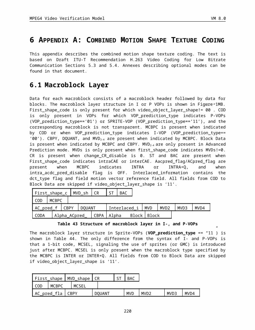
MPEG4 Video Verification Model VM 8.0
65331,64600,63811,63314,42130,19661,49152,32768,
65417,64609,62415,64617,64276,44256,61068,36713,
64887,57525,53620,61375,32768,8192,57344,6554,
63608,49809,49152,62623,32768,15851,58982,34162,
55454,51739,64406,64047,32768,32768,7282,32768,
49152,58756,62805,64990,32768,14895,16384,19418,
57929,24966,58689,31832,32768,16384,10923,6554,
54613,42882,57344,64238,58982,10082,20165,20339,
62687,15061,32768,10923,32768,10923,32768,16384,
59578,34427,32768,16384,32768,7825,32768,7282,
58052,23400,32768,5041,32768,2849,32768,32768,
47663,15073,57344,4096,32768,1176,32768,1320,
24858,410,24576,923,32768,16384,16384,5461,
16384,1365,32768,5461,32768,5699,8192,13107,
46884,2361,23559,424,19661,712,655,182,
58637,2094,49152,9362,8192,85,32768,1228,
65486,49152,65186,49152,61320,32768,57088,25206,
65352,63047,62623,49152,64641,62165,58986,18304,
64171,16384,60855,54613,42130,32768,61335,32768,
58254,58982,49152,32768,60985,35289,64520,31554,
51067,32768,64074,32768,40330,32768,34526,4096,
60855,32768,63109,58254,57672,16384,31009,2567,
23406,32768,44620,10923,32768,32768,32099,10923,
49152,49152,54613,60075,63422,54613,46388,39719,
58982,32768,54613,32768,14247,32768,22938,5041,
32768,49152,32768,32768,25321,6144,29127,10999,
41263,32768,46811,32768,267,4096,426,16384,
32768,19275,49152,32768,1008,1437,5767,11275,
5595,5461,37493,6554,4681,32768,6147,1560,
38229,10923,32768,40960,35747,2521,5999,312,
17052,2521,18808,3641,213,2427,574,32,
51493,42130,42130,53053,11155,312,2069,106,
64406,45197,58982,32768,32768,16384,40960,36864,
65336,64244,60075,61681,65269,50748,60340,20515,
58982,23406,57344,32768,6554,16384,19661,61564,
60855,47480,32768,54613,46811,21701,54909,37826,
32768,58982,60855,60855,32768,32768,39322,49152,
57344,45875,60855,55706,32768,24576,62313,25038,
54613,8192,49152,10923,32768,32768,32768,32768,
220
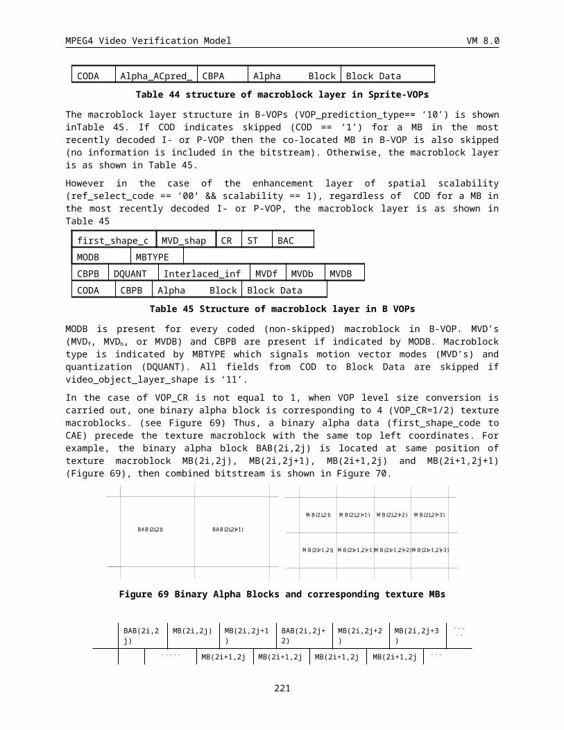
MPEG4 Video Verification Model VM 8.0
32768,19661,16384,51493,32768,14043,40050,44651,
59578,5174,32768,6554,32768,5461,23593,5461,
63608,51825,32768,23831,58887,24032,57170,3298,
39322,12971,16384,49152,1872,618,13107,2114,
58982,25705,32768,60075,28913,949,18312,1815,
48188,114,51493,1542,5461,3855,11360,1163,
58982,7215,54613,21487,49152,4590,48430,1421,
28944,1319,6868,324,1456,232,820,7,
61681,1864,60855,9922,4369,315,6589,14
};
221
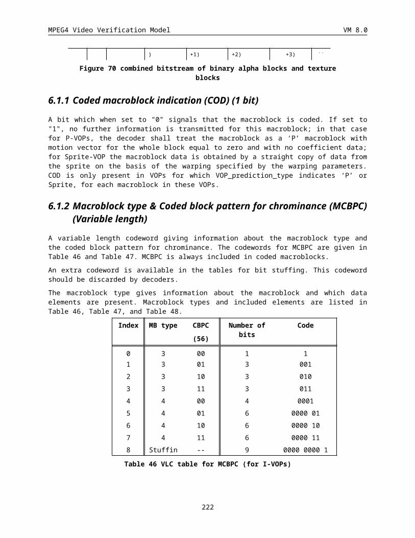
MPEG4 Video Verification Model VM 8.0
12APPENDIX G: ARITHMETIC ENCODING/DECODING CODES FOR SHAPE CODING
12.1 Structures and Typedefstypedef void Void;typedef int Int;typedef unsigned short int USInt;#define CODE_BIT 32#define HALF ((unsigned) 1 << (CODE_BITS-1))#define QUARTER (1 << (CODE_BITS-2))struct arcodec {
UInt L; /* lower bound */UInt R; /* code range */UInt V; /* current code value */UInt arpipe;Int bits_to_follow; /* follow bit count */Int first_bit;Int nzeros;Int nonzero;Int nzerosf;Int extrabits;
};typedef struct arcodec ArCoder;typedef struct arcodec ArDecoder;#define MAXHEADING 8#define MAXMIDDLE 16#define MAXTRAILING 8
12.2 Encoder Source/* START ENCODING A STREAM OF SYMBOLS */Void StartArCoder(ArCoder *coder) {
coder->L = 0;coder->R = HALF-1;coder->bits_to_follow = 0;coder->first_bit = 1;coder->nzeros = MAXHEADING;coder->nonzero = 0;
}/* FINISH ENCODING THE STREAM */Int StopArCoder(ArCoder *coder, Bitstream *bitstream) {
Int a = (coder->L) >> (CODE_BITS-3);Int b = (coder->R + coder->L) >> (CODE_BITS-3);Int nbits, bits, i;if (b == 0)
b = 8;if (b-a >= 4 || (b-a == 3 && a&1)) {
nbits = 2;bits = (a>>1) + 1;
}else {
nbits = 3;
222
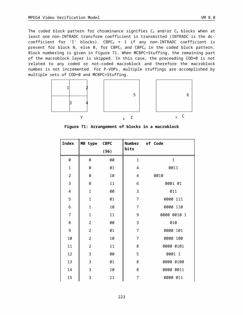
MPEG4 Video Verification Model VM 8.0
bits = a + 1;}for (i = 1; i <= nbits; i++)
BitPlusFollow(((bits >> (nbits-i)) & 1), coder, bitstream);if (coder->nzeros < MAXMIDDLE-MAXTRAILING || coder->nonzero == 0) {
BitPlusFollow(1, coder, bitstream);}return;
}Void BitByItself(Int bit, ArCoder *coder, Bitstream* bitstream) {
BitstreamPutBit(bitstream,bit); /* Output the bit */if (bit == 0) {
coder->nzeros--;if (coder->nzeros == 0) {
BitstreamPutBit(bitstream,1);coder->nonzero = 1;coder->nzeros = MAXMIDDLE;
}}else {
coder->nonzero = 1;coder->nzeros = MAXMIDDLE;
}}/* OUTPUT BITS PLUS FOLLOWING OPPOSITE BITS */Void BitPlusFollow(Int bit, ArCoder *coder, Bitstream *bitstream) {
if (!coder->first_bit)BitByItself(bit, coder, bitstream);
elsecoder->first_bit = 0;
while ((coder->bits_to_follow) > 0) {BitByItself(!bit, coder, bitstream);coder->bits_to_follow -= 1;
}}/* ENCODE A BINARY SYMBOL */Void ArCodeSymbol(Int bit, USInt c0, ArCoder *coder, Bitstream *bitstream) {
Int bits = 0;USInt c1 = (1<<16) - c0;Int LPS = (c0 > c1);USInt cLPS = (LPS) ? c1 : c0;unsigned long rLPS;rLPS = ((coder->R) >> 16) * cLPS;if (bit == LPS) {
coder->L += coder->R - rLPS;coder->R = rLPS;
}else
coder->R -= rLPS;ENCODE_RENORMALISE(coder,bitstream);
}Void ENCODE_RENORMALISE(ArCoder *coder, Bitstream *bitstream) {
while (coder->R < QUARTER) { if (coder->L >= HALF) {
BitPlusFollow(1,coder,bitstream); coder->L -= HALF;
} else
if (coder->L+coder->R <= HALF)
223
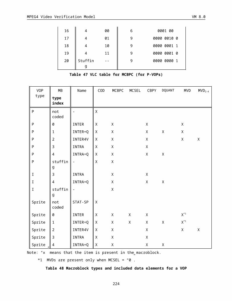
MPEG4 Video Verification Model VM 8.0
BitPlusFollow(0,coder,bitstream);else {
coder->bits_to_follow++; coder->L -= QUARTER;
} coder->L += coder->L; coder->R += coder->R;
}}
12.3 Decoder SourceVoid StartArDecoder(ArDecoder *decoder, Bitstream *bitstream) {
Int i,j;decoder->V = 0;decoder->nzerosf = MAXHEADING;decoder->extrabits = 0;for (i = 1; i<CODE_BITS; i++) {
j=BitstreamLookBit(bitstream,i+decoder->extrabits);decoder->V += decoder->V + j;if (j == 0) {
decoder->nzerosf--;if (decoder->nzerosf == 0) {
decoder->extrabits++;decoder->nzerosf = MAXMIDDLE;
}}else
decoder->nzerosf = MAXMIDDLE;}decoder->L = 0;decoder->R = HALF - 1;decoder->bits_to_follow = 0;decoder->arpipe = decoder->V;decoder->nzeros = MAXHEADING;decoder->nonzero = 0;
}Void StopArDecoder(ArDecoder *decoder, Bitstream *bitstream) {
Int a = decoder->L >> (CODE_BITS-3);Int b = (decoder->R + decoder->L) >> (CODE_BITS-3);Int nbits,i;if (b == 0)
b = 8;if (b-a >= 4 || (b-a == 3 && a&1))
nbits = 2;else
nbits = 3;for (i = 1; i <= nbits-1; i++)
AddNextInputBit(bitstream, decoder);if (decoder->nzeros < MAXMIDDLE-MAXTRAILING || decoder->nonzero == 0)
BitstreamFlushBits(bitstream,1);}Void AddNextInputBit(Bitstream *bitstream, ArDecoder *decoder) {
Int i;if (((decoder->arpipe >> (CODE_BITS-2))&1) == 0) {
decoder->nzeros--;if (decoder->nzeros == 0) {
BitstreamFlushBits(bitstream,1);
224
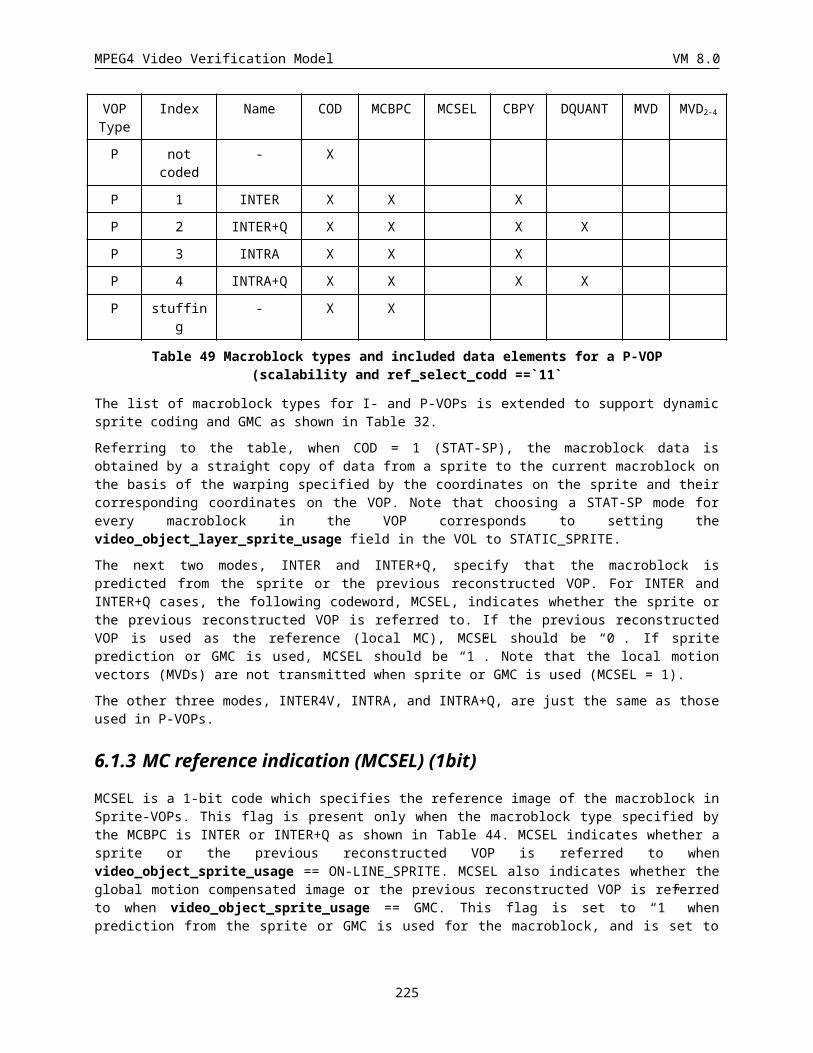
MPEG4 Video Verification Model VM 8.0
decoder->extrabits--;decoder->nzeros = MAXMIDDLE;decoder->nonzero = 1;
}}else {
decoder->nzeros = MAXMIDDLE;decoder->nonzero = 1;
}BitstreamFlushBits(bitstream,1);i = (Int)BitstreamLookBit(bitstream, CODE_BITS-1+decoder->extrabits);decoder->V += decoder->V + i;decoder->arpipe += decoder->arpipe + i;if (i == 0) {
decoder->nzerosf--;if (decoder->nzerosf == 0) {
decoder->nzerosf = MAXMIDDLE;decoder->extrabits++;
}}else
decoder->nzerosf = MAXMIDDLE;}Int ArDecodeSymbol(USInt c0, ArDecoder *decoder, Bitstream *bitstream ) {
Int bit;Int c1 = (1<<16) - c0;Int LPS = c0 > c1;Int cLPS = LPS ? c1 : c0;unsigned long rLPS;rLPS = ((decoder->R) >> 16) * cLPS;if ((decoder->V - decoder->L) >= (decoder->R - rLPS)) {
bit = LPS;decoder->L += decoder->R - rLPS;decoder->R = rLPS;
}else {
bit = (1-LPS);decoder->R -= rLPS;
}DECODE_RENORMALISE(decoder,bitstream);return(bit);
}Void DECODE_RENORMALISE(ArDecoder *decoder, Bitstream *bitstream) {
while (decoder->R < QUARTER) {if (decoder->L >= HALF) {
decoder->V -= HALF;decoder->L -= HALF;decoder->bits_to_follow = 0;
}else
if (decoder->L + decoder->R <= HALF) decoder->bits_to_follow = 0;
else{decoder->V -= QUARTER;decoder->L -= QUARTER;(decoder->bits_to_follow)++;
}decoder->L += decoder->L;decoder->R += decoder->R;
225
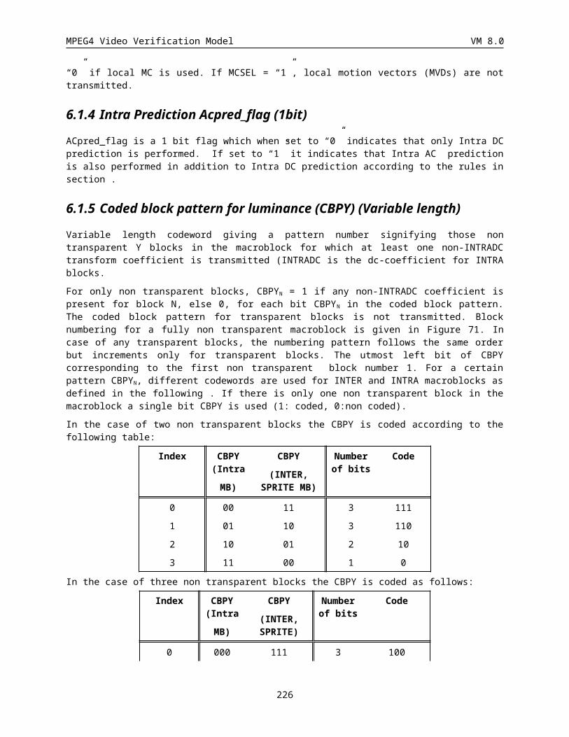
MPEG4 Video Verification Model VM 8.0
AddNextInputBit(bitstream, decoder);}
}
· BitstreamPutBit(bitstream,bit): Writes a single bit to the bitstream.
· BitstreamLookBit(bitstream,nbits) : Looks nbits ahead in the bitstream beginning from the current position in the bitstream and returns the bit.
· BitstreamFlushBits(bitstream,nbits) : Moves the current bitstream position forward by nbits.
· The parameter c0 (used in ArCodeSymbol() and ArDecodeSymbol()) is taken directly from the probability tables of Appendix H. That is, for the pixel to be coded/decoded, c0 is the probability than this pixel is equal to zero. The value of c0 depends on the context number of the given pixel to be encoded/decoded.
226
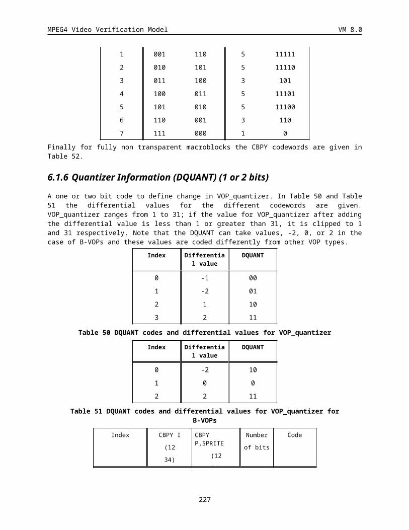
MPEG4 Video Verification Model VM 8.0
13APPENDIX H: CORE EXPERIMENTS The following is a summary list of core experiments. For more information, please refer to the appropriate documents as listed below. This list is to be updated in the next release of the VM.
No. Core Experiment
N3
P6
P8
P9
P12
P13
P14
Prediction (ISO/IEC JTC1/SC29/WG11/N1588)
Dynamic Sprites
Multimode warping prediction
Motion + aliasing compensation
Motion Compensated Prediction using Quadtree Segmentation and Polynomial Motion Fields.
B VOP improvements
Reduced Resolution Update
Interlaced coding tools
T1
T3
T14
T15
T16
Frame Texture Coding (ISO/IEC JTC1/SC29/WG11/N1588)
Wavelet Coding of I Pictures
Matching Pursuits Coding of Prediction Errors
VLC improvements: intra and inter
12 bit video
AC/DC prediction
S4
S hape and Alpha Channel Coding (ISO/IEC JTC1/SC29/WG11/N1644)
Comparison of Shape coding Techniques
O3
O4
O10
Object/Region Texture Coding (ISO/IEC JTC1/SC29/WG11/N1645)
Object Wavelet for Texture Coding Mode
Modified Shape Adaptive DCT
Boundary Block Merging
E4
E8
Error Resilient Core Experiments (ISO/IEC JTC1/SC29/WG11/N1586)
Core Experiment on Back Channel Signaling
Core Experiment on Data Partitioning for Error Resilience
C1.1
B1.1
H1
Bandwidth and Complexity Scaling (ISO/IEC JTC1/SC29/WG11/N1587)
Optimization of Object Based Temporal Scalability
Optimization of Spatial Scalability and Object Based Spatial Scalability
Investigations into hybrid scalability
M1
M2
Multi-view, Model Manipulation and Others (ISO/IEC JTC1/SC29/WG11/N1587 )
Mismatch Corrected Stereo/Multiview Coding
2-D Triangle Mesh for Object/Content Manipulation
Pre-, Mid-, and Post-processing (ISO/IEC JTC1/SC29/WG11/N1587)
227
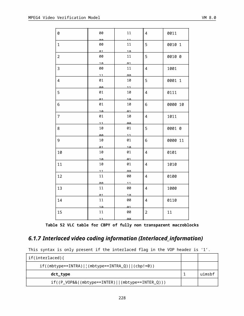
MPEG4 Video Verification Model VM 8.0
N1
N2
Comparison of Coding Noise Removal Techniques
Comparison of Automatic Segmentation Techniques
Z1
Z2
Z3
Z4
SNHC Generic Object Coding (ISO/IEC JTC1/SC29/WG11/N1555)
Coding efficiency of texture
Quality,spatial and view-dependent scalability
Coding of 3D mesh
Coding of animated 2D mesh
Table 72 List of Core Experiments
228
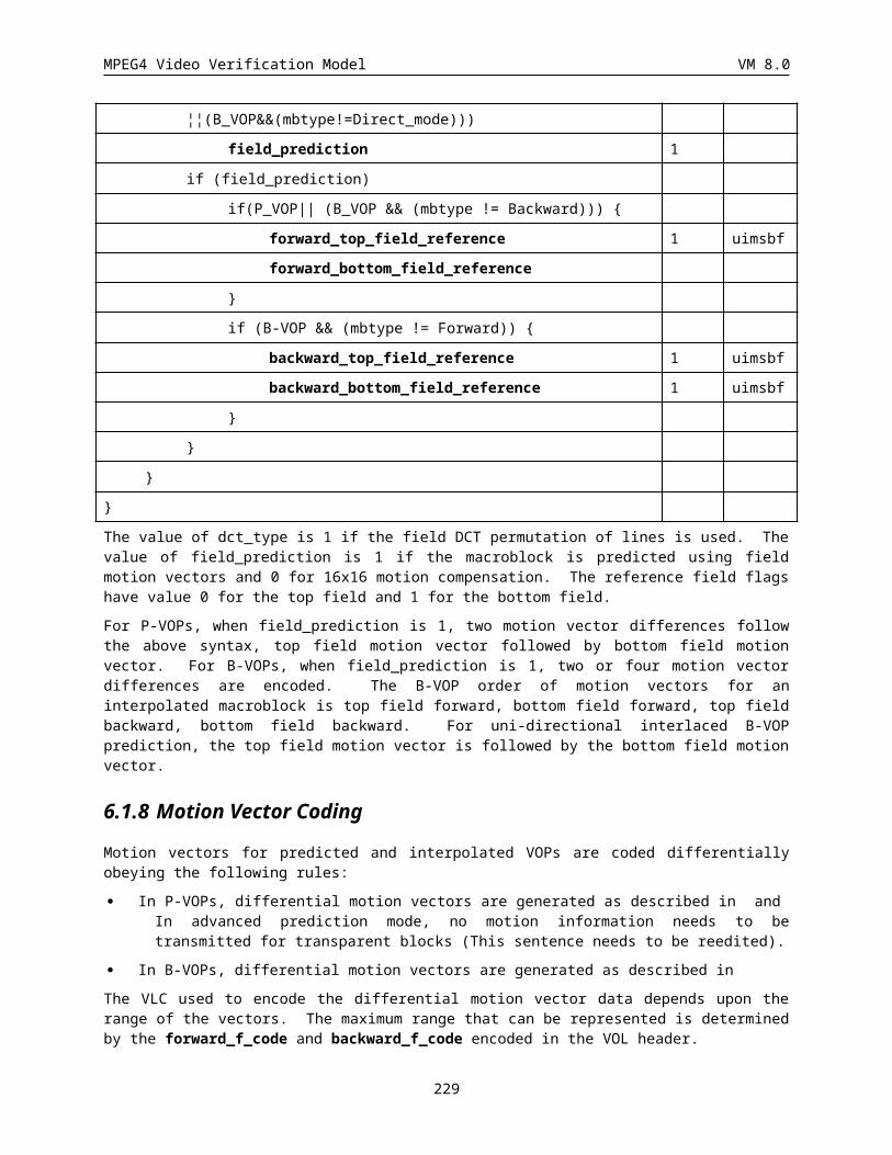
MPEG4 Video Verification Model VM 8.0
14 VERSION 2
14.1 Coding Arbitrarily Shaped Texture
Shape adaptive wavelet (SA-Wavelet) coding is used for coding arbitrarily shaped texture. SA-Wavelet coding is different from the regular wavelet coding mainly in its treatment of the boundaries of arbitrarily shaped texture. SA-Wavelet coding ensures that the number of wavelet coefficients to be coded is exactly the same as the number of pixels in the arbitrarily shaped region and coding efficiency for the boundaries is the same as that for the middle of the region. SA-Wavelet coding includes rectangular boundaries as a special case and it becomes the regular wavelet coding when the boundary is rectangular.
14.1.1 Shape Adaptive Wavelet Transform
Shape information of an arbitrarily shaped region is used in performing SA-Wavelet transform. The (9,3) biorthogonal wavelet filter given in 3.10.2 is used. Let low-pass filter coefficients be {h4, h3, h2, h1, h0, h1, h2, h3, h4} and high-pass filter coefficients be {g1, g0, g1}. SA-Wavelet transform can be described as the following steps:
1. Within each region, use shape information to identify the first row of pixels belonging to the region and the first segment of consecutive pixels in the row. Let the start position of this segment be start and thelength of this segment be length.
2. If length == 1, this pixel is scaled by sqrt(2) and put into the corresponding position start/2 in low-pass band. Otherwise, the following steps are performed.
3. If length is even and start is even, wavelet filtering is performed on this segment with Type-B symmetric extension on both leading and trailing boundaries for analysis in the same way as specified in Table 14. The length/2 low pass coefficients are obtained by subsampling the low pass filtering results at even number positions relative to start, and are put into low-pass band starting from position start/2. The length/2 high-pass coefficients are obtained by subsampling the high pass filtering results at odd number positions relative to start, and are put in high pass band starting from position start/2. The corresponding synthesis uses Type-B leading and Type-A trailing boundaries for low-pass and Type-A leading and Type-B trailing boundaries for high-pass as specified in Table 15. The following example illustrates this process in detail:
LOW PASS:
signal: a2 a3 a2 a1 | a0 a1 a2 a3 | a2 a1 a0
<------------> <------------> <-------->
extension: Type B ext. original Type B ext.
229
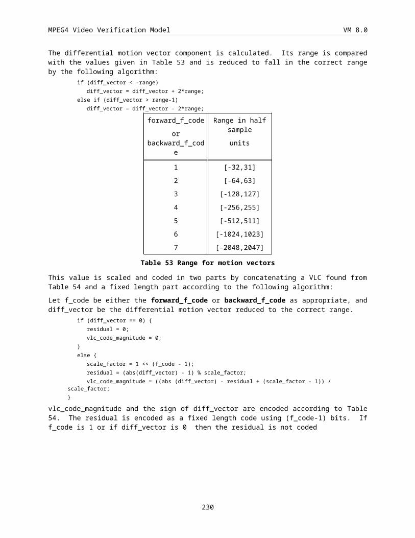
MPEG4 Video Verification Model VM 8.0
low pass filt.: h4 h3 h2 h1 h0 h1 h2 h3 h4
... h4 h3 h2 h1 h0 h1 h2 h3 h4
...
Transformed: x0 x1 | x0 x1 | x1 x0
<----------> <------------> <--------->
Type B ext. low pass band type A ext.
HIGH PASS:
signal: a2 a3 a2 a1 | a0 a1 a2 a3 | a2 a1 a0
<------------> <------------> <-------->
extension: Type B ext. original Type B ext.
high pass filt.: g1 g0 g1
... g1 g0 g1
...
Transformed: y1 y0 | y0 y1 | y0
<--------> <---------> <--------->
Type A ext. high pass band type B ext.
4. If length is even and start is odd, wavelet filtering is performed on this segment with Type-B symmetric extension on both leading and trailing boundaries for analysis. The length/2 low pass coefficients are obtained by subsampling the low pass filtering results at even number positions starting from start, and are put into low pass band starting from postion (start+1)/2. The length/2 high pass coefficients are obtained by subsampling the high pass filtering results at odd number positions starting from start, and are put in high pass band starting from position start/2. The corresponding synthesis uses Type-A leading and Type-B trailing boundaries for low-pass and Type-B leading and Type-A trailing boundaries for high-pass. The following example illustrates this process in detail.
LOW PASS:
signal: a3 a4 a3 a2 | a1 a2 a3 a4 | a3 a2 a1 a2
<------------> <------------> <------------>
extension: Type B ext. original Type B ext.
low pass filt.: h4 h3 h2 h1 h0 h1 h2 h3 h4
230
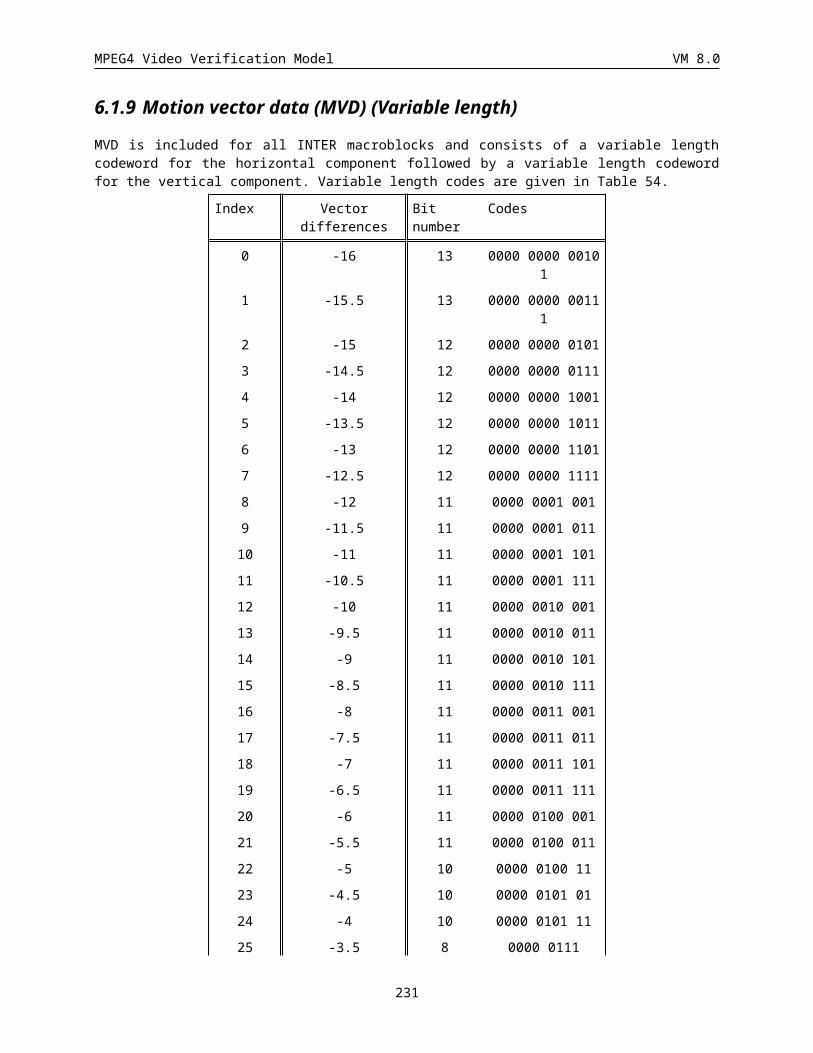
MPEG4 Video Verification Model VM 8.0
... h4 h3 h2 h1 h0 h1 h2 h3 h4
...
Transformed: x0 x1 | x1 x2 | x1 x0
<--------> <----------> <--------->
Type A ext. low pass band type B ext.
HIGH PASS:
signal: a3 a4 a3 a2 | a1 a2 a3 a4 | a3 a2 a1 a2
<------------> <------------> <------------>
extension: Type B ext. original Type B ext.
high pass filt.: g1 g0 g1
... g1 g0 g1
...
Transformed: y1 y1 | y0 y1 | y1 y0
<--------> <---------> <--------->
Type B ext. high pass band type A ext.
5. If length is odd and start is even, wavelet filtering is performed on this segment with Type-B symmetric extension on both leading and trailing boundaries for analysis. The (length+1)/2 low pass coefficients are obtained by subsampling the low pass filtering results at even number positions starting from start, and are put into low pass band starting from postion start/2. The length/2 high pass coefficients are obtained by subsampling the high pass filtering results at odd number positions starting from start, and are put in high pass band starting from position start/2. The corresponding synthesis uses both Type-B leading and trailing boundaries for low-pass and both Type-A leading and trailing boundaries for high-pass. The following example illustrates this process in detail.
LOW PASS:
signal: a2 a3 a2 a1 | a0 a1 a2 a3 a4 | a3 a2 a1 a0
<------------> <-----------------> <------------>
extension: Type B ext. original Type B ext.
low pass filt.: h4 h3 h2 h1 h0 h1 h2 h3 h4
... h4 h3 h2 h1 h0 h1 h2 h3 h4
231
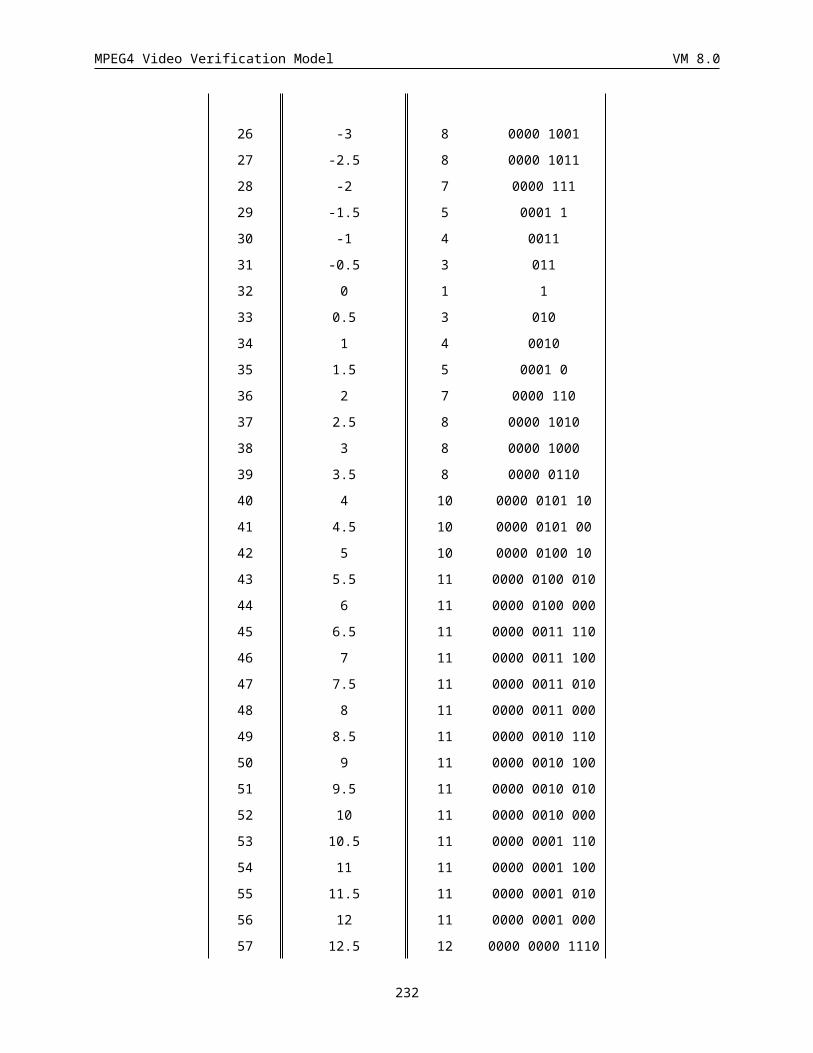
MPEG4 Video Verification Model VM 8.0
... h4 h3 h2 h1 h0 h1 h2 h3 h4
...
Transformed: x0 x1 | x0 x1 x2 | x1 x0
<----------> <-----------------> <--------->
Type B ext. low pass band type B ext.
HIGH PASS:
signal: a2 a3 a2 a1 | a0 a1 a2 a3 a4 | a3 a2 a1 a0
<------------> <----------------> <------------>
extension: Type B ext. original Type B ext.
high pass filt.: g1 g0 g1
... g1 g0 g1
...
Transformed: y1 y0 | y0 y1 | y1
<--------> <---------> <--------->
Type A ext. high pass band type A ext.
6. If length is odd and start is odd, wavelet filtering is performed on this segment with Type-B symmetric extension on both leading and trailing boundaries for analysis. The length/2 low pass coefficients are obtained by subsampling the low pass filtering results at even number positions starting from start, and are put into low pass band starting from postion (start+1)/2. The (length+1)/2 high pass coefficients are obtained by subsampling the high pass filtering results at odd number positions starting from start, and are put in high pass band starting from position start/2. The corresponding synthesis uses both Type-B leading and trailing boundaries for low-pass and both Type-A leading and trailing boundaries for high-pass. The following example illustrates this process in detail.
LOW PASS:
signal: a3 a4 a3 a2 | a1 a2 a3 a4 a5 | a4 a3 a2 a1
<------------> <----------------> <------------>
extension: Type B ext. original Type B ext.
low pass filt.: h4 h3 h2 h1 h0 h1 h2 h3 h4
... h4 h3 h2 h1 h0 h1 h2 h3 h4
...
Transformed: x0 x1 | x1 x2 | x2 x1
232
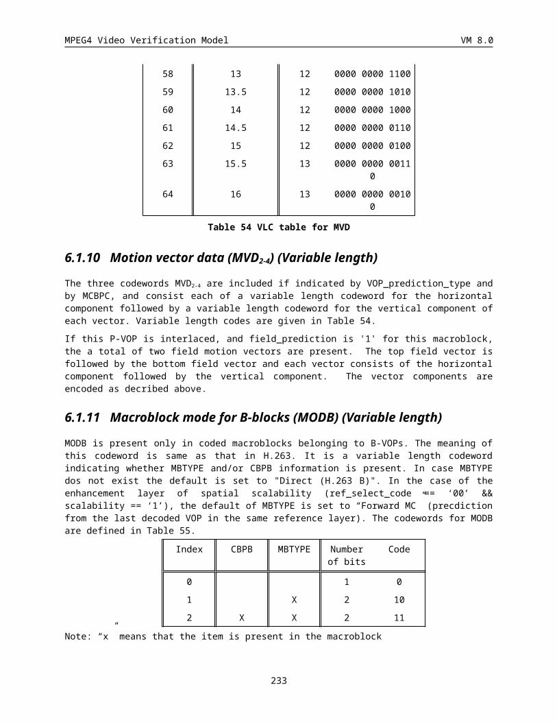
MPEG4 Video Verification Model VM 8.0
<--------> <----------> <---------->
Type A ext. low pass band type A ext.
HIGH PASS:
signal: a3 a4 a3 a2 | a1 a2 a3 a4 a5 | a4 a3 a2 a1
<------------> <----------------> <------------>
extension: Type B ext. original Type B ext.
high pass filt.: g1 g0 g1
... g1 g0 g1
... g1 g0 g1
...
Transformed: y1 y1 | y0 y1 y2 | y1 y0
<--------> <-----------------> <-->
Type B ext. high pass band type B ext.
7. Repeat the above operations for the next segment of consecutive pixels in the same row.
8. Repeat the above operations for the next row of the region.
9. Repeat the above operations for each column of the horizontally low-pass and high-pass region.
10. Repeat the above operations on the LL object until the number of decomposition level is reached.
The mask associated with the arbitrarily shaped region is decomposed into the corresponding wavelet trees.
14.1.2 Modified Zero-Tree Coding According to Decomposed Mask
Coding the SA-Wavelet coefficients is the same as coding regular wavelet coefficients except a modification is needed to handle partial wavelet trees that have wavelet coefficients corresponding to the pixels out of the shape boundary. Such wavelet coefficients are called out-nodes of the wavelet trees. Coding of the lowest band is the same as specifed in 3.10.3 with out-nodes not coded. The wavelet trees are formed in the same way as in the regular zero-tree coding. Coding of the higher bands is the same as specified in 3.10.4 except the modifications described below to handle the out-nodes. For any wavelet trees without out-nodes, the regular zero-tree coding is applied. For a partial tree, a minor modification to the regular zero-tree coding is needed to deal with the out-nodes. If an entire branch of a partial tree has out-nodes only, no coding is needed for this branch because the shape information is available to the decoder to indicate this case. If a parent node is not an out-node, all the children out-nodes are set to zero so that the out-node does not affect the status of the parent node as the zero-tree root or valued zero-tree root. At the decoder, the shape information is used to identify such zero values as out-nodes. If the parent node is an out-node and not all of its children are out-nodes, there are two possible cases. The first case is that some of its children are not out-nodes but they are all zeros. This case is treated as a zero-tree root
233
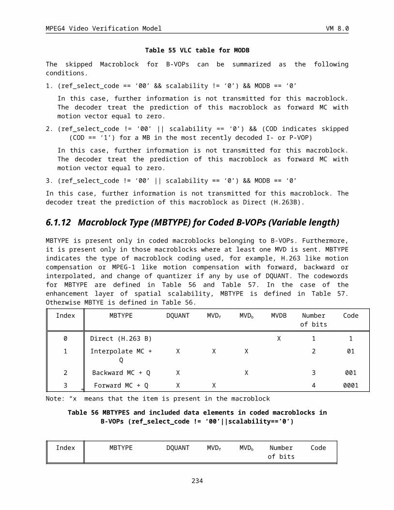
MPEG4 Video Verification Model VM 8.0
and there is no need to go down the tree. The shape information indicates which children are zeros and which ones are out-nodes. The second case is that some of its children are not out-nodes and at least one of such nodes is non-zero. In this case, the out-node parent is set to zero and the shape information helps decoder know that this is an out-node, and coding continues further down the tree. There is no need to use a separate symbol for any out-nodes.
14.1.3 Texture Object Layer Class
14.1.3.1 Texture Object Layer
Syntax No. of bits NoteTextureObjectLayer() {
texture_object_layer_start_code sc+4=28
texture_object_layer_id 4
texture_object_layer_shape 2
if(texture_object_layer_shape == ‘00’) {
texture_object_layer_width 16
texture_object_layer_height
wavelet_transform()
16
} else if (texture_object_layer_shape == ‘01’) {
shape_coding()
sa_wavelet_transform()
}
wavelet_decomposition_levels 8
Y_mean 8
U_mean 8
V_mean 8
Quant_DC_Y 8
Quant_DC_UV 8
for (Y, U, V){
lowest_subband_bitstream_length 16
band_offset 8 (or more)
band_max_value 8 (or more)
if(texture_object_layer_shape == ‘00’) {
lowest_subaband_texture_coding()
} else if(texture_object_layer_shape == ‘01’) {
lowest_subband_texture_sa_coding()
}
}
234
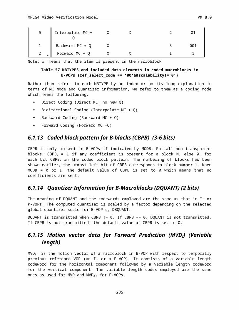
MPEG4 Video Verification Model VM 8.0
spatial_scalability_levels 5
quantization_type 2
SNR_length_enable 1
for (Y, U, V){
for (i=0; i <spatial_scalability_levels; i++)
spatial_bitstream_length 24
if (quantization_type == 0){
Quant 8 skipped for V
if(texture_object_layer_shape == ‘00’) {
wavelet_zero_tree_coding()
} else if(texture_object_layer_shape == ‘01’) {
wavelet_zero_tree_sa_coding()
}
}
else if ( quantization_type == 1){
SNR_Scalability_Levels 5 skipped for U,V
for(i=0;i<SNR_scalability_levels; i++){
Quant 8 skipped for V
SNR_all_zero 1
if( all_zero_flg == 0){
if(SNR_length_enable == 1)
SNR_bitstream_length 16 or more refer to description
if(texture_object_layer_shape == ‘00’) {
wavelet_zero_tree_coding()
} else if(texture_object_layer_shape == ‘01’) {
wavelet_zero_tree_sa_coding()
}
}
}
}
else {
Quant 16
if (SNR_length_enable == 1)
SNR_bitstream_length 16 or more refer to description
if(texture_object_layer_shape == ‘00’) {
235
MPEG4 Video Verification Model VM 8.0
wavelet_zero_tree_coding()
} else if(texture_object_layer_shape == ‘01’) {
wavelet_zero_tree_sa_coding()
}
}
}
next_start_code()
}
14.2 Scalable shape coding
14.2.1 Spatial Scalable Coding Figure 1 shows an example of spatial scalable coding. As shown in the figure, the enhancement layer is built from the base layer (I-VOP) like a P-VOP. For the base layer (P-VOP), the enhancement layer is built like a B-VOP.
I P P
BBP
Figure 1. An Example of Spatial Scalable Coding
14.2.1.1 Base Layer CodingThe base layer is encoded as the same way as non-scalable binary shape coding (i.e. CAE). VOP_CR may be utilized when there is a resolution difference between shape and texture.
14.2.1.2 Modes for Enhancement Layer MBs For B-VOP in enhancement layer in Figure 1, there are four modes;
236
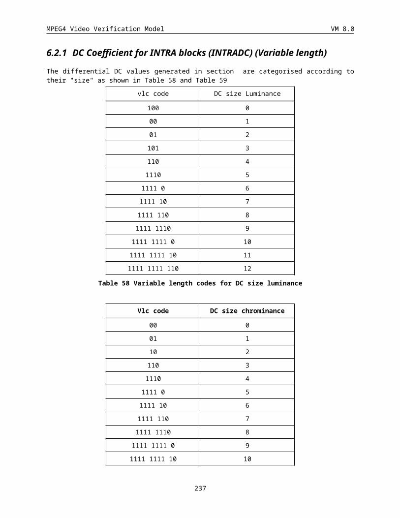
MPEG4 Video Verification Model VM 8.0
(1) Shape_mode = “intra not coded”
(2) Shape_mode = “intra coded”
(3) Shape_mode = “inter not coded”
(4) Shape_mode = “inter coded”
· When the Shape_mode = “intra coded”, the MB is predicted from the collocated MB in the lower layer and is encoded as described in Section
· The Shape_mode = “intra not coded” means that “all_zero”1, “all_255”, or the error of the predicted MB from the lower layer is less than the threshold2. At the decoder, if the corresponding samples of the collocated MB in the lower layer have only the value 0 (or 255), then the MB in the current layer is "all_zero" (or "all_255"). Otherwise, the predicted MB (using the method in Section 1.5) from the lower layer is used as the MB in the current layer.
· For two “inter” modes, no motion vector is transmitted for enhancement layer MBs. The corresponding motion vector can be utilized from the lower layer. If the MB in the lower layer is “intra” mode, the value of the motion vector is set to zero. If the error of the predicted MB from the previous VOP is less than the threshold6 , then the MB is “inter not coded” mode.
· For P-VOP in enhancement layer in Figure 1, there are only two modes, “intra coded” and “intra not coded”, and they are coded by 1 bit.(if the mode is “intra coded”, then the code is ‘0’, otherwise ‘1’)
14.2.1.2.1 Coding the mode information for enhancement layer MBs
In order to encode/decode the mode information, the collocated MB of the lower layer is examined. Based on the result of this analysis, the following VLC table is used for encoding the shape mode.
The Lower Layer The Enhancement Layer
(1) (2) (3) (4)
(1) 0 10 110 111
(2) 110 0 10 111
(3) 110 10 0 111
(4) 111 0 111 10
Note that the numbers (1)-(4) in these tables correspond to the shape modes given in the list above. When the lower layer is the base layer, "MVDs==0&&No Update"and "MVDs!=0&&No Update", "all_0" and "all_255", and "MVDs==0&&interCAE" and "MVDs!=0&&interCAE" modes are included in mode (3), (1), and (4), respectively
1 This mode is not used, but its meaning is the same with for the base layer coding.2 This decision is the same with for the base layer coding.6
237
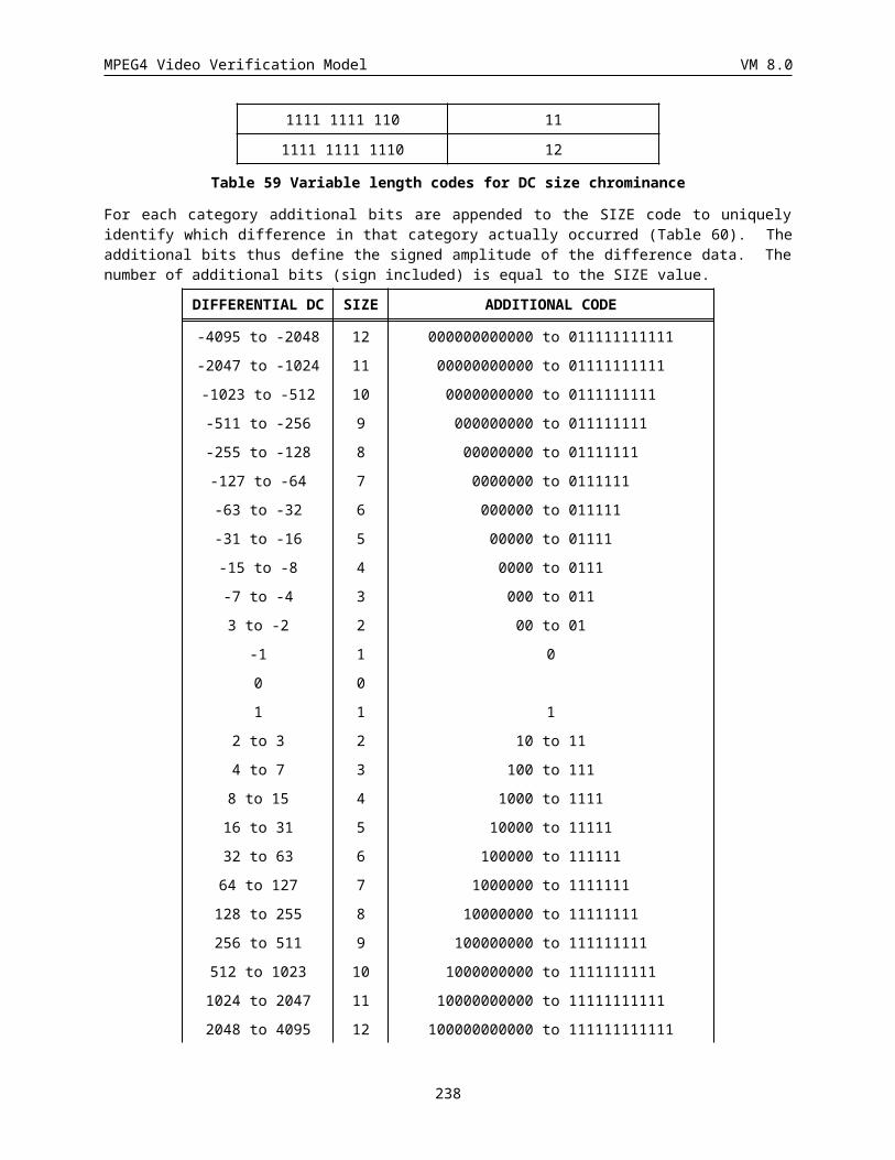
MPEG4 Video Verification Model VM 8.0
14.2.1.2.2 Mode Decisions for Enhancement Layer MBs
There are two new decisions used in the coding of enhancement layer MBs in P-VOPs and B-VOPs.
1. Not Coded/Coded Decision
There are 2 modes which involve prediction without coding i.e. (3) with INTER prediction and (1) with INTRA prediction. In the decision process, it is firstly ascertained whether "all_zero" or "all_255" in “intra not coded” can be used.
Condition1 = “intra not coded” ( "all_0" or "all_255" ) may be used.
It is then ascertained whether “inter not coded” can be used. This decision is performed in the same way as for the base layer and relies on the value of alpha_th.
Condition2 = “inter not coded” may be used.
Lastly, it is ascertained whether “intra not coded”, except for "all_0" and "all_255", can be used. A MB can be encoded as “intra not coded” if the prediction from lower layer yields error PBs with value less than 16xalpha_th.
Condition3 = “intra not coded”, except for "all_0" and "all_255", may be used.
if(Condition1) MB is coded as “intra not coded”;
else if(Condition2) MB is coded as“inter not coded”;
else if(Condition3) MB is coded as“intra not coded”;
else MB is coded by one of the other “coded” modes.
2. Intra coded/Inter coded decision
If an enhancement MB is coded, it may be coded as “intra coded” or “inter coded”. Both methods are applied and the shortest code is sent.
14.2.1.3 Enhancement Layer Coding with the Base Layer (I-VOP)
14.2.1.3.1 Down SamplingIn order to achieve the spatial scalability, a BAB is firstly downsampled into 8x8 subblock. Figure 2 Shows the subsampling process. In every 2x2 pixel block, the bottom-right pixel is chosen to be the subsampled pixel.
SubXi/2,j/2 = Xi,j, (i, j = 0, 2, 4, …, 14)
238
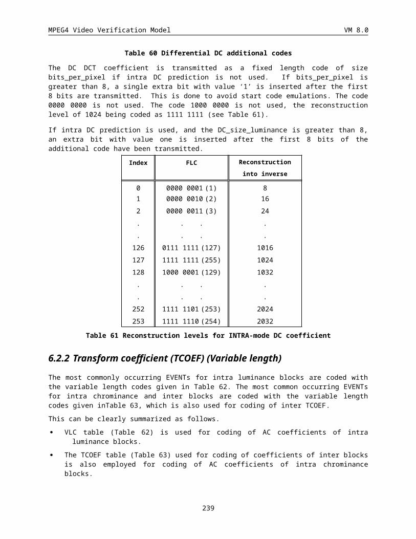
MPEG4 Video Verification Model VM 8.0
Original BAB Subsampled BAB
Figure 2. An Example of BAB Subsampling
14.2.1.3.2 Scan InterleavingThe spatial (or resolution) scalability can be easily sought by incorporating the so-called scan interleaving (SI) method. In SI, every other scanlines are encoded by the prediction from the neighboring two scan lines as shown in Fig. 13. In the figure, you can use the upper and lower neighboring pixel values for encoding the current pixel value. If the two neighboring pixels are the same colors, it is very likely that the current pixel is also the same color. If two neighbor pixels are different from each other, you need to encode the current pixel information: we call it a transitional sample. Even if the two upper and lower neighboring pixels are the same, the current pixel may be different in a relatively small probability: we call it a exceptional sample. Hence, each enhancement layer yields two types of data: transitional sample data (TSD) and exceptional sample data (ESD). SI modules are paired for the purpose of vertical and horizontal scanning alternatively.
Reference Scan Line
Reference Scan Line
Reference Scan Line
Coded Scan Line
Coded Scan Line
: Level Transition Case : Exceptional Case
239
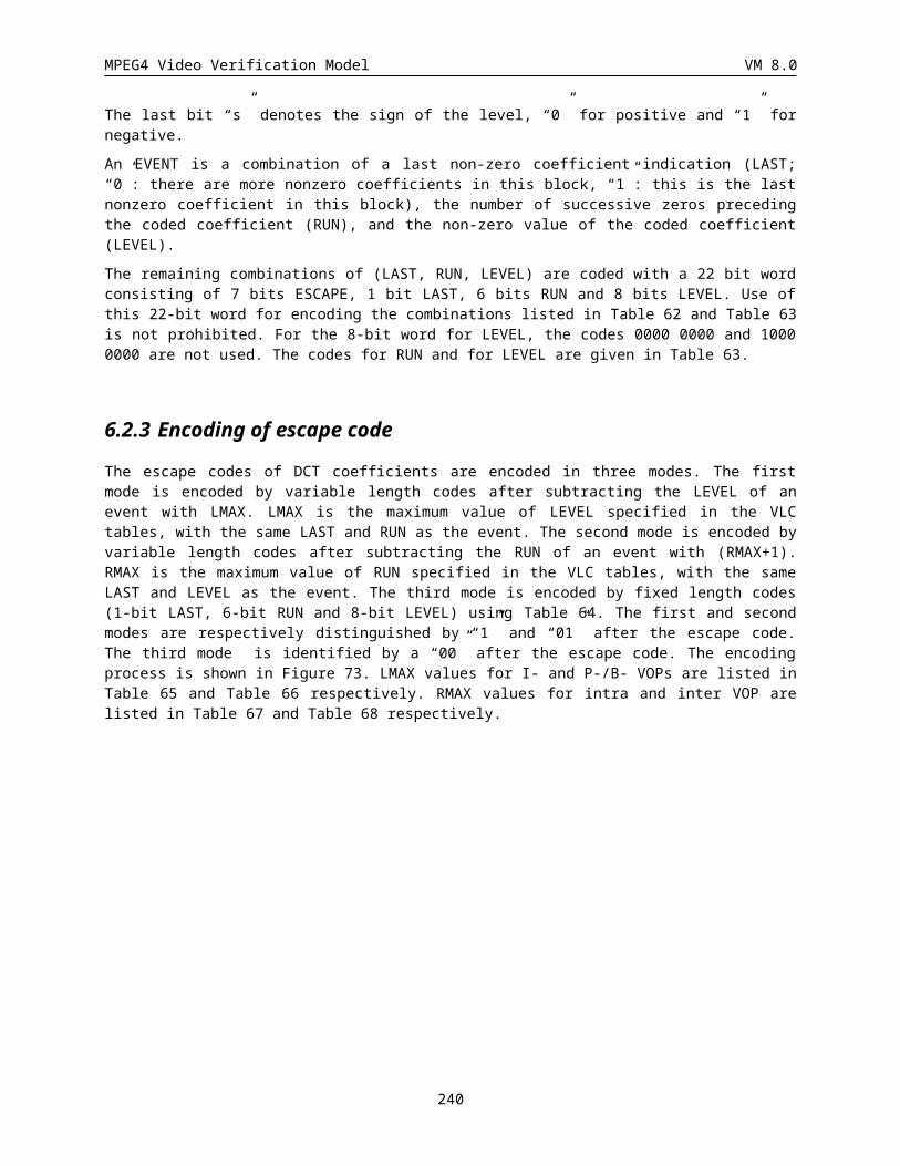
MPEG4 Video Verification Model VM 8.0
Figure 3. Scan Interleaving for Scalable Coding: an Example.
14.2.1.3.3 Transitional Sample Only BAB EncodingDepending on the scanning direction, the context information for the current pixel is decided as shown in Fig. 4. By using neighboring 7 contexts, the current pixel is arithmetic encoded as in CAE, such that:
1. Compute a context number.
2. Index a probability table using the context number.
3. Use the indexed probability to drive an arithmetic encoder.
14.2.1.3.4 Exceptional Sample Included BAB Encoding When there is any exceptional sample in a BAB, all the pixels (both transitional and exceptional) are encoded in a raster scan order using the contexts in Fig. 4. The encoding is the same procedure as above (Section ).
Horizontal Scanning
X
C0 C1 C2
C3
C4 C6C5 Y
C0 C1 C2
C3 C4
C5 C6
Vertical Scanning
Figure 4. The context information at different scanning.
14.2.1.3.5 Determination of the scanning orderThe scanning order of encoded pixels can be determined to be HV scanning or VH scanning. For HV scanning horizontal scanning is performed first and then vertical scanning. For VH scanning vertical scanning is performed first. The order of scanning is determined by the base layer information. Normally HV scanning is selected for the regular scanning order, except when the scale between the layers is square times (i.e. 200x300 à 400x600). This time we efficiently choose the scanning order of encoded pixels in the enhancement layer by the base layer shape information.
The top and left borders are extended with neighboring pixels like Fig. 5. If an extended border is outside VOP, the pixel values of the extended border are set to zero. Two counts, NL and NU are calculated (NL: the number of pixels which have different values from the left neighboring pixel value; NU: the number of pixels which have different values from the upper neighboring value). If NU is greater than NL, the scanning order is set to VH scanning and otherwise to HV scanning. Fig. 6 shows one example. In the figure, NL is 8 and NU is 6. The scanning order is set to HV scanning because NL is larger than NU.
240

MPEG4 Video Verification Model VM 8.0
top border
left border
original block
Figure 5. Extension of border pixels.
8pixels6 pixelsFigure 6. Example of the scanning order determination
14.2.1.4 Enhancement Layer Coding with the Base Layer (P-VOP)For the enhancement layer with P-VOP or B-VOP base layer, the context information in Fig. 7 is utilized. The encoding of the current pixel is done in the same way as CAE.
241
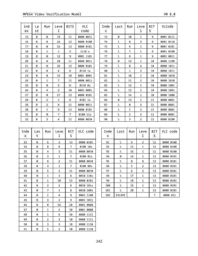
MPEG4 Video Verification Model VM 8.0
)N
Figure 7. INTER Templates and Context Construction.
14.2.2 Prediction with the context probability tables In the case that shape is encoded QCIF and texture is encoded CIF, we need to extend the current shape based on what we have: known pixels and unknown pixels. These unknown pixels can be predicted by the probability table values based on the contexts shown in Fig. 4 and 7. Likewise, for "intra not coded" mode, the prediction of MB in current layer from the lower layer is needed. For this, the probability table values based on the context shown in Figure 4 is used. The context number is firstly calculated. If the probability of its context number is greater than, or equal to 0.5 , then it is predicted as 0. Otherwise, 1 is used as prediction value.
14.2.3 Quality(SNR) Scalable Coding Quality Scalability can be easily sought by spatial scalability. One can use alpha_th to achieve different levels of granularity. In quality scalable coding, we can achieve the enhancement of only an important part of the shape by coding relatively larger number of enhancement layers for macroblocks belonging to this important part. For instance, part of the shape corresponding to head in a video object containing head and shoulders of a human can be identified as the important part. Non-important parts of the shape can be coded without enhancement by invoking the “intra_not_coded” mode at the encoder.
14.2.4 Region- (or Content-) based Scalable CodingRegion- (or Content-) based scalability of shape can be simply implemented by CAE. This mode is set when scalability is ON and enhancement_type is ON. This means that only a special region of shape and texture will be enhanced. This region is CAE encoded. The proper syntax is reflected in Section .
14.2.5 Syntax
14.2.5.1 Video Object Layer
scalability 1
if (scalability){
ref_layer_id 4
242
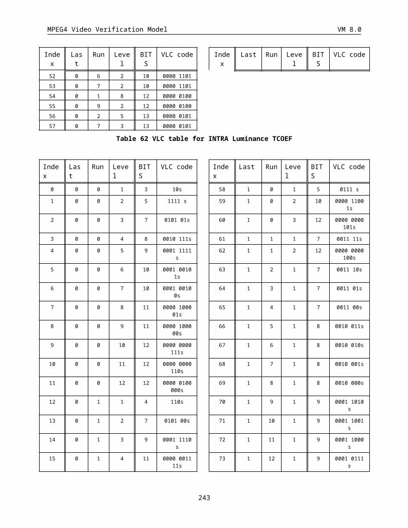
MPEG4 Video Verification Model VM 8.0
use_ref_shape 1
use_ref_texture 1
shape_hor_sampling_factor 1
shape_vert_sampling_factor 1
ref_layer_sampling_direc 1
hor_sampling_factor_n 5
hor_sampling_factor_m 5
vert_sampling_factor_n 5
vert_sampling_factor_n 5
enhancement_type 1
}
use_ref_shape
When this one bit is set, no update for shape is done. Instead, the available shape in the layer ref_layer_id will be used.
use_ref_texture
When this one bit is set, no update for texture is done. Instead, the available texture in the layer ref_layer_id will be used.
shape_hor_sampling_factor, shape_vert_sampling_factor
shape_hor_sampling_factor and shape_vert_sampling_factor denote the sampling factors of shape in horizontal and vertical directions, respectively..
14.2.5.2 Shape Coding
Syntax No. of bitsbinary_shape_coding() { if(!scalability || (scalability && enhancement_type) ){ if (video_object_layer_shape != '00') { do if ( Shape_mode = “MVDs!=0 && NotCoded” || Shape_mode=”interCAE && MVDs!=0”) MVDs 3-36 if (Shape_mode = ”intraCAE”
|| Shape_mode=”interCAE && MVDs==0”
|| Shape_mode=”interCAE && MVDs!=0” ) { if (change_CR_disable==”0”) CR 1-2
243
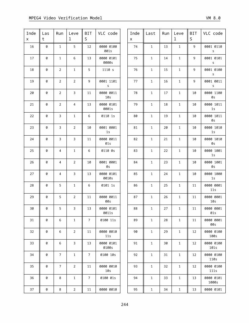
MPEG4 Video Verification Model VM 8.0
ST 1 BAC } } while (count of macroblock != total number of macroblocks) } else if (scalability && !enhancement_type) enh_layer_shape_coding();}
enh_layer_shape_coding()
For spatial scalable coding, or when scalability is set and enhancement_type is '0', enh_layer_shape_coding() is performed.
14.2.5.2.1 Enhancement Layer Shape Coding
Syntax No. of bitsenh_layer_shape_coding() { if (video_object_layer_shape != '00') { do if (Shape_mode == ”intra_coded” || Shape_mode==”inter_coded”) { ST 1 BAC_TRANS } while (count of macroblock != total number of macroblocks) }
ST
If shape_mode == "intra coded", ST is set when it contains only transitional samples, whereas ST is unset when all pixels are coded. If shape mode == 'inter coded", the usage is the same as CAE.
BAC_TRANS
If ST is '1', it is the bitstream for transitional pels. Otherwise the usage is the same as BAC.
14.2.6 APPENDIX A: Probability TablesUSInt scaleable_shape_Intra[256]={
244
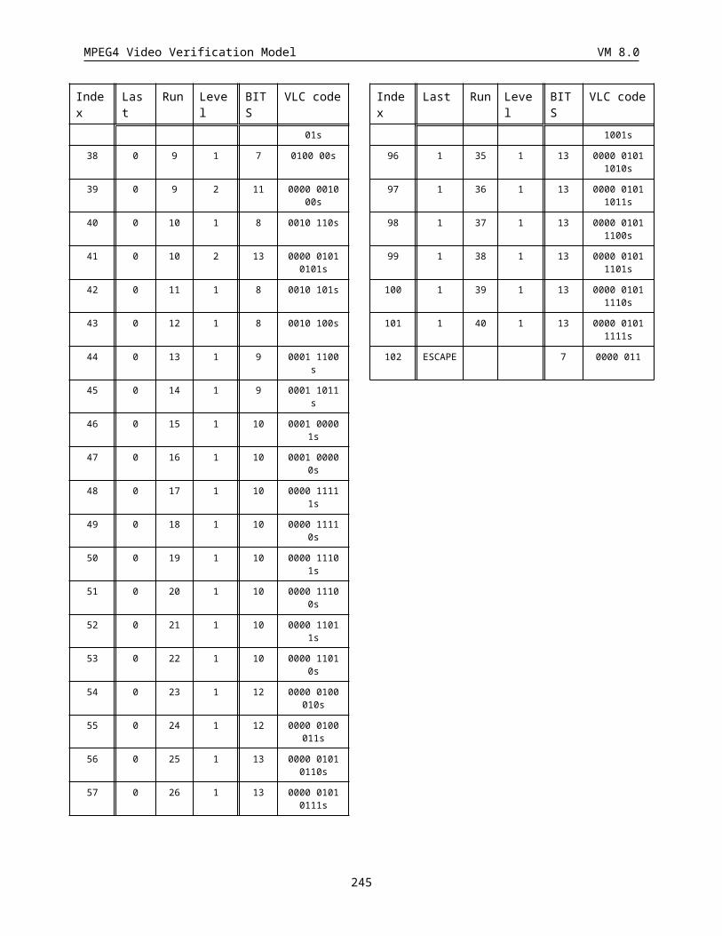
MPEG4 Video Verification Model VM 8.0
65476, 64428, 62211, 63560, 52253, 58271, 38098, 31981, 50087, 41042,
54620, 31532, 8382, 10754, 3844, 6917, 63834, 50444, 50140, 63043,
58093, 45146, 36768, 13351, 17594, 28777, 39830, 38719, 9768, 21447,
12340, 9786, 60461, 41489, 27433, 53893, 47246, 11415, 13754, 24965,
51620, 28011, 11973, 29709, 13878, 22794, 24385, 1558, 57065, 41918,
25259, 55117, 48064, 12960, 19929, 5937, 25730, 22366, 5204, 32865,
3415, 14814, 6634, 1155, 64444, 62907, 56337, 63144, 38112, 56527,
40247, 37088, 60326, 45675, 51248, 15151, 18868, 43723, 14757, 11721,
62436, 50971, 51738, 59767, 49927, 50675, 38182, 24724, 48447, 47316,
56628, 36336, 12264, 25893, 24243, 5358, 58717, 56646, 48302, 60515,
36497, 26959, 43579, 40280, 54092, 20741, 10891, 7504, 8109, 30840,
6772, 4090, 59810, 61410, 53216, 64127, 32344, 12462, 23132, 19270,
32232, 24774, 9615, 17750, 1714, 6539, 3237, 152, 65510, 63321,
63851, 62223, 64959, 62202, 63637, 48019, 57072, 33553, 37041, 9527,
53190, 50479, 54232, 12855, 62779, 63980, 49604, 31847, 57591, 64385,
40657, 8402, 33878, 54743, 17873, 8707, 34470, 54322, 16702, 2192,
58325, 48447, 7345, 31317, 45687, 44236, 16685, 24144, 34327, 18724,
10591, 24965, 9247, 7281, 3144, 5921, 59349, 33539, 11447, 5543,
58082, 48995, 35630, 10653, 7123, 15893, 23830, 800, 3491, 15792,
8930, 905, 65209, 63939, 52634, 62194, 64937, 53948, 60081, 46851,
56157, 50930, 35498, 24655, 56331, 59318, 32209, 6872, 59172, 64273,
46724, 41200, 53619, 59022, 37941, 20529, 55026, 52858, 26402, 45073,
57740, 55485, 20533, 6288, 64286, 55438, 16454, 55656, 61175, 45874,
28536, 53762, 58056, 21895, 5482, 39352, 32635, 21633, 2137, 4016,
58490, 14100, 18724, 10461, 53459, 15490, 57992, 15128, 12034, 4340,
6761, 1859, 5794, 6785, 2412, 35
};
USInt scaleable_shape_SI_mode[1] = { 59808 }
14.3 Matching pursuit inter texture coding mode
14.3.1 Introduction to Matching Pursuit mode
245
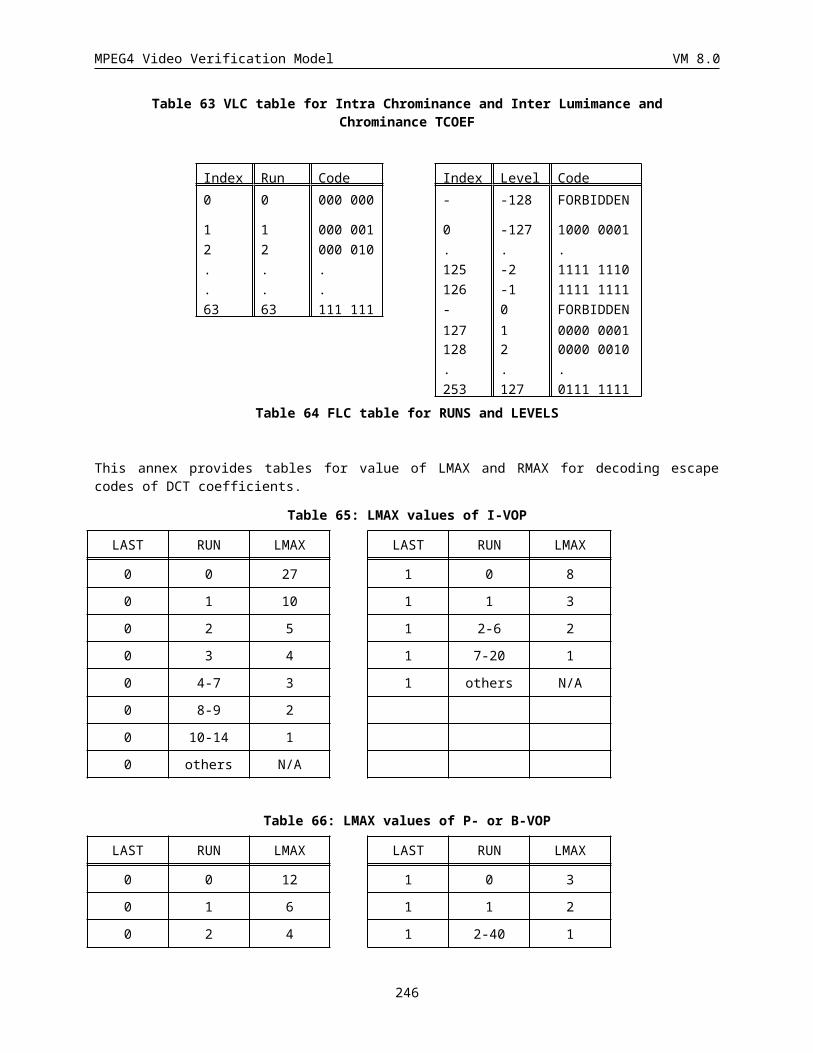
MPEG4 Video Verification Model VM 8.0
Matching pursuit (MP) is an over-complete expansion technique that can be used in place of the DCT for prediction error coding. Matching pursuit uses an over-complete 2-D Gabor dictionary to code motion prediction errors. This dictionary is extremely redundant, containing 400 2-D basis shapes, each of which may exist at any integer-pixel location in the coded residual image. MP insures that each coded basis function is well-matched to structures in the residual signal.
14.3.2 INTRA Frame Coding
The INTRA frame coding is the same as the one used in the DCT mode.
14.3.3 Motion Compensation
The motion estimation modes are the same as for the DCT mode.
There is one deviation from the DCT mode motion: in the way INTRA blocks are handled. In DCT mode, the prediction for INTRA blocks are reset to zero and the blocks are later coded using DCT. In MP mode, the matching pursuit algorithm is also used to fill in the INTRA block details. At the motion compensation stage, MP mode encoder sends the DC coefficients of the six macroblock sub-blocks (four luminance and two chrominance sub-blocks). These are quantized to five bits and sent along with the motion information. The DC values are then windowed by the DCT mode overlapping motion window and combined with the prediction image before the residual coding stage.
14.3.4 Prediction Error Encoding Using Matching Pursuit
After the prediction image is subtracted from the current original image, the resulting error signal is coded using the matching pursuit algorithm. This subsection describes how matching pursuit is used to decompose this error image into a weighted summation of coded basis functions (“atoms”), which are then efficiently coded.
14.3.4.1 The Dictionary Set
The 2-D basis functions used to decompose the prediction error image can be generated in the following way. Define a prototype 1-D Gaussian function as:
g t e t( ) 24 2
Then a discrete 1-D Gabor function of size N can be defined as:
246
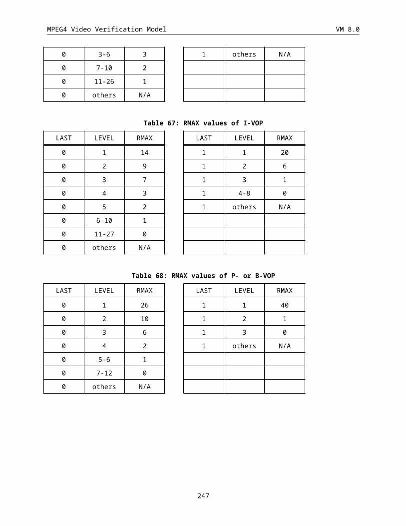
MPEG4 Video Verification Model VM 8.0
g i K gi N
si N
Ni N
f( ) ( ) cos(
( )), { , ,... };
2 1 2 2 10 1 1
Here f( , , )s is a triple consisting respectively of a positive scale, a modulation frequency, and a phase shift.
The constant K is chosen such that the resulting sequence is of unit norm. Now assume that a finite set of such
parameter triples is available. This would define a finite set of discrete 1-D functions, g i
( ), . Then the separable products of these 1-D functions forms a collection of 2-D discrete functions, as:
G i j g i g j i j N
, ( , ) ( ) ( ) , { , ,... }, , 0 1 1
The above notation assumes that all the 1-D functions have the same size N , but in practice each 1-D function may have its own associated size, N
. In this case the resulting 2-D basis functions may have an arbitrary rectangular extent. This idea is used in our basis set, which consists of all of the 2-D separable products of the 1-D discrete Gabor functions defined by the parameter triples shown in the following table.
247
Scale
( )sFreq
( )
Phase
( )f
Size (pixels)
( )N
1 0 0 1
3 0 0 5
5 0 0 9
7 0 0 11
9 0 0 15
12 0 0 21
14 0 0 23
17 0 0 29
20 0 0 35
1.4 1 /2 3
5 1 /2 9
12 1 /2 21
16 1 /2 27
20 1 /2 35
4 2 0 7
4 3 0 7
8 3 0 13
4 4 0 7
4 2 /4 7
4 4 /4 7
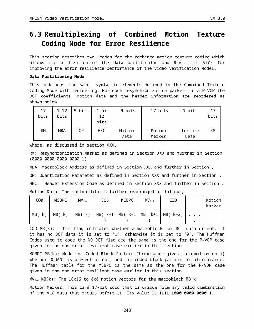
MPEG4 Video Verification Model VM 8.0
Parameter triples defining the 2-D Separable Gabor Basis Dictionary
Note that these parameter triples define 20 1-D Gabor functions and thus our dictionary consists of 400 different 2-D discrete Gabor basis shapes. Each of these shapes is windowed in both dimensions by N
, so the edges of most of the functions decay smoothly to zero. The first nine 1-D functions in the table represent Gaussians of increasing scale with no modulation; the remaining functions are modulated by a cosine function.
14.3.4.2 Finding Atoms
MP can be simply described as a multi-stage decomposition process. In theory, each basis function in the 2-D dictionary is compared to the residual image at all possible locations, and the basis shape and location which provide the best match are coded and subtracted from the residual image. The remaining residual energy is passed to the next stage, and the process is repeated. After m such basis functions are coded, the process stops, and the coded residual image consists of a weighted summation of m basis functions. At this point, parameters describing the basis shapes, locations and weighting values must be efficiently coded and transmitted to the receiver to allow the coded residual image to be reconstructed.
The decomposition is done differently in practice, since a full search using 2-D basis functions over the entire residual image would require a large amount of computing time. Instead of searching the entire image for the best match, a likely location is first identified using a procedure which is called “Find Energy” in the sequel. In this process, the residual image is partitioned into blocks and a sum-squared energy measure is computed for each block. The block with the largest energy measure is used for the center of a local inner product search which determines the shape and position of the coded atom. The remainder of this section describes the “Find Energy” and “Find Atom” procedures in more detail.
14.3.4.3 Detail Description of Find Energy
Find Energy is applied to each of the three color sub-images (Y,U,V), and the returned energy values are used to decide which of the sub-images will receive the next coded atom, and also what location within that sub-image will be the center for the local atom search. When the search is performed, each motion residual sub-image is partitioned into blocks and the sum-of-squares energy measure for each block is computed. A block-size of 1616 is used for the Y-sub-image, and a block-size of 88 is used for the U and V sub-images. A penalty weighting is applied to the energy measure computed for each block, based on the number of times the particular block has been awarded the local atom search during previous iterations. This reduces the likelihood of many atoms clustering in the same local region. After the penalty weights are applied, the maximum energy value and location are chosen for the sub-image: the value is the largest weighted sum-of-squares energy measure, and the location is the center of the block which produced the maximum value.
Once the maximum value and location are known for each of the three sub-images, the values are compared to decide which sub-image will receive the local atom search. This decision is made using a color weighting parameter, currently defined as CW = 4.0. The sub-image decision is made as follows:
If( (max_energy_Y > CW*max_energy_U) && (max_energy_Y > CW*max_energy_V) )
CODE A Y-ATOM AROUND LOCATION FOUND IN Y-SUBIMAGE
else if(max_energy_U > max_energy_V)
248
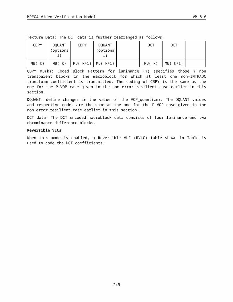
MPEG4 Video Verification Model VM 8.0
CODE A U-ATOM AROUND LOCATION FOUND IN U-SUBIMAGE
else
CODE A V-ATOM AROUND LOCATION FOUND IN V-SUBIMAGE
The local atom search procedure is the same regardless of which sub-image it is performed on. This procedure is described in the next subsection.
14.3.4.4 Detail Description of Find Atom
The search area for matching pursuit consists of a 1616 pixel area centered around the best energy location found in “Find Energy”. To perform the search, center each of the 2-D basis functions at each of the locations in the search area and compute the 2-D inner product between the basis function and the underlying image data. The largest inner product corresponds to the best match in a mean square error sense; thus the shape and location corresponding to the largest inner product are coded and transmitted. The value of the largest inner product becomes the expansion coefficient, which must be quantized and transmitted to the decoder. A fixed-stepsize linear quantizer with a quantization stepsize of 30 is used. Quantization is performed in the loop; that is, the expansion coefficient is quantized before the resulting basis function is subtracted from the remaining error signal. After this subtraction, the remaining energy in the error signal is passed to the next coding stage (i.e. the Find Energy and Find Atom procedures are repeated).
The issue of when to stop coding atoms is a rate control problem, and is discussed in corresponding section.
A global mean adjustment for luminance is also made, which can be seen as an additional basis function. This is effectively a flat basis function with the extent of the image to be coded. When the global mean adjustment is used, the mean value is quantized to 8 bits and transmitted according to the bitstream syntax description (see Syntax section).
14.3.4.5 Coding Atom Parameters
After the residual image is decomposed, the encoder is left with a list of the chosen atoms, which must be efficiently coded and transmitted to the receiver. Each atom is defined by five parameters which describe the position (x,y), basis shape (h,v), and the quantized expansion coefficient or modulus (m). Since all atoms are sent as a single combined layer, the subimage (Y, U, or V) to which each atom belongs must also be identified in the bitstream. Atoms are coded in position order, that is from left to right and top to bottom. For each atom in the stream, the position information is sent first, followed by the basis shape and then the modulus sign and value.
The position of each atom is coded differentially relative to the previous coded atom. Three fixed VLC tables are used. The first table (P1) is used at the beginning of a screen line to indicate the horizontal distance from the left side of the image to the location of the first atom on the line. For additional atoms on the same line, the second table (P2) is used to transmit the inter-atom distances. The P2 table also contains an escape code indicating that no additional atoms exist on the current line. This escape code, when used, is always followed by a code from the third table (P3), indicating how many lines in the image may be skipped before the next line containing coded atoms. The P3 code is always followed by a P1 code, since the next atom will be the first on a particular line. No special codeword is needed to indicate the end of the atom field, since the number of coded atoms is transmitted as header information.
249
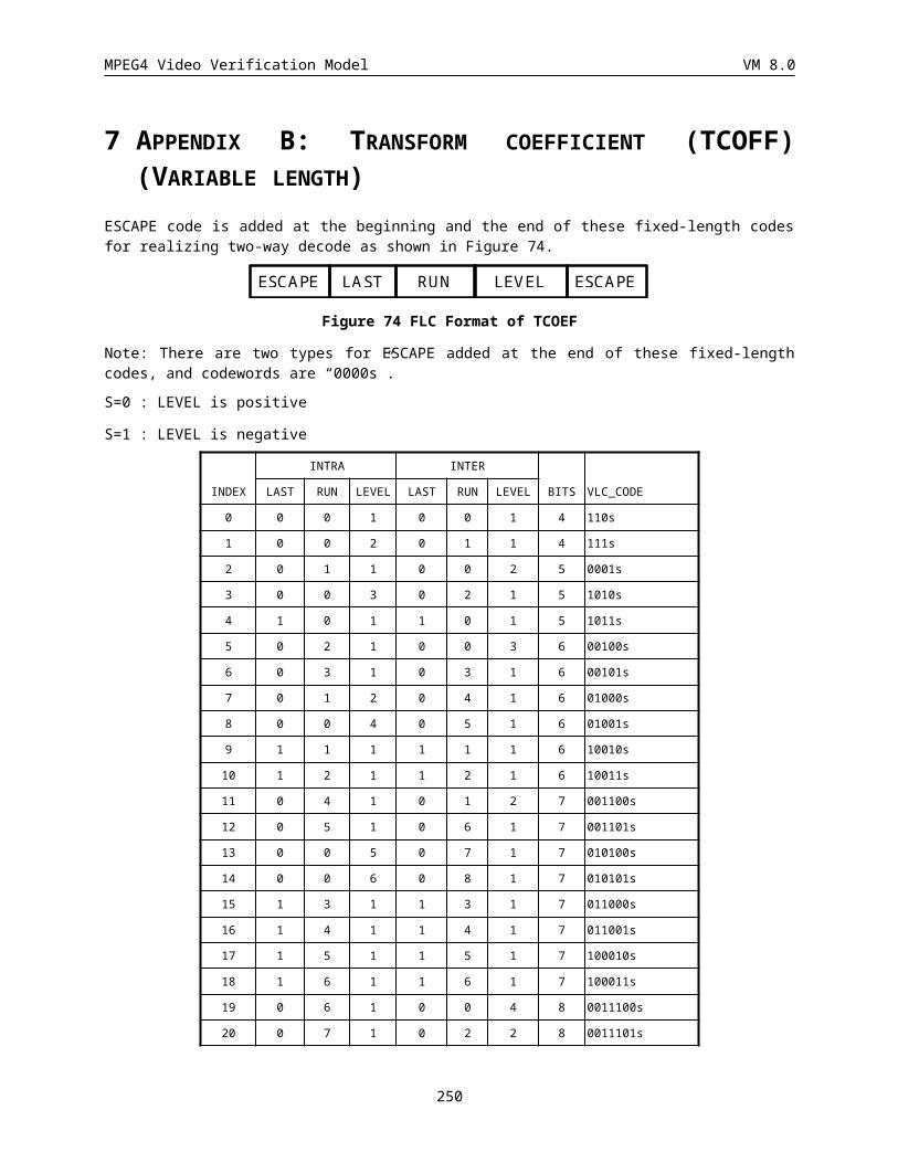
MPEG4 Video Verification Model VM 8.0
The basis shape (h,v) and modulus (m) are also represented using fixed VLC tables. Thus the horizontal and vertical shape tables have one entry for each of the twenty 1-D basis shapes, and the modulus table has one entry for each of thirty-two quantized values. Two additional escape codes are added to the horizontal basis shape table to indicate when an atom belongs to either the U or V sub-images; thus the horizontal shape table contains 22 codewords, while the vertical table contains only 20.
To illustrate atom coding, a Y-atom would be coded using the following syntax:
Codeword Comment
----------------------------------------------------------------------------------------------
POSITION Combination of P1,P2,P3 codes
HORZ_SHAPE Horizontal shape index
VERT_SHAPE Vertical shape index
QCOEF_SIGN 1-bit sign of quantized coefficient
QCOEF_VAL Value of quantized coefficient
To illustrate the chroma escape codes, a U-atom would be represented as:
Codeword Comment
----------------------------------------------------------------------------------------------
POSITION Combination of P1,P2,P3 codes
U-ESCAPE A special entry in the horizontal shape table
indicating that the current atom is a U-atom.
A second entry from horizontal shape table
is expected to follow.
HORZ_SHAPE Horizontal shape index
VERT_SHAPE Vertical shape index
QCOEF_SIGN 1-bit sign of quantized coefficient
QCOEF_VAL Value of quantized coefficient
Atoms from the V subimage are coded in the same way.
14.3.5 Rate Control
The MP coder achieves its target rate in the following manner. First it computes the prediction error bit budget by subtracting the bits used to code motion and header information from the total frame budget. It then computes a target number of atoms to code by dividing the prediction error budget by the average bit cost per atom in the previous frame. By coding this number of atoms, the overall target bit rate is approximately met. For the first frame MP encoder initializes the atom cost to 21.
250
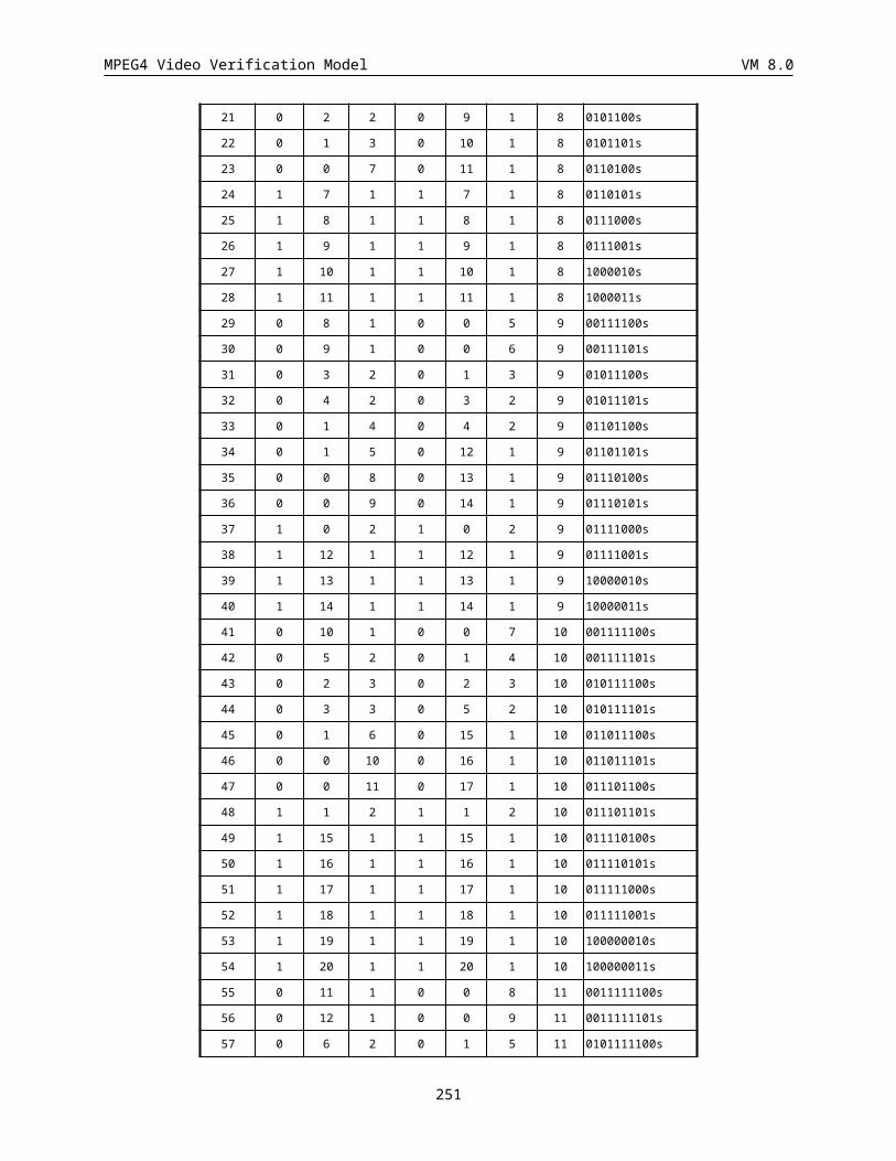
MPEG4 Video Verification Model VM 8.0
A constant-quality encoder can be achieved by setting up the MP coder to stop coding atoms when a certain quality metric is met. With either scheme, the matching pursuit coder does a good job of distributing the available bits to where they are needed, since atoms are essentially coded in decreasing order of importance.
14.3.6 Bitstream Syntax
Note: The vop_prediction_type table should be updated to include this mode.
14.3.6.1 VOL Syntax
MP mode supports separate mode, and does not support shape, scalability and error resilience so far.
14.3.6.2 Video Object Plane Class
In the MP mode, a modified version of the separate motion texture syntax is used.
The motion vectors for each macroblock are first sent as follows:
-----------------------------------------------------
MPMODE (MVD (MVD MVD MVD)) (DC DC DC DC DC DC)
-----------------------------------------------------
where MPMODE tells how the prediction for the macroblock is formed.
MPMODE Description
------ -----------
0 NOT_CODED (no additional fields for this macroblock)
10 INTER (a single motion vector follows)
110 INTER_4V (four motion vectors follow)
111 INTRA (six DC intra coefficients follow)
The motion vectors (MVD) are differentially coded as they are in the DCT-mode. For intra MBs, the DC INTRA coefficients for each sub-block are quantized to 5 bits and transmitted without prediction (Y_top_left Y_top_right Y_bottom_left Y_bottom_right U V). This is the only INTRA information sent together with motion. At the decoder, these average block values are used along with the overlapping motion window to form the prediction image, as described earlier
251
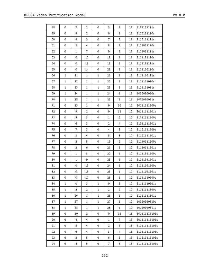
MPEG4 Video Verification Model VM 8.0
After the motion prediction information is sent for all macroblocks, the prediction error information is sent instead of the DCT data, using the following syntax:
---------------------------------------------
CODMEAN (MEAN) NUMATOMS VERT_SKIP (ATOM_DATA)
---------------------------------------------
CODMEAN (1-bit) Was the mean luminance basis function coded?
MEAN (8-bits) Global mean adjustment for luminance, if used.
NUMATOMS (10-bits) Number of atoms coded for this VOP.
VERT_SKIP (9-bits) Number of pixel lines to skip before first atom.
ATOM_DATA (variable) Parameters describing each atom in position order.
For each atom, the following data is sent in the ATOM_DATA field:
-----------------------------------------------------
POSITION HORZ_SHAPE VERT_SHAPE QCOEF_SIGN QCOEF_VALUE
-----------------------------------------------------
POSITION (vlc) Atom position
HORZ_SHAPE (vlc) Index into horizontal basis shape table
VERT_SHAPE (vlc) Index into vertical basis shape table
QCOEF_SIGN (1-bit) Sign of weighting coefficient
QCOEF_VAL (vlc) Quantized coefficient value
Escape codes within the horizontal basis shape table are used to indicate which subimage (Y, U, or V) the atom belongs to; this is described in Coding Atom Parameter section. Atom position coding is also described in the same section. Note that the first atom in a frame is coded slightly differently than the rest, since no previous atoms are available for differential position coding. The vertical position of the first atom is derived from the VERT_SKIP parameter sent in the atom field header. A codeword from the P1 position table is then sent to describe the horizontal position; the P1 prediction (normally equal to the most recently transmitted P1 code) is initially set to zero. The remaining atoms are coded differentially as described in Coding Atom Parameter section.
14.3.7 Matching pursuit VLC Tables
14.3.7.1 Modulus
252
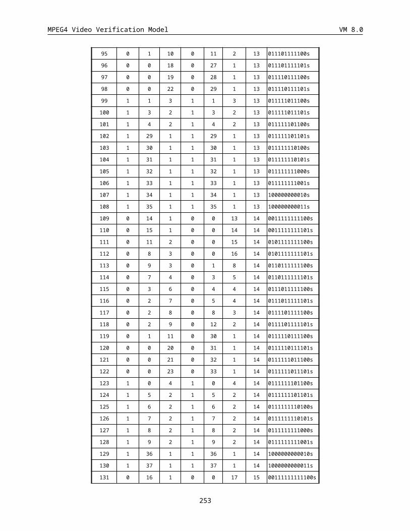
MPEG4 Video Verification Model VM 8.0
0 00
1 1
2 010
3 0110
4 01111
5 011101
6 01110000
7 01110010
8 011100010
9 011100111
10 0111000110
11 0111001100
12 01110001111
13 01110011011
14 011100110100
15 0111000111001
16 0111001101010
17 0111000111010
18 01110001110001
19 011100011101101
20 011100110101101
21 011100011100000
22 01110011010111
23 0111001101011001
24 011100011101110
25 011100011101111
26 0111000111000010
27 0111000111000011
28 011100110101100000
29 01110011010110001
30 011100110101100001
31 011100011101100
14.3.7.2 Basis
Horizontal Basis
0 001
1 1001
2 00010
3 11010
4 11111
5 111100
Vertical Basis 0 0100
1 0011
2 1001
3 00011
4 01011
5 010100
253
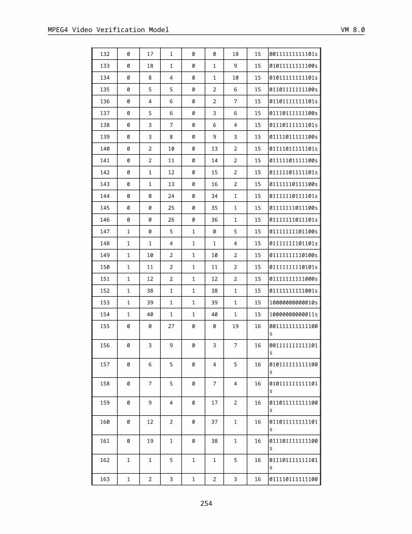
MPEG4 Video Verification Model VM 8.0
6 0100100
7 0100101
8 11011
9 0000
10 0101
11 10000
12 111101
13 010011
14 1100
15 1110
16 00011
17 0110
18 0111
19 101
20 01000
21 10001
6 010101
7 101101
8 00010
9 0111
10 110
11 1111
12 101100
13 10111
14 0110
15 1010
16 1000
17 1110
18 0010
19 0000
14.3.7.3 Position
P1 Table 0 00011100011001100
1 00011010110011000
2 00011100000100000
3 00011100000000100
4 00011010110011001
5 00011100001111100
6 00011010110011010
7 00011100000100001
8 00011100001010000
9 00011100001010010
10 00011010110011011
11 00011100001010011
12 00011100001101011
13 00010101110101110
14 00011010110101010
15 00011010110100011
16 00011010111110000
17 00011100000001101
18 00011010110101011
19 0001110000010001
235 1011011000
236 0110110000
237 1001011001
238 1011110011
239 0101000111
240 1001010100
241 0100011110
242 0011000111
243 0010110001
244 0001011111
245 0111111111
246 0011101001
247 1000011100
248 0011110111
249 0101000001
250 0001111110
251 0110011010
252 0110000010
253 0101011011
254 0010111100
470 1100001110
471 0101001111
472 0110010010
473 1001100010
474 0100011111
475 00001000110
476 0101011001
477 1011011111
478 00001111001
479 1001111000
480 1111000111
481 1111110011
482 1110000010
483 1110011010
484 1110000001
485 1100001111
486 00001000101
487 1111000101
488 1100101111
489 1010100111
254
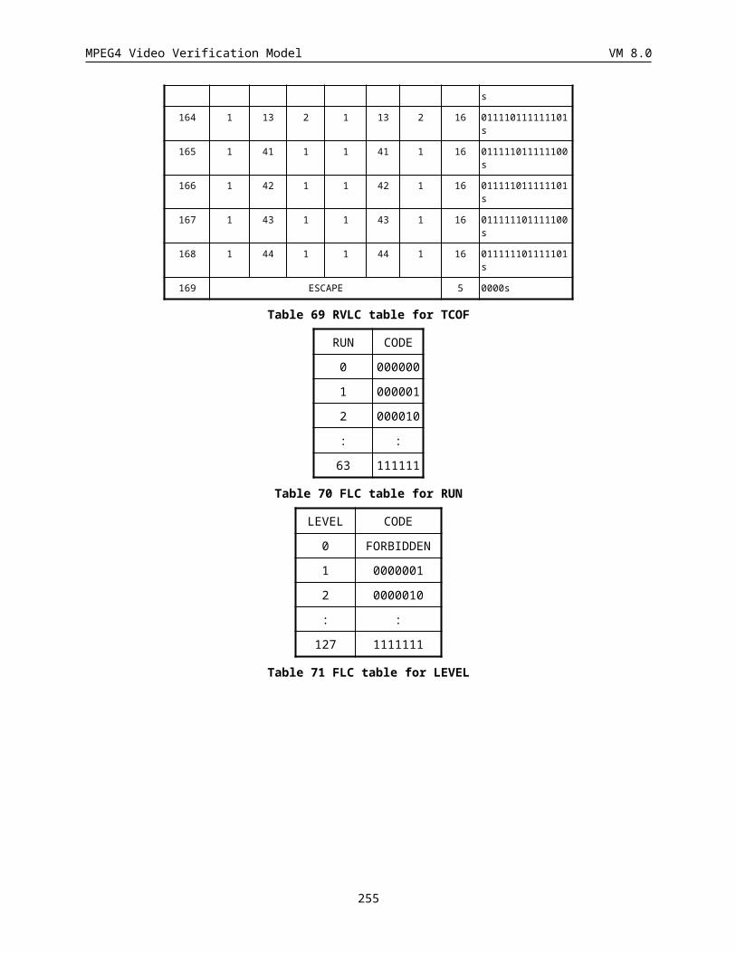
MPEG4 Video Verification Model VM 8.0
20 00000001011101010
21 00011010110100001
22 00011010110101100
23 00011010110100000
24 00011100000001100
25 0001110001100111
26 00010101110100111
27 00011010111110001
28 00011010110101101
29 00011100011001101
30 00011010101010100
31 00011010111110010
32 00011010101010101
33 011001010011111
34 00000001011101011
35 0001110000000111
36 00011010101010110
37 00011010111110011
38 0001110001001111
39 0001101010111110
40 00011010101010111
41 0110010110000101
42 000101011101010
43 0010100001101000
44 0001101011000011
45 00011100000000110
46 00011010111110110
47 011001010011110
48 0000000101110111
49 011001011010100
50 0001101011010100
51 000110101101001
52 0001101010111111
53 00011100000000111
54 11000000111011
55 01100101001000
56 01100101101000
57 0001110000101100
58 01100101011010
59 000111000010111
60 10111111111101
61 00010101110100110
62 11001011100001
255 0001011101
256 0000001101
257 0010000101
258 0000110000
259 0001111100
260 0010110000
261 0001011110
262 0000000100
263 111111000
264 110000110
265 0000101110
266 0001010110
267 0011100011
268 111110000
269 101111011
270 111111100
271 111001111
272 111001010
273 100101011
274 110010100
275 100001010
276 011011011
277 100111101
278 110000000
279 011010100
280 010110101
281 101100101
282 100001001
283 100111110
284 100111000
285 011111001
286 100111111
287 010010001
288 001100010
289 100101101
290 011001000
291 001111101
292 010010101
293 010101001
294 010001100
295 010101000
296 010010000
297 010101011
490 1011110010
491 00000011000
492 00000110101
493 1110000011
494 00001000111
495 1001110011
496 00001111011
497 00010100101
498 00111110011
499 00011100110
500 10000111010
501 00001000100
502 00111001000
503 1111101010
504 01000110111
505 1101000111
506 01100000011
507 01101100011
508 10011000000
509 01100000010
510 01001001001
511 10110110011
512 11111110101
513 11100110000
514 10000111011
515 01011011011
516 001110010110
517 01010011010
518 10110010011
519 10011000001
520 10110110010
521 00111110010
522 10101100101
523 001010000111
524 01101100010
525 11111110100
526 11111010010
527 11010011011
528 000001101101
529 11100110010
530 11000000100
531 10011100100
532 01111111001
255
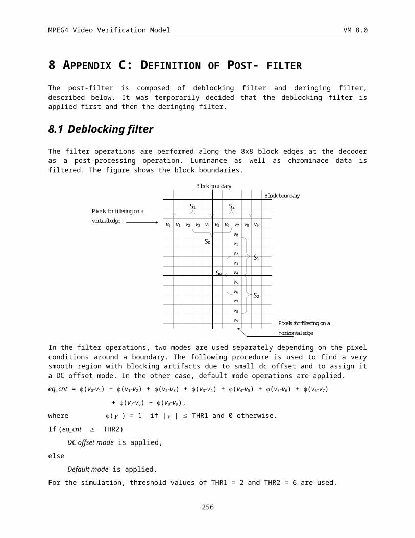
MPEG4 Video Verification Model VM 8.0
63 000101011101000
64 011001010010010
65 000111000001001
66 10111111110010
67 01100101001110
68 000111000101100
69 00011100000000000
70 01100101101011
71 0001101011111010
72 00011100001100
73 000110101100100
74 011001011101000
75 000111000101101
76 011001011010101
77 011001010010110
78 01000001110100
79 11001010100110
80 01100101001010
81 01100101101001
82 10111111111100
83 011001011000011
84 000111000110010
85 00011010111110111
86 00000001011100
87 011001010001010
88 00011010101110
89 01100101011110
90 000111000011101
91 11001010100111
92 000110101010100
93 01100101000100
94 1001011111111
95 11001010100100
96 00011100011111
97 01000001011010
98 01100101110110
99 1011111111000
100 0110010100011
101 00011100000000001
102 000111000000010
103 01000001010111
104 000111000010000
105 0110010101110
298 001111010
299 001110111
300 010101010
301 001110110
302 001010010
303 001000011
304 010010111
305 001110000
306 000101010
307 000110100
308 001000110
309 11110000
310 000010000
311 000000111
312 000111100
313 11100001
314 000000011
315 11010010
316 10110011
317 11000001
318 11100100
319 10011011
320 11000010
321 01111110
322 10000110
323 10011001
324 01101011
325 01100111
326 01010111
327 01000000
328 00111100
329 00011101
330 00100000
331 00001110
332 00011011
333 00001101
334 00000111
335 00001001
336 1100010
337 1100100
338 0110111
339 0110100
340 0100001
533 000011000110
534 11010011000
535 000011000111
536 11110001101
537 001110100010
538 010110110100
539 010001101101
540 11100000001
541 11111010011
542 00101011100
543 101101111011
544 011111110100
545 101111111101
546 000001101000
547 001110100001
548 0000101111101
549 011111110001
550 111000000001
551 100101111101
552 0101001100011
553 011001011100
554 010000011100
555 0011100101001
556 101100100010
557 011111110101
558 011111110000
559 1001111001001
560 100101010111
561 111000000000
562 0010001110000
563 0000001100101
564 0100000101100
565 111100011001
566 110010101000
567 110100110100
568 0001101011101
569 0001010111011
570 101010100001
571 0000011010011
572 0100011011001
573 01000001011011
574 0010111110000
575 100101111110
256
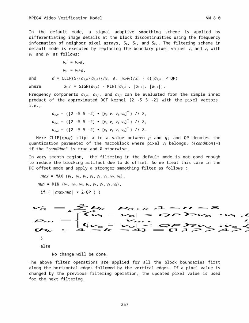
MPEG4 Video Verification Model VM 8.0
106 0011101000111
107 0110010111100
108 00011100010010
109 0100000111011
110 0110010100001
111 0110010111111
112 0110010110110
113 0001110000011
114 0010111110001
115 0001110001110
116 0001101010110
117 1100000010110
118 1001010101100
119 0100000101111
120 0010100001100
121 0100000101110
122 1100101110001
123 0101001100101
124 0000000101101
125 0110010100110
126 111001100010
127 0001110001000
128 1100000011111
129 0000011010010
130 0001110000001
131 1100000010100
132 010110001111
133 1100000010101
134 101111010101
135 101100100001
136 0100000101010
137 1001111001000
138 0000000101100
139 100101111100
140 0010001110001
141 0001101011100
142 111100011000
143 101111010100
144 010110110101
145 0001101011011
146 0010111110010
147 0000000101111
148 101010100000
341 0010101
342 0000010
343 110101
344 101110
345 100000
346 010111
347 001001
348 000100
349 11011
350 01110
351 10100
352 10001
353 11101
354 001101
355 010011
356 011110
357 100100
358 110011
359 111101
360 0001100
361 0011001
362 0100010
363 0110001
364 1011000
365 1011010
366 1100011
367 00000010
368 1110001
369 00000000
370 1111001
371 00010110
372 00110000
373 00101110
374 00101101
375 00111111
376 01010010
377 01100001
378 01111101
379 10010100
380 10011010
381 10011101
382 10101000
383 10111110
576 0011100101000
577 101101111010
578 1100000010111
579 0001101011110
580 0001110001101
581 0110010100000
582 0101001100110
583 0000001100100
584 0001101010100
585 110010111001
586 0110010101100
587 0010111110011
588 1001111001011
589 1001010101101
590 0101001100010
591 1001011111110
592 0100011011000
593 0101001100111
594 0011101000110
595 00011100011110
596 11000000111101
597 0101001100100
598 011001011111011
599 11001010100101
600 00011100011000
601 1110011011010
602 00011100000101
603 10111111111011
604 000111000010101
605 00011100001001
606 000111000010001
607 1110011001101
608 011001010110110
609 01100101100011
610 1100000011100
611 011001010110111
612 01100101101111
613 00101000011011
614 11001011100000
615 01000001110101
616 011001011101001
617 01000001010110
618 1001111001010
257
MPEG4 Video Verification Model VM 8.0
149 010100110000
150 111001101100
151 111001100111
152 101100100011
153 111001100011
154 0000101111100
155 0001110001010
156 010110001110
157 110100110101
158 011001011001
159 101100100000
160 001000111001
161 11001010101
162 10011110011
163 000000010100
164 001110010101
165 010000010100
166 001110010111
167 000000010101
168 000010111111
169 10101010001
170 000000110011
171 10011100101
172 11001011101
173 10111101011
174 10011000110
175 11000000110
176 11100110111
177 00011010100
178 10101100100
179 10110111100
180 001110100000
181 01010011011
182 01111100011
183 000001101100
184 10010101010
185 01010001101
186 01000001111
187 11010011001
188 01111111011
189 10011000111
190 01010011101
191 01011000110
384 11010000
385 11111001
386 10101111
387 000011111
388 000111101
389 000010110
390 11111101
391 000011001
392 001000101
393 000101000
394 11111011
395 000010101
396 001110101
397 001000100
398 000010100
399 001010011
400 001110011
401 001010001
402 010110000
403 010010100
404 010010110
405 001011001
406 100001011
407 011011001
408 010001110
409 100001111
410 010010011
411 010100010
412 011011010
413 010100001
414 010110111
415 011001100
416 100001000
417 010110010
418 101010110
419 011010101
420 101011011
421 100101110
422 101011010
423 010110011
424 101111000
425 101011000
426 101010101
619 01100101111011
620 000110101010110
621 011001011011100
622 01100101011111
623 00011010110100010
624 01100101110111
625 000110101100111
626 01100101111010
627 011001011011101
628 0001101011010111
629 10111111111010
630 00011010111111
631 011001010010111
632 011001010010011
633 1110011001100
634 011001011111010
635 000110101100011
636 01100101110101
637 000111000101110
638 11000000111100
639 10111111110011
640 11000000111010
641 000110101010111
642 10111111111111
643 011001011000000
644 10111111111000
645 011001011111001
646 1110011011011
647 10111111111110
648 01100101100010
649 10111111111001
650 000110101100000
651 0001101011001010
652 011001011000001
653 000111000011011
654 0001010111010110
655 011001011111000
656 00000001011101001
657 011001010001011
658 0001010111010010
659 0001110001001101
660 000111000011100
661 00011100001101010
258
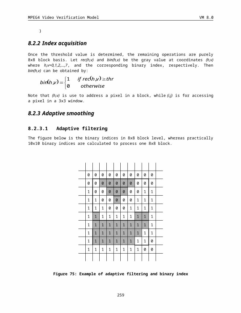
MPEG4 Video Verification Model VM 8.0
192 10110010010
193 01010001100
194 01001001000
195 01111100010
196 01100101010
197 00010100100
198 01010011100
199 00111001001
200 00100011101
201 00000110111
202 00011111111
203 00001111010
204 00001111000
205 1100101100
206 00101111101
207 1111111011
208 00101000010
209 00001100010
210 1111000100
211 00001011110
212 1100101011
213 1111101000
214 00010101111
215 00011100111
216 1101000110
217 1111101011
218 1100101101
219 00011111110
220 1101000100
221 1011111101
222 0110000011
223 1111110010
224 1011110100
225 1010111010
226 1011111100
227 1011111110
228 0110011011
229 1010100110
230 1001100001
231 0110000000
232 1001011000
233 1101000101
234 0111110000
427 101010111
428 101101101
429 101101110
430 111001110
431 101011100
432 101010010
433 110100111
434 0010001111
435 111110001
436 0011000110
437 0000011000
438 0010000100
439 0011110110
440 0101000000
441 0001011100
442 111111111
443 0001010011
444 111001011
445 0001110010
446 0011111000
447 111111110
448 0100000110
449 0111111110
450 0100000100
451 0010111111
452 0100100101
453 0010100000
454 0101011010
455 0011100010
456 0110010011
457 0010111101
458 0101101100
459 0000011001
460 0100011010
461 0001111101
462 1001011110
463 0101100010
464 1010110011
465 0101101000
466 0101101001
467 1010111011
468 0101011000
469 1010101001
662 0001101011000010
663 00011100000000101
664 0001110000111100
665 00011100001111101
666 00011100001111110
667 00011100001111111
668 0001101010111101
669 00011100001010001
670 0001110000000001
671 0110010110000100
672 00101000011010100
673 00101000011010101
674 0001110001001100
675 00010101110101111
676 00011100001101000
677 00011100001101001
678 00101000011010010
679 00101000011010011
680 00011010110010110
681 00011010110010111
682 00000001011101100
683 00000001011101101
684 00101000011010110
685 00101000011010111
686 00011100001111010
687 00011100001111011
688 00011100010011100
689 00011100010011101
690 00011100001011010
691 00011100001011011
692 00011010110001010
693 00011010110001011
694 00011010101111000
695 00011010101111001
696 00011100010111110
697 00011100010111111
698 00011100010111100
699 00011100010111101
700 00011010110001000
701 00011010110001001
702 00000001011101000
259
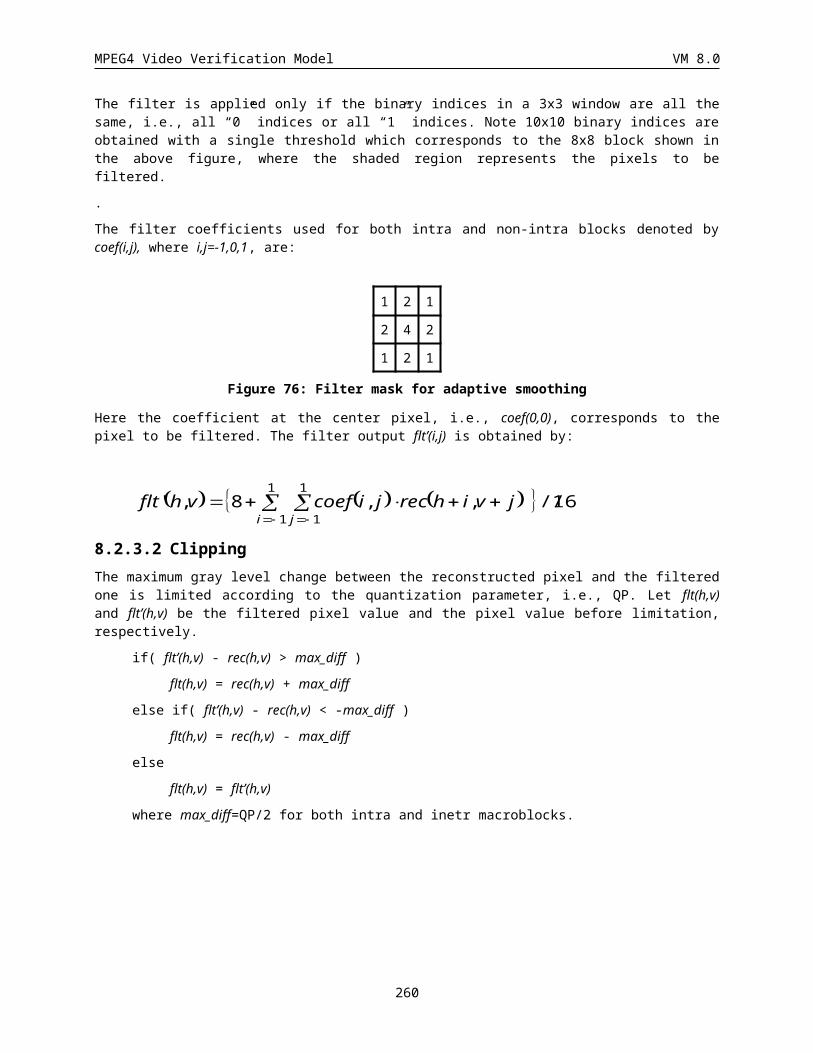
MPEG4 Video Verification Model VM 8.0
P2-Position
0 01010
1 00001
2 00101
3 01011
4 01110
5 000100
6 000111
7 001110
8 010001
9 011001
10 011111
11 0001011
12 0010000
13 0011110
14 0011010
15 0100101
16 0100111
17 0111100
18 0110111
19 00000100
20 00000101
21 00000111
22 00010101
23 00100100
24 00100111
25 00110110
26 00110001
27 01000000
28 01000010
29 01001100
30 01100001
31 01101001
32 01111011
33 01101100
34 000000011
35 000000010
36 000000101
37 000000110
38 000000100
39 000110000
118 01001001001
119 00110111001
120 00110111000
121 00110000111
122 00110000100
123 00110000110
124 00100010100
125 00011010011
126 00011001011
127 00110010010
128 00111110001
129 01000001010
130 01100010001
131 01001000001
132 01101010011
133 01001101011
134 01111010001
135 000000000101
136 01001101010
137 000000000110
138 000000000100
139 01101101001
140 01100010111
141 01101000001
142 01101011010
143 001000101101
144 000101001010
145 000001101001
146 001001011111
147 001000101100
148 01101011011
149 001101110100
150 001101110101
151 001100000001
152 001001010010
153 001100000000
154 011000100000
155 001001010001
156 010010000001
157 000110100011
236 01000001011000
237 01001001000101
238 000000111100010
239 01101010010000
240 00111110000101
241 01111010000010
242 001100100000110
243 000110100100100
244 01111010000000
245 01111010000111
246 011110100000011
247 011011010001100
248 010000010110011
249 011011010001101
250 010010010001001
251 01001000000011
252 0100110100000111
253 000001101000001
254 0100110100000010
255 0000001111010110
256 000001101000000
257 011011010001111
258 0001101001000010
259 0100110100000000
260 0100110100000101
261 00100101000010000
262 0100110100000011
263 000110100010001100
264 0001101001000001
265 000110100100000010
266 010010010001101
267 00011010001000000
268 00011010001000011
269 010011010000111
270 0100100100010001
271 00011010010011001
272 000110100100111001
273 00011010010000110
274 00011010010011110
275 0100110100000110
260
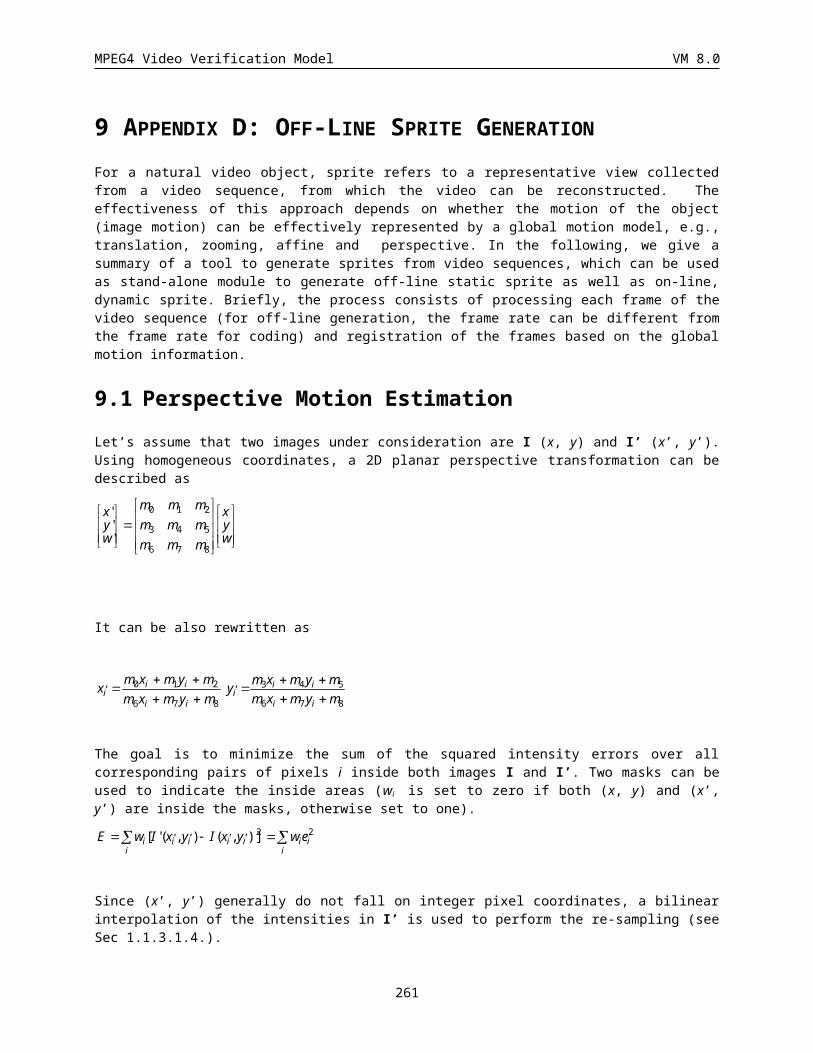
MPEG4 Video Verification Model VM 8.0
40 000101000
41 000110001
42 000110110
43 001000100
44 000110111
45 000110101
46 001001100
47 001111101
48 000110011
49 001000111
50 001100110
51 001100101
52 001100111
53 010000011
54 001111110
55 001111111
56 010011011
57 011010001
58 011000000
59 010010001
60 010000111
61 011110101
62 010010011
63 0000000010
64 011000001
65 011010101
66 011011011
67 0000000000
68 0001010011
69 0010001100
70 0000011001
71 0010010101
72 0000011000
73 0011011111
74 0010011010
75 0010010110
76 0001100100
77 0010001101
78 0100000100
79 0011111001
80 0011011110
81 0110001110
82 0100100101
158 010011010011
159 001111100000
160 001001010011
161 011000100001
162 011010100101
163 011000110101
164 011010000001
165 010010010000
166 0000000001111
167 0000011010001
168 011010000000
169 011000110110
170 011000110100
171 011000110111
172 010011010001
173 010011010010
174 0001010010110
175 0001100101011
176 011000101100
177 0011001001111
178 0100000101110
179 0000001111001
180 0100000101111
181 0000001111011
182 0010010100000
183 0001100101001
184 0001100101010
185 0011001000011
186 0010010111101
187 0011001001101
188 0110110100010
189 0011001001110
190 0110110100001
191 0011001000000
192 00000011110100
193 00010100101110
194 00000011110000
195 0110001011011
196 00011001010000
197 0110001011010
198 0111101000010
199 01001000000010
200 01111010000110
276 0100100100010000
277 0000000001110000
278 000110100010000011
279 0001101001000101
280 000110100010001101
281 0100100100011110
282 00000000011100010
283 001100100000111
284 00011010010001110
285 000110100100000011
286 000110100010000010
287 0100100100011111
288 00000000011100011
289 0001101001000100
290 0100110100001100
291 010010010001110
292 00011010010111100
293 00011010010001101
294 00011010010011101
295 011110100000010
296 0001101000100010
297 0001101001001101
298 01001101000000011
299 0000001111010111
300 01001101000000010
301 0100110100000100
302 011011010001110
303 00011010010010100
304 00011010010110100
305 000110100100011111
306 00011010010110111
307 00011010010110000
308 000110100100101010
309 0100110100001101
310 000110100100011110
311 00011010010011111
312 000110100100011001
313 000110100100011000
314 001001010000100011
315 000110100101100011
316 000110100100111000
317 000110100101100010
318 000110100100110001
261
MPEG4 Video Verification Model VM 8.0
83 0100001100
84 0110001010
85 0110100001
86 0110001001
87 0111101001
88 0110001111
89 0110101111
90 0100001101
91 0110101100
92 0110001100
93 00000011100
94 0100100001
95 00000000111
96 0110101110
97 0110101000
98 00000000110
99 0110110101
100 00000110111
101 00000011111
102 00000110110
103 00010100100
104 00110000101
105 00100110111
106 00011010000
107 00110000011
108 00000110101
109 00000011101
110 00100110110
111 00110010001
112 00110000010
113 00110000001
114 00110111011
115 00100101110
116 00100010111
117 00100010101
201 00110010000100
202 0100100000000
203 00011010001011
204 0100000101101
205 0110101001001
206 00000000011101
207 00100101111001
208 01111010000011
209 010000010110010
210 00011010001001
211 00110010000010
212 00000110100001
213 000000000111001
214 00010100101111
215 00111110000111
216 00110010011000
217 0110110100000
218 01101010010001
219 001001010000101
220 00110010000101
221 00011010001010
222 00011010010101
223 000000111100011
224 000000111101010
225 010010010001100
226 00111110000100
227 00100101000011
228 000110100101110
229 010011010000101
230 00100101111000
231 010011010000100
232 00111110000110
233 00110010011001
234 00011001010001
235 00011010010100
319 000110100100101011
320 001001010000100010
321 000110100100110000
322 000110100101101100
323 000110100101101101
324 000110100101111010
325 000110100101111011
326 000110100101101010
327 000110100101101011
328 000110100101111100
329 000110100101111101
330 000110100100101100
331 000110100100101101
332 000110100100101110
333 000110100100101111
334 001001010000100110
335 001001010000100111
336 000110100010000100
337 000110100010000101
338 000110100101100100
339 000110100101100101
340 000110100101100110
341 000110100101100111
342 001001010000100100
343 001001010000100101
344 000110100010001110
345 000110100010001111
346 000110100100000000
347 000110100100000001
348 000110100100001110
349 000110100100001111
350 000110100101111110
351 000110100101111111
352 1
P3-Position
0 1001010110101101
1 0
2 11
3 101
96 1001011000011111
97 1001011001011001
98 1001011001011100
99 1001011010100001
190 1001011010010111
191 1001011001100110
192 1001011001100111
193 1001011011000100
262
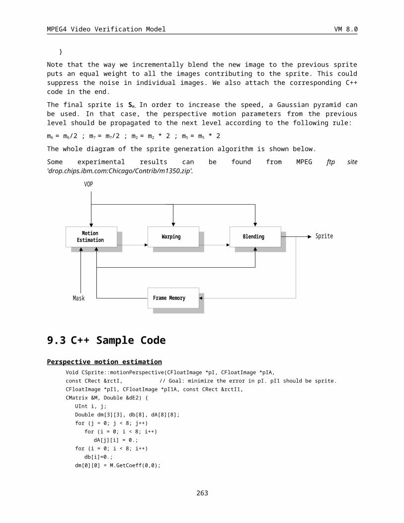
MPEG4 Video Verification Model VM 8.0
4 10000
5 10011
6 100011
7 1000101
8 1001001
9 10001000
10 10010001
11 100010011
12 100010010
13 100101000
14 100101010
15 100101110
16 1001000001
17 1001000011
18 1001010010
19 10010000000
20 1001011110
21 10010000100
22 10010000101
23 10010101110
24 10010100111
25 100101011011
26 100101001101
27 10010111111
28 100101011001
29 10010111110
30 100101011000
31 100101101111
32 1001000000111
33 1001010011000
34 1001011011011
35 100101101110
36 1001000000110
37 10010100110011
38 1001011010011
39 1001011011010
40 1001000000101
41 10010101101000
42 100101101010101
43 1001011010000101
44 100101101000110
45 100101100001101
46 10010100110010
100 1001010111101101
101 1001011010100000
102 1001011000010111
103 1001011000001100
104 1001011001100011
105 1001011001100001
106 1001011000111010
107 1001011001100010
108 1001011000111111
109 1001011000111110
110 1001011000001101
111 1001011001110011
112 1001011000110100
113 1001011000110010
114 1001011000111000
115 1001011000110011
116 1001011011001000
117 1001000000100011
118 1001010110100100
119 1001011000011000
120 1001010111110001
121 1001011000110101
122 1001011000011110
123 1001010111110000
124 1001011000010000
125 1001011000011001
126 1001010110100101
127 1001010111101110
128 1001011001010010
129 1001010111110010
130 1001011001110010
131 1001010111110011
132 1001010111101100
133 1001011011001001
134 1001011011001110
135 1001011000010001
136 1001011010101101
137 1001011001010011
138 1001011001100000
139 1001011010101100
140 1001011000010011
141 1001011000010010
142 1001011001011101
194 1001011011000101
195 1001011000101100
196 1001011000101101
197 1001011001010100
198 1001011001010101
199 1001011001110110
200 1001011001110111
201 1001011010100010
202 1001011010100011
203 1001010111111000
204 1001010111111001
205 1001011010001000
206 1001011010001001
207 1001011011001010
208 1001011011001011
209 1001011000000100
210 1001011000000101
211 1001011010100110
212 1001011010100111
213 1001011010100100
214 1001011010100101
215 1001011000010100
216 1001011000010101
217 1001011001011110
218 1001011001011111
219 1001011000110000
220 1001011000110001
221 1001011001110000
222 1001011001110001
223 1001011000110110
224 1001011000110111
225 1001010111111110
226 1001010111111111
227 1001010111100100
228 1001010111100101
229 1001011000001110
230 1001011000001111
231 1001010111100110
232 1001010111100111
233 1001011000011100
234 1001011000011101
235 1001010111110100
236 1001010111110101
263
MPEG4 Video Verification Model VM 8.0
47 100100000010011
48 10010110101110
49 1001011010000110
50 100100000010010
51 1001010110101111
52 1001011001100100
53 1001010110101110
54 1001011010000100
55 1001010110101100
56 1001011011000011
57 1001011001100101
58 1001011000111011
59 1001010111111011
60 1001011011000000
61 1001010111111010
62 1001000000100010
63 1001011011000010
64 1001011000100011
65 1001011011000001
66 1001011011001101
67 1001011001000001
68 1001011010010010
69 1001011001000000
70 1001010111101111
71 1001011000100010
72 1001011001111101
73 1001011010010011
74 1001011000111001
75 1001011010010001
76 1001011010000010
77 1001011010010000
78 1001011000010110
79 1001011001111100
80 1001010111101001
81 1001011010000011
82 1001010111110111
83 1001010111101011
84 1001011000000000
85 1001010111101010
86 1001011010000111
87 1001010111101000
88 1001011001011011
89 1001011000000001
143 1001011011001100
144 10010000001000010
145 1001011001110100
146 1001011001110101
147 1001011000100100
148 1001011000100101
149 1001011000100110
150 1001011000100111
151 1001011001001110
152 1001011001001111
153 1001011000101000
154 1001011000101001
155 1001011010110100
156 1001011010110101
157 1001011010110110
158 1001011010110111
159 1001011001111000
160 1001011001111001
161 1001011000100000
162 1001011000100001
163 1001011001000010
164 1001011001000011
165 1001011001101000
166 1001011001101001
167 1001011010010100
168 1001011010010101
169 1001011001111110
170 1001011001111111
171 10010000001000000
172 10010000001000001
173 1001011001111010
174 1001011001111011
175 1001011010111110
176 1001011010111111
177 1001011010000000
178 1001011010000001
179 1001010111100000
180 1001010111100001
181 1001010110101000
182 1001010110101001
183 1001011001101100
184 1001011001101101
185 1001011000000010
237 1001011000111100
238 1001011000111101
239 1001010110101010
240 1001010110101011
241 1001011010111100
242 1001011010111101
243 1001011001010000
244 1001011001010001
245 1001010111111100
246 1001010111111101
247 1001011001001000
248 1001011001001001
249 1001011010001110
250 1001011010001111
251 1001011010101000
252 1001011010101001
253 1001011000001000
254 1001011000001001
255 1001011010001010
256 1001011010001011
257 1001011001010110
258 1001011001010111
259 1001011010101110
260 1001011010101111
261 1001010110100110
262 1001010110100111
263 1001010111100010
264 1001010111100011
265 1001011001101110
266 1001011001101111
267 1001011001000110
268 1001011001000111
269 1001011001101010
270 1001011001101011
271 1001011000101110
272 1001011000101111
273 1001011001001010
274 1001011001001011
275 1001011001000100
276 1001011001000101
277 1001011000001010
278 1001011000001011
279 1001011010110000
264
MPEG4 Video Verification Model VM 8.0
90 1001011011001111
91 1001011011000111
92 1001011001011000
93 1001011011000110
94 1001010111110110
95 1001011001011010
186 1001011000000011
187 1001011001001100
188 1001011001001101
189 1001011010010110
280 1001011010110001
281 1001011000000110
282 1001011000000111
283 1001011010110010
284 1001011010110011
285 1001011000101010
286 1001011000101011
287 10010000001000011
14.4 Arbitrary shaped spatial scalabilityVM 8 supports both temporal and spatial scalability in the combined syntax, which is referred to as generalized scalability. Since VOPs can have a rectangular shape or an arbitrary shape, both the traditional frame based and the object based scalability should be available. The extension to the object based scalability is described in this appendix.
14.4.1 Semantics for Object Based ScalabilityAt this moment, this extension is based on the same syntax in VM8. The encoding and decoding process is the same as the case for the rectangular shaped scalability, which is described in VM8. However, it will be possible to reduce the overhead with additional syntax change. The following semantics modifications are necessary for the extension to the object based scalability.
1. Padding and upsampling process
2. The size and the locations for the reference and the current VOP.
3. background_composition
14.4.2 Padding and upsampling process If the reference VOP in the base layer has rectangular shape, the reference VOP is up - sampled. If the reference layer refereed has arbitrary shape, padding should be done before the up-sampling process. Otherwise, the boundary will be degraded.
14.4.3 Location of VOPIn the case of arbitrary shape VOPs, its size and locations change from time to time. In order to ensure the operation of motion compensation and the prediction from the base layer, it is necessary to identify the location of the VOPs in the absolute coordinate system.
First of all, the location of the reference VOPs should be identified.
265
MPEG4 Video Verification Model VM 8.0
14.4.3.1 With up-sampling processThis is the case that hor_sampling_factor_n/hor_sampling_factor_m or vert_sampling_factor_n/vert_sampling_factor_m is not equal to 1. In this case, the upsampled base layer is used as the reference VOP. If the base layer is rectangular in shape, the spatial reference of the
upsampled VOP is set to (0,0). If the base layer is an arbitrary shape, VOP_horizontal_mc_spatial_ref and VOP_vertical_mc_spatial_ref in base layer is scaled by*_sampling_factor_n/*_sampling_factor_m.
14.4.3.2 Without up-sampling processThis is the case that hor_sampling_factor_n/hor_sampling_factor_m and vert_sampling_factor_n/vert_sampling_factor_m is equal to 1. In this case, up - sampling is not done. If the reference layer has rectangular shape, the spatial reference of the reference VOP is set to (0,0). If the reference layer has arbitrary shape, the locations are encoded as VOP_horizontal_mc_spatial_ref and VOP_vertical_mc_spatial_ref in the reference layer.
14.4.4 Background composition background_composition is encoded when enhancement_type is set to ‘1’. The definition of the background composition is extend to the spatial scalability. In addition to the current definition, the following definition is included. If background_composition is set to 1, the output image from the enhancement layer decoder should be placed on the upsampled decoded image of reference layer. In the case of spatial scalability, load_backward_shape and load_forward_shape is always set to ‘0’.
14.5 Multiple Video Object Rate Control
This section describes an algorithm which achieves a constant bit rate when coding multiple video objects. This implementation is based on the quadratic rate-distortion model presented in [MPEG95/0436]. For I-frame and first P-frame coding, macroblock-based quantization parameters are determined according to an algorithm based on human visual sensitivity (HVS) [MPEG97/0566]. For the remaining P-frames, the framework as proposed in [MPEG97/2219,2554] is used. For this scheme, each object maintains its own set of parameters. With these parameters an initial target estimate is made for each object. Based on the buffer fullness, the total target is adjusted and then distributed proportional to the size of the object, the motion which the object is experiencing, and its MAD. Based on the new individual targets and second order model parameters, appropriate quantization parameters can be calculated for each video object. To compromise the tradeoffs in spatial and temporal coding, two modes of operation have been introduced. With these modes, suitable decisions can be made to differentiate between low and high bit rate coding. In addition, a shape rate control algorithm has been included.
This scheme assumes that the encoder rate-distortion function for the ith VO is modeled as:
R[i]=X1[i]*S[i]*Q[i]**(-1)+X2[i]*S[i]*Q[i]**(-2)
The notation above is consistent with the model for SVOP described in 3.7.1. However, all variables have been extended to vector quantities to reflect the information in each VO.
The algorithm for performing the joint rate control can be decomposed into a pre-encoding stage and a post-encoding stage. As shown in Fig. 1, the pre-encoding stage consists of: i) the target bit estimation, ii) joint buffer
266
MPEG4 Video Verification Model VM 8.0
control, iii) pre-frameskip control and iv) the quantization level and alpha threshold calculation; whereas the post-encoding stage consists of: i) updating the rate-distortion model, ii) post-frameskip control, and iii) determine mode of operation.
14.5.1 Initialization
The initialization process is very similar to the SVOP initialization process. Since a single buffer is used, the buffer drain rate and initializations remains the same, but many of the parameters are extended to vector quantities. A new feature of this block is the automatic selection of quantization parameters for the I-frame coding. This techniques to accomplish this are covered in the next section. This technique applies to multiple-VO rate control, single-VO rate control, and MB rate control.
14.5.2 Quantization level calculation for I-frame and first P-frame
To calculate the quantization parameters which are used for the I-frame and first P-frame, a bit allocation table based on Human Visual Sensitivity (HVS) of color tolerance is used. This scheme assigns a target bit rate which is predicted by histogram of variance and HVS classification.
Color/Variance classification: A macro block is classified into one of 32 macro block classes based on HVS and one of 16 classes based on the variance. A reference quantization step size is assigned to the macro block according to its macro block class. A macro block is classified into a sensitive category if the number of pixels in the macro block which satisfy LUT is larger than a threshold value. Otherwise the macro block is classified into insensitive category.
texture class H Vn n_
H P P thn x y x yxy
, ,1
1
16
1
16
V P P thn x y x yxy
, , 1
1
16
1
16
th f Px yxy
,
1
16
1
16
color class color tolerance_ min _
color tolerance LUT colormean_
color Pmean x yxy
1
64 1
16
1
16
,
The block variance classification allows us to estimate the number of coded bits in a block. Generally, the number of coded bits generated in a block is proportional to the block variance when the quantization step size is assumed to be constant. We divide the magnitude of block variance into 16 intervals. Threshold values in each interval can
267
MPEG4 Video Verification Model VM 8.0
be found in Table 1. Table 2 illustrates the reference quantization step size based on HVS for each macro block class and picture type.
Table 1. Block variance classes
Bv
VOP0 1 2 3 4 5 6 7 8 9 10 11 12 13 14 15
I 16 32 64 128 256 384 512 768 1024 1280 1792 2048 3072
4096 6154
P 8 16 32 48 64 96 128 160 192 256 320 448 640 896 1536
Table 2. Reference quantization step size
Mc 0 1 2 3 4 5 6 7 8 9 10 11 12 13 14 15
Qss 6 5 5 4 4 4 4 4 4 5 6 5 4 4 4 4
Mc 16 17 18 19 20 21 22 23 24 25 26 27 28 29 30 31
Qss 4 5 5 5 5 4 4 4 4 5 5 5 5 5 5 6
Initial QP setting method
SetInitialQP()
{
PreDiff = 1000000;
Classification();
if(Flat Image) TargetBit = AverageBitPerFrame * 9;
else TargetBit = AverageBitPerFrame * 4;
/* Find Optimal Qp value */
for(i=1; i<31; i++){
SetMB_QP(); /* Allocate HVS optimal QP to each MB */
EstimatedBit = Bitestimation(); /* Pre-bit-estimation */
Diff = abs(TargetBit - EstimatedBit);
if(Diff<PreDiff){
PreDiff = Diff;
MinErrorQ = i;
}
} /* MinErrorQ is the final average Qp value */
SetMB_QP(); /* Allocate HVS Optimal Qp to each MB */
}
268
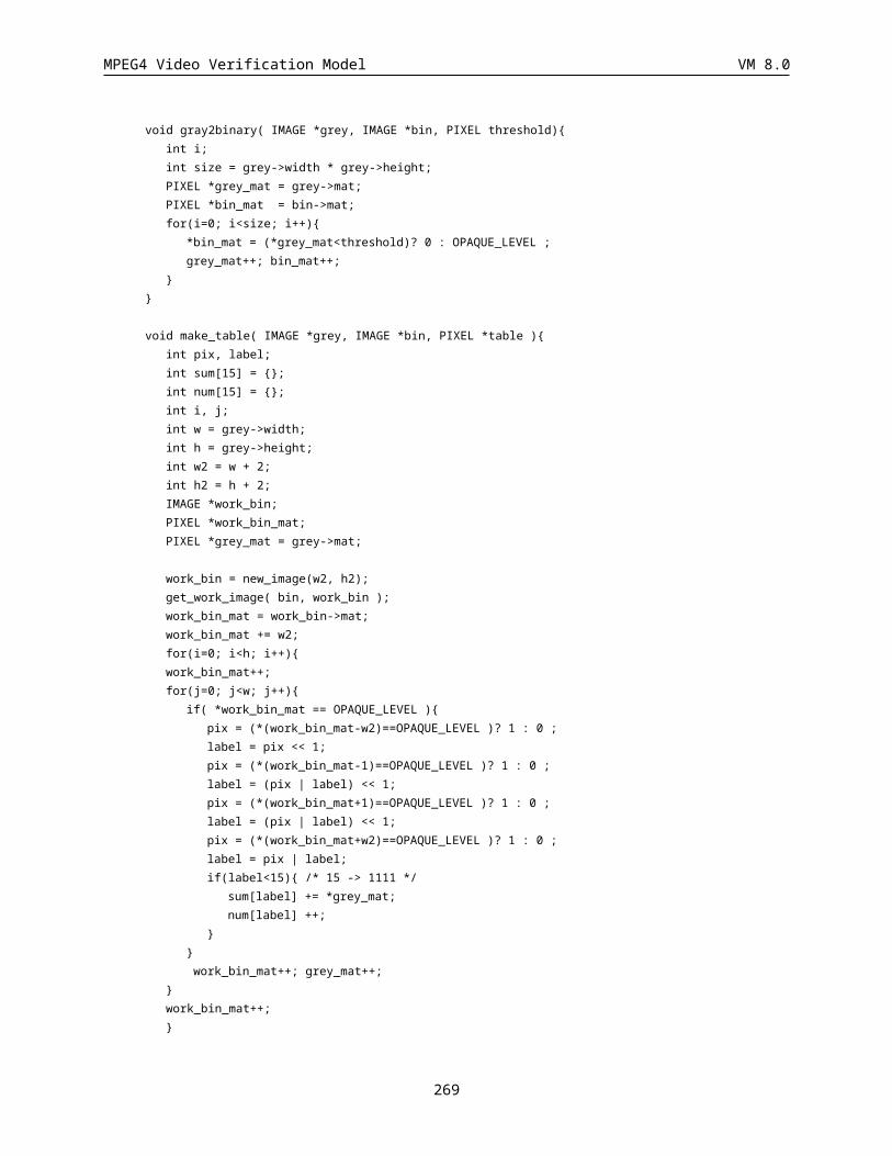
MPEG4 Video Verification Model VM 8.0
Frame target bit allocation
FrameTargtBit intra frame
inter frame
bitratefps
bitratefps
*5
Frame coded-bit estimation: There are 512 classes which are combinations of 32 macro block color classes(Mc) and 16 block variance classes(Bv). We can estimate the total number of coded bits in a frame with the histogram and the bit model table. FrameEstimatedBit is the estimated number of coded bit in the current frame
FrameEstimatedBit PrevShapeBit if Coded B R Mc Bv H Mc BvBvMc
( ) [ [ ]][ ]* [ ][ ]0
15
0
31
or
FrameEstimatedBit ShapeBit if Coded B R Mc Bv H Mc Bv T etBvMc
( ) [ [ ]][ ]* [ ][ ] arg0
15
0
31
In the above equation, B[Mc][Bv] is the number of bits in the bit table and H[Mc][Bv] is the computation result of the histogram when a block is classified into Bv. The histogram can be computed with the information of macro block classes and block classes of the previous frame because the current frame to be coded and the previous frame are very highly correlated. Therefore the real-time coding process is possible.
VOP texture-bit estimation
VOPEstimatedBit if Coded B Rq Mc Bv HVOP Mc Bv
BvMc
( ) [ [ ]][ ]* [ ][ ]0
15
0
31
14.5.3 Post-Encoding Stage
Update Rate-Distortion Model: After the encoding stage, the parameters for the RD model must be sought. Given the number of texture bits used to code the current VO, R[i], the quantization level, Q[i], and the sum of absolute difference, S[i], the algorithm calculates the parameters X1[i] and X2[i] for every VO.
Post-Frameskip Control: The post-frameskip control determines the value of N_skip_post. After the buffer has been updated, i.e., by adding the sum of bits for coding every VO and subtracting the number of bits to be removed per picture, then the post-frameskip control is invoked. Essentially, if the “virtual buffer” has exceeded 75% of the buffer size, the encoder will skip the upcoming frames so as to reduce the current buffer level. The virtual buffer level (VB) is given by:
VB = B + Bp - (N_skip_post+1)*Rp
269
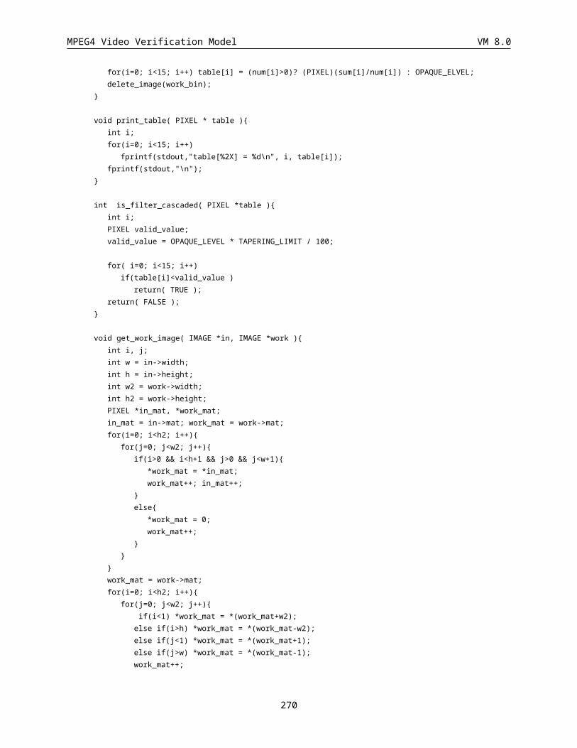
MPEG4 Video Verification Model VM 8.0
where the new variable, Bp, denotes the number of bits used in the previous frame. As before, B is the current buffer level and Rp is the number of bits removed from the buffer per picture. The above functionalities can be summarized in the psuedocode below:
Figure 1. Block diagram for multi-VO rate control
Post_Encoding()
{
B += Rc - Rp;/* update buffer fullness, Rc=bits for coded VO */
Rr -= Rc;/* update the remaining bit counts */
S[i] = Rc[i];/* update previous bit counts for every VO */
Hp[i] = Hc[i]; /* update previous header counts for every VO*/
Qp[i] = Qc[i]; /* update the previous quant level for every VO */
Nr[i]--;/* update the VO counter for every VO*/
UpdateRDModel(Qc[i],Rc[i],Ec[i],Hc[i],X1[i],X[i])/* estimation of a new model */
if (VB > 0.75 * Bs) {/* VB = virtual buffer level */
N_skip_post[i]++;
Nr[i]--;
B -= Rp;
}
270

MPEG4 Video Verification Model VM 8.0
N_skip[i] = N_skip_pre[i] + N_skip_post[i];
}
Please note that the above is implemented for a scheme in which all VO are coded at the same frame rate. This implies that the frameskip applies to every VO. The notion suggests that this will be extended to different frame rate coding, but a more complex buffering algorithm will be needed.
After the value of N_skip_post has been found the value of N_skip_pre is added to it. The determination of N_skip_pre will be discussed shortly. The time instant update is based on the total frames to be skipped N_skip = N_skip_pre + N_skip_post. Note that the only time that the time instant can be updated is after the post-frameskip control.
14.5.4 Pre-Encoding Stage
Target Estimation: The initial target bit rate is calculated based on the number of available bits for the segment and the number of bits used in the previous corresponding VO. A similar lower bound to the SVOP algorithm is used, where Rs: bit rate for sequence, Nr[i]: number of ith VO remaining, S[i]: bit count for coding previous ith VO.
Target_Estimation()
{
T[i]=Max{Rs/(30*numVOs), Rr/(Nr[i]*numVOs)}
T[i] = T[i] * 0.8 + S[i] * 0.2
}
Joint Buffer Control: The joint buffer control symbolizes the same operation as buffer control in SVOP rate control, however, the target is a sum of individual targets, i.e., T = sum of T[i].
Target Distribution: From the joint buffer control, a new total target is calculated. It is this target which will be distributed among the VO. The distribution is based on the size, the motion and the MAD2 of each object.
Target_Distribution()
{
valid = Check_target();
if(valid) {
for ( j = every MB in ith VO) {
/* calculate mean motion vector for ith VO */
MMV[i] = (abs(dx[j]) + abs(dy[j]))/N_mb[i];
271
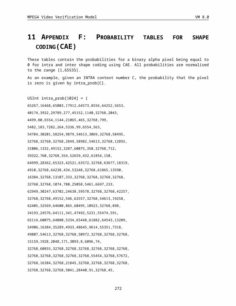
MPEG4 Video Verification Model VM 8.0
}
/* calculate MAD_SQ for ith VO */
MAD_SQ[i] = (error_sq[i])/N_mb[i];/* error_sq[i]: squared MAD of ith VO */
MAD2[i] = MAD_SQ[i]/MAD_SQ; /* MAD_SQ: sum of MAD_SQ[i] */
MOTION[i] = MMV[i]/MMV; /* MMV: sum of MMV[i] for all VO */
SIZE[i] = N_mb[i]/N_mb; /* N_mb[i]: MBs in ith VO */
/* N_mb: total MBs in picture */
T[i] = (MOTION[i]*wm + SIZE[i]*ws + MAD2[i]*wv)*T;
}
else {
T[i] = negative value;
}
}
The distribution is only executed when the target is valid. The target is valid when it is greater than the sum of header bits used for coding the previous frame. If it is not valid, all the targets are made negative. The negative targets will serve as a flag for clipping the quantization parameters. Also, if the target is negative, the value of N_skip_pre will be non-zero for the next time instant update. The routines below summarize the remaining steps of the pre-encoding stage.
int Check_target()
{
s = T - H; /* T: total target from joint buffer control */
/* H: sum of header bits for all VO */
if(s<0)
while(s<0) {
N_skip_pre++;
s += Rp; /* add number of bits to be removed from buffer/picture */
}
return(0); /* invalid target */
else
return(1); /* valid target */
}
Once the targets have been established, the quantization level for each object can be calculated individually.
272
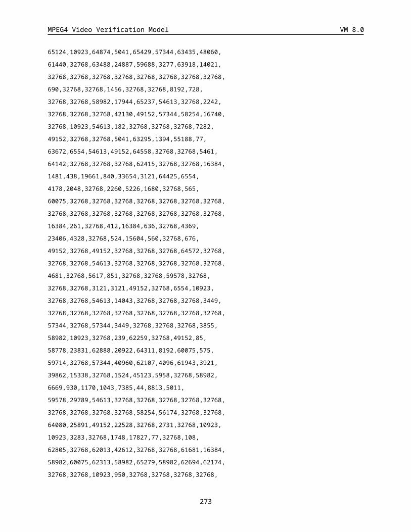
MPEG4 Video Verification Model VM 8.0
Quantization_Level_Calculation()
{
if (X2==0) Qc = X1*Ec/T;/* fall back 1st order mode */
else Qc= (2*X2*Ec)/(sqrt((X1*Ec)**2+4*X2*Ec*T)-X1*Ec) /* 2nd order mode */
/* clipping */
Qc = Min (ceil(Ql*1.25), Qc, 31);
if(negative target)
Qc = Max (ceil(Ql*0.75), Qc, LB_QUANT);
else
Qc = Max (ceil(Ql*0.75), Qc, 1);
}
The value of LB_QUANT limits the number of texture bits for cases in which the target is not even sufficient to code the header information. This safety measure assists in preventing overflow for coding the current frame. As a corrective measure, the value of N_skip_pre is applied to the next time coding instant.
14.5.5 Modes of Operation
As a means of regulating the trade-offs between spatial and temporal coding, two modes of operation are introduced: LowMode and HighMode. When encoding at high bit rates, the availability of bits allows the algorithm to be flexible in its target assignment to each VO. Under these circumstances, it is reasonable to impose homogeneous quality among each VO. Therefore, the inclusion of MAD2[i] is essential to the target distribution and should carry the highest weighting. On the other hand, when the availability of bits is limited, it is very difficult (if not impossible) to achieve homogeneous quality among the VO. Under these conditions, it is desirable to spend less bits on the background and more bits on the foreground. Consequently, the significance of the variance has decreased and the significance of the motion has increased. Based on the above arguments and experimental trial-and-error, the weights used in our experiments were: wm = 0.6, ws = 0.4, wv = 0.0 for LowMode and wm = 0.25, ws = 0.25, wv = 0.5 for HighMode.
Besides regulating the quality within each frame, it is also important to regulate the temporal quality as well, i.e., keep the frame skipping to a minimum. In HighMode, this is very easy to do since the availability of bits is plentiful. However, in LowMode, frame skipping occurs much more often. In fact, the number of frames being skipped is a good indication of which mode the algorithm should be operating. This is expressed as follows:
if (total_frames_skipped > SKIP_TH)
Operate in LowMode
else
Operate in HighMode
273
MPEG4 Video Verification Model VM 8.0
In the current implementation, the skip threshold was set to 2.
The decision process to obtain a mode of operation can also be seen as a constraint on the temporal resolution. If we are in LowMode, we know that the encoder has skipped some specified number of frames. To obtain a reasonable compromise between the spatial and temporal quality, LowMode will impose a lower bound on the calculated quantization parameter. This lower bound, LB_QUANT, is the same as that used in [MPEG97/1631] when the target from the joint buffer control was less that the amount of header bits used in the last frame.
14.5.6 Shape Rate Control
From section 3.2.1.5 of the VM, it is evident that the value of AlphaTH has considerable effect over the number of bits which will be spent on the shape information. In the following, a scheme is proposed for controlling the shape information based on the selection of the AlphaTH in light of the two modes of operation - LowMode and High Mode.
Assume that AlphaTH is initially set to AlphaINI. After the encoding stage, the rate control algorithm will determine the mode of operation, such that:
· If the mode of operation is LowMode then increment the current AlphaTH by AlphaINC;
· If the mode of operation is HighMode then decrement the current AlphaTH by AlphaDEC.
The maximum and minimum values of AlphaTH are AlphaMAX and 0, respectively. Recommended parameter values are AlphaMAX=12, AlphaINC=AlphaDEC=4 and AlphaINI=0.
14.5.7 Summary
The algorithms described in this section illustrates how the framework of the existing VM7.1 rate control is extended to multiple VO encoding. Automatic selection of quantization parameters for I-frame and first P-frame are used. Overall, the algorithm is able to successfully achieve the target bit rate, effectively code arbitrarily shaped objects, and maintain a stable buffer.
14.6 Joint Macroblock-Layer Rate Control
· Samsung’s technique [1] uses a model of the human visual system (HVS).
· Sarnoff’s technique [2] attempts to maintain a constant value of QP for the entire image. More appropriate for lower bit rates.
· Sharp’s [3] technique adapts QP with the energy of the block. More appropriate for higher bit rates.
274
MPEG4 Video Verification Model VM 8.0
14.6.1 Rate-Distortion Model
We model the number of bits Bi produced for the i-th macroblock :
B =
AQP
MAD Bitrate R
AQP
MADAQP
MAD Bitrate Ri
1
i2 i
2
2
i2 i
3
ii
;
;
(1)
* A1 , A2 and A3 are the model parameters,
* Bitrate is the rate in bits per pixel for the texture of VOP,
* R is a threshold. By default, we set R=0.085.
14.6.2 Target number of bits for each macroblock
Let N be the number of macroblocks in a VOP.
The target number of bits, Ti, for the i-th macroblock :
TW MAD
W MADTi
i i
j jj 1
N
,
(2)
where:
* Wi is a weight that indicates the perceptual importance of the i-th macroblock.
* T is the target number of bits for the DCT coefficients (luminance and chrominance components) of the VOP, which is the target frame bits from VM7.0’s frame-layer rate control [4] minus the bits for motion, shape, and syntax overhead.
If we combine (1) and (2), we obtain:
QP =MAD C K 1 C K 2i
2 i 1
2
=;;
(3)
275
MPEG4 Video Verification Model VM 8.0
* C1 is a function of A1, MAD1, …, MADN and T.
* C2 is a function of A2, A3, MAD1, …, MADN, and T.
14.6.3 The Macroblock Rate Control Technique
Step 1. Initialization.
N - number of macroblocks in the VOP ,
T - number of bits available for encoding the macroblocks’ texture
If first frame, let A1= A1_in= 100, A2= A2_in= 400, A3= A3_in= 0
Otherwise, let A1= A1_in , A2= A2_in, and A3= A3_in.
If Bitrate > R = 0.085, let K=1, otherwise let K=2.
Here, we set W1= W2= …=WN = 1, but could be obtained from [1].
Finally, let S W MAD1 j jj 1
N
.
Step 2. Compute QP for i_th macroblock
Let TW MAD
STi
i i
i
, the target number of bits per macroblock.
QP =MAD
AT
K 1
QAQ
MADAQ
MAD T K 2
i1
i
22 i
2 3i i
=;
: ;
Round QP to value in 1, …, 31, and QP change constrained by DQUANT.
Step 3. Encode Macroblock with QP
Step 4. Update Counters
Bi - number of bits used for i_th macroblock. Compute:
276
MPEG4 Video Verification Model VM 8.0
T T B i , S S W MADi 1 i i i , and TW MAD
STi 1
i 1 i 1
i 1
.
Step 5. Update A1 or A2, B
If K = 1, .AB
MADQP1
i
i2
2
Let
A A1i
Ai 1
i, A A
iN
+ AN i
N.1 1 1 1 1 1 _ prev
If K = 2, use linear regression to estimate A2 and A3 as in VM rate control [4]
Step 6. If i = N, Stop (all macroblocks are encoded), let Af_prev = Af for f =1,2,3.
Otherwise, i = i+1, and go to Step 2.
14.7 Boundary block mergingTo be included
14.8 3D VLC for intra codingto be included
277
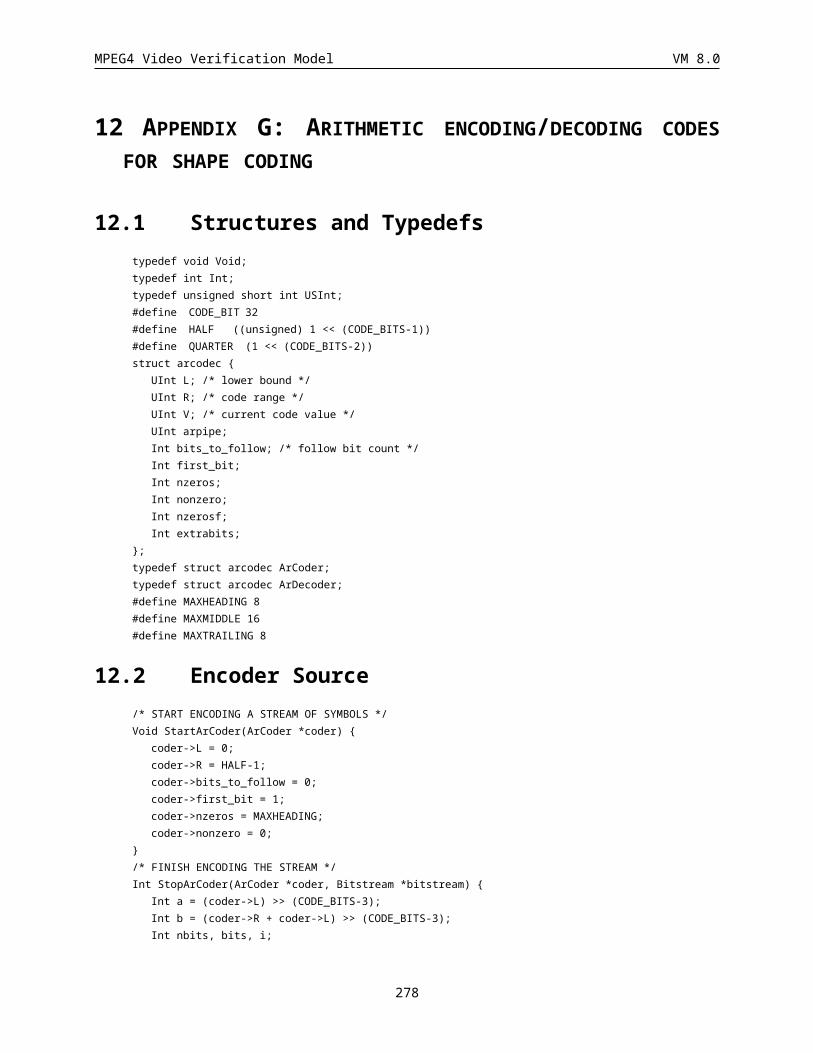
MPEG4 Video Verification Model VM 8.0
15MPEG-4 VIDEO VERSION MANAGEMENT
Technology CE VideoVM VisualWD Software
Ver. 8.0 Ver 4.0 Mo MS
I and P modes X X X XBinary shape X X X XAC/DC prediction X X X XPadding X X X XQuantization types X X X XSlice synchronization X X XOBMC mode X X X XB modes X X X XTemporal scalability rectangular shape X X (X)Temporal scalability (arbitrary shape) X X (X)Spatial scalability rectangular shape X X X XStatic sprites X X X XData partitioning X X XReversible VLC X X XScalable wavelet X X XInterlaced coding X XDynamic sprites X XGlobal motion compensation X XGray level alpha shape X X XEffects X (X)SA-DCT X X X X12 bit video XTemporal scalable shape coding XAdaptive 3D VLC XMatching pursuits XMultiple VO rate control X
278
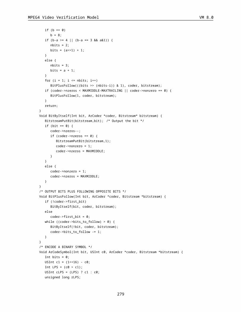
MPEG4 Video Verification Model VM 8.0
Macroblock rate control XFrame level rate control X X XShape adaptive wavelet X XSpatial scalable shape coding XBoundary block merging X¼ pel motion compensation XDynamic resolution conversion XVOP-CR XInterlaced shape coding XUniversal VLC for motion coding XArbitrary shape spatial scalability (texture) X X(Chroma-key shape coding)
Last update July 25th, 1997
279