Embed Size (px)
Citation preview

ECE734 Project Presentation
Conditioned Reflex Mimic Circuit Design
Gengyu Yang2013.5.10

Outline
• Introduction
• Digital Circuit Design
• Circuit Design Using RRAM
• Comparison and Discussion
• Conclusion

Outline
• Introduction
Pavlov’s dog
RRAM and memristor
• Digital Circuit Design
• Circuit Design Using RRAM
• Comparison and Discussion
• Conclusion

Introduction – Pavlov’s dog
• Ivan Petrovich Pavlov was a famous Russian physiologist
• Pavlov's dog are classical conditioning experiments using dogs by the Russian physiologist Ivan Pavlov

Introduction – Pavlov’s dog
• Three phases of the experiment• (1) before learning phase: the output of the circuit, which will be used to
simulate the strength of salivation, will generate value only associated with the food visual input signal but not with the ringing bell sound input signal.
• (2) learning phase: when a bell was rung in subsequent time with food being presented to the dog in consecutive sequences, the dog will initially salivate when the food is presented. The dog will later come to associate the ringing of the bell with the presentation of the food and salivate upon the ringing of the bell.
• (3) after learning phase: the output of the circuit will generate value associated with both the food visual input signal and the ringing bell sound input signal.

Introduction – RRAM & Memristor
• RRAM, a kind of novel memory
• small area, non-volatile, simple MIM crossbar structure, fast switching, low power consumption, compatibility with CMOS process, simple fabricating process
• Multilevel -- memristor
17 RRAM memories under atomic force microscope

Outline
• Introduction
• Digital Circuit Design
• Circuit Design Using RRAM
• Comparison and Discussion
• Conclusion

Simple version

Simple version

Circuit with food weight update

Circuit with food weight update
Circuit with inhibitory mechanism

Circuit with food weight update

Outline
• Introduction
• Digital Circuit Design
• Circuit Design Using RRAM
• Comparison and Discussion
• Conclusion

Simple version

Simple version

Complex version

Outline
• Introduction
• Digital Circuit Design
• Circuit Design Using RRAM
• Comparison and Discussion
• Conclusion

Area
a positive edge trigged 1 bit D flip-flop
Analog circuit:9 transistors2 resistances2 RRAM devicesTotal: the same area as 9 transistors
Digital circuit:2 1-bit D flip flop, 48 transistors2 adders: OR gate, 8 transistors2 multipliers: AND gate, 8 transistorsAND gate: 4 transistorsTotal: 68 transistors

Non-volatile memory & power consumption
• RRAM: non-volatile, pJ/spike (biological competitive)
• Digital circuit: needs to introduce other memory system to implement non-volatile memory, power problem

Outline
• Introduction
• Digital Circuit Design
• Circuit Design Using RRAM
• Comparison and Discussion
• Conclusion
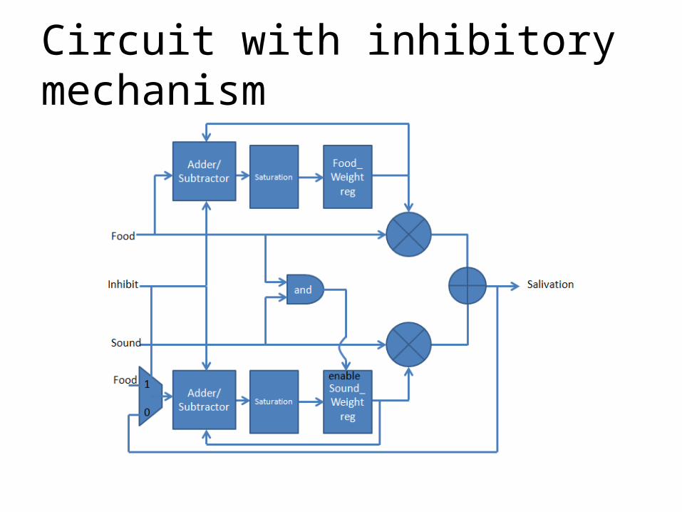
Conclusion
• Implement conditioned reflex mimic circuit• 3 versions of digital circuit• 2 versions of circuit using RRAM• Circuits using RRAM have better performance
regarding area, non-volatile memory, and power consumption

Thank you!&
Questions?


![Taqleed (Mimic) [English]](https://img.pdfslide.us/doc/110x75/577ce0831a28ab9e78b37d12/taqleed-mimic-english.jpg)