Embed Size (px)
Citation preview
A minerals research contract report October 1980
VISUAL DISPLAY ND CONTROL SYSTEM
Contract J0177020 Arthur D. Little, Inc.
BUREAU OF MINES * UNITED STATES DEPARTMENT OF THE INTERIOR Minerals Health and Safety Technology
The views and conclusions contained in this document
are those of the authors and should not be inter-
preted as necessarily representing the official
policies of the Interior Department's Bureau of Mines
or of the U.S. Government.
Arthur D Little Inc.
I 4. TltIm and Subtitle
Development o f a V i s u a l D i s p l a y and
50m - MI
C o n t r o l Sys t em - - - -- --
7. Author(~)
1 . - - - . - -. - -- - - - -- . 9. Pmdormlng O ~ a n i z a t l o n Name and A d d r e ~ r
3. Recipient's Access~on No
A r t h u r D . L i t t l e , I n c . Acorn P a r k Cambr idge , MA 02140
2. REPORT DOCUMENTATION PAGE
5. Report Date ( O c t o b e r 1980
1. 00.
8. Per form~ng Orarnlzat~on Rept. No
C-80956 . .
10. Pm)ect/Task/Work Unit No.
I I. ContractfC) or Crrnt(C) No.
50177020
(C)
I it. Sponsorin# Or~anizat ion Name and Address ' 13. Type of Report 6 Period Covered I I I P i t t s b u r g h Min ing a n d S a f e t y R e s e a r c h C e n t e r
U n i t e d S t a t e s Bu reau of Mines
P i t t s b u r g h 9 Pennsy l van i a_ - - - - -- -- . A - - - - - - - - -- - --
15. Supplementary Notes
F i n a l /
. - - - - -- - - - - - - - - - 16. Abstract (Llmlt. 100 words)
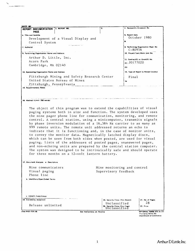
The o b j e c t o f t h i s p rog ram was t o e x t e n d t h e c a p a b i l i t i e s o f v i s u a l p a g i n g s y s t e m s b o t h i n s i z e a n d f u n c t i o n . The s y s t e m d e v e l o p e d u s e s t h e mine p a g e r phone l i n e f o r c o m m u n i c a t ~ i o n , m o n i t o r i n g , a n d r e m o t e c o n t r o l . A c e n t r a l s t a t i o n , u s i n g a m in i - compu te r , t r a n s m i t s s i g n a l s by p h a s e i n v e r s i o n m o d u l a t i o n o f a 1 6 , 3 8 4 Hz c a r r i e r t o a s many a s 999 r e m o t e u n i t s . The r e m o t e u n i t a d d r e s s e d r e t u r n s a n e c h o t o i n d i c a t e t h a t i t i s f u n c t i o n i n g a n d , i n t h e c a s e of m o n i t o r u n i t s , t o convey t h e m o n i t o r d a t a . M a g n e t i c a l l y l a t c h e d d i s p l a y d i s c s , wh ich c a n be s e e n f rom b o t h s i d e s when p o s t e d , a r e u s e d f o r v i s u a l p a g i n g . L i s t s o f t h e a d d r e s s e s o f p o s t e d p a g e s , unanswered p a g e s , a n d non -echo ing u n i t s a r e p r e p a r e d by t h e c e n t r a l s t a t i o n c o m p u t e r . The s y s t e m was d e s i g n e d t o be i n t r i n s i c a l l y s a f e a n d s h o u l d o p e r a t e f o r t h r e e months on a 1 2 - v o l t l a n t e r n b a t t e r y .
Mine commun ica to r s V i s u a l p a g i n g Phone l i n e
Mine m o n i t o r i n g a n d c o n t r o l S u p e r v i s o r y f e e d b a c k
b Identl f l+n/Opon Ended Terms
c COSATl f ~e ld /G roup - - - - - .. -
1
18. Availablllty Statement / IS). Secur~ty Class l T h ~ r Report)
U n c l a s s i f i e d R e l e a s e u n l i m i t e d )D. security class (T~I . r) 1 22. Price
~ n c l a s s i f i e a I
(S.0 ANSI-239.18) See Inrtruct lonr on Reversa OPTIONAL FORM 272 (4-771 (Formerly NT lE35 ) Ueprrtnrent of Commerce
Arthur D Little Inc
FOREWORD
T h i s r e p o r t was p r e p a r e d by A r t h u r D. L i t t l e , I n c . ,
Cambr idge , MA 02140 u n d e r USIBM C o n t r a c t Number
50177020 . The c o n t r a c t was i n i t i a t e d u n d e r t h e Coa l
Mine H e a l t h a n d S a f e t y Program. I t was a d m i n i s t e r e d
u n d e r t h e t e c h n i c a l d i r e c t i o n o f t h e P i t t s b u r g h
Min ing a n d S a f e t y R e s e a r c h C e n t e r w i t h M r . H a r r y
D o b r o s k i a c t i n g a s T e c h n i c a l P r o j e c t O f f i c e r . M r .
Doyne W . T e e t s was t h e c o n t r a c t a d m i n i s t r a t o r f o r t h e
Bureau o f Mines . T h i s r e p o r t i s a summary o f t h e work
r e c e n t l y c o m p l e t e d a s a p a r t o f t h i s c o n t r a c t d u r i n g
t h e p e r i o d Augus t 1977 t o Oc tob l e r 1980 . T h i s r e p o r t
was s u b m i t t e d by t h e a u t h o r s i n O c t o b e r 1980 .
Arthur D Little, Inc.
TABLE OF CONTENTS
I Item
List of Illustrations
List of Tables
INTRODUCTION
PHASE I -- ESTABLISH THE SYSTEM FUNCTIONAL REQUIREMENTS
System Architecture
System Size
Special Requirements for Remote Units
Signal Transmission
PHASE I1 -- DESIGN THE SYSTEM
PHASE 111 -- FABRICATE THE SYSTEM
PHASE IV -- EVALUATE THE SYSTEM PERFORMANCE
CONCLUSIONS
INVENTIONS
Page
Arthur D Little, Inc.
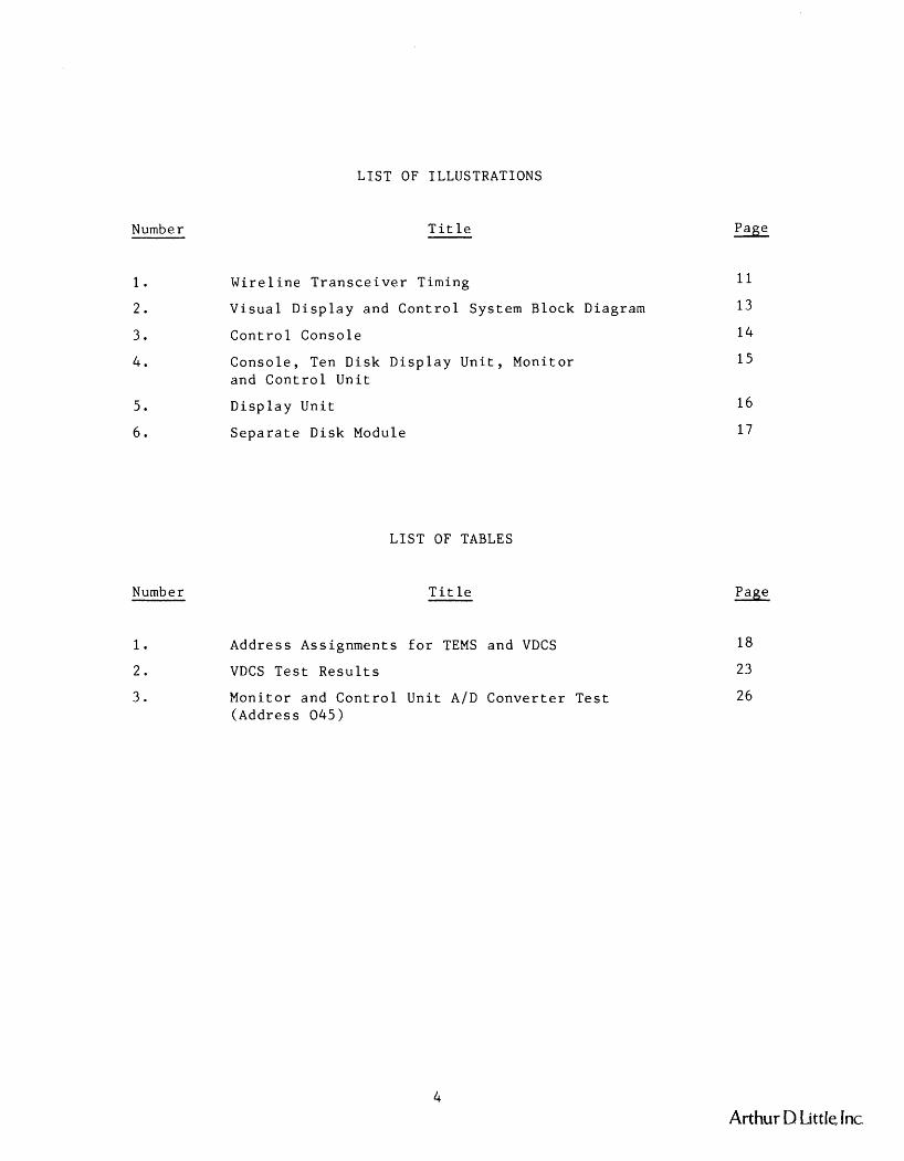
LIST OF ILLUSTRATIONS
Number
Number
Title
Wireline Transceiver Timing
Visual Display and Control System Block Diagram
Control Console
Console, Ten Disk Display Unit, Monitor and Control Unit
Display Unit
Separate Disk Module
LIST OF TABLES
Title
Address Assignments for TEMS and VDCS
VDCS Test Results
Monitor and Control Unit A/D Converter Test (Address 045)
Page
Page
Arthur D Little, Inc.
INTRODUCTION
The original objective of this program was to obtain a mineworthy
optical/electromagnetic pager system that will alert supervisory,
maintenance or other mine personnel that they are being paged on the
mine pager phone system. The program goal was subsequently broadened to
add monitor and control capability to the paging system, which was then
renamed Visual Display and Control System (VDCS). Those objectives were
achieved in a four-phase program:
Phase I -- Establish the system functional requirements Phase I1 -- Design the system Phase I11 -- Fabricate the system
Phase IV -- Evaluate the system performance.
The resulting Visual Display and Control System has a total capacity of
1000 addresses and is under the control of a central unit at which
commands are dispatched and responses received. The VDCS as delivered
has 23 addresses assigned to visual pager disks, three addresses
assigned to relay control functions, and three addresses assigned to
monitor functions. Since the central unit is microprocessor-controlled,
the system has great flexibility and changes are easily incorporated.
Arthur D Little, Inc.
PHASE I - ESTABLISH THE SYSTEM FUNCTIONAL REQUIREMENTS
The original purpose of the zone pager development program was to
expand the capabilities of the visual pager developed under Contract
H0252093. Early in the study it became apparent that the twisted pair
pager phone line is a valuable resource, since it reaches most of the
mine workings and could therefore be used for remote monitoring and
control as well as paging. By adapting this broader view of the system
capabilities at the beginning of the design process, it was possible to
accommodate those additional functions at a later date.
The system functional requirements were arrived at through discussions
with mine operators and Bureau of Mines personnel. The genesis and
rationale of those requirements are disczussed in detail in the Arthur
D. Little Phase I report (1) - and are sunnmarized here.
System Architecture
The main guiding principle in choosing a system architecture was
preservation of flexibility to modify functions or add new ones. To
that end, the system components and functions were specified as follows:
1. A central control unit to be located at the pit head or mine
office. This unit will transmit signals to remote units on
the phone line and receive answering signals from the remote
units. The central control unit will use a microprocessor and
be programmed to perform the desired functions. System
flexibility will be achieved through programming the central
unit. The system is to contain a supervisory control loop
(1) - Arthur D. Little, Inc., Development of a Zone-Type and Single-Unit
Visual Display System. Phase I report under Bureau of Mines Contract
50177020, ADL Case 80956.
Arthur D Little, Jnc
whereby e a c h r emo te u n i t , when i n t e r r o g a t e d , e c h o e s i t s
a d d r e s s and t h e command i t r e c e i v e d . T h i s e c h o i s c h e c k e d
a g a i n s t t h e t r a n s m i t t e d d a t a t o d e t e c t m a l f u n c t i o n i n g r emo te
u n i t s . The a d d r e s s i n g s y s t e m must i n c l u d e g l o b a l a d d r e s s e s
which p e r m i t a c t i v a t i o n o f m u l t i p l e d i s p l a y modules w i t h a
s i n g l e command. M o n i t o r u n i t o u t p u t s a r e t o be l o g g e d on a
h a r d copy d e v i c e . Communicat ions c h a n n e l e r r o r s w i l l be
i n d i c a t e d on t h e c o n s o l e and t h e i r d e t a i l s w i l l b e l ogged on
t h e h a r d copy d e v i c e . The c o n s o l e w i l l p r o v i d e a means t o
d i s p l a y a l i s t o f a l l r emo te u n i t s which have been p o s t e d
d u r i n g t h e l a s t f i v e m i n u t e s , a l i s t o f a l l u n i t s which have
b e e n p o s t e d s i n c e s y s t e m r e s e t , and a l i s t of a l l u n i t s which
h a v e had communica t i on e r r o r s .
V i s u a l p a g e r r emo te u n i t s l o c a t e d i n t h e mine . These w i l l be
made up f rom s i n g l e d i s k d i s p l a y m o d u l e s , e a c h o f which h a s a
u n i q u e a d d r e s s . Each module co ln t a in s a two- inch d i a m e t e r
numbered o r l e t t e r e d d i s k which c a n b e r o t a t e d t o e i t h e r a
h o r i z o n t a l o r v e r t i c a l p o s i t i o n s o t h a t t h e d i s k i s e i t h e r
i n v i s i b l e o r v i s i b i e . M u l t i p l e d i s p l a y u n i t s w i l l c o n s i s t o f
t h e r e q u i r e d number o f s i n g l e d i s k modu le s mounted i n a
common h o u s i n g . Each module w i l l have a u n i q u e a d d r e s s s o
t h a t i t c a n be i n d i v i d u a l l y s e l e c t e d by t h e c e n t r a l con-
t r o l l e r . A l l communica t i ons w i l l be i n i t i a t e d by t h e c e n t r a l
c o n t r o l l e r . Upon r e c e i v i n g i t s a d d r e s s and a coded o p e r a t i o n
i n s t r u c t i o n , t h e v i s u a l p a g e r u n i t w i l l e c h o back t h e a d d r e s s
and t h e o p e r a t i o n c o d e . These u n i t s w i l l r e s p o n d t o t h r e e
o p e r a t i o n c o d e s : p o s t , which w i l l s e t t h e d i s p l a y d i s k t o
p o s t a p a g e ; c l e a r , wh ich w i l l r e s e t t h e d i s p l a y d i s k t o
c l e a r a p a g e ; and t e s t , which e c h o e s t h e a d d r e s s and command
b u t d o e s n o t c h a n g e t h e s t a t e o f t h e d i s p l a y .
Arthur D Little. Inc.
3 . M o n i t o r u n i t s l o c a t e d i n t h e mine . These w i l l h a v e t h e i r
own i n d i v i d u a l a d d r e s s e s l i k e t h e v i s u a l p a g e r u n i t s a n d
w i l l r e s p o n d t o c a l l s i n i t i a t e d by t h e c e n t r a l c o n t r o l
u n i t . The e c h o r e s p o n s e f rom ia m o n i t o r u n i t w i l l c o n s i s t o f
t h e u n i t a d d r e s s w i t h measurement d a t a r e p l a c i n g t h e
o p e r a t i o n c o d e . The i n p u t v o l t a g e r a n g e f o r m o n i t o r u n i t s
i s 0 t o 4 .92 v o l t s . Wi th a s i x b i t A / D c o n v e r t e r , t h e l e a s t
s i g n i f i c a n t b i t r e p r e s e n t s a n i n c r e m e n t of 0 .078125 v o l t s .
4 . Remote c o n t r o l u n i t s l o c a t e d i n t h e mine . These w i l l
p r o v i d e f o r r emo te c o n t r o l o f pumps, f a n s , r e g u l a t o r s o r
o t h e r equ ipmen t i n t h e mine . Each w i l l h a v e i t s own
i n d i v i d u a l a d d r e s s a n d w i l l e c h o t h i s a d d r e s s a n d o p e r a t i o n
c o d e when c a l l e d by t h e c e n t r ( a 1 c o n t r o l u n i t . The p o s t
command w i l l c l o s e a p a i r o f r e l a y c o n t a c t s i n t h e r e m o t e
u n i t , t h e c l e a r command w i l l open t h e r e l a y c o n t a c t s , a n d
t h e t e s t command o p e r a t e s a s i n t h e v i s u a l p a g e r u n i t s . The
r e l a y c o n t a c t s a r e r a t e d a t 120 v o l t s AC a n d f i v e a m p e r e s ,
n o n i n d u c t i v e .
The a c t u a l s y s t e m wh ich was d e l i v e r e d c l o n s i s t s o f t h r e e s i n g l e d i s k
d i s p l a y u n i t s , two f i v e - d i s k d i s p l a y u n i t s , one t e n - d i s k d i s p l a y
u n i t , a c e n t r a l c o n t r o l u n i t w i t h h a r d copy d e v i c e , a n d a
m o n i t o r / c o n t r o l u n i t h a v i n g t h r e e monitlor a n d t h r e e c o n t r o l modu le s .
Sys t em S i z e
The s y s t e m i s t o h a v e t h e c a p a b i l i t y o f a d d r e s s i n g 1000 r emo te u n i t s ,
i n c l u d i n g g l o b a l a d d r e s s e s .
Arthur D Little, Jnc
S ~ e c i a l R e a u i r e m e n t s f o r Remote U n i t s
The r e m o t e u n i t s o f a l l t y p e s l o c a t e d u n d e r g r o u n d must be d e s i g n e d t o
meet some r a t h e r r e s t r i c t i v e r e q u i r e m e n t s . I n a d d i t i o n t o t h e r u g g e d
c o n s t r u c t i o n n e e d e d t o s u r v i v e i n a mine e n v i r o n m e n t , t h e s e i n c l u d e :
Underground u n i t s mus t b e i n t r i n s i c a l l y s a f e . T h e r e f o r e , t h e s e
u n i t s mus t u s e b a t t e r y power and draw v e r y l i t t l e c u r r e n t i n t h e
s t a n d b y s t a t e ( t h a t i s , when n o t r e s p o n d i n g t o s i g n a l s f rom t h e
c e n t r a l c o n t r o l u n i t ) . T y p i c a l t w e l v e - v o l t b a t t e r i e s h a v e a b o u t
t e n ampere-hour c a p a c i t y and w i l l g i v e t h r e e m o n t h s 1 s e r v i c e a t
a two m i l l i a m p e r e r a t e . T h i s p rob l em was s o l v e d i n t h e p r e v i o u s
v i s u a l p a g e r by u s i n g a dc "wake-up" s i g n a l on t h e phone l i n e t o
t u r n on t h e r e c e i v e r power . A s i m i l a r t e c h n i q u e w i l l b e u s e d i n
t h i s a p p l i c a t i o n , e x c e p t a c a r r i e r f r e q u e n c y t o n e b u r s t w i l l b e
u s e d a s t h e "wake-up" s i g n a l .
The u n d e r g r o u n d u n i t s mus t b e c o n n e c t e d t o t h e phone l i n e a l l
t h e t i m e a n d t h e r e f o r e mus t n o t l o a d t h e l i n e . The c h a r a c -
t e r i s t i c impedance o f a p a g e r phone l i n e i s a b o u t 1 3 5 ohms.
The VDCS u n i t s mus t h a v e a n i n p u t impedance much h i g h e r t h a n
t h i s . The v i s u a l p a g e r r e c e i v e r h a d a 40 k i l o h m impedance .
The VDCS r e c e i v e r impedance w i l l b e a b o u t a s h i g h .
VDCS r e c e i v e r s b o t h above and be low g r o u n d must a c c e p t s i g n a l s
o v e r a w i d e r a n g e o f power. The a t t e n u a t i o n of t h e phone l i n e
c a n b e a s h i g h a s 3 dB p e r m i l e a n d , i n a d d i t i o n , t h e r e a r e
l o s s e s b e c a u s e o f impedance misrnatch ( l o w impedance p a g e r
p h o n e s ; i n p a r t i c u l a r , t h e MSA p a g e r I a n d I1 p h o n e s , and
b r a n c h e s o r t a p s on t h e l i n e ) . These r e f l e c t i v e l o s s e s c o u l d
t o t a l 20 dB. S i n c e n o i s e on t h e phone l i n e i s e x p e c t e d t o b e
a b o u t 3 5 m i l l i v o l t s i n a 500 Hz bandwid th ( 2 ) , t h e r e c e i v e r s - (2) - N.B.S. Technical Note 654 , Electromagnetic Noise in Robena No. 4
Coal Mine. April 1974.
Arthur D Little, Inc.
should be designed to detect signals as small as about
100 millivolts. Maximum transmittler power will be about 1 watt
or about 10 volts rms on a 135-ohm impedance line. Therefore,
the receivers must work well over at least a 40 dB range and
be protected against transients.
Signal Transmission
The signals for the zone pager are transmitted by phase inversion
modulation of a carrier frequency. This method of modulation has the
advantages that it is easy to modulate and demodulate the signal and
that it is highly efficient. Most of the transmitted power is
contained in the sidebands which convey the information. Only a small
amount of power remains at the carrier frequency.
The carrier frequency was chosen in the range of 10 to 20 kilohertz.
The spectral density of noise on the pager phone line has a broad
minimum at about 16 kilohertz (2). - Noise increases significantly below
this frequency. Attenuation increases with frequency by about
0.25 d~/mile in this octave. The exact frequency does not seem to be a
critical parameter, and the selection of this frequency was made
during the detailed design phase, based on the availability of
suitable oscillator crystals. The standard electronic watch crystal
(32,768 Hz) is used to produce a 16,384--Hz carrier frequency and a
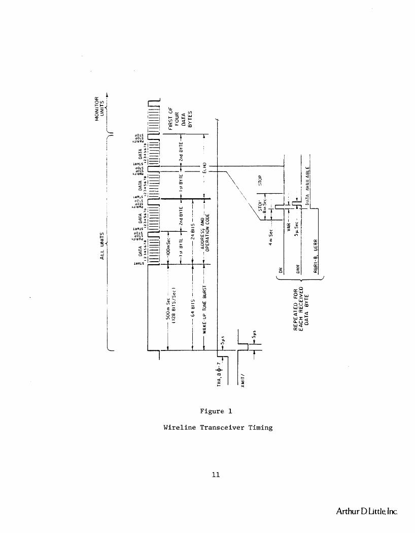
128 bit per second data rate. The signal format is shown in Figure 1.
An initial tone burst is used to "wake up" the remote units. This is
followed by two bytes, each containing a start bit, eight data bits, a
parity bit, and two stop bits. The remotte unit echoes back two bytes.
Display units and control units echo the address and command code for
verification of the communication path. Monitor units echo the address
and the six bits of measured data.
Arthur D Little, Inc.
K A o m e h i Z Z I
P'i I
Figure! 1
W i r e l i n e T r a n s c e i v e r Timing
Arthur D Little, Inc.
PHASE I1 - DESIGN THE SYSTEM
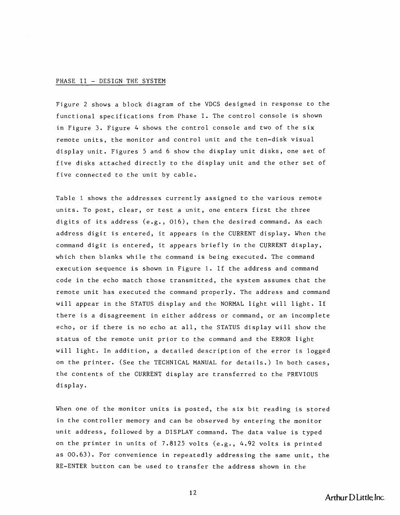
F i g u r e 2 shows a b l o c k d i ag ram of t h e VDCS d e s i g n e d i n r e s p o n s e t o t h e
f u n c t i o n a l s p e c i f i c a t i o n s f rom P h a s e I . The c o n t r o l c o n s o l e i s shown
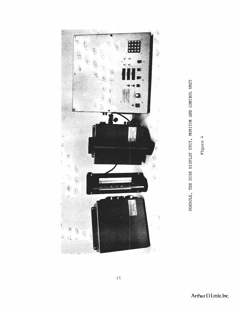
i n F i g u r e 3. F i g u r e 4 shows t h e c o n t r o l c:onsole a n d two o f t h e s i x
r e m o t e u n i t s , t h e m o n i t o r and c o n t r o l u n i t and t h e t e n - d i s k v i s u a l
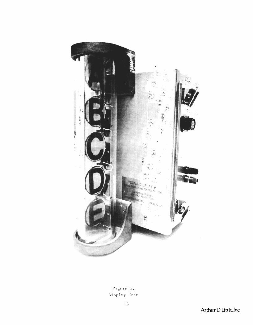
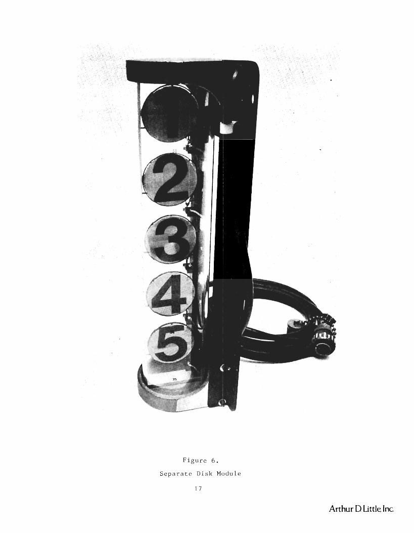
d i s p l a y u n i t . F i g u r e s 5 and 6 show t h e d i s p l a y u n i t d i s k s , one s e t o f
f i v e d i s k s a t t a c h e d d i r e c t l y t o t h e d i s p l a y u n i t a n d t h e o t h e r s e t o f
f i v e c o n n e c t e d t o t h e u n i t by c a b l e .
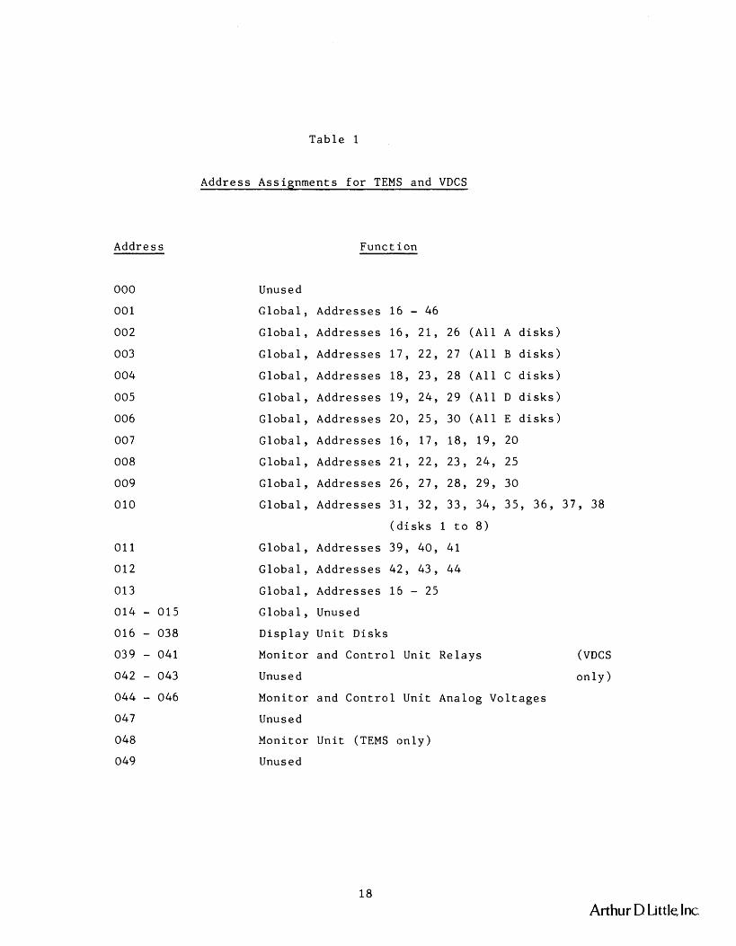
T a b l e 1 shows t h e a d d r e s s e s c u r r e n t l y a s s i g n e d t o t h e v a r i o u s r e m o t e
u n i t s . To p o s t , c l e a r , o r t e s t a u n i t , one e n t e r s f i r s t t h e t h r e e
d i g i t s o f i t s a d d r e s s ( e . g . , 0 1 6 ) , t h e n t h e d e s i r e d command. A s e a c h
a d d r e s s d i g i t i s e n t e r e d , i t a p p e a r s i n t h e CURRENT d i s p l a y . When t h e
command d i g i t i s e n t e r e d , i t a p p e a r s b r i e f l y i n t h e CURRENT d i s p l a y ,
which t h e n b l a n k s w h i l e t h e command i s b e i n g e x e c u t e d . The command
e x e c u t i o n s e q u e n c e i s shown i n F i g u r e 1. I f t h e a d d r e s s and command
c o d e i n t h e echo match t h o s e t r a n s m i t t e d , t h e s y s t e m a s sumes t h a t t h e
r e m o t e u n i t h a s e x e c u t e d t h e command p r o p e r l y . The a d d r e s s and command
w i l l a p p e a r i n t h e STATUS d i s p l a y a n d t h e NORMAL l i g h t w i l l l i g h t . I f
t h e r e i s a d i s a g r e e m e n t i n e i t h e r a d d r e s s o r command, o r a n i n c o m p l e t e
e c h o , o r i f t h e r e i s no echo a t a l l , t h e STATUS d i s p l a y w i l l show t h e
s t a t u s o f t h e r emo te u n i t p r i o r t o t h e command and t h e ERROR l i g h t
w i l l l i g h t . I n a d d i t i o n , a d e t a i l e d d e s c r i p t i o n of t h e e r r o r i s l o g g e d
on t h e p r i n t e r . ( S e e t h e TECHNICAL MANUAL f o r d e t a i l s . ) I n b o t h c a s e s ,
t h e c o n t e n t s of t h e CURRENT d i s p l a y a r e t r a n s f e r r e d t o t h e PREVIOUS
d i s p l a y .
When one of t h e m o n i t o r u n i t s i s p o s t e d , t h e s i x b i t r e a d i n g i s s t o r e d
i n t h e c o n t r o l l e r memory and c a n b e o b s e r v e d by e n t e r i n g t h e m o n i t o r
u n i t a d d r e s s , f o l l o w e d by a DISPLAY command. The d a t a v a l u e i s t y p e d
on t h e p r i n t e r i n u n i t s o f 7 .8125 v o l t s ( e . g . , 4.92 v o l t s i s p r i n t e d
a s 0 0 . 6 3 ) . Fo r c o n v e n i e n c e i n r e p e a t e d l y a d d r e s s i n g t h e same u n i t , t h e
RE-ENTER b u t t o n c a n be u s e d t o t r a n s f e r t h e a d d r e s s shown i n t h e
Arthur D httle, Inc
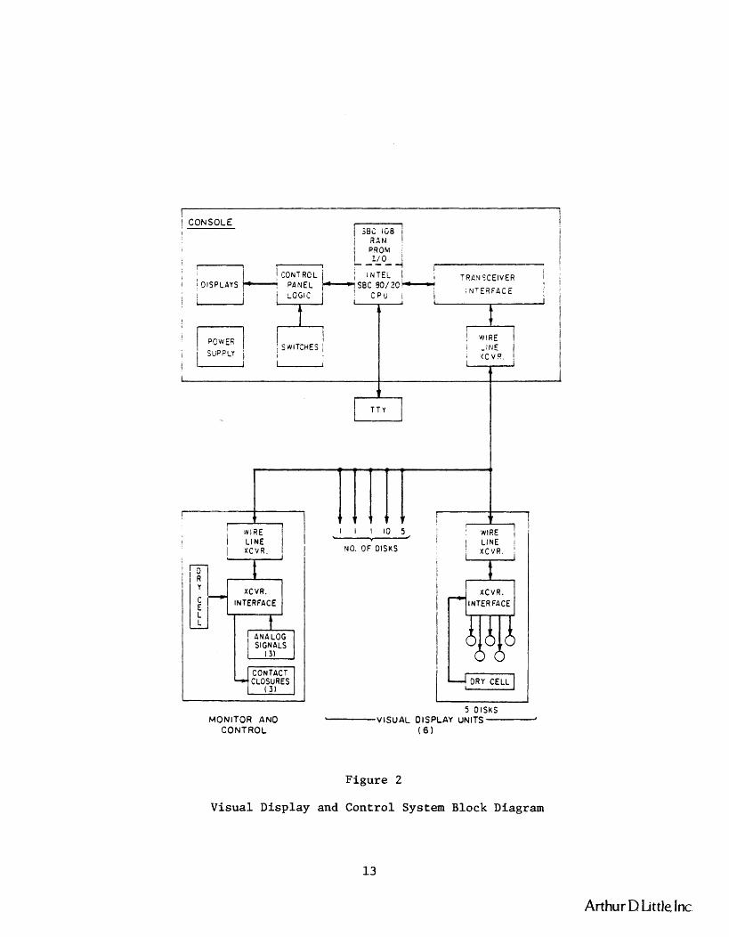
Figure 2
Visual Display and Control System Block Diagram
- r - - I ! CONSOLE i I m7
1 3 1 M 1 1
I I I
I I
PC W €6 I
SfllTCHES I I ,if15 I I jbPPLY
I
1 I CCVQ ,
I - I
A
1
1
Arthur D Little, Inc.
I
1
7 7 - - 7 4
I I r t I NlRE
I 1 LINE
t t ~ r v t I I l l 0 5 I A NIRE I I - LINE
I xC1/R. \
I hJ0. C)F DlSWS XCvR I I
I i L R .
I INTERFACE
1 D R Y CELL
xCvR.
5 DISKS MONITOR AN0 "--------VISUAL OISPLAY UNITS-
CONTROL ( 6
-+
ANALOG SIGNALS
( 3 )
CONTACT CLOSURES
( 3 1
F i g u r e 3 .
c o n t r o l C o n s o l e
Arthur D Little Inc
CO
NSO
LE
, T
EN
DIS
K D
ISP
LA
Y U
NIT
, M
ON
ITO
R
AN
D
CO
NTR
OL
UN
IT
Figure 4
F i g u r e 5.
D i s p l a y Unit
Arthur D Little, Inc
F i g u r e 6 .
Separa te Disk Module
1 7
Artt lur D Little Inc
Address
Table 1
Address Assignments for TEMS and VDCS
Function --
Unused
Global, Addresses 16 - 46 Global, Addresses 16, 21, 26 (All A disks)
Global, Addresses 17, 22, 27 (All B disks)
Global, Addresses 18, 23, 28 (All C disks)
Global, Addresses 19, 24, 29 (All D disks)
Global, Addresses 20, 25, 30 (All E disks)
Global, Addresses 16, 17, 18, 19, 20
Global, Addresses 21, 22, 23, 24, 25
Global, Addresses 26, 27, 28, 29, 30
Global, Addresses 31, 32, 33, 34, 35, 36, 37, 38
(disks 1 to 8)
Global, Addresses 3'9, 40, 41
Global, Addresses 42, 43, 44
Global, Addresses 16 - 25
Global, Unused
Display Unit Disks
Monitor and Control Unit Relays
Unused
Monitor and Control Unit Analog Voltages
Unused
Monitor Unit (TEMS only)
Unused
(VDCS
only)
Arthur D Little, Inc.
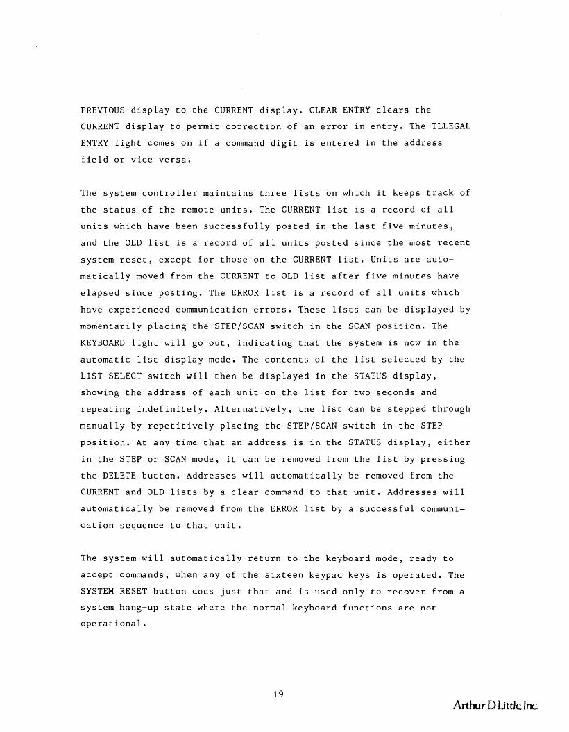
PREVIOUS d i s p l a y t o t h e CURRENT d i s p l a y . CLEAR ENTRY c l e a r s t h e
CURRENT d i s p l a y t o p e r m i t c o r r e c t i o n o f a n e r r o r i n e n t r y . The ILLEGAL
ENTRY l i g h t comes o n i f a command d i g i t i s e n t e r e d i n t h e a d d r e s s
f i e l d o r v i c e v e r s a .
The s y s t e m c o n t r o l l e r m a i n t a i n s t h r e e l i s t s on which i t k e e p s t r a c k o f
t h e s t a t u s o f t h e r e m o t e u n i t s . The CURRENT l i s t i s a r e c o r d o f a l l
u n i t s which h a v e b e e n s u c c e s s f u l l y p o s t e d i n t h e l a s t f i v e m i n u t e s ,
and t h e OLD l i s t i s a r e c o r d o f a l l u n i t s p o s t e d s i n c e t h e mos t r e c e n t
s y s t e m r e s e t , e x c e p t f o r t h o s e on t h e CURRENT l i s t . U n i t s a r e a u t o -
m a t i c a l l y moved f rom t h e CURRENT t o OLD llist a f t e r f i v e m i n u t e s have
e l a p s e d s i n c e p o s t i n g . The ERROR l i s t i s a r e c o r d o f a l l u n i t s wh ich
h a v e e x p e r i e n c e d communica t ion e r r o r s . These l i s t s c a n b e d i s p l a y e d by
m o m e n t a r i l y p l a c i n g t h e STEPISCAN s w i t c h i n t h e SCAN p o s i t i o n . The
KEYBOARD l i g h t w i l l g o o u t , i n d i c a t i n g t h a t t h e s y s t e m i s now i n t h e
a u t o m a t i c l i s t d i s p l a y mode. The c o n t e n t s o f t h e l i s t s e l e c t e d by t h e
LIST SELECT s w i t c h w i l l t h e n b e d i s p l a y e d i n t h e STATUS d i s p l a y ,
showing t h e a d d r e s s o f e a c h u n i t on t h e llist f o r two s e c o n d s a n d
r e p e a t i n g i n d e f i n i t e l y . A l t e r n a t i v e l y , t h e l i s t c a n b e s t e p p e d t h r o u g h
m a n u a l l y by r e p e t i t i v e l y p l a c i n g t h e STEPISCAN s w i t c h i n t h e STEP
p o s i t i o n . A t a n y t i m e t h a t a n a d d r e s s i s i n t h e STATUS d i s p l a y , e i t h e r
i n t h e STEP o r SCAN mode, i t c a n b e removed f rom t h e l i s t by p r e s s i n g
t h e DELETE b u t t o n . A d d r e s s e s w i l l a u t o m a t : i c a l l y b e removed f rom t h e
CURRENT a n d OLD l i s t s by a c l e a r command t o t h a t u n i t . A d d r e s s e s w i l l
a u t o m a t i c a l l y b e removed f rom t h e ERROR l i s t by a s u c c e s s f u l communi-
c a t i o n s e q u e n c e t o t h a t u n i t .
The s y s t e m w i l l a u t o m a t i c a l l y r e t u r n t o t h e k e y b o a r d mode, r e a d y t o
a c c e p t commands, when a n y o f t h e s i x t e e n keypad k e y s i s o p e r a t e d . The
SYSTEM RESET b u t t o n d o e s j u s t t h a t a n d i s u s e d o n l y t o r e c o v e r f rom a
s y s t e m hang-up s t a t e whe re t h e no rma l k e y b o a r d f u n c t i o n s a r e n o t
o p e r a t i o n a l .
Arthur D Little Jnc
Recognizing the experimental nature of the VDCS, it was designed with
built-in capability to modify its ~oftw~are for test purposes. This
facility is accessed via the RUNITEST switch and is described in the
TECHNICAL MANUAL (3), - which also contains complete schematics and
descriptions of all system components. The OPERATOR'S MANUAL (4) - gives
complete operating instructions.
(3) Arthur D. Little, Inc., Technical Mianual for the Through-the-Earth - Monitor System and the Visual Display and the Control System. USBM
Contract No. 50177020. October 1980.
(4) - Arthur D. Little, Inc., Operator's Manual for the Visual Display
and Control System. USBM Contract No. 50177020. October 1980.
Arthur D Little, Inc.
PHASE I11 - FABRICATE THE SYSTEM
During t h i s p h a s e , t h e f o l l o w i n g u n i t s were f a b r i c a t e d :
- 1 e a . C o n t r o l Console s e r i a l number 001
- 1 e a . Zone V i s u a l D i s p l a y (10) s e r i a l number 001
- 2 e a . Zone V i s u a l D i s p l a y ( 5 ) s e r i a l numbers 002 , 003
- 3 e a . Un i t V i s u a l D i s p l a y ( 1 ) s e r i a l numbers 004, 005 , 006
- 1 e a . Moni tor and C o n t r o l s e r i a l number 001
- 1 e a . P r i n t e r NCR260 s e r i a l number 02 ( p u r c h a s e d )
The down-mine u n i t s a r e e n c l o s e d i n gas lse ted h o u s i n g s . Most of t h e
c i r c u i t s i n t h e remote u n i t s a r e CMOS t o maximize b a t t e r y l i f e .
C u r r e n t d r a i n of remote u n i t s i n t h e i r q u i e s c e n t s t a t e i s two m i l l i -
amps o r l e s s , e x c e p t f o r t h e Moni tor and C o n t r o l U n i t , whose c u r r e n t
d r a i n i s 4.6 m i l l i a m p s . The u s e f u l b a t t e r y l i f e w i l l be g r e a t e r t h a n
t h r e e months f o r t h e d i s p l a y u n i t s and g r e a t e r t h a n 2 .3 months f o r t h e
Moni tor and C o n t r o l U n i t .
The c o n t r o l c o n s o l e i s a l s o housed i n a g a s k e t e d s t e e l box. The micro-
p r o c e s s o r components a r e mounted i n a s t a n d a r d I n t e l c a r d cage a l o n g
w i t h t h e t r a n s c e i v e r c i r c u i t s . Keyboard and d i s p l a y c i r c u i t s a r e
mounted d i r e c t l y on t h e f r o n t p a n e l . The p r i n t e r i s a s t a n d a r d
30 c h a r a c t e r p e r second commercial u n i t .
Arthur D Little, Jnc
PHASE IV - EVALUATE THE SYSTEM PERFORMANCE -
Following fabrication, each of the units was tested for transmitter
output, sensitivity to received signal level and, in the case of
remote units, for sensitivity to battery voltage. The signal was
attenuated by a 135 ohm T pad unit until the unit's receiver just
failed to work properly, and this value of minimum input signal was
recorded. White noise, band-limited to 20 kHz, was also injected onto
the line and the value recorded at which it began to cause errors in
data reception. These values, normalized to the 3 kHz receiver band-
width, vary between 12 and 34 millivolts~ Since the noise level in a
3 kHz band is expected to be as high as 86 millivolts in the noisiest
mine, the units will have to be operated at reduced gain in such an
environment, so the operating range will be somewhat shorter in such a
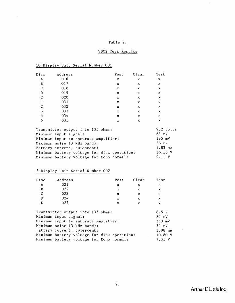
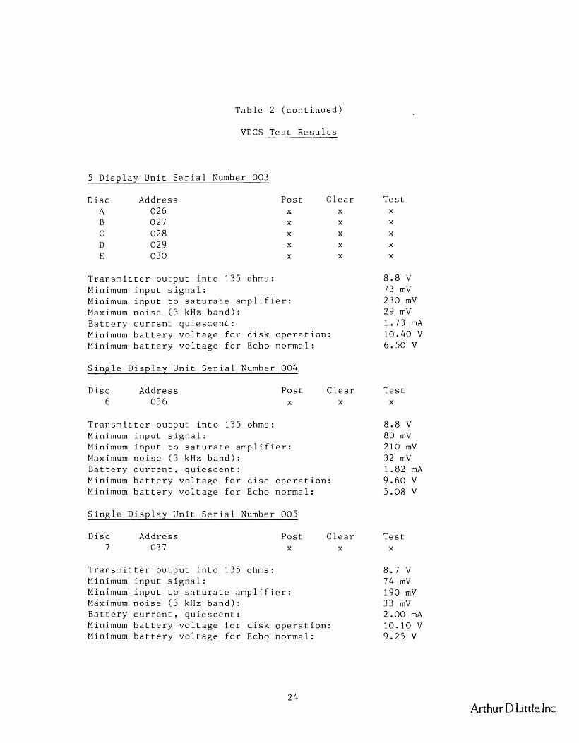
mine. Table 2 lists these results for all unit tests, together with
transmitter output voltage and function tests for each disk. Battery
current drain in the quiescent state was measured for each remote
unit, as were the battery voltages required for a normal echo return
and for proper disk operation.
The Monitor and Control Unit analog data channel was tested at several
voltages, with the results shown in Tables 2 and 3. Table 3 shows that
the A/D converter linearity is preserved within its 6-bit resolution.
Arthur DLittleInc
T a b l e 2.
VDCS T e s t R e s u l t s
10 D i s p l a y U n i t S e r i a l Number 0 0 1
D i s c Addres s 016 0 1 7 018 019 020 03 1 03 2 03 3 034 03 5
P o s t X
X
X
X
X
X
X
X
X
X
C l e a r X
X
X
X
X
X
X
X
X
X
T r a n s m i t t e r o u t p u t i n t o 135 ohms: Minimum i n p u t s i g n a l : Minimum i n p u t t o s a t u r a t e a m p l i f i e r : Maximum n o i s e ( 3 kHz b a n d ) : B a t t e r y c u r r e n t , q u i e s c e n t : Minimum b a t t e r y v o l t a g e f o r d i s k o p e r a t i o n : Minimum b a t t e r y v o l t a g e f o r Echo no rma l :
5 D i s ~ l a v U n i t S e r i a l Number 002
T e s t X
X
X
X
X
X
X
X
X
X
9.2 v o l t s 68 mV 195 mV 28 mV 1.83 mA 10.56 V 9.11 V
D i s c Addres s A 02 1 B 022 C 023 D 024 E 025
P o s t X
X
X
X
X
C l e a r T e s t X X
X X
X X
X X
X X
T r a n s m i t t e r o u t p u t i n t o 135 ohms: Minimum i n p u t s i g n a l : Minimum i n p u t t o s a t u r a t e a m p l i f i e r : Maximum n o i s e ( 3 kHz b a n d ) : B a t t e r y c u r r e n t , q u i e s c e n t : Minimum b a t t e r y v o l t a g e f o r d i s k o p e r a t i o n : Minimum b a t t e r y v o l t a g e f o r Echo no rma l :
Arthur DLittle,Inc
T a b l e 2 ( c o n t i n u e d )
VDCS T e s t R e s u l t s
5 D i s ~ l a v U n i t S e r i a l Number 003
D i s c A d d r e s s A 026 B 027 C 028 D 029 E 030
P o s t C l e a r T e s t X X X
X X X
X X X
X X X
X X X
T r a n s m i t t e r o u t p u t i n t o 135 ohms: 8 . 8 V Minimum i n p u t s i g n a l : 73 mV Minimum i n p u t t o s a t u r a t e a m p l i f i e r : 230 mV Maximum n o i s e ( 3 kHz b a n d ) : 29 mV B a t t e r y c u r r e n t q u i e s c e n t : 1 . 7 3 mA Minimum b a t t e r y v o l t a g e f o r d i s k o p e r a t i o n : 10 .40 V Minimum b a t t e r y v o l t a g e f o r Echo n o r m a l : 6 .50 V
S i n a l e D i s p l a y U n i t S e r i a l Number 004
D i s c A d d r e s s 6 03 6
P o s t C l e a r T e s t X X X
T r a n s m i t t e r o u t p u t i n t o 135 ohms: 8 . 8 V Minimum i n p u t s i g n a l : 8 0 mV Minimum i n p u t t o s a t u r a t e a m p l i f i e r : 210 mV Maximum n o i s e ( 3 kHz b a n d ) : 32 mV B a t t e r y c u r r e n t , q u i e s c e n t : 1 .82 mA Minimum b a t t e r y v o l t a g e f o r d i s c o p e r a t i o n : 9 . 6 0 V Minimum b a t t e r y v o l t a g e f o r Echo n o r m a l : 5 .08 V
S i n g l e D i s p l a y U n i t S e r i a l Number 005
D i s c Addre s s 7 03 7
P o s t C l e a r T e s t X X X
T r a n s m i t t e r o u t p u t i n t o 135 ohms: 8 . 7 V Minimum i n p u t s i g n a l : 74 mV Minimum i n p u t t o s a t u r a t e a m p l i f i e r : 190 mV Maximum n o i s e ( 3 kHz b a n d ) : 33 mV B a t t e r y c u r r e n t , q u i e s c e n t : 2 .00 mA Minimum b a t t e r y v o l t a g e f o r d i s k o p e r a t i o n : 10 .10 V Minimum b a t t e r y v o l t a g e f o r Echo n o r m a l : 9 .25 V
Arthur D Little, Inc.
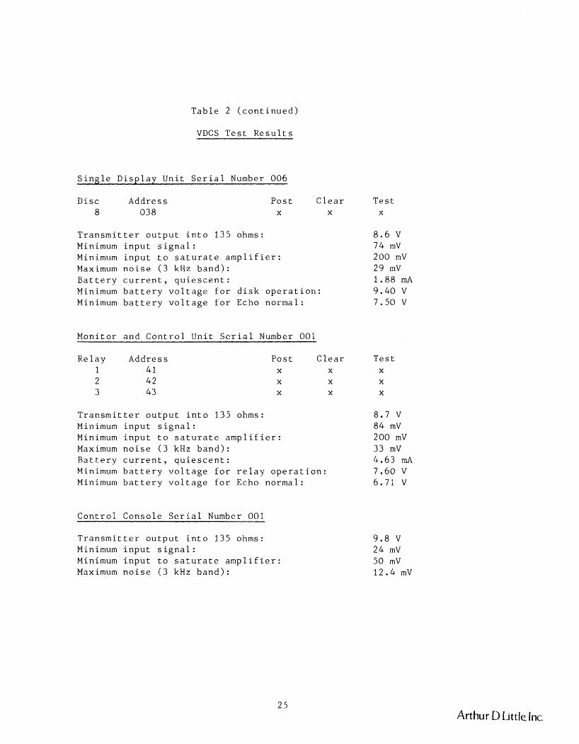
Table 2 (continued)
VDCS Test Results
Single Display Unit Serial Number 006
Disc Address 8 038
Post Clear X X
Transmitter output into 135 ohms: Minimum input signal: Minimum input to saturate amplifier: Maximum noise (3 kHz band): Battery current, quiescent: Minimum battery voltage for disk operation: Minimum battery voltage for Echo normal:
Monitor and Control Unit Serial Number 001
Relay Address 1 41 2 42 3 43
Post Clear X X
X X
X X
Transmitter output into 135 ohms: Minimum input signal: Minimum input to saturate amplifier: Maximum noise (3 kHz band): Battery current, quiescent: Minimum battery voltage for relay operation: Minimum battery voltage for Echo normal:
Control Console Serial Number 001
Transmitter output into 135 ohms: Minimum input signal: Minimum input to saturate amplifier: Maximum noise (3 kHz band):
Test X
Test X
X
X
Arthur D Little, lnc.
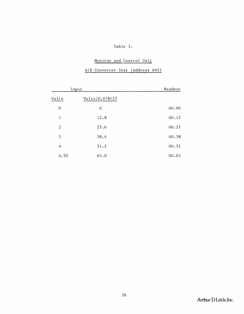
Table 3.
Monitor and Control Unit
AID Converter Test ( ~ d d r e s s 045)
Input Readout
Volts Volts/0.078125
Arthur D Little, Inc.
CONCLUSIONS
The Visual Display and Control System achieves the objective of a
mineworthy paging, monitor, and control system. Two aspects of system
performance should receive further attention: The noise immunity of
the receivers should be improved in order to permit operation to
maximum ranges in the noisiest mines, and the threshold battery
voltage for disk operation should be reduced so that the echo function
fails first. Both improvements are achievable by a modest amount of
redesign.
Arthur D Little, Inc.
INVENTIONS
There were no inventions made in conjunction with this contract.
Arthur D Little, Inc.