Embed Size (px)
Citation preview
Vision-Based Two-Factor Authentication &Localization Scheme for Autonomous Vehicles
Anas AlsolimanUniversity of California, Irvine
Marco LevoratoUniversity of California, Irvine
Qi Alfred ChenUniversity of California, Irvine
Abstract—In autonomous vehicle systems – whether groundor aerial – vehicles and infrastructure-level units communicateamong each other continually to ensure safe and efficient au-tonomous operations. However, different attack scenarios mightarise in such environments when a device in the networkcannot physically pinpoint the actual transmitter of a certainmessage. For example, a compromised or a malicious vehiclecould send a message with a fabricated location to appear as ifit is in the location of another legitimate vehicle, or fabricatemultiple messages with fake identities to alter the behavior ofother vehicles/infrastructure units and cause traffic congestion oraccidents. In this paper, we propose a Vision-Based Two-FactorAuthentication and Localization Scheme for Autonomous Vehi-cles. The scheme leverages the vehicles’ light sources and camerasto establish an “Optical Camera Communication (OCC)” channelproviding an auxiliary channel between vehicles to visuallyauthenticate and localize the transmitter of messages that are sentover Radio Frequency (RF) channels. Additionally, we identifypossible attacks against the proposed scheme as well as mitigationstrategies.
I. INTRODUCTION
Autonomous vehicles such as self-operated drones and carswill soon enable new applications in different domains, suchas autonomous transportation and drone delivery. However,safety-critical operations, such as object-detection and avoid-ance, are integral components of these applications and itwould make them appealing targets for cybercriminals [1]. Inthe United States, various efforts from government agencieshave been directed to set up the rules, regulations, and policiesfor managing the secure operations of future autonomoussystems (i.e., vehicles and Roadside Units, or RSUs). Forconnected and self-driving cars, the U.S. Department ofTransportation (USDOT) has adopted the Security CredentialManagement System (SCMS) [2] for handling secure vehicle-to-vehicle (V2V) and vehicle-to-infrastructure (V2I) commu-nications. For Unmanned Aerial Vehicles (UAVs), the FederalAviation Administration (FAA) and National Aeronautics andSpace Administration (NASA) have jointly developed the
Acknowledgement:This work was partially supported by CNS-1850533, CNS-1929771, andUSDOT UTC Grant 69A3552047138.This work was partially supported by the NSF grant IIS-1724331.
Network and Distributed Systems Security (NDSS) Symposium 2021 25 February 2021, Virtual ISBN 1-891562-68-1https://dx.doi.org/10.14722/autosec.2021.23021www.ndss-symposium.org
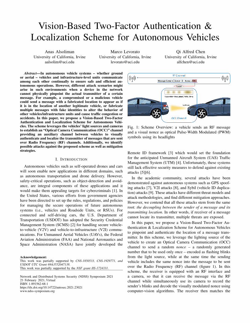
Fig. 1: Scheme Overview: a vehicle sends an RF messageand a visual nonce as optical Pulse-Width Modulated (PWM)symbols using its headlights
Remote ID framework [3] which would set the foundationfor the anticipated Unmanned Aircraft System (UAS) TrafficManagement System (UTM) [4]. Unfortunately, these systemsstill lack effective security measures to defend against existingattacks [5][6].
In the academic community, several attacks have beendemonstrated against autonomous systems such as GPS spoof-ing attacks [7], V2I attacks [8], and Sybil (vehicle ID duplica-tion) attacks [9]. These attacks have different threat models andattack methodologies, and find different mitigation approaches.However, we contend that all these attacks stem from the sameroot: the decoupling between the sender of a message and itstransmitting location. In other words, if receiver of a messagecannot locate its transmitter, multiple threats are exposed.
In this paper, we propose a Vision-Based Two-Factor Au-thentication & Localization Scheme for Autonomous Vehiclesto pinpoint and authenticate the location of a message trans-mitter. In this scheme, we leverage the lighting source of thevehicle to create an Optical Camera Communication (OCC)channel to send a random nonce – a randomly generatednumber that to be used only once – encoded as flashing blinksfrom the light source, while at the same time the sendingvehicle includes the same nonce into the message to be sentover the Radio Frequency (RF) channel (figure 1). In thisscheme, the receiver is equipped with an RF interface anda camera, so that it can receive the message via the RFchannel while simultaneously use its camera to record thesender’s blinks and decode the visually modulated nonce usingcomputer-vision algorithms. The receiver then matches the
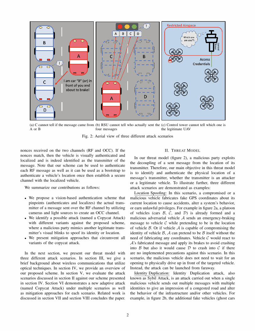
(a) C cannot tell if the message came fromA or B
(b) RSU cannot tell who actually sent thefour messages
(c) Control tower cannot tell which one isthe legitimate UAV
Fig. 2: Aerial view of three different attack scenarios
nonces received on the two channels (RF and OCC). If thenonces match, then the vehicle is visually authenticated andlocalized and is indeed identified as the transmitter of themessage. Note that our scheme can be used to authenticateeach RF message as well as it can be used as a bootstrap toauthenticate a vehicle’s location once then establish a securechannel with the localized vehicle.
We summarize our contributions as follows:
• We propose a vision-based authentication scheme thatpinpoints (authenticates and localizes) the actual trans-mitter of a message sent over the RF channel by utilizingcameras and light sources to create an OCC channel.
• We identify a possible attack (named a Copycat Attack)with different variants against the proposed scheme,where a malicious party mimics another legitimate trans-mitter’s visual blinks to spoof its identity or location.
• We present mitigation approaches that circumvent allvariants of the copycat attack.
In the next section, we present our threat model withthree different attack scenarios. In section III, we give abrief background about wireless communications that utilizeoptical techniques. In section IV, we provide an overview ofour proposed scheme. In section V, we evaluate the attackscenarios discussed in section II against our scheme presentedin section IV. Section VI demonstrates a new adaptive attack(named Copycat Attack) under multiple scenarios as wellas mitigation approaches for each scenario. Related work isdiscussed in section VII and section VIII concludes the paper.
II. THREAT MODEL
In our threat model (figure 2), a malicious party exploitsthe decoupling of a sent message from the location of itstransmitter. Therefore, our main objective in this threat modelis to identify and authenticate the physical location of amessage’s transmitter, whether the transmitter is an attackeror a legitimate vehicle. To illustrate further, three differentattack scenarios are demonstrated as examples:
Location Spoofing: In this scenario, a compromised or amalicious vehicle fabricates fake GPS coordinates about itscurrent location to cause accidents, alter a system’s behavior,or earn unlawful privileges. For example in figure 2a, a platoonof vehicles (cars B, C, and D) is already formed and amalicious adversarial vehicle A sends an emergency-brakingmessage to vehicle C while pretending to be in the locationof vehicle B. Or if vehicle A is capable of compromising theidentity of vehicle B, A can pretend to be B itself without theneed of fabricating any coordinates. Vehicle C would react toA’s fabricated message and apply its brakes to avoid crashinginto B but also it would cause D to crash into C if thereare no implemented precautions against this scenario. In thisscenario, the malicious vehicle does not need to wait for anopening to physically drive up in front of the targeted vehicle.Instead, the attack can be launched from faraway.
Identity Duplication: Identity Duplication attack, alsoknown as Sybil Attack, is an attack carried out when a singlemalicious vehicle sends out multiple messages with multipleidentities to give an impression of a congested road and alterthe behavior of the infrastructure and/or other vehicles. Forexample, in figure 2b, the additional fake vehicles (ghost cars
2
B, C, and D) generated by A would cause the traffic light toturn green sooner in the attacker’s lane and longer for otherlanes in order to clear the congested lane.
Identity Confusion: In this scenario (figure 2c), a swarmof unmanned aerial vehicles (UAVs) are flying in close-proximity of each other. A legitimate UAV is supplementingits credentials to the control tower for accessing the nearbyrestricted airspace. During that time, another intruding UAVenters the restricted airspace. Here the control tower cannotenforce the given access (e.g., take down the intruding UAV)since it cannot physically differentiate between the legitimateand the intruding UAV.
We can observe that each scenario represents differentattacking capabilities. In the first scenario, the attacker has theability to either fabricate the content of its messages or use theidentity of another legitimate vehicle. In the second scenario,the attacker has the ability to generate multiple identitiesof non-existing vehicles. In the third scenario, the attackeris able to passively listen to messages in order to make anopportunistic attack (e.g. invasive access towards a restrictedairspace). However, all three scenarios can be exploited dueto the same reason; the inability of the receiver to localize thetransmitter of the messages.
III. BACKGROUND ON OPTICAL WIRELESSCOMMUNICATION
A. Overview
Optical Wireless Communication (OWC) is any communi-cation channel that utilizes the terahertz band of the electro-magnetic spectrum which includes the infrared and ultravio-let frequencies. Furthermore, an OWC channel utilizing thevisible-light portion of the terahertz band is referred to asVisible Light Communication (VLC).
Optical communications require an imaging sensor for re-ceiving the incoming light photons. That sensor is commonlyknown as a photodetector. A camera sensor such as Comple-mentary Metal Oxide Semiconductor (CMOS) consists of amatrix of photodetectors, each represents a pixel which gets itscolor by measuring the intensity and frequency of the recordedphoton by its corresponding photodetector. The main objectiveof a camera sensor is to create an image out of the CMOSoutput as a grid of colored pixels, and the rate of imagescreated by the sensor is known as frame per second (FPS).However, since cameras have become a commodity hardware,their sensors have been repurposed for various applicationssuch as decoding messages that are digitally modulated intoimages. This type of optical communication technique iscommonly known as Optical Camera Communication (OCC).
B. OCC Channel Model
Our channel model is based on two assumptions: (i) Themodulation scheme used over the OCC channel is assumedto be optical On-Off Keying (OOK) since it only requires asingle narrowband frequency (i.e., single color) which makesit applicable to any light sources. Note that visual symbolsin figure 1 and 3 are pulse-width modulated (PWM) for ease
of illustration only. (ii) We assumes the use of cameras thatare operated using the global shutter mode where all camerapixels are scanned simultaneously. The rolling shutter mode(its counterpart) scans rows of pixel independently one afteranother. However, the security intuitions in this paper stillholds true for both assumptions and should be applicable todifferent imaging techniques.
In OCC systems, a communication channel using OOKmodulation can be modeled as a rectangular waveform. LetTe denote to the camera exposure time which defines howlong a camera shutter stays open to capture a single frame.Therefore, Te is the inverse of the camera sampling rate FPSsuch that Te = 1
FPS . Let PWs denote the symbol pulse-width which defines how long a light source stays on duringthe Te time frame. Intuitively, we have PWs < Te. However,there is a minimum duty cycle DCmin = PWs
Tefor a given
OCC system under certain conditions and SINR requirements.Furthermore, a guard width PWg must be left unoccupied atthe beginning and the end of the Te time frame to prevent sym-bols from leaking into adjacent frames (similar to the guardbands that are added between RF channels to prevent inter-symbol interference). Finally, in our scheme, the OCC can bemodeled as PWs + PWg < Te for PWs ≥ DCmin × Te.Note that the propagation delay is omitted from the channelmodel since it has a negligible effect especially for close-rangecommunications such as in V2V and V2I. Furthermore, theguard band PWg should mitigate the effects of propagationdelay whenever it becomes critically high.
C. Challenges
There are several challenges when working with OCCsystems such as: (i) unidirectional link - a lighting sourcecan only be used for transmitting while a camera is only forreceiving, (ii) highly directional communications - the cameraand the lighting source need to face each other in a clearline-of-sight (LOS), and (iii) low bitrate - common camerasensors can sample up to 30 FPS (stand-alone photodetectorsare capable of higher sampling rates with more complexmodulation schemes, but cannot construct an image out ofthe received photons).
The requirements of our scheme are not affected by theseshortcomings. For instance, the receiver in our scheme doesnot require a feedback channel for locating the sender, andwhenever a feedback is required (e.g. loss in clock synchro-nization) the RF channel can be used. Also based on the threatmodel discussed in Section II, the sender is expected to bein a clear view of the receiver which means that clear LOSis an inherent requirement for all the three attack scenariosexplained in Section II. Concerning the bitrate, the senderencodes only a short nonce into the OCC channel whereasthe main message is sent over the RF channel. Therefore,a low OCC bitrate is sufficient to execute the authenticationscheme. Furthermore, lower bitrates can be modulated usinglonger symbol periods which inherently make it cover largerdistances in the optical domain.
3
IV. SCHEME OVERVIEW
As discussed in section I, our scheme utilizes two differentcommunication channels, an RF channel and an OCC channel.Both the sender and the receiver are equipped with an RFinterface to implement an RF channel while the OCC channelrequires the sender to be equipped with lighting source such asa light-emitting diode (LED), and the receiver to be equippedwith a camera. We assume that these equipment are alreadyavailable in most autonomous vehicles since we expect modernautonomous systems to have the minimum set of requirementsto carry out safe and secure autonomous operations, whichinclude: an RF interface (for wireless communications), acamera (for object detection and navigation), and a lightingsource (for safety, illumination, and identification purposes)such as car’s headlights/taillights and drone’s anti-collisionstrobe lights.
Authentication & Localization Process: When a sendertransmits a message over the RF channel, it includes a noncein the message, while at the same time it encodes the samenonce as modulated blinks into the OCC channel using its lightsource. On the other hand, the receiver will continuously scanevery captured camera frame for possible OOK modulatedsymbols. Here the receiver employs computer-vision algo-rithms and look at every two consecutive frames for a suddenchange in pixel intensity. When a pixel intensity change isfound, the algorithm locks on the object emitting the lightsource that caused the intensity change and extract the symbolsencoded into each subsequent frame. The area of the lockedobject is called Region of Interest (ROI). Now whenever thereceiver receives a message over the RF channel, it cross-references its nonce with the demodulated nonces emittedby the current ROI over the OCC channel at the time ofmessage reception. To illustrate, to transmit biti = ”1” asan OOK modulated symbol, the sender sets its light sourceon high for PWs seconds during the camera exposure timeframe Tei . To transmit the next biti+1 = ”0”, the sendersets its light source to off-state during the next transmissionwindow Tei+1 . The receiver would detect a transition periodfrom Tei to Tei+1
time frames as a change in pixel intensitycaused by biti and biti+1 respectively. As a result, the receiverwill lock on the ROI region of the captured picture thathas a pixel intensity change. This process will be triggeredfrom the very first transmitted bit1 where a timer TOCC
will be set starting from the beginning of Te1 . When thereceiver receives a message from the RF channel that has thesame nonce which is received from the OCC channel, thetime difference between the two messages must satisfy thefollowing condition: |TOCC − TRF | < θ where TRF denoteto the time where the first bit of the message was receivedover the RF channel and θ denote to a minimum thresholdthat can be used as an attack window. More details on theaforementioned attack will be discussed in Section VI-A.
Technical Considerations: To prevent accidental ROI locksthat are caused by pixel intensity change due to randomenvironmental factors (such as a vehicle turning on its head-
lights or an object moving in front of a light source whichwould be interpreted as an OOK modulated symbol), OCCsystems would use a preamble with an alternating 0s and 1s tosynchronize the sender with the receiver before locking on theROI and recording the nonce. Another point to consider is thatduring an OCC transmission, the nonce encoded by the sendermight include long runs of 0s or 1s (continuous repetitions of0s or 1s) which would cause multiple consecutive frames tonot have any intensity change across their transitions whichin turn cause a loss in clock synchronization on receiver side(cannot distinguish whether the transmission has ended or along run is being transmitted). Therefore, the sender woulduse Run Length Limited (RLL) codes such as Manchesterencoding where a ”1” is represented as ”01” and ”0” isrepresented as ”10”. In this case, the receiver would have atmost two consecutive frames with the same modulated symbol(maximum possible run is two frames). Finally, the change inOCC channel state (i.e. blinking) should be faster than theperception of the human eye to prevent causing confusions tosurrounding human drivers/pedestrians and also physiologicaleffects such as nausea. The IEEE 802.15.7 standard [10] forShort-Range Optical Wireless Communications recommendsthe use of at least 200 Hz in light flickering frequency.
V. SCHEME DEFENSE ANALYSIS
In this section, we evaluate our scheme (section IV) againstthe threat model (section II).
Scenario A: in figure 2a, the malicious vehicle A attemptsto deceive vehicle C by pretending to be vehicle B or byfabricating its location to appear as if A is in front of C.With our scheme, whenever C receives a message pretendingto be from B, it checks the message’s nonce with the visualnonce emitted by B which is physically in front of C. If thetwo nonces from the two channels (RF and OCC) match, themessage is indeed from B. Otherwise, the message will beflagged as a spoofing attempt.
Scenario B: in figure 2b, the malicious vehicle attempts todeceive the traffic light into believing that the lane is crowdedby broadcasting multiple messages with different IDs. Here thetraffic light will use the OCC channel to match each messagewith its sender. Since the attacker is the sender of all themessages, all message IDs will be mapped to the same vehiclewhich will trigger a spoofing attempt.
Scenario C: in figure 2c, a malicious unmanned aerialvehicle (UAV) attempts to access a restricted airspace byopportunistically waiting for a legitimate UAV to present itsaccess credentials to the control tower. When the credentialsare broadcasted, the malicious UAV flies to the restrictedairspace knowing that the control tower cannot physicallydistinguish between the legitimate UAV from the maliciousone. With our scheme, the legitimate UAV can physicallypresent itself using OCC channel to distinguish itself fromall other nearby UAVs.
VI. COPYCAT ATTACK & MITIGATION METHODS
The threat model presented in section II represents threedifferent attack scenarios that an attacker might attempt under
4
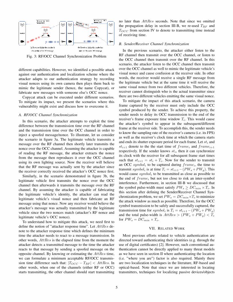
Fig. 3: RF/OCC Channel Synchronization Problem
different capabilities. However, we identified a possible attackagainst our authentication and localization scheme where theattacker adapts to our authentication strategy by recordingvisual nonces using its own camera then plays them back tomimic the legitimate sender (hence, the name Copycat), orfabricate new messages with someone else’s OCC nonce.
Copycat attack can be executed under different scenarios.To mitigate its impact, we present the scenarios where thisvulnerability might exist and discuss how to overcome it.
A. RF/OCC Channel Synchronization
In this scenario, the attacker attempts to exploit the timedifference between the transmission time over the RF channeland the transmission time over the OCC channel in order toinject a spoofed message/nonce. To illustrate, let us considerthe scenario in figure 3a. The legitimate vehicle transmits amessage over the RF channel then shortly later transmits thenonce over the OCC channel. Assuming the attacker is capableof reading the RF message, the attacker extracts the noncefrom the message then reproduces it over the OCC channelusing its own lighting source. Now the receiver will believethat the RF message was actually sent by the attacker sincethe receiver correctly received the attacker’s OCC nonce first.
Similarly, in the scenario demonstrated in figure 3b, thelegitimate vehicle first transmits the nonce over the OCCchannel then afterwards it transmits the message over the RFchannel. By assuming the attacker is capable of fabricatingthe legitimate vehicle’s identity, the attacker can read thelegitimate vehicle’s visual nonce and then fabricate an RFmessage using that nonce. Now any receiver would believe theattacker’s message was actually transmitted by the legitimatevehicle since the two nonces match (attacker’s RF nonce andlegitimate vehicle’s OCC nonce).
To understand how to mitigate this attack, we need first todefine the notion of ”attacker response time”. Let AttRes de-note to the attacker response time which defines the minimumtime the attacker needs to react to a message transmission. Inother words, AttRes is the elapsed time from the moment theattacker detects a transmitted message to the time the attackerreacts to that message by sending a spoofed message on theopposite channel. By knowing or estimating the AttRes time,we can formulate a minimum acceptable RF/OCC transmis-sion time difference such that: |TOCC − TRF | < AttRes. Inother words, when one of the channels (either RF or OCC)starts transmitting, the other channel should start transmitting
no later than AttRes seconds. Note that since we omittedthe propagation delay in section III-B, we re-used TRF andTOCC from section IV to denote to transmitting time insteadof receiving time.
B. Sender/Receiver Channel Synchronization
In the previous scenario, the attacker either listen to theRF channel then transmit over the OCC channel, or listen tothe OCC channel then transmit over the RF channel. In thisscenario, the attacker listen to the OCC channel then transmitover the OCC channel as well to mimic the legitimate vehicle’svisual nonce and cause confusion at the receiver side. In otherwords, the receiver would receive a single RF message fromthe legitimate vehicle but at the same time it will receive thesame visual nonce from two different vehicles. Therefore, thereceiver cannot distinguish who is the actual transmitter sincethere are two different vehicles emitting the same visual nonce.
To mitigate the impact of this attack scenario, the cameraframe captured by the receiver must only include the OCCsymbol produced by the sender. To achieve this property, thesender needs to delay its OCC transmission to the end of thereceiver’s frame exposure time window Te. This would causethe attacker’s symbol to appear in the subsequent/differentframe at the receiver side. To accomplish this, the sender needsto know the sampling rate of the receiver’s camera (i.e. its FPS)as well as the receiver’s clock time at which the camera startsand ends its shutter exposure period for each frame. Let sti andsti+1 denote to the the start time of framei and framei+1
respectively. If the sender knows sti, then it can synchronizeits clock with the receiver for all subsequent frame start timessuch that sti+1 = sti + Te. Now for the sender to transmitan OCC symboli to be captured during framei, the time totransmit symboli is at time Ti = sti+1−(PWs+PWg). Thiswould cause symboli to be transmitted as close as possible tothe end of framei but not too close to risk an inter-symbolinterference. Furthermore, in section III-B we discussed thatthe symbol pulse-width must satisfy PWs ≥ DCmin×Te. Inthis section after defining the Sender/Receiver Channel Syn-chronization problem, we set PWs = DCmin×Te to minimizethe attack window as much as possible. Therefore, for the OCCsymbol transmission to be safely and successfully captured, thetransmission time for symboli is Ti = sti+1− (PWs+PWg)and the total pulse-width is AttRes > (PWs + PWg) < Tefor PWs = DCmin × Te.
VII. RELATED WORK
Most previous efforts related to vehicle authentication aredirected toward authenticating their identities (e.g. through theuse of digital certificates) [2]. However, such conventional au-thentication cannot be directly applied to many threat modelsas we have seen in section II where authenticating the location(i.e. ”where you are”) factor is also required. Mainly thereare two localization techniques in the literature, RF-based andoptical-based. Note that since we are interested in locatingtransmitters, techniques for localizing passive devices/objects
5
such as computer-vision object detection and radar will not bediscussed.
RF-Based Localization has abundant number publications.It mainly relies on Time/Difference of Arrival (ToA/TDoA),Angle of Arrival (AoA) and RSSI measurements techniques.For example [9] proposed an RSSI-based localization algo-rithm that depends on vehicles or RSUs as observers totriangulate the target vehicle. However, the dependence onother trusted vehicles sets a limitation to the threat model.Furthermore, the location of a target vehicle is approximated asan area (a common limitation for most RF-based localizationschemes). That means a group of vehicles in close-proximitywith each other (a typical road scenario) would have verysimilar RF transmissions in terms of timing and angle whichmakes it a challenging task to localize one of the vehiclesamong the other group members. Even a single attacker canmanipulate its transmission power and timing to deviate theobservers. In general, RF-based localization schemes tend tobe complex, require special antenna designs, and suffer frommultipath and interference phenomena [11].
Vision-Based Localization is a well studied research fieldbut mostly in the context of using visual cues as beaconsfor enabling devices to localize themselves. For example,[11] uses projectors and photodetectors while [12] uses LEDsand cameras as indoor localization solutions. However, suchsolutions cannot be repurposed to our threat model sinceit either require the cooperation of the localized device orrequire a map reconstruction phase (also found in RF-basedtechniques) prior to rolling out the localization system. Invehicle network, the use of VLC channels is gaining a greatattention lately but mainly in the context of communicationrather than localization which might make it inapplicable toour threat model. For example to increase the bitrate of theVLC channel, [13] sampled each row of a rolling shutterindependently while [14] suggested the use of a standalonephotodiode but both techniques make it impossible (or at leastextremely difficult) to construct an image from the receivedVLC signal. [15] and [16] attempted to increase the VLCbitrate with a fully constructed image by utilizing visual-MIMO (Multiple Input Multiple Output) where multiple lightsources act as multiple output and the individual pixels of thereceiver’s camera are considered the multiple inputs. However,visual-MIMO via OCC requires additional hardware and its biterror rate drastically increases with increased distances [17]. Inan alternative approach, [18] implemented a visual localizationscheme for drone swarms where a locator commands the targetdrone that need to be localized to perform a short flight ma-neuver such as a quick turn which would act as a visual cue forthe locator who is equipped with a camera to distinguish thetarget drone among the other swarm members. However, themaneuver command cannot be performed until a safe distancefrom all surrounding objects is established. Furthermore, itis difficult for stationary vehicles to perform maneuvers suchas cars stopped at a red light. Finally, accepting maneuverrequests from other devices adds an additional attack surfaceto the autonomous system.
VIII. CONCLUSION & FUTURE WORK
We proposed a vision-based authentication and localizationscheme for autonomous vehicles that employ localization as aform of authentication where we use visual nonces as a proofof RF message transmission. We also introduced a CopycatAttack that exploits our scheme’s synchronization vulnerabili-ties as well as mitigation approaches for each vulnerability. Infuture work, we will design testbed to (i) numerically defineAttRes and PWg then evaluate if AttRes > (DCmin×Te)+PWg can be applied using commodity cameras with an accept-able SINR, (ii) implement an encoding scheme that utilizes alow frame rate (e.g. 30FPS) as a receiver and high flickeringfrequency (e.g. 200Hz) as a transmitter without introducingthe sender/receiver sync problem, and (iii) demonstrate a dual-channel protocol that sync between the low bitrate of the OCCchannel and high bitrate of the RF channel without introducingthe OCC/RF sync problem.
REFERENCES
[1] Y. Cao et al., “Adversarial sensor attack on lidar-based perceptionin autonomous driving,” in Proceedings of the 2019 ACM SIGSACConference on Computer and Communications Security, 2019.
[2] USDOT, Security Credential Management System (SCMS), 2021 (ac-cessed January 5, 2020). https://www.its.dot.gov/resources/scms.htm.
[3] FAA, UAS Remote Identification, 2021 (accessed January 5, 2020).https://www.faa.gov/uas/researchdevelopment/remoteid/.
[4] FAA, Unmanned Aircraft System Traffic Manage-ment (UTM)’, 2021 (accessed January 5, 2020).https://www.faa.gov/uas/researchdevelopment/trafficmanagement/.
[5] M. D. Furtado et al., “Threat analysis of the security credential manage-ment system for vehicular communications,” in 2018 IEEE InternationalSymposium on Technologies for Homeland Security (HST), IEEE, 2018.
[6] A. Alsoliman et al., “Privacy-preserving authentication framework foruas traffic management systems,” in 2020 4th Cyber Security in Net-working Conference (CSNet), pp. 1–8, IEEE, 2020.
[7] X. Huang et al., “Exposing spoofing attack on flocking-based unmannedaerial vehicle cluster: A threat to swarm intelligence,” Security andCommunication Networks, vol. 2020, 2020.
[8] S. E. Huang et al., “Impact evaluation of falsified data attackson connected vehicle based traffic signal control,” arXiv preprintarXiv:2010.04753, 2020.
[9] M. T. Garip et al., “Interloc: An interference-aware rssi-based local-ization and sybil attack detection mechanism for vehicular ad hocnetworks,” in 2017 14th IEEE Annual Consumer Communications &Networking Conference (CCNC), pp. 1–6, IEEE, 2017.
[10] IEEE Standard for Local and metropolitan area networks. IEEE802.15.7-2018.
[11] S. Ma et al., “Foglight: Visible light-enabled indoor localization systemfor low-power iot devices,” IEEE Internet of Things Journal, vol. 5,no. 1, pp. 175–185, 2017.
[12] P. Chavez-Burbano et al., “Optical camera communication system forthree-dimensional indoor localization,” Optik, vol. 192, p. 162870, 2019.
[13] T. Nguyen et al., “High-speed asynchronous optical camera communica-tion using led and rolling shutter camera,” in 2015 Seventh InternationalConference on Ubiquitous and Future Networks, IEEE, 2015.
[14] P. H. Pathak et al., “Visible light communication, networking, andsensing: A survey, potential and challenges,” IEEE communicationssurveys & tutorials, vol. 17, no. 4, pp. 2047–2077, 2015.
[15] J.-E. Kim et al., “Color-space-based visual-mimo for v2x communica-tion,” sensors, vol. 16, no. 4, p. 591, 2016.
[16] W. Yuan et al., “Computer vision methods for visual mimo opticalsystem,” in CVPR 2011 workshops, pp. 37–43, IEEE, 2011.
[17] N. T. Le et al., “A survey of design and implementation for opticalcamera communication,” Signal Processing: Image Communication,vol. 53, pp. 95–109, 2017.
[18] C. Ruiz et al., “Idrone: Robust drone identification through motionactuation feedback,” Proceedings of the ACM on Interactive, Mobile,Wearable and Ubiquitous Technologies, vol. 2, no. 2, pp. 1–22, 2018.
6