Embed Size (px)
Citation preview
The 14th IFToMM World Congress, Taipei, Taiwan, October 25-30, 2015 DOI Number: 10.6567/IFToMM.14TH.WC.OS13.117
Vision-based Automated Guided Vehicle Control by
Using Fuzzy Kohonen Clustering Network
Meng-Ju Han1 and Jie-Ming Wang2
Mechanical and Systems Research Laboratories, Industrial Technology Research Institute
Hsinch, Taiwan
Abstract: Automated guided vehicle (AGV) is widely used in
the industrial field. Most existing methods treat the AGV
controller by simple and intuitive representations such like PID
controller. However, the PID controller lacks a standard
procedure to generate proper parameters and let suitable
parameters adjusting become a heuristic work. This paper
presents a vision-based control method for mobile platform.
Three modules are integrated to construct the control system,
namely, color path detection module, path feature extraction
module and control behavior decision maker. Based on Fuzzy
Kohonen clustering network, a fuzzy concept control system is
proposed to build a standard procedure. All parameters of the
controller are self-generated without relying on human’s
experience. Experimental results show that the proposed vision-
based guiding scheme appropriately responds to varies color
path in a continuous manner.
Keywords: Vision-based guiding, Fuzzy Kohonen clustering
network, Automated guided vehicle
1 Introduction
In past years, the automated guided vehicle (AGV) is
widely used in the industrial field because AGVs are the
most well-known robot in manufacturing environments. In
addition, AGV has broadened during recent years to
include advanced robotics technology that is no longer
restricted to the industrial environment. More recent AGV
applications include use in the healthcare, military, and
transportation logistics markets. Methodologies for AGV
guidance have drawn much attention in automation
community. The most of used type is to detect the
magnetic tape and follow the corresponding path. Also,
laser, sonar, infrared and radio-frequency (RF) sensors are
used for the vehicle guidance [1, 2]. Although above
mentioned sensors are good for using in the factory, the
concerns of more intelligent and lower price are still the
issues for further study.
The vision-guided method is developed rapidly on
AGV navigation in recent years. Butdee et al. [3]
proposed the methodology for solving the problem of path
discontinuity. In their design, Laplacian operator and
trigonometry method are combined for edge detection and
path discontinuous estimation. Park et al. [4] presented a
guiding method of the port AGV, especially parking
system. The proposed algorithm locates the vehicle into a
specific position with appropriate error rates using vision-
based methods that detect and track the visual object in
the video streams. Quan et al. [5] adopted fuzzy control
technology to direction change of steering engine, and
realized smart car’s direction control flexibly and
intelligently. For the problem of the path tracking with
[email protected]; [email protected]
nonholonomic constrains characteristics, Jingtian et al. [6]
designed a predictive controller based on global gradient
descent algorithm. A set of initial control sequence is
generated based on the principle of gradient descent to
solve the affection of various constraints.
Previous related works show abundant powerful tools
for designing vision-guided AGV. It is observed that a
proper control behavior decision plays an important role
in direction angle. However, most existing method treat
control behavior decisions by simple and intuitive
representations such like PID (proportional, integral and
derivative) controller. The controller lacks a standard
procedure to generate proper parameter and let adjusting
suitable parameter become a heuristic work. In this study,
a fuzzy concept system is proposed to build a standard
procedure. All parameters of the controller are self-
generated without relying on human’s experience.
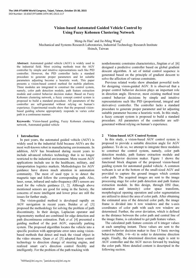
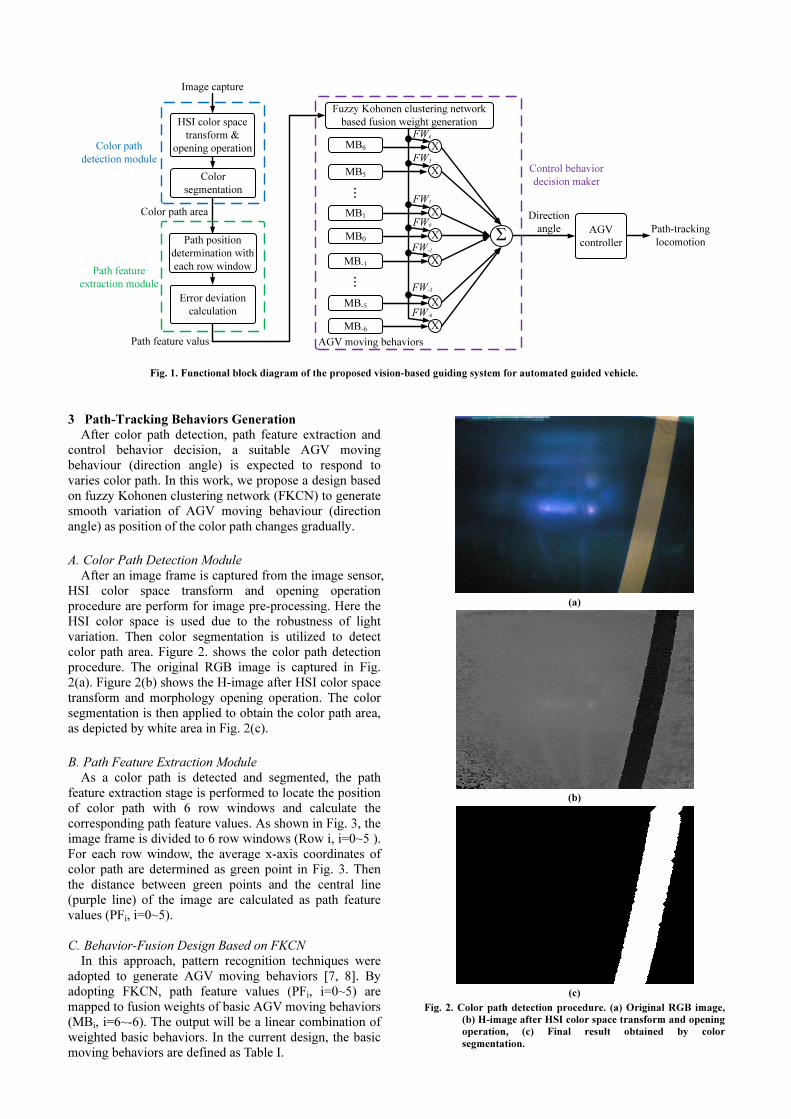
2 Vision-based AGV Control System
In this study, a vision-based AGV control system is
proposed to provide a suitable direction angle for AGV
guidance. To do so, we attempt to integrate three modules
to construct the control system, namely, color path
detection module, path feature extraction module and
control behavior decision maker. Figure 1 shows the
functional block diagram of the proposed vision-based
guiding system for automated guided vehicle. A common
webcam is set at the bottom of the small-sized AGV and
provided to capture the ground images which contain
color path. The acquired images are sent to the image
processing stage for color path detection and path feature
extraction module. In this design, through HSI (hue,
saturation and intensity) color space transform,
morphological opening operation and color segmentation
are utilized to detect the area of color path. After obtaining
the estimated area of the detected color path, the image
frame is divided into 6 row windows and the x-axis
coordinates of color path with each row window are
determined. Further, the error deviation, which is defined
as the distance between the color path and central line of
the image frame, is calculated to get path feature values.
The calculated path feature consists of 6 integer values
at each sampling instant. These values are sent to the
control behavior decision maker to fuse 13 basic moving
behaviors (MBi, i=6~-6) in order to determine direction
angle. Finally, the determined direction angle is sent to
AGV controller and the AGV moves forward by tracking
the color path. More detailed content is descripted in the
following section.
3 Path-Tracking Behaviors Generation
After color path detection, path feature extraction and
control behavior decision, a suitable AGV moving
behaviour (direction angle) is expected to respond to
varies color path. In this work, we propose a design based
on fuzzy Kohonen clustering network (FKCN) to generate
smooth variation of AGV moving behaviour (direction
angle) as position of the color path changes gradually.
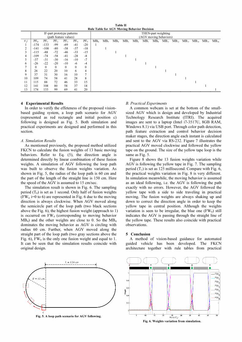
A. Color Path Detection Module
After an image frame is captured from the image sensor,
HSI color space transform and opening operation
procedure are perform for image pre-processing. Here the
HSI color space is used due to the robustness of light
variation. Then color segmentation is utilized to detect
color path area. Figure 2. shows the color path detection
procedure. The original RGB image is captured in Fig.
2(a). Figure 2(b) shows the H-image after HSI color space
transform and morphology opening operation. The color
segmentation is then applied to obtain the color path area,
as depicted by white area in Fig. 2(c).
B. Path Feature Extraction Module
As a color path is detected and segmented, the path
feature extraction stage is performed to locate the position
of color path with 6 row windows and calculate the
corresponding path feature values. As shown in Fig. 3, the
image frame is divided to 6 row windows (Row i, i=0~5 ).
For each row window, the average x-axis coordinates of
color path are determined as green point in Fig. 3. Then
the distance between green points and the central line
(purple line) of the image are calculated as path feature
values (PFi, i=0~5).
C. Behavior-Fusion Design Based on FKCN
In this approach, pattern recognition techniques were
adopted to generate AGV moving behaviors [7, 8]. By
adopting FKCN, path feature values (PFi, i=0~5) are
mapped to fusion weights of basic AGV moving behaviors
(MBi, i=6~-6). The output will be a linear combination of
weighted basic behaviors. In the current design, the basic
moving behaviors are defined as Table I.
(a)
(b)
(c)
Fig. 2. Color path detection procedure. (a) Original RGB image,
(b) H-image after HSI color space transform and opening
operation, (c) Final result obtained by color
segmentation.
HSI color space
transform &
opening operation MB6
AGV moving behaviors
AGV
controller
Path-tracking
locomotionΣ
FW6
Direction
angle
Fuzzy Kohonen clustering network
based fusion weight generation
Color path
detection moduleControl behavior
decision maker
XFW5
X
FW1
XFW0
XFW-1
X
FW-5
XFW-6
X
Color
segmentation
MB5
MB1
MB0
MB-1
MB-5
MB-6
Image capture
Path position
determination with
each row window
Error deviation
calculation
Path feature
extraction module
...
...
Color path area
Path feature valus
Fig. 1. Functional block diagram of the proposed vision-based guiding system for automated guided vehicle.

FKCN is employed to determine the fusion weight of
each basic AGV moving behavior based on the current
path feature values. Figure 4 illustrates the structure of the
fuzzy-neuro network for fusion weight generation. In the
input layer of the network, the path feature values are
regarded as inputs of FKCN. In the distance layer, the
distance between input pattern and each prototype pattern
is calculated such that:
( ) ( )ji
T
jijiij PXPXPXd −−=−=2
(1)
where Xi denotes the input pattern and Pj denotes the jth
prototype pattern. In this layer, the degree of difference
between the current path feature value and the prototype
pattern is calculated. If the path feature value is not similar
to the build-in prototype patterns, then the distance will
reflect the dissimilarity. The membership layer is provided
to map the distance dij to membership values uij, it
calculates the similarity degree between the input pattern
and the prototype patterns. If an input pattern does not
match any prototype pattern, then the similarity between
the input pattern and each individual prototype pattern is
represented by a membership value from 0 to 1. The
determination of the membership value is given such that:
( )⎩⎨⎧
−≤>==
=1,000
01
cjkdif
difu
ik
ij
ij (2)
where c denotes the number of prototype patterns,
otherwise,
11
0
−−
=⎥⎦
⎤⎢⎣
⎡= ∑
c
l il
ij
ijd
du (3)
Note that the sum of the outputs of the membership layer
equals 1. Using the rule table (see later) and the obtained
membership values, the current fusion weights (FWi,
i=0~12) are determined such that:
∑−
=
=1
0
c
j
ijjiiuwFW (4)
where wji represents the prototype-pattern weight of ith
output behavior. The prototype-pattern weights are
designed in a rule table to define basic AGV moving
behaviors corresponding to carefully chosen input path
feature values.
D. The Rule Table
In the current design, a rule table is constructed
accordingly following the structure of FKCN. As shown
in Table II, 13 basic AGV moving behaviors were
selected to build the rule table. The IF-part of the rule
table is the path feature values and the Then-part is the
prototype-pattern weight (wji) of 13 basic AGV moving
behaviors. For example, the 13th moving behavior (MB13)
in Fig. 3 occurs at (174, 133, 99, 69, 41, 20); which forms
the IF-part of the 13th rule and the prototype pattern for
13th behavior. The THEN-part of this rule is the 13th
behavior or expressed by a vector of prototype-pattern
weights (0, 0, 0, 0, 0, 0, 0, 0, 0, 0, 0, 0, 1). The other rules
and prototype patterns are set up similarly following
practical experiments. There are all together 13 rules as
shown in Table II. FKCN works to generalize from these
prototype patterns to all possible situations (path feature
values in this case) that may happen to the AGV. In the
FKCN generalization process, proper fusion weights for
the corresponding pattern are calculated. After obtaining
the fusion weights of output behaviors from FKCN, the
direction angle of AGV is determined from 13 basic
moving behaviors weighted by their corresponding fusion
weights such that:
∑−
=×=
6
6i
iiFWMBAngleDirection (5)
Row 0
Row 1
Row 2
Row 3
Row 4
Row 5
PF0=174
PF1=133
PF2= 99
PF3= 69
PF4= 41
PF5= 20
Central line of image PF0
Extracted feature
point
Fig. 3. Test results of path feature extraction and corresponding
feature values calculation.
Table I
Definition of Basic AGV Moving Behaviors
Moving behavior Definition
MB6 Turn counterclockwise to 40 cm radius. MB5 Turn counterclockwise to 47 cm radius. MB4 Turn counterclockwise to 61 cm radius. MB3 Turn counterclockwise to 80 cm radius. MB2 Turn counterclockwise to 110 cm radius.MB1 Turn counterclockwise to 210 cm radius.MB0 Move straight forward. MB-1 Turn clockwise to 210 cm radius. MB-2 Turn clockwise to 110 cm radius. MB-3 Turn clockwise to 80 cm radius. MB-4 Turn clockwise to 61 cm radius. MB-5 Turn clockwise to 47 cm radius. MB-6 Turn clockwise to 40 cm radius.
AG
V m
ov
ing
beh
avio
r
estimato
r
...
...
⎥⎥⎥⎥⎥⎥⎥⎥
⎦
⎤
⎢⎢⎢⎢⎢⎢⎢⎢
⎣
⎡
=
5
4
3
2
1
0
PF
PF
PF
PF
PF
PF
iX
⎥⎥⎥⎥⎥⎥
⎦
⎤
⎢⎢⎢⎢⎢⎢
⎣
⎡
−
−
6
5
5
6
FW
FW
FW
FW
M
Fig. 4. The fuzzy-neuro network for fusion weight generation.
4 Experimental Results
In order to verify the effeteness of the proposed vision-
based guiding system, a loop path scenario for AGV
(represented as red rectangle and initial position c)
following is designed as Fig. 5. Both simulation and
practical experiments are designed and performed in this
section.
A. Simulation Results
As mentioned previously, the proposed method utilized
FKCN to calculate the fusion weights of 13 basic moving
behaviors. Refer to Eq. (5), the direction angle is
determined directly by linear combination of these fusion
weights. A simulation of AGV following the loop path
was built to observe the fusion weights variation. As
shown in Fig. 5, the radius of the loop path is 60 cm and
the part of the length of the straight line is 150 cm. Here
the speed of the AGV is assumed to 15 cm/sec.
The simulation result is shown in Fig. 6. The sampling
period (T0) is set as 1 second. Only half of fusion weights
(FWi, i=0 to 6) are represented in Fig. 6 due to the moving
direction is always clockwise. When AGV moved along
the semicircle part of the loop path (two black sections
above the Fig. 6), the highest fusion weight (approach to 1)
is occurred on FW4 (corresponding to moving behavior
MB4) and the other weights are close to 0. So the MB4
dominates the moving behavior as AGV is circling with
radius 60 cm. Further, when AGV moved along the
straight part of the loop path (two gray sections above the
Fig. 6), FW0 is the only one fusion weight and equal to 1.
It can be seen that the simulation results coincide with
original design.
B. Practical Experiments
A common webcam is set at the bottom of the small-
sized AGV which is design and developed by Industrial
Technology Research Institute (ITRI). The acquired
images are sent to a laptop (Intel i7-3517U, 8GB RAM,
Windows 8.1) via USB port. Through color path detection,
path feature extraction and control behavior decision
maker stages, the direction angle each instant is calculated
and sent to the AGV via RS-232. Figure 7 illustrates the
practical AGV moved clockwise and followed the yellow
tape on the ground. The size of the yellow tape loop is the
same as Fig. 5.
Figure 8 shows the 13 fusion weights variation while
AGV is following the yellow tape in Fig. 7. The sampling
period (T1) is set as 125 millisecond. Compare with Fig. 6,
the practical weights variation in Fig. 8 is very different.
In simulation meanwhile, the moving behavior is assumed
as an ideal following, i.e. the AGV is following the path
exactly with no errors. However, the AGV followed the
yellow tape with a side to side traveling in practical
moving. The fusion weights are always shaking up and
down to correct the direction angle in order to keep the
yellow tape in central position. Although the weights
variation is seen to be irregular, the blue one (FW0) still
indicates the AGV is passing through the straight line of
the yellow tape. These results also coincide with practical
observations.
5 Conclusion
A method of vision-based guidance for automated
guided vehicle has been developed. The FKCN
architecture together with rule tables from practical
Table II
Rule Table for AGV Moving Behavior Decision
IF-part prototype patterns (path feature values)
THEN-part weighting (AGV moving behaviors)
# j PF0 PF1 PF2 PF3 PF4 PF5 MB6 MB5 MB4 MB3 MB2 MB1 MB0 MB-1 MB-2 MB-3 MB-4 MB-5 MB-6
1 -174 -133 -99 -69 -41 -20 12 -141 -108 -80 -58 -37 -18 13 -115 -88 -72 -46 -33 -15 14 -109 -74 -58 -41 -28 -8 15 -37 -31 -30 -16 -10 -7 16 -26 -22 -20 -10 -6 -4 17 0 0 0 0 0 0 18 26 22 20 10 6 4 19 37 31 30 16 10 7 1
10 109 74 58 41 28 8 111 115 88 72 46 33 15 112 141 108 80 58 37 18 113 174 133 99 69 41 20 1
Fig. 5. A loop path scenario for AGV following.
Fig. 6. Weights variation from simulation.

experiment sufficiently provides behavior fusion
capability for an AGV to generate suitable direction angle.
Experimental results show that the proposed vision-based
guiding scheme appropriately responds to varies color
path in a continuous manner. In the future, many kinds of
path feature patterns will be further studied for more
intelligent moving behaviors.
Acknowledgment
This work was financially supported by the Department
of Industrial Technology, Ministry of Economic affairs of
Taiwan.
References [1] L. Schulze and A. Wullner, “The Approach of Automated
Guided Vehicle Systems”, in Proc. of IEEE International Conference on Service Operations and Logistics, and
Informatics, Shanghai, China, 2006, pp. 522-527.
[2] Iris F. A. Vis, “Survey of Research in the Design and Control
of Automated guided Vehicle Systems”, European Journal of Operational Research, vol. 170, issue 3, pp. 677–709, 2006.
[3] S. Butdee and A. Suebsomran, “Automatic Guided Vehicle
Control by Vision System”, in Proc. of IEEE International
Conference on Industrial Engineering and Engineering
Management, Hong Kong, China, 2009, pp. 694-697.
[4] J. Park, J. Lee, Y. Park and S. W. Kim, “AGV Parking
System based on Tracking Landmark”, in Proc. of IEEE
International Conference on Electrical Engineering/Electronics, Computer, Telecommunications and Information Technology, Pattaya, Thailand, 2009, pp. 340-
343.
[5] Y. Quan, Z. Yunzhou, W. Hao and W. He, “Fuzzy Control
Research in the Courses of Smart Car”, in Proc. of IEEE International Conference on Machine Vision and Human-
machine Interface, Kaifeng, China, 2010, pp. 764-767.
[6] Z. Jingtian, L. Zhongming, W. Xun and Y. Fuxing, “Research
on Path Tracking Predictive Control for Vision-guided AGV”, in Proc. of IEEE International Conference on Measuring
Technology and Mechatronics Automation, Zhangjiajie, China, 2014, pp. 524-528.
[7] M. J. Han, C. H. Lin and K. T. Song, “Autonomous Emotional Expression Generation of a Robotic Face,” in
Proc. of IEEE International Conference on Systems, Man and Cybernetics, St Antonio, TX, USA, 2009, pp. 2501-2506.
[8] K. T. Song and J. Y. Lin, “Behavior Fusion of Robot Navigation Using a Fuzzy Neural Network,” in Proc. of
IEEE International Conference on Systems, Man and Cybernetics, Taipei, Taiwan, 2006, pp. 4910-4915.
Fig. 8. Fusion weights variation while AGV is following the yellow tape in Fig. 7.
(a) (b) (c)
(d) (e) (f)
(g) (h)
Fig. 7. AGV moved clockwise and followed the yellow tape loop.