Embed Size (px)
Citation preview
Virashree Patel Final Project Report 12/17/2015 Floating Point Calculator
1
Introduction: The main purpose of this project is to implement a floating point calculator that
can do the following functions:
- Multiply two 2 bits number and display result when “=” button is pressed
- Divide two 32 bit numbers and display result when “=” button is pressed
- Change the sign of the number and display the result when the “=” sign is pressed
The FP calculator is implemented using a Keypad and an Altera DE2 FPGA development board.
The results are being displayed on a 7 segment display. The results are displayed in Hex. The
keypad is attached to the DE2 board using the GPIO pins. The Keypad is restricted to 20 Keys.
The design is made using Quartus and everything is programmed in AHDL.
The code for the design can be found under appendix at the end of the report.
Figure 1: Here is the set up for the project
Virashree Patel Final Project Report 12/17/2015 Floating Point Calculator
2
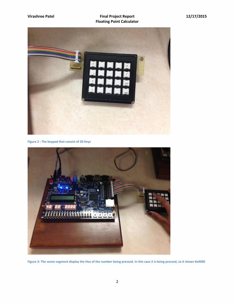
Figure 2 : The keypad that consist of 20 Keys
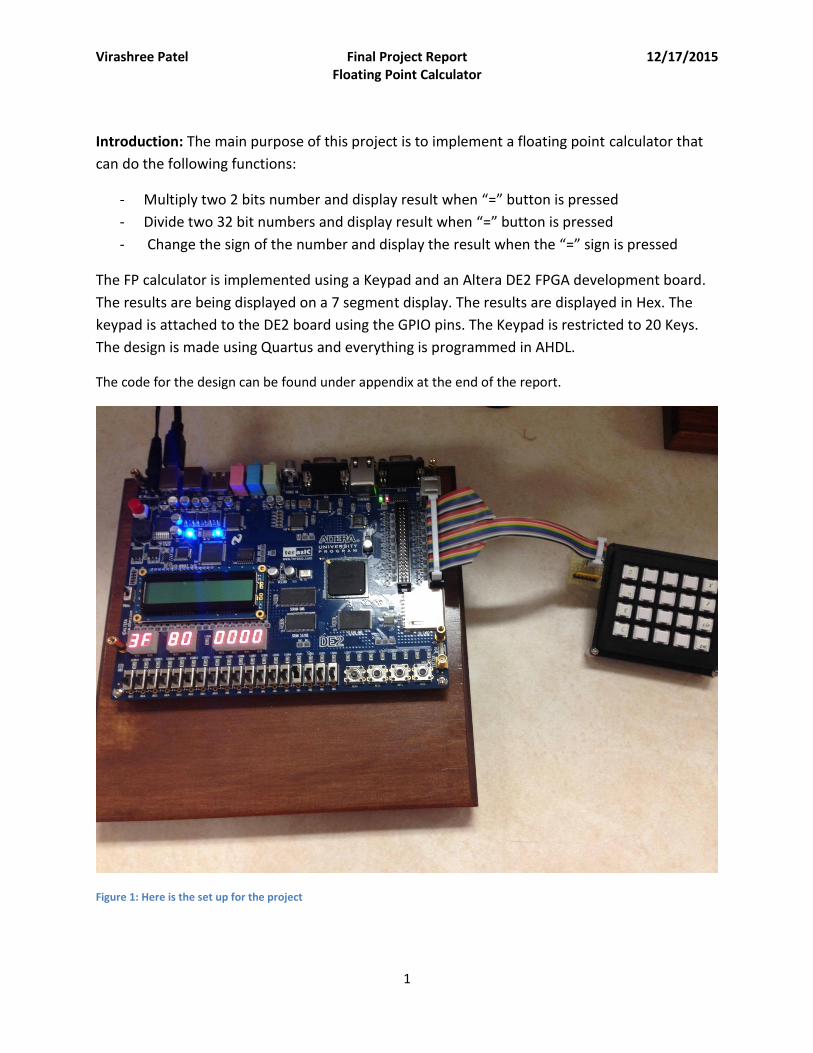
Figure 3: The seven segment display the Hex of the number being pressed. In this case 2 is being pressed, so it shows 0x4000
Virashree Patel Final Project Report 12/17/2015 Floating Point Calculator
3
For this project the IEEE 754, 32 bit floating point standard is being used. The numbers being displayed
on the 7 – Segment display are Hexadecimal number as it can be seen from figure 3.
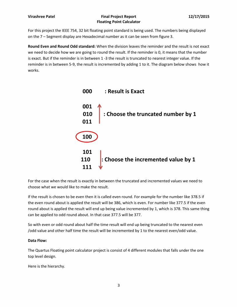
Round Even and Round Odd standard: When the division leaves the reminder and the result is not exact
we need to decide how we are going to round the result. If the reminder is 0, it means that the number
is exact. But if the reminder is in between 1 -3 the result is truncated to nearest integer value. If the
reminder is in between 5-9, the result is incremented by adding 1 to it. The diagram below shows how it
works.
000 : Result is Exact
001 010 : Choose the truncated number by 1
011
100
101 110 : Choose the incremented value by 1
111
For the case when the result is exactly in between the truncated and incremented values we need to
choose what we would like to make the result.
If the result is chosen to be even then it is called even round. For example for the number like 378.5 if
the even round about is applied the result will be 386, which is even. For number like 377.5 if the even
round about is applied the result will end up being value incremented by 1, which is 378. This same thing
can be applied to odd round about. In that case 377.5 will be 377.
So with even or odd round about half the time result will end up being truncated to the nearest even
/odd value and other half time the result will be incremented by 1 to the nearest even/odd value.
Data Flow:
The Quartus Floating point calculator project is consist of 4 different modules that falls under the one
top level design.
Here is the hierarchy.
Virashree Patel Final Project Report 12/17/2015 Floating Point Calculator
4
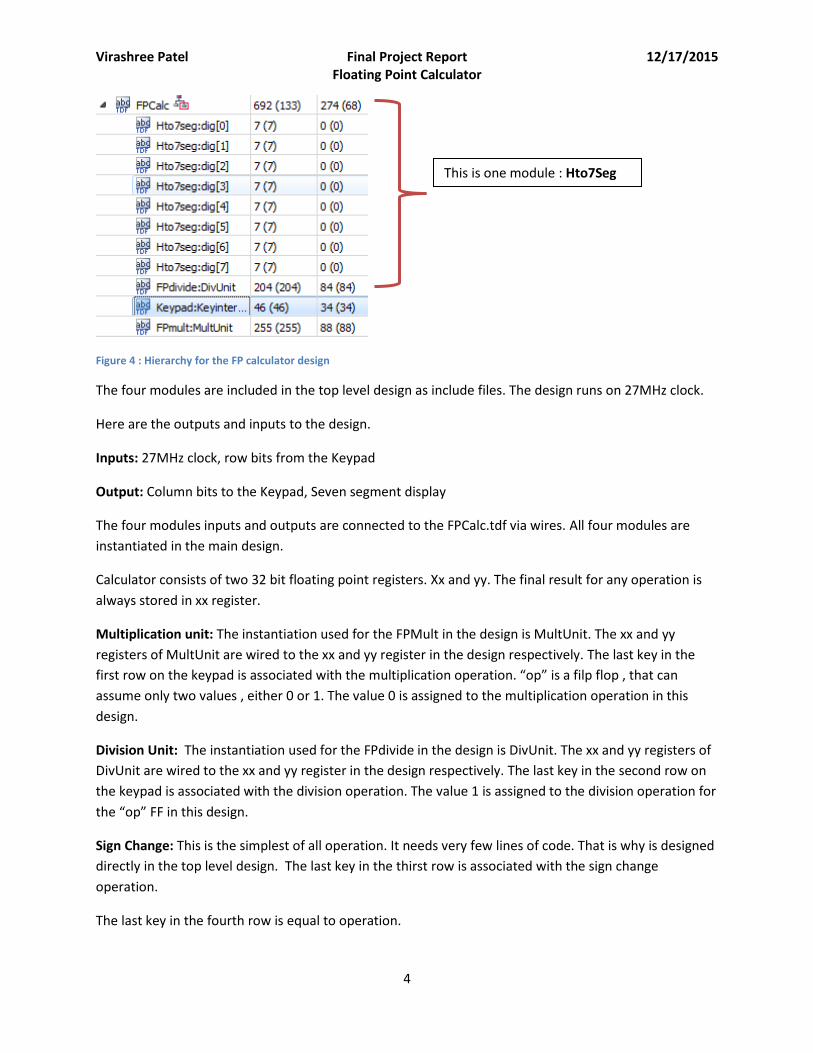
Figure 4 : Hierarchy for the FP calculator design
The four modules are included in the top level design as include files. The design runs on 27MHz clock.
Here are the outputs and inputs to the design.
Inputs: 27MHz clock, row bits from the Keypad
Output: Column bits to the Keypad, Seven segment display
The four modules inputs and outputs are connected to the FPCalc.tdf via wires. All four modules are
instantiated in the main design.
Calculator consists of two 32 bit floating point registers. Xx and yy. The final result for any operation is
always stored in xx register.
Multiplication unit: The instantiation used for the FPMult in the design is MultUnit. The xx and yy
registers of MultUnit are wired to the xx and yy register in the design respectively. The last key in the
first row on the keypad is associated with the multiplication operation. “op” is a filp flop , that can
assume only two values , either 0 or 1. The value 0 is assigned to the multiplication operation in this
design.
Division Unit: The instantiation used for the FPdivide in the design is DivUnit. The xx and yy registers of
DivUnit are wired to the xx and yy register in the design respectively. The last key in the second row on
the keypad is associated with the division operation. The value 1 is assigned to the division operation for
the “op” FF in this design.
Sign Change: This is the simplest of all operation. It needs very few lines of code. That is why is designed
directly in the top level design. The last key in the thirst row is associated with the sign change
operation.
The last key in the fourth row is equal to operation.
This is one module : Hto7Seg

Virashree Patel Final Project Report 12/17/2015 Floating Point Calculator
5
Adding new operations: if the new operation like addition and subtraction are to be added to the
calculator design we will need two new modules. FPSub and FRAdd. Two separate keys will be needed
on the calculator that represents Addition and Subtraction.
The design of these two modules will be quite similar to the Multiplication or division unit only the state
machine will be simpler for this operation. We will need two floating point registers that we can use for
the add / sub operations and that will be wired to the top level design the same way we wired the other
two modules.
Control Units: Here are the state diagrams for the controller, multiplication, division and Keypad.
Figure 5 : State Diagram for Controller
Figure 6 : State Diagram for multiplication
Virashree Patel Final Project Report 12/17/2015 Floating Point Calculator
6
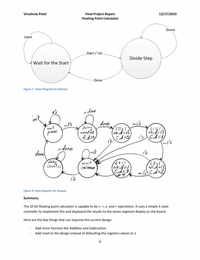
Figure 7 : State Diagram for Division
Figure 8: State Diagram for Keypad
Summary:
The 32 bit floating point calculator is capable to do ×, ÷, ±, and = operations. It uses a simple 3 state
controller to implement this and displayed the results to the seven segment display on the board.
Here are the few things that can improve the current design:
- Add more function like Addition and Subtraction
- Add reset to the design instead of defaulting the registers values to 1
Virashree Patel Final Project Report 12/17/2015 Floating Point Calculator
7
- Add an ON/OFF switch
- Being able to store the result after doing one operation to do more operations on it
Other than these we can add in a lot more other features to the design to make it better and more
versatile.
Appendix:
Virashree Patel Final Project Report 12/17/2015 Floating Point Calculator
8
FPclac.tdf
include "FPmult.inc"; include "FPdivide.inc"; include "Hto7seg.inc"; include "Keypad.inc"; Subdesign FPCalc ( Clk27M :Input; r[0..3] :Input; c[0..3] :Output; SevenSeg[55..0] :Output; -- results showm on 7-seg display ) Variable xx[31..0], yy[31..0] :Dff; dig[7..0] :Hto7seg; op :Dff; MultUnit :FPmult; DivUnit :FPdivide; Keyinterface :Keypad; key1,key2,key3,key4 :Node; keyCS,keyDiv,keyMult :Node; keyEq,keyUnused,newkey :Node; State :Machine With States(Init,Keys,Oper); Begin xx[].clk = Clk27M; yy[].clk = Clk27M; State.clk = Clk27M; op.clk = Clk27M; MultUnit.Clk = Clk27M; MultUnit.xx[] = xx[]; MultUnit.yy[] = yy[]; DivUnit.Clk = Clk27M; DivUnit.xx[] = xx[]; DivUnit.yy[] = yy[]; Keyinterface.Clk27 = Clk27M; Keyinterface.r[] = r[]; newkey = Keyinterface.nk; c[] = Keyinterface.c[]; -- prod[].d = MultUnit.prod[]; -- quo[].d = DivUnit.quo[]; -- prod[].clk = CLK27M; -- quo[].clk = CLK27M; -- MultDone = MultUnit.MultDone;
Virashree Patel Final Project Report 12/17/2015 Floating Point Calculator
9
-- DivDone = DivUnit.DivDone; dig7.in[] = xx[31..28]; dig6.in[] = xx[27..24]; dig5.in[] = xx[23..20]; dig4.in[] = xx[19..16]; dig3.in[] = xx[15..12]; dig2.in[] = xx[11..8]; dig1.in[] = xx[7..4]; dig0.in[] = xx[3..0]; SevenSeg[55..49] = dig7.out[]; SevenSeg[48..42] = dig6.out[]; SevenSeg[41..35] = dig5.out[]; SevenSeg[34..28] = dig4.out[]; SevenSeg[27..21] = dig3.out[]; SevenSeg[20..14] = dig2.out[]; SevenSeg[13..7] = dig1.out[]; SevenSeg[6..0] = dig0.out[]; -- Decoded Keys for the Keypad key1 = Keyinterface.Rn[]==0 & Keyinterface.Cn[]==0; key2 = Keyinterface.Rn[]==0 & Keyinterface.Cn[]==1; key3 = Keyinterface.Rn[]==0 & Keyinterface.Cn[]==2; key4 = Keyinterface.Rn[]==0 & Keyinterface.Cn[]==3; keyMult = Keyinterface.Rn[]==0 & Keyinterface.Cn[]==4; keyDiv = Keyinterface.Rn[]==1 & Keyinterface.Cn[]==4; keyCS = Keyinterface.Rn[]==2 & Keyinterface.Cn[]==4; -- +/- (change-sign key) keyEq = Keyinterface.Rn[]==3 & Keyinterface.Cn[]==4; -- = (the equal key) keyUnused = Keyinterface.Rn[]!=0 & Keyinterface.Cn[]!=4; -- assuming bottom left 4x3 key area not used -- The following is the main state machine -- most activities happen in the Keys state. -- A value must be assigned to xx[], yy[], op and next State for every possible -- condition in each state WITHOUT OVERLAP (setting it to different things in -- conditions that overlap so both are true). I think I have done that below, -- but I have not reread it or tested it in any way. Case State Is When Init => xx[].d = H"3F800000"; -- Initial value is 1.0 yy[].d = H"3F800000"; -- Initial value is 1.0 -- op will become 0 which specifies multiply State = Keys; When Keys => -- first handle the no keypress condition and unused keys (lower left 4x3)
Virashree Patel Final Project Report 12/17/2015 Floating Point Calculator
10
If !newkey # newkey & keyUnused Then xx[].d = xx[]; yy[].d = yy[]; op.d = op; State = Keys; End If; -- -- the following section handles the multiply and divide keys -- If newkey & (keyMult # keyDiv) Then -- yy[].d = xx[]; xx[].d = xx[]; State = Keys; -- op.d = keyDiv; -- this sets op = 0 for Mult and op = 1 for Div -- End If; If newkey & keyMult Then yy[].d = xx[]; xx[].d = xx[]; State = Keys; op.d = B"0"; End If; If newkey & keyDiv Then yy[].d = xx[]; xx[].d = xx[]; State = Keys; op.d = B"1"; End If; -- -- Handle the change-sign keypress If newkey & keyCS Then yy[].d = yy[]; op.d = op; State = Keys; xx[].d = (!xx31,xx[30..0]); End If; -- Handle the number keys If newkey & key1 Then yy[].d = yy[]; op.d = op; State = Keys; xx[].d = H"3F800000"; End If; -- 1.0 If newkey & key2 Then yy[].d = yy[]; op.d = op; State = Keys; xx[].d = H"40000000"; End If; -- 2.0 If newkey & key3 Then yy[].d = yy[]; op.d = op; State = Keys; xx[].d = H"40400000"; End If; -- 3.0 If newkey & key4 Then yy[].d = yy[]; op.d = op; State = Keys; xx[].d = H"41200000"; End If; -- 10.0 -- next handle the equal sign If newkey & keyEq Then yy[].d = yy[]; op.d = op; State = Oper; xx[].d = xx[]; MultUnit.start = !op; DivUnit.start = op; End If; When Oper => yy[].d = yy[]; op.d = op; If (MultUnit.MultDone # DivUnit.DivDone) Then -- only the operation started can assert done State = Keys; xx[].d = MultUnit.prod[] + DivUnit.quo[]; -- one will be zero so not harm other Else State = Oper; xx[].d = xx[]; End If;
Virashree Patel Final Project Report 12/17/2015 Floating Point Calculator
11
End Case; End; FPmult.tdf Subdesign FPmult ( xx[31..0], yy[31..0], Clk, Start :Input; -- fp numbers to multiply & start signal prod[31..0], MultDone :Output; -- product and a done signal ) Variable S, E[9..0], A[23..0], B[23..0] :Dff; R, SB, P[24..0], MultDone :Dff; Done, Rneed :Node; State :Machine With States(Wait,Step,Shift); Begin S.clk = Clk; E[].clk = Clk; A[].clk = Clk; B[].clk = Clk; State.clk = Clk; R.clk = Clk; SB.clk = Clk; P[].clk = Clk; MultDone.clk = Clk; Done = (A[]==0)&!P24; Rneed = R&SB # P0&R&!SB; prod[] = (S,E[7..0],P[22..0]); Case State Is When Wait => If Start Then S.d = xx[31] $ yy[31]; A[].d = (1,xx[22..0]); B[].d = (1,yy[22..0]); E[].d = (0,xx[30..23]) + (0,yy[30..23]) - 127 - 24; State = Step; Else State = Wait; --Note: All Dffs go to zero so prod[] becomes zero End If; When Step => S.d = S; R.d = P0; SB.d = SB # R; A[].d = (0,A[23..1]); B[].d = B[]; If !Done Then P[].d = (0,P[24..1]) + (0,A0&B[]); E[].d = E[] + 1; State = Step; Else E[].d = E[]; If !Rneed Then P[].d = P[]; MultDone.d = B"1"; State = Wait; Else P[].d = P[] + 1; State = Shift; End If; End If; When Shift => S.d = S; MultDone.d = B"1"; State = Wait; If P24 Then
Virashree Patel Final Project Report 12/17/2015 Floating Point Calculator
12
E[].d = E[] + 1; P[].d = (0,P[24..1]); Else E[].d = E[]; P[].d = P[]; End If; End Case; End; FPdivide.tdf Subdesign FPdivide ( xx[31..0], yy[31..0], Clk, Start :Input; -- fp divisor, dividend & start signal quo[31..0], DivDone :Output; -- quotient and a done signal ) Variable S, E[9..0], A[24..0], B[24..0] :Dff; Q[23..0], DivDone :Dff; Neg, Done, Rneed, AmB[24..0] :Node; State :Machine With States(Wait,Step); Begin S.clk = Clk; E[].clk = Clk; A[].clk = Clk; B[].clk = Clk; Q[].clk = Clk; DivDone.clk = Clk; State.clk = Clk; Done = Q23; Rneed = A[]>B[] # A[]==B[]&Q0; AmB[] = A[] - B[]; Neg = AmB24; quo[] = (S,E[7..0],Q[22..0]); Case State Is When Wait => If Start Then S.d = xx[31] $ yy[31]; A[].d = (01,yy[22..0]); B[].d = (01,xx[22..0]); E[].d = (0,yy[30..23]) - (0,xx[30..23]) + 127 + 24; State = Step; Else State = Wait; --Note: All Dffs go to zero so prod[] becomes zero End If; When Step => S.d = S; B[].d = B[]; If !Neg Then A[].d = (AmB[23..0],0); Else A[].d = (A[23..0],0); End If; If !Done Then E[].d = E[] - 1; Q[].d = (Q[22..0],!Neg); State = Step; Else E[].d = E[]; Q[].d = (Q[] + (0,Rneed)); DivDone.d = B"1"; State = Wait; End If; End Case; End; Hto7seg.tdf
Virashree Patel Final Project Report 12/17/2015 Floating Point Calculator
13
Subdesign Hto7seg ( in[3..0] :Input; %hex value in% out[6..0] :Output; %7 segents out% ) Variable zero,one,two,three,four,five,six,seven, eight,nine,AA,BB,CC,DD,EE,FF :node; Begin zero = in[]==0; one = in[]==1; two = in[]==2; three = in[]==3; four = in[]==4; five = in[]==5; six = in[]==6; seven = in[]==7; eight = in[]==8; nine = in[]==9; AA = in[]==10; BB = in[]==11; CC = in[]==12; DD = in[]==13; EE = in[]==14; FF = in[]==15; out0 = !(zero # two # three # five # six # seven # eight # nine # AA # CC # EE # FF); out1 = !(zero # one # two # three # four # seven # eight # nine # AA # DD); out2 = !(zero # one # three # four # five # six # seven # eight # nine # AA # BB # DD); out3 = !(zero # two # three # five # six # eight # BB # CC # DD # EE); out4 = !(zero # two # six # eight # AA # BB # CC # DD # EE # FF); out5 = !(zero # four # five # six # eight # nine # AA # BB # CC # EE # FF); out6 = !(two # three # four # five # six # eight # nine # AA # BB # DD # EE # FF); End; Keypad.tdf Subdesign Keypad ( Clk27 : Input ; r[0..3] : Input ; --ro[0..3],st0o : Output; c[0..3] : Output; Rn[1..0] : Output; Cn[2..0] : Output; nk : Output ; )
Virashree Patel Final Project Report 12/17/2015 Floating Point Calculator
14
Variable %s[2..0] : Dff ;% ctr[19..0] : Dff ; nk,Rn[1..0],Cn[2..0] : Dff; done : Node ; count : Node ; %st0,st1,st2,st3,st4,st5,st6,st7 : Node ;% allones : Node ; State : Machine With States(st0,st1,st2,st3,st4,st5,st6,st7); Begin --ro[] = r[]; --st0o = st0; Ctr[].clk = Clk27; Ctr[].d = count & (Ctr[].q+1); Rn[].clk = Clk27; Cn[].clk = Clk27; nk.clk = Clk27; Rn1.d = st1 & (!r2 # !r3) # !st1 & Rn1; Rn0.d = st1 & (!r1 # !r3) # !st1 & Rn0; Cn[].d = Cn[].q & (st6 # st7 # st0 ); --Cn0 = c1 # c3 ; --Cn1 = c2 # c3 ; --Cn2 = Cn2 & !Cn2; -- --c0 = State == st2 & nk ; --c1 = State == st3 & nk ; --c2 = State == st4 & nk ; --c3 = State == st5; %c4 = c4 & !c4;% done = Ctr19; %r[0..3] = !(!c0 & r[0..3] & c0 # !c1 & r[0..3] & c1 # !c2 & r[0..3] & c2 # !c3 & r[0..3] & c3 # !c4 & r[0..3]& c4) ;% allones = r0 & r1 & r2 & r3; nk.d = allones & (st2 # st3 # st4) # st5; %s2.d = st2 & allones & nk # st3 & allones & nk # st4 & allones & nk # st3 & !allones # st4 & !allones # st5 # st6 & !allones # st6 & allones # st7 & !done ; s1.d = st1 & done # st2 & allones & nk # st2 & !allones # st3 & allones & nk # st4 & allones & nk # st5 # st6 & !allones # st6 & allones # st7 & !done ;

Virashree Patel Final Project Report 12/17/2015 Floating Point Calculator
15
s0.d = st0 & !allones # st1 & !done # st2 & !allones # st4 & !allones # st6 & allones # st7 & !done;% State.clk = Clk27; case State Is When st0 => If !allones then State = st1; Else State = st0; End If; When st1 => count = b"1" ; If done then State = st2; Else State = st1 ; End If; When st2 => c0 = b"1" ; If allones then State = st6 ; Cn[].d = 0; End If; If !allones then State = st3 ; End If; When st3 => c1 = b"1" ; If allones then State = st6 ; Cn[].d = 1; End If; If !allones then State = st4; End If; When st4 => c2 = b"1" ; If allones then State = st6 ; Cn[].d = 2; End If; If !allones then State = st5; End If; When st5 => c3 = b"1" ; State = st6; Cn[].d = 3 & allones # 4 & !allones; When st6 => If allones then State = st7; Else State = st6; End If; When st7 => count = b"1"; If done then State = st0; Else State = st7; End If; End Case; End;