Embed Size (px)
Citation preview

ACADEMIC REGULATIONS COURSE STRUCTURE
ANDDETAILED SYLLABUS
For
M.Tech
(DEPARTMENT OF ELECTRICAL AND ELECTRONICS ENGINEERING)
(Applicable for the batches admitted from 2016-2017)
ADITYA INSTITUTE OF TECHNOLOGY AND
MANAGEMENT (AUTONOMOUS)Approved by AICTE, Accredited by NBA & NAAC,
Recognised under 2(f)12(b) of UGC Permanently Affiliated to JNTUK, Kakinada.
K.Kotturu, Tekkali, Srikakulam-532 201, Andhra Pradesh.
POWER ELECTRONICS AND DRIVES
AR-

VISION OF THE INSTITUTE
To evolve into a premier engineering institute in the country by continuously enhancing
the range of our competencies, expanding the gamut of our activities and extending the frontiers
of our operation.
MISSION OF THE INSTITUTE
Synergizing knowledge, technology and human resource, we impart the best quality
education in Technology and Management. In the process, we make education more objective so
that efficiency for employability increases on a continued basis.
VISION OF THE DEPARTMENT
The department of Electrical and Electronics Engineering is committed to innovation and
excellence in teaching, research, service and provide programs of the high quality, collaborative
efforts with industry to produce world class engineering professionals.
MISSION OF THE DEPARTMENT
1. To inculcate value based, socially committed professionalism to the cause of overall
development of students and society.
2. Cultivate the spirit of entrepreneurship and the connection between engineering and business
that encourages technology commercialization.
3. Improve continuously the engineering pedagogical methods employed in delivering its
academic programs.
4. Evolve thoughtfully in response to the needs of industry, society and the changing world.

PROGRAM EDUCATIONAL OBJECTIVES
PEO1 Graduates of PED will be successful professionals in industry, government, academia, research, entrepreneurial pursuit and consulting firmsPEO2 Graduates will be future researchers / scientists with innovative ideas for a sustainable development.PEO3 Graduates will be improve their technical and intellectual capabilities through lifelong
learning process so as to become good teachers, either in a class or to juniors in industry.
PEO4 Graduates will continue to pursue professional development, including continuing or
advanced education relevant to their career growth and to create enthusiasm for lifelong learning.
PROGRAM OUTCOMES
a. Will be a professional workforce in the areas of “Static Power Electronics Converters”, “Power Electronic Converter fed Electrical Drives” and “Power Quality”.
b. Will be able to apply soft computing techniques for Power Electronic Systems and Electric Drives.
c. Will be able to understand large scale Power Electronic Converter Systems, Electric Drives and issues involved through modeling, analysis and simulation.
d. Will be able to apply present day techniques and tools to solve Power electronic and electric drives problems relevant to current needs.
e. Will be able to use state of the art simulation tools such as MATLAB, SIMULINK, PLEXIM, SABER, OPALRT Lab, DSPACE, MULTISIM, LABVIEW and other Tools.
f. Will be capable of contributing positively to collaborative and multidisciplinary research to achieve common goals.
g. Will demonstrate knowledge and understanding of electrical and electronics engineering and management principles and apply the same for efficiently carrying out projects with due consideration to economical and financial factors.
h. Will be able to communicate confidently, make effective presentations and write good reports to engineering community and society.
i. Will recognize the need for lifelong learning and have the ability to do it independently.j. Will become aware of social issues and shall contribute to the community for sustainable
development of society.k. Will be able to independently observe and examine critically the outcomes of his/her
actions and apply corrective measures subsequently and move forward positively through a self corrective approach.
l. Will able to continuously update their knowledge on contemporary issues.m. Will able to imbibe the values of honesty and integrity.

ACADEMIC REGULATIONS - 2016
(Effective for the students admitted into first year from academic year 2016-2017)
The M.Tech Degree of the Aditya Institute of Technology and Management (Autonomous), Tekkali shall be conferred on candidates who are admitted to the program and fulfill all the requirements for the award of the Degree.
1.0 ELIGIBILITY FOR ADMISSIONS:
Admission to the above program shall be made subject to the eligibility, qualifications and specialization prescribed by the University from time to time. Admissions shall be made on the basis of merit rank obtained by the qualifying candidate in GATE / PGCET, subject to reservations prescribed by the Govt. of AP from time to time.
2.0 AWARD OF M. Tech DEGREE:
2.1 A student shall be declared eligible for award of the M.Tech degree, if he/she pursues a course of study and completes it successfully in not less than two academic years and not more than four academic years.
2.2 A student, who fails to fulfill all the academic requirements for the award of the degree within four academic years from the year of his/her admission, shall forfeit his/her seat in M.Tech course.
2.3 The minimum instruction for each semester 95 clear instruction days.
3.0 ATTENDANCE3.1 A candidate shall be deemed to have eligibility to write End Semester examinations if he/she has put in a minimum of 75% of attendance in aggregate of all the subjects.
3.2 Condonation of shortage of attendance up to 10% (65% and above, and below 75%) may be given by the College academic committee.
3.3 Condonation of shortage of attendance shall be granted only on genuine and valid reasons on representations by the candidate with supporting evidence.
3.4 Shortage of attendance below 65% shall in NO case be condoned.
3.5 A candidate shall not be promoted to the next semester unless he/she fulfills the attendance requirements of the present semester.
3.6 A stipulated fee shall be payable towards condonation of shortage of attendance.
4.0 COURSE OF STUDY:
The following specializations are offered at present for the M.Tech course of study.
1 Digital Electronics and Communication Systems2 VLSI System Design3 Power Electronics and Drives4 Computer Science and Engineering5 Structural Engineering 6 Thermal Engineering
5.0 EVALUATION
The performance of the candidate in each semester shall be evaluated subject-wise, with a Maximum of 100 marks for theory and100 marks for Laboratory, on the basis of Internal Evaluation and End Semester Examination.
5.1 For the theory subjects 60 marks shall be awarded based on the performance in the End Semester Examination. Out of 40 internal marks 30 marks are assigned for subjective exam, 5 marks for assignments and 5 marks for seminars. The internal evaluation for 30 marks shall be made based on the average of the marks secured in the two Mid Term-Examinations conducted, one in the middle of the Semester and the other immediately after the completion of instruction. Each midterm examination shall be conducted of duration of 120 minutes and question paper shall contain 4 questions. The student should answer all 4 questions.
5.2 For practical subjects, 60 marks shall be awardees based on the performance in the End Semester Examinations. Out of 40 internal marks 20 marks are assigned based on day to day evaluation and 20 marks are assigned based on the internal test.
5.3 There shall be a technical seminar presentation during 3rd semester. For technical seminar, a student under the supervision of a faculty member, shall collect the literature on a topic and critically review the literature and submit it to the Department in a report form and shall make an oral presentation before the Departmental Committee. The Departmental Committee consists of Head of the Department, supervisor and two other senior faculty members of the department. For technical seminar there will be only internal evaluation of 100 marks. A candidate has to secure a minimum of 50% to be declared successful.
5.4 A candidate shall be deemed to have secured the academic requirement in a subjectif he/she secures a minimum of 40% of marks in the End Examination and a minimum aggregate of 50% of the total marks in the End Semester Examination and Internal Evaluation taken together.
5.5 In case the candidate does not secure the minimum academic requirement in any subject (as specified in 5.4) he has to reappear for the supplementary Examination in that subject.
5.6 The viva-voce examination shall be conducted at the end of the course work after pass in all subjects.
5.7 Laboratory examination for M.Tech courses must be conducted with two Examiners, one of them being Laboratory Class Teacher and second examiner shall be external examiner.
6.0 EVALUATION OF PROJECT/DISSERTATION WORK:
Every candidate shall be required to submit thesis or dissertation after taking up a topic approved by the Project Review Committee.
6.1 A Project Review Committee (PRC) shall be constituted with Principal as chair person, Head of the department and two other senior faculty members of the concerned department (one will be the guide).
6.2 Registration of Project Work: A candidate is permitted to register for the project work after satisfying the attendance requirement of all the subjects(theory and practical subjects).
6.3 After satisfying 6.2, a candidate has to submit, in consultation with his project supervisor, the title, objective and plan of action of his project work (Based on a publication in a Peer Reviewed Journal) to the Project Review Committee for its approval before the second semester end examinations. After obtaining the approval of the Committee the student can initiate the Project work after the second semester end examinations.
6.4 Every candidate shall work on projects approved by the PRC of the college.
6.5 If a candidate wishes to change his supervisor or topic of the project he can do so with approval of the PRC. However, the Project Review Committee ( PRC) shall examine whether the change of topic/supervisor leads to a major change of his initial plans of project proposal. If so, his date of registration for the project work starts from the date of change of Supervisor or topic as the case may be.
6.6 A candidate shall submit status report in two stages at least with a gap of 3 months between them.
6.7 The work on the project shall be initiated in the beginning of the second year/III semester and the duration of the project is for two semesters. The candidate shall identify the problem, Literature survey, design/modeling part of the problem i.e. almost 35% of his dissertation/project work should complete in the III semester itself and it will be evaluated by PRC. If the candidate fails to get the satisfactory report, he has to re-register for the project/dissertation work.
6.8 A candidate shall be allowed to submit the project report only after fulfilling the attendance requirements of all the semesters with approval of PRC and not earlier than 40 weeks from the date of registration of the project work. For the approval of PRC the candidate shall submit the draft copy of thesis to the Principal (through Head of the Department) and shall make an oral presentation before the PRC.
6.9 The Candidate may be permitted to submit the Project Report If only the work is Published/Accepted to be Published in a Journal / International conference of repute and relevance.
6.10 Three copies of the Project Thesis certified by the supervisor shall be submitted to the College/ School/ Institute.
6.11 The thesis shall be adjudicated by external examiner from outside the college.
6.12The viva-voce examination shall be conducted by a board consisting of the supervisor, Head of the Department and the examiner outside the college who adjudicated the Thesis.
6.13 The student has to clear all the subjects of M.Tech course before submission of the project thesis/ dissertation
The Board shall jointly report candidates work as:
A. ExcellentB. GoodC. SatisfactoryD. Unsatisfactory
Head of the Department shall coordinate and make arrangements for the conduct of viva-voce examination. If the report of the viva-voce is unsatisfactory, the candidate will retake the viva-voce examination after three months. If he fails to get a satisfactory report at the second viva-voce examination, the candidate may be asked to submit a new project proposal to PRC starting with 6.5

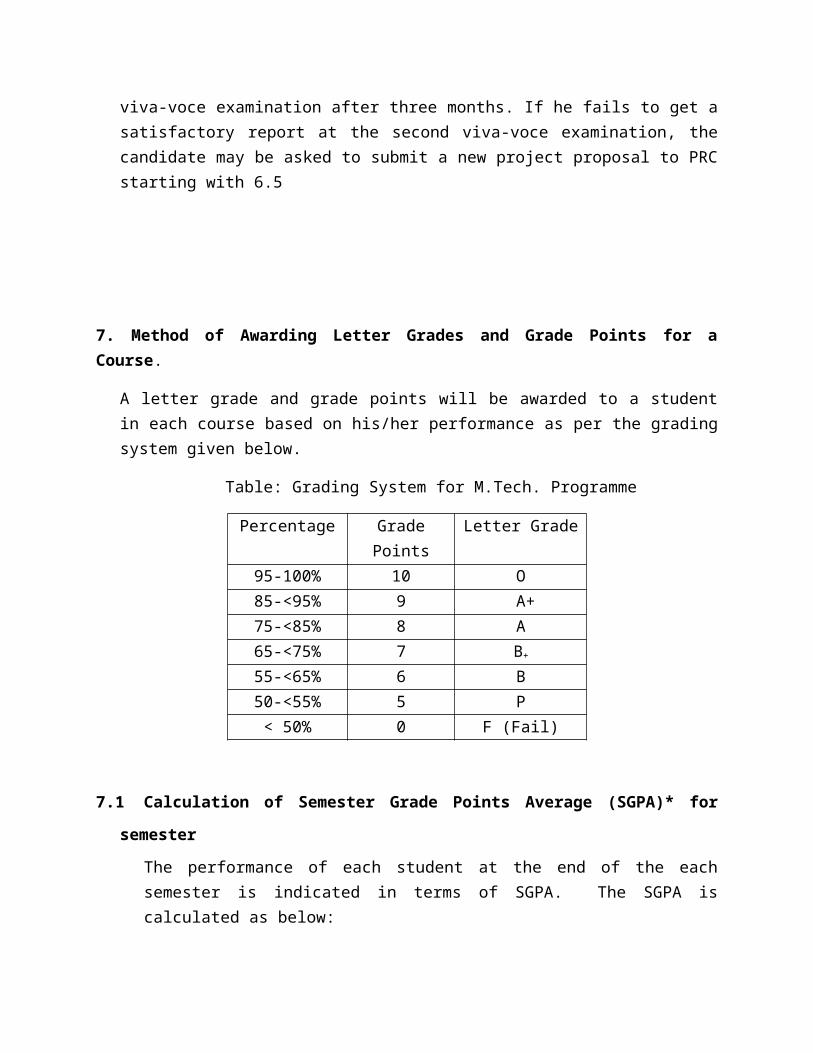
7. Method of Awarding Letter Grades and Grade Points for a Course.
A letter grade and grade points will be awarded to a student in each course based on his/her performance as per the grading system given below.
Table: Grading System for M.Tech. Programme
Percentage Grade Points Letter Grade95-100% 10 O85-<95% 9 A+75-<85% 8 A65-<75% 7 B+
55-<65% 6 B50-<55% 5 P
< 50% 0 F (Fail)
7.1 Calculation of Semester Grade Points Average (SGPA)* for semester
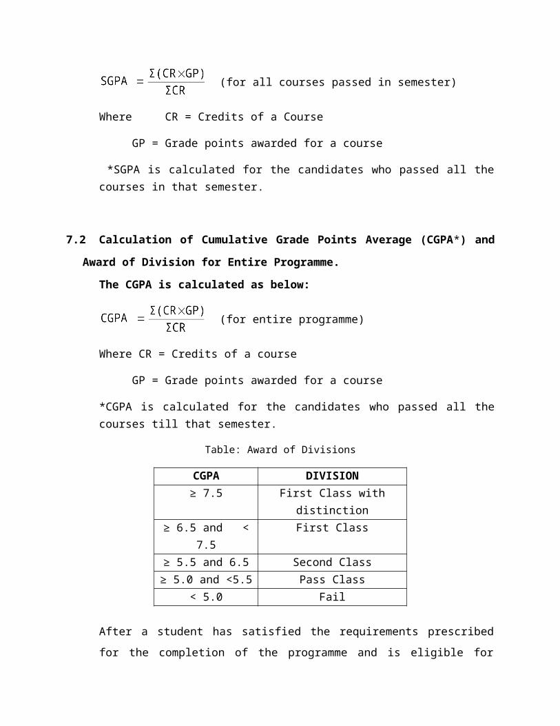
The performance of each student at the end of the each semester is indicated in terms of SGPA. The SGPA is calculated as below:
(for all courses passed in semester)
Where CR = Credits of a Course
GP = Grade points awarded for a course
*SGPA is calculated for the candidates who passed all the courses in that semester.
7.2 Calculation of Cumulative Grade Points Average (CGPA*) and Award of Division for
Entire Programme.
The CGPA is calculated as below:
(for entire programme)
Where CR = Credits of a course
GP = Grade points awarded for a course
*CGPA is calculated for the candidates who passed all the courses till that semester.
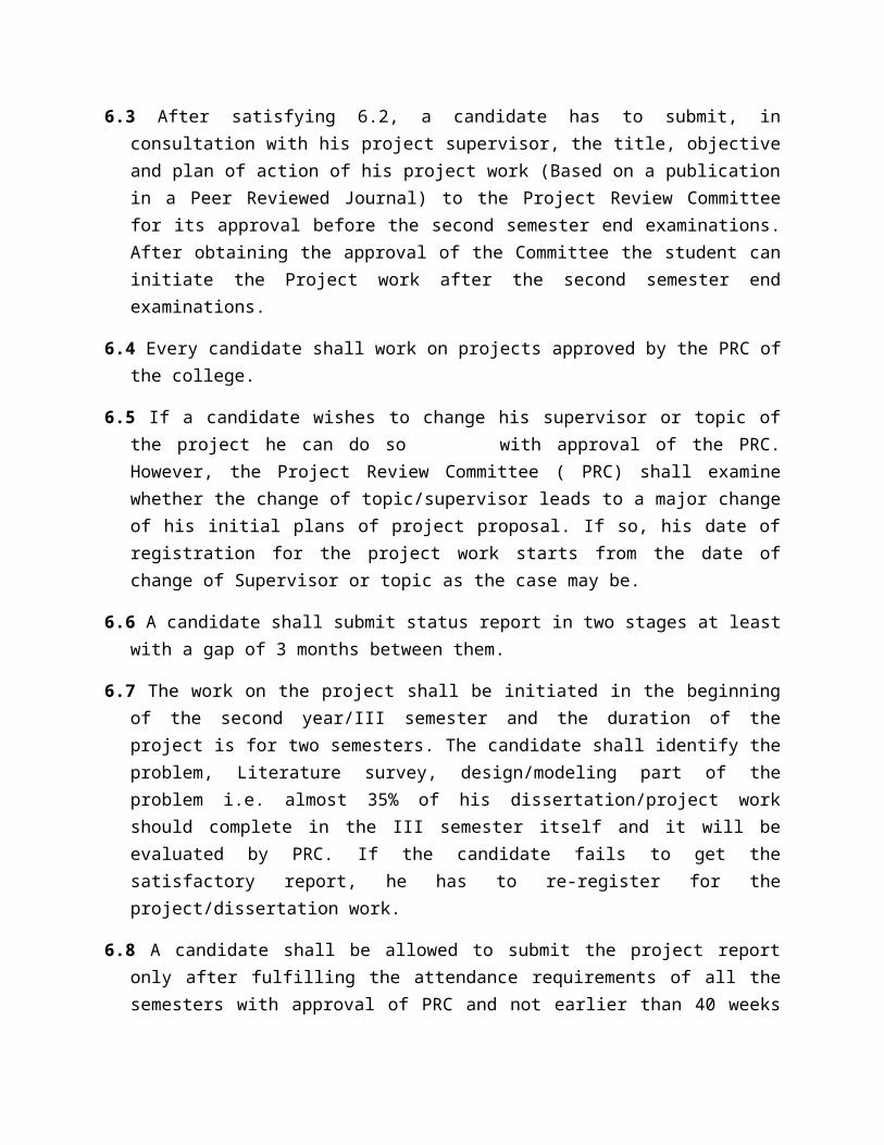
Table: Award of Divisions
CGPA DIVISION≥ 7.5 First Class with distinction
≥ 6.5 and < 7.5 First Class≥ 5.5 and 6.5 Second Class
≥ 5.0 and <5.5 Pass Class< 5.0 Fail
After a student has satisfied the requirements prescribed for the completion of the
programme and is eligible for receiving the award of M.Tech. Degree, he shall be placed
in one of the above divisions.
8.0 WITH-HOLDING OF RESULTS:
If the candidate has not paid any dues to the college or if any case of indiscipline is pending against him / her, the result of the candidate will be withheld and he/she will not be allowed into the next higher semester. The issue of the degree is liable to be with held in such cases.
9.0 TRASITORY REGULATIONS:
Candidate who have discontinued or have been detained for want of attendance or who have failed after having undergone the course are eligible for admission to the same or equivalent subjects as and when subjects are offered, subject to 5.5 and 2.0
10.0 GENERAL:
10.1 The academic regulations should be read as a whole for purpose of any Interpretation.
10.2 In case of any doubt or ambiguity in the interpretation of the above rules, the decision of the Principal is final.
10.3 The Institute may change or amend the academic regulations and syllabus at any time and the changes and amendments made shall be applicable to all the students with effect from the date notified by the college.
10.4 Wherever the word he, him or his occur, it will also include she, her and hers.
* * * * *

COURSE STRUCTURE
I SEMESTERS.No Subject Code Subject L P C INT EXT
01 16MPE1001Electrical Machine Modeling andAnalysis 4 - 4 40 60
02 16MPE1002 Analysis of Power Electronic converters 4 - 4 40 6003 16MPE1003 Power Electronic control of DC drives 4 - 4 40 6004 16MPE1004 Micro controllers and Applications 4 - 4 40 60
05Elective-I
4 - 4 40 6016MPE1005 Modern control theory16MPE1006 Programmable logic controllers
06
Elective-II
4 - 4 40 6016MPE1007 Design and monitoring of Machines
16MPE1008 Non-conventional energy sources andapplications
07 16MPE1101 Power Electronics systems simulation Lab - 4 2 40 60Total 28 26 700
II SEMESTERS.No Subject Code Subject L P C INT EXT01 16MPE1009 Switched mode power converters 4 - 4 40 6002 16MPE1010 Power Electronic control of AC drives 4 - 4 40 6003 16MPE1011 Flexible AC Transmission systems 4 - 4 40 60
04 16MPE1012 Advanced Digital signal processing and applications 4 - 4 40 60
05Elective-III
4 - 4 40 6016MPE1013 Analysis of Dynamic systems16MPE1014 Intelligent control
06
Elective-IV
4 - 4 40 6016MPE1015 Power quality Management
16MPE1016 Energy auditing, conservation andManagement
07 16MPE1102 Power Electronics and Drives Lab - 4 2 40 60Total 28 26 700
III SEMESTERS.No Subject Code Subject C INT EXT
01 16MPE2201 Technical Seminar 2 100 -02 16MPE2202 Project work phase-I 12 - -
IV SEMESTERS.No Subject Code Subject C INT EXT
01 16MPE2203 Project work Phase-II 14 - -
L – Lecture hours/Week; P – Practical hours/ Week; C – Credits;
INT – Internal Marks; EXT – External Marks;
ELECTRICAL MACHINE MODELING AND ANALYSISL P C INT EXT4 0 4 40 60
16MPE1001Course Objectives:The main objective of the course is to:
Understand the basic concepts of modeling. Understand how the Reference Frame Theory helpful for modeling of electrical machines. Understand how to analysis and model the different electrical machines i.e. D.C and A.C
machines (D.C generator, D.C Motor, 3-phase induction motor & synchronous motor). Understand the dynamic analysis of synchronous machine under fault condition.
Course Outcomes:At the end of the course, the students will be able to:
CO1: Determine the developed torque in Kron’s primitive Machine and determine the dynamic model of a DC machine.
CO2: Determine the dynamic model & Small signal model of three phase induction machine based on the dq0 Transformation and determine instantaneous torque developed in an induction Machine which leads to advanced control strategies such as vector control and direct torque control.
CO3: Analyze and model the Symmetrical and Unsymmetrical Two phase induction machine.CO4: Analyze and model the three phase synchronous machine.CO5: Analyze the dynamic analysis of synchronous machine under three-phase fault
condition.
UNIT I: Basic Concepts of Modeling: Basic Two-pole Machine representation of Commutator machines, 3-phase synchronous machine with and without damper bars and 3-phase induction machine. Kron’s primitive Machine-voltage, current and Torque equations. Mathematical model of separately excited D.C motor – Steady State analysis-Transient State analysis- Sudden application of Inertia Load-Transfer function of Separately excited D.C Motor- Mathematical model of D.C Series motor, Shunt motor-Linearization Techniques for small perturbations.
UNIT II: Reference Frame Theory: Real time model of a two phase induction machine- Transformation to obtain constant matrices-three phase to two phase transformation-Power equivalence.

UNIT III: Dynamic Modeling & Small Signal Modeling of Three phase Induction Machine:Generalized model in arbitrary reference frame-Electromagnetic torque-Derivation of commonly used Induction machine models- Stator reference frame model-Rotor reference frame model-Synchronously rotating reference frame model-Equations in flux linkages-per unit model-Dynamic Simulation Small signal equations of Induction machine-derivation-DQ flux linkage model derivation-control principle of Induction machine.
UNIT IV:Symmetrical and Unsymmetrical Two phase Induction Machine: Analysis of symmetrical 2 phase induction machine-voltage and torque equations for unsymmetrical 2 phase induction machine-voltage and torque equations in stationary reference frame variables for unsymmetrical 2 phase induction machine-analysis of steady state operation of unsymmetrical 2 phase induction machine- single phase induction motor - Cross field theory of single-phase induction machine.
UNIT V: Modeling of Synchronous Machine:Synchronous machine inductances –voltage equations in the rotor’s dq0 reference frame-electromagnetic torque-current in terms of flux linkages-simulation of three phase synchronous machine- modeling of PM Synchronous motor.
UNIT VI: Dynamic Analysis of Synchronous Machine:Dynamic performance of synchronous machine, three-phase fault, comparison of actual and approximate transient torque characteristics, Equal area criteria.
TEXT BOOKS:1. Electric Motor Drives - Modeling, Analysis& control -R.Krishnan- Pearson Publications-1st
edition -20022. Analysis of Electrical Machinery and Drive systems – P.C.Krause, Oleg Wasynczuk, Scott
D.Sudhoff – Second Edition-IEEE Press
REFERENCE BOOKS:1. Generalized Theory of Electrical Machines – P.S.Bimbra-Khanna publications-5 th Edition-
19952. Dynamic simulation of Electric machinery using Matlab / Simulink –Chee Mun Ong-
Prentice Hall.

ANALYSIS OF POWER ELECTRONICS CONVERTERS
L P C INT EXT4 0 4 40 60
16MPE1002Course Objectives:The main objective of the course is to:
Introduce basic concepts of AC voltage controllers, AC-DC converters, concepts on Power factor converters and inverters.
Course Outcomes:At the end of the course, the students will be able to:
CO1: Describe the operation of dc-dc, dc-ac, ac-dc and ac-ac power converters.CO2: Explain the control characteristics of power semiconductor switching devicesCO3: Calculate the values of circuit parameters to limit output ripple voltages and currents of a
converter with specified valuesCO4: Evaluate the effects of various modulation techniques on the quality of input and output
waveforms.CO5: Analyze and evaluate the performance of a simple power circuit.
UNIT I: AC voltage Controllers: Single Phase AC Voltage Controllers with RL and RLE loads-ac voltage controller’s with PWM control-Effects of source and load inductances – synchronous tap changers –Application- numerical problems, Three Phase AC Voltage controllers-Analysis of Controllers with star and delta connected resistive, resistive – inductive loads-Effects of source and load inductances–Application- numerical problems.
UNIT II: Single Phase Ac-Dc converters: Single phase Half controlled and Fully controlled Converters with RL load– Evaluation of input power factor and harmonic factor-Continuous and Discontinuous load current-Power factor improvements-Extinction angle control-symmetrical angle control-PWM single phase sinusoidal PWM-Single phase series converters-numerical problems.
UNIT III:Three Phase Ac-Dc Converters: Three Phase ac-dc Converters- Half controlled and fully controlled Converters with RL load– Evaluation of input power factor and harmonic factor-Continuous and Discontinuous load current-three phase dual converters-Power factor improvements- three phase PWM-twelve pulse converters- numerical problems
UNIT IV:

Power Factor Correction Converters: Single-phase single stage boost power factor corrected rectifier, power circuit principle of operation, and steady state- analysis, three phase boost PFC converter.
UNIT V:PWM Inverters: Principle of operation-Voltage control of single phase inverters - sinusoidal PWM – modified PWM – phase displacement Control – Trapezoidal, staircase, stepped,harmonic injection and delta modulation – numerical problems, Voltage Control of Three Phase Inverters Sinusoidal PWM 60◦ PWM. Third Harmonic PWM- Space Vector Modulation- Comparison of PWM Techniques-current source inverters- Variable dc link inverter - numerical problems. UNITVI: Multi level inverters: Introduction, Multilevel Concept, Types of Multilevel Inverters- Diode-Clamped Multilevel Inverter, Principle of Operation, Features of Diode-Clamped Inverter, Improved Diode-Clamped Inverter- Flying-Capacitors Multilevel Inverter- Principle of Operation, Features of Flying-Capacitors Inverter- Cascaded Multilevel Inverter- Principle of Operation- Features of Cascaded Inverter- Switching Device Currents- DC-Link Capacitor Voltage Balancing- Features of Multilevel Inverters- Comparisons of Multilevel Converters.
TEXT BOOKS:
1. Power Electronics- Md.H.Rashid –Pearson Education Third Edition-20082. Power Electronics- Ned Mohan, Tore M.Undelan and William P.Robbins –John Wiley &
Sons -2nd Edition.
REFERENCE BOOKS:
1. Power Electronics – Lander – 2009.
2. Modern Power Electronics and AC Drives – B.K.Bose.
3. Power Converter Circuits – willian swpherd & Li zhang – Yes Dee Publishing Pvt.Ltd
POWER ELECTRONIC CONTROL OF DC DRIVES

L P C INT EXT4 0 4 40 60
16MPE1003
Course Objectives:The main objective of the course is to:
Provides basic understanding of main principles of DC drives, various modes of operation, control from converters and choppers, and also modeling of DC machines.
Course Outcomes:At the end of the course, the students will be able to:
CO1: Able to understand the concept of modeling and analysis of DC motors.CO2: Able to design controllers for closed loop and open loop transfer function of DC motor
drives.CO3: Able to analyze the controlled converter and DC chopper circuits.CO4: Able to Analyze the Dual Converter Control of DC motorCO5: Able to Distinguish the difference between PWM controller and hysteresis controller
UNIT I:Modeling of DC Machines: Theory of operation-Equivalent Circuit and Electromagnetic Torque- Electromechanical Modeling- State space modeling-Block diagram and Transfer functions.
UNIT II:Single Phase Controlled Converter DC Motor Drives: Principle of DC Motor Speed Control-Armature control-Field Control-armature and field controls. Single –phase semi converter and single-phase full converter fed Separately excited DC motor for continuous and discontinuous modes of operation- Problems.
UNIT III:Three Phase Controlled Converter DC Motor Drives: Three-phase semi converter and three-phase full converter Separately excited DC motor- for continuous and discontinuous modes of operation-Problems-Four Quadrant Operation using Dual Converters-Control modeling of three-phase converter-Two quadrant Three Phase Converter Controlled DC Motor Drive-Transfer Functions of the subsystems.
UNIT IV:
Design of Controllers: Current controller-First order Approximation of Inner Current Loop- speed controller- Simulation of one quadrant DC Motor Drive-The Motor equations-field in the speed feedback loop-Speed Controller- Current Reference Generator-Current Controller- Flow Chart for Simulation.
UNIT V:Chopper controlled DC Motor drives: Principle of operation of the chopper – four quadrant chopper circuit – chopper for inversion –chopper with other power devices – model of the chopper – input to the chopper – steady state analysis of chopper controlled DC motor drives – rating of the devices.
UNIT VI:Closed Loop Operation of Chopper controlled DC Motor drives: Closed loop operation of DC Motor drives- Speed controlled drive system current control loop – pulse width modulated current controller – hysteresis current controller – modeling of current controller – design of current controller
TEXT BOOKS:1. R.Krishnan, "Electric motor drives modeling, Analysis and control" 1st ed., Prentice Hall
India2. Shepherd, Hulley, Liang, "Power Electronics and motor control", 2nd ed., Cambridge
University Press
REFERENCE BOOKS:1. M.H. Rashid, "Power Electronic circuits, Devices and applications", 1st ed., PHI, 19952. G.K. Dubey, "Fundamentals of Electric Drives", Narsa Publications, 1995.
MICROCONTROLLERS AND APPLICATIONS

L P C INT EXT4 0 4 40 60
16MPE1004Course Objectives:The main objective of the course is to:
To study the complete architecture of 8051 micro-controller. To study the addressing modes, interrupts and instruction set of 8051 MCU. To study the architecture of Atmel and PIC micro- controllers. To study the interfacing and industrial applications of micro-controllers.
Course Outcomes:CO1: Understand the architecture of basic 8051 Micro-controller.CO2: Understand and impart the knowledge about instructions, interrupts and addressing
modes.CO3: Understand the architecture of advanced Microcontrollers like PIC, ATMEL and Flash
type PIC.CO4: Develop skill in writing simple programs for 8051.CO5: Develop skill in writing programs for interfacing peripherals with Micro- controllers.
UNIT I:Microcontrollers: Introduction to Intel 8 bit & 16 bit Microcontrollers, MCS-51 Architecture, Registers in MCS-51, 8051 Pin Description, 8051 Connections, 8051 Parallel I/O Ports Memory Organization.
UNIT II:MCS-51 Addressing Modes and Instructions: 8051 Addressing Modes, MCS-51 Instruction Set, 8051 Instructions and Simple Programs, Using Stack Pointer, 8051 Assembly Language Programming, Development Systems and Tools, Software Simulators of 8051.
MCS-51 Interrupts, Timer/Counters and Serial Communication:Interrupts, Interrupts in MCS-51, Timers and Counters, Serial Communication, Atmel Microcontrollers (89CXX and 89C20XX), Architectural Overview of Atmel 89C51 and Atmel 89C2051, Pin Description of 89C51 and 89C2051, Using Flash Memory Devices Atmel 89CXX and 89C20XX.
UNIT III:

Applications of MCS-51 and Atmel 89C51 and 89C2051 Microcontrollers: Applications of MCS-51 and Atmel 89C51 and 89C2051 Microcontrollers- Square Wave Generation- Rectangular Waves- Pulse Generation- Pulse Width Modulation- Staircase Ramp Generation- Sine Wave Generation- Pulse Width Measurement- Frequency Counter.
UNIT IV: PIC Microcontrollers: PIC Microcontrollers: Overview and Features, PIC 16C6X/7X, FSR(File Selection Register) [Indirect Data Memory Address Pointer], PIC Reset Actions, PIC Oscillator Connections, PIC Memory Organizations, PIC PIC 16C6X/7X Instructions, Addressing Modes, I/O Ports, Interrupts in PIC 16C61/71, PIC 16C61/71 Timers, PIC 16C71 Analog-to-Digital Converter (ADC).
UNIT V: PIC 16F8XX Flash Microcontrollers: Introduction, Pin Diagram of 16F8XX, STATUS Register, OPTION_REG Register, Power Control Register (PCON), PIC 16F8XX Program Memory, PIC 16F8XX Data Memory, DATA EEPROM and Flash Program EEPROM, Interrupts in 16F877, I/O Ports, Timers
UNIT VI: Interfacing and Microcontroller Applications: Light Emitting Diodes (LEDs), Push Buttons, Relays and Latch Connections, Keyboard Interfacing, Interfacing 7-Segment Displays, LCD Interfacing, ADC AND DAC Interfacing with 89C51 Microcontrollers - Measurement Applications, Automation and Control Applications
TEXT BOOK:
1. Microcontrollers-Theory and Applications by Ajay V Deshmukh, McGraw Hills
REFERENCE BOOKS:1. Microcontrollers by Kennith J ayala, Thomson publishers 3 Microprocessor and
Microcontrollers by Prof C.R.Sarma
MODERN CONTROL THEORY(Elective-I)
L P C INT EXT4 0 4 40 60
16MPE1005Course Objectives:The main objective of the course is to:
Apply linear algebra concepts to find solutions of linear matrix equations. Apply concepts of linear vector space in engineering analysis Apply linear algebra concepts to solve and analyze the response of dynamic
systems Apply concepts of E igen values and eigenvectors to design and analyze dynamic systems Apply the methods to find stability of dynamic systems.
Course Outcomes:CO1: Ability to apply current knowledge and applications of algebra concepts to find
solutions of linear matrix equationsCO2: Ability to design algebra concepts to solve and analyze the response of dynamic systemsCO3: Ability to understand the concepts of linear vector space in engineering analysis.CO4: Ability to understand the non – Linear systems and analyze the Non- Linear systems
through describing functions.CO5: Ability to find the stability of Non-Linear systems.
UNIT I:Mathematical Preliminaries: Fields, Vectors and Vector Spaces – Linear combinations and Bases – Linear Transformations and Matrices – Scalar Product and Norms – Eigen values, Eigen Vectors and a Canonical form representation of Linear operators – The concept of state – State Equations for Dynamic systems – Time invariance and Linearity – Non uniqueness of state model – State diagrams for Continuous – Time state models
UNIT II:State Variable Analysis: Linear Continuous time model for physical systems – Existence and Uniqueness of Solutions to Continuous – Time State Equations – Solutions – Linear Time Invariant Continuous – Time State Equations – State transition matrix and it’s properties.
UNIT III:Controllability and Observability: General concept of Controllability - General concept of Observability Controllability tests for Continuous – Time Invariant systems - Observability tests
for Continuous - Time Invariant systems - Controllability and Observability of state model in Jordan Canonical form - Controllability and Observability Canonical forms of State model.
UNIT IV:Non Linear Systems-I: Introduction – Non Linear Systems – Types of Non – Linearities – Saturation – Dead Zone – Backlash – Jump Phenomenon etc; - Singular Points – Introduction to Linearization of nonlinear systems, properties of Non Linear Systems – Describing function – describing function analysis of nonlinear systems.
UNIT IV:Non Linear Systems-II: Stability analysis of Non Linear systems through describing functions Introduction to phase – plane analysis, Method of Isoclines for Constructing Trajectories, singular points, phase – plane analysis of nonlinear control systems.
UNIT VI: Stability Analysis: Stability in the sense of Lyapunov, Lyapunov’s stability and Lyapunov’s instability theorems – Stability Analysis of the Linear Continuous time invariant systems by Lyapunov second method – Generation of Lyapunov functions – Variable gradient method – Krasooviski’s method.
TEXT BOOK:1. Modern Control System Theory by M. Gopal – New Age International – 1984
REFERENCE BOOKS:1. Modern Control Engineering by Ogata. K – Prentice Hall – 19972. Optimal control by Kirck.

PROGRAMMABLE LOGIC CONTROLLERS(Elective-I)
L P C INT EXT4 0 4 40 60
16MPE1006Course Objectives:The main objective of the course is to:
Introduces basic concepts in PLC programming, operational procedure, different types of PLC registers, PLC functions, data handling functions, which are useful in practical PLC applications in Industries
Course Outcomes:CO1: Able to learn the basic PLC system construction and programming.CO2: Able to learn ladder diagrams for different process control.CO3: Able to learn the Characteristics of PLC Registers.CO4: Able to learn PLC Function and data handling Functions.CO5: Able to learn data handling functions which are useful for the Robotics and PID
applications
UNIT I:PLC Basics: PLC system, I/O modules and interfacing, CPU processor, programming Equipment, programming formats, construction of PLC ladder diagrams, Devices connected to I/O modules. PLC Programming: Input instructions, outputs, operational procedures, programming examples using contacts and coils. Drill press operation.
UNIT II:Digital logic gates: programming in the Boolean algebra system, conversion examples Ladder Diagrams for process control: Ladder diagrams & sequence listings, ladder diagram construction and flowchart for spray process system.
UNIT III:PLC Registers: Characteristics of Registers, module addressing, holding registers, Input Registers, Output Registers. UNIT IV:PLC Functions: Timer functions & Industrial applications, counters, counter function industrial applications, Arithmetic functions, Number comparison functions, number conversion functions

UNIT V:Data Handling functions: SKIP, Master control Relay, Jump, Move, FIFO, FAL, ONS, CLR & Sweep functions and their applications
UNIT VI:Bit Pattern and changing a bit shift register, sequence functions and applications, controlling of two-axis & three axis Robots with PLC, Matrix functions. Analog PLC operation: Analog modules& systems, Analog signal processing, Multi bit Data Processing, Analog output Application Examples, PID principles, position indicator with PID control, PID Modules, PID Tuning, PID functions.
TEXT BOOK:1. Programmable Logic Controllers- Principles and Applications by John W. Webb & Ronald
A. Reiss, Fifth Edition, PHI
REFERENCE BOOK:1. Programmable Logic Controllers- Programming Method and Applications JR.Hackworth
& F.D Hackworth Jr. –Pearson, 2004.
DESIGN AND MONITORING OF MACHINES(Elective-II)
L P C INT EXT4 0 4 40 60
16MPE1007Course Objectives:The main objective of the course is to:
• Introduce basic concepts of design of different machines like Transformers, AC and DC Rotating Electrical Machines and their condition monitoring which are useful in practical applications.
Course Outcomes:CO1: Able to learn the design and monitoring details and the need for monitoring of the electrical equipment.CO2: Able to learn the design and Monitoring of transformers.CO3: Able to learn the design of DC Machines.CO4: Able to learn the design of Induction and Synchronous Machines.CO5: Able to learn the Monitoring of electrical Machines.
UNIT I:Introduction to design: Design concepts, Factors, Manufacturing techniques, Review of basic principles.Introduction to monitoring: Introduction to condition monitoring, condition monitoring and diagnostics engineering management, Techniques employed in the field of condition monitoring, importance of condition monitoring.
UNIT II:Design of Transformers: Transformer windings, Output equation, coil design, Core and yoke design, Selection of number of tubes. Design of Insulation and Leakage Reactance for concentrated and distributed type of windings. Steps for detailed design of a transformer.
UNIT III:Monitoring of Transformers: Mineral insulating oil-Functions of Transformer oil, causes of oil ageing, ageing rate accelerators, control of acceleration factors, development of a comprehensive testing program, Tests on transformer oil such as power factor, Moisture, Neutralization number, Interfacial tension, Relative density, colour, visual examination, BDV, dissolved gas analysis, furanic compounds, degree of polymerization and remaining life; and their interpretation as per standards.

Diagnostic tests:Dissolved Gas analysis (D.G.A)-Duval Triangle method, Rogers Ratio method, Sweep Frequency response analysis (S.F.R.A), Furan analysis.
UNIT IV:Design of DC Machines: Concept of generation of emf in rotating machines, Output equation, choice of loading intensities, Separation of main dimensions, Design of field system, Interpoles, commutator and brushes.
UNIT V:Design of Rotating AC Machines: Design of induction machines Output equation, Stator Design, Stator Slots, Squirrel cage and blocked rotor design.Design of Synchronous machines:Constructional Features, Short circuit Ratio, Specific Loadings, main dimensions, Stator Design and Design of Salient pole Field coil-Length of air gap.
UNIT VI:Monitoring of Rotating Electrical Machines:Introduction, electric motor failures, simple preventive techniques, methods of motor monitoring such as current, temperature, starting strategies and soft starts, resistance, lubrication, cleaning, general inspection, advanced techniques for electric generator monitoring, vibration monitoring, stator current monitoring.
TEXT BOOKS:1. Electrical Machine Design, Sawhney, Dhanpath Rai.2. Handbook of Condition Monitoring by B. K. N. Rao, Elsevier Science Publisher, 1st Edition,
1996.
REFERENCE BOOKS:1. R.E James and Q. Su Condition assessment of high voltage insulation in power system
equipment, Publisher: IET.2. P. J. Tavner, J. Penman and Howard Sedding, “Condition Monitroing of Rotating Electrical
Machine”, Publisher: IET.
NON-CONVENTIONAL ENERGY SOURCES AND APPLICATIONS(Elective-II)
L P C INT EXT4 0 4 40 60
16MPE1008
Course Objectives: The main objective of the course is to:
• To familiarize the students with the different types of non conventional energy resources like solar, wind, biomass and ocean energy sources.
Course Outcomes:
CO1: Extend the principles of various renewable energy sources and applications of Solar power in day to day life.
CO2: Examine the working of wind turbines (Horizontal and Vertical Axis Turbines)CO3: Outline the working of OTEC & Geothermal power plants.CO4: Generalize the concepts of Bio gas and MHD plants.CO5: Illustrate the necessity of Hybrid systems.
UNIT I:
Introduction: Introduction to Energy Conversion, Principle of Renewable Energy Systems, Technical and Social Implications, Solar Radiation, Thermoelectric Conversion, Principles of Solar Energy collection, Different types of solar collectors. Solar energy applications, water heaters, air heaters, solar cooling, solar cooking, solar drying and power generation, solar tower concept, solar pump, Introduction to Photovoltaic cells, PV array and PV module.
UNIT II:Wind energy: Wind energy, Advantages and Disadvantages, Characteristics, Aerodynamics, Power extraction, Types of wind machines- Horizontal axis and Vertical Axis wind Machines.
UNIT-III:Ocean & Geothermal Energy: Ocean Thermal Energy Conversion Systems (Open and Closed Cycles), Different types of Tidal power plants- Wave power (Wave Power Conversion Devices, Use of Wave Power), Geothermal Power Plants (Principle of Operation, Indirect Condensing Cycle, Direct Non-Condensing Cycle)

UNIT IV:BIO- Energy: Energy from Bio-mass, Bio conversion processes. Bio-gas generation, Bio-gas plants various types, Industrial Wastes, Municipal waste, Burning, Plants, Energy from the Agricultural wastes.
UNIT V:MHD Power Generation & Fuel Cells: Principle of MHD Generators and types of MHD Generators, Fuel cells types and applications.
UNIT-VI:Hybrid- Energy System: Necessity of Hybrid systems, Diesel Generator and Photo-Voltaic System, Wind-Diesel Hybrid System, Wind- Photovoltaic Systems.
TEXTBOOKS:
1. Non-Conventional Energy Sources, G.D.Rai, Khanna publishers, Fourth Edition, 2009.2. Wind electrical systems, S.N.Bhadra, D. Kastha, S. Banerjee Oxford University press.
REFERENCE BOOKS:
1. Solar Energy: Principles of Thermal Collection and Storage, Sukhatme, S.P., Tata McGraw-Hill, New Delhi.
2. Fuel Cell Systems, James Larminie , Andrew Dicks , John Weily & Sons Ltd.3. Wind Energy Explained , J.F.Manwell,J.G.McGowan,A.L.Rogers ,John Weily& Sons Ltd.4. Renewable Energy Resources Second edition John Twidell and Tony Weir

POWER ELELCTRONICS SYTEMS SIMULATION LAB
L P C INT EXT0 4 2 40 60
16MPE1101
Course Objectives: The main objective of the course is to:
• To develop, analyze and experience with principle and working of thyristors, functions of all types of power electronic converter drives.
Course Outcomes:
CO1: The students can analyze how the thyristors can work along with their characteristics, analysis of half controlled and fully controlled converters, choppers, cyclo-converters,
CO2: AC voltage controllers, inverters how they are applied on electric drives by using MATLAB/ SIMULINK.
LIST OF EXPERIMENTS: Any 10 of the following experiments are to be conducted
1. Switching characteristics of Thyristor, MOSFET,IGBT using PSPICE Simulation2. PSPICE Simulation of Single phase full converter using RL load with and without LC
Filter.3. PSPICE Simulation of Single phase full converter using RL & E load with and
without free wheeling diode4. PSPICE Simulation of Three phase full converter using RL & E Loads.5. PSPICE Simulation of single phase AC Voltage controller with PWM control for RL
load.6. PSPICE Simulation of three phase AC Voltage controller using RL load.7. PSPICE Simulation of single phase inverter with sinusoidal PWM control for R-
load8. PSPICE Simulation of Three phase inverter with Sinusoidal PWM control for R-
Load.9. PSPICE Simulation of single phase current source inverter with RL Load.10. PSPICE Simulation of dc-dc Boost converter.11. DC motor with controlled ac rectification using Matlab/Simulink
12. Development and Simulation of 3-phase PWM Inverter with sinusoidal pulse-width modulation using Matlab/Simulink

13. Cascade position control of a DC motor drive (PI controller) using Matlab/Simulink
14.Characteristics of induction machines under balanced and symmetrical conditions for the following using Matlab/Simulink
a) dq model in synchronous reference frame
b) dq model in stator reference frame
c) dq model in rotor reference frame
15. Volts/Hz closed-loop speed control of an induction motor drive using Matlab/Simulink
16.Open-loop Volts/Hz control of a synchronous motor drive using Matlab/Simulink
17.Speed control of a permanent magnet synchronous motor using Matlab/Simulink
18.Capacitor-start capacitor-run single-phase induction motor using Matlab/Simulink
19.Single phase IGBT based fully controlled rectifier with PWM control using Matlab- Simpower blockset
20.Three phase IGBT based ac voltage controller with PWM control using Matlab- Simpower blockset.

SWITCHED MODE POWER CONVERRTERS
L P C INT EXT4 0 4 40 60
16MPE1009
Course Objectives: The main objective of the course is to:
Understand the concepts and basic operation of efficient switched-mode power electronic converters including basic circuit operation and magnetic circuit design and transformer isolation in switched-mode power converters.
Understand how to analyze power circuit and steady-state analysis of Forward and fly-back converters and push pull topologies.
Understand how to analyze power circuit and steady-state analysis of half bridge and full-bridge converters.
Understand the averaged circuit models of dc-dc converters and small-signal model and converter transfer functions.
Understand concept of bode plot, phase and gain margins, bandwidth, controller specifications.
Understand how to analyze resonant converters and Quasi-Resonant Converters i.e. ZCS and ZVS resonant converters.
Course Outcomes:
CO1: Understand of the basic principles of switch mode power conversion and design Forward and fly- back converters and push pull topologies.
CO2: Analyze and design the half bridge and full-bridge converters.CO3: Design Small-Signal Model Development and Analysis for switched-mode dc-dc
converters using averaging techniques, including the derivation and visualization of converter small-signal transfer functions.
CO4: Analyze the P, PI, PID controller.CO5: Analyze, modeling and design resonant converters and Quasi-Resonant Converters i.e.
ZCS and ZVS resonant converters.
UNIT I:Single-switch Isolated converters & Push-Pull Converters: Requirement for isolation in the switch-mode converters, transformer connection,Forward and fly-back converters, utilization of magnetic circuits in single switch and push-pull topologies, power circuit and steady-state analysis.

UNIT II: Isolated Bridge converters: Half bridge and full-bridge converters, Power circuit and steady-state analysis, utilization of magnetic circuits and comparison with previous topologies.
UNIT III: Dynamic Analysis of dc-dc converters: Formulation of dynamic equation of buck and boost converters, averaged circuit models, linearization technique, small-signal model and converter transfer functions.
UNIT IV: Controller Design: Review of frequency-domain analysis of linear time-invariant systems, concept of bode plot, phase and gain margins, bandwidth, controller specifications, proportional(P), proportional plus integral (PI), proportional plus integral plus integral controller (PID), selection of controller parameters.
UNIT V: Resonant Converters:Classification of Resonant converters-Basic resonant circuits- Series resonant circuit- parallel resonant circuits- Resonant switches.
UNIT VI:Quasi Resonant Converters: Quasi-Resonant Converters-I: Concept of Zero voltage switching, principle of operation, analysis of M-type and L-type Buck or boost Converters. Quasi-Resonant Converters-II: Concept of Zero current switching, principle of operation, analysis of M-type and L-type Buck or boost Converters.
TEXT BOOKS:1. Fundamentals of Power Electronics – Robert Erickson and Dragon Maksivimovic, Springer
Publications.2. Power Electronics–Issa Batarseh- John Wiely
REFERENCE BOOKS:1. Elements of Power Electronics - Philip T.Krein – Oxford University Press2. Power Electronics, L. Umanand, Tata Mc-Graw Hill.
POWER ELECTRONIC CONTROL OF AC DRIVES
L P C INT EXT4 0 4 40 60
16MPE1010
Course Objectives: The main objective of the course is to:
The course provides basic understanding of main principles of VSI and CSI motor drives, control of Induction motors and Synchronous machines and special motors.
Course Outcomes:
CO1: Able to generalize the concept of VSI and CSI fed induction motor drives.CO2: Able to Analyze the Slip power recovery scheme.CO3: Able to design vector control of Induction motors drive.CO4: Able to discuss control schemes of Synchronous machines.CO5: Able to explain about PMSM- Motor, Brushless dc motor and Variable Reluctance
motor drives.
UNIT I: Voltage Source Inverter & Current Source Inverter Fed Induction motor drives: Scalar control- Voltage fed Inverter control-Open loop volts/Hz control-Speed control with slip regulation-Speed control with torque and Flux control-Current controlled voltage fed Inverter Drive Current-Fed Inverter control-Independent current and frequency control-Speed and flux control in Current-Fed Inverter drive-Volts/Hz control of Current-Fed Inverter drive-Efficiency optimization control by flux program.
UNIT II: Slip power recovery schemes: Slip-power recovery Drives-Static Kramer drive-Phasor diagram-Torque expression- Speed control of a Kramer drive-Static scherbius drive-Modes of operation.
UNIT III:Vector control of Induction Motor: Principles of vector control, Direct vector control, derivation of indirect vector control, implementation – block diagram; estimation of flux, flux weakening operation.
UNIT IV: Control of Synchronous motor drives: Synchronous motor and its characteristics- Control strategies-Constant torque angle control- power factor control, constant flux control, flux weakening operation, Load commutated inverter fed synchronous motor drive, motoring and regeneration, phasor diagrams.
UNIT V: PMSM and BLDC Drives: Characteristics of permanent magnet, synchronous machines with permanent magnet, vector control of PMSM- Motor model and control scheme. Modeling of PM brushless dc motor, drive scheme -Three-phase full wave Brushless dc motor -Sinusoidal type of Brushless dc motor - current controlled Brushless dc motor Servo drive
UNIT VI: Variable Reluctance Motor Drive: Variable Reluctance motor drives- Torque production in the variable reluctance motor -Drive characteristics and control principles - Current control variable reluctance motor servo drive.
TEXT BOOK:1. Electric Motor Drives Modeling, Analysis & control -R. Krishnan- Pearson Education
REFERENCE BOOKS:
1. Modern Power Electronics and AC Drives –B. K. Bose-Pearson Publications-2. Power Electronics control of AC motors – MD Murphy & FG Turn Bull Pergman Press -1st
edition-19983. Fundamentals of Electrical Drives – G.K. Dubey – Narosa Publications -19954. Power Semiconductor drives- G.K. Dubey-Prentice hall.
FLEXIBLE AC TRANSMISSION SYSTEMS
L P C INT EXT4 0 4 40 60
16MPE1011
Course Objectives: The main objective of the course is to:
Understand the basic concepts of real and reactive power flow and control in transmission lines.
Emphasize the importance of voltage and Reactive power control in electrical systems. State different compensation techniques through FACTS devices. Understand different classification and importance of FACTS controllers.
Course Outcomes:
CO1: Students will able to List the advantages of FACTS controllers for control of power in transmission systems.CO2: Students will able to identify the differences between series and shunt controllers.CO3: Students will able to understand the necessity of transmission inter connections and
benefits of FACTS controllers.CO4: Students will able to understand compensation methods by using series and shunt
compensation.CO5: Students will able to understand the methods of controllable VAR generation.
UNIT I: Introduction: FACTS Concepts: Transmission interconnections power flow in an AC system, loading capability limits, Dynamic stability considerations, importance of controllable parameters basic types of FACTS controllers, benefits from FACTS controllers.
UNIT II: Static Shunt Compensation & Static Var Compensators: Static shunt compensation: Objectives of shunt compensation, mid point voltage regulation voltage instability prevention, improvement of transient stability, Power oscillation damping. SVC and STATCOM-The Regulation Slope, Transfer Function and Dynamic Performance-Transient Stability Enhancement and Power Oscillation Damping; Comparison between STATCOM and SVC: V-I and V-Q Characteristics, Transient Stability, Response Time, Capability to Exchange Real Power, Operation with Unbalanced AC System, Loss Versus Var Output Characteristic.

UNIT III: Methods of controllable var generation: Variable impedance type static var generators: Thyristor Controlled and Thyristor Switched Reactor(TCR and TSR), Thyristor Switched Capacitor(TSC), Fixed Capacitor Thyristor Controlled Reactor Type Var Generator FC-TCR, Thyristor Switched Capacitor- Thyristor Controlled Reactor Type Var Generator; Switching converter type var generators, Hybrid var generators.
UNITIV: Static Series Compensation – I: Concept of series capacitive compensation, improvement of transient stability, power oscillation damping; Variable Impedance Type Series Compensators-GTO Thyristor- Controlled Series Capacitor-(GCSC), Thyristor-Switched Series Capacitor(TSSC), Thyristor-Controlled Series Capacitor(TCSC).
UNIT V: Static Series Compensation – II: Basic Operating Control Schemes For GCSC,TSSC and TCSC. Static Synchronous Series Capacitor(SSSC), Transmitted Power Versus Transmission Angle Characteristic, Control Range and VA Rating, Capability to Provide Real Power Compensation, Internal Control; External Control for Series Reactive Compensators.
UNIT VI: Static Voltage and Phase Angle Regulators TCVR and TCPAR: Voltage and Phase Angle Regulation, Power Flow Control by Phase Angle Regulators, Real and Reactive Loop Power Flow Control; Approaches to Thyristor –Controlled Voltage and Phase Angle Regulators (TCVRs and TCPARs)-Continuously Controllable Thyristor Tap Changers.
TEXT BOOK:1. N.G.Hingorani & L.Gyugyi, Understanding FACTS: Concepts and Technology of Flexible
AC Transmission Systems, IEEE Press, 1999.
REFERENCE BOOKS:1. X.P. Zang, C. Rehtanz and B. Pal, Flexible AC Transmission Systems: Modeling and
Control, Birkhauser, 2006.2. Y. H. Song and A. T. Johns, Flexible AC Transmission Systems, IET, 1999.
ADVANCED DIGITAL SIGNAL PROCESSING AND ITS APPLICATIONS
L P C INT EXT4 0 4 40 60
16MPE1012
Course Objectives: The main objective of the course is to:
To have an overview of signals and systems and DFT & FFT Transforms. To study the design of IIR & FIR filters. To study the applications of DSP techniques in processors and its applications. To study the multi rate signal processing.
Course Outcomes:
CO1: Understand types of digital signals and Transforms and its application to signals and systems.
CO2: Design of IIR & FIR filters. CO3: Understand different DSP processors and basic programming skills. CO4: Understand multi rate DSP systemsCO5: Design and Implementation of Digital filters using MATLAB.
UNIT I: Introduction to Digital Signal Processing: Introduction -Linear time invariant systems- A Digital Signal Processing System, The sampling -quantization – Discrete time sequences – Discrete Fourier Transform (DFT), Fast Fourier Transform (FFT, Digital filters Decimation & Interpolation.
UNIT II: Digital filter structures: Block Diagram representation, Equivalent structures, Basic FIR Digital Filter structures, Basic IIR Digital Filter structures, Realization of Basic structures using MATLAB, All pass filters, Computational complexity of Digital filter structures.
UNIT III: Digital filter Design: Preliminary considerations, Bilinear transformation method of IIR Filter
design, Design of low pass IIR Digital filters, Design of High pass, Band pass and band stop IIR digital filters, Spectral Transformations of IIR filter.
UNIT IV: FIR digital filter design & Finite word Length effects: Preliminary considerations, FIR filter design based on windowed Fourier series, Computer aided design of Equiripple Linear phase FIR filters, Design of Minimum phase FIR filters. Design of computationally efficient

FIR digital filters. Introduction- Effects of coefficients on Quantization- Quantization in sampling analog signals-Finite register length effects in realization of Digital Filters- Discrete Fourier transform computations
UNIT V: Architecture of TMS320LF 2407A & Addressing Modes and Assembly Language Instructions of C2xxx Introduction –Architectural overview – Memory and I/O spaces -Internal architecture–Central Processing Unit (CPU) – Program control. Data formats – Addressing modes–groups of addressing mode – Assembly language instructions.
UNIT VI: Peripherals (The Event Managers) Event Manager (EV) Functional Blocks-Event Manager (EV) Register Addresses- General-Purpose (GP) Timers -Compare Units- PWM Circuits Associated With Compare Units-PWM Waveform Generation With Compare Units and PWM Circuits- Space Vector PWM- Capture Units- Quadrature Encoder Pulse (QEP) Circuit - Event Manager (EV) Interrupts
TEXT BOOKS:1. Sanjit K Mitra, “ Digital Signals Processing: A Computer Based Approach”, Tata
McGraw- Hill Publishing Company Limited, 2nd Edition, 2004.2. Alan Oppenheim. V and Ronald W.Schafer, “Digital Signal Processing”, Prentice Hall of
India Private. Limited., New Delhi, 1989.
REFERENCE BOOKS:1. B.Venkatramani, M.Bhaskar “Digital Signal Processors- Architecture, programming and
applications”, Tata McGraw- Hill Publishing Company Limited.2. JohnG. Proakis and Manolakis.D.G, “Digital Signal Processing: Principles Algorithms
and Applications,” Prentice Hall of India, New Delhi, 2004.3. TMS320F/C24x DSP Controllers-Reference Guide-CPU and Instruction Set4. TMS320LF/LC240Xa-DSP Controllers-Reference Guide-System and Peripherals.
ANALYSIS OF DYNAMIC SYSTEMS
(Elective-III)
L P C INT EXT4 0 4 40 60
16MPE1016
Course Objectives: The main objective of the course is to: To explain the nature of lumped parameters for dynamic system models and their impact on system transient response. To manipulate block diagrams and derive various transfer functions of feedback
loops. To design simple PID controllers based of given control specifications. To understand data acquisition and the various parameters chosen in sampling
dynamic signals.Course Outcomes:
CO1: Ability to model electrical systems.CO2: Ability to select operating points and compute system variables at steady-state conditions using nonlinear models.CO3: Ability to find stability of a discrete time systems.CO4: Ability to design controllers by different classical methods.CO5: Ability to represent the discrete time in state space representation in advance methods
UNIT I:Sampling & Reconstruction: Introduction, Sampling theorem, Examples of data control systems, Digital to analog conversion and Analog to Digital conversion, sample and old operations, spectrum analysis of sampling process, shifting and scaling operator, periodic and non periodic signals, Linear time invariant systems.
UNIT II: z- transforms : z- transform, properties of z-transform, Inverse z-transforms, solving difference equations, pulse transfer function for linear discrete systems, block diagram and analysis of sampled-data systems, z and s–domain relationship, Jury’s stability test, bilinear transformation.
UNIT-III:

Design of discrete data systems: Introduction, digital implementation of analog controllers, PID controllers, lag and lead controllers, phase lead and phase lag controllers in w-domain, design with dead- beat response.
UNIT IV:State feedback controllers and observers: state feedback and pole placement, tracking problems, observer design, full and reduced order observer design.
UNIT V:State Space analysis: State Space Representation of discrete time systems, Pulse Transfer Function Matrix solving discrete time state space equations, State transition matrix and it’s properties, Methods for Computation of State Transition Matrix. Discretization of continuous time state – space equations.
UNIT VI: Advanced state space methods: Introduction, Linear Quadratic Problem, Properties of LQR
design, Kalman filter, Linear Quadratic Gaussian (LQG) problem, control.
TEXT BOOKS:1. Control System Engineering, I.J.Nagrath and M.Gopal, New Age International
Publishers, (3rd Edition).2. Design of Feedback Control Systems, Stefane, Shahian, Savant, Hostetter, Oxford
University Press, (4th Edition).3. Nonlinear Control System Analysis by M. Vidyasagar, 2nd edition, PH Inc, 1991.
REFERENCE BOOKS:1. Automatic Control Systems, Benjamin C.Kuo, (7th Edition).2. Modern Control Engineering, Ogata, Prentice Hall, (3rd Edition).
INTELLIGENT CONTROL(Elective-III)
L P C INT EXT4 0 4 40 60
16MPE1014
Course Objectives: The main objective of the course is to:
This course provides brief overviews of the main areas of intelligent control. The objective here is not to provide a comprehensive treatment. We only seek to present the basic ideas to give a flavor of the approaches in Artificial Neural Networks, Data Pre-Processing and Genetic Algorithm
Course Outcomes:
CO1: Understand the basics of adaptive control systems.CO2: Understand the fundamentals of fuzzy sets theory and fuzzy-logic control.CO3: Learn the constructions, properties and uses of neural networks.CO4: Identify applications of intelligent control systems to specific areas.CO5: Develop skills to design and implement intelligent control systems.
UNIT I:Introduction and motivation: Approaches to intelligent control. Architecture for intelligent control. Symbolic reasoning system, rule-based systems, the AI approach. Knowledge representation. Expert systems. Concept of Artificial Neural Networks and its basic mathematical model, McCulloch-Pitts neuron model, simple perceptron, Adaline and Madaline, Feed-forward Multilayer Perceptron. Learning and Training the neural network.
UNIT II:Data Pre-Processing: Scaling, Fourier transformation, principal-component analysis and wavelet transformations. Networks: Hopfield network, Self-organizing network and Recurrent network. Neural Network based controller Case studies: Identification and control of linear and nonlinear dynamic systems using Matlab-Neural Network toolbox.
UNIT III:Genetic Algorithm: Basic concept of Genetic algorithm and detail algorithmic steps, adjustment of free parameters. Solution of typical control problems using genetic algorithm. Concept on some other than GA search techniques like tabu search and ant- colony search techniques for solving optimization problems.
UNIT IV:Introduction to crisp sets and fuzzy sets: basic fuzzy set operation and approximate reasoning. Introduction to Fuzzy logic modeling and control of a system. Fuzzification, inference and defuzzification. Fuzzy knowledge and rule bases. Fuzzy modeling and control schemes for nonlinear systems. Self-organizing fuzzy logic control. Implementation of fuzzy logic controller using Matlab fuzzy-logic toolbox.
UNIT V: Fuzzy logic applications to Drives: Design of Fuzzy PI controller for speed control of DC motor- Flux programming efficiency improvement of three phase induction motor-Induction motor speed control- Slip gain tuning of indirect vector control of induction motor-stator resistance estimation.
UNIT VI:Neural network applications to Drives: PWM Controller-Selected harmonic elimination PWM-Space vector PWM-Vector controlled drive-feedback signal estimation-speed estimation and flux estimation of induction motor
TEXT BOOKS:1. Neural Networks: A comprehensive Foundation – Simon Haykins, Pearson Edition, 2003.2. Fuzzy logic with Fuzzy Applications – T.J.Ross – Mc Graw Hill Inc, 1997.3. Genetic Algorithms- David E Goldberg.4. Modern Power Electronics and AC Drives –B.K.Bose-Pearson Publications5. Artificial Intelligent based Electrical Machines and Drives- Peter Vas, Oxford
University Press
REFERENCES BOOKS:1. Neural Network Design-M.T.Hagan, H. B. Demuth and M. Beale, Indian reprint, 2008.2. Principles of Neurocomputing for science and Engineering,- Fredric M.Ham and Ivica
Kostanic, McGraw Hill, 2001.3. Neural Network Fundamentals with Graphs, Algorithms and Applications, N.K. Bose and
P.Liang, Mc-Graw Hill, Inc. 1996.4. Intelligent System- Modeling, Optimization and Control- Yung C. Shin and Chengying
Xu,CRC Press, 2009.5. Soft computing & Intelligent Systems- Theory & Applications – N.K.Sinha and Modan M
Gupta. Indian Edition, Elsevier, 2007.6. Fuzzy logic Intelligence, Control, and Information- John Yen and Reza Langari, Pearson
Education, Indian Edition, 2003.
7. Fuzzy Control and Fuzzy Systms, Witold Pedrycz, Overseas Press, Indian Edition, 2008.
POWER QUALITY MANAGEMENT (Elective-IV)
L P C INT EXT4 0 4 40 60
16MPE1015
Course Objectives: The main objective of the course is to:
This subject refers to the degree to which the electricity you use is free of disturbances that cause the wasting of energy due to an inefficient use of power.
It also refers to disturbances in the power that is fed to electrical equipment that may malfunction or fail.
Course Outcomes:
CO1: Able to understand the basic needs, issues and problems related to power quality.CO2: Able to understand the real time power disturbances in industrial and commercial electric power Systems.CO3:Acquire knowledge in wide range of issues, from poor power factor, current harmonics, to voltage disturbances like sags, swells, outages and transients, and performance wiring and grounding.
CO4: Can emphasize different techniques used for power quality events. CO5: Able to understand applied harmonics and power quality monitoring.
UNIT I:Introduction To Power Quality: What is Power Quality?, Voltage Quality, Why are we concerned about power quality?, The power quality evaluation procedure, Classification of power quality issues, Power quality measures and standards-THD-TIF-DIN, occurrence of power quality problems. Power acceptability curves, IEEE guides, EMC Standards. Power Frequency Disturbances: Introduction- Common power frequency disturbances-Cures for low frequency disturbances-Voltage tolerance criteria.
UNIT II: Interruptions And Voltage Sags : Interruptions(Long and Short ): Terminology, causes and origin of interruptions, Limits for the interruption frequency and duration, costs of interruption.Voltage sag: Sources of sags-Estimating Voltage sag performance-Fundamental principles of protection-Solutions at the End-User level-Evaluating the economics of different ride_ through alternatives-Motor_ starting sags-Utility system fault_ clearing issues.
UNIT III: Transient Over Voltages : Sources of transient over voltages-Principles of over voltage protection-Devices for over voltage protection-Utility capacitor_ switching Transients-Utility

system Lightning protection-Managing Ferroresonance-Switching Transients problems with loads-Computer tools for transient analysis.
UNIT IV: Long Duration Voltage Variations:Principles of regulating the voltage-Devices for voltage regulation-Utility voltage regulator application-Capacitors for voltage regulations-End user capacitor application-Regulating utility voltage with distributed resources-Flickers.
UNIT V: Fundamentals of Harmonics: Harmonic Distortion-Voltage versus current distortion-Harmonic versus Transients-Power system Quantities under non sinusoidal conditions-Harmonic indices-Harmonic sources from commercial loads-Harmonic sources from industrial loads-Locating harmonic sources-System response characteristics-Effects of harmonic distortion- Inter harmonics.
UNIT VI:
Applied Harmonics And Power Quality Monitoring: Harmonic distortion evaluations-Principles for controlling harmonics-Where to control harmonics-Harmonic study-Devices for controlling harmonic distortion-Harmonic filter design. Power Quality Monitoring Introduction-Power Quality Monitoring considerations-Power quality measurement equipment--Power quality monitoring standards.
TEXT BOOK:
1. Electrical power systems quality-Roger C.Dugan- McGraw- Hills.
REFERENCE BOOKS:
2. Understanding Power Quality Problems-Math H.J.Bollen-IEEE Press.3. Power quality- C.Sankaran, CRC Press.
ENERGY AUDITING, CONSERVATION AND MANAGEMENT(Elective-IV)
L P C INT EXT4 0 4 40 60
16MPE1016
Course Objectives: The main objective of the course is to:
•This course deals with various energy auditing methods and the equipment used, management of reactive power and their applications in Air conditioning & Refrigeration.
Course Outcomes:
CO1: Students will able to understand the necessity of energy auditing and electricity tariffs.CO2: Students will able to understand Efficiency of Electrical Equipments.CO3: Students will able to understand Reactive power management, capacitor sizing.CO4: Students will able to understand concept of Cogeneration.
UNIT I:Energy auditing: System approach and end use approach to efficient use of electricity, electricity tariff types, energy auditing, types and objectives, audit instruments, ECO assessment and economic methods, specific energy analysis, minimum energy paths, consumption models, case study.
UNIT II:Energy Efficiency of Electrical Motors: Electric motors, energy efficient controls and starting efficiency, motor efficiency and load analysis, energy efficient /high efficient motors, case study, load matching and selection of motors
UNIT III:Energy Efficiency of TransformersTransformer loading/efficiency analysis, feeder/cable loss evaluation, case study.
UNIT IV:Reactive Power Management: Reactive power management, capacitor sizing, degree of compensation, capacitor losses, location, placement, maintenance, case study, peak demand controls, methodologies, types of industrial loads, optimal load scheduling, case study, lighting, energy efficient light sources, energy conservation in lighting schemes, electronic ballast, power quality issues, luminaries, case study.
UNIT V:Cogeneration: Cogeneration, types and schemes, optimal operation of cogeneration plants, case study, variable speed drives, pumps and fans, efficient control strategies, optimal selection and sizing, optimal operation and storage, case study.
UNIT VI:Electric loads of Air conditioning & Refrigeration: Electric loads of air conditioning & refrigeration, energy conservation measures, cool storage, types, optimal operation, case study, electric water heating, geysers, solar water heaters, power consumption in compressors, energy conservation measures, electrolytic process.
TEXT BOOKS:1. Art and Science of Utilisation of Electrical Energy, Partab H., Dhanpat Rai and Sons, New Delhi.2. Electric Energy Utilization And Conservation, Tripathy S.C., Tata McGraw Hill.
REFERENCE BOOKS:
1. Recommended Practice for Energy Conservation and cost effective planning in Industrial facilities, IEEE Bronze Book, IEEE Inc, USA.2. Plant Engineers and Managers Guide to Energy Conservation Albert Thumann, P.W, Seventh
Edition, TWI Press Inc, Terre Haute.3. Energy Efficiency Manual, Donald R. W., Energy Institute Press.4. Guide Book on Promotion of Sustainable Energy Consumption, NESCAP.

POWER ELECTRONICS AND DRIVES LABORATORY
L P C INT EXT0 4 2 40 60
16MPE1102
Course Objectives: The main objective of the course is to:
•To develop, analyze fully controlled converters, choppers and their functions of all types of power electronic converter drives.
Course Outcomes:
CO1: The students can analysis of fully controlled converters, four quadrant Chopper, ac voltage controllers, and PWM inverters how they are applied on electric drives.
LIST OF EXPERIMENTS:
1. Operation of 3- phase Full-Converter on R & R-L load.
2. Performance & speed control of D.C. drive using 3-phase full Converter.
3. Performance & Operation of a four quadrant Chopper on D.C. Drive
4. Performance & Operation of a 3-phase A.C. Voltage controller on motor load.
5. Single Phase IGBT based PWM Inverter on R & R-L load
6. Operation of 3-phase IGBT based PWM Inverter on R & R-L load.
7. Performance & speed control of 3 phase slip ring Induction motor by Static Rotor Resistance controller.
8. Three phase PWM Pulse generation using PIC Micro controller
9. PIC Microcontroller based speed control of three phase Induction Motor
10.DSP based V/F Control of 3 phase Induction motor

![adityatekkali.edu.inadityatekkali.edu.in/autonomous/cserevised.doc · Web viewUnderstand dynamic scheduling methods and their adaptation to contemporary Microprocessor design. [3,5]](https://img.pdfslide.us/doc/110x75/5aa523e27f8b9ae7438cfd0f/viewunderstand-dynamic-scheduling-methods-and-their-adaptation-to-contemporary-microprocessor.jpg)