Embed Size (px)
Citation preview
4
4/1 ABB | Catalog Electronic Products and Relays 2015 | 2CDC 110 004 C0210
Analog signal converters, Serial data convertersProduct group picture
4
2CDC 110 004 C0210 | Catalog Electronic Products and Relays 2015 | ABB 4/2
Analog signal converters, Serial data convertersTable of contents
Analog signal converters, serial data converters
Overview 4/3
Analog signal converters - CC-E range .............................................. 4/5
Table of contents 4/6
Benefits and advantages 4/7
Ordering details - Standard signal converters 4/8
Ordering details - RTD converters 4/9
Ordering details - Thermocouple converters 4/10
Ordering details - Measuring converters 4/11
DIP switch settings, Dimensional drawings 4/12
Wiring instructions 4/13
Technical data 4/14
Analog signal converters - CC-U range ............................................ 4/17
Table of contents 4/18
Overview 4/19
Ordering details 4/21
Ordering details - Accessories 4/22
DIP switch settings 4/23
Wiring instructions 4/25
Technical information 4/26
Technical data 4/29
Technical diagr., Connection diagr., Dimensional drawings 4/32
Serial data converters ..................................................................... 4/33
Table of contents 4/34
Benefits and advantages 4/35
Selection table 4/36
Ordering details 4/37
Technical information 4/38
Technical data 4/46
4
4/3 ABB | Catalog Electronic Products and Relays 2015 | 2CDC 110 004 C0210
Analog signal converters, Serial data convertersOverview
Applications for analog signal processing and correct solution using CC-E and CC-U converters
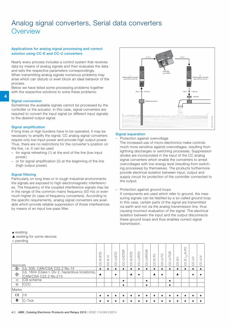
Nearly every process includes a control system that receives data by means of analog signals and then evaluates the data and sets the respective parameters correspondingly. When transmitting analog signals numerous problems may arise which can disturb or even block an ideal behavior of the process.Below we have listed some processing problems together with the respective solutions to solve these problems:
Signal conversionSometimes the available signals cannot be processed by the controller or the actuator. In this case, signal converters are required to convert the input signal (or different input signals) to the desired output signal.
Signal amplificationIf long lines or high burdens have to be operated, it may be necessary to amplify the signal. CC analog signal converters require only low input power and provide high output power. Thus, there are no restrictions for the converter's position on the line, i.e. it can be used – for signal refreshing (1) at the end of the line (low input
power) – or for signal amplification (2) at the beginning of the line
(high output power).
Signal filteringParticularly on long lines or in rough industrial environments the signals are exposed to high electromagnetic interferenc-es. The frequency of the coupled interference signals may be in the range of the common mains frequency (50 Hz) or even much higher (in case of frequency converters). According to the specific requirements, analog signal converters are avail-able which provide reliable suppression of those interferences by means of an input low-pass filter.
Signal separation – Protection against overvoltage
The increased use of micro-electronics make controls much more sensitive against overvoltages, resulting from lightning discharges or switching processes. Suppression diodes are incorporated in the input of the CC analog signal converters which enable the converters to arrest overvoltages with low energy level (resulting from switch-ing processes) by themselves. The products furthermore provide electrical isolation between input, output and supply circuit for protection of the controller connected to the output.
– Protection against ground loops If components are used which refer to ground, the mea-suring signals can be falsified by a so-called ground loop. In this case, certain parts of the signal are transmitted via earth and not via the analog transmission line, thus causing incorrect evaluation of the signal. The electrical isolation between the input and the output disconnects these ground loops and thus enables correct signal transmission.
J existing G existing for some devices j pending
Approvals CC
-E/S
TD
CC
-E I/
I
CC
-U/S
TD
CC
-U/S
TD
R
CC
-E/R
TD
CC
-U/R
TD
CC
-U/R
TD
R
CC
-E/T
C
CC
-U/T
C
CC
-U/T
CR
CC
-E/I
CC
-E I A
C/I
LPO
CC
-U/I
CC
-U/V
A UL 508, CAN/CSA C22.2 No.14 J J J J J J J J J J J J J J
AUL 1604 (Class I, Div 2, hazardous locations), CAN/CSA C22.2 No.213
G J G J G J G J J
K CB scheme J J JE CCC J J J
Marks
a CE J J J J J J J J J J J J J J
b C-Tick J J J J J J J J J J J J J J
0-10 V0-10 V
100 m 0-20 mA 100 m 4-20 mA
2CD
C 2
82 0
13 F
0206
Controllere.g. AC500
Measuring sensor
Actuator
1. Analog signal converter
(e.g. CC-E or CC-U)
2. Analog signal converter
(e.g. CC-E or CC-U)
4
2CDC 110 004 C0210 | Catalog Electronic Products and Relays 2015 | ABB 4/4
Analog signal converters, Serial data convertersOverview
RS-232
RS-232
RS-485
RS-485
RS-232
RS-232
RS-232
RS-232
RS-422 RS-422
RS-422 RS-422
RS-232 RS-232 RS-232 RS-232
RS-23215 m max.
1.2 km max.
1.2 km max.
15 mmax.
TCP RS-232 RS-485
Modbus / RTU
Modbus / TCP
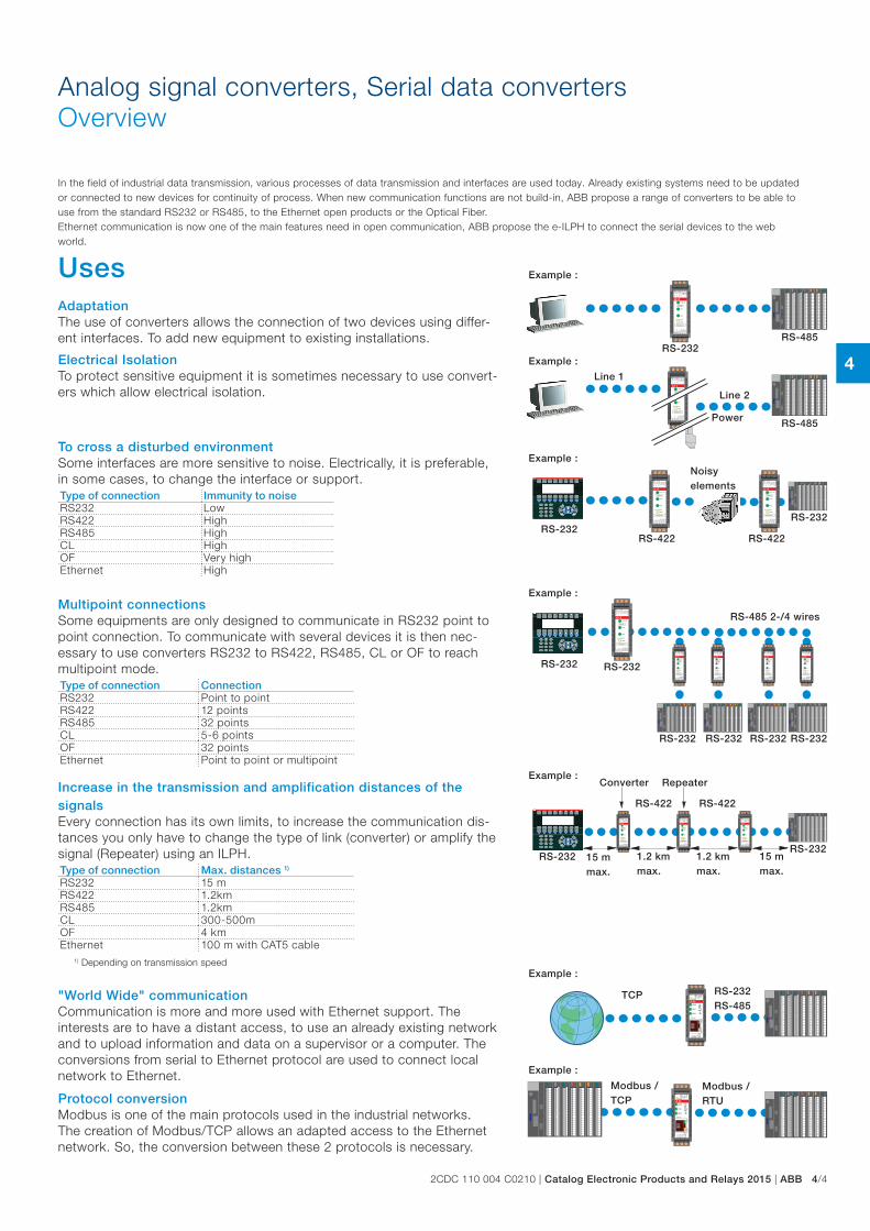
In the field of industrial data transmission, various processes of data transmission and interfaces are used today. Already existing systems need to be updated or connected to new devices for continuity of process. When new communication functions are not build-in, ABB propose a range of converters to be able to use from the standard RS232 or RS485, to the Ethernet open products or the Optical Fiber.Ethernet communication is now one of the main features need in open communication, ABB propose the e-ILPH to connect the serial devices to the web world.
Uses AdaptationThe use of converters allows the connection of two devices using differ-ent interfaces. To add new equipment to existing installations.
Electrical IsolationTo protect sensitive equipment it is sometimes necessary to use convert-ers which allow electrical isolation.
To cross a disturbed environmentSome interfaces are more sensitive to noise. Electrically, it is preferable, in some cases, to change the interface or support.Type of connection Immunity to noiseRS232 LowRS422 HighRS485 HighCL HighOF Very highEthernet High
Multipoint connectionsSome equipments are only designed to communicate in RS232 point to point connection. To communicate with several devices it is then nec-essary to use converters RS232 to RS422, RS485, CL or OF to reach multipoint mode.Type of connection ConnectionRS232 Point to pointRS422 12 pointsRS485 32 pointsCL 5-6 pointsOF 32 pointsEthernet Point to point or multipoint
Increase in the transmission and amplification distances of the signalsEvery connection has its own limits, to increase the communication dis-tances you only have to change the type of link (converter) or amplify the signal (Repeater) using an ILPH.Type of connection Max. distances 1)
RS232 15 mRS422 1.2kmRS485 1.2kmCL 300-500mOF 4 kmEthernet 100 m with CAT5 cable
1) Depending on transmission speed
Example :
Example :
Example :
Example :
Example :
Example :
Example :
Line 1
Line 2
Power
Converter Repeater
Noisy elements
RS-485 2-/4 wires
"World Wide" communicationCommunication is more and more used with Ethernet support. The interests are to have a distant access, to use an already existing network and to upload information and data on a supervisor or a computer. The conversions from serial to Ethernet protocol are used to connect local network to Ethernet.
Protocol conversionModbus is one of the main protocols used in the industrial networks. The creation of Modbus/TCP allows an adapted access to the Ethernet network. So, the conversion between these 2 protocols is necessary.
4
4/5 ABB | Catalog Electronic Products and Relays 2015 | 2CDC 110 004 C0210
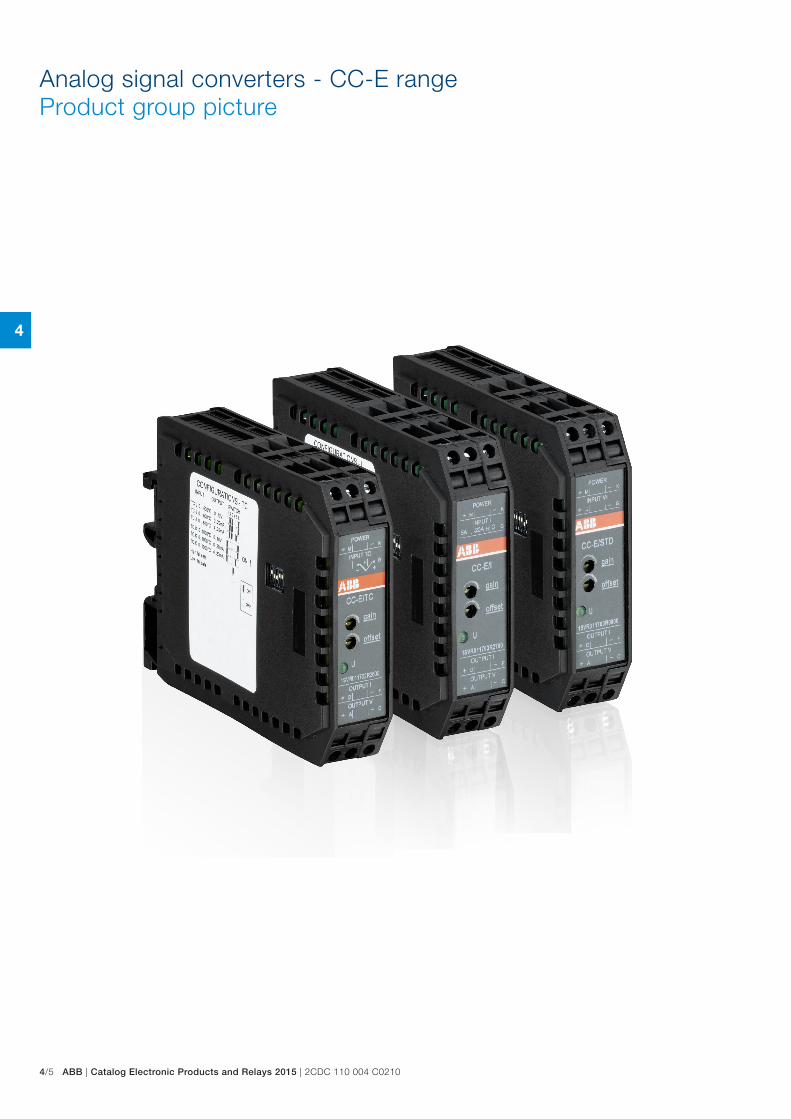
Analog signal converters - CC-E rangeProduct group picture
4
2CDC 110 004 C0210 | Catalog Electronic Products and Relays 2015 | ABB 4/6
Analog signal converters - CC-E rangeTable of contents
Analog signal converters - CC-E range
Benefits and advantages 4/7
Ordering details - Standard signal converters 4/8
Ordering details - RTD converters 4/9
Ordering details - Thermocouple converters 4/10
Ordering details - Measuring converters 4/11
DIP switch settings, Dimensional drawings 4/12
Wiring instructions 4/13
Technical data 4/14
Technical data 4/15
Technical data 4/16
4
4/7 ABB | Catalog Electronic Products and Relays 2015 | 2CDC 110 004 C0210
Analog signal converters - CC-E rangeBenefits and advantages
CC-E/STD analog signal converter with 3-way electrical isolation – 2 universally configurable devices (type CC-E/STD) – 2x10 single-function devices – "Plug and Work", no adjustment of single-function devices
required
CC-E/RTD temperature signal converter for RTD sensors, linearized with 3-way electrical isolation – 2 universally configurable devices (type CC-E/RTD) – 2x12 single-function devices – Plug and Work", no adjustment of single-function devices
required – Temperature signal converter for PT100 sensors – 2- or 3-wire connection
CC-E/TC analog signal converter for thermocouple signals of the types J and K with 3-way electrical isolation – 2 universally configurable devices (type CC-E/TC) – 2x6 single-function devices – "Plug and Work", no adjustment of single-function devices
required – Integrated cold-junction compensation
CC-E/I measuring converter for current signals 0-5 A, 0-20 A, AC/DC with 3-way electrical isolation – 2 universally configurable devices (type CC-E/I) – 2x6 single-function devices – "Plug and Work", no adjustment of single-function devices
required
CC-E IAC/ILPO measuring converter without auxiliary power for sinusoidal currents 0-1 A, 0-5 A, output 4-20 mA – Measuring converter for sinusoidal currents (0-1 A, 0-5 A) – Measuring range selection by front-face sliding switch – 4-20 mA output current in proportion to input current – no additional power supply required
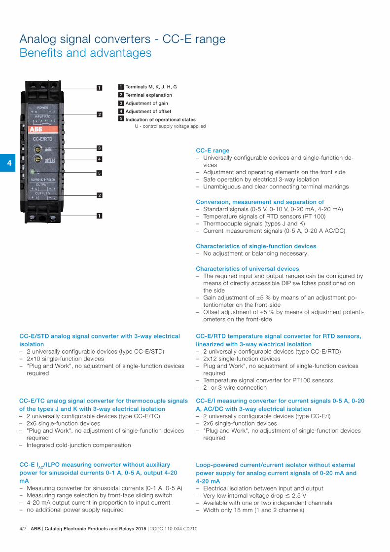
CC-E range – Universally configurable devices and single-function de-
vices – Adjustment and operating elements on the front side – Safe operation by electrical 3-way isolation – Unambiguous and clear connecting terminal markings
Conversion, measurement and separation of – Standard signals (0-5 V, 0-10 V, 0-20 mA, 4-20 mA) – Temperature signals of RTD sensors (PT 100) – Thermocouple signals (types J and K) – Current measurement signals (0-5 A, 0-20 A AC/DC)
Characteristics of single-function devices – No adjustment or balancing necessary.
Characteristics of universal devices – The required input and output ranges can be configured by
means of directly accessible DIP switches positioned on the side
– Gain adjustment of ±5 % by means of an adjustment po-tentiometer on the front-side
– Offset adjustment of ±5 % by means of adjustment potenti-ometers on the front-side
Loop-powered current/current isolator without external power supply for analog current signals of 0-20 mA and 4-20 mA – Electrical isolation between input and output – Very low internal voltage drop 2.5 V – Available with one or two independent channels – Width only 18 mm (1 and 2 channels)
4
1
1
2
2
3
5
1 Terminals M, K, J, H, G
2 Terminal explanation
3 Adjustment of gain
4 Adjustment of offset
4 Indication of operational states U - control supply voltage applied
4
2CDC 110 004 C0210 | Catalog Electronic Products and Relays 2015 | ABB 4/8
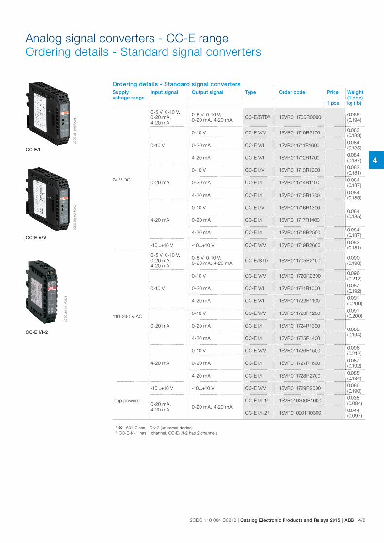
Analog signal converters - CC-E rangeOrdering details - Standard signal converters
1) B 1604 Class I, Div.2 (universal device)2) CC-E-I/I-1 has 1 channel, CC-E-I/I-2 has 2 channels
Ordering details - Standard signal convertersSupply voltage range
Input signal Output signal Type Order code Price
1 pce
Weight(1 pce)kg (lb)
24 V DC
0-5 V, 0-10 V, 0-20 mA, 4-20 mA
0-5 V, 0-10 V, 0-20 mA, 4-20 mA CC-E/STD1) 1SVR011700R0000 0.088
(0.194)
0-10 V
0-10 V CC-E V/V 1SVR011710R2100 0.083 (0.183)
0-20 mA CC-E V/I 1SVR011711R1600 0.084 (0.185)
4-20 mA CC-E V/I 1SVR011712R1700 0.084 (0.187)
0-20 mA
0-10 V CC-E I/V 1SVR011713R1000 0.082 (0.181)
0-20 mA CC-E I/I 1SVR011714R1100 0.084 (0.187)
4-20 mA CC-E I/I 1SVR011715R1200 0.084 (0.185)
4-20 mA
0-10 V CC-E I/V 1SVR011716R13000.084 (0.185)
0-20 mA CC-E I/I 1SVR011717R1400
4-20 mA CC-E I/I 1SVR011718R2500 0.084 (0.187)
-10...+10 V -10...+10 V CC-E V/V 1SVR011719R2600 0.082 (0.181)
110-240 V AC
0-5 V, 0-10 V, 0-20 mA, 4-20 mA
0-5 V, 0-10 V, 0-20 mA, 4-20 mA CC-E/STD 1SVR011705R2100 0.090
(0.198)
0-10 V
0-10 V CC-E V/V 1SVR011720R2300 0.096 (0.212)
0-20 mA CC-E V/I 1SVR011721R1000 0.087 (0.192)
4-20 mA CC-E V/I 1SVR011722R1100 0.091 (0.200)
0-20 mA
0-10 V CC-E V/V 1SVR011723R1200 0.091 (0.200)
0-20 mA CC-E I/I 1SVR011724R13000.088 (0.194)
4-20 mA CC-E I/I 1SVR011725R1400
4-20 mA
0-10 V CC-E V/V 1SVR011726R1500 0.096 (0.212)
0-20 mA CC-E I/I 1SVR011727R1600 0.087 (0.192)
4-20 mA CC-E I/I 1SVR011728R2700 0.088 (0.194)
loop powered
-10...+10 V -10...+10 V CC-E V/V 1SVR011729R2000 0.086 (0.190)
0-20 mA, 4-20 mA 0-20 mA, 4-20 mA
CC-E I/I-12) 1SVR010200R1600 0.038 (0.084)
CC-E I/I-22) 1SVR010201R0300 0.044 (0.097)
2CD
C 2
81 0
10 F
0003
2CD
C 2
81 0
01 F
0003
2CD
C 2
81 0
41 F
0003
CC-E/I
CC-E V/V
CC-E I/I-2
4
4/9 ABB | Catalog Electronic Products and Relays 2015 | 2CDC 110 004 C0210
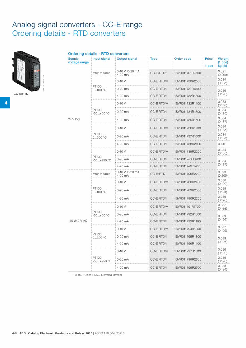
Analog signal converters - CC-E rangeOrdering details - RTD converters
2CD
C 2
81 0
04 F
0003
CC-E/RTD
Ordering details - RTD convertersSupply voltage range
Input signal Output signal Type Order code Price
1 pce
Weight(1 pce)kg (lb)
24 V DC
refer to table 0-10 V, 0-20 mA, 4-20 mA CC-E/RTD1) 1SVR011701R2500 0.091
(0.200)
PT100 0...100 °C
0-10 V CC-E RTD/V 1SVR011730R2500 0.084 (0.185)
0-20 mA CC-E RTD/I 1SVR011731R1200 0.086 (0.190)4-20 mA CC-E RTD/I 1SVR011732R1300
PT100 -50...+50 °C
0-10 V CC-E RTD/V 1SVR011733R1400 0.083 (0.183)
0-20 mA CC-E RTD/I 1SVR011734R1500 0.084 (0.185)
4-20 mA CC-E RTD/I 1SVR011735R1600 0.084 (0.187)
PT100 0...300 °C
0-10 V CC-E RTD/V 1SVR011736R1700 0.084 (0.185)
0-20 mA CC-E RTD/I 1SVR011737R1000 0.084 (0.187)
4-20 mA CC-E RTD/I 1SVR011738R2100 0.101
PT100 -50...+250 °C
0-10 V CC-E RTD/V 1SVR011739R2200 0.084 (0.185)
0-20 mA CC-E RTD/I 1SVR011740R0700 0.084 (0.187)4-20 mA CC-E RTD/I 1SVR011741R2400
110-240 V AC
refer to table 0-10 V, 0-20 mA, 4-20 mA CC-E/RTD 1SVR011706R2200 0.093
(0.205)
PT100 0...100 °C
0-10 V CC-E RTD/V 1SVR011788R2400 0.086 (0.190)
0-20 mA CC-E RTD/I 1SVR011789R2500 0.088 (0.194)
4-20 mA CC-E RTD/I 1SVR011790R2200 0.089 (0.196)
PT100 -50...+50 °C
0-10 V CC-E RTD/V 1SVR011791R1700 0.087 (0.192)
0-20 mA CC-E RTD/I 1SVR011792R1000 0.089 (0.196)4-20 mA CC-E RTD/I 1SVR011793R1100
PT100 0...300 °C
0-10 V CC-E RTD/V 1SVR011794R1200 0.087 (0.192)
0-20 mA CC-E RTD/I 1SVR011795R1300 0.089 (0.196)4-20 mA CC-E RTD/I 1SVR011796R1400
PT100 -50...+250 °C
0-10 V CC-E RTD/V 1SVR011797R1500 0.086 (0.190)
0-20 mA CC-E RTD/I 1SVR011798R2600 0.089 (0.196)
4-20 mA CC-E RTD/I 1SVR011799R2700 0.088 (0.194)
1) B 1604 Class I, Div.2 (universal device)
4
2CDC 110 004 C0210 | Catalog Electronic Products and Relays 2015 | ABB 4/10
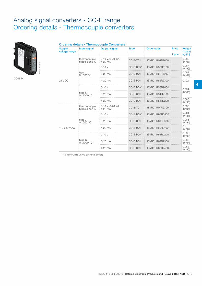
Analog signal converters - CC-E rangeOrdering details - Thermocouple converters
2CD
C 2
81 0
07 F
0003
CC-E TC
Ordering details - Thermocouple ConvertersSupply voltage range
Input signal Output signal Type Order code Price
1 pce
Weight(1 pce)kg (lb)
24 V DC
thermocouple types J and K
0-10 V, 0-20 mA, 4-20 mA CC-E/TC1) 1SVR011702R2600 0.089
(0.196)
type J 0...600 °C
0-10 V CC-E TC/V 1SVR011750R0100 0.087 (0.192)
0-20 mA CC-E TC/I 1SVR011751R2600 0.084 (0.187)
4-20 mA CC-E TC/I 1SVR011752R2700 0.102
type K 0...1000 °C
0-10 V CC-E TC/V 1SVR011753R20000.084 (0.185)
0-20 mA CC-E TC/I 1SVR011754R2100
4-20 mA CC-E TC/I 1SVR011755R2200 0.086 (0.190)
110-240 V AC
thermocouple types J and K
0-10 V, 0-20 mA, 4-20 mA CC-E/TC 1SVR011707R2300 0.088
(0.194)
type J 0...600 °C
0-10 V CC-E TC/V 1SVR011760R0300 0.084 (0.187)
0-20 mA CC-E TC/I 1SVR011761R2000 0.088 (0.194)
4-20 mA CC-E TC/I 1SVR011762R2100 0.1 (0.220)
type K 0...1000 °C
0-10 V CC-E TC/V 1SVR011763R2200 0.086 (0.190)
0-20 mA CC-E TC/I 1SVR011764R2300 0.088 (0.194)
4-20 mA CC-E TC/I 1SVR011765R2400 0.086 (0.190)
1) B 1604 Class I, Div.2 (universal device)
4
4/11 ABB | Catalog Electronic Products and Relays 2015 | 2CDC 110 004 C0210
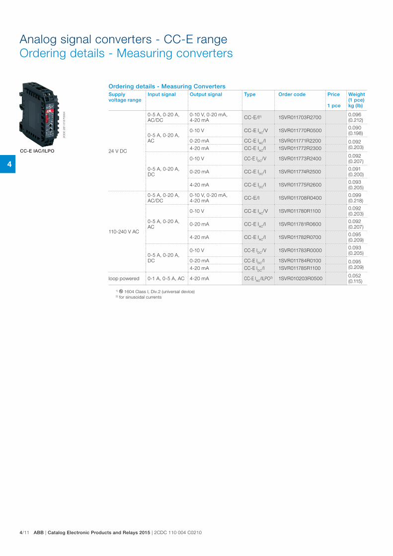
Ordering details - Measuring ConvertersSupply voltage range
Input signal Output signal Type Order code Price
1 pce
Weight(1 pce)kg (lb)
24 V DC
0-5 A, 0-20 A, AC/DC
0-10 V, 0-20 mA, 4-20 mA CC-E/I1) 1SVR011703R2700 0.096
(0.212)
0-5 A, 0-20 A, AC
0-10 V CC-E IAC/V 1SVR011770R0500 0.090 (0.198)
0-20 mA CC-E IAC/I 1SVR011771R2200 0.092 (0.203)4-20 mA CC-E IAC/I 1SVR011772R2300
0-5 A, 0-20 A, DC
0-10 V CC-E IDC/V 1SVR011773R2400 0.092 (0.207)
0-20 mA CC-E IDC/I 1SVR011774R2500 0.091 (0.200)
4-20 mA CC-E IDC/I 1SVR011775R2600 0.093 (0.205)
110-240 V AC
0-5 A, 0-20 A, AC/DC
0-10 V, 0-20 mA, 4-20 mA CC-E/I 1SVR011708R0400 0.099
(0.218)
0-5 A, 0-20 A, AC
0-10 V CC-E IAC/V 1SVR011780R1100 0.092 (0.203)
0-20 mA CC-E IAC/I 1SVR011781R0600 0.092 (0.207)
4-20 mA CC-E IAC/I 1SVR011782R0700 0.095 (0.209)
0-5 A, 0-20 A, DC
0-10 V CC-E IDC/V 1SVR011783R0000 0.093 (0.205)
0-20 mA CC-E IDC/I 1SVR011784R0100 0.095 (0.209)4-20 mA CC-E IDC/I 1SVR011785R1100
loop powered 0-1 A, 0-5 A, AC 4-20 mA CC-E IAC/ILPO2) 1SVR010203R0500 0.052 (0.115)
2CD
C 2
81 0
18 F
0004
CC-E IAC/ILPO
1) B 1604 Class I, Div.2 (universal device)2) for sinusoidal currents
Analog signal converters - CC-E rangeOrdering details - Measuring converters
4
2CDC 110 004 C0210 | Catalog Electronic Products and Relays 2015 | ABB 4/12
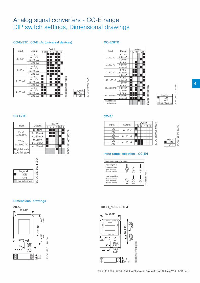
Analog signal converters - CC-E rangeDIP switch settings, Dimensional drawings
81 2 43 5 6 7
0...5 V
0...10 V
0...20 mA
4...20 mA
0...5 V0...10 V
0...20 mA4...20 mA
0...5 V0...10 V
0...20 mA4...20 mA
0...5 V0...10 V
0...20 mA4...20 mA
0...5 V0...10 V
0...20 mA4...20 mA 2C
DC
282
001
F02
04
Input OutputSwitch
2CD
C 2
82 0
02 F
0204
ONLegend
OFF
CC-E/STD, CC-E x/x (universal devices)
2CD
C 2
82 0
03 F
0204
OFF
Legend
no influence
ON
1 2 43 5 6
0...300 °C
0...100 °C
0...500 °C
-50...+50 °C
-50...+250 °C
-50...+450 °C
High fail safeLow fail safe
0...10 V0-20 mA4-20 mA0-10 V
0-20 mA4-20 mA0-10 V
0-20 mA4-20 mA0-10 V
0-20 mA4-20 mA0-10 V
0-20 mA4-20 mA0-10 V
0-20 mA4-20 mA
2CD
C 2
82 0
06 F
0208
Input OutputSwitch
CC-E/RTD
2CD
C 2
82 0
03 F
0204
OFF
Legend
no influence
ON
1 2 43 5 6
TC-J: 0...600 °C
TC-K:0...1000 °C
High fail safeLow fail safe
0...10 V0...20 mA4...20 mA0...10 V
0...20 mA4...20 mA
2CD
C 2
82 0
07 F
0208
Input OutputSwitch
CC-E/TC CC-E/I
Dimensional drawings
2CD
C 2
82 0
02 F
0204
ONLegend
OFF
1 2 43 5 6
I - DCI - AC
I - AC
I - DCI - ACI - DC
0...10 V
0...20 mA
4...20 mA
2CD
C 2
82 0
05 F
0208Input Output
Switch
2CD
C 2
82 0
11 F
0204
Select input range by terminals
Input range 5 A
Connected linesUsed terminalsTerminal marking
Input range 20 A
Connected linesUsed terminalsTerminal marking
Input range selection - CC-E/I
CC-E/x CC-E IAC/ILPO, CC-E I/I
22.50,88 " 2C
DC
282
011
F0b
06
180.71" 2C
DC
282
012
F0b
06
4
4/13 ABB | Catalog Electronic Products and Relays 2015 | 2CDC 110 004 C0210
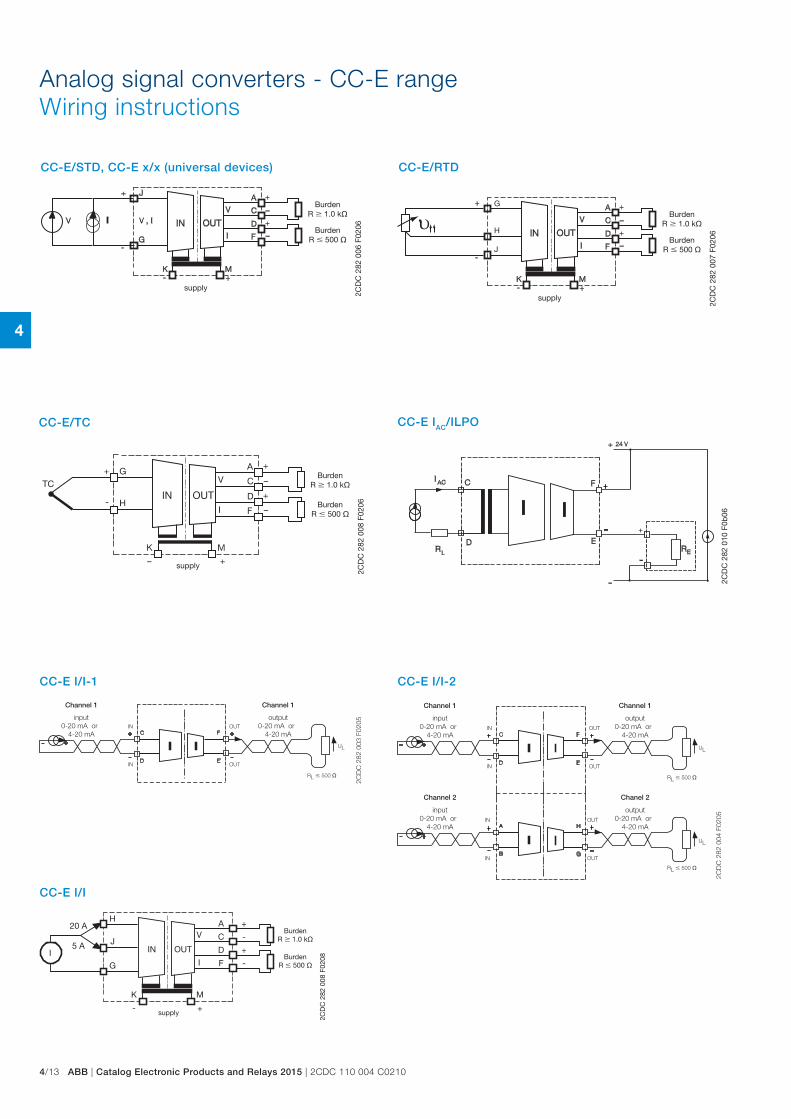
CC-E/STD, CC-E x/x (universal devices)
2CD
C 2
82 0
06 F
0206
BurdenR 1.0 k
BurdenR 500
supply
CC-E/RTD
J
H
G
2CD
C 2
82 0
07 F
0206
BurdenR 1.0 k
BurdenR 500
supply
CC-E/TC
2CD
C 2
82 0
08 F
0206
BurdenR 1.0 k
BurdenR 500
supply
RL 500
UL
C
D
F
E
IN
IN
OUT
OUT
2CD
C 2
82 0
03 F
0205
Channel 1
input0-20 mA or
4-20 mA
Channel 1
output0-20 mA or
4-20 mA
J
H
G
20 A
5 A
A
C
D
F
V
I
K
-
M
+
+
-
+
-
IN OUTI
2CD
C 2
82 0
08 F
0208
BurdenR 1.0 k
BurdenR 500
supply
RL 500
RL 500
UL
UL
C
D
F
E
A
B
H
G
IN
IN
IN
IN
OUT
OUT
OUT
OUT
2CD
C 2
82 0
04 F
0205
Channel 1
input0-20 mA or
4-20 mA
Channel 2
input0-20 mA or
4-20 mA
Channel 1
output0-20 mA or
4-20 mA
Chanel 2
output0-20 mA or
4-20 mA
CC-E I/I-1
CC-E I/I
2CD
C 2
82 0
10 F
0b06
CC-E IAC/ILPO
Analog signal converters - CC-E rangeWiring instructions
CC-E I/I-2
4
2CDC 110 004 C0210 | Catalog Electronic Products and Relays 2015 | ABB 4/14
Analog signal converters - CC-E rangeTechnical data
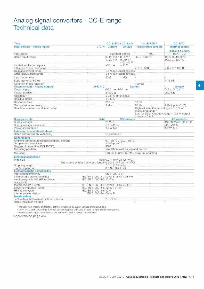
Type CC-E/STD / CC-E x/x CC-E/RTD 3) CC-E/TCInput circuits - Analog inputs J-G-H Current Voltage Temperature sensors Thermocouples
(IEC 584-1 and 2)Input signal Standard signals PT100 TC.K, TC.JRated input range 0...20 mA /
4...20 mA0...5 V /0...10 V /-10...+10 V
-50...+500 °C TC.K: 0...1000 °C, TC.J: 0...600 °C
Limitation of input signals +55 mA ± 11 VInfluence of line resistance - < 0.01 %/ < 0.5 % / 100 Gain adjustment range ± 5 % (universal devices)Offset adjustment range ± 5 % (universal devices)Input impedance 50 1 M - -Suppression at 50 Hz - - > 35 dBCommon-mode rejection - 100 dBOutput circuits - Analog outputs D-F, A-C Current VoltageOutput signal 0-20 mA, 4-20 mA 0-5 V, 0-10 VOutput burden 500 1.0 KAccuracy 1) ± 0.5 % of full-scaleResidual ripple < 0.5 %Response time 200 µs 10 msTransmission frequency 2 kHz 80 Hz 2 Hz (up to -3 dB)Reaction to input circuit interruption High fail safe: Output voltage > 115 % of
measuring range 2) Low fail safe: Output voltage < -0.6 V, output current = 0 mA
Supply circuits K-M DC versions AC versionsSupply voltage 24 V DC 110-240 V AC - 50/60 HzSupply voltage tolerance -15...+15 % -15...+10 %Power consumption 1.5 W typ. 1.5 VA typ.Indication of operational statesRated control supply voltage US U: green LED
General dataAmbient temperature range operation / storage 0...+60 °C / -20...+80 °CTemperature coefficient ± 500 ppm/°CDegree of protection (DIN 40050) IP20Mounting position ventilation slots on top and bottom
Mounting DIN rail (IEC/EN 60715), snap-on mounting
Electrical connectionWire size rigid 0.2-4 mm2 (24-12 AWG)
fine-strand with(out) wire end ferrule 0.2-2.5 mm2 (24-14 AWG)Stripping length 7 mm (0.28 inch)Tightening torque 0.5 Nm (4.4 lb.in)Electromagnetic compatibilityInterference immunity EN 61000-6-2electrostatic discharge (ESD) IEC/EN 61000-4-2 Level 3 (±6 kV / ±8 kV)electromagnetic field(HF radiation resistance)
IEC/EN 61000-4-3 10 V/m
fast transients (Burst) IEC/EN 61000-4-4 Level 3 (±2 kV / 5 kH)powerful impulses (Surge) IEC/EN 61000-4-5 ±2 kV / ±1 kVHF line emission IEC/EN 61000-4-6 10 VInterference emission EN 61000-6-4 Class BIsolation dataTest voltage between all isolated circuits 2.5 kV ACRated insulation voltage - - -
1) Includes non-linearity and factory setting, influenced by supply voltage and output load.2) Only -/RTD and -/TC: Single-function devices respond with Low fail safe to input signal interruptions.3) When connecting a 2-wire sensor, the terminals J and H have to be jumpered.
Approvals on page 4/4.
4
4/15 ABB | Catalog Electronic Products and Relays 2015 | 2CDC 110 004 C0210
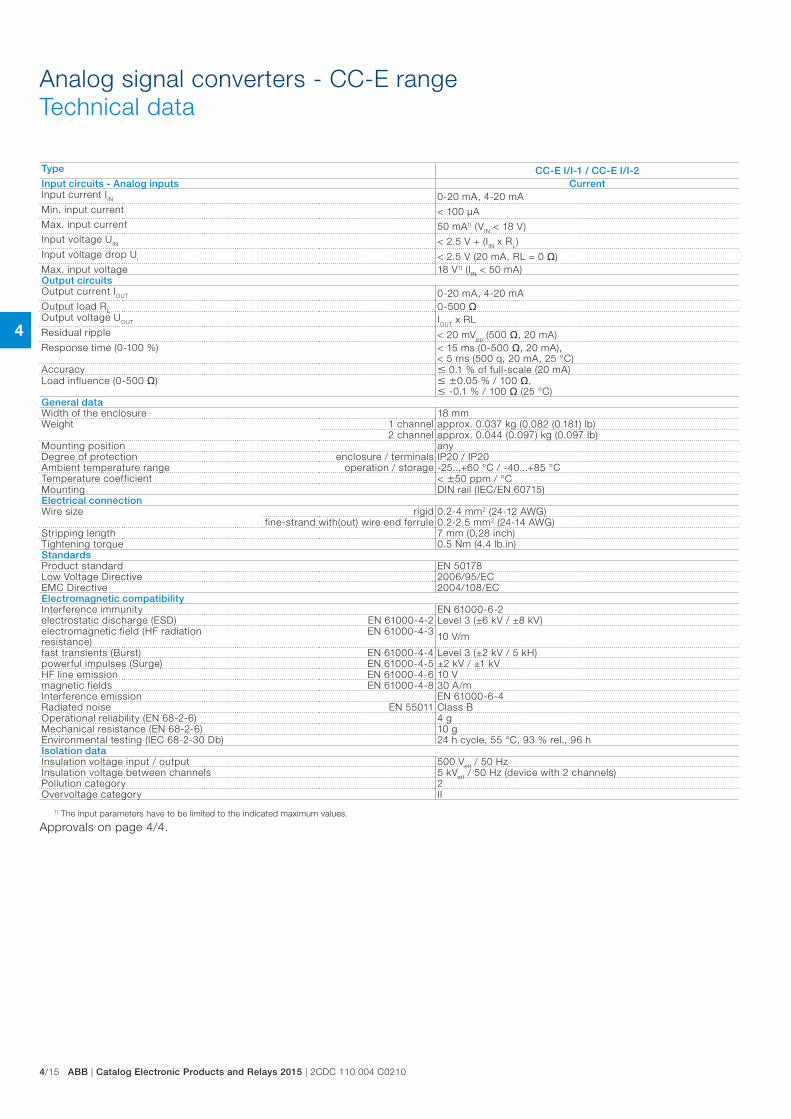
Type CC-E I/I-1 / CC-E I/I-2Input circuits - Analog inputs CurrentInput current IIN 0-20 mA, 4-20 mAMin. input current < 100 µAMax. input current 50 mA1) (VIN < 18 V)Input voltage UIN < 2.5 V + (IIN x RL)Input voltage drop Ui < 2.5 V (20 mA, RL = 0 )Max. input voltage 18 V1) (IIN < 50 mA)Output circuitsOutput current IOUT 0-20 mA, 4-20 mAOutput load RL 0-500 Output voltage UOUT IOUT x RLResidual ripple < 20 mVpp (500 , 20 mA)Response time (0-100 %) < 15 ms (0-500 , 20 mA),
< 5 ms (500 q, 20 mA, 25 °C)Accuracy 0.1 % of full-scale (20 mA)Load influence (0-500 ) 0.05 % / 100 ,
-0.1 % / 100 (25 °C)General dataWidth of the enclosure 18 mmWeight 1 channel approx. 0.037 kg (0.082 (0.181) lb)
2 channel approx. 0.044 (0.097) kg (0.097 lb)Mounting position anyDegree of protection enclosure / terminals IP20 / IP20Ambient temperature range operation / storage -25...+60 °C / -40...+85 °CTemperature coefficient < 50 ppm / °CMounting DIN rail (IEC/EN 60715)Electrical connectionWire size rigid 0.2-4 mm2 (24-12 AWG)
fine-strand with(out) wire end ferrule 0.2-2.5 mm2 (24-14 AWG)Stripping length 7 mm (0,28 inch)Tightening torque 0.5 Nm (4.4 lb.in)StandardsProduct standard EN 50178Low Voltage Directive 2006/95/ECEMC Directive 2004/108/ECElectromagnetic compatibility Interference immunity EN 61000-6-2electrostatic discharge (ESD) EN 61000-4-2 Level 3 (±6 kV / ±8 kV)electromagnetic field (HF radiation resistance)
EN 61000-4-3 10 V/m
fast transients (Burst) EN 61000-4-4 Level 3 (±2 kV / 5 kH)powerful impulses (Surge) EN 61000-4-5 ±2 kV / ±1 kVHF line emission EN 61000-4-6 10 Vmagnetic fields EN 61000-4-8 30 A/mInterference emission EN 61000-6-4Radiated noise EN 55011 Class BOperational reliability (EN 68-2-6) 4 gMechanical resistance (EN 68-2-6) 10 gEnvironmental testing (IEC 68-2-30 Db) 24 h cycle, 55 °C, 93 % rel., 96 hIsolation dataInsulation voltage input / output 500 Veff / 50 HzInsulation voltage between channels 5 kVeff / 50 Hz (device with 2 channels)Pollution category 2Overvoltage category II
1) The input parameters have to be limited to the indicated maximum values.
Approvals on page 4/4.
Analog signal converters - CC-E rangeTechnical data
4
2CDC 110 004 C0210 | Catalog Electronic Products and Relays 2015 | ABB 4/16
Analog signal converters - CC-E rangeTechnical data
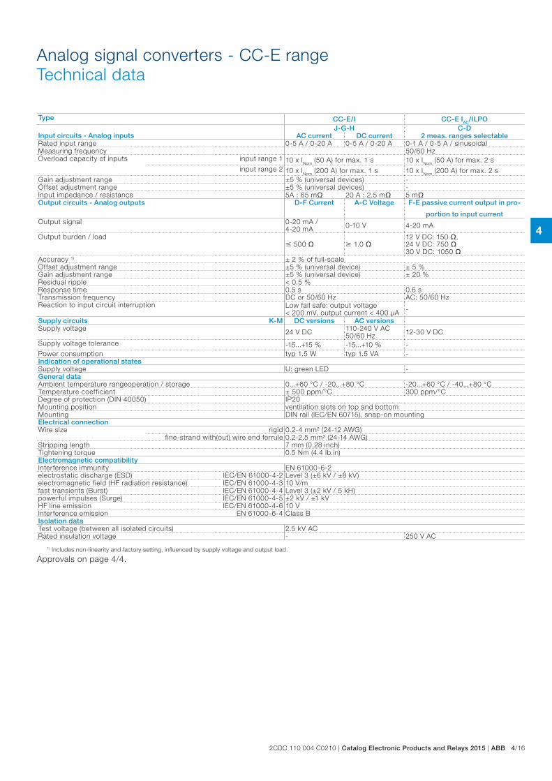
Type CC-E/I CC-E IAC/ILPO Input circuits - Analog inputs
J-G-H C-DAC current DC current 2 meas. ranges selectable
Rated input range 0-5 A / 0-20 A 0-5 A / 0-20 A 0-1 A / 0-5 A / sinusoidalMeasuring frequency 50/60 HzOverload capacity of inputs input range 1 10 x INom (50 A) for max. 1 s 10 x INom (50 A) for max. 2 s
input range 2 10 x INom (200 A) for max. 1 s 10 x INom (200 A) for max. 2 sGain adjustment range ±5 % (universal devices) -Offset adjustment range ±5 % (universal devices) -Input impedance / resistance 5A : 65 m 20 A : 2.5 m 5 mOutput circuits - Analog outputs D-F Current A-C Voltage F-E passive current output in pro-
portion to input currentOutput signal 0-20 mA /
4-20 mA 0-10 V 4-20 mA
Output burden / load 500 1.0
12 V DC: 150 , 24 V DC: 750 30 V DC: 1050
Accuracy 1) ± 2 % of full-scaleOffset adjustment range ±5 % (universal device) ± 5 %Gain adjustment range ±5 % (universal device) ± 20 %Residual ripple < 0.5 %Response time 0.5 s 0.6 sTransmission frequency DC or 50/60 Hz AC: 50/60 HzReaction to input circuit interruption Low fail safe: output voltage
< 200 mV, output current < 400 µA -
Supply circuits K-M DC versions AC versionsSupply voltage 24 V DC 110-240 V AC
50/60 Hz 12-30 V DC
Supply voltage tolerance -15...+15 % -15...+10 % -Power consumption typ 1.5 W typ 1.5 VA -Indication of operational statesSupply voltage U: green LED -General dataAmbient temperature range operation / storage 0...+60 °C / -20...+80 °C -20...+60 °C / -40...+80 °CTemperature coefficient ± 500 ppm/°C 300 ppm/°CDegree of protection (DIN 40050) IP20Mounting position ventilation slots on top and bottomMounting DIN rail (IEC/EN 60715), snap-on mountingElectrical connectionWire size rigid 0.2-4 mm² (24-12 AWG)
fine-strand with(out) wire end ferrule 0.2-2.5 mm² (24-14 AWG)Stripping length 7 mm (0.28 inch)Tightening torque 0.5 Nm (4.4 lb.in)Electromagnetic compatibilityInterference immunity EN 61000-6-2electrostatic discharge (ESD) IEC/EN 61000-4-2 Level 3 (±6 kV / ±8 kV)electromagnetic field (HF radiation resistance) IEC/EN 61000-4-3 10 V/mfast transients (Burst) IEC/EN 61000-4-4 Level 3 (±2 kV / 5 kH)powerful impulses (Surge) IEC/EN 61000-4-5 ±2 kV / ±1 kVHF line emission IEC/EN 61000-4-6 10 VInterference emission EN 61000-6-4 Class BIsolation dataTest voltage (between all isolated circuits) 2.5 kV ACRated insulation voltage - 250 V AC
1) Includes non-linearity and factory setting, influenced by supply voltage and output load.
Approvals on page 4/4.
4
4/17 ABB | Catalog Electronic Products and Relays 2015 | 2CDC 110 004 C0210
Analog signal converters - CC-U rangeProduct group picture
4
2CDC 110 004 C0210 | Catalog Electronic Products and Relays 2015 | ABB 4/18
Analog signal converters - CC-U rangeTable of contents
Analog signal converters - CC-U range
Overview 4/19
Ordering details 4/21
Ordering details - Accessories 4/22
DIP switch settings 4/23
Wiring instructions 4/25
Technical information 4/26
Technical data 4/29
Technical diagr., Connection diagr., Dimensional drawings 4/32
4
4/19 ABB | Catalog Electronic Products and Relays 2015 | 2CDC 110 004 C0210
Analog signal converters - CC-U rangeOverview
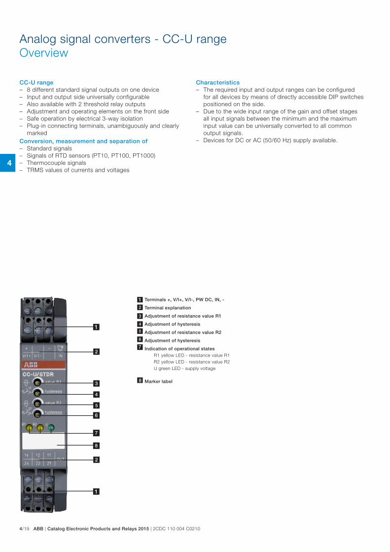
CC-U range – 8 different standard signal outputs on one device – Input and output side universally configurable – Also available with 2 threshold relay outputs – Adjustment and operating elements on the front side – Safe operation by electrical 3-way isolation – Plug-in connecting terminals, unambiguously and clearly
markedConversion, measurement and separation of – Standard signals – Signals of RTD sensors (PT10, PT100, PT1000) – Thermocouple signals – TRMS values of currents and voltages
Characteristics – The required input and output ranges can be configured
for all devices by means of directly accessible DIP switches positioned on the side.
– Due to the wide input range of the gain and offset stages all input signals between the minimum and the maximum input value can be universally converted to all common output signals.
– Devices for DC or AC (50/60 Hz) supply available.
4
1
1
2
2
3
5
1 Terminals +, V/I+, V/I-, PW DC, IN, -
2 Terminal explanation
3 Adjustment of resistance value R1
4 Adjustment of hysteresis
4 Adjustment of resistance value R2
Adjustment of hysteresis7 Indication of operational states
R1 yellow LED - resistance value R1 R2 yellow LED - resistance value R2 U green LED - supply voltage
8 Marker label
7
8
4
2CDC 110 004 C0210 | Catalog Electronic Products and Relays 2015 | ABB 4/20
Analog signal converters - CC-U rangeOverview
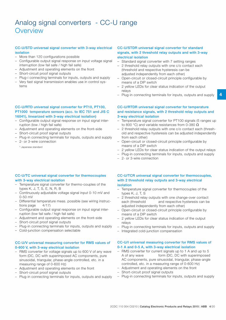
CC-U/STD universal signal converter with 3-way electrical isolation – More than 120 configurations possible – Configurable output signal response on input voltage signal
interruption (low fail safe / high fail safe) – Adjustment and operating elements on the front – Short-circuit proof signal outputs – Plug-i connecting terminals for inputs, outputs and supply – Very fast signal transmission enables use in control sys-
tems
CC-U/STDR universal signal converter for standard signals, with 2 threshold relay outputs and with 3-way electrical isolation – Standard signal converter with 7 setting ranges – 2 threshold relay outputs with one c/o contact each
(threshold and respective hysteresis can be adjusted independently from each other)
– Open-circuit or closed-circuit principle configurable by means of a DIP switch
– 2 yellow LEDs for clear status indication of the output relays
– Plug-in connecting terminals for inputs, outputs and supply
CC-U/RTD universal signal converter for PT10, PT100, PT1000 temperature sensors (acc. to IEC 751 and JIS C 16041), linearized with 3-way electrical isolation) – Configurable output signal response on input signal inter-
ruption (low / high fail safe) – Adjustment and operating elements on the front-side – Short-circuit proof signal outputs – Plug-in connecting terminals for inputs, outputs and supply – 2- or 3-wire connection
CC-U/RTDR universal signal converter for temperature and resistance signals, with 2 threshold relay outputs and 3-way electrical isolation – Temperature signal converter for PT100 signals (5 ranges up
to 800 °C) and variable resistances from 0-380 – 2 threshold relay outputs with one c/o contact each (thresh-
old and respective hysteresis can be adjusted independently from each other)
– Open-circuit or closed-circuit principle configurable by means of a DIP switch
– 2 yellow LEDs for clear status indication of the output relays – Plug-in connecting terminals for inputs, outputs and supply – 2- or 3-wire connection
CC-U/TC universal signal converter for thermocouples with 3-way electrical isolation – Temperature signal converter for thermo-couples of the
types K, J, T, S, E, N, R, B – Continuously adjustable voltage signal input 0-10 mV and
0-50 mV – Differential temperature meas. possible (see wiring instruc-
tions page 4/17) – Configurable output signal response on input signal inter-
ruption (low fail safe / high fail safe) – Adjustment and operating elements on the front-side – Short-circuit proof signal outputs – Plug-in connecting terminals for inputs, outputs and supply – Cold-junction compensation selectable
CC-U/TCR universal signal converter for thermocouples, with 2 threshold relay outputs and 3-way electrical isolation – Temperature signal converter for thermocouples of the
types K, J, T, S – 2 threshold relay outputs with one change-over contact
each (threshold and respective hysteresis can be adjusted independently from each other)
– Open-circuit or closed-circuit principle configurable by means of a DIP switch
– 2 yellow LEDs for clear status indication of the output relays
– Plug-in connecting terminals for inputs, outputs and supply – Integrated cold-junction compensation
CC-U/I universal measuring converter for RMS values of 0-1 A and 0-5 A, with 3-way electrical isolation – RMS converter for current signals up to 1 A and up to 5
A of any wave form (DC, DC with superimposed AC components, pure sinusoidal, triangular, phase-angle controlled, etc. in a measuring range of 0-600 Hz)
– Adjustment and operating elements on the front – Short-circuit proof signal outputs – Plug-in connecting terminals for inputs, outputs and supply
CC-U/V universal measuring converter for RMS values of 0-600 V, with 3-way electrical isolation – RMS converter for voltage signals up to 600 V of any wave
form (DC, DC with superimposed AC components, pure sinusoidal, triangular, phase-angle controlled, etc. in a measuring range of 0-600 Hz)
– Adjustment and operating elements on the front – Short-circuit proof signal outputs – Plug-in connecting terminals for inputs, outputs and supply
1) Japanese standard
4
4/21 ABB | Catalog Electronic Products and Relays 2015 | 2CDC 110 004 C0210
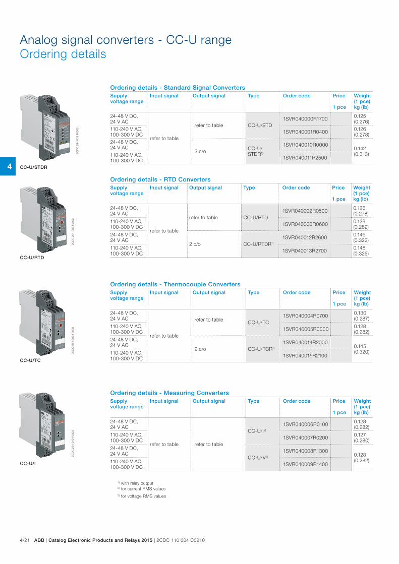
Analog signal converters - CC-U rangeOrdering details
1) with relay output2) for current RMS values3) for voltage RMS values
Ordering details - RTD ConvertersSupply voltage range
Input signal Output signal Type Order code Price
1 pce
Weight(1 pce)kg (lb)
24-48 V DC, 24 V AC
refer to table
refer to table CC-U/RTD1SVR040002R0500 0.126
(0.278)
110-240 V AC, 100-300 V DC 1SVR040003R0600 0.128
(0.282)
24-48 V DC, 24 V AC
2 c/o CC-U/RTDR1)
1SVR040012R2600 0.146 (0.322)
110-240 V AC, 100-300 V DC 1SVR040013R2700 0.148
(0.326)
Ordering details - Standard Signal ConvertersSupply voltage range
Input signal Output signal Type Order code Price
1 pce
Weight(1 pce)kg (lb)
24-48 V DC, 24 V AC
refer to table
refer to table CC-U/STD1SVR040000R1700 0.125
(0.276)110-240 V AC, 100-300 V DC 1SVR040001R0400 0.126
(0.278)24-48 V DC, 24 V AC
2 c/o CC-U/STDR1)
1SVR040010R00000.142 (0.313)110-240 V AC,
100-300 V DC 1SVR040011R2500
2CD
C 2
81 0
03 F
0003
2CD
C 2
81 0
05 F
0003
2CD
C 2
81 0
08 F
0003
2CD
C 2
81 0
12 F
0003
CC-U/STDR
CC-U/RTD
CC-U/TC
CC-U/I
Ordering details - Thermocouple ConvertersSupply voltage range
Input signal Output signal Type Order code Price
1 pce
Weight(1 pce)kg (lb)
24-48 V DC, 24 V AC
refer to table
refer to table CC-U/TC1SVR040004R0700 0.130
(0.287)
110-240 V AC, 100-300 V DC 1SVR040005R0000 0.128
(0.282)
24-48 V DC, 24 V AC
2 c/o CC-U/TCR1)
1SVR040014R20000.145 (0.320)110-240 V AC,
100-300 V DC 1SVR040015R2100
Ordering details - Measuring ConvertersSupply voltage range
Input signal Output signal Type Order code Price
1 pce
Weight(1 pce)kg (lb)
24-48 V DC, 24 V AC
refer to table refer to table
CC-U/I2)
1SVR040006R0100 0.128 (0.282)
110-240 V AC, 100-300 V DC 1SVR040007R0200 0.127
(0.280)
24-48 V DC, 24 V AC
CC-U/V3)
1SVR040008R13000.128 (0.282)110-240 V AC,
100-300 V DC 1SVR040009R1400
4
2CDC 110 004 C0210 | Catalog Electronic Products and Relays 2015 | ABB 4/22
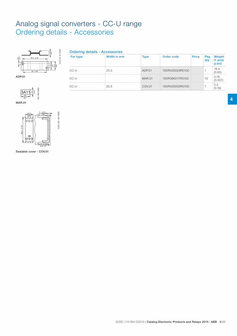
Ordering details - AccessoriesFor type Width in mm Type Order code Price Pkg
qtyWeight(1 pce)g (oz)
CC-U 22.5 ADP.01 1SVR430029R0100 1 18.4(0.65)
CC-U MAR.01 1SVR366017R0100 10 0.19(0.007)
CC-U 22.5 COV.01 1SVR430005R0100 1 5.2 (0.18)
Analog signal converters - CC-U rangeOrdering details - Accessories
2CD
C 2
52 1
87 F
0005
4,5 62,5
60
1011
,5
22,5
.177
”
2.46”
2.36”
.394
”
.886
”
.453
”
2CD
C 2
52 1
85 F
000522,5
68,5
73,5
.886”
2.70
”
.138”.275”
front-to-backsize 107
ADP.01
203A11 8
.315
”
.787”
2CD
C 2
52 1
86 F
0005
MAR.01
Sealable cover - COV.01
4
4/23 ABB | Catalog Electronic Products and Relays 2015 | 2CDC 110 004 C0210
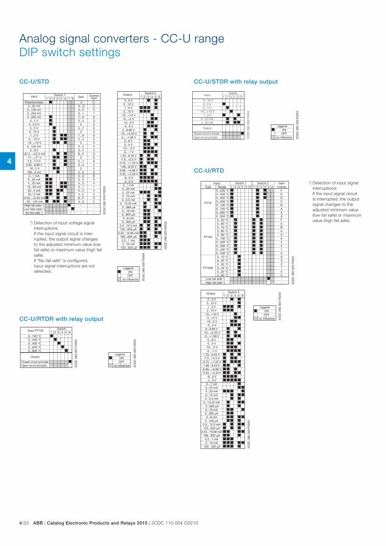
Analog signal converters - CC-U rangeDIP switch settings
*) Detection of input voltage signal interruptions:
If the input signal circuit is inter-rupted, the output signal changes to the adjusted minimum value (low fail safe) or maximum value (high fail safe). If "No fail safe" is configured, input signal interruptions are not detected.
4321 5 876
0...8 V
0...20 mA4...20 mA10...50 mA20...4 mA20...0 mA
0...50 mV0...100 mV0...250 mV0...500 mV
0...1 V
0...5 V
-10...+10 V0...125 mV
1...5 V0...10 V
2... 10 V
-11...+11 V
10...0 V100...0 mV0...1 mA
-55...+55 mA
3...4
2...44...50...14...54...2
A...D4...50...17...93...4
5...7
03...4
7...92
2...4
0
24...5A...D
4...6
3
34143
C5183
6
03
82
3
0
25B
5
64
0
0
D
D
0
0
B...F
5...73...4
---
---
B...F
2CD
C 2
82 0
19 F
0203
Switch 1Input
2.5...7.5 V3.33...9.99 V
High fail safe *)
Gain CoarseType
Potentiometer
0...2.5 V
-22.5...+22.5 mV
-0.45...+0.45 mA
Low faile safe *)No fail safe *)
1 2 43 5 6
-10...-2 V-5...-1 V
-8...0 V-4...0 V0...1 mA
0...20 mA4...20 mA0...10 mA
0...800 µA0...8 mA
0...400 µA
125...625 µA
166...833 µA
2...10 mA100...500 µA
0...666 µA0...16 mA
0...5 V0...10 V1...5 V
2...10 V-10...+10 V-5...+5 V-10...0 V-5...0 V
0...8 V0...4 V
2CD
C 2
82 0
20 F
0203
Switch 2Output
1.25...6.25 V
0...6.66 V-10...+3.33 V-5...+1.66 V
-7.5...+2.5 V-3.75...+1.25 V1.66...8.33 V
-6.66...+6.66 V-3.33...+3.33 V
0...0.5 mA0...13.33 mA
2.5...12.5 mA
3.33...16.66 mA
0.2...1 mA
2CD
C 2
82 0
03 F
0204
OFF
Legend
no influence
ON
CC-U/STD CC-U/STDR with relay output
2CD
C 2
82 0
03 F
0204
OFF
Legend
no influence
ON
1 2 43 5 60...10 V0...5 V0...1 V
-10...+10 V1...5 V
0...20 mA4...20 mA
2CD
C 2
82 0
05 F
0204
SwitchInput
Output
Closed-circuit principleOpen-circuit principle
*) Detection of input signal interruptions:
If the input signal circuit is interrupted, the output signal changes to the adjusted minimum value (low fail safe) or maximum value (high fail safe).
CC-U/RTD
2CD
C 2
82 0
03 F
0204
OFF
Legend
no influence
ON
1 2 43 5 6 1 2 43 5 6
PT10
PT100
PT1000
0...500 °C0...550 °C0...600 °C0...650 °C0...700 °C0...750 °C0...800 °C0...850 °C0...50 °C0...60 °C0...70 °C0...80 °C0...90 °C
0...100 °C0...200 °C
0...400 °C0...300 °C
0...500 °C0...10 °C0...20 °C0...30 °C0...40 °C0...50 °C0...60 °C
FEDCBA98FEBA983
12
0832100
--
2CD
C 2
82 0
23 F
0203
Type RangeSwitch 1 Switch 2Input
Low fail safe *)High fail safe *)
GainCoarse
1 2 43 5 6
-10...-2 V-5...-1 V
-8...0 V-4...0 V0...1 mA
0...20 mA4...20 mA0...10 mA
0...800 µA0...8 mA
0...400 µA
125...625 µA
166...833 µA
2...10 mA100...500 µA
0...666 µA0...16 mA
0...5 V0...10 V1...5 V
2...10 V-10...+10 V
-5...+5 V-10...0 V-5...0 V
0...8 V0...4 V
2CD
C 2
82 0
24 F
0203
Switch 3Output
1.25...6.25 V
0...6.66 V-10...+3.33 V-5...+1.66 V
-7.5...+2.5 V-3.75...+1.25 V1.66...8.33 V
-6.66...+6.66 V-3.33...+3.33 V
0...0.5 mA0...13.33 mA
2.5...12.5 mA
3.33...16.66 mA
0.2...1 mA
CC-U/RTDR with relay output
2CD
C 2
82 0
03 F
0204
OFF
Legend
no influence
ON
1 2 43 5 60...100 °C0...200 °C0...400 °C0...600 °C0...800 °C
2CD
C 2
82 0
07 F
0204
SwitchInput PT100
Output
Closed-circuit principleOpen-circuit principle
4
2CDC 110 004 C0210 | Catalog Electronic Products and Relays 2015 | ABB 4/24
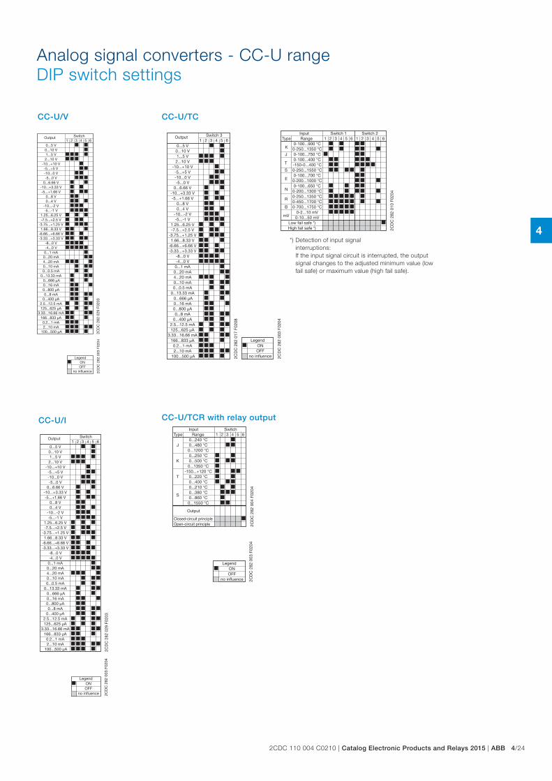
Analog signal converters - CC-U rangeDIP switch settings
CC-U/I
2CD
C 2
82 0
03 F
0204
OFF
Legend
no influence
ON
1 2 43 5 6
-10...-2 V-5...-1 V
-8...0 V-4...0 V0...1 mA0...20 mA4...20 mA0...10 mA
0...800 µA0...8 mA
0...400 µA
125...625 µA
166...833 µA
2...10 mA100...500 µA
0...666 µA0...16 mA
0...5 V0...10 V1...5 V2...10 V
-10...+10 V-5...+5 V-10...0 V-5...0 V
0...8 V0...4 V
2CD
C 2
82 0
29 F
0203
SwitchOutput
1.25...6.25 V
0...6.66 V-10...+3.33 V-5...+1.66 V
-7.5...+2.5 V-3.75...+1.25 V1.66...8.33 V
-6.66...+6.66 V-3.33...+3.33 V
0...0.5 mA0...13.33 mA
2.5...12.5 mA
3.33...16.66 mA
0.2...1 mA
CC-U/V
2CD
C 2
82 0
03 F
0204
OFF
Legend
no influence
ON
1 2 43 5 6
-10...-2 V-5...-1 V
-8...0 V-4...0 V0...1 mA
0...20 mA4...20 mA0...10 mA
0...800 µA0...8 mA
0...400 µA
125...625 µA
166...833 µA
2...10 mA100...500 µA
0...666 µA0...16 mA
0...5 V0...10 V1...5 V
2...10 V-10...+10 V-5...+5 V-10...0 V-5...0 V
0...8 V0...4 V
2CD
C 2
82 0
29 F
0203
SwitchOutput
1.25...6.25 V
0...6.66 V-10...+3.33 V-5...+1.66 V
-7.5...+2.5 V-3.75...+1.25 V1.66...8.33 V
-6.66...+6.66 V-3.33...+3.33 V
0...0.5 mA0...13.33 mA
2.5...12.5 mA
3.33...16.66 mA
0.2...1 mA
*) Detection of input signal interruptions:
If the input signal circuit is interrupted, the output signal changes to the adjusted minimum value (low fail safe) or maximum value (high fail safe).
CC-U/TC
1 2 43 5 6
-10...-2 V-5...-1 V
-8...0 V-4...0 V0...1 mA
0...20 mA4...20 mA0...10 mA
0...800 µA0...8 mA
0...400 µA
125...625 µA
166...833 µA
2...10 mA100...500 µA
0...666 µA0...16 mA
0...5 V0...10 V1...5 V
2...10 V-10...+10 V-5...+5 V-10...0 V-5...0 V
0...8 V0...4 V
2CD
C 2
82 0
17 F
0208
Switch 3Output
1.25...6.25 V
0...6.66 V-10...+3.33 V-5...+1.66 V
-7.5...+2.5 V-3.75...+1.25 V1.66...8.33 V
-6.66...+6.66 V-3.33...+3.33 V
0...0.5 mA0...13.33 mA
2.5...12.5 mA
3.33...16.66 mA
0.2...1 mA
2CD
C 2
82 0
03 F
0204
OFF
Legend
no influence
ON
1 2 43 5 6 1 2 43 5 6
R
B
mV
N
K
J
T
S
E
0-100...900 °C0-250...1350 °C0-100...750 °C0-100...400 °C-150-0...400 °C0-250...1550 °C0-100...700 °C
0-200...1000 °C0-100...650 °C
0-200...1300 °C0-250...1350 °C0-450...1700 °C0-700...1750 °C
0-2...10 mV0-10...50 mV
2CD
C 2
82 0
10 F
0204
Type RangeSwitch 1 Switch 2Input
Low fail safe *)High fail safe *)
CC-U/TCR with relay output
2CD
C 2
82 0
03 F
0204
OFF
Legend
no influence
ON
1 2 43 5 6
S
J
K
T
0...240 °C0...480 °C
0...1200 °C0...250 °C0...500 °C
0...1350 °C-150...+120 °C
0...220 °C0...400 °C0...210 °C0...380 °C0...860 °C
0...1550 °C
2CD
C 2
82 0
04 F
0204
Type RangeSwitchInput
Output
Closed-circuit principleOpen-circuit principle
4
4/25 ABB | Catalog Electronic Products and Relays 2015 | 2CDC 110 004 C0210
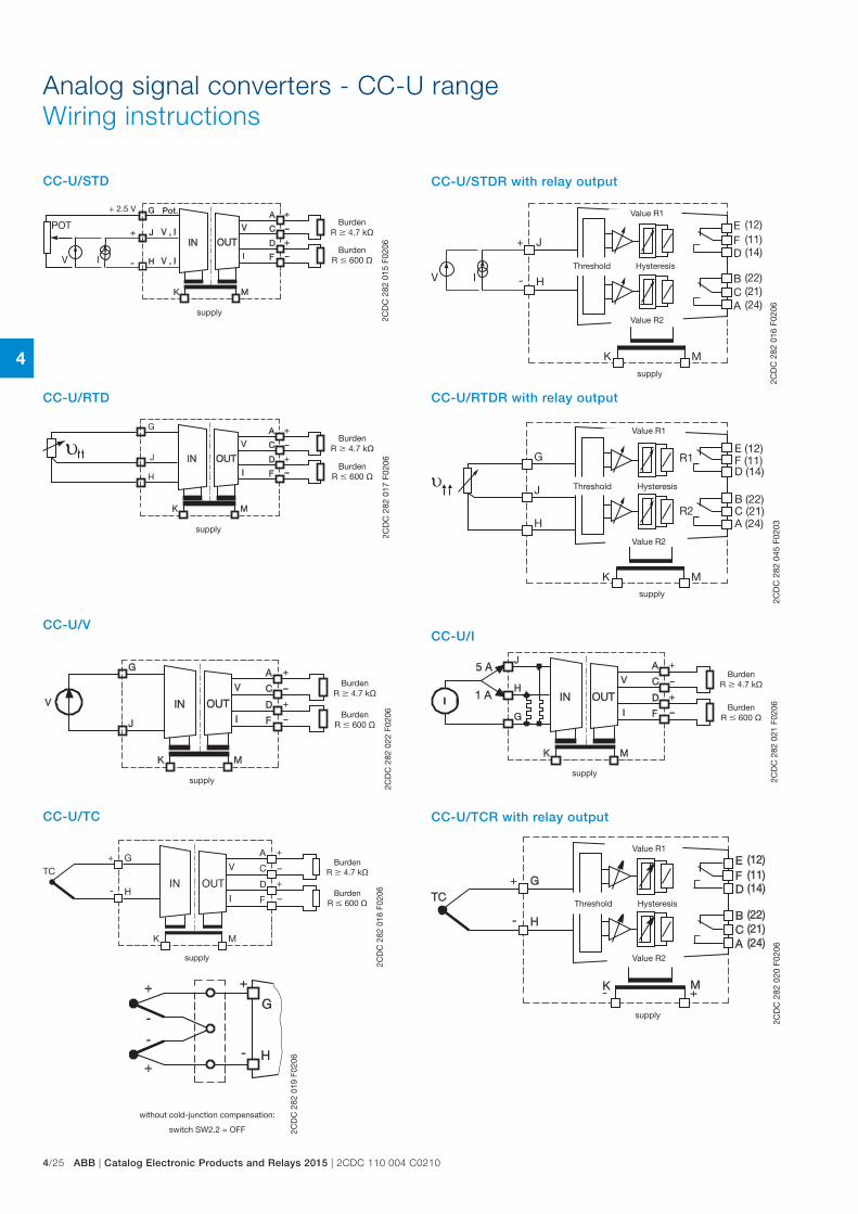
Pot.G
H
J
2CD
C 2
82 0
15 F
0206
BurdenR 4.7 k
BurdenR 600
supply
+ 2.5 V
CC-U/STD
Analog signal converters - CC-U rangeWiring instructions
2CD
C 2
82 0
16 F
0206
Value R1
Value R2
Threshold Hysteresis
supply
CC-U/STDR with relay output
J
H
G
2CD
C 2
82 0
17 F
0206
BurdenR 4.7 k
BurdenR 600
supply
CC-U/RTD
υG
J
H
K M
B (22)C (21)A (24)
E (12)F (11)D (14)
R1
R2
2CD
C 2
82 0
45 F
0203
Value R1
Value R2
Threshold Hysteresis
supply
CC-U/RTDR with relay output2C
DC
282
022
F02
06
BurdenR 4.7 k
BurdenR 600
supply
CC-U/V
2CD
C 2
82 0
21 F
0206
BurdenR 4.7 k
BurdenR 600
supply
CC-U/I
2CD
C 2
82 0
19 F
0206
without cold-junction compensation:
switch SW2.2 = OFF
2CD
C 2
82 0
18 F
0206
BurdenR 4.7 k
BurdenR 600
supply
CC-U/TC
2CD
C 2
82 0
20 F
0206
Value R1
Value R2
Threshold Hysteresis
supply
CC-U/TCR with relay output
4
2CDC 110 004 C0210 | Catalog Electronic Products and Relays 2015 | ABB 4/26
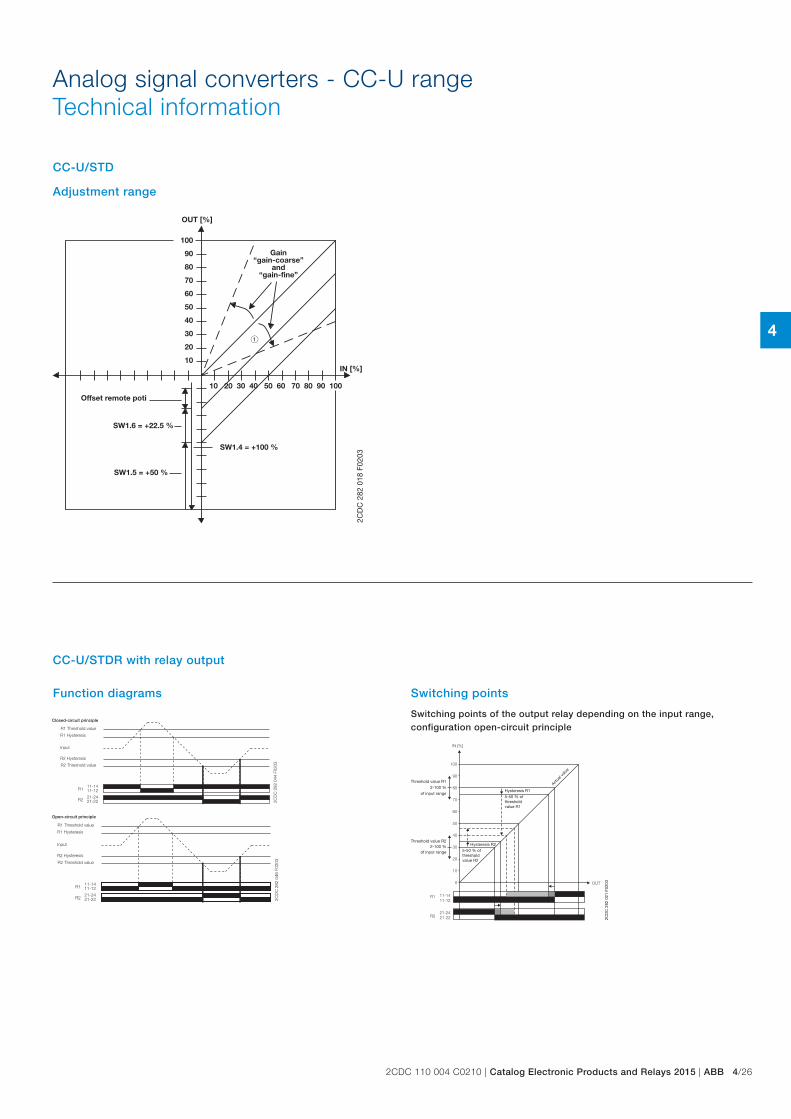
Adjustment range
OUT [%]
IN [%]
SW1.4 = +100 %
SW1.5 = +50 %
100
90
80
70
60
50
40
30
20
10
10 20 30 40 50 60 70 80 90 100
2CD
C 2
82 0
18 F
0203
Offset remote poti
SW1.6 = +22.5 %
Gain“gain-coarse”
and“gain-fine”
CC-U/STD
Analog signal converters - CC-U rangeTechnical information
Function diagrams
Switching points of the output relay depending on the input range, configuration open-circuit principle
OUT
11-1411-12
21-2421-22
R1
R2
IN [%]
100
90
80
70
60
50
40
30
20
10
0
2CD
C 2
82 0
21 F
0203
Hysteresis R15-50 % of threshold value R1
Threshold value R12-100 %
of input range
Threshold value R22-100 %
of input range
Hysteresis R25-50 % of threshold value R2
Actua
l valu
e
Switching points
21-2421-22
11-1411-12
R2
R1
2CD
C 2
82 0
44 F
0203
R1 Threshold value
R1 Hysteresis
R2 Hysteresis
R2 Threshold value
Input
Closed-circuit principle
21-2421-22
11-1411-12
R2
R1
2CD
C 2
82 0
46 F
0203
R1 Threshold value
R1 Hysteresis
R2 Hysteresis
R2 Threshold value
Input
Open-circuit principle
CC-U/STDR with relay output
4
4/27 ABB | Catalog Electronic Products and Relays 2015 | 2CDC 110 004 C0210
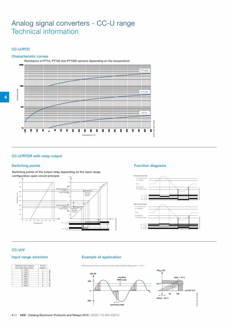
Resistance of PT10, PT100 and PT1000 sensors depending on the temperature
PT1000
PT100
PT10
2CD
C 2
82 0
22 F
0203
Res
ista
nce
[]
Temperature [°C]
Characteristic curves
Analog signal converters - CC-U rangeTechnical information
CC-U/RTD
Switching points of the output relay depending on the input range, configuration open-circuit principle
OUT
11-1411-12
21-2421-22
R1
R2
100
90
80
70
60
50
40
30
20
10
0
IN [%]
800
700
600
500
400
300
200
100
50 100 150 200 250 300 350 400
2CD
C 2
82 0
25 F
0203
Resistance []
Tem
per
atur
e υ
[°C
]
Hysteresis R15-50 % of threshold value R1
Threshold value R12-100 %
of input range
Threshold value R22-100 %
of input range Hysteresis R25-50 % of threshold value R2
Actua
l valu
e
Switching points Function diagrams
21-2421-22
11-1411-12
R2
R1
2CD
C 2
82 0
44 F
0203
R1 Threshold value
R1 Hysteresis
R2 Hysteresis
R2 Threshold value
Input
Closed-circuit principle
21-2421-22
11-1411-12
R2
R1
2CD
C 2
82 0
46 F
0203
R1 Threshold value
R1 Hysteresis
R2 Hysteresis
R2 Threshold value
Input
Open-circuit principle
CC-U/RTDR with relay output
0...100 V0...150 V0...250 V0...300 V0...400 V
0...600 V
0...450 V0...550 V
12345
8
67
2CD
C 2
82 0
12 F
0204
Switchposition
Selecting input range by front-face rotary switch
U(t) [V]
INUeff [V]
OUT [%]
0 50 100
300
0
-300
2CD
C 2
82 0
30 F
0203
Offset 20 %
Gain 15 %resultingRMS value
operating angle
Example of application
CC-U/V
Input range selection
RMS measurement and conversion of a phase-angle controlled voltage signal L1 = 230 V
4
2CDC 110 004 C0210 | Catalog Electronic Products and Relays 2015 | ABB 4/28
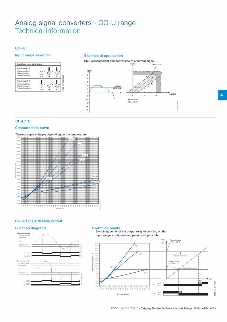
Analog signal converters - CC-U rangeTechnical information
J H G
J H G
5 A 1 A C
5 A 1 A C
2CD
C 2
82 0
33 F
0203
Select input range by terminals
Input range 1 A
Connected linesUsed terminalsTerminal marking
Input range 5 A
Connected linesUsed terminalsTerminal marking
Input range selection
RMS measurement and conversion of a current signal
I(t) [A]
IN [%]
OUT [%]0 50 100
t
5
4
3
2
1
0
-1
-2
-3
-4
-5
2CD
C 2
82 0
28 F
0203Offset 20 %
Gain 15 %
resultingRMS value
Example of application
CC-U/I
Thermocouple voltages depending on the temperature
Typ T
Typ N
Typ K
Typ J
Typ E
Typ R
Typ S
Typ B
-250
-200
-150
-100
-50 0 50 100
150
200
250
300
350
400
450
500
550
600
650
700
750
800
850
900
950
1000
1050
1100
1150
1200
1250
1300
1350
1400
1450
1500
1550
1600
1650
1700
1750
1800
80000
75000
70000
65000
60000
55000
50000
45000
40000
35000
30000
25000
20000
15000
10000
5000
0
-5000
-10000
-15000
2CD
C 2
82 0
26 F
0103
Temperatur [°C]
Ther
moe
lem
ent-
Sp
annu
ng [µ
V]
Characteristic curve
CC-U/TC
CC-U/TCR with relay output
Function diagrams
21-2421-22
11-1411-12
R2
R1
2CD
C 2
82 0
44 F
0203
R1 Threshold value
R1 Hysteresis
R2 Hysteresis
R2 Threshold value
Input
Closed-circuit principle
21-2421-22
11-1411-12
R2
R1
2CD
C 2
82 0
46 F
0203
R1 Threshold value
R1 Hysteresis
R2 Hysteresis
R2 Threshold value
Input
Open-circuit principle
Switching points of the output relay depending on the input range, configuration open-circuit principle
Typ T
Typ J
Typ K
Typ S
IN [%]
100
0 OUT
11-1411-12
21-2421-22
R1
R2
7000
6500
6000
5500
5000
4500
4000
3500
3000
2500
2000
1500
1000
500
0
-500
-1000
-1500
-275
-175 -75 25 125
225
325
425
525
625
725
825
925
1025
1125
1225
1325
1425
1525
1625
1725
1825
2CD
C 2
82 0
27 F
0203
Temperature [°C]
Ther
moc
oup
le v
olta
ge [µ
V]
Threshold value R2 = 400 °C
Release hysteresis
Threshold value R1 = 1000 °C
Release hysteresis
Switching points
4
4/29 ABB | Catalog Electronic Products and Relays 2015 | 2CDC 110 004 C0210
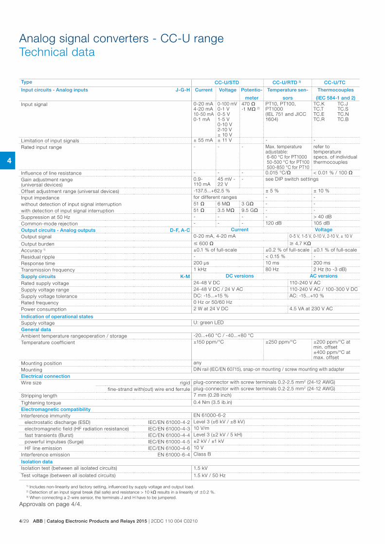
Analog signal converters - CC-U rangeTechnical data
Type CC-U/STD CC-U/RTD 3) CC-U/TC
Input circuits - Analog inputs J-G-H Current Voltage Potentio-
meter
Temperature sen-
sors
Thermocouples
(IEC 584-1 and 2)Input signal 0-20 mA
4-20 mA10-50 mA0-1 mA
0-100 mV0-1 V0-5 V1-5 V0-10 V2-10 V± 10 V
470 -1 M 2)
PT10, PT100, PT1000(IEL 751 and JICC 1604)
TC.KTC.TTC.ETC.R
TC.JTC.STC.NTC.B
Limitation of input signals ± 55 mA ± 11 V - -Rated input range - - - Max. temperature
adjustable: 6-60 °C for PT1000 50-500 °C for PT100 500-850 °C for PT10
refer to temperature specs. of individual thermocouples
Influence of line resistance - - - 0.015 °C/ < 0.01 % / 100 Gain adjustment range (universal devices)
0.9-110 mA
45 mV -22 V
- see DIP switch settings
Offset adjustment range (universal devices) -137.5...+62.5 % ± 5 % ± 10 % Input impedance for different ranges - -without detection of input signal interruption 51 6 M 3 G - -with detection of input signal interruption 51 3.5 M 9.5 G - -Suppression at 50 Hz - - - - > 40 dBCommon-mode rejection - - - 120 dB 105 dBOutput circuits - Analog outputs D-F, A-C Current VoltageOutput signal 0-20 mA, 4-20 mA 0-5 V, 1-5 V, 0-10 V, 2-10 V, ± 10 V
Output burden 600 4.7 K
Accuracy 1) ±0.1 % of full-scale ±0.2 % of full-scale ±0.1 % of full-scaleResidual ripple - < 0.15 % -Response time 200 µs 10 ms 200 msTransmission frequency 1 kHz 80 Hz 2 Hz (to -3 dB)
Supply circuits K-M DC versions AC versions
Rated supply voltage 24-48 V DC 110-240 V ACSupply voltage range 24-48 V DC / 24 V AC 110-240 V AC / 100-300 V DCSupply voltage tolerance DC: -15...+15 % AC: -15...+10 %Rated frequency 0 Hz or 50/60 HzPower consumption 2 W at 24 V DC 4.5 VA at 230 V AC
Indication of operational statesSupply voltage U: green LEDGeneral dataAmbient temperature range operation / storage -20...+60 °C / -40...+80 °CTemperature coefficient ±150 ppm/°C ±250 ppm/°C ±200 ppm/°C at
min. offset±400 ppm/°C at max. offset
Mounting position anyMounting DIN rail (IEC/EN 60715), snap-on mounting / screw mounting with adapterElectrical connectionWire size rigid plug-connector with screw terminals 0.2-2.5 mm2 (24-12 AWG)
fine-strand with(out) wire end ferrule plug-connector with screw terminals 0.2-2.5 mm2 (24-12 AWG)Stripping length 7 mm (0.28 inch)
Tightening torque 0.4 Nm (3.5 ib.in)Electromagnetic compatibilityInterference immunity EN 61000-6-2
electrostatic discharge (ESD) IEC/EN 61000-4-2 Level 3 (±6 kV / ±8 kV)electromagnetic field (HF radiation resistance) IEC/EN 61000-4-3 10 V/mfast transients (Burst) IEC/EN 61000-4-4 Level 3 (±2 kV / 5 kH)powerful impulses (Surge) IEC/EN 61000-4-5 ±2 kV / ±1 kVHF line emission IEC/EN 61000-4-6 10 V
Interference emission EN 61000-6-4 Class B
Isolation dataIsolation test (between all isolated circuits) 1.5 kV
Test voltage (between all isolated circuits) 1.5 kV / 50 Hz
1) Includes non-linearity and factory setting, influenced by supply voltage and output load.2) Detection of an input signal break (fail safe) and resistance > 10 k results in a linearity of 0.2 %.3) When connecting a 2-wire sensor, the terminals J and H have to be jumpered.
Approvals on page 4/4.
4
2CDC 110 004 C0210 | Catalog Electronic Products and Relays 2015 | ABB 4/30
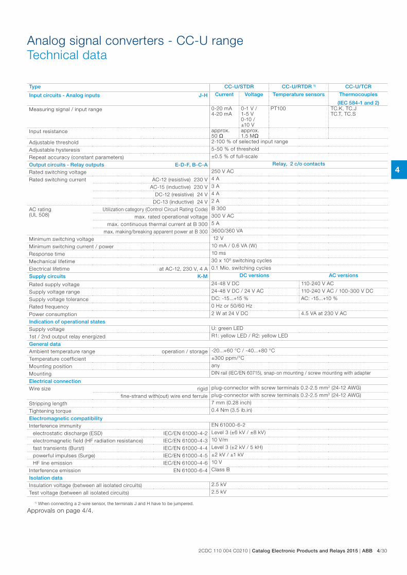
Analog signal converters - CC-U rangeTechnical data
Type CC-U/STDR CC-U/RTDR 1) CC-U/TCR
Input circuits - Analog inputs J-H Current Voltage Temperature sensors Thermocouples
(IEC 584-1 and 2)Measuring signal / input range 0-20 mA
4-20 mA0-1 V / 1-5 V0-10 / ±10 V
PT100 TC.K, TC.JTC.T, TC.S
Input resistance approx. 50
approx. 1.5 M
Adjustable threshold 2-100 % of selected input range
Adjustable hysteresis 5-50 % of threshold
Repeat accuracy (constant parameters) ±0.5 % of full-scale
Output circuits - Relay outputs E-D-F, B-C-A Relay, 2 c/o contacts
Rated switching voltage 250 V AC
Rated switching current AC-12 (resistive) 230 V 4 A
AC-15 (inductive) 230 V 3 A
DC-12 (resistive) 24 V 4 A
DC-13 (inductive) 24 V 2 A
AC rating (UL 508)
Utilization category (Control Circuit Rating Code) B 300
max. rated operational voltage 300 V AC
max. continuous thermal current at B 300 5 A
max. making/breaking apparent power at B 300 3600/360 VA
Minimum switching voltage 12 V
Minimum switching current / power 10 mA / 0.6 VA (W)
Response time 10 ms
Mechanical lifetime 30 x 106 switching cycles
Electrical lifetime at AC-12, 230 V, 4 A 0.1 Mio. switching cycles
Supply circuits K-M DC versions AC versions
Rated supply voltage 24-48 V DC 110-240 V AC
Supply voltage range 24-48 V DC / 24 V AC 110-240 V AC / 100-300 V DC
Supply voltage tolerance DC: -15...+15 % AC: -15...+10 %
Rated frequency 0 Hz or 50/60 Hz
Power consumption 2 W at 24 V DC 4.5 VA at 230 V AC
Indication of operational statesSupply voltage U: green LED
1st / 2nd output relay energized R1: yellow LED / R2: yellow LED
General dataAmbient temperature range operation / storage -20...+60 °C / -40...+80 °C
Temperature coefficient ±300 ppm/°C
Mounting position any
Mounting DIN rail (IEC/EN 60715), snap-on mounting / screw mounting with adapter
Electrical connectionWire size rigid plug-connector with screw terminals 0.2-2.5 mm2 (24-12 AWG)
fine-strand with(out) wire end ferrule plug-connector with screw terminals 0.2-2.5 mm2 (24-12 AWG)
Stripping length 7 mm (0.28 inch)
Tightening torque 0.4 Nm (3.5 ib.in)
Electromagnetic compatibilityInterference immunity EN 61000-6-2
electrostatic discharge (ESD) IEC/EN 61000-4-2 Level 3 (±6 kV / ±8 kV)
electromagnetic field (HF radiation resistance) IEC/EN 61000-4-3 10 V/m
fast transients (Burst) IEC/EN 61000-4-4 Level 3 (±2 kV / 5 kH)
powerful impulses (Surge) IEC/EN 61000-4-5 ±2 kV / ±1 kV
HF line emission IEC/EN 61000-4-6 10 V
Interference emission EN 61000-6-4 Class B
Isolation dataInsulation voltage (between all isolated circuits) 2.5 kV
Test voltage (between all isolated circuits) 2.5 kV
1) When connecting a 2-wire sensor, the terminals J and H have to be jumpered.
Approvals on page 4/4.
4
4/31 ABB | Catalog Electronic Products and Relays 2015 | 2CDC 110 004 C0210
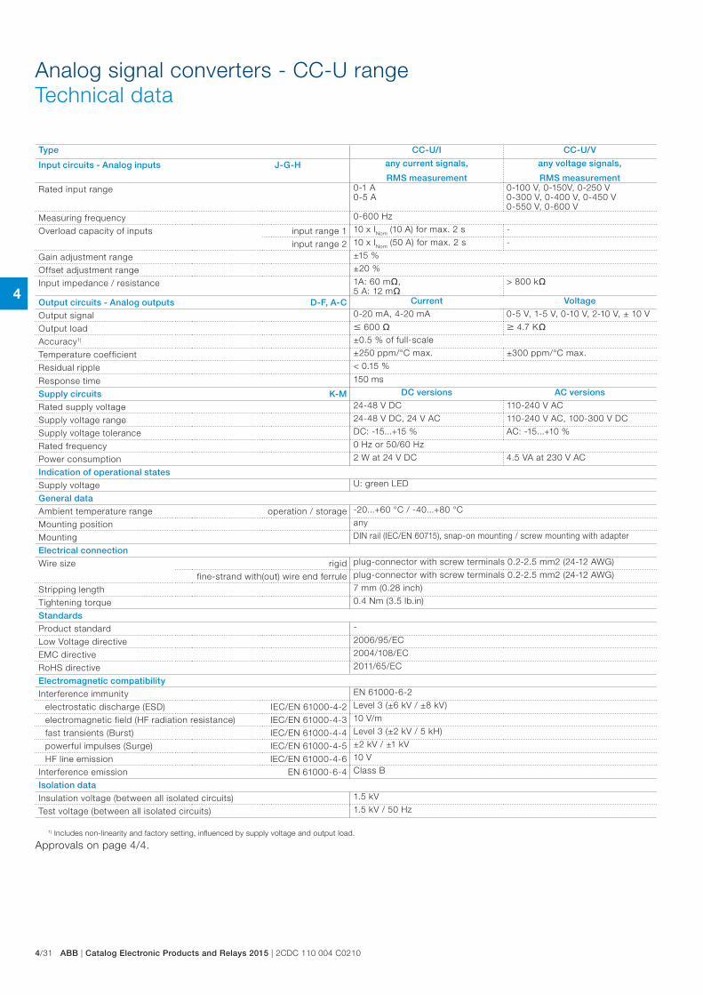
Analog signal converters - CC-U rangeTechnical data
Type CC-U/I CC-U/V
Input circuits - Analog inputs J-G-H any current signals,
RMS measurement
any voltage signals,
RMS measurementRated input range 0-1 A
0-5 A0-100 V, 0-150V, 0-250 V0-300 V, 0-400 V, 0-450 V0-550 V, 0-600 V
Measuring frequency 0-600 Hz
Overload capacity of inputs input range 1 10 x INom (10 A) for max. 2 s -
input range 2 10 x INom (50 A) for max. 2 s -
Gain adjustment range ±15 %
Offset adjustment range ±20 %
Input impedance / resistance 1A: 60 m, 5 A: 12 m
> 800 k
Output circuits - Analog outputs D-F, A-C Current Voltage
Output signal 0-20 mA, 4-20 mA 0-5 V, 1-5 V, 0-10 V, 2-10 V, ± 10 V
Output load 600 4.7 K
Accuracy1) ±0.5 % of full-scale
Temperature coefficient ±250 ppm/°C max. ±300 ppm/°C max.
Residual ripple < 0.15 %
Response time 150 ms
Supply circuits K-M DC versions AC versions
Rated supply voltage 24-48 V DC 110-240 V AC
Supply voltage range 24-48 V DC, 24 V AC 110-240 V AC, 100-300 V DC
Supply voltage tolerance DC: -15...+15 % AC: -15...+10 %
Rated frequency 0 Hz or 50/60 Hz
Power consumption 2 W at 24 V DC 4.5 VA at 230 V AC
Indication of operational states
Supply voltage U: green LED
General data
Ambient temperature range operation / storage -20...+60 °C / -40...+80 °C
Mounting position any
Mounting DIN rail (IEC/EN 60715), snap-on mounting / screw mounting with adapter
Electrical connection
Wire size rigid plug-connector with screw terminals 0.2-2.5 mm2 (24-12 AWG)
fine-strand with(out) wire end ferrule plug-connector with screw terminals 0.2-2.5 mm2 (24-12 AWG)
Stripping length 7 mm (0.28 inch)
Tightening torque 0.4 Nm (3.5 lb.in)
Standards
Product standard -
Low Voltage directive 2006/95/EC
EMC directive 2004/108/EC
RoHS directive 2011/65/EC
Electromagnetic compatibility
Interference immunity EN 61000-6-2
electrostatic discharge (ESD) IEC/EN 61000-4-2 Level 3 (±6 kV / ±8 kV)
electromagnetic field (HF radiation resistance) IEC/EN 61000-4-3 10 V/m
fast transients (Burst) IEC/EN 61000-4-4 Level 3 (±2 kV / 5 kH)
powerful impulses (Surge) IEC/EN 61000-4-5 ±2 kV / ±1 kV
HF line emission IEC/EN 61000-4-6 10 V
Interference emission EN 61000-6-4 Class B
Isolation data
Insulation voltage (between all isolated circuits) 1.5 kV
Test voltage (between all isolated circuits) 1.5 kV / 50 Hz
1) Includes non-linearity and factory setting, influenced by supply voltage and output load.
Approvals on page 4/4.
4
2CDC 110 004 C0210 | Catalog Electronic Products and Relays 2015 | ABB 4/32
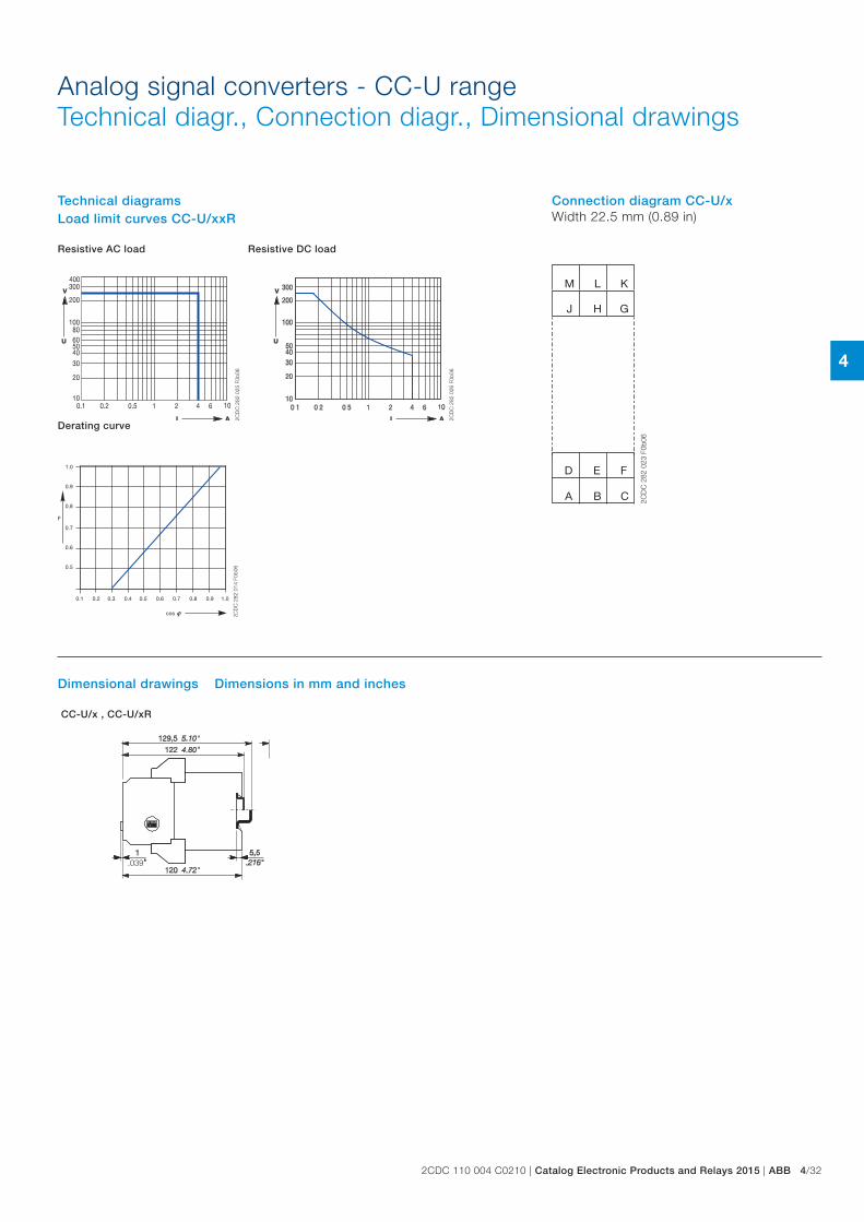
Analog signal converters - CC-U rangeTechnical diagr., Connection diagr., Dimensional drawings
.039
2CD
C 2
82 0
24 F
0b06
J
D F
G
M
H
L K
A C
E
B 2CD
C 2
82 0
23 F
0b06
CC-U/x , CC-U/xR
2CD
C 2
82 0
25 F
0b06
1.0
0.9
0.8
0.7
0.6
0.5
F
0.1 0.2 0.3 0.4 0.5 0.6 0.7 0.8 0.9 1.0
cos 2CD
C 2
82 0
14 F
0b06
2CD
C 2
82 0
26 F
0b06
Dimensional drawings Dimensions in mm and inches
Connection diagram CC-U/xWidth 22.5 mm (0.89 in)
Technical diagramsLoad limit curves CC-U/xxR
Resistive AC load Resistive DC load
Derating curve
4
4/33 ABB | Catalog Electronic Products and Relays 2015 | 2CDC 110 004 C0210
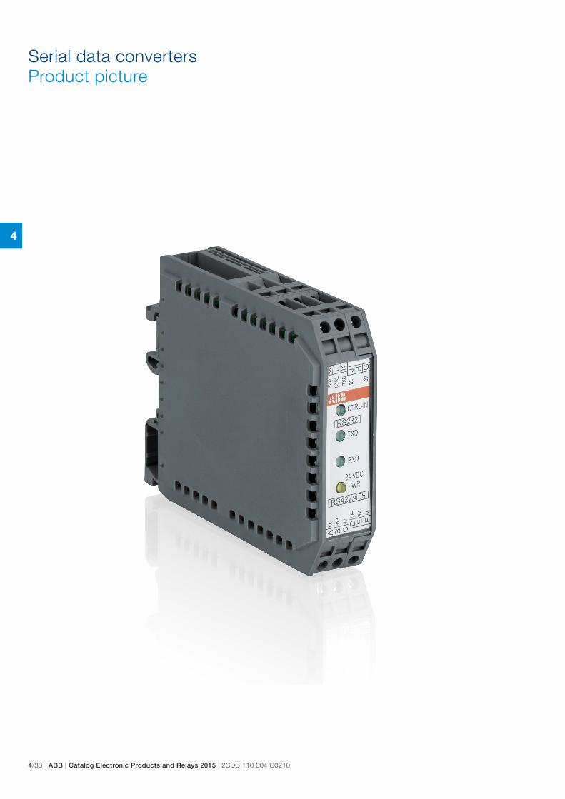
Serial data convertersProduct picture
4
2CDC 110 004 C0210 | Catalog Electronic Products and Relays 2015 | ABB 4/34
Serial data convertersTable of contents
Serial data converters
Benefits and advantages 4/35
Selection table 4/36
Ordering details 4/37
Technical information 4/38
Technical data 4/46
4
4/35 ABB | Catalog Electronic Products and Relays 2015 | 2CDC 110 004 C0210
ILPH RS 232 - 485 / Ethernet – Electrical isolation between power supply and input/output – RS232 on SUBD 9 points or screw connectors – RS485 on removable screw connectors – Ethernet 10/100 Mbit/s, RJ45 connector – Power supply 10-34 VDC and 10-24 VAC – Possible to have a redundant 10-34 VDC power supply – Economic with low consumption – Up to 100m with CAT5 cable without Hub or Switch – Good EMC characteristics – Up to 2 Modbus®\TCP Masters
Available modes: – Modbus®\TCP to Modbus® RTU – Transparent Client or Server mode – SMTP mode (Mail mode)
Standards: TPC/IP, TELNET, DHCP, FTP – Specifics functions in Modbus® protocol: – Concentrator (Asynchronous mode) up to 1200 words – AC31 programming
Modbus® Easy Net mode : this mode could be used to exchange data without a Modbus®/TCP master. The data are logged in a table and could be distributed to one or all the others e-ILPH participants on Ethernet.
ILPH RS 232 / RS 422 - 485RS 232 to RS 422-485 serial link with or without electrical isolation – Baudrate up to 38.4 kbit/s – Transmission distance up to 1200 m – RS 485 1 or 2 pair handling – Usable in "noisy" environments – 24 V DC power supply – CE marked
ILPH RS 232 / RS 422 - 485 – Electrical isolation between power supply and input/output – RS 485 switch on 2 or 4 wires – Baudrate up to 38.4 kbit/s – Transmission distance up to 1200 m – RS 485 1 or 2 pair handling – Usable in "noisy" environments – 24...48 V DC and 115...230 V AC power supply – CE marked
ILPH RS 232 / RS 2323 way electrical isolator between RS 232 serial interface and another RS 232 serial interface. – Ensures triple insulation between the 2 serial interfaces and
between each and power supply – Baudrate up to 19.2 kbit/s (up to 64 kbit/s depending on cable) – Transmission distance up to 15 m – Can be used in "noisy" environments – Power supply from 24...48 V DC and 115...230 V AC CE
marking
ILPH RS 422 - 485 / RS 422 - 485Electrical isolated connection between an RS 422-485 (1 or 2 pairs) and an RS 422 485 (1 or 2 pairs) serial link. It amplifies the signal beyond the 1200 m limit distance of the RS 422-485 and only needs a minimum of 1.5 character delay time to switch off the RS 485 drivers. – Electrical isolation between power supply/output and input/
output – Baudrate up to 500 kbit/s (up to 200 m) – Transmission distance up to 1200m at 38.4 kbit/s – Usable in "noisy" environments – 2/4 wires automatic handling – 24 V DC power supply – CE marked
ILPH RS 232 / FO – Converter for RS 232 to fiber optical serial link glass. – Electrical isolation between power supply and input/output – Baud rate up to 115.2 kbit/s – Transmission distance up to 4 km – Usable in "very noisy" environments – 20...42 V AC/DC power supply – CE marked
ILPH RS 485 / FOConverter for RS 485 (1 pair) to optical fiber serial link glass. – Electrical isolation between power supply and input/output – Baud rate up to 1.5 Mbit/s – Transmission distance up to 4 km – Usable in "very noisy" environments – 20...42 V AC/DC power supply – CE marked
ILPH CL / RS 422 - 485Electrical isolated converter for current loop to RS 422-485 (1 or 2 pairs) serial link. – Electrical isolation between power supply/current loop and
RS 422-485/current loop – Active/passive 0...20 mA / 4...20 mA selectable
Positive or negative logic selectable – Baudrate up to 38.4 kbit/s (up to 2400 m)
Transmission distance up to 2400 m (1200 m RS 485 and 1200 m current loop)
– Usable in "noisy" environments – 24 V DC power supply – CE marked
ILPH RS 232 / CLElectrical isolated Converter for RS 232 to current loop serial link. – Electrical isolation between power supply/current loop and
RS 232/current loop – Active/Passive 0...20 mA / 4...20 mA selectable
Positive or negative logic selectable – Baudrate up to 38.4 kbit/s – Transmission distance up to 1200 m – Usable in "noisy" environments – 24 V DC power supply – CE marked
Serial data convertersBenefits and advantages
4
2CDC 110 004 C0210 | Catalog Electronic Products and Relays 2015 | ABB 4/36
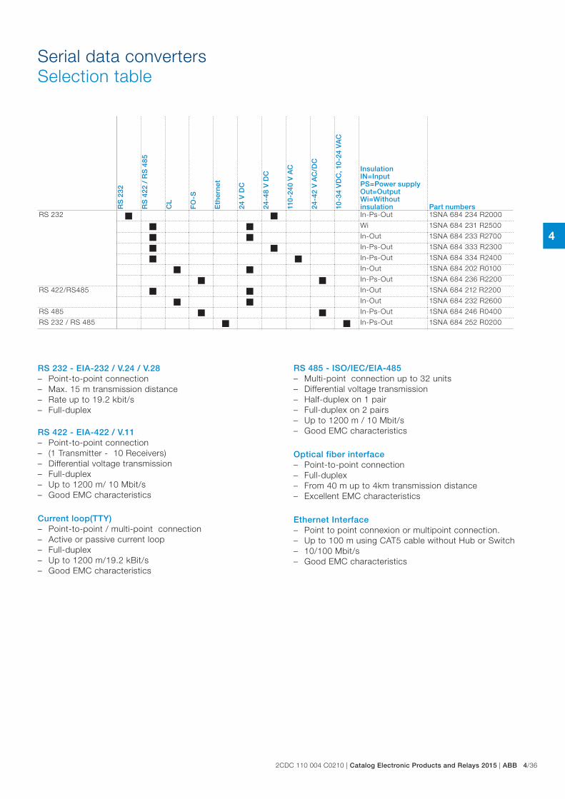
Serial data convertersSelection table
RS 232 - EIA-232 / V.24 / V.28 – Point-to-point connection – Max. 15 m transmission distance – Rate up to 19.2 kbit/s – Full-duplex
RS 422 - EIA-422 / V.11 – Point-to-point connection – (1 Transmitter - 10 Receivers) – Differential voltage transmission – Full-duplex – Up to 1200 m/ 10 Mbit/s – Good EMC characteristics
Current loop(TTY) – Point-to-point / multi-point connection – Active or passive current loop – Full-duplex – Up to 1200 m/19.2 kBit/s – Good EMC characteristics
RS 485 - ISO/IEC/EIA-485 – Multi-point connection up to 32 units – Differential voltage transmission – Half-duplex on 1 pair – Full-duplex on 2 pairs – Up to 1200 m / 10 Mbit/s – Good EMC characteristics
Optical fiber interface – Point-to-point connection – Full-duplex – From 40 m up to 4km transmission distance – Excellent EMC characteristics
Ethernet Interface – Point to point connexion or multipoint connection. – Up to 100 m using CAT5 cable without Hub or Switch – 10/100 Mbit/s – Good EMC characteristics
RS
232
RS
422
/ R
S 4
85
CL
FO
-S
Eth
ern
et
24 V
DC
24-4
8 V
DC
110
-240
V A
C
24-4
2 V
AC
/DC
10-3
4 V
DC
, 10
-24
VA
C
Insulation IN=InputPS=Power supplyOut=OutputWi=Without insulation Part numbers
RS 232 In-Ps-Out 1SNA 684 234 R2000
Wi 1SNA 684 231 R2500
In-Out 1SNA 684 233 R2700
In-Ps-Out 1SNA 684 333 R2300
In-Ps-Out 1SNA 684 334 R2400
In-Out 1SNA 684 202 R0100
In-Ps-Out 1SNA 684 236 R2200
RS 422/RS485 In-Out 1SNA 684 212 R2200
In-Out 1SNA 684 232 R2600
RS 485 In-Ps-Out 1SNA 684 246 R0400
RS 232 / RS 485 In-Ps-Out 1SNA 684 252 R0200
4
4/37 ABB | Catalog Electronic Products and Relays 2015 | 2CDC 110 004 C0210
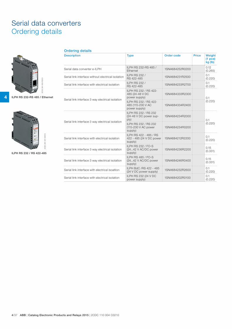
Serial data convertersOrdering details
Ordering detailsDescription Type Order code Price Weight
(1 pce)kg (lb)
Serial data converter e-ILPH ILPH RS 232-RS 485 / Ethernet 1SNA684252R0200 0.12
(0.265)
Serial link interface without electrical isolation ILPH RS 232 / RS 422-485 1SNA684231R2500 0.1
(0.220)
Serial link interface with electrical isolation ILPH RS 232 / RS 422-485 1SNA684233R2700 0.1
(0.220)
Serial link interface 3 way electrical isolation
ILPH RS 232 / RS 422-485 (24-48 V DC power supply)
1SNA684333R23000.1 (0.220)ILPH RS 232 / RS 422-
485 (115-230 V AC power supply)
1SNA684334R2400
Serial link interface 3 way electrical isolation
ILPH RS 232 / RS 232 (24-48 V DC power sup-ply)
1SNA684234R20000.1 (0.220)ILPH RS 232 / RS 232
(115-230 V AC power supply)
1SNA684234R0200
Serial link interface with electrical isolationILPH RS 422 - 485 / RS 422 - 485 (24 V DC power supply)
1SNA684212R2200 0.1 (0.220)
Serial link interface 3 way electrical isolationILPH RS 232 / FO-S (24...42 V AC/DC power supply)
1SNA684236R2200 0.15 (0.331)
Serial link interface 3 way electrical isolationILPH RS 485 / FO-S (24...42 V AC/DC power supply)
1SNA684246R0400 0.15 (0.331)
Serial link interface with electrical isoaltion ILPH BdC /RS 422 - 485 (24 V DC power supply) 1SNA684232R2600 0.1
(0.220)
Serial link interface with electrical isolation ILPH RS 232 (24 V DC power supply) 1SNA684202R0100 0.1
(0.220)
2CD
C 2
81 0
03 F
0013
2CD
C 2
81 0
01 S
0013
ILPH RS 232-RS 485 / Ethernet
ILPH RS 232 / RS 422-485
4
2CDC 110 004 C0210 | Catalog Electronic Products and Relays 2015 | ABB 4/38
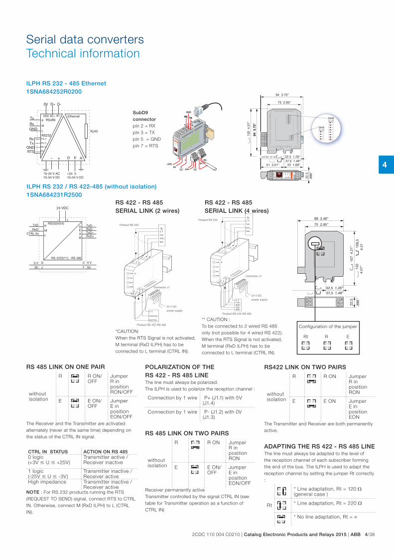
Serial data convertersTechnical information
ILPH RS 232 - 485 Ethernet 1SNA684252R0200
+24V0V
24V
TXTX
GND
RXRX
B1+
B2-
M
JH
G
ML
K
DE
A
GND
RX
TX
Ethernet
LINK
TXD
RXD
e-ILPH
SPEE
D
PWR
ACTIVITY
M LK
JH
G
ML
K
43
21
ON
43
21
ON56
78
KL
DE A
SubD9 connector pin 2 = RX pin 3 = TX pin 5 = GND pin 7 = RTS
center of rail
ILPH RS 232 / RS 422-485 (without isolation) 1SNA684231R2500
*CAUTION: When the RTS Signal is not activated, M terminal (RxD ILPH) has to be connected to L terminal (CTRL IN).
RS 422 - RS 485 SERIAL LINK (2 wires)
Product RS 232
Connector J1
24 V DC
power supply
Product RS 422-RS 485
** CAUTION :To be connected to 2 wired RS 485 only (not possible for 4 wired RS 422). When the RTS Signal is not activated, M terminal (RxD ILPH) has to be connected to L terminal (CTRL IN).
RS 422 - RS 485 SERIAL LINK (4 wires)
Product RS 232
Connector J1
24 V DC
power supply
Product RS 422-RS 485
RS 485 LINK ON ONE PAIR
without isolation
R R ON/OFF
Jumper R in position RON/OFF
E E ON/OFF
Jumper E in positionEON/OFF
The Receiver and the Transmitter are activated alternately (never at the same time) depending on the status of the CTRL IN signal.
CTRL IN STATUS ACTION ON RS 4850 logic (+3V U +25V)
Transmitter active / Receiver inactive
1 logic (-25V U -3V)
Transmitter inactive / Receiver active
High impedance Transmitter inactive / Receiver active
NOTE : For RS 232 products running the RTS (REQUEST TO SEND) signal, connect RTS to CTRL IN. Otherwise, connect M (RxD ILPH) to L (CTRL IN).
RS422 LINK ON TWO PAIRS
without isolation
R R ON Jumper R in position RON
E E ON Jumper E in position EON
The Transmitter and Receiver are both permanently active.
ADAPTING THE RS 422 - RS 485 LINEThe line must always be adapted to the level of the reception channel of each subscriber forming the end of the bus. The ILPH is used to adapt the reception channel by setting the jumper Rt correctly :
Rt
* Line adaptation, Rt = 120 Ω (general case )
* Line adaptation, Rt = 220 Ω
* No line adaptation, Rt = ∝
POLARIZATION OF THE RS 422 - RS 485 LINEThe line must always be polarized. The ILPH is used to polarize the reception channel :
Connection by 1 wire P+ (J1.1) with 5V (J1.4)
Connection by 1 wire P- (J1.2) with 0V (J1.3)
RS 485 LINK ON TWO PAIRS
without isolation
R R ON Jumper R in position RON
E E ON/OFF
Jumper E in position EON/OFF
Receiver permanently active Transmitter controlled by the signal CTRL IN (see table for Transmitter operation as a function of CTRL IN)
Configuration of the jumper
Rt R E
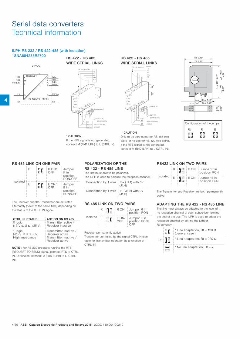
4
4/39 ABB | Catalog Electronic Products and Relays 2015 | 2CDC 110 004 C0210
ILPH RS 232 / RS 422-485 (with isolation) 1SNA684233R2700
Serial data convertersTechnical information
** CAUTION :Only to be connected for RS 485 two pairs (of no use for RS 422 two pairs). If the RTS signal is not generated, connect M (RxD ILPH) to L (CTRL IN).
* CAUTION : If the RTS signal is not generated, connect M (RxD ILPH) to L (CTRL IN).
RS 422 - RS 485 WIRE SERIAL LINKS
RS 422 - RS 485 WIRE SERIAL LINKS
Connector J1
24 V DC
power supply
RS 422-RS 485
product
RS 232 product
Connector J1
24 V DC
power supply
RS 422-RS 485
product
RS 232 product
Configuration of the jumper
Rt R E
RS 485 LINK ON ONE PAIR
Isolated
R R ON/OFF
Jumper R in position RON/OFF
E E ON/OFF
Jumper E in position EON/OFF
The Receiver and the Transmitter are activated alternately (never at the same time) depending on the status of the CTRL IN signal.
CTRL IN STATUS ACTION ON RS 4850 logic (+3 V U +25 V)
Transmitter active / Receiver inactive
1 logic (-25 V U -3V)
Transmitter inactive / Receiver active
High impedance Transmitter inactive / Receiver active
NOTE : For RS 232 products running the RTS (REQUEST TO SEND) signal, connect RTS to CTRL IN. Otherwise, connect M (RxD I LPH) to L (CTRL IN).
RS422 LINK ON TWO PAIRS
Isolated
R R ON Jumper R in position RON
E E ON Jumper E in position EON
The Transmitter and Receiver are both permanently active.
ADAPTING THE RS 422 - RS 485 LINEThe line must always be adapted to the level of t he reception channel of each subscriber forming the end of the bus. The ILPH is used to adapt the reception channel by setting the jumper Rt correctly :
Rt
* Line adaptation, Rt = 120 Ω (general case )
* Line adaptation, Rt = 220 Ω
* No line adaptation, Rt = ∝
POLARIZATION OF THE RS 422 - RS 485 LINEThe line must always be polarized. The ILPH is used to polarize the reception channel :
Connection by 1 wire P+ (J1.1) with 5V (J1.4)
Connection by 1 wire P- (J1.2) with 0V (J1.3)
RS 485 LINK ON TWO PAIRS
Isolated
R R ON Jumper R in position RON
E E ON/OFF
Jumper E in position EON/OFF
Receiver permanently active Transmitter controlled by the signal CTRL IN (see table for Transmitter operation as a function of CTRL IN)
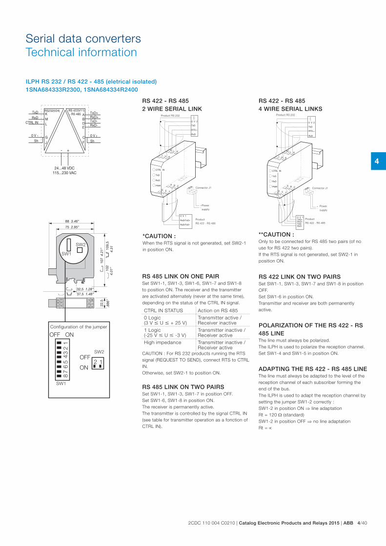
4
2CDC 110 004 C0210 | Catalog Electronic Products and Relays 2015 | ABB 4/40
Serial data convertersTechnical information
Configuration of the jumper
SW1
SW1
SW2
SW2
ILPH RS 232 / RS 422 - 485 (eletrical isolated) 1SNA684333R2300, 1SNA684334R2400
RS 422 - RS 485 2 WIRE SERIAL LINK
**CAUTION :Only to be connected for RS 485 two pairs (of no use for RS 422 two pairs).If the RTS signal is not generated, set SW2-1 in position ON.
*CAUTION : When the RTS signal is not generated, set SW2-1 in position ON.
RS 422 - RS 485 4 WIRE SERIAL LINKS
Product RS 232
Connector J1
Power
supply
Product
RS 422 - RS 485
Product RS 232
Connector J1
Power
supply
Product
RS 422 - RS 485
RS 485 LINK ON ONE PAIRSet SW1-1, SW1-3, SW1-6, SW1-7 and SW1-8 to position ON. The receiver and the transmitter are activated alternately (never at the same time), depending on the status of the CTRL IN signal.
CTRL IN STATUS Action on RS 4850 Logic (3 V U + 25 V)
Transmitter active / Receiver inactive
1 Logic (-25 V U -3 V)
Transmitter inactive / Receiver active
High impedance Transmitter inactive / Receiver active
CAUTION : For RS 232 products running the RTS signal (REQUEST TO SEND), connect RTS to CTRL IN. Otherwise, set SW2-1 to position ON.
RS 485 LINK ON TWO PAIRSSet SW1-1, SW1-3, SW1-7 in position OFF. Set SW1-6, SW1-8 in position ON. The receiver is permanently active. The transmitter is controlled by the signal CTRL IN (see table for transmitter operation as a fonction of CTRL IN).
RS 422 LINK ON TWO PAIRSSet SW1-1, SW1-3, SW1-7 and SW1-8 in position OFF. Set SW1-6 in position ON. Transmitter and receiver are both permanently active.
POLARIZATION OF THE RS 422 - RS 485 LINEThe line must always be polarized. The ILPH is used to polarize the reception channel. Set SW1-4 and SW1-5 in position ON.
ADAPTING THE RS 422 - RS 485 LINEThe line must always be adapted to the level of the reception channel of each subscriber forming the end of the bus.The ILPH is used to adapt the reception channel by setting the jumper SW1-2 correctly :SW1-2 in position ON ⇒ line adaptation Rt = 120 Ω (standard) SW1-2 in position OFF ⇒ no line adaptation Rt = ∝
1
1
2
2
OFF ON
ON
OFF
34
56
78
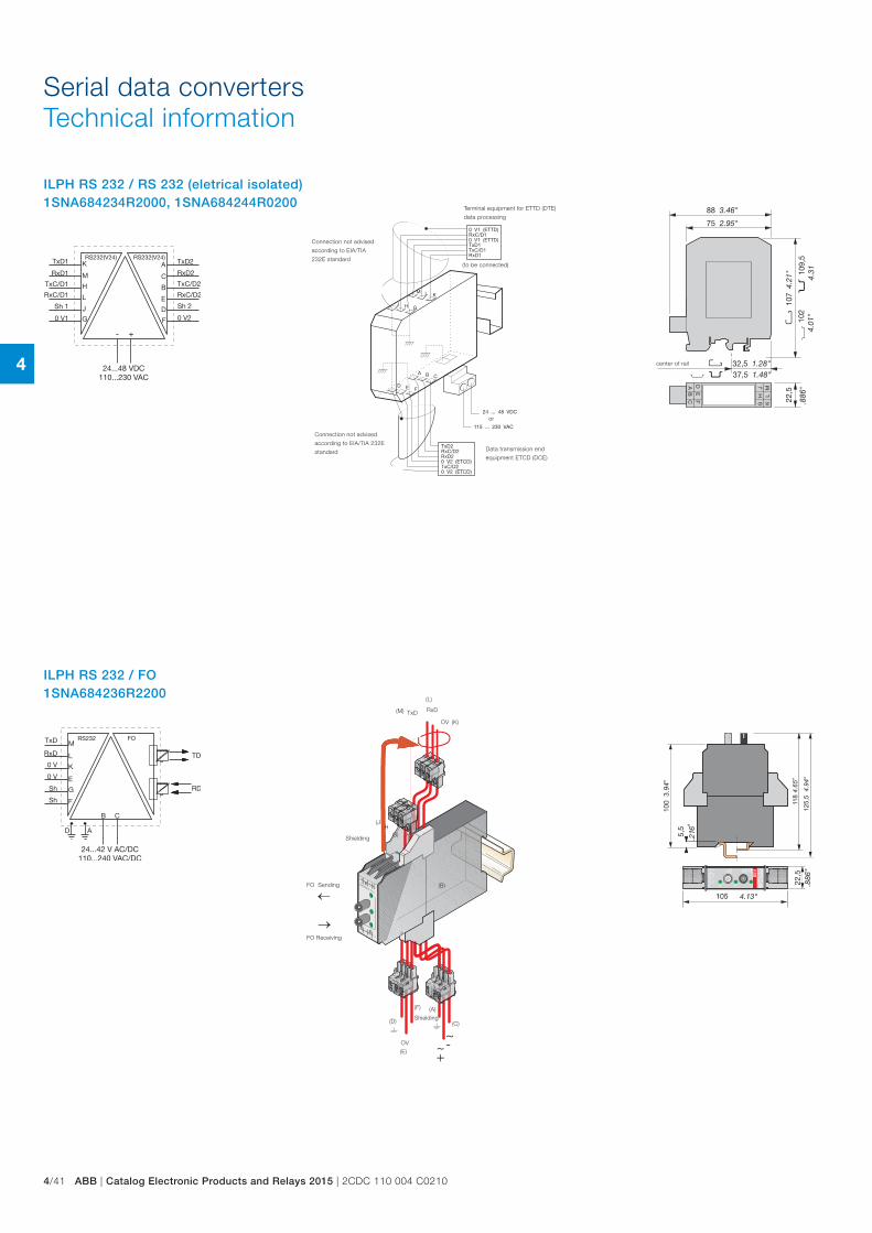
4
4/41 ABB | Catalog Electronic Products and Relays 2015 | 2CDC 110 004 C0210
ILPH RS 232 / RS 232 (eletrical isolated) 1SNA684234R2000, 1SNA684244R0200
Serial data convertersTechnical information
Connection not advised
according to EIA/TIA 232E
standard
or
Connection not advised
according to EIA/TIA
232E standard(to be connected)
Terminal equipment for ETTD (DTE)
data processing
Data transmission end
equipment ETCD (DCE)
center of rail
ILPH RS 232 / FO 1SNA684236R2200
RxD
OV
TxD
OV
←
→
~+
~-
(L)
(K)
(M)
(JH
G)
(E)
(F)
(D)
(B)
(C)
(A)
Shielding
FO Sending
FO Receiving
Shielding
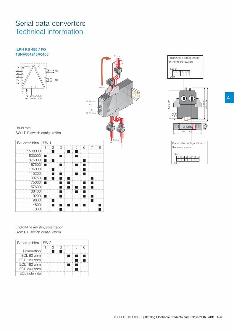
4
2CDC 110 004 C0210 | Catalog Electronic Products and Relays 2015 | ABB 4/42
Serial data convertersTechnical information
ILPH RS 485 / FO 1SNA684246R0400
OV
D - D +
Shielding
~-
~+
Shielding
OV
←
→
FO Sending
FO Receiving
Baud rate configuration of the micro-switch
Polarization configuration of the micro-switch
1
1
2
2
SW 1
SW 2
OFF
OFF
6
6
3
3
74
4
85
5
Baudrate bit/s SW 11 2 3 4 5 6 7 8
1500000 M M M500000 M M M375000 M M M187500 M M M M136000 M M115200 M M M M
93750 M M M M M75000 M M M M M57600 M M M M M38400 M M M19200 M M M M9600 M M4800 M M M M M M300 M M
Baudrate bit/s SW 21 2 3 4 5 6
Polarization M MEOL 60 ohm M M M
EOL 120 ohm M MEOL 180 ohm M MEOL 240 ohm MEOL indefinite
Baud rate: SW1 DIP switch configuration
End-of-line resistor, polarization: SW2 DIP switch configuration
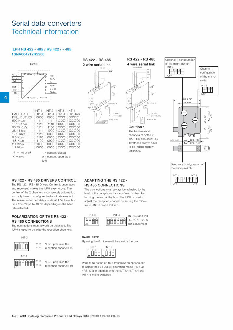
4
4/43 ABB | Catalog Electronic Products and Relays 2015 | 2CDC 110 004 C0210
Serial data convertersTechnical information
center of rail
ILPH RS 422 - 485 / RS 422 / - 485 1SNA684212R2200
Nu = not used X = zero
1 = contact closed 0 = contact open (aus) (off)
OFF
1 2 3 4
1 2 3 4 5 6
OFF
INT 3
INT 4
INT 3.1
INT 3.2
INT 4.1
INT 4.2
OFF
OFF
INT 31 2 3 4 5 6
INT 41 2 3 4
OFF
1 2 3 4
OFF
INT 1 INT 2"ON", polarizes the reception channel Rx2
"ON", polarizes the reception channel Rx1
RS 422 - RS 485 DRIVERS CONTROLThe RS 422 - RS 485 Drivers Control (transmitters and receivers) makes the ILPH easy to use. The control of the 2 channels is completely automatic ; you only have to configure the baud rate needed. The minimum turn off delay is about 1.5 character/time from 27 µs to 10 ms depending on the baud rate selected.
POLARIZATION OF THE RS 422 - RS 485 CONNECTIONSThe connections must always be polarized. The ILPH is used to polarize the reception channels:
ADAPTING THE RS 422 - RS 485 CONNECTIONSThe connections must always be adjusted to the level of the reception channel of each subscriber forming the end of the bus. The ILPH is used to adjust the reception channel by setting the micro-switch INT 3.3 and INT 4.3.
INT 3.3 and INT 4.3 "ON" 120 Ω set adjustment
Caution : The transmission channels of both RS 422 - RS 485 serial link interfaces always have to be independently polarized.
RS 422 - RS 485 4 wire serial link
RS 422 - RS 485 2 wire serial link
24 V DC
power supply
Connector J1
24 V DC
power supply
Connector J1
INT 1 INT 2 INT 3 INT 4BAUD RATE 1234 1234 1234 123456FULL DUPLEX 0000 0000 XXX1 XXX101500 Kb/s 1111 1111 XXX0 XXX000187.5 Kb/s 1111 1110 XXX0 XXX00093.75 Kb/s 1111 1100 XXX0 XXX00038.4 Kb/s 1111 1000 XXX0 XXX00019.2 Kb/s 1111 0000 XXX0 XXX0009.6 Kb/s 1110 0000 XXX0 XXX0004.8 Kb/s 1100 0000 XXX0 XXX0002.4 Kb/s 1000 0000 XXX0 XXX0001.2 Kb/s 0000 0000 XXX0 XXX000
1 2 3 4
BAUD RATEBy using the 8 micro-switches inside the box.
Permits to define up to 8 transmission speeds and to select the Full Duplex operation mode (RS 422 / RS 422) in addition with the INT 3.4 INT 4.4 and INT 4.5 micro switches.
Baud rate configuration of the micro-switch
Channel 1 configuration of the micro-switch
Channel 1 configuration of the micro-switch
1
1
1
2
2
2
INT 1
INT 4
INT 4
OFF
OFF
OFF
OFF
INT 223
3
3
34
4
4
41
1
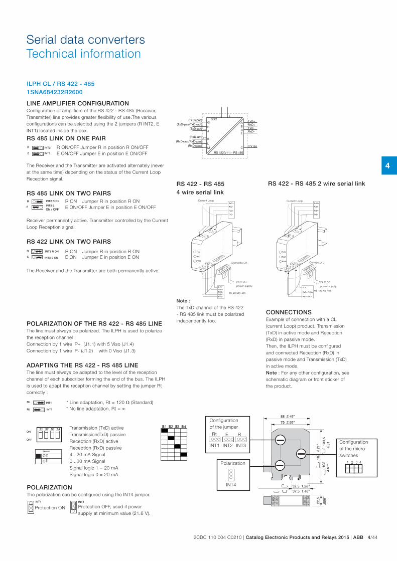
4
2CDC 110 004 C0210 | Catalog Electronic Products and Relays 2015 | ABB 4/44
Serial data convertersTechnical information
Polarization
INT4
Rt
INT1 INT2 INT3
E R
Configuration of the jumper
LINE AMPLIFIER CONFIGURATIONConfiguration of amplifiers of the RS 422 - RS 485 (Receiver, Transmitter) line provides greater flexibility of use.The various configurations can be selected using the 2 jumpers (R INT2, E INT1) located inside the box.
RS 485 LINK ON ONE PAIR
The Receiver and the Transmitter are activated alternately (never at the same time) depending on the status of the Current Loop Reception signal.
RS 485 LINK ON TWO PAIRS
Receiver permanently active. Transmitter controlled by the Current Loop Reception signal.
RS 422 LINK ON TWO PAIRS
The Receiver and the Transmitter are both permanently active.
ILPH CL / RS 422 - 485 1SNA684232R2600
INT4
R
E
INT2
INT3
R
E
INT2 R ON
INT3 E
ON / OFF
R
E
INT2 R ON
INT3 E ON
Rt
Rt INT1
INT1
S1 S2 S3 S4ON
OFF
INT4
onoff
Protection ON Protection OFF, used if power supply at minimum value (21.6 V).
E ON/OFF Jumper E in position E ON/OFFR ON/OFF Jumper R in position R ON/OFF
R ON Jumper R in position R ONE ON/OFF Jumper E in position E ON/OFF
R ON Jumper R in position R ONE ON Jumper E in position E ON
POLARIZATION OF THE RS 422 - RS 485 LINEThe line must always be polarized. The ILPH is used to polarize the reception channel :Connection by 1 wire P+ (J1.1) with 5 Viso (J1.4)Connection by 1 wire P- (J1.2) with 0 Viso (J1.3)
ADAPTING THE RS 422 - RS 485 LINEThe line must always be adapted to the level of the reception channel of each subscriber forming the end of the bus. The ILPH is used to adapt the reception channel by setting the jumper Rt correctly :
* Line adaptation, Rt = 120 Ω (Standard)* No line adaptation, Rt = ∞
Transmission (TxD) active Transmission(TxD) passive Reception (RxD) active Reception (RxD) passive 4...20 mA Signal 0...20 mA Signal Signal logic 1 = 20 mA Signal logic 0 = 20 mA
Legend
RS 422 - RS 485 2 wire serial link
CONNECTIONSExample of connection with a CL (current Loop) product, Transmission (TxD) in active mode and Reception (RxD) in passive mode.Then, the ILPH must be configured and connected Reception (RxD) in passive mode and Transmission (TxD) in active mode.Note : For any other configuration, see schematic diagram or front sticker of the product.
Current Loop
Connector J1
24 V DC
power supply
Note : The TxD channel of the RS 422 - RS 485 link must be polarized independently too.
RS 422 - RS 485 4 wire serial link
Current Loop
Connector J1
24 V DC
power supply
POLARIZATIONThe polarization can be configured using the INT4 jumper.
1 2 3 4
Configuration of the micro-switches
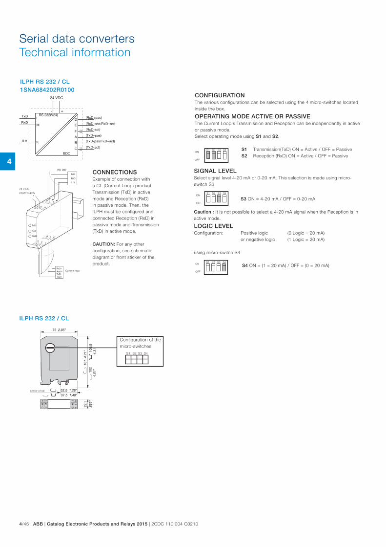
4
4/45 ABB | Catalog Electronic Products and Relays 2015 | 2CDC 110 004 C0210
Serial data convertersTechnical information
ILPH RS 232 / CL 1SNA684202R0100
ON
OFF
CONFIGURATIONThe various configurations can be selected using the 4 micro-switches located inside the box.
OPERATING MODE ACTIVE OR PASSIVEThe Current Loop's Transmission and Reception can be independently in active or passive mode.Select operating mode using S1 and S2.
S1 Transmission(TxD) ON = Active / OFF = Passive S2 Reception (RxD) ON = Active / OFF = Passive
S1 S2 S3 S4
ON
OFF
ON
OFF
SIGNAL LEVELSelect signal level 4-20 mA or 0-20 mA. This selection is made using micro-switch S3
S3 ON = 4-20 mA / OFF = 0-20 mA
Caution : It is not possible to select a 4-20 mA signal when the Reception is in active mode.
LOGIC LEVELConfiguration: Positive logic (0 Logic = 20 mA) or negative logic (1 Logic = 20 mA)
using micro-switch S4
S4 ON = (1 = 20 mA) / OFF = (0 = 20 mA)
S1 S2 S3 S4
S1 S2 S3 S4
Current loop
24 V DC
power supply
CONNECTIONSExample of connection with a CL (Current Loop) product, Transmission (TxD) in active mode and Reception (RxD) in passive mode. Then, the ILPH must be configured and connected Reception (RxD) in passive mode and Transmission (TxD) in active mode. CAUTION: For any other configuration, see schematic diagram or front sticker of the product.
ILPH RS 232 / CL
center of rail
S1 S2 S3 S4
Configuration of the micro-switches
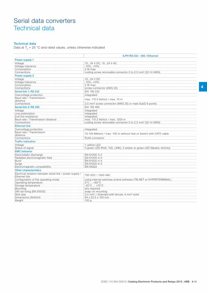
4
2CDC 110 004 C0210 | Catalog Electronic Products and Relays 2015 | ABB 4/46
Serial data convertersTechnical data
Technical dataData at Ta = 25 °C and rated values, unless otherwise indicated
ILPH RS 232 - 485 / Ethernet
Power supply 1Voltage 10...34 V DC, 10...24 V ACVoltage tolerance -10%, +10%Consumption 2 W maxConnections coding screw removable connector 0 to 2.5 mm² (22-14 AWG)Power supply 2Voltage 10...34 V DCVoltage tolerance -10%, +10%Consumption 2 W maxConnections screw connector (AWG 20)Serial link 1: RS 232 EIA RS 232Overvoltage protection integratedBaud rate / Transmission distance max. 115.2 kbits/s / max. 15 m
Connections 2.5 mm² screw connector (AWG 20) or male SubD 9 pointsSerial link 2: RS 485 EIA RS 485Voltage integratedLine polarization integratedEnd line resistance integratedBaud rate / Transmission distance max. 115.2 kbits/s / max. 1200 mConnections coding screw removable connector 0 to 2.5 mm² (22-14 AWG)Ethernet linkOvervoltage protection integratedBaud rate / Transmission distance 10-100 Mbits/s / max. 100 m without Hub or Switch with CAT5 cable
Connections RJ45 connectorTraffic indicationVoltage 1 yellow LEDStatus of signal 3 green LED (RxD, TxD, LINK), 2 amber or green LED (Speed, Activity)EMC behaviorElectrostatic discharge EN 61000-4-2Radiated electromagnetic field EN 61000-4-3Burst EN 61000-4-4Surge EN 61000-4-5Electromagnetic compatibility EN 55022Other characteristicsElectrical isolation between serial link / power supply / Ethernet link 750 VDC / 1500 VAC
Configuration of the operating mode using internal switches or/and software (TELNET or HYPERTERMINAL)Operating temperature 0°C ... +60°CStorage temperature -20°C ... +70°CMounting any requiredDIN rail fixing (EN 50002) snap-on mountingWire size 2.5 mm² / stranded with ferrule, 4 mm² solidDimensions (WxDxH) 94 x 22.5 x 100 mmWeight 120 g
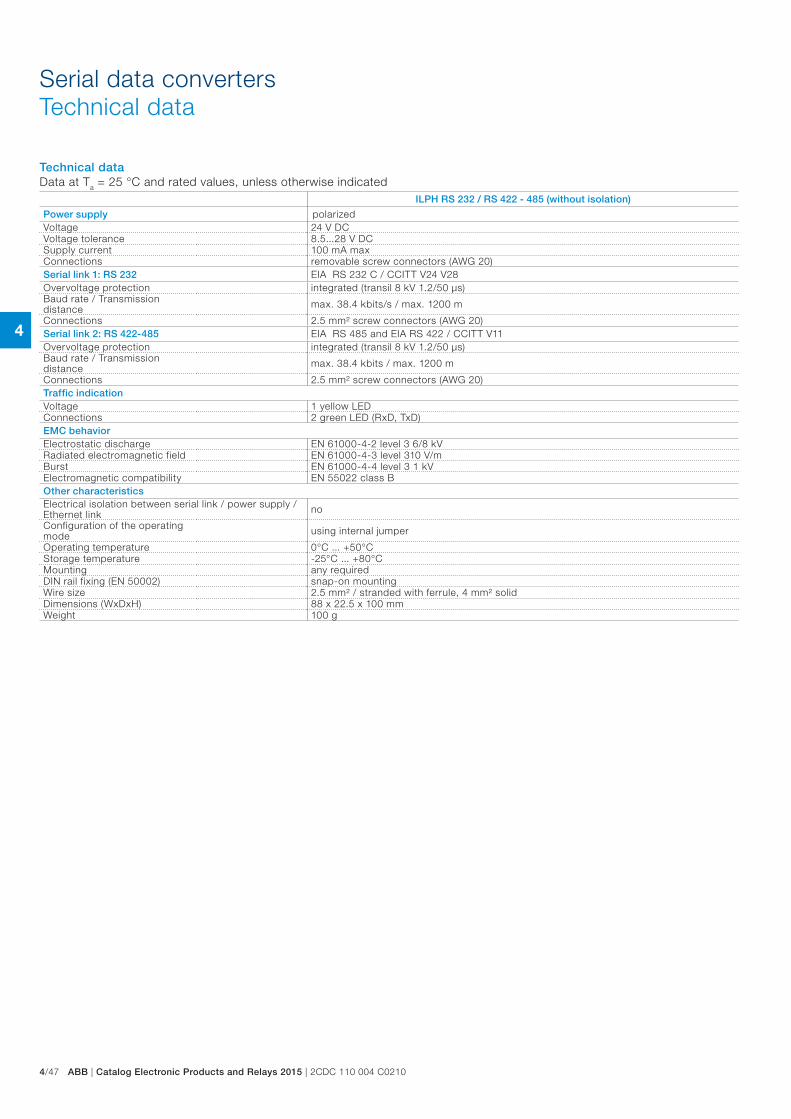
4
4/47 ABB | Catalog Electronic Products and Relays 2015 | 2CDC 110 004 C0210
Serial data convertersTechnical data
Technical dataData at Ta = 25 °C and rated values, unless otherwise indicated
ILPH RS 232 / RS 422 - 485 (without isolation)
Power supply polarizedVoltage 24 V DCVoltage tolerance 8.5...28 V DCSupply current 100 mA maxConnections removable screw connectors (AWG 20)Serial link 1: RS 232 EIA RS 232 C / CCITT V24 V28Overvoltage protection integrated (transil 8 kV 1.2/50 µs)Baud rate / Transmission distance max. 38.4 kbits/s / max. 1200 m
Connections 2.5 mm² screw connectors (AWG 20)Serial link 2: RS 422-485 EIA RS 485 and EIA RS 422 / CCITT V11Overvoltage protection integrated (transil 8 kV 1.2/50 µs)Baud rate / Transmission distance max. 38.4 kbits / max. 1200 m
Connections 2.5 mm² screw connectors (AWG 20)Traffic indicationVoltage 1 yellow LEDConnections 2 green LED (RxD, TxD)EMC behaviorElectrostatic discharge EN 61000-4-2 level 3 6/8 kVRadiated electromagnetic field EN 61000-4-3 level 310 V/mBurst EN 61000-4-4 level 3 1 kVElectromagnetic compatibility EN 55022 class BOther characteristicsElectrical isolation between serial link / power supply / Ethernet link no
Configuration of the operating mode using internal jumper
Operating temperature 0°C ... +50°CStorage temperature -25°C ... +80°CMounting any requiredDIN rail fixing (EN 50002) snap-on mountingWire size 2.5 mm² / stranded with ferrule, 4 mm² solidDimensions (WxDxH) 88 x 22.5 x 100 mmWeight 100 g
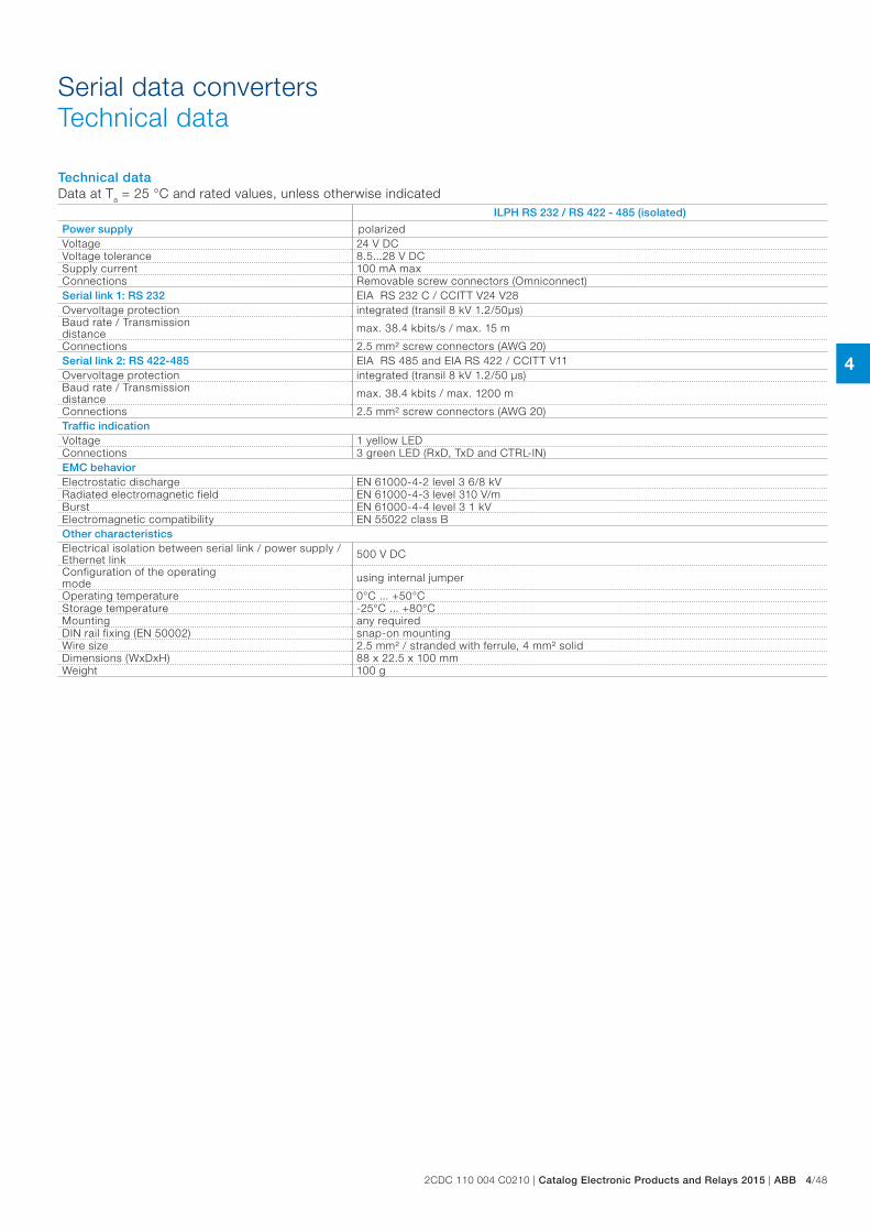
4
2CDC 110 004 C0210 | Catalog Electronic Products and Relays 2015 | ABB 4/48
Serial data convertersTechnical data
Technical dataData at Ta = 25 °C and rated values, unless otherwise indicated
ILPH RS 232 / RS 422 - 485 (isolated)
Power supply polarizedVoltage 24 V DCVoltage tolerance 8.5...28 V DCSupply current 100 mA maxConnections Removable screw connectors (Omniconnect)Serial link 1: RS 232 EIA RS 232 C / CCITT V24 V28Overvoltage protection integrated (transil 8 kV 1.2/50µs)Baud rate / Transmission distance max. 38.4 kbits/s / max. 15 m
Connections 2.5 mm² screw connectors (AWG 20)Serial link 2: RS 422-485 EIA RS 485 and EIA RS 422 / CCITT V11Overvoltage protection integrated (transil 8 kV 1.2/50 µs)Baud rate / Transmission distance max. 38.4 kbits / max. 1200 m
Connections 2.5 mm² screw connectors (AWG 20)Traffic indicationVoltage 1 yellow LEDConnections 3 green LED (RxD, TxD and CTRL-IN)EMC behaviorElectrostatic discharge EN 61000-4-2 level 3 6/8 kVRadiated electromagnetic field EN 61000-4-3 level 310 V/mBurst EN 61000-4-4 level 3 1 kVElectromagnetic compatibility EN 55022 class BOther characteristicsElectrical isolation between serial link / power supply / Ethernet link 500 V DC
Configuration of the operating mode using internal jumper
Operating temperature 0°C ... +50°CStorage temperature -25°C ... +80°CMounting any requiredDIN rail fixing (EN 50002) snap-on mountingWire size 2.5 mm² / stranded with ferrule, 4 mm² solidDimensions (WxDxH) 88 x 22.5 x 100 mmWeight 100 g
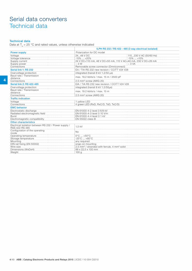
4
4/49 ABB | Catalog Electronic Products and Relays 2015 | 2CDC 110 004 C0210
Serial data convertersTechnical data
Technical dataData at Ta = 25 °C and rated values, unless otherwise indicated
ILPH RS 232 / RS 422 - 485 (3 way electrical isolated)
Power supply Polarization for DC modelVoltage 24...48 V DC 115...230 V AC (50/60 Hz)Voltage tolerance -15% ... +20% -15% ... +15%Supply current 24 V DC<110 mA, 48 V DC<55 mA, 115 V AC<40 mA, 230 V DC<26 mASupply power ~ 3 W ~ 3 VAConnections Removable screw connector (Omniconnect)Serial link 1: RS 232 EA / TIA RS 232 new revision / CCITT V24 V28Overvoltage protection integrated (transil 8 kV 1.2/50 μs)Baud rate / Transmission distance max. 19,2 kbits/s / max. 15 m / 2500 pF
Connections 2.5 mm² screw (AWG 20)Serial link 2: RS 422-485 EIA / TIA RS 232 new revision / CCITT V24 V28Overvoltage protection integrated (transil 8 kV 1.2/50μs)Baud rate / Transmission distance max. 19.2 kbits/s / max. 15 m
Connections 2.5 mm² screw (AWG 20)Traffic indicationVoltage 1 yellow LEDConnections 4 green LED (RxD, RxC/D, TxD, TxC/D)EMC behaviorElectrostatic discharge EN 61000-4-2 level 3 6/8 kVRadiated electromagnetic field EN 61000-4-3 level 3 10 V/mBurst EN 61000-4-4 level 3 1 kVElectromagnetic compatibility EN 55022 class BOther characteristicsElectrical isolation between RS 232 / Power supply / RSS 422-RS 485 1,5 kV
Configuration of the operating mode No
Operating temperature 0°C ... +50°CStorage temperature -25°C ... +80°CMounting any requiredDIN rail fixing (EN 50002) snap-on mountingWire size 2.5 mm² / stranded with ferrule, 4 mm² solidDimensions (WxDxH) 88 x 22,5 x 100 mmWeight 100 g
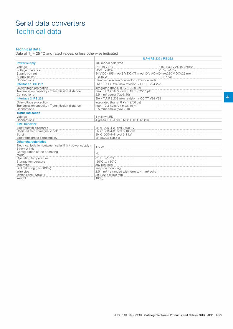
4
2CDC 110 004 C0210 | Catalog Electronic Products and Relays 2015 | ABB 4/50
Serial data convertersTechnical data
Technical dataData at Ta = 25 °C and rated values, unless otherwise indicated
ILPH RS 232 / RS 232
Power supply DC model polarizedVoltage 24...48 V DC 115...230 V AC (50/60Hz)Voltage tolerance -15%...+20% -15%...+15%Supply current 24 V DC<155 mA;48 V DC<77 mA;110 V AC<40 mA;230 V DC<26 mASupply power ~ 3.15 W ~ 3.15 VAConnections Removable screw connector (Omniconnect)Interface 1: RS 232 EIA / TIA RS 232 new revision / CCITT V24 V28Overvoltage protection integrated (transil 8 kV 1.2/50 µs)Transmission capacity / Transmission distance max. 19.2 kbits/s / max. 15 m / 2500 pFConnections 2.5 mm² screw (AWG 20)Interface 2: RS 232 EIA / TIA RS 232 new revision / CCITT V24 V28Overvoltage protection integrated (transil 8 kV 1.2/50 µs)Transmission capacity / Transmission distance max. 19.2 kbits/s / max. 15 mConnections 2.5 mm² screw (AWG 20)Traffic indicationVoltage 1 yellow LEDConnections 4 green LED (RxD, RxC/D, TxD, TxC/D)EMC behaviorElectrostatic discharge EN 61000-4-2 level 3 6/8 kVRadiated electromagnetic field EN 61000-4-3 level 3 10 V/mBurst EN 61000-4-4 level 3 1 kVElectromagnetic compatibility EN 55022 class BOther characteristicsElectrical isolation between serial link / power supply / Ethernet link 1.5 kV
Configuration of the operating mode No
Operating temperature 0°C ... +50°CStorage temperature -25°C ... +80°CMounting any requiredDIN rail fixing (EN 50002) snap-on mountingWire size 2.5 mm² / stranded with ferrule, 4 mm² solidDimensions (WxDxH) 88 x 22.5 x 100 mmWeight 100 g
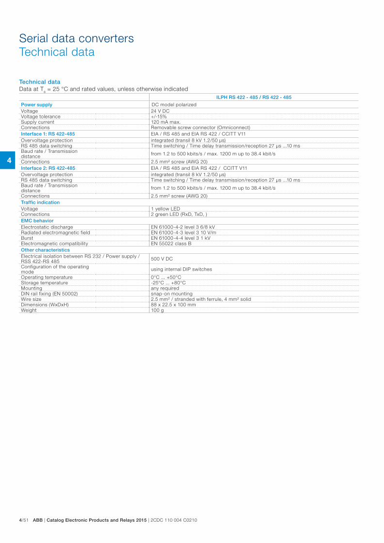
4
4/51 ABB | Catalog Electronic Products and Relays 2015 | 2CDC 110 004 C0210
Serial data convertersTechnical data
Technical dataData at Ta = 25 °C and rated values, unless otherwise indicated
ILPH RS 422 - 485 / RS 422 - 485
Power supply DC model polarizedVoltage 24 V DCVoltage tolerance +/-15%Supply current 120 mA max.Connections Removable screw connector (Omniconnect)Interface 1: RS 422-485 EIA / RS 485 and EIA RS 422 / CCITT V11Overvoltage protection integrated (transil 8 kV 1.2/50 µs)RS 485 data switching Time switching / Time delay transmission/reception 27 µs ...10 msBaud rate / Transmission distance from 1.2 to 500 kbits/s / max. 1200 m up to 38.4 kbit/s
Connections 2.5 mm² screw (AWG 20)Interface 2: RS 422-485 EIA / RS 485 and EIA RS 422 / CCITT V11Overvoltage protection integrated (transil 8 kV 1.2/50 µs)RS 485 data switching Time switching / Time delay transmission/reception 27 µs ...10 msBaud rate / Transmission distance from 1.2 to 500 kbits/s / max. 1200 m up to 38.4 kbit/s
Connections 2.5 mm² screw (AWG 20)Traffic indicationVoltage 1 yellow LEDConnections 2 green LED (RxD, TxD, )EMC behaviorElectrostatic discharge EN 61000-4-2 level 3 6/8 kVRadiated electromagnetic field EN 61000-4-3 level 3 10 V/mBurst EN 61000-4-4 level 3 1 kVElectromagnetic compatibility EN 55022 class BOther characteristicsElectrical isolation between RS 232 / Power supply / RSS 422-RS 485 500 V DC
Configuration of the operating mode using internal DIP switches
Operating temperature 0°C ... +50°CStorage temperature -25°C ... +80°CMounting any requiredDIN rail fixing (EN 50002) snap-on mountingWire size 2.5 mm² / stranded with ferrule, 4 mm² solidDimensions (WxDxH) 88 x 22.5 x 100 mmWeight 100 g
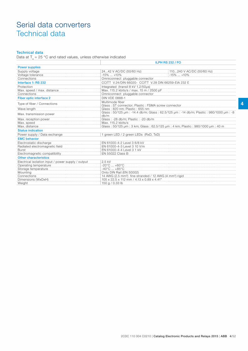
4
2CDC 110 004 C0210 | Catalog Electronic Products and Relays 2015 | ABB 4/52
Serial data convertersTechnical data
Technical dataData at Ta = 25 °C and rated values, unless otherwise indicated
ILPH RS 232 / FO
Power suppliesSupply voltage 24...42 V AC/DC (50/60 Hz) 110...240 V AC/DC (50/60 Hz)Voltage tolerance -15% ... +10% -15% ... +10%Connections Omniconnect pluggable connectorInterface 1: RS 232 CCITT V.24/DIN 66020- CCITT V.28 DIN 66259-EIA 232 EProtection Integrated (transil 8 kV 1.2/50µs)Max. speed / max. distance Max. 115.2 kbits/s / max. 15 m / 2500 pFConnections Omniconnect pluggable connectorFiber optic interface 2 DIN VDE 0888-1
Type of fiber / Connections Multimode fiber Glass : ST connector; Plastic : FSMA screw connector
Wave length Glass : 820 nm; Plastic : 655 nm
Max. transmission power Glass : 50/125 µm : -14.4 db/m; Glass : 62.5/125 µm : -14 db/m; Plastic : 980/1000 µm : -8 db/m
Max. reception power Glass : -28 db/m; Plastic : -20 db/mMax. speed Max. 115.2 kbits/sMax. distance Glass : 50/125 µm : 3 km; Glass : 62.5/125 µm : 4 km; Plastic : 980/1000 µm : 40 mStatus indicationPower supply / Data exchange 1 green LED / 2 green LEDs (RxD, TxD)EMC behaviorElectrostatic discharge EN 61000-4-2 Level 3 6/8 kVRadiated electromagnetic field EN 61000-4-3 Level 3 10 V/mBurst EN 61000-4-4 Level 3 1 kVElectromagnetic compatibility EN 55022 Class BOther characteristicsElectrical isolation input / power supply / output 2.5 kVOperating temperature -20°C ... +60°CStorage temperature -40°C ... +85°CMounting Onto DIN Rail (EN 50002)Connections 14 AWG (2.5 mm²) fine stranded / 12 AWG (4 mm²) rigidDimensions (WxDxH) 105 x 22.5 x 112 mm / 4.13 x 0.89 x 4.41"Weight 150 g / 0.33 lb
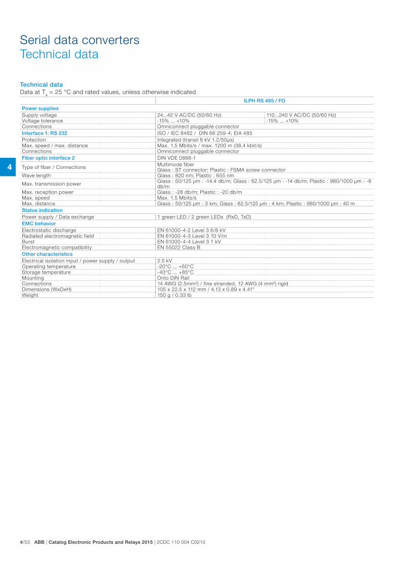
4
4/53 ABB | Catalog Electronic Products and Relays 2015 | 2CDC 110 004 C0210
Serial data convertersTechnical data
Technical dataData at Ta = 25 °C and rated values, unless otherwise indicated
ILPH RS 485 / FO
Power suppliesSupply voltage 24...42 V AC/DC (50/60 Hz) 110...240 V AC/DC (50/60 Hz)Voltage tolerance -15% ... +10% -15% ... +10%Connections Omniconnect pluggable connectorInterface 1: RS 232 ISO / IEC 8482 / DIN 66 259-4; EIA 485Protection Integrated (transil 8 kV 1.2/50µs)Max. speed / max. distance Max. 1.5 Mbits/s / max. 1200 m (38.4 kbit/s)Connections Omniconnect pluggable connectorFiber optic interface 2 DIN VDE 0888-1
Type of fiber / Connections Multimode fiber Glass : ST connector; Plastic : FSMA screw connector
Wave length Glass : 820 nm; Plastic : 655 nm
Max. transmission power Glass : 50/125 µm : -14.4 db/m; Glass : 62.5/125 µm : -14 db/m; Plastic : 980/1000 µm : -8 db/m
Max. reception power Glass : -28 db/m; Plastic : -20 db/mMax. speed Max. 1.5 Mbits/sMax. distance Glass : 50/125 µm : 3 km; Glass : 62.5/125 µm : 4 km; Plastic : 980/1000 µm : 40 mStatus indicationPower supply / Data exchange 1 green LED / 2 green LEDs (RxD, TxD)EMC behaviorElectrostatic discharge EN 61000-4-2 Level 3 6/8 kVRadiated electromagnetic field EN 61000-4-3 Level 3 10 V/mBurst EN 61000-4-4 Level 3 1 kVElectromagnetic compatibility EN 55022 Class BOther characteristicsElectrical isolation input / power supply / output 2.5 kVOperating temperature -20°C ... +60°CStorage temperature -40°C ... +85°CMounting Onto DIN RailConnections 14 AWG (2.5mm²) / fine stranded, 12 AWG (4 mm²) rigidDimensions (WxDxH) 105 x 22.5 x 112 mm / 4.13 x 0.89 x 4.41"Weight 150 g / 0.33 lb
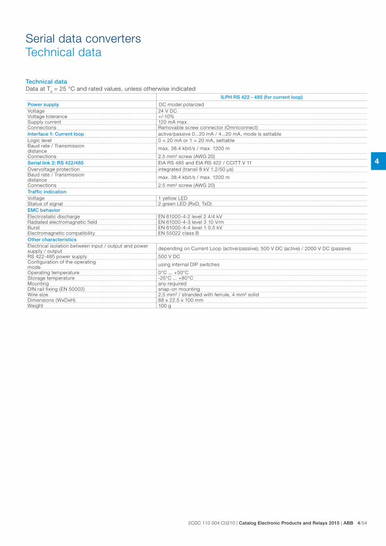
4
2CDC 110 004 C0210 | Catalog Electronic Products and Relays 2015 | ABB 4/54
Serial data convertersTechnical data
Technical dataData at Ta = 25 °C and rated values, unless otherwise indicated
ILPH RS 422 - 485 (for current loop)
Power supply DC model polarizedVoltage 24 V DCVoltage tolerance +/-10%Supply current 120 mA max.Connections Removable screw connector (Omniconnect)Interface 1: Current loop active/passive 0...20 mA / 4...20 mA, mode is settableLogic level 0 = 20 mA or 1 = 20 mA, settableBaud rate / Transmission distance max. 38.4 kbit/s / max. 1200 m
Connections 2.5 mm² screw (AWG 20)Serial link 2: RS 422/485 EIA RS 485 and EIA RS 422 / CCITT V 11Overvoltage protection integrated (transil 8 kV 1.2/50 µs)Baud rate / Transmission distance max. 38.4 kbit/s / max. 1200 m
Connections 2.5 mm² screw (AWG 20)Traffic indicationVoltage 1 yellow LEDStatus of signal 2 green LED (RxD, TxD)EMC behaviorElectrostatic discharge EN 61000-4-2 level 2 4/4 kVRadiated electromagnetic field EN 61000-4-3 level 3 10 V/mBurst EN 61000-4-4 level 1 0.5 kVElectromagnetic compatibility EN 55022 class BOther characteristicsElectrical isolation between input / output and power supply / output depending on Current Loop (active/passive); 500 V DC (active) / 2000 V DC (passive)
RS 422-485 power supply 500 V DCConfiguration of the operating mode using internal DIP switches
Operating temperature 0°C ... +50°CStorage temperature -25°C ... +80°CMounting any requiredDIN rail fixing (EN 50002) snap-on mountingWire size 2.5 mm² / stranded with ferrule, 4 mm² solidDimensions (WxDxH) 88 x 22.5 x 100 mmWeight 100 g
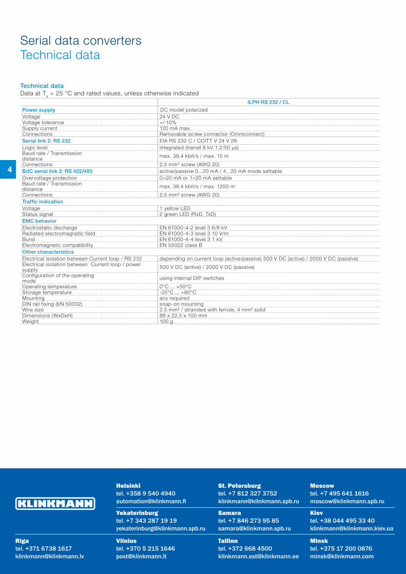
4
Serial data convertersTechnical data
Technical dataData at Ta = 25 °C and rated values, unless otherwise indicated
ILPH RS 232 / CL
Power supply DC model polarizedVoltage 24 V DCVoltage tolerance +/-10%Supply current 120 mA max.Connections Removable screw connector (Omniconnect)Serial link 2: RS 232 EIA RS 232 C / CCITT V 24 V 28Logic level integrated (transil 8 kV 1.2/50 µs)Baud rate / Transmission distance max. 38.4 kbit/s / max. 15 m
Connections 2.5 mm² screw (AWG 20)BdC serial link 2: RS 422/485 active/passive 0...20 mA / 4...20 mA mode settableOvervoltage protection 0=20 mA or 1=20 mA settableBaud rate / Transmission distance max. 38.4 kbit/s / max. 1200 m
Connections 2.5 mm² screw (AWG 20)Traffic indicationVoltage 1 yellow LEDStatus signal 2 green LED (RxD, TxD)EMC behaviorElectrostatic discharge EN 61000-4-2 level 3 6/8 kVRadiated electromagnetic field EN 61000-4-3 level 3 10 V/mBurst EN 61000-4-4 level 3 1 kVElectromagnetic compatibility EN 55022 class BOther characteristicsElectrical isolation between Current loop / RS 232 depending on current loop (active/passive) 500 V DC (active) / 2000 V DC (passive)Electrical isolation between Current loop / power supply 500 V DC (active) / 2000 V DC (passive)
Configuration of the operating mode using internal DIP switches
Operating temperature 0°C ... +50°CStorage temperature -25°C ... +80°CMounting any requiredDIN rail fixing (EN 50002) snap-on mountingWire size 2.5 mm² / stranded with ferrule, 4 mm² solidDimensions (WxDxH) 88 x 22.5 x 100 mmWeight 100 g
Samaratel. +7 846 273 95 [email protected]
Yekaterinburgtel. +7 343 287 19 [email protected]
St. Petersburgtel. +7 812 327 [email protected]
Moscowtel. +7 495 641 [email protected]
Helsinkitel. +358 9 540 [email protected]
Vilniustel. +370 5 215 [email protected]
Rigatel. +371 6738 [email protected]
Мinsktel. +375 17 200 [email protected]
Tallinntel. +372 668 [email protected]
Кievtel. +38 044 495 33 [email protected]