Embed Size (px)
Citation preview
Proceedings of the MEDSI 2014 Conference
Melbourne, Australia - October 2014
1
Variable Aperture Photon Mask (Slits) for Canted Undulator
Beamlines at the Advanced Photon Source
Oliver Schmidt, Mohan Ramanathan, Dana Capatina, William Toter, Soonhong Lee Advanced Photon Source, Argonne National Laboratory
Lemont, IL 60148, USA
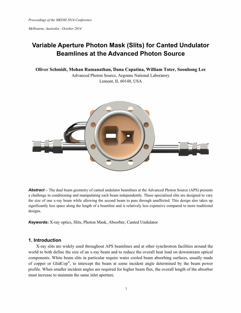
Abstract – The dual beam geometry of canted undulator beamlines at the Advanced Photon Source (APS) presents a challenge in conditioning and manipulating each beam independently. These specialized slits are designed to vary the size of one x-ray beam while allowing the second beam to pass through unaffected. This design also takes up significantly less space along the length of a beamline and is relatively less expensive compared to more traditional designs. Keywords: X-ray optics, Slits, Photon Mask, Absorber, Canted Undulator 1. Introduction
X-ray slits are widely used throughout APS beamlines and at other synchrotron facilities around the world to both define the size of an x-ray beam and to reduce the overall heat load on downstream optical components. White beam slits in particular require water cooled beam absorbing surfaces, usually made of copper or GlidCop®, to intercept the beam at some incident angle determined by the beam power profile. When smaller incident angles are required for higher beam flux, the overall length of the absorber must increase to maintain the same inlet aperture.
2
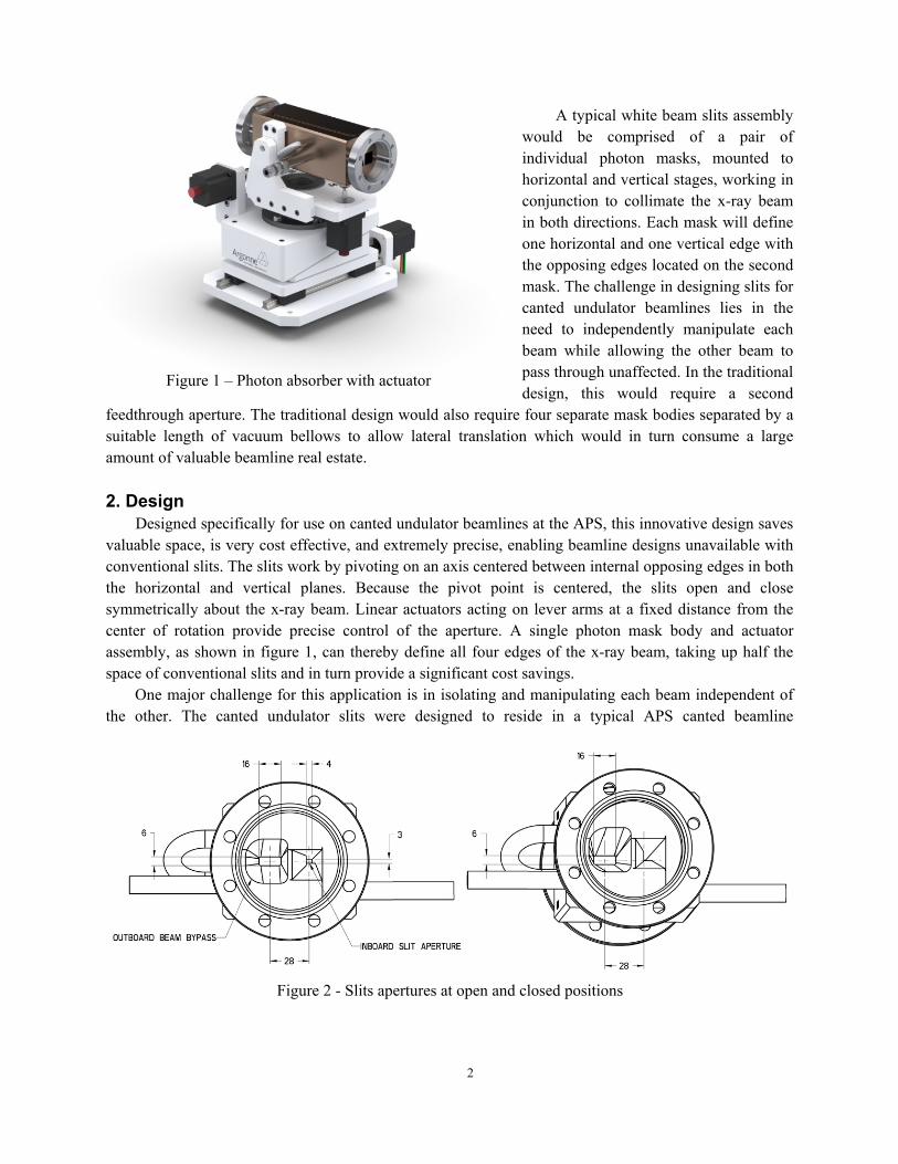
Figure 1 – Photon absorber with actuator
A typical white beam slits assembly would be comprised of a pair of individual photon masks, mounted to horizontal and vertical stages, working in conjunction to collimate the x-ray beam in both directions. Each mask will define one horizontal and one vertical edge with the opposing edges located on the second mask. The challenge in designing slits for canted undulator beamlines lies in the need to independently manipulate each beam while allowing the other beam to pass through unaffected. In the traditional design, this would require a second
feedthrough aperture. The traditional design would also require four separate mask bodies separated by a suitable length of vacuum bellows to allow lateral translation which would in turn consume a large amount of valuable beamline real estate.
2. Design
Designed specifically for use on canted undulator beamlines at the APS, this innovative design saves valuable space, is very cost effective, and extremely precise, enabling beamline designs unavailable with conventional slits. The slits work by pivoting on an axis centered between internal opposing edges in both the horizontal and vertical planes. Because the pivot point is centered, the slits open and close symmetrically about the x-ray beam. Linear actuators acting on lever arms at a fixed distance from the center of rotation provide precise control of the aperture. A single photon mask body and actuator assembly, as shown in figure 1, can thereby define all four edges of the x-ray beam, taking up half the space of conventional slits and in turn provide a significant cost savings.
One major challenge for this application is in isolating and manipulating each beam independent of the other. The canted undulator slits were designed to reside in a typical APS canted beamline
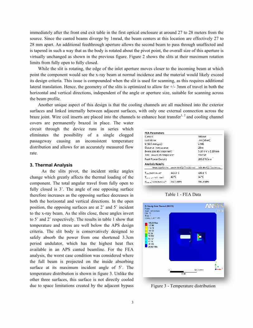
Figure 2 - Slits apertures at open and closed positions
3
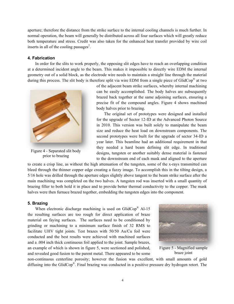
Table 1 - FEA Data
immediately after the front end exit table in the first optical enclosure at around 27 to 28 meters from the source. Since the canted beams diverge by 1mrad, the beam centers at this location are effectively 27 to 28 mm apart. An additional feedthrough aperture allows the second beam to pass through unaffected and is tapered in such a way that as the body is rotated about the pivot point, the overall size of this aperture is virtually unchanged as shown in the previous figure. Figure 2 shows the slits at their maximum rotation limits from fully open to fully closed.
While the slit is rotating, the edge of the inlet aperture moves closer to the incoming beam at which point the component would see the x-ray beam at normal incidence and the material would likely exceed its design criteria. This issue is compounded when the slit is used for scanning, as this requires additional lateral translation. Hence, the geometry of the slits is optimized to allow for +/- 3mm of travel in both the horizontal and vertical directions, independent of the angle or aperture size, suitable for scanning across the beam profile.
Another unique aspect of this design is that the cooling channels are all machined into the exterior surfaces and linked internally between adjacent surfaces, with only one external connection across the braze joint. Wire coil inserts are placed into the channels to enhance heat transfer1, 2 and cooling channel covers are permanently brazed in place. The water circuit through the device runs in series which eliminates the possibility of a single clogged passageway causing an inconsistent temperature distribution and allows for an accurately measured flow rate.
3. Thermal Analysis
As the slits pivot, the incident strike angles change which greatly affects the thermal loading of the component. The total angular travel from fully open to fully closed is 3˚. The angle of one opposing surface therefore increases as the opposing surface decreases in both the horizontal and vertical directions. In the open position, the opposing surfaces are at 2˚ and 5˚ incident to the x-ray beam. As the slits close, these angles invert to 5˚ and 2˚ respectively. The results in table 1 show that temperature and stress are well below the APS design criteria. The slit body is conservatively designed to safely absorb the power from one shortened 3.3cm period undulator, which has the highest heat flux available in an APS canted beamline. For the FEA analysis, the worst case condition was considered where the full beam is projected on the inside absorbing surface at its maximum incident angle of 5˚. The temperature distribution is shown in figure 3. Unlike the other three surfaces, this surface is not directly cooled due to space limitations created by the adjacent bypass Figure 3 - Temperature distribution
4
Figure 4 - Separated slit body prior to brazing
Figure 5 - Magnified sample braze joint
aperture; therefore the distance from the strike surface to the internal cooling channels is much further. In normal operation, the beam will generally be distributed across all four surfaces which will greatly reduce both temperature and stress. Credit was also taken for the enhanced heat transfer provided by wire coil inserts in all of the cooling passages2. 4. Fabrication
In order for the slits to work properly, the opposing slit edges have to reach an overlapping condition at a determined incident angle to the beam. This makes it impossible to directly wire EDM the internal geometry out of a solid block, as the electrode wire needs to maintain a straight line through the material during this process. The slit body is therefore split via wire EDM from a single piece of GlidCop® at two
of the adjacent beam strike surfaces, whereby internal machining can be easily accomplished. The body halves are subsequently brazed back together at the same adjoining surfaces, ensuring a precise fit of the compound angles. Figure 4 shows machined body halves prior to brazing.
The original set of prototypes were designed and installed for the upgrade of Sector 12-ID at the Advanced Photon Source in 2010. This version was built solely to manipulate the beam size and reduce the heat load on downstream components. The second prototypes were built for the upgrade of sector 34-ID a year later. This beamline had an additional requirement in that they needed a hard beam defining slit edge. In traditional designs, tungsten or another suitably dense material is fastened to the downstream end of each mask and aligned to the aperture
to create a crisp line, as without the high attenuation of the tungsten, some of the x-rays transmitted can bleed through the thinner copper edge creating a fuzzy image. To accomplish this in the tilting design, a 5/16 hole was drilled through the aperture edges slightly above tangent to the beam strike surface after the main machining was completed on the two halves. A tungsten rod was inserted with a small quantity of brazing filler to both hold it in place and to provide better thermal conductivity to the copper. The mask halves were then furnace brazed together, embedding the tungsten edges into the component.
5. Brazing
When electronic discharge machining is used on GlidCop® Al-15 the resulting surfaces are too rough for direct application of braze material on faying surfaces. The surfaces need to be conditioned by grinding or machining to a minimum surface finish of 32 RMS to facilitate UHV tight joints. Test brazes with 50/50 Au/Cu foil were conducted and the best results were achieved with machined surfaces and a .004 inch thick continuous foil applied to the joint. Sample brazes, an example of which is shown in figure 5, were sectioned and polished, and revealed good fusion to the parent metal. There appeared to be some non-continuous centerline porosity; however the fusion was excellent, with small amounts of gold diffusing into the GlidCop®. Final brazing was conducted in a positive pressure dry hydrogen retort. The
5
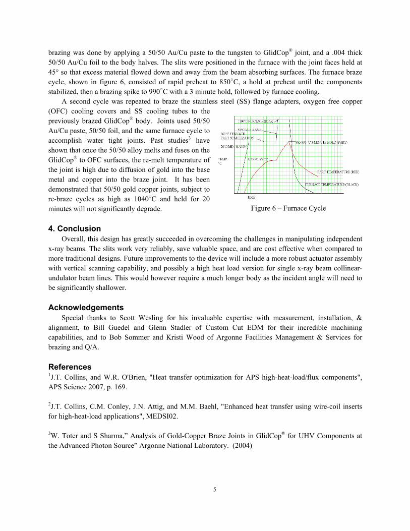
brazing was done by applying a 50/50 Au/Cu paste to the tungsten to GlidCop® joint, and a .004 thick 50/50 Au/Cu foil to the body halves. The slits were positioned in the furnace with the joint faces held at 45° so that excess material flowed down and away from the beam absorbing surfaces. The furnace braze cycle, shown in figure 6, consisted of rapid preheat to 850○C, a hold at preheat until the components stabilized, then a brazing spike to 990○C with a 3 minute hold, followed by furnace cooling.
A second cycle was repeated to braze the stainless steel (SS) flange adapters, oxygen free copper (OFC) cooling covers and SS cooling tubes to the previously brazed GlidCop® body. Joints used 50/50 Au/Cu paste, 50/50 foil, and the same furnace cycle to accomplish water tight joints. Past studies3 have shown that once the 50/50 alloy melts and fuses on the GlidCop® to OFC surfaces, the re-melt temperature of the joint is high due to diffusion of gold into the base metal and copper into the braze joint. It has been demonstrated that 50/50 gold copper joints, subject to re-braze cycles as high as 1040○C and held for 20 minutes will not significantly degrade.
4. Conclusion
Overall, this design has greatly succeeded in overcoming the challenges in manipulating independent x-ray beams. The slits work very reliably, save valuable space, and are cost effective when compared to more traditional designs. Future improvements to the device will include a more robust actuator assembly with vertical scanning capability, and possibly a high heat load version for single x-ray beam collinear- undulator beam lines. This would however require a much longer body as the incident angle will need to be significantly shallower.
Acknowledgements
Special thanks to Scott Wesling for his invaluable expertise with measurement, installation, & alignment, to Bill Guedel and Glenn Stadler of Custom Cut EDM for their incredible machining capabilities, and to Bob Sommer and Kristi Wood of Argonne Facilities Management & Services for brazing and Q/A.
References 1J.T. Collins, and W.R. O'Brien, "Heat transfer optimization for APS high-heat-load/flux components", APS Science 2007, p. 169. 2J.T. Collins, C.M. Conley, J.N. Attig, and M.M. Baehl, "Enhanced heat transfer using wire-coil inserts for high-heat-load applications", MEDSI02. 3W. Toter and S Sharma,” Analysis of Gold-Copper Braze Joints in GlidCop® for UHV Components at the Advanced Photon Source” Argonne National Laboratory. (2004)
Figure 6 – Furnace Cycle