Embed Size (px)
Citation preview

Hindawi Publishing CorporationRehabilitation Research and PracticeVolume 2011, Article ID 590780, 7 pagesdoi:10.1155/2011/590780
Research Article
Validation of a Biofeedback System forWheelchair Propulsion Training
Liyun Guo,1, 2 Andrew M. Kwarciak,1 Russell Rodriguez,1
Nilanjan Sarkar,2 and W. Mark Richter1, 2
1 Biomechanics Laboratory, MAX Mobility, LLC, 5425 Mount View Parkway, Antioch, TN 37013, USA2 Department of Mechanical Engineering, Vanderbilt University, Nashville, TN 37235, USA
Correspondence should be addressed to W. Mark Richter, [email protected]
Received 9 April 2011; Accepted 2 July 2011
Academic Editor: Jeffrey Jutai
Copyright © 2011 Liyun Guo et al. This is an open access article distributed under the Creative Commons Attribution License,which permits unrestricted use, distribution, and reproduction in any medium, provided the original work is properly cited.
This paper describes the design and validation of the OptiPush Biofeedback System, a commercially available, instrumented wheelsystem that records handrim biomechanics and provides stroke-by-stroke biofeedback and targeting for 11 propulsion variables.Testing of the system revealed accurate measurement of wheel angle (0.02% error), wheel speed (0.06% error), and handrim loads.The maximum errors in static force and torque measurements were 3.80% and 2.05%, respectively. Measured forces were alsofound to be highly linear (0.985 < slope < 1.011) and highly correlated to the reference forces (r2 > .998). Dynamic measurementsof planar forces (Fx and Fy) and axle torque also had low error (−0.96 N to 0.83 N for force and 0.10 Nm to 0.14 Nm for torque)and were highly correlated (r > .986) with expected force and torque values. Overall, the OptiPush Biofeedback System providesaccurate measurement of wheel dynamics and handrim biomechanics and may be a useful tool for improving manual wheelchairpropulsion.
1. Introduction
As the study of manual wheelchair propulsion has progressedover the past few decades, so have the tools used to assessand improve propulsion. Early investigations of wheelchairpropulsion focused on physiologic energy costs [1–3] usingcommon medical equipment such as spirometers. In 1976,Brubaker and Ross [4] performed one of the first investiga-tions of wheelchair handrim loading using a custom-madetest stand. The stand included an instrumented beam thatcould measure tangential force applied to the handrim. Otherearly measurements of handrim kinetics involved similar,instrumented fixtures [5, 6]. The continued advancementof wheelchair propulsion research, which included theincorporation of motion capture technology [7] and inertialroller systems [8, 9], led to the development of the self-contained, instrumented wheel [10–13].
Several research groups have developed instrumentedwheel systems that can measure three-dimensional handrimforces and torques [11–13]. Two systems [12, 13] were devel-oped around a commercial, 6 degree-of-freedom load cell.
In both designs, the load cell is mounted to the center ofthe wheel, and an interface plate attaches the handrim tothe load cell. The third system, the SmartWheel, uses anarray of strain gauges, bonded to three beams connecting thehandrim to the wheel, and an optical encoder to measurehandrim kinetics as well as wheel angle and speed [10, 11].Developed by Dr. Rory Cooper and his colleagues at theUniversity of Pittsburgh, the SmartWheel is commerciallyavailable through Three Rivers Holdings, LLC (Mesa, AZ,USA) and has been used by a number of researchers andclinicians to study manual wheelchair propulsion and use[14–17].
While each instrumented wheel system has demonstratedgood accuracy and linearity, as well as the ability to measuretypical propulsion forces and torques, they are limited intheir ability to improve propulsion technique. None of thesystems provide real-time feedback on selectable variablesin an easily interpretable format. The SmartWheel softwarecan display real-time plots of tangential force and speedalong with a set of calculated variables including peak force,push length, and cadence; however, the display cannot isolate

2 Rehabilitation Research and Practice
variables or show performance targets, making it difficultfor users to understand what and how much they shouldimprove. The limitations of instrumented wheels are alsoattributed to their fixed wheel diameters. The SmartWheelis available in multiple sizes, ranging from 22′′ to 26′′,but each size requires the purchase of an additional wheel.Researchers, clinicians, and users can benefit from a moreversatile tool that promotes improvements in wheelchairpropulsion biomechanics.
Expanding upon previous systems, we developed a newinstrumented wheel system, named the OptiPush Biofeed-back System, to measure handrim biomechanics and providereal-time biofeedback for a wide variety of wheelchair users.The system was designed to study propulsion biomechanicsand help train users to improve their propulsion technique.As the OptiPush has gained popularity with cliniciansand researchers, it is important to detail its design andmeasurement accuracy. The purpose of this study was to (1)describe the design of the OptiPush system and (2) validateOptiPush measurements of wheel angle, speed, and three-dimensional handrim forces and torques.
2. Materials and Methods
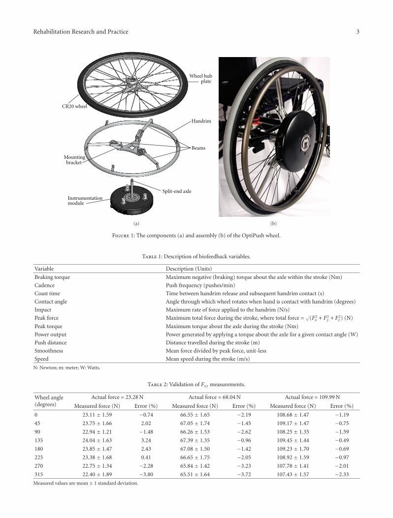
2.1. Mechanical Design. The OptiPush wheel (Figure 1) iscomposed of a Sun CR20 wheel (Sun Components, Milwau-kee, WI, USA), with a modified hub, a handrim, a mountingbracket, three aluminum beams, and an instrumentationmodule (IM). The IM houses the sensors and electrical com-ponents of the device (described in the following section).To measure the loads applied to the handrim, the IM isconnected directly to the handrim through the mountingbracket and beams. The length of beam protruding from thebracket can be adjusted to accommodate different handrimsizes. The outer end of each beam is screwed to one ofthree modified handrim tabs. The IM-handrim assembly ismounted to the wheel by screwing the IM directly to wheelhub plate. This modular instrumentation design allows thesystem to incorporate different sized wheels (20′′, 22′′, 24′′,25′′, and 26′′ diameter). For a 25′′ (559 mm) wheel, the totalmass of the OptiPush wheel is 6.0 kg. Once assembled, thewheel is mounted to the wheelchair by tightening the split-end axle in the axle receiver.
2.2. Electrical Design. The OptiPush wheel measures han-drim loads using a commercially available 6 degree-of-freedom load cell (Delta; ATI Industrial Automation, Apex,NC, USA). The load cell has full-range mechanical load limitof 770 Newtons (N) for forces in the plane of the wheel(Fx and Fy), 2310 N for forces perpendicular to the planeof the wheel (Fz), and 70 Newton-meters (Nm) for torquesabout all three axes. An absolute rotary encoder (MA3; USDigital, Vancouver, WA, USA) is used to measure wheelangle. The encoder reports shaft position continuously over360◦ without gaps. A Bluetooth module (BlueSentry RN-800S; Roving Networks, Inc., Los Gatos, CA, USA), withan 8 channel, 16 bit analog-to-digital converter samples loadcell and encoder signals and converts them to a Bluetooth-enabled digital data stream. The data stream is received
(using a Bluetooth dongle) and recorded by a designatedcomputer running the OptiPush software. All componentswithin the OptiPush wheel are powered by a 7.4 V 2600 mAhLi-ion rechargeable battery, which can provide power formore than three hours before recharging. Two voltageregulators create the required voltage for each component.
2.3. OptiPush Software. The OptiPush Software records,saves, and displays data from the OptiPush wheel. Data aresampled at 200 Hz and filtered with a fourth-order Butter-worth digital low-pass filter with a 20 Hz cutoff frequency[18]. Measurements from a setup trial are used to determinethe dynamic offset of each load cell channel. As data aresampled, the dynamic offsets are removed and the load cellcalibration matrix is applied to the raw voltages, resultingin conditioned force and torque outputs [19]. Data aresegmented into stroke cycles based on absolute torque aboutthe wheel axle (Tz). A stroke cycle begins with the pushphase, the period when Tz exceeds 1 Nm, and ends with therecovery (or coast) phase, the period when Tz is below 1 Nm(Figure 2).
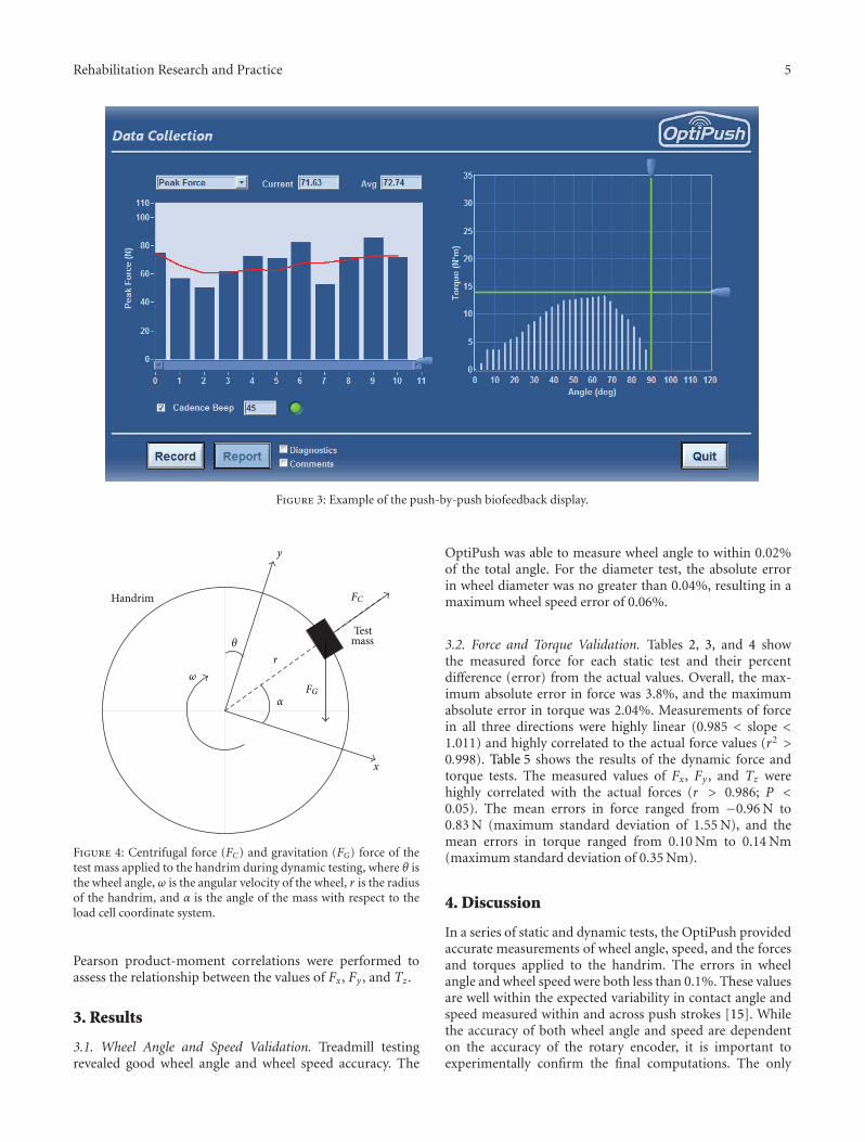
The OptiPush Software includes multivariable biofeed-back, a novel addition to instrumented wheelchair wheeltechnology. Using force, torque, and wheel angle data, thesoftware calculates eleven biofeedback variables: brakingtorque, cadence, coast time, contact angle, impact, peakforce, peak torque, power output, push distance, smooth-ness, and speed (Table 1). Each variable can be displayed in abar graph format (Figure 3) with a running average of the last5 strokes. A target value can be set to help wheelchair usersreach or maintain a desired value. For cadence, an auditorybeep is also available. The efficacy of this biofeedback hasbeen proven in a separate study, in which subjects wereable to use the biofeedback to make significant and targetedimprovements to several propulsion metrics [20].
2.4. System Validation. Static and dynamic tests were con-ducted to validate the ability of the OptiPush BiofeedbackSystem to accurately measure wheel angle, speed, andhandrim forces and torques. For all dynamic tests, theOptiPush wheel was attached to the right side of a QuickieXTR wheelchair (Sunrise Medical, Longmont, CO), andthe wheelchair was attached to a motor-driven, wheelchairaccessible treadmill [21]. The selection of the right sidewas arbitrary. The validity of the system is assumed tobe independent of mounting side. Two safety straps wereattached to the front frame of a wheelchair to prevent it fromveering off the belt or tipping over backwards.
2.5. Wheel Angle Measurement. The treadmill was set torun at a constant speed of about 0.7 m/s. The revolutionsof the wheel (effective diameter: 635 mm) were countedmanually while the OptiPush Software recorded wheel angle.The treadmill was stopped after 100 revolutions had beencounted. Wheel orientations at both the start and stoppositions were measured. The wheel angle measured bythe OptiPush Software was compared with wheel anglecalculated from the wheel revolutions.
Rehabilitation Research and Practice 3
Wheel hubplate
Mountingbracket
Instrumentationmodule
Handrim
Beams
Split-end axle
CR20 wheel
(a) (b)
Figure 1: The components (a) and assembly (b) of the OptiPush wheel.
Table 1: Description of biofeedback variables.
Variable Description (Units)
Braking torque Maximum negative (braking) torque about the axle within the stroke (Nm)
Cadence Push frequency (pushes/min)
Coast time Time between handrim release and subsequent handrim contact (s)
Contact angle Angle through which wheel rotates when hand is contact with handrim (degrees)
Impact Maximum rate of force applied to the handrim (N/s)
Peak force Maximum total force during the stroke, where total force =√
(F2x + F2
y + F2z ) (N)
Peak torque Maximum torque about the axle during the stroke (Nm)
Power output Power generated by applying a torque about the axle for a given contact angle (W)
Push distance Distance travelled during the stroke (m)
Smoothness Mean force divided by peak force, unit-less
Speed Mean speed during the stroke (m/s)
N: Newton; m: meter; W: Watts.
Table 2: Validation of Fxy measurements.
Wheel angle(degrees)
Actual force = 23.28 N Actual force = 68.04 N Actual force = 109.99 N
Measured force (N) Error (%) Measured force (N) Error (%) Measured force (N) Error (%)
0 23.11 ± 1.59 −0.74 66.55 ± 1.65 −2.19 108.68 ± 1.47 −1.19
45 23.75 ± 1.66 2.02 67.05 ± 1.74 −1.45 109.17 ± 1.47 −0.75
90 22.94 ± 1.21 −1.48 66.26 ± 1.53 −2.62 108.25 ± 1.35 −1.59
135 24.04 ± 1.63 3.24 67.39 ± 1.35 −0.96 109.45 ± 1.44 −0.49
180 23.85 ± 1.47 2.43 67.08 ± 1.50 −1.42 109.23 ± 1.70 −0.69
225 23.38 ± 1.68 0.41 66.65 ± 1.75 −2.05 108.92 ± 1.59 −0.97
270 22.75 ± 1.34 −2.28 65.84 ± 1.42 −3.23 107.78 ± 1.41 −2.01
315 22.40 ± 1.89 −3.80 65.51 ± 1.64 −3.72 107.43 ± 1.57 −2.33
Measured values are mean ± 1 standard deviation.

4 Rehabilitation Research and PracticeTo
rqu
eab
out
wh
eela
xle
(Nm
)
10
8
6
4
2
0
0 0.5 1 1.5
Stroke cycle
Push start
Coast phase
Time (s)
phasePush
endPush
Figure 2: Definition of the stroke cycle, push phase, and coastphase.
Table 3: Validation of Fz measurements.
Actual force (N) Measured force (N) Error (%)
23.28 23.31 ± 3.20 0.10
68.04 66.49 ± 3.74 −2.28
109.99 112.66 ± 3.16 2.42
Measured values are mean ± 1 standard deviation.
Table 4: Validation of torque measurements.
VariableActual torque
(Nm)Measured torque
(Nm)Error (%)
√(T2
x + T2y)
6.03 5.99 ± 0.09 −0.56
17.61 17.45 ± 0.10 −0.89
TZ6.03 6.08 ± 0.07 0.87
17.61 17.97 ± 0.07 2.04
Measured values are mean ± 1 standard deviation.
2.6. Speed Calculation. OptiPush wheel speed is calculatedby multiplying angular speed by wheel diameter; therefore,validation required determining the accuracy of both angularspeed (the rate of change of wheel angle) and wheel diameter.Given the previous validation of wheel angle, the accuracy ofthe OptiPush speed calculations were based on the variabilityin experimental calculations of wheel diameter for each ofthe five different OptiPush wheel sizes (508 mm, 559 mm,610 mm, 635 mm, and 660 mm effective diameter). All tireswere inflated to their recommended tire pressure of 758kilopascals (110 psi). To simulate typical conditions, an 85 kgadult male sat in the wheelchair, which was secured to thetreadmill. The treadmill speed was set to approximately 1 m/sand run for 30 seconds. During the trial, the revolutions ofthe treadmill belt and OptiPush wheel were counted. Twotrials were conducted for each wheel size. Using both sets ofrevolutions and the treadmill belt length, wheel diameter (D)was calculated as
D = Revolutions of belt × belt lengthRevolutions of wheel
, (1)
where belt length was 5.69 m. The error in wheel diameterwas then determined as the percent difference between thetwo calculations.
2.7. Force and Torque Measurement. The forces along thefore-aft (Fx) and superior-inferior (Fy) axes and the torqueabout the medial-lateral (Tz) axis were validated with bothstatic and dynamic tests, while the force along the medial-lateral (Fz) axis and the torques about the fore-aft (Tx) andsuperior-inferior (Ty) axes were validated with just statictests. For each test, the forces and torques measured by theOptiPush were compared against the weight, position, andmovement (for dynamic tests) of the attached load.
2.7.1. Static Tests. To test Fx, Fy , and Tz, the OptiPush wheelwas positioned vertically, in the standard wheelchair posi-tion. Three reference loads (23.28 N, 68.04 N, and 109.99 N),similar to those used previously [13], were hung from thebottom of the handrim at eight different wheel angles (0◦–315◦ in 45◦ increments) such that the resultant force in theplane of the wheel (
√[F2
x + F2y]) should equal the weight
of each load. The two smaller reference loads (23.28 N and68.04 N) were also hung on each of the three beams at thepoint of attachment to the handrim (such that the loadradius equaled the handrim radius). Before the load wasapplied, the beam was horizontally leveled so Tz could becalculated as the weight of load multiplied by radius ofhandrim. To test Fz, Tx, and Ty , the OptiPush wheel waspositioned horizontally with the handrim facing upwards.The 23.28 N, 68.04 N, and 109.99 N loads were hung fromeach of the three beams to generate values of Fz. The 23.28 Nand 68.04 N loads were also hung from the handrim such thatthe combined torque (
√[T2
x + T2y]) should equal the weight
of each load multiplied by the radius of the handrim. Eachstatic test lasted about 10 seconds.
2.7.2. Dynamic Tests. Dynamic tests were done to furthervalidate Fx, Fy , and Tz under more realistic testing con-ditions. One at a time, two masses (1.17 kg and 2.30 kg)were secured to the handrim. For each mass, the treadmillwas run at three different speeds (0.5 m/s, 1.0 m/s, and1.5 m/s) for at least 10 wheel revolutions. As the wheelrotated on the treadmill belt, the attached mass applied adownward (gravitational) and outward (centrifugal) force tothe handrim (Figure 4). The centrifugal forces in the plane ofthe wheel (Fx and Fy) and torque about the wheel axle (Tz)were calculated with the following equations:
Fx = FG · sin(θ) + m · ω2 · r · cos(α),
Fy = −FG · cos(θ) + m · ω2 · r · sin(α),
Tz = FG · cos(α− θ) · r,
(2)
where θ is the wheel angle; ω is the angular velocity of thewheel; r is the radius of the handrim; m is the added mass,and α is the angle of the mass. Since the values of Fx andFy could be zero during testing, the errors were presented asthe differences between the measured and calculated values.
Rehabilitation Research and Practice 5
Figure 3: Example of the push-by-push biofeedback display.
x
y
FG
FCHandrim
Testmass
α
θ
ω
r
Figure 4: Centrifugal force (FC) and gravitation (FG) force of thetest mass applied to the handrim during dynamic testing, where θ isthe wheel angle, ω is the angular velocity of the wheel, r is the radiusof the handrim, and α is the angle of the mass with respect to theload cell coordinate system.
Pearson product-moment correlations were performed toassess the relationship between the values of Fx, Fy , and Tz.
3. Results
3.1. Wheel Angle and Speed Validation. Treadmill testingrevealed good wheel angle and wheel speed accuracy. The
OptiPush was able to measure wheel angle to within 0.02%of the total angle. For the diameter test, the absolute errorin wheel diameter was no greater than 0.04%, resulting in amaximum wheel speed error of 0.06%.
3.2. Force and Torque Validation. Tables 2, 3, and 4 showthe measured force for each static test and their percentdifference (error) from the actual values. Overall, the max-imum absolute error in force was 3.8%, and the maximumabsolute error in torque was 2.04%. Measurements of forcein all three directions were highly linear (0.985 < slope <1.011) and highly correlated to the actual force values (r2 >0.998). Table 5 shows the results of the dynamic force andtorque tests. The measured values of Fx, Fy , and Tz werehighly correlated with the actual forces (r > 0.986; P <0.05). The mean errors in force ranged from −0.96 N to0.83 N (maximum standard deviation of 1.55 N), and themean errors in torque ranged from 0.10 Nm to 0.14 Nm(maximum standard deviation of 0.35 Nm).
4. Discussion
In a series of static and dynamic tests, the OptiPush providedaccurate measurements of wheel angle, speed, and the forcesand torques applied to the handrim. The errors in wheelangle and wheel speed were both less than 0.1%. These valuesare well within the expected variability in contact angle andspeed measured within and across push strokes [15]. Whilethe accuracy of both wheel angle and speed are dependenton the accuracy of the rotary encoder, it is important toexperimentally confirm the final computations. The only

6 Rehabilitation Research and Practice
Table 5: Results of dynamic testing.
Test Mass = 1.17 kg Test Mass = 2.30 kg
Variable Speed (m/s) Correlation coefficientMeasured
value-actual valueCorrelation coefficient
Measuredvalue-actual value
Fx (N)0.5 0.989 −0.04 ± 1.20 0.998 0.11 ± 1.31
1.0 0.994 0.31 ± 0.93 0.998 0.83 ± 1.22
1.5 0.994 0.42 ± 0.92 0.997 0.69 ± 1.36
Fy (N)0.5 0.988 −0.20 ± 1.32 0.997 −0.28 ± 1.25
1.0 0.993 −0.60 ± 1.03 0.998 −0.96 ± 1.03
1.5 0.993 −0.81 ± 1.16 0.995 −0.60 ± 1.55
Tz (Nm)0.5 0.999 0.13 ± 0.08 0.999 0.14 ± 0.11
1.0 0.997 0.13 ± 0.17 0.998 0.14 ± 0.26
1.5 0.986 0.11 ± 0.35 0.998 0.10 ± 0.25
Differences in the values are mean ± 1 standard deviation.
other instrumented wheel to include a rotary encoder is theSmartWheel, for which wheel angle and speed measurementaccuracies are unavailable.
For force and torque measurements, the maximum errorswere 3.8% and 2.04%, respectively. These errors are withinthe factory-determined error of the load cell (1.5% of thefull-scale load limit of each axis) and comparable to thoseof other instrumented wheels [11, 13]. The fact that forceerror was larger than torque error was expected, as the full-range load limits for force measurement (770 N for Fx andFy ; 2310 N for Fz) are larger than the load limit for torquemeasurement (70 Nm). The linearity was also high andconsistent with previous systems [11–13]. In dynamic tests,the measurements of Fx, Fy , and Tz were all highly correlatedwith the calculated values. The errors in each measure weresmall and may be attributed to treadmill vibrations and/orinaccuracies in calculating the effect of the reference masses.Due to difficulties in measuring the weight center of themass attached to the handrim, there may have been errorsin the relative angles of mass. While these errors could haveaffected the accuracy in calculating the reference force andtorque values, they were not large enough to warrant furtherinvestigation.
5. Conclusions
The modular design of the OptiPush wheel and the accuracywith which it can measure wheel angle, speed, and handrimforces and torques make the OptiPush Biofeedback Systeman effective tool for assessing handrim biomechanics. Futureinvestigations will test the effects of multivariable biofeed-back and develop training protocols to improve propulsionbiomechanics.
References
[1] G. A. Wolfe, R. Waters, and H. J. Hislop, “Influence of floorsurface on the energy cost of wheelchair propulsion,” PhysicalTherapy, vol. 57, no. 9, pp. 1022–1027, 1977.
[2] G. Hildebrandt, E. D. Voigt, D. Bahn, B. Berendes, and J.Kroger, “Energy cost of propelling a wheelchair at variousspeeds: cardiac response and the affect of steering accuracy,”
Archives of Physical Medicine and Rehabilitation, vol. 51, no. 3,pp. 131–136, 1970.
[3] R. M. Glaser, M. N. Sawka, L. L. Laubach, and A. G.Suryaprasad, “Metabolic and cardiopulmonary responses towheelchair and bicycle ergometry,” Journal of Applied Physi-ology Respiratory Environmental and Exercise Physiology, vol.46, no. 6, pp. 1066–1070, 1979.
[4] C. E. Brubaker and S. Ross, “Static and dynamic com-parisons of selected handrims for wheelchair propulsion,”in Wheelchair Mobility 1976–1981, W. Stamp and C. A.McLaurin, Eds., pp. 28–31, Rehabilitation Engineering Center,University of Virginia, 1976.
[5] L. H. V. van der Woude, H. E. J. Veeger, and R. H. Rozendal,“Propulsion technique in hand rim wheelchair ambulation,”Journal of Medical Engineering and Technology, vol. 13, no. 1-2, pp. 136–141, 1989.
[6] K. Samuelsson, H. Larsson, and H. Tropp, “A wheelchairergometer with a device for isokinetic torque measurement,”Scandinavian Journal of Rehabilitation Medicine, vol. 21, no. 4,pp. 205–208, 1989.
[7] D. J. Sanderson and H. J. Sommer, “Kinematic features ofwheelchair propulsion,” Journal of Biomechanics, vol. 18, no.6, pp. 423–429, 1985.
[8] R. Niesing, F. Eijskoot, R. Kranse et al., “Computer-controlledwheelchair ergometer,” Medical and Biological Engineering andComputing, vol. 28, no. 4, pp. 329–338, 1990.
[9] L. C. Masse, M. Lamontagne, and M. D. O’Riain, “Biome-chanical analysis of wheelchair propulsion for various seatingpositions,” Journal of Rehabilitation Research and Development,vol. 29, no. 3, pp. 12–28, 1992.
[10] R. A. Cooper, K. T. Asato, R. N. Robertson, and J. F. Ster, “2-dimensional kinetic analysis of manual wheelchair propulsionwith an improved SMARTwheel,” in Proceedings of the 14thAnnual International Conference of the IEEE Engineering inMedicine and Biology Society (EMBS ’92), pp. 1544–1545,Paris, France, October-November 1992.
[11] K. T. Asato, R. A. Cooper, R. N. Robertson, and J. F.Ster, “SMARTwheels: development and testing of a system formeasuring manual wheelchair propulsion dynamics,” IEEETransactions on Biomedical Engineering, vol. 40, no. 12, pp.1320–1324, 1993.
[12] H. W. Wu, L. J. Berglund, F. C. Su et al., “An instrumentedwheel for kinetic analysis of wheelchair propulsion,” Journal ofBiomechanical Engineering, vol. 120, no. 4, pp. 533–535, 1998.

Rehabilitation Research and Practice 7
[13] W. Limroongreungrat, Y. T. Wang, L. S. Chang, M. D. Geil, andJ. T. Johnson, “An instrumented wheel system for measuring3-D pushrim kinetics during racing wheelchair propulsion,”Research in Sports Medicine, vol. 17, no. 3, pp. 182–194, 2009.
[14] W. J. Hurd, M. M. B. Morrow, K. R. Kaufman, and K. N. An,“Wheelchair propulsion demands during outdoor communityambulation,” Journal of Electromyography and Kinesiology, vol.19, no. 5, pp. 942–947, 2009.
[15] R. E. Cowan, M. L. Boninger, B. J. Sawatzky, B. D. Mazoyer,and R. A. Cooper, “Preliminary outcomes of the SmartWheelUsers’ Group database: a proposed framework for clinicians toobjectively evaluate manual wheelchair propulsion,” Archivesof Physical Medicine and Rehabilitation, vol. 89, no. 2, pp. 260–268, 2008.
[16] A. M. Kwarciak, S. A. Sisto, M. Yarossi, R. Price, E. Komaroff,and M. L. Boninger, “Redefining the manual wheelchair strokecycle: identification and impact of nonpropulsive pushrimcontact,” Archives of Physical Medicine and Rehabilitation, vol.90, no. 1, pp. 20–26, 2009.
[17] A. Gil-Agudo, A. Del Ama-Espinosa, E. Perez-Rizo, S. Perez-Nombela, and B. Crespo-Ruiz, “Shoulder joint kinetics duringwheelchair propulsion on a treadmill at two different speedsin spinal cord injury patients,” Spinal Cord, vol. 48, no. 4, pp.290–296, 2010.
[18] C. P. DiGiovine, R. A. Cooper, R. N. Robertson, M. L.Boninger, and S. D. Shimada, “Frequency domain analysis ofwheelchair pushrim forces and moments,” in Proceedings of theRehabilitation Engineering and Assistive Technology Society ofNorth America Annual Conference (RESNA ’96), pp. 238–240,Salt Lake City, Utah, USA, 1996.
[19] K. R. Woods, W. M. Richter, R. Rodriguez, and P. W. Axelson,“Removal of dynamic offset signal from load cell instrumentedwheels,” in Proceedings of the 27th International Conference onRehabilitation Engineering and Assistive Technology Society ofNorth America (RESNA ’04), Orlando, Fla, USA, June 2004,(CD-ROM).
[20] W. M. Richter, A. M. Kwarciak, L. Guo, and J. T. Turner,“Effects of single-variable biofeedback on wheelchair handrimbiomechanics,” Archives of Physical Medicine and Rehabilita-tion, vol. 92, no. 4, pp. 572–577, 2011.
[21] A. M. Kwarciak, J. T. Turner, L. Guo, and W. M. Richter, “Com-paring handrim biomechanics for treadmill and overgroundwheelchair propulsion,” Spinal Cord, vol. 49, no. 3, pp. 457–462, 2010.

Submit your manuscripts athttp://www.hindawi.com
Stem CellsInternational
Hindawi Publishing Corporationhttp://www.hindawi.com Volume 2014
Hindawi Publishing Corporationhttp://www.hindawi.com Volume 2014
MEDIATORSINFLAMMATION
of
Hindawi Publishing Corporationhttp://www.hindawi.com Volume 2014
Behavioural Neurology
EndocrinologyInternational Journal of
Hindawi Publishing Corporationhttp://www.hindawi.com Volume 2014
Hindawi Publishing Corporationhttp://www.hindawi.com Volume 2014
Disease Markers
Hindawi Publishing Corporationhttp://www.hindawi.com Volume 2014
BioMed Research International
OncologyJournal of
Hindawi Publishing Corporationhttp://www.hindawi.com Volume 2014
Hindawi Publishing Corporationhttp://www.hindawi.com Volume 2014
Oxidative Medicine and Cellular Longevity
Hindawi Publishing Corporationhttp://www.hindawi.com Volume 2014
PPAR Research
The Scientific World JournalHindawi Publishing Corporation http://www.hindawi.com Volume 2014
Immunology ResearchHindawi Publishing Corporationhttp://www.hindawi.com Volume 2014
Journal of
ObesityJournal of
Hindawi Publishing Corporationhttp://www.hindawi.com Volume 2014
Hindawi Publishing Corporationhttp://www.hindawi.com Volume 2014
Computational and Mathematical Methods in Medicine
OphthalmologyJournal of
Hindawi Publishing Corporationhttp://www.hindawi.com Volume 2014
Diabetes ResearchJournal of
Hindawi Publishing Corporationhttp://www.hindawi.com Volume 2014
Hindawi Publishing Corporationhttp://www.hindawi.com Volume 2014
Research and TreatmentAIDS
Hindawi Publishing Corporationhttp://www.hindawi.com Volume 2014
Gastroenterology Research and Practice
Hindawi Publishing Corporationhttp://www.hindawi.com Volume 2014
Parkinson’s Disease
Evidence-Based Complementary and Alternative Medicine
Volume 2014Hindawi Publishing Corporationhttp://www.hindawi.com


![[3.5 Monster Class] Roving Mauler](https://img.pdfslide.us/doc/110x75/55cf9a9d550346d033a2973a/35-monster-class-roving-mauler.jpg)