Embed Size (px)
Citation preview
--
-""--"""
, ... 2 . (
INDEXING DATA
J
LS006-002-2H
APRIL 19,1971
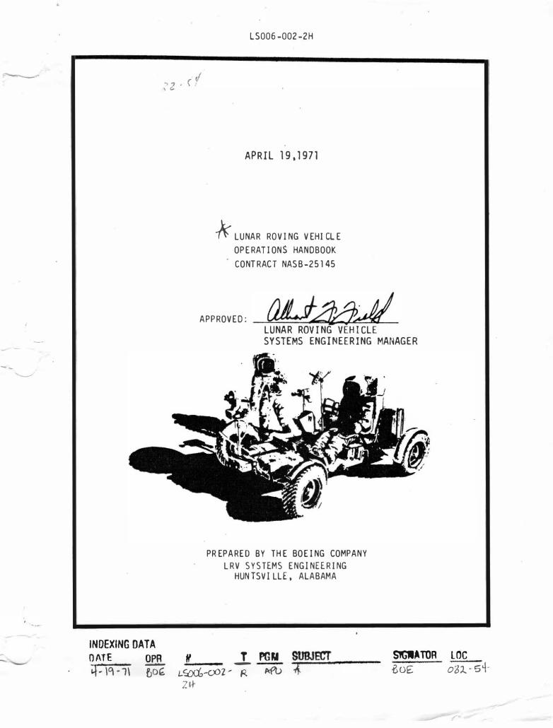
k LUNAR ROVING VEHICLE OPERATION$ HANDBOOK CONTRACT NASB-25145
APPROVED: a;UA5.J/ LUNAR ROVING VEHICLE SYSTEMS ENGINEERING MANAGER
PREPARED BY THE BOEING COMPANY LRV SYSTEMS ENG INE ERING
HUNTSVILLE, ALABAMA
OA lE OPR #f T PGM SUBJECT 4� 1q -1\ � 1-m-cxn ... -; P<fl> .;;,1{:;.;;.;;.;:;.;;.;..---
S?QIATOR LOC -BoE oZ:l.. -5+
ZH·
LS0 0 6-0 0 2-2H LUNAR ROVING VEHICLE
OPERATIONS HANDBOOK
Reproduction for non-�overnment use of the information or illustrations contained in th•� puld •cation '' n'lt perm1tted without specific approval of the issuing service.
LIST OF EFFECTIVE PAGES INSERT L�TEST CHANGED PAut�
DESTROY SUPERSEDED PAGES.
TOT/IL NUI�BER OF PAGES IN TilTS PU13LICATION IS 342, CONSISTING OF THE FOLLOWINr:
PAGE IW.
Title A
i thru viii 1--1 thru 1-78 2-1 thru 2-50 3-1 th�u 3-12 4-1 thru 4-11 5-l tht'U 5-4 601 t.hru 6-18 7-1 t.hru 7-6 8-1 thru 8-31
Tit1e (Ar-pendix A' A-i tl11·u A-v A-·1 thru A-105
Title (ArpE!n�i x B) B-i B- ii 13-1 t.hru 13-8
TSSUF
19 April 1971 19 ,ol.pri) 1971
19 Apri 1 1971 19 April 1971 19 April 1971 19 April 1971 19 April 1971 19 April 1971 19 April 1971 19 April 1971 19 April 1971
19 April 1 �71 19 April 1971 19 April 1971
15 January 1 �71 15 Jal"u,,ry 1971 15 Jcmua r.v 1971 15 January 1971
Mission J Basic Dat e 12/4{_70 Change Date 4/19/71 Pa9e
� t . ... f. . .
, · ·.\ ; ... ; • :! 1 : .. ! . ... ... -· . . .. , . .
"'�:·) 1
. . . . . " . .
.. -:
• I, �' '
A
LS006-002- 2H LUNAR ROVING VEHICLE
OPERATIONS HANDBOOK
HANDBOOK CONFIGURATION
This handbook reflects the Lunar Roving Vehicle (LRV) and Space Support Equipn�nt (SSE) delivery review configuration as modified by incorporation of the following:
ECP DESCRIPTION
LRV 1097 Incorporation of Manual SSE
LRV 1073 Seat Belt Modification
LRV 10 75 Rear Steering Recoupling
LRV 1104 Thermal Blanket
LRV 1103 Switch Guards
f-li ss ion Basic Date 12/4/70 Change Date 41191 71 Page ----
--- -
.-/
Sl:CTION
1.0 1.1 1.2 1.3 1.4
1.5 1.6 1. 7 1. 8 1.9
,, '
2. 1 Z.2
2.3 2.4 2.5 2. 6 2. 7 2.8
3
3.0
4
4.0 4. 1 4.2
4.3
s
5. 1 S.2
5.3 5.4
LS006-002-2 H LUNAR ROVING VEHICLE
OPERATIONS HANDBOOK
TABLE OF CONTENTS
TITLE
Genera 1 Information
Introduction De�.cri ption Vehicle Systems Mobility Subsystem ElE·ctri cal Power Subsys tern Contt·o 1 and Display Console Navig ation Subsystem Crew Station Thermal Control Space Support Equipment
Normal Procedures
Unloading and Cha�sis Deployment Post Deployment Checkout and Drive Pt1yload Loading Pre-Sortie Checkout and Preparation LRV Configuration for Science Stop
to I•;ESA
LRV Configuration Prior to Leaving Science Post �ortie Checkout Display Reading Sequence and Time Intervals
Malfunction Procedures
Introduction
Auxiliary Equipment
Introduction Forward Chassis Payload Provisions C�nter Chassis Payload Provisions Rear Chassis Payload Provisions
O�eratin� Limitations
Payload Limitations I'" ark i ng Limit at i l'ns Sortie Limitations Navigation Sy5tem Limitations
P/�GE
1 -1
1 -1 1 -1
1 -1 i -5
1-28 1-3 7 1-42 l-4S
1-54 1-64
2-1
2 -2 2-22 2-29 2-41 2-45
Stop 2-4& 2-4 8 2-50
3-1
3-1
4-1
4-1 4-1 4-1 4-6
5-l
5-1 5-1 5- l 5-4
---M
-i s_s_
i_o
_n---------
.--
B-as
_i_
c __
D-at-e
-- --12_/_4_
/_7_0 __
C_ h_ a_
n_ge __ D_ a_t
_e--�4/�1�9�/� 7�1 -- �Pa_
g_ e __ ii ----

-----
SECTION
6
7
t
6. 0
7. 1 7. 2
8. 0 8. 1 8.2 8. 3
LS006-002-2H LUNAR ROVING VEHICLE
OPERATIONS HANDBOOK
ThBLE OF CONTENTS (Continued)
TITLE
Operating Timelines
Introduction
Opera ting Profiles
LRV Operating Profile lG Tra iner Operating Profile
lG Trainer Non-Crew rrocedur�s
Introduction G eneral Procedures Specific Procedures Preventive Maintena nce Assembly Remove and
Replace Procedures
--------------·--------------Missi on 12/4/70 Change Dat e -�/_! 9j_7_! __ Pa11e Basic Dat e
------·
P1�G E
6-1
6-1
7-1
7-1 7-4
8-1
8-1 8-1 8-1 £ 8-28
i i i
--
FIGURE NO.
1 -1 1-2 1 -3 "1-4 1 -5 1 - 6 1 -7 1-8 1-9 1 -1 0 1 -1 1 1 -12
1 -1 3
1 -1 4 1 -1 5 1 -1 6 1 . 1 7 1 . 1 8 1 -1 9 1 -20 1 -21 1 . 22 1 -23 1 -2� 1 -25 1 -26 1-27 1 -28 1-29 1-30 1 -31 1 -32 1 -33 1 -34 1 -35 1 -36 1 -3/ 1 -38 1-39 1-4 0 1 -41 1 -4 2
LS006-002-2H LUNAR ROVING VEHICLE
OPERATIONS HANDBOOK
LIST OF ILLUSTRATIONS
Lunar Ro ving Vehicle lG Tr ainer Mob ility Sub system
TITLE
LRV Wheel Cro ss-Sectio n LRV Tractio n Drive Assembly lractio n Drive Installatio n 5usp ensio n Assembly Steering Assembly Steering Co ntro l Blo ck Diagram �:eel and Steering Disco nnects Hand Co ntro ller
To rque Required to Ro tate Hand Co ntro ll er fo r Thro ttle Co ntro l
To n1ue Required to Ro tate Hand Co ntro ller fo r Steering Co ntro l
Br�ke Co ntrol Fo rce Vs. Displacement Drive Co ntro l Electro nics - Blo ck Dia9ram LRV Battery Co nfiguratio n LIW Batteries, Thermal Blanket and Dust Co vers Power Distr·ibutio n System Schematic lllV Mo nito r Schematic Cautio n and Warning System Aux iliary Co nnecto r Lo catio n Co ntro l and Display Co nso le Navigatio n Subsystem Blo ck Diagram Navigatio n Co mpo nents o n LRV Naviga tio n System E lectrical Schematic Vehicle Attitude Indicato r Sun Shndo w Device Crew Statio n Co mpo nents s�at Bel ts Crew Statio n Floo r Panels
Thermal Co ntro l Pro visio ns Drive Co ntro ller El�ctro nics Thermal Co ntro l SPU E lectro nics and Battery #1 Thermal Co ntro l Battery #2 and Directio nal Gyro Unit Thermal Co ntro l Battery Dust Co ver Clo sing Mechanism Fo rward Chassis Insulatio n Blanket Space Suppo rt Equ�pment
LM/SSE "with LRV Installed LRV Deplo yment Sequence lnsulatio 11 Blanket LRV Depl o yment Tapes and Cables ll-liundle Rel ease System
Mission __ J __ _ Basic lJa te 1 2/4/70 Change Date 4/1 9/71 Pa�e
PAGE
1 . 2 1 -4 1 -6 1-7 1 -9 1-1 1 1 -1 4 1 -1 6 1 -1 7 1 -1 8 1 -19 1 -21
1 -22
1 -24 i -26 1 -29 1 -30 1 -32 1-33 1 -34 1-36 1-38 1 -4 3 1 -4 4 1 -4 S 1 -4 6 1 ..:4 7 1 -50 1 -52 1-53 1 -55 1 -56 1 -5/ 1 -58 1-59 1-6ll 1-66 1 -G 7 1 -68 1 -69 1 -70 1 -71
i v
---
FIG URE NO.
1-� 3 1 -4 '1 l-4 S 1 -4 6 l -4 7 2-1 2-2 2-3
2-4 2-5 2-6
':'.-7 2-8 2-9 2-10 2-11 2--1 2 2-13 2-1 4 2--15
2-1 6 2-1 7 2-1 8 4 -1 4 -2 4 -3
4 -4 <l-5 lj -6
4 -7 li-8 4 -9 5-1 5-2 6-1 6-2
6-3 (·-'1 (i -5 6-6
LS006-002-2H LUNAR ROVING VEHICLE
OPERATIONS HANDBOOK
LIST OF ILLUSTRATIONS (CONTINUED)
TITLE
LRV/SSE Support Structure and Releilse Syslen1 Braked Reel LRV Saddle and Forward Chassis Latch Sysi.em Forward and Rear Chassis Latch Wheel Lock Strut Release Support Ann Latch Mechanisms Latched Configuration LRV Deployment Tapes and Cables LllV Deployment Envelope and Envelope for Deployment Tape Operations
Crewman Positioned to �eploy LRV LRV Deolnvment Sequence LRV Deployment Hardware & Steer�ng Ring Location Foot Rest Dep 1 oyment Control and Display Console Deployment Seat and PLSS Support Deployment Sequence Crew Position Control an� Display Console LCRU/TV/LRV Cable Stowage
LCRU, HighG ain Antenna, TV Camera Installation 16 rm1 DAC and Low G ain Antenna Install ation LCRU Low G ain Antenna Cable Installation on Lunar
Surface LRV Rear Payload Pallet Adapters Rear Payload Pallet Installed Buddy SLSS Installation LCRU, High G ain Antenna, TV Camera Installation LCRU/TV/LRV Cable Stowage LCRU Low G ain Antenna Cable Installation on Lunar
Surface lf, mr.� DAC and Low G ain Antenna Installation Under-s�at Stowage Gag (Left �eat) Pnssenger Seat Stowage to Create Pnyload Arfa on
Center Chassis Floor Buddy SLSS Irstallation LRV Rear laylcad Pallet Adapters Re ar Payload Pallet Installed All0wable C.G . E nvelope for Vehicl e Fully Loaded Pdrking Orientation Constraints LRV Deployn�nt Timeline f'ost [ieployment Checkout Timeline Prr.-�or.�ie Checknut and Pre>paration Timelinc; Post SortiE Shutdown Timelinc
Navigation Update Tin�line LllV Traction Drive Decoupl ing Timel inc
Mission J Basic Date 12/4/70 Change Date 4/19 /71 ---�
Page
PJ\GE
1-72 1-73 1 -7�. 1 -76 1 -77 �-3 2-4 2-6
2-7 2-·9 2-1 1 2-1 5 2-16 2-1 7 2-24 2-2t"· 2-30 2-31 2-34 2-36
2-37 2-39 2-4 0 4 -2 4 -3 4 -4
4 -5 4 -7 4 -8
4 -9 4 -1 0 4 -1 1 5-2 5-� 6-2 6-7
6-9 6-11 f.-12 6-1 2
v
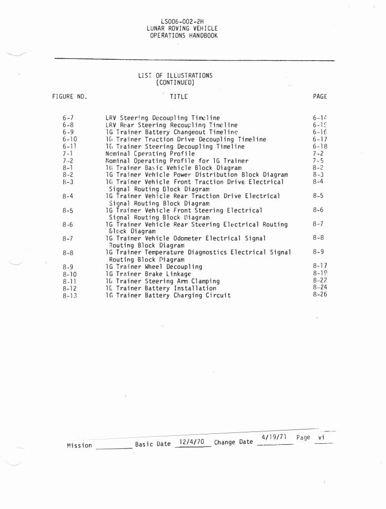
FIG URE NO.
6-7 6-8 6-9 6-10 6-11 7-1 7·-2 8-1 8-2 H-3
8-4
8-5
8-6
8-7
8-8
8-9 8-10 8-11 8-12 8-13
LS006-002-2H LUNAR ROVING VEHICLE
OPERATIONS HANDBOOK
LIST OF ILLUSTRATIONS.
( CONTINUED) TITLE
LRV Steering De coupling Timeline LRV Rear Steering Recou�linn Tinx:line lG Trainer Battery Changeout Timelinc 1(, Trainer Traction Drive Decoupling Timeline H, Tr·ainer Steering Decoupling Timeline Nominal Operating Profile Nominal Operating Profile for lG Trainer lli Trainer Basic Vehicle Block Diagram lG Trainer Vehicle Power Distribution Block Diagram Hi Trainer Vehicle Front Traction Drive Electrical
Signal Routing Olock Diagram lG Trainer Vehicle Rear Traction Drive Electrical Signal Routing Block Diagram
lG Trainer Vehicle Front Steering Electrical SiQnal Routing Block Diagram
lG Trainer Vehicle Rear Steering El�ctrical Routing &lock Diagram
lG Trainer Vehicle Odometer Electrical Signal Routing Block Diagram
lG Trainer Temperature Diagnostics Electrical Signal Routing Block Oiagram
lG Trainer Wheel Decoupling lG Trainer Brake Linkage lG Trainer Steering Arm Clamping lG Trainer Battery Installation lG Trainer Battery Charging Circuit
PAG E
6-ll. 6-E 6-1 f, 6-17 6-18 7-2 7-5 8-2 8·-3 8-4
8-5
8-6
8-7
8-8
8-9
8-17 8-19 8-2?. 8··24 8-26
------------------------------------------�4�/1�9�/�7l��P�a-ge�vi Mission Basic Date 12/4/70 Change Date -----�
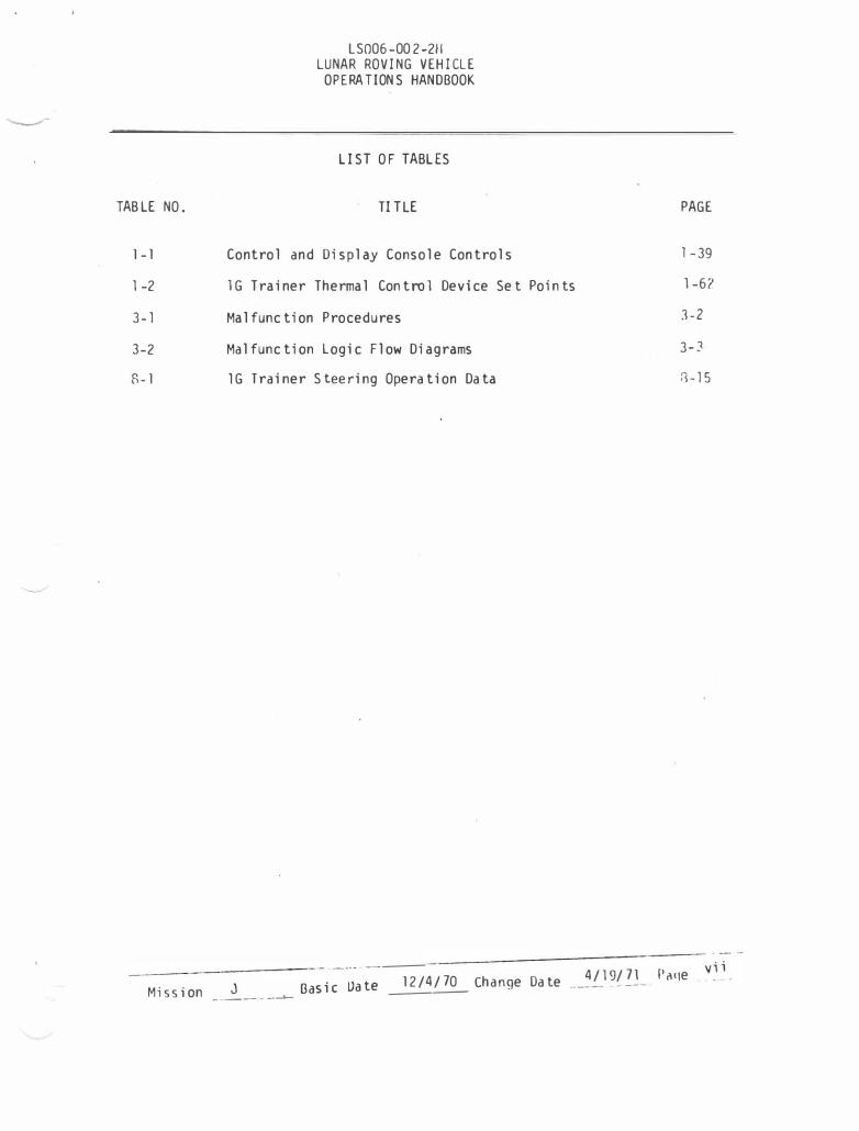
TABLE NO.
1 -1
1 -2
3-1
3-2
R -1
LS006-002-211 LUNAR ROVING VEHICLE
OPE RATIONS HANDBOOK
LIST OF TABLES
TITLE
Control and Display Console Controls
l G Trainer Thermal Control Device Set Point s
Malfunction Procedures
Malfunction Logic Flow Diagrams
lG Trainer Steering Operation Data
-------- ---- ---12/4 /70 Change Dat e 4 /19/71
Mission ---J Basic Oat e ------�
-·---- - -·-
PAG E
l-39
1-62
3-2
3-J
8-15
Paqe " ; ;
LS006-002-2H LUNAR ROVING VEHICLE
OPERATIONS HANDBOOK
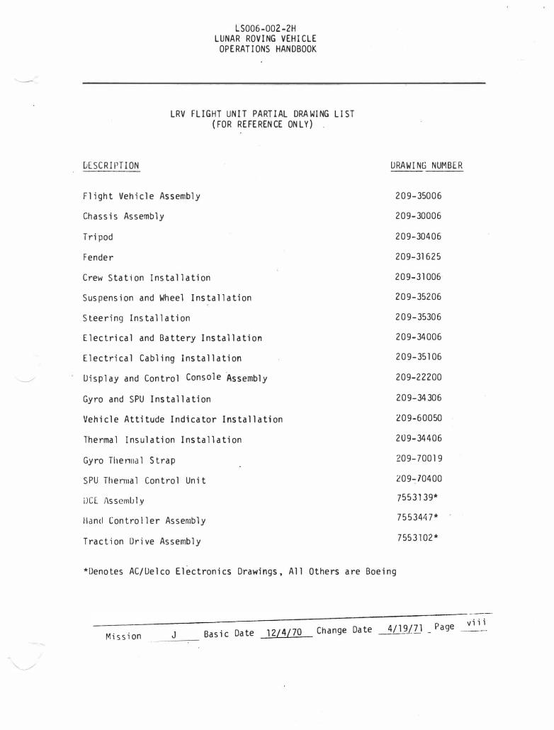
LRV FLIGHT UNIT PARTIAL DRAWING LIST (F OR REFERENCE ONLY )
uESC RIPTI ON
Flight Vehicle Assembly
Chassis Assembly
Tripod
Fender
Crew Station Installation
Suspension and Wheel Installation
Steering Installation
Electrical and Battery Installation
Electrical Cabling Installation
Display and Control Console �ssembly
Gyro and SPU Installation
Vehicle Attitude Indicator Installation
Thermal Insulation Installation
Gyro Tllennal Strap
SPU Thenna l Control Unit
IJCE /\s s cmlJ l y
Hand Controller Assembly
Traction Drive Assembly
DRAWING NUMBER
209-35006
209-30006
209-30406
209-31625
209-3 1006
209-35206
209-35306
209-34006
209-35 106
209-22200
209-34306
209-60050
209-34406
209-70019
209-)0400
75 5 3 139*
75 5 3 4tl7*
755 3 102*
*Denotes AC/Delco Electronics Drawings, All Others are Boeing
----------------
----- ---------------------------��--:-----
,vi i i Change Date 4/l9LZJ _ Page
Mission J Basic Date 12/4/70 ------c--
._
1.0 INTRODUCTION
LS006-002-2H LUNAR ROVING VEHICLE
OPERATIONS HANDBOOK
SECTION I
GENERAL INFORMAT ION
This section contains general information pertaining to the flight operational Lunar Roving Vehicle (LRV). Where applicable, the lG Trainer differences are noted.
1.1 DESCRIPTION
The LRV system on the lunar surface consists of the LRV, the structure for securing the LRV to the LM stowage bay and the mechanism for deploying the LRV from the LM onto the lunar surface.
1 . 2 VEHICLE SYSTEMS
The LRV (figure 1-1) is a four-wheeled, self-propelled, manually controlled vehicle to be used for transporting crewmen and equipment on the lunar surface. The vehicle has accommodations for two crewmen and the stowed auxiliary equipment designed for the particular mission.
Control of the LRV during traverses is effected from either of the two crewmen positions by operating the hand controller located between the two crewmen positions. Selection of power supplied to each load, monitoring of key parameters, and operation of the navigation system is effected from the control and display console, which is located for operation by either crewman.
***lG Trainer Notes***
1. lG Trainer vehicle systems are shown on figure 1-2.
2. Electrical block diagrams for the lG Trainer are provided in Section 8.0.
----------------- ----
12/4/ 70 Change Uate -�_!_9!__?..!..__ Paqe Miss ion J Basic Date
-----·- -
1-1
0
0
CD 0 0 0
� ll\�WI\1(11 ll!o I' 'I hit M l 111"\'.·,t All LIIA>>I�
\, 'I'IH\ION S!SIIH
A \II'I'IN�IO� AltM\ (UPrtW ANIJ IOWik) ... ION<IOII �AN', (lll'rlN �HI• lUWlR) L. Uo\HPLR
�lllNII«o \1\l.� (lilNWARU ANU Ml) :R.\\111·\ IINIYL
.:!J..!...L . M i ll d lH I NUL
•·1\NU lU'tlkUlll" ,,NfJl lO,tlr«ll IU .. :I,I'th\ lUll)
LS006-002-2H LUNAR ROVING VEHICLE
OPERATIONS HANDBOOK
Q)
®
G
lMLW �IAIIOII
�. I l. u. l. f. c. "
l.�lAOl AHU 01\111 A'f lllh\ttll \LAT IOOUlH OUTBOAID HAIIOHOI.U IIIIQMD HMGIIOI.D flllllU 10(11"-SUI l
POIIlR S!) I U1
A. OAIJ[R! •I B. nAIJLRT •l c. l NSTR�[IIlA I I (lfl
'IIAYILAI(UN
A . UloLLIIOioAl GYA" •· .( 1 (t>(;t•l
L )I&IIAL PWOllHir.t. ... , , . ,., , L. llollGWAillt I'O)(IIUI• ll•t I";.,� (II' I) o. S� � UlVILI l. Vlillll A1lll••l lhl.lh··ill'-
@ lltlk,.,_L I.UNI"UI
ll'f',IILAIItiJt l:l:,r,, t I u. HAll I kl IIU. I UIJ',, '''VII. L. I.AIIl NT ltU. , : .. r 1 •• • •, u. ' .I'll UU\ I CUVI " I. ull IHLPfi!AL. lU!tlklll .... ,, I hAlHN'r Jftl I NlouiMiv• L. I:Aill'Y NU, I .1.01/.lll� II, \I'U lt•l ... Jt.ll l11hd11Jl !;".)I
@ PA!LOAU HHI Rf ACL
A. IV lAIUNA NlllPIAILL c. LCRU RlliPI�lll l. IIIGt1 t,AIU AUHitUfl �tllllr.,,, "- AUJ ILIUT CUNNI\ 1'1 I. LOW C.Afl, JJULW.t• .. 1, ,, I C. 1
FIGURE 1-1 LRV WITHOUT STOWED PAYLOAD (SHEET 1 OF 2)
Mission ____ Basic Date 12/4/70 Change Date �9/71 __ f'arJ� 1-2
::s: v> Vl
0 ::I
c....
OJ 01 v>
n 0 01 ,.... (I)
N ........ � ........ -...J 0
n :::T 01 ::I
10 (I)
0 01 ,.... (I)
� ........
I� ,�
"'0 01
10 (I)
I:: I
AXIS REFEREIJCE z
-Y
�I
(DEPLOYED, E�PTY;
WEIGHT = 462 LB*
C.G. LOU.TIGrl:
X = 52.8 y = -0.3 z = 103.1
( F' .. ;: '
*l"CLUDES BATTERIES & PAYLOAD SUPPORTS, EXCLUDES SSE.
14" - LOA::.�:; 17" - :w LOI.: 72"
� 9"
t
STA. X = 26.5
� �fd-J. :!1:: II t LRV y = 0
24" - 970 LB. PAYLOAD 27" - NO LOAD
90" STA .
122" X " 116.5
- Z = 100. G (BOTTOM OF
CHASSIS)
FIS�RE 1-1 LRV COMPONENTS k�D DIMENSIONS (SHEET 2 OF 2)
(,
roc "'0 ::z rrl:t> ::0 :::0 r
:t> V'l -1 ;a 0 -oo 0 <:: 0\ ::z-, V'l::ZO
C"lO I N :t><:, ::ZI"lN O:I::I: CJ
on 0 r-7" ,.,
...._
Q) 0
<..D 0 6.) ® c._"i)
LS006-002-2H LUNAR ROVING VEHICLE OPERATIONS HANDBOOK
FIGURE 1-2 lG TRAINER
� SUSPENSION SYSTEM
A. UPPER ARM B. LOWER ARM c. OAIIPER 0. IORSION BAR
SIHRIIIG SYSI[H (FORWARD AHD REAR)
IRACIION DRIVE
Wlllll
llHIYl lONIROlllRS
lHlW SIAIION
A. li1NIR11l AN II Ill Sl'lAT CONSOLI II, c.
�AI 1 RlMUYlAUll I' AU (I OR UNSUIIlU C Ell USE) u. OUTBOARD HANlJIOlD l. I HBOARU HANDiiOlU I. llNDER (;, SIMUlATlU llUSI COVER
Mission J · Basic
®
(!)
®
(!)
Date
P!MR SYSTEM
A. BATHRY 11 B. BATTERY IZ c. INSTRIIIENTATIOII
NAVIGATION
A. DIRECTIONAL GYRO UNIT (DGU) B. SIGNAl PROCESSING UNII (SPU) c. INTEGRATED POSITION INDICATOR ( IPI) D. SUN SHADOW DEVICE [. ATTITUDE I HOI CAlOR
DEPLOYMENT S 11«/LAT I ON
A. FORWARD OIASSIS SAUOLE SIHIILAIUR u. TRIPOO SIMULATORS (DUTil SIUlS)
PAYLOAD INTERFACE
A. TV CAMERA RltEP!AClE B. lCRU RtclPIACl£ c. HIGH GAIN AIHlNNA REtlP!ACLE D. AUXILIARY CONNECTOR [. LOW GAIN ANTENNA lt£tEPTACll
12/4/70 Change Date
@ THERMAt CONTROL
A. DGU HEAl lXCHAIIGER B. SPU HEAl EXCHANGER c. TAACTIOII ORIVE BLOIIERS (4) 0. OCE 8l0Wf:RS
E. BATTERY BlOWf:R
4/19/71 ?age 1-4
LS006-002-2H LUNAR ROVING VEHICLE
OPERATIONS HANDBOOK
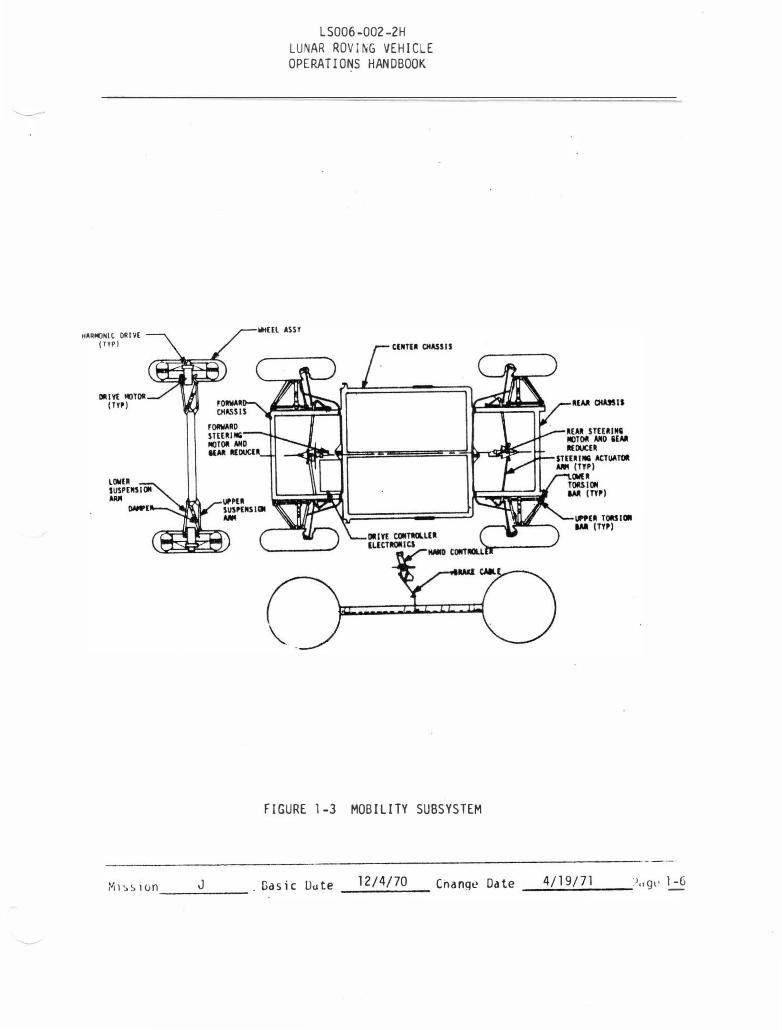
1.3 MOBILITY SUBSYSTEM
The m obility subsystem (figure 1-3) consists of the chassis and equipment and controls necessary to propel, suspend , brake and steer th� LRV.
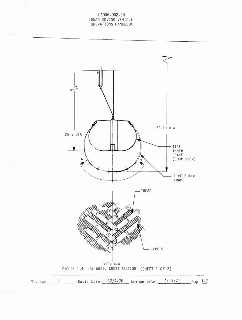
1.3.1 Wheel
Each wheel (figure 1-4, Sh 1) includ es an open wire mesh tire with chevron tr ead covering 50 percent of the surface contact area. The tire inner frame prevents excessive d eflection of the outer wire mesh frame under high impact load cond itions.
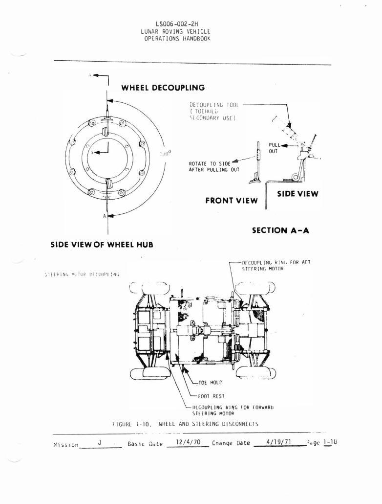
E ach wheel has a d ecoupling mechanism (figure 1-5) and can be d ecoupled from the traction d rive by operating the two d e coupJinq mechanisms (figure l-10) which allows the wheel to "free-wheel" about a bearing ind epend ent of the d rive train. This d ecoupling mechanism can also be used to re-engage the wheel with the traction d rive. Decoupling d isables the brake on the affected wheel.
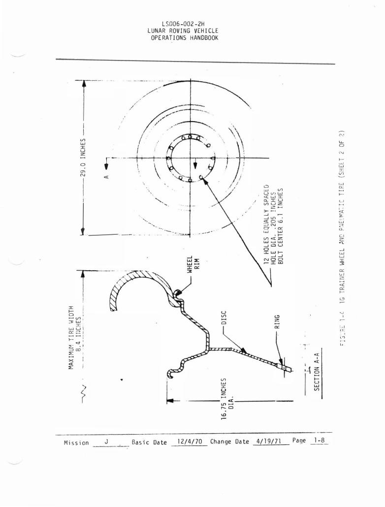
* * * lG Trainer Notes***
1. The 1 G Trainer tires for primary use are pneumatic automobile tires (figure 1-4, Sh 2) Special wire mesh wheels are also avail-abl e for use ·with the lG Trainer.
2. The lG Trainer has simulated wheel d ecoupling mechanisms to d uplicate the LRV-to-Crew interface. Operation of this simulated mechanism, however, will not effeLt actual d ecoupling. Proced ures for lG Trainer wheel d ecoupling are shown in Section 8. Wheel d ecoupling on the lG Trainer d oes not d i sable the brake on the affected wheels.
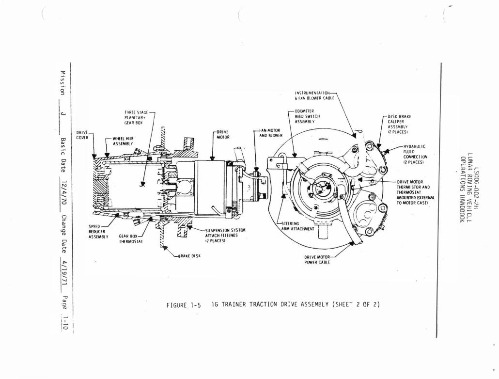
1.3.2 Traction llrive
[cJch wheel is provid ed with a separate traction d rive (figure l-5, Sh 1) consistinq of d harmonic d rive red uctjon unit, d rive motor and brake assembly. Each traction d rive is hern�tically sealed to maintain a 7. 5 PSIA internal pres-sure for improved brush lubrication. Each traction d rive al so contains an od ometer pickup which transmits a pulse to the navigation system signal processing t.nit at the rate of nine pulses per wheel revolution.
Mission J . Basic Date 12/4/70 Change Date __ 4j.JJJ]J.._ Page 1-5
HARI()HIC DRIVE ( TYP)
Ml�!.IOn ___ J __ _
LS006-002-2H LUNAR.ROVING VEHICLE OPERATIONS HANDBOOK
WHUlASSY
FIGURE 1-3 MOBILITY SUBSYSTEM
Gasic Uote ___ 1_2_14_1_7_0 __ _ Cnang� Date __4.;.../ 1_9..;../_7 _1 __ :) .. gt• �
i'il�5lun
LS006-002-2H LUNAR ROVING VEHICLE
OPERATIONS HAN DBOOK
VIEW A-A
32. 1 'l IliA .
......_-�TIRE
RIVETS
I NNER FRAME (BUMP STOP)
TIRE OUTFR FRAME
FIGURE l-4 LRV WHEEL CROSS-SECTION (SHEET 1 OF 2)
-----J ·Basic Oo te __ 1_2/;_4..;./_7_0_ Cnange Date __ 4_1_1 _9/;...?_l __ .,uge 1...:.?
V'l UJ ::I: u z:
0 en N
I
.----
c:(
.,.···
LS006-002-2H LUNAR ROVING VEHICLE OPERATIONS HANDBOOK
/ �-,-; �...,. __ .
I .. -----1 { II
\ -·-t··-·
! /
.1/ w
1 ___ ... �--��-. . _ ... _ ..
/
w V'l U VI UJ c:( UJ ::I: o.::t:U V'l u z:
z ...... >- ..... ....J ....J V) •
c:(O I.O :.::>N CT • 0: I.U UJ
• 1-V'l c:( z:
�---/ !
::I: i b I � Vl: 3 UJ
::I:. UJ U l �::=:I
;: - ; ..,.. :£.: ·' :::J co ::E I >< I � I
Mission
..
J -----'--
L
u V"l
V'l UJ ::I: u :z: ......
UJ ...... UJ ....JWU 0 :I: UJ 1-
....J ....J NOO .-::x:c:o
--------- c:C------------lfl ...... r--0
1.0 .-
Basic Date 12/4/70 Change Date 4/19/71
"-' ..... 0 '" 1-u...J UJ ::I: V)
lLl 0.: �-L)
� ::00. =-· w . . u. Cl z � ....J UJ w ::I: 3 � uJ z ...... c:( � 1-t.:>
...., I
:.I n·
l'l �� . ., lo
' c:(
I c:(
I L� :z: 0 1-u I.LJ V'l
Page 1-8

DECOUPLING MECHANISM
C I RCULI\R SPL WE
•JN I C URI VE
Wf,'VE GENI:.RATOI{
LS006-002-2H LUNAR ROVI�G VEHICLE OPERATIONS HANDBOOK
F REE-WHEE LING 13EARING
DRIVE MOTOR
SUSPENSION SYSTEM ATTACH FITT
.INGS
FIGURf l-5. LRV TI{ACTION UI{!VL ASSEMBLY (SHEE T 1 OF 2)
J Gasic 0dte 12/4/70 Change Date __ 4/:.... 1;..;;9..:../.;..7.;..1 __ ?oge .!.:_9 ."ihsion -----
3: �-"' "'
�
0 ::I
�
I CXl I Ql "' �.
n 0 Ql � nl
_. N ........ � ........ '-J 0
("") ;;r Ql ::I
10 nl 0 Ql � nl
� ....... _.
\0 ....... '-J _.
-o Ql
� nl
_.
,, \c;
DRIVE
COVER
I I
llfRH SlAG£
PlANfl.ARV
f,£AR BOlC
G£,AR
IH£RMOSIAI tl 'BRAKEOISJ.
FIGURE 1-5
fAN MOIOR
AND 8L()II£R
INSIII\JMENIAIION
& fAN BLOWIR r.ABl£
DISK BRAKE
CALIPER
ASSEMBlY
12 PLACES I
HYDARUliC
rtuiD
CONNECIION
12 PLACES I
� ,en'1 DRIV£ MOTOR
lG TRAINER TRACTION DRIVE ASSEMBLY (SHEET 2 OF 2)
TH£RMI STOR AND
THERMOSTAT
lMOOHTID OOlRNAI.
TO MOTOR CASEl
roc: J :z •> ;;o ;v r-> V> --i;;o= -oo 0 <:0' :Z- I V'l :z 0
GlO = N l><l :z mN O:I::C CJ
o n or-?<: r.-
I I
LS006-002-2H LUNAR ROVI�G VEHICLE OPERATIONS HANDBOOK
MOTOR CONTROL CABLE
\,
ODOMETER CABLE
DRIVE MOTOR
HARMONIC DRIVE
FIGURE 1-6. TRACTION DRIVE INSTALLATION
Gas i c 0d te 12/4/70 Change Date _.....: 4 /:.... l_9.:../7...; 1 __ ?ogc 2_:ll
1. 3.2. 1
LSOOb-002-211 LUNAR ROVING VEHICLE
OPERATIONS HANDBOOK
***lG Trainer Notes***
1. The traction drive for the lG Trainer has a 3-stage planetary gear box in lieu of the harmonic drive, (figure 1-5, Sh 2).
2. lG Trainer traction drives are not hermetically sealed.
Harmonic Drive
The four han1mnic drive reduction units transmit torque to each wheel. Input torque to the four harmonic drives is supplied by the four electric drive motors. The harmonic drives reduce the motor speed at the rate of 8 0: 1 and allow continuous application of torque to the wheels at all speeds without requiring gear shifting, Speed/torque/efficiency characteristics of the harmonic drive units are shown in Appendix A.
1. 3. 2. 2 Drive Motor.
The drive motors are direct current series, brush type motors which operate from a nominal input voltage of 36 VDC. Speed control for the motors is furnished by pulse width modulation from the drive controller electronic package. Performance characteristics for the drive motors are shown in Appendix A. Suspension system attach' fittings on each motor also form the king-pin for the LRV steering system. Each motor is instrumented for thermal monitoring. An analog temperature measurement from a thermistor at the stator field is displayed on the control and display panel. In addi-tion, each motor contains a thermal switch which closes on increasing temperature at 4U0°F and provides an input signal to the caution and warning system to actuate the waming flag.
***lG Trainer Notes***
1. The lG lrainer drive motors operate fro111 a nominal input volta�e of 34 VDC.
2. The lG Trainer gear hox th0rmal switch will actuate the warning flag when a gear box temperature reaches 20 0 °�. The indicated temperature, however, will be 450°F to 50 0 °F upon actuation, since the readouts are biased.
3. The lG Trainer motor temperature switch i� set to actuate the flag when the motor external case temperature reaches 225°F. This temperature at the case would correspond to a rotor temperature of about 450 °F.
Mission __ .J._ __ Basic Date 12/4/70 Change Date 4/19/71 Page 1-12
1.3.2.3 13rakes
LS006-002-2H LUNAR ROVING VEHICLE
OPERATIONS HANDBOOK
Each traction drive is equipped with a mechanical brake actuated by a cable connected to a linkage in the hand controller. Stopping distance capability using these brakes is shown in Appendix A.
Braking is accomplished by moving the hand controller rearward. This operation de-energizes the drive motor and, through a l inkage and cable, forces brake shoes against a brake drum which stops the rotation of the wheel hub about the harmonic drive.
1. 3. 3
***lG Trainer Note***
The lG Trainer brakes are hydraulically actuated disc brakes. Brakes are actuated by the hand controller in the same manner as the LRV mechanical brakes.
Suspension
The chassis ( figure 1-7) is suspended from each wheel by a pair of parallel triangular arms connected between the LRV chassis and each traction drive.
Loads are transmitted to the chassis through each suspension arm to a separate torsion bar for each arm . . Wheel vertical travel and rate of travel is limited by a linear da�per connected between the chassis and each traction drive. The deflection of the suspension system and tires combine to allow 14 inches of chassis ground clearance when the LRV is fully loaded and 17 inches when unloaded.
Damping energy heats the fluid in the damper. The heat is conducted from th� fluid to the damper walls for dissipation.
The suspension systems can be rotated approximately 135 degrees to allow folding and LRV stowage in the LM.
Mission J
***lG Trainer Notes***
1. lG Trainer suspension is not designed to allow folding for LM stowage.
2. lG Trainer suspension system contains only a lower torsion bar on each wheel.
Basic Date 12/4/70 Change Date 4/19/71 ----Page 1-13
I I
======j::
Vl (..!) ::E z a::
c:( 1-1--� Vl Vl Vl c:( :r: u
LSOOG-002-211 LUNAR ROVl�G VEHICLE OPERATIONS HANDBOOK
� 0:: ...... w Vl :xa::a:: coer ....J 1- co
I � I
a:: ..... � .w Vl
a.. 0:: a::
a.. ocr ::> 1- co
0:: w a.. ::E c:( 0
" \
' ·) rj >-....J co :;:: - w Vl Vl c:( z 0 ...... Vl z: w a.. Vl :::::> Vl
,..... I
w 0:: :::::> (..!) ...... LL..
t'r1:.SJon ___ J __ Gas i c Date 12/4/70 Change Date __ 4�/l--9..:.../7� 1 __ .:J,,9L' !.:_!4
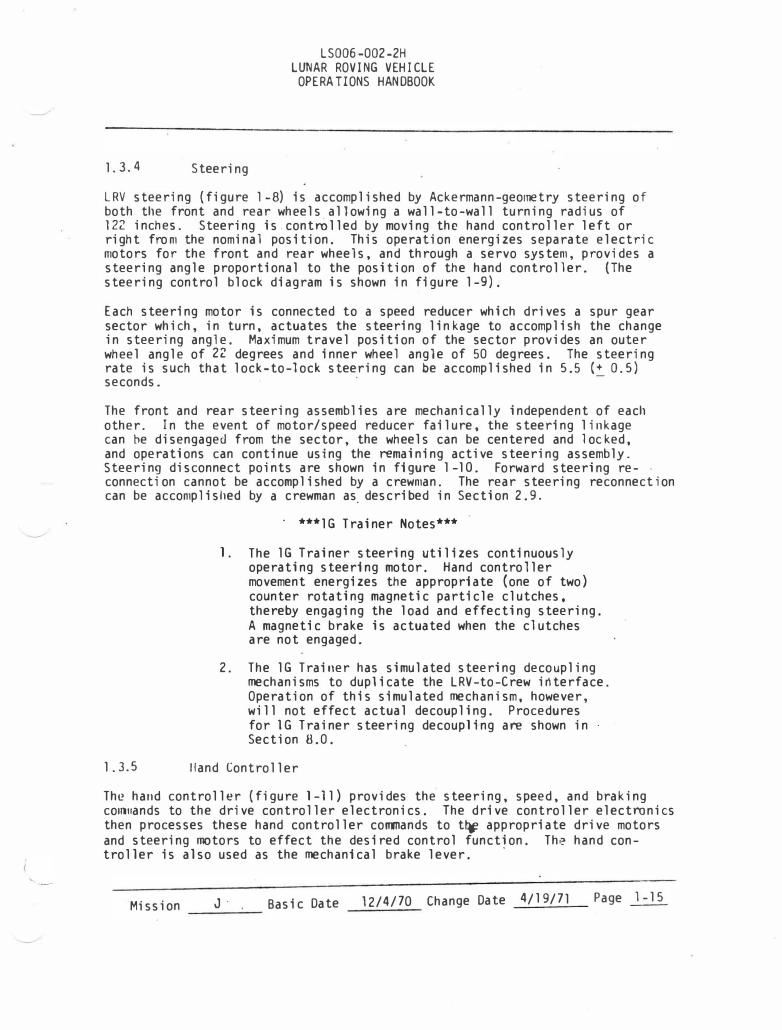
1. 3. 4 Steering
LS006-002-2H LUNAR ROVING VEHICLE
OPERATIONS HANDBOOK
LRV steering (figure l-8) is accomplished by Ackermann-geometry steering of both the front and rear wheels allowing a wall-to-wall turning radius of 122 inches. Steering is.controlled by moving the hand controller left or right from the nominal position. This operation energizes separate electric motors for the front and rear wheels, and through a servo system, provides a steering angle proportional to the position of the hand controll er. (The steering control block diagram is shown in figure l-9).
Each steering motor is connected to a speed reducer which drives a spur gear sector which, in turn, actuates the steering linkage to accomplish the change in steering angle. Maximum travel position of the sector provides an outer wheel angle of 22 degrees and inner wheel angle of 50 degrees. The steering rate is such that lock-to-lock steering can be accomplished in 5.5 (+ 0. 5) seconds. · -
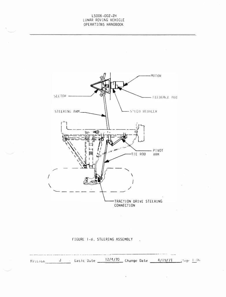
The front and rear steering assemblies are mechanically independent of each other. In the event of motor/speed reducer failure, the steering linkage can be disengaged from the sector, the wheels can be centered and locked, and operations can continue using the remaining active steering assembly. Steering disconnect points are shown in figure 1-10 . Forward steering reconnecti on cannot be accomp 1 i shed by a crewman. The rear steering reconnect ion can be accomplished by a crewman as. described in Section 2.9.
· * * * lG Trainer Notes* * *
1. The lG Trainer steering utilizes continuously operating steering motor. Hand controller movement energizes the appropriate (one of two) counter rotating magnetic particle clutches, thereby engaging the load and effecting steering. A magnetic brake is actuated when the clutches are not engaged.
2. The lG Trainer has simulated steering decoupling mechanisms to duplicate the LRV-to-Crew interface. Operation of this simulated mechanism, however, will not effect actual decoupling. Procedures for lG Trainer steering decoupling are shown in· Section 8.0.
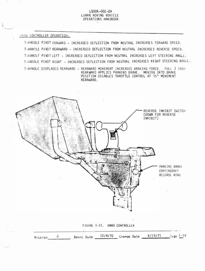
1. 3. 5 Hand Controller
The hand controller (figure l-11) provides the steering, speed, and braking conlnands to the drive controller electronics. The drive controller electronics then processes these hand controller commands to t� appropriate drive motors and steering motors to effect the desired control function. The hand con-troller is also used as the mechanical brake lever.
·
Mission J · Basic Date 12/4/70 Change Date 4/19/71 -----
Page 1-15
I
\
LS006-002-2H LUNAR ROVING VEHICLE OPERATIONS HANDBOOK
_,---MOl OR
�LC TOR -----"
........_ _
..........
\''1 Lll IH.IJIILLR
---PIVOT TIE ROO ARM
\
I /
-
TRACTION DRIVE STElRING CONNECTION
fiG URE 1-U. STeERING ASSEMBLY
----- - - - - -- -----·- - --------- ----·--------------· - ---
1"1:.�1un ___ J __ . f.jasic Uute 12/4/70 Change Date _ __;.4:....1 ;..;1'J�I...;..J...;..l __ .• ,,,J•· .!..:_II.

I� VOL 1 POWlk
EMI F I L T[R
ERROR AMPLI rl ER AltO STAB I ll Z I NG
N[TWOR�
[M1 r I L HR
� PWH
� POWER ORI VER
I �ERVO AMPLlflfP ASSEMBLY
( IN OCl)
CrH1ANl•
1'(111 N 1 111M I 1 I II
HAN[' CON 1 ROLLI�
LS006-002-2H LUNAR ROVING VEHICLE
OPERATI9NS HANDBOOK
- 36 VOLT POWEll l
HEDBAU POT
SPLIT riELD r+ SPEED REDUCER
I
Sllli!ING ANGU
COMMAND UN I 1
I
DC MOTOR
I STEERING MOTOR ASSEMBLY 1
I +
)JllRINL I INKA(,I
fiGURE 1-9. STEERING CONTROL BLOCK DIAGRAM
Ml�Slun _____ J ____ ___ Casic Date 12/4/70 Cnange Date __ 4.;../_19 ..;./�7� 1
__ .>.,ge � 7
'I
LS006-002-2H LUNAR ROVING VEHICLE
OPERATIONS HANDBOOK
WHEEL DECOUPLING
DECOUPL I NG TOOL ( TOEIILILiJ '>I CONDI\RY USE)
ROTATE TO SIDE� : AFTER PULLING OUT
FRONT VIEW
SECTION A-A SIDE VIEW OF WHEEL HUB
:.lllfJiNI, Mllllil-' lil(lllll'llN!;
FOOl R(ST
IJLCOUPLINC. IU'1C. fOR fORWARil
�TI£RING MOTOk
IIGlJHL 1-10. WIII:.I-.L ANU STLERING UISCONNtCl�
."'i1 s s 1 on ___ J __ _ Basic Du te 12/4/70 Cnanqe Date _ __,4/_1_9 .... 1_7_1 __ .Jogt? .!..:]13
t '
11/,;W C.OrHROLLER OPE RATION:
LS006-002-2H LUNAR. ROVING VEHICLE
OPERATIONS HANDBOOK
T -HANDLE PIVOT FORWARD - INCREASED DEFL ECTI O N FROM NEUTRAL INCREASES F ORWARD SPE ED.
T-HAN�LE PIVOT REARWARD- INCREASED DEFLECTION FROM.
NEUTRAL INCREASES REVERSE SPEED.
T -f:ANCLF PIVOT LEFT - INCREASED DEFLECTION FROM NEUTRAL INCREASES LEFT STEE RING ANG LE.
T -I:ArWLE PIVOT RIG HT - INCREASED DEFLECTION FRO.M NEUTRAL INCREASES RIGHT STEERING MGLl.
T -HANDLE DISPLACED REARWARD - REARWARD MOVEMENT 1 NCREASES BRAKING F ORCE. FULL 3 JrJCII
M)SSion __ J __ _
REARWARD APPLIES PARKING BRAKE . f.'OV ItiG INTO BRAK E POSITION DISABLES THROTTLE CONTROL AT 15° MOVEME NT REARWARD.
F I GliiU:. 1-11 • HAND CONTROLLl R
REVERSE INHIBIT SWITCH (DOWN FOR REVERSE INHIBIT)
PARKING BRAKt. CONTINGENCY RE LE ASE RING
Basic Dote 12/4/70 Cnange Date 4/19/71 Juge !..:J9 ------
l . 3 . 5 . 1 Speed Con trol
LS006-002 -2H LUNAR ROV I NG VEH I CLE
OPERATIONS HANDBOOK
Forward mo vemen t of the han d con tro ller abo ut the T-hand le thro ttle p i vot ax i s p roport i on a t e l y i nc re ases fo rua r d sp eed. A n eut r a l dead band ex i st s for abo u t t h e fi rs t 1 . 5 degrees o f forward mo t i on . A cons t a n t t o 1 � ue o& abo u t 6 i n c h pounds i s req u i red t o move the hand c o n t ro l l e r beyond the l i mi t of the dead band ( f i gu re 1 - 1 2 ) . Tile n i ne degree pos i ti on corresponds to a p u l s e duty cyc l e of a p p ro x i ma t e l y 50 �ercen t , at ea ch dri ve mo t o r, i . e . , the motors a re a t 50 percent of ma x i mum s peed condi t i on . The ma x i mum power s e t t i ng i s il r h i e ved hy p i vo t i nc the h a n d c o · 1 t ro l l e r to the h a rd s top ( ma x i murn� pos i t i on , 1 t <�p p ro x i mil t e l y 1 4 df'qrees . To dece l era te , thP h d n d c on t ro l l r r i s p i vo ted t·e ; u-wil rd . Tht:> torqUL'S rf'q u i rec1 o t rP shown i n f i q u rf' 1 - 1 1. . To p l ace th e veh i l l e i n neu t t ·a l . the h , 1nd con l rr. l l e r i s p i voted rearward to the z e ro ( + l i 2 ) d e q re<' pos i t i o1 1 .
-
Wi t h the re ve rs e i n h i b i t s�oli t ch i n the down pos i t i o n , the hand con t ro l l e r c a n b e p i voted forward on l y , there by preven ti n g i na d ve r ten t l y p l a c i ng the veh i c l e i n re verse .
To operate the veh i cl e i n revers e , the re ve rs e i nh i b i t swi tch i s p l aced i n the u p pos i ti on and the h a n d c o n t rol l e r p i voted rearward about the thro t t l e p i vot po i n t . Torque vs . di s p l acemen t cha racteri st ics for reverse a re i de n t i c a l t o forward s peed ope r a t i on a s s h own by f igure 1 -1 2 .
T h e veh i l l e mus t be brou�h t to il fu l l s top before a di re c !. i on c h a n qe i s convnJ n <.ll' d . D i rer ti <. n ch a nqe i '> au toma t i cd l l y i nh i b i ted a t veh i c l e s peeds q rea.te r than l KPH .
The hand con tt·o l l e r wi l l rema i n i n th e !i C l e c te d forward or reverse s peed j.Jos i t i on i n th e crewmen " h an d s off" cond i t i on .
1 . 3 . 5 . 2 Stee1· i n g Control
P i vo t i rHJ the har rd con t ro l l e r l e f t o r r i g h t abo u t the rol l p i vo t po i n t prop o r t i on il l l y c hr1 1 1 � 1es t h e wheel s te e ri ng ang l e . The s te e r i r 1g con t ro l , l i ke t i le t h r o t t l e r o n t 1·ol . ll<�s rl 1 / 2 degree n e u t ra l dead band on e i ther s i de of : \ ' rt' . ( See f i q u t-e l - 1 3 ) . 1\ tOrCJue of 7 i n - l bs . i s req u i red to rol l the l l . I IHI con t ro l l e r beyond the n e u t ra l p os i t i on to beg i n s teeri ng anq l e ch <mge . Torque t·equirr.d for i nc reas i ng the di s pl acement a n g l e .1bout ::he ro ll p i vot po i n t i nc re as es I i ne t:.� ril l l y un t i l a d i splace ment of il p p rox i ma te l y 9 degrees i <; ,-e ,h :l le d . 1\t the 9 degr�>e pos i t i on , a s o ft sto p i s en coun tered wh i ch req u i re�, " .; te J l - fun c l i on t orque i nc rc c1 s e o f 5 i n - l bs . to p i vo t the h and cont rol l e r f u r t l ll' r outllo,Jrcl f o r i n c: re a s i n g t h e s teer i n g angle. After pa s s i n g th•= s o f t s toj.J
M i s s i on J Bas i c lJate
- - ------------
1 2/ 4 / 7 0 Change Da te 4 / 1 9/ 7 1 Page l -�0