Embed Size (px)
Citation preview

ZX100
ZX100
5 L Z E CK1
5 L Z E CK3
5 L ZK1ZX100
Valve unitN.O. type
Vacuum switchunit
Valve unitN.C. type
Vacuum switchunit
FValve unitN.C. type
Filterunit
Combin
ation o
f supp
ly valv
e
and r
elease
valve
Pilot v
alve
Electri
cal e
ntry
Light
/Sur
ge vo
ltage
su
ppre
ssor
Man
ual o
pera
tion
Vacuu
m sw
itch
unit
Filter u
nit
Vacuu
m sw
itch
Electri
cal e
ntry
PV/V p
ort s
ize
NilDC: 1 W
(With indicator light: 1.05 W)AC
Y ∗DC: 0.45 W
(With indicator light: 0.5 W)
PV/V port size
NilY
M5 x 0.8M6 x 1 (Option)
1 ∗
3 ∗100 VAC 50/60 Hz110 VAC 50/60 Hz
5 24 VDC 6 12 VDC V 6 VDC S 5 VDC R 3 VDC
NilAir operated
(K6, K8, J3, J4, D3, D4)
Manual operation
NilB
Non-locking push typeLocking slotted type
Light/Surge voltage suppressor
Nil
S ∗
None
Z With light/surge voltage suppressor
With surge voltage suppressor
Vacuum switch unit/Filter unit
EPSPBF
Vacuum switch (For general purpose)Nozzle dia. (ø0.3 to 0.7)Nozzle dia. (ø0.5 to 1.2)
Only suction filter
With suctionfilter
Adsorption confirmation switch
Vacuum switch electrical entry
NilL
Lead wire length 0.6 mGrommettype
Connectortype
Lead wire length 3 mC Lead wire length 0.6 m
CL Lead wire length 3 m
CNWithout connector(Without lead wire)
• Refer to “Table (2)” on page 13-2-41 for part number of lead wire with connector.
Vacuum digital pressure switch unit
D21222324
DP
2 outputs/without analog output2 outputs/with analog output
1 output (with trouble detection)/without analog1 output (with trouble detection)/with analog
kPa
LLN
Lead wire length 0.3 m
Plugconnector
type
Without lead wire (Applicable to DC only)
MNMO
Without lead wire (Applicable to DC only)
Grommettype
GHNil
Without connectorLead wire length 0.3 m (Applicable to DC only)Lead wire length 0.6 m (Applicable to DC only)
Air operated
LO Without connectorM Lead wire length 0.3 m
Note) Analog output is available on grommet type only.
Note) In the case of “K1” (combination of supply and release valves), M type plug connector can not be used.
Electrical entry
Voltage
∗ Applicable to plug connector.(Connector assembly with rectifier is attached.)
Pilot valve
Valve unit/Combination of supply valve andrelease valveRefer to “Table (1)” on page 13-2-41.
∗ 24 VDC and 12 VDC are applicable to 0.45 W.
• Refer to page 13-2-54 for ordering the manifold.
• Refer to page 13-2-64 to 65 for ordering a unit for replacement.
Components
Voltag
e
• Refer to “Table (3)” on page 13-2-41 for part number of lead wire with connector.
How to Order
Caution
Caution
When using the AC type, the DC solenoids are operated via a rectifier. Therefore, when using this type, make sure to combine the connector assembly equipped with a rectifier with the exclusive solenoids. Using other combinations could lead to burned coils or other types of malfunctions.
Surge voltage suppressorUsing the DC type:Match the polarity of the connectors according to the + and – marks on the connectors. Do not interchange the polarities to prevent the diodes or the switching elements from becoming burned.If lead wires are pre-connected, the red wire is + and the black wire is – .Using the AC type:The AC type is not equipped with a surge voltage suppressor because the rectifier assembly prevents the generation of surge voltage.
Light/Surge voltage suppressor
Red
Black
Dio
de
Coi
l
Coi
l
Vacuum Module:Vacuum Pump System
Series ZX
∗ In the case of AC, “S” is not available.
13-2-40
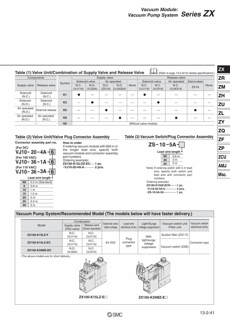
Table (1) Valve Unit/Combination of Supply Valve and Release Valve
How to orderIf ordering vacuum module with 600 m or the longer lead wire, specify both vacuum module and connector assemby part numbers. Ordering example)ZX100-K15LOZ-EC······1 pc.∗VJ10-20-4A-6·············· 2 pcs.
Connector assemby part no.
Table (2) Valve Unit/Valve Plug Connector Assembly Table (3) Vacuum Switch/Plug Connector Assembly
Note) If ordering switch with 5 m lead wire, specify both switch and lead wire with connector part numbers.
Ordering example) ZX100-K150Z-ECN·········1 pc.∗VJ10-20-4A-6··············· 2 pcs.∗ZS-10-5A-50················· 1 pc.
ZX100-K15LZ-E� ZX100-K35MZ-E�
Components
Supply valve
Solenoid (N.C.)
Solenoid (N.C.)
Solenoid (N.O.)
Solenoid (N.C.)
Air operated (N.O.)
External release
Air operated (N.O.)
Air operated (N.C.)
Release valveSymbol
K1 �
—
—
—
—
�
—
—
—
—
�
—
—
—
—
�
—
—
—
—
�
—
—
—
—
�
—
—
—
—
—
�
—
—
�
—
—
—
—
—
K3
K6
K8
Nil Without valve module
Solenoid valveSupply valve Release valve
N.C. (VJ114)
N.O. (VJ324)
Air operatedN.C.
(ZX1A) N.O.
(VJA324)
Solenoid valveN.C.
(VJ114) N.C.
(VJ314)
Air operated External releaseN.C.
(VJA314) ZX1A
None None
3A36VJ10
Nil6
1015202530
0.3 m (Standard)0.6 m1 m1.5 m2 m2.5 m3 m
1A36VJ10
(For DC)
(For 100 VAC)
(For 110 VAC)
4A20VJ10 6
6
6Lead wire length
Nil3050
5A10ZSLead wire length
24 VDC Connector typePlug
connectortype
With light/surge
voltage suppressor
Solenoid valverated voltage
Lead wireelectrical entry
Light/Surgevoltage suppressor
Vacuum switch unit/Filter unit
Vacuum switchelectrical entry
CombinationSupply valve(Pilot valve)
N.C. (VJ114)
N.C. (VJ114)
N.O. (VJ324)
N.C. (VJ114)
Suction filter (ZX1-F)
Vacuum switch (ZSE)
N.C. (VJ114)
N.C. (VJ314)
Release valve(Direct operated)
Model
ZX100-K15LZ-F
ZX100-K15LZ-EC
ZX100-K35MZ-EC
∗The above models are for short delivery.
Vacuum Pump System/Recommended Model (The models below will have faster delivery.)
(Refer to page 13-2-42 for details specifications.)
0.6 m3 m5 m
Series ZX
13-2-41
Vacuum Module:Vacuum Pump System
ZX
ZR
ZM
ZH
ZU
ZL
ZY
ZQ
ZF
ZP
ZCU
AMJ
Misc.
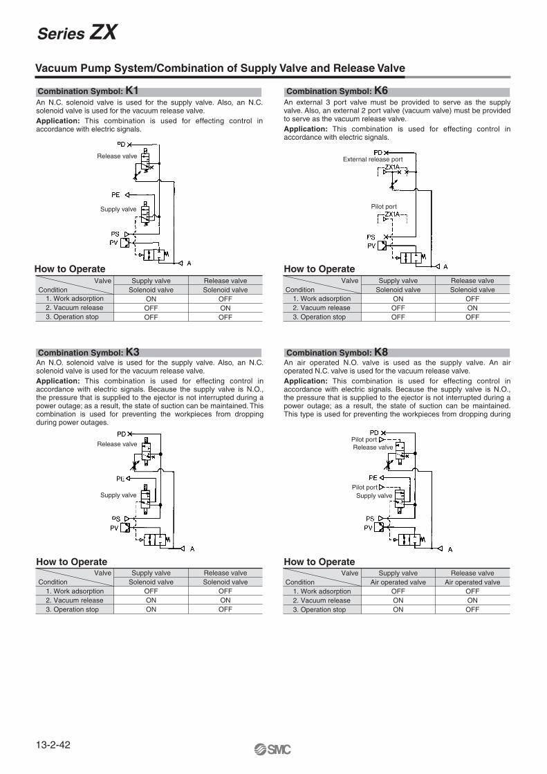
Vacuum Pump System/Combination of Supply Valve and Release Valve
Combination Symbol: K1
How to Operate
Combination Symbol: K6
How to Operate
Combination Symbol: K3
How to Operate
Combination Symbol: K8
How to Operate
An N.C. solenoid valve is used for the supply valve. Also, an N.C. solenoid valve is used for the vacuum release valve.Application: This combination is used for effecting control in accordance with electric signals.
An N.O. solenoid valve is used for the supply valve. Also, an N.C. solenoid valve is used for the vacuum release valve.Application: This combination is used for effecting control in accordance with electric signals. Because the supply valve is N.O., the pressure that is supplied to the ejector is not interrupted during a power outage; as a result, the state of suction can be maintained. This combination is used for preventing the workpieces from dropping during power outages.
An air operated N.O. valve is used as the supply valve. An air operated N.C. valve is used for the vacuum release valve.Application: This combination is used for effecting control in accordance with electric signals. Because the supply valve is N.O., the pressure that is supplied to the ejector is not interrupted during a power outage; as a result, the state of suction can be maintained. This type is used for preventing the workpieces from dropping during
Supply valveSolenoid valve
ONOFFOFF
OFFONOFF
Solenoid valveRelease valveValve
Condition1. Work adsorption2. Vacuum release3. Operation stop
Supply valveSolenoid valve
ONOFFOFF
OFFONOFF
Solenoid valveRelease valveValve
Condition1. Work adsorption2. Vacuum release3. Operation stop
Supply valveSolenoid valve
OFFONON
OFFONOFF
Solenoid valveRelease valveValve
Condition1. Work adsorption2. Vacuum release3. Operation stop
Supply valveAir operated valve
OFFONON
OFFONOFF
Air operated valveRelease valveValve
Condition1. Work adsorption2. Vacuum release3. Operation stop
An external 3 port valve must be provided to serve as the supply valve. Also, an external 2 port valve (vacuum valve) must be provided to serve as the vacuum release valve.Application: This combination is used for effecting control in accordance with electric signals.
Release valve
Supply valve
External release port
Pilot port
Release valve
Supply valve
Pilot port
Pilot port
Release valve
Supply valve
Series ZX
13-2-42

Vacuum Pump System/Construction
Component Parts
Table (3) How to Order Air Operated Valves
Replacement Parts
Table (1) How to Order Pilot Valves
Table (2) How to Order Solenoid Valves
CautionTurning the vacuum release flow volume adjusting needle clockwise reduces the vacuum release flow volume; the needle valve is fully closed when the needle stops turning. Turning the needle 2 full turns counterclockwise from the fully closed position renders the needle valve fully open. The needle will fall out if it is turned more than 4 full turns.
Material—
Stainless steelAluminum
———
Stainless steelPolycarbonate
NoteZX1-PV-O
ZSE2, ZSP1
(PV)/(PS PD)
No. Descriptionq
w
e
r
t
y
u
iNote)
Poppet valve assemblyRelease flow rate adjusting needleManifold baseVacuum switchValve unitInterface plateReturn springFilter case
Material
PVF—
Part no.Refer to “Table (2)”, “(3)”.
ZX1-FE
No. Description
!0
o
Filter elementPilot valve
Note) Caution when handling filter case1. The case is made of polycarbonate. Therefore, do
not use it with or expose it to the following chemicals: paint thinner, carbon tetrachloride, chloroform, acetic ester, aniline, cyclohexane, trichloroethylene, sulfuric acid, lactic acid, watersoluble cutting oil (alkalinic), etc.
2. Do not expose it to direct sunlight.
Solenoid valve Air operatedAir operated Solenoid valve
No. 2 and 3 models only are applicable.Indicate each part number.
Combination of supplyand release valve
ZX1-VJ3 4�-����
ZX1-VJA3 4
ZX1-VJ114-���� K1, J1
K3, J2
K6
ModelNo.Component equipment
1
2
3
4
Supply valve Release valveSolenoid valve N.C. (VJ114)
Solenoid valve N.O. (VJ324)
Air operated N.O. (VJA324)
Solenoid valve N.C. (VJ114)
Solenoid valve N.C. (VJ314)
Air operated N.C. (VJA314)
12
12
ZL5ZX1-VJ114
ZL42 5ZX1-VJ3
Light/Surge voltage suppressorManual override
Electrical entry
Rated voltage
Nil
DC: 0.45 W(With indicator light: 0.5 W)
AC
DC: 1 W(With indicator light: 1.05 W)
Y ∗
∗ 24 VDC and 12 VDC are applicable to 0.45 W.Note) Screw length of VJ100 and VJ300 for series ZX
is different from that of the standard model.<Screw length> VJ100–M1.7 x 15
Pilot valve
Note) In the case of N.C. type, indicate no symbol. (Individual exhaust for Pilot valve)
Note) In the case of ZX1-VJ114, M, MN and MO cannot be used.
NilB
Non-locking push typeLocking slotted type1
2N.C. (Normally closed)N.O. (Normally open)
NilS
Without light/surge voltage suppressorWith surge voltage suppressor
Z With light/surge voltage suppressor
1 ∗
3 ∗100 VAC110 VAC
5 24 VDC6 12 VDCV
Nil Pilot valveIndividual exhaust
M Common exhaust formain and pilot valves
6 VDCS 5 VDCR 3 VDC
∗ Applicable to plug connector
LLN
Connector (0.3 m)Connector (W/o lead wire)
LO Without connectorM Connector (0.3 m)
MN Connector (W/o lead wire)MO Without connectorG Grommet (0.3 m)H Grommet (0.6 m)
M3M5
M3 x 0.5 Pilot port/External release portM5 x 0.8
Port size
M3ZX1A
ZX1-VB������-D-�
Type of actuation Body option
Series ZX
13-2-43
Vacuum Module:Vacuum Pump System
ZX
ZR
ZM
ZH
ZU
ZL
ZY
ZQ
ZF
ZP
ZCU
AMJ
Misc.
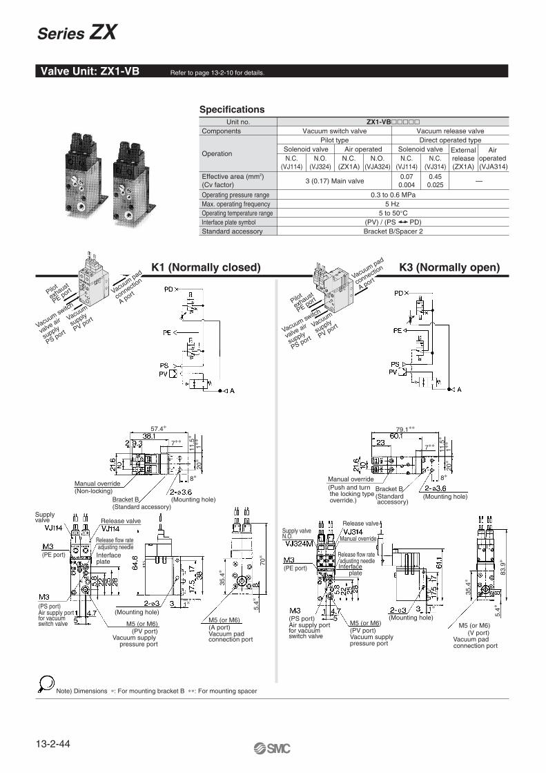
Specifications
K1 (Normally closed) K3 (Normally open)
Unit no. ZX1-VB�����Components
Operation
Effective area (mm2) (Cv factor) 3 (0.17) Main valve —
Operating pressure range 0.3 to 0.6 MPa5 Hz
5 to 50°C
Bracket B/Spacer 2
Max. operating frequencyOperating temperature rangeInterface plate symbolStandard accessory
Vacuum switch valve Vacuum release valveDirect operated typePilot type
Solenoid valve Solenoid valveAir operatedN.C.
(VJ114) N.O.
(VJ324) N.C.
(VJ114) N.C.
(VJ314)
0.070.004
0.450.025
Externalrelease(ZX1A)
N.C. (ZX1A)
N.O. (VJA324)
Air operated (VJA314)
(PV) / (PS PD)
Valve Unit: ZX1-VB Refer to page 13-2-10 for details.
Note) Dimensions ∗: For mounting bracket B ∗∗: For mounting spacer
Pilot
exhaust
PE port
Vacuum switch
valve air
supply
PS port
Vacuum
supply
PV port
Vacuum pad
connectio
n
A portPilot
exhaust
PE port
Vacuum switch
valve air
supply
PS port
Vacuum
supply
PV port
Vacuum pad
connection
A port
Manual override(Non-locking)
57.4∗
8∗
7∗∗
11.5
∗20
∗1∗
∗
Bracket B(Standard accessory)
(Mounting hole)
Bracket B(Standard accessory)
(Mounting hole)
(Mounting hole)
Supply valve Release valve Release valve
(PE port)
(PE port)
Release flow rateadjusting needle
Release flow rateadjusting needle
Manual override
Interfaceplate
Interfaceplate
(PS port)Air supply portfor vacuumswitch valve
(PS port)Air supply portfor vacuum switch valve
M5 (or M6)(PV port)Vacuum supply pressure port
M5 (or M6)(PV port)
Vacuum supply pressure port
(Mounting hole)1∗
35.4
∗
5.4∗
70∗
M5 (or M6)(A port)Vacuum padconnection port
Manual override(Push and turn the locking type override.)
79.1∗∗
7∗∗
8∗
20∗
1∗∗
11.5
∗
1∗
Supply valve N.O.
M5 (or M6) (V port) Vacuum pad connection port
5.4∗
35.4
∗
83.9
∗
Series ZX
13-2-44
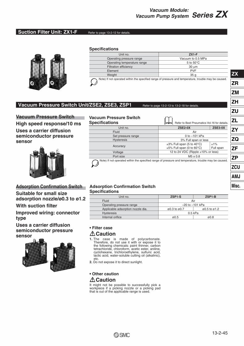
Specifications
Caution1. The case is made of polycarbonate.
Therefore, do not use it with or expose it to the following chemicals: paint thinner, carbon tetrachloride, chloroform, acetic ester, aniline, cyclohexane, trichloroethylene, sulfuric acid, lactic acid, water-soluble cutting oil (alkalinic), etc.
2. Do not expose it to direct sunlight.
• Filter case
CautionIt might not be possible to successfully pick a workpiece if a picking nozzle or a picking pad that is out of the applicable range is used.
• Other caution
Unit no.Operating pressure range Operating temperature rangeFiltration efficiencyElementWeight
ZX1-FVacuum to 0.5 MPa
5 to 50°C30 µmPVF35 g
Note) If not operated within the specified range of pressure and temperature, trouble may be caused.
Vacuum Pressure Switch Specifications
Unit no.FluidSet pressure rangeHysteresis
Accuracy
VoltagePort size
ZSE2-0X ZSE3-0X
±1% Full span
Air0 to –101 kPa
3% Full span or less±3% Full span (5 to 40°C)±5% Full span (0 to 60°C)
12 to 24 VDC (Ripple ±10% or less)
M5 x 0.8Note) If not operated within the specified range of pressure and temperature, trouble may be caused.
Vacuum Pressure SwitchHigh speed response/10 msUses a carrier diffusion semiconductor pressure sensor
Adsorption Confirmation SwitchSuitable for small size adsorption nozzle/ø0.3 to ø1.2With suction filterImproved wiring: connector typeUses a carrier diffusion semiconductor pressure sensor
Adsorption Confirmation Switch Specifications
Unit no.FluidOperating pressure range Applicable adsorption nozzle dia.
Internal orificeHysteresis
ZSP1-S ZSP1-BAir
–20 to –101 kPaø0.3 to ø0.7 ø0.5 to ø1.2
ø0.5 ø0.80.5 kPa
Suction Filter Unit: ZX1-F Refer to page 13-2-12 for details.
Vacuum Pressure Switch Unit/ZSE2, ZSE3, ZSP1 Refer to page 13-2-13 to 13-2-18 for details.
Refer to Best Pneumatics Vol.16 for details.
Series ZX
13-2-45
Vacuum Module:Vacuum Pump System
ZX
ZR
ZM
ZH
ZU
ZL
ZY
ZQ
ZF
ZP
ZCU
AMJ
Misc.

Valve Unit: Type K1
Vacuum switch (ZSE2)ZX100-K1���-E�
Note) Dimensions ∗: For mounting bracket A ∗∗: For mounting spacer 1.
Configuration and combination Valve unit (K1) +
ModelZX100 —— K1���� ——
Vacuum switch (ZSE2)Vacuum switch (ZSE3)Adsorption confirmation switch (ZSP1)
Filter unit (F)
E�D�P��F
Vacuum switch (E)
Adsorption confirmation switch (P)
Filter unit (F)
Circuit diagram(Circuits other than those with vacuum switch are shown as below.)
Pilot
exhaust
PE port
Vacuum switch
valve
air supply
PS port
Vacuum
supply
PV port
Vacuum pad connection
V port
(Release to atmospheric pressure)
Pressure sensor
Spacer 1(For side mounting)
Manual overridePressure setting trimmer
41∗
1∗∗
51∗
2-R1.8∗(Mounting hole)
1∗ 10∗
19∗17.6∗
13.6∗
ø3.6∗(Mounting hole)
Supply valve Release valve
(PD port)
Interfaceplate
Release flow rateadjusting needle
(PE port)
(PS port)Air supply portfor vacuum switch valveM5 (or M6)(PV port)Vacuum supply pressure port
Pitch = 10
Vacuum switch
(Mounting hole)
15.5
∗
4∗
(68.
6)∗
∗∗
Bracket A(Standard accessory)
M5 (or M6)Vacuum pad
connection port
Series ZX
13-2-46

Adsorption confirmation switch (ZSP1)ZX100-K1����-P��
Vacuum switch (ZSE3)ZX100-K1����-D��
Spacer 1: ZX1-S1
Filter unit (F)ZX100-K1����-F
Manual override(Non-locking)
DOWN button
UP button
Spacer 1(For side mounting)
RESET button
SET button
2-R1.8∗(Mounting hole)
∗1 10∗
19∗22.6∗
18.7∗
ø3.6 ∗ (Mounting hole)
41
∗
1∗∗
51
∗
Supply valve
(N.C.)
Release valve
(N.C.)Release flow rateadjustment needle
Interfaceplate
Air supply pressure port(M3, PS port)
(PE port) (PV port)Vacuum supply pressure port
Pitch = 10
(Mounting hole)
M5(V port)Vacuum padconnection port
Bracket A(Standard accessory)
Phillips screwM2.5 x 51
18
∗∗
15
.5∗
∗ 4
Adjustment needle
2-R1.8∗(Mounting hole)
1∗ 10∗ 17.8∗
19∗
ø3.6∗(Mounting hole)
ø3.6(Mounting hole)
Adsorption confirmation switch
Adsorption nozzlepiping portM5 x 0.8(or M6 x 1)
2-ø3.3 mounting hole
ø3.6∗(Mounting hole)
2-R1.8∗(Mounting hole)
1∗ 10∗
19∗ 8.8∗4.8∗
41∗
1∗∗
51∗
(Mounting hole)
Filter
Series ZX
13-2-47
Vacuum Module:Vacuum Pump System
ZX
ZR
ZM
ZH
ZU
ZL
ZY
ZQ
ZF
ZP
ZCU
AMJ
Misc.
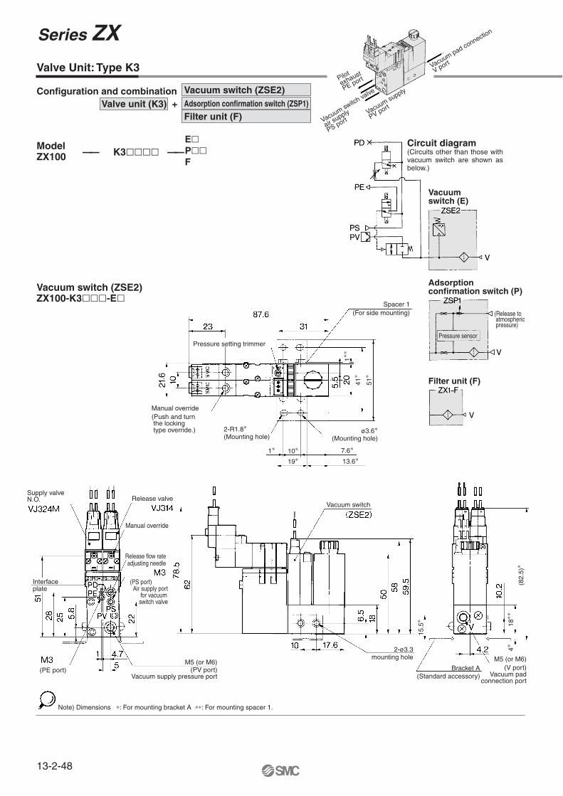
Valve Unit: Type K3
Note) Dimensions ∗: For mounting bracket A ∗∗: For mounting spacer 1.
Vacuum switch (E)
Adsorption confirmation switch (P)
Filter unit (F)
Vacuum switch (ZSE2)ZX100-K3���-E�
Configuration and combination Valve unit (K3) +
ModelZX100 —— K3���� ——
Vacuum switch (ZSE2)Adsorption confirmation switch (ZSP1)
Filter unit (F)
E� P�� F
Circuit diagram(Circuits other than those with vacuum switch are shown as below.)
Pilot
exhaust
PE port
Vacuum switch va
lve
air supply
PS portVacuum supply
PV port
Vacuum pad connection
V port
Spacer 1(For side mounting)
Pressure setting trimmer
Manual override(Push and turn the locking type override.) 2-R1.8∗
(Mounting hole)
1∗ 10∗
19∗7.6∗
13.6∗
ø3.6∗(Mounting hole)
41∗
1∗∗
51∗
Supply valveN.O. Release valve
Manual override
Release flow rateadjusting needle
Interfaceplate
(PS port) Air supply port for vacuum switch valve
(PE port)M5 (or M6)
(PV port)Vacuum supply pressure port
Vacuum switch
2-ø3.3mounting hole
15.5
∗
4∗18
∗∗
(82.
5)∗
Bracket A(Standard accessory)
Pressure sensor
(Release to atmospheric pressure)
M5 (or M6)(V port)
Vacuum padconnection port
Series ZX
13-2-48
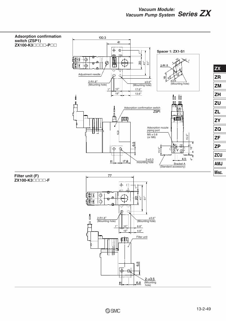
Filter unit (F)ZX100-K3����-F
Adsorption confirmation switch (ZSP1)ZX100-K3����-P��
Spacer 1: ZX1-S1
Adjustment needle
2-R1.8∗(Mounting hole)
1∗ 10∗
19∗17.6∗
13.6∗
ø3.6∗(Mounting hole)
41∗
1∗∗
51∗
ø3.6(Mounting hole)
Adsorption confirmation switch
Adsorption nozzlepiping port
M5 x 0.8(or M6)
2-ø3.3mounting hole Bracket A
(Standard accessory)
18∗∗
15.5
∗
15.5
∗
4∗
2-R1.8∗(Mounting hole)
ø3.6∗(Mounting hole)
41∗
1∗∗
51∗
1∗ 10∗
19∗8.8∗
4.8∗
Filter unit
(Mounting hole)
Series ZX
13-2-49
Vacuum Module:Vacuum Pump System
ZX
ZR
ZM
ZH
ZU
ZL
ZY
ZQ
ZF
ZP
ZCU
AMJ
Misc.
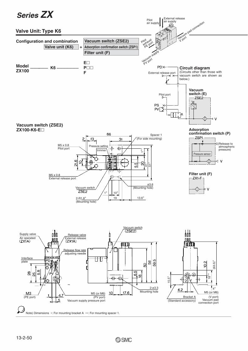
Valve Unit: Type K6
Vacuum switch (ZSE2)ZX100-K6-E�
Note) Dimensions ∗: For mounting bracket A ∗∗: For mounting spacer 1.
Vacuum switch (E)
Adsorption confirmation switch (P)
Filter unit (F)
Configuration and combination Valve unit (K6) +
ModelZX100
—————— K6 ———————
Vacuum switch (ZSE2)Adsorption confirmation switch (ZSP1)
Filter unit (F)
E�P��F
Circuit diagram(Circuits other than those with vacuum switch are shown as below.)
Pilotair supply
External releaseair supply
Pilot
exhaust
PE port
Vacuum supply
PV port
Vacuum pad connection
V port
External release port
Pilot port
(Release to atmospheric pressure)
Pressure sensor
Pressure setting trimmer
M5 x 0.8Pilot port
M5 x 0.8External release port
Spacer 1(For side mounting)
41∗
1∗∗
51∗
2-R1.8∗(Mounting hole)
Vacuum switch
1∗ 10∗
19 13.6∗
ø3.6(Mounting hole)
Supply valveAir operated
Release valveExternal release
Release flow rateadjusting needle
Interfaceplate
(PE port)M5 (or M6)
(PV port)Vacuum supply pressure port
Vacuum switch
2-ø3.3Mounting hole
Bracket A(Standard accessory)
M5 (or M6)
(V port)Vacuum pad
connection port
4∗
15.5
∗
18∗∗
(63.
5)∗
Series ZX
13-2-50

Filter unit (F)ZX100-K6-F
Adsorption confirmation switch (ZSP1)ZX100-K6-P��
Spacer 1: ZX1-S1Adjusting needle
2-R1.8∗(Mounting hole)
1∗ 10∗
19∗17.8∗
ø3.6∗(Mounting hole)
41∗
20∗
1∗∗
51∗
ø3.6(Mounting hole)
Adsorption confirmation switch
2-ø3.3Mounting hole
Adsorption nozzlepiping portM5 x 0.8(or M6 x 1)
Bracket A(Standard accessory)
4∗
(63.
5)∗
15.5
∗
18∗∗
2-R1.8∗(Mounting hole)
1∗ 10∗
19∗8.8∗
4.8∗
ø3.6∗(Mounting hole)
Filter unit
(Mounting hole)
1∗∗
41∗
51∗
Series ZX
13-2-51
Vacuum Module:Vacuum Pump System
ZX
ZR
ZM
ZH
ZU
ZL
ZY
ZQ
ZF
ZP
ZCU
AMJ
Misc.

Valve Unit: Type K8
Vacuum switch (ZSE2)ZX100-K8-E�
Note) Dimensions ∗: For mounting bracket A ∗∗: For mounting spacer 1.
Vacuum switch (E)
Adsorption confirmation switch (P)
Filter unit (F)
Configuration and combination Valve unit (K8) +
ModelZX100 ———————— K8 ————————
Vacuum switch (ZSE2)Adsorption confirmation switch (ZSP1)Filter unit (F)
E�P��F
Circuit diagram(Circuits other than those with vacuum switch are shown as below.)
Air supplyfor supplyvalve pilot
Air supplyfor releasevalve pilot
Pilot
exhaust
PE port
Vacuum switch va
lve
air supply
PS port
Vacuum
supply
PV port
Vacuum pad connection
V port
Pilot port
Pilot port
Pressure sensor
(Release to atmospheric pressure)
(Pilot port for supply valve)
M3 x 0.5
(Pilot port for release valve)
M3 x 0.5
Pressure settingtrimmer
Spacer 1(For side mounting)
2-R1.8∗(Mounting hole)
1∗ 10∗
19∗7.6∗
13.6∗
ø3.6∗(Mounting hole)
41∗
1∗∗
51∗
Supply valve N.O.(Air operated VJA324)
Release valve(Air operated
VJA314)Manual override(Non-locking) Release flow rate
adjusting needle
Interfaceplate (PS port)
Air supply portfor vacuum switch
valve
(PE port) M5 (or M6)(PV port)
Vacuum supply pressure port
Vacuum switch
2-ø3.3Mounting hole
Bracket A(Standard accessory)
M5 (or M6)(V port)
Vacuum padconnection port
18∗∗
63.5
∗4∗
15.5
∗
Series ZX
13-2-52
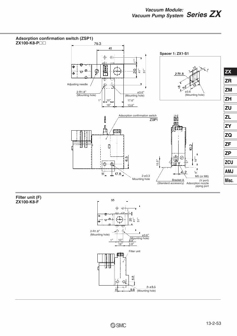
Filter unit (F)ZX100-K8-F
Adsorption confirmation switch (ZSP1)ZX100-K8-P��
Spacer 1: ZX1-S1
Adjusting needle
2-R1.8∗(Mounting hole)
1∗ 10∗
19∗17.6∗
13.6∗
ø3.6∗(Mounting hole)
41∗
1∗∗
51∗
ø3.6(Mounting hole)
Adsorption confirmation switch
2-ø3.3Mounting hole Bracket A
(Standard accessory)
M5 (or M6)
(V port)Adsorption nozzle
piping port
15.5
∗
18∗∗
4∗
2-R1.8∗(Mounting hole) ø3.6∗
(Mounting hole)8.8∗4.8∗
1∗ 10∗
19∗
41∗
1∗∗
51∗
Filter unit
(Mounting hole)
Series ZX
13-2-53
Vacuum Module:Vacuum Pump System
ZX
ZR
ZM
ZH
ZU
ZL
ZY
ZQ
ZF
ZP
ZCU
AMJ
Misc.
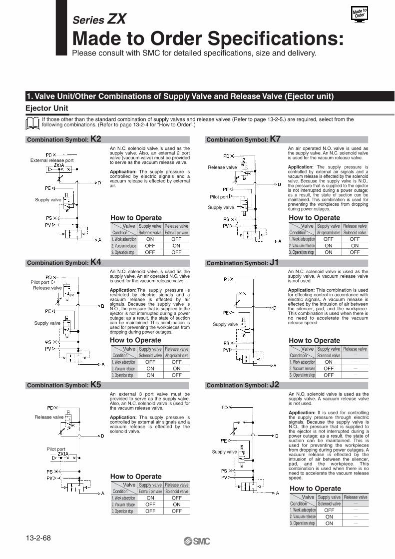
Combination Symbol: K2
How to Operate
Combination Symbol: K7
How to Operate
An N.C. solenoid valve is used as the supply valve. Also, an external 2 port valve (vacuum valve) must be provided to serve as the vacuum release valve.
Application: The supply pressure is controlled by electric signals and a vacuum release is effected by external air.
An air operated N.O. valve is used as the supply valve. An N.C. solenoid valve is used for the vacuum release valve.
Application: The supply pressure is controlled by external air signals and a vacuum release is effected by the solenoid valve. Because the supply valve is N.O., the pressure that is supplied to the ejector is not interrupted during a power outage; as a result, the state of suction can be maintained. This combination is used for preventing the workpieces from dropping during power outages.
If those other than the standard combination of supply valves and release valves (Refer to page 13-2-5.) are required, select from the following combinations. (Refer to page 13-2-4 for “How to Order”.)
Valve Supply valve Release valveSolenoid valve External 2 port valve
ON OFFOFF ONOFF OFF
Condition1. Work adsorption2. Vacuum release3. Operation stop
Valve Supply valve Release valveAir operated valve Solenoid valve
OFF OFFON ONON OFF
Condition1. Work adsorption2. Vacuum release3. Operation stop
Combination Symbol: K4
How to Operate
Combination Symbol: J1
How to Operate
An N.O. solenoid valve is used as the supply valve. An air operated N.C. valve is used for the vacuum release valve.
Application: The supply pressure is restricted by electric signals and a vacuum release is effected by air signals. Because the supply valve is N.O., the pressure that is supplied to the ejector is not interrupted during a power outage; as a result, the state of suction can be maintained. This combination is used for preventing the workpieces from dropping during power outages.
An N.C. solenoid valve is used as the supply valve. A vacuum release valve is not used.
Application: This combination is used for effecting control in accordance with electric signals. A vacuum release is effected by the intrusion of air between the silencer, pad, and the workpiece. This combination is used when there is no need to accelerate the vacuum release speed.
Combination Symbol: K5
How to Operate
Combination Symbol: J2
How to Operate
An external 3 port valve must be provided to serve as the supply valve. Also, an N.C. solenoid valve is used for the vacuum release valve.
Application: The supply pressure is controlled by external air signals and a vacuum release is effected by the solenoid valve.
An N.O. solenoid valve is used as the supply valve. A vacuum release valve is not used.
Application: It is used for controlling the supply pressure through electric signals. Because the supply valve is N.O., the pressure that is supplied to the ejector is not interrupted during a power outage; as a result, the state of suction can be maintained. This is used for preventing the workpieces from dropping during power outages. A vacuum release is effected by the intrusion of air between the silencer, pad, and the workpiece. This combination is used when there is no need to accelerate the vacuum release speed.
Valve Supply valve Release valveSolenoid valve Air operated valve
OFF OFFON ONON OFF
Condition1. Work adsorption2. Vacuum release3. Operation stop
Valve Supply valve Release valveSolenoid valve
ONOFFOFF
Condition1. Work adsorption2. Vacuum release3. Operation stop
Valve Supply valve Release valveSolenoid valve
OFFONON
Condition1. Work adsorption2. Vacuum release3. Operation stop
Valve Supply valve Release valveExternal 3 port valve Solenoid valve
ON OFFOFF ONOFF OFF
Condition1. Work adsorption2. Vacuum release3. Operation stop
1. Valve Unit/Other Combinations of Supply Valve and Release Valve (Ejector unit)Ejector Unit
External release port
Supply valve
Supply valve
Supply valveSupply valve
Supply valve
Release valve
Pilot port
Pilot portRelease valve
Release valve
Pilot port
Series ZX Made to Order Specifications:Please consult with SMC for detailed specifications, size and delivery.
13-2-68

Combination Symbol: J3 Combination Symbol: D2
Combination Symbol: J4 Combination Symbol: D3
Combination Symbol: D1 Combination Symbol: D4
How to Operate How to Operate
An N.C. solenoid valve is used as the supply valve. A vacuum release valve is not used.
Application: The supply pressure is controlled by external air signals. A vacuum release is effected by the intrusion of air between the silencer, pad, and the workpiece. This is used when there is no need to accelerate the vacuum release speed.
An N.C. solenoid valve is used for the vacuum release valve. An external supply valve must be provided.
Application: The supply pressure is controlled by the external valve and a vacuum release is effected by the solenoid valve.
How to Operate How to Operate
An air operated N.O. valve is used as the supply valve. A vacuum release valve is not used.
Application: The supply pressure is controlled by external air signals. Because the supply valve is N.O., the pressure that is supplied to the ejector is not interrupted during a power outage; as a result, the state of suction can be maintained. This is used for preventing the workpieces from dropping during power outages. A vacuum release is effected by the intrusion of air between the silencer, pad, and the workpiece. This type is used when there is no need to accelerate the vacuum release speed.
An external valve must be provided to serve as the supply valve. Also, an external 2 port valve (vacuum valve) must be provided to serve as the vacuum release valve.
Application: The supply pressure is controlled by the external valve and a vacuum release is effected by the external 2 port valve (vacuum valve).
How to Operate How to Operate
An N.C. solenoid valve is used for the vacuum release valve. An external supply valve must be provided.
Application: The supply pressure is controlled by the external valve and a vacuum release is effected by the solenoid valve.
An external valve must be provided to serve as the supply valve. An air operated N.C. valve is used for the vacuum release valve.
Application: The supply pressure is controlled by the external valve and a vacuum release is effected by external air signals.
Valve Supply valve Release valveExternal 3 port valve
ONOFFOFF
Condition1. Work adsorption2. Vacuum release3. Operation stop
Valve Supply valve Release valveExternal valve Solenoid valve
ON OFFOFF ONOFF OFF
Condition1. Work adsorption2. Vacuum release3. Operation stop
Valve Supply valve Release valveAir operated valve
OFFONOFF
Condition1. Work adsorption2. Vacuum release3. Operation stop
Valve Supply valve Release valveExternal valve Solenoid valve
ON OFFOFF ONOFF OFF
Condition1. Work adsorption2. Vacuum release3. Operation stop
Valve Supply valve Release valveExternal valve Solenoid valve
ON OFFOFF ONOFF OFF
Condition1. Work adsorption2. Vacuum release3. Operation stop
Valve Supply valve Release valveExternal valve Air operated valve
ONOFFOFF
OFFONOFF
Condition1. Work adsorption2. Vacuum release3. Operation stop
Pilot port
Release valve
Pilot port
Release valvePilot portRelease valve
External release port
Series ZX Made to Order Specifications:Please consult with SMC for detailed specifications, size and delivery.
13-2-69
ZX
ZR
ZM
ZH
ZU
ZL
ZY
ZQ
ZF
ZP
ZCU
AMJ
Misc.

Combination Symbol: K2 Combination Symbol: K7
If those other than the standard combination of supply valves (Refer to page 13-2-41.) and release valves are required, select from the following combinations. (Refer to page 13-2-40 for “How to Order”.)
Combination Symbol: K4 Combination Symbol: J1
Combination Symbol: K5 Combination Symbol: J2
1. Valve Unit/Other Combinations of Supply Valve and Release Valve (Vacuum pump system)
Vacuum Pump System
How to Operate How to Operate
An N.C. solenoid valve is used as the supply valve. Also, an external 2 port valve (vacuum valve) must be provided to serve as the vacuum release valve.
Application: The supply pressure is controlled by electric signals and a vacuum release is effected by external air.
An air operated N.O. valve is used as the supply valve. An N.C. solenoid valve is used for the vacuum release valve.
Application: The supply pressure is controlled by external air signals and a vacuum release is effected by the solenoid valve. Because the supply valve is the N.O., the pressure that is supplied to the ejector is not interrupted during a power outage; as a result, the state of suction can be maintained. This combination is used for preventing the workpieces from dropping during power outages.
How to Operate How to Operate
An N.O. solenoid valve is used as the supply valve. An air operated N.C. valve is used for the vacuum release valve.
Application: The supply pressure is controlled by electric signals and a vacuum release is effected by air signals. Because the supply valve is N.O., the pressure that is supplied to the ejector is not interrupted during a power outage; as a result, the state of suction can be maintained. This combination is used for preventing the workpieces from dropping during power outages.
An N.C. solenoid valve is used as the supply valve. A vacuum release valve is not used.
Application: This combination is used for controlling the pressure by electric signals. Normally, the workpiece is released due to the air leakage that occurs between the pad and the workpiece. However, if there is no air leakage, the workpiece will not become detached because the vacuum state is maintained even when the supply valve is turned OFF. To effect releasing, an external 2 port valve (vacuum valve) must be provided.
How to Operate How to Operate
An external 3 port valve must be provided to serve as the supply valve. Also, an N.C. solenoid valve is used for the vacuum release valve.
Application: The supply pressure is controlled by external air signals and a vacuum release is effected by the solenoid valve.
An N.O. solenoid valve is used as the supply valve. A vacuum release valve is not used.
Application: Used for controlling with electric signals. Because the supply N.O., the pressure is not interrupted during a power outage. This prevents the workpieces from dropping. Normally, the workpiece is released due to leakage. However, if no air leakage, the workpiece will not detach because the vacuum state is maintained even when the supply valve is turned ON. To release, an external 2 port valve (vacuum valve) must be used.
Valve Supply valve Release valveSolenoid valve External 2 port valve
ON OFFOFF ONOFF OFF
Condition1. Work adsorption2. Vacuum release3. Operation stop
Valve Supply valve Release valveAir operated valve Solenoid valve
OFF OFFON ONON OFF
Condition1. Work adsorption2. Vacuum release3. Operation stop
Valve Supply valve Release valveSolenoid valve Solenoid valve
OFF OFFON ONON ON
Condition1. Work adsorption2. Vacuum release3. Operation stop
Valve Supply valve Release valveSolenoid valve
ONOFFOFF
Condition1. Work adsorption2. Vacuum release3. Operation stop
Valve Supply valve Release valveExternal 3 port valve Solenoid valve
ON OFFOFF ONOFF OFF
Condition1. Work adsorption2. Vacuum release3. Operation stop
Valve Supply valve Release valveSolenoid valve
OFFONON
Condition1. Work adsorption2. Vacuum release3. Operation stop
External release port
Supply valve Supply valve
Supply valveSupply valve
Supply valve
Release valve
Release valve
Release valve
Pilot port
Pilot port
Pilot port
Series ZX Made to Order Specifications:Please consult with SMC for detailed specifications, size and delivery.
13-2-70
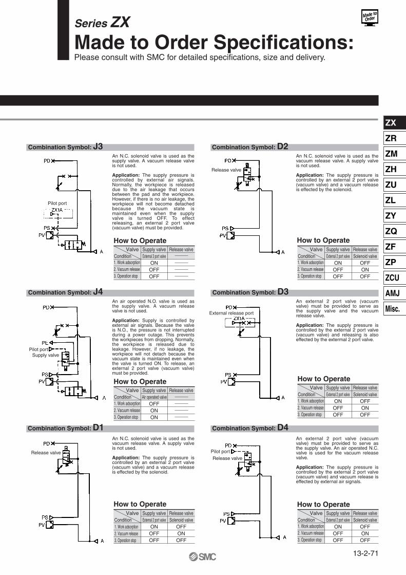
Combination Symbol: J3 Combination Symbol: D2
Combination Symbol: J4 Combination Symbol: D3
Combination Symbol: D1 Combination Symbol: D4
How to Operate How to Operate
An N.C. solenoid valve is used as the supply valve. A vacuum release valve is not used.
Application: The supply pressure is controlled by external air signals. Normally, the workpiece is released due to the air leakage that occurs between the pad and the workpiece. However, if there is no air leakage, the workpiece will not become detached because the vacuum state is maintained even when the supply valve is turned OFF. To effect releasing, an external 2 port valve (vacuum valve) must be provided.
An N.C. solenoid valve is used as the vacuum release valve. A supply valve is not used.
Application: The supply pressure is controlled by an external 2 port valve (vacuum valve) and a vacuum release is effected by the solenoid.
How to Operate How to Operate
An air operated N.O. valve is used as the supply valve. A vacuum release valve is not used.
Application: Supply is controlled by external air signals. Because the valve is N.O., the pressure is not interrupted during a power outage. This prevents the workpieces from dropping. Normally, the workpiece is released due to leakage. However, if no leakage, the workpiece will not detach because the vacuum state is maintained even when the valve is turned ON. To release, an external 2 port valve (vacuum valve) must be provided.
An external 2 port valve (vacuum valve) must be provided to serve as the supply valve and the vacuum release valve.
Application: The supply pressure is controlled by the external 2 port valve (vacuum valve) and releasing is also effected by the extermal 2 port valve.
How to Operate How to Operate
An N.C. solenoid valve is used as the vacuum release valve. A supply valve is not used.
Application: The supply pressure is controlled by an external 2 port valve (vacuum valve) and a vacuum release is effected by the solenoid.
An external 2 port valve (vacuum valve) must be provided to serve as the supply valve. An air operated N.C. valve is used for the vacuum release valve.
Application: The supply pressure is controlled by the external 2 port valve (vacuum valve) and vacuum release is effected by external air signals.
Valve Supply valve Release valveExternal 3 port valve
ONOFFOFF
Condition1. Work adsorption2. Vacuum release3. Operation stop
Valve Supply valve Release valveExternal 2 port valve Solenoid valve
ON OFFOFF ONOFF OFF
Condition1. Work adsorption2. Vacuum release3. Operation stop
Valve Supply valve Release valveAir operated valve
OFFONON
Condition1. Work adsorption2. Vacuum release3. Operation stop
Valve Supply valve Release valveExternal 2 port valve Solenoid valve
ON OFFOFF ONOFF OFF
Condition1. Work adsorption2. Vacuum release3. Operation stop
Valve Supply valve Release valveExternal 2 port valve Solenoid valve
ON OFFOFF ONOFF OFF
Condition1. Work adsorption2. Vacuum release3. Operation stop
Valve Supply valve Release valveExternal 2 port valve Solenoid valve
ON OFFOFF ONOFF OFF
Condition1. Work adsorption2. Vacuum release3. Operation stop
Pilot port
Pilot port
Pilot portRelease valve
Release valve
Release valve
Supply valve
External release port
Series ZX Made to Order Specifications:Please consult with SMC for detailed specifications, size and delivery.
13-2-71
ZX
ZR
ZM
ZH
ZU
ZL
ZY
ZQ
ZF
ZP
ZCU
AMJ
Misc.

Series ZX Made to Order Specifications:Please consult SMC for detailed specifications, size and delivery.
Reduction in the exhaust noise from the ejector (Silencing effect 8 dB (A) Standard silencer assembly comparison)
Nozzle diameter Exhaust style Electrical entryVoltage –X121
Noise reduction silencer assembly
ZX1 Valve
Noise reductionsilencer assembly
ZX1-HS1
Ordering example
Noise reductionsilencer assembyZX1-HS1
Ordering example∗
Phillips screw (M2 x 23)P3270147-23
Noise absorbing material G
Silencer case F
Silencer case ENoise reductionsilencer assemblyZX1-HS1
1 pc.2 pcs.
1. Noise Reduction Silencer Assembly/The ejector exhaust style is applicable to the silencer equipped specifications.
P3200223-2
P3200224-1
P3200225
ZX1101-K35LZ-D23C-X121
ZZX102-RZX1101-K35LZ-EC-X121
13-2-72