Embed Size (px)
Citation preview
User'sManual
Messages
IM 32Q02B10-31E
IM 32Q02B10-31E4th Edition
IntroductionThis manual describes the details of Diagnostic Information messages displayed in the Diag-nostic Information Window of SCS Maintenance Support Tool or System Alarm View of HIS.The table of the contents of this manual can be used as message number index.This manual consists of the following chapters:
Chapter 1 : This chapter explains how to refer to the Diagnosis Information in SENG.Chapter 2 : This chapter explains the details about SCS Messages.Chapter 3 : This chapter explains the details about common messages of CENTUM VP or
CS 3000 and SENG.Appendix : A list of the alarm class for the corresponding message number is provided.
i
Media No. IM 32Q02B10-31E (CD) 4th Edition : Jan. 2015 (YK)All Rights Reserved Copyright © 2011, Yokogawa Electric Corporation
IM 32Q02B10-31E 4th Edition : Jan.30,2015-00
Safety Precautions for Usen Safety, Protection, and Modification of the Product
• To protect the system controlled by the Product and the Product itself and to ensure safeoperation, please observe the safety precautions described in this Manual. YokogawaElectric Corporation ("YOKOGAWA") assumes no liability for safety if users fail to observethe safety precautions and instructions when operating the Product.
• If the Product is used in a manner not specified in the User's Manuals, the protection pro-vided by the Product may be impaired.
• If any protection or safety circuit is required for the system controlled by the Product or forthe Product itself, please install it externally.
• Use only spare parts that are approved by YOKOGAWA when replacing parts or consum-ables of the Product.
• Do not use the Product and its accessories such as power cords on devices that are notapproved by YOKOGAWA. Do not use the Product and its accessories for any purposeother than those intended by YOKOGAWA.
• Modification of the Product is strictly prohibited.
• The following symbols are used in the Product and User's Manuals to indicate the accom-panying safety precautions:
Indicates that caution is required for operation. This symbol is labeled on the Prod-uct to refer the user to the User's Manuals for necessary actions or behaviors inorder to protect the operator and the equipment against dangers such as electricshock. In the User's Manuals, you will find the precautions necessary to preventphysical injury or death, which may be caused by accidents, such as electricshock resulting from operational mistakes.Identifies a protective conductor terminal. Before using the Product, you mustground the protective conductor terminal to avoid electric shock.Identifies a functional grounding terminal. A terminal marked "FG" also has thesame function. This terminal is used for grounding other than protective grounding.Before using the Product, you must ground this terminal.Indicates an AC supply.
Indicates a DC supply.Indicates the ON position of a power on/off switch.
Indicates the OFF position of a power on/off switch.
n Notes on Handling User's Manuals• Hand over the User's Manuals to your end users so that they can keep the User's Man-
uals on hand for convenient reference.
• Thoroughly read and understand the information in the User's Manuals before using theProduct.
• For the avoidance of doubt, the purpose of the User's Manuals is not to warrant that theProduct is suitable for any particular purpose but to describe the functional details of theProduct.
• Contents of the User's Manuals are subject to change without notice.
ii
IM 32Q02B10-31E 4th Edition : Jan.30,2015-00
• Every effort has been made to ensure the accuracy of contents in the User's Manuals.However, should you have any questions or find any errors, contact us or your local dis-tributor. The User's Manuals with unordered or missing pages will be replaced.
n Warning and Disclaimer• Except as specified in the warranty terms, YOKOGAWA shall not provide any warranty for
the Product.
• YOKOGAWA shall not be liable for any indirect or consequential loss incurred by eitherusing or not being able to use the Product.
n Notes on Software• YOKOGAWA makes no warranties, either expressed or implied, with respect to the Soft-
ware Product's merchantability or suitability for any particular purpose, except as speci-fied in the warranty terms.
• Purchase the appropriate number of licenses of the Software Product according to thenumber of computers to be used.
• No copy of the Software Product may be made for any purpose other than backup; other-wise, it is deemed as an infringement of YOKOGAWA's Intellectual Property rights.
• Keep the software medium of the Software Product in a safe place.
• No reverse engineering, reverse compiling, reverse assembling, or converting the Soft-ware Product to human-readable format may be performed for the Software Product.
• No part of the Software Product may be transferred, converted, or sublet for use by anythird-party, without prior written consent from YOKOGAWA.
iii
IM 32Q02B10-31E 4th Edition : Jan.30,2015-00

Documentation Conventionsn Symbols
The following symbols are used in the User's Manuals.
Identifies instructions that must be observed to avoid physicalinjury, electric shock, or death.
Identifies instructions that must be observed to prevent damageto the software or hardware, or system failures of the Product.
Identifies important information required to understand opera-tions or functions.
Identifies additional information.
Identifies referenced content.In online manuals, you can view the referenced content by click-ing the links that are in green text. However, this action does notapply to the links that are in black text.
n Typographical ConventionsThe following typographical conventions are used throughout the User's Manuals.
l Commonly Used Conventions throughout the User's Manuals• Δ Mark
Indicates that a space must be entered between character strings.Example:
.ALΔPIC010Δ-SC• Character string enclosed by braces { }
Indicates character strings that may be omitted.Example:
.PRΔTAG{Δ.sheet name}
l Conventions Used to Show Key or Button Operations• Characters enclosed by brackets [ ]
When characters are enclosed by brackets in the description of a key or button operation,it indicates a key on the keyboard, a button name in a window, or an item in a list boxdisplayed in a window.Example:
To alter the function, press the [ESC] key.
l Conventions of a User-defined Folder• User-defined folder name enclosed by parenthesis ( )
User definable path is written in a pair of parentheses.Example:
iv
IM 32Q02B10-31E 4th Edition : Jan.30,2015-00
(RS Project Folder)\SCS0101 If the RS Project Folder is C:\MYRSPJT, the above path becomes C:\MYRSPJTSCS0101.
n Drawing ConventionsDrawings used in the User's Manuals may be partially emphasized, simplified, or omitted forthe convenience of description.Drawings of windows may be slightly different from the actual screenshots with different set-tings or fonts. The difference does not hamper the understanding of basic functionalities andoperation and monitoring tasks.
n Integration with CENTUMThe Product can be integrated with CENTUM VP or CENTUM CS 3000. In the User's Man-uals, the integration with CENTUM VP or CENTUM CS 3000 is referred to as "Integration withCENTUM."In the User's Manuals, the explanations for integrating the Product with CENTUM VP orCENTUM CS 3000, the glossary for various features of CENTUM VP is used instead of theglossary for CENTUM CS 3000. For example, the term "CENTUM VP System Alarm View" isused instead of "CENTUM CS 3000 System Alarm window." Nevertheless, if the features forintegrating the Product with CENTUM VP and CENTUM CS 3000 are different, both featureswill be explained separately.
SEEALSO For more information about the functions and usage of CENTUM VP components for integrating the Product
with CENTUM VP, refer to:
User's Manuals (IM), Technical Information (TI), and General Specifications (GS) of CENTUM VP
For more information about the features and usage of CENTUM CS 3000 components for integrating theProduct with CENTUM CS 3000, refer to:
User's Manuals (IM), Technical Information (TI), and General Specifications (GS) of CENTUM CS 3000
n Explanation of Hardware and Software Behaviors in the User'sManuals
In the User's Manuals, system behaviors are explained assuming that the latest versions ofYOKOGAWA software and hardware at the time of publication of the User's Manuals are in-stalled.If additional precise information about the safety of legacy versions of software or hardware isrequired, a link to the corresponding explanation is provided. Please refer to the informationaccording to your system.
n Station TypesA safety control station (hereafter referred to as SCS) is named according to the type of thesafety control unit used in it.
Table Info-1 Names of SCS and Safety Control Unit UsedName of SCS Model of the safety control unit
SCSV1-S SSC10S/SSC10D
SCSP1-S SSC50S/SSC50D
SCSP2-S SSC60S/SSC60D
SCSU1-S SSC57S/SSC57D
v
IM 32Q02B10-31E 4th Edition : Jan.30,2015-00

In the User's Manuals, the following abbreviations may be used to describe functions of theseSCS as a whole.• SCSV1: Abbreviation of SCSV1-S
• SCSP1: Abbreviation of SCSP1-S
• SCSP2: Abbreviation of SCSP2-S
• SCSU1: Abbreviation of SCSU1-S
vi
IM 32Q02B10-31E 4th Edition : Jan.30,2015-00
Copyright and Trademark Noticesn All Rights Reserved
The copyright of the programs and online manuals contained in the software medium of theSoftware Product shall remain with YOKOGAWA.You are allowed to print the required pages of the online manuals for the purposes of using oroperating the Product; however, reprinting or reproducing the entire document is strictly pro-hibited by the Copyright Law.Except as stated above, no part of the online manuals may be reproduced, transferred, sold,or distributed to a third party in any manner (either in electronic or written form including, with-out limitation, in the forms of paper documents, electronic media, and transmission via thenetwork). Nor it may be registered or recorded in the media such as films without permission.
n Trademark Acknowledgments• CENTUM, ProSafe, Vnet/IP, and STARDOM are registered trademarks of YOKOGAWA.
• Microsoft, Windows, Windows Vista, Windows Server, Visual Basic, Visual C++, and Vis-ual Studio are either registered trademarks or trademarks of Microsoft Corporation in theUnited States and other countries.
• Adobe, Acrobat, and Adobe Reader are registered trademarks of Adobe Systems Incor-porated.
• Ethernet is a registered trademark of Xerox Corporation.
• HART is a registered trademark of the HART Communication Foundation.
• Modicon and Modbus are registered trademarks of Schneider Electric SA.
• All other company and product names mentioned in the User's Manuals are trademarksor registered trademarks of their respective companies.
• TM or ® mark are not used to indicate trademarks or registered trademarks in the User'sManuals.
• Logos and logo marks are not used in the User's Manuals.
vii
IM 32Q02B10-31E 4th Edition : Jan.30,2015-00
Messages
IM 32Q02B10-31E 4th Edition
CONTENTS1. Referencing Diagnostic Information Messages on the SENG......... 1-1
1.1 How to Display the Diagnostic Information Window.................................1-21.2 Diagnostic Information Window..................................................................1-31.3 Printout of Diagnostic Information Message............................................. 1-4
2. Details of Output Messages Specific to the SCS.............................. 2-12.1 System Alarms (Message Numbers 4101 through 4199).......................... 2-2
No. 4101 Inter-SCS safety communication error information ....................... 2-2
No. 4102 Inter-SCS safety communication error recovery information .........2-3
No. 4103 Variable lock .................................................................................. 2-3
No. 4104 Cancellation of variable lock ..........................................................2-4
No. 4105 I/O module lock ............................................................................. 2-4
No. 4106 Cancellation of I/O module lock .....................................................2-5
No. 4107 All input module locks ....................................................................2-5
No. 4108 Cancellation of all input module locks ........................................... 2-5
No. 4109 All output module locks ................................................................. 2-5
No. 4110 Cancellation of all output module locks ......................................... 2-5
No. 4111 All module locks ............................................................................ 2-5
No. 4112 Cancellation of all module locks .................................................... 2-6
No. 4113 Number of locks exceeded ............................................................2-6
No. 4114 Recovery from exceeded number of locks .................................... 2-6
No. 4115 Override setting ............................................................................. 2-6
No. 4116 Cancellation of override .................................................................2-6
No. 4117 Information of change to override enabled state ........................... 2-7
No. 4118 Information of change to override disabled state .......................... 2-7
No. 4119 Number of overrides exceeded ..................................................... 2-7
No. 4120 Recovery from exceeded number of overrides ............................. 2-7
No. 4121 Number of enabled overrides exceeded ....................................... 2-8
No. 4122 Recovery from exceeded number of enabled overrides ................2-8
No. 4123 Number of active PASSWD FBs exceeded ...................................2-8
No. 4124 Recovery from exceeded number of active PASSWD FBs ........... 2-8
No. 4125 I/O module channel error occurred ................................................2-9
No. 4126 Recovery from I/O module channel error ...................................... 2-9
No. 4127 Setting PASSWD FB to ON ...........................................................2-9
Toc-1
IM 32Q02B10-31E 4th Edition : Jan.30,2015-00
No. 4128 Setting PASSWD FB to OFF ......................................................... 2-9
No. 4129 GPS interface unit error ...............................................................2-10
No. 4130 Recovery of GPS interface unit ................................................... 2-10
No. 4131 Communication module lock ....................................................... 2-10
No. 4132 Cancellation of Communication module lock .............................. 2-10
No. 4133 Information of a diagnosis error in the received data of SCS LinkTransmission. .............................................................................. 2-11
No. 4134 Information of a diagnosis error recovery in the received data ofSCS Link Transmission. .............................................................. 2-12
No. 4135 SCS Link Transmission data lock ................................................2-12
No. 4136 Cancellation of SCS Link Transmission data lock ....................... 2-13
No. 4137 Number of Locked Stations in SCS Link Transmission Exceeded .......................................................................................................... 2-13
No. 4138 Recovery from exceeded number of locked stations in SCS LinkTransmission ............................................................................... 2-13
No. 4139 Inter-SCS Safety Communication data lock ................................ 2-13
No. 4140 Cancellation of Inter-SCS Safety Communication data lock ....... 2-14
No. 4141 Number of locked stations in Inter-SCS Safety Communicationexceeded .....................................................................................2-14
No. 4142 Recovery from exceeded number of locked stations in Inter-SCSSafety Communication ................................................................ 2-14
No. 4143 Start of automatic scan period extension .................................... 2-14
No. 4144 Cancellation of automatic scan period extension ........................ 2-15
No. 4145 Abnormal calculation occurred .................................................... 2-15
No. 4146 Recovery from abnormal calculation ........................................... 2-15
No. 4151 Information of retainable data initialization .................................. 2-16
No. 4152 Online change of scan period ......................................................2-16
No. 4153 Information of Inter-SCS Safety Communication data lock time-up ........................................................................................................ 2-16
No. 4154 Information of forced cancellation of Inter-SCS SafetyCommunication data locks .......................................................... 2-16
No. 4155 Information of SCS Link Transmission status change. ................2-17
No. 4156 Information of SCS Link Transmission definition change ............ 2-17
No. 4157 Information of SCS Link Transmission wiring change ................. 2-17
No. 4158 Information of SCS Link Transmission lock time-up ....................2-17
No. 4159 Information of forced cancellation of SCS Link Transmission locks ........................................................................................................ 2-17
No. 4160 Invalid password for Manual Operation FB ................................. 2-18
No. 4161 Information of Output IOM Shutdown ..........................................2-18
No. 4162 Information of communication I/O definition change ................... 2-18
No. 4163 Information of communication I/O wiring change ........................ 2-18
No. 4164 Information of disabling security level change .............................2-18
No. 4165 Information of enabling security level change ............................. 2-19
No. 4166 Information of communication module lock time-up .................... 2-19
Toc-2
IM 32Q02B10-31E 4th Edition : Jan.30,2015-00
No. 4167 Information of forced cancellation of communication module locks ........................................................................................................ 2-19
No. 4168 Information of tag name change by online change download ................................................................................................................. 2-19
No. 4169 NVRAM diagnosis error ...............................................................2-19
No. 4170 Flash memory diagnosis error .....................................................2-20
No. 4172 Information of resource change by online change download ...... 2-20
No. 4173 Completion of writing to flash memory ........................................ 2-20
No. 4174 Failed to write to flash memory ................................................... 2-21
No. 4175 Failed to update external communication data ............................2-21
No. 4177 Information of SCS security level change ................................... 2-21
No. 4178 Information of security level time-up ............................................2-22
No. 4179 Information of communication I/O module output enabled operation ...................................................................................................... 2-22
No. 4180 Information of password change ................................................. 2-22
No. 4181 Information of output enabled operation ......................................2-22
No. 4182 Information of output module start operation ...............................2-23
No. 4183 Request to upload SOE to SENG ............................................... 2-23
No. 4184 Notification on saving SOE trip signal file in SCS ....................... 2-23
No. 4185 Information of variable value change .......................................... 2-23
No. 4186 Information of lock time-up .......................................................... 2-24
No. 4187 Information of forced cancellation of locks .................................. 2-24
No. 4188 Start of online change download ................................................. 2-24
No. 4189 Completion of online change download ...................................... 2-24
No. 4190 Online change download error .................................................... 2-24
No. 4191 Completion of I/O definition rewriting .......................................... 2-25
No. 4192 Information of override state time-up ...........................................2-25
No. 4193 Information of forced release of all overrides .............................. 2-25
No. 4194 Information of override enabled state time-up .............................2-25
No. 4195 Information of communication I/O data status change ................ 2-26
No. 4196 Invalid password for PASSWD FB ...............................................2-26
No. 4197 Information on active PASSWD FB time-up ................................ 2-26
No. 4198 Information on forced reset of PASSWD FB ................................2-26
No. 4199 Override communication error .....................................................2-27
3. Details of Output Messages in Common with CENTUM................... 3-13.1 Safety Control Station Error Occurrence and Recovery Messages
(Message Numbers 0001 through 0094).....................................................3-2No. 0001 Reset start of safety control station ............................................... 3-2
No. 0003 Safety control station automatic reset start ................................... 3-2
No. 0005 Power ON initial cold start of safety control station ....................... 3-2
No. 0009 Transfer of control right of safety control station ........................... 3-2
No. 0011 Fail information of safety control station ........................................3-3
No. 0013 AC power supply failure of safety control station .......................... 3-4
Toc-3
IM 32Q02B10-31E 4th Edition : Jan.30,2015-00

No. 0015 Self-diagnosis error of clock inside CPU module .......................... 3-4
No. 0017 ROM checksum error of CPU module ...........................................3-4
No. 0021 Internal task error of safety control station .................................... 3-5
No. 0023 Mapping block fatal error ...............................................................3-5
No. 0025 Function control word error ........................................................... 3-5
No. 0027 Mapping block record information error .........................................3-5
No. 0033 Online downloading abnormal end ................................................3-5
No. 0041 Safety control station fan alarm .....................................................3-6
No. 0042 Recovery from safety control station fan alarm ............................. 3-6
No. 0043 Safety control station temperature alarm ...................................... 3-6
No. 0044 Recovery from safety control station temperature alarm ...............3-7
No. 0045 Power supply module alarm of safety control station .................... 3-7
No. 0046 Recovery from power supply module alarm of safety control station ........................................................................................................ 3-7
No. 0047 Battery alarm of CPU module ........................................................3-7
No. 0048 Recovery from battery alarm of CPU module ................................3-8
No. 0055 Information of same frame reception in online change downloadcommunication .............................................................................. 3-8
No. 0057 Information of online change download error ................................ 3-8
No. 0059 Information of recovery from node power failure ...........................3-8
No. 0063 ESB bus error ................................................................................3-8
No. 0064 Normal recovery of ESB bus ......................................................... 3-9
No. 0065 Failure of ESB Bus Interface module (SSB401) of node ...............3-9
No. 0066 Normal recovery of ESB Bus Interface module (SSB401) of node ......................................................................................................... 3-10
No. 0067 Failure of power supply module of node ..................................... 3-10
No. 0068 Normal recovery of power supply module of a node ................... 3-10
No. 0069 Error before database download to I/O module .......................... 3-10
No. 0081 Failure of I/O module ................................................................... 3-11
No. 0082 Normal recovery of I/O module ................................................... 3-13
No. 0083 I/O module database error occurred ........................................... 3-13
No. 0085 I/O module communication error occurred .................................. 3-13
No. 0086 Recovery from I/O module communication error .........................3-13
No. 0087 Node error occurred .................................................................... 3-13
No. 0088 Normal recovery of node ............................................................. 3-14
No. 0089 Subsystem communication error .................................................3-14
No. 0090 Subsystem communication recovered ........................................ 3-15
No. 0093 CPU node’s housekeeping unit error ...........................................3-15
No. 0094 Normal recovery of CPU node’s housekeeping unit ....................3-15
3.2 Safety Control Station Status Change Related Messages (MessageNumbers 0450 through 0480).................................................................... 3-16No. 0450 Copy program and database on control side of safety control station
to standby side ............................................................................ 3-16
Toc-4
IM 32Q02B10-31E 4th Edition : Jan.30,2015-00
No. 0451 Information of switching of control side of safety control station ............................................................................................................. 3-16
No. 0452 Information of switching of standby side of safety control station ............................................................................................................ 3-16
No. 0459 Information on I/O module service side .......................................3-16
No. 0460 Information of I/O module out service ......................................... 3-16
No. 0471 Normal completion of online change download ...........................3-17
No. 0474 Information of tag list duplicate error ........................................... 3-17
No. 0475 Start of database download to I/O module .................................. 3-17
No. 0476 Normal completion of database download to I/O module ............3-17
No. 0477 Database download error to I/O module ..................................... 3-17
No. 0480 Heavy load on periodical processing ...........................................3-18
3.3 Safety Control Station Related Messages (Message Numbers 0727through 0787)..............................................................................................3-19No. 0727 Block mode recovery error information ....................................... 3-19
No. 0743 Self-diagnostic SEN-BUS Failure ................................................3-19
No. 0744 Self-diagnostic SEN-BUS Recovery ............................................3-19
No. 0749 Self-diagnosis detected an I/O Error ........................................... 3-19
No. 0750 I/O Recovery from the error detected by self-diagnosis .............. 3-20
No. 0751 Time self-diagnostic testing error ................................................ 3-20
No. 0753 Communication Overload ............................................................3-20
No. 0767 Faulty one ESB bus in CPU module ........................................... 3-20
No. 0768 Single ESB bus in CPU module Recovery .................................. 3-20
No. 0787 Self-diagnosis detected I/O error in CPU module ....................... 3-21
Toc-5
IM 32Q02B10-31E 4th Edition : Jan.30,2015-00
Messages
IM 32Q02B10-31E 4th Edition
CONTENTSAppendix
Appendix 1. Alarm Class..................................................................... App.1-1
TocApp.-1
IM 32Q02B10-31E 4th Edition : Jan.30,2015-00
1. Referencing Diagnostic InformationMessages on the SENG
You can view diagnostic information messages on the Diagnostic Information window, whichis called up from SCS Status Overview window.
<1. Referencing Diagnostic Information Messages on the SENG> 1-1
IM 32Q02B10-31E 4th Edition : Jan.30,2015-00
1.1 How to Display the Diagnostic InformationWindow
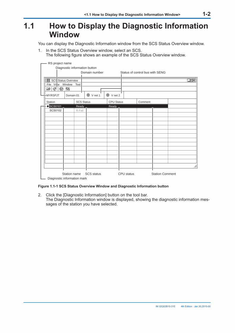
You can display the Diagnostic Information window from the SCS Status Overview window.1. In the SCS Status Overview window, select an SCS.
The following figure shows an example of the SCS Status Overview window.
SCS Status Overview File View Window Tool
MYRSPJT
Station SCS Status CPU Status Comment
Domain:01 V net 1 V net 2
Ready R-Fail
Ready
Domain number
RS project name
Status of control bus with SENG
Diagnostic information markCPU statusSCS status
Diagnostic information button
Station name Station Comment
Figure 1.1-1 SCS Status Overview Window and Diagnostic Information button
2. Click the [Diagnostic Information] button on the tool bar.The Diagnostic Information window is displayed, showing the diagnostic information mes-sages of the station you have selected.
<1.1 How to Display the Diagnostic Information Window> 1-2
IM 32Q02B10-31E 4th Edition : Jan.30,2015-00

1.2 Diagnostic Information WindowThe Diagnostic Information window is shown in the figure below.
Diagnostic Information-[SCS0101 1.3] File View Operation Help
Number Date Class Message
Number Date Class Message
4125 4125 0082 0476 0475 0082 0459 0476 0475 0047 4129 0081
5/30/2008 10:26:19.720 AM 5/30/2008 10:26:19.720 AM 5/30/2008 10:26:17.620 AM 5/30/2008 10:26:09.131 AM 5/30/2008 10:26:04.235 AM 5/30/2008 10:25:55.320 AM 5/30/2008 10:25:55.320 AM 5/30/2008 10:25:51.931 AM 5/30/2008 10:25:48.388 AM 5/30/2008 10:25:36.851 AM 5/30/2008 10:25:33.328 AM 5/30/2008 10:25:33.320 AM
1 1 3 4 4 3 4 4 4 2 2 1
SCS0101 IOM Channel Error NO. SCS0101 IOM Channel Error NO. SCS0101 IOM Recover F10 NODE SCS0101 IOM Download Complete. SCS0101 IOM Download Start F10. SCS0101 IOM Recover F10 NODE SCS0101 IOM In Service F10 NO. SCS0101 IOM Download Complete. SCS0101 IOM Download Start F10. SCS0101 LEFT Battery Alarm SCS0101 GPS Interface Unit Error SCS0101 IOM Fail FIO NODE 0.
30/95
Information
WarningAlarm marks Number of currently
generated messagesStatus bar
Toolbar Alarm classHelp button Diagnostic InformationMessage
Figure 1.2-1 Diagnostic Information Window
SEEALSO For more information about the diagnostic information window, refer to:
3.2, “Displaying SCS Diagnostic Information” in Utilities and Maintenance Reference (IM32Q04B20-31E)
n How to Display the Help Dialog BoxThe details of Diagnostic Information window is displayed in the Help dialog box.1. In the Diagnostic Information window, select a diagnostic information message.
2. Click the [Help] button on the tool bar.The Help dialog box is displayed.
SEEALSO For more information about the Help dialog box, refer to:
3.2.3, “Diagnostic Information Message Help Function” in Utilities and Maintenance Reference (IM32Q04B20-31E)
<1.2 Diagnostic Information Window> 1-3
IM 32Q02B10-31E 4th Edition : Jan.30,2015-00
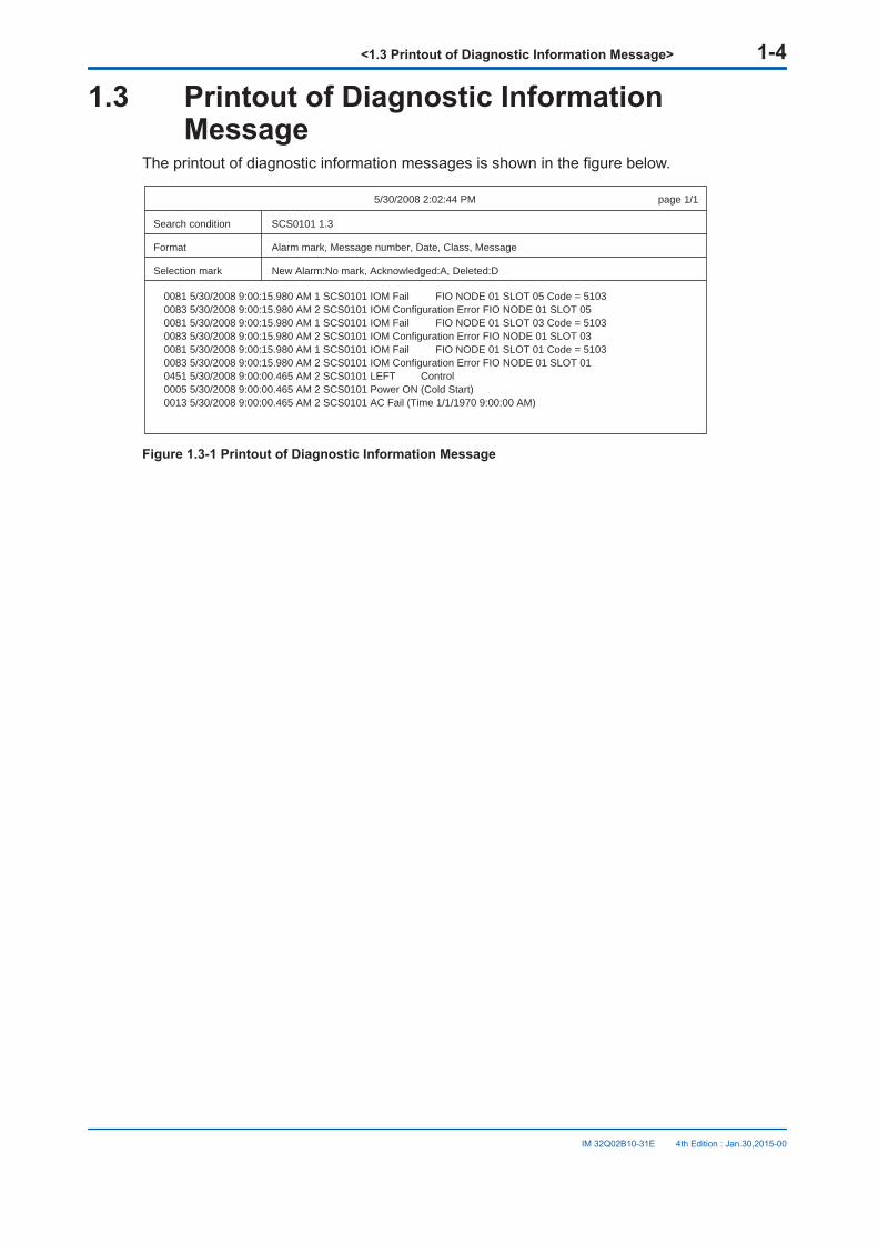
1.3 Printout of Diagnostic InformationMessage
The printout of diagnostic information messages is shown in the figure below.
5/30/2008 2:02:44 PM
Search condition SCS0101 1.3
Format Alarm mark, Message number, Date, Class, Message
Selection mark New Alarm:No mark, Acknowledged:A, Deleted:D
0081 5/30/2008 9:00:15.980 AM 1 SCS0101 IOM Fail FIO NODE 01 SLOT 05 Code = 51030083 5/30/2008 9:00:15.980 AM 2 SCS0101 IOM Configuration Error FIO NODE 01 SLOT 050081 5/30/2008 9:00:15.980 AM 1 SCS0101 IOM Fail FIO NODE 01 SLOT 03 Code = 51030083 5/30/2008 9:00:15.980 AM 2 SCS0101 IOM Configuration Error FIO NODE 01 SLOT 030081 5/30/2008 9:00:15.980 AM 1 SCS0101 IOM Fail FIO NODE 01 SLOT 01 Code = 51030083 5/30/2008 9:00:15.980 AM 2 SCS0101 IOM Configuration Error FIO NODE 01 SLOT 010451 5/30/2008 9:00:00.465 AM 2 SCS0101 LEFT Control0005 5/30/2008 9:00:00.465 AM 2 SCS0101 Power ON (Cold Start)0013 5/30/2008 9:00:00.465 AM 2 SCS0101 AC Fail (Time 1/1/1970 9:00:00 AM)
page 1/1
Figure 1.3-1 Printout of Diagnostic Information Message
<1.3 Printout of Diagnostic Information Message> 1-4
IM 32Q02B10-31E 4th Edition : Jan.30,2015-00
2. Details of Output Messages Specificto the SCS
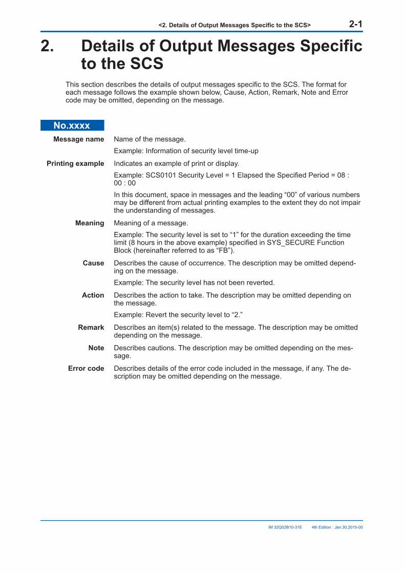
This section describes the details of output messages specific to the SCS. The format foreach message follows the example shown below, Cause, Action, Remark, Note and Errorcode may be omitted, depending on the message.
No.xxxxMessage name Name of the message.
Example: Information of security level time-up
Printing example Indicates an example of print or display.Example: SCS0101 Security Level = 1 Elapsed the Specified Period = 08 :00 : 00In this document, space in messages and the leading “00” of various numbersmay be different from actual printing examples to the extent they do not impairthe understanding of messages.
Meaning Meaning of a message.Example: The security level is set to “1” for the duration exceeding the timelimit (8 hours in the above example) specified in SYS_SECURE FunctionBlock (hereinafter referred to as “FB”).
Cause Describes the cause of occurrence. The description may be omitted depend-ing on the message.Example: The security level has not been reverted.
Action Describes the action to take. The description may be omitted depending onthe message.Example: Revert the security level to “2.”
Remark Describes an item(s) related to the message. The description may be omitteddepending on the message.
Note Describes cautions. The description may be omitted depending on the mes-sage.
Error code Describes details of the error code included in the message, if any. The de-scription may be omitted depending on the message.
<2. Details of Output Messages Specific to the SCS> 2-1
IM 32Q02B10-31E 4th Edition : Jan.30,2015-00
2.1 System Alarms (Message Numbers 4101through 4199)
This section describes system alarm messages issued from the SCS.
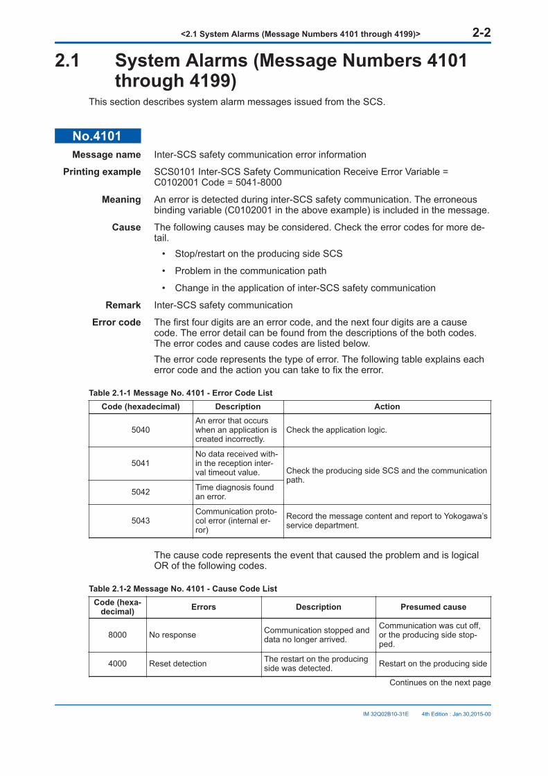
No.4101Message name Inter-SCS safety communication error information
Printing example SCS0101 Inter-SCS Safety Communication Receive Error Variable =C0102001 Code = 5041-8000
Meaning An error is detected during inter-SCS safety communication. The erroneousbinding variable (C0102001 in the above example) is included in the message.
Cause The following causes may be considered. Check the error codes for more de-tail.
• Stop/restart on the producing side SCS
• Problem in the communication path
• Change in the application of inter-SCS safety communication
Remark Inter-SCS safety communication
Error code The first four digits are an error code, and the next four digits are a causecode. The error detail can be found from the descriptions of the both codes.The error codes and cause codes are listed below.The error code represents the type of error. The following table explains eacherror code and the action you can take to fix the error.
Table 2.1-1 Message No. 4101 - Error Code ListCode (hexadecimal) Description Action
5040An error that occurswhen an application iscreated incorrectly.
Check the application logic.
5041No data received with-in the reception inter-val timeout value. Check the producing side SCS and the communication
path.5042 Time diagnosis found
an error.
5043Communication proto-col error (internal er-ror)
Record the message content and report to Yokogawa’sservice department.
The cause code represents the event that caused the problem and is logicalOR of the following codes.
Table 2.1-2 Message No. 4101 - Cause Code ListCode (hexa-
decimal) Errors Description Presumed cause
8000 No response Communication stopped anddata no longer arrived.
Communication was cut off,or the producing side stop-ped.
4000 Reset detection The restart on the producingside was detected. Restart on the producing side
Continues on the next page
<2.1 System Alarms (Message Numbers 4101 through 4199)> 2-2
IM 32Q02B10-31E 4th Edition : Jan.30,2015-00
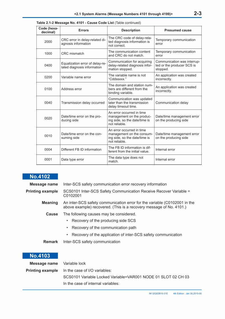
Table 2.1-2 Message No. 4101 - Cause Code List (Table continued)Code (hexa-
decimal) Errors Description Presumed cause
2000 CRC error in delay-related di-agnosis information
The CRC code of delay-rela-ted diagnosis information isnot correct.
Temporary communicationerror
1000 CRC mismatch The communication contentand CRC do not match.
Temporary communicationerror
0400 Equalization error of delay-re-lated diagnosis information
Communication for acquiringdelay-related diagnosis infor-mation stopped.
Communication was interrup-ted or the producer SCS isstopped.
0200 Variable name error The variable name is not“Cddssxxx.”
An application was createdincorrectly.
0100 Address errorThe domain and station num-bers are different from thebinding variable.
An application was createdincorrectly.
0040 Transmission delay occurredCommunication was updatedlater than the transmissiondelay timeout time.
Communication delay
0020 Date/time error on the pro-ducing side
An error occurred in timemanagement on the produc-ing side, so the date/time isnot reliable.
Date/time management erroron the producing side
0010 Date/time error on the con-suming side
An error occurred in timemanagement on the consum-ing side, so the date/time isnot reliable.
Date/time management erroron the producing side
0004 Different FB ID information The FB ID information is dif-ferent from the initial value. Internal error
0001 Data type error The data type does notmatch. Internal error
No.4102Message name Inter-SCS safety communication error recovery information
Printing example SCS0101 Inter-SCS Safety Communication Receive Recover Variable =C0102001
Meaning An inter-SCS safety communication error for the variable (C0102001 in theabove example) recovered. (This is a recovery message of No. 4101.)
Cause The following causes may be considered.• Recovery of the producing side SCS
• Recovery of the communication path
• Recovery of the application of inter-SCS safety communication
Remark Inter-SCS safety communication
No.4103Message name Variable lock
Printing example In the case of I/O variables:SCS0101 Variable Locked Variable=VAR001 NODE 01 SLOT 02 CH 03In the case of internal variables:
<2.1 System Alarms (Message Numbers 4101 through 4199)> 2-3
IM 32Q02B10-31E 4th Edition : Jan.30,2015-00
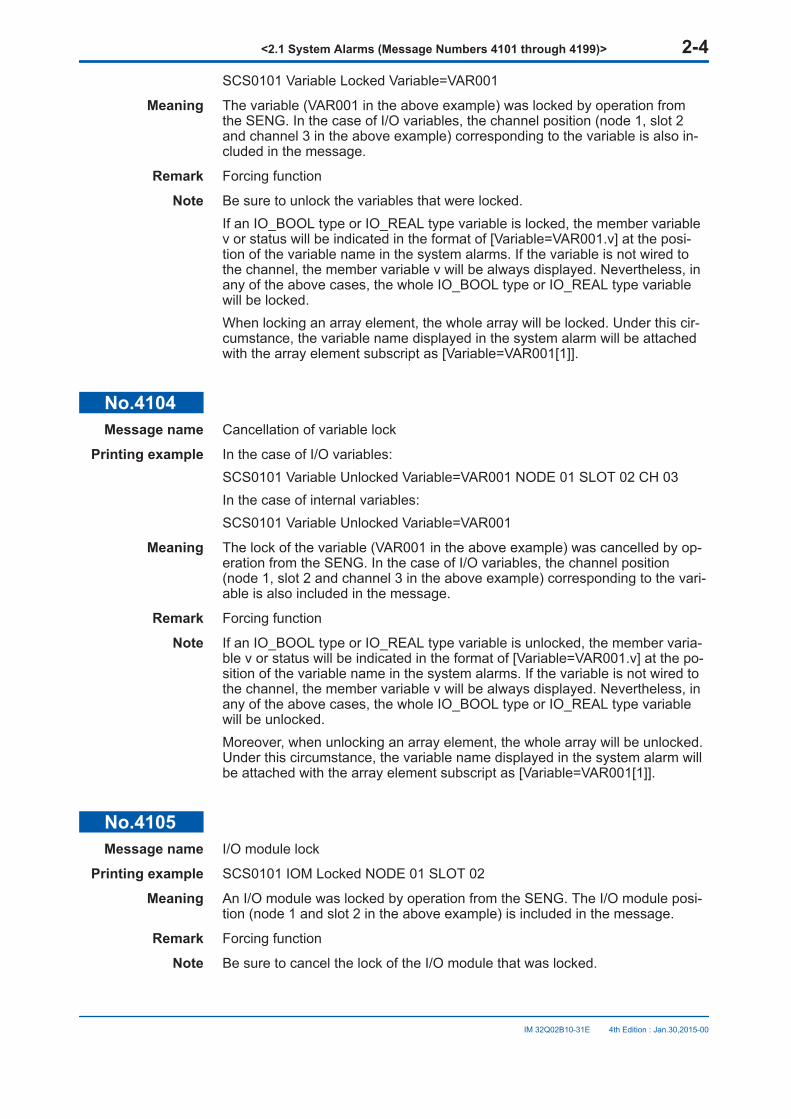
SCS0101 Variable Locked Variable=VAR001
Meaning The variable (VAR001 in the above example) was locked by operation fromthe SENG. In the case of I/O variables, the channel position (node 1, slot 2and channel 3 in the above example) corresponding to the variable is also in-cluded in the message.
Remark Forcing function
Note Be sure to unlock the variables that were locked.If an IO_BOOL type or IO_REAL type variable is locked, the member variablev or status will be indicated in the format of [Variable=VAR001.v] at the posi-tion of the variable name in the system alarms. If the variable is not wired tothe channel, the member variable v will be always displayed. Nevertheless, inany of the above cases, the whole IO_BOOL type or IO_REAL type variablewill be locked.When locking an array element, the whole array will be locked. Under this cir-cumstance, the variable name displayed in the system alarm will be attachedwith the array element subscript as [Variable=VAR001[1]].
No.4104Message name Cancellation of variable lock
Printing example In the case of I/O variables:SCS0101 Variable Unlocked Variable=VAR001 NODE 01 SLOT 02 CH 03In the case of internal variables:SCS0101 Variable Unlocked Variable=VAR001
Meaning The lock of the variable (VAR001 in the above example) was cancelled by op-eration from the SENG. In the case of I/O variables, the channel position(node 1, slot 2 and channel 3 in the above example) corresponding to the vari-able is also included in the message.
Remark Forcing function
Note If an IO_BOOL type or IO_REAL type variable is unlocked, the member varia-ble v or status will be indicated in the format of [Variable=VAR001.v] at the po-sition of the variable name in the system alarms. If the variable is not wired tothe channel, the member variable v will be always displayed. Nevertheless, inany of the above cases, the whole IO_BOOL type or IO_REAL type variablewill be unlocked.Moreover, when unlocking an array element, the whole array will be unlocked.Under this circumstance, the variable name displayed in the system alarm willbe attached with the array element subscript as [Variable=VAR001[1]].
No.4105Message name I/O module lock
Printing example SCS0101 IOM Locked NODE 01 SLOT 02
Meaning An I/O module was locked by operation from the SENG. The I/O module posi-tion (node 1 and slot 2 in the above example) is included in the message.
Remark Forcing function
Note Be sure to cancel the lock of the I/O module that was locked.
<2.1 System Alarms (Message Numbers 4101 through 4199)> 2-4
IM 32Q02B10-31E 4th Edition : Jan.30,2015-00

No.4106Message name Cancellation of I/O module lock
Printing example SCS0101 IOM Unlocked NODE 01 SLOT 02
Meaning The lock of an I/O module was cancelled by operation from the SENG. The I/Omodule position (node 1 and slot 2 in the above example) is included in themessage.
Remark Forcing function
No.4107Message name All input module locks
Printing example SCS0101 All Input IOM Locked
Meaning All input modules were locked by operation from the SENG.
Remark Forcing function
Note Be sure to cancel the locks of the input modules that were locked.
No.4108Message name Cancellation of all input module locks
Printing example SCS0101 All Input IOM Unlocked
Meaning The locks of all input modules were cancelled by operation from the SENG.
Remark Forcing function
No.4109Message name All output module locks
Printing example SCS0101 All Output IOM Locked
Meaning All output modules were locked by operation from the SENG.
Remark Forcing function
Note Be sure to cancel the locks of the output modules that were locked.
No.4110Message name Cancellation of all output module locks
Printing example SCS0101 All Output IOM Unlocked
Meaning The locks of all output modules were cancelled by operation from the SENG.
Remark Forcing function
No.4111Message name All module locks
Printing example SCS0101 All IOM Locked
Meaning All I/O modules were locked by operation from the SENG.
<2.1 System Alarms (Message Numbers 4101 through 4199)> 2-5
IM 32Q02B10-31E 4th Edition : Jan.30,2015-00

Remark Forcing function
Note Be sure to cancel the locks of the I/O modules that were locked.
No.4112Message name Cancellation of all module locks
Printing example SCS0101 All IOM Unlocked
Meaning The locks of all I/O modules were cancelled by operation from the SENG.
Remark Forcing function
No.4113Message name Number of locks exceeded
Printing example SCS0101 Number of Locks Exceeds the Limit = 3
Meaning The total number of locked variables exceeded the limit count (3 in the aboveexample) specified in SYS_FORCE FB.
Cause This is an operation from the SENG. The number of locks is too many.
Action Cancel the variable locks.
Remark SYS_FORCE FB
Note Lock variables within the limit count.
No.4114Message name Recovery from exceeded number of locks
Printing example SCS0101 Number of Locks Within the Limit = 3
Meaning The total number of locked variables is reduced to within the limit count (3 inthe above example) specified in SYS_FORCE FB. (This is a recovery mes-sage of No. 4113.)
Cause This is an operation from the SENG.
Remark SYS_FORCE FB
No.4115Message name Override setting
Printing example SCS0101 TAG001 Overridden (Instance = OVR0001)
Meaning Override operation was performed for the override FB (OVR0001 in the aboveexample) that corresponds to the tag name (TAG001 in the above example)from the HIS.
Remark OVR_B, OVR_I, OVR_R, OVR_IB, OVR_IR, GOV_B, GOV_IB FB
No.4116Message name Cancellation of override
Printing example SCS0101 TAG001 Override Released (Instance = OVR0001)
<2.1 System Alarms (Message Numbers 4101 through 4199)> 2-6
IM 32Q02B10-31E 4th Edition : Jan.30,2015-00
Meaning An override was cancelled for the override FB (OVR0001 in the above exam-ple) that corresponds to the tag name (TAG001 in the above example) fromthe HIS.
Remark OVR_B, OVR_I, OVR_R, OVR_IB, OVR_IR, GOV_B, GOV_IB FB
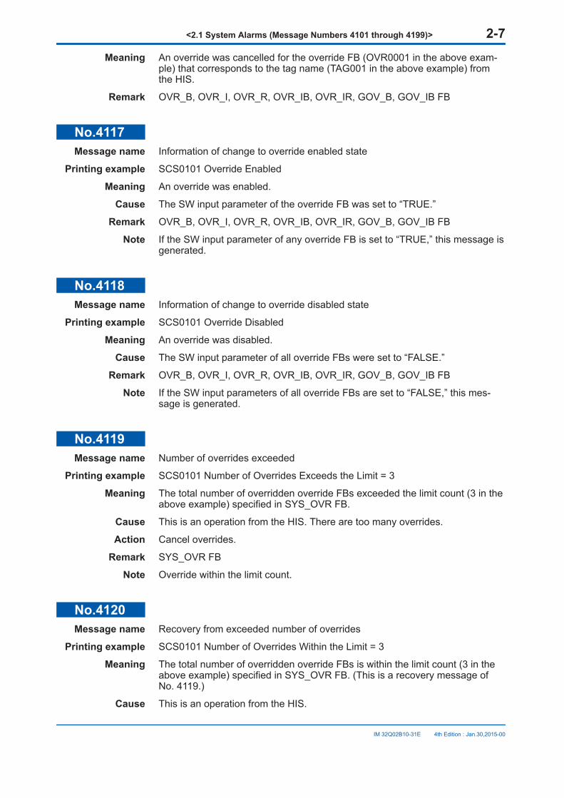
No.4117Message name Information of change to override enabled state
Printing example SCS0101 Override Enabled
Meaning An override was enabled.
Cause The SW input parameter of the override FB was set to “TRUE.”
Remark OVR_B, OVR_I, OVR_R, OVR_IB, OVR_IR, GOV_B, GOV_IB FB
Note If the SW input parameter of any override FB is set to “TRUE,” this message isgenerated.
No.4118Message name Information of change to override disabled state
Printing example SCS0101 Override Disabled
Meaning An override was disabled.
Cause The SW input parameter of all override FBs were set to “FALSE.”
Remark OVR_B, OVR_I, OVR_R, OVR_IB, OVR_IR, GOV_B, GOV_IB FB
Note If the SW input parameters of all override FBs are set to “FALSE,” this mes-sage is generated.
No.4119Message name Number of overrides exceeded
Printing example SCS0101 Number of Overrides Exceeds the Limit = 3
Meaning The total number of overridden override FBs exceeded the limit count (3 in theabove example) specified in SYS_OVR FB.
Cause This is an operation from the HIS. There are too many overrides.
Action Cancel overrides.
Remark SYS_OVR FB
Note Override within the limit count.
No.4120Message name Recovery from exceeded number of overrides
Printing example SCS0101 Number of Overrides Within the Limit = 3
Meaning The total number of overridden override FBs is within the limit count (3 in theabove example) specified in SYS_OVR FB. (This is a recovery message ofNo. 4119.)
Cause This is an operation from the HIS.
<2.1 System Alarms (Message Numbers 4101 through 4199)> 2-7
IM 32Q02B10-31E 4th Edition : Jan.30,2015-00
Remark SYS_OVR FB
No.4121Message name Number of enabled overrides exceeded
Printing example SCS0101 Number of Enabled OVR FBs Exceeds the Limit = 3
Meaning The total number of override FBs in the override enabled state exceeded thelimit count (3 in the above example) specified in SYS_OVR FB.
Action Disable override FBs.
Remark SYS_OVR FB
Note Enable overrides within the limit count.
No.4122Message name Recovery from exceeded number of enabled overrides
Printing example SCS0101 Number of Enabled OVR FBs Within the Limit = 3
Meaning The total number of override FBs in the override enabled state is within thelimit count (3 in the above example) specified in SYS_OVR FB. (This is a re-covery message of No. 4121.)
Remark SYS_OVR FB
No.4123Message name Number of active PASSWD FBs exceeded
Printing example SCS0101 Number of Activated PASSWD FBs Exceeds the Limit = 3
Meaning The total number of active PASSWD FBs exceeded the limit count (3 in theabove example) specified in SYS_PSWD FB.
Cause This is an operation from the HIS. There are too many active PASSWD FBs.
Action Inactivate (reset to OFF) the PASSWD FBs that have exceeded the limitcount.
Remark SYS_PSWD FB
Note Make PASSWD FBs active within the limit count.
No.4124Message name Recovery from exceeded number of active PASSWD FBs
Printing example SCS0101 Number of Activated PASSWD FBs Within the Limit = 3
Meaning The total number of active PASSWD FBs is within the limit count (3 in theabove example) specified in SYS_PSWD FB. (This is a recovery message ofNo. 4123.)
Cause Active PASSWD FBs were inactivated (reset to OFF) by operation from theHIS.
Remark SYS_PSWD FB
<2.1 System Alarms (Message Numbers 4101 through 4199)> 2-8
IM 32Q02B10-31E 4th Edition : Jan.30,2015-00
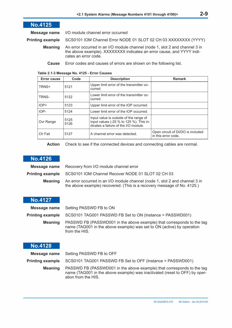
No.4125Message name I/O module channel error occurred
Printing example SCS0101 IOM Channel Error NODE 01 SLOT 02 CH 03 XXXXXXXX (YYYY)
Meaning An error occurred in an I/O module channel (node 1, slot 2 and channel 3 inthe above example). XXXXXXXX indicates an error cause, and YYYY indi-cates an error code.
Cause Error codes and causes of errors are shown on the following list.
Table 2.1-3 Message No. 4125 - Error CausesError cause Code Description Remark
TRNS+ 5121 Upper limit error of the transmitter oc-curred.
TRNS- 5122 Lower limit error of the transmitter oc-curred.
IOP+ 5123 Upper limit error of the IOP occurred.
IOP- 5124 Lower limit error of the IOP occurred.
Ovr Range 51255126
Input value is outside of the range ofinput values (-25 % to 125 %). This in-dicates a failure of the I/O module.
Ch Fail 5127 A channel error was detected. Open circuit of DI/DO is includedin this error code.
Action Check to see if the connected devices and connecting cables are normal.
No.4126Message name Recovery from I/O module channel error
Printing example SCS0101 IOM Channel Recover NODE 01 SLOT 02 CH 03
Meaning An error occurred in an I/O module channel (node 1, slot 2 and channel 3 inthe above example) recovered. (This is a recovery message of No. 4125.)
No.4127Message name Setting PASSWD FB to ON
Printing example SCS0101 TAG001 PASSWD FB Set to ON (Instance = PASSWD001)
Meaning PASSWD FB (PASSWD001 in the above example) that corresponds to the tagname (TAG001 in the above example) was set to ON (active) by operationfrom the HIS.
No.4128Message name Setting PASSWD FB to OFF
Printing example SCS0101 TAG001 PASSWD FB Set to OFF (Instance = PASSWD001)
Meaning PASSWD FB (PASSWD001 in the above example) that corresponds to the tagname (TAG001 in the above example) was inactivated (reset to OFF) by oper-ation from the HIS.
<2.1 System Alarms (Message Numbers 4101 through 4199)> 2-9
IM 32Q02B10-31E 4th Edition : Jan.30,2015-00
No.4129Message name GPS interface unit error
Printing example SCS0101 GPS Interface Unit Error (RIGHT CPU)
Meaning A CPU module (right side in the above example) detected a GPS unit error ortime synchronization error.
Cause The following causes may be considered.• Problem in the cable connecting the GPS unit and the GPS interface unit.
• Failure of the GPS interface unit
Action Check to see if a cable connecting the GPS unit and the GPS interface unit isdisconnected or cut. Also, check to see if a terminator is connected to theends of the cable. If everything is in place, replace the GPS interface unit.
Note If this message is displayed while the time synchronization method is V nettime synchronization, the CPU module may be faulty.
No.4130Message name Recovery of GPS interface unit
Printing example SCS0101 GPS Interface Unit Recover (RIGHT CPU)
Meaning Time synchronization of the GPS unit detected by CPU module (right side inthe above example) is recovered. (This is a recovery message of No. 4129.)
No.4131Message name Communication module lock
Printing example 1 SCS0101 Communication Module All Inputs/Outputs Locked NODE 01 SLOT02
Printing example 2 SCS0101 Communication Module All Inputs Locked NODE 01 SLOT 02
Printing example 3 SCS0101 Communication Module All Outputs Locked NODE 01 SLOT 02
Meaning The communication module was locked by operation from the SENG. Themessage varies depending on the locked range (inputs and outputs, inputs on-ly or outputs only). The location of the communication module is also includedin the messages (such as node 1, slot 2).
Remark Forcing function, subsystem communication
Note Be sure to cancel the lock of the communication module that was locked.
No.4132Message name Cancellation of Communication module lock
Printing example 1 SCS0101 Communication Module All Inputs/Outputs Unlocked NODE 01SLOT 02
Printing example 2 SCS0101 Communication Module All Inputs Unlocked NODE 01 SLOT 02
Printing example 3 SCS0101 Communication Module All Outputs Unlocked NODE 01 SLOT 02
Meaning The lock of the communication module was cancelled by operation from theSENG. The message varies depending on the locked range (inputs and out-
<2.1 System Alarms (Message Numbers 4101 through 4199)> 2-10
IM 32Q02B10-31E 4th Edition : Jan.30,2015-00
puts, inputs only or outputs only). The location of the communication module isalso included in the messages (such as node 1, slot 2).
Remark Forcing function, subsystem communication
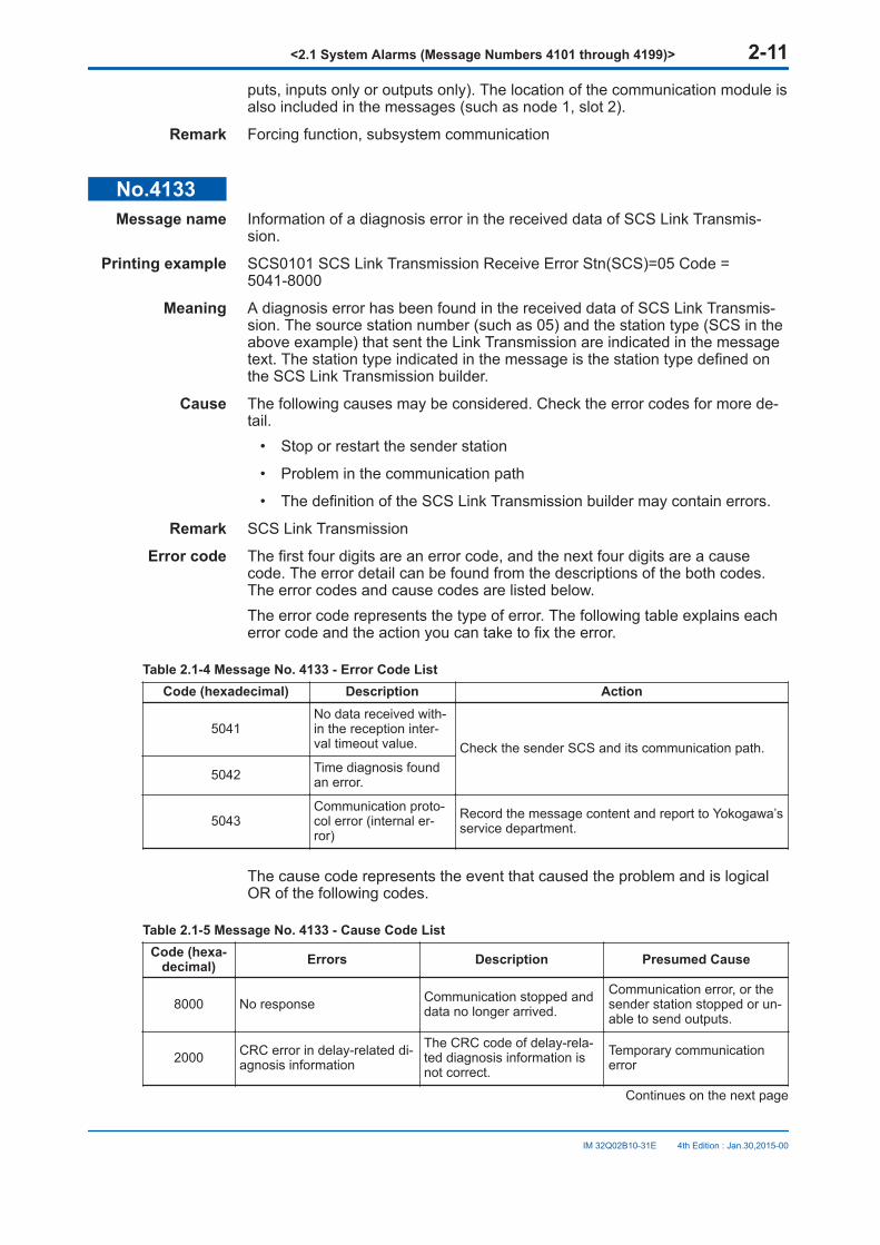
No.4133Message name Information of a diagnosis error in the received data of SCS Link Transmis-
sion.
Printing example SCS0101 SCS Link Transmission Receive Error Stn(SCS)=05 Code =5041-8000
Meaning A diagnosis error has been found in the received data of SCS Link Transmis-sion. The source station number (such as 05) and the station type (SCS in theabove example) that sent the Link Transmission are indicated in the messagetext. The station type indicated in the message is the station type defined onthe SCS Link Transmission builder.
Cause The following causes may be considered. Check the error codes for more de-tail.
• Stop or restart the sender station
• Problem in the communication path
• The definition of the SCS Link Transmission builder may contain errors.
Remark SCS Link Transmission
Error code The first four digits are an error code, and the next four digits are a causecode. The error detail can be found from the descriptions of the both codes.The error codes and cause codes are listed below.The error code represents the type of error. The following table explains eacherror code and the action you can take to fix the error.
Table 2.1-4 Message No. 4133 - Error Code ListCode (hexadecimal) Description Action
5041No data received with-in the reception inter-val timeout value. Check the sender SCS and its communication path.
5042 Time diagnosis foundan error.
5043Communication proto-col error (internal er-ror)
Record the message content and report to Yokogawa’sservice department.
The cause code represents the event that caused the problem and is logicalOR of the following codes.
Table 2.1-5 Message No. 4133 - Cause Code ListCode (hexa-
decimal) Errors Description Presumed Cause
8000 No response Communication stopped anddata no longer arrived.
Communication error, or thesender station stopped or un-able to send outputs.
2000 CRC error in delay-related di-agnosis information
The CRC code of delay-rela-ted diagnosis information isnot correct.
Temporary communicationerror
Continues on the next page
<2.1 System Alarms (Message Numbers 4101 through 4199)> 2-11
IM 32Q02B10-31E 4th Edition : Jan.30,2015-00
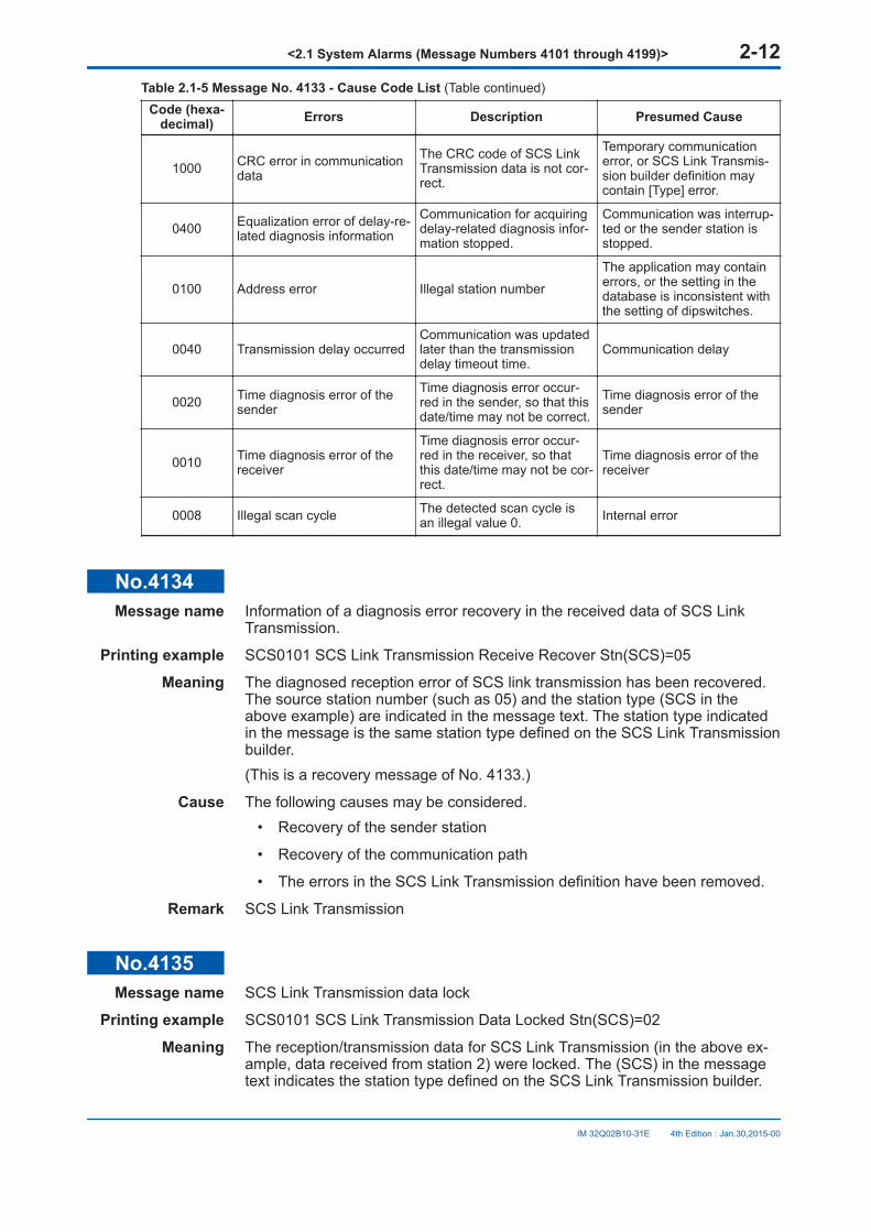
Table 2.1-5 Message No. 4133 - Cause Code List (Table continued)Code (hexa-
decimal) Errors Description Presumed Cause
1000 CRC error in communicationdata
The CRC code of SCS LinkTransmission data is not cor-rect.
Temporary communicationerror, or SCS Link Transmis-sion builder definition maycontain [Type] error.
0400 Equalization error of delay-re-lated diagnosis information
Communication for acquiringdelay-related diagnosis infor-mation stopped.
Communication was interrup-ted or the sender station isstopped.
0100 Address error Illegal station number
The application may containerrors, or the setting in thedatabase is inconsistent withthe setting of dipswitches.
0040 Transmission delay occurredCommunication was updatedlater than the transmissiondelay timeout time.
Communication delay
0020 Time diagnosis error of thesender
Time diagnosis error occur-red in the sender, so that thisdate/time may not be correct.
Time diagnosis error of thesender
0010 Time diagnosis error of thereceiver
Time diagnosis error occur-red in the receiver, so thatthis date/time may not be cor-rect.
Time diagnosis error of thereceiver
0008 Illegal scan cycle The detected scan cycle isan illegal value 0. Internal error
No.4134Message name Information of a diagnosis error recovery in the received data of SCS Link
Transmission.
Printing example SCS0101 SCS Link Transmission Receive Recover Stn(SCS)=05
Meaning The diagnosed reception error of SCS link transmission has been recovered.The source station number (such as 05) and the station type (SCS in theabove example) are indicated in the message text. The station type indicatedin the message is the same station type defined on the SCS Link Transmissionbuilder.(This is a recovery message of No. 4133.)
Cause The following causes may be considered.• Recovery of the sender station
• Recovery of the communication path
• The errors in the SCS Link Transmission definition have been removed.
Remark SCS Link Transmission
No.4135Message name SCS Link Transmission data lock
Printing example SCS0101 SCS Link Transmission Data Locked Stn(SCS)=02
Meaning The reception/transmission data for SCS Link Transmission (in the above ex-ample, data received from station 2) were locked. The (SCS) in the messagetext indicates the station type defined on the SCS Link Transmission builder.
<2.1 System Alarms (Message Numbers 4101 through 4199)> 2-12
IM 32Q02B10-31E 4th Edition : Jan.30,2015-00
Remark Forcing function, SCS Link Transmission
Note Be sure to cancel the lock of the station that was locked.
No.4136Message name Cancellation of SCS Link Transmission data lock
Printing example SCS0101 SCS Link Transmission Data Unlocked Stn(SCS)=02
Meaning The lock of reception/transmission data for SCS Link Transmission (in theabove example, data received from station 2) was cancelled. The (SCS) in themessage text indicates the station type defined on the SCS Link Transmissionbuilder.
Remark Forcing function, SCS Link Transmission
No.4137Message name Number of Locked Stations in SCS Link Transmission Exceeded
Printing example SCS0101 Number of Locks about SCS Link Transmission Exceeds the Limit =3
Meaning The number of locked stations exceeded the limit (3 in the above example),which is defined in SYS_FORCE_ LT FB as the number of stations allowed forforcing.
Cause Operation from the SENG to lock too many stations.
Action Cancel SCS Link Transmission locks for some SCS.
Remark Forcing function, SCS Link Transmission, SYS_FORCE_LT FB
Note You should not lock stations beyond the limit.
No.4138Message name Recovery from exceeded number of locked stations in SCS Link Transmission
Printing example SCS0101 Number of Locks about SCS Link Transmission Within the Limit = 3
Meaning The number of locked stations fell within the limit (3 in the above example),which is defined in SYS_FORCE_ LT FB as the number of stations allowed forforcing. (This is the recovery message of No.4137.)
Cause Operation from the SENG.
Remark Forcing function, SCS Link Transmission, SYS_FORCE_LT FB
No.4139Message name Inter-SCS Safety Communication data lock
Printing example SCS0101 Inter-SCS Safety Communication Data Locked Dom=01 Stn=02
Meaning The Inter-SCS Safety Communication data received from a producer SCS (inthe above example, station 2 in domain 1) were locked.The message for a lock of the local station (data produced by the station arelocked) is also output in the same format, showing its own domain number andstation number.
<2.1 System Alarms (Message Numbers 4101 through 4199)> 2-13
IM 32Q02B10-31E 4th Edition : Jan.30,2015-00
Remark Forcing function, Inter-SCS Safety Communication
Note Be sure to cancel the lock of the station that was locked.
No.4140Message name Cancellation of Inter-SCS Safety Communication data lock
Printing example SCS0101 Inter-SCS Safety Communication Data Unlocked Dom=01 Stn=02
Meaning The lock of Inter-SCS Safety Communication data received from a producerSCS (in the above example, station 2 in domain 1) was cancelled.The message of cancellation for the lock of local station (data produced by thestation are locked) is also output in the same format, showing its own domainnumber and station number.
Remark Forcing function, Inter-SCS Safety Communication
No.4141Message name Number of locked stations in Inter-SCS Safety Communication exceeded
Printing example SCS0101 Number of Locks about Inter-SCS Safety Communication Exceedsthe Limit = 3
Meaning The number of locked stations exceeded the limit (3 in the above example),which is defined in SYS_FORCE_ BD FB as the number of stations allowedfor forcing.
Cause Operation from the SENG to lock too many stations
Action Cancel Inter-SCS Safety Communication locks for some SCS.
Remark Forcing function, Inter-SCS Safety Communication
Note You should not lock stations beyond the limit.
No.4142Message name Recovery from exceeded number of locked stations in Inter-SCS Safety Com-
munication
Printing example SCS0101 Number of Locks about Inter-SCS Safety Communication Within theLimit = 3
Meaning The number of locked stations fell within the limit (3 in the above example),which is defined in SYS_FORCE_ BD FB as the number of stations allowedfor forcing. (This is the recovery message of No.4141.)
Cause Operation from the SENG
Remark SYS_FORCE_BD FB
No.4143Message name Start of automatic scan period extension
Printing example SCS0101 Scan Period Extended from the Original Scan Period 100ms to200ms
<2.1 System Alarms (Message Numbers 4101 through 4199)> 2-14
IM 32Q02B10-31E 4th Edition : Jan.30,2015-00

Meaning Automatic extension of the scan period of the application logic execution star-ted. (In the above example, the original scan period of 100 ms was extendedto 200 ms.)
Cause The application caused heavy load on the SCS.
Remark SYS_SCANEXT FB, automatic scan period extension
No.4144Message name Cancellation of automatic scan period extension
Printing example SCS0101 Scan Period Recovered to the Original Scan Period 100ms
Meaning Automatic extension of the scan period of the application logic execution iscancelled. (In the above example, the scan period recovered to its original pe-riod of 100 ms.)
Cause The load on the SCS caused by the application was reduced.
Remark SYS_SCANEXT FB, automatic scan period extension
No.4145Message name Abnormal calculation occurred
Printing example 1 SCS0101 Calculation Error (XXXXXX) Program=PG01
Printing example 2 SCS0101 Calculation Error (XXXXXX) Program=PG01 FU/FB=UFB01
Meaning Abnormal calculation occurred in the application logic.XXXXXX indicates the type of abnormal calculation. The types are as follows:Div by Zero : Division by zeroAccess to the Outside of Array : Access to the outside of an arrayFPU Overflow : Overflow in the floating-point calculationCast Overflow : Overflow in casting
At “Program=”, the name of the program (POU name) where the abnormal cal-culation occurred is indicated. If the abnormal calculation occurred in a user-defined FU/FB, the POU name of that FU/FB is indicated at “FU/FB=.”
Cause Error in the application
Remark SYS_CERR FB
No.4146Message name Recovery from abnormal calculation
Printing example 1 SCS0101 Calculation Recover (XXXXXX) Program=PG01
Printing example 2 SCS0101 Calculation Recover (XXXXXX) Program=PG01 FU/FB=UFB01
Meaning Indicates a recovery from the abnormal calculation occurred in the applicationlogic.XXXXXX indicates the type of abnormal calculation. The types are as follows:Div by Zero : Division by zeroAccess to the Outside of Array : Access to the outside of an arrayFPU Overflow : Overflow in the floating-point calculation
<2.1 System Alarms (Message Numbers 4101 through 4199)> 2-15
IM 32Q02B10-31E 4th Edition : Jan.30,2015-00

Cast Overflow : Overflow in casting
At “Program=”, the name of the program (POU name) where the abnormal cal-culation occurred is indicated. If the abnormal calculation occurred in a user-defined FU/FB, the POU name of that FU/FB is indicated at “FU/FB=.”
Cause The error in the application was corrected.
Remark SYS_CERR FB
No.4151Message name Information of retainable data initialization
Printing example SCS0101 Retain Data Initialized
Meaning Retainable data have been initialized.
Cause • Database with different CRC codes or generation time was offline-down-loaded to the SCS.
• Data saved in the memory with backup battery volatilized.
Action Set the setting values of the external communication function blocks with dataretaining function again.
Remark Data retaining function, external communication function blocks with data re-taining function (ECWR_B, ECWR_I, ECWR_R), ACCUM FB, AGA_R FB
No.4152Message name Online change of scan period
Printing example SCS0101 Scan Period Changed to 200ms
Meaning The scan period of the application logic was changed by online change down-load.
Cause Operation from the SENG
Remark Online change download
No.4153Message name Information of Inter-SCS Safety Communication data lock time-up
Printing example SCS0101 Inter-SCS Safety Communication Data Lock Elapsed the SpecifiedPeriod = 08:00:00
Meaning Inter-SCS Safety Communication lock exceeded the time limit (8 hours in theabove example) specified in SYS_FORCE_BD FB.
Action Check whether all Inter-SCS Safety Communication locks have been cancel-led and cancel unnecessary locks.
Remark Forcing function, Inter-SCS Safety Communication, SYS_FORCE_BD FB
No.4154Message name Information of forced cancellation of Inter-SCS Safety Communication data
locks
Printing example SCS0101 All Inter-SCS Safety Communication Data Unlocked.
<2.1 System Alarms (Message Numbers 4101 through 4199)> 2-16
IM 32Q02B10-31E 4th Edition : Jan.30,2015-00
Meaning Locks of all the Inter-SCS Safety Communication data (reception/transmis-sion) in the station were forcibly cancelled.
Cause Locks of all the Inter-SCS Safety Communication data were cancelled by us-ing the SYS_FORCE_BD FB.
Remark Forcing function, Inter-SCS Safety Communication, SYS_FORCE_BD FB
No.4155Message name Information of SCS Link Transmission status change.
Printing example SCS0101 SCS Link Transmission Data Status Set to TRUE Old=FALSEStn(SCS)=03
Meaning The data status of SCS Link Transmission (such as from station 03) has beenchanged (For an example, changed from FALSE to TRUE). The (SCS) in themessage text indicates the station type defined on the SCS Link Transmissionbuilder.
Remark Forcing function
No.4156Message name Information of SCS Link Transmission definition change
Printing example SCS0101 SCS Link Transmission Definition Changed
Meaning SCS Link Transmission definitions were changed by online change download.
Cause Online change download was executed from the SENG.
No.4157Message name Information of SCS Link Transmission wiring change
Printing example SCS0101 SCS Link Transmission Wiring Changed
Meaning SCS Link Transmission wirings were changed by online change download.
Cause Online change download was executed from the SENG.
No.4158Message name Information of SCS Link Transmission lock time-up
Printing example SCS0101 SCS Link Transmission Data Lock Elapsed the Specified Period =08:00:00
Meaning SCS Link Transmission lock continued exceeding the time limit (8 hours in theabove example) specified in SYS_FORCE_LT FB.
Action Check whether all SCS Link Transmission locks have been cancelled, andcancel unnecessary locks.
Remark Forcing function, SCS Link Transmission, SYS_FORCE_LT FB
No.4159Message name Information of forced cancellation of SCS Link Transmission locks
Printing example SCS0101 All SCS Link Transmission Data Unlocked
<2.1 System Alarms (Message Numbers 4101 through 4199)> 2-17
IM 32Q02B10-31E 4th Edition : Jan.30,2015-00
Meaning Locks of all the locked SCS Link Transmission were forcibly cancelled.
Cause Locks of all SCS Link Transmission were cancelled by operation usingSYS_FORCE_LT FB.
Remark Forcing function, SCS Link Transmission, SYS_FORCE_LT FB
No.4160Message name Invalid password for Manual Operation FB
Printing example SCS0101 TAG001 Specified Invalid Password
Meaning The password string specified for Manual Operation FB (MOB_21, MOB_11,MOA) from the HIS is invalid.
Cause The password entered from the HIS and the password set in Manual Opera-tion FB did not match.
Action Enter the correct password for Manual Operation FB again.
Remark Manual Operation FB (MOB_21, MOB_11, MOA)
No.4161Message name Information of Output IOM Shutdown
Printing example 1 SCS0101 All Output IOM Shutdown
Printing example 2 SCS0101 Output IOM Shutdown NODE 01 SLOT 02
Meaning An output IOM shutdown task is performed by a Shutdown FB (SYS_ALLSDor SYS_IOSD). If the shutdown task is performed by SYS_IOSD, the outputmodule location for shutting down (node 1 and slot 2 in the above example) isalso included in the message.
Remark SYS_ALLSD, SYS_IOSD
No.4162Message name Information of communication I/O definition change
Printing example SCS0101 Communication Definition Changed
Meaning The communication I/O definitions of the communication module werechanged by online change download.
Cause Online change download was executed from the SENG.
No.4163Message name Information of communication I/O wiring change
Printing example SCS0101 Communication I/O Wiring Changed
Meaning The communication I/O wirings were changed by online change download.
Cause Online change download was executed from the SENG.
No.4164Message name Information of disabling security level change
<2.1 System Alarms (Message Numbers 4101 through 4199)> 2-18
IM 32Q02B10-31E 4th Edition : Jan.30,2015-00
Printing example SCS0101 Security Levels Change Disabled
Meaning The security level change of the SCS by a password-authenticated operationperformed from SENG is disabled.
Remark SYS_SEC_CTL FB
No.4165Message name Information of enabling security level change
Printing example SCS0101 Security Levels Change Enabled
Meaning The security level change of the SCS by a password-authenticated operationperformed from SENG is enabled.
Remark SYS_SEC_CTL FB
No.4166Message name Information of communication module lock time-up
Printing example SCS0101 Communication Module Lock Elapsed the Specified Period =08:00:00
Meaning The communication module lock continued exceeding the time limit (8 hours inthe above example) specified in SYS_FORCE_SC FB.
Action Check whether all communication module locks have been cancelled, andcancel unnecessary locks.
Remark Forcing function, subsystem communication, SYS_FORCE_SC FB
No.4167Message name Information of forced cancellation of communication module locks
Printing example SCS0101 All Communication Modules Unlocked
Meaning Locks of all communication modules were forcibly cancelled.
Cause Locks of all communication modules were cancelled by operation usingSYS_FORCE_SC FB.
Remark Forcing function, subsystem communication, SYS_FORCE_SC FB
No.4168Message name Information of tag name change by online change download
Printing example SCS0101 Online Change Download Tag Name = TAG001 Changed
Meaning The tag name (TAG001 in the above example) of PASSWD FB or override FBwas changed by online change download.
Cause Online change download was executed from the SENG.
No.4169Message name NVRAM diagnosis error
Printing example SCS0101 RIGHT NVRAM Diagnosis Error
<2.1 System Alarms (Message Numbers 4101 through 4199)> 2-19
IM 32Q02B10-31E 4th Edition : Jan.30,2015-00

Meaning An error was detected during diagnosis of NVRAM (nonvolatile memory) in aCPU module (right side in the above example).
Cause NVRAM may be faulty.
Action Replace the applicable CPU module.
No.4170Message name Flash memory diagnosis error
Printing example SCS0101 RIGHT Flash Memory Diagnosis Error
Meaning An error was detected during self-diagnosis of flash memory in a CPU module(right side in the above example).
Cause Part of data stored in flash memory was destroyed, or flash memory may befaulty.
Action If the SCS is in a single CPU module configuration, the SCS will not be able tostart when this CPU restarts next time. It is necessary to change the CPUmodule right away.If the SCS is configured with redundant CPU modules, the control will switchto the other module after detecting this error, and the module where the erroroccurs is restarted as a standby module.If the error is caused by damage to the data in the flash memory, data in thecontrol side will be copied to the standby module where the error occurs, andthat module will then recover from abnormal to normal status.If the error is caused by the physical damage of the flash memory, this systemalarm will occur even after the damaged CPU is switched to standby. Underthis circumstance, it is necessary to change the damaged CPU module.
No.4172Message name Information of resource change by online change download
Printing example SCS0101 Online Change Download Resource Changed (Total POU=10)
Meaning The resource was changed by online change download. The resource definestotal number of POU (10 in the above example).
Cause Online change download was executed from the SENG.
Action Check and confirm that the total number of POU indicated in this message isequal to the total number of POU indicated by Database Validity Check Tool.
No.4173Message name Completion of writing to flash memory
Printing example SCS0101 Writing XXXXXX to Flash Memory Succeeded
Meaning Writing to flash memory in a CPU module was normally completed.XXXXXX: Indicates the data written. The items of the data are as follows.Security Password : Security passwordSystem Database : System databaseIntegration Database : Integration databaseVariable Database : Variable database
<2.1 System Alarms (Message Numbers 4101 through 4199)> 2-20
IM 32Q02B10-31E 4th Edition : Jan.30,2015-00

Difference Data : Difference data
Cause When online change download from SENG to SCS was executed or the pass-word was changed, data was normally written to flash memory.
No.4174Message name Failed to write to flash memory
Printing example SCS0101 Writing XXXXX to Flash Memory Error
Meaning Write data error was detected during check at flash memory write in a CPUmodule.XXXXXX: Indicates the data attempted to be written. The items of the data areas follows.Security Password : Security passwordSystem Database : System databaseIntegration Database : Integration databaseVariable Database : Variable databaseDifference Data : Difference data
Cause Flash memory may be faulty.
Action If the SCS is in a single CPU module configuration, the CPU module continuesthe operation even if this error occurs. However, the SCS will not start properlywhen this CPU module restarts next time. It is necessary to change the CPUmodule as soon as possible.On a dual-redundant CPU module configuration SCS, if this writing error toflush memory occurs on one of the CPU modules, the CPU module will befailed and operation is continued with the other CPU module. It is necessary tochange the failed CPU module right away. If writing to the flash memories inboth CPU modules fails, the SCS will not be able to start when the CPU re-starts. Under this circumstance, it is necessary to change both CPU modulesright away.
Remark Flash memory diagnosis
No.4175Message name Failed to update external communication data
Printing example SCS0101 External Data Refresh Failed
Meaning The SCS has failed to update external communication data. This data is refer-enced in communications with CENTUM stations and Modbus, so when thiserror occurs, data will not be updated in those stations.
Cause The CPU processing time allocated for the external communication functionprocessing was not sufficient. As a result, processing to update the externalcommunication data is not performed.
Action Reduce the communication load on the SCS. If this error occurs regularly, re-view the balance between the application logic amount and the scan period.
No.4177Message name Information of SCS security level change
<2.1 System Alarms (Message Numbers 4101 through 4199)> 2-21
IM 32Q02B10-31E 4th Edition : Jan.30,2015-00
Printing example SCS0101 Security Level Changed to 1
Meaning The security level of the SCS was changed (1 in the above example).
Cause The security level of the SCS was changed. The security level can be changedfrom the SENG or SYS_SECURE FB.
Note Be sure to revert the security level to “2.”
No.4178Message name Information of security level time-up
Printing example SCS0101 Security Level = 1 Elapsed the Specified Period = 08:00:00
Meaning The security level is set to “1” for the duration exceeding the time limit (8 hoursin the above example) specified in SYS_SECURE FB.
Cause The security level has not been reverted.
Action Revert the security level to “2.”
Remark SYS_SECURE FB
Note When the security level is “0,” the message is not generated.
No.4179Message name Information of communication I/O module output enabled operation
Printing example SCS0101 Communication Modules Output Enabled
Meaning The communication modules are enabled for output.
Remark I/O Channel Status dialog box, SYS_STAT_SC FB
Note This is irrelevant for enabling the output of the safety I/O modules. If you havedone the Output enabled operation for the safety output modules, confirm themessage 4181.
No.4180Message name Information of password change
Printing example SCS0101 Security Level = 1 Password was Changed
Meaning The password for the SCS security level (1 in the above example) waschanged.
Cause The password was changed from the SENG.
Note The message of No. 4173 is also generated after this alarm.
No.4181Message name Information of output enabled operation
Printing example SCS0101 Output Enabled
Meaning The output enabled operation for the SCS was performed from the SENG.When all the safety module’s output channels go into “output-enabled” state,the SCS’s operating mode changes to “Running.”
Remark I/O Channels Status dialog box, SYS_STAT_FB
<2.1 System Alarms (Message Numbers 4101 through 4199)> 2-22
IM 32Q02B10-31E 4th Edition : Jan.30,2015-00
No.4182Message name Information of output module start operation
Printing example SCS0101 IOM Started NODE 01 SLOT 02
Meaning An output module (node 1 and slot 2 in the above example) was started fromthe SENG.
Remark SCS State Management window
No.4183Message name Request to upload SOE to SENG
Printing example SCS0101 SOE Save Request
Meaning This notification prompts to upload the event information collected on the SCSto SENG.
Cause This message is generated every time 12,000 events have occurred on theSCS.
Action Start SOE Viewer on SENG and upload events from SCS.
Remark SOER function
Note This system alarm is generated even if SOE Viewer is started periodically.Events can be uploaded from the SCS by starting SOE Viewer and displayingthe latest event.
No.4184Message name Notification on saving SOE trip signal file in SCS
Printing example SCS0101 SOE Trip Signal File No.= 01 Saved
Meaning The SOE trip signal file (No. 01 in the above example) was saved in SCS.
Action Start SOE Viewer on SENG and upload the events in the file.
Remark SOER function
Note When uploading the events is complete, the trip signal files need to be reset.Up to two trip signal files can be held in the SCS. The trip signal files can bereset by starting the Message Cache Tool and initializing the trip information.
No.4185Message name Information of variable value change
Printing example 1 SCS0101 Variable Set to 10.0 Old = 5.0 Variable = VAR001
Printing example 2 SCS0101 Variable Set to TRUE Old = FALSE Variable = VAR001 NODE 01SLOT 02
Printing example 3 SCS0101 Variable Set to TRUE Old = FALSE Variable = VAR001 NODE 01SLOT 02 CH 03
Printing example 4 SCS0101 Variable Set to TRUE Old = FALSE Variable = VAR001 Stn=02No=025
Meaning The value of the variable (VAR001 in the above example) was changed fromthe SENG. For a communication I/O, a variable corresponds to the communi-cation module location (as shown in example 2, node 1, slot 2) is also included
<2.1 System Alarms (Message Numbers 4101 through 4199)> 2-23
IM 32Q02B10-31E 4th Edition : Jan.30,2015-00
in the message. For an I/O variable, a variable corresponds to the variable lo-cation (as shown in example 3, node 1, slot 2, channel 3) is also included inthe message.The VAR001 in the above printing example 4 is the instance name of the func-tion block that accesses the data of SCS Link Transmission. The related sta-tion number and bit number are also printed.
Remark Forcing function
No.4186Message name Information of lock time-up
Printing example SCS0101 Lock Elapsed the Specified Period = 08:00:00
Meaning Lock continued exceeding the time limit (8 hours in the above example) speci-fied in SYS_FORCE FB.
Action Check whether all locks have been cancelled, and cancel unnecessary locks.
Remark Forcing function, SYS_FORCE FB
No.4187Message name Information of forced cancellation of locks
Printing example SCS0101 All Variables Unlocked
Meaning Locks of all variables were forcibly cancelled.
Cause Locks of all variables were cancelled by operation using SYS_FORCE FB.
Remark Forcing function, SYS_FORCE FB
No.4188Message name Start of online change download
Printing example SCS0101 Online Change Download (System Database) Start
Meaning Online change download to the system database was started.
Remark Download function
No.4189Message name Completion of online change download
Printing example SCS0101 Online Change Download (System Database) Complete
Meaning Online change download to the system database was normally completed.
Remark Download function
No.4190Message name Online change download error
Printing example SCS0101 Online Change Download (System Database) Error = 5340-0001
Meaning Online change download to the system database ended with an error.
<2.1 System Alarms (Message Numbers 4101 through 4199)> 2-24
IM 32Q02B10-31E 4th Edition : Jan.30,2015-00
Cause/Action Causes and actions vary depending on the error code.
Table 2.1-6 Message No. 4190 - Error Causes and ActionsError code Cause Action
5340-**** The security level stays “2.” Set the security level to “1” and then execute onlinechange download again.
Others Internal error Record the message content and report to Yokoga-wa’s service department.
No.4191Message name Completion of I/O definition rewriting
Printing example SCS0101 IOM Definition Changed NODE 01 SLOT 02
Meaning I/O definition was changed by online change download to the system data-base. The I/O module position is included in the message (node 1, slot 2 in theabove example).If the number following “SLOT” is 00, it means that the node definition informa-tion has been changed. The node definition information is changed when youdo the following:
• Change comments of the node
• Add or delete I/O modules of the node
• Change slots of the I/O modules of the node
• Change the model of the I/O modules of the node
No.4192Message name Information of override state time-up
Printing example SCS0101 Override Elapsed the Specified Period = 08:00:00
Meaning Override continued exceeding the time limit (8 hours in the above example)specified in SYS_OVR FB.
Action Check whether overrides were released, and release unnecessary overrides.
Remark SYS_OVR FB
No.4193Message name Information of forced release of all overrides
Printing example SCS0101 All Overrides Released
Meaning The overrides for all variables were forcibly released.
Cause The overrides for all variables were forcibly released by operation usingSYS_OVR FB.
Remark SYS_OVR FB
No.4194Message name Information of override enabled state time-up
Printing example SCS0101 Enabled OVR FB Elapsed the Specified Period = 08:00:00
<2.1 System Alarms (Message Numbers 4101 through 4199)> 2-25
IM 32Q02B10-31E 4th Edition : Jan.30,2015-00
Meaning The override enabled state continued exceeding the time limit (8 hours in theabove example) specified in SYS_OVR FB.
Cause Check override FB in the override enabled state, and release unnecessaryoverride enabled state.
Remark SYS_OVR FB
No.4195Message name Information of communication I/O data status change
Printing example SCS0101 Communication Data Status Set to TRUE Old = FALSE NODE 01SLOT 02 Definition 001
Meaning The data status of the communication I/O (such as node 1, slot 2, definition 1in the above example) was changed (such as from FALSE to TRUE) from theSENG.
Remark Forcing function
No.4196Message name Invalid password for PASSWD FB
Printing example SCS0101 TAG001 PASSWD FB Specified Invalid Password
Meaning The password string specified for PASSWD FB from the HIS is invalid.
Cause The password entered from the HIS and the password set in PASSWD FB didnot match.
Action Specify the correct password for PASSWD FB and enter it again.
Remark PASSWD FB
No.4197Message name Information on active PASSWD FB time-up
Printing example SCS0101 Activated PASSWD FB Elapsed the Specified Period = 10:00:00
Meaning PASSWD FB has been active exceeding the time limit (10 hours in the aboveexample) specified in SYS_PSWD.
Action Deactivate PASSWD FB that is not required to be active.
Remark SYS_PSWD FB
No.4198Message name Information on forced reset of PASSWD FB
Printing example SCS0101 All PASSWD FB Reset to OFF
Meaning The outputs of all active PASSWD FBs were forcibly set to OFF.
Cause The outputs of all active PASSWD FBs were forcibly inactivated (reset to OFF)by operation using SYS_PSWD FB.
Remark SYS_PSWD FB
<2.1 System Alarms (Message Numbers 4101 through 4199)> 2-26
IM 32Q02B10-31E 4th Edition : Jan.30,2015-00
No.4199Message name Override communication error
Printing example SCS0101 TAG001 Override Communication Error (Instance = OVR001)
Meaning Despite an attempt to operate override on the FB OVR001 (in the above ex-ample) with the tag name TAG001 (in the above example) from HIS, communi-cation error has occurred.
Cause A temporary communication error occurred, and the SCS detected the prob-lem of the communication data.
Action Execute override operation again.
Remark SYS_OVR FB
<2.1 System Alarms (Message Numbers 4101 through 4199)> 2-27
IM 32Q02B10-31E 4th Edition : Jan.30,2015-00
3. Details of Output Messages inCommon with CENTUM
This section describes the details of output messages used in common with CENTUM.
<3. Details of Output Messages in Common with CENTUM> 3-1
IM 32Q02B10-31E 4th Edition : Jan.30,2015-00
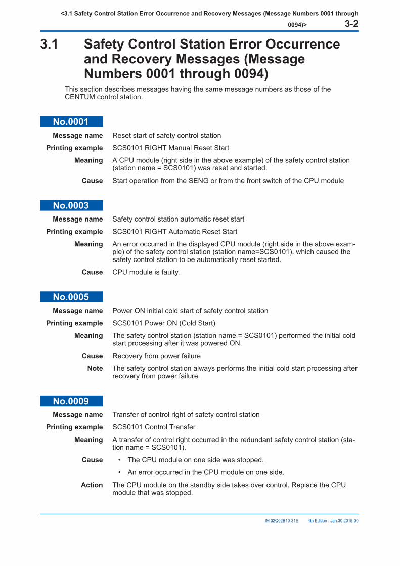
3.1 Safety Control Station Error Occurrenceand Recovery Messages (MessageNumbers 0001 through 0094)
This section describes messages having the same message numbers as those of theCENTUM control station.
No.0001Message name Reset start of safety control station
Printing example SCS0101 RIGHT Manual Reset Start
Meaning A CPU module (right side in the above example) of the safety control station(station name = SCS0101) was reset and started.
Cause Start operation from the SENG or from the front switch of the CPU module
No.0003Message name Safety control station automatic reset start
Printing example SCS0101 RIGHT Automatic Reset Start
Meaning An error occurred in the displayed CPU module (right side in the above exam-ple) of the safety control station (station name=SCS0101), which caused thesafety control station to be automatically reset started.
Cause CPU module is faulty.
No.0005Message name Power ON initial cold start of safety control station
Printing example SCS0101 Power ON (Cold Start)
Meaning The safety control station (station name = SCS0101) performed the initial coldstart processing after it was powered ON.
Cause Recovery from power failure
Note The safety control station always performs the initial cold start processing afterrecovery from power failure.
No.0009Message name Transfer of control right of safety control station
Printing example SCS0101 Control Transfer
Meaning A transfer of control right occurred in the redundant safety control station (sta-tion name = SCS0101).
Cause • The CPU module on one side was stopped.
• An error occurred in the CPU module on one side.
Action The CPU module on the standby side takes over control. Replace the CPUmodule that was stopped.
<3.1 Safety Control Station Error Occurrence and Recovery Messages (Message Numbers 0001 through
0094)> 3-2
IM 32Q02B10-31E 4th Edition : Jan.30,2015-00

No.0011Message name Fail information of safety control station
Printing example SCS0101 RIGHT Fail (xxxxxxxx Code= yyyy yyyy yyyy yyyy)
Meaning A CPU module (right side in the above example) of the safety control station(station name = SCS0101) failed.
Cause The causes are indicated by “causes (xxxxxxxx)” and a code. For more infor-mation, see the following table.
Table 3.1-1 Message No. 0011 - Cause List
Item Causesxxxxxxxx
Code (hex 16 digits)yyyy yyyy yyyy yyyy Description Auto re-
start
CPUmodulestop
SW STOP
-
Stop by operation of the front switch ofthe CPU module No
V STOP Stop instruction via control bus No
DC STOP Stop due to power failure No
CPUDOWN
NSR3(*1)An error occurred during CPU module er-ror check.NSR3, INTSTS, ERRSTS1 andERRSTS2 are detailed error codes.
YesINTSTS(*1)
ERRSTS1(*1)
ERRSTS2(*1)
SELF-STOP
(*2)
Stop after software detected an error No
UN-KNOWN Stop due to unknown cause No
RESTART Restart after software detected an error Yes
*1: If this error message is displayed, report the display contents of causes (xxxxxxxx) and code to Yokogawa’s service depart-ment.
*2: Refer to the following “Table 2.1-4 Error Codes and Solutions.”
Table 3.1-2 Error Codes and SolutionsCode (hex; 16 digits) Error Solution
0000 5090 yyyy yyyy Zero division occurred when runningthe application logic.
Check to see if the application logic con-tains zero division or not, and correct theapplication logic if it contains.
0000 5091 yyyy yyyyThe application logic is trying to ac-cess an array datum beyond thescope of the array.
Check the application and find out whichlogic program is accessing the out-of-rangearray data and correct the error.
0000 50a9 yyyy yyyy
The database inconsistence is de-tected. It may be caused by restart-ing the SCS without releasing thebrake point.
Run offline downloading.
4000 3BF1 0255 8082(*1)
The firmware (Revision F4) in theCPU module is too old to support thesystem with Optical ESB Bus Re-peater modules.
For a system that contains Optical ESBBus Repeater modules, the firmware ofCPU with the proper revision numbershould be used.
4000 3BF1 xxxx xxxx
An error has been detected in theI/O unit of the CPU module.SCSV1-S : There may be a failure inthe I/O unit of the CPU module.SCSP2-S: There may be a failure inthe I/O unit of the CPU module orthe I/O communication is posingheavy load on the CPU.
If one of the redundant CPU modules hasstopped, message No. 0787 is generatedat the same time.Refer to the explanation of message No.0787.
Continues on the next page
<3.1 Safety Control Station Error Occurrence and Recovery Messages (Message Numbers 0001 through
0094)> 3-3
IM 32Q02B10-31E 4th Edition : Jan.30,2015-00
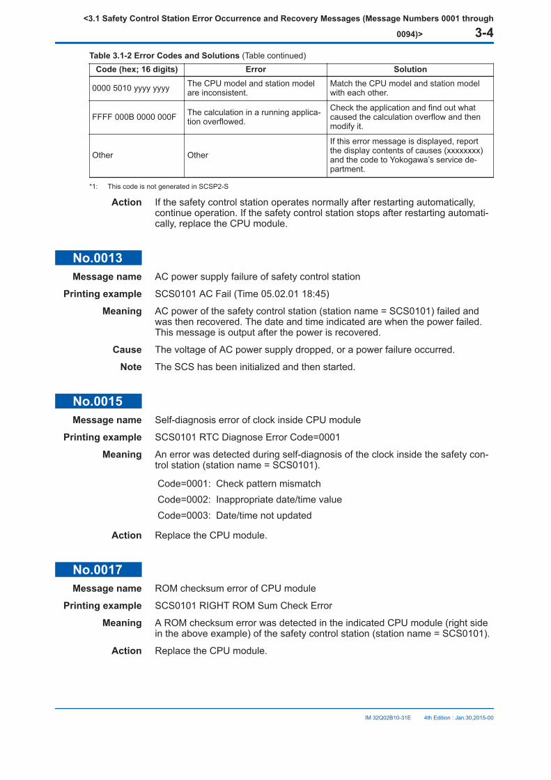
Table 3.1-2 Error Codes and Solutions (Table continued)Code (hex; 16 digits) Error Solution
0000 5010 yyyy yyyy The CPU model and station modelare inconsistent.
Match the CPU model and station modelwith each other.
FFFF 000B 0000 000F The calculation in a running applica-tion overflowed.
Check the application and find out whatcaused the calculation overflow and thenmodify it.
Other Other
If this error message is displayed, reportthe display contents of causes (xxxxxxxx)and the code to Yokogawa’s service de-partment.
*1: This code is not generated in SCSP2-S
Action If the safety control station operates normally after restarting automatically,continue operation. If the safety control station stops after restarting automati-cally, replace the CPU module.
No.0013Message name AC power supply failure of safety control station
Printing example SCS0101 AC Fail (Time 05.02.01 18:45)
Meaning AC power of the safety control station (station name = SCS0101) failed andwas then recovered. The date and time indicated are when the power failed.This message is output after the power is recovered.
Cause The voltage of AC power supply dropped, or a power failure occurred.
Note The SCS has been initialized and then started.
No.0015Message name Self-diagnosis error of clock inside CPU module
Printing example SCS0101 RTC Diagnose Error Code=0001
Meaning An error was detected during self-diagnosis of the clock inside the safety con-trol station (station name = SCS0101).
Code=0001: Check pattern mismatchCode=0002: Inappropriate date/time valueCode=0003: Date/time not updated
Action Replace the CPU module.
No.0017Message name ROM checksum error of CPU module
Printing example SCS0101 RIGHT ROM Sum Check Error
Meaning A ROM checksum error was detected in the indicated CPU module (right sidein the above example) of the safety control station (station name = SCS0101).
Action Replace the CPU module.
<3.1 Safety Control Station Error Occurrence and Recovery Messages (Message Numbers 0001 through
0094)> 3-4
IM 32Q02B10-31E 4th Edition : Jan.30,2015-00
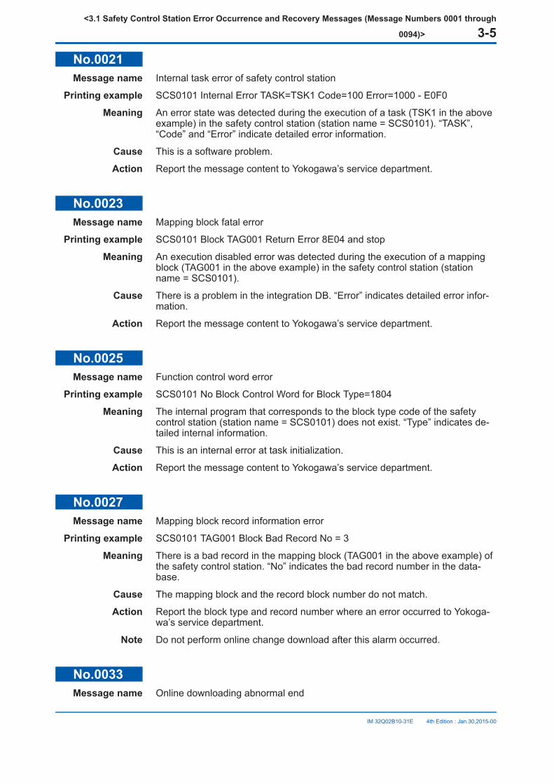
No.0021Message name Internal task error of safety control station
Printing example SCS0101 Internal Error TASK=TSK1 Code=100 Error=1000 - E0F0
Meaning An error state was detected during the execution of a task (TSK1 in the aboveexample) in the safety control station (station name = SCS0101). “TASK”,“Code” and “Error” indicate detailed error information.
Cause This is a software problem.
Action Report the message content to Yokogawa’s service department.
No.0023Message name Mapping block fatal error
Printing example SCS0101 Block TAG001 Return Error 8E04 and stop
Meaning An execution disabled error was detected during the execution of a mappingblock (TAG001 in the above example) in the safety control station (stationname = SCS0101).
Cause There is a problem in the integration DB. “Error” indicates detailed error infor-mation.
Action Report the message content to Yokogawa’s service department.
No.0025Message name Function control word error
Printing example SCS0101 No Block Control Word for Block Type=1804
Meaning The internal program that corresponds to the block type code of the safetycontrol station (station name = SCS0101) does not exist. “Type” indicates de-tailed internal information.
Cause This is an internal error at task initialization.
Action Report the message content to Yokogawa’s service department.
No.0027Message name Mapping block record information error
Printing example SCS0101 TAG001 Block Bad Record No = 3
Meaning There is a bad record in the mapping block (TAG001 in the above example) ofthe safety control station. “No” indicates the bad record number in the data-base.
Cause The mapping block and the record block number do not match.
Action Report the block type and record number where an error occurred to Yokoga-wa’s service department.
Note Do not perform online change download after this alarm occurred.
No.0033Message name Online downloading abnormal end
<3.1 Safety Control Station Error Occurrence and Recovery Messages (Message Numbers 0001 through
0094)> 3-5
IM 32Q02B10-31E 4th Edition : Jan.30,2015-00
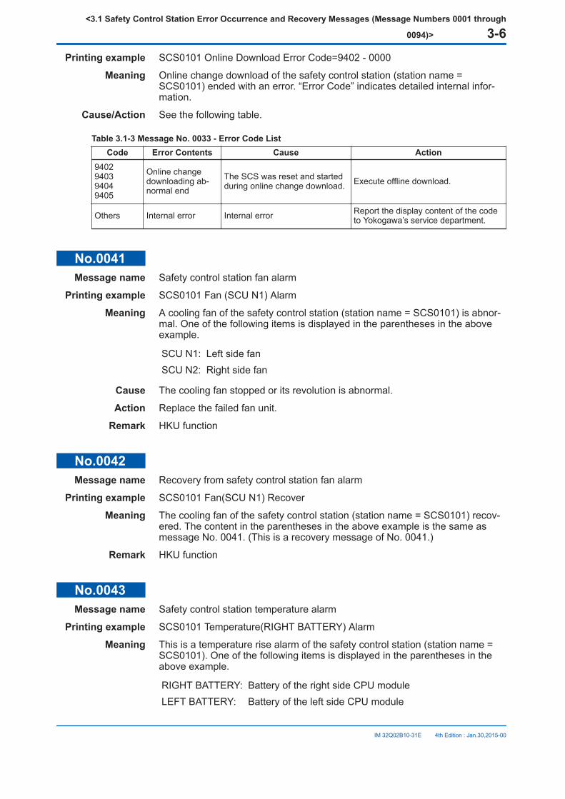
Printing example SCS0101 Online Download Error Code=9402 - 0000
Meaning Online change download of the safety control station (station name =SCS0101) ended with an error. “Error Code” indicates detailed internal infor-mation.
Cause/Action See the following table.
Table 3.1-3 Message No. 0033 - Error Code ListCode Error Contents Cause Action
9402940394049405
Online changedownloading ab-normal end
The SCS was reset and startedduring online change download. Execute offline download.
Others Internal error Internal error Report the display content of the codeto Yokogawa’s service department.
No.0041Message name Safety control station fan alarm
Printing example SCS0101 Fan (SCU N1) Alarm
Meaning A cooling fan of the safety control station (station name = SCS0101) is abnor-mal. One of the following items is displayed in the parentheses in the aboveexample.
SCU N1: Left side fanSCU N2: Right side fan
Cause The cooling fan stopped or its revolution is abnormal.
Action Replace the failed fan unit.
Remark HKU function
No.0042Message name Recovery from safety control station fan alarm
Printing example SCS0101 Fan(SCU N1) Recover
Meaning The cooling fan of the safety control station (station name = SCS0101) recov-ered. The content in the parentheses in the above example is the same asmessage No. 0041. (This is a recovery message of No. 0041.)
Remark HKU function
No.0043Message name Safety control station temperature alarm
Printing example SCS0101 Temperature(RIGHT BATTERY) Alarm
Meaning This is a temperature rise alarm of the safety control station (station name =SCS0101). One of the following items is displayed in the parentheses in theabove example.
RIGHT BATTERY: Battery of the right side CPU moduleLEFT BATTERY: Battery of the left side CPU module
<3.1 Safety Control Station Error Occurrence and Recovery Messages (Message Numbers 0001 through
0094)> 3-6
IM 32Q02B10-31E 4th Edition : Jan.30,2015-00

AIR IN: Air inletAIR OUT: Air outlet
Cause The CPU module temperature exceeded the specified value.
Action After checking the operation of the cooling fans, report to Yokogawa’s servicedepartment as necessary.
Remark HKU function
No.0044Message name Recovery from safety control station temperature alarm
Printing example SCS0101 Temperature(RIGHT BATTERY) Recover
Meaning The temperature of the safety control station (station name = SCS0101) recov-ered normally. The content in the parentheses in the above example is thesame as message No. 0043. (This is a recovery message of No. 0043.)
Remark HKU function
No.0045Message name Power supply module alarm of safety control station
Printing example SCS0101 RIGHT PSU Alarm
Meaning The power supply module of a CPU node (right side in the above example) ofthe safety control station (station name = SCS0101) is abnormal.
Cause Power supply module failure
Action Replace the applicable power supply module.
No.0046Message name Recovery from power supply module alarm of safety control station
Printing example SCS0101 RIGHT PSU Recover
Meaning The power supply module of a CPU node (right side in the above example) ofthe safety control station (station name = SCS0101) recovered normally. (Thisis a recovery message of No. 0045.)
No.0047Message name Battery alarm of CPU module
Printing example SCS0101 RIGHT Battery Alarm
Meaning A battery of the CPU module (right side in the above example) of the safetycontrol station (station name = SCS0101) is abnormal.
Cause The battery switch is OFF, or the battery is faulty.
Action Make sure that the switch of the applicable battery is ON. If the above mes-sage occurs even if the battery switch is ON, replace the battery.
Remark HKU function
<3.1 Safety Control Station Error Occurrence and Recovery Messages (Message Numbers 0001 through
0094)> 3-7
IM 32Q02B10-31E 4th Edition : Jan.30,2015-00
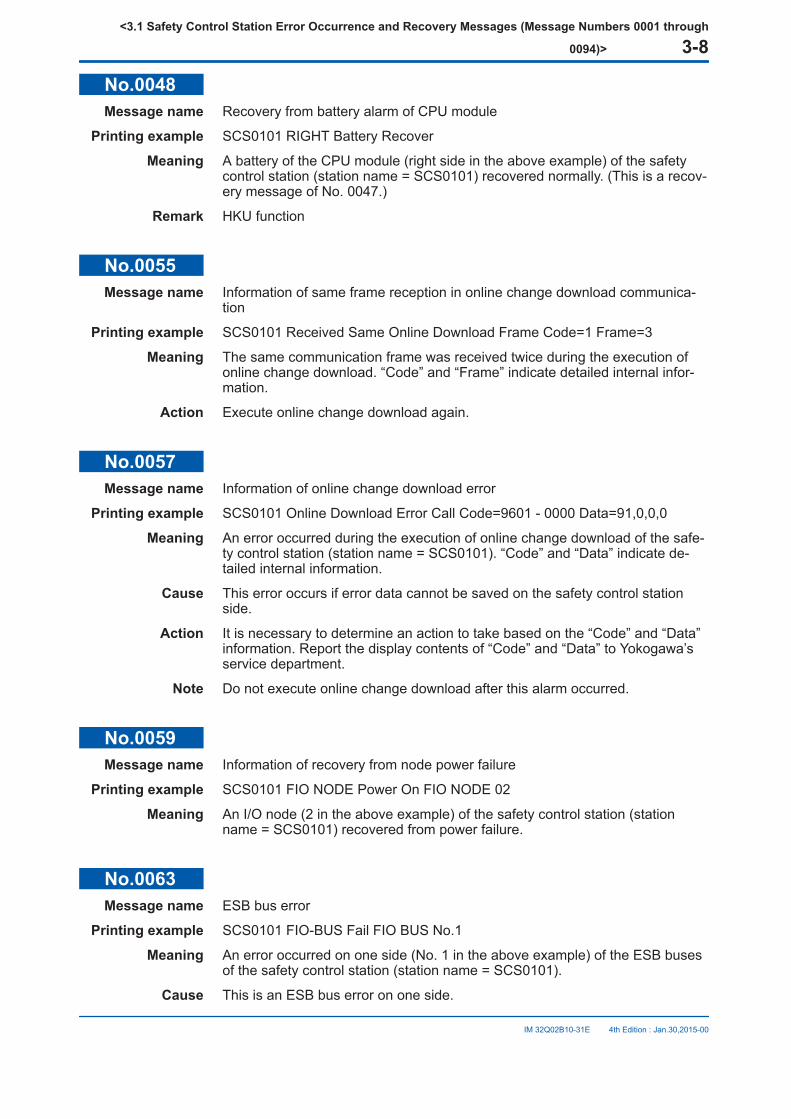
No.0048Message name Recovery from battery alarm of CPU module
Printing example SCS0101 RIGHT Battery Recover
Meaning A battery of the CPU module (right side in the above example) of the safetycontrol station (station name = SCS0101) recovered normally. (This is a recov-ery message of No. 0047.)
Remark HKU function
No.0055Message name Information of same frame reception in online change download communica-
tion
Printing example SCS0101 Received Same Online Download Frame Code=1 Frame=3
Meaning The same communication frame was received twice during the execution ofonline change download. “Code” and “Frame” indicate detailed internal infor-mation.
Action Execute online change download again.
No.0057Message name Information of online change download error
Printing example SCS0101 Online Download Error Call Code=9601 - 0000 Data=91,0,0,0
Meaning An error occurred during the execution of online change download of the safe-ty control station (station name = SCS0101). “Code” and “Data” indicate de-tailed internal information.
Cause This error occurs if error data cannot be saved on the safety control stationside.
Action It is necessary to determine an action to take based on the “Code” and “Data”information. Report the display contents of “Code” and “Data” to Yokogawa’sservice department.
Note Do not execute online change download after this alarm occurred.
No.0059Message name Information of recovery from node power failure
Printing example SCS0101 FIO NODE Power On FIO NODE 02
Meaning An I/O node (2 in the above example) of the safety control station (stationname = SCS0101) recovered from power failure.
No.0063Message name ESB bus error
Printing example SCS0101 FIO-BUS Fail FIO BUS No.1
Meaning An error occurred on one side (No. 1 in the above example) of the ESB busesof the safety control station (station name = SCS0101).
Cause This is an ESB bus error on one side.
<3.1 Safety Control Station Error Occurrence and Recovery Messages (Message Numbers 0001 through
0094)> 3-8
IM 32Q02B10-31E 4th Edition : Jan.30,2015-00
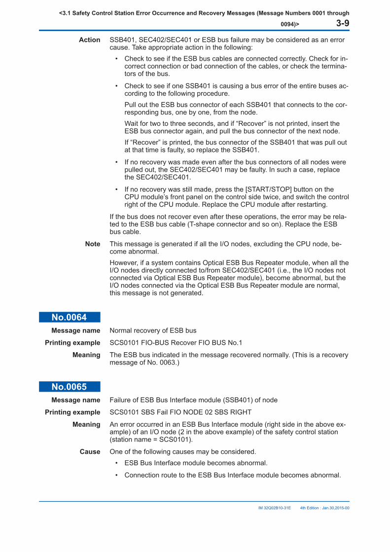
Action SSB401, SEC402/SEC401 or ESB bus failure may be considered as an errorcause. Take appropriate action in the following:
• Check to see if the ESB bus cables are connected correctly. Check for in-correct connection or bad connection of the cables, or check the termina-tors of the bus.
• Check to see if one SSB401 is causing a bus error of the entire buses ac-cording to the following procedure.Pull out the ESB bus connector of each SSB401 that connects to the cor-responding bus, one by one, from the node.Wait for two to three seconds, and if “Recover” is not printed, insert theESB bus connector again, and pull the bus connector of the next node.If “Recover” is printed, the bus connector of the SSB401 that was pull outat that time is faulty, so replace the SSB401.
• If no recovery was made even after the bus connectors of all nodes werepulled out, the SEC402/SEC401 may be faulty. In such a case, replacethe SEC402/SEC401.
• If no recovery was still made, press the [START/STOP] button on theCPU module’s front panel on the control side twice, and switch the controlright of the CPU module. Replace the CPU module after restarting.
If the bus does not recover even after these operations, the error may be rela-ted to the ESB bus cable (T-shape connector and so on). Replace the ESBbus cable.
Note This message is generated if all the I/O nodes, excluding the CPU node, be-come abnormal.However, if a system contains Optical ESB Bus Repeater module, when all theI/O nodes directly connected to/from SEC402/SEC401 (i.e., the I/O nodes notconnected via Optical ESB Bus Repeater module), become abnormal, but theI/O nodes connected via the Optical ESB Bus Repeater module are normal,this message is not generated.
No.0064Message name Normal recovery of ESB bus
Printing example SCS0101 FIO-BUS Recover FIO BUS No.1
Meaning The ESB bus indicated in the message recovered normally. (This is a recoverymessage of No. 0063.)
No.0065Message name Failure of ESB Bus Interface module (SSB401) of node
Printing example SCS0101 SBS Fail FIO NODE 02 SBS RIGHT
Meaning An error occurred in an ESB Bus Interface module (right side in the above ex-ample) of an I/O node (2 in the above example) of the safety control station(station name = SCS0101).
Cause One of the following causes may be considered.• ESB Bus Interface module becomes abnormal.
• Connection route to the ESB Bus Interface module becomes abnormal.
<3.1 Safety Control Station Error Occurrence and Recovery Messages (Message Numbers 0001 through
0094)> 3-9
IM 32Q02B10-31E 4th Edition : Jan.30,2015-00
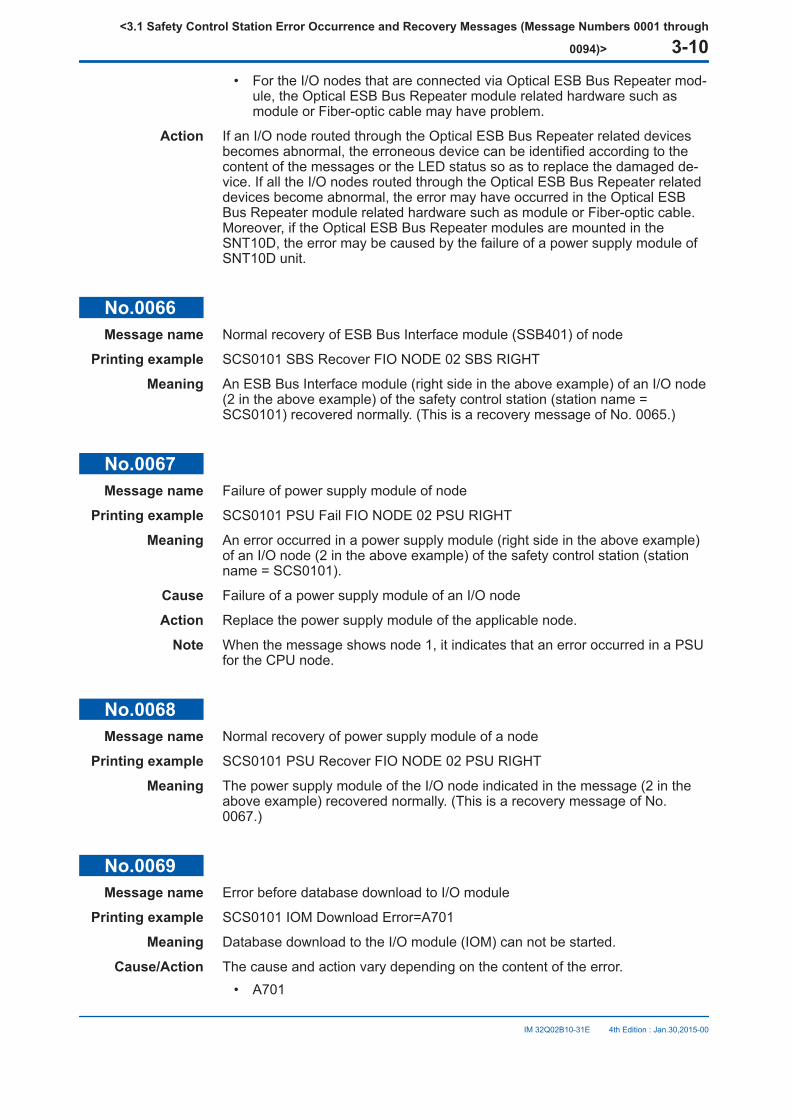
• For the I/O nodes that are connected via Optical ESB Bus Repeater mod-ule, the Optical ESB Bus Repeater module related hardware such asmodule or Fiber-optic cable may have problem.
Action If an I/O node routed through the Optical ESB Bus Repeater related devicesbecomes abnormal, the erroneous device can be identified according to thecontent of the messages or the LED status so as to replace the damaged de-vice. If all the I/O nodes routed through the Optical ESB Bus Repeater relateddevices become abnormal, the error may have occurred in the Optical ESBBus Repeater module related hardware such as module or Fiber-optic cable.Moreover, if the Optical ESB Bus Repeater modules are mounted in theSNT10D, the error may be caused by the failure of a power supply module ofSNT10D unit.
No.0066Message name Normal recovery of ESB Bus Interface module (SSB401) of node
Printing example SCS0101 SBS Recover FIO NODE 02 SBS RIGHT
Meaning An ESB Bus Interface module (right side in the above example) of an I/O node(2 in the above example) of the safety control station (station name =SCS0101) recovered normally. (This is a recovery message of No. 0065.)
No.0067Message name Failure of power supply module of node
Printing example SCS0101 PSU Fail FIO NODE 02 PSU RIGHT
Meaning An error occurred in a power supply module (right side in the above example)of an I/O node (2 in the above example) of the safety control station (stationname = SCS0101).
Cause Failure of a power supply module of an I/O node
Action Replace the power supply module of the applicable node.
Note When the message shows node 1, it indicates that an error occurred in a PSUfor the CPU node.
No.0068Message name Normal recovery of power supply module of a node
Printing example SCS0101 PSU Recover FIO NODE 02 PSU RIGHT
Meaning The power supply module of the I/O node indicated in the message (2 in theabove example) recovered normally. (This is a recovery message of No.0067.)
No.0069Message name Error before database download to I/O module
Printing example SCS0101 IOM Download Error=A701
Meaning Database download to the I/O module (IOM) can not be started.
Cause/Action The cause and action vary depending on the content of the error.• A701
<3.1 Safety Control Station Error Occurrence and Recovery Messages (Message Numbers 0001 through
0094)> 3-10
IM 32Q02B10-31E 4th Edition : Jan.30,2015-00
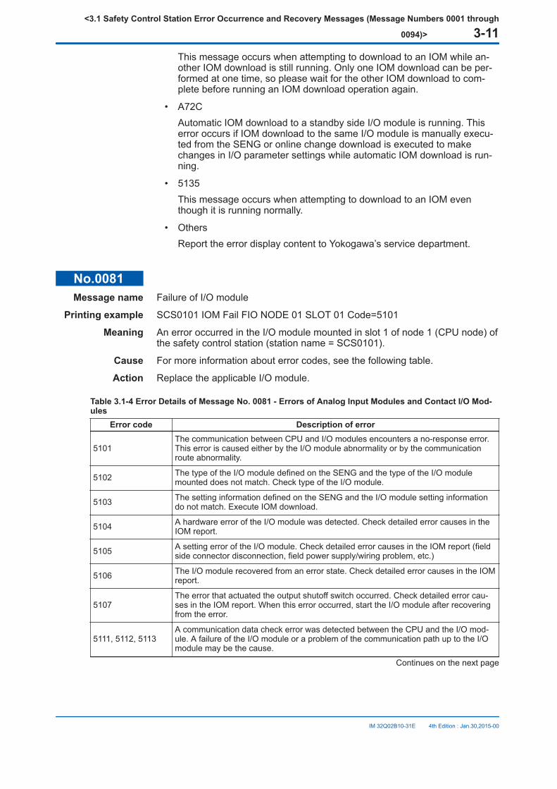
This message occurs when attempting to download to an IOM while an-other IOM download is still running. Only one IOM download can be per-formed at one time, so please wait for the other IOM download to com-plete before running an IOM download operation again.
• A72CAutomatic IOM download to a standby side I/O module is running. Thiserror occurs if IOM download to the same I/O module is manually execu-ted from the SENG or online change download is executed to makechanges in I/O parameter settings while automatic IOM download is run-ning.
• 5135This message occurs when attempting to download to an IOM eventhough it is running normally.
• OthersReport the error display content to Yokogawa’s service department.
No.0081Message name Failure of I/O module
Printing example SCS0101 IOM Fail FIO NODE 01 SLOT 01 Code=5101
Meaning An error occurred in the I/O module mounted in slot 1 of node 1 (CPU node) ofthe safety control station (station name = SCS0101).
Cause For more information about error codes, see the following table.
Action Replace the applicable I/O module.
Table 3.1-4 Error Details of Message No. 0081 - Errors of Analog Input Modules and Contact I/O Mod-ules
Error code Description of error
5101The communication between CPU and I/O modules encounters a no-response error.This error is caused either by the I/O module abnormality or by the communicationroute abnormality.
5102 The type of the I/O module defined on the SENG and the type of the I/O modulemounted does not match. Check type of the I/O module.
5103 The setting information defined on the SENG and the I/O module setting informationdo not match. Execute IOM download.
5104 A hardware error of the I/O module was detected. Check detailed error causes in theIOM report.
5105 A setting error of the I/O module. Check detailed error causes in the IOM report (fieldside connector disconnection, field power supply/wiring problem, etc.)
5106 The I/O module recovered from an error state. Check detailed error causes in the IOMreport.
5107The error that actuated the output shutoff switch occurred. Check detailed error cau-ses in the IOM report. When this error occurred, start the I/O module after recoveringfrom the error.
5111, 5112, 5113A communication data check error was detected between the CPU and the I/O mod-ule. A failure of the I/O module or a problem of the communication path up to the I/Omodule may be the cause.
Continues on the next page
<3.1 Safety Control Station Error Occurrence and Recovery Messages (Message Numbers 0001 through
0094)> 3-11
IM 32Q02B10-31E 4th Edition : Jan.30,2015-00
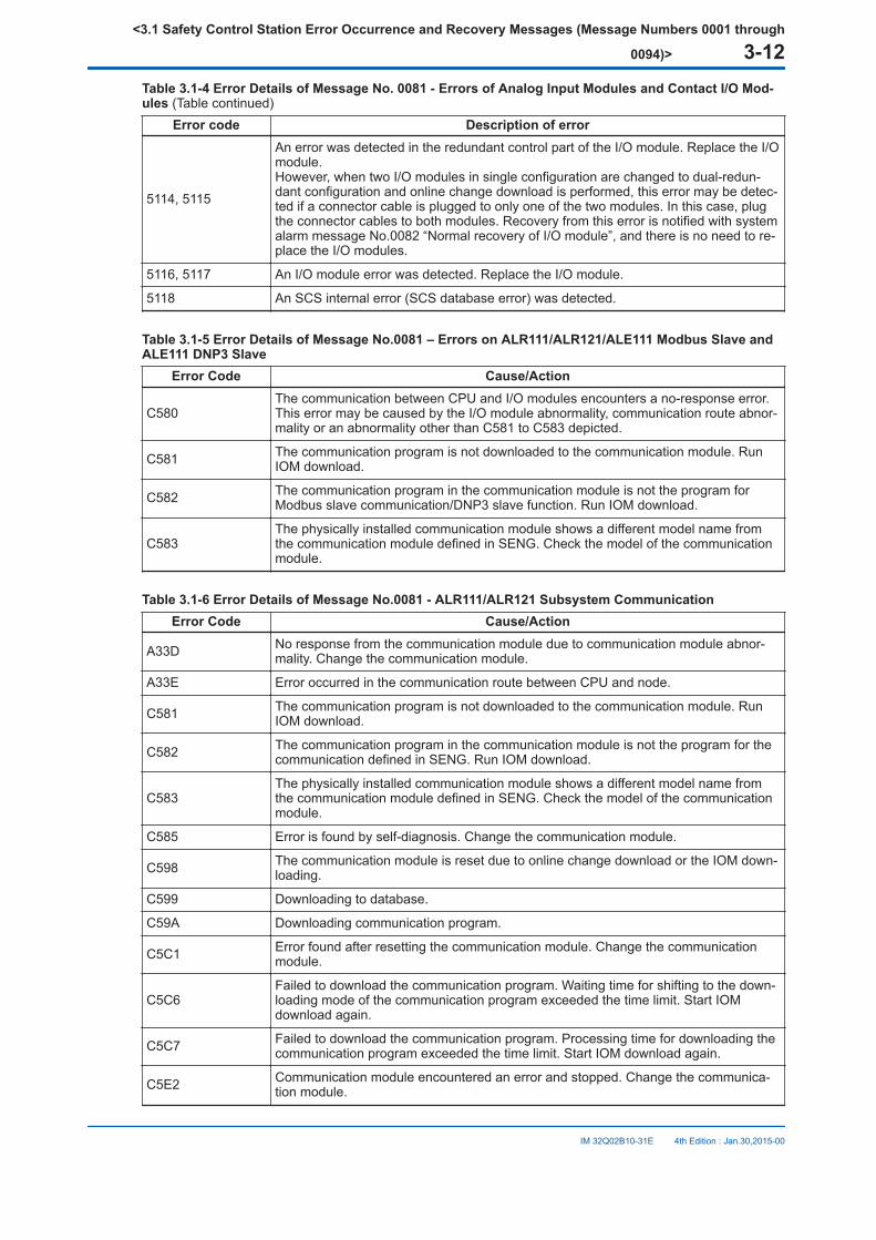
Table 3.1-4 Error Details of Message No. 0081 - Errors of Analog Input Modules and Contact I/O Mod-ules (Table continued)
Error code Description of error
5114, 5115
An error was detected in the redundant control part of the I/O module. Replace the I/Omodule.However, when two I/O modules in single configuration are changed to dual-redun-dant configuration and online change download is performed, this error may be detec-ted if a connector cable is plugged to only one of the two modules. In this case, plugthe connector cables to both modules. Recovery from this error is notified with systemalarm message No.0082 “Normal recovery of I/O module”, and there is no need to re-place the I/O modules.
5116, 5117 An I/O module error was detected. Replace the I/O module.
5118 An SCS internal error (SCS database error) was detected.
Table 3.1-5 Error Details of Message No.0081 – Errors on ALR111/ALR121/ALE111 Modbus Slave andALE111 DNP3 Slave
Error Code Cause/Action
C580The communication between CPU and I/O modules encounters a no-response error.This error may be caused by the I/O module abnormality, communication route abnor-mality or an abnormality other than C581 to C583 depicted.
C581 The communication program is not downloaded to the communication module. RunIOM download.
C582 The communication program in the communication module is not the program forModbus slave communication/DNP3 slave function. Run IOM download.
C583The physically installed communication module shows a different model name fromthe communication module defined in SENG. Check the model of the communicationmodule.
Table 3.1-6 Error Details of Message No.0081 - ALR111/ALR121 Subsystem CommunicationError Code Cause/Action
A33D No response from the communication module due to communication module abnor-mality. Change the communication module.
A33E Error occurred in the communication route between CPU and node.
C581 The communication program is not downloaded to the communication module. RunIOM download.
C582 The communication program in the communication module is not the program for thecommunication defined in SENG. Run IOM download.
C583The physically installed communication module shows a different model name fromthe communication module defined in SENG. Check the model of the communicationmodule.
C585 Error is found by self-diagnosis. Change the communication module.
C598 The communication module is reset due to online change download or the IOM down-loading.
C599 Downloading to database.
C59A Downloading communication program.
C5C1 Error found after resetting the communication module. Change the communicationmodule.
C5C6Failed to download the communication program. Waiting time for shifting to the down-loading mode of the communication program exceeded the time limit. Start IOMdownload again.
C5C7 Failed to download the communication program. Processing time for downloading thecommunication program exceeded the time limit. Start IOM download again.
C5E2 Communication module encountered an error and stopped. Change the communica-tion module.
<3.1 Safety Control Station Error Occurrence and Recovery Messages (Message Numbers 0001 through
0094)> 3-12
IM 32Q02B10-31E 4th Edition : Jan.30,2015-00
No.0082Message name Normal recovery of I/O module
Printing example SCS0101 IOM Recover FIO NODE 01 SLOT 01
Meaning The I/O module mounted in slot 1 of node 1 in the safety control station (sta-tion name = SCS0101) recovered normally. (This is a recovery message ofNo. 0081.)
No.0083Message name I/O module database error occurred
Printing example SCS0101 IOM Configuration Error FIO NODE 01 SLOT 01
Meaning An error occurred in the database on the I/O module mounted in slot 1 of node1 in the safety control station (station name = SCS0101).
Cause The database on the I/O module and the database on the SCS do not match.The following causes may be considered.
• IOM download has not been executed.
• IOM failure.
Action If this error occurred after replacing a module or at startup, the database mightnot have been downloaded to the I/O module. Execute IOM download.If this error occurred during I/O module operation, the I/O module may be faul-ty. Replace the I/O module.
No.0085Message name I/O module communication error occurred
Printing example SCS0101 IOM Communication Error FIO NODE 01 SLOT 01 RIGHT
Meaning An error occurred in one of the SB buses (right side in the above example). Anerror occurred when accessing the I/O module mounted in slot 1 of node 1 inthe safety control station (station name = SCS0101).
Cause If this error occurred on all input modules within the same node, an I/O modulemay be faulty, or the backboard bus of the node may be faulty. Or, an ESB bus(right side in the above example) or an SSB401 (right side in the above exam-ple) may be faulty, or they may not be connected properly.
Action Report to Yokogawa’s service department.
No.0086Message name Recovery from I/O module communication error
Printing example SCS0101 IOM Communication Recover FIO NODE 01 SLOT 01 RIGHT
Meaning A communication error with the I/O module mounted in slot 1 of node 1 in thesafety control station (station name = SCS0101) recovered. (This is a recoverymessage of No. 0085.)
No.0087Message name Node error occurred
<3.1 Safety Control Station Error Occurrence and Recovery Messages (Message Numbers 0001 through
0094)> 3-13
IM 32Q02B10-31E 4th Edition : Jan.30,2015-00

Printing example SCS0101 NODE Fail FIO NODE 02
Meaning An error occurred in node 2 of the safety control station (station name =SCS0101).
Cause One of the following causes may be considered.• A power failure occurred in the node, or both of the two ESB buses are
abnormal.
• Both SSB401 are abnormal.
• For the I/O nodes that connected via Optical ESB Bus Repeater module,the Optical ESB Bus Repeater module related hardware such as moduleor Fiber-optic cable may have problem.
Action Report to Yokogawa’s service department.
No.0088Message name Normal recovery of node
Printing example SCS0101 NODE Recover FIO NODE 02
Meaning The node indicated in the message recovered normally. (This is a recoverymessage of No. 0087.)
No.0089Message name Subsystem communication error
Printing example SCS0101 SS-COM Error FIO NODE 01 SLOT 01 PORT 01 STN001 Code=A3B0
Meaning A communication error occurred between the indicated communication moduleand the subsystem.
Cause/Action The error details can be found in the instruction manuals of the connectedsubsystem. See the manuals for error details.The error codes that irrelevant to the connected subsystems are shown.
Table 3.1-7 Error Details of Message No.0089 - Errors that irrelevant to subsystemsCode Error Cause/Action
A391 Driver Busy Occurs when sending or receiving.
A392 Communication Line BusyThis message occurs when carrier detection fails due to theCD line is energized within the transmission enable monitor-ing time.(*1)
A393 Communication Line Not Ready
This message occurs when clear to send fails due to the CSline is not energized within the transmission enable monitor-ing time, or when data ready fails due to the DR line is notenergized within the transmission enable monitoring time.(*1)
A394 Data size is too large for send-ing.
A395 The port for sending is not de-clared.
A397 Underrun
A398 Interval of characters becametimeout
This message occurs when the interval of characters ex-ceeds the specified time.
Continues on the next page
<3.1 Safety Control Station Error Occurrence and Recovery Messages (Message Numbers 0001 through
0094)> 3-14
IM 32Q02B10-31E 4th Edition : Jan.30,2015-00
Table 3.1-7 Error Details of Message No.0089 - Errors that irrelevant to subsystems (Table continued)Code Error Cause/Action
A399 Reception buffer overflow
A39A Reception parity error
A39B Reception overrun
A39C Reception frame error
A39D Number of characters beyondrange
A39F Other errors
A3B0 toA3FF Reserved for subsystems For more information, see the instruction manuals of sub-
systems.
*1: The transmission-watching timer monitors the waiting time of the transmission line become ready for transmission. When RSis sent, and the waiting time for transmission exceeds the specified time period, the transmission becomes error. The trans-mission waiting time is normally set to 1000 ms.The conditions for transmission are as follows:• CD line off (When CD check is enabled)• CS (CTS) line on• DR line on (When DR check is enabled)
Remark Subsystem communication
No.0090Message name Subsystem communication recovered
Printing example SCS0101 SS-COM Recover FIO NODE 01 SLOT 01 PORT 01 STN001
Meaning The communication between the indicated communication module and thesubsystem recovered from the error.
Remark Subsystem communication
No.0093Message name CPU node’s housekeeping unit error
Printing example SCS0101 RIGHT HKU Error Code=0001
Meaning The CPU node’s housekeeping unit of the safety control station (station name= SCS0101) is faulty. “Code” indicates detailed internal information.
Action Report to Yokogawa’s service department.
Remark HKU function
No.0094Message name Normal recovery of CPU node’s housekeeping unit
Printing example SCS0101 RIGHT HKU Recover Code=0001
Meaning The CPU node’s housekeeping unit of the safety control station (station name= SCS0101) recovered normally. (This is a recovery message of No. 0093.)
Remark HKU function
<3.1 Safety Control Station Error Occurrence and Recovery Messages (Message Numbers 0001 through
0094)> 3-15
IM 32Q02B10-31E 4th Edition : Jan.30,2015-00
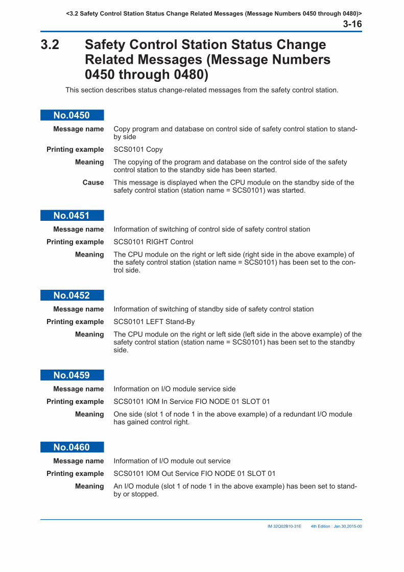
3.2 Safety Control Station Status ChangeRelated Messages (Message Numbers0450 through 0480)
This section describes status change-related messages from the safety control station.
No.0450Message name Copy program and database on control side of safety control station to stand-
by side
Printing example SCS0101 Copy
Meaning The copying of the program and database on the control side of the safetycontrol station to the standby side has been started.
Cause This message is displayed when the CPU module on the standby side of thesafety control station (station name = SCS0101) was started.
No.0451Message name Information of switching of control side of safety control station
Printing example SCS0101 RIGHT Control
Meaning The CPU module on the right or left side (right side in the above example) ofthe safety control station (station name = SCS0101) has been set to the con-trol side.
No.0452Message name Information of switching of standby side of safety control station
Printing example SCS0101 LEFT Stand-By
Meaning The CPU module on the right or left side (left side in the above example) of thesafety control station (station name = SCS0101) has been set to the standbyside.
No.0459Message name Information on I/O module service side
Printing example SCS0101 IOM In Service FIO NODE 01 SLOT 01
Meaning One side (slot 1 of node 1 in the above example) of a redundant I/O modulehas gained control right.
No.0460Message name Information of I/O module out service
Printing example SCS0101 IOM Out Service FIO NODE 01 SLOT 01
Meaning An I/O module (slot 1 of node 1 in the above example) has been set to stand-by or stopped.
<3.2 Safety Control Station Status Change Related Messages (Message Numbers 0450 through 0480)>
3-16
IM 32Q02B10-31E 4th Edition : Jan.30,2015-00
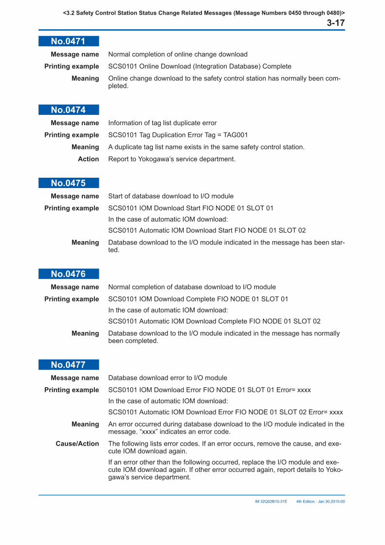
No.0471Message name Normal completion of online change download
Printing example SCS0101 Online Download (Integration Database) Complete
Meaning Online change download to the safety control station has normally been com-pleted.
No.0474Message name Information of tag list duplicate error
Printing example SCS0101 Tag Duplication Error Tag = TAG001
Meaning A duplicate tag list name exists in the same safety control station.
Action Report to Yokogawa’s service department.
No.0475Message name Start of database download to I/O module
Printing example SCS0101 IOM Download Start FIO NODE 01 SLOT 01In the case of automatic IOM download:SCS0101 Automatic IOM Download Start FIO NODE 01 SLOT 02
Meaning Database download to the I/O module indicated in the message has been star-ted.
No.0476Message name Normal completion of database download to I/O module
Printing example SCS0101 IOM Download Complete FIO NODE 01 SLOT 01In the case of automatic IOM download:SCS0101 Automatic IOM Download Complete FIO NODE 01 SLOT 02
Meaning Database download to the I/O module indicated in the message has normallybeen completed.
No.0477Message name Database download error to I/O module
Printing example SCS0101 IOM Download Error FIO NODE 01 SLOT 01 Error= xxxxIn the case of automatic IOM download:SCS0101 Automatic IOM Download Error FIO NODE 01 SLOT 02 Error= xxxx
Meaning An error occurred during database download to the I/O module indicated in themessage. “xxxx” indicates an error code.
Cause/Action The following lists error codes. If an error occurs, remove the cause, and exe-cute IOM download again.If an error other than the following occurred, replace the I/O module and exe-cute IOM download again. If other error occurred again, report details to Yoko-gawa’s service department.
<3.2 Safety Control Station Status Change Related Messages (Message Numbers 0450 through 0480)>
3-17
IM 32Q02B10-31E 4th Edition : Jan.30,2015-00
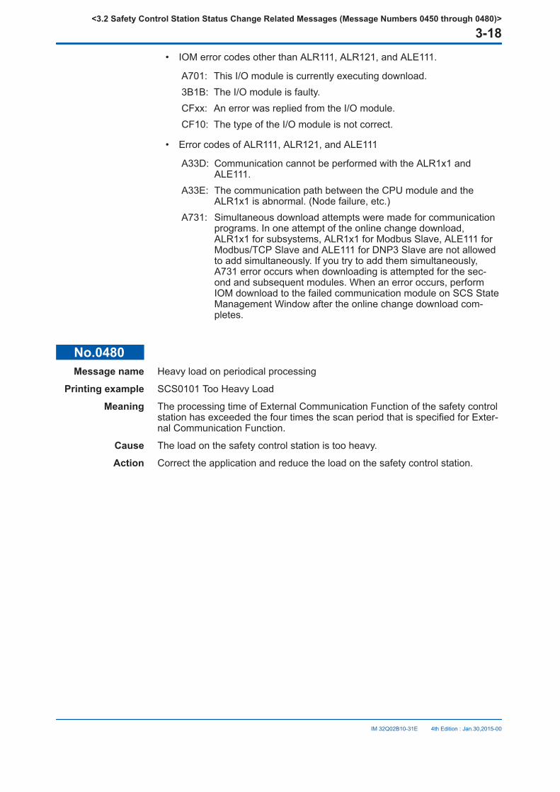
• IOM error codes other than ALR111, ALR121, and ALE111.
A701: This I/O module is currently executing download.3B1B: The I/O module is faulty.CFxx: An error was replied from the I/O module.CF10: The type of the I/O module is not correct.
• Error codes of ALR111, ALR121, and ALE111
A33D: Communication cannot be performed with the ALR1x1 andALE111.
A33E: The communication path between the CPU module and theALR1x1 is abnormal. (Node failure, etc.)
A731: Simultaneous download attempts were made for communicationprograms. In one attempt of the online change download,ALR1x1 for subsystems, ALR1x1 for Modbus Slave, ALE111 forModbus/TCP Slave and ALE111 for DNP3 Slave are not allowedto add simultaneously. If you try to add them simultaneously,A731 error occurs when downloading is attempted for the sec-ond and subsequent modules. When an error occurs, performIOM download to the failed communication module on SCS StateManagement Window after the online change download com-pletes.
No.0480Message name Heavy load on periodical processing
Printing example SCS0101 Too Heavy Load
Meaning The processing time of External Communication Function of the safety controlstation has exceeded the four times the scan period that is specified for Exter-nal Communication Function.
Cause The load on the safety control station is too heavy.
Action Correct the application and reduce the load on the safety control station.
<3.2 Safety Control Station Status Change Related Messages (Message Numbers 0450 through 0480)>
3-18
IM 32Q02B10-31E 4th Edition : Jan.30,2015-00
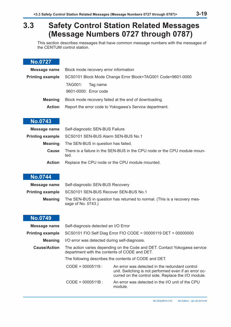
3.3 Safety Control Station Related Messages(Message Numbers 0727 through 0787)
This section describes messages that have common message numbers with the messages ofthe CENTUM control station.
No.0727Message name Block mode recovery error information
Printing example SCS0101 Block Mode Change Error Block=TAG001 Code=9601-0000
TAG001: Tag name9601-0000: Error code
Meaning Block mode recovery failed at the end of downloading.
Action Report the error code to Yokogawa’s Service department.
No.0743Message name Self-diagnostic SEN-BUS Failure
Printing example SCS0101 SEN-BUS Alarm SEN-BUS No.1
Meaning The SEN-BUS in question has failed.
Cause There is a failure in the SEN-BUS in the CPU node or the CPU module moun-ted.
Action Replace the CPU node or the CPU module mounted.
No.0744Message name Self-diagnostic SEN-BUS Recovery
Printing example SCS0101 SEN-BUS Recover SEN-BUS No.1
Meaning The SEN-BUS in question has returned to normal. (This is a recovery mes-sage of No. 0743.)
No.0749Message name Self-diagnosis detected an I/O Error
Printing example SCS0101 FIO Self Diag Error FIO CODE = 00005119 DET = 00000000
Meaning I/O error was detected during self-diagnosis.
Cause/Action The action varies depending on the Code and DET. Contact Yokogawa servicedepartment with the contents of CODE and DET.The following describes the contents of CODE and DET.
CODE = 00005119 : An error was detected in the redundant controlunit. Switching is not performed even if an error oc-curred on the control side. Replace the I/O module.
CODE = 0000511B : An error was detected in the I/O unit of the CPUmodule.
<3.3 Safety Control Station Related Messages (Message Numbers 0727 through 0787)> 3-19
IM 32Q02B10-31E 4th Edition : Jan.30,2015-00

DET = 0000 Y48x : A detail code of CODE = 0000511B. Y = 0 indi-cates an error in the right CPU module, and Y = 8indicates an error in the left CPU module.
No.0750Message name I/O Recovery from the error detected by self-diagnosis
Printing example SCS0101 FIO Self Diag Recover FIO CODE = 00000000 DET = 00000000
Meaning Recovery from I/O error detected by self-diagnosis. (This is a recovery mes-sage of No. 0749.)
No.0751Message name Time self-diagnostic testing error
Printing example SCS0101 RIGHT Time Self Diag Error Code=00030021
Meaning A clock error is detected by self-diagnosis while the CPU of either redundantor non-redundant is running.
Cause VEHICLE clock, RTC or GPS clock trouble
Action Replace the CPU module.
No.0753Message name Communication Overload
Printing example SCS0101 Communication Overload
Meaning Communication load to safety control station exceeded the limit.
Cause There were many communication demands from the operation and monitoringfunction window or application programs to the safety control station.
Action If the windows for the indicated safety control station are displayed on theCENTUM HIS, the windows need to be closed. Modifying the application pro-grams may also reduce the communication load to the safety control station.
No.0767Message name Faulty one ESB bus in CPU module
Printing example SCS0101 FIO-BUS Fail FIO RIGHT BUS No.1
Meaning A communication error (bus1 in the above example) occurred in standby sideCPU module (right side in the above example) of the safety control station(station name = SCS0101). (Communication with all nodes on the bus1 sidebecame abnormal.)
Cause The CPU module or the backboard of the CPU node may be faulty.
Action Replace the CPU module or the CPU node.
No.0768Message name Single ESB bus in CPU module Recovery
Printing example SCS0101 FIO-BUS Recover FIO RIGHT BUS No.1
<3.3 Safety Control Station Related Messages (Message Numbers 0727 through 0787)> 3-20
IM 32Q02B10-31E 4th Edition : Jan.30,2015-00
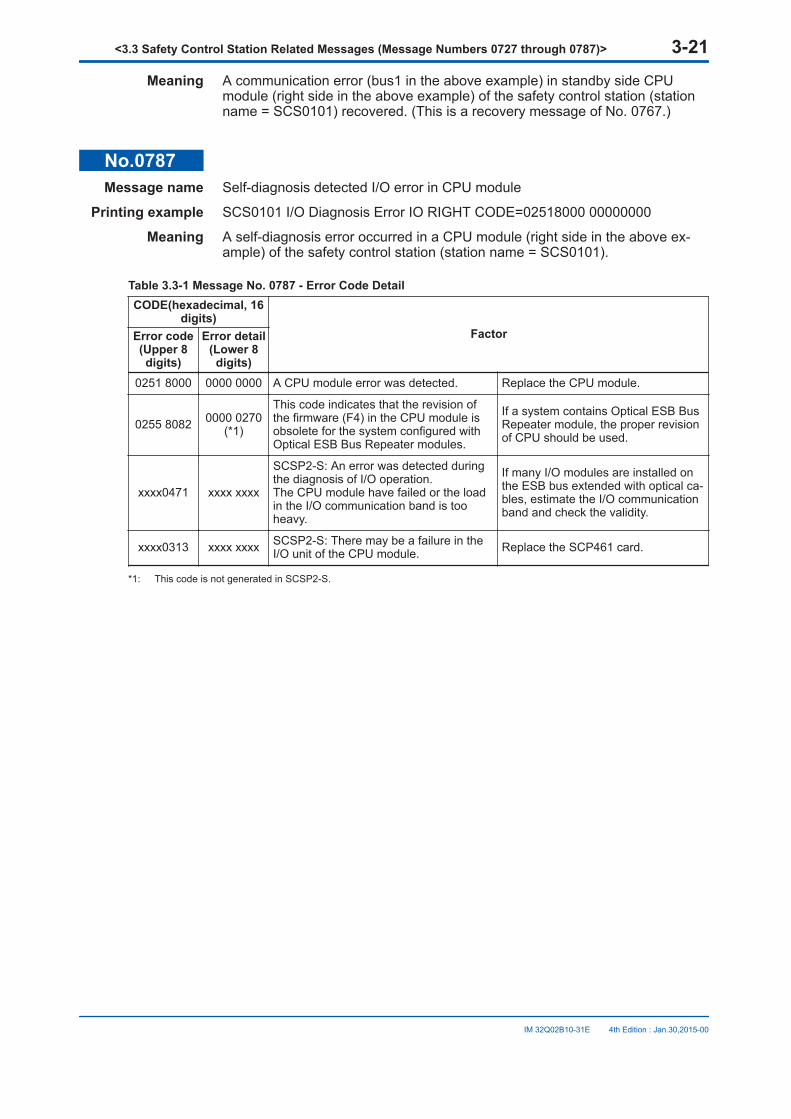
Meaning A communication error (bus1 in the above example) in standby side CPUmodule (right side in the above example) of the safety control station (stationname = SCS0101) recovered. (This is a recovery message of No. 0767.)
No.0787Message name Self-diagnosis detected I/O error in CPU module
Printing example SCS0101 I/O Diagnosis Error IO RIGHT CODE=02518000 00000000
Meaning A self-diagnosis error occurred in a CPU module (right side in the above ex-ample) of the safety control station (station name = SCS0101).
Table 3.3-1 Message No. 0787 - Error Code DetailCODE(hexadecimal, 16
digits)FactorError code
(Upper 8digits)
Error detail(Lower 8digits)
0251 8000 0000 0000 A CPU module error was detected. Replace the CPU module.
0255 8082 0000 0270(*1)
This code indicates that the revision ofthe firmware (F4) in the CPU module isobsolete for the system configured withOptical ESB Bus Repeater modules.
If a system contains Optical ESB BusRepeater module, the proper revisionof CPU should be used.
xxxx0471 xxxx xxxx
SCSP2-S: An error was detected duringthe diagnosis of I/O operation.The CPU module have failed or the loadin the I/O communication band is tooheavy.
If many I/O modules are installed onthe ESB bus extended with optical ca-bles, estimate the I/O communicationband and check the validity.
xxxx0313 xxxx xxxx SCSP2-S: There may be a failure in theI/O unit of the CPU module. Replace the SCP461 card.
*1: This code is not generated in SCSP2-S.
<3.3 Safety Control Station Related Messages (Message Numbers 0727 through 0787)> 3-21
IM 32Q02B10-31E 4th Edition : Jan.30,2015-00

Appendix 1. Alarm ClassThe following table shows the alarm class that is added to each Diagnostic Information Mes-sage.
Table Appendix 1-1 Alarm ClassMessage number Message name Alarm class
0001 Reset start of safety control station 2
0003 Safety control station automatic reset start 2
0005 Power ON initial cold start of safety control station 2
0009 Transfer of control right of safety control station 2
0011 Fail information of safety control station 2
0013 AC power supply failure of safety control station 2
0015 Self-diagnosis error of clock inside CPU module 2
0017 ROM checksum error of CPU module 2
0021 Internal task error of safety control station 2
0023 Mapping block fatal error 2
0025 Function control word error 2
0027 Mapping block record information error 2
0033 Online downloading abnormal end 2
0041 Safety control station fan alarm 2
0042 Recovery from safety control station fan alarm 3
0043 Safety control station temperature alarm 2
0044 Recovery from safety control station temperature alarm 3
0045 Power supply module alarm of safety control station 2
0046 Recovery from power supply module alarm of safety controlstation
3
0047 Battery alarm of CPU module 2
0048 Recovery from battery alarm of CPU module 3
0055 Information of same frame reception in online change down-load communication
2
0057 Information of online change download error 2
0059 Information of recovery from node power failure 1
0063 ESB bus error 1, or 2
0064 Normal recovery of ESB bus 3
0065 Failure of ESB Bus Interface module (SSB401) of node 1, or 2
0066 Normal recovery of ESB Bus Interface module (SSB401) ofnode
3
0067 Failure of power supply module of node 1, or 2
0068 Normal recovery of power supply module of a node 3
0069 Error before database download to I/O module 1, or 2
0081 Failure of I/O module 1, or 2
0082 Normal recovery of I/O module 3
0083 I/O module database error occurred 1, or 2
Continues on the next page
<Appendix 1. Alarm Class> App.1-1
IM 32Q02B10-31E 4th Edition : Jan.30,2015-00
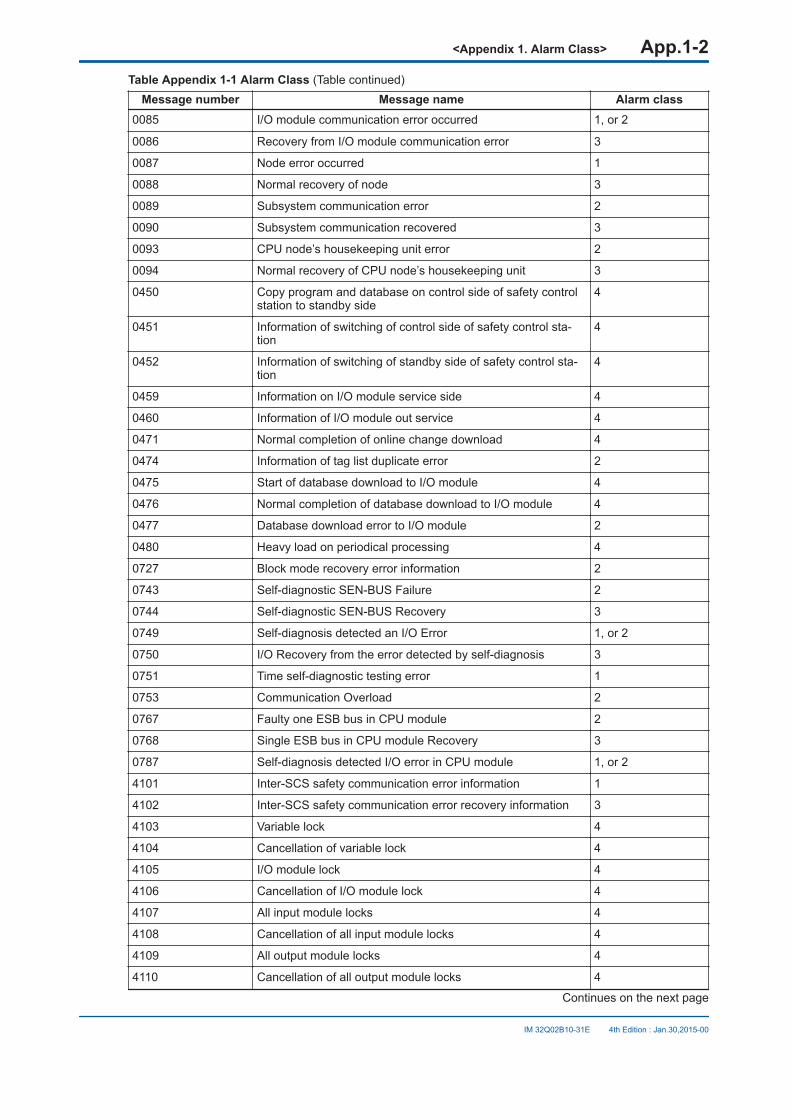
Table Appendix 1-1 Alarm Class (Table continued)Message number Message name Alarm class
0085 I/O module communication error occurred 1, or 2
0086 Recovery from I/O module communication error 3
0087 Node error occurred 1
0088 Normal recovery of node 3
0089 Subsystem communication error 2
0090 Subsystem communication recovered 3
0093 CPU node’s housekeeping unit error 2
0094 Normal recovery of CPU node’s housekeeping unit 3
0450 Copy program and database on control side of safety controlstation to standby side
4
0451 Information of switching of control side of safety control sta-tion
4
0452 Information of switching of standby side of safety control sta-tion
4
0459 Information on I/O module service side 4
0460 Information of I/O module out service 4
0471 Normal completion of online change download 4
0474 Information of tag list duplicate error 2
0475 Start of database download to I/O module 4
0476 Normal completion of database download to I/O module 4
0477 Database download error to I/O module 2
0480 Heavy load on periodical processing 4
0727 Block mode recovery error information 2
0743 Self-diagnostic SEN-BUS Failure 2
0744 Self-diagnostic SEN-BUS Recovery 3
0749 Self-diagnosis detected an I/O Error 1, or 2
0750 I/O Recovery from the error detected by self-diagnosis 3
0751 Time self-diagnostic testing error 1
0753 Communication Overload 2
0767 Faulty one ESB bus in CPU module 2
0768 Single ESB bus in CPU module Recovery 3
0787 Self-diagnosis detected I/O error in CPU module 1, or 2
4101 Inter-SCS safety communication error information 1
4102 Inter-SCS safety communication error recovery information 3
4103 Variable lock 4
4104 Cancellation of variable lock 4
4105 I/O module lock 4
4106 Cancellation of I/O module lock 4
4107 All input module locks 4
4108 Cancellation of all input module locks 4
4109 All output module locks 4
4110 Cancellation of all output module locks 4
Continues on the next page
<Appendix 1. Alarm Class> App.1-2
IM 32Q02B10-31E 4th Edition : Jan.30,2015-00
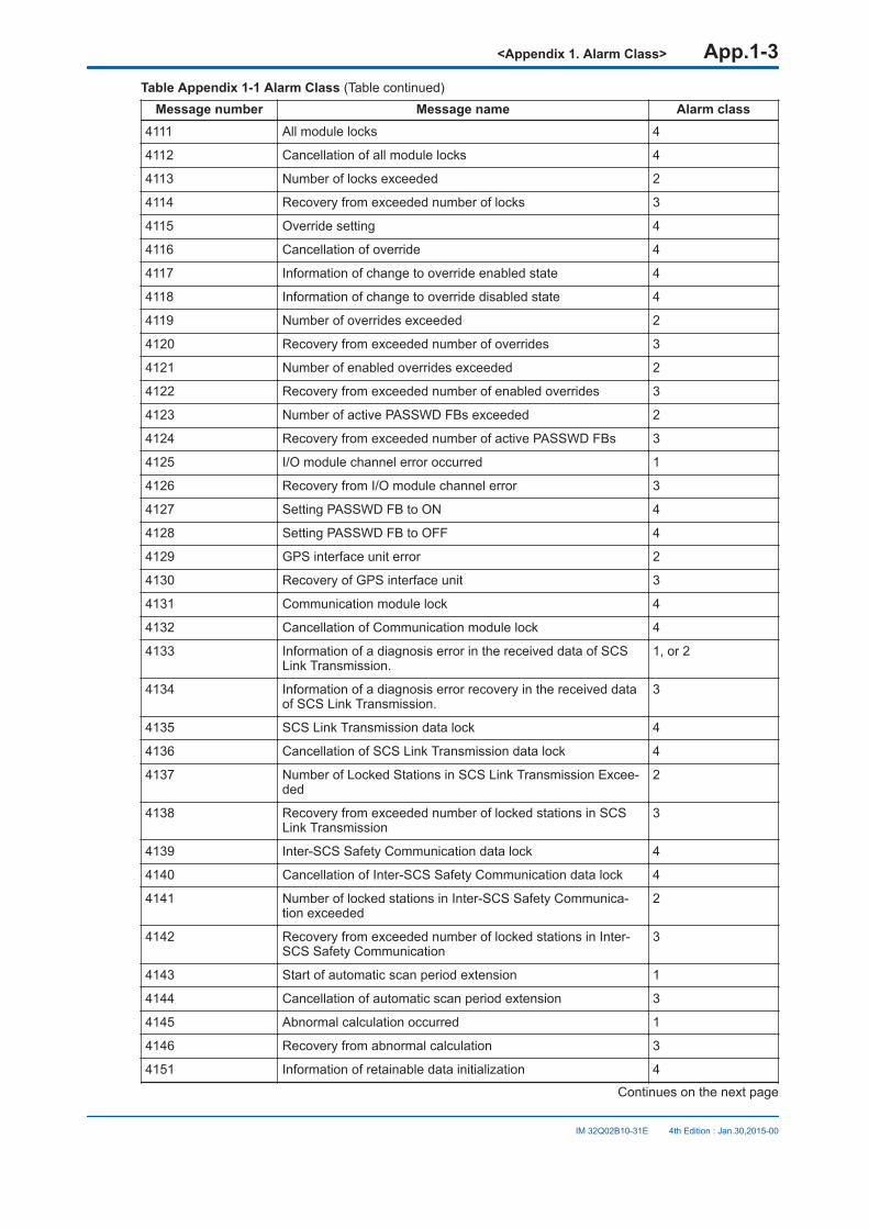
Table Appendix 1-1 Alarm Class (Table continued)Message number Message name Alarm class
4111 All module locks 4
4112 Cancellation of all module locks 4
4113 Number of locks exceeded 2
4114 Recovery from exceeded number of locks 3
4115 Override setting 4
4116 Cancellation of override 4
4117 Information of change to override enabled state 4
4118 Information of change to override disabled state 4
4119 Number of overrides exceeded 2
4120 Recovery from exceeded number of overrides 3
4121 Number of enabled overrides exceeded 2
4122 Recovery from exceeded number of enabled overrides 3
4123 Number of active PASSWD FBs exceeded 2
4124 Recovery from exceeded number of active PASSWD FBs 3
4125 I/O module channel error occurred 1
4126 Recovery from I/O module channel error 3
4127 Setting PASSWD FB to ON 4
4128 Setting PASSWD FB to OFF 4
4129 GPS interface unit error 2
4130 Recovery of GPS interface unit 3
4131 Communication module lock 4
4132 Cancellation of Communication module lock 4
4133 Information of a diagnosis error in the received data of SCSLink Transmission.
1, or 2
4134 Information of a diagnosis error recovery in the received dataof SCS Link Transmission.
3
4135 SCS Link Transmission data lock 4
4136 Cancellation of SCS Link Transmission data lock 4
4137 Number of Locked Stations in SCS Link Transmission Excee-ded
2
4138 Recovery from exceeded number of locked stations in SCSLink Transmission
3
4139 Inter-SCS Safety Communication data lock 4
4140 Cancellation of Inter-SCS Safety Communication data lock 4
4141 Number of locked stations in Inter-SCS Safety Communica-tion exceeded
2
4142 Recovery from exceeded number of locked stations in Inter-SCS Safety Communication
3
4143 Start of automatic scan period extension 1
4144 Cancellation of automatic scan period extension 3
4145 Abnormal calculation occurred 1
4146 Recovery from abnormal calculation 3
4151 Information of retainable data initialization 4
Continues on the next page
<Appendix 1. Alarm Class> App.1-3
IM 32Q02B10-31E 4th Edition : Jan.30,2015-00

Table Appendix 1-1 Alarm Class (Table continued)Message number Message name Alarm class
4152 Online change of scan period 4
4153 Information of Inter-SCS Safety Communication data locktime-up
2
4154 Information of forced cancellation of Inter-SCS Safety Com-munication data locks
4
4155 Information of SCS Link Transmission status change. 4
4156 Information of SCS Link Transmission definition change 4
4157 Information of SCS Link Transmission wiring change 4
4158 Information of SCS Link Transmission lock time-up 2
4159 Information of forced cancellation of SCS Link Transmissionlocks
4
4160 Invalid password for Manual Operation FB 4
4161 Information of Output IOM Shutdown 4
4162 Information of communication I/O definition change 4
4163 Information of communication I/O wiring change 4
4164 Information of disabling security level change 4
4165 Information of enabling security level change 4
4166 Information of communication module lock time-up 2
4167 Information of forced cancellation of communication modulelocks
4
4168 Information of tag name change by online change download 4
4169 NVRAM diagnosis error 2
4170 Flash memory diagnosis error 2
4172 Information of resource change by online change download 4
4173 Completion of writing to flash memory 4
4174 Failed to write to flash memory 2
4175 Failed to update external communication data 2
4177 Information of SCS security level change 4
4178 Information of security level time-up 2
4179 Information of communication I/O module output enabled op-eration
4
4180 Information of password change 4
4181 Information of output enabled operation 4
4182 Information of output module start operation 4
4183 Request to upload SOE to SENG 4
4184 Notification on saving SOE trip signal file in SCS 4
4185 Information of variable value change 4
4186 Information of lock time-up 2
4187 Information of forced cancellation of locks 4
4188 Start of online change download 4
4189 Completion of online change download 4
4190 Online change download error 2
Continues on the next page
<Appendix 1. Alarm Class> App.1-4
IM 32Q02B10-31E 4th Edition : Jan.30,2015-00
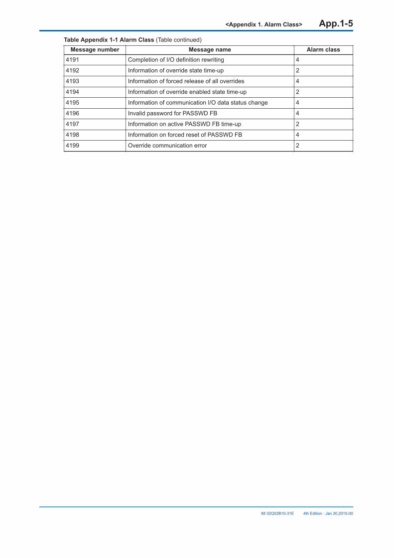
Table Appendix 1-1 Alarm Class (Table continued)Message number Message name Alarm class
4191 Completion of I/O definition rewriting 4
4192 Information of override state time-up 2
4193 Information of forced release of all overrides 4
4194 Information of override enabled state time-up 2
4195 Information of communication I/O data status change 4
4196 Invalid password for PASSWD FB 4
4197 Information on active PASSWD FB time-up 2
4198 Information on forced reset of PASSWD FB 4
4199 Override communication error 2
<Appendix 1. Alarm Class> App.1-5
IM 32Q02B10-31E 4th Edition : Jan.30,2015-00

Revision InformationTitle : Messages
Manual No. : IM 32Q02B10-31E
Jan. 2015/4th Edition/R3.02.20 or later*
*: Denotes the release number of the Software Product corresponding to the contents of this Man-ual. The revised contents are valid until the next edition is issued.
Introduction ProSafe-RS document map has been removed,descriptions of “Safety, Protection, and Modifica-tion of the Product” have been modified.
No.0081, No.0477 Descriptions of messages changed.
Oct. 2013/3rd Edition/R3.02.10 or later
Introduction Description of station types has been changed.
No.4151 New message added.
Appendix 1 No.4151 added.
Dec. 2012/2nd Edition/R3.02 or later
1.1, 1.2 Descriptions changed.
No.4145, No.4146, No.0081, No.0477, No.0749 Descriptions of messages changed.
Appendix 1 Newly added.
Aug. 2011/1st Edition/R3.01 or laterNewly published.
n
For Questions and More InformationOnline Query: A query form is available on the following URL for online query.http://www.yokogawa.com/iss
n Written by Yokogawa Electric Corporationn Published by Yokogawa Electric Corporation
2-9-32 Nakacho, Musashino-shi, Tokyo 180-8750, JAPAN
Rev-1
IM 32Q02B10-31E 4th Edition : Jan.30,2015-00


![User’s Manual - Yokogawa Electriccdn2.us.yokogawa.com/IM01C22T01-01EN_008.pdf · Contents of this User’s Manual for HART Protocol ... Call "Device setup" and press [→]. 3) Call](https://img.pdfslide.us/doc/110x75/5b0e2c577f8b9af65e8eb0d5/users-manual-yokogawa-of-this-users-manual-for-hart-protocol-call-device.jpg)