Embed Size (px)
Citation preview

Yokogawa Electric Corporation SBDB-110015
1/36
PST Scheduler Engineering Guide with
Metso positioner
Yokogawa Electric Corporation SBDB-110015
2/36
Copyright and Trademark Notices
■■■■ Trademark Acknowledgments All Right Reserved, Copyright 2011 © Yokogawa Electric Corporation
For Chapter 8 courtesy of Metso, Copyright 2011 © Metso.
■■■■ Trademark Acknowledgments ・ PRM is a registered trademark of Yokogawa Electric Corporation in the United States and
Japan.
・ ProSafe and Vnet/IP are registered trademarks of YOKOGAWA.
・ Microsoft, Windows are either registered trademarks or trademarks of Microsoft Corporation in
the United States and/or other countries.
・ Ethernet is a registered trademark of XEROX Corporation.
・ HART is a registered trademark of the HART Communication Foundation.
・ All other company and product names mentioned in this manual are trademarks or registered
trademarks of their respective companies.
・ We do not use TM or ® mark to indicate those trademarks or registered trademarks in this
manual.

Yokogawa Electric Corporation SBDB-110015
3/36
Contents
1 Introduction .............................................................................................................................................. 4
2 PST Device................................................................................................................................................ 5
3 System configuration................................................................................................................................ 6
4 PST Scheduler workflow.......................................................................................................................... 7
5 Detailed PST Scheduler setup................................................................................................................. 8
5.1 Connection between device and controller (SCS) ........................................................................... 8
5.2 Registration to PRM of device.......................................................................................................... 8
5.3 Exporting the device list................................................................................................................. 10
5.4 Configuring the PST Scheduler Client connection........................................................................11
5.5 Starting the PST Scheduler Client.................................................................................................11
5.6 Importing device information......................................................................................................... 12
5.7 Managing PST groups .................................................................................................................... 14
5.8 Arranging devices into groups ....................................................................................................... 14
5.9 Scheduling a PST............................................................................................................................ 15
5.10 Check a PST function ..................................................................................................................... 16
5.11 Confirm the status of the PST function in PRM........................................................................... 17
6 The PST setting...................................................................................................................................... 18
7 The example of PST schedule................................................................................................................ 19
7.1 Maximum duration......................................................................................................................... 19
7.2 PST Mode ........................................................................................................................................ 20
7.3 PST Execution Mode....................................................................................................................... 21
8 The connection for every device............................................................................................................. 22
8.1 Metso VG800................................................................................................................................... 22
8.1.1 Feature......................................................................................................................................... 22
8.1.2 System configuration .................................................................................................................. 23
8.1.3 Equipments list ........................................................................................................................... 24
8.1.4 DTM............................................................................................................................................. 25
8.1.5 Wiring .......................................................................................................................................... 26
8.1.6 Application................................................................................................................................... 27
8.1.7 PST related parameter ............................................................................................................... 27
8.1.8 Valve operation in PST ............................................................................................................... 28
8.2 Metso VG9000H.............................................................................................................................. 28
8.2.1 Feature......................................................................................................................................... 28
8.2.2 System configuration .................................................................................................................. 30
8.2.3 Equipments list ........................................................................................................................... 32
8.2.4 DTM............................................................................................................................................. 32
8.2.5 Wiring .......................................................................................................................................... 33
8.2.6 Application................................................................................................................................... 35
8.2.7 PST related parameter ............................................................................................................... 35
8.2.8 Valve operation in PST ............................................................................................................... 36
Yokogawa Electric Corporation SBDB-110015
4/36
1 Introduction
This document is an engineering guide of PST Scheduler (the R3.04.00 or later edition of PRM) with
Metso positioner. The purpose of this document is for an engineer to understand how to use PST
Scheduler and to build a demo system. Therefore, it is the minimum composition needed in order to
operate PST. In a real job, the system configuration and engineering according to plant operation are
required.
Chapter 2 – 7: Engineering guide of PST Scheduler.
Chapter 8: Settings for Metso positioner.
Yokogawa Electric Corporation SBDB-110015
5/36
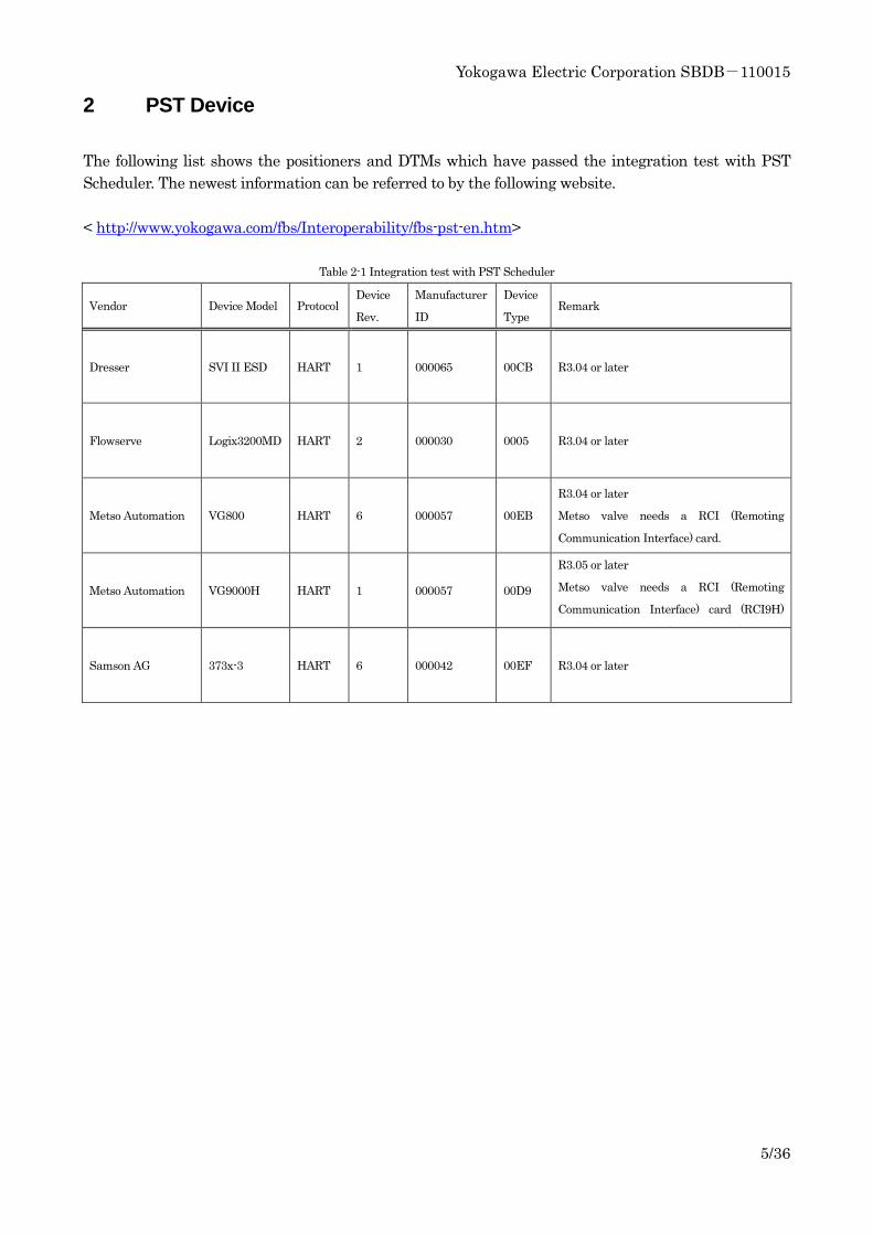
2 PST Device
The following list shows the positioners and DTMs which have passed the integration test with PST
Scheduler. The newest information can be referred to by the following website.
< http://www.yokogawa.com/fbs/Interoperability/fbs-pst-en.htm>
Table 2-1 Integration test with PST Scheduler
Vendor Device Model Protocol Device
Rev.
Manufacturer
ID
Device
Type Remark
Dresser SVI II ESD HART 1 000065 00CB R3.04 or later
Flowserve Logix3200MD HART 2 000030 0005 R3.04 or later
Metso Automation VG800 HART 6 000057 00EB
R3.04 or later
Metso valve needs a RCI (Remoting
Communication Interface) card.
Metso Automation VG9000H HART 1 000057 00D9
R3.05 or later
Metso valve needs a RCI (Remoting
Communication Interface) card (RCI9H)
when connected to safety system DO.
Samson AG 373x-3 HART 6 000042 00EF R3.04 or later
Yokogawa Electric Corporation SBDB-110015
6/36
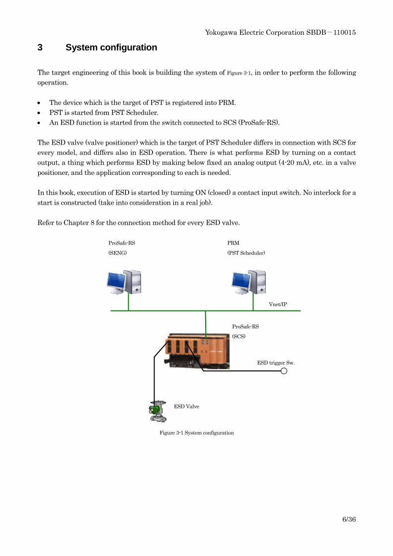
3 System configuration
The target engineering of this book is building the system of Figure 3-1, in order to perform the following
operation.
• The device which is the target of PST is registered into PRM.
• PST is started from PST Scheduler.
• An ESD function is started from the switch connected to SCS (ProSafe-RS).
The ESD valve (valve positioner) which is the target of PST Scheduler differs in connection with SCS for
every model, and differs also in ESD operation. There is what performs ESD by turning on a contact
output, a thing which performs ESD by making below fixed an analog output (4-20 mA), etc. in a valve
positioner, and the application corresponding to each is needed.
In this book, execution of ESD is started by turning ON (closed) a contact input switch. No interlock for a
start is constructed (take into consideration in a real job).
Refer to Chapter 8 for the connection method for every ESD valve.
Figure 3-1 System configuration
ProSafe-RS
(SENG)
PRM
(PST Scheduler)
ESD trigger Sw.
ProSafe-RS
(SCS)
Vnet/IP
ESD Valve
Yokogawa Electric Corporation SBDB-110015
7/36
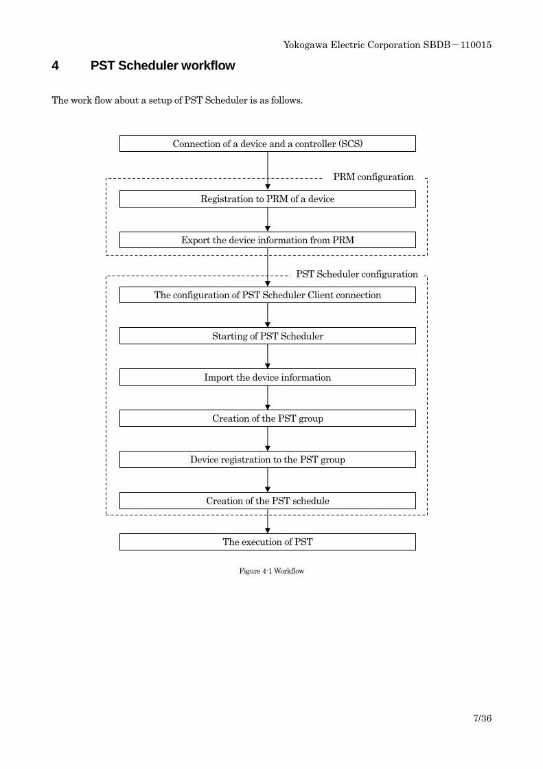
4 PST Scheduler workflow
The work flow about a setup of PST Scheduler is as follows.
Figure 4-1 Workflow
Registration to PRM of a device
Import the device information
Creation of the PST group
Device registration to the PST group
Creation of the PST schedule
The execution of PST
Starting of PST Scheduler
The configuration of PST Scheduler Client connection
Export the device information from PRM
Connection of a device and a controller (SCS)
PRM configuration
PST Scheduler configuration
Yokogawa Electric Corporation SBDB-110015
8/36
5 Detailed PST Scheduler setup
The details of each work in a setup of PST Scheduler are described below.
5.1 Connection between device and controller (SCS)
The device (valve positioner) which performs PST is connected to a controller (SCS). Refer to Chapter 8
for the connection method.
5.2 Registration to PRM of device
The device needs to be registered into PRM in order to operate a device by PST Scheduler.
1) Set up Device Path
About IO module which connected the device, Device Path is set up with the setup tool of PRM.
2) DD file copy
DD file of a device is copied to the folder of PRM. DD file comes to hand from a vendor. The copy
place of a DD file is as follows.
(PRM installation drive)¥PRM¥DD¥HART¥(Manufacturer ID)¥(Device Type)
* Refer to Table 2-1 for Manufacturer ID and Device Type.
3) DTM installation
DTM of an object device is installed. DTM comes to hand from a vendor.
4) Plug & Play Execution
Plug & Play is performed by PRM and a device is registered.
-Trouble Shoot
A device cannot be recognized
->The connection mistake of a device
->The HART module of a valve is not operating since the output to a valve is 0% (less than
4mA).
->0.1% or more (100% recommendation) of the output to a valve is used.
->The address is set as the device.
->The address of a device is changed into 0.
->The range of the polling address of a Device Path setup is extended.
Yokogawa Electric Corporation SBDB-110015
9/36
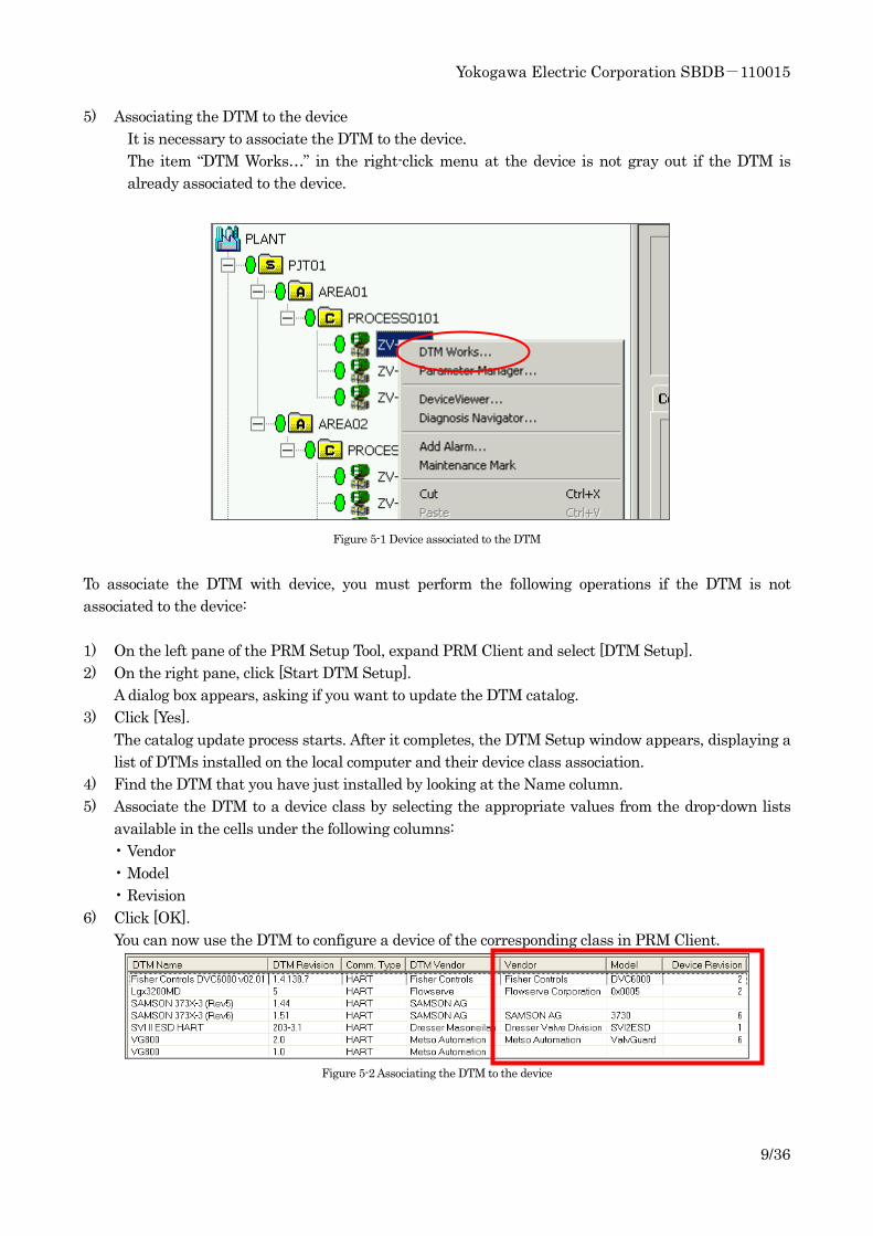
5) Associating the DTM to the device
It is necessary to associate the DTM to the device.
The item “DTM Works…” in the right-click menu at the device is not gray out if the DTM is
already associated to the device.
Figure 5-1 Device associated to the DTM
To associate the DTM with device, you must perform the following operations if the DTM is not
associated to the device:
1) On the left pane of the PRM Setup Tool, expand PRM Client and select [DTM Setup].
2) On the right pane, click [Start DTM Setup].
A dialog box appears, asking if you want to update the DTM catalog.
3) Click [Yes].
The catalog update process starts. After it completes, the DTM Setup window appears, displaying a
list of DTMs installed on the local computer and their device class association.
4) Find the DTM that you have just installed by looking at the Name column.
5) Associate the DTM to a device class by selecting the appropriate values from the drop-down lists
available in the cells under the following columns:
• Vendor
• Model
• Revision
6) Click [OK].
You can now use the DTM to configure a device of the corresponding class in PRM Client.
Figure 5-2 Associating the DTM to the device
Yokogawa Electric Corporation SBDB-110015
10/36
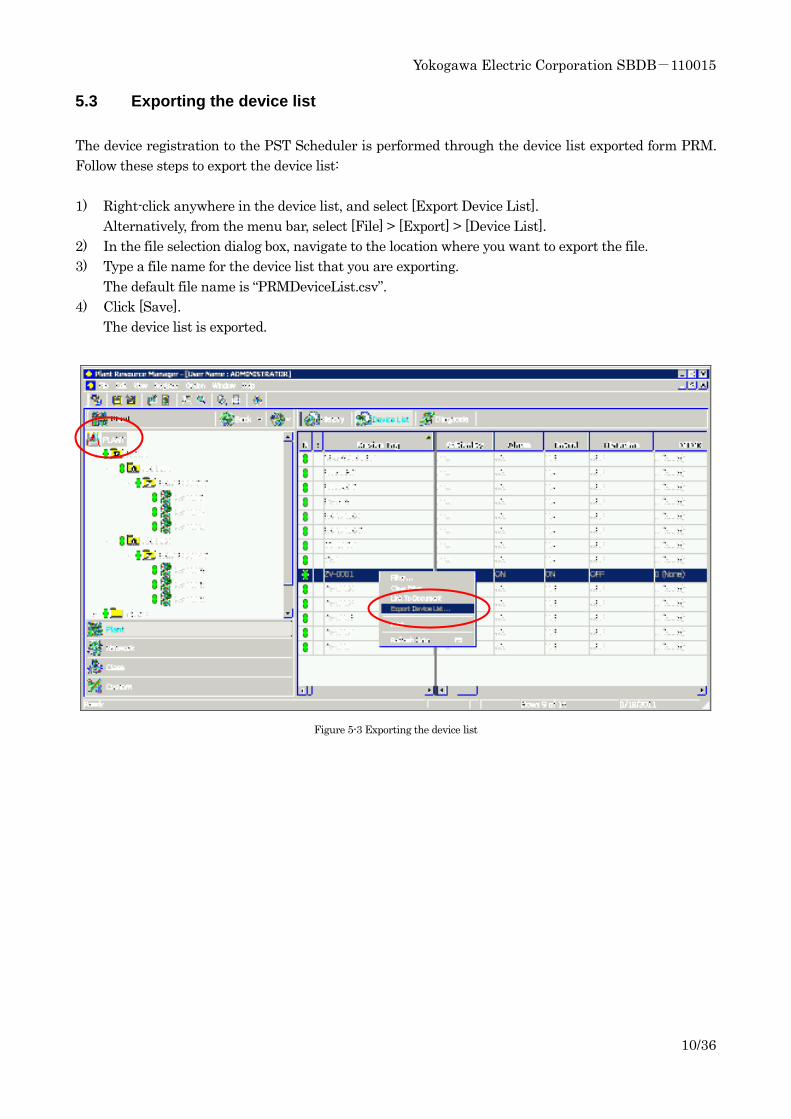
5.3 Exporting the device list
The device registration to the PST Scheduler is performed through the device list exported form PRM.
Follow these steps to export the device list:
1) Right-click anywhere in the device list, and select [Export Device List].
Alternatively, from the menu bar, select [File] > [Export] > [Device List].
2) In the file selection dialog box, navigate to the location where you want to export the file.
3) Type a file name for the device list that you are exporting.
The default file name is “PRMDeviceList.csv”.
4) Click [Save].
The device list is exported.
Figure 5-3 Exporting the device list
Yokogawa Electric Corporation SBDB-110015
11/36
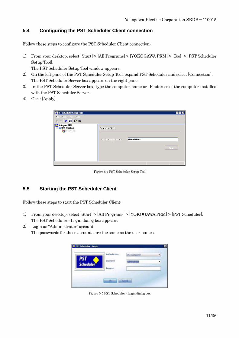
5.4 Configuring the PST Scheduler Client connection
Follow these steps to configure the PST Scheduler Client connection:
1) From your desktop, select [Start] > [All Programs] > [YOKOGAWA PRM] > [Tool] > [PST Scheduler
Setup Tool].
The PST Scheduler Setup Tool window appears.
2) On the left pane of the PST Scheduler Setup Tool, expand PST Scheduler and select [Connection].
The PST Scheduler Server box appears on the right pane.
3) In the PST Scheduler Server box, type the computer name or IP address of the computer installed
with the PST Scheduler Server.
4) Click [Apply].
Figure 5-4 PST Scheduler Setup Tool
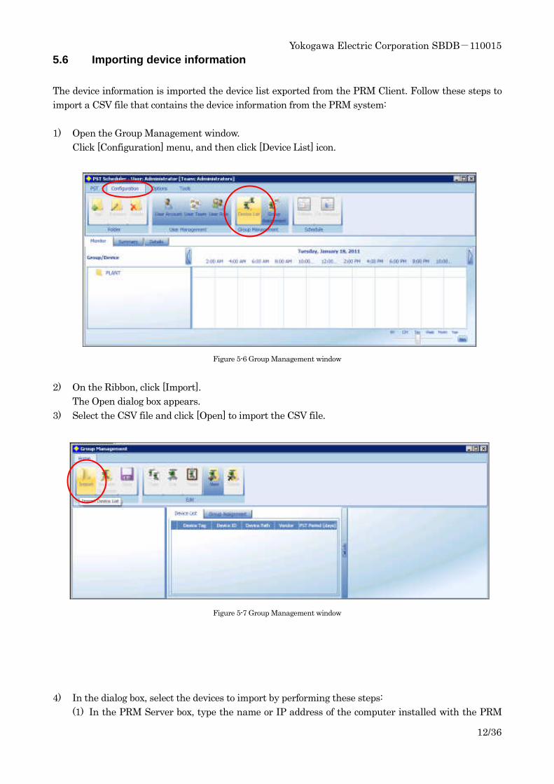
5.5 Starting the PST Scheduler Client
Follow these steps to start the PST Scheduler Client:
1) From your desktop, select [Start] > [All Programs] > [YOKOGAWA PRM] > [PST Scheduler].
The PST Scheduler - Login dialog box appears.
2) Login as “Administrator” account.
The passwords for these accounts are the same as the user names.
Figure 5-5 PST Scheduler - Login dialog box
Yokogawa Electric Corporation SBDB-110015
12/36
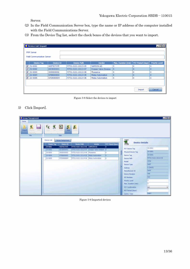
5.6 Importing device information
The device information is imported the device list exported from the PRM Client. Follow these steps to
import a CSV file that contains the device information from the PRM system:
1) Open the Group Management window.
Click [Configuration] menu, and then click [Device List] icon.
Figure 5-6 Group Management window
2) On the Ribbon, click [Import].
The Open dialog box appears.
3) Select the CSV file and click [Open] to import the CSV file.
Figure 5-7 Group Management window
4) In the dialog box, select the devices to import by performing these steps:
(1) In the PRM Server box, type the name or IP address of the computer installed with the PRM
Yokogawa Electric Corporation SBDB-110015
13/36
Server.
(2) In the Field Communication Server box, type the name or IP address of the computer installed
with the Field Communications Server.
(3) From the Device Tag list, select the check boxes of the devices that you want to import.
Figure 5-8 Select the devices to import
5) Click [Import].
Figure 5-9 Imported devices
Yokogawa Electric Corporation SBDB-110015
14/36
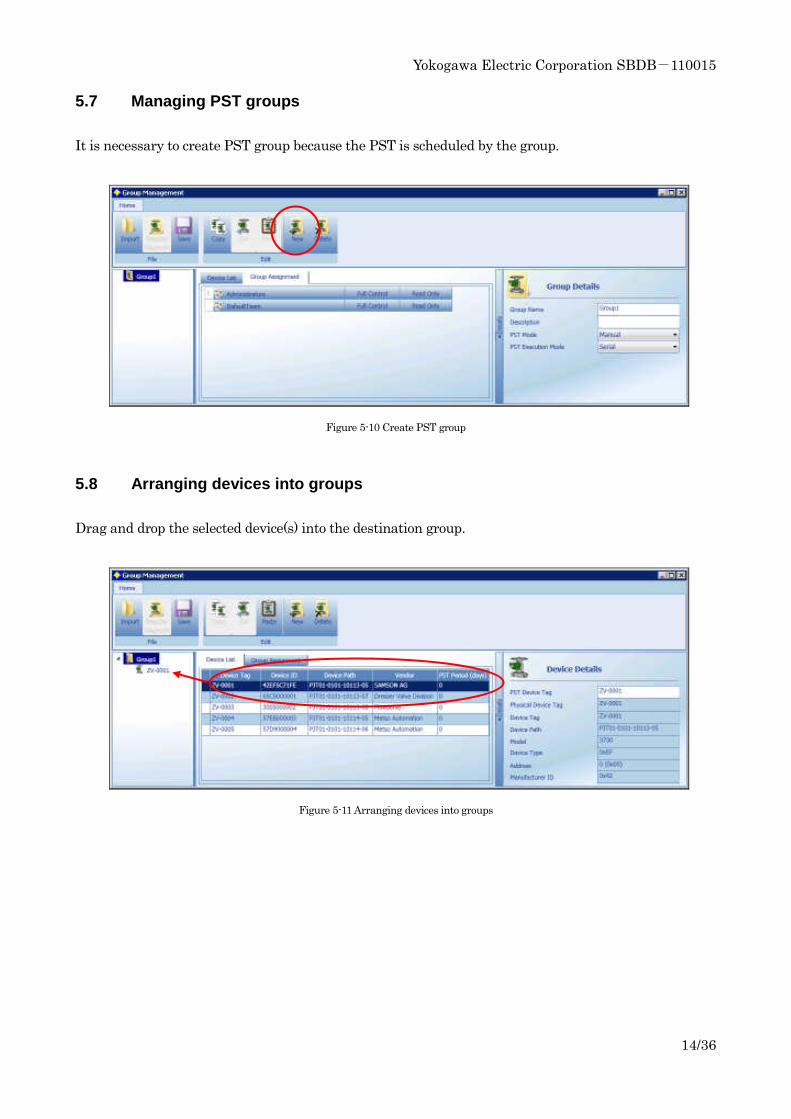
5.7 Managing PST groups
It is necessary to create PST group because the PST is scheduled by the group.
Figure 5-10 Create PST group
5.8 Arranging devices into groups
Drag and drop the selected device(s) into the destination group.
Figure 5-11 Arranging devices into groups
Yokogawa Electric Corporation SBDB-110015
15/36
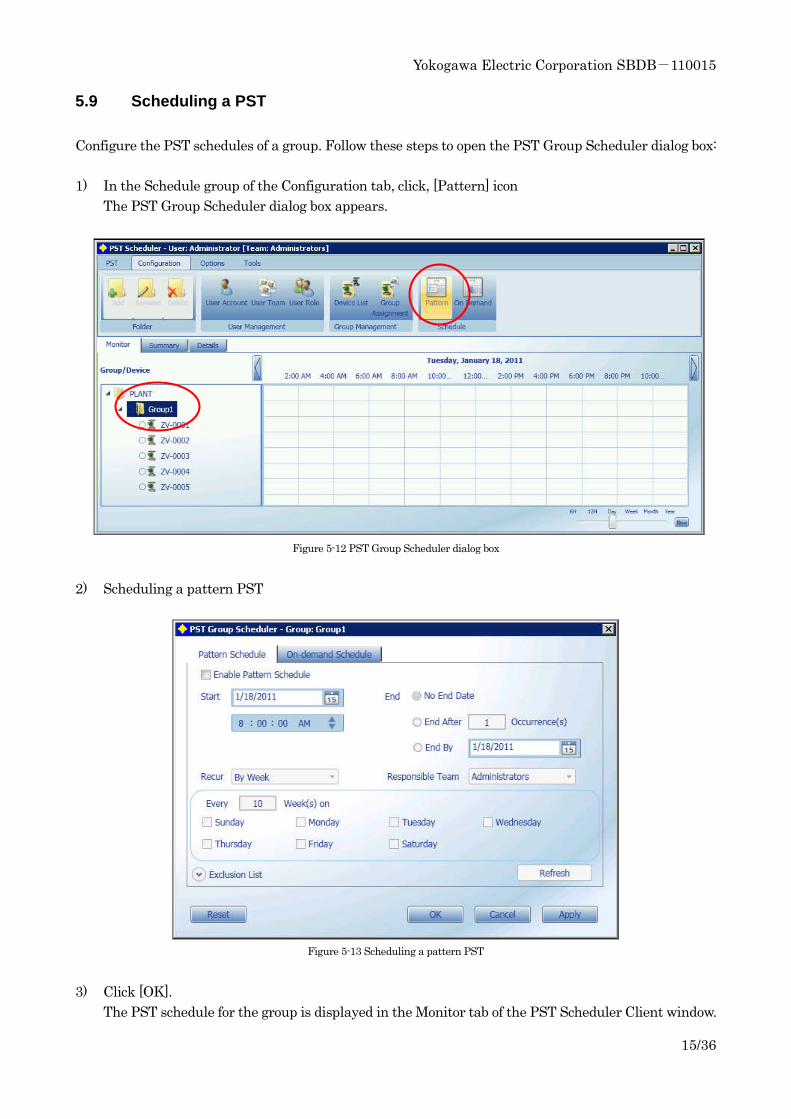
5.9 Scheduling a PST
Configure the PST schedules of a group. Follow these steps to open the PST Group Scheduler dialog box:
1) In the Schedule group of the Configuration tab, click, [Pattern] icon
The PST Group Scheduler dialog box appears.
Figure 5-12 PST Group Scheduler dialog box
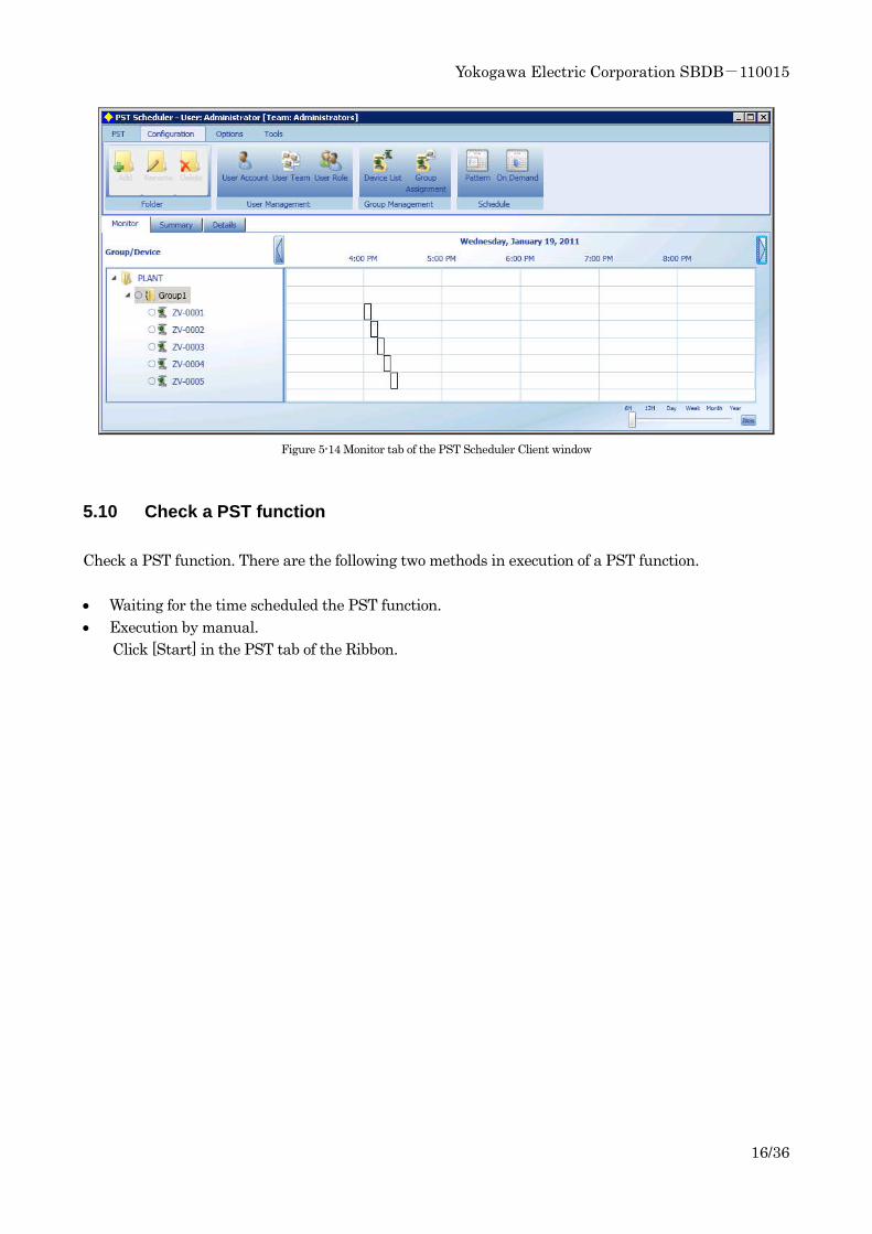
2) Scheduling a pattern PST
Figure 5-13 Scheduling a pattern PST
3) Click [OK].
The PST schedule for the group is displayed in the Monitor tab of the PST Scheduler Client window.
Yokogawa Electric Corporation SBDB-110015
16/36
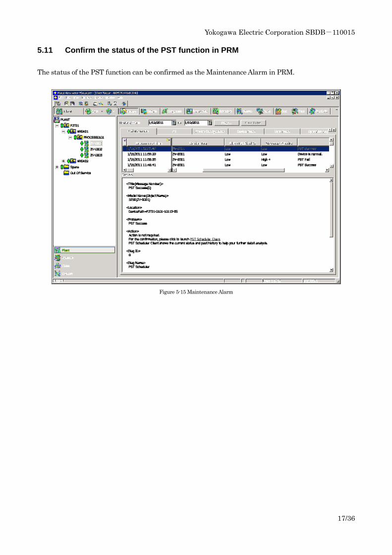
Figure 5-14 Monitor tab of the PST Scheduler Client window
5.10 Check a PST function
Check a PST function. There are the following two methods in execution of a PST function.
• Waiting for the time scheduled the PST function.
• Execution by manual.
Click [Start] in the PST tab of the Ribbon.
Yokogawa Electric Corporation SBDB-110015
17/36
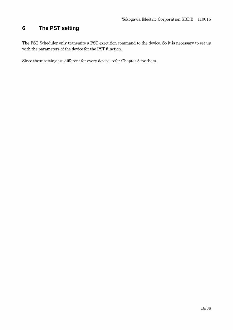
5.11 Confirm the status of the PST function in PRM
The status of the PST function can be confirmed as the Maintenance Alarm in PRM.
Figure 5-15 Maintenance Alarm
Yokogawa Electric Corporation SBDB-110015
18/36
6 The PST setting
The PST Scheduler only transmits a PST execution command to the device. So it is necessary to set up
with the parameters of the device for the PST function.
Since these setting are different for every device, refer Chapter 8 for them.
Yokogawa Electric Corporation SBDB-110015
19/36
7 The example of PST schedule
The sample setting for the demonstration is given.
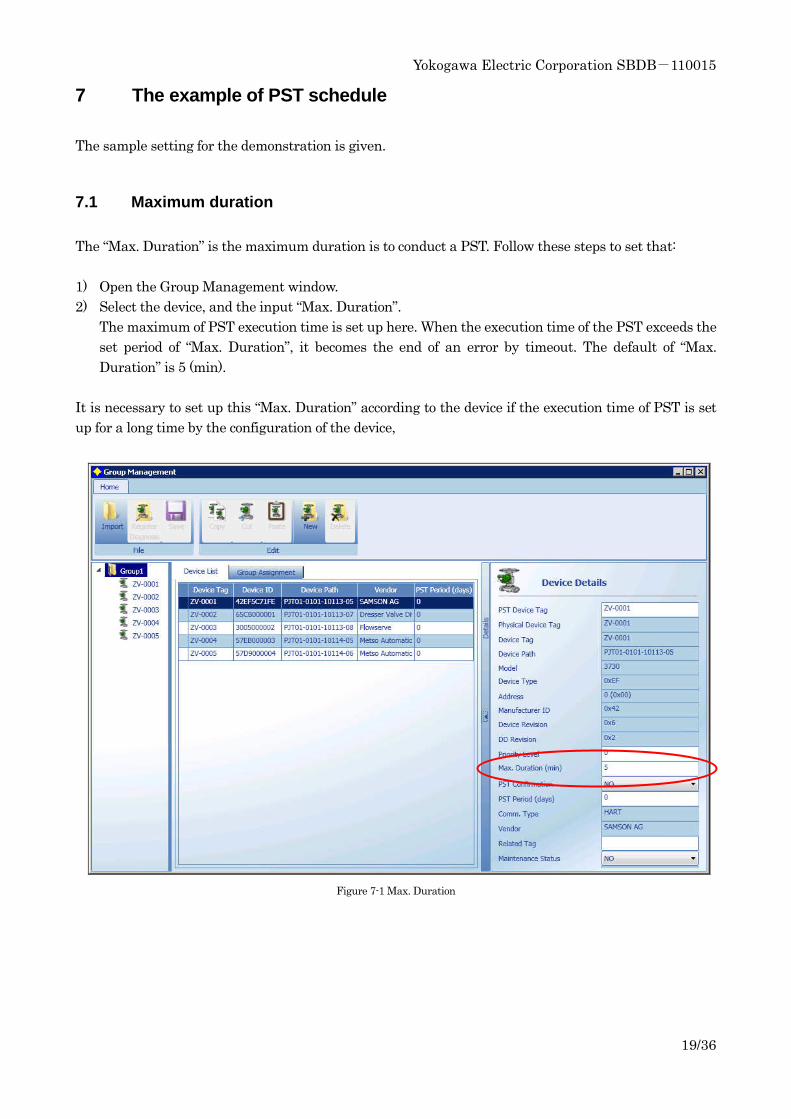
7.1 Maximum duration
The “Max. Duration” is the maximum duration is to conduct a PST. Follow these steps to set that:
1) Open the Group Management window.
2) Select the device, and the input “Max. Duration”.
The maximum of PST execution time is set up here. When the execution time of the PST exceeds the
set period of “Max. Duration”, it becomes the end of an error by timeout. The default of “Max.
Duration” is 5 (min).
It is necessary to set up this “Max. Duration” according to the device if the execution time of PST is set
up for a long time by the configuration of the device,
Figure 7-1 Max. Duration
Yokogawa Electric Corporation SBDB-110015
20/36
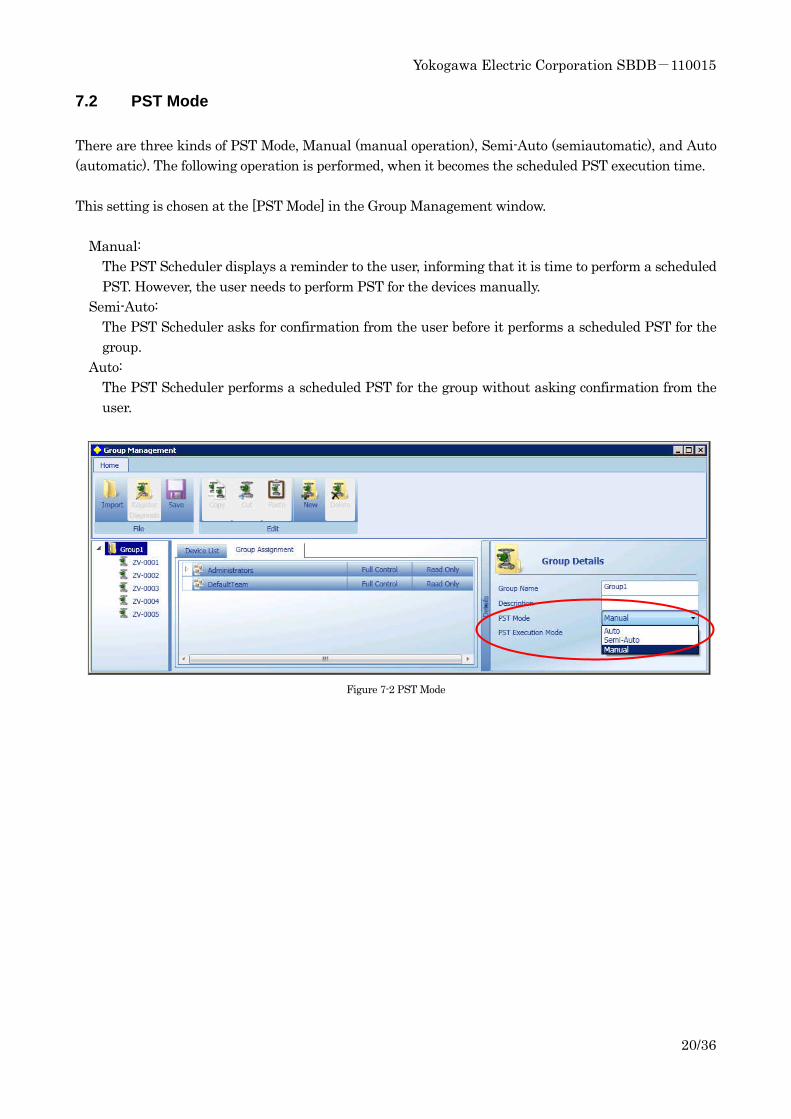
7.2 PST Mode
There are three kinds of PST Mode, Manual (manual operation), Semi-Auto (semiautomatic), and Auto
(automatic). The following operation is performed, when it becomes the scheduled PST execution time.
This setting is chosen at the [PST Mode] in the Group Management window.
Manual:
The PST Scheduler displays a reminder to the user, informing that it is time to perform a scheduled
PST. However, the user needs to perform PST for the devices manually.
Semi-Auto:
The PST Scheduler asks for confirmation from the user before it performs a scheduled PST for the
group.
Auto:
The PST Scheduler performs a scheduled PST for the group without asking confirmation from the
user.
Figure 7-2 PST Mode
Yokogawa Electric Corporation SBDB-110015
21/36
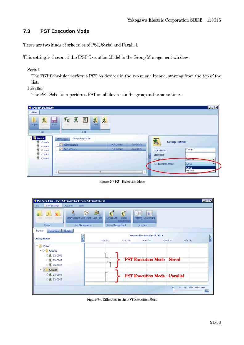
7.3 PST Execution Mode
There are two kinds of schedules of PST, Serial and Parallel.
This setting is chosen at the [PST Execution Mode] in the Group Management window.
Serial:
The PST Scheduler performs PST on devices in the group one by one, starting from the top of the
list.
Parallel:
The PST Scheduler performs PST on all devices in the group at the same time.
Figure 7-3 PST Execution Mode
Figure 7-4 Difference in the PST Execution Mode
PST Execution MPST Execution MPST Execution MPST Execution Moooodededede::::SerialSerialSerialSerial
PST Execution MPST Execution MPST Execution MPST Execution Moooodededede::::ParallelParallelParallelParallel
Yokogawa Electric Corporation SBDB-110015
22/36
8 The connection for every device
8.1 Metso VG800
8.1.1 Feature
There are the following features in this device.
ESD:
The ESD function will operate, if the power supply (24VDC) is down. So it cannot communicate with
HART protocol during the ESD function working.
SIL:
This device is certified by SIL3.
FST:
It can perform FST (Full Stroke Test) using PST Scheduler if the parameter for working range of
PST is set. (Test Stroke Size: 100%)
Connection between ProSafe-RS and PRM:
It is necessary to use the RCI (Remote Communication Interface) for connecting with this device.
HART communication is made by AO or AI module. This module is used for HART communication
and it also provides binary status relays for alarm and testing.
Notes:
• The settings of “Off pulse test“ and “detect disconnection test“ must be disabled. This setting does
not affect the SIL level for ESD application.
• Please note the result indication on PST scheduler may not correct on the first PST after 24V ON.
Yokogawa Electric Corporation SBDB-110015
23/36
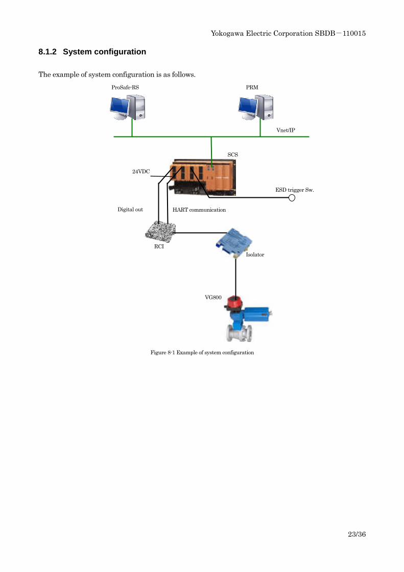
8.1.2 System configuration
The example of system configuration is as follows.
Figure 8-1 Example of system configuration
ProSafe-RS PRM
ESD trigger Sw.
Digital out HART communication
RCI
Isolator
VG800
SCS
Vnet/IP
24VDC
Yokogawa Electric Corporation SBDB-110015
24/36
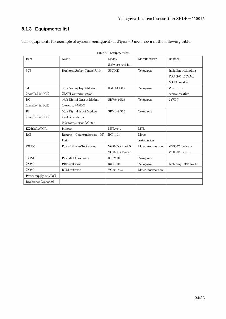
8.1.3 Equipments list
The equipments for example of systems configuration (Figure 8-1) are shown in the following table.
Table 8-1 Equipment list
Item Name Model/
Software revision
Manufacturer Remark
SCS
Duplexed Safety Control Unit SSC50D Yokogawa Including redundant
PSU (100-120VAC)
& CPU module
AI
(installed in SCS)
16ch Analog Input Module
(HART communication)
SAI143-H33 Yokogawa With Hart
communication
DO
(installed in SCS)
16ch Digital Output Module
(power to VG800)
SDV541-S23 Yokogawa 24VDC
DI
(installed in SCS)
16ch Digital Input Module
(real-time status
information from VG800)
SDV144-S13 Yokogawa
EX-ISOLATOR Isolator MTL5042 MTL
RCI Remote Communication I/F
Unit
RCI 1.01 Metso
Automation
VG800 Partial Stroke Test device VG800X / Rev2.0
VG800B / Rev 2.0
Metso Automation VG800X for Ex ia
VG800B for Ex d
(SENG) ProSafe-RS software R1.02.00 Yokogawa
(PRM) PRM software R3.04.00 Yokogawa Including DTM works
(PRM) DTM software VG800 / 2.0 Metso Automation
Power supply (24VDC)
Resistance (250 ohm)
Yokogawa Electric Corporation SBDB-110015
25/36
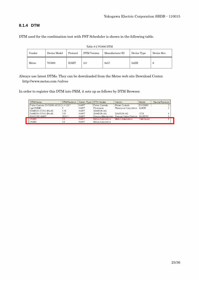
8.1.4 DTM
DTM used for the combination test with PST Scheduler is shown in the following table.
Table 8-2 VG800 DTM
Vendor Device Model Protocol DTM Version Manufacturer ID Device Type Device Rev.
Metso VG800 HART 2.0 0x57 0xEB 6
Always use latest DTMs. They can be downloaded from the Metso web site Download Center.
http://www.metso.com /valves
In order to register this DTM into PRM, it sets up as follows by DTM Browser.
Yokogawa Electric Corporation SBDB-110015
26/36
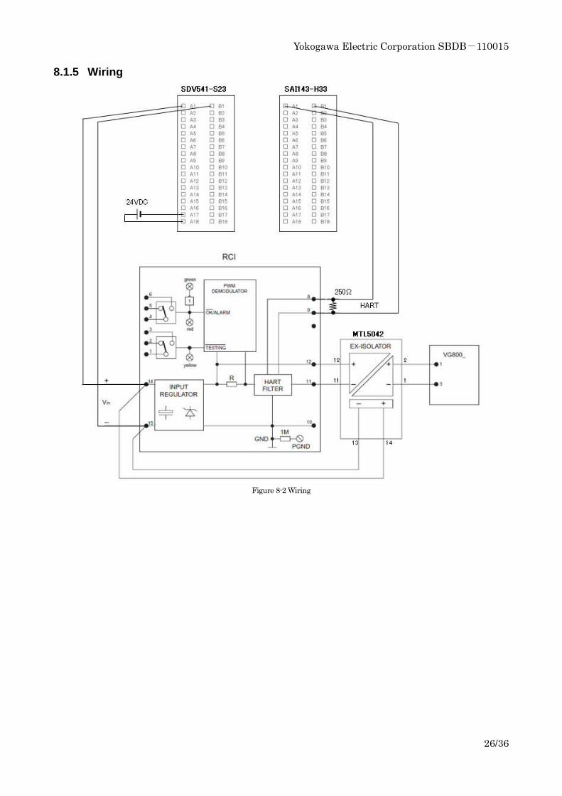
8.1.5 Wiring
Figure 8-2 Wiring
Yokogawa Electric Corporation SBDB-110015
27/36
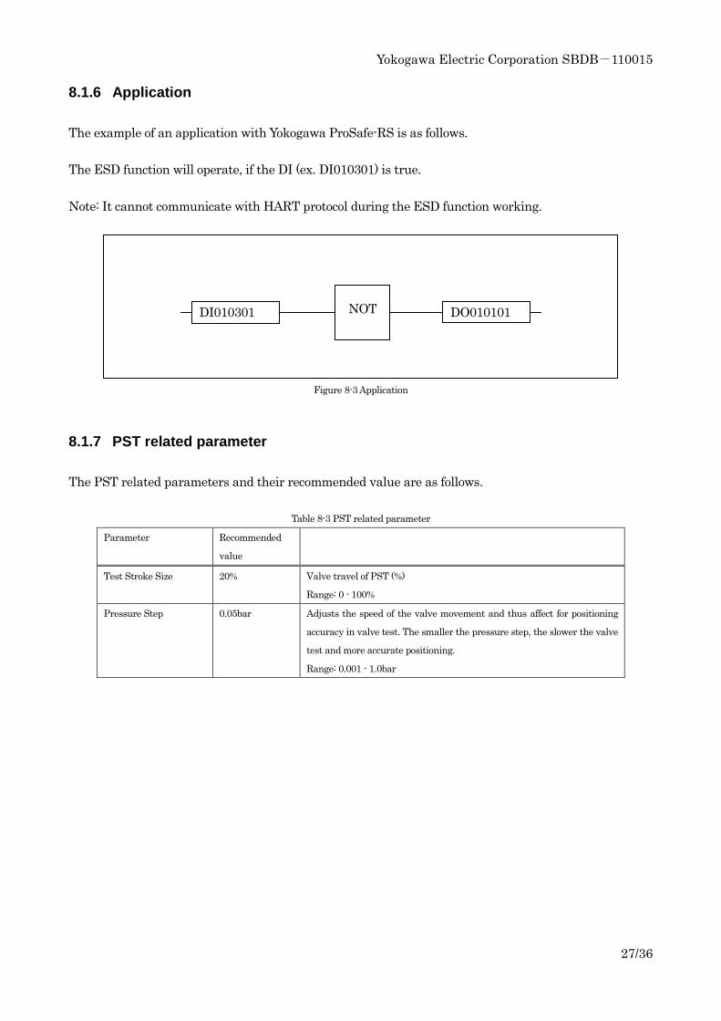
8.1.6 Application
The example of an application with Yokogawa ProSafe-RS is as follows.
The ESD function will operate, if the DI (ex. DI010301) is true.
Note: It cannot communicate with HART protocol during the ESD function working.
Figure 8-3 Application
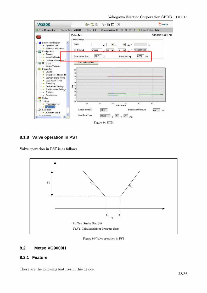
8.1.7 PST related parameter
The PST related parameters and their recommended value are as follows.
Table 8-3 PST related parameter
Parameter Recommended
value
Test Stroke Size 20% Valve travel of PST (%)
Range: 0 - 100%
Pressure Step 0.05bar Adjusts the speed of the valve movement and thus affect for positioning
accuracy in valve test. The smaller the pressure step, the slower the valve
test and more accurate positioning.
Range: 0.001 - 1.0bar
DI010301 DO010101 NOT
Yokogawa Electric Corporation SBDB-110015
28/36
Figure 8-4 DTM
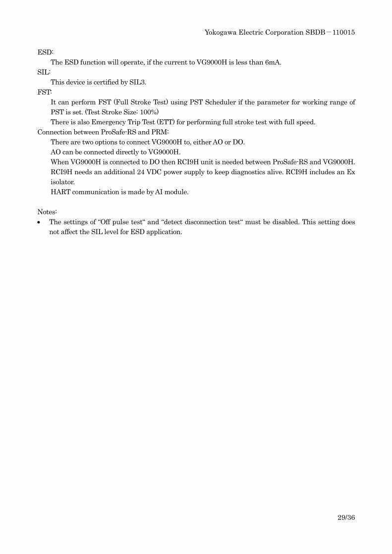
8.1.8 Valve operation in PST
Valve operation in PST is as follows.
Figure 8-5 Valve operation in PST
8.2 Metso VG9000H
8.2.1 Feature
There are the following features in this device.
T1
S1 V1 V1
S1: Test Stroke Size (%)
T1,V1: Calculated from Pressure Step
Yokogawa Electric Corporation SBDB-110015
29/36
ESD:
The ESD function will operate, if the current to VG9000H is less than 6mA.
SIL:
This device is certified by SIL3.
FST:
It can perform FST (Full Stroke Test) using PST Scheduler if the parameter for working range of
PST is set. (Test Stroke Size: 100%)
There is also Emergency Trip Test (ETT) for performing full stroke test with full speed.
Connection between ProSafe-RS and PRM:
There are two options to connect VG9000H to, either AO or DO.
AO can be connected directly to VG9000H.
When VG9000H is connected to DO then RCI9H unit is needed between ProSafe-RS and VG9000H.
RCI9H needs an additional 24 VDC power supply to keep diagnostics alive. RCI9H includes an Ex
isolator.
HART communication is made by AI module.
Notes:
• The settings of “Off pulse test“ and “detect disconnection test“ must be disabled. This setting does
not affect the SIL level for ESD application.
Yokogawa Electric Corporation SBDB-110015
30/36
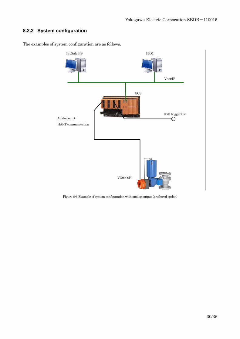
8.2.2 System configuration
The examples of system configuration are as follows.
Figure 8-6 Example of system configuration with analog output (preferred option)
ProSafe-RS PRM
ESD trigger Sw. Analog out +
HART communication
VG9000H
SCS
Vnet/IP
Yokogawa Electric Corporation SBDB-110015
31/36
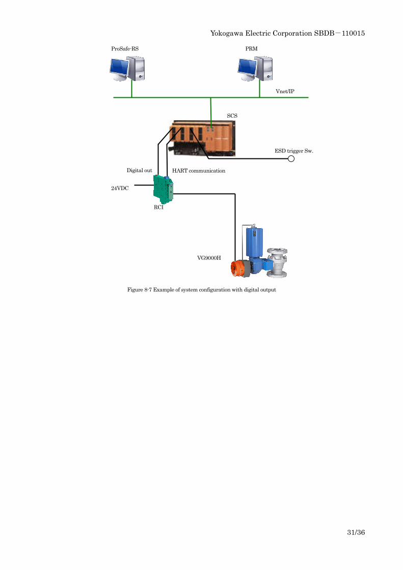
Figure 8-7 Example of system configuration with digital output
ProSafe-RS PRM
ESD trigger Sw.
Digital out HART communication
RCI
VG9000H
SCS
Vnet/IP
24VDC
Yokogawa Electric Corporation SBDB-110015
32/36
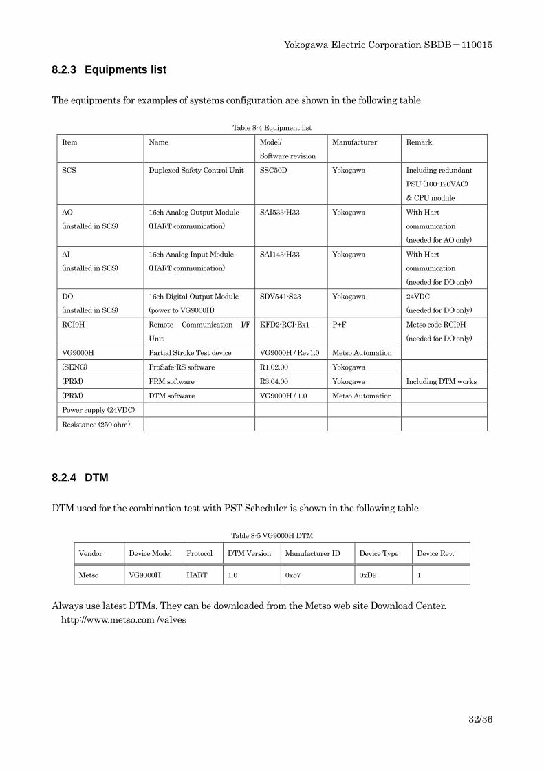
8.2.3 Equipments list
The equipments for examples of systems configuration are shown in the following table.
Table 8-4 Equipment list
Item Name Model/
Software revision
Manufacturer Remark
SCS
Duplexed Safety Control Unit SSC50D Yokogawa Including redundant
PSU (100-120VAC)
& CPU module
AO
(installed in SCS)
16ch Analog Output Module
(HART communication)
SAI533-H33 Yokogawa With Hart
communication
(needed for AO only)
AI
(installed in SCS)
16ch Analog Input Module
(HART communication)
SAI143-H33 Yokogawa With Hart
communication
(needed for DO only)
DO
(installed in SCS)
16ch Digital Output Module
(power to VG9000H)
SDV541-S23 Yokogawa 24VDC
(needed for DO only)
RCI9H Remote Communication I/F
Unit
KFD2-RCI-Ex1 P+F Metso code RCI9H
(needed for DO only)
VG9000H Partial Stroke Test device VG9000H / Rev1.0 Metso Automation
(SENG) ProSafe-RS software R1.02.00 Yokogawa
(PRM) PRM software R3.04.00 Yokogawa Including DTM works
(PRM) DTM software VG9000H / 1.0 Metso Automation
Power supply (24VDC)
Resistance (250 ohm)
8.2.4 DTM
DTM used for the combination test with PST Scheduler is shown in the following table.
Table 8-5 VG9000H DTM
Vendor Device Model Protocol DTM Version Manufacturer ID Device Type Device Rev.
Metso VG9000H HART 1.0 0x57 0xD9 1
Always use latest DTMs. They can be downloaded from the Metso web site Download Center.
http://www.metso.com /valves
Yokogawa Electric Corporation SBDB-110015
33/36
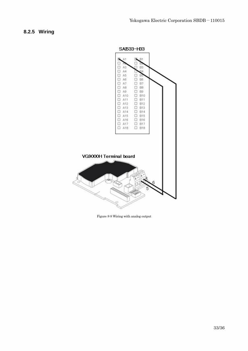
8.2.5 Wiring
Figure 8-8 Wiring with analog output
Yokogawa Electric Corporation SBDB-110015
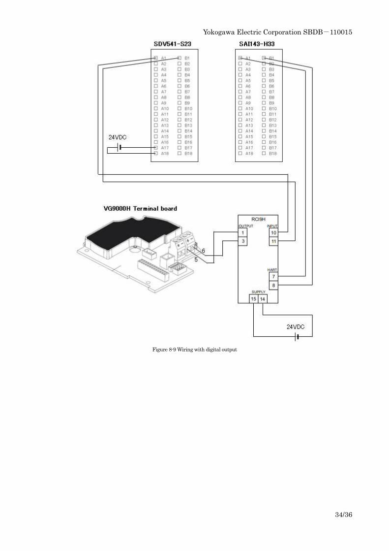
34/36
Figure 8-9 Wiring with digital output
Yokogawa Electric Corporation SBDB-110015
35/36
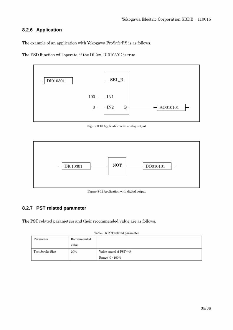
8.2.6 Application
The example of an application with Yokogawa ProSafe-RS is as follows.
The ESD function will operate, if the DI (ex. DI010301) is true.
Figure 8-10 Application with analog output
Figure 8-11 Application with digital output
8.2.7 PST related parameter
The PST related parameters and their recommended value are as follows.
Table 8-6 PST related parameter
Parameter Recommended
value
Test Stroke Size 20% Valve travel of PST (%)
Range: 0 - 100%
DI010301
AO010101
SEL_R
0
100 IN1
IN2 Q
DI010301 DO010101 NOT
Yokogawa Electric Corporation SBDB-110015
36/36
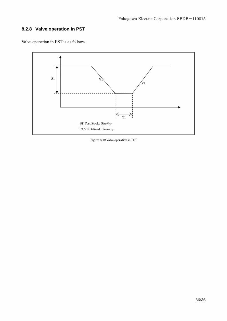
8.2.8 Valve operation in PST
Valve operation in PST is as follows.
Figure 8-12 Valve operation in PST
T1
S1 V1 V1
S1: Test Stroke Size (%)
T1,V1: Defined internally