Embed Size (px)
Citation preview
GeneralSpecifications
<<Contents>> <<Index>>
[Release 5]
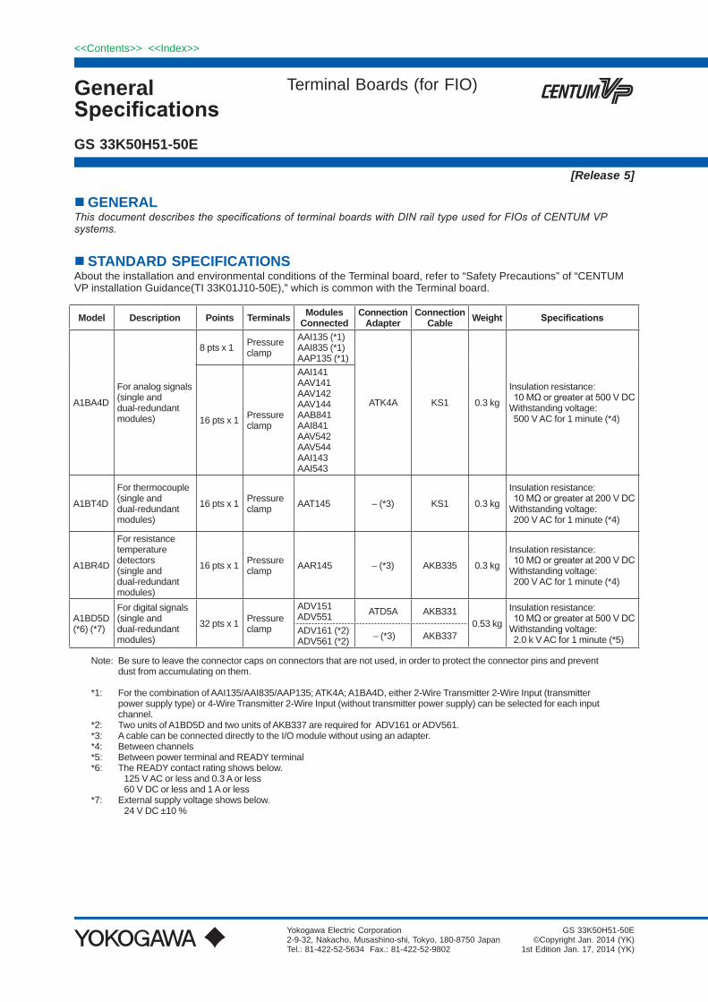
n GENERALThis document describes the specifications of terminal boards with DIN rail type used for FIOs of CENTUM VP systems.
n STANDARD SPECIFICATIONSAbout the installation and environmental conditions of the Terminal board, refer to “Safety Precautions” of “CENTUM VP installation Guidance(TI 33K01J10-50E),” which is common with the Terminal board.
Model Description Points Terminals Modules Connected
ConnectionAdapter
Connection Cable Weight Specifications
A1BA4D
For analog signals(single and dual-redundant modules)
8 pts x 1 Pressureclamp
AAI135 (*1)AAI835 (*1)AAP135 (*1)
ATK4A KS1 0.3 kg
Insulation resistance: 10MΩorgreaterat500VDCWithstanding voltage: 500 V AC for 1 minute (*4)16 pts x 1 Pressure
clamp
AAI141AAV141AAV142AAV144AAB841AAI841AAV542AAV544AAI143AAI543
A1BT4D
For thermocouple(single and dual-redundant modules)
16 pts x 1 Pressure clamp AAT145 – (*3) KS1 0.3 kg
Insulation resistance: 10MΩorgreaterat200VDCWithstanding voltage: 200 V AC for 1 minute (*4)
A1BR4D
For resistance temperature detectors(single and dual-redundant modules)
16 pts x 1 Pressureclamp AAR145 – (*3) AKB335 0.3 kg
Insulation resistance: 10MΩorgreaterat200VDCWithstanding voltage: 200 V AC for 1 minute (*4)
A1BD5D(*6) (*7)
For digital signals(single and dual-redundant modules)
32 pts x 1 Pressureclamp
ADV151ADV551 ATD5A AKB331
0.53 kg
Insulation resistance: 10MΩorgreaterat500VDCWithstanding voltage: 2.0 k V AC for 1 minute (*5)
ADV161 (*2) ADV561 (*2) – (*3) AKB337
Note: Be sure to leave the connector caps on connectors that are not used, in order to protect the connector pins and prevent dust from accumulating on them.
*1: For the combination of AAI135/AAI835/AAP135; ATK4A; A1BA4D, either 2-Wire Transmitter 2-Wire Input (transmitter power supply type) or 4-Wire Transmitter 2-Wire Input (without transmitter power supply) can be selected for each input channel.
*2: Two units of A1BD5D and two units of AKB337 are required for ADV161 or ADV561.*3: A cable can be connected directly to the I/O module without using an adapter.*4: Between channels*5: Between power terminal and READY terminal*6: The READY contact rating shows below. 125 V AC or less and 0.3 A or less 60 V DC or less and 1 A or less*7: External supply voltage shows below. 24 V DC ±10 %
Terminal Boards (for FIO)
Yokogawa Electric Corporation2-9-32, Nakacho, Musashino-shi, Tokyo, 180-8750 JapanTel.: 81-422-52-5634 Fax.: 81-422-52-9802
GS 33K50H51-50E
GS 33K50H51-50E©Copyright Jan. 2014 (YK)
1st Edition Jan. 17, 2014 (YK)
2
All Rights Reserved. Copyright © 2014, Yokogawa Electric Corporation
<<Contents>> <<Index>>
GS 33K50H50-50E Jan. 17, 2014-00
Regulatory ComplianceFor the detailed information of following standards, see “System Overview” (GS 33K01A10-50E).
Safety Standards[CAN/CSA-C22.2] No.61010-1[CE Marking] LVD
EMC Conformity Standards[CE Marking] EMC[C-Tick Marking][KC Marking]
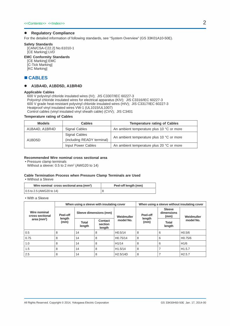
n CABLES A1BA4D, A1BD5D, A1BR4DApplicable Cables
600 V polyvinyl chloride insulated wires (IV); JIS C3307/IEC 60227-3Polyvinyl chloride insulated wires for electrical apparatus (KIV); JIS C3316/IEC 60227-3600 V grade heat-resistant polyvinyl chloride insulated wires (HIV); JIS C3317/IEC 60227-3Heatproof vinyl insulated wires VW-1 (UL1015/UL1007)Control cables (vinyl insulated vinyl sheath cable) (CVV); JIS C3401
Temperature rating of Cables
Models Cables Temperature rating of CablesA1BA4D, A1BR4D Signal Cables An ambient temperature plus 10 °C or more
A1BD5DSignal Cables(including READY terminal)
An ambient temperature plus 10 °C or more
Input Power Cables An ambient temperature plus 20 °C or more
Recommended Wire nominal cross sectional area• Pressure clamp terminals
Without a sleeve: 0.5 to 2 mm2 (AWG20 to 14)
Cable Termination Process when Pressure Clamp Terminals are Used• Without a Sleeve
Wire nominal cross sectional area (mm2) Peel-off length (mm)
0.5 to 2.5 (AWG20 to 14) 8
• With a Sleeve
Wire nominal cross sectional
area (mm2)
When using a sleeve with insulating cover When using a sleeve without insulating cover
Peel-off length (mm)
Sleeve dimensions (mm)Weidmuller model No.
Peel-off length (mm)
Sleeve dimensions
(mm) Weidmuller model No.
Totallength
Contact section length
Totallength
0.5 8 14 8 H0.5/14 8 6 H0.5/6
0.75 8 14 8 H0.75/14 8 6 H0.75/6
1.0 8 14 8 H1/14 8 6 H1/6
1.5 8 14 8 H1.5/14 8 7 H1.5.7
2.5 8 14 8 H2.5/14D 8 7 H2.5.7
3<<Contents>> <<Index>>
All Rights Reserved. Copyright © 2014, Yokogawa Electric Corporation GS 33K50H50-50E Jan. 17, 2014-00
A1BT4DApplicable Cables
600 V polyvinyl chloride insulated wires (IV); JIS C3307/IEC 60227-3Polyvinyl chloride insulated wires for electrical apparatus (KIV); JIS C3316/IEC 60227-3600 V grade heat-resistant polyvinyl chloride insulated wires (HIV); JIS C3317/IEC 60227-3Heatproof vinyl insulated wires VW-1 (UL1015/UL1007)Control cables (vinyl insulated vinyl sheath cable) (CVV); JIS C3401
Temperature rating of Cables
Models Cables Temperature rating of CablesA1BT4D Signal Cables An ambient temperature plus 10 °C or more
Recommended Wire nominal cross sectional area• Pressure clamp terminals
Without a sleeve: 0.5 to 2 mm2 (AWG20 to 14) With a sleeve: 0.5 to 1.5 mm2 (AWG20 to 16)
Cable Termination Process when Pressure Clamp Terminals are Used• Without a Sleeve
Wire nominal cross sectional area (mm2) Peel-off length (mm)
0.5 to 2 (AWG20 to 14) 11
• With a Sleeve
Wire nominal cross sectional
area (mm2)
When using a sleeve with insulating cover When using a sleeve without insulating cover
Peel-off length (mm)
Sleeve dimensions (mm)Weidmuller model No.
Peel-off length(mm)
Sleeve dimensions
(mm) Weidmuller model No.
Totallength
Contact section length
Totallength
0.5 11 16 10 H0.5/16 11 10 H0.5/10
0.75 11 16 10 H0.75/16 11 10 H0.75/10
1.0 11 16 10 H1/16 11 10 H1/10
1.25 to 1.5 11 16 10 H1.5/16 11 10 H1.5/10
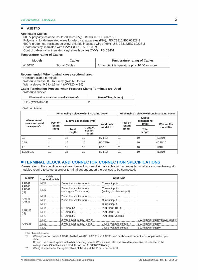
nTERMINAL BLOCK AND CONNECTOR CONNECTION SPECIFICATIONSPleaserefertothespecificationsshownbelowtoconnectsignalcableswithaproperterminalsincesomeAnalogI/Omodules require to select a proper terminal dependent on the devices to be connected.
Models Cable Connection Pris Input Type
AAI141 AAI143 AAI841 (*1)
INA 2-wire transmitter input + Current input -
–INB 2-wire transmitter input -
(setting pin: 2-wire input)Current input + (setting pin: 4-wire input)
AAI135 AAI835
INA 2-wire transmitter input + ––INB 2-wire transmitter input - Current input +
INC – Current input -
AAR145 (*2)
INA RTD input A POT input, 100 % –INB RTD input B POT input, 0 %
INC RTD input B POT input, variable
AAP135 INA 2-wire power supply (power) – 3-wire power supply power supply INB 2-wire power supply (signal) 2-wire (voltage, contact) + 3-wire power supply + INC – 2-wire (voltage, contact) - 3-wire power supply -
is channel number.*1: When power of models AAI141, AAI143, AAI841, AAI135 and AAI835 is off or abnormal, current input loop is in the open
state. Do not use current signals with other receiving devices.When in use, also use an extarnal receiver resistance, in the voltage mode (Shunt resistant module part no.: A1080RZ 250 ohm).
*2: Wiring resistance for the signal cables of INA and INB must be identical.
4
All Rights Reserved. Copyright © 2014, Yokogawa Electric Corporation
<<Contents>> <<Index>>
GS 33K50H50-50E Jan. 17, 2014-00
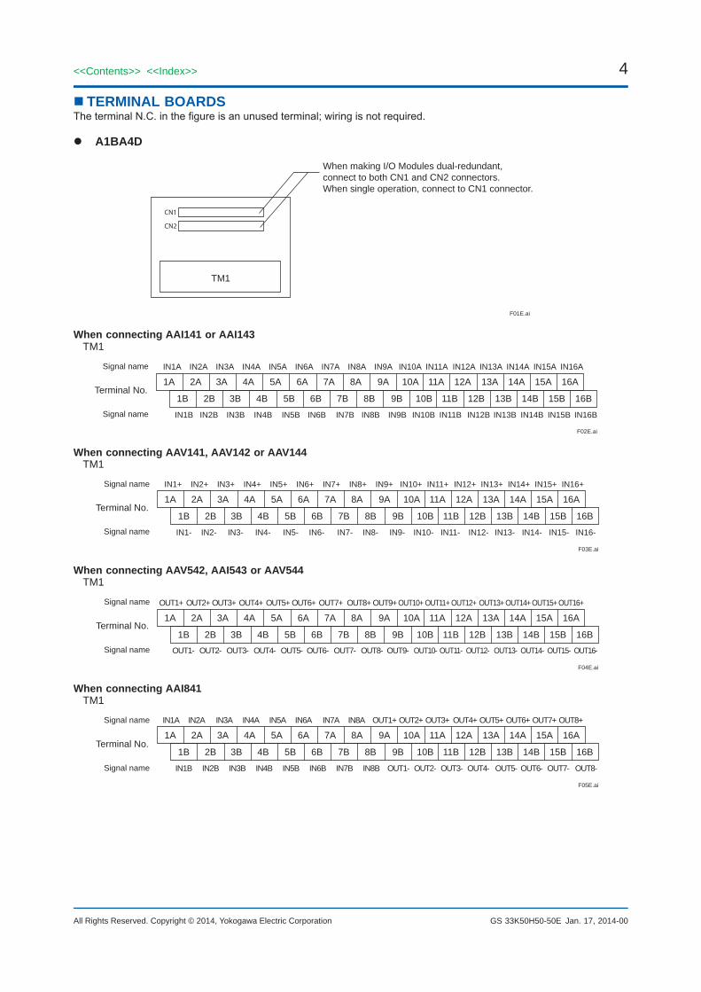
n TERMINAL BOARDSTheterminalN.C.inthefigureisanunusedterminal;wiringisnotrequired.
A1BA4D
F01E.ai
TM1
When making I/O Modules dual-redundant,connect to both CN1 and CN2 connectors.When single operation, connect to CN1 connector.
CN1
CN2
When connecting AAI141 or AAI143TM1
F02E.ai
1A 2A 3A 4A 5A 6A 7A 8A 9A 10A 11A 12A 13A 14A 15A 16A IN1A IN2A IN3A IN4A IN5A IN6A IN7A IN8A IN9A IN10A IN11A IN12A IN13A IN14A IN15A IN16A
IN1B IN2B IN3B IN4B IN5B IN6B IN7B IN8B IN9B IN10B IN11B IN12B IN13B IN14B IN15B IN16B
1B
Signal name
Signal name
Terminal No. 2B 3B 4B 5B 6B 7B 8B 9B 10B 11B 12B 13B 14B 15B 16B
When connecting AAV141, AAV142 or AAV144TM1
F03E.ai
1A 2A 3A 4A 5A 6A 7A 8A 9A 10A 11A 12A 13A 14A 15A 16A IN1+ IN2+ IN3+ IN4+ IN5+ IN6+ IN7+ IN8+ IN9+ IN10+ IN11+ IN12+ IN13+ IN14+ IN15+ IN16+
IN1- IN2- IN3- IN4- IN5- IN6- IN7- IN8- IN9- IN10- IN11- IN12- IN13- IN14- IN15- IN16-
1B
Signal name
Signal name
Terminal No. 2B 3B 4B 5B 6B 7B 8B 9B 10B 11B 12B 13B 14B 15B 16B
When connecting AAV542, AAI543 or AAV544TM1
F04E.ai
1A 2A 3A 4A 5A 6A 7A 8A 9A 10A 11A 12A 13A 14A 15A 16A OUT1+ OUT2+ OUT3+ OUT4+ OUT5+ OUT6+ OUT7+ OUT8+ OUT9+ OUT10+ OUT11+ OUT12+ OUT13+OUT14+OUT15+OUT16+
OUT1- OUT2- OUT3- OUT4- OUT5- OUT6- OUT7- OUT8- OUT9- OUT10- OUT11- OUT12- OUT13- OUT14- OUT15- OUT16-
1B 2B 3B 4B 5B 6B 7B 8B 9B 10B 11B 12B 13B 14B 15B 16B
Signal name
Signal name
Terminal No.
When connecting AAI841TM1
F05E.ai
1A 2A 3A 4A 5A 6A 7A 8A 9A 10A 11A 12A 13A 14A 15A 16A IN1A IN2A IN3A IN4A IN5A IN6A IN7A IN8A OUT1+ OUT2+ OUT3+ OUT4+ OUT5+ OUT6+ OUT7+ OUT8+
IN1B IN2B IN3B IN4B IN5B IN6B IN7B IN8B OUT1- OUT2- OUT3- OUT4- OUT5- OUT6- OUT7- OUT8-
1B
Signal name
Signal name
Terminal No. 2B 3B 4B 5B 6B 7B 8B 9B 10B 11B 12B 13B 14B 15B 16B
5<<Contents>> <<Index>>
All Rights Reserved. Copyright © 2014, Yokogawa Electric Corporation GS 33K50H50-50E Jan. 17, 2014-00
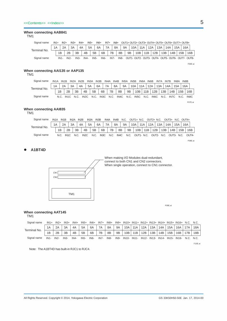
When connecting AAB841TM1
F06E.ai
1A 2A 3A 4A 5A 6A 7A 8A 9A 10A 11A 12A 13A 14A 15A 16A IN1+ IN2+ IN3+ IN4+ IN5+ IN6+ IN7+ IN8+
IN1- IN2- IN3- IN4- IN5- IN6- IN7- IN8-
1B 2B 3B 4B 5B 6B 7B 8B 9B 10B 11B 12B 13B 14B 15B 16B
OUT1+ OUT2+ OUT3+ OUT4+ OUT5+ OUT6+ OUT7+ OUT8+
OUT1- OUT2- OUT3- OUT4- OUT5- OUT6- OUT7- OUT8-
Signal name
Signal name
Terminal No.
When connecting AAI135 or AAP135TM1
F07E.ai
1A 2A 3A 4A 5A 6A 7A 8A 9A 10A 11A 12A 13A 14A 15A 16A IN1A IN2A IN3A IN4AIN1B IN2B IN3B IN4B IN5A IN6A IN7A IN8AIN5B IN6B IN7B IN8B
1B
Signal name
Signal name
Terminal No. 2B 3B 4B 5B 6B 7B 8B 9B 10B 11B 12B 13B 14B 15B 16B
IN1C N.C. IN2C N.C. IN3C N.C IN4C N.C. IN5C N.C. IN6C N.C. IN7C N.C. IN8CN.C.
When connecting AAI835TM1
F08E.ai
1A 2A 3A 4A 5A 6A 7A 8A 9A 10A 11A 12A 13A 14A 15A 16AIN1A IN2A IN3A IN4A IN4BIN1B IN2B IN3B
1B
Signal name
Signal name
Terminal No.2B 3B 4B 5B 6B 7B 8B 9B 10B 11B 12B 13B 14B 15B 16B
IN1C N.C. IN2C N.C. IN3C N.C IN4CN.C.
N.C. N.C. N.C. N.C.OUT1+ OUT2+ OUT3+ OUT4+
OUT1- N.C.N.C. OUT2- N.C. OUT3- N.C. OUT4-
A1BT4D
F09E.ai
TM1
When making I/O Modules dual-redundant,connect to both CN1 and CN2 connectors.When single operation, connect to CN1 connector.
CN1
CN2
When connecting AAT145 TM1
F10E.ai
1A 2A 3A 4A 5A 6A 7A 8A 9A 10A 11A 12A 13A 14A 15A 16A 17A 18A IN1+ IN2+ IN3+ IN4+ IN5+ IN6+ IN7+ IN8+ IN9+ IN10+ IN11+ IN12+ IN13+ IN14+ IN15+ IN16+ N.C. N.C.
IN1- IN2- IN3- IN4- IN5- IN6- IN7- IN8- IN9- IN10- IN11- IN12- IN13- IN14- IN15- IN16- N.C. N.C.
1B
Signal name
Signal name
Terminal No. 2B 3B 4B 5B 6B 7B 8B 9B 10B 11B 12B 13B 14B 15B 16B 17B 18B
Note: The A1BT4D has built-in RJC1 to RJC4.
6
All Rights Reserved. Copyright © 2014, Yokogawa Electric Corporation
<<Contents>> <<Index>>
GS 33K50H50-50E
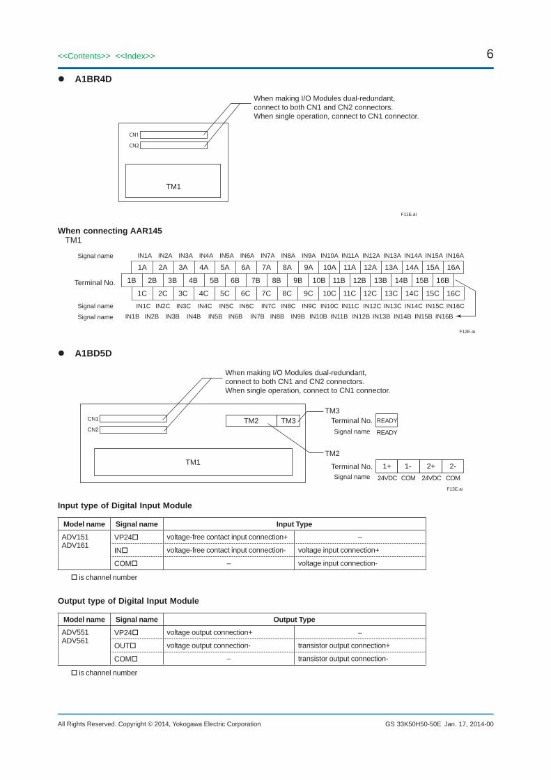
A1BR4D
F11E.ai
TM1
When making I/O Modules dual-redundant,connect to both CN1 and CN2 connectors.When single operation, connect to CN1 connector.
CN1
CN2
When connecting AAR145TM1
F12E.ai
Terminal No. 1B 2B 3B 4B 5B 6B 7B 8B 9B 10B 11B 12B 13B 14B 15B 16B
IN1C IN2C IN3C IN4C IN5C IN6C IN7C IN8C IN9C IN10C IN11C IN12C IN13C IN14C IN15C IN16C IN1B IN2B IN3B IN4B IN5B IN6B IN7B IN8B IN9B IN10B IN11B IN12B IN13B IN14B IN15B IN16B
1C
1A 2A 3A 4A 5A 6A 7A 8A 9A 10A 11A 12A 13A 14A 15A 16A IN1A IN2A IN3A IN4A IN5A IN6A IN7A IN8A IN9A IN10A IN11A IN12A IN13A IN14A IN15A IN16A
Signal name
Signal name
Signal name
2C 3C 4C 5C 6C 7C 8C 9C 10C 11C 12C 13C 14C 15C 16C
A1BD5D
F13E.ai
TM1
TM2 TM3TM3
When making I/O Modules dual-redundant,connect to both CN1 and CN2 connectors.When single operation, connect to CN1 connector.
CN1
CN2
TM2
Terminal No.
Terminal No.
READY
READY
2+ 2-1+ 1-24VDC COM COM24VDCSignal name
Signal name
Input type of Digital Input Module
Model name Signal name Input TypeADV151ADV161
VP24 voltage-free contact input connection+ –
IN voltage-free contact input connection- voltage input connection+
COM – voltage input connection-
is channel number
Output type of Digital Input Module
Model name Signal name Output TypeADV551ADV561
VP24 voltage output connection+ –
OUT voltage output connection- transistor output connection+
COM – transistor output connection-
is channel number
Jan. 17, 2014-00
7<<Contents>> <<Index>>
All Rights Reserved. Copyright © 2014, Yokogawa Electric Corporation GS 33K50H50-50E
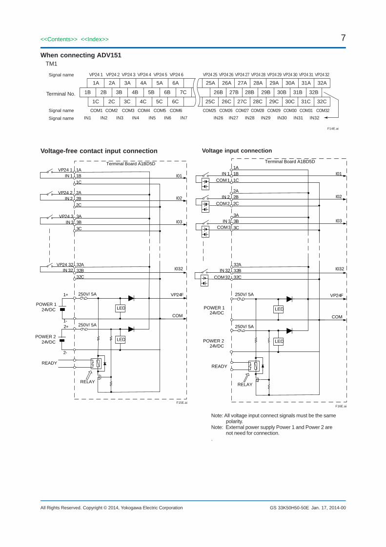
When connecting ADV151TM1
F14E.ai
Terminal No. 1B 2B 3B 4B 5B 6B 7C 26B 27B 28B 29B 30B 31B 32B
COM1 COM2 COM3 COM4 COM5 COM6 COM25 COM26 COM27 COM28 COM29 COM30 COM31 COM32IN1 IN2 IN3 IN4 IN5 IN6 IN7 IN26 IN27 IN28 IN29 IN30 IN31 IN32
1C
1A 2A 3A 4A 5A 6A 25A 26A 27A 28A 29A 30A 31A 32AVP24 1 VP24 2 VP24 3 VP24 4 VP24 5 VP24 6 VP24 25 VP24 26 VP24 27 VP24 28 VP24 29 VP24 30 VP24 31 VP24 32
Signal name
Signal name
Signal name
2C 3C 4C 5C 6C 25C 26C 27C 28C 29C 30C 31C 32C
Voltage-free contact input connection
F15E.ai
1+
1-
Terminal Board A1BD5D
POWER 1 24VDC
2+
2-
READY
1A1B1C
2A2B2C
3A3B3C
32A32B32C
250V/ 5A
250V/ 5A
LED
LED
I01
I02
I03
I032
VP24 1IN 1
VP24 2IN 2
VP24 3IN 3
VP24 32IN 32
VP24F
COM
RELAY
POWER 2 24VDC
Voltage input connection
F16E.ai
250V/ 5A
250V/ 5A
READY
1A1B1C
2A2B2C
3A3B3C
32A32B32C
LED
LED
I01
I02
I03
I032
COM 1IN 1
COM 2IN 2
COM 3IN 3
COM 32IN 32
VP24F
COM
RELAY
24VDC
24VDC
POWER 1
POWER 2
Terminal Board A1BD5D
Note: All voltage input connect signals must be the same polarity.
Note: External power supply Power 1 and Power 2 are not need for connection.
.
Jan. 17, 2014-00
8
All Rights Reserved. Copyright © 2014, Yokogawa Electric Corporation
<<Contents>> <<Index>>
GS 33K50H50-50E
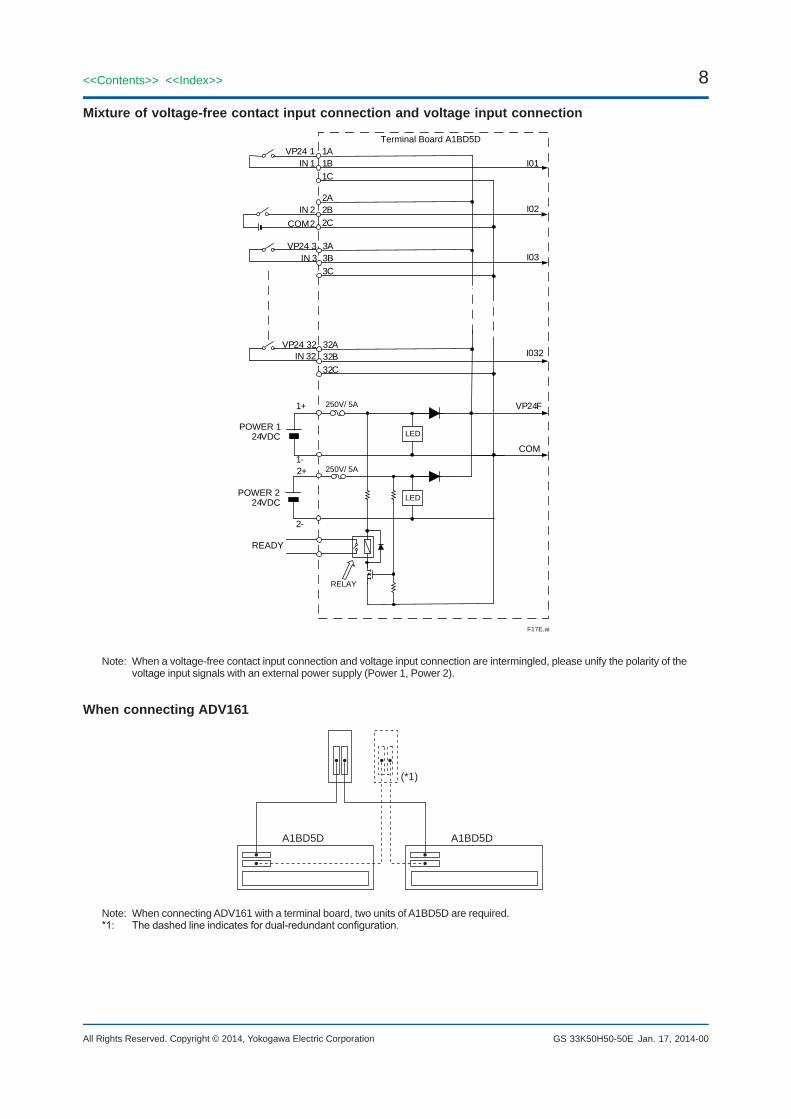
Mixture of voltage-free contact input connection and voltage input connection
F17E.ai
1+
1-
250V/ 5A
250V/ 5A
24VDC
2+
2-
READY
1A1B1C
2A2B2C
3A3B3C
32A32B32C
LED
LED
I01
I02
I03
I032
VP24 1IN 1
IN 2
VP24 3IN 3
VP24 32IN 32
VP24F
COM
RELAY
24VDC
COM 2
POWER 1
POWER 2
Terminal Board A1BD5D
Note: When a voltage-free contact input connection and voltage input connection are intermingled, please unify the polarity of the voltage input signals with an external power supply (Power 1, Power 2).
When connecting ADV161
A1BD5D
F18E.ai
(*1)
A1BD5D
Note: When connecting ADV161 with a terminal board, two units of A1BD5D are required.*1: Thedashedlineindicatesfordual-redundantconfiguration.
Jan. 17, 2014-00
9<<Contents>> <<Index>>
All Rights Reserved. Copyright © 2014, Yokogawa Electric Corporation GS 33K50H50-50E
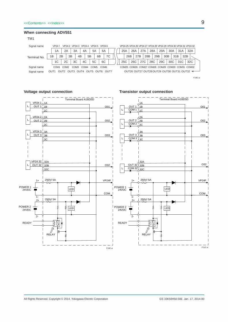
When connecting ADV551TM1
F19E.ai
Terminal No. 1B 2B 3B 4B 5B 6B 7C 26B 27B 28B 29B 30B 31B 32B
COM1 COM2 COM3 COM4 COM5 COM6 COM25 COM26 COM27 COM28 COM29 COM30 COM31 COM32
OUT1 OUT2 OUT3 OUT4 OUT5 OUT6 OUT7 OUT26 OUT27 OUT28 OUT29 OUT30 OUT31 OUT32
1C
1A 2A 3A 4A 5A 6A 25A 26A 27A 28A 29A 30A 31A 32AVP24 1 VP24 2 VP24 3 VP24 4 VP24 5 VP24 6 VP24 25 VP24 26 VP24 27 VP24 28 VP24 29 VP24 30 VP24 31 VP24 32
Signal name
Signal name
Signal name
2C 3C 4C 5C 6C 25C 26C 27C 28C 29C 30C 31C 32C
Voltage output connection
F20E.ai
1+
1-
250V/ 5A
250V/ 5A
24VDC
2+
2-
READY
1A1B1C
2A2B2C
3A3B3C
32A32B32C
LED
LED
O01
O02
O03
O32
VP24 1OUT 1
VP24 2OUT 2
VP24 3OUT 3
VP24 32OUT 32
VP24F
COM
RELAY
24VDC
L
L
L
L
Terminal Board A1BD5D
POWER 1
POWER 2
Transistor output connection
F21E.ai
1+
1-
250V/ 5A
250V/ 5A
24VDC
2+
2-
READY
1A1B1C
2A2B2C
3A3B3C
32A32B32C
LED
LED
O01
O02
O03
O32COM 32OUT 32
VP24F
COM
RELAY
24VDC
L
COM 3OUT 3
L
COM 2OUT 2
L
LOUT 1COM 1
Terminal Board A1BD5D
POWER 1
POWER 2
Jan. 17, 2014-00
10
All Rights Reserved. Copyright © 2014, Yokogawa Electric Corporation
<<Contents>> <<Index>>
GS 33K50H50-50E
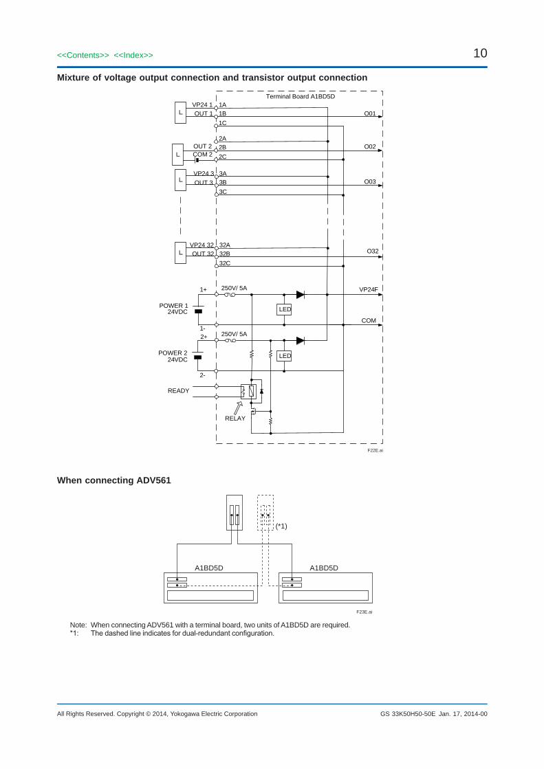
Mixture of voltage output connection and transistor output connection
F22E.ai
1+
1-
250V/ 5A
250V/ 5A
24VDC
2+
2-
READY
1A1B1C
2A2B2C
3A3B3C
32A32B32C
LED
LED
O01
O02
O03
O32
VP24 1OUT 1
VP24 3OUT 3
VP24 32OUT 32
VP24F
COM
RELAY
24VDC
L
L
L
COM 2OUT 2
L
Terminal Board A1BD5D
POWER 1
POWER 2
When connecting ADV561
A1BD5D
F23E.ai
(*1)
A1BD5D
Note: When connecting ADV561 with a terminal board, two units of A1BD5D are required.*1: Thedashedlineindicatesfordual-redundantconfiguration.
Jan. 17, 2014-00
11<<Contents>> <<Index>>
All Rights Reserved. Copyright © 2014, Yokogawa Electric Corporation GS 33K50H50-50E
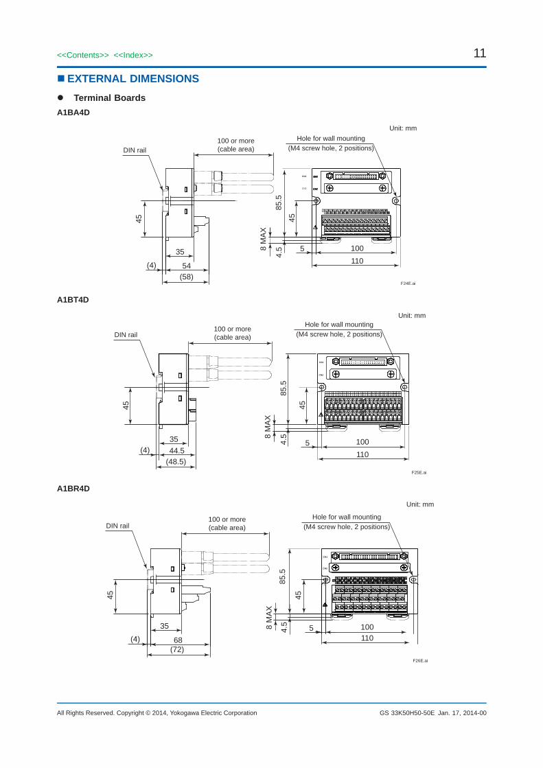
n EXTERNAL DIMENSIONS Terminal BoardsA1BA4D
F24E.ai
45
54
35
(58)(4)
100110
45
4.58
MA
X
85.5
5
CN1
CN2
Unit: mmHole for wall mounting
(M4 screw hole, 2 positions)100 or more(cable area)DIN rail
A1BT4D
F25E.ai
45
44.535
(48.5)(4)
100110
45
4.5
85.5
8 M
AX
5
Unit: mmHole for wall mounting
(M4 screw hole, 2 positions)100 or more(cable area)DIN rail
CN1
CN2
1A 2A 3A 4A 5A 6A 7A 8A1B 2B 3B 4B 5B 6B 7B 8B
9A 10A 11A 12A 13A 14A 15A 16A9B 10B 11B 12B 13B 14B 15B 16B
17A 18A17B 18B
A1BR4D
F26E.ai
45
68
35
(72)(4)
100110
45
85.5
54.58 M
AX
CN1
CN2
Unit: mm
Hole for wall mounting(M4 screw hole, 2 positions)
100 or more(cable area)DIN rail
Jan. 17, 2014-00
12
All Rights Reserved. Copyright © 2014, Yokogawa Electric Corporation
<<Contents>> <<Index>>
GS 33K50H50-50E
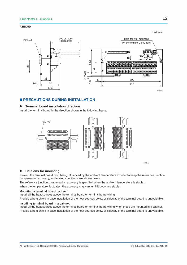
A1BD5D
F27E.ai
Unit: mm
45
6835
(72)(4)
100 or more(cable area)DIN rail
200210
4585
.5
5
Hole for wall mounting( M4 screw hole, 2 positions)
8 M
AX
4.5
CN1
CN2
32A
n PRECAUTIONS DURING INSTALLATION Terminal board installation directionInstalltheterminalboardinthedirectionshowninthefollowingfigure.
F28E.ai
DIN rail
Cautions for mountingPreventtheterminalboardfrombeinginfluencedbytheambienttemperatureinordertokeepthereferencejunctioncompensation accuracy, as detailed conditions are shown below.Thereferencejunctioncompensationaccuracyisspecifiedwhentheambienttemperatureisstable.Whenthetemperaturefluctuates,theaccuracymayvaryuntilitbecomesstable.
Mounting a terminal board by itselfInstall all the heat sources above the terminal board or terminal board wiring.Provide a heat shield in case installation of the heat sources below or sideway of the terminal board is unavoidable.
Installing terminal board in a cabinetInstall all the heat sources above the terminal board or terminal board wiring when those are mounted in a cabinet.Provide a heat shield in case installation of the heat sources below or sideway of the terminal board is unavoidable.
Jan. 17, 2014-00
13<<Contents>> <<Index>>
All Rights Reserved. Copyright © 2014, Yokogawa Electric Corporation GS 33K50H50-50E
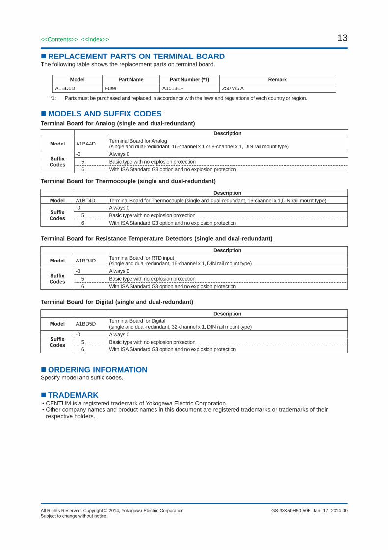
n REPLACEMENT PARTS ON TERMINAL BOARDThe following table shows the replacement parts on terminal board.
Model Part Name Part Number (*1) RemarkA1BD5D Fuse A1513EF 250 V/5 A
*1: Parts must be purchased and replaced in accordance with the laws and regulations of each country or region.
n MODELS AND SUFFIX CODESTerminal Board for Analog (single and dual-redundant)
Description
Model A1BA4D Terminal Board for Analog (single and dual-redundant, 16-channel x 1 or 8-channel x 1, DIN rail mount type)
Suffix Codes
-0 Always 0 5 Basic type with no explosion protection 6 With ISA Standard G3 option and no explosion protection
Terminal Board for Thermocouple (single and dual-redundant)
Description Model A1BT4D Terminal Board for Thermocouple (single and dual-redundant, 16-channel x 1,DIN rail mount type)
Suffix Codes
-0 Always 0 5 Basic type with no explosion protection 6 With ISA Standard G3 option and no explosion protection
Terminal Board for Resistance Temperature Detectors (single and dual-redundant)
Description
Model A1BR4D Terminal Board for RTD input(single and dual-redundant, 16-channel x 1, DIN rail mount type)
Suffix Codes
-0 Always 0 5 Basic type with no explosion protection 6 With ISA Standard G3 option and no explosion protection
Terminal Board for Digital (single and dual-redundant)
Description
Model A1BD5D Terminal Board for Digital (single and dual-redundant, 32-channel x 1, DIN rail mount type)
Suffix Codes
-0 Always 0 5 Basic type with no explosion protection 6 With ISA Standard G3 option and no explosion protection
n ORDERING INFORMATIONSpecifymodelandsuffixcodes.
n TRADEMARK• CENTUM is a registered trademark of Yokogawa Electric Corporation.• Other company names and product names in this document are registered trademarks or trademarks of their
respective holders.
Subjecttochangewithoutnotice.Jan. 17, 2014-00