Embed Size (px)
Citation preview
97/08
MAINS BATTERY CHARGER NETZLADEGERÄT
NLG4
USER'S MANUAL BETRIEBSANLEITUNG
BRUSA ELEKTRONIK TEL ++41 81 750 35 30 CH - 9473 GAMS FAX ++41 81 750 35 39
NLG4 2
Table of contents
page
1. Introduction................................3 2. Types available ..........................4 3. Operating principle....................5 4. Charging characteristics ...........6 5. Connections and wiring .............8 Minimum wiring requirements .................8
Position, type and function of connections9
6. Additional functions .................10 Adjusting the maximum current input ....10
Battery temperature sensors...................12
Universal control inputs.........................13
Status indicator ......................................14
Indication of charging status..................15
16
"Drive" switch input...............................17
7. Technical data..........................18 Inputs and outputs-specifications...........20
Protective circuits and safety features ...22
General characteristics ..........................24
Control interfaces...................................26
RS-232 interface.....................................26
Connections............................................28
Power characteristics.............................29
Schematic diagram.................................30
Connector ...............................................31
Mains plug..............................................32
Inhaltsverzeichnis
Seite
1. Einführung ................................. 3 2. Typenübersicht........................... 4 3. Wirkungsweise........................... 5 4. Ladekennlinie............................. 6 5. Anschlüsse ................................. 8 Minimalverdrahtung ................................ 8
Position, Form und Funktion der An-schlüsse........................................... 9
6. Zusatzfunktionen ..................... 10 Einstellung des maximalen Netzstromes10
Batterie - Temperatursensoren............... 12
Universelle Eingänge............................. 13
Statusanzeige ......................................... 14
Ladezustandsanzeige ............................. 15
Hauptschalter ......................................... 16
Fahrschalter-Eingang ............................. 17
7. Technische Daten..................... 19 Eingangs - und Ausgangsspezifikationen21
Schutzfunktionen ................................... 23
allgemeine Eigenschaften ...................... 25
Kontroll-Interface .................................. 27
RS-232-Schnittstelle .............................. 27
Anschlüsse ............................................. 28
Leistungskurven..................................... 29
Schaltschema ......................................... 30
Stecker ................................................... 31
Netz Stecker........................................... 32
NLG4 3
1. Introduction
Life of the main batteries and reliability of the vehicle’s drive system depend, to a very great extent, on the battery charger. The NLG-4 was thus developed specially as a mobile charging unit suitable for all bat-tery types presently in use and to support all currently known charging characteris-tics.
Integration of the charger in the vehicle's existing overall concept is greatly simpli-fied by its built-in serial interface (RS-232). All relevant battery and mains supply data can be accessed, as required, through this interface.
The NLG-4's compact design and low weight (less than 7.3 kg for 3.3kW) are fea-tures particularly appreciated by vehicle manufacturers.
1. Einführung
Die Standzeit des Fahrbatteriesatzes und die Zuverlässigkeit der Antriebseinheit hängen in hohem Mass vom Netzladegerät ab. Das NLG-4 ist deshalb speziell für den mobilen Einsatz entwickelt worden und unterstützt alle derzeit bekannten Akkumu-latortechnologien und Ladekennlinien.
Die eingebaute serielle Schnittstelle (RS-232) erleichtert die Integration des Ladege-rätes in ein bestehendes Gesamtkonzept. Bei Bedarf stehen alle relevanten Batterie- und Netzdaten an dieser Schnittstelle ab-rufbereit.
Der kompakte Aufbau und die geringe Ge-samtmasse (unter 7.3 kg für 3,3kW Lade-leistung) kommen den Wünschen der Fahr-zeughersteller in besonderer Weise entge-gen.
NLG4 4
2. Types available
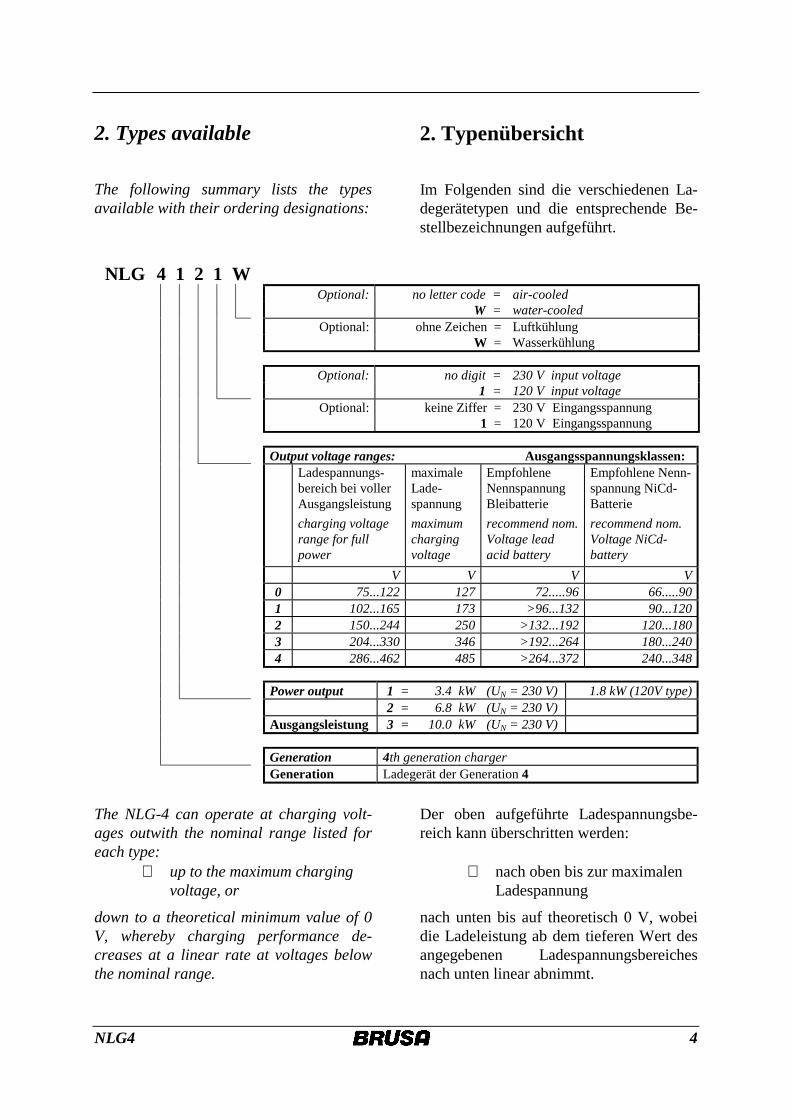
The following summary lists the types available with their ordering designations:
2. Typenübersicht
Im Folgenden sind die verschiedenen La-degerätetypen und die entsprechende Be-stellbezeichnungen aufgeführt.
NLG 4 1 2 1 W Optional: no letter code = air-cooled W = water-cooled Optional: ohne Zeichen = Luftkühlung W = Wasserkühlung Optional: no digit = 230 V input voltage 1 = 120 V input voltage Optional: keine Ziffer = 230 V Eingangsspannung 1 = 120 V Eingangsspannung
Output voltage ranges: Ausgangsspannungsklassen: Ladespannungs-
bereich bei voller Ausgangsleistung charging voltage range for full power
maximale Lade-spannung maximum charging voltage
Empfohlene Nennspannung Bleibatterie recommend nom. Voltage lead acid battery
Empfohlene Nenn-spannung NiCd-Batterie recommend nom. Voltage NiCd-battery
V V V V 0 75...122 127 72.....96 66.....90 1 102...165 173 >96...132 90...120 2 150...244 250 >132...192 120...180 3 204...330 346 >192...264 180...240 4 286...462 485 >264...372 240...348
Power output 1 = 3.4 kW (UN = 230 V) 1.8 kW (120V type) 2 = 6.8 kW (UN = 230 V)
Ausgangsleistung 3 = 10.0 kW (UN = 230 V) Generation 4th generation charger Generation Ladegerät der Generation 4
The NLG-4 can operate at charging volt-ages outwith the nominal range listed for each type:
⇒ up to the maximum charging voltage, or
down to a theoretical minimum value of 0 V, whereby charging performance de-creases at a linear rate at voltages below the nominal range.
Der oben aufgeführte Ladespannungsbe-reich kann überschritten werden:
⇒ nach oben bis zur maximalen Ladespannung
nach unten bis auf theoretisch 0 V, wobei die Ladeleistung ab dem tieferen Wert des angegebenen Ladespannungsbereiches nach unten linear abnimmt.
NLG4 5
3. Operating principle
The charger (3.3 kW version) operates from a single-phase AC current supply and complies with applicable standards and regulations. The battery remains potential-free during charging. Other points particu-larly worthy of mention in this respect are the charger's sinus-form current input curve and cos ϕ value of 0.98, which allow full advantage to be taken of the maximum permitted power output from the single-phase supply. This is limited to approx. 3.6 kW in most European countries with a mains voltage of 230 V and maximum per-mitted current output of 16A. In countries where the power rating is lower (10A in Switzerland) or where, for other reasons, the circumstances for connecting the charger to the mains supply are not ideal (low fuse rating or other power consum-ers), charging output can be adjusted infi-nitely to suit the prevailing conditions. The NLG-4 is also capable of operating from 120V mains supplies (USA, parts of north-ern Europe, on ships) without adjustments having to be made. Power output, however, is then lower (resistance characteristics).
Basically speaking, the NLG-4 is a pri-mary-frequency mode-switching power supply unit based on the resonant con-verter operating principle. Efficiency of the charger is rated at 92%, making a fully-enclosed, compact design possible. As a result of its operating frequency of up to 60 kHz, the advanced design of the output stage and the use of special filter elements, all phases of the charging procedure are virtually noiseless.
3. Wirkungsweise
Das Gerät (3.3 kW Version) arbeitet am einphasigen Wechselstromnetz und erfüllt dabei die massgeblichen Normen und Vor-schriften. Während des Ladevorganges bleibt die Batterie potentialfrei. In diesem Zusammenhang sind die sinusförmige Stromaufnahme und der cos phi von 0.98 besonders hervorzuheben, weil dadurch die maximal zulässige Anschlussleistung am Einphasennetz voll ausgeschöpft werden kann. Diese beträgt in den meisten europä-ischen Ländern mit 230 V Nennspannung und maximal zulässigen Strom von 16A rund 3,6 kW. In Ländern mit geringerer Anschlussleistung (Schweiz 10 A) oder bei nicht optimalen Anschlussbedingungen (schwächere Netzsicherung, Neben-verbraucher) kann die Ladeleistung stufen-los den gegebenen Verhältnissen angepasst werden. Das NLG-4 lädt ohne Umschal-tung auch von 120V Netzen (USA, Teile Nordeuropas, auf Schiffen), setzt dann al-lerdings nicht mehr soviel Leistung um (Widerstandscharakteristik).
Das Gerät ist im wesentlichen ein primär-getaktetes Schaltnetzteil und basiert auf dem Resonanzwandlerprinzip. Der gute Wirkungsgrad von über 92% ermöglicht eine kompakte und rundum geschlossene Bauweise. Bedingt durch die Arbeitsfre-quenz von bis zu 60 kHz, die Verwendung spezieller Filterelemente und durch beson-dere konstruktive Merkmale des Leistungs-teiles läuft der Ladevorgang in allen Pha-sen nahezu geräuschlos ab.
NLG4 6
4. Charging characteristics
No matter which type of battery is to be charged, the charging procedure consists of a sequence of several phases during which certain current and voltage values are maintained. The NLG-4 permits up to 5 separate phases to be defined and exe-cuted. The changeover from one phase to the next or, respectively, the end of the charging procedure, is controlled by up to four programmable criteria which can be linked together as desired and matched to suit battery characteristics. In addition, the absolute limiting values and switch-off cri-teria applicable to the entire charging pro-cedure can be defined independently of each phase of the charging characteristic curve. In most cases, these parameters are factory set according to customer require-ments or on the basis of the manufacturer's data for the battery type used. A software package which permits these parameters to be adjusted is available for applications in prototype vehicles or for research pur-poses.
4. Ladekennlinien
Der Ladevorgang gliedert sich unabhängig von der Batterietechnologie in eine Abfol-ge mehrerer Abschnitte, in denen entspre-chend den Anforderungen des jeweiligen Batterietyps ganz bestimmte Strom- und Spannungswerte eingehalten werden. Beim NLG-4 können bis zu 5 solcher Abschnitte definiert und ausgeführt werden. Der Wechsel von einem Abschnitt zum nächs-ten bzw. die Beendigung des Ladevorgan-ges erfolgt nach bis zu jeweils 4 frei programmierbaren Kriterien, die auch beliebig miteinander verknüpft und auf den Batterietyp abgestimmt werden können. Zusätzlich sind absolute Grenzwerte und Abschaltbedingungen definierbar, die für den gesamten Ladevorgang gelten, unabhängig vom aktuellen Kennlinienabschnitt. Die Einstellung erfolgt in den meisten Fällen ab Werk nach Kundenwunsch und auf der Basis von Herstellerangaben zum betreffenden Batterietyp. Für Anwendung in Prototypen oder für Forschungszwecke ist ein Softwarepaket verfügbar, mit dem Parame-teränderungen selbst durchgeführt werden können.
NLG4 7
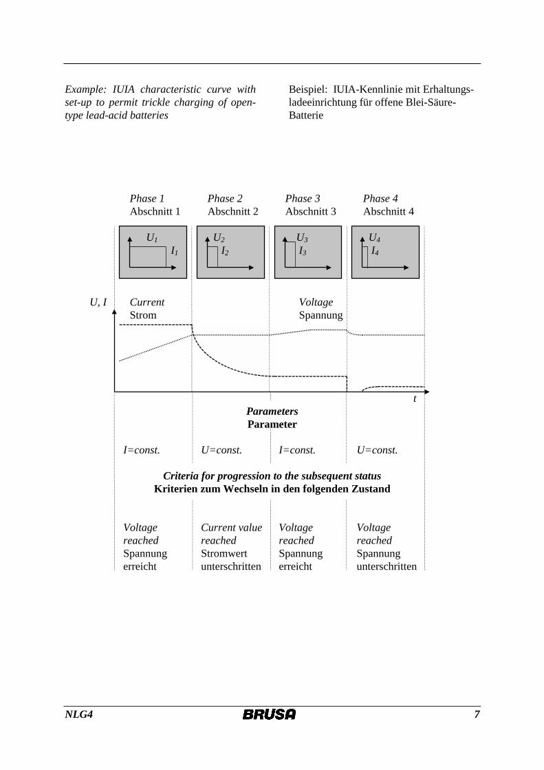
Example: IUIA characteristic curve with set-up to permit trickle charging of open-type lead-acid batteries
Beispiel: IUIA-Kennlinie mit Erhaltungs-ladeeinrichtung für offene Blei-Säure-Batterie
Phase 1 Phase 2 Phase 3 Phase 4 Abschnitt 1 Abschnitt 2 Abschnitt 3 Abschnitt 4 U1 U2 U3 U4 I1 I2 I3 I4 U, I Current Voltage Strom Spannung t
Parameters Parameter
I=const. U=const. I=const. U=const.
Criteria for progression to the subsequent status Kriterien zum Wechseln in den folgenden Zustand
Voltage Current value Voltage Voltage reached reached reached reached Spannung Stromwert Spannung Spannung erreicht unterschritten erreicht unterschritten
NLG4 8
5. Connections and wiring
5.1 Minimum wiring requirements
In principle, the charger can be operated without external controls connected. For a minimum configuration, the charger as supplied requires to be connected to the mains supply and to the battery, with pins 11, 12 and 18 wired as described in sec-tion 6.6, and pins 9 and 10 connected in accordance with the instructions at section 6.7.
When operated in this way, charging be-gins at full output in accordance with pre-set characteristics as soon as it is con-nected to the mains supply.
Connection to the mains supply: 3-core, double-insulated supply cord with 3 x 2.5 mm2 cross section Conductor ends should be fitted with end sleeves in order to comply with regula-tions. It is also necessary to clarify whether local conditions will permit the charger to be operated at full output. (Please refer to section "Additional func-tions" for information on reducing output.)
Connection to the battery: 2 single conductors with a cross section of at least 4 mm2
In order to comply with applicable regula-tions, it may be necessary to use a double-insulated battery cable or to install the ca-ble in an enclosing and insulating conduit or sleeve.
5. Anschlüsse
5.1 Minimalverdrahtung
Prinzipiell sind für die Inbetriebnahme keine externen Bedienelemente notwendig. Im Anlieferungszustand umfasst der mini-male Verdrahtungsaufwand einen Netz- und einen Batterieanschluss, sowie die Verdrahtung von Pin 11, 12 und 18 gemäss Kapitel 6.6 und Pin 9 und Pin 10 gemäss Kapitel 6.7.
In dieser Betriebsart beginnt nach dem Einstecken der Ladevorgang nach der ein-gestellten Ladekennlinie mit der vollen Ladeleistung.
Netzanschluss:
3-adriges, zweifach isoliertes Netzkabel mit 3 x 2,5 mm2 Querschnitt. Für einen vorschriftsmässigen Anschluss sind die Enden mit Aderendhülsen zu ver-sehen. Zudem ist abzuklären, ob die loka-len Gegebenheiten ein Laden mit voller Leistung zulassen. (Reduzieren der Lade-leistung siehe Zusatzfunktionen).
Batterieanschluss:
2 Einzellitzen mit mind. 4 mm2 Quer-schnitt. Entsprechend den geltenden Vorschriften kann es erforderlich sein, doppelt isolierte Batteriekabel einzusetzen oder diese in ei-nem geschlossenen und isolierenden Rohr zu verlegen.
NLG4 9
PC-Schnittstelle
Benutzerstecker
Batteriekabel -
Batteriekabel +
Lüfterkabel
Netzstecker
PC-Schnittstelle
Benutzerstecker
Batteriekabel -
Batteriekabel +
Lüfterkabel
Netzstecker
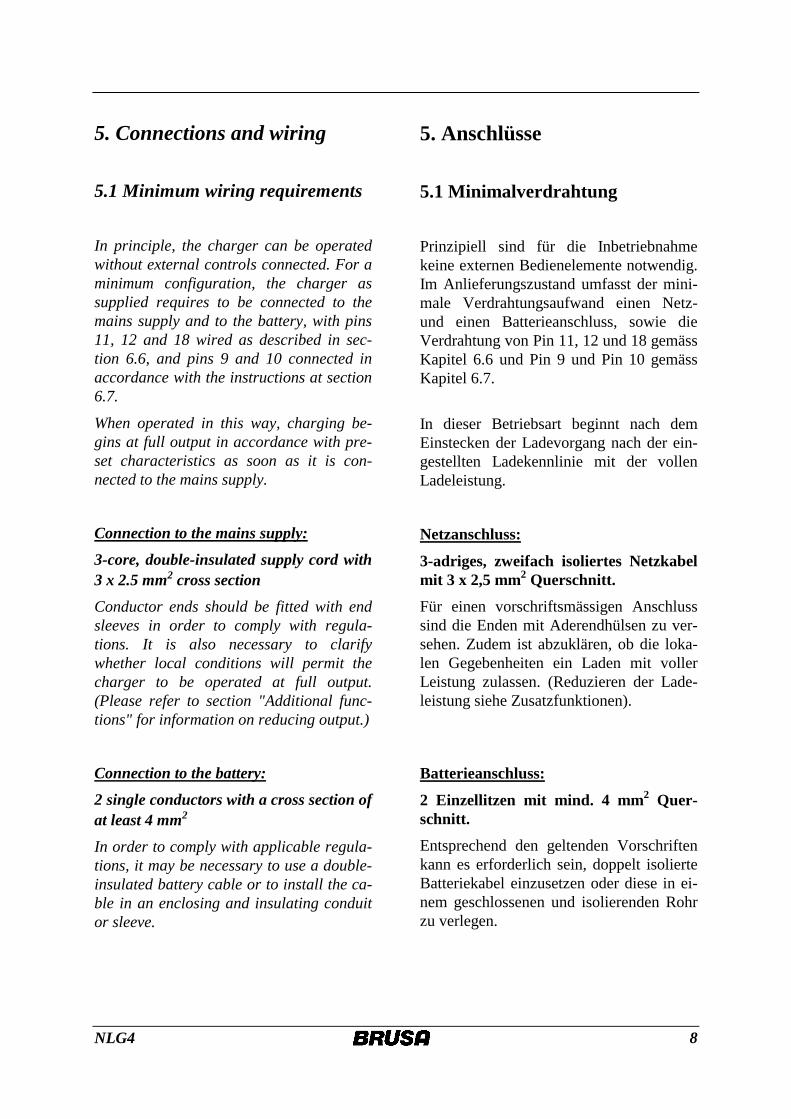
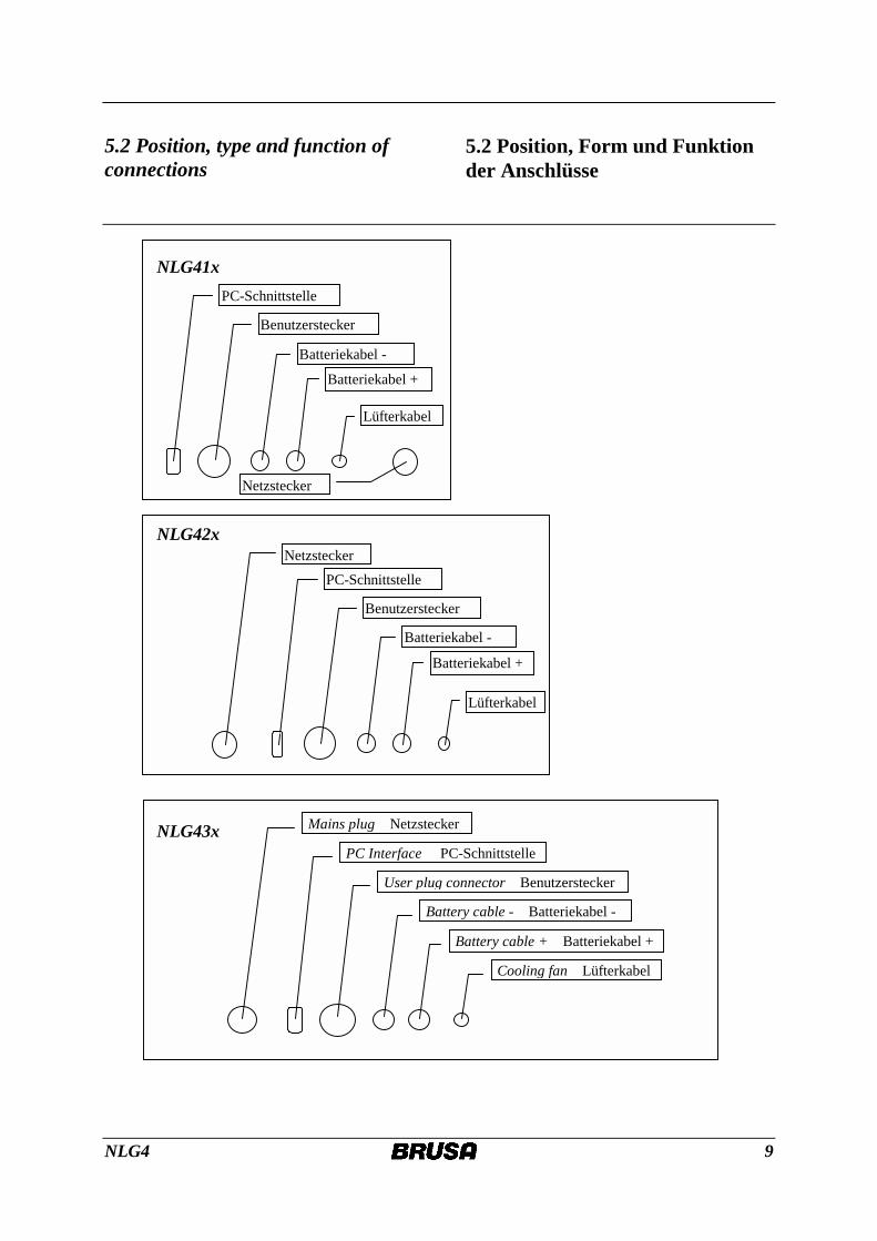
PC Interface PC-Schnittstelle
User plug connector Benutzerstecker
Battery cable - Batteriekabel -
Battery cable + Batteriekabel +
Cooling fan Lüfterkabel
Mains plug Netzstecker
5.2 Position, type and function of connections
5.2 Position, Form und Funktion der Anschlüsse
NLG41x
NLG42x
NLG43x
NLG4 10
6. Additional functions
6.1 Adjusting the maximum cur-rent input
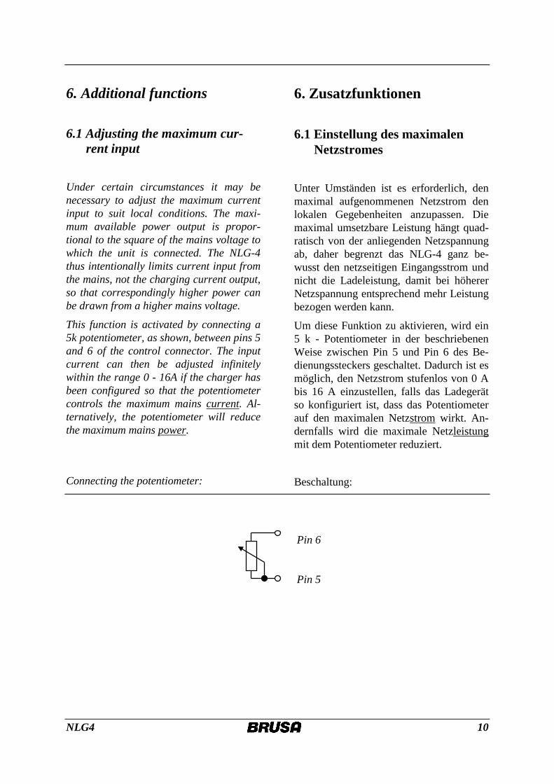
Under certain circumstances it may be necessary to adjust the maximum current input to suit local conditions. The maxi-mum available power output is propor-tional to the square of the mains voltage to which the unit is connected. The NLG-4 thus intentionally limits current input from the mains, not the charging current output, so that correspondingly higher power can be drawn from a higher mains voltage.
This function is activated by connecting a 5k potentiometer, as shown, between pins 5 and 6 of the control connector. The input current can then be adjusted infinitely within the range 0 - 16A if the charger has been configured so that the potentiometer controls the maximum mains current. Al-ternatively, the potentiometer will reduce the maximum mains power.
Connecting the potentiometer:
6. Zusatzfunktionen
6.1 Einstellung des maximalen Netzstromes
Unter Umständen ist es erforderlich, den maximal aufgenommenen Netzstrom den lokalen Gegebenheiten anzupassen. Die maximal umsetzbare Leistung hängt quad-ratisch von der anliegenden Netzspannung ab, daher begrenzt das NLG-4 ganz be-wusst den netzseitigen Eingangsstrom und nicht die Ladeleistung, damit bei höherer Netzspannung entsprechend mehr Leistung bezogen werden kann.
Um diese Funktion zu aktivieren, wird ein 5 k - Potentiometer in der beschriebenen Weise zwischen Pin 5 und Pin 6 des Be-dienungssteckers geschaltet. Dadurch ist es möglich, den Netzstrom stufenlos von 0 A bis 16 A einzustellen, falls das Ladegerät so konfiguriert ist, dass das Potentiometer auf den maximalen Netzstrom wirkt. An-dernfalls wird die maximale Netzleistung mit dem Potentiometer reduziert.
Beschaltung:
Pin 6 Pin 5
NLG4 11
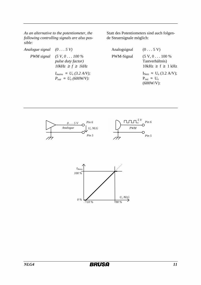
As an alternative to the potentiometer, the following controlling signals are also pos-sible:
Analogue signal (0 . . . 5 V)
PWM signal (5 V, 0 . . . 100 % pulse duty factor) 10kHz ≥ f ≥ 1kHz
Imains ≈ Ue (3.2 A/V); Pout ≈ Ue (600W/V):
Statt des Potentiometers sind auch folgen-de Steuersignale möglich:
Analogsignal (0 . . . 5 V)
PWM-Signal (5 V, 0 . . . 100 % Tastverhältnis) 10kHz ≥ f ≥ 1 kHz
INetz ≈ Ue (3.2 A/V); Pout ≈ Ue (600W/V):
Ue NLG
IMains
90 % 10 % 0 %
100 %
Pin 6 Pin 6 0 . . . 5 V 5 V
PWM Analogue Ue NLG
Pin 5 Pin 5
NLG4 12
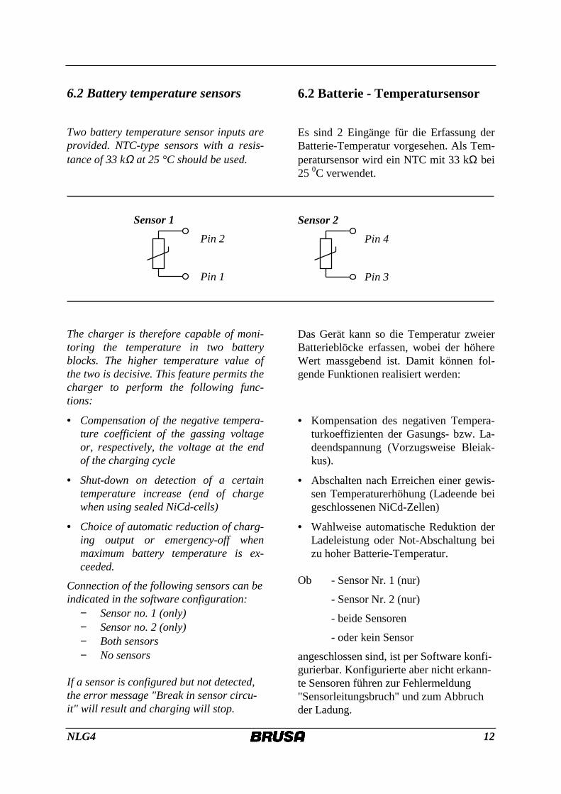
6.2 Battery temperature sensors
Two battery temperature sensor inputs are provided. NTC-type sensors with a resis-tance of 33 kΩ at 25 °C should be used.
Sensor 1 Pin 2
Pin 1
The charger is therefore capable of moni-toring the temperature in two battery blocks. The higher temperature value of the two is decisive. This feature permits the charger to perform the following func-tions:
• Compensation of the negative tempera-ture coefficient of the gassing voltage or, respectively, the voltage at the end of the charging cycle
• Shut-down on detection of a certain temperature increase (end of charge when using sealed NiCd-cells)
• Choice of automatic reduction of charg-ing output or emergency-off when maximum battery temperature is ex-ceeded.
Connection of the following sensors can be indicated in the software configuration:
− Sensor no. 1 (only) − Sensor no. 2 (only) − Both sensors − No sensors
If a sensor is configured but not detected, the error message "Break in sensor circu-it" will result and charging will stop.
6.2 Batterie - Temperatursensor
Es sind 2 Eingänge für die Erfassung der Batterie-Temperatur vorgesehen. Als Tem-peratursensor wird ein NTC mit 33 kΩ bei 25 0C verwendet.
Sensor 2 Pin 4
Pin 3
Das Gerät kann so die Temperatur zweier Batterieblöcke erfassen, wobei der höhere Wert massgebend ist. Damit können fol-gende Funktionen realisiert werden:
• Kompensation des negativen Tempera-turkoeffizienten der Gasungs- bzw. La-deendspannung (Vorzugsweise Bleiak-kus).
• Abschalten nach Erreichen einer gewis-sen Temperaturerhöhung (Ladeende bei geschlossenen NiCd-Zellen)
• Wahlweise automatische Reduktion der Ladeleistung oder Not-Abschaltung bei zu hoher Batterie-Temperatur.
Ob - Sensor Nr. 1 (nur)
- Sensor Nr. 2 (nur)
- beide Sensoren
- oder kein Sensor
angeschlossen sind, ist per Software konfi-gurierbar. Konfigurierte aber nicht erkann-te Sensoren führen zur Fehlermeldung "Sensorleitungsbruch" und zum Abbruch der Ladung.
NLG4 13
6.3 Universal control inputs As a further possibility for influence the charger there are two digital inputs at the control plug. These functions can be de-fined by software. (See the software de-scription)
6.3 Universelle Eingänge
Als weitere Möglichkeit zur Beeinflussung des Ladegerätes stehen am Bedienungsste-cker zwei digitale Eingänge zur Verfügung. Deren Funktion kann softwaremässig defi-niert werden. (Siehe Beschreibung der Software)
One possibility, for example, would be the use of an external battery management sys-tem to monitor the charging procedure.
Denkbar wäre zum Beispiel eine Überwa-chung der Ladung mittels externem Batte-riemanagementsystem.
The inputs pin 7 and pin 8 from the control plug can be controlled with a nominal logi-cal signal from 5 to 15 V against pin 18 (ground). (max. -13V...+40V)
Die Eingänge an Pin 7 und 8 des Bedie-nungssteckers können mit nominal 5 - 15 V (max. -13V - +40V) Logiksignalen be-züglich Pin 18 (Ground) angesteuert wer-den.
6.4 Status indicator
The charger is also equipped with an out-put which provides information on its im-mediate operating status. If the signal at this connection indicates a logical "1", the battery will not be charged despite the unit being connected to the mains supply - the charger switches to the "Battery charge not possible" status.
6.4 Statusanzeige
Zusätzlich steht auch ein Ausgang für die Information über den momentanen Be-triebszustand zur Verfügung. Tritt an die-sem Ausgang eine logische 1 auf, wird die Batterie trotz anliegender Netzspannung nicht geladen, das Gerät wechselt in den Zustand „Batterieladung nicht möglich“.
NLG4 14
Software-controlled criteria which acti-vate the status "Battery charge not possi-ble" • Characteristic parameters changed un-
intentionally (LED blinks)
• Activation of a safety cut-out criterion (The values underlined below are only examples, other values can be pro-grammed.): 1) Battery temperature over 60°C 2) Output voltage over 250V (possibly
not connected / wrongly connected) 3) Total energy charged over 30kWh 4) Total charge over 150 Ah 5) Total elapsed charging time over 16
hours
6) Internal fault detected by self-test
Software Auslösekriterien des Zustands „Batterieladung nicht möglich“ • Unbeabsichtigte Veränderung an den
Kennlinienparametern (LED blinkt) • Auslösen eines Sicherheitsabschaltkrite-
riums (Die unterstrichenen Zahlenwerte sind Beispiele, andere Werte sind pro-grammierbar):
1) Batterietemperatur über 60 °C 2) Ausgangsspannung über 250 V (mög-
licherweise Batteriestromkreis unter-brochen)
3) eingeladene Gesamtenergiemenge über 30 kWh
4) eingeladene Gesamtladungsmenge über 150 Ah
5) verstrichene Gesamtladezeit mehr als 16 h
6) Selbstdiagnose stellt einen internen Fehler fest
Hardware-controlled criteria which acti-vate the status "Battery charge not possi-ble" • Activation of external safety cut-out cri-
terion (highest priority) • No load at charger output (e.g. not con-
nected to battery) This status information is provided at pin 13 of the control connector. This pin sup-plies a voltage (with no load) of 10V rela-tive to vehicle ground, has an internal re-sistance of approx. 100 Ω, and is limited to a current of approx. 30 mA. We recom-mend the use of an LED indicator with an appropriate series resistor.
Hardware Auslösekriterien des Zustan-des „Batterieladung nicht möglich“ • Auslösen des externen Sicherheitsab-
schaltekriteriums (höchste Priorität) • Betrieb des Ladegerätes mit leerlaufen-
dem Ausgang = Batterieüberspannung Die Statusinformation steht an Pin 13 des Bedienungssteckers zur Verfügung. Die-ser Ausgang liefert unbelastet 10V gegen-über Fahrzeugmasse, hat etwa 100 Ω In-nenwiderstand und ist strombegrenzt bei ca. 30 mA. Als Anzeige empfehlen wir Leuchtdioden mit einem entsprechenden Vorwiderstand.

NLG4 15
6.5 Indication of charging status
It is useful in many instances when infor-mation on the progress of the charging procedure can be obtained at a glance. Four outputs, which can be configured as desired, are provided for the purpose of connecting an indicator system.
Pins 14 to 17 of the control connector sup-ply the charging status information. In the standard configuration, each phase of the characteristic curve is indicated by its own output:
Phase Output no. Pin no. Phase 1 Output 1 14
Phase 2 Output 2 15
Phase 3 Output 3 16
Phase 4 Output 4 17
GND 18
These outputs have an internal resistance of approx. 100 Ω and each can supply a voltage (with no load) of 10 V relative to vehicle ground (pin 18) and a current of up to 30 mA. We recommend the use of LED indicators with appropriate series resis-tors.
6.5 Ladezustandsanzeige
In vielen Fällen ist es nützlich, wenn man sich auf einfache Weise über den Fortgang des Ladevorganges informieren kann. Zu diesem Zweck sind 4 in beliebiger Weise konfigurierbare Ausgänge vorgesehen, an denen Meldeeinrichtungen angeschlossen werden können.
Die Information über den Ladezustand ist an den Pins 14 bis 17 des Bedienungsste-ckers verfügbar. In der Standardkonfigura-tion wird jeder Abschnitt der Ladekennli-nie durch einen eigenen Ausgang ange-zeigt:
Abschnitt Ausgangs-Nr. Pin-Nr Abschnitt 1 Ausgang 1 14
Abschnitt 2 Ausgang 2 15
Abschnitt 3 Ausgang 3 16
Abschnitt 4 Ausgang 4 17
GND 18
Jeder dieser Ausgänge liefert unbelastet 10 V gegenüber Fahrzeugmasse (Pin 18), hat etwa 100 Ω Innenwiderstand und ist Strombegrenzt bei ca. 30 mA. Als Anzeige empfehlen wir Leuchtdioden mit einem entsprechenden Vorwiderstand.
NLG4 16
6.6 Main switch
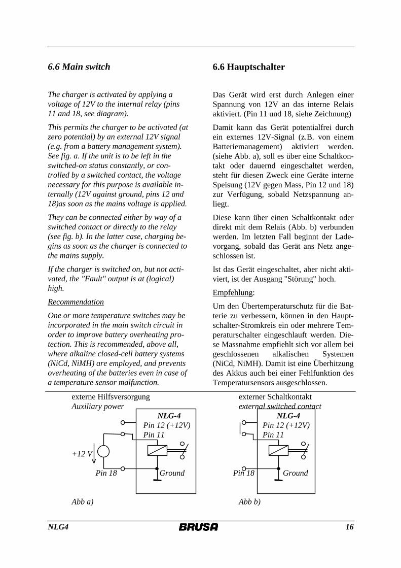
The charger is activated by applying a voltage of 12V to the internal relay (pins 11 and 18, see diagram).
This permits the charger to be activated (at zero potential) by an external 12V signal (e.g. from a battery management system). See fig. a. If the unit is to be left in the switched-on status constantly, or con-trolled by a switched contact, the voltage necessary for this purpose is available in-ternally (12V against ground, pins 12 and 18)as soon as the mains voltage is applied.
They can be connected either by way of a switched contact or directly to the relay (see fig. b). In the latter case, charging be-gins as soon as the charger is connected to the mains supply.
If the charger is switched on, but not acti-vated, the "Fault" output is at (logical) high.
Recommendation
One or more temperature switches may be incorporated in the main switch circuit in order to improve battery overheating pro-tection. This is recommended, above all, where alkaline closed-cell battery systems (NiCd, NiMH) are employed, and prevents overheating of the batteries even in case of a temperature sensor malfunction.
6.6 Hauptschalter
Das Gerät wird erst durch Anlegen einer Spannung von 12V an das interne Relais aktiviert. (Pin 11 und 18, siehe Zeichnung)
Damit kann das Gerät potentialfrei durch ein externes 12V-Signal (z.B. von einem Batteriemanagement) aktiviert werden. (siehe Abb. a), soll es über eine Schaltkon-takt oder dauernd eingeschaltet werden, steht für diesen Zweck eine Geräte interne Speisung (12V gegen Mass, Pin 12 und 18) zur Verfügung, sobald Netzspannung an-liegt.
Diese kann über einen Schaltkontakt oder direkt mit dem Relais (Abb. b) verbunden werden. Im letzten Fall beginnt der Lade-vorgang, sobald das Gerät ans Netz ange-schlossen ist.
Ist das Gerät eingeschaltet, aber nicht akti-viert, ist der Ausgang "Störung" hoch.
Empfehlung:
Um den Übertemperaturschutz für die Bat-terie zu verbessern, können in den Haupt-schalter-Stromkreis ein oder mehrere Tem-peraturschalter eingeschlauft werden. Die-se Massnahme empfiehlt sich vor allem bei geschlossenen alkalischen Systemen (NiCd, NiMH). Damit ist eine Überhitzung des Akkus auch bei einer Fehlfunktion des Temperatursensors ausgeschlossen.
externe Hilfsversorgung externer Schaltkontakt Auxiliary power external switched contact NLG-4 NLG-4 Pin 12 (+12V) Pin 12 (+12V) Pin 11 Pin 11 +12 V Pin 18 Ground Pin 18 Ground Abb a) Abb b)
NLG4 17
6.7 "Drive" switch input
For optimum battery care the charging procedure must give consideration to the phases of the charging sequence already completed before advancing to the next phase. If the charging procedure is inter-rupted for some reason , e.g. a power fail-ure or unintentional disconnection of the supply cord, charging should then be re-sumed at the phase of the characteristic curve at which the interruption occurred. On the other hand, if the battery is dis-charged during this interruption, the charging procedure should then be re-started at the beginning, even if the dis-charge is only slight.
In order to permit the NLG-4 to differenti-ate between these two situations, it is nec-essary to provide a 12 V signal indicating "Drive" to the control connector. The volt-age of this signal may be different to that of the vehicle's auxiliary power circuit but must be connected with correct polarity and must not be inverted:
"Drive" signal, positive terminal pin 9
"Drive" signal, negative terminal pin 10
Please note: The insulating gap between the pins in the control connector is mini-mal. For this reason, the maximum permit-ted voltage is 100 V.
If this function is not required, i.e. the charging cycle should always start at the beginning of the characteristic curve after an interruption in the mains supply, pin 9 should be permanently connected to pin 12 (12V internal) and pin 10 should be con-nected to pin 18 (ground).
6.7 Fahrschalter-Eingang
Zur optimalen Batteriepflege ist es sinn-voll, die Vorgeschichte eines Ladezyklus zu kennen und im Ladevorgang zu berück-sichtigen. Wird ein einmal begonnener La-devorgang durch irgendwelche Umstände unterbrochen z.B. durch einen Netzausfall oder durch unbeabsichtigtes Ausstecken, sollte die Ladung in dem Abschnitt der Kennlinie fortgesetzt werden, in dem die Unterbrechung aufgetreten ist. Entlädt man die Batterie während der Unterbrechung, rechtfertigt dies den Ladevorgang neu zu starten, auch wenn nur eine kleine La-dungsmenge entnommen worden ist.
Damit das NLG-4 zwischen diesen Fällen unterscheiden kann, ist es notwendig ein 12 V Signal, das den Zustand „Fahren“ in-diziert, an den Bedienungsstecker heranzu-führen. Dieses Signal darf auch auf einem anderen Potential als dem Bordnetz liegen, muss aber mit richtiger Polarität angeschlossen und nichtinvertiert vorliegen:
Signal „Fahren“ plus Pin 9
Signal „Fahren“ minus Pin 10
Beachten Sie aber bitte, dass aufgrund der geringen Abstände der Pins am Bedien-schalter keine grösseren Isolierspannungen als 100 V zugelassen werden können.
Ist diese Funktion nicht erwünscht, d.h. die Kennlinie soll nach einem Netzunterbruch immer von Angang an durchlaufen werden, ist Pin 9 mit Pin 12 (12V intern) und Pin 10 mit Pin 18 (GND) dauerhaft zu verbin-den.
NLG4 18
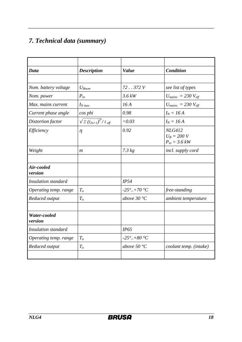
7. Technical data (summary)
Data Description Value Condition
Nom. battery voltage UBnom 72 . . 372 V see list of types
Nom. power Pin 3.6 kW Umains = 230 Veff
Max. mains current IN max 16 A Umains = 230 Veff
Current phase angle cos phi 0.98 IN = 16 A
Distortion factor √ Σ (i2n+1)2 / i eff <0.03 IN = 16 A
Efficiency η 0.92 NLG412 UB = 200 V Pin = 3.6 kW
Weight m 7.3 kg incl. supply cord
Air-cooled version
Insulation standard IP54
Operating temp. range Ta -25°..+70 °C free-standing
Reduced output Ta above 30 °C ambient temperature
Water-cooled version
Insulation standard IP65
Operating temp. range Ta -25°..+80 °C
Reduced output Ta above 50 °C coolant temp. (intake)
NLG4 19
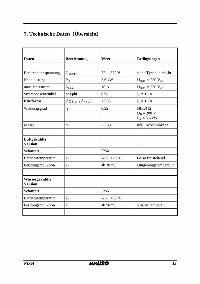
7. Technische Daten (Übersicht)
Daten Bezeichnung Wert Bedingungen
Batterienennspannung UBnenn 72 . . 372 V siehe Typenübersicht
Nennleistung Pin 3,6 kW UNetz = 230 Veff
max. Netzstrom IN max 16 A UNetz = 230 Veff
Stromphasenwinkel cos phi 0.98 IN = 16 A
Klirrfaktor √ Σ (i2n+1)2 / i eff <0.03 IN = 16 A
Wirkungsgrad η 0,92 NLG412 UB = 200 V Pin = 3.6 kW
Masse m 7,3 kg inkl. Anschlußkabel
Luftgekühlte Version
Schutzart IP54
Betriebstemperatur Ta -25°..+70 °C Gerät freistehend
Leistungsreduktion Ta ab 30 °C Umgebungstemperatur
Wassergekühlte Version
Schutzart IP65
Betriebstemperatur Ta -25°..+80 °C
Leistungsreduktion Ta ab 50 °C Vorlauftemperatur
NLG4 20
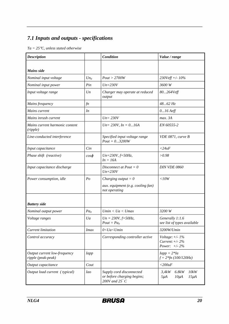
7.1 Inputs and outputs - specifications
Ta = 25°C, unless stated otherwise
Description Condition Value / range
Mains side
Nominal input voltage Un0 Pout > 2700W 230Veff +/- 10%
Nominal input power Pin Un=230V 3600 W
Input voltage range Un Charger may operate at reduced output
80...264Veff
Mains frequency fn 48...62 Hz
Mains current In 0...16 Aeff
Mains inrush current Un= 230V max. 3A
Mains current harmonic content (ripple)
Un= 230V, In = 0...16A EN 60555-2
Line-conducted interference Specified input voltage range Pout = 0...3200W
VDE 0871, curve B
Input capacitance Cin <24uF
Phase shift (reactive) cosϕ Un=230V, f=50Hz, In = 16A
>0.98
Input capacitance discharge Disconnect at Pout = 0 Un=230V
DIN VDE 0860
Power consumption, idle Po Charging output = 0
aux. equipment (e.g. cooling fan) not operating
<10W
Battery side
Nominal output power Pa0 Umin < Ua < Umax 3200 W
Voltage ranges Ua Un = 230V, f=50Hz, Pout = Pa0
Generally 1:1.6 see list of types available
Current limitation Imax 0<Ua<Umin 3200W/Umin
Control accuracy Corresponding controller active Voltage: +/- 1% Current: +/- 2% Power: +/- 2%
Output current low-frequency ripple (peak-peak)
Iapp Iapp = 2*Ia f = 2*fn (100/120Hz)
Output capacitance Cout <200uF
Output load current ( typical) Iao Supply cord disconnected or before charging begins; 200V and 25° C
3,4kW 6.8kW 10kW 5µA 10µA 15µA
NLG4 21
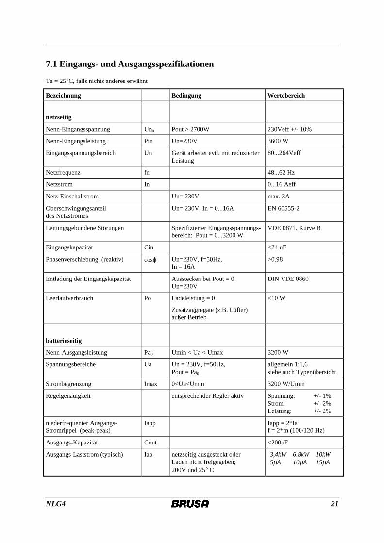
7.1 Eingangs- und Ausgangsspezifikationen
Ta = 25°C, falls nichts anderes erwähnt
Bezeichnung Bedingung Wertebereich
netzseitig
Nenn-Eingangsspannung Un0 Pout > 2700W 230Veff +/- 10%
Nenn-Eingangsleistung Pin Un=230V 3600 W
Eingangsspannungsbereich Un Gerät arbeitet evtl. mit reduzierter Leistung
80...264Veff
Netzfrequenz fn 48...62 Hz
Netzstrom In 0...16 Aeff
Netz-Einschaltstrom Un= 230V max. 3A
Oberschwingungsanteil des Netzstromes
Un= 230V, In = 0...16A EN 60555-2
Leitungsgebundene Störungen Spezifizierter Eingangsspannungs-bereich: Pout = 0...3200 W
VDE 0871, Kurve B
Eingangskapazität Cin <24 uF
Phasenverschiebung (reaktiv) cosϕ Un=230V, f=50Hz, In = 16A
>0.98
Entladung der Eingangskapazität Ausstecken bei Pout = 0 Un=230V
DIN VDE 0860
Leerlaufverbrauch Po Ladeleistung = 0
Zusatzaggregate (z.B. Lüfter) außer Betrieb
<10 W
batterieseitig
Nenn-Ausgangsleistung Pa0 Umin < Ua < Umax 3200 W
Spannungsbereiche Ua Un = 230V, f=50Hz, Pout = Pa0
allgemein 1:1,6 siehe auch Typenübersicht
Strombegrenzung Imax 0<Ua<Umin 3200 W/Umin
Regelgenauigkeit entsprechender Regler aktiv Spannung: +/- 1% Strom: +/- 2% Leistung: +/- 2%
niederfrequenter Ausgangs-Stromrippel (peak-peak)
Iapp Iapp = 2*Ia f = 2*fn (100/120 Hz)
Ausgangs-Kapazität Cout <200uF
Ausgangs-Laststrom (typisch) Iao netzseitig ausgesteckt oder Laden nicht freigegeben; 200V und 25° C
3,4kW 6.8kW 10kW 5µA 10µA 15µA
NLG4 22
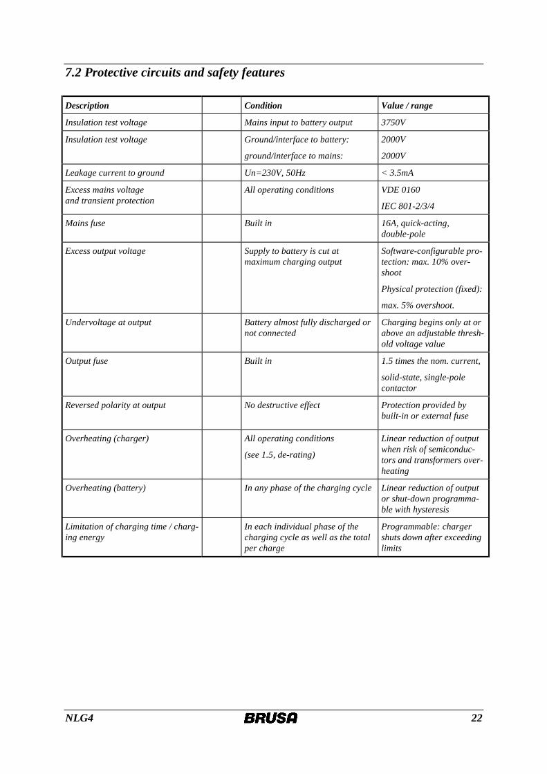
7.2 Protective circuits and safety features Description Condition Value / range
Insulation test voltage Mains input to battery output 3750V
Insulation test voltage Ground/interface to battery:
ground/interface to mains:
2000V
2000V
Leakage current to ground Un=230V, 50Hz < 3.5mA
Excess mains voltage and transient protection
All operating conditions VDE 0160
IEC 801-2/3/4
Mains fuse Built in 16A, quick-acting, double-pole
Excess output voltage Supply to battery is cut at maximum charging output
Software-configurable pro-tection: max. 10% over-shoot
Physical protection (fixed):
max. 5% overshoot.
Undervoltage at output Battery almost fully discharged or not connected
Charging begins only at or above an adjustable thresh-old voltage value
Output fuse Built in 1.5 times the nom. current,
solid-state, single-pole contactor
Reversed polarity at output No destructive effect
Protection provided by built-in or external fuse
Overheating (charger) All operating conditions
(see 1.5, de-rating)
Linear reduction of output when risk of semiconduc-tors and transformers over-heating
Overheating (battery) In any phase of the charging cycle Linear reduction of output or shut-down programma-ble with hysteresis
Limitation of charging time / charg-ing energy
In each individual phase of the charging cycle as well as the total per charge
Programmable: charger shuts down after exceeding limits
NLG4 23
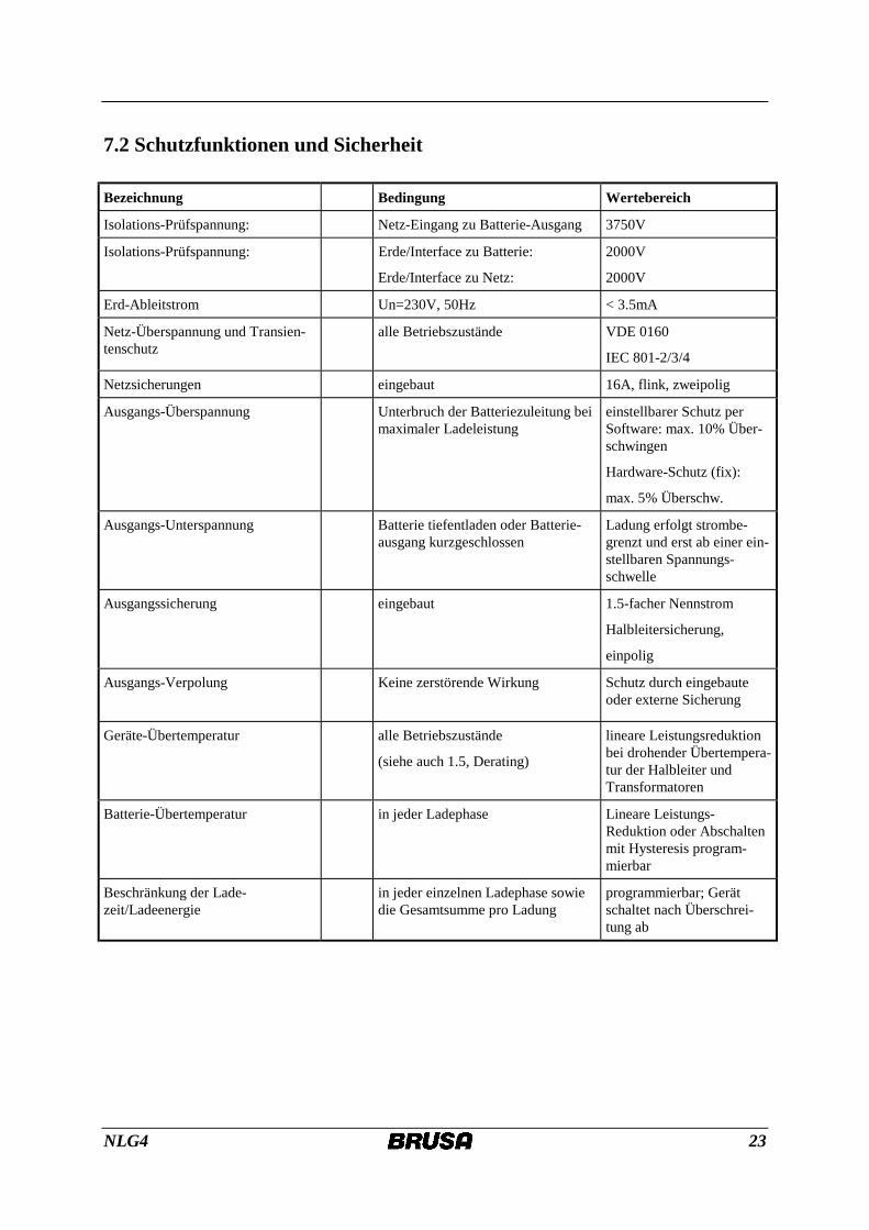
7.2 Schutzfunktionen und Sicherheit
Bezeichnung Bedingung Wertebereich
Isolations-Prüfspannung: Netz-Eingang zu Batterie-Ausgang 3750V
Isolations-Prüfspannung: Erde/Interface zu Batterie:
Erde/Interface zu Netz:
2000V
2000V
Erd-Ableitstrom Un=230V, 50Hz < 3.5mA
Netz-Überspannung und Transien-tenschutz
alle Betriebszustände VDE 0160
IEC 801-2/3/4
Netzsicherungen eingebaut 16A, flink, zweipolig
Ausgangs-Überspannung Unterbruch der Batteriezuleitung bei maximaler Ladeleistung
einstellbarer Schutz per Software: max. 10% Über-schwingen
Hardware-Schutz (fix):
max. 5% Überschw.
Ausgangs-Unterspannung Batterie tiefentladen oder Batterie-ausgang kurzgeschlossen
Ladung erfolgt strombe-grenzt und erst ab einer ein-stellbaren Spannungs-schwelle
Ausgangssicherung eingebaut 1.5-facher Nennstrom
Halbleitersicherung,
einpolig
Ausgangs-Verpolung Keine zerstörende Wirkung
Schutz durch eingebaute oder externe Sicherung
Geräte-Übertemperatur alle Betriebszustände
(siehe auch 1.5, Derating)
lineare Leistungsreduktion bei drohender Übertempera-tur der Halbleiter und Transformatoren
Batterie-Übertemperatur in jeder Ladephase Lineare Leistungs-Reduktion oder Abschalten mit Hysteresis program-mierbar
Beschränkung der Lade-zeit/Ladeenergie
in jeder einzelnen Ladephase sowie die Gesamtsumme pro Ladung
programmierbar; Gerät schaltet nach Überschrei-tung ab
NLG4 24
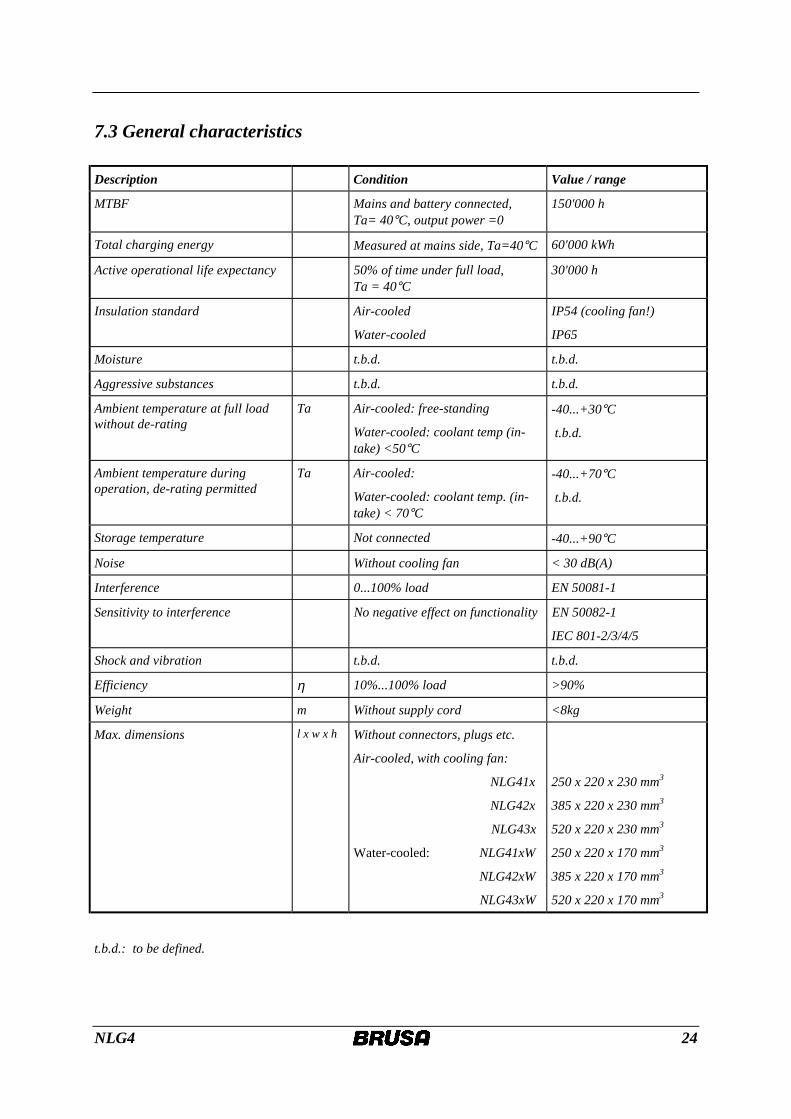
7.3 General characteristics Description Condition Value / range
MTBF Mains and battery connected, Ta= 40°C, output power =0
150'000 h
Total charging energy Measured at mains side, Ta=40°C 60'000 kWh
Active operational life expectancy 50% of time under full load, Ta = 40°C
30'000 h
Insulation standard Air-cooled
Water-cooled
IP54 (cooling fan!)
IP65
Moisture t.b.d. t.b.d.
Aggressive substances t.b.d. t.b.d.
Ambient temperature at full load without de-rating
Ta Air-cooled: free-standing
Water-cooled: coolant temp (in-take) <50°C
-40...+30°C
t.b.d.
Ambient temperature during operation, de-rating permitted
Ta Air-cooled:
Water-cooled: coolant temp. (in-take) < 70°C
-40...+70°C
t.b.d.
Storage temperature Not connected -40...+90°C
Noise Without cooling fan < 30 dB(A)
Interference 0...100% load EN 50081-1
Sensitivity to interference No negative effect on functionality EN 50082-1
IEC 801-2/3/4/5
Shock and vibration t.b.d. t.b.d.
Efficiency η 10%...100% load >90%
Weight m Without supply cord <8kg
Max. dimensions l x w x h Without connectors, plugs etc.
Air-cooled, with cooling fan:
NLG41x
NLG42x
NLG43x
Water-cooled: NLG41xW
NLG42xW
NLG43xW
250 x 220 x 230 mm3
385 x 220 x 230 mm3
520 x 220 x 230 mm3
250 x 220 x 170 mm3
385 x 220 x 170 mm3
520 x 220 x 170 mm3
t.b.d.: to be defined.
NLG4 25
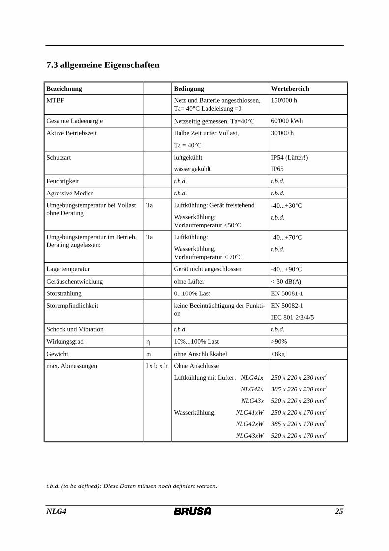
7.3 allgemeine Eigenschaften
Bezeichnung Bedingung Wertebereich
MTBF Netz und Batterie angeschlossen, Ta= 40°C Ladeleisung =0
150'000 h
Gesamte Ladeenergie Netzseitig gemessen, Ta=40°C 60'000 kWh
Aktive Betriebszeit Halbe Zeit unter Vollast,
Ta = 40°C
30'000 h
Schutzart luftgekühlt
wassergekühlt
IP54 (Lüfter!)
IP65
Feuchtigkeit t.b.d. t.b.d.
Agressive Medien t.b.d. t.b.d.
Umgebungstemperatur bei Vollast ohne Derating
Ta Luftkühlung: Gerät freistehend
Wasserkühlung: Vorlauftemperatur <50°C
-40...+30°C
t.b.d.
Umgebungstemperatur im Betrieb, Derating zugelassen:
Ta Luftkühlung:
Wasserkühlung, Vorlauftemperatur < 70°C
-40...+70°C
t.b.d.
Lagertemperatur Gerät nicht angeschlossen -40...+90°C
Geräuschentwicklung ohne Lüfter < 30 dB(A)
Störstrahlung 0...100% Last EN 50081-1
Störempfindlichkeit keine Beeinträchtigung der Funkti-on
EN 50082-1
IEC 801-2/3/4/5
Schock und Vibration t.b.d. t.b.d.
Wirkungsgrad η 10%...100% Last >90%
Gewicht m ohne Anschlußkabel <8kg
max. Abmessungen l x b x h Ohne Anschlüsse
Luftkühlung mit Lüfter: NLG41x
NLG42x
NLG43x
Wasserkühlung: NLG41xW
NLG42xW
NLG43xW
250 x 220 x 230 mm3
385 x 220 x 230 mm3
520 x 220 x 230 mm3
250 x 220 x 170 mm3
385 x 220 x 170 mm3
520 x 220 x 170 mm3
t.b.d. (to be defined): Diese Daten müssen noch definiert werden.
NLG4 26
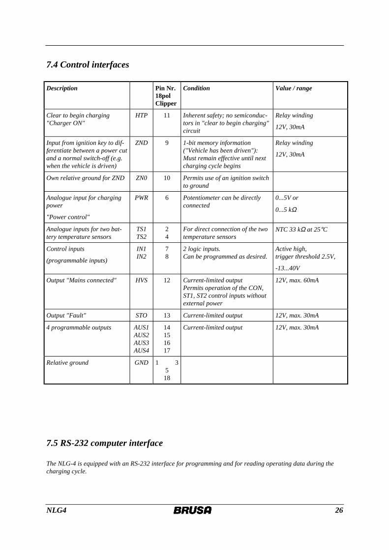
7.4 Control interfaces Description Pin Nr.
18pol Clipper
Condition Value / range
Clear to begin charging "Charger ON"
HTP 11 Inherent safety; no semiconduc-tors in "clear to begin charging" circuit
Relay winding
12V, 30mA
Input from ignition key to dif-ferentiate between a power cut and a normal switch-off (e.g. when the vehicle is driven)
ZND 9 1-bit memory information ("Vehicle has been driven"): Must remain effective until next charging cycle begins
Relay winding
12V, 30mA
Own relative ground for ZND ZN0 10 Permits use of an ignition switch to ground
Analogue input for charging power
"Power control"
PWR 6 Potentiometer can be directly connected
0...5V or
0...5 kΩ
Analogue inputs for two bat-tery temperature sensors
TS1 TS2
2 4
For direct connection of the two temperature sensors
NTC 33 kΩ at 25°C
Control inputs
(programmable inputs)
IN1 IN2
7 8
2 logic inputs. Can be programmed as desired.
Active high, trigger threshold 2.5V,
-13...40V
Output "Mains connected" HVS 12 Current-limited output Permits operation of the CON, ST1, ST2 control inputs without external power
12V, max. 60mA
Output "Fault" STO 13 Current-limited output 12V, max. 30mA
4 programmable outputs
AUS1 AUS2 AUS3 AUS4
14 15 16 17
Current-limited output 12V, max. 30mA
Relative ground GND 1 3 5
18
7.5 RS-232 computer interface The NLG-4 is equipped with an RS-232 interface for programming and for reading operating data during the charging cycle.
NLG4 27
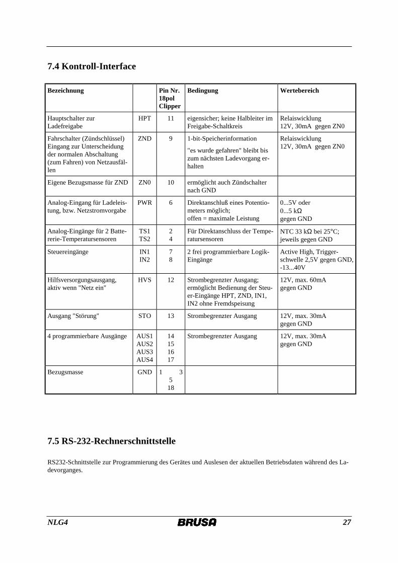
7.4 Kontroll-Interface
Bezeichnung Pin Nr. 18pol Clipper
Bedingung Wertebereich
Hauptschalter zur Ladefreigabe
HPT 11 eigensicher; keine Halbleiter im Freigabe-Schaltkreis
Relaiswicklung 12V, 30mA gegen ZN0
Fahrschalter (Zündschlüssel) Eingang zur Unterscheidung der normalen Abschaltung (zum Fahren) von Netzausfäl-len
ZND 9 1-bit-Speicherinformation
"es wurde gefahren" bleibt bis zum nächsten Ladevorgang er-halten
Relaiswicklung 12V, 30mA gegen ZN0
Eigene Bezugsmasse für ZND ZN0 10 ermöglicht auch Zündschalter nach GND
Analog-Eingang für Ladeleis-tung, bzw. Netzstromvorgabe
PWR 6 Direktanschluß eines Potentio-meters möglich; offen = maximale Leistung
0...5V oder 0...5 kΩ gegen GND
Analog-Eingänge für 2 Batte-rerie-Temperatursensoren
TS1 TS2
2 4
Für Direktanschluss der Tempe-ratursensoren
NTC 33 kΩ bei 25°C; jeweils gegen GND
Steuereingänge IN1 IN2
7 8
2 frei programmierbare Logik-Eingänge
Active High, Trigger-schwelle 2,5V gegen GND, -13...40V
Hilfsversorgungsausgang, aktiv wenn "Netz ein"
HVS 12 Strombegrenzter Ausgang; ermöglicht Bedienung der Steu-er-Eingänge HPT, ZND, IN1, IN2 ohne Fremdspeisung
12V, max. 60mA gegen GND
Ausgang "Störung" STO 13 Strombegrenzter Ausgang 12V, max. 30mA gegen GND
4 programmierbare Ausgänge AUS1 AUS2 AUS3 AUS4
14 15 16 17
Strombegrenzter Ausgang 12V, max. 30mA gegen GND
Bezugsmasse GND 1 3 5
18
7.5 RS-232-Rechnerschnittstelle RS232-Schnittstelle zur Programmierung des Gerätes und Auslesen der aktuellen Betriebsdaten während des La-devorganges.
NLG4 28
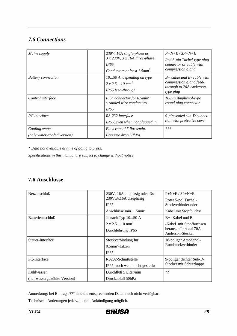
7.6 Connections Mains supply 230V, 16A single-phase or
3 x 230V, 3 x 16A three-phase IP65 Conductors at least 1.5mm2
P+N+E / 3P+N+E Red 5-pin Tuchel-type plug connector or cable with compression gland
Battery connection 10...50 A, depending on type 2 x 2.5....10 mm2 IP65 feed-through
B+ cable and B- cable with compression gland feed-through to 70A Anderson-type plug
Control interface Plug connector for 0.5mm2 stranded wire conductors IP65
18-pin Amphenol-type round plug connector
PC interface RS-232 interface IP65, even when not plugged in
9-pin sealed sub-D connec-tion with protective cover
Cooling water (only water-cooled version)
Flow rate of 5 litres/min. Pressure drop 50hPa
??*
* Data not available at time of going to press.
Specifications in this manual are subject to change without notice.
7.6 Anschlüsse Netzanschluß 230V, 16A einphasig oder 3x
230V,3x16A dreiphasig IP65 Anschlüsse min. 1.5mm2
P+N+E / 3P+N+E Roter 5-pol Tuchel-Steckverbinder oder Kabel mit Stopfbuchse
Batterieanschluß Je nach Typ 10...50 A 2 x 2.5....10 mm2 Durchführung IP65
B+ -Kabel und B- -Kabel mit Stopfbuchsen herausgeführt auf 70A-Anderson-Stecker
Steuer-Interface Steckverbindung für 0.5mm2-Litzen IP65
18-poliger Amphenol-Rundsteckverbinder
PC-Interface RS232-Schnittstelle IP65, auch wenn nicht gesteckt
9-poliger dichter Sub-D-Stecker mit Schutzkappe
Kühlwasser (nur wassergekühlte Version)
Durchfluß 5 Liter/min Druckabfall 50hPa
??
Anmerkung: bei Eintrag „??“ sind die entsprechenden Daten noch nicht verfügbar.
Technische Änderungen jederzeit ohne Ankündigung möglich.
NLG4 29
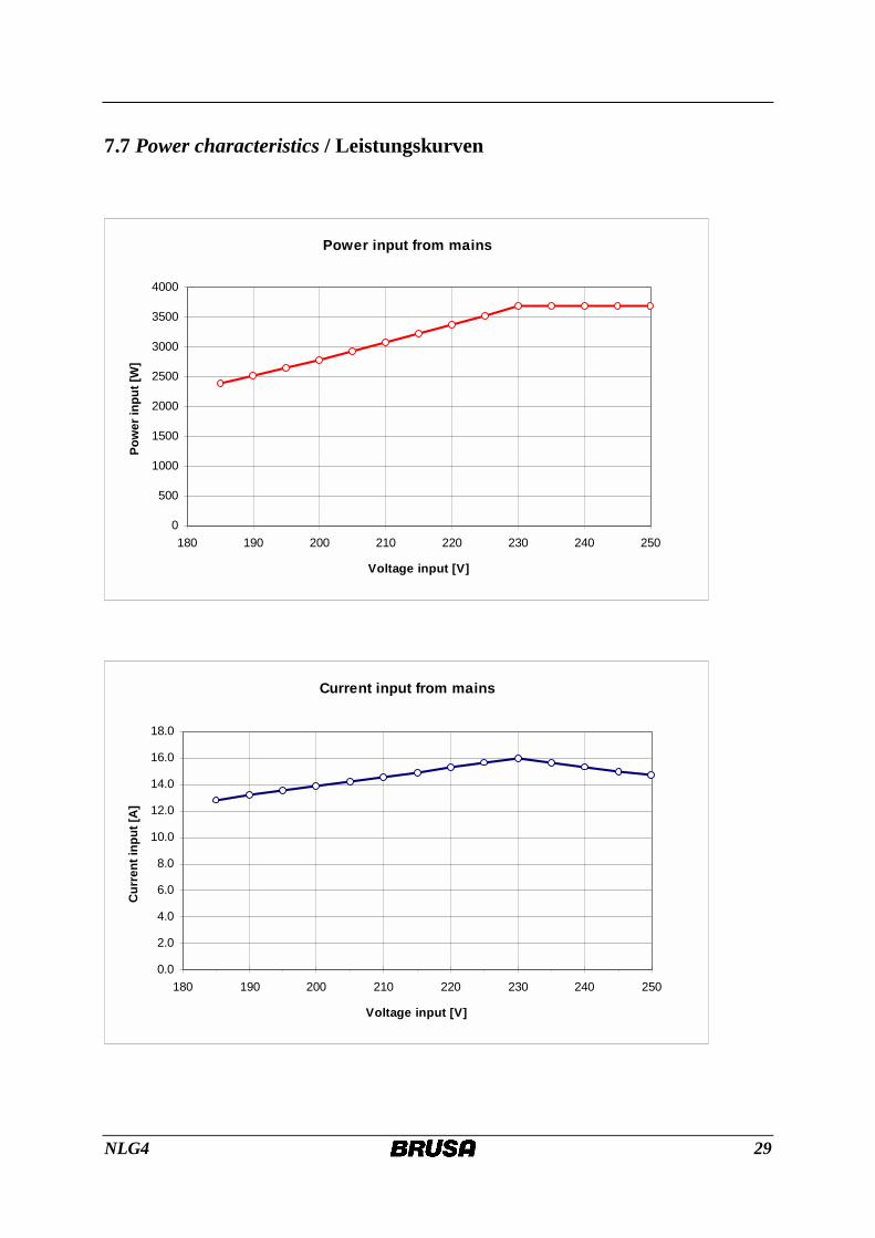
7.7 Power characteristics / Leistungskurven
Power input from mains
0
500
1000
1500
2000
2500
3000
3500
4000
180 190 200 210 220 230 240 250
Voltage input [V]
Pow
er in
put [
W]
Current input from mains
0.0
2.0
4.0
6.0
8.0
10.0
12.0
14.0
16.0
18.0
180 190 200 210 220 230 240 250
Voltage input [V]
Cur
rent
inpu
t [A
]
NLG4 30
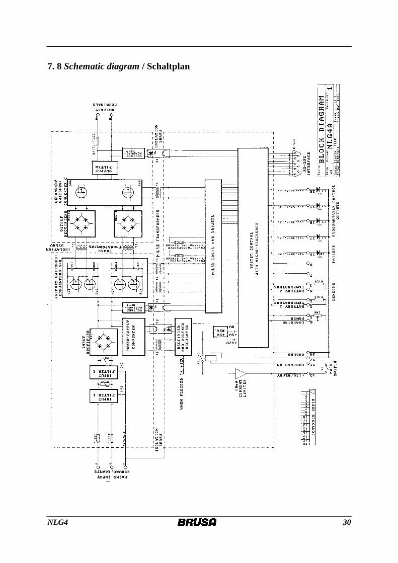
7. 8 Schematic diagram / Schaltplan
NLG4 31
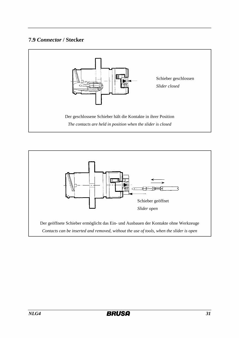
7.9 Connector / Stecker
Schieber geschlossen
Slider closed
Der geschlossene Schieber hält die Kontakte in ihrer Position
The contacts are held in position when the slider is closed
Der geöffnete Schieber ermöglicht das Ein- und Ausbauen der Kontakte ohne Werkzeuge
Contacts can be inserted and removed, without the use of tools, when the slider is open
Schieber geöffnet
Slider open
NLG4 32
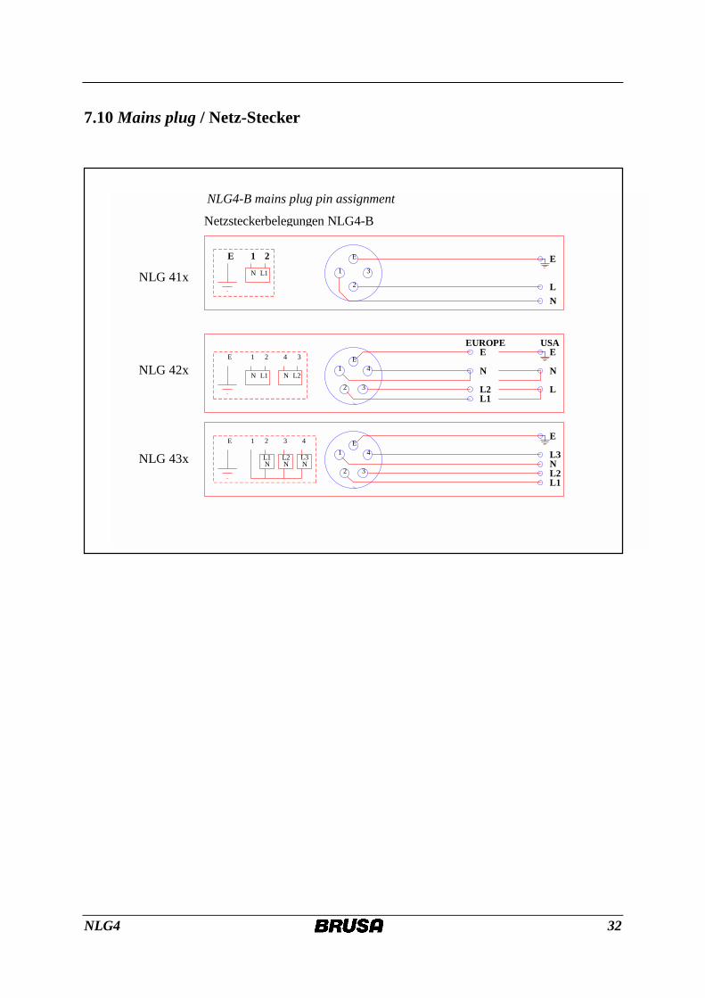
7.10 Mains plug / Netz-Stecker
1
2 3
4EE 2 4 31
L1 L2N N
1
2 3
4EE 2 431
L1 L2 L3N N N
Netzsteckerbelegungen NLG4-B
NLG 42x
NLG 43x
NLG 41x 1
2
3
EE 21
L1N
E
NL
E
N
L1L2
EUROPE USAE
N
L
E
N
L1L2
L3
NLG4-B mains plug pin assignment