Embed Size (px)
Citation preview

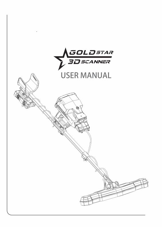
USER MANUAL
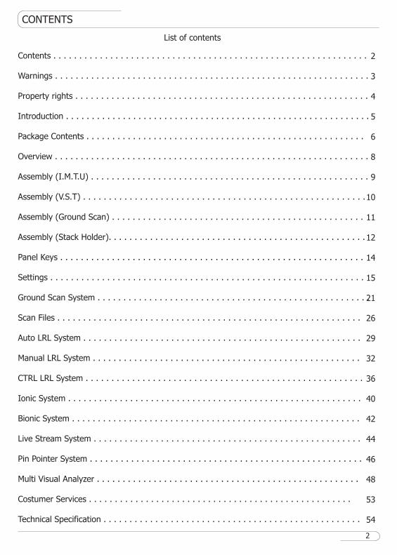
CONTENTS
List of contents
Contents . . . . . . . . . . . . . . . . . . . . . . . . . . . . . . . . . . . . . . . . . . . . . . . . . . . . . . . . . . . . .
Warnings . . . . . . . . . . . . . . . . . . . . . . . . . . . . . . . . . . . . . . . . . . . . . . . . . . . . . . . . . . . . .
Property rights . . . . . . . . . . . . . . . . . . . . . . . . . . . . . . . . . . . . . . . . . . . . . . . . . . . . . . . . .
Introduction . . . . . . . . . . . . . . . . . . . . . . . . . . . . . . . . . . . . . . . . . . . . . . . . . . . . . . . . . . .
Package Contents . . . . . . . . . . . . . . . . . . . . . . . . . . . . . . . . . . . . . . . . . . . . . . . . . . . . . .
Overview . . . . . . . . . . . . . . . . . . . . . . . . . . . . . . . . . . . . . . . . . . . . . . . . . . . . . . . . . . . . .
Assembly (I.M.T.U) . . . . . . . . . . . . . . . . . . . . . . . . . . . . . . . . . . . . . . . . . . . . . . . . . . . . . .
Assembly (V.S.T) . . . . . . . . . . . . . . . . . . . . . . . . . . . . . . . . . . . . . . . . . . . . . . . . . . . . . . .
Assembly (Ground Scan) . . . . . . . . . . . . . . . . . . . . . . . . . . . . . . . . . . . . . . . . . . . . . . . . .
Assembly (Stack Holder). . . . . . . . . . . . . . . . . . . . . . . . . . . . . . . . . . . . . . . . . . . . . . . . . .
Panel Keys . . . . . . . . . . . . . . . . . . . . . . . . . . . . . . . . . . . . . . . . . . . . . . . . . . . . . . . . . . .
Settings . . . . . . . . . . . . . . . . . . . . . . . . . . . . . . . . . . . . . . . . . . . . . . . . . . . . . . . . . . . . .
Ground Scan System . . . . . . . . . . . . . . . . . . . . . . . . . . . . . . . . . . . . . . . . . . . . . . . . . . . . .
Scan Files . . . . . . . . . . . . . . . . . . . . . . . . . . . . . . . . . . . . . . . . . . . . . . . . . . . . . . . . . . .
Auto LRL System . . . . . . . . . . . . . . . . . . . . . . . . . . . . . . . . . . . . . . . . . . . . . . . . . . . . . .
Manual LRL System . . . . . . . . . . . . . . . . . . . . . . . . . . . . . . . . . . . . . . . . . . . . . . . . . . . .
CTRL LRL System . . . . . . . . . . . . . . . . . . . . . . . . . . . . . . . . . . . . . . . . . . . . . . . . . . . . . .
Ionic System . . . . . . . . . . . . . . . . . . . . . . . . . . . . . . . . . . . . . . . . . . . . . . . . . . . . . . . . .
Bionic System . . . . . . . . . . . . . . . . . . . . . . . . . . . . . . . . . . . . . . . . . . . . . . . . . . . . . . . .
Live Stream System . . . . . . . . . . . . . . . . . . . . . . . . . . . . . . . . . . . . . . . . . . . . . . . . . . . .
Pin Pointer System . . . . . . . . . . . . . . . . . . . . . . . . . . . . . . . . . . . . . . . . . . . . . . . . . . . . .
Multi Visual Analyzer . . . . . . . . . . . . . . . . . . . . . . . . . . . . . . . . . . . . . . . . . . . . . . . . . . .
Costumer Services . . . . . . . . . . . . . . . . . . . . . . . . . . . . . . . . . . . . . . . . . . . . . . . . . . .
Technical Specification . . . . . . . . . . . . . . . . . . . . . . . . . . . . . . . . . . . . . . . . . . . . . . . . . .
2
3
4
5
6
8
9
10
11
12
14
15
21
26
29
32
36
40
42
44
46
48
53
54
2
WARNINGS
Do not assemble and operate the device before reading the user manual.
3
The device may only be dismantled or repaired by MEGA DETECTION Gmbh or its authorized service centers. Unauthorized disassociation / infiltration of the internal components of the main monitor or other units for any reason cancels the warranty.
Do not store the device and its components under extremely low or high temperatures for long periods (the preferred storage temperature is -20 ° C to 60 ° C / -4 ° F to 140 ° F).
Do not use the device indoors. The device may constantly give target signals indoors as there are many metals. Use the device outdoors, in open fields.
Do not submerge the device or its accessories in water. Do not expose the equipment to excessively moist environments.
Do not leave another detector or electromagnetic device close to the device (within a distance of less than 10 meters by 30 feet)
Protect the main unit of the device from impacts during normal use. For transportation, place the detector carefully in the original carton and secure with shock-resistant packaging.
Keep the device out of your shoes while walking. The device may detect minerals on you or inside your shoes as targets.

PROPERTY RIGHTS
Copyright © Mega Detection (© 2021 All Rights Reserved)
4
No part of this guide may be reproduced, including the products and programs described in it. Any use of material, reproduction, storage or translation of this information without prior permis-sion from MEGA DETECTION Gmbh is subject to legal liability of its owner.
MEGA DETECTION invites all users to ensure that the acquisition and use of this type of equipment complies with the laws and regulations of the countries in use and is not responsible for the legal consequences if the laws state otherwise.
MEGA DETECTION does not bear in all cases or any of its directors, officials, employees, and authorized agents indirect, special, incidental, or consequential damages (including damages for interest loss, business loss, loss of use or data, business interruption and the like), even if the company was notified of the possibility of such damages arising from any defect or error in this manual or product.
The specifications and information contained in this guide are published for information use only and are subject to update periodically at any time without notice to the user.
The products and company names that appear in this guide may be registered trademarks and copyrights are reserved for the related companies and mentioning them here is used only for identification and for the benefit of the owner, without intentionally infringing on the property rights of these companies.
MEGA DETECTION is not responsible for misunderstanding this manual or misusing the device in violation of the instructions in this guide.
INTRODUCTION
Ground Scan System
Auto Long Range Locator System
Manual Long Range Locator System
Control Long Range Locator System
Ionic System
Bionic System
Live Stream System
Pin Pointer System
5
With the engineering, research and development team at Mega Detection, a dream is now a reality with
Gold Star 3D Scanner.
A comprehensive metal detector with multiple detection technologies within one device that provides
prospectors with all the necessary tools to detect buried treasures.
The integrated Gold Star 3D Scanner contains eight different systems to search for gold, metal and
ancient archaeological burials with advanced technology and easy to use at the same time.
Thank you for choosing the Gold Star 3D Scanner product from Mega Detection. For more informa-
tion, you can visit our website.
PACKAGE CONTENT
1
23
5
A B
C
D
E
F
6
78
9
10
13
11
12
6
4
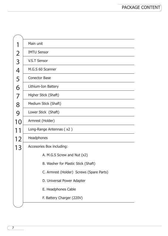
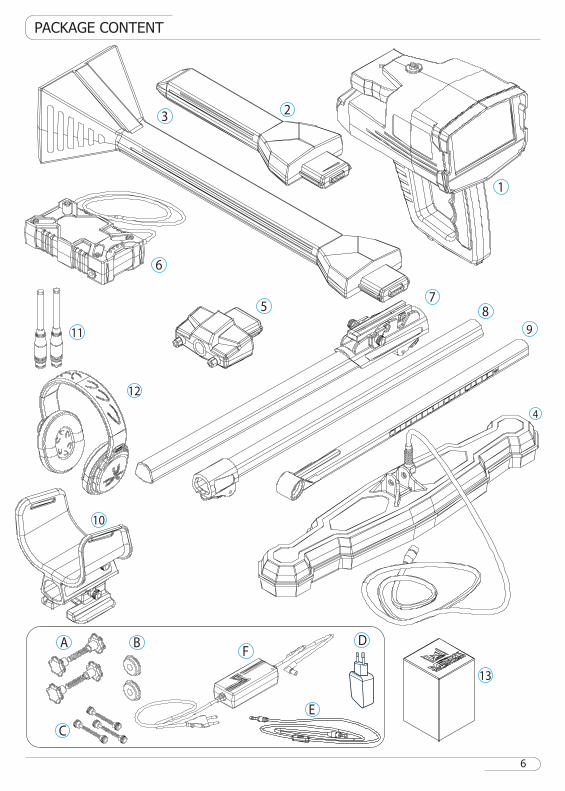
Main unit
IMTU Sensor
V.S.T Sensor
M.G.S 60 Scanner
Conector Base
Lithium-Ion Battery
Higher Stick (Shaft)
Medium Stick (Shaft)
Lower Stick (Shaft)
Armrest (Holder)
Long-Range Antennas ( x2 )
Headphones
Accesories Box including:
A. M.G.S Screw and Nut (x2)
B. Washer for Plastic Stick (Shaft)
C. Armrest (Holder) Screws (Spare Parts)
D. Universal Power Adapter
E. Headphones Cable
F. Battery Charger (220V)
1
2
3
4
5
6
7
8
9
10
11
12
13
PACKAGE CONTENT
7
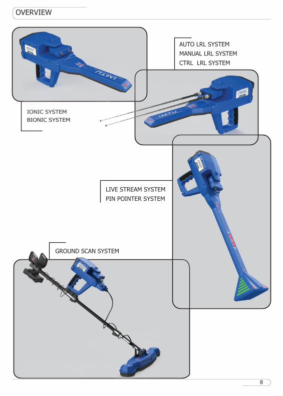
AUTO LRL SYSTEM
MANUAL LRL SYSTEM
CTRL LRL SYSTEM
LIVE STREAM SYSTEM
PIN POINTER SYSTEM
GROUND SCAN SYSTEM
IONIC SYSTEM
BIONIC SYSTEM
OVERVIEW
8
ASSEMBLY
1
2
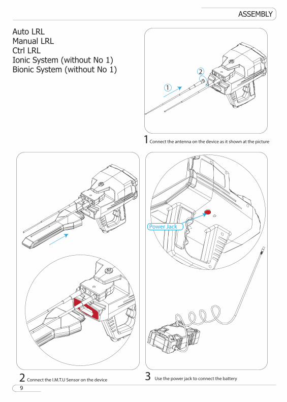
1Connect the antenna on the device as it shown at the picture
3 Use the power jack to connect the battery
Power Jack
2 Connect the I.M.T.U Sensor on the device
Auto LRLManual LRLCtrl LRLIonic System (without No 1)Bionic System (without No 1)
9
ASSEMBLY
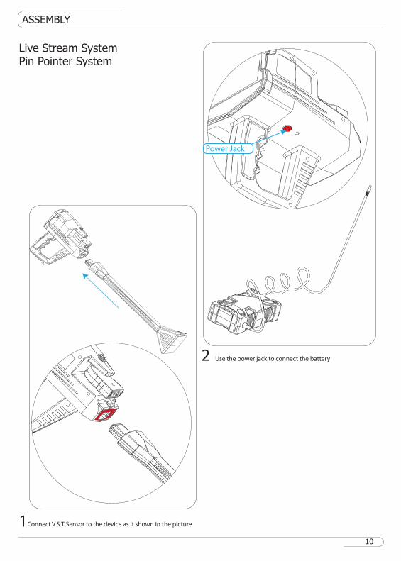
1Connect V.S.T Sensor to the device as it shown in the picture
2 Use the power jack to connect the battery
Live Stream SystemPin Pointer System
10
Power Jack
ASSEMBLY
1
2
3
4
65
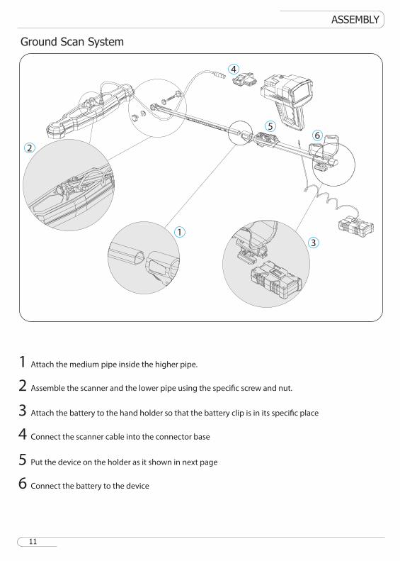
1 Attach the medium pipe inside the higher pipe.
2 Assemble the scanner and the lower pipe using the specific screw and nut.
3 Attach the battery to the hand holder so that the battery clip is in its specific place
4 Connect the scanner cable into the connector base
5 Put the device on the holder as it shown in next page
6 Connect the battery to the device
Ground Scan System
11
ASSEMBLY
1 2
3
1 2
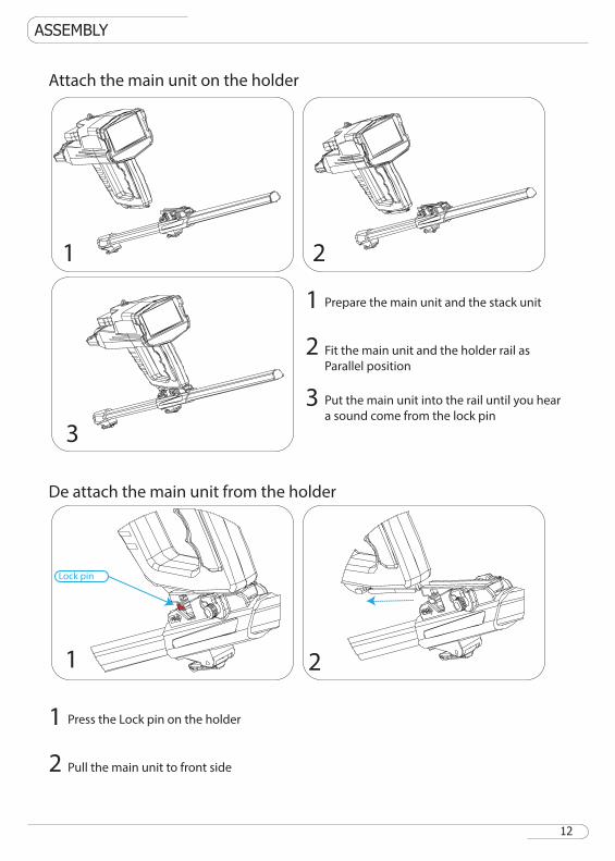
Attach the main unit on the holder
De attach the main unit from the holder
Lock pin
1 Prepare the main unit and the stack unit
2 Fit the main unit and the holder rail as
Parallel position
3 Put the main unit into the rail until you hear
a sound come from the lock pin
1 Press the Lock pin on the holder
2 Pull the main unit to front side
12
ASSEMBLY
1
1
2
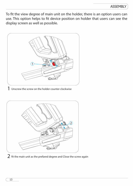
Unscrew the screw on the holder counter clockwise
2 fit the main unit as the prefared degree and Close the screw again
13
To fit the view degree of main unit on the holder, there is an option users can
use. This option helps to fit device position on holder that users can see the
display screen as well as possible.
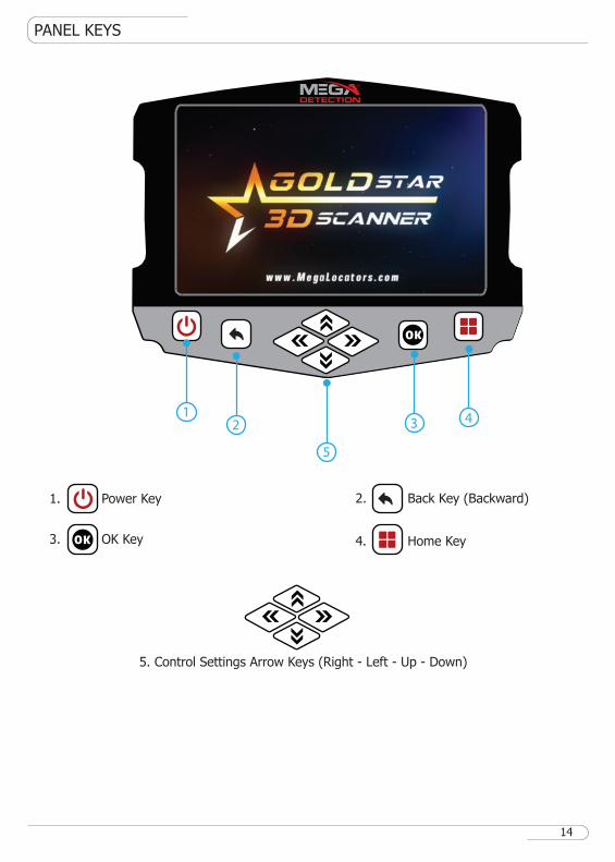
PANEL KEYS
1. Power Key
3. OK Key
2. Back Key (Backward)
4. Home Key
5. Control Settings Arrow Keys (Right - Left - Up - Down)
OK
OK
5
4321
14
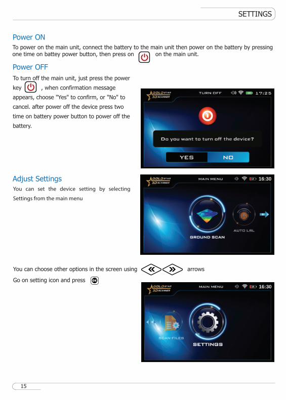
To turn off the main unit, just press the power
key , when confirmation message
appears, choose "Yes" to confirm, or "No" to
cancel. after power off the device press two
time on battery power button to power off the
battery.
SETTINGS
Power ON
Power OFF
Adjust Settings
You can choose other options in the screen using arrows
Go on setting icon and press OK
15
You can set the device setting by selecting
Settings from the main menu
To power on the main unit, connect the battery to the main unit then power on the battery by pressing one time on battey power button, then press on on the main unit.
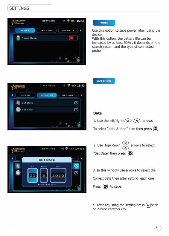
1. Use the left/right arrows To select “date & time” item then press
SETTINGS
Date
3. In this window use arrows to select the
Correct date then after setting each one
Press to save
2. Use top/ down arrows to select
“Set Date” then press
OK
OK
OK
16
4. After adjusting the setting press back on device controls key
Use this option to save power when using the device.With this option, the battery life can be increased by at least 50% , it depends on the search system and the type of connected probe
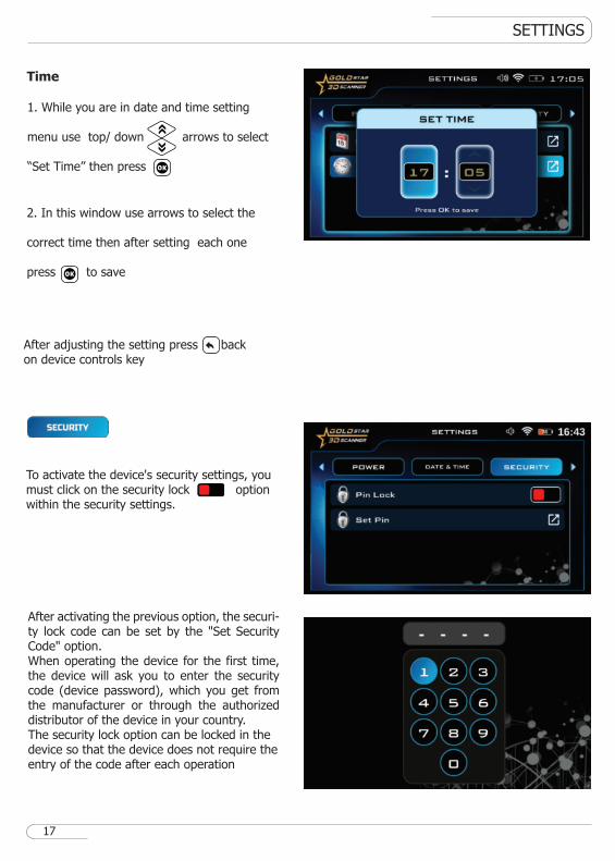
To activate the device's security settings, you must click on the security lock option within the security settings.
SETTINGS
Time
2. In this window use arrows to select the
correct time then after setting each one
press to save
1. While you are in date and time setting menu use top/ down arrows to select
“Set Time” then press OK
OK
17
After adjusting the setting press back on device controls key
After activating the previous option, the securi-ty lock code can be set by the "Set Security Code" option.When operating the device for the first time, the device will ask you to enter the security code (device password), which you get from the manufacturer or through the authorized distributor of the device in your country.The security lock option can be locked in the device so that the device does not require the entry of the code after each operation
SETTINGS
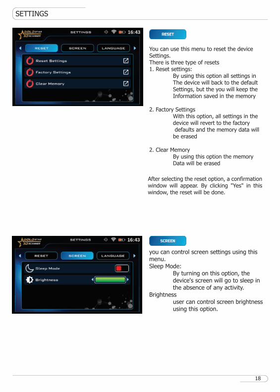
You can use this menu to reset the device Settings.There is three type of resets1. Reset settings: By using this option all settings in The device will back to the default Settings, but the you will keep the Information saved in the memory
2. Factory Settings With this option, all settings in the device will revert to the factory defaults and the memory data will be erased
2. Clear Memory By using this option the memory Data will be erased
you can control screen settings using thismenu.Sleep Mode: By turning on this option, the device's screen will go to sleep in the absence of any activity.Brightness user can control screen brightness using this option.
18
After selecting the reset option, a confirmation window will appear. By clicking "Yes" in this window, the reset will be done.
SETTINGS
19
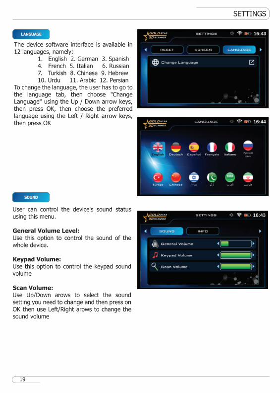
The device software interface is available in 12 languages, namely: 1. English 2. German 3. Spanish 4. French 5. Italian 6. Russian 7. Turkish 8. Chinese 9. Hebrew 10. Urdu 11. Arabic 12. PersianTo change the language, the user has to go to the language tab, then choose "Change Language" using the Up / Down arrow keys, then press OK, then choose the preferred language using the Left / Right arrow keys, then press OK
User can control the device's sound status using this menu.
General Volume Level:Use this option to control the sound of the whole device.
Keypad Volume:Use this option to control the keypad sound volume
Scan Volume:Use Up/Down arows to select the sound settıng you need to change and then press on OK then use Left/Right arows to change the sound volume
SETTINGS
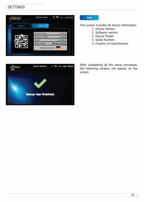
This screen includes all device information 1. Device Version 2. Software version 3. Device Model 4. Serial Number 5. Country of manufacturer
20
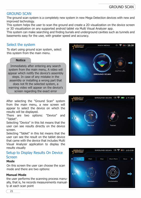
After completing all the setup processes, the following window will appear on the screen
GROUND SCAN
GROUND SCAN
Select the system
Mode
21
To start using ground scan system, select this system from the main menu.
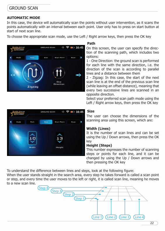
After selecting the "Ground Scan" system from the main menu, a new screen will appear to select the device on which the results will be displayed.There are two options: "Device" and "Tablet".Selecting "Device" in this list means that the user can see results directly on the device screen.Selecting "Tablet" in this list means that the user can see the result on the tablet device that came with the device that includes Multi Visual Analyzer application to display the results visually
On this screen the user can choose the scan mode and there are two options:
The ground scan system is a completely new system in new Mega Detection devices with new and improved technology.This system helps the user to scan the ground and create a 2D visualization on the device screen or 3D visualization on any supported android tablet via Multi Visual Analyzer app.This system can make searching and finding burials and underground cavities such as tunnels and basements easy for the user, with greater speed and accuracy.
Setup to Display Results On Device Screen
Manual Mode
the user performs the scanning process manu-ally, that is, he records measurements manual-ly at each scan point
Notice
Immediately after entering any search system from the main menu, A video will appear which notify the device's assembly
steps. In case of any mistake in the assembly or installing a wrong part that
does not fit the selected system, a warning video will appear on the device's
screen regarding the exact error
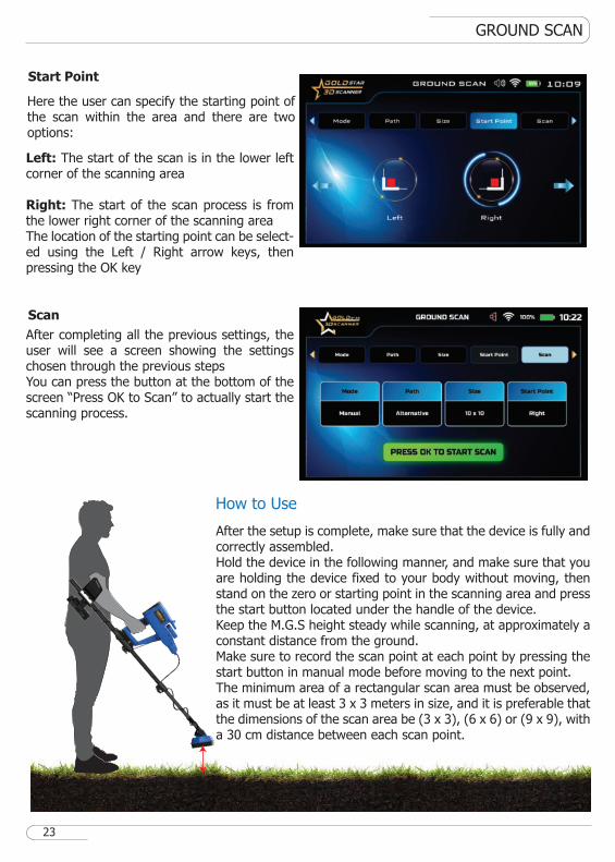
On this screen, the user can specify the direc-tion of the scanning path, which includes two options:1 - One Direction: the ground scan is performed for each line with the same direction, i.e. the direction of the scan is according to parallel lines and a distance between them2 - Zigzag: In this case, the start of the next scan line is at the end of the previous scan line (while leaving an offset distance), meaning that every two successive lines are scanned in an opposite direction.Select your preferred scan path mode using the Left / Right arrow keys, then press the OK key
The user can choose the dimensions of the scanning area using this screen, which are:
Width (Lines)It is the number of scan lines and can be set using the Up / Down arrows, then press the OK keyHeight (Steps)This number expresses the number of scanning steps or points for each line, and it can be changed by using the Up / Down arrows and then pressing the OK key
GROUND SCAN
AUTOMATIC MODE
Path
Size
Line 4Line 3Line 2Line 1
Step 1Step 2
Step 3Step 4
22
To understand the difference between lines and steps, look at the following figure:When the user stands straight in the search area, every step he takes forward is called a scan point or step, and every time the user moves to the left or right, it is called scan line, meaning he moves to a new scan line.
In this case, the device will automatically scan the points without user intervention, as it scans the points automatically with an interval between each point. User only has to press on start button at start of next scan line.
To choose the appropriate scan mode, use the Left / Right arrow keys, then press the OK key
GROUND SCAN
Start Point
Scan
How to Use
23
Here the user can specify the starting point of the scan within the area and there are two options:
Left: The start of the scan is in the lower left corner of the scanning area
Right: The start of the scan process is from the lower right corner of the scanning areaThe location of the starting point can be select-ed using the Left / Right arrow keys, then pressing the OK key
After completing all the previous settings, the user will see a screen showing the settings chosen through the previous stepsYou can press the button at the bottom of the screen “Press OK to Scan” to actually start the scanning process.
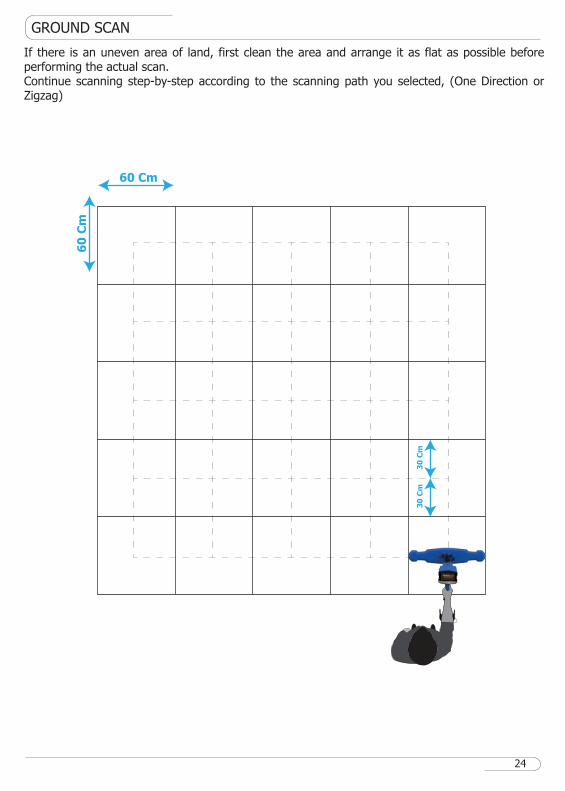
After the setup is complete, make sure that the device is fully and correctly assembled.Hold the device in the following manner, and make sure that you are holding the device fixed to your body without moving, then stand on the zero or starting point in the scanning area and press the start button located under the handle of the device.Keep the M.G.S height steady while scanning, at approximately a constant distance from the ground.Make sure to record the scan point at each point by pressing the start button in manual mode before moving to the next point.The minimum area of a rectangular scan area must be observed, as it must be at least 3 x 3 meters in size, and it is preferable that the dimensions of the scan area be (3 x 3), (6 x 6) or (9 x 9), with a 30 cm distance between each scan point.
GROUND SCAN
60
Cm
30
Cm
30
Cm
60 Cm
24
If there is an uneven area of land, first clean the area and arrange it as flat as possible before performing the actual scan.Continue scanning step-by-step according to the scanning path you selected, (One Direction or Zigzag)
GROUND SCAN
Line No
Step No
Search Value
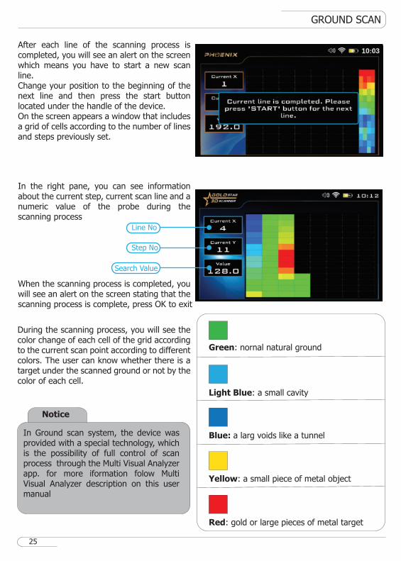
After each line of the scanning process is completed, you will see an alert on the screen which means you have to start a new scan line.Change your position to the beginning of the next line and then press the start button located under the handle of the device.On the screen appears a window that includes a grid of cells according to the number of lines and steps previously set.
In the right pane, you can see information about the current step, current scan line and a numeric value of the probe during the scanning process
When the scanning process is completed, you will see an alert on the screen stating that the scanning process is complete, press OK to exit
During the scanning process, you will see the color change of each cell of the grid according to the current scan point according to different colors. The user can know whether there is a target under the scanned ground or not by the color of each cell.
Red: gold or large pieces of metal target
Green: nornal natural ground
Light Blue: a small cavity
Blue: a larg voids like a tunnel
Yellow: a small piece of metal object
25
Notice
In Ground scan system, the device was provided with a special technology, which is the possibility of full control of scan process through the Multi Visual Analyzer app. for more iformation folow Multi Visual Analyzer description on this user manual
SCAN FILES
Scan Files
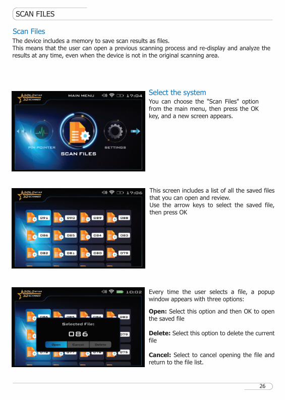
This screen includes a list of all the saved files that you can open and review.Use the arrow keys to select the saved file, then press OK
Every time the user selects a file, a popup window appears with three options:
Open: Select this option and then OK to open the saved file
Delete: Select this option to delete the current file
Cancel: Select to cancel opening the file and return to the file list.
You can choose the "Scan Files" option from the main menu, then press the OK key, and a new screen appears.
Select the system
26
The device includes a memory to save scan results as files. This means that the user can open a previous scanning process and re-display and analyze the results at any time, even when the device is not in the original scanning area.
SCAN FILES
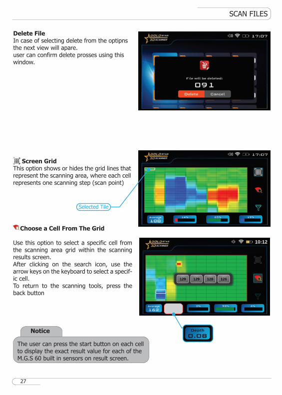
Screen GridThis option shows or hides the grid lines that represent the scanning area, where each cell represents one scanning step (scan point)
Choose a Cell From The Grid
Use this option to select a specific cell from the scanning area grid within the scanning results screen. After clicking on the search icon, use the arrow keys on the keyboard to select a specif-ic cell.To return to the scanning tools, press the back button
Selected Tile
27
Notice
The user can press the start button on each cell to display the exact result value for each of the M.G.S 60 built in sensors on result screen.
Delete FileIn case of selecting delete from the optipns the next view will apare.user can confirm delete prosses using this window.
SCAN FILES
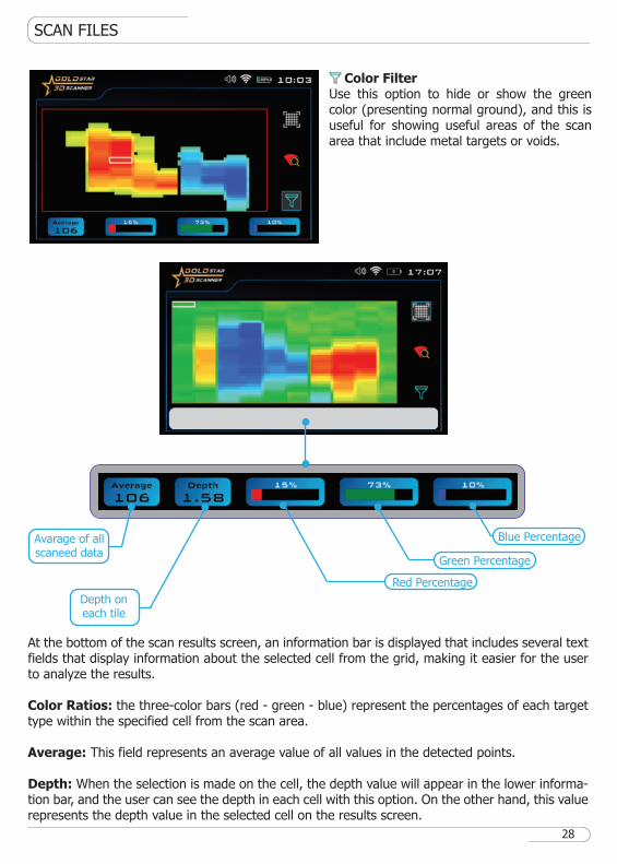
At the bottom of the scan results screen, an information bar is displayed that includes several text fields that display information about the selected cell from the grid, making it easier for the user to analyze the results.
Color Ratios: the three-color bars (red - green - blue) represent the percentages of each target type within the specified cell from the scan area.
Average: This field represents an average value of all values in the detected points.
Depth: When the selection is made on the cell, the depth value will appear in the lower informa-tion bar, and the user can see the depth in each cell with this option. On the other hand, this value represents the depth value in the selected cell on the results screen.
Color FilterUse this option to hide or show the green color (presenting normal ground), and this is useful for showing useful areas of the scan area that include metal targets or voids.
Avarage of all scaneed data
Depth on each tile
Red Percentage
Green Percentage
Blue Percentage
28
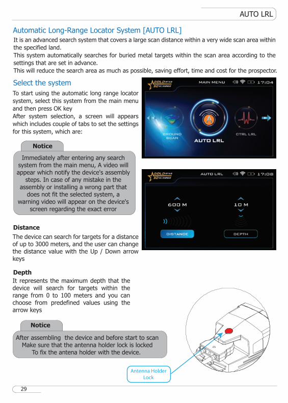
The device can search for targets for a distance of up to 3000 meters, and the user can change the distance value with the Up / Down arrow keys
It represents the maximum depth that the device will search for targets within the range from 0 to 100 meters and you can choose from predefined values using the arrow keys
AUTO LRL
Select the system
Automatic Long-Range Locator System [AUTO LRL]
Distance
Depth
After assembling the device and before start to scanMake sure that the antenna holder lock is locked
To fix the antena holder with the device.
Notice
Antenna Holder
Lock
It is an advanced search system that covers a large scan distance within a very wide scan area within
the specified land.
This system automatically searches for buried metal targets within the scan area according to the
settings that are set in advance.
This will reduce the search area as much as possible, saving effort, time and cost for the prospector.
29
To start using the automatic long range locator
system, select this system from the main menu
and then press OK key
After system selection, a screen will appears
which includes couple of tabs to set the settings
for this system, which are:
Notice
Immediately after entering any search system from the main menu, A video will appear which notify the device's assembly
steps. In case of any mistake in the assembly or installing a wrong part that
does not fit the selected system, a warning video will appear on the device's
screen regarding the exact error
AUTO LRL
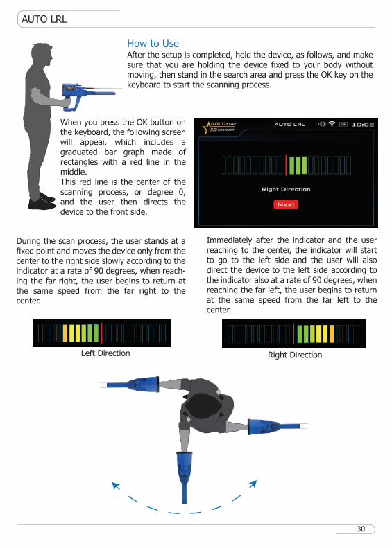
How to Use
Right DirectionLeft Direction
During the scan process, the user stands at a fixed point and moves the device only from the center to the right side slowly according to the indicator at a rate of 90 degrees, when reach-ing the far right, the user begins to return at the same speed from the far right to the center.
Immediately after the indicator and the user reaching to the center, the indicator will start to go to the left side and the user will also direct the device to the left side according to the indicator also at a rate of 90 degrees, when reaching the far left, the user begins to return at the same speed from the far left to the center.
After the setup is completed, hold the device, as follows, and make sure that you are holding the device fixed to your body without moving, then stand in the search area and press the OK key on the keyboard to start the scanning process.
When you press the OK button on the keyboard, the following screen will appear, which includes a graduated bar graph made of rectangles with a red line in the middle.This red line is the center of the scanning process, or degree 0, and the user then directs the device to the front side.
30
After assembling the device and before start to scanMake sure that the antenna holder lock is locked
To fix the antena holder with the device.
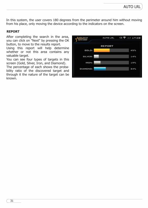
After completing the search in the area, you can click on "Next" by pressing the OK button, to move to the results report.Using this report will help determine whether or not this area contains any valuable target.You can see four types of targets in this screen (Gold, Silver, Iron, and Diamond).The percentage of each shows the proba-bility ratio of the discovered target and through it the nature of the target can be known.
In this system, the user covers 180 degrees from the perimeter around him without moving from his place, only moving the device according to the indicators on the screen.
AUTO LRL
REPORT
31
CTRL LRL
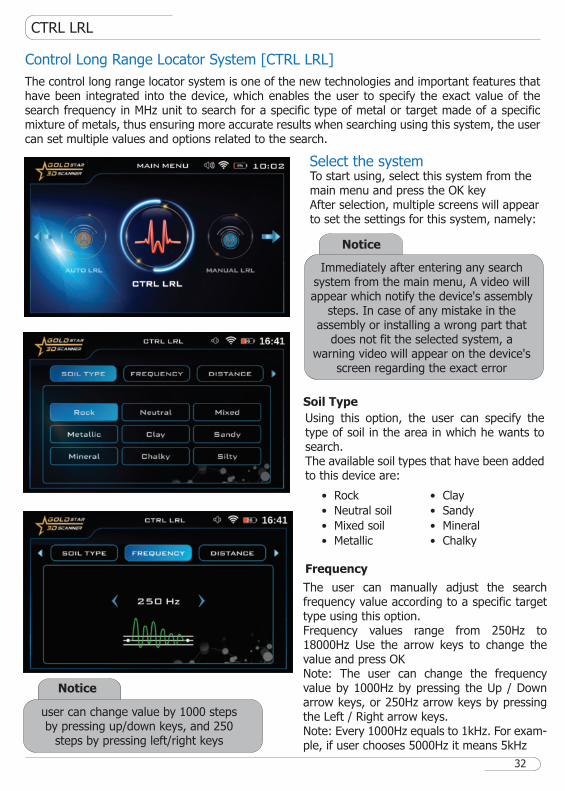
Control Long Range Locator System [CTRL LRL]
Select the system
The control long range locator system is one of the new technologies and important features that have been integrated into the device, which enables the user to specify the exact value of the search frequency in MHz unit to search for a specific type of metal or target made of a specific mixture of metals, thus ensuring more accurate results when searching using this system, the user can set multiple values and options related to the search.
Soil Type
Using this option, the user can specify the type of soil in the area in which he wants to search.The available soil types that have been added to this device are:
To start using, select this system from the main menu and press the OK keyAfter selection, multiple screens will appear to set the settings for this system, namely:
Frequency
The user can manually adjust the search frequency value according to a specific target type using this option.Frequency values range from 250Hz to 18000Hz Use the arrow keys to change the value and press OKNote: The user can change the frequency value by 1000Hz by pressing the Up / Down arrow keys, or 250Hz arrow keys by pressing the Left / Right arrow keys.Note: Every 1000Hz equals to 1kHz. For exam-ple, if user chooses 5000Hz it means 5kHz
32
Notice
user can change value by 1000 steps by pressing up/down keys, and 250
steps by pressing left/right keys
� Rock
� Neutral soil
� Mixed soil
� Metallic
� Clay
� Sandy
� Mineral
� Chalky
Notice
Immediately after entering any search system from the main menu, A video will appear which notify the device's assembly
steps. In case of any mistake in the assembly or installing a wrong part that
does not fit the selected system, a warning video will appear on the device's
screen regarding the exact error
CTRL LRL
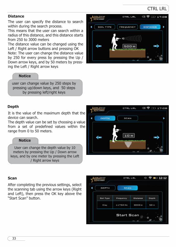
Depth
Distance
The user can specify the distance to search within during the search process.This means that the user can search within a radius of this distance, and this distance starts from 250 to 3000 metersThe distance value can be changed using the Left / Right arrow buttons and pressing OKNote: The user can change the distance value by 250 for every press by pressing the Up / Down arrow keys, and by 50 meters by press-ing the Left / Right arrow keys
It is the value of the maximum depth that the device can search.The depth value can be set by choosing a value from a set of predefined values within the range from 0 to 50 meters.
Scan
After completing the previous settings, select the scanning tab using the arrow keys (Right and Left), then press the OK key above the “Start Scan” button.
33
Notice
user can change value by 250 steps by pressing up/down keys, and 50 steps
by pressing left/right keys
Notice
User can change the depth value by 10 meters by pressing the Up / Down arrow
keys, and by one meter by pressing the Left / Right arrow keys
CTRL LRL
Notice
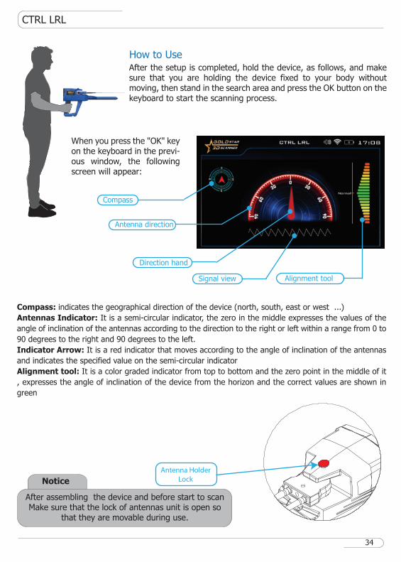
Antenna Holder
Lock
After assembling the device and before start to scanMake sure that the lock of antennas unit is open so
that they are movable during use.
How to UseAfter the setup is completed, hold the device, as follows, and make sure that you are holding the device fixed to your body without moving, then stand in the search area and press the OK button on the keyboard to start the scanning process.
When you press the "OK" key on the keyboard in the previ-ous window, the following screen will appear:
Compass
Antenna direction
Signal view
Direction hand
Alignment tool
34
Compass: indicates the geographical direction of the device (north, south, east or west ...)
Antennas Indicator: It is a semi-circular indicator, the zero in the middle expresses the values of the
angle of inclination of the antennas according to the direction to the right or left within a range from 0 to
90 degrees to the right and 90 degrees to the left.
Indicator Arrow: It is a red indicator that moves according to the angle of inclination of the antennas
and indicates the specified value on the semi-circular indicator
Alignment tool: It is a color graded indicator from top to bottom and the zero point in the middle of it
, expresses the angle of inclination of the device from the horizon and the correct values are shown in
green
CTRL LRL
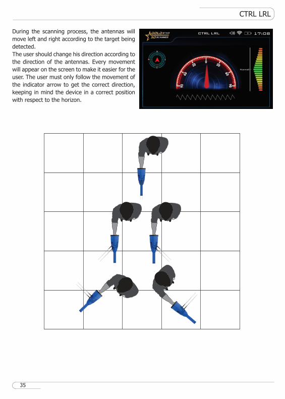
During the scanning process, the antennas will
move left and right according to the target being
detected.
The user should change his direction according to
the direction of the antennas. Every movement
will appear on the screen to make it easier for the
user. The user must only follow the movement of
the indicator arrow to get the correct direction,
keeping in mind the device in a correct position
with respect to the horizon.
35
MANUAL LRL
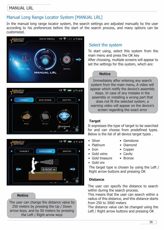
Manual Long Range Locator System [MANUAL LRL]
Select the system
In the manual long range locator system, the search settings are adjusted manually by the user according to his preferences before the start of the search process, and many options can be customized.
Target
It expresses the type of target to be searched for and can choose from predefined types. Below is the list of all device target types .
The target type is chosen by using the Left / Right arrow buttons and pressing OK
Distance
The user can specify the distance to search within during the search process.This means that the user can search within a radius of this distance, and this distance starts from 250 to 3000 metersThe distance value can be changed using the Left / Right arrow buttons and pressing OK
36
Notice
The user can change the distance value by 250 meters by pressing the Up / Down
arrow keys, and by 50 meters by pressing the Left / Right arrow keys
� Silver
� Platinum
� Iron
� Gold veins
� Gold treasure
� Gold ore
� Gemstone
� Diamond
� Copper
� Cavity
� Bronze
To start using, select this system from the
main menu and press the OK key
After choosing, multiple screens will appear to
set the settings for this system, which are:
Notice
Immediately after entering any search system from the main menu, A video will appear which notify the device's assembly
steps. In case of any mistake in the assembly or installing a wrong part that
does not fit the selected system, a warning video will appear on the device's
screen regarding the exact error
MANUAL LRL
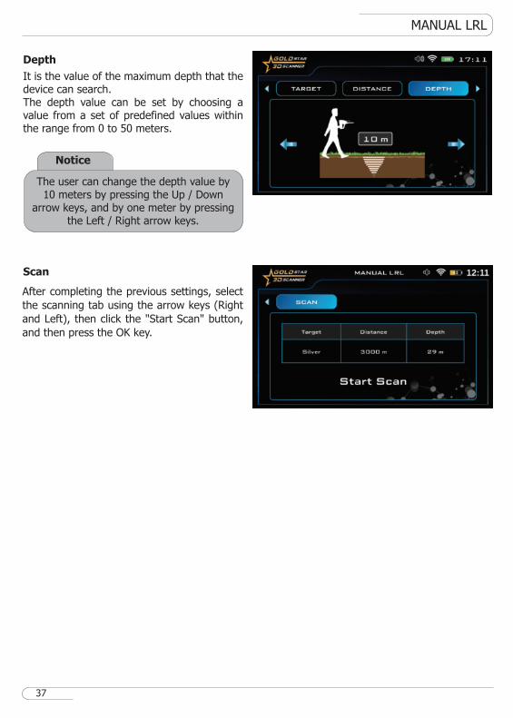
Depth
Scan
It is the value of the maximum depth that the device can search.The depth value can be set by choosing a value from a set of predefined values within the range from 0 to 50 meters.
37
Notice
The user can change the depth value by 10 meters by pressing the Up / Down
arrow keys, and by one meter by pressing the Left / Right arrow keys.
After completing the previous settings, select
the scanning tab using the arrow keys (Right
and Left), then click the "Start Scan" button,
and then press the OK key.
MANUAL LRL
38
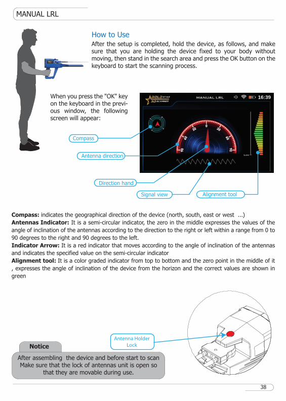
Notice
Antenna Holder
Lock
After assembling the device and before start to scanMake sure that the lock of antennas unit is open so
that they are movable during use.
How to UseAfter the setup is completed, hold the device, as follows, and make sure that you are holding the device fixed to your body without moving, then stand in the search area and press the OK button on the keyboard to start the scanning process.
When you press the "OK" key on the keyboard in the previ-ous window, the following screen will appear:
Compass
Antenna direction
Signal view
Direction hand
Alignment tool
Compass: indicates the geographical direction of the device (north, south, east or west ...)
Antennas Indicator: It is a semi-circular indicator, the zero in the middle expresses the values of the
angle of inclination of the antennas according to the direction to the right or left within a range from 0 to
90 degrees to the right and 90 degrees to the left.
Indicator Arrow: It is a red indicator that moves according to the angle of inclination of the antennas
and indicates the specified value on the semi-circular indicator
Alignment tool: It is a color graded indicator from top to bottom and the zero point in the middle of it
, expresses the angle of inclination of the device from the horizon and the correct values are shown in
green
MANUAL LRL
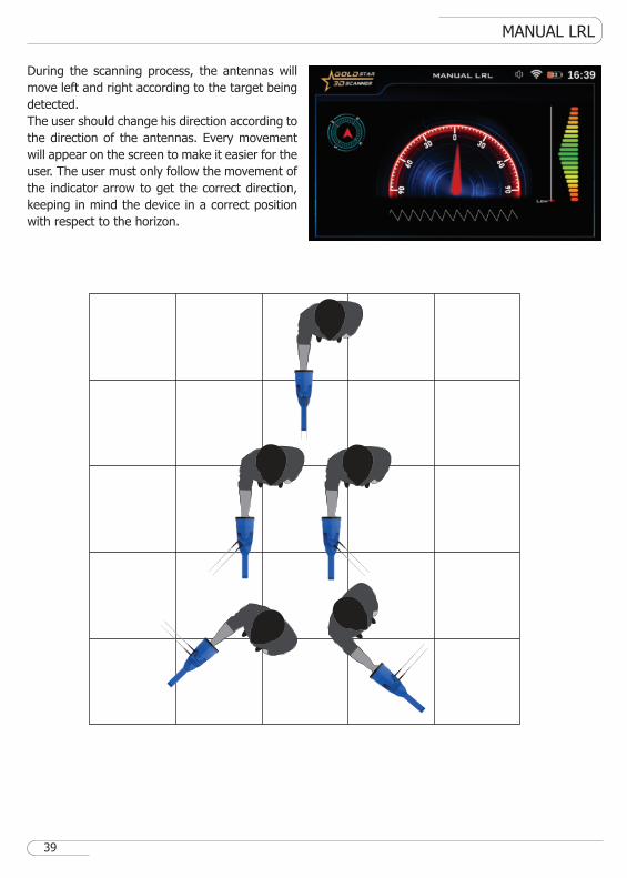
During the scanning process, the antennas will
move left and right according to the target being
detected.
The user should change his direction according to
the direction of the antennas. Every movement
will appear on the screen to make it easier for the
user. The user must only follow the movement of
the indicator arrow to get the correct direction,
keeping in mind the device in a correct position
with respect to the horizon.
39
IONIC
Select the system
IONIC
Gain
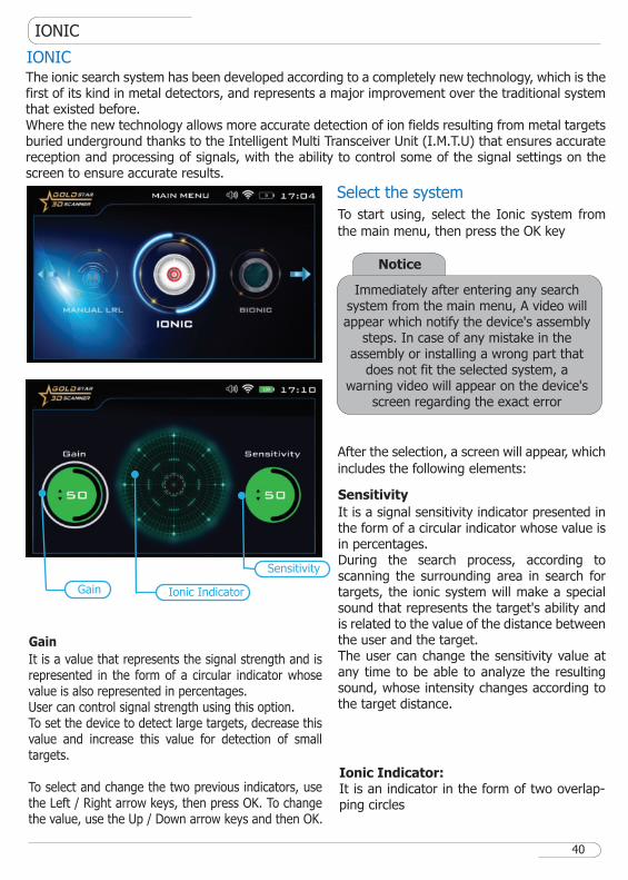
The ionic search system has been developed according to a completely new technology, which is the first of its kind in metal detectors, and represents a major improvement over the traditional system that existed before.Where the new technology allows more accurate detection of ion fields resulting from metal targets buried underground thanks to the Intelligent Multi Transceiver Unit (I.M.T.U) that ensures accurate reception and processing of signals, with the ability to control some of the signal settings on the screen to ensure accurate results.
Sensitivity
It is a signal sensitivity indicator presented in the form of a circular indicator whose value is in percentages.During the search process, according to scanning the surrounding area in search for targets, the ionic system will make a special sound that represents the target's ability and is related to the value of the distance between the user and the target.The user can change the sensitivity value at any time to be able to analyze the resulting sound, whose intensity changes according to the target distance.
Ionic Indicator:It is an indicator in the form of two overlap-ping circles
Sensitivity
Gain Ionic Indicator
40
To start using, select the Ionic system from
the main menu, then press the OK key
After the selection, a screen will appear, which
includes the following elements:
It is a value that represents the signal strength and is represented in the form of a circular indicator whose value is also represented in percentages.User can control signal strength using this option.To set the device to detect large targets, decrease this value and increase this value for detection of small targets.
To select and change the two previous indicators, use the Left / Right arrow keys, then press OK. To change the value, use the Up / Down arrow keys and then OK.
Notice
Immediately after entering any search system from the main menu, A video will appear which notify the device's assembly
steps. In case of any mistake in the assembly or installing a wrong part that
does not fit the selected system, a warning video will appear on the device's
screen regarding the exact error
IONIC
Notice
Antenna Holder
Lock
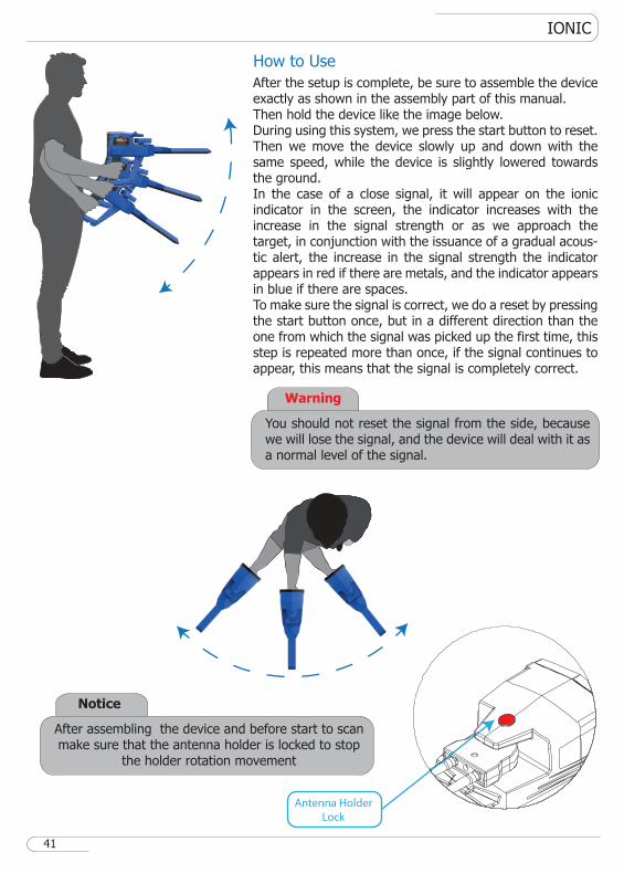
After assembling the device and before start to scan make sure that the antenna holder is locked to stop
the holder rotation movement
How to Use
After the setup is complete, be sure to assemble the device exactly as shown in the assembly part of this manual.Then hold the device like the image below.During using this system, we press the start button to reset. Then we move the device slowly up and down with the same speed, while the device is slightly lowered towards the ground.In the case of a close signal, it will appear on the ionic indicator in the screen, the indicator increases with the increase in the signal strength or as we approach the target, in conjunction with the issuance of a gradual acous-tic alert, the increase in the signal strength the indicator appears in red if there are metals, and the indicator appears in blue if there are spaces.To make sure the signal is correct, we do a reset by pressing the start button once, but in a different direction than the one from which the signal was picked up the first time, this step is repeated more than once, if the signal continues to appear, this means that the signal is completely correct.
41
Warning
You should not reset the signal from the side, because we will lose the signal, and the device will deal with it as a normal level of the signal.
BIONIC
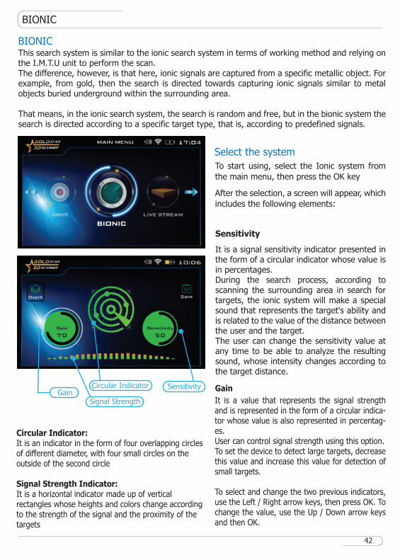
BIONICThis search system is similar to the ionic search system in terms of working method and relying on the I.M.T.U unit to perform the scan.The difference, however, is that here, ionic signals are captured from a specific metallic object. For example, from gold, then the search is directed towards capturing ionic signals similar to metal objects buried underground within the surrounding area.
That means, in the ionic search system, the search is random and free, but in the bionic system the search is directed according to a specific target type, that is, according to predefined signals.
SensitivityGain
Signal Strength
Circular Indicator
42
Select the system
Gain
Sensitivity
It is a signal sensitivity indicator presented in the form of a circular indicator whose value is in percentages.During the search process, according to scanning the surrounding area in search for targets, the ionic system will make a special sound that represents the target's ability and is related to the value of the distance between the user and the target.The user can change the sensitivity value at any time to be able to analyze the resulting sound, whose intensity changes according to the target distance.
To start using, select the Ionic system from
the main menu, then press the OK key
After the selection, a screen will appear, which
includes the following elements:
It is a value that represents the signal strength and is represented in the form of a circular indica-tor whose value is also represented in percentag-es.User can control signal strength using this option.To set the device to detect large targets, decrease this value and increase this value for detection of small targets.
To select and change the two previous indicators, use the Left / Right arrow keys, then press OK. To change the value, use the Up / Down arrow keys and then OK.
Circular Indicator:It is an indicator in the form of four overlapping circles of different diameter, with four small circles on the outside of the second circle
Signal Strength Indicator:It is a horizontal indicator made up of vertical rectangles whose heights and colors change according to the strength of the signal and the proximity of the targets
BIONIC
Notice
Antenna Holder
Lock
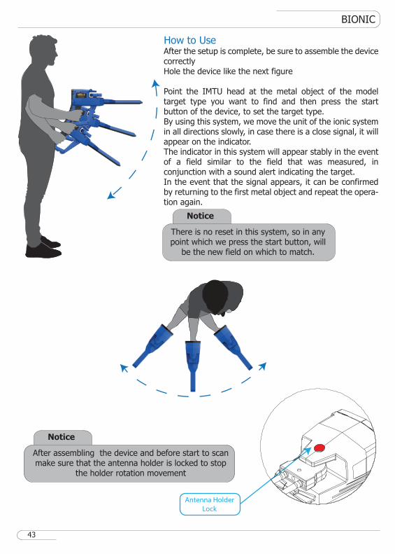
After assembling the device and before start to scan make sure that the antenna holder is locked to stop
the holder rotation movement
How to UseAfter the setup is complete, be sure to assemble the device correctly Hole the device like the next figure
Point the IMTU head at the metal object of the model target type you want to find and then press the start button of the device, to set the target type.By using this system, we move the unit of the ionic system in all directions slowly, in case there is a close signal, it will appear on the indicator.The indicator in this system will appear stably in the event of a field similar to the field that was measured, in conjunction with a sound alert indicating the target.In the event that the signal appears, it can be confirmed by returning to the first metal object and repeat the opera-tion again.
43
Notice
There is no reset in this system, so in any point which we press the start button, will
be the new field on which to match.
LIVE STREAM
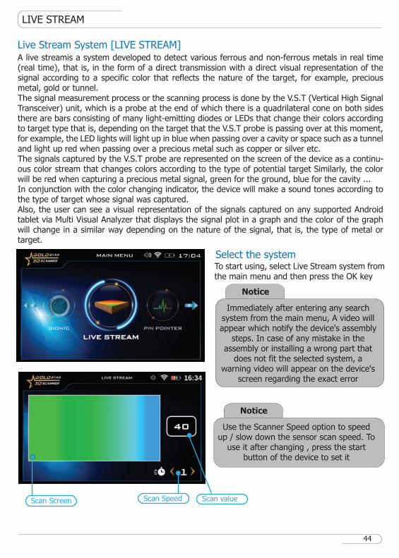
Live Stream System [LIVE STREAM]A live streamis a system developed to detect various ferrous and non-ferrous metals in real time (real time), that is, in the form of a direct transmission with a direct visual representation of the signal according to a specific color that reflects the nature of the target, for example, precious metal, gold or tunnel.The signal measurement process or the scanning process is done by the V.S.T (Vertical High Signal Transceiver) unit, which is a probe at the end of which there is a quadrilateral cone on both sides there are bars consisting of many light-emitting diodes or LEDs that change their colors according to target type that is, depending on the target that the V.S.T probe is passing over at this moment, for example, the LED lights will light up in blue when passing over a cavity or space such as a tunnel and light up red when passing over a precious metal such as copper or silver etc.The signals captured by the V.S.T probe are represented on the screen of the device as a continu-ous color stream that changes colors according to the type of potential target Similarly, the color will be red when capturing a precious metal signal, green for the ground, blue for the cavity ...In conjunction with the color changing indicator, the device will make a sound tones according to the type of target whose signal was captured.Also, the user can see a visual representation of the signals captured on any supported Android tablet via Multi Visual Analyzer that displays the signal plot in a graph and the color of the graph will change in a similar way depending on the nature of the signal, that is, the type of metal or target.
To start using, select Live Stream system from the main menu and then press the OK key
Select the system
44
Notice
Use the Scanner Speed option to speed up / slow down the sensor scan speed. To
use it after changing , press the start button of the device to set it
Notice
Immediately after entering any search system from the main menu, A video will appear which notify the device's assembly
steps. In case of any mistake in the assembly or installing a wrong part that
does not fit the selected system, a warning video will appear on the device's
screen regarding the exact error
Scan Screen Scan valueScan Speed
LIVE STREAM
How to Use
After the setup is complete, be sure to assemble the device exactly as shown in the assembly part of this manual.When setting up complete point the VST sensor vertically on the ground and start the scan process.Make sure that there are no metal objects in your shoes and keep the distance between the probe and the ground constant. also, during this procedure, the V.S.T Sensor should point vertically towards the ground, it should not rotate or pivot or even swing. during the operation you will see the color change in the device screen and according to the color change, the user can know whether there is a target underground or not.On the right side of the screen, there is 3 boxes which are:Value: It directly indicates the value of the signal captured by the search sensor. The colors of the indicator change according to the change of these values.Speed: Use the scanner speed option to speed up / slow down the speed of the sensor scan, any change in the speed will ask the user to press the start button to apply the new changes.Sensitivity: Use the sensitivity option to increase or decrease the sensitivity of the search sensor. Any change in the sensitivity will ask the user to press the start button to apply the new options.
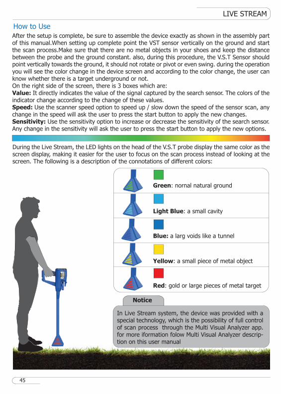
During the Live Stream, the LED lights on the head of the V.S.T probe display the same color as the screen display, making it easier for the user to focus on the scan process instead of looking at the screen. The following is a description of the connotations of different colors:
Red: gold or large pieces of metal target
Green: nornal natural ground
Light Blue: a small cavity
Blue: a larg voids like a tunnel
Yellow: a small piece of metal object
45
Notice
In Live Stream system, the device was provided with a special technology, which is the possibility of full control of scan process through the Multi Visual Analyzer app. for more iformation folow Multi Visual Analyzer descrip-tion on this user manual
PIN POINTER
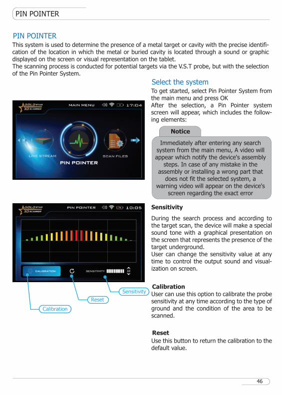
PIN POINTERThis system is used to determine the presence of a metal target or cavity with the precise identifi-cation of the location in which the metal or buried cavity is located through a sound or graphic displayed on the screen or visual representation on the tablet.The scanning process is conducted for potential targets via the V.S.T probe, but with the selection of the Pin Pointer System.
To get started, select Pin Pointer System from the main menu and press OKAfter the selection, a Pin Pointer system screen will appear, which includes the follow-ing elements:
Select the system
Sensitivity
Calibration
During the search process and according to the target scan, the device will make a special sound tone with a graphical presentation on the screen that represents the presence of the target underground.User can change the sensitivity value at any time to control the output sound and visual-ization on screen.
Reset
Use this button to return the calibration to the default value.
User can use this option to calibrate the probe sensitivity at any time according to the type of ground and the condition of the area to be scanned.
Calibration
Reset
Sensitivity
46
Notice
Immediately after entering any search system from the main menu, A video will appear which notify the device's assembly
steps. In case of any mistake in the assembly or installing a wrong part that
does not fit the selected system, a warning video will appear on the device's
screen regarding the exact error
PIN POINTER
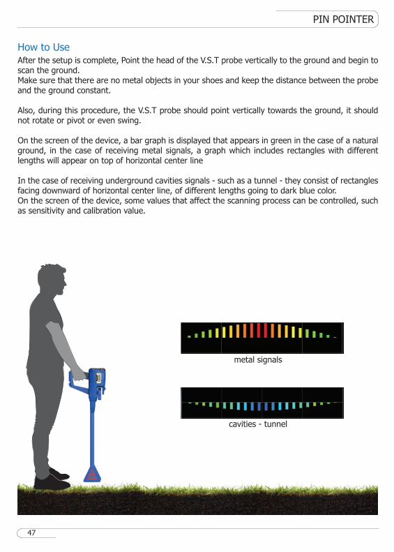
cavities - tunnel
metal signals
How to Use
After the setup is complete, Point the head of the V.S.T probe vertically to the ground and begin to scan the ground.Make sure that there are no metal objects in your shoes and keep the distance between the probe and the ground constant.
Also, during this procedure, the V.S.T probe should point vertically towards the ground, it should not rotate or pivot or even swing.
On the screen of the device, a bar graph is displayed that appears in green in the case of a natural ground, in the case of receiving metal signals, a graph which includes rectangles with different lengths will appear on top of horizontal center line
In the case of receiving underground cavities signals - such as a tunnel - they consist of rectangles facing downward of horizontal center line, of different lengths going to dark blue color.On the screen of the device, some values that affect the scanning process can be controlled, such as sensitivity and calibration value.
47
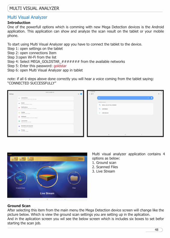
Multi Visual AnalyzerIntroductionOne of the powerfull options which is comming with new Mega Detection devices is the Android application. This application can show and analyze the scan result on the tablet or your mobile phone.
To start using Multi Visual Analyzer app you have to connect the tablet to the device.Step 1: open settings on the tabletStep 2: open connections ItemStep 3:open Wi-Fi from the listStep 4: Select MEGA_GOLDSTAR_####### from the available networksStep 5: Enter this password: goldstarStep 6: open Multi Visual Analyzer app in tablet
note: if all 6 steps above done correctly you will hear a voice coming from the tablet saying:“CONNECTED SUCCESSFULLY”
Ground ScanAfter selecting this item from the main menu the Mega Detection device screen will change like the picture below. Which is view the ground scan settings you are setting up in the aplication.And in the aplication screen you wil see the below screen which is includes six boxes to set befor starting the scan job.
Multi visual analyzer application contains 4 options as below:1. Ground scan2. Scanned Files3. Live Stream
MULTI VISUAL ANALYZER
48

A.Width It is the number of scan lines and can be set using the Up / Down arrows
B.HeightThis number expresses the number of scanning steps or points for each line, and it can be changed by using the Up / Down arrowsC.Step DurationWhen user is using automatic mode for scan mode, this option determines the time interval between two pointsD.Start PointThis option determines that after each line complete user has to move to which side (ex. use left if you want to move to left side after each line complete)
E.Scan ModeHere you can choose that you want to scan any point by pressing the Start button or you want the device to perform the scan automatically with the interval that is mentioned in part C.F.Scan PatternThis option includes two items (parallel & zigzag). User can choose which kind of pattern want to use during scan.
MULTI VISUAL ANALYZER
49
How to use
After complete settings press on Start Scan.Folow ground scan-how to use in this user manual for scan job
When user stop scan process an alert will appear which notify if you want to stop scan process.By confirming this alert, scan view will ends and scanned file view will open (description for this view will come next)
If user choosed auto scan mode in settings,after each scan line will see the below alert.To continue scan user has to move to next line and prees on Next Line button.
Notice
if the M.G.S.60 is not connected to the device you will se notification that you
need to install is first.
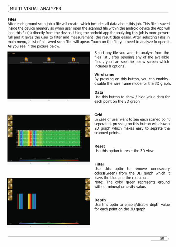
WireframeBy pressing on this button, you can enable/-disable the wire frame mode for the 3D graph.
DataUse this button to show / hide value data for each point on the 3D graph
Gridİn case of user want to see each scaned point seperated, pressing on this button will draw a 2D graph which makes easy to seprate the scanned points.
ResetUse this option to reset the 3D view
FilterUse this optin to remove unnesecery colors(Green) from the 3D graph which it leavs the blue and the red colors.Note: The color green represents ground without mineral or cavity value.
DepthUse this optin to enable/disable depth value for each point on the 3D graph.
MULTI VISUAL ANALYZER
50
FilesAfter each ground scan job a file will create which includes all data about this job. This file is saved inside the device memory so when user open the scanned file within the android device the App will load this file(s) directly from the device. Using the android app for analysing this job is more power-full and it gives the user to filter and measurement the result data easier. After selecting Files in main menu, a list of all saved scan files will apear. Touch on the file you need to analyze fo open it.As you see in the picture below.
Select any file you want to analyze from the files list , after opening any of the avaialble files , you can see the below screen which includes 8 options .
MULTI VISUAL ANALYZER
51
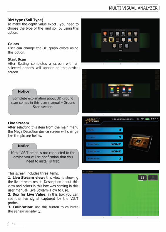
Dirt type (Soil Type)To make the depth value exact , you need to choose the type of the land soil by using this option.
ColorsUser can change the 3D graph colors using this option.
Start ScanAfter Setting completes a screen with all selected options will appear on the device screen.
Live StreamAfter selecting this item from the main menu the Mega Detection device screen will change like the picture below.
This screen includes three items.1. Live Stream view: this view is showing the live stream result. Description about this view and colors in this box was coming in this user manual- Live Stream- How to Use.2. Box for Live Value: in this box you can see the live signal captured by the V.S.T probe.3. Calibration: use this button to calibrate the sensor sensitivity.
Notice
complete explanation about 3D ground scan comes in this user manual – Ground
Scan section.
Notice
If the V.S.T probe is not connected to the device you will se notification that you
need to install is first.
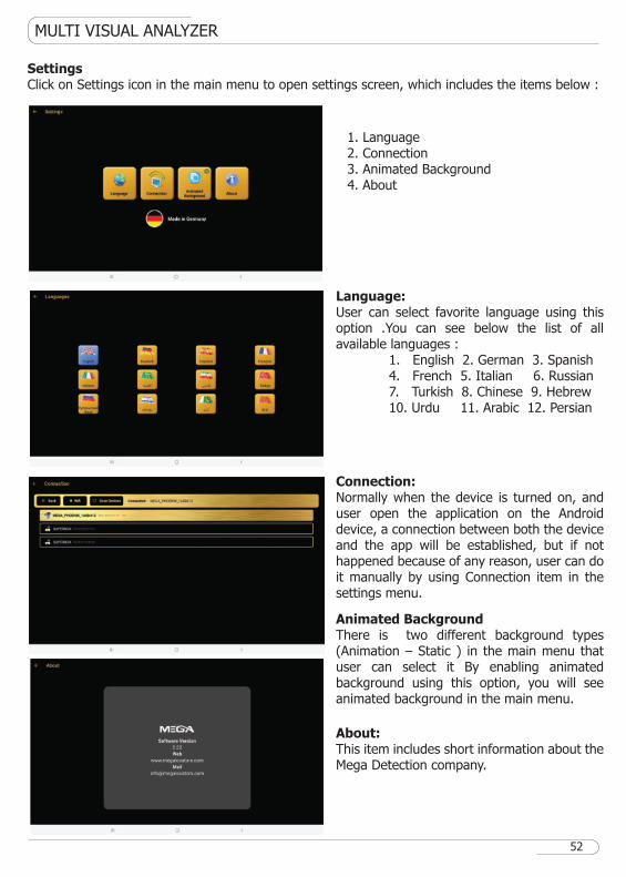
1. Language2. Connection3. Animated Background4. About
MULTI VISUAL ANALYZER
Language:User can select favorite language using this option .You can see below the list of all available languages : 1. English 2. German 3. Spanish 4. French 5. Italian 6. Russian 7. Turkish 8. Chinese 9. Hebrew 10. Urdu 11. Arabic 12. Persian
Connection:Normally when the device is turned on, and user open the application on the Android device, a connection between both the device and the app will be established, but if not happened because of any reason, user can do it manually by using Connection item in the settings menu.
Animated BackgroundThere is two different background types (Animation – Static ) in the main menu that user can select it By enabling animated background using this option, you will see animated background in the main menu.
About:This item includes short information about the Mega Detection company.
SettingsClick on Settings icon in the main menu to open settings screen, which includes the items below :
52
CUSTOMER SERVICES
53
Customer Services
� All devices attached to the device are interchangeable by region and the customer center respon-sible for the service.
� You cannot apply the elements designed for this device with other devices.
� The user can obtain all auxiliary parts through GMI distributors after ensuring compatibility with the device. Sales and maintenance services are only available at GMI accredited centers. GMI is not responsible for the warranty or maintenance of any damage arising out of the use of accessories from other sources.
� You can get all information related to the use of the device and auxiliary parts by visiting the company's website.
The product or service guarantee will not be extended in the following cases:1. If the product has been repaired, modified or changed, unless such repair, modification or change is authorized by MEGA DETECTION2. If the product serial number is deformed or missing.
TECHNICAL SPECIFICATION
54
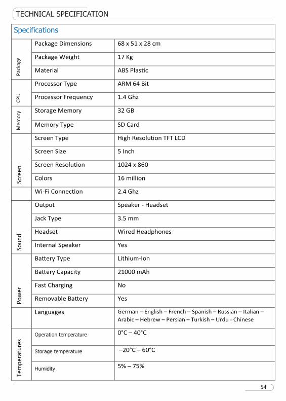
Specifications
Pa
cka
ge
Package Dimensions 68 x 51 x 28 cm
Package Weight 17 Kg
Material ABS Plas�c
CP
U
Processor Type ARM 64 Bit
Processor Frequency 1.4 Ghz
Me
mo
ry Storage Memory 32 GB
Memory Type SD Card
Scr
ee
n
Screen Type High Resolu�on TFT LCD
Screen Size 5 Inch
Screen Resolu�on 1024 x 860
Colors 16 million
Wi-Fi Connec�on 2.4 Ghz
So
un
d
Output Speaker - Headset
Jack Type 3.5 mm
Headset Wired Headphones
Internal Speaker Yes
Po
we
r
Ba�ery Type Lithium-Ion
Ba�ery Capacity 21000 mAh
Fast Charging No
Removable Ba�ery Yes
Languages German – English – French – Spanish – Russian – Italian –
Arabic – Hebrew – Persian – Turkish – Urdu - Chinese
Te
mp
era
ture
s
Operation temperature 0°C – 40°C
Storage temperature –20°C – 60°C
Humidity 5% – 75%
55
56

PIN POINTERLIVE STREAMBIONICIONICMANUAL LRLCTRL LRLAUTO LRLGROUND SCAN