Embed Size (px)
Citation preview
Use of Fault Trees
for
Operations and Systems
1 July 1996
Prepared by:J. Scott WrightSafety Engineer
Chemical and Biological Defense CommandEdgewood Research, Development and Engineering Center
Report Documentation Page Form ApprovedOMB No. 0704-0188
Public reporting burden for the collection of information is estimated to average 1 hour per response, including the time for reviewing instructions, searching existing data sources, gathering andmaintaining the data needed, and completing and reviewing the collection of information. Send comments regarding this burden estimate or any other aspect of this collection of information,including suggestions for reducing this burden, to Washington Headquarters Services, Directorate for Information Operations and Reports, 1215 Jefferson Davis Highway, Suite 1204, ArlingtonVA 22202-4302. Respondents should be aware that notwithstanding any other provision of law, no person shall be subject to a penalty for failing to comply with a collection of information if itdoes not display a currently valid OMB control number.
1. REPORT DATE AUG 1996 2. REPORT TYPE
3. DATES COVERED 00-00-1996 to 00-00-1996
4. TITLE AND SUBTITLE Use of Fault Trees for Operations and Systems
5a. CONTRACT NUMBER
5b. GRANT NUMBER
5c. PROGRAM ELEMENT NUMBER
6. AUTHOR(S) 5d. PROJECT NUMBER
5e. TASK NUMBER
5f. WORK UNIT NUMBER
7. PERFORMING ORGANIZATION NAME(S) AND ADDRESS(ES) Chemical and Biological Defense Command,Edgewood Research,Development and Engineering Center,Aberdeen Proving Ground,MD,21005
8. PERFORMING ORGANIZATIONREPORT NUMBER
9. SPONSORING/MONITORING AGENCY NAME(S) AND ADDRESS(ES) 10. SPONSOR/MONITOR’S ACRONYM(S)
11. SPONSOR/MONITOR’S REPORT NUMBER(S)
12. DISTRIBUTION/AVAILABILITY STATEMENT Approved for public release; distribution unlimited
13. SUPPLEMENTARY NOTES See also ADM000767. Proceedings of the Twenty-Seventh DoD Explosives Safety Seminar Held in LasVegas, NV on 22-26 August 1996.
14. ABSTRACT
15. SUBJECT TERMS
16. SECURITY CLASSIFICATION OF: 17. LIMITATION OF ABSTRACT Same as
Report (SAR)
18. NUMBEROF PAGES
28
19a. NAME OFRESPONSIBLE PERSON
a. REPORT unclassified
b. ABSTRACT unclassified
c. THIS PAGE unclassified
Standard Form 298 (Rev. 8-98) Prescribed by ANSI Std Z39-18
Use of Fault Trees for Operations and Systems
1. INTRODUCTION
A fault tree is a type of hazard analysis used to graphically show all the events andconditions that must occur in order for a specific hazardous event to happen. If the probabilitiesof all the conditioning events are known or can be reasonably approximated, a quantitative valuefor the hazard can be given. The graphical nature of the fault tree allows the reader to see theevents that make up the hazard and concentrate on reducing the probability of major contributors.Fault trees are also especially adept at recognizing single-point failures.
Fault trees have been used in the government for a long time. The pioneer of thetechnique was in the safety analysis of nuclear reactors in the 60's1. Many refinements have beenmade and the standardization of the symbols and process are firmly entrenched. With theincorporation of computer software, fault trees have become much easier to create, no longerrequiring recopying whenever an error is found or an event added. Also, computers haveeliminated the arduous process of calculating the probability of the top event by Boolean algebra.
Currently, fault trees are being used for both operations (movement of ton containers fromCASY to the CTF2) and with systems (XM998 Smoke Grenades3) at ERDEC. The graphicalpresentation of the fault tree makes it effective for presentations and can be easily understood in ashort period of time. This is a great improvement over forcing a person to go through pages ofdocumentation to find the hazards. This type of analysis is important when a specific hazardprobability is desired. The Army’s requirement for safe and arm devices to have a failure rate ofless than one in a million requires a quantitative hazard analysis.
2. FAULT TREE CONSTRUCTION
The process of constructing a fault tree involves three major steps; problem definition,brainstorming, construction. This section describes how the ERDEC Safety Office performs faulttrees using an example of getting to work on time.
The first step is to define the problem and come up with a top event. The top event is thecondition which you are trying to avoid, for instance “Failing to Get to Work on Time”. Thisevent is important because the results will be directly related to the top event. If the top event ispoorly worded or too broadly focused the fault tree may wonder to inconsequential events andwasted time.
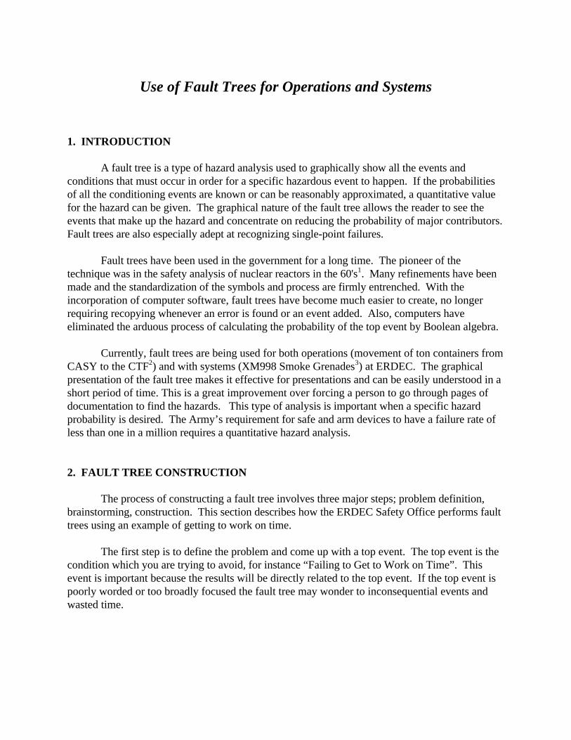
The second step in constructing a fault tree is the brainstorming step. This is the mostimportant and most critical step. At this point you do notneed to use fault tree symbols or construction, focusing onputting thought on paper is the most important thing at thistime. One effective method is to gather a diverse group oftechnicians and managers and brainstorming probablesituations that refer to the top event, for instance, flat tire,stolen car, or crash. You should try to work on the levelunder the top event until it is completely exhausted (figure
1). Trying to work onsecond and third levels earlyimpedes the brainstormingprocess. Once you haveexhausted failures you canfocus on faults and/or conditions that would be required for thefailure to occur, such as other driver cutting you off and yourinability to avoid other car (figure 2). Continue brainstormingeach failure until you get to a point where you have measurableevents or conditions that can be assigned a value.
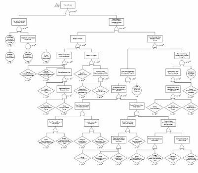
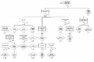
Once you are satisfied that you have completely investigated the problem. You can focuson developing the tree (figure3). The rules for fault trees areclearly established and can befound in many of the referencesat the end of this report. Construction of the tree isfollowed by assigning values tothe events that do not have aconcrete probability orfrequency. Perhaps the mostdifficult probabilities are relatedto human error, human factorstable are available for manycommon tasks9, however manytimes you have to use your bestjudgment.
At this point statistics can be calculated and results are now apparent. For our example,we can expect to be late for work just less than 1 day every year. We can also to expect to getinto an accident once every two years. Fault trees also allow you to change the numbers any timea more accurate statistic is known.
Failing to get to work on
time
-Flat tire -Car stolen-Accident -Run out of Gas-Traffic -OverSleep
Figure 1
Accident- Other driver cuts you off- Bad Weather
- Snow, rain, tornado- Brakes Fail- Not paying attention
- Talking on phone
Figure 2
Figure 3
3. USE IN SYSTEMS
Background
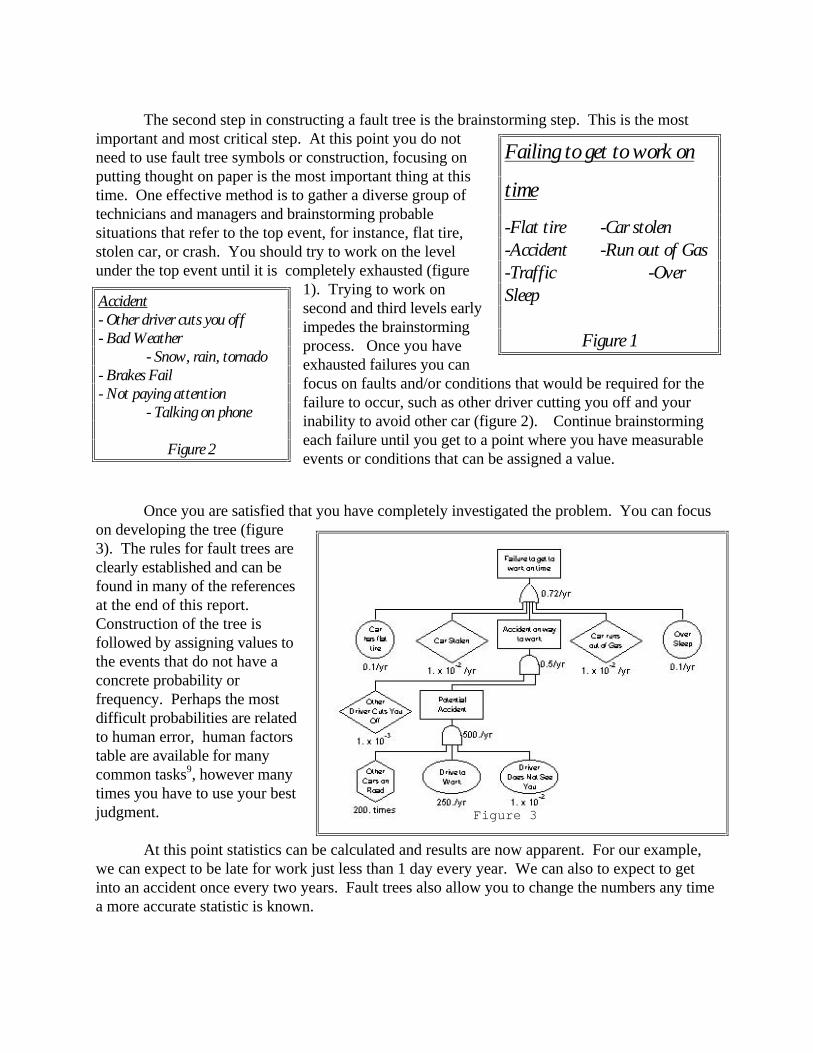
In order to determine the hazardous conditions associated with the safety and armingdevice of the XM998 Smoke Grenade (figure 4) a complete Fault Tree Analysis (FTA) wasperformed. The hazard analysis was conducted to arrive at an estimate of the safety systemfailure rate and to identify any single-point or credible failure modes, as stated in MIL-STD-1316D4. Specifically, the FTA looks for ways the XM998's Safe and Arming Device can fail,allowing the grenade to function unintentionally. The analysis looks at the entire life of the systemand all stages of use: storage, transporting, chambered, loading, handling, and demilitarization. The analysis considers the consequences of the faults and assigns risk to each hazardous scenario. Each scenario may not result in injuries, i.e., if a grenade functions with no one around you havea hazardous situation but no damage.
The XM998 uses a proven basic designand much is known about the safety andreliability of most of its components. Many testshave been conducted on the components of theround to demonstrate the effectiveness of its safeand arming device. These facts are not normallyknown when conducting fault trees; however,there is no reason to ignore them. As a result ofthis, the fault tree may skip hazards that wouldbe mitigated by proven safety features.
The quantitative inputs into the fault treeare products of testing, analogy, and sometimesusing best guess. This is an unavoidable problemwhen dealing with fault trees. In most cases, thisanalysis uses the most conservative numbers in order to give the worst casescenario. When reading the results of the fault tree, you may take any event and say that theprobability of that event occurring is equivalent to the corresponding number.
2. Assumptions
1. Testing performed is representative of the real world.2. Basic human errors occur without any misguiding indicators.3. All drops are considered to be six foot drops.4. In the absence of actual failure probabilities the event was broken into three categories with the corresponding probability.
a. Extremely Improbable (1x10⁻⁹) - Not considered credible.b. Improbable (1x10⁻⁶) - Not likely to happen in the life of the project.
Figure 4
c. Credible (1x10⁻³) - May happen to several rounds in the life of the project.5. The probability for human error is taken to be 1x10⁻³. This number is generally accepted in industry as conservative for common tasks with trained personnel.6. Supporting equipment is in good condition and operated in accordance with standardprocedures. Failure for supporting equipment is 1x10⁻⁶.
Definitions:1. Function - The payload of the grenade is dispersed due to ignition of the central burster.2. Ignition - The propellant in the M195 cartridge case is triggered.3. Fired - The round is ignited and expelled from the tube.
3. Fault Tree Analysis
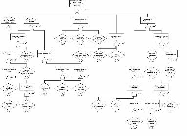
Five states have been developed as possible areas that an unintentional functioning ofa round may occur. The severity of a round functioning in each of these states differs fromcritical to marginal. The probability of an unintentional functioning of a round has beenestimated at 2x10⁻⁸. This is equivalent to saying that one round in every fifty million will havesome part of it fail and function or ignite unintentionally. The probability of safe and armfailure is estimated at 7x10⁻⁹, less than one in every hundred million rounds will have an in-line fuze. The hazard associated with the use of this round is more accurately seen wheneach of the states is analyzed. Each of the scenarios come directly from the fault tree locatedin Appendix A. The five states are as follows:
A. Functioning During Handling/Transporting/Storage of Packaged Rounds
This state includes any condition that occurs while the round is still in its packaging. Thepackaging is subject to testing to determine the severity of many of the scenarios. The tests thatwere conducted include drop, fire, containment, and out-of-line detonator test. Most of thesetests do not give statistical data because of the low number of trials. However, general theoriescan be made. Also, these tests have specific criteria for passing, they may pass a round when ahazardous condition exists, i.e., a drop will not cause the round to function but the escapementsystem may break and move the detonator in-line with the firing pin.
The packaging is designed to prevent the round from functioning and contain much of thehazardous energy. This mitigates many of the hazards associated with inadvertent functioningwhile packaged. In order for a hazardous condition to exist when a round functions, the packageintegrity must be compromised. The scenarios that would test the packaging would include:
Scenario 1: Dropping the container and having a round function. This could only occurto a normal, out-of-line fuze, if one of the following events took place. First, the shock from thedrop causes the burster to detonate. The burster is insensitive and extremely unlikely to functionupon dropping. Second, a drop could cause the detonator to function and if the output of thecharge propagates to the burster the grenade would function. The test for this has beenperformed and a grenade that is fully out-of-line will not allow propagation to the burster.
Risk Assessment: The functioning of a round inside the container should not allowfragments to exit unless the top is open. During handling, the top will not be open under normalcircumstances. The severity would be considered negligible and its 1x10⁻⁹ probability isimprobable. The risk associated would be low.
Scenario 2: Dropping a container with an in-line fuze is another way the round couldfunction. The method for the fuze to become in-line is left in this section as undeveloped. A fulldescription of a fuze becoming in-line is in Section 4. When coupled with a drop an in-line fuzemay allow functioning. The rounds are packaged in such a way that if the package hits on eitherof the two sides, the firing pin may strike an in-line fuze and cause the round to function.
Risk Assessment: Once again the functioning of packaged rounds should not allowfragments to exit unless package integrity is compromised. If rough handling or long storage wasthe reason for the fuze to become in-line, the degraded packaging may allow fragments to escape. The severity is still negligible and a probability of 3x10⁻⁵ is credible. A low risk level isconnected with this scenario.
Scenario 3: A direct or indirect lightning strike could cause the round to function. Alightning strike is always improbable and most of the time the package is under a cone ofprotection. The round should pass the test for lightning strikes as packaged.
Risk Assessment: The hazards associated with a lightning strike would be greater than thefragments possible with functioning grenades. It is improbable that a lightning strike will be seenand cause a round to function, 1x10-15. The additional hazard would be marginal. Thecorresponding risk is low.
Scenario 4: Fire in a storage facility is one of the tests conducted on the packagingcontainer. It is unknown if fragments will escape the packaging during a fire or merely burn. Thefragments associated with a fire is unlikely to cause must more of a problem than the fire itself. Packaging test will be conducted in order to get the proper hazard classification.
Risk Assessment: As with the lightning scenario, the danger to personnel would be moreaffected by the fire than a functioning containerized round. Since the package will contain mostof the fragments the increased severity would be marginal. The probability is improbable andthe risk is low.
Scenario 5: The XM998 is a standard round and may be stored with other types ofmunitions. The functioning of an adjacent munition may produce fragments penetrating thepackaging material. A direct hit to the burster may cause functioning. This scenario would alsoinclude munitions fired at positions storing rounds.
Risk Assessment: The round will not be subjected to the bullet impact test, however nofunctioning would be expected. Fragments escaping the packaging is not considered a credible
hazard. The additional risk would be low since the additional severity is negligible and theprobability is improbable.
Scenario 6: Pyrotechnics have the possibility of spontaneously igniting. If rounds aresubjected to excessive heat, the ignition temperature could be reached. At this temperature theround could function without any other external energy. Moisture from rain or high humidity thatenters the pyrotechnic burster could unstabilize the round and allow functioning with normalhandling.
Risk Assessment: Even in the improbable event that the propellant ignitesspontaneously, the round would not leave the packaging container. Hence, the severity isnegligible and the risk is low.
Scenario 7: A package may be compressed enough to cause functioning. If a vehicle runsover a package, the rounds may function. The energy released from the rounds will probably noteffect a vehicle of the size required to compress the package instead of pushing it. Also, if theround is crushed, its structural integrity is compromised and it probably will not be able to holdthe pressure required for the burster to function properly.
Risk Assessment: The effects of a packaged round functioning under a tank or othermilitary vehicle would be negligible. The likelihood of a container being run over by a vehicle isimprobable hence the risk would be low.
B. Functioning While in the Launcher
Once the round is loaded in the launcher, it is susceptible to faults from the M203 grenadelauncher. This analysis tries to not include faults from the launcher, however, it is assumed that alauncher fault is one in a million. Two different hazards can be associated with a loaded round. First, the round expels from the tube toward an uncleared area. This is particularly hazardous dueto the likelihood of nearby people and equipment. Second, if the round functions inside the barrelof the launcher, in-bore firing. A set of scenarios has been developed for these hazards asfollows:
Scenario 1: Electrical spark hits the propellant causing an ignition in the M195 cartridge. This could be caused from a static buildup of electricity under normal movement and the firing ofbullets. However, since the weapon is bonded to the human carrier, static is unlikely to be aproblem.
Risk Assessment: A spark created with the normal use of the weapon would be unlikelyto hit the exact spot required for the propellant to ignite. This combined with the unlikely sparkgeneration hazard gives a probability considered negligible but the severity is critical due thepossibility of a round functioning in close proximity with its human carrier. The risk is low.
Scenario 2: The propellant could be struck by other than normal means resulting in anearly firing. The striking could be a direct result of dropping the weapon and causing the hammerto strike the round. Other weapon faults could also cause the propellant to be triggered. Theseare all grouped together on the fault tree.
Risk Assessment: Since the weapon is a standard item its safety is given and notconsidered in this report. The round itself does not have to be at fault for this scenario to occur.The probability is remote and the severity is critical . The risk equates to medium. This risk isassociated with the weapon and not the round. The round adds little to this scenario and nochanges can be made to the round to decrease the risk.
Scenario 3: If a round is chambered with an in-line fuze, firing can result in an immediatefunctioning. The pressure associated with propelling the round out of the tube may be sufficientto simulate impact and allow the firing pin to stab initiate the detonator. This would cause theround to function in-bore and the operator would be vulnerable. The description of how a fuzecan be in-line is in Section 4.
Risk Assessment: A round functioning inside the launcher may injure the soldier andsimilar occurrences have resulted in death, a catastrophic hazard. The probability of having anin-line fuze chambered in the round is low, but likely to happen in the lifetime of the system. Theinspection process involves three independent inspections at the factory, prior to assembly, and anX-ray after assembly. Even using the human error rate of failure, 1x10⁻³, the probability isimprobable. The risk is medium.
Scenario 4: If a round is struck by a bullet, fragments, or lightning, it may function. Thepenetration of the round can cause the burster to function. However, the soldier is likely to be ingreater danger from the source of the fault rather than the round functioning.
Risk Assessment: When considering the reasons for the round fault, lightning strikes,bullets, and munition fragments, the severity of the round functioning is negligible. It is alsoimprobable that the round could function under these conditions. The additional risk is low.
C. Functioning During Loading
The loading of rounds is guided by the launcher’s operation manual. Under normalcircumstances, following this operation manual virtually guarantees safe operation. However,abnormal situations or failure to follow the guide could result in premature firing. Two scenarioshave been determined to allow ignition of the round during loading.
Scenario 1: If a spark is generated when the launcher is closed with a loaded round, theprimer may ignite and expel the round from the tube. No spark is normally generated and the sizeof a spark is extremely unlikely to cause the primer to ignite. Heat generated from this spark isalso unlikely to cause a problem.
Risk Assessment: A round functioning on loading poses a critical hazard due to theproximity of personnel and equipment. The probability is improbable and the risk is low.
Scenario 2: If the tube is not cleared before loading the round, a foreign object may hitthe primer on the M195 cartridge case, simulating a hammer strike and launch the round. Thedesign of the round and launcher preclude this from being a plausible scenario.
Risk Assessment: Foreign objects should be cleared from the tube before loading. Even ifthe operator fails to clear the tube properly, the probability of ignition is still improbable. Theseverity is again critical due to the proximity of personnel and equipment. The risk is low.
D. Functioning During Handling
Handling of unpackaged rounds is the most hazardous time for the XM998 grenade. Thesoldier exposes the round to a much wider range of environments. The round is subject toweather, heat, and water all while being positioned in close proximity to the soldier. Twoscenarios are cited for when a soldier is handling the round.
Scenario 1: If the unpackaged round is dropped during loading or anytime during the lifeof the round there is a chance of firing. The round is tested for dropping, however, if the round iscompromised with an in-line fuze due to a previous fault the round may function, Section 4. Ifthe round is dropped on the ogive or base, it can cause the firing pin to strike the detonator.
Risk Assessment: There is a remote chance of a six-foot drop causing the round tofunction, due to the safe and arm device of the round. Injury of the worker would includefragments from the projectile hardware, burning from the disseminated RP, and smoke inhalation;critical severity. The risk is medium.
Scenario 2: Exposing the round to excessive heat and moisture could cause spontaneousfunctioning of the round. If rounds are subjected to excessive heat, the ignition temperature couldbe reached. At this temperature the round could function without any other external energy. Moisture from rain or high humidity that enters the pyrotechnics could unstabilize the round andallow functioning with normal handling.
Risk Assessment: It is an improbable event that the primers or propellants could ignitespontaneously. The severity is critical due to the proximity of the soldier to the grenade. Therisk is low.
E. Functioning During Demilitarization
Demilitarization procedures have been established for the XM998 grenade. Theprocedures call for more than sufficient safety practices for disposal of this grenade. This is stillan inherently dangerous procedure and a spark from static build up on the conveyor or a fault inthe deactivation furnace could allow hazardous energy to escape from engineering controls. Theonly nonstandard procedure is the removal of RP from the round, which is not extremelyhazardous.
Risk Assessment: The demilitarization process was designed for high explosive roundsthat pose a much higher danger. The process limits the severity of a round functioning tomarginal while keeping the probability at remote. The risk is low.
4. In-Line Fuze Analysis
The M550 Escapement Assembly can become in-line from a number of events. The safetydevices on the assembly require most of the faults to be a combination of many failures. Havingan in-line fuze is the driving force behind most of the hazard associated with the use of the round. Any effort reducing the possibility of an in-line fuze increases the safety of the overall grenade.
The only single-point failure is the incorrect assembly of the round in such a way that thedetonator is in-line with the firingpin. Inspection of all rounds isperformed to ensure that this faultdoes not occur. Physically, there isnothing to stop the escapement frombeing assembled with an in-linedetonator except the skill of theworker. The inspection process usesthree independent inspections. Thefirst is at the factory where the M550is fabricated. The second is prior isassembly of the XM998. The third isan X-ray inspection after the round isassembled. The probability of a in-line fuze getting through each
inspection has been expressed as one in a million, 1x10⁻⁶, making the overall failure rate 1x10-18. Since this is a catastrophic failure the associated risk is medium.
If the assembly of the round is performed correctly, a combination of events must occur tohave an in-line detonator. A common fault for all following scenarios is the failure of the setbackpin. The setback pin can fail by either having the pin snap or having the setback spring fail,allowing the pin to fall out of safe.
Breaking of the setback pin is not likely to occur under normal circumstances. It isextremely unlikely that a good pin would break if the round is dropped, no test data was found forthis scenario but it was assumed to be extremely unlikely for a six-foot drop. If the pin hasdeteriorated from water, humidity, or the generation of phosphoric acid from the payload, theprobability of a pin breaking on a drop is greater.
If the setback pin fails, one of the following combinations must occur to allow thedetonator to move freely and become in-line: rotor teeth fail, detent/detent spring fails withpinion failure, or detent fails with verge failure. If the detent fails by itself, the rotor will rotatewith gravity or normal jostling to the armed position.
The rotor teeth provide the locking mechanism for the detent safety system as well as apart of the delay. Failure of the teeth will result in a freely moving detonator if the setback pinfails. The teeth could corrode and break if allowed to rust and deteriorate. Also if incorrectlyinstalled, the teeth may not contact the detent and pinion systems.
Detent failure can occur by failure of either detent pin or detent spring failure. If water orphosphoric acid is allowed in the escapement the spring or detent could corrode and break. Afterlong storage, the spring could fatigue and cause the detent to lose contact with the rotor teeth. The spring or detent could be installed improperly or left out of the assembly all together. Any ofthese failures with a setback pin failure would allow limited movement of the detonator or freemovement with a pinion or verge failure.
The pinion and verge work together to act as the delay mechanism. If one of thesesystems fails, there will be no delay and the grenade will be armed almost immediately after firing. This should not cause a hazardous condition under normal circumstances, but it is one of thesafety devices used in the grenade. If the setback pin and detent fail, pinion or verge failure willallow for free movement of the detonator. The detonator will be in the in-line position wheneverit is rotated in the clockwise direction or when in-line is the lowest potential energy state. Thepinion and verge systems are subject to incorrect assembly, corrosion from water, phosphoricacid, or reaction between differing metals.
5. Results
A. Hazard Analysis
All the hazards associated with faults of the XM998 grenade are low except for threemediums. The first is a fault by the weapon causing a round to be fired prematurely. This is asingle point failure on the part of the weapon, for which the reliability was not researched for thisanalysis. The probability may be lower and the hazard may in fact be low. The second hazard isfor firing a round with an in-line fuze. Again, this is a single-point failure and if a round is loadedwith an in-line fuze, in-bore functioning is probable. The final medium hazard is dropping a round
during out of package handling. This is particularly hazardous if the round is in-line, since out-of-line tests show no propagation to the burster.
There is really no solution to mitigate the medium hazards, when there is a need for asystem that containing sufficient energy to result in catastrophic failure; no probability will resultin a low hazard.
B. Sensitivity Analysis
Since the fault tree process is inherently flawed when using quantitative data, it isimportant to know the upper and lower bounds of risk. While the numbers use the bestknowledge currently known, there is a possibility that future events will change the numbers in apositive or negative manner. This is especially critical when dealing with single-point hazards. Iffuture events result in knowledge that the round is susceptible to a fault at a higher rate thandescribed on the fault tree, that number should be plugged in to see how the overall safety iseffected. For instance, if the assembly of rounds show a high rate of error such that an in-linefuze has a higher possibility of occurring, many of the hazards would probably become high.
6. Conclusions
The XM998 grenade is safe considering its use of explosive and pyrotechnic materials. The safe and arm device mitigates the hazards associated with basic handling and operation. There are very few single-point failures and many of the failures shown on the fault tree are notconsidered credible. Many of the failures cannot be stopped by any safe and arm device and thehazard associated with the fault is greater than the grenade failure, notably fire, lightning, andfragments from other munitions. Since the safe and arm device used for the XM998 has beenused in other systems, any change would increase the hazard by reducing the confidence in itsdesign. Overall, the safe and arm device used for the XM998 grenade is the best available.
4. USE IN OPERATIONS
Background
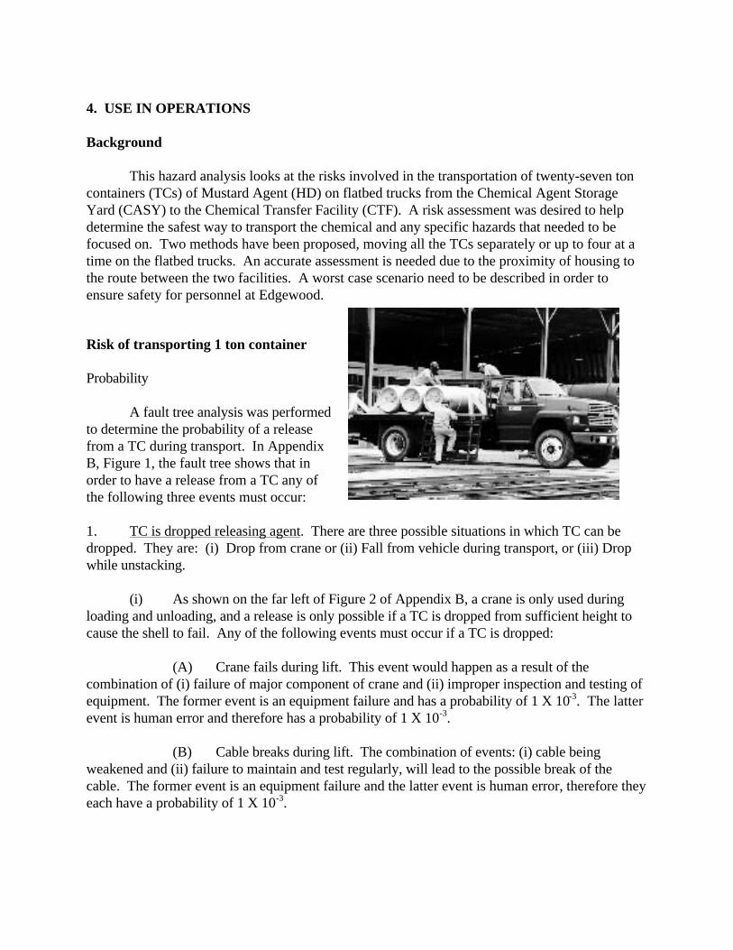
This hazard analysis looks at the risks involved in the transportation of twenty-seven toncontainers (TCs) of Mustard Agent (HD) on flatbed trucks from the Chemical Agent StorageYard (CASY) to the Chemical Transfer Facility (CTF). A risk assessment was desired to helpdetermine the safest way to transport the chemical and any specific hazards that needed to befocused on. Two methods have been proposed, moving all the TCs separately or up to four at atime on the flatbed trucks. An accurate assessment is needed due to the proximity of housing tothe route between the two facilities. A worst case scenario need to be described in order toensure safety for personnel at Edgewood.
Risk of transporting 1 ton container
Probability
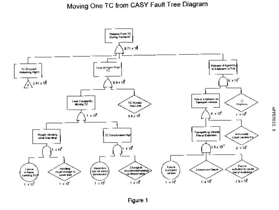
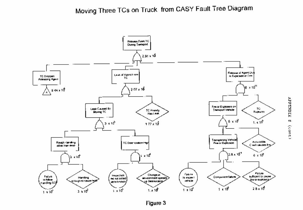
A fault tree analysis was performedto determine the probability of a releasefrom a TC during transport. In AppendixB, Figure 1, the fault tree shows that inorder to have a release from a TC any ofthe following three events must occur:
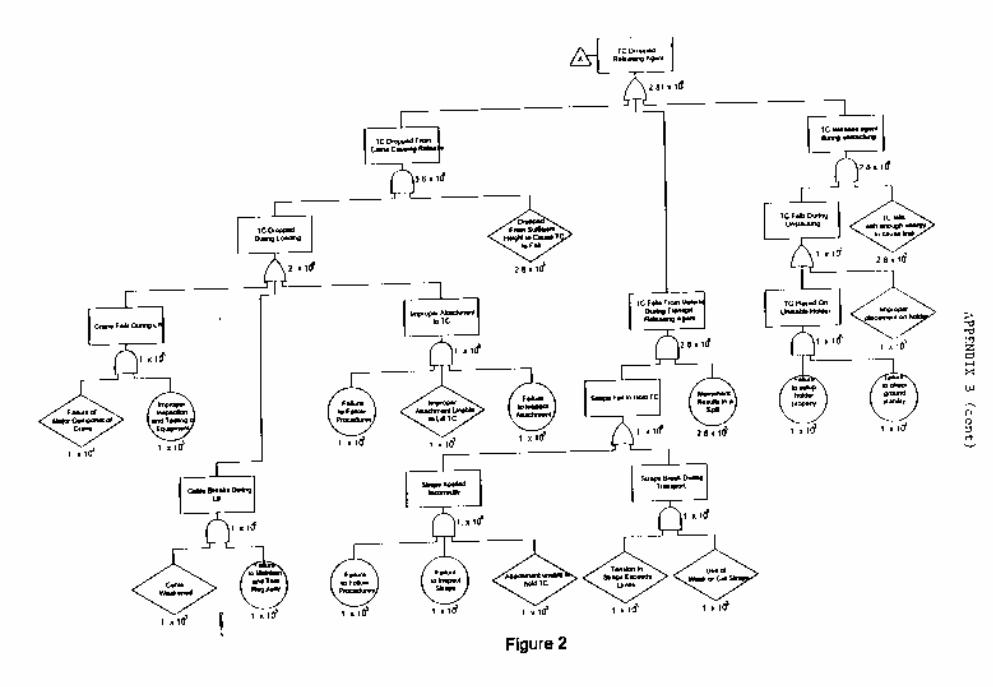
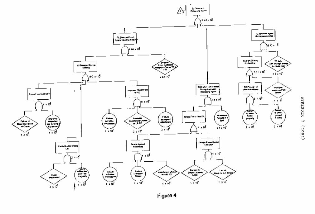
1. TC is dropped releasing agent. There are three possible situations in which TC can bedropped. They are: (i) Drop from crane or (ii) Fall from vehicle during transport, or (iii) Dropwhile unstacking.
(i) As shown on the far left of Figure 2 of Appendix B, a crane is only used duringloading and unloading, and a release is only possible if a TC is dropped from sufficient height tocause the shell to fail. Any of the following events must occur if a TC is dropped:
(A) Crane fails during lift. This event would happen as a result of thecombination of (i) failure of major component of crane and (ii) improper inspection and testing ofequipment. The former event is an equipment failure and has a probability of 1 X 10⁻³. The latterevent is human error and therefore has a probability of 1 X 10⁻³.
(B) Cable breaks during lift. The combination of events: (i) cable beingweakened and (ii) failure to maintain and test regularly, will lead to the possible break of thecable. The former event is an equipment failure and the latter event is human error, therefore theyeach have a probability of 1 X 10⁻³.
(C) Improper attachment to TC. This failure is a combination of three possibleevents: (i) Failure to follow procedures (ii) Improper attachment and (iii) Failure to inspectattachment. All three of these are human errors and therefore have a probability of 1 X 10⁻³.
(ii) The middle of the fault tree in Figure 2 of Appendix B showed the event in which aTC falls from a vehicle during transport. As illustrated, the fall is only possible if 1) Straps fail tohold TC and 2) Speed is high enough for movement of TC. There are two ways in which strapscan fail to hold TC. They are:
(A) Straps are applied incorrectly. This is a combination of failure to followprocedures, failure to inspect straps and attachment unable to hold TC. These are human errorsand an equipment failure and therefore have a probability of 1 X 10⁻³.
(B) Straps break during transport. Straps are broken as a result from eithertension on straps exceeds limits or weak or cut straps are used. One is an equipment failure andone is a human error and therefore have a probability of 1 X 10⁻³.
(iii) Referring to the far right of the fault tree in Figure 2 of Appendix B, a TC releasesagent during unstacking only if “TC falls during Unstacking” and “the fall must have sufficientimpact energy to cause breakage”. Fall of TC during Unstacking can result from two conditions:
(A) TC is placed on unstable holder. As illustrated in the figure, such unstablecondition is caused by failure to setup the holder properly or failure to check ground stability. These are human errors and have a probability of 1 X 10⁻³.
(B) Improper placement of holder by workers. This is a human error and has aprobability of 1 X 10⁻³.
2. Leak of Agent from TC. As shown in Figure 1, Appendix B, a leak can be caused by themove of TC or if a leak already exists (Probability: 5.9 X 10⁻⁶)5. A leak caused by moving TC canoccur if (i) handling is rough or (ii) deterioration is high.
(i) In order for a TC to leak while being handled, both of the following events mustoccur “Failure to follow the SOP” and “Sufficient roughness to cause a leak”. These are a humanerror and an equipment failure and therefore have a probability of 1 X 10⁻³.
(ii) High deterioration of TC can be a combination of change in environment whichwould speed up the process and failure to detect through inspection. These are a human error andan equipment failure and therefore have a probability of 1 X 10 -3.
3. Release of agent due to explosion or fire. From Figure 1 of Appendix B, one of thefollowing event must occur to result in an explosion or fire: 1) Automobile crash (probability: 6 X10⁻⁵, or 2) Transporting vehicle catches on fire or explodes. Fire or explosion of transport vehiclecan happen if a combination of the following three events occur: “Failure to inspect the vehicle”
(Human error probability: 1 X 10⁻³), “Component failure” (Equipment failure probability: 1 X 10-
3), and “Failure sufficient to cause fire or explosion” (probability: 2.8 X 10⁻⁴ )5.
4. Release of agent due to mechanical forces generated in a vehicle accident (not shown infault tree). Two events must occur in order for this to happen: 1) Truck is in an accident (1 X 10-
4), and 2) Leak occurs due to the accident (1.2 X 10⁻⁴)5.
The probability of each of the 4 main subevents is therefore:
1. TC Dropped Releasing Agent 2.81 X 10⁻⁶
2. Leak of Agent From TC 6.90 X 10⁻⁶
3. Release of Agent Due to Fire or Explosion 6.00 X 10⁻¹¹
4. Release of Agent Due to Mechanical Forces/Accident 1.20 X 10⁻¹¹
NOTE: Since the probability of last event was not credible, it was left out of the faulttree. The third event was depicted in the fault tree because if this event were credible, itwould provide the longest downwind hazard (result of mustard on fire).
The overall calculated probability of having a release of agent from a TC during transport is 9.71X 10⁻⁶' as shown in Figure 1 of Appendix B. From Table 4 of Appendix C, this probability iscategorized as E, improbable6.
Severity. The severity was based on the credible subevent which involved the largestrelease of agent. This is assumed to be a rupture of the ton container spilling the entire contentsof the TC (1700 lb.). Using the assumptions above and this amount of agent, the D2PCdownwind prediction program7 calculated a 1% lethality distance of 31 meters and a No effectsdistance of 541 meters. This presents a danger to personnel on post but not off post (Unless therelease occurs in Bush River Storage Area. The No effects downwind arc extends approximately400 feet into the Bush River.). Therefore, because of the on-post hazard, the severity of thisconsequence is categorized as I, catastrophic6.
Risk. The risk associated with transporting 1 ton container from CASY to the CTF is I-E, catastrophic-improbable. According to military guidance, the risk level is MEDIUM.
Risk of transporting 3 ton containers on a single truck.
Probability . Using the same fault tree and changing probabilities of bottom events basedon 3 ton containers instead of 1 TC, the probability of a release from a TC during the transport of3 TCs on a single truck was calculated. Though investigation it was determined that the only
probability that would change from the 1 TC move is a slightly higher risk of mechanical failure. However, this increase is not enough to change the improbably to remote, thus not significantlyeffecting the risk.
Severity. The severity was based on the credible subevent which involved the largestrelease of agent. This agent is a rupture of the ton container spilling the entire contents of the TC(1700 lb.). However, since this task is performed one at a time, the severity does not change.
Risk. The risk associated with transporting 3 ton containers from CASY to the CTF is I-E, catastrophic-improbable. According to Figure 2 of Appendix C (ref. 3e), the risk level isMEDIUM.
Risk of transporting 9 ton containers on 3 trucks (3 TCs per truck).
Probability . Since we have determined the probability of release of 1 ton container froma single truck of 3 TCs, the probability of release of 1 TC from 3 trucks with 3 TCs is simply 3times the former probability (2.91 X 10⁻⁵), or 8.73 X 10⁻⁵. This probability is categorized as E,improbable.8
Severity. The severity does not change since a rupture of the ton container that releasesis still credible and a fire is not credible. Therefore, the severity of this consequence is based onthe same downwind release and is categorized as I, catastrophic6.
Risk. The risk associated with transporting 9 ton containers from CASY to the CTF is I-E, catastrophic-improbable. According to Figure 2 of Appendix C (ref. 3e), the risk level isMEDIUM.
CONCLUSION .
All of the scenarios examined have the same chemical risk, MEDIUM. The scenario ofhauling 9 ton containers at once is the most timely while maintaining the lowest possible risk.
RECOMMENDATION .
Move 27 ton containers in three convoys consisting of 9 TCs on 3 trucks (3 TCs pertruck) from the CASY to the CTF for sampling. (Chemical risk: MEDIUM)
5. CONCLUSION
The use of fault trees has added to the effectiveness of the Edgewood Safety Office. Faulttrees have proved themselves as a valuable tool in minimizing risk and extremely useful inconveying the risk to both workers and management. The ease of use and the effectiveness ofthe graphical presentation makes fault trees better than most every other hazard analysis.
6. REFERENCES
1. Fault Tree Handbook, NUREG-0492, Roberts, N. H., et al., Systems and ReliabilityResearch Office of Nuclear Regulatory Research, 1981
2. Risk Assessment for Transferring Ton Containers, Franchere, J. E., et al., 11 April 95.
3. Fault Tree Analysis of XM998 Smoke Grenade, Wright, J. S., 16 April 96.
4. Mil-Std-1316D, Safety Criteria for Fuze Design, 9 April 91.
5. Risk Analysis of the Onsite Disposal of Chemical Munitions, Chemical StockpileDisposal Program, Aug 87.
6. Mil-Std 882C
7. D2PC, Personal Computer Program for Chemical Hazard Prediction, C. GlenvilWhitacre, Joseph H. Griner, Michael M. Myirski and Dale W. Sloop, January 1987.
8. System Safety Management Plan for the Chemical Stockpile Disposal Program, Apr91.
9. NUREG-CRX-1278, Handbook of Human Reliability Analysis, Emphasis on NuclearPower Plant Applications.
10. AR 385-16, System Safety Engineering and Management
11. ERDEC System Safety Engineering and Management Plan, 28 Apr 93.
12. Chemistry of Pyrotechnics, Conklin, J. A., Marcel Dekker, Inc., 1985.
13. TB 700-2, Department of Defense Explosives Hazard Classification Procedures
14. FaultrEASE - A Graphics Tool for Fault Trees, A. D. Little, 1993.
15. A Mathematical Model for a Quantitative Risk Matrix, Proper, K. W., US ArmyDefense Ammunition Center and School.
16. Advanced Concepts in Fault Tree Analysis, Haasl, D. F., System Safety Symposium,1965.
17. Guidelines for Chemical Process Quantitative Risk Analysis, Center for ChemicalProcess Safety of the American Institute of Chemical Engineers, 1989.
18. Chemical Stockpile Disposal Program Final Programmatic Environmental ImpactStatement, Jan 88.
19. Manual Two of the Chemical Hazards Response Information System (CHRIS), 11 Sep78.
Appendicies
A. Fault Tree for XM998 Smoke Grenade
B. Fault Tree for Transporting Ton Container
C. Risk Assessment Codes
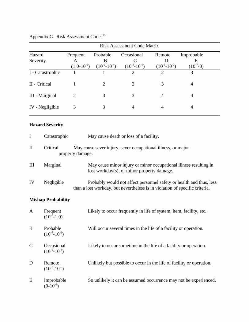
Appendix C. Risk Assessment Codes15
Risk Assessment Code Matrix
Hazard Frequent Probable Occasional Remote ImprobableSeverity A B C D E (1.0-10-2) (10-2-10-4) (10-4-10-6) (10-6-10-7) (10-7-0)I - Catastrophic 1 1 2 2 3
II - Critical 1 2 2 3 4
III - Marginal 2 3 3 4 4
IV - Negligible 3 3 4 4 4
Hazard Severity
I Catastrophic May cause death or loss of a facility.
II Critical May cause sever injury, sever occupational illness, or major property damage.
III Marginal May cause minor injury or minor occupational illness resulting in lost workday(s), or minor property damage.
IV Negligible Probably would not affect personnel safety or health and thus, less than a lost workday, but nevertheless is in violation of specific criteria.
Mishap Probability
A Frequent Likely to occur frequently in life of system, item, facility, etc.(10-2-1.0)
B Probable Will occur several times in the life of a facility or operation.(10-4-10-2)
C Occasional Likely to occur sometime in the life of a facility or operation.(10-6-10-4)
D Remote Unlikely but possible to occur in the life of facility or operation.(10-7-10-6)
E Improbable So unlikely it can be assumed occurrence may not be experienced.(0-10-7)
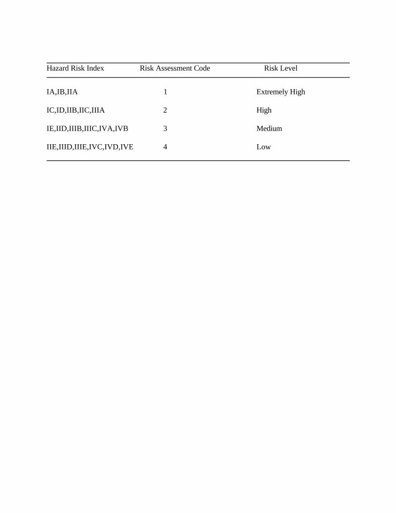
Hazard Risk Index Risk Assessment Code Risk Level
IA,IB,IIA 1 Extremely High
IC,ID,IIB,IIC,IIIA 2 High
IE,IID,IIIB,IIIC,IVA,IVB 3 Medium
IIE,IIID,IIIE,IVC,IVD,IVE 4 Low


![Modeling and Analyzing Faults to Improve Election Process ... · fault trees for intrusion detection systems [23], Zhang et al. use fault trees for vulnerability evaluation [54],](https://img.pdfslide.us/doc/110x75/5dd0b87cd6be591ccb625e1d/modeling-and-analyzing-faults-to-improve-election-process-fault-trees-for-intrusion.jpg)