Embed Size (px)
Citation preview

67$1'$5'63(&,),&$7,216)25�&216758&7,21�2)52$'6�$1'�%5,'*(621�)('(5$/�+,*+:$<352-(&76
FP-961996
8�6��'HSDUWPHQW ��)HGHUDORI�7UDQVSRUWDWLRQ ��/DQGV�+LJKZD\V)HGHUDO�+LJKZD\ �“Commitment to Excellence”
$GPLQLVWUDWLRQ
i
Standard SpecificationsFor Construction of
Roads and Bridges onFederal Highway Projects
FP-961996
U.S. DEPARTMENTOF TRANSPORTATION
Federal HighwayAdministration
For sale by the Superintendent of DocumentsU.S. Government Printing Office
Washington D.C. 20402
iii
PREFACE
These Standard Specifications for the Construction of Roads andBridges on Federal Highway Projects are issued primarily for con-structing roads and bridges on Federal Highway projects under thedirect administration of the Federal Highway Administration. Thesespecifications are cited as "FP-96" indicating Standard Specificationsissued in 1996.
When designated in a contract, the FP-96 becomes part of the con-tract and binding upon all parties to the contract. All constructioncontracts of the Federal Highway Administration are also governedby the following regulations.
Federal Acquisition Regulation (FAR), Title 48, Code ofFederal Regulations, Chapter 1.Transportation Acquisition Regulation (TAR), Title 48, Codeof Federal Regulations, Chapter 12.
The FAR and TAR regulations are not included in the FP-96. How-ever, some FAR and TAR clauses are supplemented in the FP-96.A complete copy of the FAR is available from the Superintendent ofDocuments, Congressional Sales Office, U.S. Government PrintingOffice, Washington, DC 20402.
The International System of Units (SI) is used in the FP-96 as re-quired by Public Law 100-418 (1988 Omnibus Trade and Competi-tiveness Act) and Executive Order 12770 (Metric Usage in FederalGovernment Programs).
iv
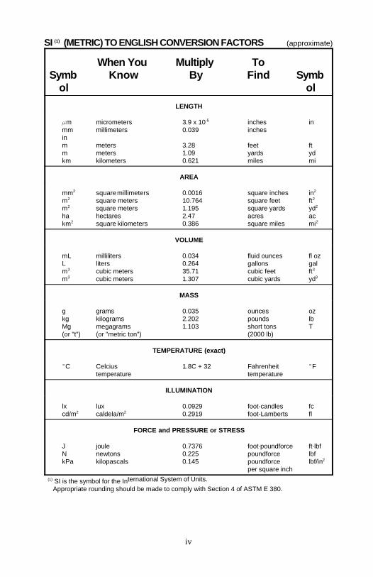
SI (METRIC) TO ENGLISH CONVERSION FACTORS (approximate)(1)
Symb Know By Find Symbol ol
When You Multiply To
LENGTH
m micrometers 3.9 x 10 inches in-5
mm millimeters 0.039 inchesinm meters 3.28 feet ftm meters 1.09 yards ydkm kilometers 0.621 miles mi
AREA
mm square millimeters 0.0016 square inches in2 2
m square meters 10.764 square feet ft2 2
m square meters 1.195 square yards yd2 2
ha hectares 2.47 acres ackm square kilometers 0.386 square miles mi2 2
VOLUME
mL milliliters 0.034 fluid ounces fl ozL liters 0.264 gallons galm cubic meters 35.71 cubic feet ft3 3
m cubic meters 1.307 cubic yards yd3 3
MASS
g grams 0.035 ounces ozkg kilograms 2.202 pounds lbMg megagrams 1.103 short tons T(or "t") (or "metric ton") (2000 lb)
TEMPERATURE (exact)
C Celcius 1.8C + 32 Fahrenheit Ftemperature temperature
ILLUMINATION
lx lux 0.0929 foot-candles fccd/m caldela/m 0.2919 foot-Lamberts fl2 2
FORCE and PRESSURE or STRESS
J joule 0.7376 foot·poundforce ft·lbfN newtons 0.225 poundforce lbfkPa kilopascals 0.145 poundforce lbf/in 2
per square inchternational System of Units. SI is the symbol for the In(1)
Appropriate rounding should be made to comply with Section 4 of ASTM E 380.
v
TABLE OF CONTENTS
Page
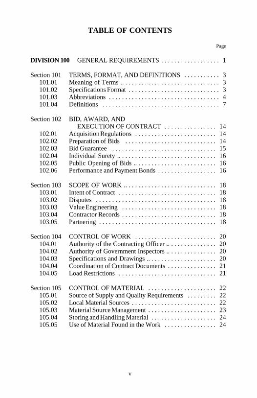
DIVISION 100 GENERAL REQUIREMENTS . . . . . . . . . . . . . . . . . . 1
Section 101 TERMS, FORMAT, AND DEFINITIONS . . . . . . . . . . . 3101.01 Meaning of Terms .. . . . . . . . . . . . . . . . . . . . . . . . . . . . . . 3101.02 Specifications Format . . . . . . . . . . . . . . . . . . . . . . . . . . . . 3101.03 Abbreviations . . . . . . . . . . . . . . . . . . . . . . . . . . . . . . . . . . 4101.04 Definitions . . . . . . . . . . . . . . . . . . . . . . . . . . . . . . . . . . . . 7
Section 102 BID, AWARD, ANDEXECUTION OF CONTRACT . . . . . . . . . . . . . . . . 14
102.01 Acquisition Regulations . . . . . . . . . . . . . . . . . . . . . . . . . 14102.02 Preparation of Bids . . . . . . . . . . . . . . . . . . . . . . . . . . . . 14102.03 Bid Guarantee . . . . . . . . . . . . . . . . . . . . . . . . . . . . . . . . 15102.04 Individual Surety .. . . . . . . . . . . . . . . . . . . . . . . . . . . . . . 16102.05 Public Opening of Bids .. . . . . . . . . . . . . . . . . . . . . . . . . 16102.06 Performance and Payment Bonds . . . . . . . . . . . . . . . . . . 16
Section 103 SCOPE OF WORK .. . . . . . . . . . . . . . . . . . . . . . . . . . . . 18103.01 Intent of Contract . . . . . . . . . . . . . . . . . . . . . . . . . . . . . . 18103.02 Disputes . . . . . . . . . . . . . . . . . . . . . . . . . . . . . . . . . . . . . 18103.03 Value Engineering . . . . . . . . . . . . . . . . . . . . . . . . . . . . . 18103.04 Contractor Records . . . . . . . . . . . . . . . . . . . . . . . . . . . . . 18103.05 Partnering . . . . . . . . . . . . . . . . . . . . . . . . . . . . . . . . . . . . 18
Section 104 CONTROL OF WORK . . . . . . . . . . . . . . . . . . . . . . . . . 20104.01 Authority of the Contracting Officer .. . . . . . . . . . . . . . . 20104.02 Authority of Government Inspectors .. . . . . . . . . . . . . . . 20104.03 Specifications and Drawings .. . . . . . . . . . . . . . . . . . . . . 20104.04 Coordination of Contract Documents . . . . . . . . . . . . . . . 21104.05 Load Restrictions . . . . . . . . . . . . . . . . . . . . . . . . . . . . . . 21
Section 105 CONTROL OF MATERIAL . . . . . . . . . . . . . . . . . . . . . 22105.01 Source of Supply and Quality Requirements . . . . . . . . . 22105.02 Local Material Sources . . . . . . . . . . . . . . . . . . . . . . . . . . 22105.03 Material Source Management . . . . . . . . . . . . . . . . . . . . . 23105.04 Storing and Handling Material . . . . . . . . . . . . . . . . . . . . 24105.05 Use of Material Found in the Work . . . . . . . . . . . . . . . . 24
vi
Page
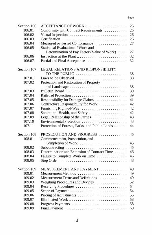
Section 106 ACCEPTANCE OF WORK . . . . . . . . . . . . . . . . . . . . . . 25106.01 Conformity with Contract Requirements . . . . . . . . . . . . 25106.02 Visual Inspection . . . . . . . . . . . . . . . . . . . . . . . . . . . . . . 26106.03 Certification . . . . . . . . . . . . . . . . . . . . . . . . . . . . . . . . . . 26106.04 Measured or Tested Conformance . . . . . . . . . . . . . . . . . 27106.05 Statistical Evaluation of Work and
Determination of Pay Factor (Value of Work) . . . . . 27106.06 Inspection at the Plant .. . . . . . . . . . . . . . . . . . . . . . . . . . 32106.07 Partial and Final Acceptance . . . . . . . . . . . . . . . . . . . . . 32
Section 107 LEGAL RELATIONS AND RESPONSIBILITYTO THE PUBLIC . . . . . . . . . . . . . . . . . . . . . . . . . . . 38
107.01 Laws to be Observed .. . . . . . . . . . . . . . . . . . . . . . . . . . . 38107.02 Protection and Restoration of Property
and Landscape . . . . . . . . . . . . . . . . . . . . . . . . . . . . . . 38107.03 Bulletin Board .. . . . . . . . . . . . . . . . . . . . . . . . . . . . . . . . 39107.04 Railroad Protection . . . . . . . . . . . . . . . . . . . . . . . . . . . . . 39107.05 Responsibility for Damage Claims . . . . . . . . . . . . . . . . . 41107.06 Contractor's Responsibility for Work . . . . . . . . . . . . . . . 42107.07 Furnishing Right-of-Way . . . . . . . . . . . . . . . . . . . . . . . . 42107.08 Sanitation, Health, and Safety .. . . . . . . . . . . . . . . . . . . . 42107.09 Legal Relationship of the Parties . . . . . . . . . . . . . . . . . . 43107.10 Environmental Protection . . . . . . . . . . . . . . . . . . . . . . . . 43107.11 Protection of Forests, Parks, and Public Lands .. . . . . . . 44
Section 108 PROSECUTION AND PROGRESS . . . . . . . . . . . . . . . 45108.01 Commencement, Prosecution, and
Completion of Work . . . . . . . . . . . . . . . . . . . . . . . . . 45108.02 Subcontracting . . . . . . . . . . . . . . . . . . . . . . . . . . . . . . . . 45108.03 Determination and Extension of Contract Time . . . . . . . 46108.04 Failure to Complete Work on Time . . . . . . . . . . . . . . . . 46108.05 Stop Order . . . . . . . . . . . . . . . . . . . . . . . . . . . . . . . . . . . 48
Section 109 MEASUREMENT AND PAYMENT . . . . . . . . . . . . . . 49109.01 Measurement Methods . . . . . . . . . . . . . . . . . . . . . . . . . . 49109.02 Measurement Terms and Definitions . . . . . . . . . . . . . . . 49109.03 Weighing Procedures and Devices . . . . . . . . . . . . . . . . . 52
109.04 Receiving Procedures . . . . . . . . . . . . . . . . . . . . . . . . . . . 54109.05 Scope of Payment . . . . . . . . . . . . . . . . . . . . . . . . . . . . . . 54109.06 Pricing of Adjustments . . . . . . . . . . . . . . . . . . . . . . . . . . 55109.07 Eliminated Work .. . . . . . . . . . . . . . . . . . . . . . . . . . . . . . 58109.08 Progress Payments . . . . . . . . . . . . . . . . . . . . . . . . . . . . . 58109.09 Final Payment . . . . . . . . . . . . . . . . . . . . . . . . . . . . . . . . . 60
vii
Page
DIVISION 150 PROJECT REQUIREMENTS .. . . . . . . . . . . . . . . . . 63
Section 151 Mobilization . . . . . . . . . . . . . . . . . . . . . . . . . . . . . . . . . . 64152 Construction Survey and Staking . . . . . . . . . . . . . . . . . . 66153 Contractor Quality Control . . . . . . . . . . . . . . . . . . . . . . . 73154 Contractor Sampling and Testing . . . . . . . . . . . . . . . . . . 77155 Schedules for Construction Contracts . . . . . . . . . . . . . . . 79156 Public Traffic . . . . . . . . . . . . . . . . . . . . . . . . . . . . . . . . . 84157 Soil Erosion Control . . . . . . . . . . . . . . . . . . . . . . . . . . . . 88158 Watering for Dust Control . . . . . . . . . . . . . . . . . . . . . . . 95
DIVISION 200 EARTHWORK . . . . . . . . . . . . . . . . . . . . . . . . . . . . . 97
Section 201 Clearing and Grubbing . . . . . . . . . . . . . . . . . . . . . . . . . . 98202 Additional Clearing and Grubbing . . . . . . . . . . . . . . . . 101203 Removal of Structures and Obstructions .. . . . . . . . . . . 103204 Excavation and Embankment . . . . . . . . . . . . . . . . . . . . 106205 Rock Blasting . . . . . . . . . . . . . . . . . . . . . . . . . . . . . . . . 120206 Reserved207 Earthwork Geotextiles . . . . . . . . . . . . . . . . . . . . . . . . . 126208 Structure Excavation and Backfill for
Selected Major Structures . . . . . . . . . . . . . . . . . 129209 Structure Excavation and Backfill . . . . . . . . . . . . . . . . 136210 Permeable Backfill . . . . . . . . . . . . . . . . . . . . . . . . . . . . 142211 Roadway Obliteration . . . . . . . . . . . . . . . . . . . . . . . . . . 145212 Linear Grading . . . . . . . . . . . . . . . . . . . . . . . . . . . . . . . 147213 Subgrade Stabilization . . . . . . . . . . . . . . . . . . . . . . . . . 149
DIVISION 250 STRUCTURAL EMBANKMENTS . . . . . . . . . . . . 155
Section 251 Riprap . . . . . . . . . . . . . . . . . . . . . . . . . . . . . . . . . . . . . . 156252 Special Rock Embankment and Rock Buttress . . . . . . . 160253 Gabions and Revet Mattresses . . . . . . . . . . . . . . . . . . . 162254 Crib Walls . . . . . . . . . . . . . . . . . . . . . . . . . . . . . . . . . . . 165255 Mechanically Stabilized Earth Walls . . . . . . . . . . . . . . 168256 Permanent Ground Anchors . . . . . . . . . . . . . . . . . . . . . 172257 Alternate Retaining Walls .. . . . . . . . . . . . . . . . . . . . . . 182258 Reinforced Concrete Retaining Walls .. . . . . . . . . . . . . 187
viii
Page
DIVISION 300 AGGREGATE COURSES . . . . . . . . . . . . . . . . . . . 191
Section 301 Untreated Aggregate Courses . . . . . . . . . . . . . . . . . . . . 192302 Treated Aggregate Courses .. . . . . . . . . . . . . . . . . . . . . 197303 Road Reconditioning . . . . . . . . . . . . . . . . . . . . . . . . . . 204304 Aggregate Stabilization .. . . . . . . . . . . . . . . . . . . . . . . . 208305 Aggregate-Topsoil Course . . . . . . . . . . . . . . . . . . . . . . 213306 Dust Palliative .. . . . . . . . . . . . . . . . . . . . . . . . . . . . . . . 216307 Stockpiled Aggregates . . . . . . . . . . . . . . . . . . . . . . . . . 219308 Minor Crushed Aggregate .. . . . . . . . . . . . . . . . . . . . . . 222309 Emulsified Asphalt Treated Base Course . . . . . . . . . . . 226
DIVISION 400 ASPHALT PAVEMENTS AND
SURFACE TREATMENTS . . . . . . . . . . . . . . . 231
Section 401 Hot Asphalt Concrete Pavement . . . . . . . . . . . . . . . . . . 232402 Minor Hot Asphalt Concrete .. . . . . . . . . . . . . . . . . . . . 251403 Hot Recycled Asphalt Concrete Pavement . . . . . . . . . . 254404 Open-Graded Asphalt Friction Course . . . . . . . . . . . . . 260405 Hot Asphalt Treated Base Course .. . . . . . . . . . . . . . . . 264406 Dense-Graded Emulsified Asphalt Pavement . . . . . . . . 268407 Open-Graded Emulsified Asphalt Pavement . . . . . . . . 274408 Cold Recycled Asphalt Base Course . . . . . . . . . . . . . . 281409 Asphalt Surface Treatment . . . . . . . . . . . . . . . . . . . . . . 286410 Slurry Seal . . . . . . . . . . . . . . . . . . . . . . . . . . . . . . . . . . 295411 Asphalt Prime Coat . . . . . . . . . . . . . . . . . . . . . . . . . . . . 300412 Asphalt Tack Coat . . . . . . . . . . . . . . . . . . . . . . . . . . . . 303413 Asphalt Pavement Milling . . . . . . . . . . . . . . . . . . . . . . 305414 Asphalt Pavement Crack and Joint Sealing .. . . . . . . . . 307415 Paving Geotextiles . . . . . . . . . . . . . . . . . . . . . . . . . . . . 311416 Continuous Cold Recycled Asphalt Base Course . . . . . 314417 Minor Cold Asphalt Mix .. . . . . . . . . . . . . . . . . . . . . . . 321
DIVISION 500 PORTLAND CEMENT CONCRETE PAVEMENT . . . . . . . . . . . . . . . . . . . . . . . . . . . 323
Section 501 Portland Cement Concrete Pavement . . . . . . . . . . . . . . 324502 Portland Cement Concrete Pavement Restoration . . . . 340
ix
Page
DIVISION 550 BRIDGE CONSTRUCTION .. . . . . . . . . . . . . . . . . 353
Section 551 Driven Piles . . . . . . . . . . . . . . . . . . . . . . . . . . . . . . . . . 354552 Structural Concrete . . . . . . . . . . . . . . . . . . . . . . . . . . . . 372553 Prestressed Concrete . . . . . . . . . . . . . . . . . . . . . . . . . . . 404554 Reinforcing Steel . . . . . . . . . . . . . . . . . . . . . . . . . . . . . 420555 Steel Structures . . . . . . . . . . . . . . . . . . . . . . . . . . . . . . . 425556 Bridge Railing .. . . . . . . . . . . . . . . . . . . . . . . . . . . . . . . 453557 Timber Structures . . . . . . . . . . . . . . . . . . . . . . . . . . . . . 457558 Dampproofing .. . . . . . . . . . . . . . . . . . . . . . . . . . . . . . . 463559 Waterproofing .. . . . . . . . . . . . . . . . . . . . . . . . . . . . . . . 465560 Water Stops . . . . . . . . . . . . . . . . . . . . . . . . . . . . . . . . . 469561 Structural Concrete Bonding .. . . . . . . . . . . . . . . . . . . . 471562 Forms and Falsework . . . . . . . . . . . . . . . . . . . . . . . . . . 476563 Painting . . . . . . . . . . . . . . . . . . . . . . . . . . . . . . . . . . . . . 492564 Bearing Devices . . . . . . . . . . . . . . . . . . . . . . . . . . . . . . 502565 Drilled Shafts . . . . . . . . . . . . . . . . . . . . . . . . . . . . . . . . 508
DIVISION 600 INCIDENTAL CONSTRUCTION . . . . . . . . . . . . . 519
Section 601 Minor Concrete Structures . . . . . . . . . . . . . . . . . . . . . . 520602 Culverts and Drains . . . . . . . . . . . . . . . . . . . . . . . . . . . 524603 Structural Plate Structures . . . . . . . . . . . . . . . . . . . . . . 528604 Manholes, Inlets, and Catch Basins . . . . . . . . . . . . . . . 531605 Underdrains, Sheet Drains, and
Pavement Edge Drains . . . . . . . . . . . . . . . . . . . . 535606 Corrugated Metal Spillways . . . . . . . . . . . . . . . . . . . . . 541607 Cleaning, Reconditioning, and Repairing
Existing Drainage Structures . . . . . . . . . . . . . . . 543608 Paved Waterways . . . . . . . . . . . . . . . . . . . . . . . . . . . . . 545609 Curb and Gutter . . . . . . . . . . . . . . . . . . . . . . . . . . . . . . 550610 Horizontal Drains . . . . . . . . . . . . . . . . . . . . . . . . . . . . . 555611 Water Systems . . . . . . . . . . . . . . . . . . . . . . . . . . . . . . . 557612 Sanitary Sewer Systems . . . . . . . . . . . . . . . . . . . . . . . . 560613 Simulated Stone Masonry Surface . . . . . . . . . . . . . . . . 563614 Lean Concrete Backfill . . . . . . . . . . . . . . . . . . . . . . . . . 567615 Sidewalks, Drive Pads, and Paved Medians . . . . . . . . . 569616 Slope Paving . . . . . . . . . . . . . . . . . . . . . . . . . . . . . . . . . 573617 Guardrail . . . . . . . . . . . . . . . . . . . . . . . . . . . . . . . . . . . . 577618 Concrete Barriers and Precast Guardwalls . . . . . . . . . . 582619 Fences, Gates, and Cattle Guards . . . . . . . . . . . . . . . . . 586620 Stone Masonry . . . . . . . . . . . . . . . . . . . . . . . . . . . . . . . 596621 Monuments and Markers . . . . . . . . . . . . . . . . . . . . . . . 604
x
Page
Section 622 Rental Equipment . . . . . . . . . . . . . . . . . . . . . . . . . . . . . 606623 General Labor . . . . . . . . . . . . . . . . . . . . . . . . . . . . . . . . 608624 Topsoil . . . . . . . . . . . . . . . . . . . . . . . . . . . . . . . . . . . . . 609625 Turf Establishment . . . . . . . . . . . . . . . . . . . . . . . . . . . . 611626 Plants, Trees, Shrubs, Vines, and
Groundcovers .. . . . . . . . . . . . . . . . . . . . . . . . . . 615627 Sod . . . . . . . . . . . . . . . . . . . . . . . . . . . . . . . . . . . . . . 620628 Sprigging . . . . . . . . . . . . . . . . . . . . . . . . . . . . . . . . . . . 623629 Erosion Control Mats, Roving,
and Cellular Confinement Systems . . . . . . . . . . 626630 Reserved631 Reserved632 Reserved633 Permanent Traffic Control . . . . . . . . . . . . . . . . . . . . . . 630634 Permanent Pavement Markings .. . . . . . . . . . . . . . . . . . 634635 Temporary Traffic Control . . . . . . . . . . . . . . . . . . . . . . 640636 Signal, Lighting, and Electrical Systems .. . . . . . . . . . . 652637 Facilities and Services . . . . . . . . . . . . . . . . . . . . . . . . . 657
DIVISION 700 MATERIAL .. . . . . . . . . . . . . . . . . . . . . . . . . . . . . . 661
Section 701 HYDRAULIC CEMENT . . . . . . . . . . . . . . . . . . . . . . . 662701.01 Portland Cement and Masonry Cement . . . . . . . . . . . . 662
Section 702 ASPHALT MATERIAL . . . . . . . . . . . . . . . . . . . . . . . . 663702.01 Asphalt Cement .. . . . . . . . . . . . . . . . . . . . . . . . . . . . . . 663702.02 Cut-Back Asphalt . . . . . . . . . . . . . . . . . . . . . . . . . . . . . 663702.03 Emulsified Asphalt . . . . . . . . . . . . . . . . . . . . . . . . . . . . 663702.04 Application Temperatures .. . . . . . . . . . . . . . . . . . . . . . 663702.05 Material for Dampproofing and Waterproofing
Concrete and Masonry Surfaces . . . . . . . . . . . . . . . 664702.06 Recycling Agent . . . . . . . . . . . . . . . . . . . . . . . . . . . . . . 665702.07 Asphalt Mastic . . . . . . . . . . . . . . . . . . . . . . . . . . . . . . . 665702.08 Antistrip Additive . . . . . . . . . . . . . . . . . . . . . . . . . . . . . 665702.09 Evaluation Procedures for Asphalt . . . . . . . . . . . . . . . . 665702.10 Cold Asphalt Mix . . . . . . . . . . . . . . . . . . . . . . . . . . . . . 666
Section 703 AGGREGATE . . . . . . . . . . . . . . . . . . . . . . . . . . . . . . . 667703.01 Fine Aggregate for Portland Cement Concrete . . . . . . . 667703.02 Coarse Aggregate for Portland Cement Concrete . . . . . 667703.03 Granular Backfill . . . . . . . . . . . . . . . . . . . . . . . . . . . . . 667703.04 Permeable Backfill . . . . . . . . . . . . . . . . . . . . . . . . . . . . 667703.05 Subbase, Base, and Surface Course Aggregate .. . . . . . 668
xi
Page Section 703 (continued)
703.06 Crushed Aggregate . . . . . . . . . . . . . . . . . . . . . . . . . . . . 670703.07 Hot Asphalt Concrete Pavement Aggregate . . . . . . . . . 671703.08 Open-Graded Asphalt Friction
Course Aggregate . . . . . . . . . . . . . . . . . . . . . . . . . . 672703.09 Emulsified Asphalt Pavement Aggregate . . . . . . . . . . . 673703.10 Asphalt Surface Treatment Aggregate . . . . . . . . . . . . . 675703.11 Slurry Seal Aggregate . . . . . . . . . . . . . . . . . . . . . . . . . . 677703.12 Choker Aggregate . . . . . . . . . . . . . . . . . . . . . . . . . . . . . 678703.13 Blotter . . . . . . . . . . . . . . . . . . . . . . . . . . . . . . . . . . . . . . 678703.14 Aggregate for Aggregate-Topsoil Course . . . . . . . . . . . 678703.15 Sand. . . . . . . . . . . . . . . . . . . . . . . . . . . . . . . . . . . . . . . . 678
703.16 Aggregate for Lean Concrete Backfill . . . . . . . . . . . . . 679703.17 Superpave Asphalt Concrete Pavement Aggregate . . . . 679
Section 704 SOIL . . . . . . . . . . . . . . . . . . . . . . . . . . . . . . . . . . . . . . 684704.01 Foundation Fill . . . . . . . . . . . . . . . . . . . . . . . . . . . . . . . 684704.02 Bedding Material . . . . . . . . . . . . . . . . . . . . . . . . . . . . . 684704.03 Backfill Material . . . . . . . . . . . . . . . . . . . . . . . . . . . . . . 684704.04 Structural Backfill .. . . . . . . . . . . . . . . . . . . . . . . . . . . . 684704.05 Topping . . . . . . . . . . . . . . . . . . . . . . . . . . . . . . . . . . . . . 685704.06 Unclassified Borrow . . . . . . . . . . . . . . . . . . . . . . . . . . . 685704.07 Select Borrow . . . . . . . . . . . . . . . . . . . . . . . . . . . . . . . . 685704.08 Select Topping . . . . . . . . . . . . . . . . . . . . . . . . . . . . . . . 685704.09 Bed Course . . . . . . . . . . . . . . . . . . . . . . . . . . . . . . . . . . 686704.10 Select Granular Backfill . . . . . . . . . . . . . . . . . . . . . . . . 686704.11 Special Grout Backfill . . . . . . . . . . . . . . . . . . . . . . . . . 687704.12 Crib Wall Backfill .. . . . . . . . . . . . . . . . . . . . . . . . . . . . 688
Section 705 ROCK . . . . . . . . . . . . . . . . . . . . . . . . . . . . . . . . . . . . . . 689705.01 Gabion and Revet Mattress Rock . . . . . . . . . . . . . . . . . 689705.02 Riprap Rock . . . . . . . . . . . . . . . . . . . . . . . . . . . . . . . . . 689705.03 Rock for Masonry Structures . . . . . . . . . . . . . . . . . . . . 691705.04 Rock for Special Rock Embankment . . . . . . . . . . . . . . 693705.05 Rock for Buttresses .. . . . . . . . . . . . . . . . . . . . . . . . . . . 694705.06 Stone Curbing . . . . . . . . . . . . . . . . . . . . . . . . . . . . . . . . 694
Section 706 CONCRETE AND PLASTIC PIPE . . . . . . . . . . . . . . . 696706.01 Non-Reinforced Concrete Pipe . . . . . . . . . . . . . . . . . . . 696706.02 Reinforced Concrete Pipe . . . . . . . . . . . . . . . . . . . . . . . 696706.03 Perforated Concrete Pipe . . . . . . . . . . . . . . . . . . . . . . . 696706.04 Reinforced Arch-Shaped Concrete Pipe . . . . . . . . . . . . 696
xii
Page Section 706 (continued)
706.05 Reinforced Elliptically-Shaped Concrete Pipe . . . . . . . 696706.06 Reinforced D-Load Concrete Pipe . . . . . . . . . . . . . . . . 696706.07 Precast Reinforced Concrete Box Sections .. . . . . . . . . 696706.08 Plastic Pipe . . . . . . . . . . . . . . . . . . . . . . . . . . . . . . . . . . 696
Section 707 METAL PIPE . . . . . . . . . . . . . . . . . . . . . . . . . . . . . . . . 698707.01 Ductile Iron Culvert Pipe . . . . . . . . . . . . . . . . . . . . . . . 698707.02 Metallic-Coated Corrugated Steel Pipe . . . . . . . . . . . . 698707.03 Aluminum-Alloy Corrugated Pipe . . . . . . . . . . . . . . . . 698707.04 Asphalt-Coated Pipe . . . . . . . . . . . . . . . . . . . . . . . . . . . 698707.05 Steel Structural Plate Structures . . . . . . . . . . . . . . . . . . 698707.06 Aluminum-Alloy Structural Plate Structures . . . . . . . . 699707.07 Asphalt-Coated Structural Plate Structures .. . . . . . . . . 699707.08 Polymer-Coated Steel Pipe . . . . . . . . . . . . . . . . . . . . . . 699707.09 Fiber-Bonded Asphalt Coated Steel Pipe . . . . . . . . . . . 699707.10 Slotted Drain Pipe .. . . . . . . . . . . . . . . . . . . . . . . . . . . . 699707.11 Metallic-Coated Spiral Rib Pipe . . . . . . . . . . . . . . . . . . 700707.12 Aluminum-Alloy Spiral Rib Pipe . . . . . . . . . . . . . . . . . 700707.13 Concrete-Lined Corrugated Steel Pipe . . . . . . . . . . . . . 700707.14 Invert-Paved Corrugated Steel Pipe . . . . . . . . . . . . . . . 700
Section 708 PAINT . . . . . . . . . . . . . . . . . . . . . . . . . . . . . . . . . . . . . 701708.01 General . . . . . . . . . . . . . . . . . . . . . . . . . . . . . . . . . . . . . 701708.02 Paint for Timber Structures .. . . . . . . . . . . . . . . . . . . . . 702708.03 Paint for Concrete and Masonry Block Structures . . . . 702708.04 Paint for Steel Structures . . . . . . . . . . . . . . . . . . . . . . . 702708.05 Penetrating Stain . . . . . . . . . . . . . . . . . . . . . . . . . . . . . . 702
Section 709 REINFORCING STEEL AND WIRE ROPE .. . . . . . . 703709.01 Reinforcing Steel . . . . . . . . . . . . . . . . . . . . . . . . . . . . . 703709.02 Wire Rope or Wire Cable . . . . . . . . . . . . . . . . . . . . . . . 704709.03 Prestressing Steel . . . . . . . . . . . . . . . . . . . . . . . . . . . . . 705
Section 710 FENCE AND GUARDRAIL . . . . . . . . . . . . . . . . . . . . 706710.01 Barbed Wire . . . . . . . . . . . . . . . . . . . . . . . . . . . . . . . . . 706710.02 Woven Wire . . . . . . . . . . . . . . . . . . . . . . . . . . . . . . . . . 706710.03 Chain Link Fence . . . . . . . . . . . . . . . . . . . . . . . . . . . . . 706710.04 Fence Posts . . . . . . . . . . . . . . . . . . . . . . . . . . . . . . . . . . 706710.05 Fence Gates .. . . . . . . . . . . . . . . . . . . . . . . . . . . . . . . . . 706710.06 Metal Beam Rail . . . . . . . . . . . . . . . . . . . . . . . . . . . . . . 707710.07 Box Beam Rail . . . . . . . . . . . . . . . . . . . . . . . . . . . . . . . 707
xiii
Page Section 710 (continued)
710.08 Steel-Backed Timber Rail .. . . . . . . . . . . . . . . . . . . . . . 707710.09 Guardrail Posts . . . . . . . . . . . . . . . . . . . . . . . . . . . . . . . 707710.10 Guardrail Hardware . . . . . . . . . . . . . . . . . . . . . . . . . . . 708710.11 Temporary Plastic Fence . . . . . . . . . . . . . . . . . . . . . . . 708710.12 Crash Cushion Barrels . . . . . . . . . . . . . . . . . . . . . . . . . 708
Section 711 CONCRETE CURING MATERIALAND ADMIXTURES . . . . . . . . . . . . . . . . . . . . . . . 709
711.01 Curing Material .. . . . . . . . . . . . . . . . . . . . . . . . . . . . . . 709711.02 Air-Entraining Admixtures . . . . . . . . . . . . . . . . . . . . . . 709711.03 Chemical Admixtures . . . . . . . . . . . . . . . . . . . . . . . . . . 709711.04 Latex Modifier . . . . . . . . . . . . . . . . . . . . . . . . . . . . . . . 709
Section 712 JOINT MATERIAL . . . . . . . . . . . . . . . . . . . . . . . . . . . 710712.01 Sealants, Fillers, Seals, and Sleeves . . . . . . . . . . . . . . . 710712.02 Joint Mortar . . . . . . . . . . . . . . . . . . . . . . . . . . . . . . . . . 712712.03 Watertight Gaskets . . . . . . . . . . . . . . . . . . . . . . . . . . . . 712712.04 Reserved712.05 Mortar for Masonry Beds and Joints . . . . . . . . . . . . . . 713712.06 Copper Water Stops or Flashings . . . . . . . . . . . . . . . . . 714712.07 Rubber Water Stops . . . . . . . . . . . . . . . . . . . . . . . . . . . 714712.08 Plastic Water Stops . . . . . . . . . . . . . . . . . . . . . . . . . . . . 714
Section 713 ROADSIDE IMPROVEMENT MATERIAL .. . . . . . . 716713.01 Topsoil . . . . . . . . . . . . . . . . . . . . . . . . . . . . . . . . . . . . . 716713.02 Agricultural Limestone . . . . . . . . . . . . . . . . . . . . . . . . . 716713.03 Fertilizer . . . . . . . . . . . . . . . . . . . . . . . . . . . . . . . . . . . . 717713.04 Seed . . . . . . . . . . . . . . . . . . . . . . . . . . . . . . . . . . . . . . 717713.05 Mulch . . . . . . . . . . . . . . . . . . . . . . . . . . . . . . . . . . . . . . 717713.06 Plant Material . . . . . . . . . . . . . . . . . . . . . . . . . . . . . . . . 719713.07 Erosion Control Mats, Roving, and Geocell . . . . . . . . . 720713.08 Miscellaneous Planting Material .. . . . . . . . . . . . . . . . . 726713.09 Sprigs . . . . . . . . . . . . . . . . . . . . . . . . . . . . . . . . . . . . . . 727713.10 Sod . . . . . . . . . . . . . . . . . . . . . . . . . . . . . . . . . . . . . . 727713.11 Pegs for Sod . . . . . . . . . . . . . . . . . . . . . . . . . . . . . . . . . 727713.12 Stabilizing Emulsion Tackifiers . . . . . . . . . . . . . . . . . . 727713.13 Bales . . . . . . . . . . . . . . . . . . . . . . . . . . . . . . . . . . . . . . 728713.14 Sandbags . . . . . . . . . . . . . . . . . . . . . . . . . . . . . . . . . . . . 728713.15 Erosion Control Culvert Pipe . . . . . . . . . . . . . . . . . . . . 728713.16 Silt Fence . . . . . . . . . . . . . . . . . . . . . . . . . . . . . . . . . . . 728
xiv
Page
Section 714 GEOTEXTILE AND GEOCOMPOSITEDRAIN MATERIAL . . . . . . . . . . . . . . . . . . . . . . . . 730
714.01 Geotextile . . . . . . . . . . . . . . . . . . . . . . . . . . . . . . . . . . . 730714.02 Geocomposite Drains . . . . . . . . . . . . . . . . . . . . . . . . . . 735
Section 715 PILING . . . . . . . . . . . . . . . . . . . . . . . . . . . . . . . . . . . . . 738715.01 Untreated Timber Piles . . . . . . . . . . . . . . . . . . . . . . . . . 738715.02 Treated Timber Piles . . . . . . . . . . . . . . . . . . . . . . . . . . 738715.03 Concrete Piles . . . . . . . . . . . . . . . . . . . . . . . . . . . . . . . . 738715.04 Steel Shells . . . . . . . . . . . . . . . . . . . . . . . . . . . . . . . . . . 740715.05 Steel Pipes . . . . . . . . . . . . . . . . . . . . . . . . . . . . . . . . . . 740715.06 Steel H-Piles . . . . . . . . . . . . . . . . . . . . . . . . . . . . . . . . . 740715.07 Sheet Piles .. . . . . . . . . . . . . . . . . . . . . . . . . . . . . . . . . . 741715.08 Pile Shoes . . . . . . . . . . . . . . . . . . . . . . . . . . . . . . . . . . . 741715.09 Splices . . . . . . . . . . . . . . . . . . . . . . . . . . . . . . . . . . . . . . 741
Section 716 MATERIAL FOR TIMBER STRUCTURES .. . . . . . . 742716.01 Untreated Structural Timber and Lumber . . . . . . . . . . . 742716.02 Hardware . . . . . . . . . . . . . . . . . . . . . . . . . . . . . . . . . . . 742716.03 Treated Structural Timber and Lumber . . . . . . . . . . . . 742
Section 717 STRUCTURAL METAL . . . . . . . . . . . . . . . . . . . . . . . 743717.01 Structural Steel . . . . . . . . . . . . . . . . . . . . . . . . . . . . . . . 743717.02 Steel Forgings . . . . . . . . . . . . . . . . . . . . . . . . . . . . . . . . 743717.03 Pins and Rollers . . . . . . . . . . . . . . . . . . . . . . . . . . . . . . 743717.04 Castings . . . . . . . . . . . . . . . . . . . . . . . . . . . . . . . . . . . . 744717.05 Welded Stud Shear Connectors . . . . . . . . . . . . . . . . . . 744717.06 Steel Pipe . . . . . . . . . . . . . . . . . . . . . . . . . . . . . . . . . . . 744717.07 Galvanized Coatings . . . . . . . . . . . . . . . . . . . . . . . . . . . 744717.08 Sheet Lead . . . . . . . . . . . . . . . . . . . . . . . . . . . . . . . . . . 745717.09 Steel Grid Floors .. . . . . . . . . . . . . . . . . . . . . . . . . . . . . 745717.10 Elastomeric Bearing Pads . . . . . . . . . . . . . . . . . . . . . . . 745717.11 Tetrafluoroethylene Surfaces for Bearings . . . . . . . . . . 745717.12 Structural Aluminum Alloy .. . . . . . . . . . . . . . . . . . . . . 746717.13 Aluminum Alloy for Bridge Rail . . . . . . . . . . . . . . . . . 747717.14 Aluminum Bolt Heads and Nuts . . . . . . . . . . . . . . . . . . 747717.15 Aluminum Welding Wire . . . . . . . . . . . . . . . . . . . . . . . 747717.16 Elastomeric Compression Joint Seals . . . . . . . . . . . . . . 747
xv
Page
Section 718 TRAFFIC SIGNING AND MARKING MATERIAL . 750718.01 Retroreflective Sheeting . . . . . . . . . . . . . . . . . . . . . . . . 750718.02 Test Procedures . . . . . . . . . . . . . . . . . . . . . . . . . . . . . . 751718.03 Plywood Panels .. . . . . . . . . . . . . . . . . . . . . . . . . . . . . . 751718.04 Steel Panels . . . . . . . . . . . . . . . . . . . . . . . . . . . . . . . . . . 751718.05 Aluminum Panels . . . . . . . . . . . . . . . . . . . . . . . . . . . . . 751718.06 Plastic Panels . . . . . . . . . . . . . . . . . . . . . . . . . . . . . . . . 752718.07 Extruded Aluminum Panels . . . . . . . . . . . . . . . . . . . . . 753718.08 Signposts . . . . . . . . . . . . . . . . . . . . . . . . . . . . . . . . . . . . 753718.09 Object Marker and Delineator Posts . . . . . . . . . . . . . . . 753718.10 Hardware . . . . . . . . . . . . . . . . . . . . . . . . . . . . . . . . . . . 754718.11 Letters, Numerals, Arrows, Symbols, and Borders . . . . 754718.12 Delineator and Object Marker Retroreflectors . . . . . . . 755718.13 Conventional Traffic Paint . . . . . . . . . . . . . . . . . . . . . . 756718.14 Waterborne Traffic Paint . . . . . . . . . . . . . . . . . . . . . . . 756718.15 Epoxy Markings . . . . . . . . . . . . . . . . . . . . . . . . . . . . . . 757718.16 Polyester Markings . . . . . . . . . . . . . . . . . . . . . . . . . . . . 759718.17 Thermoplastic Markings . . . . . . . . . . . . . . . . . . . . . . . . 759718.18 Preformed Plastic Markings . . . . . . . . . . . . . . . . . . . . . 759718.19 Glass Beads .. . . . . . . . . . . . . . . . . . . . . . . . . . . . . . . . . 759718.20 Raised Pavement Markers .. . . . . . . . . . . . . . . . . . . . . . 760718.21 Temporary Pavement Markings . . . . . . . . . . . . . . . . . . 761718.22 Temporary Traffic Control Devices . . . . . . . . . . . . . . . 762718.23 Epoxy Resin Adhesives . . . . . . . . . . . . . . . . . . . . . . . . 762
Section 719 Reserved
Section 720 STRUCTURAL WALL AND STABILIZEDEMBANKMENT MATERIAL . . . . . . . . . . . . . . . . 763
720.01 Mechanically Stabilized Earth Wall Material . . . . . . . . 763720.02 Gabion and Revet Mattress Material . . . . . . . . . . . . . . 765720.03 Metal Bin Type Crib Walls .. . . . . . . . . . . . . . . . . . . . . 767
Section 721 ELECTRICAL AND ILLUMINATION MATERIAL . 769721.01 Electrical Material . . . . . . . . . . . . . . . . . . . . . . . . . . . . 769721.02 Lighting Material . . . . . . . . . . . . . . . . . . . . . . . . . . . . . 771
Section 722 ANCHOR MATERIAL . . . . . . . . . . . . . . . . . . . . . . . . 775722.01 Anchorage Devices . . . . . . . . . . . . . . . . . . . . . . . . . . . . 775722.02 Ground Anchors . . . . . . . . . . . . . . . . . . . . . . . . . . . . . . 775
xvi
Page Section 723 Reserved
Section 724 Reserved
Section 725 MISCELLANEOUS MATERIAL . . . . . . . . . . . . . . . . 778725.01 Water 778725.02 Calcium Chloride and Magnesium Chloride .. . . . . . . . 778725.03 Lime . . . . . . . . . . . . . . . . . . . . . . . . . . . . . . . . . . . . . . 778725.04 Pozzolans . . . . . . . . . . . . . . . . . . . . . . . . . . . . . . . . . . . 778725.05 Mineral Filler . . . . . . . . . . . . . . . . . . . . . . . . . . . . . . . . 779725.06 Precast Concrete Curbing . . . . . . . . . . . . . . . . . . . . . . . 779725.07 Clay or Shale Brick .. . . . . . . . . . . . . . . . . . . . . . . . . . . 779725.08 Concrete Brick . . . . . . . . . . . . . . . . . . . . . . . . . . . . . . . 779725.09 Concrete Masonry Blocks .. . . . . . . . . . . . . . . . . . . . . . 779725.10 Cellular Concrete Blocks . . . . . . . . . . . . . . . . . . . . . . . 779725.11 Precast Concrete Units . . . . . . . . . . . . . . . . . . . . . . . . . 779725.12 Frames, Grates, Covers, and Ladder Rungs . . . . . . . . . 780725.13 Corrugated Metal Units . . . . . . . . . . . . . . . . . . . . . . . . 780725.14 Protective Coatings for Concrete . . . . . . . . . . . . . . . . . 780725.15 Polyvinyl Chloride (PVC) Pipe for
Water Distribution Systems . . . . . . . . . . . . . . . . . . . 781725.16 Polyethylene (PE) Pipe for
Water Distribution Systems . . . . . . . . . . . . . . . . . . . 781725.17 Cast Iron Soil Pipe and Fittings . . . . . . . . . . . . . . . . . . 781725.18 Seamless Copper Water Tube and Fittings . . . . . . . . . . 781725.19 Plastic Lining . . . . . . . . . . . . . . . . . . . . . . . . . . . . . . . . 781725.20 Lignin Sulfonate . . . . . . . . . . . . . . . . . . . . . . . . . . . . . . 781725.21 Epoxy Resin Adhesives . . . . . . . . . . . . . . . . . . . . . . . . 781725.22 Grout . . . . . . . . . . . . . . . . . . . . . . . . . . . . . . . . . . . . . . 781725.23 Reserved725.24 Color Coating . . . . . . . . . . . . . . . . . . . . . . . . . . . . . . . . 783725.25 Explosives and Blasting Accessories . . . . . . . . . . . . . . 783725.26 Mineral Slurry (Drillers Mud) . . . . . . . . . . . . . . . . . . . 783725.27 Form Liner . . . . . . . . . . . . . . . . . . . . . . . . . . . . . . . . . . 783725.28 Aluminum-Impregnated Caulking Compound . . . . . . . 783
INDEX . . . . . . . . . . . . . . . . . . . . . . . . . . . . . . . . . . . . . . . . . . . . . 785
DIVISION 100General Requirements

3
Section 101. ) TERMS, FORMAT, AND DEFINITIONS
101.01 Meaning of Terms. These specifications are generally written in theimperative mood. In sentences using the imperative mood, the subject, "theContractor", is implied. Also implied in this language is "shall", "shall be",or similar words and phrases. In material specifications, the subject may alsobe the supplier, fabricator, or manufacturer supplying material, products, orequipment for use on the project.
Wherever "directed", "required", "prescribed", or other similar words areused, the "direction", "requirement", or "order" of the Contracting Officer isintended. Similarly, wherever "approved", "acceptable", "suitable","satisfactory", or similar words are used, the words mean "approved by","acceptable to", or "satisfactory to" the Contracting Officer.
The word "will" generally pertains to decisions or actions of the ContractingOfficer.
101.02 Specifications Format. These specifications are divided into 10Divisions.
Division 100 consists of general contract requirements for which no directpayment is made. The requirements contained in Division 100 are applicableto all contracts.
Division 150 consists of project contract requirements that are applicable to allcontracts. Work under Division 150 is paid for directly when there is a payitem in the bid schedule. When there is no pay item in the bid schedule, nodirect payment is made.
Divisions 200 through 600 consist of construction contract requirements forspecific items of work. Work under these Divisions is paid for directly orindirectly according to Subsection 109.05 and the Section ordering the work.
Division 700 contains the material requirements for Divisions 150 through 600.No direct payment is made in Division 700. Payment for material is includedas part of the work required in Divisions 150 through 600.
The first three digits of the pay item number identify the Section under whichthe work is performed.
101.03 Abbreviations. Whenever these abbreviations are used in thespecifications, they represent the following:
(a) Acronyms.

Section 101
4
AA ) Aluminum AssociationAAN ) American Association of NurserymenAAR ) Association of American RailroadsAASHTO ) American Association of State Highway and
Transportation OfficialsACI ) American Concrete InstituteACPA ) American Concrete Pavement AssociationADA ) Americans with Disabilities ActAGC ) Associated General Contractors of AmericaAI ) Asphalt InstituteAIA ) American Institute of ArchitectsAISC ) American Institute of Steel ConstructionAISI ) American Iron and Steel InstituteANSI ) American National Standards InstituteAPWA ) American Public Works AssociationARA ) American Railway AssociationAREA ) American Railway Engineering AssociationARTBA ) American Road and Transportation Builders
AssociationASCE ) American Society of Civil EngineersASLA ) American Society of Landscape ArchitectsASTM ) American Society for Testing and MaterialsATSSA ) American Traffic Safety Services AssociationAWPA ) American Wood Preservers AssociationAWS ) American Welding SocietyAWWA ) American Water Works AssociationCFR ) Code of Federal RegulationsCO ) Contracting Officer and all representativesCRSI ) Concrete Reinforcing Steel InstituteFAR ) Federal Acquisition Regulations (48 CFR Chapter 1)FHWA ) Federal Highway AdministrationFLH ) Federal Lands HighwaysFSS ) Federal Specifications and StandardsFTMS ) Federal Test Method StandardGSA ) General Services Administration

Section 101
5
ISSA ) International Slurry Surfacing AssociationITE ) Institute of Transportation EngineersMIL ) Military SpecificationsMUTCD ) Manual on Uniform Traffic Control Devices
(for Streets and Highways)NEMA ) National Electrical Manufacturer's AssociationNFPA ) National Forest Products AssociationNIST ) National Institute of Standards and TechnologyOSHA ) Occupational Safety and Health AdministrationPCA ) Portland Cement AssociationPCI ) Prestressed Concrete InstitutePTI ) Post-Tensioning InstituteSAE ) Society of Automotive EngineersSF ) Standard FormSI ) International System of UnitsSSPC ) Steel Structures Painting CouncilTAR ) Transportation Acquisition Regulations
(48 CFR Chapter 12)UL ) Underwriter's LaboratoryU.S. ) United States of AmericaUSC ) United States CodeUSGS ) United States Geologic SurveyUSPS ) United States Postal Service
(b) SI symbols.
A ) ampere electric currentcd ) candela luminous intensity
C ) degree Celsius temperatured ) day timeg ) gram massh ) hour timeH ) Henry inductanceha ) hectare areaHz ) hertz (s ) frequency-1
J ) joule (N m) energyK ) kelvin temperatureL ) liter volumelx ) lux illuminance
Section 101
6
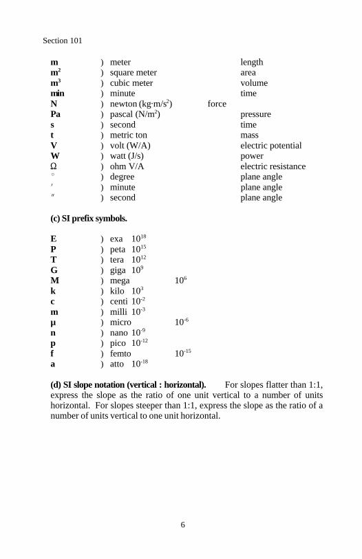
m ) meter lengthm ) square meter area2
m ) cubic meter volume3
min ) minute timeN ) newton (kg m/s ) force2
Pa ) pascal (N/m ) pressure2
s ) second timet ) metric ton massV ) volt (W/A) electric potentialW ) watt (J/s) power
) ohm V/A electric resistance) degree plane angle) minute plane angle) second plane angle
(c) SI prefix symbols.
E ) exa 1018
P ) peta 1015
T ) tera 1012
G ) giga 109
M ) mega 106
k ) kilo 103
c ) centi 10-2
m ) milli 10-3
µ ) micro 10-6
n ) nano 10-9
p ) pico 10-12
f ) femto 10-15
a ) atto 10-18
(d) SI slope notation (vertical : horizontal). For slopes flatter than 1:1,express the slope as the ratio of one unit vertical to a number of unitshorizontal. For slopes steeper than 1:1, express the slope as the ratio of anumber of units vertical to one unit horizontal.
Section 101
7
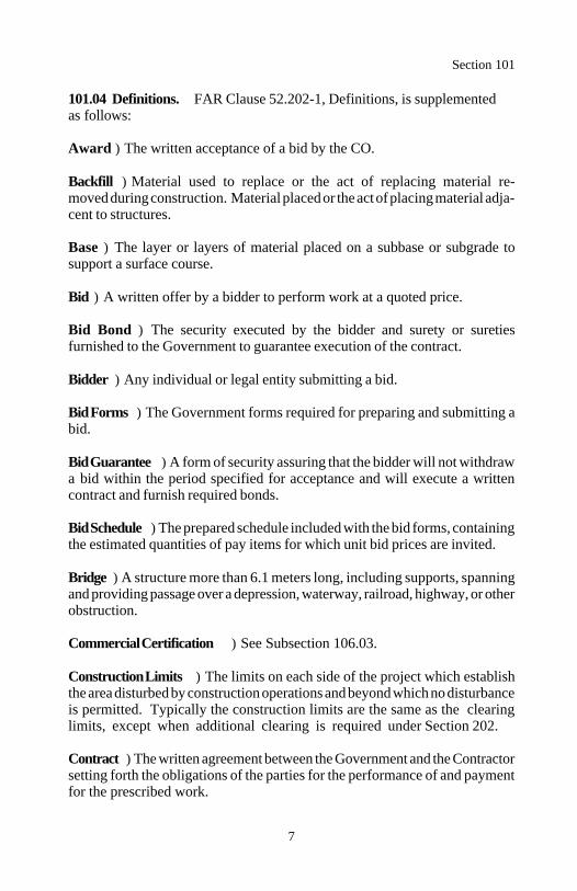
101.04 Definitions. FAR Clause 52.202-1, Definitions, is supplementedas follows:
Award ) The written acceptance of a bid by the CO.
Backfill ) Material used to replace or the act of replacing material re-moved during construction. Material placed or the act of placing material adja-cent to structures.
Base ) The layer or layers of material placed on a subbase or subgrade tosupport a surface course.
Bid ) A written offer by a bidder to perform work at a quoted price.
Bid Bond ) The security executed by the bidder and surety or suretiesfurnished to the Government to guarantee execution of the contract. Bidder ) Any individual or legal entity submitting a bid.
Bid Forms ) The Government forms required for preparing and submitting abid.
Bid Guarantee ) A form of security assuring that the bidder will not withdrawa bid within the period specified for acceptance and will execute a writtencontract and furnish required bonds.
Bid Schedule ) The prepared schedule included with the bid forms, containingthe estimated quantities of pay items for which unit bid prices are invited.
Bridge ) A structure more than 6.1 meters long, including supports, spanningand providing passage over a depression, waterway, railroad, highway, or otherobstruction.
Commercial Certification ) See Subsection 106.03.
Construction Limits ) The limits on each side of the project which establishthe area disturbed by construction operations and beyond which no disturbanceis permitted. Typically the construction limits are the same as the clearinglimits, except when additional clearing is required under Section 202.
Contract ) The written agreement between the Government and the Contractorsetting forth the obligations of the parties for the performance of and paymentfor the prescribed work.
Section 101
8
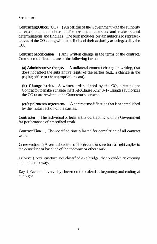
Contracting Officer (CO) ) An official of the Government with the authorityto enter into, administer, and/or terminate contracts and make relateddeterminations and findings. The term includes certain authorized represen-tatives of the CO acting within the limits of their authority as delegated by theCO.
Contract Modification ) Any written change in the terms of the contract.Contract modifications are of the following forms:
(a) Administrative change. A unilateral contract change, in writing, thatdoes not affect the substantive rights of the parties (e.g., a change in thepaying office or the appropriation data).
(b) Change order. A written order, signed by the CO, directing theContractor to make a change that FAR Clause 52.243-4 - Changes authorizesthe CO to order without the Contractor's consent.
(c) Supplemental agreement. A contract modification that is accomplishedby the mutual action of the parties.
Contractor ) The individual or legal entity contracting with the Governmentfor performance of prescribed work.
Contract Time ) The specified time allowed for completion of all contractwork.
Cross-Section ) A vertical section of the ground or structure at right angles tothe centerline or baseline of the roadway or other work.
Culvert ) Any structure, not classified as a bridge, that provides an openingunder the roadway.
Day ) Each and every day shown on the calendar, beginning and ending atmidnight.
Section 101
9
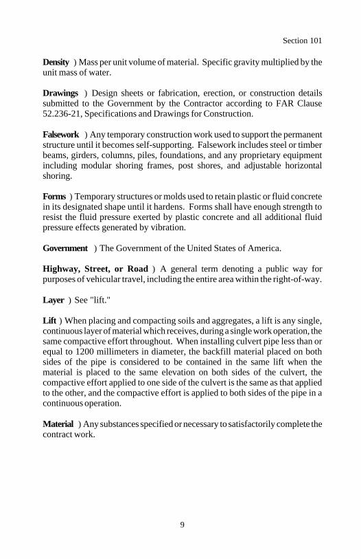
Density ) Mass per unit volume of material. Specific gravity multiplied by theunit mass of water.
Drawings ) Design sheets or fabrication, erection, or construction detailssubmitted to the Government by the Contractor according to FAR Clause52.236-21, Specifications and Drawings for Construction.
Falsework ) Any temporary construction work used to support the permanentstructure until it becomes self-supporting. Falsework includes steel or timberbeams, girders, columns, piles, foundations, and any proprietary equipmentincluding modular shoring frames, post shores, and adjustable horizontalshoring.
Forms ) Temporary structures or molds used to retain plastic or fluid concretein its designated shape until it hardens. Forms shall have enough strength toresist the fluid pressure exerted by plastic concrete and all additional fluidpressure effects generated by vibration.
Government ) The Government of the United States of America.
Highway, Street, or Road ) A general term denoting a public way forpurposes of vehicular travel, including the entire area within the right-of-way.
Layer ) See "lift."
Lift ) When placing and compacting soils and aggregates, a lift is any single,continuous layer of material which receives, during a single work operation, thesame compactive effort throughout. When installing culvert pipe less than orequal to 1200 millimeters in diameter, the backfill material placed on bothsides of the pipe is considered to be contained in the same lift when thematerial is placed to the same elevation on both sides of the culvert, thecompactive effort applied to one side of the culvert is the same as that appliedto the other, and the compactive effort is applied to both sides of the pipe in acontinuous operation.
Material ) Any substances specified or necessary to satisfactorily complete thecontract work.
Section 101
10
Measurement ) The process of identifying the dimensions, quantity, orcapacity of an item. See Section 109 for measurement methods, terms, anddefinitions.
Notice to Proceed ) Written notice to the Contractor to begin the contractwork.
Pavement Structure ) The combination of subbase, base, and surface coursesplaced on a subgrade to support and distribute the traffic load to the roadbed.
Pay Item ) A specific item of work for which a unit and price is provided inthe contract.
Payment Bond ) The security executed by the Contractor and surety orsureties furnished to the Government to assure payments as required by law toall persons supplying labor or material according to the contract.
Performance Bond ) The security executed by the Contractor and surety orsureties and furnished to the Government to guarantee completion of thecontract work.
Plans ) The contract plans furnished by the Government showing the location,type, dimensions, and details of the work.
Production Certification ) See Subsection 106.03.
Profile Grade ) The trace of a vertical plane intersecting a particular surfaceof the proposed road construction located as shown on the plans, usually alongthe longitudinal centerline of the roadbed. Profile grade means either elevationor gradient of the trace according to the context.
Project ) The specific section of the highway or other property on whichconstruction is to be performed under the contract.
Right-of-Way ) Real property used for transportation purposes.
Roadbed ) The graded portion of a highway prepared as a foundation for thepavement structure and shoulders.
Section 101
11
Roadside ) All area within the right-of-way excluding the traveled way andshoulders.
Roadway ) In general, the portion of a highway, including shoulders, forvehicular use. A divided highway has two or more roadways. In constructionspecifications, the portion of a highway within the construction limits.
Roadway Prism ) The volume defined by the area between the original terraincross-section and the final design cross-section multiplied by the horizontaldistance along the centerline of the roadway.
Roller Pass ) One trip of a roller in one direction over any one spot.
Shoring ) This term is used interchangeably with falsework.
Shoulder ) The portion of the roadway contiguous to the traveled way foraccommodation of stopped vehicles, for emergency use, and for lateral supportof the pavement structure.
Sieve ) See AASHTO M 92.
Solicitation ) The complete assembly of related documents (whether attachedor incorporated by reference) furnished to prospective bidders.
Special Contract Requirements ) Additions and revisions to the standard andsupplemental specifications applicable to an individual project.
Specifications ) The written requirements for performing work.
Standard Forms ) Numbered forms issued by the General Services Ad-ministration for use as contract documents.
Standard Plans ) Detailed plans approved for repetitive use and included aspart of the plans.
Standard Specifications ) The Standard Specifications for Construction ofRoads and Bridges on Federal Highway Projects approved for general appli-cation and repetitive use.
Section 101
12
Station ) (1) A measure of distance used for highways and railroads. A stationis equal to one kilometer. (2) A precise location along a survey line.
Structures ) Bridges, culverts, catch basins, drop inlets, retaining walls,cribbing, manholes, endwalls, buildings, sewers, service pipes, underdrains,foundation drains, and other features that may be encountered in the work.
Subbase ) The layer or layers of material placed on a subgrade to support abase.
Subcontract ) The written agreement between the Contractor and an indi-vidual or legal entity prescribing the performance of a specific portion of thework.
Subcontractor ) An individual or legal entity with whom the Contractorsublets part of the work. This includes all subcontractors in any tier.
Subgrade ) The top surface of a roadbed upon which the pavement structure,shoulders, and curbs are constructed.
Substantial Completion ) The point at which the project is complete such thatit can be safely and effectively used by the public without further delays,disruption, or other impediments. For conventional bridge and highway work,the point at which all bridge deck, parapet, pavement structure, shoulder,drainage, sidewalk, permanent signing and markings, traffic barrier, safetyappurtenance, utility, and lighting work is complete.
Substructure ) All of the bridge below the bearings of simple and continuousspans, skewbacks of arches, and tops of footings of rigid frames includingbackwalls, wingwalls, and wing protection railings.
Suitable Material ) Rock or earth material that will provide stable founda-tions, embankments, or roadbeds, and is reasonably free of organic matter,roots, muck, sod, or other detrimental material.
Superintendent ) The Contractor's authorized representative in responsiblecharge of the work.
Superstructure ) The entire bridge except the substructure.
Section 101
13
Supplemental Specifications ) Additions and revisions to the standardspecifications.
Surety ) An individual or corporation legally liable for the debt, default, orfailure of a Contractor to satisfy a contract obligation.
Surface Course ) The top layer or layers of a pavement structure designed toaccommodate the traffic load and resist skidding, traffic abrasion, andweathering.
Target Value (TV) ) A number established as a center for operating a givenprocess. Once established, adjustments should be made in the process asnecessary to maintain a central tendency about the target value. Test resultsobtained from a well controlled process should cluster closely around theestablished target value and the mean of the test results should be equal to ornearly equal to the established target value.
Traveled Way ) The portion of the roadway designated for the movement ofvehicles, exclusive of shoulders.
Unsuitable Material ) Material that is earth, gravel, or sand not adequate (i.e.stability, drainage, etc.) to use in the construction of stable foundations,embankments, or roadbeds.
Work ) The furnishing of all labor, material, equipment, and other incidentalsnecessary to successfully complete the project according to the contract.
14
Section 102. ) BID, AWARD, ANDEXECUTION OF CONTRACT
102.01 Acquisition Regulations. Bid, award, and execution of the contractare governed by the FAR and TAR.
102.02 Preparation of Bids. FAR Clause 52.214-18 - Preparation of Bids) Construction is supplemented as follows.
Execute and submit all required standard forms, bid schedules, and solicita-tion provisions contained in the solicitation as part of the bid.
Complete SF 1442, Solicitation, Offer, and Award , and sign as follows:
(a) Individuals. Sign your individual signature. For individuals doingbusiness as a firm, follow the individual signature with the individual'styped, stamped, or printed name and the words, "an individual doing busi-ness as (name of firm) ".
(b) Partnerships. Submit a list of all partners having authority to bind thepartnership. One of the listed partners must sign on behalf of the partner-ship.
(c) Corporations. Sign in the corporate name, followed by the word "by"and the signature and title of the person authorized to sign. Submit evi-dence from the corporation that the person signing has authority to bind thecorporation.
(d) Joint ventures. All participants in the joint venture shall sign in themanner prescribed in (a) through (c) above. Corporations shall also submita certificate stating that the corporation is authorized to participate in thejoint venture.
One party may sign on behalf of a joint venture if documentation is in-cluded and signed by all members of the joint venture, authorizing theparty with authority to sign for the joint venture.
(e) Agents. When an agent signs, other than as stated in (a) through (d)above, furnish satisfactory evidence that the agent has authority to bind thebidder.
Section 102
15
Insert a unit bid price, in figures, for each pay item for which a quantityappears in the bid schedule. Multiply the unit bid price by the quantity foreach pay item and show the amount bid. Should any mathematical checkmade by the Government show a mistake in the amount bid, the correctedunit price extension shall govern.
When the words "lump sum" appear as a unit bid price, insert an amount bidfor each lump sum pay item.
When the word "contingent sum" or a fixed rate appears as a unit bid price,include the Government inserted amount bid for the item in the total bidamount.
Total all of the amounts bid for each pay item and show the total bid amount.
The quantities shown in the bid schedule are approximate, unless designatedas a contract quantity, and are used for the comparison of bids. Payment willbe made for the actual quantities of work performed and accepted or materialfurnished according to the contract. The scheduled quantities may beincreased, decreased, or deleted. Bid schedule quantities are considered theoriginal contract quantities.
102.03 Bid Guarantee. FAR Clause 52.228-1 - Bid Guarantee is supple-mented as follows:
(a) General. Submit a bid guarantee of not less than 20 percent of theamount of the bid with any bid in excess of $25,000. Submit the bid guar-antee on SF 24, Bid Bond . If the bid guarantee is other than a corporate orindividual surety, sign the SF 24 as the principal and make a statement onthe form pledging the security. Make checks or money orders payable tothe agency issuing the solicitation.
(b) Power of attorney. A corporate surety shall submit a current powerof attorney for the signing agent or attorney-in-fact with each SF 24.
(c) Evidence of guarantee assistance. A surety that has a guarantee ofassistance from the Small Business Administration shall submit a copy ofits "Surety Bond Guarantee Agreement" with each SF 24. In addition,submit a power of attorney for the surety representative identified in theagreement.
Section 102
16
102.04 Individual Surety. FAR Clause 52.228-11 - Pledges of Assets issupplemented as follows.
Complete and date the SF 28, Affidavit of Individual Surety , after the solic-itation date. The individual surety shall personally sign the SF 28. Execu-tion by power of attorney is not acceptable. Bidders cannot serve as theirown surety. Assets named shall be committed to the project with a bankdesignated to serve as trustee.
After reviewing the SF 28, the surety may be requested to provide furtherdocumentation with respect to any of its assets, debts, or encumbrances. Theinformation may be required to be furnished under oath. Failure of the sure-ty to respond with the requested documentation within 7 days of receipt ofthe request is cause for rejection of the surety.
Any material misstatement by the surety, overstatement of assets (either asto ownership or value) or understatement of liabilities is cause for rejectionof the surety. Substitution of individual sureties to support a bid bond afterthe bid opening will not be permitted.
102.05 Public Opening of Bids. Bids will be publicly opened at the timespecified in the SF 1442. Their contents will be made public information.The Government reserves the right to reject bids as set forth in the FAR, Part14.
102.06 Performance and Payment Bonds. Furnish a performance bondin the penal amount of 100 percent of the original contract price and a pay-ment bond as follows:
(a) In the penal amount of 50 percent of the original contract price if thecontract price is not more the $1 million.
(b) In the penal amount of 40 percent of the original contract price if thecontract is more than $1 million but not more than $5 million.
(c) In the amount of $2.5 million if the contract price is more than $5million.
Use SF 25, Performance Bond , and SF 25A, Payment Bond , for submittingthe bonds.

Section 102
17
The requirements contained in Subsections 102.03 and 102.04 relating topower of attorney, evidence of guarantee assistance, and individual suretiesalso apply to performance and payment bonds.
18
Section 103. ) SCOPE OF WORK
103.01 Intent of Contract. The intent of the contract is to provide for theconstruction and completion of the work described. The precise details ofperforming the work are not stipulated except as considered essential for thesuccessful completion of the work. Furnish all labor, material, equipment,tools, transportation, and supplies necessary to complete the work accordingto the contract.
103.02 Disputes. FAR Clause 52.233-1 - Disputes is supplemented asfollows.
When requesting a CO's decision on an interpretation of contract terms for therecovery of increased costs, quantify the amount and, if required by FARClause 52.233-1, certify the amount. Include an explanation of theinterpretation of contract terms, the contract clause under which the claim ismade, all supporting documentation, and adequate cost data to support theamount claimed.
103.03 Value Engineering. FAR Clause 52.248-3 - Value Engineering )Construction is supplemented as follows.
Value engineering proposals that delete work without a related enhancementto the project will not be considered.
103.04 Contractor Records. Upon request, provide records related to thecontract to the Government for up to 3 years after final payment and for longerperiods as provided by law.
Include a provision in all subcontracts at all tiers giving the Government thesame rights as provided above with respect to the subcontractor's records.
103.05 Partnering. To facilitate this contract, the Government offers toparticipate in a formal partnership with the Contractor. This partnership drawson the strengths of each organization to identify and achieve reciprocal goals.Partnering strives to resolve problems in a timely, professional, and non-a-dversarial manner. If problems result in disputes, partnering encourages, butdoes not require, alternative dispute resolution instead of the formal claim pro-cess. The objective is effective and efficient contract performance to achievea quality project within budget and on schedule.
Acceptance of this partnering offer by the Contractor is optional and the

Section 103
19
partnership is bilateral.
If the partnering offer is accepted, mutually agree with the Government on thelevel of organizational involvement and the need for a professional to facilitatethe partnering process. Engage the facilitator and other resources for keyContractor and Government representatives to attend a partnership develop-ment and team-building workshop usually between the time of award and thenotice to proceed. Hold additional progress meetings upon mutual agreement.
The direct cost of partnering facilities, professional facilitation, copying fees,and other miscellaneous costs directly related to partnering meetings will beshared by the Contractor and Government. Secure and pay for facilities,professional fees, and miscellaneous requirements. Provide invoices to theGovernment. The Government will reimburse the Contractor for 50 percent ofthe agreed costs incurred for the partnering process. The Government's sharewill not exceed $20,000.
Each party is responsible for making and paying for its own travel, lodging,and meal arrangements. The time allowed for completion of the project is notaffected by partnering.
20
Section 104. ) CONTROL OF WORK
104.01 Authority of the Contracting Officer (CO). The CO will delegateauthority to representatives to decide on acceptability of work, progress ofwork, suspension of work, interpretation of the contract, and acceptablefulfillment of the contract. The term "CO" includes all authorized represen-tatives of the CO, including inspectors, acting within the limits of their au-thority as delegated by the CO.
104.02 Authority of Government Inspectors. Inspectors are authorized toinspect all work including the preparation, fabrication, or manufacture ofmaterial for the project. The inspector is not authorized to alter or waivecontract requirements, issue instruction contrary to the contract, act as foremanfor the Contractor, or direct the Contractor's operations. The inspector hasauthority to reject work until the issue can be referred to and decided by theCO.
104.03 Specifications and Drawings. FAR Clause 52.236-21 - Specifica-tions and Drawings for Construction is supplemented as follows:
(a) General. Prepare drawings as necessary to adequately construct thework. This includes, but is not limited to, traffic control drawings, falseworkdrawings, stress sheets, anchor bolt layouts, erection drawings, andequipment lists.
Limit drawings to a maximum size of 610 by 920 millimeters. Include oneach drawing and calculation sheet, the project number, name, and otheridentification as shown in the contract.
Furnish 5 sets of drawings and supporting calculations for acceptance beforeperforming work covered by the drawings. If drawings are returned forrevision, correct and resubmit for acceptance. Allow 40 days per submissionfor railroad structures and 30 days per submission for all other structures. Ifdrawings must be resubmitted, the time for acceptance starts over. Obtainprior written approval for changes or deviations from the accepted drawings.
Section 104
21
(b) Specific requirements for concrete and miscellaneous structures.Furnish drawings for cribs, cofferdams, falsework, erection, temporarysupport systems, formwork, detour structures, and other temporary work andmethods of construction proposed. Furnish drawings bearing the seal andsignature of a professional engineer proficient in the pertinent design field.
104.04 Coordination of Contract Documents. The FAR, TAR, specialcontract requirements, plans, supplemental specifications, and standardspecifications are contract documents. A requirement in one document isbinding as though occurring in all the contract documents. The contractdocuments are intended to be complementary and to describe and provide fora complete contract. In case of discrepancy, calculated and shown dimensionsgovern over scaled dimensions. The contract documents govern in thefollowing order:
(a) Federal Acquisition Regulations(b) Transportation Acquisition Regulations(c) Special contract requirements
(d) Plans(e) Supplemental specifications(f) Standard specifications
104.05 Load Restrictions. FAR Clause 52.236-10 - Operations and StorageAreas, paragraph (c), is supplemented as follows.
Comply with all legal load restrictions when hauling material and equipmenton public roads to and from the project. A special permit does not relieve theContractor of liability for damage resulting from the moving of material orequipment.
Unless otherwise permitted, do not operate equipment or vehicles that exceedthe legal load limits over new or existing structures within the project. Repairor replace in an acceptable manner all damages to project work resulting fromthe use of such equipment or vehicles at no cost to the Government.
On the portions of the project used to accommodate public travel, operateconstruction equipment and vehicles in a manner that does not conflict withtraffic flow and minimizes delays to the traveling public.
22
Section 105. ) CONTROL OF MATERIAL
105.01 Source of Supply and Quality Requirements. FAR Clause 52-.236-5 - Material and Workmanship is supplemented as follows.
Select sources and provide acceptable material. Notify the CO of all proposedsources before delivery to the project to expedite material inspection andtesting. Do not incorporate material requiring submittal into the work untilapproved.
Material may be approved at the source of supply before delivery to theproject. Approval does not constitute acceptance. If an approved source doesnot continue to supply acceptable material during the life of the project, furtheruse of that source may be denied.
105.02 Local Material Sources. Sources of rock, sand, gravel, earth, or othernatural material located by the Government in the vicinity of the project maybe identified in the contract. These identified sources may be listed asprovided for the project or only listed as information to aid the Contractor inlocating a source. The decision to use an identified source is solely that of theContractor.
(a) Government-provided sources. The Government will acquire thepermits and rights to remove material from provided sources identified in thecontract and to use such property for a plant site and stockpiles. Test reportsand available historical performance data verifying the presence ofacceptable material are available upon request.
Do not perform work within a Government-provided source until a plan ofoperation for the development of the source is accepted. Perform all worknecessary to produce acceptable material including site development,preparation, erosion control, and restoration.
The quality of material in provided sources is acceptable in general, but maycontain layers or pockets of unacceptable material. It is not feasible toascertain from samples the quality of material for an entire deposit andvariations may be expected. Determine the quantity and type of equipmentand work necessary to select and produce acceptable material.

Section 105
23
(b) Government-listed sources. The Government may list possible materialsources. The Government makes no representation as to the quality orquantity of material, or rights to the availability of material from these sour-ces. These sources are considered to be Contractor-located sources under (c)below.
(c) Contractor-located sources. The Contractor is responsible for thesesources, including established commercial sources. Use sources that fulfillthe contract quantity and quality requirements. Determine the quantity andtypes of equipment and work necessary to select and produce acceptablematerial. Secure all permits and clearances for use of the source and providecopies of the documents.
Provide laboratory test reports and available historical performance dataindicating that acceptable material is available from the source. Do not usematerial from a source that is unacceptable to the Government. Dispose ofunacceptable material and locate another source at no cost to the Gov-ernment.
105.03 Material Source Management. Notify the CO 14 days beforestarting pit operations. Develop and operate within a material source accordingto the accepted plan of operation or written agreement for developing thesource.
Comply with the following applicable requirements:
(a) Before developing a material source, measure the sediment content ofbodies of water adjacent to the work area that will receive drainage from thework area. Control all erosion so the sediment levels in the bodies of waterwithin the drainage area of the work area do not increase.
(b) Strip and stockpile the overburden. After operations are complete, moveall waste back into the source. Neatly trim and flatten the side slopes to theextent practicable. Spread the stockpiled overburden uniformly over thesides and bottom of the mined area. Establish a vegetative cover to blend thesite into the surrounding area.

Section 105
24
105.04 Storing and Handling Material. Store and handle material topreserve its quality and fitness for the work. Stored material approved beforestorage may again be inspected before use in the work. Locate stored materialto facilitate prompt inspection.
Use only approved portions of the right-of-way for storing material and placingplants and equipment. Provide all additional space needed. Do not use privateproperty for storage without written permission of the owner or lessee. Furnishcopies of all agreements. Restore all Government-provided storage sites totheir original condition.
The Contractor is responsible for the security of all stored material.
105.05 Use of Material Found in the Work. Material, such as stone, gravel,or sand, found in the excavation may be used for another pay item whenacceptable. When there is an applicable excavation item in the bid schedule,such material will be paid both as excavation and as the other pay item forwhich it is used. Replace material so used and needed for embankmentor backfill with acceptable material at no cost to the Government.Excavate or remove material only from within the grading limits, as indicatedby the slope and grade lines.
The right to use and process material found in the work does not include theuse and processing of material for nongovernment contract work except for thedisposal of waste material. If the Contractor produces or processes materialfrom Government lands in excess of the quantities required for the contract, theGovernment may:
(a) Take possession of the excess material and direct its use, paying theContractor only for the cost of production, or
(b) Require removal of the material and restoration of the land to asatisfactory condition at no cost to the Government.

25
Section 106.) ACCEPTANCE OF WORK
106.01 Conformity with Contract Requirements. FAR Clause 52.246-12 -Inspection of Construction is supplemented as follows.
References to standard test methods of AASHTO, ASTM, GSA, and otherrecognized standards authorities refer to the methods in effect on the date ofsolicitation for bids.
Perform work according to the contract requirements. Perform all work to thelines, grades, cross-sections, dimensions, and processes or materialrequirements shown on the plans or specified in the contract.
Plan dimensions and contract specification values are the values to be strivedfor and complied with as the design values from which any deviations areallowed. Perform work and provide material that is uniform in character andreasonably close to the prescribed value or within the specified tolerance range.The purpose of a tolerance range is to accommodate occasional minorvariations from the median zone that are unavoidable for practical reasons.
The Government may inspect, sample, or test all work at any time before finalacceptance of the project. When the Government tests work, copies of testreports are furnished to the Contractor upon request. Government tests may ormay not be performed at the work site. If Contractor testing is verified byGovernment testing, the Contractor's results may be used by the Governmentto evaluate work for acceptance. Do not rely on the availability of Governmenttest results for process control.
Acceptable work conforming to the contract will be paid for at the contract unitbid price. Four methods of determining conformity and accepting work aredescribed in Subsections 106.02 to 106.05 inclusive. The primary method ofacceptance is specified in each Section of work. However, work may berejected at any time it is found by any of the methods not to comply with thecontract.
Remove and replace work that does not conform to the contract, or to pre-vailing industry standards where no specific contract requirements are notedat no cost to the Government.
Section 106
26
As an alternative to removal and replacement, the Contractor may submit awritten request to:
(a) Have the work accepted at a reduced price, or(b) Be given permission to perform corrective measures to bring the workinto conformity.
The request shall contain supporting rationale and documentation. Includereferences or data justifying the proposal based on an evaluation of test results,effect on service life, value of material or work, quality, and other tangibleengineering basis. The CO will determine disposition of the nonconformingwork.
When standard manufactured items are specified (such as fence, wire, plates,rolled shapes, pipe conduits, etc., that are identified by gauge, unit mass,section dimensions, etc.), the identification will be considered to be nominalmasses or dimensions. Unless specific contract tolerances are noted, estab-lished manufacturing tolerances will be accepted.
106.02 Visual Inspection. Acceptance is based on visual inspection of thework for compliance with the contract and prevailing industry standards.
106.03 Certification. For material manufactured off-site, use a manufacturerwith an ISO 9000 certification or an effective testing and inspection system.Require the manufacturer to clearly mark the material or packaging with aunique product identification or specification standard to which it is produced.
Material accepted by certification may be sampled and tested at any time. Iffound not in conformance with the contract, the material will be rejected whe-ther in place or not.
One of the following certifications may be required:
(a) Production certification. Material requiring a production certificationis identified in the Acceptance Subsection of each Section. Require themanufacturer to furnish a production certification for each shipment ofmaterial. Include the following with each production certification:
(1) Date and place of manufacture
(2) Test results on material from the same lot and documentation of the
Section 106
27
inspection and testing system
(3) Lot number or other means of cross-referencing to the manufacturer'sinspection and testing system
(4) Manufacturer's statement that the material complies with all con-tract requirements
(5) Manufacturer's signature or other means of demonstrating accounta-bility for the certification
(b) Commercial certification. When a certification is required, but not aproduction certification, furnish one commercial certification for all similarmaterial from the same manufacturer.
A commercial certification is a manufacturer's or Contractor's representationthat the material complies with all contract requirements. The representationmay be labels, catalog data, stamped specification standards, or supplier'scertifications indicating the material is produced to a commercialstandard or specification.
106.04 Measured or Tested Conformance. Provide all necessary productionand processing of the work and control performance of the work so that all ofthe work complies with the contract requirements.
Results from inspection or testing shall have values within the specifiedtolerances or specification limits. When no tolerance values are identified inthe contract, the work will be accepted based on customary manufactur-ing and construction tolerances.
106.05 Statistical Evaluation of Work and Determination of Pay Factor(Value of Work). Statistical evaluation of work is a method of analyzinginspection or test results to determine conformity with the contract re-quirements. The work will be accepted as follows:
(a) General. For work evaluated based on statistical evaluation, both theGovernment and Contractor assume some risk.
Section 106
28
The Government's risk is the probability that work of a rejectable qualitylevel is accepted. The Contractor's risk is the probability that work producedat an acceptable quality level (AQL) is rejected or accepted at a reducedcontract price.
Acceptable quality level is the highest percentage of work outside thespecification limits that is considered acceptable for payment at contractprice. There are 2 categories. Category I is based on an AQL of 5 percent.Category II is based on an AQL of 10 percent. In both cases, the Contrac-tor's risk is 5 percent.
As an incentive to produce uniform quality work and to offset the Con-tractor's risk, a final payment greater than the contract price may be obtainedunder certain conditions.
The quality characteristics to be evaluated, lot size, sampling frequency,sampling location, test methods, specification limits, and category are asfollows:
(1) Quality characteristics. The quality characteristics to be evaluatedare listed in the Acceptance Subsection of each Section.
(2) Lot size. A lot is a discrete quantity of work to which the statisticalevaluation procedure is applied. A lot normally represents the totalquantity of work produced. More than one lot may occur if changes in thetarget values, material sources, or job-mix formula are requested inwriting and approved or adjustments are required as provided under (b).
(3) Sampling frequency. The frequency of sampling is listed in theAcceptance Subsection of each Section. The frequency rate shownnormally results in a minimum of 5 samples, which is the minimumnumber required to perform a statistical evaluation. The maximumobtainable pay factor with 5 samples is 1.01. A minimum of 8 samplesare required to obtain a 1.05 pay factor.
Section 106
29
If the sampling frequencies and quantity of work would otherwise resultin fewer than 8 samples, a written request is required to increase thesampling frequency to provide for a minimum of 8 samples. Provide therequest to increase the sampling frequency at least 48 hours beforebeginning production. An increase in the sampling frequency may resultin a reduced pay factor.
(4) Sampling location. The point of sampling is listed in the AcceptanceSubsection of each Section. The exact location of sampling will bespecified by the CO based on random numbers.
(5) Test methods. The test methods used to test the sample are listed inthe Acceptance Subsection of each Section.
(6) Specification limits. The specification limits for the quality char-acteristics are listed in the contract provisions for the work in question.
(7) Category. The category for the quality characteristics to be analyzedare listed in the Acceptance Subsection of each Section.
(b) Acceptance. The work in the lot will be paid for at a final pay factorwhen all inspection or test results are completed and evaluated.
Before determining the final pay factor, the work may be incorporated intothe project provided the current pay factor does not fall below 0.90. If a lotis concluded with fewer than 5 samples, the material will be evaluated underSubsection 106.04.
If the current pay factor of a lot falls below 0.90, terminate production.Production may resume after the Contractor takes effective and acceptableactions to improve the quality of the production. If it is determined that theresumption of production involves a significant change to the productionprocess, the current lot will be terminated and a new lot begun.
A lot containing an unsatisfactory percentage of nonspecification material(less than 1.00 pay factor) is accepted provided the lowest single pay factorhas not fallen into the reject portion of Table 106-2.
A lot containing an unsatisfactory percentage of nonspecification materialwith the lowest single pay factor falling into the reject portion of Table 106-2is rejected. Remove all rejected material from the work.
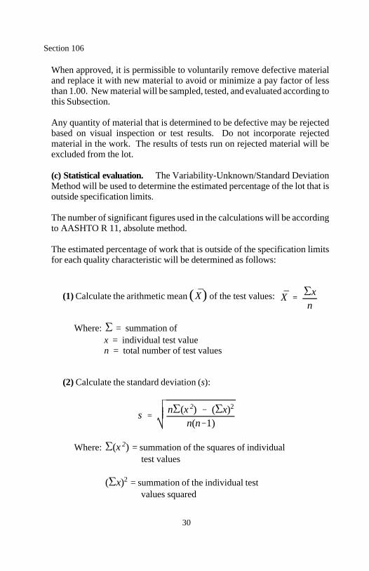
X̄ X̄ xn
s n (x 2) ( x)2
n(n 1)
(x 2)
( x)2
Section 106
30
When approved, it is permissible to voluntarily remove defective materialand replace it with new material to avoid or minimize a pay factor of lessthan 1.00. New material will be sampled, tested, and evaluated according tothis Subsection.
Any quantity of material that is determined to be defective may be rejectedbased on visual inspection or test results. Do not incorporate rejectedmaterial in the work. The results of tests run on rejected material will beexcluded from the lot.
(c) Statistical evaluation. The Variability-Unknown/Standard DeviationMethod will be used to determine the estimated percentage of the lot that isoutside specification limits.
The number of significant figures used in the calculations will be accordingto AASHTO R 11, absolute method.
The estimated percentage of work that is outside of the specification limitsfor each quality characteristic will be determined as follows:
(1) Calculate the arithmetic mean ( ) of the test values:
Where: = summation of x = individual test value n = total number of test values
(2) Calculate the standard deviation (s):
Where: = summation of the squares of individual test values
= summation of the individual test values squared
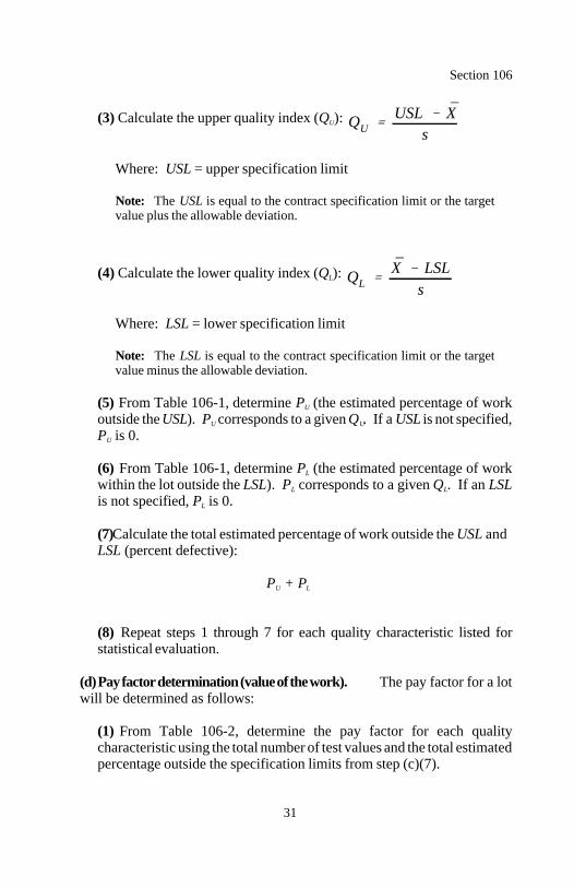
QUUSL X̄
s
QLX̄ LSL
s
Section 106
31
(3) Calculate the upper quality index (Q ): U
Where: USL = upper specification limit
Note: The USL is equal to the contract specification limit or the targetvalue plus the allowable deviation.
(4) Calculate the lower quality index (Q ): L
Where: LSL = lower specification limit
Note: The LSL is equal to the contract specification limit or the targetvalue minus the allowable deviation.
(5) From Table 106-1, determine P (the estimated percentage of workU
outside the USL). P corresponds to a given Q . If a USL is not specified,U U
P is 0.U
(6) From Table 106-1, determine P (the estimated percentage of workL
within the lot outside the LSL). P corresponds to a given Q . If an LSLL L
is not specified, P is 0.L
(7) Calculate the total estimated percentage of work outside the USL andLSL (percent defective):
P + P U L
(8) Repeat steps 1 through 7 for each quality characteristic listed forstatistical evaluation.
(d) Pay factor determination (value of the work). The pay factor for a lotwill be determined as follows:
(1) From Table 106-2, determine the pay factor for each qualitycharacteristic using the total number of test values and the total estimatedpercentage outside the specification limits from step (c)(7).
Section 106
32
(2) When all quality characteristics for a lot are category I, the lot payfactor is based on the lowest single pay factor for any category I qualitycharacteristic. The maximum obtainable pay factor is 1.05 (with aminimum of 8 test values).
(3) When quality characteristics for a lot are both category I and II, the lotpay factor is based on the following:
(a) When all category II quality characteristics are 1.00, the lotpayment is based on the lowest single pay factor for all category Icharacteristics. The maximum obtainable pay factor is 1.05 (with aminimum of 8 test values).
(b) When any category II quality characteristic is less than 1.00, the lotpayment is based on the lowest single pay factor for any quality char-acteristic.
(4) When all quality characteristics for a lot are category II, the lot payfactor is based on the lowest single pay factor for any category II qualitycharacteristic. The maximum obtainable pay factor is 1.00.
(5) Adjusted payment for material in a lot will be made at a price deter-mined by multiplying the contract unit bid price by the lot pay factor asdetermined above.
106.06 Inspection at the Plant. Work may be inspected at the point ofproduction or fabrication. Manufacturing plants may be inspected for com-pliance with specified manufacturing methods. Material samples may beobtained for laboratory testing for compliance with quality requirements.Allow full entry at all times to the parts of the plant producing the work.
106.07 Partial and Final Acceptance. Maintain the work during con-struction and until the project is accepted. FAR Clause 52.236-11 - Use andPossession Prior to Completion is supplemented as follows:
(a) Partial acceptance. When a separate portion of the project is com-pleted, a final inspection of that portion may be requested. If the portion iscomplete and in compliance with the contract, it will be accepted, and theContractor will be relieved of further responsibility for maintenance of thecompleted portion. Partial acceptance does not void or alter any of the termsof the contract.
Section 106
33
When public traffic is accommodated through construction and begins usingsections of roadway as they are completed, continue maintenance of suchsections until final acceptance.
(b) Final acceptance. When notified that the entire project is complete, aninspection will be scheduled. If all work is determined complete, theinspection will constitute the final inspection, and the Contractor will benotified in writing of final acceptance as of the date of the final inspection.Final acceptance relieves the Contractor of further responsibility for themaintenance of the project.
If the inspection discloses any unsatisfactory work, the Contractor willreceive a list of the work that is incomplete or requires correction. Immedi-ately complete or correct the work. Furnish notification when the work hasbeen completed as provided above.
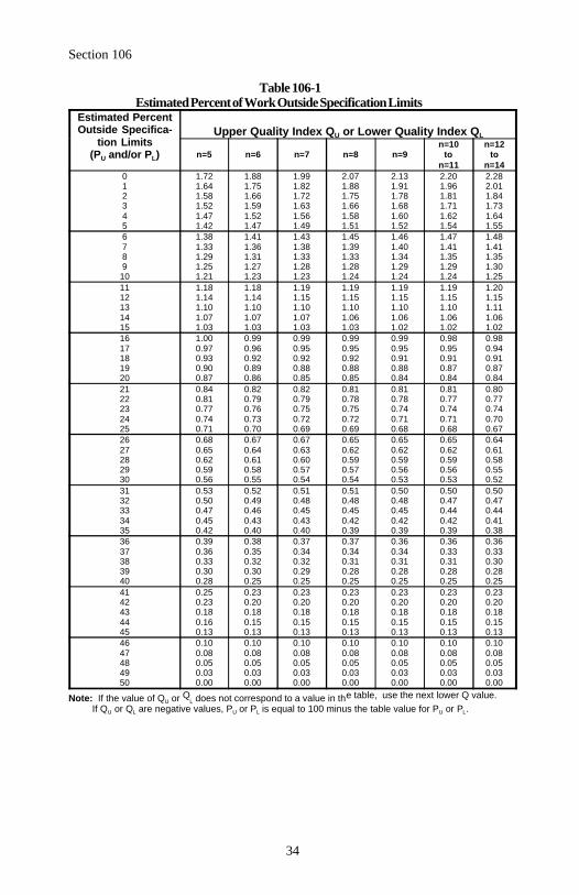
Section 106
34
Table 106-1Estimated Percent of Work Outside Specification Limits
Estimated PercentOutside Specifica-
tion Limits(P and/or P )U L
Upper Quality Index Q or Lower Quality Index QU L
n=5 n=6 n=7 n=8 n=9 to ton=10 n=12
n=11 n=140 1.72 1.88 1.99 2.07 2.13 2.20 2.281 1.64 1.75 1.82 1.88 1.91 1.96 2.012 1.58 1.66 1.72 1.75 1.78 1.81 1.843 1.52 1.59 1.63 1.66 1.68 1.71 1.734 1.47 1.52 1.56 1.58 1.60 1.62 1.645 1.42 1.47 1.49 1.51 1.52 1.54 1.556 1.38 1.41 1.43 1.45 1.46 1.47 1.487 1.33 1.36 1.38 1.39 1.40 1.41 1.418 1.29 1.31 1.33 1.33 1.34 1.35 1.359 1.25 1.27 1.28 1.28 1.29 1.29 1.30
10 1.21 1.23 1.23 1.24 1.24 1.24 1.2511 1.18 1.18 1.19 1.19 1.19 1.19 1.2012 1.14 1.14 1.15 1.15 1.15 1.15 1.1513 1.10 1.10 1.10 1.10 1.10 1.10 1.1114 1.07 1.07 1.07 1.06 1.06 1.06 1.0615 1.03 1.03 1.03 1.03 1.02 1.02 1.0216 1.00 0.99 0.99 0.99 0.99 0.98 0.9817 0.97 0.96 0.95 0.95 0.95 0.95 0.9418 0.93 0.92 0.92 0.92 0.91 0.91 0.9119 0.90 0.89 0.88 0.88 0.88 0.87 0.8720 0.87 0.86 0.85 0.85 0.84 0.84 0.8421 0.84 0.82 0.82 0.81 0.81 0.81 0.8022 0.81 0.79 0.79 0.78 0.78 0.77 0.7723 0.77 0.76 0.75 0.75 0.74 0.74 0.7424 0.74 0.73 0.72 0.72 0.71 0.71 0.7025 0.71 0.70 0.69 0.69 0.68 0.68 0.6726 0.68 0.67 0.67 0.65 0.65 0.65 0.6427 0.65 0.64 0.63 0.62 0.62 0.62 0.6128 0.62 0.61 0.60 0.59 0.59 0.59 0.5829 0.59 0.58 0.57 0.57 0.56 0.56 0.5530 0.56 0.55 0.54 0.54 0.53 0.53 0.5231 0.53 0.52 0.51 0.51 0.50 0.50 0.5032 0.50 0.49 0.48 0.48 0.48 0.47 0.4733 0.47 0.46 0.45 0.45 0.45 0.44 0.4434 0.45 0.43 0.43 0.42 0.42 0.42 0.4135 0.42 0.40 0.40 0.39 0.39 0.39 0.3836 0.39 0.38 0.37 0.37 0.36 0.36 0.3637 0.36 0.35 0.34 0.34 0.34 0.33 0.3338 0.33 0.32 0.32 0.31 0.31 0.31 0.3039 0.30 0.30 0.29 0.28 0.28 0.28 0.2840 0.28 0.25 0.25 0.25 0.25 0.25 0.2541 0.25 0.23 0.23 0.23 0.23 0.23 0.2342 0.23 0.20 0.20 0.20 0.20 0.20 0.2043 0.18 0.18 0.18 0.18 0.18 0.18 0.1844 0.16 0.15 0.15 0.15 0.15 0.15 0.1545 0.13 0.13 0.13 0.13 0.13 0.13 0.1346 0.10 0.10 0.10 0.10 0.10 0.10 0.1047 0.08 0.08 0.08 0.08 0.08 0.08 0.0848 0.05 0.05 0.05 0.05 0.05 0.05 0.0549 0.03 0.03 0.03 0.03 0.03 0.03 0.0350 0.00 0.00 0.00 0.00 0.00 0.00 0.00
Q e table, use the next lower Q value.Note: If the value of Q orU L does not correspond to a value in th If Q or Q are negative values, P or P is equal to 100 minus the table value for P or P .U L U L U L
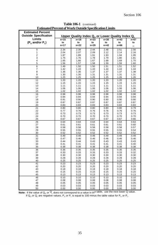
Section 106
35
Table 106-1 (continued)Estimated Percent of Work Outside Specification Limits
Estimated PercentOutside Specification
Limits(P and/or P )U L
Upper Quality Index Q or Lower Quality Index QU Ln=15 n=18 n=23 n=30 n=43 n=67
to to to to to ton=17 n=22 n=29 n=42 n=66
0 2.34 2.39 2.44 2.48 2.51 2.561 2.04 2.07 2.09 2.12 2.14 2.162 1.87 1.89 1.91 1.93 1.94 1.953 1.75 1.76 1.78 1.79 1.80 1.814 1.65 1.66 1.67 1.68 1.69 1.705 1.56 1.57 1.58 1.59 1.59 1.606 1.49 1.50 1.50 1.51 1.51 1.527 1.42 1.43 1.43 1.44 1.44 1.448 1.36 1.36 1.37 1.37 1.37 1.389 1.30 1.30 1.31 1.31 1.31 1.31
10 1.25 1.25 1.25 1.25 1.26 1.2611 1.20 1.20 1.20 1.20 1.20 1.2012 1.15 1.15 1.15 1.15 1.15 1.1513 1.11 1.11 1.11 1.11 1.11 1.1114 1.06 1.06 1.06 1.06 1.06 1.0615 1.02 1.02 1.02 1.02 1.02 1.0216 0.98 0.98 0.98 0.98 0.98 0.9817 0.94 0.94 0.94 0.94 0.94 0.9418 0.91 0.90 0.90 0.90 0.90 0.9019 0.87 0.87 0.87 0.87 0.87 0.8720 0.83 0.83 0.83 0.83 0.83 0.8321 0.80 0.80 0.80 0.80 0.80 0.7922 0.77 0.76 0.76 0.76 0.76 0.7623 0.73 0.73 0.73 0.73 0.73 0.7324 0.70 0.70 0.70 0.70 0.70 0.7025 0.67 0.67 0.67 0.67 0.67 0.6626 0.64 0.64 0.64 0.64 0.64 0.6327 0.61 0.61 0.61 0.61 0.61 0.6028 0.58 0.58 0.58 0.58 0.58 0.5729 0.55 0.55 0.55 0.55 0.55 0.5430 0.52 0.52 0.52 0.52 0.52 0.5231 0.49 0.49 0.49 0.49 0.49 0.4932 0.47 0.46 0.46 0.46 0.46 0.4633 0.44 0.44 0.43 0.43 0.43 0.4334 0.41 0.41 0.41 0.41 0.41 0.4035 0.38 0.38 0.38 0.38 0.38 0.3836 0.36 0.35 0.35 0.35 0.35 0.3537 0.33 0.33 0.33 0.33 0.33 0.3238 0.30 0.30 0.30 0.30 0.30 0.3039 0.28 0.28 0.28 0.28 0.28 0.2840 0.25 0.25 0.25 0.25 0.25 0.2541 0.23 0.23 0.23 0.23 0.23 0.2342 0.20 0.20 0.20 0.20 0.20 0.2043 0.18 0.18 0.18 0.18 0.18 0.1844 0.15 0.15 0.15 0.15 0.15 0.1545 0.13 0.13 0.13 0.13 0.13 0.1346 0.10 0.10 0.10 0.10 0.10 0.1047 0.08 0.08 0.08 0.08 0.08 0.0848 0.05 0.05 0.05 0.05 0.05 0.0549 0.03 0.03 0.03 0.03 0.03 0.0350 0.00 0.00 0.00 0.00 0.00 0.00
Q e table, use the next lower Q value.Note: If the value of Q orU L does not correspond to a value in th If Q or Q are negative values, P or P is equal to 100 minus the table value for P or P .U L U L U L
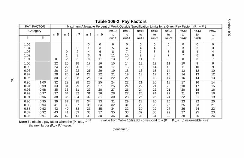
Section 106
36
Table 106-2 Pay FactorsPAY FACTOR Maximum Allowable Percent of Work Outside Specification Limits for a Given Pay Factor (P + P ) U L
Categoryn=5 n=6 n=7 n=8 n=9
n=10to
n=11
n=12to
n=14
n=15to
n=17
n=18to
n=22
n=23to
n=29
n=30to
n=42
n=43to
n=66
n=67to
I II
1.051.041.031.021.01 0
012
0235
01468
036911
0581113
047
1012
047911
046810
03579
03578
03468
03467
1.000.990.980.970.96
2224262830
2022242628
1820222426
1719212325
1618202224
1517192122
1416181921
1315161819
1214151718
1113141617
1011131416
910121314
89101213
0.950.940.930.920.91
1.000.990.980.970.96
3233353738
2931333436
2829313234
2628293132
2527283031
2425272830
2224252728
2122242526
2021222425
1820212224
1718202122
1617181921
1415161819
0.900.890.880.870.86
0.950.940.930.920.91
3941424345
3738404142
3537383941
3435363839
3334353738
3132343536
2931323334
2829303233
2628293031
2526272930
2325262728
2223242526
2021222324
or P oes not correspond to a (P P is table, useNote: To obtain a pay factor when the (P and/ U L U L) value from Table 106-1 d + ) value in th
the next larger (P + P ) value.U L(continued)
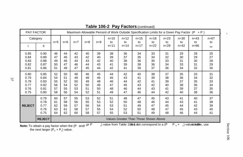
Section 106
37
Table 106-2 Pay Factors (continued)
PAY FACTOR Maximum Allowable Percent of Work Outside Specification Limits for a Given Pay Factor (P + P ) U L
Categoryn=5 n=6 n=7 n=8 n=9
n=10to
n=11
n=12to
n=14
n=15to
n=17
n=18to
n=22
n=23to
n=29
n=30to
n=42
n=43to
n=66
n=67to
I II
0.850.840.830.820.81
0.900.890.880.870.86
4647495051
4445464749
4243444647
4042434445
3940424344
3839404142
3637383941
3435363839
3334353637
3132333436
2930313334
2829303132
2527282930
0.800.790.780.770.760.75
0.850.840.830.820.810.80
525455565758
505152545556
484950525354
464849505152
454648495051
444546474849
424344454647
404142434446
383941424344
373839404142
353637383940
333435363738
313233343536
REJECT
0.790.780.770.760.75
6061626364
5758596162
5556575860
5355565758
5253545557
5152535455
4850515253
4748495051
4546474849
4344454748
4143444546
4041424344
3738394041
REJECT Values Greater Than Those Shown Above
or P oes not correspond to a (P P is table, useNote: To obtain a pay factor when the (P and/ U L U L) value from Table 106-1 d + ) value in th
the next larger (P + P ) value.U L
38
Section 107.) LEGAL RELATIONS AND RESPONSIBILITY TO THE PUBLIC
107.01 Laws to be Observed. FAR Clause 52.236-7 - Permits and Respon-sibilities is supplemented as follows.
Comply with all applicable laws, ordinances, safety codes, regulations, orders,and decrees. Protect and indemnify the Government and its representativesagainst any claim or liability arising from or based on the alleged violation ofthe same.
All permits and agreements obtained by the Government for performing thework are included in the contract. Comply with the requirements of thesepermits and/or agreements. Obtain all additional permits or agreements andmodifications to Government obtained permits or agreements that are requiredby the Contractor's methods of operation.
107.02 Protection and Restoration of Property and Landscape. FARClause 52.236-9 - Protection of Existing Vegetation, Structures, Equipment,Utilities, and Improvements is supplemented as follows.
Preserve public and private property and protect monuments established for thepurpose of perpetuating horizontal, vertical, cadastral, or boundary control.When necessary to destroy a monument, reestablish the monument accordingto applicable state statute or by the direction of the agency or individual whoestablished the monument.
Do not disturb the area beyond the construction limits.
Do not excavate, remove, damage, alter, or deface any archeological or paleon-tological remains or specimens. Control the actions of employees andsubcontractors on the project to ensure that protected sites are not disturbed ordamaged. Should any of these items be encountered, suspend operations at thediscovery site, notify the CO, and continue operations in other areas. The COwill inform the Contractor when operations may resume at the discovery site.
When utilities are to be relocated or adjusted, the Government will notify allutility owners affected by the relocations or adjustments. The relocations oradjustments will be performed by others within the time frames specified, orotherwise as soon as practicable.
Section 107
39
Before beginning work in an area, the Contractor shall have all utility ownerslocate their utilities. Protect utilities from construction operations. Cooperatewith utility owners to expedite the relocation or adjustment of their utilities tominimize interruption of service and duplication of work.
If utility services are interrupted as a result of damage by the construction,immediately notify the utility owner and other proper authorities. Cooperatewith them until service is restored. Do not work around fire hydrants untilprovisions for continued service are made and approved by the local fireauthority.
If utility adjustment work, not included in the contract, is required, compen-sation for the work will be provided under applicable clauses of the contract.Satisfactorily repair damage, due to the fault or negligence of the Contractor,at no cost to the Government.
Repair of damage to underground utilities that were not shown on the plans oridentified before construction and not caused by the fault or negligence of theContractor will be paid for by the Government.
107.03 Bulletin Board. Furnish a weatherproof bulletin board of suitable sizeand construction for continuous display of posters and other informationrequired by the contract. Erect and maintain the bulletin board at a conspic-uously accessible location on the project and remove and dispose of it afterproject final acceptance.
Display each of the following documents on the bulletin board:
(a) "Equal Opportunity" poster, according to FAR Clause 52.222-26(b) "Notice" that the project is subject to Title 18, U.S. Criminal Code,Section 1020(c) "Notice to Employees" poster, WH-1321, regarding proper pay(d) "Safety and Health Protection on the Job" poster, according to Title 29,Code of Federal Regulations, Part 1926(e) "General Wage Decision" contained in the contract(f) Company equal employment opportunity policy
107.04 Railroad Protection. The Government will obtain the necessarypermits and agreements from the railroad for specified contract work forrelocating railroads or for work at railroad crossings. Make arrangements forall other work that, due to the method of operation, may also impact therailroad. Furnish copies of all permits and agreements.
Section 107
40
Conduct the work covered by the railroad permit or agreement in a mannersatisfactory to the railroad. Do not interfere with railroad operations. If theconstruction damages railroad property, reimburse the railroad for all damagesor, at the railroad's option, repair the damage at no cost to the Government.
Do not cross railroad tracks, with vehicles or equipment, except at existing andopen public grade crossings or railroad approved temporary grade crossings.If there is a need for a temporary grade crossing, make the necessaryarrangements with the railroad for its construction, protection, and removal.Reimburse the railroad for all temporary grade crossing work or, at therailroad's option, perform the work.
The requirements of the railroad are as follows:
(a) Indemnify and hold harmless the railroad according to Subsection107.05. Carry insurance meeting the following minimums:
(1) Worker's compensation insurance. Minimum required by law.
(2) Bodily injury liability insurance. $2,000,000 each occurrence.
(3) Property damage liability insurance. $2,000,000 aggregate coverage.
(4) Railroad protective public liability and property damage liability insurance. $2,000,000 each occurrence. $6,000,000 aggregate coverage.
(b) Notify the railroad in writing not less than 1 week before beginningconstruction within the railroad right-of-way. Secure permission from therailroad before performing work within the railroad right-of-way. Conferwith the railroad concerning clearance requirements, operations, and safetyregulations.
(c) Reimburse the railroad for all flaggers and watchers provided by therailroad because of the work. The railroad generally requires 2 watchers orflaggers during construction operations that interfere with the railroad'stracks or traffic, that violate the railroad's operating clearances, or thatinvolve a reasonable probability of accidental hazard to railroad traffic.
Section 107
41
Flaggers are also furnished whenever, in the railroad's opinion, such pro-tection is needed. Notify the railroad 36 hours in advance of requiredprotective services.
(d) Railroad employees are paid the prevailing railroad hourly rate forregularly assigned 8-hour days for the work classification and overtimeaccording to labor agreements and schedules in effect when the work isperformed.
(e) Wage rates are subject to change by law or agreement between therailroad and employees and may be retroactive. If the wage rates change,reimburse the railroad based on the new rates.
(f) Reimburse the railroad monthly for the cost of all services performed bythe railroad. Furnish satisfactory evidence that the railroad has receivedfull reimbursement before final acceptance.
(g) Do not store any material, supplies, or equipment closer than 5 metersfrom the centerline of any railroad track.
(h) Upon completion of the work, remove all equipment and surplus materialand leave the railroad right-of-way in a neat condition satisfactory to therailroad.
107.05 Responsibility for Damage Claims. Indemnify and hold harmless theGovernment, its employees, and its consultants from suits, actions, or claimsbrought for injuries or damage received or sustained by any person, persons,or property resulting from the construction operations or arising out of thenegligent performance of the contract.
Procure and maintain until final acceptance of the contract, liability insuranceof the types and limits specified below. Obtain insurance from companiesauthorized to do business in the appropriate state. The insurance shall coverall operations under the contract whether performed by the Contractor or bysubcontractors.
Before work begins, furnish "certificates of insurance" certifying that thepolicies will not be changed or canceled until 30 days written notice has beengiven to the Government. Insurance coverage in the minimum amounts setforth below shall not relieve the Contractor of liability in excess of thecoverage.
Carry insurance meeting the following minimums:
Section 107
42
(a) Worker's compensation insurance. Minimum required by law.
(b) Comprehensive or commercial general liability insurance.
(1) Personal injury and property damage coverage(2) Contractual liability coverage(3) Completed operations liability coverage(4) $1,000,000 combined single limit for each occurrence(5) $2,000,000 general aggregate limit
(c) Automobile liability insurance. $1,000,000 combined single limitfor each occurrence.
107.06 Contractor's Responsibility for Work. Assume responsibility for allwork until final acceptance except as provided in Subsection 106.07. Thisincludes periods of suspended work. Protect the work against injury, loss, ordamage from all causes whether arising from the execution or nonexecutionof the work.
Maintain public traffic according to Section 156. Rebuild, repair, restore, andmake good all losses, injuries, or damages to any portion of the work. Thisincludes losses, injuries, or damages caused by vandalism, theft, ac-commodation of public traffic, and weather that occurs during the contract.
The Government will only be responsible for losses, injuries, and damagescaused by declared enemies and terrorists of the Government and cataclysmicnatural phenomenon such as tornadoes, earthquakes, major floods, andofficially declared natural disasters.
107.07 Furnishing Right-Of-Way. The Government will obtain allright-of-way.
107.08 Sanitation, Health, and Safety. FAR Clause 52.236-13 - AccidentPrevention is supplemented as follows.
Observe rules and regulations of Federal, state, and local health officials. Donot permit any worker to work in surroundings or under conditions which areunsanitary, hazardous, or dangerous.
Section 107
43
Admit any OSHA inspector or other legally responsible official involved insafety and health administration to the project work site upon presentation ofproper credentials.
Report accidents on forms furnished by the Government or, with priorapproval, on forms used to report accidents to other agencies or insurancecarriers. Maintain a "Log of Occupational Injuries and Illnesses," OSHA form100, and make it available for inspection.
107.09 Legal Relationship of the Parties. In the performance of thecontract, the Contractor is an independent contractor and neither the Contractornor anyone used or employed by the Contractor shall be an agent, employee,servant, or representative of the Government. The Contractor's independentcontractor status does not limit the Government's general rights under thecontract including inspection of work, specification of safety measures andequipment, and ability to stop work.
107.10 Environmental Protection. FAR Clause 52.223-2 - Clean Air andWater is supplemented as follows.
Do not operate mechanized equipment or discharge or otherwise place anymaterial within the wetted perimeter of any waters of the U.S. within the scopeof the Clean Water Act (33 USC § 1251 et seq.). This includes wetlands,unless authorized by a permit issued by the U.S. Army Corps of Engineersaccording to 33 USC § 1344, and, if required, by any state agency havingjurisdiction over the discharge of material into the waters of the U.S. In theevent of an unauthorized discharge:
(a) Immediately prevent further contamination.(b) Immediately notify appropriate authorities.(c) Mitigate damages as required.
Comply with the terms and conditions of any permits that are issued for theperformance of work within the wetted perimeter of the waters of the U.S.
Separate work areas, including material sources, by the use of a dike or othersuitable barrier that prevents sediment, petroleum products, chemicals, or otherliquid or solid material from entering the waters of the U.S. Use care inconstructing and removing the barriers to avoid any discharge of material into,or the siltation of, the water. Remove and properly dispose of the sediment orother material collected by the barrier.

Section 107
44
107.11 Protection of Forests, Parks, and Public Lands. Comply with allregulations of the state fire marshal, conservation commission, Forest Service,National Park Service, Bureau of Land Management, Bureau of Indian Affairs,or other authority having jurisdiction governing the protection of landincluding or adjacent to the project.
45
Section 108.) PROSECUTION AND PROGRESS
108.01 Commencement, Prosecution, and Completion of Work. FARClause 52.211-10 - Commencement, Prosecution, and Completion of Work issupplemented as follows.
A preconstruction conference will be held after the contract is awarded andbefore the notice to proceed is issued. Seven days before the preconstructionconference, furnish three copies of the preliminary construction scheduleaccording to Section 155.
Furnish notification at least 24 hours in advance of resuming work after asuspension.
108.02 Subcontracting. FAR Clauses 52.219-14 - Limitations on subcon-tracting, 52.222-11 - Subcontracts, and 52.236-1 - Performance of Work bythe Contractor are supplemented as follows.
Subcontracting does not relieve the Contractor of liability and responsibilityunder the contract and does not create any contractual relation betweensubcontractors and the Government. The Contractor is liable and responsiblefor any action or lack of action of subcontractors.
Within 14 days of subcontract award, submit an SF 1413 with Part I completedand complete other forms that may be provided by the Government to clearlyshow the work subcontracted and the total dollar amount of the subcontract.For subcontracts involving on-site labor, require the subcontractor to completePart II of the SF 1413 and complete other forms that may be provided by theGovernment. Submit a separate statement documenting the cumulative amountof all on-site subcontracts to date as a percentage of the original contractamount. Furnish this information on all subcontracts at lower tiers.
In FAR Clauses 52.219-8 - Utilization of Small Business Concerns and SmallDisadvantaged Business Concerns and 52.232-27 - Prompt Payment forConstruction Contracts, the subcontracts include both on-site and off-site workand supply contracts. In FAR Clause 52.219-14 - Limitations onSubcontracting or in FAR Clause 52.236-1 - Performance of Work by theContractor, the percentage of work performed on-site by the Contractor will becomputed as 100 percent less the combined initial dollar amount of all subcon-tracts involving on-site labor as a percent of the original dollar amount of thecontract.
Section 108
46
108.03 Determination and Extension of Contract Time. FAR Clause52.211-10 - Commencement, Prosecution, and Completion of Work is sup-plemented as follows.
Only delays or modifications that affect critical activities or cause noncriticalactivities to become critical will be considered for time extensions.
When Critical Path Method schedules are used, no time extension will be madefor delays or modifications that use available float time as shown in the currentconstruction schedule required by Section 155.
Time will not be extended for a claim that states insufficient time was providedin the contract.
When requesting a time extension, follow the applicable contract clauses.Make the request in writing and include the following:
(a) Contract clause(s) under which the request is being made.
(b) Detailed narrative description of the reasons for the requested contracttime adjustment including the following:
(1) Cause of the impact affecting time(2) Start date of the impact(3) Duration of the impact(4) Activities affected(5) Methods to be employed to mitigate the impact
(c) Suggested new completion date or number of days supported by currentand revised construction schedules according to Section 155.
108.04 Failure to Complete Work on Time. FAR Clause 52.211-12 - Liq-uidated Damages ) Construction is supplemented as follows.
Liquidated damages in the amount specified in Table 108-1 will be assessed foreach day beyond the time allowed to complete the contract until substantialcompletion of the work.
Liquidated damages in an amount equal to 20 percent of the amount specifiedin Table 108-1 will be assessed for each day beyond the time allowed to com-plete the contract beginning with the day after substantial completion andending with the date of final completion and acceptance.
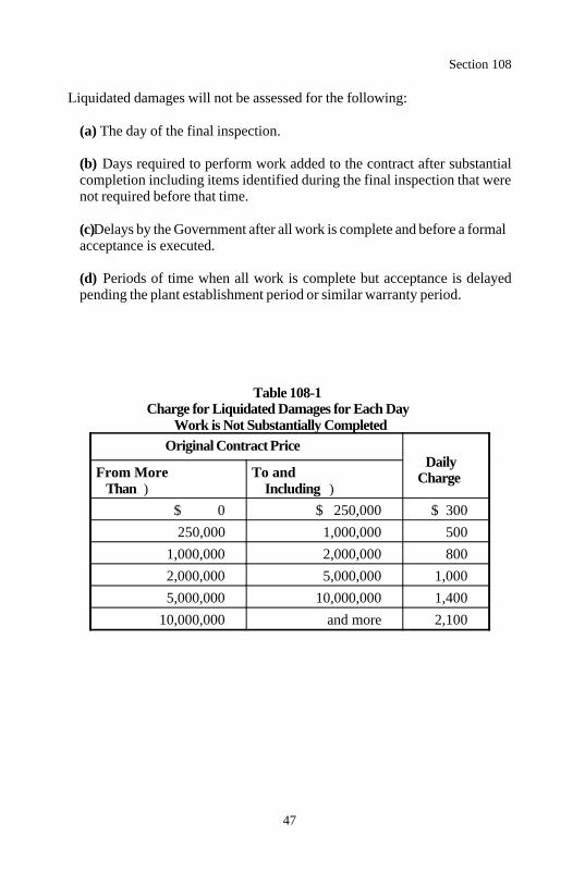
Section 108
47
Liquidated damages will not be assessed for the following:
(a) The day of the final inspection.
(b) Days required to perform work added to the contract after substantialcompletion including items identified during the final inspection that werenot required before that time.
(c) Delays by the Government after all work is complete and before a formalacceptance is executed.
(d) Periods of time when all work is complete but acceptance is delayedpending the plant establishment period or similar warranty period.
Table 108-1Charge for Liquidated Damages for Each Day
Work is Not Substantially CompletedOriginal Contract Price
Daily ChargeFrom More To and
Than ) Including )$ 0 $ 250,000 $ 300250,000 1,000,000 500
1,000,000 2,000,000 8002,000,000 5,000,000 1,0005,000,000 10,000,000 1,400
10,000,000 and more 2,100
Section 108
48
108.05 Stop Order. The CO may order the performance of the work to bestopped, either in whole or in part, for such periods deemed necessary due tothe following:
(a) Weather or soil conditions considered unsuitable for prosecution of thework, or
(b) Failure of the Contractor to:
(1) Correct conditions unsafe for the workers or the general public.(2) Carry out written orders given by the CO.(3) Perform any provision of the contract.
No adjustment in contract time or amount will be made for stop orders issuedunder (a) or (b) above, except an adjustment in contract time as provided byFAR Clause 52.249-10 - Default (Fixed-Price Construction) may be madewhen the Contractor is able to demonstrate that the weather was unusuallysevere based on the most recent 10 years of historical data.
49
Section 109.) MEASUREMENT AND PAYMENT
109.01 Measurement Methods. Take or convert all measurements of workaccording to the International System of Units, ASTM E 380.
Unless otherwise specified, measure when the work is in place, complete, andaccepted. Measure the actual work performed, except do not measure workoutside the design limits or other adjusted or specified limits (staked limits).Measure structures to the neat lines shown on the plans or to approved lines ad-justed to fit field conditions.
The Measurement Subsection of each Section details specifics and exceptionsfor measuring work under each Section.
The CO will verify Contractor measurements.
109.02 Measurement Terms and Definitions. Unless otherwise specified,the meanings of the following terms are as follows:
(a) Contract quantity. The quantity to be paid is the quantity shown in thebid schedule. The contract quantity will be adjusted for authorized changesthat affect the quantity or for errors made in computing this quantity. If thereis evidence that a quantity specified as a contract quantity is incorrect, submitcalculations, drawings, or other evidence indicating why the quantity is inerror and request, in writing, that the quantity be adjusted.
(b) Cubic meter (m ).3
(1) Cubic meter in place. Measure solid volumes by a method approvedby the CO or by the average end area method as follows:
(a) Take cross-sections of the original ground and use with design orstaked templates or take other comparable measurements to determinethe end areas. Do not measure work outside of the established lines orslopes.
(b) If any portion of the work is acceptable but is not completed to theestablished lines and slopes, retake cross-sections or comparablemeasurements of that portion of the work. Deduct any quantity outsidethe designated or staked limits. Use these measurements to calculatenew end areas.
Section 109
50
(c) Compute the quantity using the average end areas multiplied by thehorizontal distance along a centerline or reference line between the endareas. Deduct any quantity outside the designed or staked limits.
(2) Cubic meter in the hauling vehicle. Measure the cubic meter vol-ume in the hauling vehicle using three-dimensional measurements at thepoint of delivery. Use vehicles bearing a legible identification mark withthe body shaped so the actual contents may be readily and accuratelydetermined. Before use, mutually agree in writing on the volume ofmaterial to be hauled by each vehicle. Vehicles carrying less than theagreed volume may be rejected or accepted at the reduced volume.
Level selected loads. If leveling reveals the vehicle was hauling less thanthe approved volume, reduce the quantity of all material received sincethe last leveled load by the same ratio as the current leveled load volumeis to the agreed volume. Payment will not be made for material in excessof the agreed volume.
Material measured in the hauling vehicle may be weighed and convertedto cubic meters for payment purposes if the conversion factors are mutual-ly agreed to in writing.
(3) Cubic meter in the structure. Measure according to the neat linesof the structure as shown on the plans except as altered by the CO to fitfield conditions. Make no deduction for the volume occupied byreinforcing steel, anchors, weep holes, piling, or pipes less than 200millimeters in diameter.
(4) Cubic meter by metering. Use an approved metering system.
(c) Each. One entire unit. The quantity is the actual number of unitscompleted and accepted.
(d) Hectare (ha). 10 000 square meters. Make longitudinal and transversemeasurements for area computations horizontally unless specified on theground surface. Do not make deductions from the area computation forindividual fixtures having an area of 50 square meters or less.
Section 109
51
(e) Hour. Measurement will be for the actual number of hours ordered bythe CO and performed by the Contractor.
(f) Kilogram (kg). 1000 grams. Measure according to Subsection 1-09.03. If sacked or packaged material is furnished, the net mass as packedby the manufacturer may be used.
(g) Kilometer (km). 1000 meters. Measure horizontally along centerlineof each roadway, approach road, or ramp.
(h) Liter (L). The quantity may be measured by any of the following meth-ods:
(1) Measured volume container.(2) Metered volume. Use an approved metering system.(3) Commercially packaged volumes.
When asphalt material is measured by the liter, measure the volume at 15 Cor correct the volume to 15 C using recognized standard correction factors.
(i) Lump sum. Do not measure directly. The bid amount is completepayment for all work described in the contract and necessary to complete thework for that item. The quantity is designated as "All." Estimated quantitiesof lump sum work shown in the contract are approximate.
(j) Meter. Measure from end to end parallel to the base or foundation beingmeasured.
(k) Metric ton (t). 1000 kilograms. Measure according to Subsection109.03.
No adjustment in a contract unit price will be made for variations in quantitydue to differences in the specific gravity or moisture content.
Use net certified scale masses, or masses based on certified volumes in thecase of rail shipments as a basis of measurement subject to correction whenasphalt material is lost from the car or the distributor, wasted, or otherwisenot incorporated in the work. When asphalt material is shipped by truck ortransport, net certified masses, subject to correction for loss or foaming, maybe used for computing quantities.
Section 109
52
When emulsified asphalt is converted from volume to mass, use a factor of1000 liters per metric ton regardless of temperature.
When asphalt cement for asphalt concrete pavement is stored in tanksdevoted exclusively to the project, base quantities on invoices. When asphaltcement for asphalt concrete pavement is not stored in tanks devotedexclusively to the project, or when the validity of the quantity requested forpayment is in question, base quantities on the asphalt content determined bytesting.
(l) Square meter (m ). Measure on a plane parallel to the surface being2
measured. Make no deductions from the area computation for individualfixtures having an area of 1 square meter or less.
109.03 Weighing Procedures and Devices. When material is proportionedor measured and paid for by mass, provide one of the following:
(a) Commercial weighing system. Use permanently installed and certifiedcommercial scales.
(b) Invoices. If bulk material is shipped by truck or rail and is not passedthrough a mixing plant, furnish a supplier's invoice with net mass or volumeconverted to mass. Periodic check-weighing may be required.
(c) Project weighing system. Furnish, erect, and maintain acceptableautomatic digital scales. Provide scales that record mass at least to thenearest 50 kilograms. Maintain the scale accuracy to within 0.5 percent ofthe correct mass throughout the range of use.
Do not use spring balances.
Install and maintain platform scales with the platform level with rigid bulkheads at each end. Make the platform of sufficient length to permit simulta-neous weighing of all axle loads of the hauling vehicle. Coupled vehiclesmay be weighed separately or together according to Section 2.20 paragraphUR 3.3 of NIST Handbook 44.
Install and maintain belt-conveyor scales according to Section 2.21 of NISTHandbook 44.
Section 109
53
Before production on the project, after relocation, and at least once per year,have the weighing portion of the system checked and certified by the StateBureau of Weights and Measures or a private scale service certified by theBureau of Weights and Measures. Seal the system to prevent tampering orother adjustment after certification.
Attach an automatic printer to the scale that is programmed or otherwiseequipped to prevent manual override of all mass information. For weighedpay quantities, program the printer to provide the following information foreach weighing:
(1) Project number(2) Item number and description(3) Date(4) Time(5) Ticket number(6) Haul unit number(7) Net mass in load at least to the nearest 50 kilograms(8) Subtotal net mass for each haul unit since the beginning of the shift(9) Accumulated total net mass for all haul units since the beginning ofthe shift
If a printer malfunctions or breaks down, the Contractor may manually weighand record masses for up to 48 hours provided the method of weighing meetsall other contract requirements.
Furnish competent scale operators to operate the system.
When platform scales are used, randomly weigh the empty haul units at leasttwice per shift.
Use an approved format for the mass records. Furnish the original re-cord(s) and a written certification as to the accuracy of the masses at the endof each shift.
Batch masses may be acceptable for determination of pay quantities when anapproved automatic weighing, cycling, and monitoring system is included aspart of the batching equipment.
Section 109
54
When a weighing device is determined to indicate less than true mass, noadditional payment will be made for material previously weighed and recorded.When a weighing device is determined to indicate more than true mass, allmaterial received after the last previously correct weighing accuracy testwill be reduced by the percentage of error in excess of 0.5 percent.
109.04 Receiving Procedures. When the method of measurement requiresweighing or volume measurement in the hauling vehicle, furnish a person todirect the spreading and distribution of material and to record the location andplacement of the material on the project. During the placement, maintain arecord of each delivery and document it in an acceptable manner. Include thefollowing information as applicable:
(a) Project identification(b) Contract pay item number and description(c) Location where placed(d) Date(e) Load number(f) Truck identification(g) Time of arrival(h) Mass or volume(i) Spread person's signature
Use an approved format for the delivery record(s). Furnish the originalrecord(s) and a written certification of the delivery of the material at the end ofeach shift.
109.05 Scope of Payment. Payment for all contract work is provided, eitherdirectly or indirectly, under the pay items shown in the bid schedule.
(a) Direct payment. Payment is provided directly under a pay item shownin the bid schedule when one of the following applies:
(1) The work is measured in the Measurement Subsection of the Sectionordering the work and the bid schedule contains a pay item for the workfrom the Section ordering the work.
Section 109
55
(2) The Measurement Subsection of the Section ordering the work refer-ences another Section for measuring the work and the bid schedulecontains a pay item for the work from the referenced Section.
(b) Indirect payment. Work for which direct payment is not provided is asubsidiary obligation of the Contractor. Payment for such work is indirectlyincluded under other pay items shown in the bid schedule. This includesinstances when the Section ordering the work references another Section forperforming the work and the work is not referenced in the MeasurementSubsection of the Section ordering the work.
Compensation provided by the pay items included in the contract bid scheduleis full payment for performing all contract work in a complete and acceptablemanner. All risk, loss, damage, or expense arising out of the nature orprosecution of the work is included in the compensation provided by thecontract pay items.
Work measured and paid for under one pay item will not be paid for under anyother pay item.
The quantities shown in the bid schedule are approximate unless designated asa contract quantity. Limit pay quantities to the quantities staked, ordered, orotherwise authorized before performing the work. Payment will be made forthe actual quantities of work performed and accepted or material furnishedaccording to the contract. No payment will be made for work performed inexcess of that staked, ordered, or otherwise authorized.
109.06 Pricing of Adjustments. Determine all costs according to the contractcost principles and procedures of FAR Part 31. All FAR clauses providing foran equitable price adjustment are supplemented as follows.
If agreement on price cannot be reached, the CO may determine the priceunilaterally.
If the work will delay contract completion, request a time extension ac-cording to Subsection 108.03.
Section 109
56
(a) Proposal.
(1) General. Submit a written proposal for each line item of the work ora lump sum for the total work. Identify the major elements of the work,the quantity of the element, and its contribution to the proposed price.Provide further breakdowns if requested by the CO.
When price is based on actual costs (e.g. cost-plus-fixed-fee), profit isbased on the estimated cost of the work and may not exceed the statutorylimit of 10 percent of the total cost. Due to the limited risk in this type ofpricing arrangement, a lower profit percentage may be indicated.
(2) Data. Submit information as requested by the CO to the extent neces-sary to permit the CO to determine the reasonableness of the proposedprice.
(3) Cost or pricing data. When the contract modification exceeds theamount indicated in FAR Clause 52.214-27 ) Price Reduction for Defec-tive Cost or Pricing Data - Modifications - Sealed Bidding, or FARClause 52.215-23 -Price Reduction for Defective Cost or Pricing Data -Modifications, submit cost or pricing data.
Provide cost or pricing data, broken down by individual work item, forthe Contractor and each major subcontractor. Include the informationrequired by (b)(1) and (b)(2) below. When cost or pricing data is submit-ted before all or most of the work is performed, submit material and sub-contractor quotes, anticipated labor and equipment usage, and anticipatedproduction rates. Provide data for all proposed increases or decreases tothe contract price.
Submit SF 1411, Contract Price Proposal Cover Sheet, and the writtenproposal for pricing the work according to (1) above, with the cost orpricing data.
Upon completion of negotiations, certify the cost or pricing data as beingaccurate, complete, and current as of the date the agreement was reached.
(b) Postwork pricing. When negotiating the price of additional or changedwork after all or most of the work has been performed, furnish the following:
Section 109
57
(1) Direct costs.
(a) Material. Furnish invoices showing the cost of material deliv-ered to the work.
(b) Labor. Show basic hourly wage rates, fringe benefits, applicablepayroll costs (i.e., FICA, FUTA, worker's compensation, insurance,and tax levies), and paid subsistence and/or travel costs, for each laborclassification and foreman employed in the adjusted work.
(c) Equipment. Provide a complete descriptive listing of equipmentincluding make, model, and year of manufacture. Support rented orleased equipment costs with invoices. Determine allowable ownershipand operating costs for Contractor and/or subcontractor ownedequipment as follows:
(1) Use actual equipment cost data when such data can be ac-ceptably determined from the Contractor's or subcontractor'sownership and/or operating cost records.
(2) When actual costs cannot be determined, use the rates shown inConstruction Equipment Ownership and Operating ExpenseSchedules (CEOOES) published by the U.S. Army Corps ofEngineers for the area where costs are incurred. This document isavailable from the Superintendent of Documents, U.S. GovernmentPrinting Office, Washington, D.C. 20402-9325. Adjust the ratesfor used equipment and for other variable parameters used in theschedules.
(3) Compute proposed standby costs from acceptable ownershiprecords or when actual costs cannot be determined, according toCEOOES. Do not exceed 8 hours in any 24-hour period or 40hours in any calendar week. Do not include standby for periodswhen the equipment would have otherwise been in an idle status orfor equipment that was not in operational condition.
(d) Other direct costs. Furnish documentation or invoices to supportany other direct costs incurred that are not included above (e.g., bonds,mobilization, demobilization, permits, royalties, etc).
Section 109
58
(e) Production rates. Provide actual hours of performance, on a dailybasis, for each labor classification and for each piece of equip-ment.
(f) Subcontract costs. Provide supporting data as required above.
(2) Overhead. Identify overhead rate(s) and provide supporting datawhich justifies the rate(s). List the types of costs which are included inoverhead. Identify the cost pool(s) to which overhead is applied. Applythe overhead to the appropriate pool.
Limit Contractor overhead applied to subcontractor payments to 5 percentof such payments unless a higher percentage is justified.
(3) Profit. Except when precluded by the FAR, include a reasonableprofit reflecting the efficiency and economy of the Contractor andsubcontractors in performing the work, the contract risk type, the workdifficulty, and management effectiveness and diversity.
For work priced after all or most of the work is performed, profit islimited by statute to 10 percent of the total cost. Due to the limited riskin post-work pricing, a lower profit percentage may be indicated.
109.07 Eliminated Work. FAR Clause 52.243-4 ) Changes is supplementedas follows.
Work may be eliminated from the contract without invalidating the contract.The Contractor is entitled to compensation for all direct costs incurred beforethe date of elimination of work plus profit and overhead on the direct incurredcosts. Anticipated profit and overhead expense on the eliminated work will notbe compensated. No adjustments will be made in the contract time whenindividual items are eliminated.
109.08 Progress Payments. FAR Clauses 52.232-5 ) Payments under Fixed-Price Construction Contracts and 52.232-27 ) Prompt Payment forConstruction Contracts are supplemented as follows.
Only invoice payments will be made under this contract. Invoice paymentsinclude progress payments made monthly as work is accomplished and the finalpayment made upon final acceptance. Only one progress payment will bemade each month. No progress payment will be made in a month when thework accomplished results in a net payment of less than $1,000.
Section 109
59
The closing date for progress payments will be designated by the CO. Requestchanges in the closing date in writing.
Within 7 days after the closing date, the CO will be available by appointmentat the Government's project office to advise the Contractor of quantities andunit prices appearing on the Government's receiving report. The receivingreport will be submitted to the billing office unless the Contractor requests inwriting that the submission be delayed for the Contractor's review or forconsideration of an adjustment.
Submit the invoice to the designated billing office. The invoice shall includethe following:
(a) A tabulation of total quantities and unit prices of work accomplished orcompleted on each pay item as of the monthly closing date. Do not includeany work involving material for which test reports required under Sections153 or 154 or certifications required by Subsection 106.03 are, or will be,past due as of the closing date.
(b) The certification required by FAR Clause 52.232-5(c) and, if applicable,the notice required by FAR Clause 52.232-5(d). Provide an originalsignature on the certification. Facsimiles are not acceptable.
(c) If applicable, a copy of the notices that are required by FAR Clause52.232-27(e)(5) and (g).
(d) The amount included for work performed by each subcontractor underthe contract.
(e) The total amount of each subcontract under the contract.
(f) The amounts previously paid to each subcontractor under the contract.
(g) Adjustments to the proposed total payment which relate to the quantityand quality of individual items of work. Adjustments for the following willbe made by the Government after validation of the invoice:
(1) Retent resulting from a failure to maintain acceptable progress.
(2) Retent resulting from violations of the labor provisions.
Section 109
60
(3) Retent pending completion of incomplete work, other "no pay" work,and verification of final quantities.
(4) Obligations to the Government such as excess testing cost or the costof corrective work pursuant to FAR Clause 52.246-12(g).
(5) Liquidated damages for failure to complete work on time.
If any of the quantities or unit prices shown on the Contractor's invoice exceedthe corresponding quantities and unit prices shown on the CO's receivingreport, the invoice will be deemed defective and the Contractor so notifiedaccording to FAR Clause 52.232-27(a)(2). Defective invoices will not becorrected by the Government and will be returned to the Contractor. Reviseand resubmit returned invoices.
Progress payments may include partial payment for material to be incorporatedin the work, provided the material meets the requirements of the contract andis delivered on or in the vicinity of the project site or stored in acceptablestorage places.
Partial payment for material does not constitute acceptance of such material foruse in completing items of work. Partial payments will not be made for livingor perishable material until incorporated into the project.
Partial payments for material will not exceed the lesser of:
80 percent of the contract bid price for the item, or
100 percent of amount supported by copies of invoices submitted.
The quantity paid will not exceed the corresponding quantity estimated in thecontract.
109.09 Final Payment. FAR Clause 52.232-5 ) Payment under Fixed-PriceConstruction Contracts is supplemented as follows.
Upon final acceptance and verification of final pay records, the Governmentwill send, by certified mail, a final voucher (SF 1034) and a release of claimsdocument. Execute both the voucher and the release of claims and return thedocuments to the Government for payment. The date of approval by theGovernment of the final voucher for payment constitutes the date of finalsettlement of the contract.

Section 109
61
If unresolved claims exist or claims are proposed, reserve the right to theclaims by listing a description of each claim and the amount being claimed onthe release of claims document.
Failure to execute and return the voucher and release of claims documentwithin 90 days after receipt shall constitute and be deemed execution of thedocuments and the release of all claims against the Government arising byvirtue of the contract. In this event, the day after 90 days from receiptconstitutes the date of final settlement of the contract.

63
DIVISION 150Project Requirements
64
Section 151.) MOBILIZATION
Description
151.01 This work consists of moving personnel, equipment, material, andincidentals to the project and performing all work necessary before beginningwork at the project site. Mobilization includes the obtaining of permits, insur-ance, and bonds.
Measurement
151.02 Measure mobilization by the lump sum.
Payment
151.03 The accepted quantity, measured as provided above, will be paid at thecontract price per unit of measurement for the pay item listed below that isshown in the bid schedule. Payment will be full compensation for the workprescribed in this Section. See Subsection 109.05.
The mobilization lump sum will be paid as follows:
(a) Bond premiums will be reimbursed according to FAR Clause 52.-232-5, Payment Under Fixed-Price Construction Contracts, after receipt ofthe evidence of payment.
(b) 50 percent of the lump sum, not to exceed 5 percent of the originalcontract amount, will be paid following completion of 5 percent of the origi-nal contract amount not including mobilization and bond premiums.
(c) Payment of the remaining portion of the lump sum, up to 10 percent ofthe original contract amount, will be paid following completion of 10 percentof the original contract amount not including mobilization and bondpremiums.
(d) Any portion of the lump sum in excess of 10 percent of the original con-tract amount will be paid after final acceptance.

Section 151
65
Payment will be made under:
Pay Item Pay Unit
15101 Mobilization Lump sum

66
Section 152.) CONSTRUCTIONSURVEY AND STAKING
Description
152.01 This work consists of furnishing qualified personnel and necessaryequipment and material to survey, stake, calculate, and record data for thecontrol of work. This Section supplements FAR Clause 52.236-17, Layout ofWork.
Personnel, equipment, and material shall conform to the following:
(a) Personnel. Furnish technically qualified survey crews capable ofperforming in a timely and accurate manner. An acceptable crew supervisorshall be on the project whenever surveying/staking is in progress.
(b) Equipment. Furnish survey instruments and supporting equipment capa-ble of achieving the specified tolerances.
(c) Material. Furnish acceptable tools, supplies, and stakes of the type andquality normally used in highway survey work and suitable for the intendeduse. Furnish stakes and hubs of sufficient length to provide a solid set in theground with sufficient surface area above ground for necessary legiblemarkings.
Construction Requirements
152.02 General. The Government will set initial reference lines, will set hori-zontal and vertical control points, and will furnish the data for use in establish-ing control for completion of each element of the work. Data relating tohorizontal and vertical alignment, theoretical slope stake catch points, andother design data will be furnished.
Before beginning construction, notify the CO of any missing initial referencelines, control points, or stakes. The Government will reestablish initialreference lines, control points, and stakes missing before the beginning ofconstruction.
Perform additional calculations for convenient use of Government-furnisheddata. Provide immediate notification of apparent errors in the initial staking orin the furnished data.
Preserve all initial reference and control points. After beginning construction,replace all destroyed or disturbed initial reference or control points necessaryto the work.

Section 152
67
Before surveying or staking, discuss and coordinate the following with the CO:
(a) Surveying and staking methods(b) Stake marking(c) Grade control for courses of material(d) Referencing(e) Structure control(f) Any other procedures and controls necessary for the work
Survey and establish controls within the tolerances shown in Table 152-1.
Prepare field notes in an approved format. Furnish all survey notes at leastweekly. Furnish calculations supporting pay quantities. All field notes andsupporting documentation become the property of the Government uponcompletion of the work.
Start work only after staking for the affected work is accepted. The construction survey and staking work may be spot checked for accuracyand unacceptable portions of work may be rejected. Resurvey rejected workand correct work that is not within the tolerances specified in Table 152-1.Acceptance of the construction staking does not relieve the Contractor ofresponsibility for correcting errors discovered during the work and for bearingall additional costs associated with the error.
Remove and dispose of all flagging, lath, stakes, and other staking materialafter the project is complete.
152.03 Survey and Staking Requirements.
(a) Control points. Relocate initial horizontal and vertical control points inconflict with construction to areas that will not be disturbed by constructionoperations. Furnish the coordinates and elevations for the relocated pointsbefore the initial points are disturbed.
(b) Roadway cross-sections. Take cross-sections normal to centerline. Thecenterline spacing between cross-section locations shall not exceed 20meters. Take additional cross-sections at breaks in topography and atchanges in the typical section. For each cross-section, measure and recordpoints at breaks in topography, but at least every 5 meters. Measure andrecord points to at least the anticipated slopes and reference locations.Reduce all cross-section distances to horizontal distances from centerline.
Section 152
68
(c) Slope stakes and references. Set slope stakes and references on bothsides of centerline at the cross-section locations. Establish slope stakes in thefield as the actual point of intersection of the design roadway slope with thenatural ground line. Set slope stake references outside the clearing limits.Include all reference point and slope stake information on the referencestakes. When initial references are provided, slope stakes may be set fromthese points with verification of the slope stake location with fieldmeasurements. Recatch slope stakes on any section that does not match thestaking report within the tolerances established in Table 152-1. Takeroadway cross-section data between centerline and the new slope stakelocation. Set additional references even when initial references are provided.
(d) Clearing and grubbing limits. Set clearing and grubbing limits on bothsides of centerline at roadway cross-section locations.
(e) Centerline reestablishment. Reestablish centerline from instrumentcontrol points. Spacing between centerline points shall not exceed 20 meters.Reestablish centerline as many times as necessary to construct the work.
(f) Grade finishing stakes. Set grade finishing stakes, for grade elevationsand horizontal alignment, on centerline and on each shoulder at roadwaycross-section locations. Set stakes at the top of subgrade and the top of eachaggregate course.
Where turnouts are constructed, set stakes on centerline, on each normalshoulder, and on the shoulder of the turnout. In parking areas, set hubs at thecenter and along the edges of the parking area. Set stakes in all ditches to bepaved.
The maximum spacing between stakes in any direction is 20 meters. Usebrushes or guard stakes at each stake. Reset grade finishing stakes as manytimes as necessary to construct the subgrade and each aggregate course.
Section 152
69
(g) Drainage structures. Stake drainage structures to fit field conditions.The location of the structures may differ from the plans. Perform thefollowing:
(1) Survey and record the ground profile along centerline of structure.(2) Determine the slope catch points at the inlet and outlet.(3) Set reference points and record information necessary to determine
structure length and end treatments.(4) Stake ditches or grade to make the structure functional.(5) Plot the profile along centerline of the structure to show the natural
ground, the flow line, the roadway section, and the structure.(6) Submit the plotted field-design cross-section for approval of final
structure length and alignment.
(h) Bridges. Set adequate horizontal and vertical control and referencepoints for all bridge substructure and superstructure components. Establishand reference the bridge chord or the bridge tangent. Also establish andreference the centerline of each pier, bent, and abutment.
(i) Retaining walls. Survey and record profile measurements along the faceof the proposed wall and 2 meters in front of the wall face. Every 5 metersalong the length of the wall and at all major breaks in terrain, take cross-sections within the limits designated by the CO. For each cross-section,measure and record points every 5 meters and at all major breaks in terrain.Set adequate references and horizontal and vertical control points.
(j) Borrow sites. Perform the work essential for initial layout and mea-surement of the borrow site. Establish a referenced baseline, site limits, andclearing limits. Survey and record initial and final cross-sections.
(k) Permanent monuments and markers. Perform all survey and stakingnecessary to establish permanent monuments and markers. Set permanentmonuments according to Section 621.
(l) Miscellaneous survey and staking. Perform all surveying, staking, andrecording of data essential for establishing the layout, control, andmeasurement of the following, as applicable:
(1) Topsoil stripping(2) Waste(3) Approach roads(4) Special ditches(5) Turf establishment
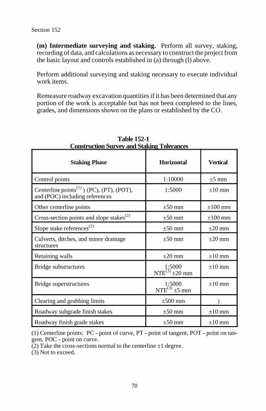
Section 152
70
(m) Intermediate surveying and staking. Perform all survey, staking,recording of data, and calculations as necessary to construct the project fromthe basic layout and controls established in (a) through (l) above.
Perform additional surveying and staking necessary to execute individualwork items.
Remeasure roadway excavation quantities if it has been determined that anyportion of the work is acceptable but has not been completed to the lines,grades, and dimensions shown on the plans or established by the CO.
Table 152-1Construction Survey and Staking Tolerances
Staking Phase Horizontal Vertical
Control points 1:10000 ±5 mm
Centerline points ) (PC), (PT), (POT), 1:5000 ±10 mm(1)
and (POC) including references
Other centerline points ±50 mm ±100 mm
Cross-section points and slope stakes ±50 mm ±100 mm(2)
Slope stake references ±50 mm ±20 mm(2)
Culverts, ditches, and minor drainage ±50 mm ±20 mmstructures
Retaining walls ±20 mm ±10 mm
Bridge substructures 1:5000 ±10 mmNTE ±20 mm(3)
Bridge superstructures 1:5000 ±10 mmNTE ±5 mm(3)
Clearing and grubbing limits ±500 mm )
Roadway subgrade finish stakes ±50 mm ±10 mm
Roadway finish grade stakes ±50 mm ±10 mm
(1) Centerline points: PC - point of curve, PT - point of tangent, POT - point on tan-gent, POC - point on curve.(2) Take the cross-sections normal to the centerline ±1 degree.(3) Not to exceed.
Section 152
71
152.04 Acceptance. Construction survey and staking will be evaluated underSubsections 106.02 and 106.04.
Measurement
152.05 Measure construction survey and staking, bridge survey and staking,and retaining wall survey and staking by the lump sum.
Measure slope, reference, and clearing and grubbing stakes by thekilometer.
Measure centerline reestablishment by the kilometer. Measure centerlinereestablishment only one time.
Measure drainage structure survey and staking by the each.
Measure grade finishing stakes by the kilometer. Measure one time for thesubgrade and one time for each aggregate course.
Measure permanent monuments and markers by the each.
Measure miscellaneous survey and staking by the hour of survey work orderedor by the lump sum. For miscellaneous survey and staking paid by the hour,the minimum survey crew size is 2 persons. Do not measure time spent in mak-ing preparations, traveling to and from the project site, performing calculations,plotting cross-sections and other data, processing computer data, and otherefforts necessary to successfully accomplish construction survey and staking.
Do not measure intermediate surveying and staking for payment.

Section 152
72
Payment
152.06 The accepted quantities, measured as provided above, will be paid atthe contract price per unit of measurement for the pay items listed below thatare shown in the bid schedule. Payment will be full compensation for the workprescribed in this Section. See Subsection 109.05.
The construction survey and staking lump sum item will be paid as follows:
(a) 25 percent of the lump sum, not to exceed 0.5 percent of the original con-tract amount, will be paid following completion of 10 percent of the originalcontract amount not including mobilization and payment for stockpiledmaterial.
(b) Payment of the remaining portion of the lump sum will be prorated basedon the total work completed.
The bridge survey and staking and the retaining wall survey and staking lumpsum items will be paid on a prorated basis as the applicable work progresses.
Payment will be made under:
Pay Item Pay Unit
15201 Construction survey and staking Lump sum15202 Slope, reference, and clearing and grubbing stakes Kilometer15203 Centerline reestablishment Kilometer15204 Drainage structure survey and staking Each15205 Bridge survey and staking Lump sum15206 Retaining wall survey and staking Lump sum15207 Grade finishing stakes Kilometer15208 Permanent monuments and markers Each15209 Miscellaneous survey and staking Hour15210 Miscellaneous survey and staking Lump sum
73
Section 153.) CONTRACTOR QUALITY CONTROL
Description
153.01 This work consists of obtaining samples for Contractor quality controltesting, performing tests for Contractor quality control, providing inspection,and exercising management control to ensure that work conforms to thecontract requirements. This Section supplements FAR Clause 52.246-12,Inspection of Construction.
Construction Requirements
153.02 Contractor Quality Control Plan. Before the start of the work,submit a written quality control plan for acceptance. With prior approval,submission of a quality control plan for items of work not immediatelyscheduled to begin may be deferred.
Submit the following with the quality control plan:
(a) Process control testing. List the material to be tested, tests to beconducted, the location of sampling, and the frequency of testing.
(b) Inspection/control procedures. Address each of the following subjectsin each phase of construction:
(1) Preparatory phase.
(a) Review all contract requirements.(b) Ensure compliance of component material to the contract re-quirements.(c) Coordinate all submittals including certifications.(d) Ensure capability of equipment and personnel to comply with thecontract requirements.(e) Ensure preliminary testing is accomplished.(f) Coordinate surveying and staking of the work.
(2) Start-up phase.
(a) Review the contract requirements with personnel who will performthe work.(b) Inspect start-up of work.(c) Establish standards of workmanship.
Section 153
74
(d) Provide training as necessary.(e) Establish detailed testing schedule based on the productionschedule.
(3) Production phase.
(a) Conduct intermittent or continuous inspection during constructionto identify and correct deficiencies.(b) Inspect completed phases before scheduled Government ac-ceptance.(c) Provide feedback and system changes to prevent repeated defi-ciencies.
(c) Description of records. List the records to be maintained.
(d) Personnel qualifications.
(1) Document the name, authority, relevant experience, and qualificationsof person with overall responsibility for the inspection system.
(2) Document the names, authority, and relevant experience of all person-nel directly responsible for inspection and testing.
(e) Subcontractors. Include the work of all subcontractors. If a subcontrac-tor is to perform work under this Section, detail how that subcontractor willinterface with the Contractor's and/or other subcontractor's organizations.
Modifications or additions may be required to any part of the plan that is notadequately covered. Acceptance of the quality control plan will be based onthe inclusion of the required information. Acceptance does not imply anywarranty by the Government that the plan will result in consistent contractcompliance. It remains the responsibility of the Contractor to demonstrate suchcompliance.
Do not begin the work until the quality control plan covering that work isaccepted.
Supplement the plan as work progresses and whenever quality control orquality control personnel changes are made.
Section 153
75
153.03 Testing. Perform testing according to the accepted quality controlplan. Keep laboratory facilities clean and maintain all equipment in properworking condition. Allow unrestricted access for inspection and review of thefacility.
153.04 Records. Maintain complete testing and inspection records and makethem accessible to the CO.
For each day of work, prepare an "Inspector's Daily Record of ConstructionOperations" (Form FHWA 1413) or an approved alternate form. Include thefollowing certification signed by the person with overall responsibility for theinspection system:
"It is hereby certified that the information contained in this record is accu-rate, and that all work documented herein complies with the requirementsof the contract. Any exceptions to this certification are documented as apart of this record."
Submit the record and certification within one working day of the work beingperformed. If the record is incomplete, in error, or otherwise misleading, acopy of the record will be returned with corrections noted. When chronicerrors or omissions occur, correct the procedures by which the records are pro-duced.
Maintain linear control charts that identify the project number, contract itemnumber, test number, each test parameter, the upper and/or lower specificationlimit applicable to each test parameter, and the test results. Use the controlcharts as part of the quality control system to document the variability of theprocess, to identify production and equipment problems, and to identifypotential pay factor adjustments.
Post control charts in an accessible location and keep them up-to-date. Ceaseproduction and/or make corrections to the process when problems are evident.

Section 153
76
153.05 Acceptance. The Contractor's quality control system will be evaluatedunder Subsection 106.02 based on the demonstrated ability of the qualitycontrol system to result in work meeting the contract requirements.
If the Government's testing and inspection indicate that the Contractor's qualitycontrol system is ineffective, make immediate improvements to the system tocorrect these inadequacies. Furnish notification in writing of improvementsand modifications to the system.
Measurement
153.06 Do not measure Contractor quality control for payment.
77
Section 154. ) CONTRACTORSAMPLING AND TESTING
Description
154.01 This work consists of obtaining samples for testing. When there is acontract pay item for Contractor testing, it also consists of testing and reportingrequired test results. It does not include Contractor quality control testingrequired under Section 153. However, include the work required under thisSection in the Section 153 quality control plan.
Construction Requirements
154.02 Sampling. Sample material to be tested. The sampling schedules andtimes will be provided by the CO using a random number system. In addition,sample any material that appears defective or inconsistent with similar materialbeing produced, unless such material is voluntarily removed and replaced orcorrected.
Sample and split samples according to AASHTO or other acceptable proce-dures. Allow the CO the opportunity to witness all sampling. Immediatelyperform splits when required. Furnish approved containers for the Governm-ent's portion of split samples. Label Government samples. The CO will takepossession of the Government samples.
154.03 Testing. When there is a contract pay item for Contractor testing,perform all tests required by the Sampling and Testing Tables for all applicablework. Allow the CO the opportunity to witness all testing. Testing of trialsamples may be required to demonstrate testing competence.
154.04 Records. Record test results on acceptable forms. Furnish all testresults in the minimum time reasonably necessary to perform the tests andtransmit the results. When tests are on material being incorporated in the work,report test results within 24 hours. Payment for work may be delayed or thework suspended until test results are provided.
154.05 Acceptance. Contractor sampling and testing will be evaluated underSubsections 106.02 and 106.04 based on Government verification testing.

Section 154
78
Measurement
154.06 Measure Contractor testing by the lump sum.
Payment
154.07 The accepted quantity, measured as provided above, will be paid at thecontract price per unit of measurement for the pay item listed below that isshown in the bid schedule. Payment will be full compensation for the workprescribed in this Section. See Subsection 109.05.
The Contractor testing lump sum will be paid as follows:
(a) 25 percent of the lump sum, not to exceed 0.5 percent of the original con-tract amount, will be paid after all the testing facilities are in place, qualifiedsampling and testing personnel are identified, and the work being tested hasstarted.
(b) Payment for the remaining portion of the lump sum will be proratedbased on the total work completed.
Payment for all or part of this item may be retained, if Government verificationtesting invalidates the Contractor testing.
Payment will be made under:
Pay Item Pay Unit
15401 Contractor testing Lump sum

79
Section 155. ) SCHEDULESFOR CONSTRUCTION CONTRACTS
Description
155.01 This work consists of scheduling and monitoring all constructionactivities. This Section supplements FAR Clause 52.236-15, Schedules forConstruction Contracts.
Construction Requirements
155.02 General. Submit 3 copies of a preliminary construction schedule atleast 7 days before the preconstruction conference.
A preliminary construction schedule is a written narrative with a detailedbreakdown of all contract activities for the first 45 days after the notice toproceed is issued. Within 7 days after the preconstruction conference, thepreliminary construction schedule will be accepted or rejected. If rejected,submit a revised schedule within 3 days. Do not begin work, except mobili-zation, traffic control, and Section 637 work, without an accepted preliminaryconstruction schedule.
Use either the Bar Chart Method (BCM) or the Critical Path Method (CPM)described below to develop the construction schedule for the total contractwork. Preface each construction schedule as follows:
(a) Project name(b) Contract number(c) Contractor (d) Original contract time allowed or completion date(e) Type of construction schedule (initial or update) (f) Effective date of the schedule(g) Percent work complete(h) Percent time used
Submit 3 copies of the construction schedule within 30 days after the notice toproceed is issued. Allow 14 days for acceptance or rejection of theconstruction schedule or a revised schedule. If rejected, submit a revisedschedule within 7 days.
Do not show conflicts with any scheduled activities and order of workrequirements in the contract.
Section 155
80
Show completion of the work within the contract time.
155.03 Bar Chart Method (BCM). The BCM construction schedule consistsof a progress bar chart and a written narrative.
(a) Progress bar chart. The following applies to the initial submission andall updates:
(1) Use a time scale to graphically show the percentage of work scheduledfor completion during the contract time.
(2) Define and relate activities to the contract pay items.
(3) Show all activities in the order the work will be performed, includingsubmittals, submittal reviews, fabrication, and delivery.
(4) Show all critical (major) activities that are controlling factors in thecompletion of the work.
(5) Show the time needed to perform each activity and its relationship intime to other activities.
(6) Show the total expected time to complete all work.
(7) Provide enough space for each activity to permit 2 additional plotsparallel to the original time span plot. Use one space for revision of theplanned time span, and one for showing actual time span achieved.
(b) Written narrative. Furnish a written narrative of the activities displayedin the progress bar chart.
155.04 Critical Path Method (CPM). The CPM construction scheduleconsists of a diagram, a tabulated schedule, and a written narrative.
(a) Diagram. Use the "activity-on-arrow" format for the arrow diagrams orthe "activity-on-node" format for precedence diagrams. The followingapplies to the initial submission and all updates:
(1) Use a time scale to graphically show the percent of work scheduled forcompletion by any given date during the contract time.
Section 155
81
(2) Define and relate activities to the contract pay items.
(3) Show the sequence and interdependence of all activities includingsubmittals, submittal reviews, fabrication, and deliveries.
(4) Show all activity nodes, activity descriptions, and durations.
(5) Show all network dummies (for arrow diagrams only).
(6) Identify the critical path.
(b) Tabulated schedule. The following requirements apply to the tabulatedschedule:
(1) For arrow diagrams, show activity beginning and ending nodenumbers. For precedence diagrams, list activities and show lead or lagtimes.
(2) Show activity durations.
(3) Show activity descriptions.
(4) Show early start and finish dates.
(5) Show late start and finish dates.
(6) Show status (critical or not).
(7) Show total float.
(c) Written narrative. Furnish a written narrative of the activities displayedin the schedule diagram.
155.05 Written Narrative. The following applies to the written narrative:
(a) Estimate starting and completion dates of each activity.
(b) Describe work to be done within each activity including the type andquantity of equipment, labor, and material to be used.
(c) Describe the location on the project where each activity occurs.
Section 155
82
(d) Describe planned production rates by pay item quantities (e.g., cubicmeters of excavation per day/week).
(e) Describe work days per week, holidays, number of shifts per day, andnumber of hours per shift.
(f) Estimate any periods during which an activity is idle or partially idle.Show the beginning and end dates for reduced production or idle time.
(g) Describe expected and critical delivery dates for equipment or materialthat can affect timely completion of the project.
(h) Describe critical completion dates for maintaining the construction sche-dule.
(i) Identify the vendor, supplier, or subcontractor to perform the activity.State all assumptions made in the scheduling of the subcontractor's orsupplier's work.
155.06 Schedule Updates. Review the construction schedule to verify finishdates of completed activities, remaining duration of uncompleted activities, andany proposed logic and/or time estimate revisions. Keep the CO informed ofthe current construction schedule and all logic changes.
Submit 3 copies of an updated construction schedule for acceptance at leastevery 8 weeks or when:
(a) A delay occurs in the completion of a critical (major) activity.
(b) A delay occurs which causes a change in the critical path for CPMschedules or a change in a critical activity for BCM schedules.
(c) The actual prosecution of the work is different from that represented onthe current construction schedule.
(d) There is an addition, deletion, or revision of activities caused by acontract modification.
(e) There is a change in the schedule logic.
Section 155
83
155.07 Acceptance. Construction schedules will be evaluated under Sub-section 106.02.
Measurement
155.08 Measure construction schedules by the lump sum.
Payment
155.09 The accepted quantity, measured as provided above, will be paid at thecontract price per unit of measurement for the pay item listed below that isshown in the bid schedule. Payment will be full compensation for the workprescribed in this Section. See Subsection 109.05.
The construction schedule lump sum will be paid as follows:
(a) 25 percent of the lump sum, not to exceed 0.5 percent of the originalcontract amount, will be paid after the preliminary construction schedule isaccepted.
(b) 50 percent of the lump sum will be paid after the construction scheduleis accepted.
(c) Payment of the remaining portion of the lump sum will be prorated basedon the total work completed.
Payment will be made under:
Pay Item Pay Unit
15501 Construction schedule Lump sum
84
Section 156.) PUBLIC TRAFFIC
Description
156.01 This work consists of controlling and protecting public traffic adjacentto and within the project. This section supplements FAR Clause 52.236-13,Accident Prevention.
Material
156.02 Conform to the following Section:
Temporary traffic control 635
Construction Requirements
156.03 Accommodating Traffic During Work. Accommodate trafficaccording to the contract traffic control plan, MUTCD, Section 635, and thisSection. The Contractor may submit an alternate traffic control proposal.Submit alternate traffic control proposals according to Subsection 104.03 foracceptance at least 30 days before intended use.
Perform work in a manner that assures the safety and convenience of the publicand protects the residents and property adjacent to the project. Accommodatepublic traffic on roads adjacent to and within the project until the project isaccepted according to Subsection 106.07(b).
156.04 Maintaining Roadways During Work. Perform roadway mainte-nance as follows:
(a) Construct and remove detour roads and bridges as required by the trafficcontrol plan.
(b) Maintain intersections with trails, roads, streets, businesses, parking lots,residences, garages, farms, and other features.
(c) Provide access for snow removal by others.
(d) Maintain a reasonably dust-free traveled way.
(e) Remove accumulations of soil and other material from traveled way.
Section 156
85
Maintain the roadway and detours in a safe and acceptable condition. Ifcorrective action is requested and the corrective action is not taken immedi-ately, the condition may be corrected and the cost of the corrective actiondeducted from monies due the Contractor.
156.05 Maintaining Roadways During Non-Work Periods. Maintainroadways and traffic control for public traffic during all periods when work isnot in progress. The Government is responsible for snow removal.
156.06 Limitations on Construction Operations. When the roadway is opento public traffic, restrict operations as follows:
(a) Operate equipment in the direction of traffic, where practical.
(b) Install permanent traffic barriers within 30 days of completing the surfacecourse.
(c) For shoulder drop-offs in excess of 50 millimeters, provide "Low Shoul-der" warning signs. For shoulder drop-offs in excess of 100 millimeters,provide a 1:3 fillet with "Low Shoulder" warning signs. Complete the con-struction of shoulders adjacent to traffic lanes to the same elevation within14 days.
(d) Provide minimum lane widths of 3.0 meters. Use barricades, drums, orother acceptable devices to delineate traffic lanes through areas where theedge of pavement or intended path has been obliterated by constructionoperations.
(e) Locate staging areas at least 10 meters from the traveled way or behindacceptable traffic barriers. Obtain approval of the location and access tostaging areas. Store unused traffic control devices at staging areas.
(f) Park equipment at least 10 meters from the traveled way or behind ac-ceptable traffic barriers.
(g) Provide parking areas for employees' personal vehicles in approved areas.
Section 156
86
(h) Provide two-way radio communications between flaggers and betweenflaggers and pilot cars unless flaggers are able to see each other andcommunicate. Citizen band radios are not acceptable. Make radio equip-ment available to the CO as necessary.
(i) Where switching traffic to a completed lane, provide adequate personneland equipment to set or relocate traffic control devices.
(j) Limit construction caused delays to public traffic to a maximum of 30minutes per passage through the project.
156.07 Nighttime Operations. Perform construction operations during thehours of daylight (½ hour after sunrise to ½ hour before sunset). Where night operations are permitted, submit a night lighting system forapproval. Include the light types, locations, and the manner in which the lightswill be moved. Submit the proposed system at least 14 days before use. Usean independent source other than vehicle headlights. Do not use incandescentlights. Furnish and install the approved system to illuminate the entire workarea. Position the lights so they do not shine directly at motorists travelingfrom any direction. If the operation is moving, move the lighting with theoperation. Provide lighting at each flagger location. Equip all vehicles withan exterior flashing yellow dome light.
156.08 Traffic and Safety Supervisor. Provide a traffic and safety super-visor who is certified by a state highway agency or other acceptable certifica-tion program. Do not designate the superintendent as the traffic safetysupervisor. Furnish the traffic safety supervisor's name, address, and 24-hourtelephone number(s) at the preconstruction conference. At all times during thecontract, including periods of suspensions and work stoppages, perform all ofthe following:
(a) Implement the traffic control plans.(b) Coordinate traffic control operations, including those of subcontractorsand suppliers.(c) Ensure the condition, position, and applicability of traffic control devicesin use.(d) Immediately correct traffic control deficiencies.(e) Coordinate traffic control maintenance operations with the CO.(f) Ensure unused traffic control devices are properly handled and stored.
Section 156
87
(g) Conduct weekly traffic safety meetings for construction workers andinvite the CO to these weekly meetings.(h) Furnish a weekly certification that inspections and reviews were con-ducted and that the traffic control devices meet contract requirements.Include the number and types of devices in use. Report with the weeklycertification, all changes or corrective actions taken to ensure the safepassage of public traffic through the project.
156.09 Acceptance. Public traffic work will be evaluated under Subsec-tion 106.02.
Traffic control devices and services will be evaluated under Section 635.
Measurement and Payment
156.10 See Subsection 109.05.
Measure traffic control under Section 635.
Measure dust abatement under Section 158 or 306.
Measure detour construction, when required by the contract, under theapplicable pay items.
88
Section 157.) SOIL EROSION CONTROL
Description
157.01 This work consists of furnishing, constructing, and maintaining perma-nent and temporary erosion and sediment control measures.
Material
157.02 Conform to the following Subsections:
Backfill material 704.03Bales 713.13Erosion control culvert pipe 713.15Fertilizer 713.03Geotextile 714.01Matting 629.02Mulch 713.05Plastic lining 725.19Riprap 251.02Sandbags 713.14Seed 713.04Silt fence 713.16Water 725.01
Construction Requirements
157.03 General. Provide permanent and temporary erosion control measuresto minimize erosion and sedimentation during and after construction accordingto the contract erosion control plan, contract permits, Section 107, and thisSection. Contract permits amend the requirements of this Section. Do notmodify the type, size, or location of any control or practice without approval.
The contract erosion control plan reflects special concerns and measures toprotect resources. An alternate erosion control proposal, with all necessarypermits, may be submitted for approval according to Subsection 104.03. Sub-mit alternate erosion control proposals at least 30 days before their intendeduse.
Section 157
89
When erosion control measures are not functioning as intended, immediatelytake corrective action.
157.04 Controls and Limitations on Work. Before grubbing and grading,construct all erosion controls around the perimeter of the project includingfilter barriers, diversion, and settling structures.
Limit the combined grubbing and grading operations area to 30 000 squaremeters of exposed soil at one time.
Construct erosion control and sediment control measures as follows:
(a) Construct temporary erosion controls in incremental stages as construc-tion proceeds.
(b) Construct temporary slope drains, diversion channels, and earth berms toprotect disturbed areas and slopes.
(c) Unless a specific seeding season is identified in the contract, apply per-manent turf establishment to the finished slopes and ditches within 30 daysaccording to Sections 624 and 625.
(d) Apply temporary turf establishment or other approved measures ondisturbed areas that will remain exposed for over 30 days.
(e) Construct outlet protection as soon as culverts or other structures arecomplete.
(f) Construct permanent erosion controls including waterway linings andslope treatments as soon as practical or upon completion of the roadbed.
(g) Construct and maintain erosion controls on and around soil stockpiles toprevent soil loss.
(h) Following each day's grading operations, shape earthwork to minimizeand control erosion from storm runoff.
Section 157
90
157.05 Filter Barriers. Construct silt fence, bales, and brush barriers forfiltering sediment from runoff and reducing the velocity of sheet flow.Conserve brush from clearing operations to construct brush barriers.
157.06 Sediment Retention Structures. Construct sediment retentionstructures of the following types:
(a) Temporary sediment traps. Construct temporary sediment traps todetain runoff from disturbed areas and settle out sediment. Provide outletprotection.
(b) Sediment basins. Construct sediment basins to store runoff and settleout sediment for large drainage areas. Construct sediment basins accordingto Section 204. Construct riser pipes according to Section 602. Provideoutlet protection.
157.07 Outlet Protection. Construct riprap aprons or basins to reduce watervelocity and prevent scour at the outlet of permanent and temporary erosioncontrol measures. Construct riprap according to Section 251.
157.08 Water Crossings. Construct temporary culvert pipe at temporarycrossings where construction vehicles cross a live waterway.
157.09 Diversions. Construct temporary channels, temporary culverts, earthberms, or sandbags to divert water around disturbed areas and slopes. Usetemporary channels, temporary culverts, pumps, sandbags, or other methods todivert the flow of live streams for permanent culvert installations and otherwork. Stabilize channels according to Subsection 157.10. Provide outletprotection.
157.10 Waterway and Slope Protection and Stabilization. Use plasticlining, riprap, check dams, erosion control blankets and mats, and tempo-rary slope drains as follows:
(a) Plastic lining. Use plastic lining to protect underlying soil from erosion.Place the plastic lining loosely on a smooth soil surface free of projectionsor depressions that may cause the liner to puncture or tear. Lap transversejoints a minimum of 1 meter in the direction of flow. Do not use longitudinaljoints. Anchor the lining in place using riprap.
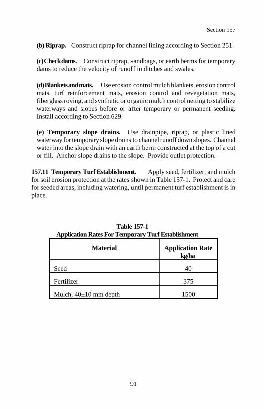
Section 157
91
(b) Riprap. Construct riprap for channel lining according to Section 251.
(c) Check dams. Construct riprap, sandbags, or earth berms for temporarydams to reduce the velocity of runoff in ditches and swales.
(d) Blankets and mats. Use erosion control mulch blankets, erosion controlmats, turf reinforcement mats, erosion control and revegetation mats,fiberglass roving, and synthetic or organic mulch control netting to stabilizewaterways and slopes before or after temporary or permanent seeding.Install according to Section 629.
(e) Temporary slope drains. Use drainpipe, riprap, or plastic linedwaterway for temporary slope drains to channel runoff down slopes. Channelwater into the slope drain with an earth berm constructed at the top of a cutor fill. Anchor slope drains to the slope. Provide outlet protection.
157.11 Temporary Turf Establishment. Apply seed, fertilizer, and mulchfor soil erosion protection at the rates shown in Table 157-1. Protect and carefor seeded areas, including watering, until permanent turf establishment is inplace.
Table 157-1Application Rates For Temporary Turf Establishment
Material Application Ratekg/ha
Seed 40
Fertilizer 375
Mulch, 40±10 mm depth 1500
Section 157
92
157.12 Inspection and Reporting. Inspect all erosion control facilities atleast every 7 days, within 24 hours after more than 10 millimeters of rain in a24-hour period, and as required by the contract permits.
Within 24 hours, furnish inspection reports to the CO which include all of thefollowing:
(a) Summary of the inspection(b) Names of personnel making the inspection(c) Date and time of inspection(d) Observations made(e) Corrective action necessary, action taken, and date and time of action
157.13 Maintenance and Cleanup. Maintain temporary erosion controlmeasures in working condition until the project is complete or the measures areno longer needed. Clean erosion control measures when half full of sediment.Use the sediment in the work, if acceptable, or dispose of it according toSubsection 204.14.
Replace erosion control measures that cannot be maintained and those that aredamaged by construction operations.
Remove and dispose of temporary erosion control measures when the turf issatisfactorily established and drainage ditches and channels are lined andstabilized. Remove and dispose of erosion control measures according toSubsection 203.05.
Restore the ground to its natural or intended condition and provide permanenterosion control measures.
157.14 Acceptance. Material for soil erosion control measures will beevaluated under Subsections 106.02 and 106.03.
Construction, maintenance, and removal of soil erosion control measures willbe evaluated under Subsections 106.02 and 106.04.
Geotextile will be evaluated under Section 207.
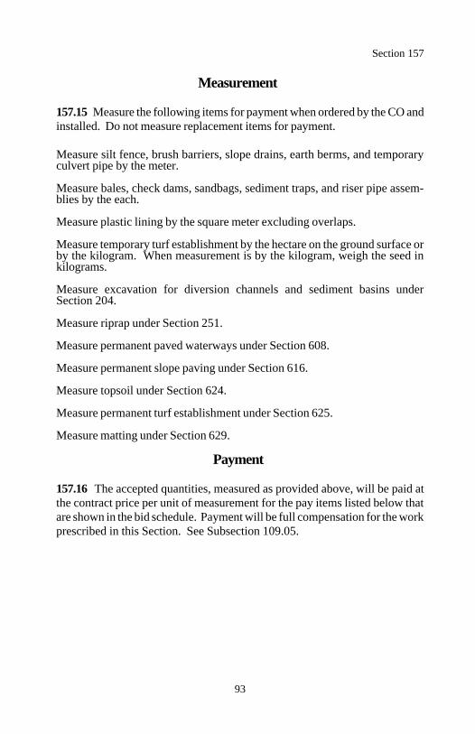
Section 157
93
Measurement
157.15 Measure the following items for payment when ordered by the CO andinstalled. Do not measure replacement items for payment.
Measure silt fence, brush barriers, slope drains, earth berms, and temporaryculvert pipe by the meter.
Measure bales, check dams, sandbags, sediment traps, and riser pipe assem-blies by the each.
Measure plastic lining by the square meter excluding overlaps.
Measure temporary turf establishment by the hectare on the ground surface orby the kilogram. When measurement is by the kilogram, weigh the seed inkilograms.
Measure excavation for diversion channels and sediment basins underSection 204.
Measure riprap under Section 251.
Measure permanent paved waterways under Section 608.
Measure permanent slope paving under Section 616.
Measure topsoil under Section 624.
Measure permanent turf establishment under Section 625.
Measure matting under Section 629.
Payment
157.16 The accepted quantities, measured as provided above, will be paid atthe contract price per unit of measurement for the pay items listed below thatare shown in the bid schedule. Payment will be full compensation for the workprescribed in this Section. See Subsection 109.05.
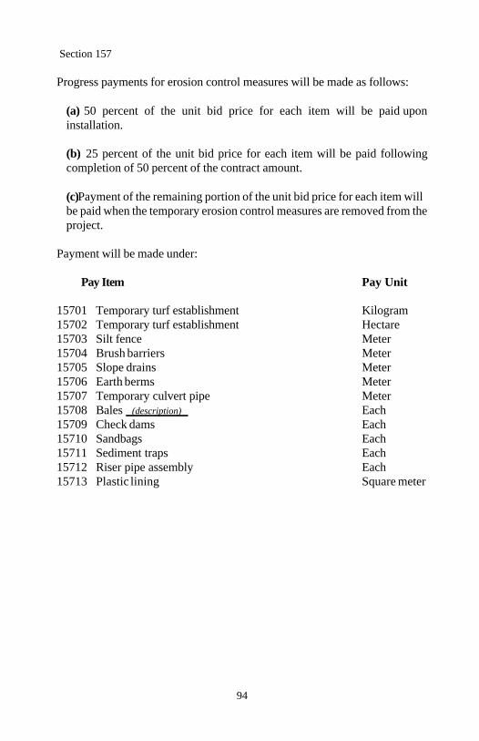
Section 157
94
Progress payments for erosion control measures will be made as follows:
(a) 50 percent of the unit bid price for each item will be paid uponinstallation.
(b) 25 percent of the unit bid price for each item will be paid followingcompletion of 50 percent of the contract amount.
(c) Payment of the remaining portion of the unit bid price for each item willbe paid when the temporary erosion control measures are removed from theproject.
Payment will be made under:
Pay Item Pay Unit
15701 Temporary turf establishment Kilogram15702 Temporary turf establishment Hectare15703 Silt fence Meter15704 Brush barriers Meter15705 Slope drains Meter15706 Earth berms Meter15707 Temporary culvert pipe Meter15708 Bales (description) Each15709 Check dams Each15710 Sandbags Each15711 Sediment traps Each15712 Riser pipe assembly Each15713 Plastic lining Square meter
95
Section 158.) WATERING FOR DUST CONTROL
Description
158.01 This work consists of furnishing and applying water for the control ofdust caused by the work and public travel.
Material
158.02 Conform to the following Subsection:
Water 725.01
Construction Requirements
158.03 General. Provide an adequate water supply and apply water neededat all hours (including nights, weekends, and periods of nonwork) as necessaryto control dust. Uniformly apply water using pressure-type distributors, pipe-lines equipped with spray systems, or hoses with nozzles.
(a) Project dust control for public benefit. Control dust within theconstruction limits at all hours when the project is open to public traffic.When the project is not open to public traffic, control dust in areas of theproject which neighbor inhabited residences or places of business. Controldust on approved, active detours established for the project. Apply water atthe locations, rates, and frequencies ordered by the CO.
(b) Other dust control. Control dust on active haul roads, in pits andstaging areas, and on the project during all periods not covered in (a) above.
158.04 Acceptance. Furnishing and placing water will be evaluated underSubsection 106.02.
Measurement
158.05 When applied according to Subsection 158.03(a), measure watering fordust control by the cubic meter in the hauling vehicle or by metering. Do notmeasure water applied according to Subsection 158.03(b) for payment.

Section 158
96
Payment
158.06 The accepted quantities, measured as provided above, will be paid atthe contract price per unit of measurement for the pay item listed below that isshown in the bid schedule. Payment will be full compensation for the workprescribed in this Section. See Subsection 109.05.
Payment will be made under:
Pay Item Pay Unit
15801 Watering for dust control Cubic meter
97
DIVISION 200Earthwork
98
Section 201.) CLEARING AND GRUBBING
Description
201.01 This work consists of clearing and grubbing within the clearing limitsdesignated on the plans.
Material
201.02 Conform to the following Subsections:
Backfill material 704.03Tree wound dressing 713.08(g)
Construction Requirements
201.03 General. Construct erosion control measures according to Section 157. Perform work within designated limits. Do not damage vegetationdesignated to remain. If vegetation designated to remain is damaged ordestroyed, repair or replace the vegetation in an acceptable manner. Wherepossible, preserve all vegetation adjacent to bodies of water. Treat cuts orscarred surfaces of trees and shrubs with tree wound dressing.
201.04 Clearing. Within the clearing limits, clear trees, brush, downedtimber, and other vegetation as follows:
(a) Cut all trees so they fall within the clearing limits.
(b) In areas of cut slope rounding, cut stumps flush with or below the finalgroundline.
(c) In areas outside the excavation, embankment, and slope rounding limits,cut stumps to within 150 millimeters of the ground.
(d) Trim tree branches that extend over the road surface and shoulders toattain a clear height of 6 meters. If required, remove other branches topresent a balanced appearance. Trim according to accepted tree surgerypractices. Treat wounds with tree wound dressing.
Section 201
99
201.05 Grubbing. Grub deep enough to remove stumps, roots, buried logs,moss, turf, or other vegetative debris as follows:
(a) Grub all areas to be excavated, except for cut slope rounding areas.
(b) Grub all embankment areas, except that undisturbed stumps protrudingless than 150 millimeters above the original ground and covered with aminimum of 1 meter of embankment may be left in place.
(c) Grub pits, channel changes, and ditches only to the depth necessary forthe excavation.
(d) Backfill stump holes and other grubbing holes with backfill material tothe level of the surrounding ground according to Subsection 209.10.Compact backfill according to Subsection 209.11.
201.06 Disposal. Merchantable timber is the Contractor's property. Disposeof clearing and grubbing debris according to Subsection 203.05.
201.07 Acceptance. Clearing and grubbing will be evaluated for underSubsection 106.02.
Material for tree wound dressing will be evaluated under Subsection 106.03.
Backfilling and compacting of stumps and grubbing holes will be evaluatedunder Section 209.
Measurement
201.08 Measure clearing and grubbing by the hectare or by the lump sum. Donot make deductions from the area computation unless excluded areas areidentified in the contract.
Do not measure clearing and grubbing of borrow or material sources forpayment.

Section 201
100
Payment
201.09 The accepted quantity, measured as provided above, will be paid at thecontract price per unit of measurement for the pay items listed below that areshown in the bid schedule. Payment will be full compensation for the workprescribed in this Section. See Subsection 109.05.
Payment will be made under:
Pay Item Pay Unit
20101 Clearing and grubbing Hectare20102 Clearing and grubbing Lump sum
101
Section 202.) ADDITIONALCLEARING AND GRUBBING
Description
202.01 This work consists of clearing and grubbing outside the clearing limitsspecified in Section 201. It includes scalloping clearing lines, clearing vistas,thinning vegetation, special clearing and grubbing, and the removal of indi-vidual trees and stumps.
202.02 Definitions.
(a) Selective clearing. Clearing where some trees and/or other vegetationis designated to remain.
(b) Selective clearing and grubbing. Clearing and grubbing where sometrees and/or vegetation is designated to remain.
(c) Special clearing and grubbing. Clearing and grubbing where all treesand/or vegetation are removed.
(d) Removal of individual trees or stumps. Removing individual trees orstumps outside the clearing limits designated in Section 201 or outside areasdesignated in (a) through (c) above.
Construction Requirements
202.03 General. Clear and grub according to Section 201 except as modifiedherein. Do not push, pull, or fall trees into trees designated to remain. Removedesignated debris by methods that prevent damage to vegetation not designatedto be removed. Dispose of clearing and grubbing debris according toSubsection 203.05.
202.04 Selective Clearing. Clear and dispose of all trees, snags, brush,downed timber, and other vegetation designated to be removed.
202.05 Selective Clearing and Grubbing. Clear, grub, and dispose of alltrees, snags, brush, downed timber, stumps, roots, buried logs, moss, turf,grass, and other vegetation designated to be removed.
Section 202
102
202.06 Special Clearing and Grubbing. Clear, grub, and dispose of all trees,snags, brush, downed timber, stumps, roots, buried logs, moss, turf, grass, andother vegetation.
202.07 Removal of Individual Trees or Stumps. Remove and dispose of alldesignated trees or stumps.
202.08 Acceptance. Additional clearing and grubbing work will be evaluatedunder Subsection 106.02 and Section 201.
Measurement
202.09 Measure selective clearing, selective clearing and grubbing, andspecial clearing and grubbing by the hectare.
Measure removal of individual trees by the square meter based on the averagediameter at the cutoff. Do not measure trees less than 150 millimeters indiameter at the cutoff for payment.
Measure removal of individual stumps by the each.
Payment
202.10 The accepted quantity, measured as provided above, will be paid at thecontract price per unit of measurement for the pay items listed below that areshown in the bid schedule. Payment will be full compensation for the workprescribed in this Section. See Subsection 109.05.
Payment will be made under:
Pay Item Pay Unit
20201 Selective clearing Hectare20202 Selective clearing and grubbing Hectare20203 Special clearing and grubbing Hectare20204 Removal of individual trees Square meter20205 Removal of individual stumps Each
103
Section 203.) REMOVAL OF STRUCTURESAND OBSTRUCTIONS
Description
203.01 This work consists of salvaging, removing, and disposing of buildings,fences, structures, pavements, culverts, utilities, curbs, sidewalks, and other ob-structions.
Material
203.02 Conform to the following Section and Subsection:
Backfill material 704.03Concrete 601
Construction Requirements
203.03 Salvaging Material. Salvage, with reasonable care, all materialdesignated to be salvaged. Salvage in readily transportable sections or pieces.Replace or repair all members, pins, nuts, plates, and related hardwaredamaged, lost, or destroyed during the salvage operation. Wire all loose partsto adjacent members or pack them in sturdy boxes with the contents clearlymarked.
Matchmark members of salvaged structures. Furnish one set of drawingsidentifying the members and their respective matchmarks.
Stockpile salvaged material at a designated area on the project.
203.04 Removing Material. Saw cut sidewalks, curbs, pavements, andstructures when partial removal is required.
Construct structurally adequate debris shields to contain debris within theconstruction limits. Do not permit debris to enter waterways, travel lanes opento public traffic, or areas designated not to be disturbed.
Raze and remove all buildings, foundations, pavements, sidewalks, curbs,fences, structures, and other obstructions interfering with the work and notdesignated to remain.
Section 203
104
Where part of an existing culvert is removed, remove all of the culvert up-stream from the removal. The remaining downstream culvert may be left inplace if no portion of the culvert is within 1 meter of the subgrade, em-bankment slope, or new culvert or structure; and the culvert ends are sealedwith concrete.
Remove structures and obstructions in the roadbed to 1 meter below subgradeelevation. Remove structures and obstructions outside the roadbed to 0.5 meterbelow finished ground or to the natural stream bottom.
Abandon existing manholes, inlets, catch basins, and spring boxes accordingto Subsection 604.07.
Except in excavation areas, backfill and compact cavities left by structureremoval with backfill material to the level of the finished ground. Backfillexcavated areas according to Subsection 209.10. Compact backfill accordingto Subsection 209.11.
203.05 Disposing of Material. Where economically and practically feasible,the Contractor is urged to recycle material. Dispose of debris and unsuitableand excess material as follows:
(a) Remove from project. Recycle or dispose of material legally off theproject. Furnish a statement documenting the nature and quantity of materialprocessed or sold for recycling. Otherwise, furnish a signed copy of thedisposal agreement before disposal begins.
(b) Burn. Obtain necessary burning permits. Furnish a copy of the burningpermits before burning begins.
Burn using high intensity burning processes that produce few emissions.Examples include incinerators, high stacking, or pit and ditch burning withforced air supplements. Provide a competent watchperson during the burningoperations.
When burning is complete, extinguish the fire so no smoldering debris re-mains. Dispose of unburned material according to (a) above.
(c) Bury. Bury debris in trenches or pits in approved areas within the right-of-way. Do not bury debris inside the roadway prism limits, beneath drain-age ditches, or in any areas subject to free-flowing water.
Section 203
105
Place debris in alternating layers with earth material. Alternating layersconsist of 1 meter of debris covered with 0.5 meter of earth. Distributestumps, logs, and other large pieces to form a dense mass and minimize airvoids. Fill all voids. Cover the top layer of buried debris with at least 0.5meter of compacted earth. Grade and shape the area.
(d) Hazardous material. Furnish a copy of all disposal permits. Disposeof material according to Federal, state, and local regulations.
203.06 Acceptance. Removal of structures and obstructions will be evaluatedunder Subsection 106.02.
Backfilling and compacting cavities left by structures will be evaluated underSection 209.
Concrete will be evaluated under Section 601.
Measurement
203.07 Measure removal of structures and obstructions by the each, by themeter, by the square meter, or by the lump sum. Measure removal by the meterand by the square meter before removal.
Payment
203.08 The accepted quantities, measured as provided above, will be paid atthe contract price per unit of measurement for the pay items listed below thatare shown in the bid schedule. Payment will be full compensation for the workprescribed in this Section. See Subsection 109.05.
Payment will be made under:
Pay Item Pay Unit
20301 Removal (description) Each20302 Removal (description) Meter20303 Removal (description) Square meter20304 Removal (description) Lump sum20305 Removal of structures and obstructions Lump sum
106
Section 204.) EXCAVATION AND EMBANKMENT
Description
204.01 This work consists of excavating material and constructing embank-ments. This includes furnishing, hauling, stockpiling, placing, disposing,sloping, shaping, compacting, and finishing earthen and rocky material.
204.02 Definitions.
(a) Excavation. Excavation consists of the following:
(1) Roadway excavation. All material excavated from within the right-of-way or easement areas, except subexcavation covered in (2) below andstructure excavation covered in Sections 208 and 209. Roadway exca-vation includes all material encountered regardless of its nature orcharacteristics.
(2) Subexcavation. Material excavated from below subgrade elevationin cut sections or from below the original groundline in embankmentsections. Subexcavation does not include the work required by Subsec-tions 204.05, 204.06(b), and 204.06(c).
(3) Borrow excavation. Material used for embankment construction thatis obtained from outside the roadway prism. Borrow excavation includesunclassified borrow, select borrow, and select topping.
(b) Embankment construction. Embankment construction consists of theplacement and compaction of roadway or borrow excavation. This work in-cludes:
(1) Preparing foundation for embankment(2) Constructing roadway embankments(3) Benching for side-hill embankments(4) Constructing dikes, ramps, mounds, and berms(5) Backfilling subexcavated areas, holes, pits, and other depressions
(c) Embankment material. Material for embankment construction are:
(1) Rock. Rock is material containing 25 percent or more, by volume,rock particles greater than 100 millimeters in diameter.
Section 204
107
(2) Earth. Earth is material containing less than 25 percent, by volume,rock particles greater than 100 millimeters in diameter.
(d) Conserved topsoil. Excavated material conserved from the roadwayexcavation and embankment foundation areas that is suitable for growth ofgrass, cover crops, or native vegetation. A material reasonably free fromhard soil, rock, clay, toxic substances, litter, or other deleterious material.
(e) Waste. Excess and unsuitable roadway excavation and subexcavationthat cannot be used.
Material
204.03 Conform to the following Subsections:
Backfill material 704.03Select borrow 704.07Select topping 704.08Topping 704.05Unclassified borrow 704.06Water 725.01
Construction Requirements
204.04 Preparation for Roadway Excavation and Embankment Con-struction. Clear the area of vegetation and obstructions according to Sections201 and 203.
204.05 Conserved Topsoil . Conserve topsoil from roadway excavation andembankment foundation areas. Stockpile conserved topsoil in low windrowsimmediately beyond the rounding limits of cut and embankment slopes or inother approved locations. Separate topsoil from other excavated material.
Place conserved topsoil on completed slopes according to Section 624.
Section 204
108
204.06 Roadway Excavation. Excavate as follows:
(a) General. Do not disturb material and vegetation outside the constructionlimits.
Excavate material suitable for backfill, roadbed finishing, topping, or otherpurposes in a sequence that permits the placement of the excavation directlyinto its final position or in stockpiles for subsequent placing.
Incorporate only suitable material into embankments. Replace any shortageof suitable material caused by premature disposal of roadway excavation.Dispose of unsuitable or excess excavation material according to Subsection204.14.
At the end of each day's operations, shape to drain and compact the workarea to a uniform cross-section. Eliminate all ruts and low spots that couldhold water.
(b) Rock cuts. Blast rock according to Section 205. Excavate rock cuts to150 millimeters below subgrade within the roadbed limits. Backfill to sub-grade with topping or with other suitable material. Compact the materialaccording to Subsection 204.11.
(c) Earth cuts. Scarify earth cuts to 150 millimeters below subgrade withinthe roadbed limits. Compact the scarified material according to Subsection204.11.
204.07 Subexcavation. Excavate material to the limits designated by the CO.Where applicable, survey cross-sections according to Section 152. Preventunsuitable material from becoming mixed with the backfill. Dispose ofunsuitable material according to Subsection 204.14. Backfill thesubexcavation with topping, or other suitable material. Compact the materialaccording to Subsection 204.11.
204.08 Borrow Excavation. Use all suitable roadway excavation in em-bankment construction. Do not use borrow excavation when it results in excessroadway excavation. Excess borrow excavation will be deducted from theappropriate borrow excavation quantity.
Section 204
109
Obtain borrow source acceptance according to Subsection 105.02. Developand restore borrow sources according to Subsection 105.03. Do not excavatebeyond the established limits. When applicable, shape the borrow source topermit accurate measurements when excavation is complete.
204.09 Preparing Foundation for Embankment Construction. Preparefoundation for embankment construction as follows:
(a) Embankment less than 1 meter high over natural ground. Complete-ly break up the cleared ground surface to a minimum depth of 150 milli-meters by plowing or scarifying. Compact the ground surface according toSubsection 204.11.
(b) Embankment less than 0.5 meter high over an existing asphalt, con-crete, or gravel road surface. Scarify gravel roads to a minimum depth of150 millimeters. Scarify or pulverize asphalt and concrete roads to 150millimeters below the pavement. Reduce all particles to a maximum size of150 millimeters and produce a uniform material. Compact the surface ac-cording to Subsection 204.11.
(c) Embankment across ground not capable of supporting equipment.Dump successive loads of embankment material in a uniformly distributedlayer to construct the lower portion of the embankment. Limit the layerthickness to the minimum depth necessary to support the equipment.
(d) Embankment on an existing slope steeper than 1:3 (1 unit vertical to3 units horizontal). Cut horizontal benches in the existing slope to asufficient width to accommodate placement and compaction operations andequipment. Bench the slope as the embankment is placed and compacted inlayers. Begin each bench at the intersection of the original ground and thevertical cut of the previous bench.
204.10 Embankment Construction. Incorporate only suitable roadwayexcavation material into the embankment. When the supply of suitableroadway excavation is exhausted, furnish unclassified borrow to complete theembankment. Construct embankments as follows:
(a) General. At the end of each day's operations, shape to drain andcompact the embankment surface to a uniform cross-section. Eliminate allruts and low spots that could hold water.
Section 204
110
During all stages of construction, route and distribute hauling and levelingequipment over the width and length of each layer of material.
Compact embankment side slopes with a tamping type roller or by walkingwith a dozer. For slopes 1:1.75 or steeper, compact the slopes as con-struction of the embankment progresses.
(b) Rock. Place rock in horizontal layers not exceeding 300 millimeters incompacted thickness. Material composed predominantly of boulders or rockfragments too large for 300-millimeter layers may be placed in layers of upto 600 millimeters thick. Incorporate oversize boulders or rock fragmentsinto a 600-millimeter layer by reducing them in size or placing themindividually according to (c) below. Place rock layers with sufficient earthand smaller rocks to fill the voids. Compact each layer according to Subsec-tion 204.11 before placing the next layer.
Construct the top 300 millimeters of the embankment with topping or othersuitable material.
(c) Individual rock fragments and boulders. Place individual rockfragments and boulders greater than 600 millimeters in diameter as fol-lows:
(1) Reduce rock to less than 1200 millimeters in the largest dimension.
(2) Distribute rock within the embankment to prevent nesting and fill thevoids between them with finer material.
(3) Compact each layer according to Subsection 204.11.
(d) Earth. Place earth in horizontal layers not exceeding 300 millimeters incompacted thickness. Incorporate oversize boulders or rock fragments intothe 300-millimeter layers by reducing them in size or placing them individu-ally as required in (c) above.
Compact each layer according to Subsection 204.11 before placing the nextlayer.
Section 204
111
(e) Embankment outside of roadway prism. Where placing embankmentoutside the staked roadway prism, place material in horizontal layers notexceeding 600 millimeters in compacted thickness. Compact each layeraccording to Subsection 204.11(a).
(f) Other Embankments. Where placing embankment on one side ofabutments, wing walls, piers, or culvert headwalls, compact the materialusing methods that prevent excessive pressure against the structure.
Where placing embankment material on both sides of a concrete wall or boxstructure, conduct operations so compacted embankment material is at thesame elevation on both sides of the structure.
Where structural pilings are placed in embankment locations, limit themaximum particle size to 100 millimeters.
204.11 Compaction. Compact as follows:
(a) Rock embankment. Adjust the moisture content of the material to amoisture content suitable for compaction. Compact each layer of materialfull width with one of the following:
(1) Four roller passes of a 45-metric ton compression-type roller(2) Four roller passes of a vibratory roller having a minimum dynamic force of 180 kilonewtons impact per vibration and a minimum frequency of 16 hertz
(3) Eight roller passes of a 20-metric ton compression-type roller(4) Eight roller passes of a vibratory roller having a minimum dynamicforce of 130 kilonewtons impact per vibration and a minimum
frequency of 16 hertz
Proportion the compactive effort for layers deeper than 300 millimeters asfollows.
For each additional 150 millimeters or fraction thereof, increase thenumber of roller passes in (1) and (2) above by four. For each additional 150 millimeters or fraction thereof, increase the
number of roller passes in (3) and (4) above, by eight.
Section 204
112
Operate compression-type rollers at speeds less than 2 meters per second andvibratory rollers at speeds less than 1 meter per second.
(b) Earth embankment. Classify the material according to AASHTOM 145. For material classified A-1 or A-2-4, determine the maximum densi-ty according to AASHTO T 180 method D. For other material classifi-cations, determine the optimum moisture content and maximum densityaccording to AASHTO T 99 method C.
Adjust the moisture content of material classified A-1 through A-5 to amoisture content suitable for compaction. Adjust the moisture content ofmaterial classified A-6 and A-7 to within 2 percent of the optimum moisturecontent.
Compact material placed in all embankment layers and the material scarifiedin cut sections to at least 95 percent of the maximum density. Determine theinplace density and moisture content according to AASHTO T 238 andAASHTO T 239 or other approved test procedures.
204.12 Ditches. Slope, grade, and shape ditches. Remove all projectingroots, stumps, rock, or similar matter. Maintain all ditches in an opencondition and free from leaves, sticks, and other debris.
Form furrow ditches by plowing or using other acceptable methods to producea continuous furrow. Place all excavated material on the downhill side so thebottom of the ditch is approximately 0.5 meter below the crest of the loosematerial. Clean the ditch using a hand shovel, ditcher, or other suitable meth-od. Shape to provide drainage without overflow.
204.13 Sloping, Shaping, and Finishing. Complete slopes, ditches, culverts,riprap, and other underground minor structures before placing aggregate cours-es. Slope, shape, and finish as follows:
(a) Sloping. Leave all earth slopes with uniform roughened surfaces, exceptas described in (b) below, with no noticeable break as viewed from the road.Except in solid rock, round tops and bottoms of all slopes, including theslopes of drainage ditches. Round material overlaying solid rock to theextent practical. Scale all rock slopes.
Section 204
113
If a slide or slipout occurs on a cut or embankment slope, remove or replacethe material and repair or restore all damage to the work. Bench or key theslope to stabilize the slide. Reshape the cut or embankment slope to anacceptable condition.
(b) Stepped slopes. Where required by the contract, construct steps onslopes of 1.3:1 to 1:2. Construct the steps approximately 0.5 meter high.Blend the steps into natural ground at the end of the cut. If the slope containsnonrippable rock outcrops, blend steps into the rock. Remove loose materialfound in transitional area. Except for removing large rocks that may fall,scaling stepped slopes is not required.
(c) Shaping. Shape the subgrade to a smooth surface and to the cross-section required. Shape slopes to gradually transition into slope adjustmentswithout noticeable breaks. At the ends of cuts and at intersections of cutsand embankments, adjust slopes in the horizontal and vertical planes to blendinto each other or into the natural ground.
(d) Finishing. Remove all material larger than 150 millimeters from the top150 millimeters of the roadbed. Remove unsuitable material from theroadbed and replace it with suitable material. Finish earth roadbeds to within±15 millimeters and rock roadbeds to within ±30 millimeters of the stakedline and grade. Finish ditch cross-sections to within ±30 millimeters of thestaked line and grade. Maintain proper ditch drainage.
204.14 Disposal of Unsuitable or Excess Material. Dispose of unsuitableor excess material legally off the project.
When there is a pay item for waste, shape and compact the waste material inits final location. Do not mix clearing or other material not subject to paymentwith the waste material.
204.15 Acceptance. Material for embankment and conserved topsoil will beevaluated under Subsections 106.02 and 106.04. See Table 204-1 forminimum sampling and testing requirements.
Excavation and embankment construction will be evaluated under Subsections106.02 and 106.04. See Table 204-1 for minimum sampling and testing re-quirements.
Section 204
114
Clearing will be evaluated under Sections 201 and 203.
Placing of conserved topsoil will be evaluated under Section 624.
Measurement
204.16 Measure as follows:
(a) Roadway excavation. When a roadway excavation pay item is shownin the bid schedule and there is no pay item for embankment construction,measure by the cubic meter in place in its original position as follows:
(1) Include the following volumes in roadway excavation:
(a) Roadway prism excavation(b) Rock material excavated and removed from below subgrade in
cut sections(c) Unsuitable material below subgrade and unsuitable material
beneath embankment areas when a pay item for subexcavationis not shown in the bid schedule
(d) Ditches, except furrow ditches measured under a separate biditem
(e) Conserved topsoil(f) Borrow material used in the work when a pay item for borrow
is not shown in the bid schedule(g) Loose scattered rocks removed and placed as required within the
roadway(h) Conserved material taken from stockpiles and used in Section
204 work except topsoil measured under Section 624(i) Slide and slipout material not attributable to the Contractor's
method of operation
(2) Do not include the following in roadway excavation:
(a) Overburden and other spoil material from borrow sources(b) Overbreakage from the backslope in rock excavation(c) Water or other liquid material(d) Material used for purposes other than required(e) Roadbed material scarified in place and not removed
Section 204
115
(f) Material excavated when stepping cut slopes(g) Material excavated when rounding cut slopes(h) Preparing foundations for embankment construction(i) Material excavated when benching for embankments(j) Slide or slipout material attributable to the Contractor's method ofoperation(k) Conserved material stockpiled at the option of the Contractor(l) Material excavated outside the established slope limits
(b) Subexcavation. When a subexcavation pay item is shown in the bidschedule, measure by the cubic meter in place in its original position.
(c) Unclassified borrow, select borrow, and select topping. When aborrow excavation pay item (unclassified borrow, select borrow, and selecttopping) is shown in the bid schedule, measure by the cubic meter in originalposition or by the metric ton. Do not measure borrow excavation used in-stead of excess roadway excavation. If borrow excavation is measured by thecubic meter, take initial cross-sections of the ground surface after strippingoverburden. Upon completion of excavation and after the borrow sourcewaste material is returned to the source, retake cross-sections beforereplacing the overburden.
(d) Embankment construction. When an embankment construction payitem is shown in the bid schedule, measure by the cubic meter in finalposition. Do not measure roadway excavation except as described in (3)below. Do not make deductions from the embankment construction quantityfor the volume of minor structures.
(1) Include the following volumes in embankment construction:
(a) Roadway embankments(b) Material used to backfill subexcavated areas, holes, pits, andother depressions(c) Material used to restore obliterated roadbeds to original con-tours(d) Material used for dikes, ramps, mounds, and berms
Section 204
116
(2) Do not include the following in embankment construction:
(a) Preparing foundations for embankment construction(b) Adjustments for subsidence or settlement of the embankment or ofthe foundation on which the embankment is placed(c) Material used to round fill slopes
(3) When embankment construction and roadway excavation pay itemsare shown in the bid schedule, measure roadway excavation by the cubicmeter in place in its original position and include only the following:
(a) Unsuitable material below subgrade in cuts and unsuitable materialbeneath embankment areas when a pay item for subexcavation is notshown in the bid schedule.(b) Slide and slipout material not attributable to the Contractor's meth-od of operations.(c) Drainage ditches, channel changes, and diversion ditches.
(e) Furrow ditches. Measure furrow ditches by the meter.
(f) Rounding cut slopes. Measure rounding cut slopes by the meterhorizontally along the centerline of the roadway for each side of theroadway.
(g) Waste. Measure waste by the cubic meter in final position. Take initialcross-sections of the ground surface after stripping over burden. Uponcompletion of the waste placement, retake cross-sections before replacingoverburden.
(h) Slope scaling. Measure slope scaling by the cubic meter in the haulingvehicle.
Payment
204.17 The accepted quantities, measured as provided above, will be paid atthe contract price per unit of measurement for the pay items listed below thatare shown in the bid schedule. Payment will be full compensation for the workprescribed in this Section. See Subsection 109.05.
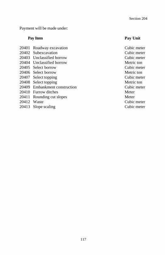
Section 204
117
Payment will be made under:
Pay Item Pay Unit
20401 Roadway excavation Cubic meter20402 Subexcavation Cubic meter20403 Unclassified borrow Cubic meter20404 Unclassified borrow Metric ton20405 Select borrow Cubic meter20406 Select borrow Metric ton20407 Select topping Cubic meter20408 Select topping Metric ton20409 Embankment construction Cubic meter20410 Furrow ditches Meter20411 Rounding cut slopes Meter20412 Waste Cubic meter20413 Slope scaling Cubic meter
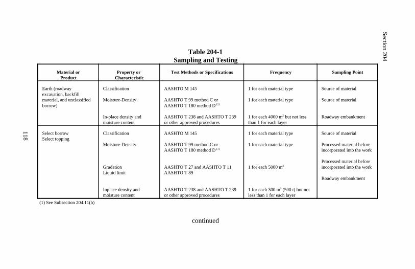
Section 204
118
Table 204-1Sampling and Testing
Material orProduct
Property or Characteristic
Test Methods or Specifications Frequency Sampling Point
Earth (roadway excavation, backfill material, and unclassifiedborrow)
Classification
Moisture-Density
In-place density and moisture content
AASHTO M 145
AASHTO T 99 method C or AASHTO T 180 method D (1)
AASHTO T 238 and AASHTO T 239or other approved procedures
1 for each material type
1 for each material type
1 for each 4000 m but not less2
than 1 for each layer
Source of material
Source of material
Roadway embankment
Select borrowSelect topping
Classification
Moisture-Density
GradationLiquid limit
Inplace density and moisture content
AASHTO M 145
AASHTO T 99 method C or AASHTO T 180 method D (1)
AASHTO T 27 and AASHTO T 11AASHTO T 89
AASHTO T 238 and AASHTO T 239or other approved procedures
1 for each material type
1 for each material type
1 for each 5000 m3
1 for each 300 m (500 t) but not3
less than 1 for each layer
Source of material
Processed material beforeincorporated into the work
Processed material beforeincorporated into the work
Roadway embankment
(1) See Subsection 204.11(b)
continued
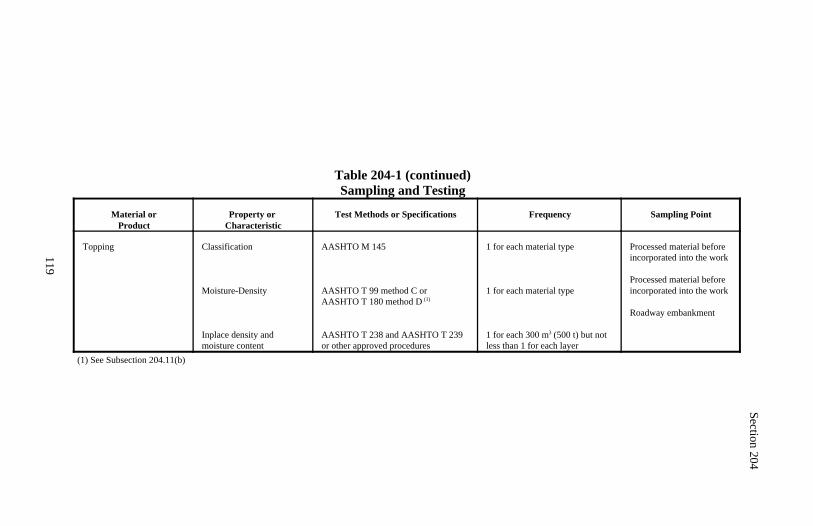
Section 204
119
Table 204-1 (continued)Sampling and Testing
Material orProduct
Property or Characteristic
Test Methods or Specifications Frequency Sampling Point
Topping Classification
Moisture-Density
Inplace density and moisture content
AASHTO M 145
AASHTO T 99 method C or AASHTO T 180 method D (1)
AASHTO T 238 and AASHTO T 239or other approved procedures
1 for each material type
1 for each material type
1 for each 300 m (500 t) but not3
less than 1 for each layer
Processed material beforeincorporated into the work
Processed material beforeincorporated into the work
Roadway embankment
(1) See Subsection 204.11(b)
120
Section 205.) ROCK BLASTING
Description
205.01 This work consists of fracturing rock and constructing stable final rockcut faces using controlled blasting and production blasting techniques. Controlled blasting uses explosives to form a shear plane in the rock along aspecified backslope. Controlled blasting includes presplitting and cushionblasting.
Production blasting uses explosives to fracture rock.
Material
205.02 Conform to the following Subsection:
Explosives and blasting accessories 725.25
Construction Requirements
205.03 Regulations. Furnish copies or other proof of all applicable permitsand licenses. Comply with Federal, state, and local regulations on thepurchase, transportation, storage, and use of explosive material. Federalregulations include the following:
(a) Safety and health. OSHA, 29 CFR Part 1926, Subpart U.
(b) Storage, security, and accountability. Bureau of Alcohol, Tobacco,and Firearms (BATF), 27 CFR Part 181.
(c) Shipment. DOT, 49 CFR Parts 171-179, 390-397.
205.04 Blasting Plan. Submit a blasting plan at least 14 days before drillingoperations begin or whenever a change in drilling and blasting procedures isproposed. Include full details of drilling and blasting patterns and thetechniques proposed for controlled and production blasting includingprovisions for loading wet holes.
As a minimum, the blasting plan shall contain the following:
(a) Maximum dimensions for width, length, and depth of shot.
Section 205
121
(b) Typical plan and section view of the drill pattern for controlled blastholes and production blast holes. Show the free face, burden, hole diameters,depths, spacings, inclinations, and depth of subdrilling if any.
(c) Loading pattern diagram showing:
(1) Location of each hole(2) Location and amount of each type of explosive in each hole includ-ing primer and initiators(3) Location, type, and depth of stemming
(d) Initiation and delay methods, delay times, and overall powder factor.
(e) Manufacturer's data sheets for all explosives, primers, initiators, and otherblasting devices.
(f) Working procedures and safety precautions for storing, transporting, andhandling explosives.
(g) Working procedures and safety precautions for blasting.
The blasting plan is for quality control and record keeping purposes. Thereview of the blasting plan does not relieve the Contractor of the responsibilityfor using existing drilling and blasting technology and for obtaining therequired results.
205.05 Blaster-In-Charge. At least 10 days before delivery or use of expl-osive material, designate in writing a blaster-in-charge. Submit evidence thatthe blaster-in-charge has a valid state blaster's license or other license issuedby an equivalent licensing body for the type of blasting required.
205.06 Test Blasting. Drill, blast, and excavate one or more short testsections as proposed in the blasting plan before full-scale drilling and blasting.Test blasts may be made away from or at the final slope line.
Space blast holes for controlled blasting 750 millimeters apart for the initialtest blast. Adjust the spacing as approved. Use the approved spacing in thefull-scale blasting or subsequent test blasts if necessary.
Section 205
122
When a test blast is determined to be unacceptable, revise the blasting plan andmake an additional test blast. A test blast is unacceptable when it results infragmentation beyond the final rock face, fly rock, vibration, air blast, over-break, damage to the final rock face, or is a violation of other requirements.
205.07 Controlled Blasting.
(a) General. Drill and blast according to the blasting plan. Use controlledblasting methods to form the final rock cut faces when the rock height ismore than 3 meters above ditch grade and slopes are staked 2:1 or steeper.
Use downhole angle or fan drill blast holes for pioneering the tops of rockcuts or preparing a working platform for controlled blasting. Use the blasthole diameter established for controlled blasting and a hole spacing notexceeding 750 millimeters.
(b) Drilling. Remove overburden soil and loose rock along the top of theexcavation for at least 10 meters beyond the production hole drilling limitsor to the end of the cut.
Drill 75±25-millimeter diameter controlled blast holes along the final rockface line. Drill controlled blast holes within 75 millimeters of the proposedsurface location. Drill controlled blast holes at least 10 meters beyond theproduction holes to be detonated or to the end of the cut.
Use drilling equipment with mechanical or electrical-mechanical devices thataccurately control the angle the drill enters the rock. Select a lift height andconduct drilling operations so the blast hole spacing and down-hole align-ment does not vary more than 225 millimeters from the proposed spacing andalignment. When more than 5 percent of the holes exceed the variance,reduce the lift height and modify the drilling operations until the blast holesare within the allowable variance. Maximum lift height is limited to 15meters.
A 300-millimeter offset is allowed for a working bench at the bottom of eachlift for drilling the next lower controlled blasting hole pattern.
Adjust the drill inclination angle or the initial drill collar location so therequired ditch cross-section is obtained when the bench is used.
Section 205
123
Drilling 0.5 meter below the ditch bottom is allowed for removing the toe.
(c) Blasting. Free blast holes of obstructions for their entire depth. Placecharges without caving the blast hole walls.
Use the types of explosives and blasting accessories necessary to obtain therequired results. A bottom charge may be larger than the line charges if nooverbreak results. Do not use bulk ammonium nitrate and fuel oil forcontrolled blasting.
Stem the upper portion of all blast holes with dry sand or other granularmaterial passing a 9.5 millimeter sieve.
Where presplitting, delay the nearest production blast row at least 25 milli-seconds after blasting the presplit line. Presplit a minimum of 10 metersahead of production blasting zone.
Where cushion (trim) blasting, delay the cushion blast row from 25 to 75milliseconds after blasting the nearest production row.
205.08 Production Blasting.
(a) General. Drill production holes and blast according to the blasting plan.Take all necessary precautions to minimize blast damage to the final rockface.
Following a blast, stop work in the entire blast area and check for misfiresbefore allowing workers to return to excavate the rock.
Remove or stabilize all cut face rock that is loose, hanging, or potentiallydangerous. Scale by hand methods using a standard steel mine scaling rod.Machine scale using hydraulic splitters or light blasting when necessary.Leave minor irregularities or surface variations in place if they do not createa hazard. Drill the next lift only after the cleanup work and stabilizationwork is complete.
If blasting operations cause fracturing of the final rock face, repair orstabilize it in an approved manner. Repair or stabilization may includeremoval, rock bolting, rock dowels, or other stabilization techniques.
Section 205
124
Halt blasting operations if any of the following occur:
(1) Slopes are unstable.(2) Slopes exceed tolerances.(3) Backslope damage occurs.(4) Safety of the public is jeopardized.(5) Property or natural features are endangered.(6) Fly rock is generated.
(b) Drilling. Drill the row of production blast holes closest to the controlledblast line parallel and no closer than 2 meters to the controlled blast line. Donot drill production blast holes lower than the bottom of the controlled blastholes.
(c) Blasting. Use the types of explosives and blasting accessories that willobtain the desired fragmentation. Clean the blast holes, place the charges,and stem the holes according to Subsection 205.07(c). Detonate productionholes on a delay sequence toward a free face.
205.09 Blasting Log. Submit a blasting log for each blast. The blasting logshall include the following:
(a) All actual dimensions of the shot including blast hole depths, burden,spacing, subdrilling, stemming, powder loads, and timing.
(b) A drawing or sketch showing the direction of the face, or faces, and thephysical shot layout.
205.10 Acceptance. Material for rock blasting will be evaluated under Sub-sections 106.02 and 106.03.
Rock blasting work and services will be evaluated under Subsections 106.02and 106.04.
Measurement
205.11 Measure controlled blast hole by the meter based on the actual lengthof drilling as recorded in the blasting log.
Do not measure production blasting for payment.
Section 205
125
Payment
205.12 The accepted quantities, measured as provided above, will be paid atthe contract price per unit of measurement for the pay item listed below that isshown in the bid schedule. Payment will be full compensation for the workprescribed in this Section. See Subsection 109.05.
Payment will be made under:
Pay Item Pay Unit
20501 Controlled blast hole Meter
Section 206 Reserved
126
Section 207. ) EARTHWORK GEOTEXTILES
Description
207.01 This work consists of furnishing and placing a geotextile as a per-meable separator or permanent erosion control measure.
Geotextile types are designated as shown in Subsection 714.01.
Material
207.02 Conform to the following Subsection:
Geotextile 714.01
Construction Requirements
207.03 General. Where placing a geotextile on native ground, cut the treesand shrubs flush with the ground surface. Do not remove the topsoil andvegetation mat. Remove all sharp objects and large rocks. Fill depressions orholes with suitable material to provide a firm foundation.
Replace or repair all geotextile that is torn, punctured, or muddy. Remove thedamaged area and place a patch of the same type of geotextile overlapping 1meter beyond the damaged area.
207.04 Separation and Stabilization Applications. Where placing a geo-textile on a subgrade, prepare according to Subsections 204.13(c) and (d).
Place the geotextile smooth and free of tension, stress, or wrinkles. Fold or cutthe geotextile to conform to curves. Overlap in the direction of construction.Overlap the geotextile a minimum of 0.5 meter at the ends and sides ofadjoining sheets or sew the geotextile joints according to the manufacturer'srecommendations. Do not place longitudinal overlaps below anticipated wheelloads. Hold the geotextile in place with pins, staples, or piles of cover materi-al.
End dump the cover material onto the geotextile from the edge of the geo-textile or from previously placed cover material. Do not operate equipmentdirectly on the geotextile. Spread the end-dumped pile of cover materialmaintaining a minimum lift thickness of 300 millimeters. Compact the covermaterial with rubber-tired or nonvibratory smooth drum rollers.
Section 207
127
Avoid sudden stops, starts, or turns of the construction equipment. Fill all rutsfrom construction equipment with additional cover material. Do not regraderuts with placement equipment.
Place subsequent lifts of cover material in the same manner. Vibratorycompactors may be used for compacting subsequent lifts. If foundation failuresoccur, repair the damaged areas and revert to the use of nonvibratorycompaction equipment.
207.05 Permanent Erosion Control Applications. Place and anchor thegeotextile on an approved smooth-graded surface. For slope or wave protec-tion, place the long dimension of the geotextile down the slope. For streambank protection, place the long dimension of the geotextile parallel to thecenterline of the channel.
Overlap the geotextile a minimum of 300 millimeters at the ends and sides ofadjoining sheets or sew the geotextile joints according to the manufacturer'srecommendations. Overlap the uphill or upstream sheet over the downhill ordownstream sheet. Offset end joints of adjacent sheets a minimum of 1.5meters. Pins may be used to hold the geotextile sheets in place. Space pinsalong the overlaps at approximately 1-meter centers.
Place aggregate, slope protection, or riprap on the geotextile starting at the toeof the slope and proceed upward. Place riprap onto the geotextile from aheight of less than 300 millimeters. Place slope protection rock or aggregatebackfill onto the geotextile from a height less than 1 meter. In underwaterapplications, place the geotextile and cover material in the same day.
207.06 Acceptance. Material for earthwork geotextile will be evaluated underSubsections 106.02, 106.03, and 714.01.
Earthwork geotextile installation will be evaluated under Subsections 106.02and 106.04.
Measurement
207.07 Measure earthwork geotextile by the square meter excluding over-laps.

Section 207
128
Payment
207.08 The accepted quantities, measured as provided above, will be paid atthe contract price per unit of measurement for the pay item listed below that isshown in the bid schedule. Payment will be full compensation for the workprescribed in this Section. See Subsection 109.05.
Payment will be made under:
Pay Item Pay Unit
20701 Earthwork geotextile type ____ Square meter
129
Section 208.) STRUCTURE EXCAVATION ANDBACKFILL FOR SELECTED MAJOR STRUCTURES
Description
208.01 This work consists of excavating material for the construction ofselected structures. The work includes preserving channels, shoring andbracing, constructing cofferdams, sealing foundations, dewatering, excavating,preparing foundations, backfilling, and subsequent removal of safety featuresand cofferdams.
Material
208.02 Conform to the following Sections and Subsections:
Concrete 552Foundation fill 704.01Seal concrete 552Structural backfill 704.04
Construction Requirements
208.03 Preparation for Structure Excavation. Clear the area of vegetationand obstructions according to Sections 201 and 203.
208.04 General. Excavate trenches or foundation pits to a width and lengththat allows room for work. When excavation is complete, request approval asto the character and suitability of the foundation material. The foundation shallprovide a firm foundation of uniform density throughout its length and width.
Where necessary to blast rock, blast according to Section 205.
Follow OSHA safety regulations (29 CFR, Part 1926, Subpart P, Excavation)for sloping the sides of excavations, using shoring and bracing, and for usingother safety features. When sides of excavations are sloped for safetyconsiderations, provide one copy of the design that demonstrates conformitywith OSHA regulations. Submit working drawings and construction detailsaccording to Subsection 104.03 where support systems, shield systems, or otherprotective systems are used. Drawings shall demonstrate conformity withregulations.
Section 208
130
Remove safety features when no longer necessary. Remove shoring andbracing to at least 0.5 meter below the surface of the finished ground.
Saw cut existing pavements or concrete structures adjacent to the area to beexcavated that are designated to remain.
Conserve suitable material for structural backfill from excavated material. Donot deposit excavated material in or near a waterway. Do not stockpileexcavated material or allow equipment closer than 0.6 meter from the edge ofthe excavation.
Dispose of unsuitable or excess material according to Subsection 204.14. Ifapproved, suitable material may be used in embankment construction.
Remove all water as necessary to perform work.
208.05 Channel Preservation. Perform work in or next to a running water-way as follows:
(a) Excavate inside cofferdams, sheeting, or other separations such as dikesor sandbags.(b) Do not disturb the natural bed of the waterway adjacent to the work.(c) Backfill the excavation with structural backfill to original groundline.
208.06 Cofferdams. Use cofferdams when excavating under water or whenthe excavation is affected by groundwater.
Submit working drawings showing proposed methods and construction detailsof cofferdams according to Subsection 104.03. Shore and constructcofferdams according to OSHA standards. Cofferdams shall:
(a) Extend below the bottom of the footing.(b) Be braced to withstand pressure without buckling and secured in placeto prevent tipping or movement.(c) Be as watertight as practicable.(d) Provide sufficient clearance for the placement of forms and the inspec-tion of their exteriors.(e) Provide for dewatering.(f) Protect fresh concrete against damage from sudden rises in waterelevation.(g) Prevent damage to the foundation by erosion.
Section 208
131
When no longer required, remove all cofferdam material down to the naturalbed of the waterway. Remove cofferdam material outside the waterway to aminimum of 0.5 meter below the surface of the finished ground.
208.07 Foundation Seal. Where a foundation area cannot be pumpedreasonably free of water, provide a foundation seal of seal concrete. Designseal concrete according to Subsection 552.03.
Furnish and place seal concrete according to Section 552. While placing afoundation seal, maintain the water level inside the cofferdam at the same levelas the water outside the cofferdam. Where a foundation seal is placed in tidalwater, vent or port the cofferdam at low water level.
Do not dewater a concrete-sealed cofferdam until the concrete strength issufficient to withstand the hydrostatic pressure.
208.08 Dewatering. While placing concrete, locate and operate the pumpsoutside the foundation form. If pumping is permitted from the interior of anyfoundation enclosure, pump in a manner to avoid removal or disturbance ofconcrete material.
208.09 Foundation Preparation. Prepare footing foundations as follows:
(a) Footings placed on bedrock. Cut the bottom of the excavation to thespecified elevation, either level or stepped or serrated. Clean the foundationsurface of loose or disintegrated material. Clean and grout all seams andcrevices.
(b) Footings placed on an excavated surface other than bedrock. Do notdisturb the bottom of the foundation excavation. Remove material tofoundation grade and compact the foundation immediately before concreteis placed.
(c) Footings keyed into undisturbed material. Excavate the foundation tothe neat lines of the footing and compact the foundation. Where materialdoes not stand vertically, fill all space between the neat lines of the footingand the remaining undisturbed material with concrete. If the excavation isbelow the top of the footing, fill only to the top of the excavation. Concreteplaced against steel sheet piles in cofferdams is considered as being againstundisturbed material.
Section 208
132
(d) Unstable material below footing elevation. Excavate unstable materialbelow foundation grade and replace it with foundation fill. Place foundationfill material in horizontal layers that when compacted do not exceed 150millimeters in depth. Compact each layer according to Subsection 208.11.
(e) Foundations using piles. Excavate to the foundation elevation and drivethe piles. Remove all loose and displaced material and reshape the bottomof the excavation to the foundation elevation. Smooth and compact the bedto receive the footing.
208.10 Backfill. Backfill with structural backfill material.
Place backfill in horizontal layers that do not exceed 150 millimeters incompacted thickness. Compact each layer according to Subsection 208.11.
Bring structural backfill up evenly on all sides of the structure as appropriate.Extend each layer to the limits of the excavation or to natural ground.
Do not place structural backfill against concrete less than 7 days old or until 90percent of the design strength is achieved.
208.11 Compacting. Determine optimum moisture content and maximumdensity according to AASHTO T 99 method C. Adjust the moisture contentof the backfill material to a moisture content suitable for compaction.
Compact material placed in all layers to at least 95 percent of the maximumdensity. Determine the inplace density and moisture content according to A-ASHTO T 238 and AASHTO T 239 or other approved test procedures.
208.12 Acceptance. Material for structural backfill and foundation fill willbe evaluated under Subsections 106.02 and 106.04. See Table 208-1 forminimum sampling and testing requirements.
Structure excavation and backfill work will be evaluated under Subsections106.02 and 106.04. See Table 208-1 for minimum sampling and testingrequirements.
Section 208
133
Shoring, bracing, and cofferdams will be evaluated under Subsections106.02 and 106.04.
Clearing will be evaluated under Sections 201 and 203.
Seal concrete will be evaluated under Section 552.
Measurement
208.13 Measure structure excavation by the cubic meter in place in its originalposition. Do not include the following volumes:
(a) Material excavated outside vertical planes located 450 millimeters out-side and parallel to the neat lines of footings or foundations. Use thesevertical planes to determine pay quantities regardless of the amount ofmaterial excavated inside or outside these planes.
(b) Any material included within the staked limits of the roadway excavation,such as contiguous channel changes and ditches, for which payment is other-wise provided in the contract.
(c) Water or other liquid material.
(d) Material excavated before the survey of elevations and measurements ofthe original ground.
(e) Material rehandled, except when the contract specifically requires exca-vation after embankment placement.
Measure foundation fill by the cubic meter in place.
Measure structural backfill by the cubic meter in place. Limit the volume ofstructural backfill measured to that placed inside vertical planes located 450 -millimeters outside and parallel to the neat lines of footings or foundations.Use these vertical planes to determine pay quantities regardless of the amountof backfill material placed outside these planes.
Measure shoring and bracing, and cofferdams by the lump sum.
Measure seal concrete under Section 552.
Section 208
134
Payment
208.14 The accepted quantities, measured as provided above, will be paid atthe contract price per unit of measurement for the pay items listed below thatare shown in the bid schedule. Payment will be full compensation for the workprescribed in this Section. See Subsection 109.05.
Payment for structure excavation, shoring and bracing, and cofferdams will befull compensation for excavation to a depth of 2 meters below the lowestelevation shown on the plans for each foundation structure. When theexcavation exceeds 2 meters, either the Contractor or the CO may request anequitable price adjustment for the depth in excess of 2 meters.
Payment will be made under:
Pay Item Pay Unit
20801 Structure excavation Cubic meter20802 Foundation fill Cubic meter20803 Structural backfill Cubic meter20804 Shoring and bracing Lump sum20805 Cofferdams Lump sum
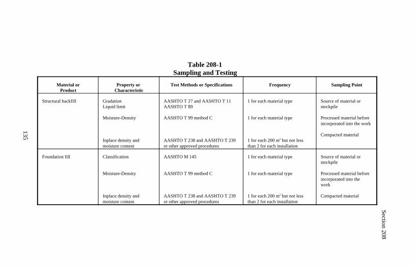
Section 208
135
Table 208-1Sampling and Testing
Material orProduct
Property or Characteristic
Test Methods or Specifications Frequency Sampling Point
Structural backfill GradationLiquid limit
Moisture-Density
Inplace density and moisture content
AASHTO T 27 and AASHTO T 11AASHTO T 89
AASHTO T 99 method C
AASHTO T 238 and AASHTO T 239or other approved procedures
1 for each material type
1 for each material type
1 for each 200 m but not less3
than 2 for each installation
Source of material orstockpile
Processed material beforeincorporated into the work
Compacted material
Foundation fill Classification
Moisture-Density
Inplace density and moisture content
AASHTO M 145
AASHTO T 99 method C
AASHTO T 238 and AASHTO T 239or other approved procedures
1 for each material type
1 for each material type
1 for each 200 m but not less3
than 2 for each installation
Source of material orstockpile
Processed material beforeincorporated into the work
Compacted material
136
Section 209.) STRUCTURE EXCAVATIONAND BACKFILL
Description
209.01 This work consists of excavating material for the construction of allstructures except those specifically designated under Section 208. The workincludes preserving channels, shoring and bracing, sealing foundations, de-watering, excavating, preparing foundations, bedding, and backfilling.
Material
209.02 Conform to the following Sections and Subsections:
Backfill material 704.03Bedding material 704.02Concrete 601Foundation fill 704.01Seal concrete 552Unclassified borrow 704.06
Construction Requirements
209.03 Preparation for Structure Excavation. Clear the area of vegetationand obstructions according to Sections 201 and 203.
209.04 General. Excavate trenches or foundation pits according to Subsec-tion 208.04. Excavate to foundation grade without unduly disturbing the trenchor foundation surface. Foundation grade is the elevation at the bottom of anybedding for installing the structure. Compact the foundation.
209.05 Channel Preservation. Preserve channels according to Subsection208.05, except excavate inside separations such as dikes or sandbags.
209.06 Foundation Seal. Where necessary for a foundation seal, constructa foundation seal according to Subsection 208.07.
Section 209
137
209.07 Dewatering. Where necessary to dewater, dewater according toSubsection 208.08.
209.08 Foundation Preparation. Excavate any unsuitable material presentat foundation grade, and replace it with foundation fill. Place and compact thefoundation fill material according to Subsection 208.09(d).
Where a footing is required to be keyed into undisturbed material, preparefoundation and construct footing according to Subsection 208.09(c).
209.09 Bedding. Place bedding material as follows:
(a) Structures other than culverts. Construct bedding when required bythe contract. Place and shape bedding material in layers that when com-pacted do not exceed 150 millimeters in depth. Compact each layer ac-cording to Subsection 209.11. When no bedding material class is specified,use class B bedding material.
(b) Culverts. Bed culverts on a prepared foundation. Use one of thefollowing classes. When no class is specified, use class C.
(1) Class A. Place a continuous cradle of class A bedding material.Place the culvert while the concrete is still plastic. Do not backfill untilthe concrete reaches initial set.
(2) Class B. Loosely place a 150-millimeter thick layer of class B bed-ding material. Place and shape additional bedding material to fit at least10 percent of the culvert height. Where applicable, recess the shapedbedding to receive the culvert joints. Place the culvert in the bedding.Extend the bedding material up the sides of the culvert to cover 30percent of the culvert height.
(3) Class C. Loosely place a layer of class C bedding material to a thick-ness equal to at least 10 percent of the culvert height. Place and shapeadditional bedding material to fit at least 10 percent of the culvert height.Where applicable, recess the shaped bedding to receive the culvert joints.Place the culvert in the bedding.
Section 209
138
209.10 Backfill. Backfill as follows:
(a) General. Place backfill in horizontal layers that when compacted do notexceed 150 millimeters in depth. Compact each layer according toSubsection 209.11.
Bring backfill up evenly on all sides of the structure, and extend each layerto the limits of the excavation or to natural ground.
Do not place backfill against concrete less than 7 days old or until 90 percentof the design strength is achieved.
(b) Culvert. Where installing plastic pipe, use backfill material conformingto AASHTO M 145 classification group A-1, A-2, or A-3.
Place and compact backfill material under exposed portions of the haunch.Extend each layer to the sides of the excavation, the natural groundline, or3 times the span of the pipe, whichever is less. Repeat the layering processto a minimum of 300 millimeters above the top of the pipe.
Complete the backfilling of the trench with suitable roadway excavation orunclassified borrow. Place the material in layers that when compacted do notexceed 150 millimeters in depth. Compact each layer according toSubsection 209.11.
For multiple installations, place and compact backfill material layers evenlyon each side of each culvert.
(c) Arch culverts with headwalls. Backfill according to one of the fol-lowing:
(1) Before headwalls are in place. Place and compact the first backfillmaterial midway between the ends of the arch. Place and compactbackfill material in layers on both sides of the arch to form as narrow aramp as possible. Build the ramp evenly on both sides until reaching thetop of the arch. Place the remainder of the backfill material from the topof the ramp working both ways to the ends. Compact the backfill materialevenly in layers on both sides of the arch.
Section 209
139
(2) After headwalls are in place. Place and compact the first backfillmaterial adjacent to one headwall. Place and compact backfill materialevenly in layers on both sides of the arch adjacent to the headwall untilreaching the top of the arch. Place remainder of the backfill material fromthe top of the arch working toward the other headwall. Compact thebackfill material evenly in layers on both sides of the arch.
(d) Patching existing pavement areas. Construct the top 375 millimeterswith 300 millimeters of crushed aggregate according to Section 301 and 75millimeters of asphalt concrete according to Section 402 or 417.
209.11 Compacting. Determine optimum moisture content and maximumdensity according to AASHTO T 99 method C. Adjust the moisture contentof the backfill material to a moisture content suitable for compaction.
Compact material placed in all layers to at least 95 percent of the maximumdensity. Determine the inplace density and moisture content according to A-ASHTO T 238 and AASHTO T 239 or other approved test procedures.
209.12 Acceptance. Material for backfill, bedding, and foundation fill willbe evaluated under Subsections 106.02 and 106.04, except concrete forbedding or backfill will be evaluated according to Section 601. See Table209-1 for minimum sampling and testing requirements.
Structural excavation and backfill work will be evaluated under Subsections106.02 and 106.04. See Table 209-1 for minimum sampling and testingrequirements.
Shoring, bracing, and cofferdams will be evaluated under Subsections106.02 and 106.04. Clearing will be evaluated under Sections 201 and 203.
Seal concrete will be evaluated under Section 552.

Section 209
140
Measurement and Payment
209.13 See Subsection 109.05.
Do not measure structure excavation and backfill for payment.
Measure concrete for class A bedding material under Section 601.
Measure foundation fill under Section 208.
Measure seal concrete under Section 552.
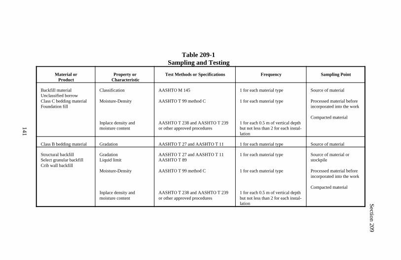
Section 209
141
Table 209-1Sampling and Testing
Material orProduct
Property or Characteristic
Test Methods or Specifications Frequency Sampling Point
Backfill material Unclassified borrowClass C bedding materialFoundation fill
Classification
Moisture-Density
Inplace density and moisture content
AASHTO M 145
AASHTO T 99 method C
AASHTO T 238 and AASHTO T 239or other approved procedures
1 for each material type
1 for each material type
1 for each 0.5 m of vertical depthbut not less than 2 for each instal-lation
Source of material
Processed material beforeincorporated into the work
Compacted material
Class B bedding material Gradation AASHTO T 27 and AASHTO T 11 1 for each material type Source of material
Structural backfillSelect granular backfillCrib wall backfill
GradationLiquid limit
Moisture-Density
Inplace density and moisture content
AASHTO T 27 and AASHTO T 11AASHTO T 89
AASHTO T 99 method C
AASHTO T 238 and AASHTO T 239or other approved procedures
1 for each material type
1 for each material type
1 for each 0.5 m of vertical depthbut not less than 2 for each instal-lation
Source of material orstockpile
Processed material beforeincorporated into the work
Compacted material
142
Section 210.) PERMEABLE BACKFILL
Description
210.01 This work consists of furnishing and placing permeable backfill againstthe backfilled faces of retaining walls, wing walls, and abutments.
Material
210.02 Conform to the following Subsections:
Geotextile type I 714.01Permeable backfill 703.04Structural backfill 704.04
Construction Requirements
210.03 General. Do not place permeable backfill against a mortar course lessthan 4 days old.
Cover the inlet end of each weep hole and drain with a geotextile extending atleast 0.5 meter beyond the weep hole or drain. Place permeable backfill again-st the surface to be backfilled. Place structural backfill according to Subsection208.10 using methods which prevent the structural backfill from mixing withthe permeable backfill.
210.04 Acceptance. Material for permeable backfill will be evaluated underSubsections 106.02 and 106.04. See Table 210-1 for minimum sampling andtesting requirements.
Placement of permeable backfill will evaluated under Subsections 106.02 and106.04.
Geotextile will be evaluated under Section 207.
Structural backfill will be evaluated under Section 208.
Measurement
210.05 Measure permeable backfill by the cubic meter in the structure.

Section 210
143
Payment
210.06 The accepted quantities, measured as provided above, will be paid atthe contract price per unit of measurement for the pay items listed below thatare shown in the bid schedule. Payment will be full compensation for the workprescribed in this Section. See Subsection 109.05.
Payment will be made under:
Pay Item Pay Unit
21001 Permeable backfill Cubic meter
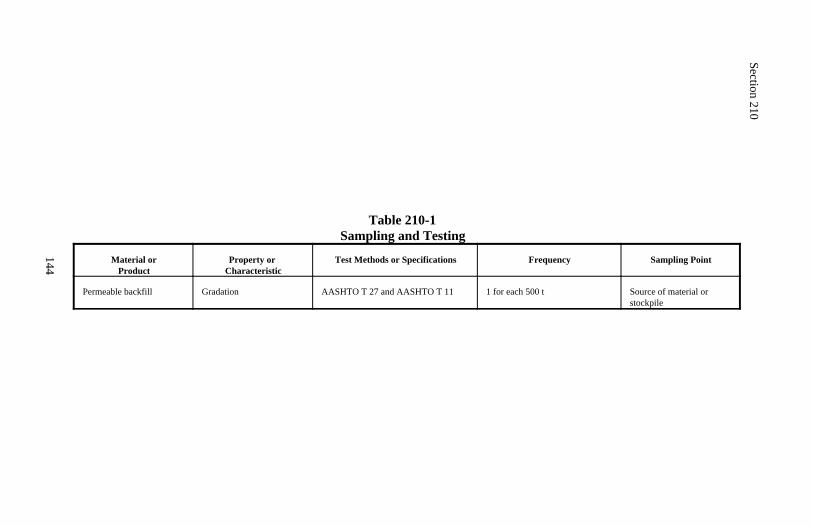
Section 210
144
Table 210-1Sampling and Testing
Material orProduct
Property or Characteristic
Test Methods or Specifications Frequency Sampling Point
Permeable backfill Gradation AASHTO T 27 and AASHTO T 11 1 for each 500 t Source of material orstockpile
145
Section 211.) ROADWAY OBLITERATION
Description
211.01 This work consists of obliterating and recontouring roadways, turnouts,parking areas, and other widened areas.
Construction Requirements
211.02 General. Scarify and bury or remove the existing pavement structure.Break down and bury or remove old structures. Fill ditches and restore theobliterated roadway to the approximate original ground contour or shape toblend with the terrain.
211.03 Rigid Material.
(a) Nonasphalt material. Break concrete pavements, curbs, gutters, side-walks, and other nonasphalt rigid material into pieces with maximumdimension of 300 millimeters. Bury under a minimum of 0.5 meters of soil.As an alternative to breaking and burying, remove the rigid material from theproject and dispose of it according to Subsection 203.05(a).
(b) Asphalt material. Dispose of asphalt material in a manner consistentwith state and local regulations. Asphalt material may be consideredhazardous waste. Furnish copies of the disposal permits. Where no regula-tions exist, dispose of the material as described in (a) above.
211.04 Nonrigid Material.
(a) Nonasphalt material. Scarify or rip the gravel, crushed stone, or othernonrigid surface, base, and subbase material. Mix the scarified or rippedmaterial with the underlying soil. Bury the mixture under at least 300millimeters of soil.
(b) Asphalt contaminated material. Dispose of asphalt contaminated mate-rial according to Subsection 211.03(b).
211.05 Shaping. Shape to blend with the existing terrain.
211.06 Acceptance. Roadway obliteration will be evaluated under Sub-sect-ion 106.02.
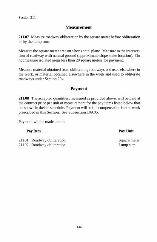
Section 211
146
Measurement
211.07 Measure roadway obliteration by the square meter before obliterationor by the lump sum.
Measure the square meter area on a horizontal plane. Measure to the intersec-tion of roadway with natural ground (approximate slope stake location). Donot measure isolated areas less than 20 square meters for payment.
Measure material obtained from obliterating roadways and used elsewhere inthe work, or material obtained elsewhere in the work and used to obliterateroadways under Section 204.
Payment
211.08 The accepted quantities, measured as provided above, will be paid atthe contract price per unit of measurement for the pay items listed below thatare shown in the bid schedule. Payment will be full compensation for the workprescribed in this Section. See Subsection 109.05.
Payment will be made under:
Pay Item Pay Unit
21101 Roadway obliteration Square meter21102 Roadway obliteration Lump sum
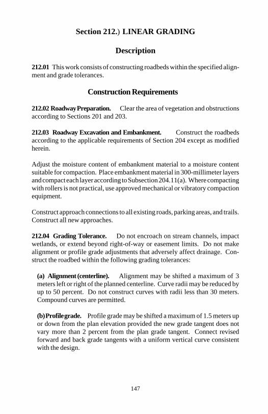
147
Section 212.) LINEAR GRADING
Description
212.01 This work consists of constructing roadbeds within the specified align-ment and grade tolerances.
Construction Requirements
212.02 Roadway Preparation. Clear the area of vegetation and obstructionsaccording to Sections 201 and 203.
212.03 Roadway Excavation and Embankment. Construct the roadbedsaccording to the applicable requirements of Section 204 except as modifiedherein.
Adjust the moisture content of embankment material to a moisture contentsuitable for compaction. Place embankment material in 300-millimeter layersand compact each layer according to Subsection 204.11(a). Where compactingwith rollers is not practical, use approved mechanical or vibratory compactionequipment.
Construct approach connections to all existing roads, parking areas, and trails.Construct all new approaches.
212.04 Grading Tolerance. Do not encroach on stream channels, impactwetlands, or extend beyond right-of-way or easement limits. Do not makealignment or profile grade adjustments that adversely affect drainage. Con-struct the roadbed within the following grading tolerances:
(a) Alignment (centerline). Alignment may be shifted a maximum of 3meters left or right of the planned centerline. Curve radii may be reduced byup to 50 percent. Do not construct curves with radii less than 30 meters.Compound curves are permitted.
(b) Profile grade. Profile grade may be shifted a maximum of 1.5 meters upor down from the plan elevation provided the new grade tangent does notvary more than 2 percent from the plan grade tangent. Connect revisedforward and back grade tangents with a uniform vertical curve consistentwith the design.
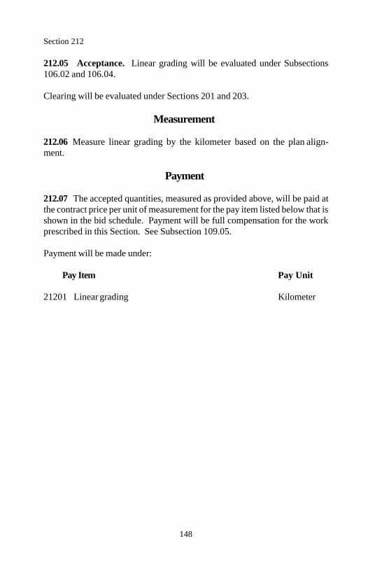
Section 212
148
212.05 Acceptance. Linear grading will be evaluated under Subsections106.02 and 106.04.
Clearing will be evaluated under Sections 201 and 203.
Measurement
212.06 Measure linear grading by the kilometer based on the plan align-ment.
Payment
212.07 The accepted quantities, measured as provided above, will be paid atthe contract price per unit of measurement for the pay item listed below that isshown in the bid schedule. Payment will be full compensation for the workprescribed in this Section. See Subsection 109.05.
Payment will be made under:
Pay Item Pay Unit
21201 Linear grading Kilometer
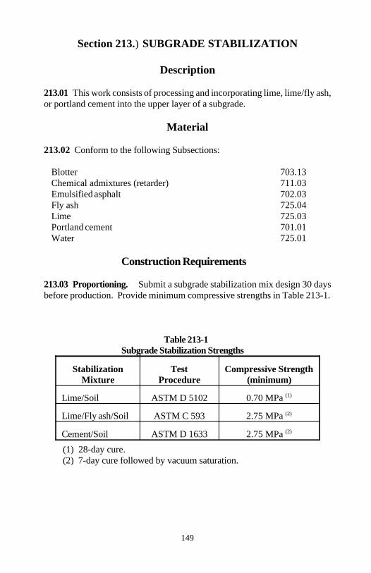
149
Section 213.) SUBGRADE STABILIZATION
Description
213.01 This work consists of processing and incorporating lime, lime/fly ash,or portland cement into the upper layer of a subgrade.
Material
213.02 Conform to the following Subsections:
Blotter 703.13Chemical admixtures (retarder) 711.03Emulsified asphalt 702.03Fly ash 725.04Lime 725.03Portland cement 701.01Water 725.01
Construction Requirements
213.03 Proportioning. Submit a subgrade stabilization mix design 30 daysbefore production. Provide minimum compressive strengths in Table 213-1.
Table 213-1Subgrade Stabilization Strengths
Stabilization Test Compressive StrengthMixture Procedure (minimum)
Lime/Soil ASTM D 5102 0.70 MPa (1)
Lime/Fly ash/Soil ASTM C 593 2.75 MPa (2)
Cement/Soil ASTM D 1633 2.75 MPa (2)
(1) 28-day cure.(2) 7-day cure followed by vacuum saturation.
Section 213
150
Include the following with the mix design, as applicable:
(a) Source of each component material(b) Results of the applicable tests(c) 90-kilogram sample of the subgrade soil(d) 25-kilogram sample of the fly ash(e) 10-kilogram sample of the lime(f) 10-kilogram sample of the cement(g) 2-kilogram sample of the retarder or other admixtures proposed
Begin production only after the mix design is approved. Furnish a new mixdesign if there is a change in a material source.
213.04 General. Store chemical additives and admixtures in closed,weatherproof containers. Prepare the subgrade according to Section 303.Scarify and pulverize the subgrade to a depth of 150 millimeters. Size andshape the subgrade material to a windrow or blanket that is suitable for mixing.Determine the optimum moisture content and maximum density according toAASHTO T 99 method C.
213.05 Application. Apply additives when the subgrade material is at least 3percent below optimum moisture content and at least 4 C. Do not apply whenexcessive additive is lost to washing or blowing or when the air temperature isexpected to fall below 4 C within 48 hours.
Apply additives at the required rates by one of the following methods:
(a) Dry method. Uniformly apply the additives by an approved spreader.A motor grader is not an approved spreader. Apply water using approvedmethods to obtain the proper moisture content for mixing and compaction.
(b) Slurry method. Mix additives with water and apply as a thin watersuspension or slurry using either trucks with approved distributors or rotarymixers. Equip the distributor truck or rotary mixer tank with an agitator tokeep the additives suspended in water. Make successive passes over thematerial to obtain the moisture and additive content for mixing andcompacting.
213.06 Mixing. Keep all traffic, except mixing equipment, off the spreadmaterial. Mix the material to obtain a homogeneous friable mixture.
Section 213
151
(a) Lime and lime/fly ash mixtures. Add water and thoroughly mix toadjust the moisture content of the mixture to the optimum moisture contentplus necessary hydration moisture. Hydration moisture is 1½ percent foreach percent of additive in the mixture. Complete the mixing within 6 hoursof additive application. Cure the mixture for 2 to 4 days by keeping it moist.
After curing, remix the mixture until 95 percent of all the mixture, exceptrock, passes a 45 millimeter sieve and at least 50 percent of the mixturepasses a 4.75 millimeter sieve when tested according to AASHTO T 27, ina nondried condition. Retarders may be added.
(b) Cement mixtures. Add water and thoroughly mix to adjust the moisturecontent of the mixture to 2 percent above the optimum moisture content.Complete the mixing within 2 hours of cement application.
Adjust the moisture content of the mixture to within 2 percent of the optimummoisture content.
213.07 Compacting and Finishing. Immediately after mixing, spread andcompact the mixture to at least 95 percent of the maximum density. Determinethe inplace density and moisture content according to AASHTO T 238 andAASHTO T 239 or other approved test procedures. If the time betweencompacting adjacent partial widths exceeds 30 minutes, or when tying into theprevious work, provide a construction joint according to Subsection 302.07.Finish the subgrade so it is smooth and suitable for placing a subsequentcourse.
213.08 Curing. Do not allow traffic on the stabilized subgrade. Keep thesubgrade continuously moist until the next course is placed. Apply water underpressure through a spray bar equipped with nozzles producing a fine, uniformspray. Place the next course within 7 days after compacting and finishing thesubgrade.
Placement of the next course may be deferred up to 21 days by sealing thesurface with rapid setting emulsified asphalt. Keep the surface continuouslymoist for at least 7 days after compacting and finishing. After the 7 days, applyundiluted CRS-2 or RS-2 emulsified asphalt at a rate of 1.1 liters per squaremeter according to Section 409. Provide a continuous film over the surface.If the surface is opened to public traffic, furnish and apply blotter according toSection 411.
Section 213
152
If the subgrade looses stability, density, or finish before placement of the nextcourse, reprocess or recompact the subgrade as necessary to restore thestrength of the damaged material to that specified in the mix design. Reapplythe emulsified asphalt seal where the continuous film is damaged.
213.09 Acceptance. Material for blotter, chemical admixtures (retarder), flyash, lime, portland cement, and water will be evaluated under Subsections106.02 and 106.03. Emulsified asphalt will be evaluated under Subsections106.03 and 702.09. Subgrade stabilization work will be evaluated under Subsections 106.02 and106.04. See Table 213-2 for minimum sampling and testing requirements.
Reconditioning of subgrade will be evaluated under Section 303.
Emulsified asphalt seal will be evaluated under Section 409.
Measurement
213.10 Measure subgrade stabilization by the square meter. Measure thewidth horizontally to include the top of subgrade width and allowable curvewidening. Measure length horizontally along the centerline of the roadway.
Measure lime, cement, and fly ash by the metric ton.
Measure emulsified asphalt under Section 409.
Measure blotter under Section 411.
Payment
213.11 The accepted quantities, measured as provided above, will be paid atthe contract price per unit of measurement for the pay items listed below thatare shown in the bid schedule. Payment will be full compensation for the workprescribed in this Section. See Subsection 109.05.

Section 213
153
Payment will be made under:
Pay Item Pay Unit
21301 Subgrade stabilization with ____________, Square meter__ millimeter depth
21302 Lime Metric ton21303 Cement Metric ton21304 Fly ash Metric ton
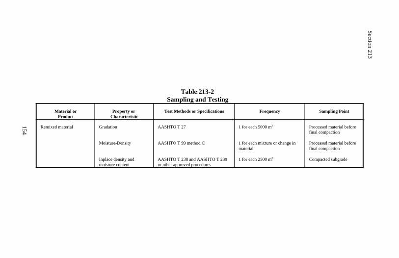
Section 213
154
Table 213-2Sampling and Testing
Material orProduct
Property or Characteristic
Test Methods or Specifications Frequency Sampling Point
Remixed material Gradation
Moisture-Density
Inplace density and moisture content
AASHTO T 27
AASHTO T 99 method C
AASHTO T 238 and AASHTO T 239or other approved procedures
1 for each 5000 m2
1 for each mixture or change inmaterial
1 for each 2500 m2
Processed material beforefinal compaction
Processed material beforefinal compaction
Compacted subgrade
155
DIVISION 250Structural Embankments
156
Section 251.) RIPRAP
Description
251.01 This work consists of furnishing and placing riprap for bank protec-tion, slope protection, drainage structures, and erosion control.
Riprap classes are designated as shown in Table 705-1.
Material
251.02 Conform to the following Subsections:
Geotextile type IV 714.01Mortar 712.05Riprap rock 705.02
Construction Requirements
251.03 General. Perform the work under Section 209. Dress the slope toproduce a smooth surface. Place geotextile required by the contract accordingto Section 207.
251.04 Placed Riprap. Placed riprap is rock placed on a prepared surface toform a well-graded mass.
Place riprap to its full thickness in one operation to avoid displacing theunderlying material. Do not place riprap material by methods that causesegregation or damage to the prepared surface. Place or rearrange individualrocks by mechanical or hand methods to obtain a dense uniform blanket witha reasonably smooth surface.
251.05 Keyed Riprap. Keyed riprap is rock placed on a prepared surface andkeyed into place by striking with a flat-faced weight.
Place rock for keyed riprap according to Subsection 251.04. Key the riprapinto place by striking the surface with a 1.2 meter by 1.5 meter flat-facedweight with a mass of approximately 2000 kilograms. Do not strike riprapbelow the water surface.
Section 251
157
251.06 Mortared Riprap. Mortared riprap is rock placed on a preparedsurface and with the voids filled with portland cement mortar.
Place rock for mortared riprap according to Section 251.04. Thoroughlymoisten the rocks and wash excess fines to the underside of the riprap. Placemortar only when the temperature is above 2 C and rising. Place the mortarin a manner to prevent segregation. Fill all voids without unseating the rocks.Provide weep holes through the riprap as required. Protect the mortared riprapfrom freezing and keep it moist for 3 days after the work is completed.
251.07 Acceptance. Rock for riprap will be evaluated under Subsection106.02.
Rock placement for riprap will be evaluated under Subsections 106.02 and106.04.
Structure excavation and backfill will be evaluated under Section 209.
Geotextile will be evaluated under Section 207.
Material for mortar will be evaluated under Subsections 106.02 and 106.03.Mortar will be evaluated under Subsections 106.02 and 106.04. Mortarplacement will be evaluated under Subsection 106.02. See Table 251-1 forminimum sampling and testing requirements.
Measurement
251.08 Measure riprap by the metric ton or by the cubic meter in place.
Payment
251.09 The accepted quantities, measured as provided above, will be paid atthe contract price per unit of measurement for the pay items listed below thatare shown in the bid schedule. Payment will be full compensation for the workprescribed in this Section. See Subsection 109.05.

Section 251
158
Payment will be made under:
Pay Item Pay Unit
25101 Placed riprap class ______ Cubic meter25102 Placed riprap class ______ Metric ton25103 Keyed riprap class ______ Cubic meter25104 Keyed riprap class ______ Metric ton25105 Mortared riprap class _____ Cubic meter
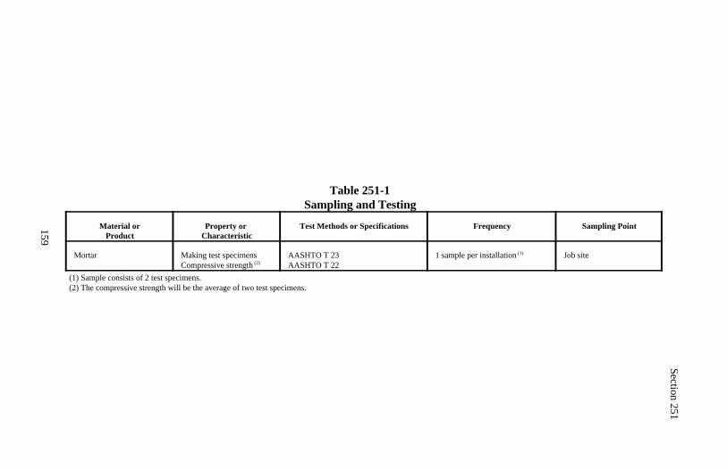
Section 251
159
Table 251-1Sampling and Testing
Material orProduct
Property or Characteristic
Test Methods or Specifications Frequency Sampling Point
Mortar Making test specimensCompressive strength (2)
AASHTO T 23AASHTO T 22
1 sample per installation (1) Job site
(1) Sample consists of 2 test specimens.(2) The compressive strength will be the average of two test specimens.
160
Section 252.) SPECIAL ROCK EMBANKMENT AND ROCK BUTTRESS
Description
252.01 Special rock embankment work consists of furnishing and placinghand-placed or mechanically-placed rock in fill sections. Rock buttress workconsists of furnishing and placing hand-placed or mechanically-placed rock incut sections.
Special rock embankments and rock buttresses are designated as hand-placedor mechanically-placed.
Material
252.02 Conform to the following Subsections:
Rock for buttresses 705.05Rock for special rock embankment 705.04
Construction Requirements
252.03 Placing Rock. Perform the work under Section 204 or 209 asrequired.
Place the rock in a stable orientation with minimal voids. Offset the rock toproduce a random pattern. Use spalls smaller than the minimum rock size tochock the larger rock solidly in position and to fill voids between the largerock.
Construct the exposed face of the rock mass reasonably uniform with noprojections beyond the neat line of the slope that are more than 300 millimetersfor mechanically-placed rock or 150 millimeters for hand-placed rock.
252.04 Acceptance. Rock for special rock embankment and rock buttress willbe evaluated under Subsection 106.02.
Rock placement for special rock embankment and rock buttress will beevaluated under Subsections 106.02 and 106.04.
Structure excavation and backfill will be evaluated under Section 209.

Section 252
161
Measurement
252.05 Measure special rock embankment and rock buttress by the cubicmeter in place or by the metric ton.
Payment
252.06 The accepted quantities, measured as provided above, will be paid atthe contract price per unit of measurement for the pay items listed below thatare shown in the bid schedule. Payment will be full compensation for the workprescribed in this Section. See Subsection 109.05.
Payment will be made under:
Pay Item Pay Unit
25201 Special rock embankment, Cubic meter25202 Special rock embankment, Metric ton25203 Rock buttress, Cubic meter25204 Rock buttress, Metric ton
162
Section 253.) GABIONS AND REVET MATTRESSES
Description
253.01 This work consists of constructing gabion structures and revetmattresses.
Material
253.02 Conform to the following Subsections:
Backfill material 704.03Gabion and revet mattress material 720.02Gabion and revet mattress rock 705.01Geotextile type IV 714.01Structural backfill 704.04
Construction Requirements
253.03 General. Survey according to Section 152 and verify the limits of thewall installation. Prepare and submit installation drawings according toSubsection 104.03. Perform the work under Section 209.
253.04 Basket Assembly. Do not damage wire coatings during basketassembly, structure erection, cell filling, or backfilling. Rotate the basketpanels into position and join the vertical edges with fasteners according toSubsection 253.05. Temporary fasteners may be used for basket assembly ifthey are supplemented during structure erection with permanent fastenersaccording to Subsection 253.05.
Rotate the diaphragms into position and join the vertical edges according toSubsection 253.05.
253.05 Structure Erection. Place the empty gabion baskets on thefoundation and interconnect the adjacent baskets along the top and verticaledges using permanent fasteners.
Where lacing wire is used, wrap the wire with alternating single and doubleloops every other mesh opening and not more than 150 millimeters apart.Where spiral binders are used, crimp the ends to secure the binders in place.Where alternate fasteners are used, space the fasteners in every mesh openingand not more than 150 millimeters apart.
Section 253
163
In the same manner, interconnect each vertical layer of baskets to the under-lying layer of baskets along the front, back, and sides. Stagger the verticaljoints between baskets of adjacent rows and layers by at least one cell length.
253.06 Cell Filling. Remove all kinks and folds in the wire mesh and properlyalign all the baskets. Place rock carefully in the basket cells to prevent bulgingof the baskets and to minimize voids in the rock fill. Maintain the basketalignment.
Place internal connecting wires in each unrestrained exterior basket cell greaterthan 0.3 meter in height. This includes interior basket cells left temporarilyunrestrained. Place internal connecting wires concurrently with rockplacement.
Fill the cells in any row or layer so that no cell is filled more than 0.3 meterabove an adjacent cell. Repeat this process until the basket is full and the lidbears on the final rock layer.
Secure the lid to the sides, ends, and diaphragms according to Sub-section 253.05. Make all exposed basket surfaces smooth and neat with nosharp rock edges projecting through the wire mesh.
253.07 Backfilling. Place a geotextile over the back face of the gabionstructure. Concurrently with the cell filling operation, backfill the area behindthe gabion structure with structural backfill according to Subsection 209.10.Compact each layer according to Subsection 209.11, except use an acceptablelightweight mechanical or vibratory compactor within one meter of the gabionstructure.
253.08 Revet Mattresses. Place a geotextile according to Section 207.Construct revet mattresses according to Subsections 253.04 through 253.06.Anchor the mattresses in place. Place geotextile against the vertical edges ofthe mattress and backfill against the geotextile using backfill material or otherapproved material. Overfill revet mattresses by 30 to 50 millimeters.
253.09 Acceptance. Material for gabion structures and revet mattresses willbe evaluated under Subsections 106.02 and 106.03.
Construction of gabion structures and revet mattresses will be evaluated underSubsections 106.02 and 106.04.
Section 253
164
Survey work will be evaluated under Section 152.
Geotextile will be evaluated under Subsection 207.
Structure excavation, structural backfill, and backfill material will be evaluatedunder Section 209. See Table 209-1 for minimum sampling and testing re-quirements.
Measurement
253.10 Measure gabions by the square meter of front wall face or by the cubicmeter in the structure.
Measure revet mattresses by the square meter.
Measure foundation fill under Section 208.
Payment
253.11 The accepted quantities, measured as provided above, will be paid atthe contract price per unit of measurement for the pay items listed below thatare shown in the bid schedule. Payment will be full compensation for the workprescribed in this Section. See Subsection 109.05.
Payment will be made under:
Pay Item Pay Unit
25301 Gabions, galvanized or aluminized coated Square meter25302 Gabions, polyvinyl chloride coated Square meter25303 Gabions, galvanized or aluminized coated Cubic meter25304 Gabions, polyvinyl chloride coated Cubic meter25305 Revet mattress, galvanized or aluminized coated Square meter25306 Revet mattress, polyvinyl chloride coated Square meter
165
Section 254.) CRIB WALLS
Description
254.01 This work consists of constructing concrete, metal, or timber cribretaining walls.
Material
254.02 Conform to the following Section and Subsections:
Bed course 704.09Concrete 601Crib wall backfill 704.12Hardware for timber structures 716.02Metal bin type crib walls 720.03Precast concrete units 725.11Reinforcing steel 709.01Structural backfill 704.04Treated structural timber and lumber 716.03
Construction Requirements
254.03 General. Survey according to Section 152 and verify the limits of thewall installation. Prepare and submit installation drawings according toSubsection 104.03. Perform the work under Section 209. When the wall is seton a rocky foundation, place 200 millimeters of bed course under the wall baseelements.
254.04 Erection. Furnish all necessary bolts, nuts, and hardware for completeassembly of the units into a continuous wall of connected units. Erect the cribwall according to the fabricator's or manufacturer's instructions. On curves,obtain the proper curvature for the face by using shorter stringers in the frontor rear panels. Construct the wall to within 25 millimeters in 3 meters from thelines and elevations shown on the plans.
(a) Concrete crib wall. Remove and replace all concrete members whichare cracked or damaged.
(b) Metal crib wall. Torque bolts for metal crib walls to at least 34 newtonmeters.
Section 254
166
(c) Timber crib wall. Construct timber cribs according to Section 557.
254.05 Backfilling. Backfill within the cribs with crib wall backfill accordingto Subsection 209.10. Backfill behind the cribs with structural backfillaccording to Subsection 209.10. Maintain an equal level of backfill within andbehind the cribs during the backfilling process. Compact each layer accordingto Subsection 209.11, except use an acceptable lightweight mechanical orvibratory compactor within one meter of the crib wall face.
254.06 Acceptance. Material for crib walls will be evaluated under Sub-sections 106.02 and 106.03. Furnish a production certification with eachshipment for the following:
(a) Metal bin type crib walls(b) Precast concrete units(c) Reinforcement steel(d) Treated structural timber and lumber
Construction of concrete, metal, or timber crib retaining wall construction willbe evaluated under Subsections 106.02 and 106.04.
Survey work will be evaluated under Section 152.
Structure excavation, crib wall backfill, structural backfill, and bed coursematerial will be evaluated under Section 209. See Table 209-1 for minimumsampling and testing requirements.
Concrete crib walls will be evaluated under Section 601.
Timber cribs walls will be evaluated under Section 557
Measurement
254.07 Measure crib walls by the square meter of front wall face.
Measure crib wall backfill placed within the cribs by the cubic meter.
Measure foundation fill under Section 208.
Section 254
167
Payment
254.08 The accepted quantities, measured as provided above, will be paid atthe contract price per unit of measurement for the pay items listed below thatare shown in the bid schedule. Payment will be full compensation for the workprescribed in this Section. See Subsection 109.05.
Payment will be made under:
Pay Item Pay Unit
25401 Reinforced concrete crib retaining wall Square meter25402 Metal crib retaining wall Square meter25403 Treated timber crib retaining wall Square meter25404 Crib wall backfill Cubic meter
168
Section 255.) MECHANICALLYSTABILIZED EARTH WALLS
Description
255.01 This work consists of constructing mechanically stabilized earth walls.
Material
255.02 Conform to the following Section and Subsections:
Concrete leveling pad 601Geotextile type IV 714.01Mechanically stabilized earth wall material 720.01Select granular backfill 704.10Structural backfill 704.04
Construction Requirements
255.03 General. Survey according to Section 152 and verify the limits of thewall installation. Prepare and submit installation drawings according to Sub-section 104.03. Perform the work under Section 209. Grade the foundationfor a width equal to the length of reinforcing mesh or strips plus 0.5 meter.Where the wall is set on a rocky foundation, place 150 millimeters of selectgranular backfill under the reinforcing mesh or strips.
For concrete-faced walls, provide a precast reinforced or a nonreinforced cast-in-place concrete leveling pad. Cure cast-in-place leveling pads a minimum of12 hours before placing wall panels.
255.04 Wall Erection. Erect the wall according to the drawings and themanufacturer's recommendations. When requested, have an experienced fieldrepresentative from the wall system manufacturer available during erection.
(a) Concrete-faced walls . Erect panels by means of lifting devices con-nected to the upper edge of the panel. Align precast facing panels within 19millimeters vertically and horizontally when measured with a 3-meterstraightedge.
Section 255
169
Make the joint openings 19±6 millimeters wide. Install joint materialaccording to the drawings. Cover all joints on the backside of the panelswith a 300-millimeter wide strip of geotextile. Overlap geotextile splices aminimum of 100 millimeters.
Hold the panels in position with temporary wedges or bracing during back-filling operations. Erect the wall so the overall vertical tolerance (top tobottom) does not exceed 13 millimeters per 3 meters of wall height.
(b) Wire-faced walls. Place backing mats and 6-millimeter hardware clothin successive horizontal lifts as backfill placement proceeds. Connect, tight-en, and anchor soil reinforcement elements to the wall facing units beforeplacing backfill. Do not exceed an individual lift vertical tolerance and anoverall wall (top to bottom) vertical tolerance of 25 millimeters per 3 metersof wall height. Place reinforcement elements within 25 millimeters verticallyabove the corresponding connection elevation at the wall face. Do not placereinforcing elements below the corresponding connection elevations. Do notdeviate from the designed batter of the wall by more than 25 millimeters per3 meters of wall height. Do not deviate more than 50 millimeters at anypoint in the wall from a 3-meter straightedge placed horizontally on thetheoretical plane of the design face.
(c) Gabion-faced walls. Place the first lift of backfill before filling thegabion baskets. Construct gabion structures according to Section 253. Layreinforcement mesh horizontally on compacted fill and normal to the face ofthe wall. Connect the gabion facing unit to reinforcement mesh with spiralbinders or tie wire at 100-millimeter nominal spacing with alternating singleand double locked loops. Pull and anchor the reinforcement mesh taut beforeplacing additional backfill.
255.05 Backfilling. Backfill the stabilized volume with select granularbackfill according to Subsection 209.10. Ensure that no voids exist below thereinforcing mesh or strips. Compact each layer according to Subsection209.11, except use an acceptable lightweight mechanical or vibratory com-pactor within one meter of the wall face. Where the stabilized volume supportsspread footings for bridges or other structural loads, compact the top 1.5 metersto at least 100 percent of the maximum density.
Section 255
170
Do not damage or disturb the facing, reinforcing mesh, or strips. Do notoperate equipment directly on top of the reinforcing mesh or strips. Correct alldamaged, misaligned, or distorted wall elements.
Backfill and compact behind the stabilized volume with structural backfillaccording to Subsection 209.10. At the end of the day's operation, slope thelast lift of backfill away from the wall face to direct surface runoff away fromthe wall. Do not allow surface runoff from adjacent areas to enter the wallconstruction area.
255.06 Acceptance. Material for mechanically stabilized earth walls listedunder Subsection 720.01 will be evaluated under Subsections 106.02 and106.03. Furnish a production certification with each shipment of concrete facepanels.
Construction of mechanically stabilized earth wall and services will be evalua-ted under Subsections 106.02 and 106.04.
Survey work will be evaluated under Section 152.
Geotextile will be evaluated under Section 207.
Structure excavation, select granular backfill, and structural backfill will beevaluated under Section 209. See Table 209-1 for minimum sampling andtesting requirements.
Gabions will be evaluated under Section 253.
Concrete leveling pad will be evaluated under Section 601.
Measurement
255.07 Measure mechanically stabilized earth walls by the square meter offront wall face.
Measure select granular backfill within the stabilized volume by the cubicmeter in place.
Measure concrete leveling pad by the meter.
Section 255
171
Measure foundation fill under Section 208.
Payment
255.08 The accepted quantities, measured as provided above, will be paid atthe contract price per unit of measurement for the pay item listed below that isshown in the bid schedule. Payment will be full compensation for the workprescribed in this Section. See Subsection 109.05.
Payment will be made under:
Pay Item Pay Unit
25501 Mechanically stabilized earth wall Square meter25502 Select granular backfill Cubic meter25503 Concrete leveling pad, ___ meter width Meter

172
Section 256.) PERMANENT GROUND ANCHORS
Description
256.01 This work consists of constructing permanent ground anchors.
Material
256.02 Conform to the following Subsection:
Ground anchors 722.02
Construction Requirements
256.03 Qualifications. The Contractor or subcontractor performing theground anchor work shall have completed at least 5 permanent ground anchorprojects within the last 3 years. Submit a brief description of each projectincluding the owning agency's name and current telephone number.
Provide an engineer with at least 3 years experience in the design and con-struction of permanent ground anchors. Provide on-site supervisors and drilloperators with at least 1 year experience installing permanent ground anchors.At least 30 days before starting ground anchor work, identify the engineer, on-site supervisors, and drill operators assigned to the project and submit asummary of each individual's experience.
256.04 Drawings. At least 30 days before starting ground anchor work,submit drawings according to Subsection 104.03. Include the following:
(a) A ground anchor schedule giving the following information:
(1) Ground anchor number(2) Ground anchor design load(3) Type and size of tendon(4) Minimum total anchor length(5) Minimum bond length(6) Minimum tendon bond length(7) Minimum unbonded length
Section 256
173
(b) Ground anchor system drawings shall include the following details:
(1) Spacers and their location(2) Centralizers and their location(3) Unbonded length corrosion protection system(4) Bond length corrosion protection system(5) Transition between the unbonded length and the bond length
corrosion protection systems(6) Anchorage and trumpet(7) Anchorage corrosion protection system
256.05 Tendon Fabrication.
(a) General. Fabricate the tendons in either the shop or field as indicated onthe drawings. Size the tendon so:
(1) The design load does not exceed 60 percent of the minimum requiredultimate tensile strength of the tendon; and
(2) The maximum test load does not exceed 80 percent of the minimumspecified ultimate tensile strength of the tendon.
(b) Bond length. Determine the bond length necessary to develop the designload indicated on the drawings. Use a minimum tendon bond length of 3meters in rock and 4.5 meters in soil. Provide corrosion protection of thetendon bond length with a cement grout cover.
Where encapsulation of the tendon is required, protect the tendon bondlength from corrosion by encapsulating it in a grout-filled corrugated plasticor deformed steel tube, or by coating it with fusion-bonded epoxy. Place thegrout inside the tube either before or after the tendon is placed in the drillhole. Centralize the tendon within the tube with a minimum 2.5 millimetergrout cover.
(c) Centralizers. Use spacers along the tendon bond length of a multi-element tendon to separate each of the individual elements of the tendon.Use centralizers to insure a minimum of 13 millimeters of grout cover overthe tendon bond length or tendon bond length encapsulation as appropriate.Use centralizers that do not impede the free flow of grout up the bore hole.Position centralizers so their center-to-center spacing does not exceed 3meters.
Section 256
174
Locate the upper centralizer a maximum of 1.5 meters from the top of thetendon bond length. Locate the lower centralizer a maximum of 300millimeters from the bottom of the tendon bond length.
Centralizers are not required on pressure-injected tendons if the groundanchor is installed in coarse-grained soils using grouting pressures greaterthan 1 megapascal.
Centralizers are not required on hollow-stem-augered tendons if the groundanchor is grouted through the auger and the hole is maintained full of a stiffgrout during extraction of the auger. A grout is considered "stiff" if its slumpis less than 225 millimeters.
(d) Unbonded length . Provide minimum unbonded length of 4.5 meters.
(1) If the entire drill hole is grouted in one operation, provide corrosionprotection of the unbonded length with a sheath completely filled withcorrosion inhibiting grease or grout, or a heat shrinkable tube internallycoated with an elastic adhesive.
If grease is used under the sheath, completely coat the unbounded tendonlength, fill spaces between individual elements of multi-element tendonwith grease, and provide measures to prevent grease from escaping at theends of the sheath.
If the sheath is grout filled, provide a separate bondbreaker along theunbonded length of the tendon.
(2) If a grease-filled sheath corrosion protection is provided and the drillhole above the bond length is grouted after the ground anchor is lockedoff, grout the tendon inside a second sheath.
Where restressable ground anchors are used, provide a restressable an-chorage compatible with the post-tensioning system provided.
If multielement tendons are used, properly seat the wedges as recomm-ended for the post-tensioning system provided.
Section 256
175
(e) Bearing plates . Size the bearing plates so:
(1) The bending stresses in the plate do not exceed the yield strength ofthe steel when a load equal to 95 percent of the minimum specified ulti-mate tensile strength of the tendon is applied; and
(2) The average bearing stress of the bearing plate does not exceed thatrecommended in section 3.1.7 of the PTI, Guide Specification for Post-Tensioning Materials.
Weld trumpet to bearing plate. Make the inside diameter of the trumpetequal to or larger than the hole in the bearing plate. Make the trumpet longenough to accommodate movements during stressing and testing. For multi-element tendons with encapsulation over the unbonded length, make thetrumpet long enough to enable the tendon to make a transition from thediameter of the tendon in the unbonded length to the diameter of the tendonat the anchorhead without damaging the encapsulation. Fill the trumpet ofrestressable ground anchors with corrosion-inhibiting grease. Provide apermanent Buna-N synthetic rubber seal or an approved equal between thetrumpet and the unbonded length corrosion protection.
Fill the trumpets of non-restressable ground anchors with grout. Provide a300-millimeter minimum tightly fitting temporary seal between the trumpetand the unbonded length corrosion protection.
256.06 Storing and Handling. Handle and store tendons in a manner toavoid damage or corrosion. Replace tendons exhibiting abrasions, cuts, welds,weld splatter, corrosion or pitting. Repair or replace any tendons exhibitingdamage to encapsulation or sheathing. Degrease the bond length of tendonsand remove solvent residue before installation.
256.07 Installation. Drill ground anchor holes within 300 millimeters of therequired location. Drill the longitudinal axis of the drill hole parallel to thelongitudinal axis of the tendon. Install the ground anchor within 3 degrees ofthe required inclination from horizontal. Install the ground anchor with ahorizontal angle within 3 degrees of a line drawn perpendicular to the plane ofthe structure. Do not extend ground anchors beyond the right-of-way oreasement limits.
Section 256
176
Insert the tendon in the drill hole to the required depth without driving orforcing. Where the tendon cannot be completely inserted, remove the tendonand clean or redrill the hole to permit insertion.
Use a positive displacement pump to grout tendons into drill holes using eithera neat cement grout or a sand/cement grout. Use a grout pump equipped witha pressure gauge capable of measuring pressures of at least 1 megapascal ortwice the actual grout pressure, whichever is greater. Use well-mixed groutthat is free of lumps or other indications of prior cement hydration.Continuously agitate the grout during placement. Place the grout in onecontinuous operation.
Inject the grout from the lowest point of the drill hole. The grout may beplaced either before or after insertion of the tendon. Record the quantity of thegrout and the grout pressure for each ground anchor. Control the groutpressures to avoid excessive heaving or fracturing.
Except as indicated below, the grout above the top of the bond length may beplaced at the same time as the bond length grout, but it shall not be placedunder pressure. Do not place grout at the top of the drill hole in contact withthe back of the structure or the bottom of the trumpet.
If the ground anchor is installed in a fine-grained soil using drill holes largerthan 150 millimeters in diameter, place the grout above the top of the bondlength after the ground anchor has been tested and stressed. The entire drillhole may be grouted at one time if it can be demonstrated that the groundanchor does not derive a significant portion of its load-carrying capacity fromthe soil above the bond length.
Use pressure grouting for grout protected tendons anchored in rock. Aftersealing the drill hole, pressure inject grout until a 0.3 megapascal groutpressure at the top of the drill hole is maintained for 5 minutes.
After grouting is complete, fill the grout tube with grout if it will remain in thehole. Wait a minimum of 3 days before loading the tendon.
Extend the corrosion protection surrounding the unbonded length up beyondthe bottom seal of the trumpet or 300 millimeters into the trumpet if no trumpetseal is provided.
Section 256
177
Trim the corrosion protection surrounding the unbonded length of the tendonas necessary so that it does not contact the bearing plate of the anchorheadduring testing and stressing.
Place the bearing plate and anchorhead so the axis of the tendon is within 3degrees of perpendicular to the bearing plate and the axis of the tendon passesthrough the center of the bearing plate without bending the tendon.
If grout protected tendons or fusion-bonded epoxy encapsulations are used,electronically isolate the bearing plate, anchorhead, and trumpet from thesurrounding concrete, soldier pile, or any metallic element embedded in thestructure.
Place trumpet grease any time during construction. Place trumpet grout afterthe ground anchor has been tested and stressed.
Completely cover all anchorages permanently exposed to the atmosphere witha corrosion inhibiting grease or grout.
256.08 Testing and Stressing. Test each ground anchor using a maximumtest load not to exceed 80 percent of the minimum ultimate tensile strength ofthe tendon. Simultaneously apply the test load to the entire tendon and allelements of multielement tendons.
(a) Testing equipment . The testing equipment shall consist of:
(1) A dial gauge or vernier scale capable of measuring to 0.025 millime-ter. Use a movement-measuring device having a minimum travel equalto the theoretical elastic elongation of the total anchor length at themaximum test load. Use a device with sufficient travel so the anchormovement is measured without resetting the device.
(2) A hydraulic jack and pump. Use a jack and a calibrated pressuregauge to measure the applied load. Have the jack and pressure gaugecalibrated as a unit by an independent firm within 45 days of the start ofground anchor work. Use a pressure gauge graduated in 1 megapascalincrements or less. Use a jack having a minimum ram travel equal to thetheoretical elastic elongation of the total anchor length at the maximumtest load.
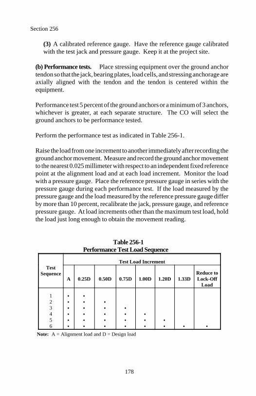
Section 256
178
(3) A calibrated reference gauge. Have the reference gauge calibratedwith the test jack and pressure gauge. Keep it at the project site.
(b) Performance tests. Place stressing equipment over the ground anchortendon so that the jack, bearing plates, load cells, and stressing anchorage areaxially aligned with the tendon and the tendon is centered within theequipment.
Performance test 5 percent of the ground anchors or a minimum of 3 anchors,whichever is greater, at each separate structure. The CO will select theground anchors to be performance tested.
Perform the performance test as indicated in Table 256-1.
Raise the load from one increment to another immediately after recording theground anchor movement. Measure and record the ground anchor movementto the nearest 0.025 millimeter with respect to an independent fixed referencepoint at the alignment load and at each load increment. Monitor the loadwith a pressure gauge. Place the reference pressure gauge in series with thepressure gauge during each performance test. If the load measured by thepressure gauge and the load measured by the reference pressure gauge differby more than 10 percent, recalibrate the jack, pressure gauge, and referencepressure gauge. At load increments other than the maximum test load, holdthe load just long enough to obtain the movement reading.
Table 256-1Performance Test Load Sequence
TestSequence
Test Load Increment
A 0.25D 0.50D 0.75D 1.00D 1.20D 1.33D Lock-OffReduce to
Load
123456
Note: A = Alignment load and D = Design load
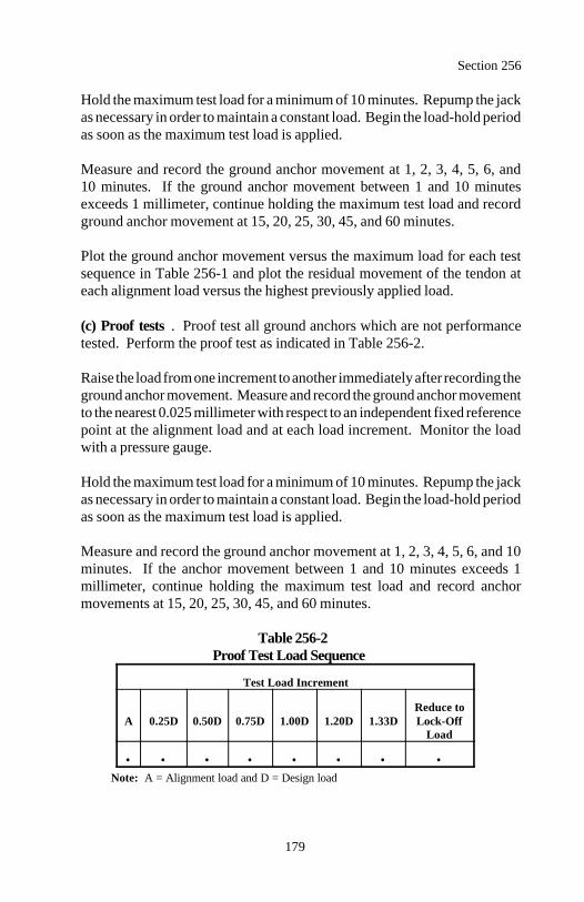
Section 256
179
Hold the maximum test load for a minimum of 10 minutes. Repump the jackas necessary in order to maintain a constant load. Begin the load-hold periodas soon as the maximum test load is applied.
Measure and record the ground anchor movement at 1, 2, 3, 4, 5, 6, and10 minutes. If the ground anchor movement between 1 and 10 minutesexceeds 1 millimeter, continue holding the maximum test load and recordground anchor movement at 15, 20, 25, 30, 45, and 60 minutes.
Plot the ground anchor movement versus the maximum load for each testsequence in Table 256-1 and plot the residual movement of the tendon ateach alignment load versus the highest previously applied load.
(c) Proof tests . Proof test all ground anchors which are not performancetested. Perform the proof test as indicated in Table 256-2.
Raise the load from one increment to another immediately after recording theground anchor movement. Measure and record the ground anchor movementto the nearest 0.025 millimeter with respect to an independent fixed referencepoint at the alignment load and at each load increment. Monitor the loadwith a pressure gauge.
Hold the maximum test load for a minimum of 10 minutes. Repump the jackas necessary in order to maintain a constant load. Begin the load-hold periodas soon as the maximum test load is applied.
Measure and record the ground anchor movement at 1, 2, 3, 4, 5, 6, and 10minutes. If the anchor movement between 1 and 10 minutes exceeds 1millimeter, continue holding the maximum test load and record anchormovements at 15, 20, 25, 30, 45, and 60 minutes.
Table 256-2Proof Test Load Sequence
Test Load Increment
A 0.25D 0.50D 0.75D 1.00D 1.20D 1.33D Lock-OffReduce to
Load
Note: A = Alignment load and D = Design load
Section 256
180
Plot the ground anchor movement versus load for each load increment inTable 256-2.
(d) Lock off. Upon completion of performance and proof tests, reduce theload to the specified lock-off load and transfer the load to the anchoragedevice. After transferring the load and before removing the jack, measure thelift-off load. If the load is not within 10 percent of the specified lock-offload, reset the anchorage and remeasure the lift-off load. Repeat asnecessary.
256.09 Acceptance. Material for ground anchors will be evaluated underSubsections 106.02 and 106.03.
Construction of ground anchors and services will be evaluated under Subsec-tions 106.02 and 106.04.
Installed ground anchors will be evaluated based on one of the followingperformance or proof test results:
(a) After a 10-minute hold, the ground anchor carries the maximum test loadwith less than 1 millimeter of movement between 1 and 10 minutes and thetotal movement at the maximum test load exceeds 80 percent of the the-oretical elastic elongation of the unbonded length.
(b) After a 60-minute hold, the ground anchor carries the maximum test loadwith a creep rate that does not exceed 2-millimeter/log cycle of time and thetotal movement at the maximum test load exceeds 80 percent of thetheoretical elastic elongation of the unbonded length.
Replace all ground anchors with unacceptable performance or proof testresults. Do not retest failed ground anchors.
Measurement
256.10 Measure ground anchors by the each.
Measure performance tests that indicate acceptable installations by the each.

Section 256
181
Payment
256.11 The accepted quantities, measured as provided above, will be paid atthe contract price per unit of measurement for the pay items listed below thatare shown in the bid schedule. Payment will be full compensation for the workprescribed in this Section. See Subsection 109.05.
Payment will be made under:
Pay Item Pay Unit
25601 Ground anchor Each25602 Performance test Each
182
Section 257.) ALTERNATE RETAINING WALLS
Description
257.01 This work consists of constructing various types of retaining walls atthe Contractor's option. The alternate wall types are gabions, crib walls,mechanically stabilized earth walls, permanent ground anchor walls, andreinforced concrete retaining walls.
Material
257.02 Conform to the following Sections:
Crib walls 254Driven piles 551Gabions 253Mechanically stabilized earth walls 255Permanent ground anchors 256Reinforced concrete retaining walls 258Reinforcing steel 554Structural concrete 552
Construction Requirements
257.03 General. The designer/supplier furnishing the proposed wall isresponsible for the stability of the wall. Do not qualify the responsibility forthe design or restrict the use of the drawings or calculations for the proposedalternate. Indemnify the Government from all claims for infringement ofproprietary rights by others without the consent of the patent holders orlicensees.
257.04 Submittal. Submit a proposal using any of the wall types listed.Submit wall type proposals on a site-by-site basis. Different types may be usedat individual sites on the project.
Survey according to Section 152 and verify the limits of the wall installation. Provide drawings of the proposed wall according to Subsection 104.03within 120 days of the notice to proceed and at least 90 days before startingwall construction.
All drawings shall be signed by a licensed professional engineer.
Section 257
183
Include all details, dimensions, quantities, ground profiles, and cross-sectionsnecessary to construct the wall. Submit design calculations on sheets about200 by 300 millimeters in size with the project number, wall location, designa-tion, date of preparation, initials of designer and checker, and page number atthe top of the page.
Provide an index page with the design calculations. The drawings shallinclude, but not be limited to, the following items:
(a) Plan and elevation drawings for each wall containing the following:
(1) A plan view of the wall identifying:
(a) Offset from the construction centerline to the face of the wall at itsbase at all changes in horizontal alignment(b) Limit of widest module, mesh, strip, or anchor(c) Centerline of any drainage structure or drainage pipe behind,passing through, or passing under the wall
(2) An elevation view of the wall identifying:
(a) Elevation at the top of the wall, at all horizontal and vertical breakpoints, and at least every 10 meters along the wall(b) Elevations at the wall base, the top of leveling pads and footings,or the bottom of soldier piles(c) Wall batter(d) Distance along the face of the wall to all steps in the wall base,footings, leveling pads, or lagging(e) Type of panel or depth of module or lagging(f) Length and type of mesh, strips, or anchors(g) Distance along the face of the wall to where changes in length ofthe mesh, strips, or anchors occur(h) Original and final ground line
(3) General notes for constructing the wall.
(4) Horizontal and vertical curve data affecting the wall. Match lines orother details to relate wall stationing to centerline stationing.
(5) A listing of the summary of quantities on the elevation drawing ofeach wall.
Section 257
184
(b) Dimensions and schedules of all reinforcing steel including reinforcingbar bending details, dowels, and/or studs for attaching the facing.
(c) Details and dimensions for foundations and leveling pads including stepsin the footings or leveling pads.
(d) Details and dimensions for all:
(1) Panels, modules, soldier piles, and lagging necessary to construct theelement
(2) Reinforcing steel in the element
(3) Location of mesh, strip attachment, or anchor devices embedded in thepanels
(4) Anchors and soldier piling including the spacing and size of piles andthe spacing and angle of anchors
(e) Details for constructing walls around drainage facilities.
(f) Details for terminating walls and adjacent slope construction.
(g) Architectural treatment details.
(h) Design notes including an explanation of any symbols and computerprograms used in the design of the walls. Specify the factors of safety forsliding, pullout, and overturning. Specify the bearing pressure beneath thewall footing, stabilized earth mass, or soldier piles.
(i) Verification of design criteria for the site specific wall locations with testprocedures, results, and interpretations. Include results from creep,durability, construction induced damage, and junction strength tests.
(j) Other design calculations.
Process all submissions through the Contractor unless the Contractor giveswritten permission for the wall designer/supplier and the CO to communicatedirectly.
Section 257
185
Submit 3 sets of the wall drawings with the initial submission. One set will bereturned with any indicated corrections. If revisions are necessary, make thenecessary corrections and resubmit 3 revised sets.
When the drawings are accepted, furnish 5 sets and a mylar sepia set of thedrawings.
257.05 Construction. Construct the wall according to the accepted drawingsand the following Sections, as applicable:
(a) Gabions . Section 253.
(b) Crib walls . Section 254.
(c) Mechanically stabilized earth walls. Section 255.
(d) Permanent ground anchor walls . Sections 256, 551, and 552.
(e) Reinforced concrete retaining walls. Section 258.
Revise the drawings when plan dimensions are revised due to field conditionsor for other reasons.
257.06 Acceptance. Material for alternate retaining walls will be evaluat-ed under Subsection 106.02, 106.03, or 106.04 according to the applicable sec-tions listed in Subsection 257.05.
Construction of alternate retaining walls and services will be evaluated underSubsections 106.02 and 106.04 according to the applicable sections listed inSubsection 257.05.
Structure excavation and backfill will be evaluated under Section 209.
Measurement
257.07 Measure alternate retaining walls by the lump sum.
Measure foundation fill under Section 208.
Section 257
186
Payment
257.08 The accepted quantities, measured as provided above, will be paid atthe contract price per unit of measurement for the pay item listed below that isshown in the bid schedule. Payment will be full compensation for the workprescribed in this Section. See Subsection 109.05.
When plan dimensions are changed by the CO during construction to accountfor field conditions, the lump sum price of the wall will be adjusted by applyinga calculated per square meter cost adjustment factor to the added or decreasedwall front face area resulting from the change.
The adjustment factor will be determined by dividing the lump sum price bidfor each wall by its estimated area shown in the pay item.
The alternate retaining wall lump sum will be paid based on the progress of thework under this Section.
Payment will be made under:
Pay Item Pay Unit
25701 Alternate retaining wall (location) , Lump sum( (estimated) m²)
187
Section 258.— REINFORCED CONCRETERETAINING WALLS
Description
258.01 This work consists of constructing reinforced concrete retaining walls.
Material
258.02 Conform to the following Sections and Subsections:
Concrete 552Forms and falsework 562Joint fillers and sealants 712.01Reinforcing steel 709.01Structural backfill 704.04Tie bars, dowel bars, and hook bolts 709.01
Construction Requirements
258.03 General. Survey according to Section 152 and verify the limits of thewall installation. Prepare and submit forms and falsework drawings accordingto Section 562. Perform the work under Section 209.
258.04 Reinforcing Steel. Submit all order lists and bending diagramsaccording to Subsections 104.03 and 554.03. Fabricate reinforcing steelaccording to Subsection 554.05. Ship and protect material according toSubsections 554.04 and 554.06. Place, fasten, and splice reinforcing steelaccording to Subsections 554.08 and 554.09.
258.05 Structural Concrete. Design concrete mixture according to Sub-section 552.03. Store, handle, batch, and mix material and deliver concreteaccording to Subsections 552.04 through 552.08. Provide quality controlaccording to Section 153 and Subsection 552.09. Construct wall according toSubsections 552.10 through 552.16.
Section 258
188
258.06 Backfilling. Backfill the area behind the wall with structural backfillaccording to Subsection 209.10. Compact each layer according to Subsection209.11, except use an approved lightweight mechanical or vibratory compactorwithin one meter of the wall.
258.07 Acceptance. Reinforced concrete retaining wall material, construc-tion, and services will be evaluated as follows:
Survey work will be evaluated under Section 152.
Forms and falsework drawings will be evaluated under Section 562.
Structure excavation and backfill will be evaluated under Section 209.
Concrete will be evaluated under Section 552.
Reinforcing steel will be evaluated under Section 554.
Material for joint fillers, sealants, tie bars, dowel bars, and hook bolts will beevaluated under Subsections 106.02 and 106.03.
Measurement
258.08 Measure reinforced concrete retaining walls by the cubic meter in thestructure, by the square meter, or by the meter. Include the volume of footingsin the cubic meter measurement. Determine the square meter area from thelength of the front wall face and the height excluding footings. Determine themeter length along the top of the wall.
Measure foundation fill under Section 208.
Payment
258.09 The accepted quantities, measured as provided above, will be paid atthe contract price per unit of measurement adjusted according to Subsection106.05 for the pay items listed below that are shown on the bid schedule. Pay-ment will be full compensation for the work prescribed in this Section. SeeSubsection 109.05.
Section 258
189
The accepted quantities of reinforced concrete retaining wall will be paid forat the contract unit bid price multiplied by an adjusted pay factor (PFa)determined as follows:
PFa = 1 - 0.5 (1-PF)
Where
PF = Pay factor for concrete as determined under Section 552.
Payment will be made under:
Pay Item Pay Unit
25801 Reinforced concrete retaining wall Square meter25802 Reinforced concrete retaining wall Meter25803 Reinforced concrete retaining wall Cubic meter


191
DIVISION 300Aggregate Courses
192
Section 301.) UNTREATED AGGREGATE COURSES
Description
301.01 This work consists of constructing one or more courses of aggregateon a prepared surface.
Subbase and base aggregate grading is designated as shown in Table 703-2.
Material
301.02 Conform to the following Subsections:
Aggregate 703.05Water 725.01
Construction Requirements
301.03 General. Prepare the surface on which the aggregate course is placedaccording to Section 204 or 303 as applicable.
After a representative quantity of aggregate is produced, submit proposedtarget values for the appropriate sieve sizes along with a representative 150-kilogram sample at least 14 days before incorporating the aggregate into thework.
Set target values within the gradation ranges shown in Table 703-2 or 703-3 forthe required grading.
301.04 Mixing and Spreading. Determine the optimum moisture contentaccording to AASHTO T 180 method D. Mix the aggregate and adjust themoisture content to obtain a uniform mixture with a moisture content within 2percent of the optimum moisture content. Spread and shape the mixture on theprepared surface in a uniform layer.
Do not place the mixture in a layer exceeding 150 millimeters in compactedthickness. When more than one layer is necessary, compact each layeraccording to Subsection 301.05 before placing the next layer. Route haulingequipment uniformly over the full width of the surface to minimize rutting oruneven compaction.
Section 301
193
301.05 Compacting. Determine the maximum density of the mixtureaccording to AASHTO T 180 method D.
Compact each layer full width. Roll from the sides to the center, parallel to thecenterline of the road. Along curbs, headers, walls, and all places notaccessible to the roller, compact the material with approved tampers orcompactors.
Compact each layer to at least 95 percent of maximum density. Determine theinplace density and moisture content according to AASHTO T 238 andAASHTO T 239 or other approved test procedures.
301.06 Surface Tolerance. If grade finishing stakes are required, finish thesurface to within ±10 millimeters from staked line and grade elevation.
If grade finishing stakes are not required, shape the surface to the requiredtemplate and check the surface with a 3-meter straightedge. Defective areasare surface deviations in excess of 15 millimeters in 3 meters between any twocontacts of the straightedge with the surface.
Correct all defective areas by loosening the material, adding or removingmaterial, reshaping, and compacting.
301.07 Maintenance. Maintain the aggregate course to the correct line,grade, and cross-section by blading, watering, rolling, or any combinationthereof until placement of the next course. Correct all defects according toSubsection 301.06.
301.08 Acceptance. Aggregate gradation and surface course plasticity indexwill be evaluated under Subsection 106.05. Other aggregate quality propertieswill be evaluated under Subsections 106.02 and 106.04. See Table 301-1 forminimum sampling and testing requirements.
(a) Aggregate gradation. The upper and lower specification limits are theapproved target values plus or minus the allowable deviations shown inTables 703-2 and 703-3. See Table 301-1 for the acceptance qualitycharacteristic categories.
(b) Plasticity index. The upper and lower specification limits for surfacecourses are shown in Table 703-3. See Table 301-1 for the acceptancequality characteristic category.
Section 301
194
Construction of untreated aggregate courses will be evaluated under Subsec-tions 106.02 and 106.04. See Table 301-1 for minimum sampling and testingrequirements.
Preparation of the surface on which the aggregate course is placed will be eval-uated under Section 204 or 303 as applicable.
Measurement
301.09 Measure aggregate by the metric ton, by the square meter, or by thecubic meter in the hauling vehicle. Measure square meter width horizontallyto include the top of aggregate width and allowable curve widening. Measurethe square meter length horizontally along the centerline of the roadway.
Payment
301.10 The accepted quantities, measured as provided above, will be paid atthe contract price per unit of measurement adjusted according to Subsection106.05 for the pay items listed below that are shown in the bid schedule.Payment will be full compensation for the work prescribed in this Section. SeeSubsection 109.05.
Payment will be made under:
Pay Item Pay Unit
30101 Aggregate base grading ___ Metric ton30102 Aggregate base grading ___, ___ millimeter depth Square meter30103 Aggregate base grading ___ Cubic meter30104 Subbase grading ___ Metric ton30105 Subbase grading ___, ___ millimeter depth Square meter30106 Subbase grading ___ Cubic meter30107 Aggregate surface course Metric ton30108 Aggregate surface course, ___ millimeter depth Square meter30109 Aggregate surface course Cubic meter
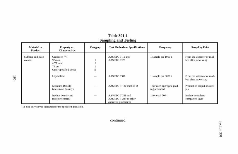
Section 301
195
Table 301-1Sampling and Testing
Material orProduct
Property or Characteristic
Category Test Methods or Specifications Frequency Sampling Point
Subbase and Basecourses
Gradation )(1)
9.5 mm4.75 mm75 µmOther specified sieves
Liquid limit
Moisture-Density (maximum density)
Inplace density and moisture content
IIIII
—
—
—
AASHTO T 11 and AASHTO T 27
AASHTO T 89
AASHTO T 180 method D
AASHTO T 238 and AASHTO T 239 or other approved procedures
1 sample per 1000 t
1 sample per 3000 t
1 for each aggregate grad-ing produced
1 for each 500 t
From the windrow or road-bed after processing
From the windrow or road-bed after processing
Production output or stock-pile
Inplace completed compacted layer
(1) Use only sieves indicated for the specified gradation.
continued
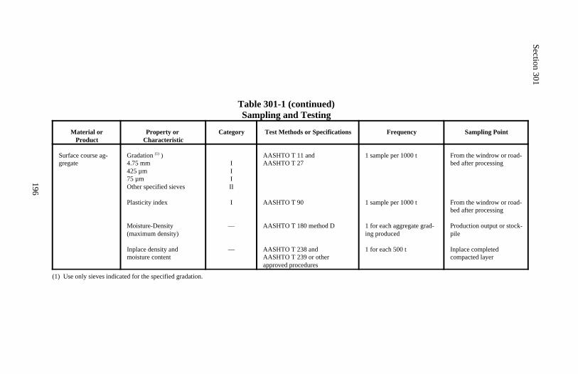
Section 301
196
Table 301-1 (continued)Sampling and Testing
Material orProduct
Property or Characteristic
Category Test Methods or Specifications Frequency Sampling Point
Surface course ag-gregate
Gradation )(1)
4.75 mm425 µm75 µmOther specified sieves
Plasticity index
Moisture-Density (maximum density)
Inplace density and moisture content
IIIII
I
—
—
AASHTO T 11 and AASHTO T 27
AASHTO T 90
AASHTO T 180 method D
AASHTO T 238 and AASHTO T 239 or other approved procedures
1 sample per 1000 t
1 sample per 1000 t
1 for each aggregate grad-ing produced
1 for each 500 t
From the windrow or road-bed after processing
From the windrow or road-bed after processing
Production output or stock-pile
Inplace completed compacted layer
(1) Use only sieves indicated for the specified gradation.
197
Section 302.) TREATED AGGREGATE COURSES
Description
302.01 This work consists of constructing one or more courses of an aggregateand cement mixture or an aggregate, fly ash, lime, and/or cement (AFLC)mixture on a prepared roadbed.
Treated aggregate courses are designated as cement or AFLC.
Aggregate grading is designated as shown in Table 703-2.
Material
302.02 Conform to the following Subsections:
Aggregate 703.05Blotter 703.13Chemical admixture (set-retarding) 711.03Emulsified asphalt 702.03Fly ash 725.04Lime 725.03Portland cement 701.01Water 725.01
Construction Requirements
302.03 Proportioning. Submit a treated aggregate course mix design 30 daysbefore production.
Provide a minimum average compressive strength of 3.45 megapascals with nosingle test lower than 2.75 megapascals. Mold, cure, and test samples of theAFLC mixture according to ASTM C 593, parts 10 and 11 except revise thecuring period from 7 to 28 days at 38±2 C.
For aggregate and cement mixtures, meet the design parameters in Table 302-1.
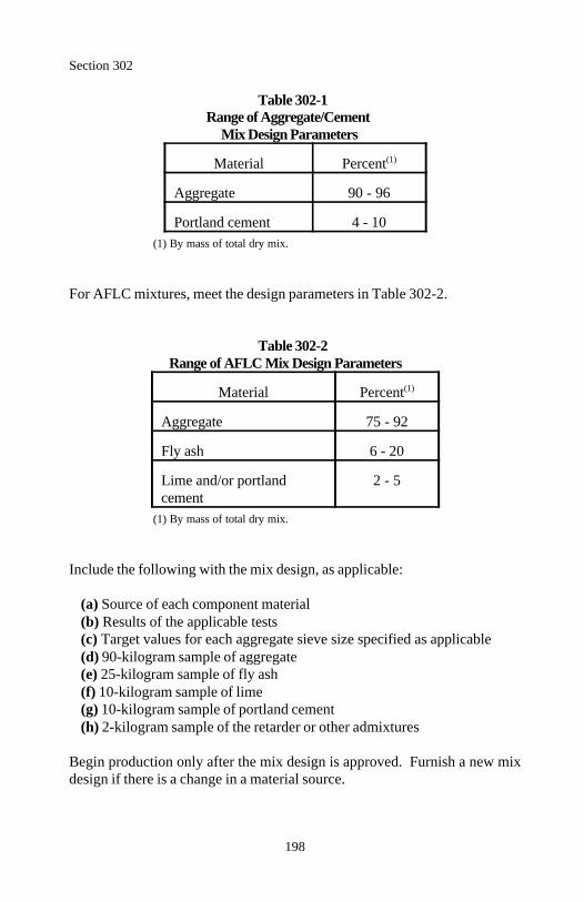
Section 302
198
Table 302-1Range of Aggregate/Cement
Mix Design Parameters
Material Percent(1)
Aggregate 90 - 96
Portland cement 4 - 10(1) By mass of total dry mix.
For AFLC mixtures, meet the design parameters in Table 302-2.
Table 302-2Range of AFLC Mix Design Parameters
Material Percent(1)
Aggregate 75 - 92
Fly ash 6 - 20
Lime and/or portland 2 - 5cement
(1) By mass of total dry mix.
Include the following with the mix design, as applicable:
(a) Source of each component material(b) Results of the applicable tests(c) Target values for each aggregate sieve size specified as applicable(d) 90-kilogram sample of aggregate(e) 25-kilogram sample of fly ash(f) 10-kilogram sample of lime(g) 10-kilogram sample of portland cement(h) 2-kilogram sample of the retarder or other admixtures
Begin production only after the mix design is approved. Furnish a new mixdesign if there is a change in a material source.
Section 302
199
302.04 General. Store chemical additives and admixtures in closed, weath-erproof containers. Prepare the surface on which the treated aggregate courseis placed according to Section 204 or 303 as applicable. Determine theoptimum moisture content according to AASHTO T 180 method D.
302.05 Mixing. Do not begin mixing operations when the atmospherictemperature is expected to fall below 4 C within 48 hours. Do not place atreated aggregate course when the underlying surface is frozen, muddy, orwhen it is raining or snowing.
Mix the components with suitable equipment until a uniform mixture isobtained. During mixing, add sufficient water to obtain the optimum moisturecontent for compaction plus 2 percent.
Equip the mixer with batching or metering devices for proportioning thecomponents either by mass or volume. Maintain the accuracy of the amountsof aggregate, chemical additives, and water (based on total dry mass) within thefollowing tolerances:
Aggregate ±2.0% by massFly ash ±1.5% by massLime or cement ±0.5% by massRetarder or other additive ±2.0% by massWater ±2.0% by mass
A retarder may be used to slow initial set for a maximum of 2 hours. Dissolveretarder in water and uniformly add the solution to the mixture.
When a central plant is used, transport the mixture in vehicles that maintainmoisture content and prevent segregation and loss of the fine material.
302.06 Placing, Compacting, and Finishing. Place, compact, and finish thetreated aggregate course according to Subsections 301.04, 301.05, and 301.06.Maintain the moisture content (±2 percent of optimum) during placing and fin-ishing.
Do not leave any treated aggregate that has not been compacted undisturbedfor more than 30 minutes. Complete the compaction and finishing within1 hour (longer with a retarder) from the time water is added to the mixture.Make the compacted surface smooth, dense, and free of compaction planes,ridges, or loose material.
Section 302
200
If the time between placing adjacent partial widths exceeds 30 minutes, providea construction joint.
302.07 Construction Joints. For lime and fly ash mixtures, tie each day'soperation into the completed work of the previous day by remixing approxi-mately 0.5 meters of the completed course before processing additionalsections. Add 50 percent of the original amount of lime or fly ash to the re-mixed material.
For cement mixtures or when a lime or fly ash mixture remains undisturbed formore than 24 hours, make a transverse construction joint by cutting back intothe completed work to form an approximately vertical face.
302.08 Curing. Do not allow traffic on the treated aggregate course. Keepthe completed layer or course continuously moist until the next layer or courseis placed. Apply water under pressure through a spray bar equipped withnozzles producing a fine, uniform spray. Place and compact the next layer orcourse within 7 days after compacting and finishing the treated aggregatecourse.
Placement of the next course may be deferred up to 21 days by sealing thesurface with rapid setting emulsified asphalt. Do not seal intermediate layersof a course. Keep surface continuously moist for at least 7 days after com-pacting and finishing. After the 7 days, apply undiluted CRS-2 or RS-2 emulsi-fied asphalt at a rate of 1.1 liters per square meter according to Section 409.Provide a continuous film over the surface. If the surface is opened to publictraffic, furnish and apply blotter according to Section 411.
If the treated aggregate course looses stability, density, or finish beforeplacement of the next course or acceptance of the work, reprocess, recompact,and add additives as necessary to restore the strength of the damaged material.Reapply the emulsified asphalt seal where the continuous film is damaged.
302.09 Acceptance. Fly ash, lime, cement, and chemical admixtures will beevaluated under Subsections 106.02 and 106.03. Emulsified asphalt will beevaluated under Subsections 106.03 and 702.09.
Section 302
201
Aggregate gradation will be evaluated under Subsection 106.05. The aggregategradation upper and lower specification limits are the approved target valuesplus or minus the allowable deviations shown in Table 703-2. Other aggregatequality properties will be evaluated under Subsections 106.02 and 106.04. SeeTable 302-3 for the acceptance quality characteristic categories and minimumsampling and testing requirements. Construction of treated aggregate courses will be evaluated under Subsections106.02 and 106.04. See Table 302-3 for minimum sampling and testing re-quirements.
Preparation of the surface on which the treated aggregate course is placed willbe evaluated under to Section 204 or 303 as applicable.
Emulsified asphalt seal will be evaluated under Section 409.
Blotter will be evaluated under Section 411.
Measurement
302.10 Measure treated aggregate course by the metric ton or by the squaremeter. Measure square meter width horizontally to include the top of aggregatewidth and allowable curve widening. Measure the square meter length hori-zontally along the centerline of the roadway.
Measure fly ash, lime, and cement by the metric ton.
Measure emulsified asphalt under Section 409.
Measure blotter under Section 411.
Payment
302.11 The accepted quantities, measured as provided above, will be paid atthe contract price per unit of measurement adjusted in according to Subsection 106.05 for the pay items listed below that are shown in the bid schedule.Payment will be full compensation for the work prescribed in this Section. SeeSubsection 109.05.

Section 302
202
Payment will be made under:
Pay Item Pay Unit
30201 ______ treated aggregate course grading ___ Metric ton30202 ______ treated aggregate course grading ___, Square meter
___ millimeter depth30203 Cement Metric ton30204 Fly ash Metric ton30205 Lime Metric ton

Section 302
203
Table 302-3Sampling and Testing
Material orProduct
Property or Characteristic
Category Test Methods or Specifications Frequency Sampling Point
Aggregate Gradation ) (1)
9.5 mm4.75 mm75 µmOther specified sieves
Liquid limit
IIIII
—
AASHTO T 11 and AASHTO T 27
AASHTO T 89
1 sample per 1000 t
1 sample per 3000 t
From the windrow or road-bed after processing
From the windrow or road-bed after processing
Mixture Moisture-Density (maximum density)
Inplace density and moisture content
—
—
AASHTO T 180 method D
AASHTO T 238 and AASHTO T 239 or other approved procedures
1 for each aggregate grad-ing produced
1 for each 500 t
Processed material beforeincorporated into the work
Inplace completed compacted layer
(1) Use only sieves indicated for the specified gradation.
204
Section 303.) ROAD RECONDITIONING
Description
303.01 This work consists of reconditioning graded roadbeds, aggregatesurfaces, or asphalt surfaces. This work also includes cleaning and reshapingshoulders, ditches, and culvert inlets and outlets.
Material
303.02 Conform to the following Sections and Subsection:
Crack sealant 414Crushed aggregate 308Minor cold asphalt mix 417Minor crushed aggregate 308Minor hot asphalt concrete 402Water 725.01
Construction Requirements
303.03 General. Remove all slide material, vegetation, and other debris fromthe existing roadbed or surface including parking areas, turnouts, otherwidened areas, shoulders, ditches, and culvert inlets and outlets. Clean andreshape ditches and culvert inlets and outlets as required. Dispose of materialremoved according to Section 203.05.
303.04 Graded Roadbed. Cut to grade any high areas in the roadbed andhaul and deposit the resulting material in low areas. Construct embankmentsto bring the width and surface of the roadbed to finished subgrade accordingto Subsection 204.10. Remove all organic, deleterious, or oversize materiallarger than 150 millimeters from the top 150 millimeters of the roadbed.
Repair soft and unstable areas according to Subsection 204.07. Dispose ofexcess material according to Subsection 204.14.
Section 303
205
303.05 Aggregate Surfaces. Repair soft and unstable areas according toSubsection 204.07. Repair the aggregate surface according to Subsection301.07.
303.06 Asphalt Surfaces. Recondition asphalt surfaces as follows:
(a) Patching. Remove and dispose of unsuitable material that shows evi-dence of distress, excess asphalt material, or settlement in the subgrade.Patch the areas with approved material that conforms to and is compatiblewith the adjacent pavement structure. Perform the patch work according toSection 308, 402, 417, or other sections as applicable for the layer or coursesbeing repaired.
(b) Crack sealing. Clean and seal cracks in the existing asphalt surfaceaccording to Subsection 414.05.
(c) Preleveling. Correct surface irregularities exceeding 150 millimeters indepth with a specified aggregate. Place and compact the aggregate accordingto Subsections 301.04 and 301.05.
Prelevel other dips, depressions, sags, excessive or nonexistent crown, orother surface irregularities with asphalt concrete according to Section 402.Spread and compact the asphalt concrete in layers parallel to the grade linenot to exceed 50 millimeters in compacted depth.
303.07 Finishing Road Surfaces.
(a) Graded roadbeds. Blade, shape, compact, and finish the roadbed,including parking areas, turnouts, and other widened areas. Correctirregularities in the surface by scarifying the defective area and reworking.Compact according to Subsection 204.11. Finish the roadbed to the requiredline, grade, elevation, and cross-section.
(b) Aggregate surfaces. Perform the work under Subsection 303.07(a).Finish the surface according to Subsection 301.06. Compact the surfaceaccording to Subsection 301.05.
Section 303
206
(c) Asphalt surfaces. Clean the existing surface of all loose material, dirt,or other deleterious substances by approved methods.
303.08 Scarification. When required by the contract, scarify the material tothe designated depth and width. Pulverize all lumps to a size one and one halftimes the maximum sized aggregate or to 40 millimeters, whichever is greater.Mix, spread, compact, and finish the material according to Section 301.
303.09 Acceptance. Material for road reconditioning will be evaluated underthe applicable section furnished.
Road reconditioning will be evaluated under Subsection 106.02 and 106.04.
Roadbed finishing will be evaluated under Section 204.
Aggregate surfaces will be evaluated under Section 301 or 308.
Asphalt surfaces will be evaluated under Section 402 or 417.
Crack sealing will be evaluated under Section 414.
Measurement
303.10 Measure road reconditioning by the kilometer or by the square meter.Measure the square meter area on a horizontal plane. Measure to theintersection of the roadway with natural ground (approximate slope stakelocation). Do not measure isolated areas less than 20 square meters forpayment.
Measure removal and disposal of unsuitable material under Section 203.
Measure crack sealing under Section 414.
Measure aggregate for patching and leveling under Section 308.
Measure asphalt material for patching and leveling under Section 402 or 417.
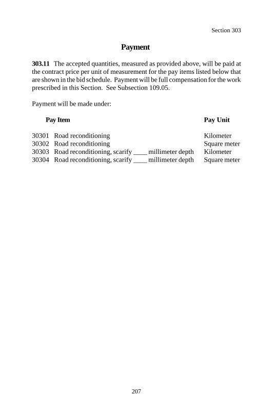
Section 303
207
Payment
303.11 The accepted quantities, measured as provided above, will be paid atthe contract price per unit of measurement for the pay items listed below thatare shown in the bid schedule. Payment will be full compensation for the workprescribed in this Section. See Subsection 109.05.
Payment will be made under:
Pay Item Pay Unit
30301 Road reconditioning Kilometer30302 Road reconditioning Square meter30303 Road reconditioning, scarify ____ millimeter depth Kilometer30304 Road reconditioning, scarify ____ millimeter depth Square meter
208
Section 304.) AGGREGATE STABILIZATION
Description
304.01 This work consists of processing and incorporating fly ash, lime, orportland cement into the upper layer of a previously constructed aggregatecourse.
Material
304.02 Conform to the following Subsections:
Blotter 703.13Chemical admixtures (set-retarding) 711.03Emulsified asphalt 702.03Fly ash 725.04Lime 725.03Portland cement 701.01Water 725.01
Construction Requirements
304.03 General. Store chemical additives and admixtures in closed, we-atherproof containers. Recondition the aggregate course according to Sub-sections 303.03 and 303.05. Scarify the aggregate course to a depth of 100millimeters according to Subsection 303.08. Size and shape the scarifiedaggregate to a windrow or blanket that is suitable for mixing. Determine theoptimum moisture content and maximum density according to AASHTO T 180method D.
304.04 Application. Apply additives when the scarified aggregate is at least3 percent below optimum moisture content and at least 4 C. Do not applywhen excessive additive is lost to washing or blowing or when the air tem-perature is expected to fall below 4 C within 48 hours.
Apply additives at the required rates by one of the following methods:
(a) Dry method. Uniformly apply the additives with an approved spreader.A motor grader is not an approved spreader. Apply water using approvedmethods to obtain the proper moisture content for mixing and compaction.
Section 304
209
(b) Slurry method. Mix additives with water and apply as a thin watersuspension or slurry using either trucks with approved distributors or rotarymixers. Equip the distributor truck or rotary mixer tank with an agitator tokeep the additives suspended in water. Make successive passes over thematerial to obtain the moisture and additive content for mixing andcompacting.
304.05 Mixing. Mix material to obtain a homogeneous friable mixture.
(a) Lime and fly ash mixtures. Add water and thoroughly mix to adjust themoisture content of the mixture to the optimum moisture content plus neces-sary hydration moisture. Hydration moisture is 1.5 percent for each percentof additive in the mixture. Complete the mixing within 6 hours of additiveapplication. Cure the mixture for 2 to 4 days by keeping it moist.
After curing, remix the mixture until 95 percent of all the mixture, exceptrock, passes a 45 millimeter sieve and at least 50 percent of the mixturepasses a 4.75 millimeter sieve when tested according to AASHTO T 27, ina nondried condition. Retarders may be added.
(b) Cement mixtures. Add water and thoroughly mix to adjust the moisturecontent of the mixture to 2 percent above the optimum moisture content.Complete the mixing within 2 hours of cement application.
Adjust the moisture content of the mixture to within 2 percent of the optimummoisture content.
304.06 Compaction and Finishing. Immediately after mixing, spread andcompact the mixture to at least 95 percent of the maximum density. Determinethe inplace density and moisture content according to AASHTO T 238 andAASHTO T 239 or other approved test procedures. Finish the stabilizedaggregate so it is smooth and suitable for placing another course.
If the time between compacting adjacent partial widths exceeds 30 minutes orwhen tying into the previous work, provide a construction joint according toSubsection 302.07.
Section 304
210
304.07 Curing. Do not allow traffic on the stabilized aggregate. Keep theaggregate continuously moist until the next course is placed. Apply waterunder pressure through a spray bar equipped with nozzles producing a fine,uniform spray. Place the next course within 7 days after compacting andfinishing the stabilized aggregate.
Placement of the next course may be deferred up to 21 days by sealing thesurface with a rapid setting emulsified asphalt. Keep the surface continuouslymoist for at least 7 days after compacting and finishing. After the 7 days, applyundiluted CRS-2 or RS-2 emulsified asphalt at a rate of 1.1 liters per squaremeter according to Section 409. Provide a continuous film over the surface.If the surface is opened to public traffic, furnish and apply blotter according toSection 411.
If the stabilized aggregate looses stability, density, or finish before placementof the next course, reprocess, recompact, and add additives as necessary torestore the strength of the damaged material. Reapply the emulsified asphaltseal where the continuous film is damaged.
304.08 Acceptance. Material for blotter, chemical admixtures (retarder), flyash, lime, portland cement, and water will be evaluated under Subsections106.02 and 106.03. Emulsified asphalt will be evaluated under Subsections106.03 and 702.09.
Aggregate stabilization work will be evaluated under Subsections 106.02 and106.04. See Table 304-1 for minimum sampling and testing require-ments.
Reconditioning of the aggregate course will be evaluated under Section 303.
Emulsified asphalt seal will be evaluated under Section 409.
Blotter will be evaluated under Section 411.
Measurement
304.09 Measure aggregate stabilization by the kilometer or by the squaremeter. Measure square meter width horizontally to include the top of aggregatewidth and allowable curve widening. Measure the square meter length hori-zontally along the centerline of the roadway.
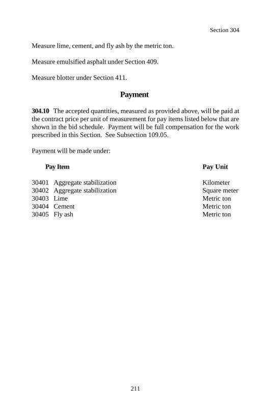
Section 304
211
Measure lime, cement, and fly ash by the metric ton.
Measure emulsified asphalt under Section 409.
Measure blotter under Section 411.
Payment
304.10 The accepted quantities, measured as provided above, will be paid atthe contract price per unit of measurement for pay items listed below that areshown in the bid schedule. Payment will be full compensation for the workprescribed in this Section. See Subsection 109.05.
Payment will be made under:
Pay Item Pay Unit
30401 Aggregate stabilization Kilometer30402 Aggregate stabilization Square meter30403 Lime Metric ton30404 Cement Metric ton30405 Fly ash Metric ton
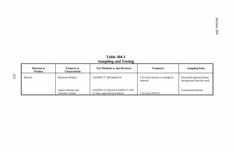
Section 304
212
Table 304-1Sampling and Testing
Material orProduct
Property or Characteristic
Test Methods or Specifications Frequency Sampling Point
Mixture Moisture-Density
Inplace density and moisture content
AASHTO T 180 method D
AASHTO T 238 and AASHTO T 239or other approved procedures
1 for each mixture or change inmaterial
1 for each 2500 m2
Processed material beforeincorporated into the work
Compacted material
213
Section 305.) AGGREGATE-TOPSOIL COURSE
Description
305.01 This work consists of furnishing and placing an aggregate, topsoil, andseed mixture on a prepared shoulder or other surface.
Material
305.02 Conform to the following Subsections:
Aggregate 703.14Seed 713.04Topsoil 713.01Water 725.01
Construction Requirements
305.03 Preparing Surface. Complete the adjoining pavement before placingan aggregate-topsoil mixture on the shoulder. Scarify the area where themixture is to be placed to a depth of 75 millimeters. Reduce all clods and sodto a maximum size of 100 millimeters.
305.04 Mixing, Placing, and Compacting. Furnish a mixture of 50±10percent aggregate and 50±10 percent topsoil by volume with sufficient waterfor compaction.
Mix the components into a uniform mixture. Spread the mixture on theprepared surface in a uniform layer. Shape the mixture to the line, grade, andcross-section. Remove all clods and stones greater than 50 millimeters indiameter. Before compaction, dry seed the mixture surface at a rate of 85kilograms per hectare according to Section 625.
Determine maximum density of the mixture according to AASHTO T 99 meth-od C. Compact the mixture to at least 90 percent of maximum density.Determine the inplace density according to AASHTO T 238 or other approvedtest procedures. After compaction, dry seed the surface again at a rate of 85kilograms per hectare.
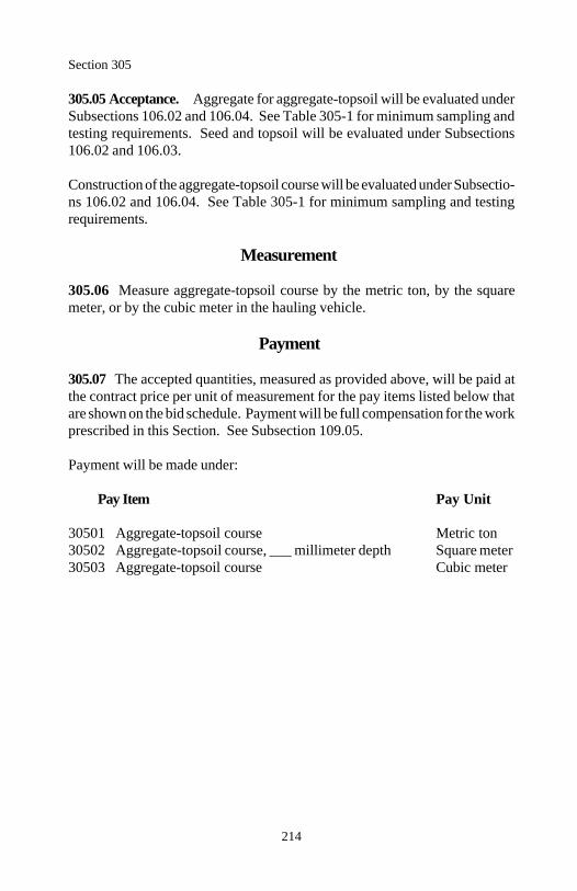
Section 305
214
305.05 Acceptance. Aggregate for aggregate-topsoil will be evaluated underSubsections 106.02 and 106.04. See Table 305-1 for minimum sampling andtesting requirements. Seed and topsoil will be evaluated under Subsections106.02 and 106.03.
Construction of the aggregate-topsoil course will be evaluated under Subsectio-ns 106.02 and 106.04. See Table 305-1 for minimum sampling and testingrequirements.
Measurement
305.06 Measure aggregate-topsoil course by the metric ton, by the squaremeter, or by the cubic meter in the hauling vehicle.
Payment
305.07 The accepted quantities, measured as provided above, will be paid atthe contract price per unit of measurement for the pay items listed below thatare shown on the bid schedule. Payment will be full compensation for the workprescribed in this Section. See Subsection 109.05.
Payment will be made under:
Pay Item Pay Unit
30501 Aggregate-topsoil course Metric ton30502 Aggregate-topsoil course, ___ millimeter depth Square meter30503 Aggregate-topsoil course Cubic meter
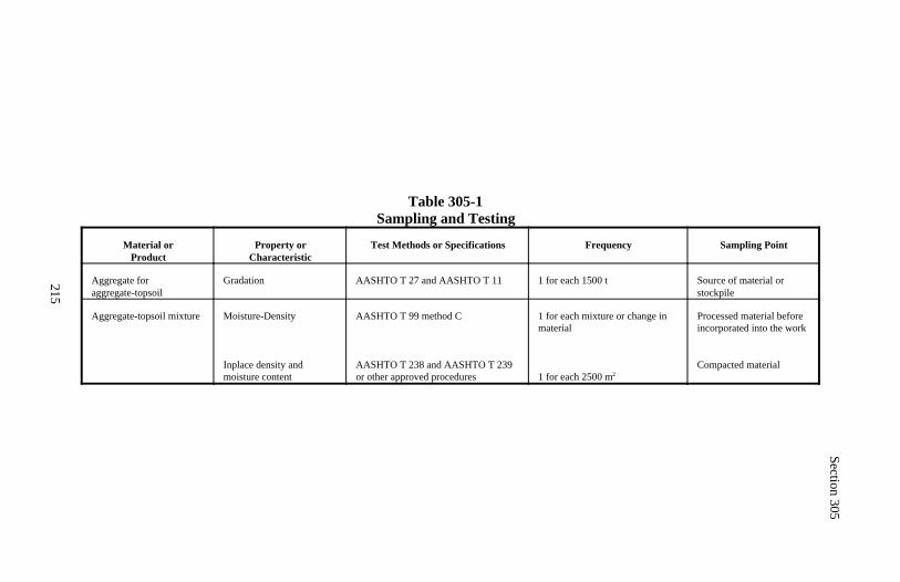
Section 305
215
Table 305-1Sampling and Testing
Material orProduct
Property orCharacteristic
Test Methods or Specifications Frequency Sampling Point
Aggregate foraggregate-topsoil
Gradation AASHTO T 27 and AASHTO T 11 1 for each 1500 t Source of material orstockpile
Aggregate-topsoil mixture Moisture-Density
Inplace density andmoisture content
AASHTO T 99 method C
AASHTO T 238 and AASHTO T 239or other approved procedures
1 for each mixture or change inmaterial
1 for each 2500 m2
Processed material beforeincorporated into the work
Compacted material
216
Section 306.) DUST PALLIATIVE
Description
306.01 This work consists of furnishing and applying one or more applicationsof a dust palliative on a prepared surface.
Material
306.02 Conform to the following Subsections:
Calcium chloride 725.02Emulsified asphalt 702.03Lignin sulfonate 725.20Magnesium chloride 725.02Water 725.01
Construction Requirements
306.03 General. Use distributor equipment conforming to Subsection 409.04,except heating capability is not required. Equip the distributor with a hose andnozzle for areas inaccessible to the distributor and for touch-up work. Do notapply a dust palliative when the weather is foggy or rainy or when rain is antici-pated within 24 hours of application. Apply when the ambient air temperatureis 4 C or above.
Protect the surfaces of structures and trees from splatter or marring duringapplication. Use multiple applications at a reduced rate if necessary to preventrunoff. Do not discharge dust palliative into streams.
306.04 Preparation and Application.
(a) Emulsified asphalt. Prepare the surface according to Subsection 303.07.
When a slow setting emulsified asphalt is used, dilute it with water until theemulsion contains 25±10 percent residual asphalt. Before application, ap-proval of the exact proportions is required. Thoroughly blend the emulsifiedasphalt with the added water before application. Apply according to Subsec-tion 409.08.
Section 306
217
(b) Lignin sulfonate, calcium chloride, or magnesium chloride. Preparethe roadbed by blading and shaping to leave 25 to 50 millimeters of relativelyloose material on the surface. Water the loose material so it is visibly moist.
When lignin sulfonate is used, dilute it with water until the mixture contains40±10 percent lignin sulfonate by volume. When calcium chloride is used,make a water solution that contains 32±5 percent chloride by mass. Beforeapplication, approval of the exact proportions is required. Thoroughly mixthe components before application.
When magnesium chloride is used, apply the brine when the ambient airtemperature is 15 C or above.
Apply at a rate of 1.4 to 2.7 liters per square meter as approved. Compactthe surface.
306.05 Acceptance. Dust palliative material (emulsified asphalt, lignin sulfo-nate, calcium chloride, and magnesium chloride) will be evaluated under Sub-section 106.03.
When lignin sulfonate is furnished, the commercial certification shall includethe following information for each shipment: date, identification number(truck, trailer, etc.), net mass, net volume at 15 C, specific gravity at 15 C,percent solids by weight, pH, base cation, and brand name.
Application of dust palliative will be evaluated under Subsections 106.02 and106.04.
Measurement
306.06 Measure dust palliative application by the kilometer or by the squaremeter.
Measure dust palliative material (emulsified asphalt, lignin sulfonate, calciumchloride, and magnesium chloride) by the metric ton.
Section 306
218
Payment
306.07 The accepted quantities, measured as provided above, will be paid atthe contract price per unit of measurement for the pay items listed below thatare shown in the bid schedule. Payment will be full compensation for the workprescribed in this Section. See Subsection 109.05.
Payment will be made under:
Pay Item Pay Unit
30601 Dust palliative application Kilometer30602 Dust palliative application Square meter30603 Emulsified asphalt Metric ton30604 Lignin sulfonate Metric ton30605 Calcium chloride Metric ton30606 Magnesium chloride Metric ton
219
Section 307. ) STOCKPILED AGGREGATES
Description
307.01 This work consists of furnishing and placing aggregate in a stockpileat an existing site or at a new site constructed by the Contractor.
Material
307.02 Conform to the following Section:
Aggregate 703
Provide the gradation and quality requirements specified in the Section identi-fied in the pay item.
Construction Requirements
307.03 Stockpile Site. Prepare existing sites as necessary to accommodate thequantity of aggregate to be stockpiled.
Prepare new sites as follows:
(a) Clear and grub according to Section 201.(b) Grade and shape the site to a uniform cross-section that drains.(c) Compact the floor of the site with at least three passes using compactionequipment conforming to Subsection 204.11.(d) Place, compact, and maintain a minimum 150-millimeter layer of crushedaggregate over the stockpile site and access roads for stabilization and toprevent contamination of the stockpiles.
307.04 Stockpile. Obtain site approval before stockpiling aggregates. Makethe stockpiles neat and regular in shape. Make the side slopes no flatter than1:1.5.
Build the stockpiles in layers not to exceed 1 meter in thickness. Completeeach layer before depositing aggregates in the next layer.

Section 307
220
Construct stockpile layers by spreading aggregates with trucks or other ap-proved pneumatic-tired equipment. Do not push aggregates into piles.
Do not dump the aggregate so any part of it runs down and over the lowerlayers in the stockpile. Do not drop aggregates from a bucket or spout in onelocation to form a cone-shaped pile.
Do not stockpile aggregate where traffic runs through the piles. When oper-ating trucks on stockpiles, use plank runways, where required, to avoid trackingdirt or other foreign matter onto the stockpiled material.
Space stockpiles far enough apart or separate stockpiles by suitable walls orpartitions to prevent the mixing of the different aggregate gradations.
After the stockpiled aggregate is measured and accepted and if the stockpile isfor future use, cover the stockpile with an approved covering for protectionfrom the weather.
307.05 Acceptance. Aggregate for stockpiling will be evaluated under theSection identified in the pay item.
Aggregate gradation and surface course plasticity index will be evaluated underSubsection 106.05. Other aggregate quality properties will be evaluated underSubsections 106.02 and 106.04.
Preparation of stockpile sites and construction of stockpiles will be evaluatedunder Subsections 106.02 and 106.04.
Clearing will be evaluated under Section 201.
Measurement
307.06 Measure stockpiled aggregate by the metric ton or by the cubic meterin place.
Measure preparation of stockpile sites by the hectare.
Section 307
221
Payment
307.07 The accepted quantities, measured as provided above, will be paid atthe contract price per unit of measurement for the pay items listed below thatare shown in the bid schedule except the stockpiled aggregate contract unit bidprice will be adjusted according to Subsection 106.05. Payment will be fullcompensation for the work prescribed in this Section. See Subsection 109.05.
Payment will be made under:
Pay Item Pay Unit
30701 Stockpiled aggregate, Section ___ grading ___ Metric ton30702 Stockpiled aggregate, Section ___ grading ___ Cubic meter30703 Preparation of stockpile site Hectare
222
Section 308.) MINOR CRUSHED AGGREGATE
Description
308.01 This work consists of furnishing and placing crushed aggregate forbedding, backfill, and roadway aggregate courses.
The roadway aggregate compaction method is designated as shown in Sub-section 308.05(a).
Material
308.02 Conform to the following Subsections:
Crushed aggregate 703.06Water 725.01
Construction Requirements
308.03 Preparing Surface.
(a) Roadway aggregate. Prepare the surface on which the aggregate courseis placed according to Subsection 303.07.
(b) Bedding and backfill aggregate. Shape, compact, and finish the surfaceto the required lines, grade, elevation, and cross-section according to Section209.
308.04 Placing Crushed Aggregate.
(a) Roadway aggregate. Mix the aggregate and adjust the moisture contentto obtain a uniform mixture with a moisture content suitable for compaction.Spread and shape the mixture on the prepared surface in a uniform layer.
Do not place the mixture in a layer exceeding 150 millimeters in compactedthickness. When more than one layer is necessary, compact each layer ac-cording to Subsection 308.05(a) before placing the next layer.
(b) Bedding and backfill aggregate. Place and shape the mixture in layersthat when compacted do not exceed 150 millimeters in depth.
Section 308
223
308.05 Compacting and Finishing Crushed Aggregate.
(a) Roadway aggregate. Compact using the specified method. When nomethod is specified, use either method. Finish the surface according toSubsection 301.06.
(1) Method 1. Compact each layer according to Subsection 204.11(a).Roll from the sides to the center, parallel to the centerline of the road.Along curbs, headers, and walls, and all places not accessible to the roller,compact the material with approved tampers or compactors.
Compactive effort may be decreased if inplace densities show that lesscompactive effort is required under method 2.
(2) Method 2. Compact each layer according to 301.05.
(b) Bedding and backfill aggregate. Compact each layer according toSubsection 209.11.
308.06 Acceptance. Crushed aggregate will be evaluated under Subsections106.02 and 106.03. Furnish a production certification including gradation andquality properties for each source.
Construction of roadway aggregate courses will be evaluated under Subsec-tions 106.02 and 106.04. Method 2 compaction will be evaluated under Sec-tion 106.04. See Table 308-1 for sampling and testing requirements.
Placement of bedding and backfill aggregate will be evaluated under Subsec-tion 106.02 and Section 209.
Preparation of the surfaces on which crushed aggregate is placed will be evalu-ated under Section 303 and 209 as applicable.
Measurement
308.07 Measure crushed aggregate by the cubic meter in the hauling vehicle,by the metric ton, or by the square meter.
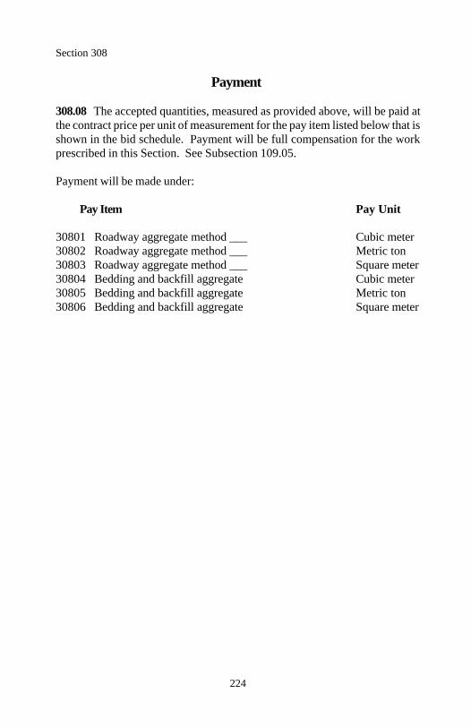
Section 308
224
Payment
308.08 The accepted quantities, measured as provided above, will be paid atthe contract price per unit of measurement for the pay item listed below that isshown in the bid schedule. Payment will be full compensation for the workprescribed in this Section. See Subsection 109.05.
Payment will be made under:
Pay Item Pay Unit
30801 Roadway aggregate method ___ Cubic meter30802 Roadway aggregate method ___ Metric ton30803 Roadway aggregate method ___ Square meter30804 Bedding and backfill aggregate Cubic meter30805 Bedding and backfill aggregate Metric ton30806 Bedding and backfill aggregate Square meter
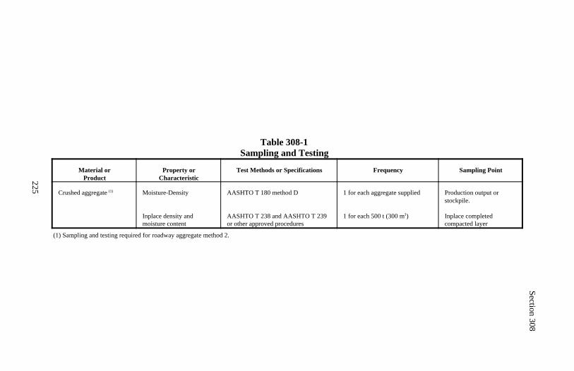
Section 308
225
Table 308-1Sampling and Testing
Material orProduct
Property orCharacteristic
Test Methods or Specifications Frequency Sampling Point
Crushed aggregate (1) Moisture-Density
Inplace density andmoisture content
AASHTO T 180 method D
AASHTO T 238 and AASHTO T 239or other approved procedures
1 for each aggregate supplied
1 for each 500 t (300 m )3
Production output orstockpile.
Inplace completedcompacted layer
(1) Sampling and testing required for roadway aggregate method 2.
226
Section 309. — EMULSIFIED ASPHALTTREATED BASE COURSE
Description
309.01 This work consists of constructing an emulsified asphalt treated basecourse on a prepared surface.
Base aggregate grading is designated as shown in Table 703-2.
Material
309.02 Conform to the following Subsections:
Base course aggregate 703.05Emulsified asphalt 702.03Water 725.01
Construction Requirements
309.03 General. Prepare the surface on which the treated aggregate basecourse is placed according to Section 204 or 303 as applicable.
After a representative quantity of aggregate is produced, submit proposedtarget values for the appropriate sieve sizes along with a representative 150-kilogram sample at least 14 days before incorporating the aggregate into thework.
Set target values within the gradation ranges shown in Table 703-2 for therequired grading.
309.04 Mixing and Spreading. Use a stationary pugmill with weighing,volumetric, or other gauging equipment capable of accurately controlling thematerial entering the mixer. Interlock the controls for the aggregate feed withthe emulsified asphalt and water controls to ensure uniform introduction ofmaterial into the mixer. Determine the optimum moisture content of the mix-ture according to AASHTO T 180 method D.
Section 309
227
Add the aggregate and water to the mixer before the emulsified asphalt. Add1 percent emulsified asphalt by mass of aggregate. Adjust the total liquidcontent (emulsified asphalt and water), so that at the time of compaction thetotal liquid content is within 2 percent of the optimum moisture content. Mixuntil all particles are uniformly coated.
Spread the mixture on the prepared surface in a uniform layer. Shape themixture to the line, grade, and cross-section. Route hauling equipment uni-formly over the full width of the surface to minimize rutting or uneven compac-tion.
309.05 Compacting. Determine the maximum density of the mixture accord-ing to AASHTO T 180 method D.
Compact the full width. Roll from the sides to the center, parallel to the center-line of the road. Along curbs, headers, walls, and all places not accessible tothe roller, compact the material with approved tampers or compactors.
Compact the mixture to at least 95 percent of maximum density. Determine theinplace density and moisture content according to AASHTO T 238 andAASHTO T 239 or other approved test procedures.
309.06 Surface Tolerance. Finish the surface according to Subsection301.06.
309.07 Maintenance. Maintain the treated aggregate course to the correctline, grade, and cross-section by blading, watering, rolling, or any combinationthereof until placement of the next course. Correct all defects according toSubsection 301.06.
309.08 Acceptance. Emulsified asphalt will be evaluated under Subsections106.03 and 702.09.
Aggregate gradation will be evaluated under Subsection 106.05. The aggregategradation upper and lower specification limits are the approved target valuesplus or minus the allowable deviations shown in Table 703-2. See Table 309-1for the acceptance quality characteristic categories and minimum sampling andtesting requirements. All other aggregate quality properties will be evaluatedunder Subsections 106.02 and 106.04.
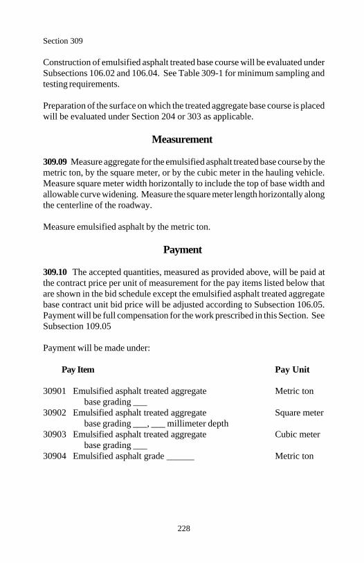
Section 309
228
Construction of emulsified asphalt treated base course will be evaluated underSubsections 106.02 and 106.04. See Table 309-1 for minimum sampling andtesting requirements.
Preparation of the surface on which the treated aggregate base course is placedwill be evaluated under Section 204 or 303 as applicable.
Measurement
309.09 Measure aggregate for the emulsified asphalt treated base course by themetric ton, by the square meter, or by the cubic meter in the hauling vehicle.Measure square meter width horizontally to include the top of base width andallowable curve widening. Measure the square meter length horizontally alongthe centerline of the roadway.
Measure emulsified asphalt by the metric ton.
Payment
309.10 The accepted quantities, measured as provided above, will be paid atthe contract price per unit of measurement for the pay items listed below thatare shown in the bid schedule except the emulsified asphalt treated aggregatebase contract unit bid price will be adjusted according to Subsection 106.05.Payment will be full compensation for the work prescribed in this Section. SeeSubsection 109.05
Payment will be made under:
Pay Item Pay Unit
30901 Emulsified asphalt treated aggregate Metric tonbase grading ___
30902 Emulsified asphalt treated aggregate Square meterbase grading ___, ___ millimeter depth
30903 Emulsified asphalt treated aggregate Cubic meterbase grading ___
30904 Emulsified asphalt grade ______ Metric ton
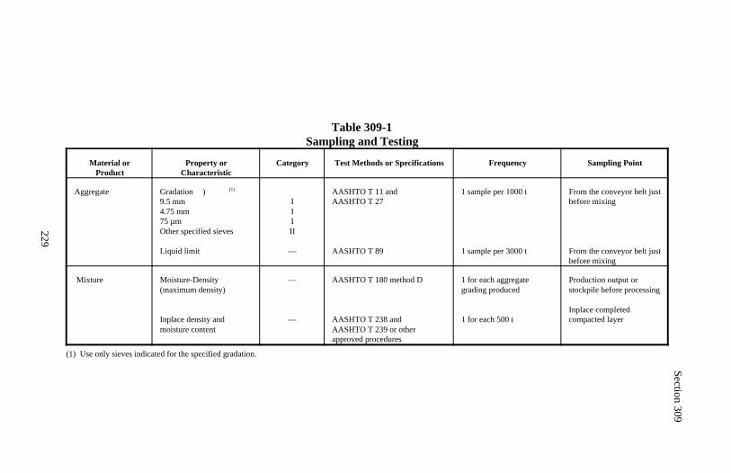
Section 309
229
Table 309-1Sampling and Testing
Material orProduct
Property orCharacteristic
Category Test Methods or Specifications Frequency Sampling Point
Aggregate Gradation ) (1)
9.5 mm4.75 mm75 µmOther specified sieves
Liquid limit
IIIII
—
AASHTO T 11 and AASHTO T 27
AASHTO T 89
1 sample per 1000 t
1 sample per 3000 t
From the conveyor belt justbefore mixing
From the conveyor belt justbefore mixing
Mixture Moisture-Density(maximum density)
Inplace density andmoisture content
—
—
AASHTO T 180 method D
AASHTO T 238 andAASHTO T 239 or otherapproved procedures
1 for each aggregategrading produced
1 for each 500 t
Production output orstockpile before processing
Inplace completedcompacted layer
(1) Use only sieves indicated for the specified gradation.

231
DIVISION 400Asphalt Pavements
andSurface Treatments
232
Section 401.) HOT ASPHALT CONCRETE PAVEMENT
Description
401.01 This work consists of constructing one or more courses of hot asphaltconcrete pavement.
Hot asphalt concrete pavement class is designated as shown in Table 401-1.Aggregate grading is designated as shown in Table 703-4. Smoothness typeis designated as shown in Table 401-7.
Superpave asphalt concrete pavement ESALs is designated as shown in Tables703-10 through 703-13. Nominal maximum size aggregate is designated asshown in Tables 703-14 through 703-16. Smoothness type is designated asshown in Table 401-7.
Asphalt cement grade is designated as shown in AASHTO M 20, AASHTO M226, or AASHTO MP 1.
Antistrip additive is designated as shown in Subsection 702.08. Where no typeis designated, use any type if needed.
Material
401.02 Conform to the following Subsections:
Aggregate (class A, B, or C mix) 703.07Aggregate (Superpave mix) 703.17Antistrip additive 702.08Asphalt cement 702.01Mineral filler 725.05
Construction Requirements
401.03 Composition of Mix (Job-Mix Formula). For all but the final sur-face course, recycled material may be used according to Section 403. Recycledmaterial may be used in the final surface course subject to approval of a Con-tractor quality control plan and submission of test data demonstrating that themix will meet the requirements of this Section.
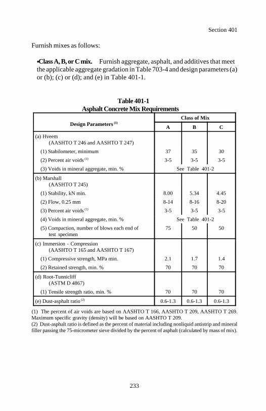
Section 401
233
Furnish mixes as follows:
Class A, B, or C mix. Furnish aggregate, asphalt, and additives that meetthe applicable aggregate gradation in Table 703-4 and design parameters (a)or (b); (c) or (d); and (e) in Table 401-1.
Table 401-1Asphalt Concrete Mix Requirements
Design Parameters (1)Class of Mix
A B C
(a) Hveem(AASHTO T 246 and AASHTO T 247)
(1) Stabilometer, minimum 37 35 30
(2) Percent air voids 3-5 3-5 3-5(1)
(3) Voids in mineral aggregate, min. % See Table 401-2
(b) Marshall(AASHTO T 245)
(1) Stability, kN min. 8.00 5.34 4.45
(2) Flow, 0.25 mm 8-14 8-16 8-20
(3) Percent air voids 3-5 3-5 3-5(1)
(4) Voids in mineral aggregate, min. % See Table 401-2
(5) Compaction, number of blows each end of 75 50 50test specimen
(c) Immersion - Compression(AASHTO T 165 and AASHTO T 167)
(1) Compressive strength, MPa min. 2.1 1.7 1.4
(2) Retained strength, min. % 70 70 70
(d) Root-Tunnicliff(ASTM D 4867)
(1) Tensile strength ratio, min. % 70 70 70
(e) Dust-asphalt ratio 0.6-1.3 0.6-1.3 0.6-1.3(2)
(1) The percent of air voids are based on AASHTO T 166, AASHTO T 209, AASHTO T 269.Maximum specific gravity (density) will be based on AASHTO T 209.(2) Dust-asphalt ratio is defined as the percent of material including nonliquid antistrip and mineralfiller passing the 75-micrometer sieve divided by the percent of asphalt (calculated by mass of mix).
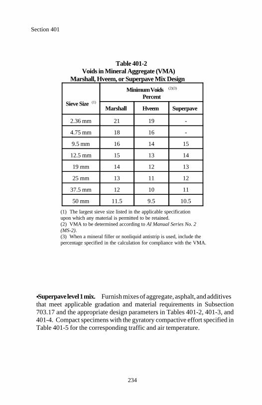
Section 401
234
Table 401-2Voids in Mineral Aggregate (VMA)
Marshall, Hveem, or Superpave Mix Design
Sieve Size (1)
Minimum Voids (2)(3)
Percent
Marshall Hveem Superpave
2.36 mm 21 19 -
4.75 mm 18 16 -
9.5 mm 16 14 15
12.5 mm 15 13 14
19 mm 14 12 13
25 mm 13 11 12
37.5 mm 12 10 11
50 mm 11.5 9.5 10.5
(1) The largest sieve size listed in the applicable specificationupon which any material is permitted to be retained.
(2) VMA to be determined according to AI Manual Series No. 2(MS-2).(3) When a mineral filler or nonliquid antistrip is used, include thepercentage specified in the calculation for compliance with the VMA.
Superpave level 1 mix. Furnish mixes of aggregate, asphalt, and additivesthat meet applicable gradation and material requirements in Subsection703.17 and the appropriate design parameters in Tables 401-2, 401-3, and401-4. Compact specimens with the gyratory compactive effort specified inTable 401-5 for the corresponding traffic and air temperature.
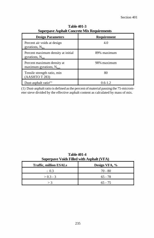
Section 401
235
Table 401-3Superpave Asphalt Concrete Mix Requirements
Design Parameters Requirement
Percent air voids at design 4.0gyrations, Ndes
Percent maximum density at initial 89% maximumgyrations, Ninit
Percent maximum density at 98% maximummaximum gyrations, Nmax
Tensile strength ratio, min 80(AASHTO T 283)
Dust-asphalt ratio 0.6-1.2(1)
(1) Dust-asphalt ratio is defined as the percent of material passing the 75-microm-eter sieve divided by the effective asphalt content as calculated by mass of mix.
Table 401-4Superpave Voids Filled with Asphalt (VFA)
Traffic, million ESALs Design VFA, %
0.3 70 - 80
> 0.3 - 3 65 - 78
> 3 65 - 75
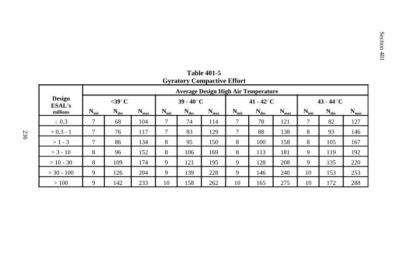
Section 401
236
Table 401-5Gyratory Compactive Effort
DesignESAL'smillions
Average Design High Air Temperature
<39 C 39 - 40 C 41 - 42 C 43 - 44 C Ninit Ndes Nmax Ninit Ndes Nmax Ninit Ndes Nmax Ninit Ndes Nmax
0.3 7 68 104 7 74 114 7 78 121 7 82 127
> 0.3 - 1 7 76 117 7 83 129 7 88 138 8 93 146
> 1 - 3 7 86 134 8 95 150 8 100 158 8 105 167
> 3 - 10 8 96 152 8 106 169 8 113 181 9 119 192
> 10 - 30 8 109 174 9 121 195 9 128 208 9 135 220
> 30 - 100 9 126 204 9 139 228 9 146 240 10 153 253
> 100 9 142 233 10 158 262 10 165 275 10 172 288
Section 401
237
Submit written job-mix formulas for approval at least 21 days before produc-tion. For each job-mix formula, submit the following:
(a) Aggregate and mineral filler.
(1) Target value for percent passing each sieve size for the aggregateblend. Designate target values within the gradation band in the specifiedgrading. Designate target values outside the restricted zone of Table 703-14, 703-15, or 703-16 for the appropriate nominal maximum size aggre-gate.
(2) Source and percentage of each aggregate stockpile to be used.
(3) Average gradation of each aggregate stockpile.
(4) Representative samples for each aggregate stockpile:
(a) 100 kilograms of each coarse aggregate(b) 70 kilograms of each intermediate and fine aggregate(c) 10 kilograms of mineral filler such as lime stone or fillerearth if proposed to improve gradation characteristics or mix perform-ance.(d) 10 kilograms of bag house fines if proposed for the mix. See Sub-section 401.04.
Aggregate samples when combined according to the Contractor's rec-ommended stockpile percentages shall be within the gradation band de-fined by the target values plus or minus the allowable deviation for eachsieve or the samples will not be considered representative.
(5) Results of aggregate quality tests.
(b) Asphalt cement.
(1) Five 4-liter samples of the asphalt cement to be used in the mix.
(2) Recent quality test results from the manufacturer for the asphalt ce-ment including a temperature-viscosity curve.
(3) Material safety data sheets.

Section 401
238
(c) Antistrip additives. When an antistrip additive is needed to meet themix requirements, furnish the following:
(1) Sample(a) 0.5 liter of liquid heat-stable antistrip additive or(b) 5 kilograms of dry antistrip additive such as lime or portlandcement
(2) Name of product(3) Manufacturer(4) Material safety data sheet
(d) Asphalt mixes. When applicable, the location of all commercial mixingplants to be used. A job-mix formula is needed for each plant.
The CO will evaluate the suitability of the material and the proposed job-mixformula. If approved, the CO will develop a target value for the asphalt cementcontent, determine the need for antistrip additive, determine the maximumspecific gravity (density) according to AASHTO T 209, and determine the dis-charge temperature range.
If a job-mix formula is rejected, submit a new job-mix formula as describedabove.
Changes to an approved job-mix formula require approval before production. Up to 14 days will be required to evaluate a change. Approved changes intarget values will not be applied retroactively for payment.
The CO will deduct all job-mix formula evaluation costs incurred as a resultof any of the following:
Contractor-requested changes to the approved job-mix formula
Contractor requests for additional job-mix formula evaluations
Additional testing necessary due to the failure of a submitted job-mix for-mula
Section 401
239
401.04 Mixing Plant. Use mixing plants conforming to AASHTO M 156supplemented as follows:
(a) All plants.
(1) Automated controls. Control the proportioning, mixing, and dis-charging of the mix automatically.
(2) Dust collector. AASHTO M 156, Requirements for All Plants, Emis-sion Controls is amended as follows:
Equip the plant with a dust collector. Dispose of the collected material.In the case of baghouse dust collectors, dispose of the collected materialor return the collected material uniformly. Use of baghouse fines in as-phalt concrete mixes requires approval unless included as part of theapproved job-mix formula.
When baghouse fines are used in batch plants or continuous mix plants,deposit the material that is returned from the baghouse at the bottom ofthe hot elevator or meter it by volume or mass into the mixing chamber.Direct return from the baghouse to the hot elevator will be permitted onlywhen the flow can be controlled at a uniform rate. In drum dryer-mixerplants, return the material to the drum at the same location as the asphalt.
(3) Aggregate storage. Store aggregate according to Section 307.
(b) Drum dryer-mixer plants.
(1) Bins. Provide a separate bin in the cold aggregate feeder for eachindividual aggregate stockpile in the mix. Use bins of sufficient size tokeep the plant in continuous operation and of proper design to preventoverflow of material from one bin to another.
(2) Stockpiling procedures. Separate aggregate into at least 2 stockpileswith different gradations. As a minimum, one stockpile shall containmostly coarse material, and one stockpile shall contain mostly fine mate-rial. Stockpile the material according to Section 307.
Section 401
240
(c) Batch and continuous mix plants.
(1) Hot aggregate bin. Provide a bin with 3 or more separate compart-ments for storage of the screened aggregate fractions to be combined forthe mix. Make the partitions between the compartments tight and ofsufficient height to prevent spillage of aggregate from one compartmentinto another.
(2) Load cells. Calibrated load cells may be used in batch plants insteadof scales.
401.05 Pavers. Use pavers that are:
(a) Self-contained, power-propelled units with adjustable vibratory screedswith full-width screw augers.
(b) Heated for the full width of the screed.
(c) Capable of spreading and finishing courses of asphalt mix in widths atleast 300 millimeters more than the width of one lane.
(d) Equipped with a receiving hopper having sufficient capacity to ensure auniform spreading operation.
(e) Equipped with automatic feed controls, which are properly adjusted tomaintain a uniform depth of material ahead of the screed.
(f) Operable at forward speeds consistent with satisfactory mix lay down.
(g) Capable of producing a finished surface of the required smoothness andtexture without segregating, tearing, shoving, or gouging the mix.
(h) Equipped with automatic screed controls with sensors capable of sensinggrade from an outside reference line, sensing the transverse slope of thescreed, and providing the automatic signals that operate the screed to main-tain grade and transverse slope.
Section 401
241
401.06 Surface Preparation. Prepare the surface according to 303.07, 413,502, or 503 as applicable. Apply an asphalt tack coat to contact surfaces ofpavements, curbs, gutters, manholes, and other structures according to Section412.
401.07 Weather Limitations. Place hot asphalt concrete pavement on a dry,unfrozen surface when the air temperature in the shade is above 2 C and risingand the temperature of the road surface in the shade conforms to Table 401-6.
Table 401-6Asphalt Concrete Mix Placement Temperature
Compacted Lift Thickness < 50 mm 50 - 75 mm > 75 mm
Road Surface Temperature C Minimum Lay-Down Temperature C(1)
< 2 (2) (2) (2)
2 - 3.9 138(2) (2)
4 - 9.9 141 135(2)
10 - 14.9 146 138 132
15 - 19.9 141 135 129
20 - 24.9 138 132 129
25 - 29.9 132 129 127
30 129 127 124
(1) In no case shall the asphalt concrete mix be heated above the temperature specified in the approved mix design. (2) Paving not allowed.
401.08 Asphalt Preparation. Uniformly heat the asphalt cement to providea continuous supply of the heated asphalt cement from storage to the mixer.Do not heat asphalt cement above 175 C.
If the job-mix formula requires a liquid heat stable antistrip additive, meter itinto the asphalt cement transfer lines at a bulk terminal or mixing plant. Injectthe additive for at least 80 percent of the transfer or mixing time to obtainuniformity.
Section 401
242
401.09 Aggregate Preparation. If nonliquid antistrip is used, adjust theaggregate moisture to at least 4 percent by mass of aggregate. Mix the antistripuniformly with the aggregate before introducing the aggregate into the dryer ordryer drum. Use calibrated weighing or metering devices to measure the a-mount of antistrip and moisture added to the aggregate.
For batch plants, heat, dry, and deliver aggregate for pugmill mixing at atemperature sufficient to produce a mix temperature within the approved range.Adjust flames used for drying and heating to prevent damage to and contamina-tion of the aggregate.
Control plant operations so the moisture content of the mix behind the paveris 0.5 percent or less according to AASHTO T 110 or FLH T 515.
401.10 Mixing. Measure the aggregate and asphalt into the mixer accordingto the approved job-mix formula. Mix until all the particles are completely anduniformly coated with asphalt according to AASHTO M 156. Maintain thedischarge temperature within the approved range.
401.11 Hauling. Use vehicles with tight, clean, and smooth metal beds forhauling asphalt concrete mixes.
Thinly coat the beds with an approved material to prevent the mix from adher-ing to the beds. Do not use petroleum derivatives or other coating materialwhich contaminate or alter the characteristics of the mix. Drain the bed beforeloading.
Equip each truck with a canvas cover or other suitable material of sufficientsize to protect the mix from the weather. When necessary to maintain tempera-ture, use insulated truck beds and securely fastened covers. Provide accessports or holes for checking temperature of asphalt mix in the truck.
401.12 Production Start-Up Procedures. Provide 7 days notice beforebeginning production of an asphalt concrete mix.
On the first day of production, produce sufficient mix to construct a 300-meterlong control strip, one-lane wide, and at the designated lift thickness. Con-struct the control strip on the project at an approved location.
Section 401
243
Construct the control strip using mix production, lay-down, and compactionprocedures intended for the entire mix. Cease production after construction ofthe control strip until the asphalt concrete mix and the control strip are evalu-ated and accepted.
(a) Asphalt content and aggregate gradation. Take at least three controlstrip asphalt concrete mix samples and evaluate according to Subsection401.17. The mix is acceptable if all test results are within specification limitsfor asphalt content and aggregate gradation.
(b) Compaction. Take nuclear density readings behind each roller pass todetermine the roller pattern necessary to achieve required density withoutdamaging the mix.
At a minimum of 4 locations within the control strip, take nuclear gaugereadings and cut and test core samples according to Subsection 401.17.Density is acceptable if all tests are above the specification limit. Furnish theCO with the nuclear gauge readings and correlations of the readings to thecore specific gravities.
Repeat the control strip process until an acceptable control strip is produced.See Subsection 106.01 for the disposition of material in unacceptable controlstrips. Accepted control strips may remain in place and will be accepted andmeasured as a part of the completed pavement. Tests used for the control stripwill not be included in the evaluation for payment according to Subsection106.05. When a control strip is accepted, full production may begin.
Use these start-up procedures when producing material from a different plantor when resuming production after a termination of production due to unsatis-factory quality according to Subsection 106.05.
401.13 Placing and Finishing. Do not use mixes produced from differentplants unless the mixes are produced according to the same job-mix formula,use material from the same sources, and are approved. Construct control stripsaccording to Subsection 401.12 for each plant from which production is in-tended.
Section 401
244
Place asphalt concrete mix at a temperature conforming to Table 401-6. Mea-sure temperature of the mix in the hauling vehicle just before dumping intospreader or measure it in the windrow immediately before pickup.
Place the mix with a paver conforming to Subsection 401.05. Control horizon-tal alignment using a reference line. Automatically control the grade and slopefrom reference lines, a ski and slope control device, or dual skis. Use skishaving a minimum length of 6 meters.
On areas where mechanical spreading and finishing is impractical, place andfinish the mix with alternate equipment to produce a uniform surface closelymatching the surface obtained when using a mechanical paver.
Offset the longitudinal joint of one layer at least 150 millimeters from the jointin the layer immediately below. Make the longitudinal joint in the top layeralong the centerline of two-lane roadways or at the lane lines of roadways withmore than two lanes.
The CO will designate the job-mix formula to be used for wedge and levelingcourses at each location. Place wedge and leveling courses in maximum 75-millimeter lifts. Complete the wedge and leveling before starting normal pav-ing operations.
401.14 Compacting. Furnish at least 3 rollers. Furnish one roller each forbreakdown, intermediate, and finish rolling. At least one roller shall bepneumatic-tired. Size the rollers to achieve the required results. Operaterollers according to the recommendation of the manufacturer.
Thoroughly and uniformly compact the asphalt surface by rolling. Do notcause undue displacement, cracking, or shoving. Continue rolling until allroller marks are eliminated and the required density is obtained. Do not rollthe mix after the surface cools below 80 C.
Monitor the compaction process with nuclear density gauges calibrated to thecontrol strip compaction test results. Compact to a pavement specific gravity(density) that is no less than 90 percent of the maximum specific gravity (den-sity) determined according to AASHTO T 209.
Section 401
245
Along forms, curbs, headers, walls, and other places not accessible to the roll-ers, compact the mix with alternate equipment to obtain the required compac-tion.
401.15 Joints, Trimming Edges, and Cleanup. Complete construction ofadjacent traffic lanes to the same elevation within 24 hours. If drop offs areleft overnight, sign the drop offs in excess of 50 millimeters with "UnevenLane" warning signs and provide a 1:3 fillet for drop offs in excess of 100millimeters.
At connections to existing pavements and previously placed lifts, make thetransverse joints vertical to the depth of the new pavement. Form transversejoints by cutting back on previous run to expose the full-depth course.
Apply an asphalt tack coat to the edge of the joint for both transverse andlongitudinal joints according to Section 412.
Place the asphalt concrete mix as continuously as possible. Do not pass rollersover the unprotected end of a freshly laid mix.
Dispose of material trimmed from the edges and any other discarded asphaltmix according to Subsection 211.03(b).
401.16 Pavement Smoothness. After final rolling, measure the smoothnessof the final surface course or the surface immediately under an open-gradedasphalt friction course.
(a) Profilograph measurements. Measure the traveled way parallel to thecenterline according to FLH T 504 after mainline paving is completed. TheCO will furnish a California type profilograph and direct and observe itsoperation. Furnish workers to operate the profilograph. Furnish the trace tothe CO.
Exclude the following areas from the profile index and profilograph bumpdetermination: bridge decks, cattle guards, traveled way lanes with hori-zontal curvature less than 150-meter radius, transverse joints with existingpavements, turning or passing lanes less than 100 meters in length, drive-ways, parking areas, and side roads less than 100 meters in length. Measureexcluded areas and type IV pavements according to (b) below.
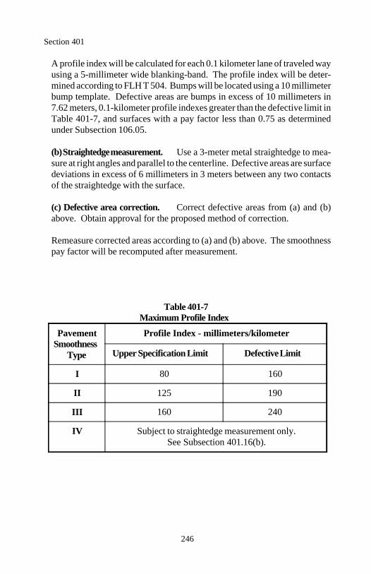
Section 401
246
A profile index will be calculated for each 0.1 kilometer lane of traveled wayusing a 5-millimeter wide blanking-band. The profile index will be deter-mined according to FLH T 504. Bumps will be located using a 10 millimeterbump template. Defective areas are bumps in excess of 10 millimeters in7.62 meters, 0.1-kilometer profile indexes greater than the defective limit inTable 401-7, and surfaces with a pay factor less than 0.75 as determinedunder Subsection 106.05.
(b) Straightedge measurement. Use a 3-meter metal straightedge to mea-sure at right angles and parallel to the centerline. Defective areas are surfacedeviations in excess of 6 millimeters in 3 meters between any two contactsof the straightedge with the surface.
(c) Defective area correction. Correct defective areas from (a) and (b)above. Obtain approval for the proposed method of correction.
Remeasure corrected areas according to (a) and (b) above. The smoothnesspay factor will be recomputed after measurement.
Table 401-7Maximum Profile Index
Pavement Profile Index - millimeters/kilometerSmoothness
Type Upper Specification Limit Defective Limit
I 80 160
II 125 190
III 160 240
IV Subject to straightedge measurement only.See Subsection 401.16(b).
Section 401
247
401.17 Acceptance. Mineral filler and antistrip additive will be evaluatedunder Subsections 106.02 and 106.03.
Asphalt will be evaluated under Subsections 106.04 and 702.09.
Construction of the hot asphalt concrete pavement course will be evaluatedunder Subsections 106.02 and 106.04.
Asphalt content, aggregate gradation, density, and pavement smoothness willbe evaluated under Subsection 106.05. Other aggregate quality properties willbe evaluated under Subsections 106.02 and 106.04. See Table 401-8 for mini-mum sampling and testing requirements.
(a) Asphalt content. The upper and lower specification limits are the ap-proved job-mix formula target value ±0.5 percent. See Table 401-8 for theacceptance quality characteristic category.
(b) Aggregate gradation. The upper and lower specification limits are theapproved job-mix formula target values plus or minus the allowable devia-tions shown in Table 703-4. See Table 401-8 for the acceptance qualitycharacteristic categories.
(c) Density. The lower specification limit is 90 percent of the maximumspecific gravity (density) determined according to AASHTO T 209 as partof the job-mix formula evaluation specified in Subsection 401.03. See Table401-8 for the acceptance quality characteristic category.
(d) Pavement smoothness. See Subsection 401.16. The evaluation will bemade after all defective areas are corrected. A sublot is a 0.1-kilometersection of the traveled way and a lot is the surface course of the entire pro-ject. The upper specification limit is shown in Table 401-7. See Table 401-8for the acceptance quality characteristic category.
Measurement
401.18 Measure hot asphalt concrete pavement, asphalt cement, mineral filler,and antistrip additive by the metric ton.
Section 401
248
Payment
401.19 The accepted quantities, measured as provided above, will be paid atthe contract price per unit of measurement for the pay items listed below thatare shown in the bid schedule except the hot asphalt concrete pavement con-tract unit bid price will be adjusted according to Subsection 106.05. Paymentwill be full compensation for the work prescribed in this Section. See Subsec-tion 109.05.
Payment for hot asphalt concrete pavement will be made at a price determinedby multiplying the contract unit bid price by the material pay factor. The mate-rial pay factor is the lowest single pay factor determined for asphalt content,specific gravity (density), or any individual sieve of the aggregate gradation.
When the bid schedule contains a pay item for hot asphalt concrete pavementtype I, II, or III pavement smoothness, a separate adjustment will be made forpavement smoothness according to the following formula:
A = 12 000(PF - 1.00)(L)
Where:
A = Adjustment to contract payment in dollars for pavement smooth-ness.
L = Total project length in lane kilometers of traveled way. Measureproject length to 3 decimal places.
PF = Pay factor for smoothness with respect to the upper specificationlimit determined according to Subsection 106.05 after completionof corrective work.
Section 401
249
Payment will be made under:
Pay Item Pay Unit
40101 Hot asphalt concrete pavement class ___, Metric tongrading ___, type ___ pavement smoothness
40102 Hot asphalt concrete pavement class ___, Metric tongrading ___, wedge and leveling course
40103 Asphalt cement grade ___ Metric ton
40104 Mineral filler Metric ton40105 Antistrip additive type ___ Metric ton 40106 Superpave asphalt concrete pavement, Metric ton
___ nominal maximum size aggregate, ___ ESALs, type ___ pavement smoothness
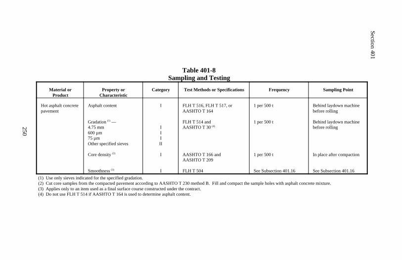
Section 401
250
Table 401-8Sampling and Testing
Material orProduct
Property orCharacteristic
Category Test Methods or Specifications Frequency Sampling Point
Hot asphalt concretepavement
Asphalt content
Gradation —(1)
4.75 mm600 µm75 µmOther specified sieves
Core density (2)
Smoothness (3)
I
IIIII
I
I
FLH T 516, FLH T 517, orAASHTO T 164
FLH T 514 and AASHTO T 30 (4)
AASHTO T 166 andAASHTO T 209
FLH T 504
1 per 500 t
1 per 500 t
1 per 500 t
See Subsection 401.16
Behind laydown machinebefore rolling
Behind laydown machinebefore rolling
In place after compaction
See Subsection 401.16(1) Use only sieves indicated for the specified gradation.(2) Cut core samples from the compacted pavement according to AASHTO T 230 method B. Fill and compact the sample holes with asphalt concrete mixture.(3) Applies only to an item used as a final surface course constructed under the contract.(4) Do not use FLH T 514 if AASHTO T 164 is used to determine asphalt content.
251
Section 402.) MINOR HOT ASPHALT CONCRETE
Description
402.01 This work consists of constructing minor hot asphalt concrete forsidewalks, paved waterways, curbs, and roadways.
Construction Requirements
402.02 Composition of Mix (Job-Mix Formula). Provide a hot asphaltconcrete mix composed of crushed stone or gravel and asphalt cement mixedin an approved plant. Use an aggregate gradation and quality and an asphaltcement grade and quality conforming to those normally used locally in theconstruction of highways by either Federal or state agencies.
Submit the strength, quality, and gradation specifications for the asphalt con-crete mix. Include copies of laboratory test reports that demonstrate the prop-erties of the aggregates, asphalt cement, additives, and mix meet Federal orstate agency specifications. Also submit the maximum specific gravity (den-sity) of the mix as determined by AASHTO T 209.
402.03 Surface Preparation. Prepare the surface according to Section 209or Subsection 303.07 as applicable.
402.04 Weather Limitations. Place asphalt concrete on a dry, unfrozensurface when the air temperature in the shade is at least 2 C and rising.
402.05 Hauling. Haul the asphalt mix using vehicles conforming to Subsec-tion 401.11.
402.06 Placing. Place the mix with a mechanical paver. For roadway paving,do not place lifts thicker than 100 millimeters. In areas where mechanicalspreading and finishing is impractical, spread and finish each course by handraking, screeding, or by other approved methods. Construct a surface that isuniform in texture and cross-section. Construct joints according to Subsection401.15.
402.07 Compacting.
(a) Roadway paving. Compact the mix to a minimum of 90 percent ofmaximum specific gravity (density). Determine density by nuclear gauge.
Section 402
252
(b) Non-roadway paving. Compact by rolling with a hand-operated rollerweighing at least 130 kilograms or with a small power roller.
Compact areas that are not accessible to rollers by other approved methods.
402.08 Pavement Smoothness. Use a 3-meter metal straightedge to measureat right angles and parallel to the centerline. Defective areas are surface devia-tions in excess of 7 millimeters in 3 meters between any two contacts of thestraightedge with the surface. Correct defective areas using approved methods.
402.09 Acceptance. Minor hot asphalt concrete mixture will be evaluatedunder Subsections 106.02 and 106.03.
Minor hot asphalt concrete construction work will be evaluated under Sub-sections 106.02 and 106.04. See Table 402-1 for minimum sampling andtesting requirements.
Measurement
402.10 Measure asphalt concrete by the metric ton.
Payment
402.11 The accepted quantities, measured as provided above, will be paid atthe contract price per unit of measurement for the pay item listed below that isshown in the bid schedule. Payment will be full compensation for the workprescribed in this Section. See Subsection 109.05.
Payment will be made under:
Pay Item Pay Unit
40201 Minor hot asphalt concrete Metric ton
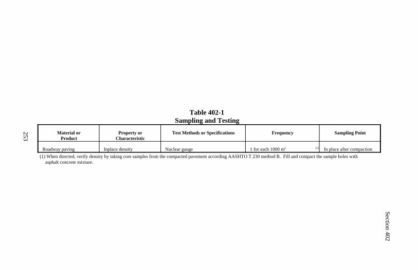
Section 402
253
Table 402-1Sampling and Testing
Material orProduct
Property orCharacteristic
Test Methods or Specifications Frequency Sampling Point
Roadway paving Inplace density Nuclear gauge (1)1 for each 1000 m 2 In place after compaction(1) When directed, verify density by taking core samples from the compacted pavement according AASHTO T 230 method B. Fill and compact the sample holes with
asphalt concrete mixture.
254
Section 403.) HOT RECYCLED ASPHALTCONCRETE PAVEMENT
Description
403.01 This work consists of constructing one or more courses of hot recycledasphalt concrete pavement using reclaimed asphalt pavement material and/orreclaimed aggregate material combined with new aggregate, asphalt cement,and/or recycling agents.
Hot recycled asphalt concrete pavement class, aggregate grading, pavementsmoothness type, asphalt cement grade, and antistrip additive type are desig-nated according to Subsection 401.01.
Material
403.02 Conform to the following Subsections:
Aggregate (new) 703.07Antistrip additive 702.08Asphalt cement 702.01Mineral filler 725.05Recycling agent 702.06
Construction Requirements
403.03 Composition of Mix (Job-Mix Formula). Prepare hot recycledasphalt concrete mixes using reclaimed aggregate material, reclaimed asphaltpavement material, new aggregate, asphalt cement, recycling agent, and addi-tives that meet the applicable aggregate gradation requirements in Table 703-4and design parameters (a) or (b); (c) or (d); and (e) in Table 401-1. Use amaximum of 50 percent reclaimed asphalt pavement material in the mix.
Submit written job-mix formulas for approval at least 30 days before produc-tion. For each job-mix formula, submit information and samples according toSubsection 401.03 and the following:
(a) Samples of the actual reclaimed asphalt pavement material, reclaimedaggregate material, and recycling agents to be incorporated in the work.
Section 403
255
Where it is necessary to obtain a sample of existing pavement, mill the exist-ing pavement to the pavement removal depth in an approved area. Replacethe removed pavement with an approved asphalt concrete mix. Do not usethe replacement material in the recycled mix.
(b) Sources of all stockpiled recyclable material.
(c) Laboratory test data on the reclaimed asphalt, new asphalt cement, andrecycling agent demonstrating the combined asphalt grade.
The job-mix formula will be evaluated and approved according to Subsection401.03.
403.04 Mixing Plant. Modify plants conforming to Subsection 401.04 ac-cording to the plant manufacturer's recommendations to process reclaimedmaterial.
(a) Batch plants. Modify batch plants to allow the introduction of reclaimedasphalt pavement material into the mix using methods that by-pass the dryer.Design the cold feed bin, conveyor system, and special bin adjacent to theweigh hopper, if used, to avoid segregation and sticking of the reclaimedasphalt pavement material.
Heat the new aggregate and/or reclaimed aggregate material to a temperaturethat will transfer sufficient heat to the reclaimed asphalt pavement materialto produce a mix of uniform temperature within the range specified in theapproved job-mix formula.
(b) Drum dryer-mixer plants. Modify drum dryer-mixer plants to preventdirect contact of the reclaimed asphalt pavement material with the burnerflame and to prevent overheating of the reclaimed asphalt pavement material.
403.05 Construction. Construct hot recycled asphalt concrete pavementaccording to Subsections 401.05 through 401.16. Dispose of reclaimed mate-rial not incorporated into the work according to Subsection 211.03.
403.06 Acceptance. Recycling agent and antistrip additive will be evaluatedunder Subsections 106.02 and 106.03.
Section 403
256
Asphalt cement will be evaluated under Subsections 106.04 and 702.09.
Construction of hot recycled asphalt concrete pavement course will be eval-uated under Subsections 106.02 and 106.04.
Asphalt content, aggregate gradation, density, and pavement smoothness willbe evaluated under Subsection 106.05. Other aggregate quality properties willbe evaluated under Subsections 106.02 and 106.04. See Table 403-1 for mini-mum sampling and testing requirements.
(a) Asphalt content. The upper and lower specification limits are the ap-proved job-mix formula target value plus or minus 0.5 multiplied by (oneplus the ratio of the reclaimed asphalt pavement material to the total mixturerounded to the nearest 0.10 percent). See Table 403-1 for acceptance qualitycharacteristic category.
Example: If 30 percent of the mixture is reclaimed asphalt pavement mate-rial, then the allowable deviation from target value for percent asphalt con-tent is 0.5(1.30) = 0.65 percent. Use plus 0.7 percent and minus 0.7 percentfrom approved job-mix formula target value for asphalt content.
(b) Aggregate gradation. The upper and lower specification limits are theapproved job-mix formula target values plus or minus the allowable devia-tions shown in Table 703-4 multiplied by (one plus the ratio of reclaimedasphalt pavement material to the total mixture). Round to the nearest percentexcept for the 75-micrometer sieve that is rounded to the nearest tenth of apercent. See Table 403-1 for acceptance quality characteristic categories.
Example: If 30 percent of the mixture is reclaimed asphalt pavement mate-rial, then the allowable deviation from target value for percent of aggregatepassing the 75-micrometer sieve is 2(1.30) or 2.6 percent. Use ±2.6 percentfrom the approved job-mix formula target value for percent passing the 75-micrometer sieve.
Section 403
257
(c) Density. The lower specification limit is 90 percent of the maximumspecific gravity (density) determined according to AASHTO T 209 as partof the job-mix formula evaluation specified in Subsection 401.03. See Table403-1 for acceptance quality characteristic category.
(d) Pavement smoothness. See Subsection 401.16. The evaluation will bemade after all defective areas are corrected. A sublot is a 0.1-kilometersection of the traveled way and a lot is the surface course of the entire pro-ject. The upper specification limit is shown in Table 401-7. See Table 403-1for acceptance quality characteristic category.
Measurement
403.07 Measure hot recycled asphalt concrete pavement, asphalt cement,mineral filler, recycling agent, and antistrip additive by the metric ton.
Measure milling under Section 413.
Payment
403.08 The accepted quantities, measured as provided above, will be paid atthe contract price per unit of measurement for the pay items listed below thatare shown in the bid schedule except the hot recycled asphalt concrete pave-ment contract unit bid price will be adjusted according to Subsection 106.05.Payment will be full compensation for the work prescribed in this Section. SeeSubsection 109.05.
Payment for hot recycled asphalt concrete pavement will be made at a pricedetermined by multiplying the contract unit bid price by the material pay factor.The material pay factor is the lowest single pay factor determined for asphaltcontent, specific gravity (density), or any individual sieve of the aggregate gra-dation
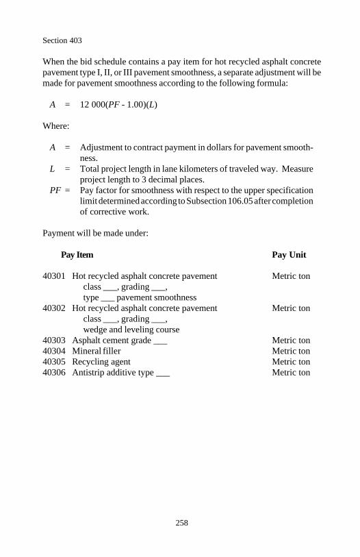
Section 403
258
When the bid schedule contains a pay item for hot recycled asphalt concretepavement type I, II, or III pavement smoothness, a separate adjustment will bemade for pavement smoothness according to the following formula:
A = 12 000(PF - 1.00)(L)
Where:
A = Adjustment to contract payment in dollars for pavement smooth-ness.
L = Total project length in lane kilometers of traveled way. Measureproject length to 3 decimal places.
PF = Pay factor for smoothness with respect to the upper specificationlimit determined according to Subsection 106.05 after completionof corrective work.
Payment will be made under:
Pay Item Pay Unit
40301 Hot recycled asphalt concrete pavement Metric tonclass ___, grading ___,type ___ pavement smoothness
40302 Hot recycled asphalt concrete pavement Metric tonclass ___, grading ___,wedge and leveling course
40303 Asphalt cement grade ___ Metric ton40304 Mineral filler Metric ton40305 Recycling agent Metric ton40306 Antistrip additive type ___ Metric ton
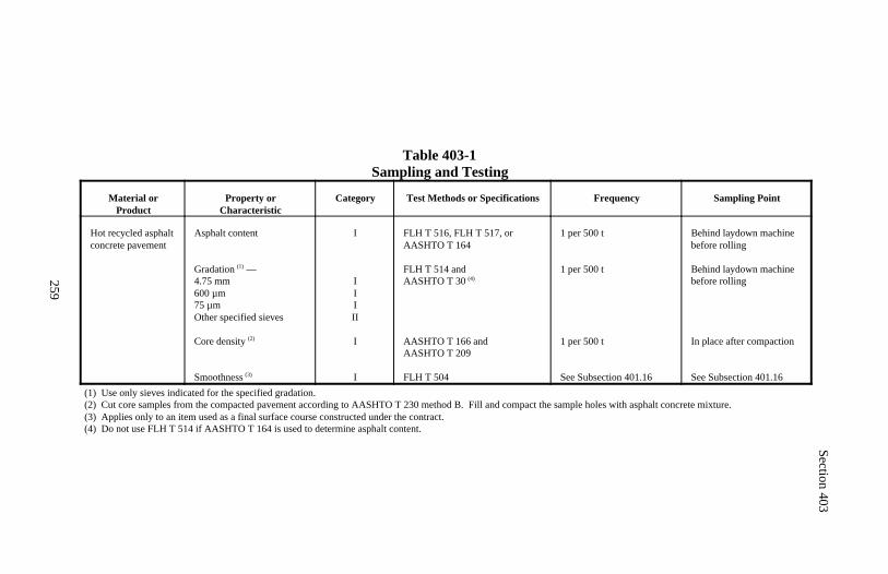
Section 403
259
Table 403-1Sampling and Testing
Material orProduct
Property orCharacteristic
Category Test Methods or Specifications Frequency Sampling Point
Hot recycled asphaltconcrete pavement
Asphalt content
Gradation —(1)
4.75 mm600 µm75 µmOther specified sieves
Core density (2)
Smoothness (3)
I
IIIII
I
I
FLH T 516, FLH T 517, orAASHTO T 164
FLH T 514 and AASHTO T 30 (4)
AASHTO T 166 andAASHTO T 209
FLH T 504
1 per 500 t
1 per 500 t
1 per 500 t
See Subsection 401.16
Behind laydown machinebefore rolling
Behind laydown machinebefore rolling
In place after compaction
See Subsection 401.16(1) Use only sieves indicated for the specified gradation.(2) Cut core samples from the compacted pavement according to AASHTO T 230 method B. Fill and compact the sample holes with asphalt concrete mixture.(3) Applies only to an item used as a final surface course constructed under the contract.(4) Do not use FLH T 514 if AASHTO T 164 is used to determine asphalt content.
260
Section 404.) OPEN-GRADED ASPHALTFRICTION COURSE
Description
404.01 This work consists of constructing an open-graded asphalt frictioncourse.
Asphalt cement grade and antistrip additive type are designated according toSubsection 401.01.
Material
404.02 Conform to the following Subsections:
Aggregate 703.08Antistrip additive 702.08Asphalt cement 702.01
Construction Requirements
404.03 Composition of Mix (Job-Mix Formula). Design an open-gradedasphalt friction course mix of aggregate, asphalt, and additives according to thedesign procedure in FHWA Technical Advisory T 5040.31, Open-GradedFriction Courses, December 1990, or by other approved method. Meet theaggregate gradation of Table 703-4 grading F. Provide an application tempera-ture range.
Submit a written job-mix formula for approval at least 21 days before produc-tion. Submit the information and samples according to Subsection 401.03.The job-mix formula will be evaluated and approved according to Subsection401.03.
404.04 Mixing Plant and Pavers. Use a mixing plant conforming to Subsec-tion 401.04. Use pavers conforming to Subsection 401.05.
404.05 Surface Preparation. Prepare the surface according to Subsection 401.06.
Section 404
261
404.06 Weather Limitations. Place open-graded asphalt friction course ona dry asphalt surface only when the air temperature in the shade is above 13 Cand the road surface temperature at least 16 C. Stop placement if eithertemperature falls below these minimums.
404.07 Preparing and Mixing Material. Prepare, mix, and control materialaccording to Subsections 401.08 through 401.10, except the temperature of theaggregate introduced into the mixer shall not exceed the optimum mixingtemperature established in the job-mix formula.
404.08 Hauling, Placing, and Finishing. Construct the open-graded asphaltfriction course according to Subsections 401.11 through 401.13, except thetemperature of the mix when placed shall be within the approved temperaturerange.
To minimize asphalt cement drainage, discharge the mix into the paver within1.5 hours of loading the truck. When surge bins are used, begin the 1.5-hourlimit at the time the mix is deposited into the surge bin.
404.09 Compacting. Roll asphalt mix parallel to centerline, commencing atthe outside edge and progressing towards the center. Use a steel-wheeled rollerin a manner that does not shove, distort, or strip the mix beneath the roller. Onsuperelevated curves, begin the rolling on the low side and progress to the highside. Limit amount of rolling to that necessary for consolidating the asphaltmix and bonding it to the underlying surface.
Provide a smooth surface according to Subsection 402.08.
404.10 Joints and Cleanup. Use butt joints for longitudinal and transversejoints. Protect the completed open-graded asphalt friction course from alltraffic until it has sufficiently hardened to resist abrasion, pickup, and ravelling.
404.11 Acceptance. Antistrip additive will be accepted under Subsections106.02 and 106.03.
Asphalt will be evaluated under Subsections 106.04 and 702.09.
Construction of the open-graded asphalt friction course will be evaluated underSubsections 106.02 and 106.04.
Section 404
262
Asphalt content and aggregate gradation will be evaluated under Subsection106.05. Other aggregate quality properties will be evaluated under Subsections106.02 and 106.04. See Table 404-1 for minimum sampling and testing re-quirements.
(a) Asphalt content. The upper and lower specification limits are the ap-proved job-mix formula target value ±0.5 percent. See Table 404-1 for theacceptance quality characteristic category.
(b) Aggregate gradation. The upper and lower specification limits are theapproved job-mix formula target values plus or minus the allowable devia-tions shown in Table 703-4 grading F. See Table 404-1 for the acceptancequality characteristic categories.
Measurement
404.12 Measure open-graded asphalt friction course, asphalt cement, andantistrip additive by the metric ton.
Payment
404.13 The accepted quantities, measured as provided above, will be paid atthe contract price per unit of measurement for the pay items listed below thatare shown in the bid schedule except the open-graded asphalt friction coursecontract unit bid price will be adjusted according to Subsection 106.05.Payment will be full compensation for the work prescribed in this Section. SeeSubsection 109.05.
Payment for open-graded asphalt friction course will be made at a price deter-mined by multiplying the contract unit bid price by the material pay factor.The material pay factor is the lowest single pay factor determined for asphaltcontent or any individual sieve of the aggregate gradation.
Payment will be made under:
Pay Item Pay Unit
40401 Open-graded asphalt friction course Metric ton40402 Asphalt cement grade ___ Metric ton40403 Antistrip additive type ___ Metric ton
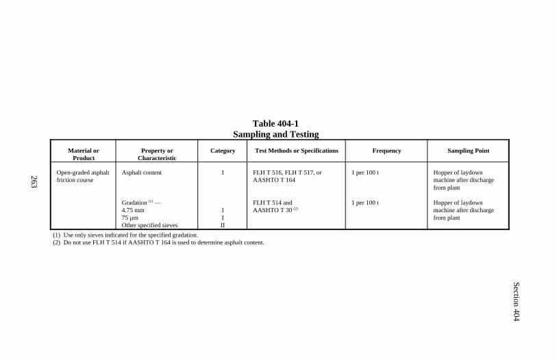
Section 404
263
Table 404-1Sampling and Testing
Material orProduct
Property orCharacteristic
Category Test Methods or Specifications Frequency Sampling Point
Open-graded asphalt friction course
Asphalt content
Gradation —(1)
4.75 mm75 µmOther specified sieves
I
IIII
FLH T 516, FLH T 517, orAASHTO T 164
FLH T 514 and AASHTO T 30 (2)
1 per 100 t
1 per 100 t
Hopper of laydownmachine after dischargefrom plant
Hopper of laydownmachine after dischargefrom plant
(1) Use only sieves indicated for the specified gradation.(2) Do not use FLH T 514 if AASHTO T 164 is used to determine asphalt content.
264
Section 405.) HOT ASPHALT TREATED BASE COURSE
Description
405.01 This work consists of constructing one or more courses of hot asphalttreated base.
Hot asphalt treated base course aggregate grading is designated as shown inTable 703-2.
Asphalt cement grade and antistrip additive type are designated according toSubsection 401.01.
Material
405.02 Conform to the following Subsections:
Aggregate 703.05Antistrip additive 702.08Asphalt cement 702.01Mineral filler 725.05
Construction Requirements
405.03 Composition of Mix (Job-Mix Formula). Furnish a mixture of ag-gregate, asphalt cement, and additives that meets the applicable aggregategradation in Table 703-2 and the class C design parameters (a)(1), (b)(1), or(c)(1); and (c)(2) or (d)(1) in Table 401-1.
Submit a written job-mix formula for approval at least 21 days before produc-tion. Submit the information and samples according to Subsection 401.-03. The job-mix formula will be evaluated and approved according to Subsec-tion 401.03.
405.04 Mixing Plant. Use a plant conforming to Subsection 401.04, except:
(a) For pugmill type mixers, plant screens are not required, except to removeoversize material.
(b) Bins do not need to be divided.
(c) For drum dryer mixers, two separate stockpiles are not required.
Section 405
265
405.05 Construction. Prepare the surface according to Subsection 303.07.Construct the base course according to Subsections 401.05 through 401.15.Provide a smooth surface according to Subsection 402.08.
405.06 Acceptance. Mineral filler and antistrip additive will be evaluatedunder Subsections 106.02 and 106.03.
Asphalt will be evaluated under Subsections 106.04 and 702.09.
Construction of the hot asphalt treated base course will be evaluated underSubsections 106.02 and 106.04.
Asphalt content, aggregate gradation, and density will be evaluated underSubsection 106.05. Other aggregate quality properties will be evaluated underSubsections 106.02 and 106.04. See Table 405-1 for minimum sampling andtesting requirements.
(a) Asphalt content. The upper and lower specification limits are the ap-proved job-mix formula target value ±0.5 percent. See Table 405-1 for theacceptance quality characteristic category.
(b) Aggregate gradation. The upper and lower specification limits are theapproved job-mix formula target values plus or minus the allowable devia-tions shown in Table 703-2. See Table 405-1 for the acceptance qualitycharacteristic categories.
(c) Density. The lower specification limit is 90 percent of the maximumspecific gravity (density) determined according to AASHTO T 209 as partof the job-mix formula evaluation specified in Subsection 401.03. See Table405-1 for the acceptance quality characteristic category.
Measurement
405.07 Measure hot asphalt treated base course, asphalt cement, mineral filler,and antistrip additive by the metric ton.
Section 405
266
Payment
405.08 The accepted quantities, measured as provided above, will be paid atthe contract price per unit of measurement for the pay items listed below thatare shown in the bid schedule except the hot asphalt treated base course con-tract unit bid price will be adjusted according to Subsection 106.05. Paymentwill be full compensation for the work prescribed in this Section. See Subsec-tion 109.05.
Payment for hot asphalt treated base course will be made at a price determinedby multiplying the contract unit bid price by the material pay factor. The paymaterial factor is the lowest single pay factor determined for asphalt content,specific gravity (density), or any individual sieve of the aggregate gradation.
Payment will be made under:
Pay Item Pay Unit
40501 Hot asphalt treated base course grading ___ Metric ton40502 Asphalt cement grade ___ Metric ton40503 Mineral filler Metric ton40504 Antistrip additive type ___ Metric ton
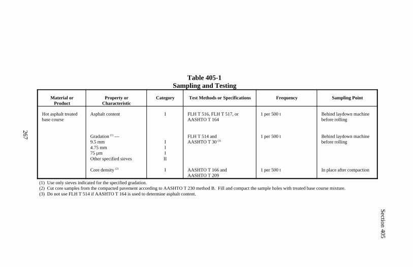
Section 405
267
Table 405-1Sampling and Testing
Material orProduct
Property orCharacteristic
Category Test Methods or Specifications Frequency Sampling Point
Hot asphalt treatedbase course
Asphalt content
Gradation —(1)
9.5 mm4.75 mm75 µmOther specified sieves
Core density (2)
I
IIIII
I
FLH T 516, FLH T 517, orAASHTO T 164
FLH T 514 and AASHTO T 30 (3)
AASHTO T 166 andAASHTO T 209
1 per 500 t
1 per 500 t
1 per 500 t
Behind laydown machinebefore rolling
Behind laydown machinebefore rolling
In place after compaction
(1) Use only sieves indicated for the specified gradation.(2) Cut core samples from the compacted pavement according to AASHTO T 230 method B. Fill and compact the sample holes with treated base course mixture.(3) Do not use FLH T 514 if AASHTO T 164 is used to determine asphalt content.
268
Section 406.) DENSE-GRADEDEMULSIFIED ASPHALT PAVEMENT
Description
406.01 This work consists of constructing one or more courses of dense-grad-ed emulsified asphalt mix.
Dense-graded emulsified asphalt pavement aggregate grading is designated asshown in Table 703-5.
Emulsified asphalt grade is designated as shown in AASHTO M 140 orAASHTO M 208.
Material
406.02 Conform to the following Subsections:
Aggregate 703.09Blotter 703.13Emulsified asphalt 702.03Mineral filler 725.05Water 725.01
Construction Requirements
406.03 Composition of Mix (Job-Mix Formula). Furnish a mixture ofaggregate, emulsified asphalt, additives, and/or water that meets the applicableaggregate gradation in Table 703-5 and the design parameters (a); and (b) or(c) in Table 406-1.
Submit a written job-mix formula for approval at least 21 days before produc-tion. Submit the following:
(a) Aggregate.
(1) Target value for each sieve size for the aggregate blend.(2) Percentage of each aggregate stockpile to be used.(3) Average gradation of each aggregate stockpile.(4) Proportional samples representing each aggregate stockpile, about300 kilograms total.
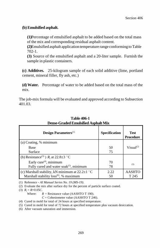
Section 406
269
(b) Emulsified asphalt.
(1) Percentage of emulsified asphalt to be added based on the total massof the mix and corresponding residual asphalt content.(2) Emulsified asphalt application temperature range conforming to Table702-1.(3) Source of the emulsified asphalt and a 20-liter sample. Furnish thesample in plastic containers.
(c) Additives. 25-kilogram sample of each solid additive (lime, portlandcement, mineral filler, fly ash, etc.)
(d) Water. Percentage of water to be added based on the total mass of themix.
The job-mix formula will be evaluated and approved according to Subsection401.03.
Table 406-1Dense-Graded Emulsified Asphalt Mix
Design Parameters Specification Test(1)
Procedure (a) Coating, % minimum
Base 50 Visual Surface 75
(2)
(b) Resistance ) R at 22.8±3 C(3)t
Early cure , minimum 70(4)
Fully cured and water soak , minimum 78(5) (3)
(c) Marshall stability, kN minimum at 22.2±1 C 2.22 AASHTO Marshall stability loss , % maximum 50 T 245(6)
(1) Reference - AI Manual Series No. 19 (MS-19).(2) Evaluate the mix after surface dry for the percent of particle surface coated.(3) R = R+0.05C.t
Where: R = Resistance value (AASHTO T 190).C = Cohesiometer value (AASHTO T 246).
(4) Cured in mold for total of 24 hours at specified temperature.(5) Cured in mold for total of 72 hours at specified temperature plus vacuum desiccation.(6) After vacuum saturation and immersion.
Section 406
270
406.04 Mixing Plant. Use a pugmill or drum dryer-mixer plant equipped withweighing or volumetric gauging equipment capable of providing accuratecontrol of the material entering the mixer.
Interlock the aggregate feed controls with the emulsified asphalt, additive, andwater controls to ensure uniform introduction of the material into the mixer.Use equipment conforming to AASHTO M 156 for handling emulsified as-phalt. Use positive displacement pumps to control the flow of emulsifiedasphalt. Provide dry storage facilities for additives.
406.05 Surface Preparation. Prepare the surface according to Subsection401.06.
406.06 Weather Limitations. Place the emulsified asphalt pavement on adry, unfrozen surface only when the air temperature in the shade is above 10C and the pavement surface temperature is above 4 C.
Do not place emulsified asphalt mix when fog, showers, rain, frost, or tempera-tures below 2 C are anticipated within 24 hours following the placement ofthe mix.
406.07 Mixing, Hauling, Placing, Finishing, and Compacting. Constructthe dense-graded emulsified asphalt pavement according to Subsections 401.10through 401.15, except:
(a) Add the following to Subsection 401.10:
(1) Where combining with the emulsified asphalt, maintain the aggregatetemperature between 16 and 80 C.
(2) Maintain emulsified asphalt temperature within the approved range.
(3) Combine and dry mix the aggregate according to the approved job-mix formula for a period sufficient to provide a uniform batch gradation.Add additives and water before the emulsified asphalt. Mix the materialuntil particles are uniformly coated and a mixture of uniform color andeven distribution of coarse and fine particles is obtained.
(b) Delete the reference to Table 401-6 in Subsection 401.13.
Section 406
271
(c) Add the following to Subsection 401.14:
Compact when the fluid content (emulsified asphalt and water) is within 2percent of the optimum fluid content determined by the CO and the residualasphalt content is within 0.75 percent of the percent in the job-mix formula.Use a steel-wheeled roller having a minimum mass of 8 metric tons forbreakdown rolling and a pneumatic-tired roller with maximum tire pressureof 275 kilopascals for intermediate rolling.
Provide a smooth surface according to Subsection 402.08. Correct defectiveareas by removing or adding material and recompacting.
Where public traffic is permitted on a compacted mix, spread blotter on areaswhere tracking or pickup of material occurs.
Allow the surface to cure for not less than 10 days before covering with thenext course or treatment. During this period, maintain the surface and keep itfree of corrugations. Patch all holes that develop with approved material.Remove all excess blotter, dirt, or other objectionable substances before plac-ing the following course or treatment.
406.08 Acceptance. Mineral filler and blotter will be evaluated under Subsec-tions 106.02 and 106.03.
Emulsified asphalt will be evaluated under Subsections 106.04 and 702.09.
Construction of the dense-graded emulsified asphalt pavement course will beevaluated under Subsections 106.02 and 106.04.
Residual asphalt content and aggregate gradation will be evaluated under Sub-section 106.05. Density and other aggregate quality properties will be evalu-ated under Subsections 106.02 and 106.04. See Table 406-2 for minimumsampling and testing requirements.
(a) Residual asphalt content. The upper and lower specification limits arethe approved job-mix formula target value ±0.75 percent. See Table 406-2for the acceptance quality characteristic category.
Section 406
272
(b) Aggregate gradation. The upper and lower specification limits are theapproved job-mix formula target values plus or minus the allowable devia-tions shown in Table 703-5. See Table 406-2 for the acceptance qualitycharacteristic categories.
Measurement
406.09 Measure dense-graded emulsified asphalt pavement, emulsified as-phalt, and mineral filler by the metric ton. Do not adjust the scale masses ofthe mix for the emulsified asphalt, moisture content, or additives.
Payment
406.10 The accepted quantities, measured as provided above, will be paid atthe contract price per unit of measurement for the pay items listed below thatare shown in the bid schedule except the dense-graded emulsified asphaltpavement contract unit bid price will be adjusted according to Subsection106.05. Payment will be full compensation for the work prescribed in this Sec-tion. See Subsection 109.05.
Payment for dense-graded emulsified asphalt pavement will be made at a pricedetermined by multiplying the contract unit bid price by the material pay factor.The material pay factor is the lowest single pay factor determined for residualasphalt content or any individual sieve of the aggregate gradation.
Payment will be made under:
Pay Item Pay Unit
40601 Dense-graded emulsified asphalt pavement Metric tongrading ___
40602 Emulsified asphalt grade ___ Metric ton40603 Mineral filler Metric ton
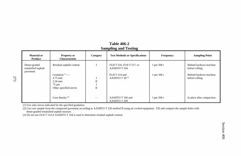
Section 406
273
Table 406-2Sampling and Testing
Material orProduct
Property orCharacteristic
Category Test Methods or Specifications Frequency Sampling Point
Dense-gradedemulsified asphaltpavement
Residual asphalt content
Gradation —(1)
4.75 mm2.36 mm75 µmOther specified sieves
Core density (2)
I
IIIIII
—
FLH T 516, FLH T 517, orAASHTO T 164
FLH T 514 and AASHTO T 30 (3)
AASHTO T 166 andAASHTO T 209
1 per 500 t
1 per 500 t
1 per 500 t
Behind laydown machinebefore rolling
Behind laydown machine before rolling
In place after compaction
(1) Use only sieves indicated for the specified gradation.(2) Cut core sample from the compacted pavement according to AASHTO T 230 method B using air-cooled equipment. Fill and compact the sample holes with dense-graded emulsified asphalt mixture.(3) Do not use FLH T 514 if AASHTO T 164 is used to determine residual asphalt content.
274
Section 407.) OPEN-GRADEDEMULSIFIED ASPHALT PAVEMENT
Description
407.01 This work consists of constructing one or more courses of open-gradedemulsified asphalt.
Open-graded emulsified asphalt pavement aggregate grading is designated asshown in Table 703-6.
Emulsified asphalt grade is designated as shown in AASHTO M 140 orAASHTO M 208.
Material
407.02 Conform to the following Subsections:
Aggregate 703.09Choker aggregate 703.12Emulsified asphalt 702.03Water 725.01
Construction Requirements
407.03 Composition of Mix (Job-Mix Formula). Furnish a mixture of ag-gregate, emulsified asphalt, additives, and/or water that meets the aggregategradation in Table 703-6 and design parameters in Table 407-1.
Submit a written job-mix formula for approval at least 21 days before produc-tion. Submit according to Subsection 406.03, except, if applicable, specify thepercent of water to be added. Use a maximum moisture content approximatelythe same as the saturated surface dry condition of the aggregate as determinedby AASHTO T 85.
The job-mix formula will be evaluated and approved according to Subsection401.03.
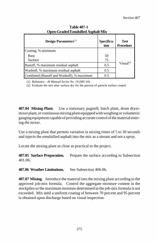
Section 407
275
Table 407-1Open-Graded Emulsified Asphalt Mix
Design Parameters Specifica- Test(1)
tion ProcedureCoating, % minimum
Visual(2)
Base 50Surface 75
Runoff, % maximum residual asphalt 0.5Washoff, % maximum residual asphalt 0.5Combined (Runoff and Washoff), % maximum 0.5
(1) Reference - AI Manual Series No. 19 (MS-19).(2) Evaluate the mix after surface dry for the percent of particle surface coated.
407.04 Mixing Plant. Use a stationary pugmill, batch plant, drum dryer-mixer plant, or continuous mixing plant equipped with weighing or volumetricgauging equipment capable of providing accurate control of the material enter-ing the mixer.
Use a mixing plant that permits variation in mixing times of 5 to 30 secondsand injects the emulsified asphalt into the mix as a stream and not a spray.
Locate the mixing plant as close as practical to the project.
407.05 Surface Preparation. Prepare the surface according to Subsection401.06.
407.06 Weather Limitations. See Subsection 406.06.
407.07 Mixing. Introduce the material into the mixing plant according to theapproved job-mix formula. Control the aggregate moisture content in thestockpiles so the maximum moisture determined in the job-mix formula is notexceeded. Mix until a uniform coating of between 70 percent and 95 percentis obtained upon discharge based on visual inspection.
Section 407
276
407.08 Hauling, Spreading, and Finishing. Use hauling vehicles conform-ing to Subsection 401.11. Begin placement at the point farthest from the mix-ing plant and progress toward the plant. Minimize hauling over material al-ready placed and do not drive on the material until it is compacted. Cleanupasphalt material dripping from the hauling vehicles onto previously constructedpavement on a daily basis.
Do not use mixes produced from different plants unless the mixes are producedaccording to the same job-mix formula, use the same material from the samesources, and the procedure is approved.
Place the mix using pavers conforming to Subsection 401.05. Spread, strikeoff, and finish the mix to the grade and elevation needed to provide the com-pacted thickness. Offset and locate longitudinal joints according to Subsection401.13.
Clean the paver immediately after use. Clean only in locations where asphaltmaterial will not be discharged into a borrow pit, ditch, gutter, or stream, oronto a completed pavement.
407.09 Compaction. Compact when the fluid content (emulsified asphalt andwater) is within ±2 percent of the optimum fluid content determined by the COand the residual asphalt content is within ±0.5 percent of the approved job-mixformula percent. Make up any deficiencies in residual asphalt content throughthe application of a flush coat.
Furnish the number, mass, and type of rollers to obtain density without unduedisplacement, cracking, or shoving. Move the rollers at a uniform speed notto exceed 5 kilometers per hour, with the drive wheels nearest the paver.
Immediately correct undue displacement resulting from the reversing of thedirection of a roller, or other causes, by the use of rakes and fresh mix. Do notdisplace the line and grade of the edges.
Begin rolling at the sides and proceed parallel to the road centerline. Overlapeach trip one-half the roller width, gradually progressing to the crown of theroad. On superelevated curves, begin the rolling at the low side and progressto the high side by overlapping passes parallel to the centerline.
Section 407
277
Make a minimum of 3 complete roller passes using a nonvibratory 2 steel-wheeled roller having a minimum mass of 8 metric tons for breakdown rolling.
Immediately after breakdown rolling, place choker aggregate using a spreaderdesigned for the controlled spreading of sand. Spread the choker aggregate atthe rate of 1.7 to 3.2 kilograms per square meter.
Make a minimum of 2 complete roller passes using a self-propelled pneumatic-tired roller with a tire pressure of approximately 275 kilopascals for intermedi-ate rolling. Obtain a uniform textured surface with a minimum of voids.
Use a nonvibratory 2 steel-wheeled roller for finish rolling. Continue finishrolling until all roller marks are eliminated.
Provide a smooth surface according to Subsection 402.08. Correct defectiveareas by removing or adding material and recompacting.
Along forms, curbs, headers, walls, and other places not accessible to the roll-ers, thoroughly compact the mix with mechanical hand tampers. Constructjoints, trim edges, and cleanup according to Subsection 401.15.
407.10 Flush Coat. Allow the surface to cure for a minimum of 2 days.Maintain the surface and keep it free of corrugations. Patch any holes thatdevelop with approved material. Remove all excess choker aggregate, dirt, orother objectionable substances.
If the final surface will be used for the driving surface, apply a flush coat ofemulsified asphalt using an asphalt distributor according to Subsection 409.04.Use the same emulsified asphalt type and grade as used for the mix. Addwater to the emulsified asphalt and thoroughly mix to produce a blend contain-ing approximately 50 percent emulsified asphalt and 50 percent added water.
When introducing water into a CMS-2, CMS-2s, or CMS-2h emulsified as-phalt, heating of the water may be necessary. Spread the blend at the rate of0.2 to 0.7 liter per square meter. The CO will determine the total number ofapplications.
Section 407
278
407.11 Surface Treatment. Allow the surface to cure for a minimum of 10days according to Subsection 407.10. When required by the contract, place asurface treatment according to Section 409.
407.12 Acceptance. Choker aggregate will be evaluated under Subsections106.02 and 106.03.
Emulsified asphalt will be evaluated under Subsections 106.04 and 702.09.
Construction of the open-graded emulsified asphalt pavement course will beevaluated under Subsections 106.02 and 106.04.
Residual asphalt content and aggregate gradation will be evaluated under Sub-section 106.05. Other aggregate quality properties will be evaluated underSubsections 106.02 and 106.04. See Table 407-2 for minimum sampling andtesting requirements.
(a) Residual asphalt content. The upper and lower specification limits arethe approved job-mix formula target value ±0.5 percent. See Table 407-2 forthe acceptance quality characteristic category.
(b) Aggregate gradation. The upper and lower specification limits are theapproved job-mix formula target values plus or minus the allowable devia-tions shown in Table 703-6. See Table 407-2 for the acceptance qualitycharacteristic categories.
Flush coat will be evaluated under Section 409.
Measurement
407.13 Measure open-graded emulsified asphalt pavement, emulsified asphaltfor pavement and flush coat, and choker aggregate by the metric ton. Do notadjust the scale masses of the mix for the emulsified asphalt or moisture con-tent.
Measure surface treatment under Section 409.
Section 407
279
Payment
407.14 The accepted quantities, measured as provided above, will be paid atthe contract price per unit of measurement for the pay items listed below thatare shown in the bid schedule except the open-graded emulsified asphalt pave-ment contract unit bid price will be adjusted according to Subsection 106.05.Payment will be full compensation for the work prescribed in this Section. SeeSubsection 109.05.
Payment for open-graded emulsified asphalt pavement will be made at a pricedetermined by multiplying the contract unit bid price by the material pay factor.The material pay factor is the lowest single pay factor determined for residueasphalt content or any individual sieve of the aggregate gradation.
Payment will be made under:
Pay Item Pay Unit
40701 Open-graded emulsified asphalt Metric tonpavement grading ___
40702 Emulsified asphalt grade ___ Metric ton40703 Choker aggregate Metric ton
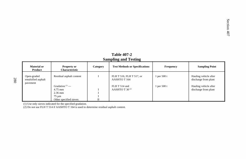
Section 407
280
Table 407-2Sampling and Testing
Material orProduct
Property orCharacteristic
Category Test Methods or Specifications Frequency Sampling Point
Open-gradedemulsified asphaltpavement
Residual asphalt content
Gradation —(1)
4.75 mm2.36 mm75 µmOther specified sieves
I
IIIII
FLH T 516, FLH T 517, orAASHTO T 164
FLH T 514 and AASHTO T 30 (2)
1 per 500 t
1 per 500 t
Hauling vehicle afterdischarge from plant
Hauling vehicle afterdischarge from plant
(1) Use only sieves indicated for the specified gradation.(2) Do not use FLH T 514 if AASHTO T 164 is used to determine residual asphalt content.
281
Section 408.) COLD RECYCLEDASPHALT BASE COURSE
Description
408.01 This work consists of constructing one or more courses of cold recy-cled asphalt base using reclaimed asphalt pavement material and/or reclaimedaggregate material combined with new aggregates, water, emulsified asphalt,recycling agents, and/or lime.
Cold recycled asphalt base course aggregate grading is designated as shown inTable 703-5.
Emulsified asphalt grade is designated as shown in AASHTO M 140 orAASHTO M 208.
Material
408.02 Conform to the following Subsections:
Aggregate (new) 703.06Emulsified asphalt 702.03Lime 725.03Recycling agent 702.06Water 725.01
Construction Requirements
408.03 Composition of Mix (Job-Mix Formula). Furnish a mixture of re-claimed aggregate material, reclaimed asphalt pavement material, new aggre-gate, water, emulsified asphalt, recycling agent, and/or lime that meets theapplicable aggregate gradation in Table 703-5 and the design parameters (a);and (b) or (c) in Table 406-1.
Submit a written job-mix formula for approval at least 21 days before produc-tion. Submit the following:
(a) Aggregate. Sources of and proportional samples representing the re-claimed asphalt pavement material, reclaimed aggregate material, and newaggregate, about 300 kilograms total. Obtain samples of existing pavementaccording to Subsection 403.03(a).
Section 408
282
(b) Emulsified asphalt.
(1) Percentage of emulsified asphalt and/or recycling agent to be addedbased on the total mass of the mixture or the application rate if sprayapplication is used.
(2) Source of and 20-liter sample of the emulsified asphalt and/or recy-cling agent to be used in the mixture. Furnish the samples in plastic con-tainers.
(c) Water. Percentage of water to be added based on the total mass of themixture.
(d) Lime. Percentage of lime added based on total mass of the mixture.
The job-mix formula will be evaluated and approved according to Subsection401.03.
408.04 Surface Preparation. For inplace mixing, clear, grub, and dispose ofall vegetation and debris within 300 millimeters of the pavement to be recy-cled. Perform the work according to Section 201. Prepare the surface accord-ing to Subsection 303.07.
408.05 Weather Limitations. See Subsection 406.06.
408.06 Mixing. Use rotary mixers, cold-milling machines, travel plants,stationary mixing plants, or other approved equipment for producing the com-pleted base course mixture.
For inplace mixing, use self-propelled equipment capable of scarifying, crush-ing, mixing, weighing, and placing the mixture. Use equipment with meterscapable of registering the rate of addition of the emulsified asphalt, recyclingagent, or water. Adjust the travel speed and/or number of passes to obtain athorough and uniform mixture.
For central plant mixing, use suitable equipment for scarifying and crushing theexisting pavement. Use acceptable continuous flow or batch-type mixer equip-ped with batching or metering devices designed to measure the specified quan-tities of the respective material.
Section 408
283
The final emulsified asphalt, recycling agent, and/or lime content will be estab-lished by the CO after evaluation of field results.
408.07 Spreading, Finishing, and Compacting. Spread, finish, and compactthe mixture according to Subsection 406.07.
After the recycled mixture has been compacted, do not permit any traffic on thecompleted cold recycled asphalt base for at least 2 hours. Allow the pavementto cure according to Subsection 406.07 before placing the next course or seal-ing the surface with a fog seal according to Section 409.
408.08 Acceptance. Recycling agent and lime will be evaluated under Sub-sections 106.02 and 106.03.
Emulsified asphalt will be evaluated under Subsections 106.04 and 702.09.
Aggregate (new) will be evaluated under Subsections 106.02 and 106.04. SeeTable 408-1 for minimum sampling and testing requirements.
Construction of the cold recycled asphalt base course will be evaluated underSubsections 106.02 and 106.04. Cold recycled asphalt base density will beevaluated under Subsections 106.02 and 106.04. See Table 408-1 for mini-mum sampling and testing requirements.
Measurement
408.09 Measure cold recycled asphalt base course by the metric ton or by thesquare meter. When measurement is by the metric ton, do not deduct for theemulsified asphalt, recycling agent, water, and/or lime contained in the mixture.Measure square meter width horizontally to include the top of base width andallowable curve widening. Measure the square meter length horizontally alongthe centerline of the roadway.
Measure emulsified asphalt, lime, and recycling agent by the metric ton.
Measure fog seal under Section 409.
Section 408
284
Payment
408.10 The accepted quantities, measured as provided above, will be paid atthe contract price per unit of measurement for the pay items listed below thatare shown in the bid schedule. Payment will be full compensation for the workprescribed in this Section. See Subsection 109.05.
Payment will be made under:
Pay Item Pay Unit
40801 Cold recycled asphalt base course grading ___ Metric ton40802 Cold recycled asphalt base course grading ___, Square meter
___ millimeter depth40803 Emulsified asphalt grade ___ Metric ton40804 Recycling agent Metric ton40805 Lime Metric ton
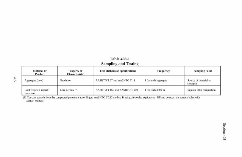
Section 408
285
Table 408-1Sampling and Testing
Material orProduct
Property orCharacteristic
Test Methods or Specifications Frequency Sampling Point
Aggregate (new) Gradation AASHTO T 27 and AASHTO T 11 1 for each aggregate Source of material orstockpile
Cold recycled asphaltpavement
Core density (1) AASHTO T 166 and AASHTO T 209 1 for each 3500 m 2In place after compaction
(1) Cut core sample from the compacted pavement according to AASHTO T 230 method B using air-cooled equipment. Fill and compact the sample holes with asphalt mixture.
286
Section 409.) ASPHALT SURFACE TREATMENT
Description
409.01 This work consists of constructing a single or multiple asphalt surfacetreatment course. A fog seal is an asphalt surface treatment without aggregate.
The grade of asphalt is designated as shown in AASHTO M 20 or AASHTOM 226 for asphalt cement, AASHTO M 140 or AASHTO M 208 for emulsi-fied asphalt, and AASHTO M 81 or AASHTO M 82 for cut-back asphalt.
Surface treatment aggregate designation is designated as shown in Tables 409-1, 409-2, and 409-3.
Material
409.02 Conform to the following Subsections:
Aggregate 703.10Asphalt cement 702.01Blotter 703.13Cut-back asphalt 702.02Emulsified asphalt 702.03
Construction Requirements
409.03 Composition of Mix. For surface treatments, submit the followinginformation and samples for approval at least 21 days before production:
(a) Aggregate samples. 35 kilograms from each stockpile produced and thegradation range represented by each.
(b) Aggregate gradation target values. The proposed percentage of eachstockpile to be used and the proposed target value for each sieve size.
(c) Asphalt samples. 2 liters of asphalt from the same source and of the typeto be used for the surface treatment.
Section 409
287
(d) Asphalt temperature. Apply asphalt at temperatures according to Table702-1.
409.04 Equipment. Furnish equipment as follows:
(a) Asphalt distributor.
(1) Capable of heating asphalt evenly.(2) Adjustable full circulation spray bar to 4.6-meter width.(3) Positive controls including tachometer, pressure gauge, volume mea-suring device, or calibrated tank to uniformly deposit asphalt over the fullwidth within 0.08 liter per square meter of the required rate.(4) Thermometer for measuring the asphalt temperature in the tank.
(b) Rotary power broom.
(c) Pneumatic-tire rollers.
(1) Minimum compacting width ) 1.5 meters.(2) Minimum ground contact pressure ) 550 kilopascals.
(d) Aggregate spreader.
(1) Self-propelled.(2) Minimum of 4 pneumatic tires on 2 axles.(3) Positive controls to uniformly deposit the aggregate over the full widthof asphalt within 10 percent by mass of the required rates.
(e) Other equipment. Other equipment of proven performance may be usedin addition to or in lieu of the specified equipment when approved.
409.05 Surface Preparation. Prepare surface according to Subsection303.07.
409.06 Weather Limitations. Place asphalt seal coats when the air tempera-ture in the shade and the pavement surface temperature are at least 16 C andrising and when the weather is not foggy or rainy.
Section 409
288
409.07 Production Start-Up Procedures for Surface Treatment. Provide7 days advance notice before constructing all asphalt surface treatments con-taining aggregate. Also use these start-up procedures when resuming produc-tion after termination due to nonconforming work.
On the first day of production, construct a 150-meter control strip that is one-lane wide. Locate the control strip on the project as designated.
Construct the control strip using material, lay-down, and compaction proce-dures intended for the remainder of the surface treatment. Cease productionafter construction of the control strip until the material and the control strip areevaluated and accepted.
Acceptable control strips may remain in place and will be accepted as a part ofthe completed surface treatment.
Repeat control strip process until an acceptable control strip is produced.
409.08 Asphalt Application. Calibrate the asphalt distributor spray barheight, nozzle angle, and pump pressure and check longitudinal and transversespread rates weekly according to ASTM D 2995.
Protect the surfaces of nearby objects to prevent spattering or marring. Spreadbuilding paper on the surface for a sufficient distance from the beginning andend of each application so the flow through the distributor nozzles may bestarted and stopped on the paper.
The CO will approve the exact application rate, temperature, and area to betreated before application and may make adjustments for variations in fieldconditions. Apply the asphalt uniformly with an asphalt distributor. Movedistributor forward at the proper application speed at the time the spray bar isopened. Use care not to apply excess asphalt at the junction of spreads.
Correct skipped areas or deficiencies. Remove and dispose of paper or othermaterial used.
409.09 Aggregate Application. When using emulsified asphalt, moisten theaggregate to remove its dust coating.
Section 409
289
The CO will approve the exact application rate and area to be treated beforeapplication. Apply the aggregate uniformly with an aggregate spreader imme-diately after the asphalt is applied. Operate aggregate spreader so the asphaltis covered with the aggregate before wheels pass over it. During part-widthconstruction, leave uncovered a strip of sprayed asphalt approximately 150millimeters wide to permit an overlap of asphalt material.
Immediately correct excesses and deficiencies by brooming or by the additionor removal of aggregate until a uniform texture is achieved. Use hand methodsin areas not accessible to power equipment.
Make first roller pass to seat the aggregate immediately after the aggregate isapplied. Operate rollers at a maximum speed of 10 kilometers per hour.
409.10 Fog Seal. A fog seal consists of applying a slow-setting emulsifiedasphalt diluted with water onto an existing asphalt surface. Apply the dilutedemulsified asphalt according to Subsection 409.08 at a rate of 0.45 to 0.70liters per square meter depending on the condition of the existing surface.Allow the fog seal to penetrate undisturbed for at least 2 hours or until theemulsified asphalt breaks and is substantially absorbed into the existing sur-face. Then lightly cover remaining spots of excess asphalt with blotter accord-ing to Section 411 before opening the surface to traffic.
409.11 Single-Course Surface Treatment. A single-course surface treatmentconsists of applying an asphalt onto an existing asphalt surface immediatelyfollowed by a single, uniform application of aggregate. Apply the asphalt andaggregate according to Subsections 409.08 and 409.09 at the approximate ratesshown in Table 409-1. Determine the exact rates based on approved controlstrips.
Use a pilot car according to Section 635 to limit traffic speeds. During theinitial 45 minutes after rolling, limit the traffic speeds to 15 kilometers perhour. Limit traffic speeds to 30 kilometers per hour for 24 hours.
Lightly broom the aggregate surface on the morning after construction. Main-tain the surface by distributing blotter according to Section 411 to absorb anyfree asphalt and by repairing areas deficient in aggregate. Sweep excess mate-rial from the surface using a rotary power broom. Do not displace embeddedmaterial.
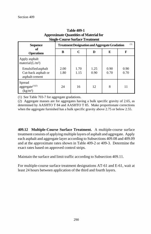
Section 409
290
Table 409-1Approximate Quantities of Material for
Single-Course Surface TreatmentSequence Treatment Designation and Aggregate Gradation
ofOperations
(1)
B C D E F
Apply asphaltmaterial (L/m²)
Emulsified asphalt 2.00 1.70 1.25 0.90 0.90Cut-back asphalt or 1.80 1.15 0.90 0.70 0.70asphalt cement
Spread aggregate 24 16 12 8 11(1)(2)
(kg/m²)
(1) See Table 703-7 for aggregate gradations.(2) Aggregate masses are for aggregates having a bulk specific gravity of 2.65, asdetermined by AASHTO T 84 and AASHTO T 85. Make proportionate correctionswhen the aggregate furnished has a bulk specific gravity above 2.75 or below 2.55.
409.12 Multiple-Course Surface Treatment. A multiple-course surfacetreatment consists of applying multiple layers of asphalt and aggregate. Applyeach asphalt and aggregate layer according to Subsections 409.08 and 409.09and at the approximate rates shown in Table 409-2 or 409-3. Determine theexact rates based on approved control strips.
Maintain the surface and limit traffic according to Subsection 409.11.
For multiple-course surface treatment designations AT-61 and E-61, wait atleast 24 hours between application of the third and fourth layers.
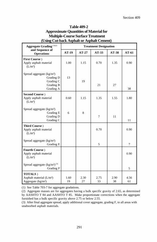
Section 409
291
Table 409-2Approximate Quantities of Material for
Multiple-Course Surface Treatment(Using Cut-back Asphalt or Asphalt Cement)
Aggregate Grading Treatment Designation(1)(2)
and Sequence ofOperations AT-19 AT-27 AT-33 AT-38 AT-61
First Course )Apply asphalt material
(L/m²)
Spread aggregate (kg/m²)Grading DGrading CGrading BGrading A
1.00 1.15 0.70 1.35 0.90
1319
21 2738
Second Course )Apply asphalt material
(L/m²)
Spread aggregate (kg/m²)Grading EGrading DGrading C
0.60 1.15 1.35 1.55 1.80
6 87 11
11
Third Course )Apply asphalt material
(L/m²)
Spread aggregate (kg/m²)Grading E
0.70 0.90
5 7
Fourth Course )Apply asphalt material
(L/m²)
Spread aggregate (kg/m²) (3)
Grading F
0.90
5
TOTALS )Asphalt material (L/m²)Aggregate (kg/m²)
1.60 2.30 2.75 2.90 4.5619 27 33 38 61
(1) See Table 703-7 for aggregate gradations.(2) Aggregate masses are for aggregates having a bulk specific gravity of 2.65, as determinedby AASHTO T 84 and AASHTO T 85. Make proportionate corrections when the aggregatefurnished has a bulk specific gravity above 2.75 or below 2.55.(3) After final aggregate spread, apply additional cover aggregate, grading F, to all areas withunabsorbed asphalt materials.
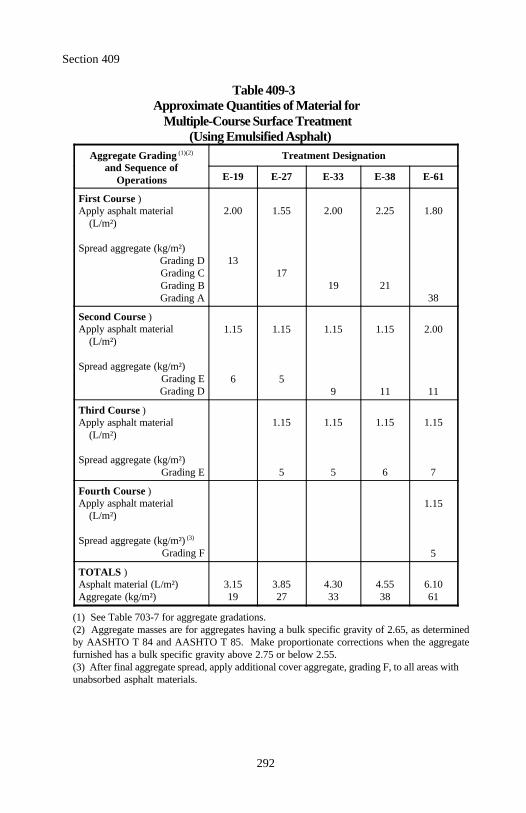
Section 409
292
Table 409-3Approximate Quantities of Material for
Multiple-Course Surface Treatment(Using Emulsified Asphalt)
Aggregate Grading Treatment Designation(1)(2)
and Sequence ofOperations E-19 E-27 E-33 E-38 E-61
First Course )Apply asphalt material
(L/m²)
Spread aggregate (kg/m²)Grading DGrading CGrading BGrading A
2.00 1.55 2.00 2.25 1.80
1317
19 2138
Second Course )Apply asphalt material
(L/m²)
Spread aggregate (kg/m²)Grading EGrading D
1.15 1.15 1.15 1.15 2.00
6 59 11 11
Third Course )Apply asphalt material
(L/m²)
Spread aggregate (kg/m²)Grading E
1.15 1.15 1.15 1.15
5 5 6 7
Fourth Course )Apply asphalt material
(L/m²)
Spread aggregate (kg/m²) (3)
Grading F
1.15
5
TOTALS )Asphalt material (L/m²)Aggregate (kg/m²)
3.15 3.85 4.30 4.55 6.1019 27 33 38 61
(1) See Table 703-7 for aggregate gradations.(2) Aggregate masses are for aggregates having a bulk specific gravity of 2.65, as determinedby AASHTO T 84 and AASHTO T 85. Make proportionate corrections when the aggregatefurnished has a bulk specific gravity above 2.75 or below 2.55.(3) After final aggregate spread, apply additional cover aggregate, grading F, to all areas withunabsorbed asphalt materials.
Section 409
293
409.13 Acceptance. Asphalt cement, emulsified asphalt, and cut-back asphaltwill be evaluated under Subsections 106.04 and 702.09.
Aggregate for asphalt surface treatment will be evaluated under Subsections106.02 and 106.04. See Table 409-4 for minimum sampling and testing re-quirements.
Construction of asphalt surface treatment course will be evaluated under Sub-sections 106.02 and 106.04.
Blotter will be evaluated under Section 411.
Measurement
409.14 Measure surface treatment aggregate by the metric ton or by the cubicmeter in the hauling vehicle.
Measure asphalt cement and emulsified asphalt by the metric ton.
Measure blotter under Section 411.
Payment
409.15 The accepted quantities, measured as provided above, will be paid atthe contract price per unit of measurement for the pay items listed below thatare shown in the bid schedule. Payments will be full compensation for thework prescribed in this Section. See Subsection 109.05.
Payment will be made under:
Pay Item Pay Unit
40901 Surface treatment aggregates designation ___ Metric ton40902 Surface treatment aggregates designation ___ Cubic meter40903 Asphalt cement grade ___ Metric ton40904 Emulsified asphalt grade ___ Metric ton
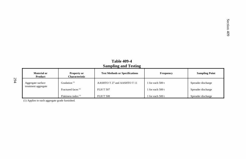
Section 409
294
Table 409-4Sampling and Testing
Material orProduct
Property orCharacteristic
Test Methods or Specifications Frequency Sampling Point
Aggregate surfacetreatment aggregate
Gradation (1)
Fractured faces (1)
Flakiness index (1)
AASHTO T 27 and AASHTO T 11
FLH T 507
FLH T 508
1 for each 500 t
1 for each 500 t
1 for each 500 t
Spreader discharge
Spreader discharge
Spreader discharge(1) Applies to each aggregate grade furnished.
295
Section 410.) SLURRY SEAL
Description
410.01 This work consists of applying an asphalt slurry seal mix.
Slurry seal type is designated as shown in Table 703-8.
Emulsified asphalt grade is designated as shown in AASHTO M 140 orAASHTO M 208.
Material
410.02 Conform to the following Subsections:
Aggregate 703.11Emulsified asphalt 702.03Mineral filler 725.05Water 725.01
Construction Requirements
410.03 Composition of Mix (Job-Mix Formula). Furnish a slurry seal mix-ture of aggregate, water, emulsified asphalt, and additives according to ASTMD 3910 and ISSA T 114. Conform to the applicable aggregate gradation inTable 703-8 and the following residual asphalt contents:
Type I - Residual asphalt between 10.0% and 16.0%
Type II - Residual asphalt between 7.5% and 13.5%
Type III - Residual asphalt between 6.5% and 12.0%
Submit a written job-mix formula for approval at least 21 days before produc-tion. Submit the following:
(a) Aggregate gradation values. The representative value for each sievesize for the aggregate blend.
(b) Emulsified asphalt content. The residual asphalt content, as a percentby mass of dry aggregate.
Section 410
296
(c) Aggregate samples. 45-kilogram sample of each aggregate.
(d) Emulsified asphalt sample. Source of and 20-liter sample of the emul-sified asphalt to be used in the mix. Furnish the sample in plastic containers.
(e) Mineral filler samples. 25-kilogram sample of each proposed mineralfiller, when applicable.
The job-mix formula will be evaluated for approval.
410.04 Equipment. Furnish equipment with the following capabilities:
(a) Slurry seal mixer.
(1) Self-propelled.(2) Continuous-flow mixing.(3) Calibrated controls.(4) Easily readable metering devices that accurately measure all raw mate-rial before entering the pugmill.(5) Automated system for sequencing in all raw material to ensure con-stant slurry mix.(6) Mixing chamber to thoroughly blend all ingredients together.(7) Fines feeder with an accurate metering device for introducing additiveinto the mixer where the aggregate is introduced into the mixer.(8) A pressurized water system with a fog-type spray bar capable of fog-ging the surface immediately ahead of the spreading equipment at a rateof 0.13 to 0.27 liters per square meter.(9) Proportioning system that is accurate for measuring all material inde-pendent of the engine speed.
(10) Minimum speed of 20 meters per minute and maximum speed of 55meters per minute.(11) Minimum storage capacity of 6 metric tons.(12) Capable according to ISSA Performance Guidelines A 105.
(b) Mechanical-type single squeegee spreader box.
(1) Attaches to the slurry seal mixer.(2) Flexible squeegee in contact with the surface to prevent loss of slurry.
Section 410
297
(3) Adjustable to assure a uniform spread over varying grades andcrowns.(4) Adjustable in width with a flexible strike-off.(5) Augers for uniform flow to edges.
(c) Auxiliary equipment. Furnish hand squeegees, shovels, and other equi-pment necessary to perform the work. Provide cleaning equipment includ-ing, but not limited to, power brooms, air compressors, water flushing equip-ment, and hand brooms for surface preparation.
410.05 Surface Preparation. Prepare the surface to be sealed according toSubsection 303.07.
410.06 Weather Limitations. Apply slurry seal when the air temperature inthe shade and the surface temperature are at least 15 C and rising and whenthe weather is not foggy, rainy, or overcast.
410.07 Slurry Seal Application. Mix the slurry seal using a slurry sealmixer. Fog the surface with water immediately preceding the spreader.
Blend the additive with the aggregate using the fines feeder. Pre-wet the aggre-gate in the pugmill immediately before mixing with the emulsified asphalt.
Mix the slurry seal a maximum of 4 minutes. Ensure the slurry seal mix is ofthe desired consistency as it leaves the mixer and conforms to the approvedjob-mix formula. Adjustment of the mineral filler and the emulsified asphaltcontent during construction may be approved to adjust for variations in fieldconditions.
Carry sufficient slurry seal mix in the spreader to completely cover the surface.Spread the mix with a mechanical-type single squeegee spreader box. In areasnot accessible to the spreader box, use hand squeegees to work the slurry sealmix.
Allow treated areas to completely cure before opening to traffic. Cure is com-plete when clear water can be pressed out of the slurry mix with a piece ofpaper without discoloring the paper.
410.08 Acceptance. Emulsified asphalt will be evaluated under Subsections106.04 and 702.09.
Section 410
298
Aggregate for slurry seal will be evaluated under Subsections 106.02 and106.04. See Table 410-1 for minimum sampling and testing requirements.
Construction of the slurry seal will be evaluated under Subsections 106.02 and106.04.
Measurement
410.09 Measure slurry seal by the square meter. Measure square meter widthhorizontally to include the top of surface width and allowable curve widening.Measure the square meter length horizontally along the centerline of the road-way.
Measure emulsified asphalt and slurry seal aggregate by the metric ton.
Payment
410.10 The accepted quantities, measured as provided above, will be paid atthe contract price per unit of measurement for the pay item listed below that isshown in the bid schedule. Payment will be full compensation for the workprescribed in this Section. See Subsection 109.05.
Payment will be made under:
Pay Item Pay Unit
41001 Slurry seal type ___ Square meter41002 Emulsified asphalt grade ___ Metric ton41003 Slurry seal aggregate Metric ton
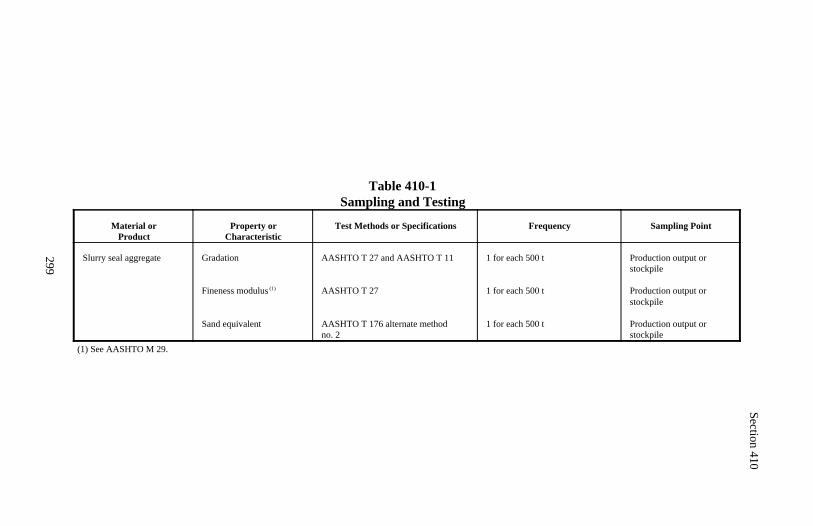
Section 410
299
Table 410-1Sampling and Testing
Material orProduct
Property orCharacteristic
Test Methods or Specifications Frequency Sampling Point
Slurry seal aggregate Gradation
Fineness modulus (1)
Sand equivalent
AASHTO T 27 and AASHTO T 11
AASHTO T 27
AASHTO T 176 alternate method no. 2
1 for each 500 t
1 for each 500 t
1 for each 500 t
Production output orstockpile
Production output orstockpile
Production output orstockpile
(1) See AASHTO M 29.
300
Section 411.) ASPHALT PRIME COAT
Description
411.01 This work consists of applying a cut-back or emulsified asphalt primecoat.
Prime coat asphalt grade is designated as shown in AASHTO M 140 orAASHTO M 208 for emulsified asphalt and AASHTO M 81 or AASHTO M82 for cut-back asphalt.
Material
411.02 Conform to the following Subsections:
Blotter 703.13Cut-back asphalt 702.02Emulsified asphalt 702.03
Construction Requirements
411.03 Equipment. Use equipment conforming to Subsection 409.04.
411.04 Surface Preparation. Prepare the surface to be primed according toSubsection 303.07.
411.05 Weather Limitations. Apply prime coat on a dry or slightly dampsurface when the air temperature in the shade and the pavement surface temper-ature are at least 10 C and rising and when the weather is not foggy or rainy.
411.06 Asphalt Application. When required, lightly spray the surface withwater before applying the prime coat. Apply asphalt according to Subsection409.08 at a rate of 0.45 to 2.25 liters per square meter for optimum penetration.
Where using an emulsified asphalt that is not formulated as a penetrating primecoat material, dampen the roadway surface and scarify 25 to 50 millimetersdeep. When required, dilute a slow-setting emulsified asphalt by adding anequal amount of water. Apply the emulsified asphalt at a rate of 0.45 to 1.35liters per square meter. Immediately process, respread, and compact the mate-rial.
Section 411
301
Cure surfaces primed with emulsified asphalt for not less than 24 hours andsurfaces primed with cut-back asphalt for not less than 3 days before coveringwith the next course.
Until the next course is placed, maintain the primed surface and keep it free ofcorrugations by broom dragging.
Where traffic is routed over a primed surface before the asphalt material hasbeen completely absorbed, or to minimize damage by rain, spread blotter tocover the unabsorbed asphalt. Remove excess blotter as soon as practicableafter excess asphalt is absorbed. Remove all dirt or other deleterious materialand repair all damaged areas before placing the next course. 411.07 Acceptance. Emulsified asphalt and cut-back asphalt will be evalu-ated under Subsections 106.04 and 702.09.
Aggregate for blotter will be evaluated under Subsection 106.03.
Construction of the prime coat will be evaluated under Subsections 106.02 and106.04.
Surface preparation will be evaluated under Section 303.
Measurement
411.08 Measure prime coat asphalt by the metric ton or by the liter includingwater added for dilution.
Measure blotter by the metric ton or by the cubic meter in the hauling vehicle.
Payment
411.09 The accepted quantities, measured as provided above, will be paid atthe contract price per unit of measurement for the pay items listed below thatare shown in the bid schedule. Payments will be full compensation for thework prescribed in this Section. See Subsection 109.05.

Section 411
302
Payment will made under:
Pay Item Pay Unit
41101 Prime coat grade ___ Metric ton41102 Prime coat grade ___ Liter41103 Blotter Metric ton41104 Blotter Cubic meter
303
Section 412.) ASPHALT TACK COAT
Description
412.01 This work consists of applying an emulsified asphalt tack coat.
Tack coat emulsified asphalt grade is designated as shown in AASHTO M 140or AASHTO M 208.
Material
412.02 Conform to the following Subsection:
Emulsified asphalt 702.03
Construction Requirements
412.03 Equipment. Use equipment conforming to Subsection 409.04.
412.04 Surface Preparation. Prepare the surface for a tack coat accordingto Subsection 303.07. When the surface is concrete, remove excess joint andcrack filler.
412.05 Weather Limitations. Apply asphalt tack coat on a dry, unfrozensurface when the air temperature in the shade is above 2 C and rising.
412.06 Asphalt Application. Where using slow-setting emulsified asphalt,dilute by adding an equal amount of water to the emulsified asphalt.
Apply the asphalt according to Subsection 409.08 at a rate of 0.15 to 0.70 litersper square meter. When a tack coat cannot be applied with an asphalt distribu-tor spray bar, apply the tack coat uniformly and completely by fogging with ahand spray attachment or by another approved method.
If excess asphalt material is applied, squeegee the excess from the surface.Allow the tacked surfaces to completely cure before placing the coveringcourse. Place the covering course within 4 hours of placing the tack coat.
Section 412
304
412.07 Acceptance. Emulsified asphalt will be evaluated under Subsections106.04 and 702.09.
Construction of the tack coat will be evaluated under Subsections 106.02 and106.04.
Surface preparation will be evaluated under Section 303.
Measurement
412.08 Measure tack coat by the metric ton or by the liter including wateradded for dilution.
Payment
412.09 The accepted quantities, measured as provided above, will be paid atthe contract price per unit of measurement for the pay items listed below thatis shown in the bid schedule. Payment will be full compensation for the workprescribed in this Section. See Subsection 109.05.
Payment will be made under:
Pay Item Pay Unit
41201 Tack coat grade ___ Metric ton41202 Tack coat grade ___ Liter
305
Section 413.) ASPHALT PAVEMENT MILLING
Description
413.01 This work consists of removing asphalt pavement by a cold millingprocess.
Construction Requirements
413.02 Equipment ) Milling Machine. Furnish equipment with the followingcapabilities:
(a) Self-propelled.(b) Sufficient power, traction, and stability to accurately maintain depth ofcut.(c) Capable of removing the pavement thickness to provide profile and cross slope.(d) Automatic system to control grade elevations by referencing from theexisting pavement by means of a ski or matching shoe or from an inde-pendent grade control.(e) Automatic system to maintain cross slope.(f) System to effectively limit dust and other particulate matter from es caping removal operations.(g) Loading system or adequate support equipment to completely recover milled material at removal rate.(h) Cutting width equal to at least one third of the lane width.
413.03 Milling. Use a longitudinal reference to accurately guide the machine.References may include a curb, edge of pavement, or string attached to thepavement surface. Mill in a longitudinal direction.
Mill the transverse slope to within 6 millimeters in 3 meters of the requiredslope. Transition from one transverse slope to another at a uniform rate.Uniformly mill the entire roadway lane width so the cross-section of the newsurface forms a straight line.
Transition between different depths of cut at a uniform rate of 17 millimetersof depth per 10 meters . At the beginning and end of the milling work, con-struct a smooth transition to the original surface at this rate. Do not leave anexposed vertical edge perpendicular to the direction of travel. When the pave-ment remains open to traffic, limit differences in elevation between adjacentlanes according to Subsection 156.06(b).
Section 413
306
Mill the surface to a smoothness conforming to Subsection 402.08.
Use a rotary broom and vacuum immediately behind the milling operations toremove and completely recover all loose material. Minimize the escape of dustinto the air. Dispose of recovered milled material according to Subsection 211.03(b).
Before opening to traffic, patch milled travel lanes according to Subsection635.17.
413.04 Acceptance. Asphalt pavement milling will be evaluated under Sub-sections 106.02 and 106.04.
Smoothness of milled surface will be evaluated under Section 402.
Measurement
413.05 Measure asphalt pavement milling by the square meter or by the kilo-meter. Measure square meter width horizontally. Measure the length horizon-tally along the centerline of the roadway.
Payment
413.06 The accepted quantities, measured as provided above, will be paid atthe contract price per unit of measurement for the pay items listed below thatare shown in the bid schedule. Payments will be full compensation for thework prescribed in this Section. See Subsection 109.05.
Payment will be made under:
Pay Item Pay Unit
41301 Asphalt pavement milling, ___ millimeter depth Square meter41302 Asphalt pavement milling, ___ millimeter depth Kilometer
307
Section 414.) ASPHALT PAVEMENTCRACK AND JOINT SEALING
Description
414.01 This work consists of saw cutting, when required in the contract, andcleaning and filling cracks and joints in asphalt pavement.
Material
414.02 Conform to the following Section and Subsections:
Asphalt cement 702.01Blotter 703.13Emulsified asphalt 702.03Fine aggregate 703.01Joint sealant 712.01(a)Slurry seal 410
Construction Requirements
414.03 Equipment. Furnish equipment with the following capabilities:
(a) Power saw and blades. Saw and blades of such size and configurationthat saw cuts can be made with one pass. Spacers are not allowed.
(b) Router. Power rotary impact router or vertical spindle router capable ofcleaning cracks or joints to the required depth and width.
(c) Hot-compressed air lance. A lance capable of providing clean, oil-freecompressed air at a volume of 2.8 cubic meters per minute at a pressure of830 kilopascals and at a temperature of 1000 C.
(d) Application wand. A crack sealant applicator wand attached to a heatedhose that is attached to a heated sealant chamber. The temperature controlsshall maintain temperature of the sealant within manufacturer's tolerances.
Section 414
308
(e) Heating kettle. An indirect-heating-type double boiler with the spacebetween the inner and outer shells filled with oil or other heat transfer me-dium capable of constant agitation. Provide an accurate and calibrated ther-mometer having a range from 100 to 300 C in 2 C graduations. Locate thethermometer such that the temperature of the joint sealant may be safelychecked.
(f) Squeegee. A hand-held squeegee for ensuring that the crack is filled tothe existing surface.
414.04 Saw Cutting and Joint Sealing. Saw cut, clean, and seal joints in acontinuous operation. Either dry or wet cutting is allowed.
Clean dry-sawed joints with a stream of air sufficient to remove all dirt, dust,or deleterious matter adhering to the joint walls or remaining in the joint cavity.Blow or brush dry material off the pavement surface.
Clean wet-sawed joints with a water blast, 350 kilopascals minimum, imme-diately after sawing to remove any sawing slurry, dirt, or deleterious matteradhering to the joint walls or remaining in the joint cavity. Immediately flushall sawing slurry from the pavement surface. Blow wet-sawed joints with airto dry joint surfaces.
Do not allow traffic to knead together or damage the sawed joints. If cleaningoperations cause interference with traffic, provide protective screening.
Place the sealant when the pavement surface temperature is 4 C or higher.Discontinue operations when weather conditions detrimentally affect the qual-ity of forming joints and applying sealants.
Submit a copy of and adhere to the manufacturer's recommendations for heat-ing and applying the joint sealant. Heat the joint sealant in a heating kettle. Donot heat the sealant above the safe heating temperature recommended by themanufacturer. Do not hold the material at the pouring temperature for morethan 6 hours and do not reheat the material.
Place a bond breaker tape designed for use with hot poured sealant in the bot-tom of the saw cut joint.
Section 414
309
Seal the joints with an applicator wand when the sealant material is at thepouring temperature. Heat or insulate the applicator wand to maintain thepouring temperature of the sealant during placing operation. Return the app-licator wand to the machine and recirculate the joint sealant material imme-diately after sealing each joint.
Fill each joint such that, after cooling, the level of the sealant is no more than3 millimeters below the pavement surface.
Wait for the sealant to be tack free before opening the joint to traffic. Do notspread blotter on the sealed joints to allow early opening to traffic.
414.05 Crack Cleaning and Sealing. Clean the existing surface of all loosematerial, dirt, or other deleterious substances by brooming, flushing with water,or other approved methods. Rout and clean all cracks with an average openingof 6 millimeters or more to make a sealant reservoir to the depth of the routedcrack or at least 20 millimeters deep. Dry cracks before sealing.
When using the hot-compressed air lance, keep it moving so as not to burn thesurrounding pavement and the joint. Place and finish sealant within 5 minutesafter heating with the hot-compressed air lance.
For cracks with a 13 millimeter width or less, seal with hot-poured elasticsealant according to Subsection 414.04.
For cracks with a width greater than 13 millimeters, seal with an approvedslurry seal mix, fine aggregate-asphalt cement mix, or fine aggregate-emul-sified asphalt mix. Use a squeegee or other suitable equipment to force the mixinto the cracks.
Immediately screed the joint sealant or asphalt mix to the elevation of theexisting surface. Use a squeegee to ensure that a 75-millimeter wide band iscentered on the finished sealed crack. Cover the sealed crack with a lightapplication of blotter.
414.06 Resealing Defective Joints or Cracks. Reseal areas exhibiting adhe-sion failure, damage, missed areas, foreign objects in the sealant, or otherproblems which will accelerate failure.
Section 414
310
414.07 Acceptance. Material for asphalt pavement crack and joint sealingwill be evaluated under Subsections 106.02 and 106.03.
Asphalt pavement crack and joint sealing will be evaluated under Subsection106.04.
Measurement
414.08 Measure joint sealant by the liter or by the kilogram.
Measure saw cutting and joint sealing, and crack cleaning and sealing by themeter.
Payment
414.09 The accepted quantities, measured as provided above, will be paid atthe contract price per unit of measurement for the pay items listed below thatare shown in the bid schedule. Payments will be full compensation for thework prescribed in this Section. See Subsection 109.05.
Payment will be made under:
Pay Item Pay Unit
41401 Joint sealant Liter41402 Joint sealant Kilogram41403 Saw cutting and joint sealing Meter41404 Crack cleaning and sealing Meter
311
Section 415.) PAVING GEOTEXTILES
Description
415.01 This work consists of furnishing and placing a paving geotextile andasphalt sealant between pavement layers to form a waterproofing and stress-relieving membrane within the pavement structure.
Material
415.02 Conform to the following Subsections:
Asphalt cement 702.01Blotter 703.13Emulsified asphalt 702.03Geotextile type VI 714.01Joint sealant 712.01(a)
Construction Requirements
415.03 Surface Preparation. Prepare the surface to receive the geotextilefabric according to Subsection 303.07.
415.04 Weather Limitations. Apply asphalt sealant and paving geotextile ona dry surface when the pavement surface temperature is at least 13 C andrising.
415.05 Asphalt Sealant Application. Use asphalt cements within a tempera-ture range of 140 to 165 C. Use emulsified asphalts within a temperaturerange of 55 to 70 C.
Apply the asphalt sealant to the pavement surface according to Subsection409.08 at a rate of 0.90 to 1.35 liters per square meter.
Spray the asphalt sealant 150 millimeters wider than the paving geotextile. Donot apply the asphalt sealant any farther in advance of the paving geotextileplacement than can be maintained free of traffic.
Where emulsified asphalt is used, allow the emulsion to break before placingthe paving geotextile.
Section 415
312
Where asphalt cement is used, place the paving geotextile before the asphalthas cooled and lost tackiness.
415.06 Paving Geotextile Placement. Place the paving geotextile onto theasphalt sealant with minimal wrinkling. Slit, lay flat, and tack all wrinkles orfolds higher than 25 millimeters. Broom and/or roll the paving geotextile tomaximize fabric contact with the pavement surface.
At geotextile joints, overlap the geotextile 6 inches (150 millimeters to ensurefull closure. Overlap transverse joints in the direction of paving to preventedge pickup by the paver. Apply additional asphalt sealant to paving geotextileoverlaps to ensure proper bonding of the double fabric layer.
If asphalt sealant bleeds through the fabric, treat the affected areas with blotter.Minimize traffic on the geotextile. If circumstances require traffic on themembrane, apply blotter and place "slippery when wet" signs.
Broom the excess blotter from the geotextile surface before placing the over-lay. Repair all damaged fabric before placing overlay. Apply a light tack coataccording to Section 412 before placing the overlay. To avoid damaging thegeotextile, do not turn equipment on the geotextile.
Place a hot asphalt concrete overlay within 48 hours after placing the pavinggeotextile. Limit the lay-down temperature of the mix to a maximum of 165
C except when the paving geotextile is composed of polypropylene fibers,limit the lay-down temperature of the mix to a maximum of 150 C. 415.07 Acceptance. Asphalt cement will be evaluated under Subsections106.04 and 702.09. Geotextile material will be evaluated under Subsections106.02, 106.03, and 714.01.
Placement of the paving geotextile will be evaluated under Subsections106.02 and 106.04.
Blotter will be evaluated under Section 411.
Surface preparation will be evaluated under Section 303.
Section 415
313
Measurement
415.08 Measure paving geotextile by the square meter excluding overlaps.
Measure asphalt sealant by the metric ton.
Measure blotter under Section 411.
Payment
415.09 The accepted quantities, measured as provided above, will be paid atthe contract price per unit of measurement for the pay items listed below thatare shown in the bid schedule. Payments will be full compensation for thework prescribed in this Section. See Subsection 109.05.
Payment will be made under:
Pay Item Pay Unit
41501 Paving geotextile Square meter41502 Asphalt sealant Metric ton
314
Section 416.) CONTINUOUS COLD RECYCLEDASPHALT BASE COURSE
Description
416.01 This work consists of constructing a recycled asphalt base course usingmethods and equipment capable of recycling and relaying the material in a one-pass operation.
Continuous cold recycled asphalt base course compaction is designated typeA or B as shown in Subsection 416.08.
Emulsified asphalt grades for emulsified binder agent and sealing emulsion aredesignated as shown in AASHTO M 140 or AASHTO M 208.
Material
416.02 Conform to the following Subsections:
Emulsified binder agent 702.03Quicklime 725.03Recycling agent 702.06Sealing emulsion 702.03Water 725.01
Construction Requirements
416.03 Submittals.
(a) Material. When type A compaction is designated, submit the followingat least 28 days before recycling:
(1) Ten pavement cores at least 150 millimeters in diameter from ran-domly selected sites(2) Source of and 7 liters of emulsified binder agent(3) One kilogram of quicklime if quicklime is included in the bidschedule(4) Material safety data sheets
The CO will perform a mix design and provide an initial application rate foremulsified binder agent, recycling agent, and quicklime, as applicable.
Section 416
315
(b) Specialty qualifications. At least 14 days before recycling, submit thename, qualifications, and references of a competent person with extensiverecycling experience to be responsible for the recycling operations. Thisindividual's responsibilities are identified in Subsection 416.07(c).
(c) Sequence of operations. At least 14 days before recycling, submit theproposed equipment, manpower, and sequence of operations.
416.04 Surface Preparation. Prepare the surface according to Subsection303.07(c). Clear, grub, and remove all vegetation and debris within 0.5 meterof the pavement to be recycled.
416.05 Weather Limitations. See Subsection 406.06.
416.06 Pavement Milling. Use equipment that is:
(a) Self-propelled
(b) Equipped with automatic depth controls
(c) Capable of maintaining the required cutting depth
(d) Capable of milling to the required depth in a single pass, half the existingpavement width or one lane width, whichever is greater
(e) Capable of screening and crushing material
Do not disturb underlying material.
Reduce oversize particles to a maximum size of 25.0 millimeters.
416.07 Mixing and Proportioning. Produce a homogeneous and uniformly-coated mixture of milled paving material, emulsified binder agent, and water.
(a) Equipment. Use self-propelled equipment with:
(1) A positive displacement pump with an automatic interlock systemwhich allows the addition of emulsified binder agent and/or recyclingagent only when milled material is present in the mixing chamber andautomatically shuts off when the machine is stopped. The pump must be
Section 416
316
capable of supplying from 0 to 10 percent emulsified binder agent bymass of aggregate to within ±0.1 percent of the desired application rate.
(2) A weighing device calibrated and synchronized with the emulsifiedbinder agent metering pump to regulate the emulsified binder agent addedto the material in the mixing chamber.
(3) A meter for monitoring flow rate and total delivery of emulsifiedbinder agent and/or recycling agent into the mix.
(b) Quicklime. When there is an item in the bid schedule for quicklime, in-corporate quicklime using one of the following methods:
(1) Dry. Use a calibrated spreader to place pelletized quicklime on theexisting pavement ahead of the recycling operation. Place quicklimewithin the width of the milling head. After milling, add sufficient waterto slake the quicklime.
(2) Slurry. Use mixing equipment designed for producing lime slurries.Equip the slurry plant operations with scales and meters to proportionquicklime and water within 0.5 percent by mass. Agitate the transporttanks to keep the lime in suspension. Provide a consistent pumpable limeslurry with the appropriate amount of quicklime to be incorporated intothe recycled asphalt pavement. Introduce the lime slurry at the millinghead. Meter lime slurry to within ±10 percent of the required amount.
(c) Monitoring. Continuously monitor and evaluate the milling/ mix-ing/placing operations and make adjustments to proportioning or operationalprocedures as appropriate to maximize the quality and serviceability of thefinal recycled asphalt base product. Adjustments may include the applica-tion rate for emulsified binder agent, application of quicklime, applica-tion of water, changes to the recycling operation to address distinct variationsin existing pavement and material conditions, changes due to variation inshoulder material, and termination of operations due to abnormal or ques-tionable product.
416.08 Spreading, Finishing, and Compacting. Use a paver conforming toSubsection 401.05 that is capable of picking up the entire windrow and feedingit into the paver hopper. Do not heat the screed.
Section 416
317
Place, spread, and strike off the recycled mix to the required line, grade, andelevation.
(a) Initial compaction. Compact using the designated type:
(1) Type A. One to 2 hours after placing the recycled mix, compact therecycled mix according to Subsection 401.14 except use pneumaticroller(s) weighing at least 27 metric tons. Do not park or idle rollers onuncompacted recycled material. Initially compact with pneumatic rollersuntil no displacement is visible. Use steel-wheel roller(s), either in staticor vibratory mode, to achieve final density.
Compact the recycled mix until it obtains a minimum density, immedi-ately after placing and rolling, of 88 percent of a laboratory specimenprepared according to AASHTO T 247 at 60 C. Measure the density ofthe laboratory specimen according to AASHTO T 166. Measure thedensity of the inplace recycled mix according to AASHTO T 238.
(2) Type B. Compact the recycled mix using the following equipment,sequence, and number of roller passes:
(a) 6 to 8 roller passes with a double drum, vibratory roller havinga minimum mass of 5.5 metric tons and equipped with frequencyand amplitude controls.
(b) 8 to 12 roller passes with a pneumatic-tired roller having a mini-mum mass of 900 kilograms per wheel and a contact pressure of550 kilopascals.
(c) 4 to 6 roller passes with a static steel-wheel roller with a mini-mum pressure of 1.7 megapascals.
Keep all traffic and equipment off of the recycled asphalt base for at least 2hours after completing initial compaction.
(b) Pavement smoothness. Immediately after initial compaction is com-plete, measure pavement smoothness according to Subsection 401.16(b),except defective areas are surface deviations in excess of 10 millimeters in3 meters. Correct defective areas according to Subsection 401.16(c).
Section 416
318
(c) Final compaction. Compact using the designated type:
(1) Type A. Before the next surfacing course is placed, compact therecycled mix until it obtains a minimum density of 92 percent of the labo-ratory specimen.
(2) Type B. At least 3 days after initial compaction, continue compactiveeffort with the pneumatic and static steel wheel rollers when the surfacetemperature is greater than 22 C. Use a minimum of four passes over theentire surface with each roller.
(d) Curing. Repair damage to the recycled asphalt base.
(1) Recycled mix with quicklime. Overlay the recycled base within 21days after recycling.
(2) Recycled mix without quicklime. Overlay after the recycled basehas cured 7 to 21 days. Do not overlay until the moisture content of therecycled base is less than or equal to 1.5 percent according to AASHTOT 239 or until 21 days after recycling.
416.09 Sealing Emulsion. When there is a pay item for sealing emulsion inthe bid schedule and when directed by the CO, place a sealing emulsion on thesurface of the recycled base after final compaction. Dilute the sealing emulsion50 percent by volume with water and apply it at a rate of 0.20 to 0.90 liters persquare meter. Place blotter according to Section 411.
416.10 Acceptance. Emulsified binder material will be evaluated under Sub-sections 106.03, 106.04, and 702.09.
Quicklime will be evaluated under Subsection 106.03.
Construction of continuous cold recycled asphalt base course will be evaluatedunder Subsections 106.02 and 106.04. Type A compaction will be evaluatedunder Subsection 106.04. See Table 416-1 for minimum sampling and testingrequirements.
Pavement smoothness will be evaluated under Subsections 106.02 and106.04.
Blotter material will be evaluated under Section 411.
Section 416
319
Measurement
416.11 Measure cold recycled asphalt base course by the kilometer or by thesquare meter. Measure square meter width horizontally to include the top ofbase width and allowable curve widening. Measure the square meter lengthhorizontally along the centerline of the roadway.
Measure emulsified binder agent by the metric ton.
Measure sealing emulsion by the metric ton including water used fordilution.
Payment
416.12 The accepted quantities, measured as provided above, will be paid atthe contract price per unit of measurement for the pay items listed below thatare shown in the bid schedule. Payment will be full compensation for the workprescribed in this Section. See Subsection 109.05.
Payment will be made under:
Pay Item Pay Unit
41601 Continuous cold recycled asphalt Kilometerbase course type ___
41602 Continuous cold recycled asphalt Square meterbase course type ___
41603 Emulsified binder agent grade ___ Metric ton41604 Sealing emulsion grade ___ Metric ton41605 Quicklime Metric ton
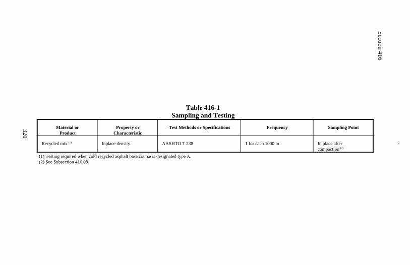
Section 416
320
Table 416-1Sampling and Testing
Material orProduct
Property orCharacteristic
Test Methods or Specifications Frequency Sampling Point
Recycled mix (1) Inplace density AASHTO T 238 1 for each 1000 m 2In place aftercompaction (2)
(1) Testing required when cold recycled asphalt base course is designated type A.(2) See Subsection 416.08.
321
Section 417.) MINOR COLD ASPHALT MIX
Description
417.01 This work consists of furnishing and placing one or more courses ofcold asphalt mix. This work also consists of furnishing and placing cold as-phalt mix as a patching material for temporary roadway maintenance.
Material
417.02 Conform to the following Subsection:
Cold asphalt mix 702.10
Construction Requirements
417.03 Composition of Mix (Job-Mix Formula). Submit the strength, qual-ity, and gradation specifications for the cold asphalt mix. Include copies oflaboratory test reports that demonstrate the properties of the aggregates, asphaltcement, additives, and mix meet Federal or state agency specifications.
417.04 Surface Preparation. Prepare the surface according to Section 209or Subsection 303.07 as applicable.
417.05 Placing. Place the mix with appropriate equipment to produce a uni-form surface. For roadway paving, do not place lifts thicker than 100 millime-ters. In areas where mechanical spreading and finishing is impractical, spreadand finish each course by hand raking, screeding, or by other approved meth-ods. Construct a surface that is uniform in texture and cross-section. Constructjoints or tapers as required.
417.06 Compacting.
(a) Roadway paving. Compact by rolling with a steel-wheeled roller weigh-ing at least 8 metric tons.
(b) Non-roadway paving and patching. Compact by rolling with a hand-operated roller weighing at least 130 kilograms or with a small power roller.
Compact areas that are not accessible to rollers by other approved methods.
Section 417
322
417.07 Acceptance. Minor cold asphalt mix will be evaluated under Sub-sections 106.02 and 106.03.
Minor cold asphalt mix construction work will be evaluated under Subsections106.02 and 106.04.
Measurement
417.08 Measure minor cold asphalt mix by the metric ton.
Payment
417.09 The accepted quantities, measured as provided above, will be paid atthe contract price per unit of measurement for the pay item listed below that isshown in the bid schedule. Payment will be full compensation for the workprescribed in this Section. See Subsection 109.05.
Payment will be made under:
Pay Item Pay Unit
41701 Minor cold asphalt mix Metric ton
323
DIVISION 500Portland Cement
Concrete Pavement
324
Section 501.) PORTLAND CEMENTCONCRETE PAVEMENT
Description
501.01 This work consists of constructing portland cement concrete pavementon a prepared surface. This work also includes pavement rehabilitation con-sisting of full-depth, full-width removal and reconstruction of portland cementconcrete pavement.
Material
501.02 Conform to the following Subsections:
Air-entraining admixtures 711.02Chemical admixtures 711.03Coarse aggregate 703.02Curing material 711.01Epoxy resin adhesives 725.21Fine aggregate 703.01Fly ash 725.04Grout 725.22Joint fillers and sealants 712.01Portland cement 701.01Reinforcing steel, tie bars, dowel bars, hook bolts, caps 709.01Water 725.01
Construction Requirements
501.03 Composition of Mix (Concrete Mix Design). Design the concretemix according to Subsection 552.03. Conform to Table 501-1.
501.04 Equipment. Furnish equipment conforming to the following:
(a) Forms. Furnish straight, steel forms. For edge radii less than 60 meters,furnish flexible or curved forms. Conform to all the following:
(1) Depth equal to edge of pavement thickness (2) 3-meter minimum length(3) Stabilizing devices to withstand paving operations(4) Joint locks to join form lengths tightly together(5) Cleaned and oiled before each use
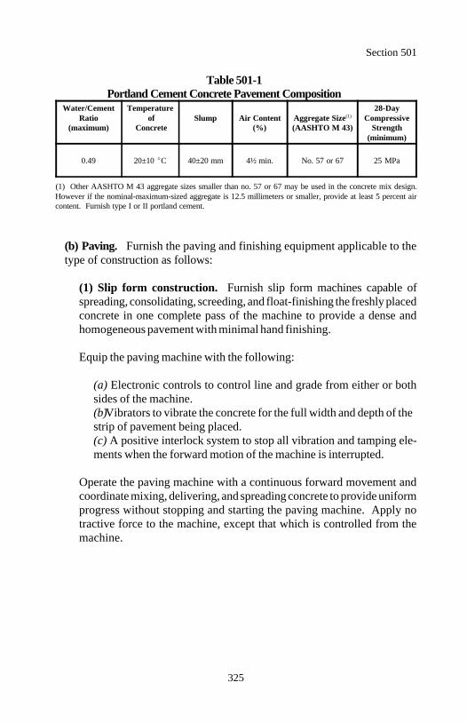
Section 501
325
Table 501-1Portland Cement Concrete Pavement Composition
Water/Cement Temperature 28-DayRatio of Slump Air Content Aggregate Size Compressive
(maximum) Concrete (%) (AASHTO M 43) Strength(1)
(minimum)
0.49 20±10 C 40±20 mm 4½ min. No. 57 or 67 25 MPa
(1) Other AASHTO M 43 aggregate sizes smaller than no. 57 or 67 may be used in the concrete mix design.However if the nominal-maximum-sized aggregate is 12.5 millimeters or smaller, provide at least 5 percent aircontent. Furnish type I or II portland cement.
(b) Paving. Furnish the paving and finishing equipment applicable to thetype of construction as follows:
(1) Slip form construction. Furnish slip form machines capable ofspreading, consolidating, screeding, and float-finishing the freshly placedconcrete in one complete pass of the machine to provide a dense andhomogeneous pavement with minimal hand finishing.
Equip the paving machine with the following:
(a) Electronic controls to control line and grade from either or bothsides of the machine.(b) Vibrators to vibrate the concrete for the full width and depth of thestrip of pavement being placed.(c) A positive interlock system to stop all vibration and tamping ele-ments when the forward motion of the machine is interrupted.
Operate the paving machine with a continuous forward movement andcoordinate mixing, delivering, and spreading concrete to provide uniformprogress without stopping and starting the paving machine. Apply notractive force to the machine, except that which is controlled from themachine.
Section 501
326
(2) Side form construction. Furnish mechanical, self-propelled sp-reading and finishing machines capable of compacting and finishing theconcrete with minimal hand finishing. Equip the machine with one 450-millimeter minimum width screed with compensating springs to minimizethe effect of the screed's momentum on the side forms, or 2 independentlyoperated screeds.
Coordinate the number of driving wheels, power of the motor, and themachine's mass to prevent slippage. Any machine which displaces theside forms will not be permitted.
(3) Vibrators. Furnish internal immersed tube or multiple spud typevibrators for all paving more than 200 millimeters thick. Surface pan typevibrators are acceptable for full-width concrete consolidation of slabs 200millimeters or less in thickness. Attach vibrators to the spreader or finish-ing machine or mount on a separate carriage. For construction of irregu-lar areas, use hand held vibrators according to Subsection 552.11(d).
(c) Joint sealing. Furnish sealing equipment according to the sealant manu-facturer's recommendations.
(d) Joints and concrete removal. Furnish an adequate supply of concretesaws with sufficient power to saw full-depth and complete the work withwater-cooled, diamond-edged blades, or abrasive wheels. Equip saws withblade guards and guides or devices to control alignment and depth. Furnishand maintain stand-by equipment and an adequate supply of replacementblades or wheels.
(e) Concrete removal. Furnish concrete saws, drop hammers, hydrohamm-ers, and jack hammers to break concrete. Concrete saws shall conform to (d)above. Ball-drop breakers are not permitted.
Furnish equipment that will not damage the subgrade, subbase, base, orexisting concrete slabs designated to remain.
If new or existing slabs, not scheduled for replacement, are chipped, spalled,or damaged during the removal operations, replace the damaged slabs.
Section 501
327
501.05 Preparing Roadbed. Prepare the roadbed according to Subsection303.07. Uniformly dampen the roadbed before placing the concrete. If trafficis allowed to use the prepared roadbed, check and correct the surface imme-diately before the concrete is placed.
Full-depth, full-width reconstruction shall conform to Subsection 501.13.
501.06 Placing Concrete. For storing, handling, batching, and mixing materi-al and delivering concrete, conform to Subsections 552.04 through 552.08 and552.10.
Do not place concrete on frozen subgrade. Place concrete with side form orslip form paving machines. Where a paving machine is impractical, placeconcrete according to Subsection 501.07.
When concrete is placed adjoining a previously constructed lane of pavement,do not allow mechanical equipment to be operated on the existing lane, untilthe lane has attained a minimum flexural strength of 3.8 megapascals accordingto AASHTO T 97 or compressive strength of 24 megapascals according toAASHTO T 22. Protect the previously constructed lane from damage by thepaving equipment.
Construct reinforcing steel according to Section 554. Firmly position thereinforcement on acceptable supports before placing the concrete, or afterspreading, mechanically place or vibrate the reinforcement to the requireddepth in the plastic concrete.
501.07 Construction of Irregular Areas. In irregular areas or areas inacces-sible to paving equipment, construct the pavement using side forms. Strike-off,consolidate, float, and surface finish the concrete, as follows:
(a) Thoroughly and uniformly vibrate and compact the concrete during place-ment without segregating the material.
(b) Using templates or screeds, strike-off the concrete to shape it to the re-quired cross-section between the forms. Carry a slight excess of concrete infront of the leading edge of the template or screed.
(c) Float the surface to the required grade and cross-section.
(d) Finish the surface according to Subsection 501.09.
Section 501
328
501.08 Joints. Do not vary longitudinal joints more than 13 millimeters andtransverse joints more than 6 millimeters from the true alignment. When curbsor medians are constructed integral with the pavement, construct transversejoints continuous through the curb or median. Protect all joints from the intru-sion of deleterious matter until sealed.
Form isolated joints at structures by placing 13-millimeter expansion joint filleraround each structure that extends into or through the pavement before con-crete is placed.
Remove and replace all newly placed concrete pavement where uncontrolledcracking occurs.
(a) Longitudinal joints. Construct longitudinal joints by forming or sawing.Construct sawed longitudinal joints (with tie bars) when the concrete pave-ment placement width exceeds 4.5 meters. Construct the longitudinal jointcontinuous with no gaps in either the transverse or longitudinal joints atintersections.
Place tie bars perpendicular to the longitudinal joints with mechanical equip-ment or rigidly secured chairs without damaging or disrupting the concrete.Do not paint or coat tie bars with any material or enclose them in tubes orsleeves.
Where adjacent lanes of pavement are constructed separately, use slip formpaving machines or steel side forms to form a keyway along the constructionjoint. Tie bars may be bent at right angles against the form of the first laneconstructed and straightened into final position before placing concrete in theadjacent lane. Repair or replace broken or badly damaged tie bars.
Threaded hook bolts may be used instead of tie bars. Fasten hook bolts tothe form of the longitudinal construction joint. With slip form paving, tiebars may be hydraulically inserted through metal keyways.
(1) Formed joints. Form joints with an approved nonmetallic or remov-able device while the concrete is plastic. When adjacent lanes are con-structed separately, form the sealant reservoir in the lane placed last.
Section 501
329
(2) Sawed joints. After placing concrete, saw joints as soon as equip-ment can be supported and before uncontrolled cracking occurs. Do notravel the joints while sawing. Saw longitudinal joints immediately aftersawing transverse joints. Protect the sawed concrete faces from dryingduring the curing period. Saw sealant reservoirs no sooner than 72 hoursafter placing the concrete.
If necessary, continue sawing day and night, regardless of weather condi-tions. Clean the saw cut and adjacent concrete surface of slurry residueafter sawing each joint.
Do not saw a joint if a crack occurs at or near the joint location beforesawing. Discontinue sawing when a crack develops ahead of the saw.
If a crack develops in reinforced concrete pavement, remove and replace atleast a 3-meter long, full-width slab properly attached to adjacent slabs.
If a crack develops in plain concrete pavement, remove and replace a fullslab properly attached to adjacent slabs.
(b) Transverse expansion joints. Form transverse expansion joints accord-ing to (a)(1) above. Place dowel bars through transverse joints. Hold dowelsparallel to the surface and center line of the slab by a metal device that re-mains in the pavement.
Dowel placement implanters may be used while the concrete is plastic pro-vided they conform to the dowel tolerance specified. Remove all concretethat leaks into the joint expansion space.
Install the preformed joint filler full-depth, perpendicular to the subgrade,and continuous across the full-pavement width. Do not use damaged orrepaired joint filler. If joint filler is assembled in sections, construct withoutan offset between adjacent sections.
(c) Transverse contraction joints. Where required by the contract, placedowel bars according to (b) above. Dowel bar sleeves and finishing caps arenot required. Saw joints according to (a)(2) above. For adjacent lanesplaced separately, construct joints continuously across full width of pave-ment.
Section 501
330
Concrete edges adjacent to the joint may be rounded or beveled to a radiusor length as approved. Resaw or grind any joint having an insufficient open-ing. Where a joint is larger than required, furnish a larger size joint seal asapproved.
(d) Transverse construction joints. Unless an expansion joint occurs at thesame location, construct a transverse construction joint at the end of eachday's work or where concrete placement is interrupted for more than 30 min-utes. Do not construct a transverse joint within 3 meters of any parallel joint.
If sufficient concrete has not been mixed to form a slab at least 3 meters longwhen an interruption occurs, remove and dispose of the excess concrete backto the last preceding joint.
Use a metal or wooden bulkhead to form the joint, shaped to the pavementcross-section, and designed to permit the installation of dowel bars.
Install dowel bars in all transverse construction joints whose location doesnot coincide with the location of a transverse expansion or contraction joint.
501.09 Surface Finishing. Protect the surface from rain damage.
After floating, check the surface of the fresh concrete with a 3-meter s-traightedge. Remove high areas indicated by the straightedge. Lap each suc-cessive check with the straightedge 1.5 meters over the previous check path.
Correct pavement edge slump in excess of 6 millimeters in 3 meters before theconcrete has hardened. If edge slump exceeds 25 millimeters on any 0.3 meteror greater length of hardened concrete, remove and replace the entire panelbetween the transverse and longitudinal joints.
Before the concrete has initially set, work the pavement edges on each side oftransverse expansion joints, formed joints, transverse construction joints, andemergency construction joints to produce a 6-millimeter continuous radius anda smooth, dense mortar finish. Do not use mortar buildup to round edges.
Groove finish the surface according to Subsection 552.14(c)(1).
Section 501
331
501.10 Curing. Immediately after finishing and when marring will not occur,cure the concrete for a minimum of 72 hours. Do not leave the concrete ex-posed for more than one half hour during the curing period. Cure using one ofthe following methods:
(a) Water method. Cure according to Subsection 552.15(b). Entirely coverthe surface of the pavement and the edges of the slab with water saturatedmats. Extend mats at least twice the thickness of the pavement beyond theedges of the slab. Place the mats in complete contact with the surface. Usemasses or other approved methods to maintain contact.
(b) Liquid membrane curing compound method. Cure according to Sub-section 552.15(c). Protect sawed joints from intrusion of foreign materialinto the joint before sealing. Repair damaged areas immediately with addi-tional compound.
(c) Waterproof cover method. Thoroughly wet the surface using a fog mistapplicator. Entirely cover the surface with a waterproof cover. Lap thecover at least 0.5 meter. Extend the cover beyond the edges of the slab atleast twice the thickness of the pavement. Place the cover in complete con-tact with the surface.
Use masses or other approved methods to maintain contact. Seal, sew, orcement lap joints to prevent opening or separating while curing.
When the air temperature is expected to drop below 2 C, furnish a sufficientsupply of insulating material. Insulate the pavement surface and sides to adepth to maintain a temperature above 4 C for 3 days. Furnish and placecontinuously recording thermometers according to Subsection 552.10.
Remove forms when the concrete has hardened sufficiently to resist damage,but not earlier than 12 hours after placing concrete. Protect the sides of theexposed slabs immediately with a curing method equal to that provided for thesurface. Prevent erosion of the base course beneath the exposed pavementedges until shoulders are constructed.
501.11 Sealing Joints. Saw cut and seal joints before the pavement is openedto construction or public traffic. Do not saw sealant reservoirs within 72 hoursafter placing concrete.
Section 501
332
Clean each joint of all foreign material, including membrane curing compoundand concrete slurry, immediately after sawing the joint. Blow dry joints withcompressed air. Do not apply sealing material unless the joint faces are cleanand surface dry.
Use preformed joint seals, silicone sealant, or hot-poured sealant for expansionjoints. Use silicone or hot-poured sealants for longitudinal and transversecontraction joints.
(a) Silicone or hot-poured sealants. Install backer rod with a steel wheelto the depth required. Do not stretch or twist the backer rod during installa-tion. Limit the length of backer rod installed to that which can be sealedduring the same workday.
Place poured joint sealing material when the air temperature is over 4 C.Immediately remove any excess or spilled material and clean the pavementsurface. Do not use sand or similar material to cover the seal.
(b) Preformed joint seals. Furnish the seal in one piece in the size specifiedfor the joint opening. Install seals with a lubricant adhesive covering bothsides of the concrete joint. Compress the seal to between 20 and 50 percentof its nominal width. Install the top of the seal about 6 millimeters below thepavement surface.
Remove and replace seals that are damaged, twisted, improperly positioned,or stretched more than 3 percent.
501.12 Pavement Smoothness. After the concrete has sufficiently hardened,measure the smoothness of the surface.
(a) Profilograph measurements. Measure the traveled way parallel to thecenterline according to Subsection 401.16(a). Measure the excluded areasaccording to (b) below. Defective areas are bumps in excess of 10 milli-meters in 7.62 meters, 0.1-kilometer profile indexes greater than 160 milli-meters per kilometer, and surfaces with a pay factor less than 0.75 as deter-mined under Subsection 106.05.
(b) Straightedge measurement. Use a 3-meter metal straightedge to mea-sure at right angles and parallel to the centerline. Defective areas are surfacedeviations in excess of 6 millimeters in 3 meters between any two contactsof the straightedge with the surface.
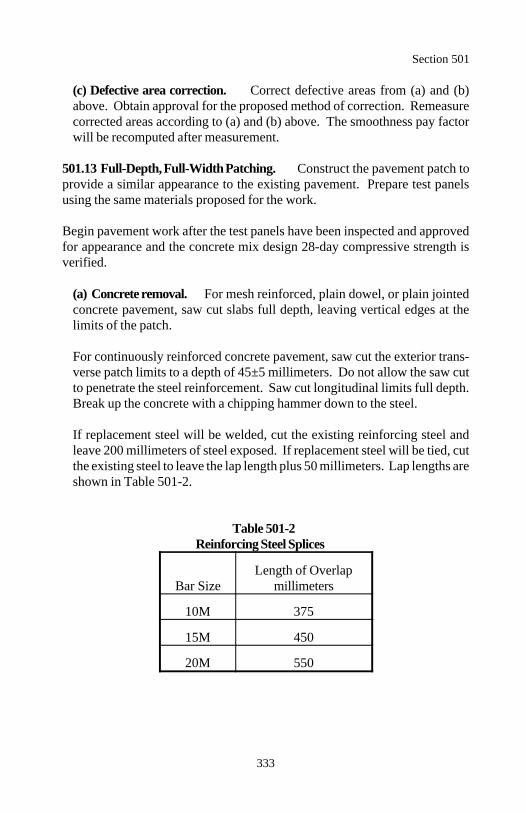
Section 501
333
(c) Defective area correction. Correct defective areas from (a) and (b)above. Obtain approval for the proposed method of correction. Remeasurecorrected areas according to (a) and (b) above. The smoothness pay factorwill be recomputed after measurement.
501.13 Full-Depth, Full-Width Patching. Construct the pavement patch toprovide a similar appearance to the existing pavement. Prepare test panelsusing the same materials proposed for the work.
Begin pavement work after the test panels have been inspected and approvedfor appearance and the concrete mix design 28-day compressive strength isverified.
(a) Concrete removal. For mesh reinforced, plain dowel, or plain jointedconcrete pavement, saw cut slabs full depth, leaving vertical edges at thelimits of the patch.
For continuously reinforced concrete pavement, saw cut the exterior trans-verse patch limits to a depth of 45±5 millimeters. Do not allow the saw cutto penetrate the steel reinforcement. Saw cut longitudinal limits full depth.Break up the concrete with a chipping hammer down to the steel.
If replacement steel will be welded, cut the existing reinforcing steel andleave 200 millimeters of steel exposed. If replacement steel will be tied, cutthe existing steel to leave the lap length plus 50 millimeters. Lap lengths areshown in Table 501-2.
Table 501-2Reinforcing Steel Splices
Bar Size millimetersLength of Overlap
10M 375
15M 450
20M 550
Section 501
334
Remove the concrete by either or both of the following methods:
(1) Break-up and clean-out method. Break up the concrete from thecenter of the patch area toward the end saw cuts. Remove the concretepieces with equipment that will not damage the underlying surface.
(2) Lift-out method. Lift the slab in one or more pieces without disturb-ing the underlying surface. Clean out the area with hand tools.
Dispose of the concrete according to Section 203. When directed, excavatethe underlying material to a maximum depth of 300 millimeters and replacewith aggregate base according to Sections 204 and 301. Prevent adjacentconcrete slabs from being undermined.
Remove and replace adjacent slabs damaged by concrete removal. Repairspalls using partial depth patching methods according to Section 502.
Repair all saw overcuts at the corner of repair areas and nicks to adjacentpavement outside the perimeter of the repair area with non-corrosive, non--shrink grout.
(b) Replacing reinforcing steel. For continuously reinforced concretepavement, if more than 10 percent of the reinforcing steel is visibly corrodedor damaged, extend the limits of the patch over the required lap length. Therequired lap lengths for various sizes of reinforcing steel bars are shown inTable 501-2.
For concrete pavement patches, provide a 75-millimeter clearance betweenthe ends of new reinforcing steel and the existing slab face. Match the num-ber, type, and spacing of the new reinforcement to the existing pavement.Support reinforcing steel with bar chairs or other approved methods whileplacing concrete.
(c) Joints. Construct joints according to Subsection 501.08. Field adjustlocations and lengths of joints as directed at intersections, median openings,and other areas of odd shaped slabs such that no joint is less than 460 milli-meters long and no slab has an angle less than 60 degrees. Construct jointsperpendicular to the edge of pavement.
Section 501
335
Place dowels or tie bars into the existing slab. Drill the dowel or tie barholes into the face at the required diameter with the drill rigidly supported.Completely fill the holes around the dowels and tie bars with an epoxy ornonshrink grout for a permanent fastening to the existing concrete. Furnisha plug or donut to prevent epoxy or grout loss.
Edge all transverse and longitudinal joints against forms or existing pave-ment. Transverse joints in a continuous lane pour or longitudinal joints in acontinuous dual lane pour do not require edging.
Clean the exposed faces of joints according to Subsection 502.06(a). Sealjoints according to Subsection 501.11.
(d) Concrete placement. Construct side forms to overlap the ends of theexisting slab. Securely fasten side forms so they do not move when concreteis placed. To accommodate forms for the patch, excavate the adjacent shoul-ders a maximum width of 300 millimeters.
Cast each patch in one continuous full-depth operation. After removal of theforms, backfill, compact, and return the excavated shoulder area to its previ-ous condition.
(e) Finishing. Finish patches according to Subsection 501.09 to match theplane and texture of the contiguous pavement.
501.14 Opening to Traffic. Do not allow traffic on new concrete pavementearlier than 14 days after concrete placement, unless concrete tests indicate oneof the following conditions is obtained.
(a) Flexural strength of 4 megapascals according to AASHTO T 97(b) Compressive strength of 25 megapascals according to AASHTO T 22
Cure specimens according to AASHTO T 23, Curing, Curing for DeterminingForm Removal Time or When a Structure May be Put into Service.
Do not allow traffic on the pavement when joint sealant is tacky and trafficdebris would imbed into the sealant.
Section 501
336
501.15 Acceptance. Material (except reinforcing steel) for portland cementconcrete pavement will be evaluated under Subsections 106.02 and 106.03.Furnish a production certification for the portland cement.
The concrete mixture's slump, air content, unit mass, and temperature will beevaluated under Subsections 106.02 and 106.04. See Table 501-3 for mini-mum sampling and testing.
Concrete compressive strength, pavement thickness, and pavement smoothnesswill be evaluated under Subsection 106.05. See Table 501-3 for minimumsampling and testing.
(a) Compressive strength. The lower specification limit is the minimumrequired compressive strength at 28 days (f ) specified in Table 501-1. Ac
single compressive strength test result is the average result from 2 cylinderscast from the same load and tested at 28 days. See Table 501-3 for theacceptance quality characteristic category.
(b) Pavement thickness. The lower specification limit is the required thick-ness minus 6 millimeters. See Table 501-3 for the acceptance quality charac-teristic category.
(c) Pavement smoothness. See Subsection 501.12. A sublot is a 0.1-kilo-meter section of traveled way and a lot is the surface of the entire project.The upper specification limit is 80 millimeters per kilometer. See Table 501-3 for the acceptance quality characteristic category.
Construction (including batching, placing, finishing, and curing concrete) ofthe portland cement concrete pavement will be evaluated under Subsections106.02 and 106.04.
Reinforcing steel will be evaluated under Section 554.
Section 501
337
Measurement
501.16 Measure portland cement concrete pavement by the square meter.Measure square meter width horizontally including allowable curve widening.Measure the square meter length horizontally along the centerline of the road-way.
Measure sealing joints under Section 502.
Measure removal and disposal of unsuitable material in the subbase or sub-grade under Section 204.
Measure patching and leveling material used to replace unsuitable materialremoved from the roadbed under the applicable Sections.
Payment
501.17 The accepted quantities, measured as provided above, will be paid atthe contract price per unit of measurement for the pay items listed below thatare shown in the bid schedule except the portland cement concrete pavementcontract unit bid price will be adjusted according to Subsection 106.05. Pay-ment will be full compensation for the work prescribed in this Section. SeeSubsection 109.05.
Payment for portland cement concrete pavement will be made at a price deter-mined by multiplying the contract unit bid price by the material pay factor.The material pay factor is the lowest single pay factor determined for eithercompressive strength or pavement thickness.
Section 501
338
In addition, a separate adjustment will be made for pavement smoothnessaccording to the following formula:
A = 12 000(PF - 1.00)(L)
Where:
A = Adjustment to contract payment in dollars for pavement smooth-ness.
L = Total project length in lane kilometers of traveled way. Measureproject length to 3 decimal places.
PF = Pay factor for smoothness with respect to the upper specificationlimit determined according to Subsection 106.05 after completionof corrective work.
Payment will be made under:
Pay Item Pay Unit
50101 Reinforced portland cement concrete pavement, Square meter___ millimeter depth
50102 Plain portland cement concrete pavement, Square meter ___ millimeter depth
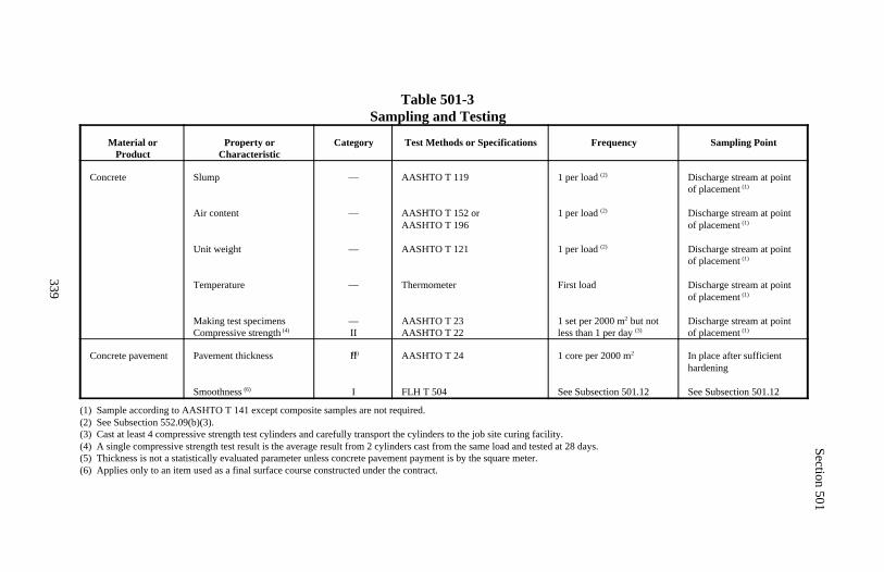
Section 501
339
Table 501-3Sampling and Testing
Material orProduct
Property orCharacteristic
Category Test Methods or Specifications Frequency Sampling Point
Concrete Slump
Air content
Unit weight
Temperature
Making test specimensCompressive strength (4)
—
—
—
—
—II
AASHTO T 119
AASHTO T 152 orAASHTO T 196
AASHTO T 121
Thermometer
AASHTO T 23AASHTO T 22
1 per load (2)
1 per load (2)
1 per load (2)
First load
1 set per 2000 m but not2
less than 1 per day (3)
Discharge stream at pointof placement (1)
Discharge stream at pointof placement (1)
Discharge stream at pointof placement (1)
Discharge stream at pointof placement (1)
Discharge stream at pointof placement (1)
Concrete pavement Pavement thickness (5)
Smoothness (6)
II
I
AASHTO T 24
FLH T 504
1 core per 2000 m2
See Subsection 501.12
In place after sufficienthardening
See Subsection 501.12
(1) Sample according to AASHTO T 141 except composite samples are not required.(2) See Subsection 552.09(b)(3).(3) Cast at least 4 compressive strength test cylinders and carefully transport the cylinders to the job site curing facility.(4) A single compressive strength test result is the average result from 2 cylinders cast from the same load and tested at 28 days.(5) Thickness is not a statistically evaluated parameter unless concrete pavement payment is by the square meter.(6) Applies only to an item used as a final surface course constructed under the contract.
340
Section 502.) PORTLAND CEMENTCONCRETE PAVEMENT RESTORATION
Description
502.01 This work consists of the restoration of portland cement concretepavement. This work includes partial depth patching, pavement jacking, sub-sealing, surface grinding, crack and joint repair, and breaking and seatingbefore a pavement overlay.
Material
502.02 Conform to the following Section and Subsections:
Epoxy resin adhesives 725.21Joint fillers and sealants 712.01Polymer grout, mortar, and concrete 725.22Portland cement concrete pavement 501Water 725.01
Construction Requirements
502.03 Composition of Mix (Concrete Mix Design). Design the concretemix according to Subsection 501.03. Provide cement which is similar in colorto that used in existing pavement. Provide aggregates which are similar ingradation, color, and hardness to those used in existing pavement.
Design a hydraulic cement grout mix according to Subsection 725.22.
502.04 Equipment. Furnish equipment conforming to Section 501 and thefollowing:
(a) Portland cement concrete pavement removal. Furnish removal equi-pment that will not fracture the concrete below the necessary patch depth.
(b) Routing. Furnish routers which will control and maintain the requiredcutting depth and width, without damaging the adjacent concrete or remain-ing joint material.
Section 502
341
(c) Sandblasting. Furnish sandblasting equipment that will remove anyresidual sealant, oil, or other foreign material in joints that may prevent bondof new sealant.
(d) Jet waterblasting. Furnish a high-pressure water jet machine that iscapable of removing all residual sealant, oil, or other foreign material injoints that may prevent the new sealant from bonding.
(e) Air compressors. Furnish air compressors with a minimum nozzle pres-sure of 690 kilopascals and capable of dislodging loose debris and dryingjoints and cracks.
(f) Joint and crack sealing. Furnish sealing equipment according to themanufacturer's recommendations for the sealing material furnished.
(g) Grouting. Furnish a grout plant which consists of a positive displace-ment cement injection pump and a high-speed colloidal mill. Operate colloi-dal mixing machine at speeds necessary to make a homogeneous mixture.
Furnish an injection pump having a pressure capability of 1900±170 kilopas-cals when pumping a grout slurry mixed to a 12-second flow cone time andthat will continuously pump at a minimum rate of 6.0 liters per minute. Thesystem may be modified by adding a recirculating hose and valve at thedischarge end of the pump.
Batch water through a meter or scale capable of measuring the total day'sconsumption. Furnish hoses, fittings, and control which provide a positiveseal during grout injection.
(h) Drilling. Furnish rock drills capable of drilling straight and true mini-mum 38-millimeter holes through the concrete slab, steel reinforcement, andbase material.
Furnish rock drills weighing less than 27 kilograms that are capable of drill-ing with a downward pressure of less than 90 kilograms. Furnish an augerto open clogged holes and existing pavement jacking holes.
Section 502
342
(i) Slab stabilization testing. Furnish testing equipment including the fol-lowing:
(1) A 2-axle truck with dual rear wheels. Load the rear axle to 80 kilo-newtons evenly distributed between the 2 wheel paths. (2) Static load measuring gauges consisting of 4 gauges on 2 gauge mounts, 2 gauges per mount, capable of detecting slab movement underload.(3) A modified Benkelman beam, or similar approved device.
(j) Surface diamond grinding. Furnish power driven, self-propelled grind-ing equipment, specifically designed to smooth and texture portland cementconcrete pavement with diamond blades. Furnish equipment that will doeach of the following:
(1) Cut or plane at least 1 meter in width.(2) Not encroach on traffic movement outside of the work area.(3) Grind the surface without spalling at joints and cracks or fracturingsurface aggregates.
(k) Fracturing and seating. Furnish an approved fracturing device capableof producing the desired fracturing pattern without displacing or spalling thepavement. "Headache balls" and vibratory pneumatic hammers will not bepermitted.
Furnish at least a 32-metric ton pneumatic tired roller to seat the brokenpavement. Towing equipment shall have pneumatic tires and shall move theroller forward and backward along predetermined lines.
502.05 Partial Depth Patching. This work consists of patching spalls, pot-holes, corner breaks, or other surface distresses in portland cement concretepavement.
Construct the pavement patch similar in appearance to the existing pavement.Prepare test panels using the same material proposed for the work. Beginconcrete pavement work after approval of the concrete mix design and the testpanel appearance.
(a) Patch material. Use an epoxy mortar or polymer concrete patch mate-rial for patches less than or equal to 40 millimeters deep. Use portland ce-ment concrete for patches greater than 40 millimeters deep.
Section 502
343
(b) Patch area preparation. Extend the limits of repair areas a minimumof 100 millimeters outside the area of delamination. Saw cut the perimeterof the patch area, parallel to the existing joint, to a minimum depth of 40millimeters and provide a vertical face at the edge of the patch. Near verticaledges from milling or grinding machines are acceptable. Repair all saw over-cuts at corners of repair areas and nicks to adjacent pavement outside theperimeter of the repair area with noncorrosive, nonshrink grout.
Break out concrete within the patch area to a minimum depth of 40 milli-meters to expose sound and clean concrete. If the depth of the repair exceeds100 millimeters, remove and replace the repair area as a full-width, full-depthslab according to Subsection 501.13.
Sandblast exposed concrete faces clean of loose particles, oil, dust, traces ofasphalt concrete, and other contaminants before patching. Remove sand-blasting residue immediately before placing the epoxy resin adhesive. Remove shoulders adjacent to the patch longitudinally to the depth of thepatch and to a maximum width of 300 millimeters, to facilitate placing formwork. Patch and compact shoulders with material similar to the existingshoulder. Dispose of the concrete according to Section 203.
(c) Placing patch material. Apply an epoxy resin adhesive according to themanufacturer's recommendations. Delay concrete placement until the epoxybecomes tacky. Place and consolidate the patch mixture to eliminate voidsat the interface of the patch and existing concrete. Finish patches accordingto Subsection 501.09 to match the plane and texture of the contiguous pave-ment. Cure according to Subsection 501.10.
(d) Joints. If a partial depth repair area abuts a working joint, repair thejoint similar to the existing to maintain a working joint. Form a new joint tothe same width as the existing joint. Seal the joint according to Subsection502.06.
Section 502
344
502.06 Joint and Crack Repair. This work consists of repairing and reseal-ing joints and cracks in existing concrete pavement.
(a) Preparation of joints and cracks. Clean and reseal longitudinal andtransverse joints as required. Remove the existing material in the joints andclean the joint no earlier than 1 day before resealing. Use procedures thatwill not damage joints or previously repaired patches.
Remove sealant with a router to a minimum depth of 2.5 times the joint widthto accommodate the backer rod and to provide the required depth for the newsealant. After routing, clean the adjacent pavement surfaces.
Reface cracks with a concrete saw. Remove old sealant from the crack facesto expose new, clean concrete. When the crack widths vary and the crackfaces are ravelled and irregular, cut a crack reservoir depth of 20 millimeters.
Thoroughly clean the joint or crack of all foreign material. Clean the jointby sandblasting, high-pressure water jet, or with a mechanical wire brush.Repeat the process until a new, clean concrete face is exposed. Dry the jointwith compressed air.
Use sawing if other methods will not properly clean the joint. Limit sawingto exposing clean, new, concrete faces in the joint with a minimum allowablecut of 2 millimeters on each face of the joint.
(b) Backer rod. Install the backer rod to the required depth after the jointsand cracks are clean and dry. Do not stretch or twist the backer rod duringinstallation. Limit the length of backer rod installed to that which can besealed during the same workday.
(c) Sealant application. Seal joints and cracks immediately after placing thebacker rod. Apply sealant at the air and surface temperatures recommendedby the sealant manufacturer. If the joint or crack becomes contaminated ordamp, remove the backer rod, clean and dry the joint or crack, and reinstalla new backer rod before placing the sealant. Immediately after application,tool the sealant to provide firm contact with the joint faces and to form therequired recess below the slab surface.
Section 502
345
502.07 Pavement Jacking. This work consists of raising and supporting theconcrete pavement to the specified grade tolerances by drilling and injectinghydraulic cement grout.
(a) Drilling holes. Determine a pattern for grout injection holes and submitfor approval. Drill holes vertically, round, and less than 50 millimeters indiameter. Prevent breaking out the bottom of the pavement.
(b) Jacking. Establish string lines from the pavement high points to monitorslab movement. Lower an expanding rubber packer or hose, providing apositive seal and connected to the discharge hose on the grout plant, into theholes. Do not allow the discharge end of the packer or hose to extend belowthe lower surface of the concrete pavement.
When jacking continuously reinforced concrete pavement, allow pumping toraise the pavement to within 3 millimeters of the string line grade. Whenjacking jointed pavement and bridge approach slabs, allow pumping to raisethe pavement to within 6 millimeters of the transverse and longitudinalgrades.
Continuous pressures to 1.4 megapascals are permitted. Use pressures to 2megapascals only for short periods (30 seconds or less). If the pavement isbonded to the subbase, brief pressure rises (10 seconds or less) to 4.1 mega-pascals may be allowed. Stop pumping if grout extrudes through cracks,joints, shoulders, or from back pressure in the hose.
(c) Overjacking. Grind pavement raised above the specified tolerances tograde. If the overjacking is greater than 25 millimeters, remove and replacethe pavement or a portion thereof, according to Subsection 501.13.
(d) Cracks. New cracks radiating through the grout injection holes arepresumed to have been caused by improper injection techniques. If anycracks emanate from any grout injection hole, remove and replace the slabor a portion of the slab according to Subsection 501.13.
(e) Hole patching. After the grout has set and the hole plugs are removed,remove all grout from the holes for the full depth of the slab, and fill theholes with an epoxy mortar. Repair damaged holes.
Section 502
346
502.08 Undersealing and Slab Stabilization. This work consists ofpumping a hydraulic cement grout mixture through holes drilled in the pave-ment into voids underneath the slabs to stabilize and underseal concrete pave-ment.
(a) Preliminary testing. Perform all testing at night or when there is noevidence of slab lock-up due to thermal expansion. Testing may be allowedto continue if the slabs are not interlocked or under compression. Furnishtesting equipment as provided in Subsection 502.04(i).
Test each designated slab using a static method as follows:
(1) Position one set of gauges with one gauge referenced to the corner ofeach slab on both sides of the joint near the pavement edge.
(2) Set the gauges to zero with no load on the slab on either side of thejoint.
(3) Move the test truck into position and stop with the center of the testaxle 300 millimeters behind the joint and the outside test wheel 300 milli-meters from the pavement edge. Read the back gauge.
(4) Move the test truck across the joint to a similar position 300 milli-meters forward from the joint and stop. Read the forward gauge.
(5) Repeat for each joint to be tested. Underseal all slabs with a deflec-tion of more than 0.8 millimeter.
(b) Drilling Holes. Drill holes using the required hole pattern. An alteredhole pattern may be approved based on slab testing and field conditions.Size drilled holes to provide a positive seal for the pumping nozzle. For thefirst undersealing, drill holes to a depth of 75 millimeters beneath the bottomof the concrete.
Submit the number, depth, and location of holes for the second undersealingfor review and approval.
Section 502
347
(c) Cleaning holes. After the holes are drilled and before pumping theunderseal grout, clean the hole with compressed air to remove debris andprovide a passage for the grout.
(d) Pumping underseal grout. Pump grout in all holes. Seal the nozzle ofthe discharge hose in the hole to maintain the grout pressure underneath theslab. Do not allow the nozzle end to extend below the bottom of the con-crete.
Continue pumping into a hole until grout flows out other holes, joints, orcracks, or until the slab begins to lift. Stop grouting if there is any lift in theslab or the adjacent shoulder.
During pumping and grouting, closely monitor lift measuring devices toprevent pumping pressures greater than 700 kilopascals and slab lift greaterthan 1.3 millimeters total accumulative movement measured at the outsidejoint corner. Do not plug holes while grouting.
Prevent the slab from cracking or breaking. Remove and replace damagedslabs according to Subsection 501.13.
(e) Permanently sealing holes. After the grout has set, remove all groutfrom the holes for the full depth of the slab and fill the holes with a non-shrink grout or epoxy mortar. Repair damaged holes.
(f) Stability testing. After the designated slabs have been undersealed andtested according to (a) above and after 24 hours have elapsed, underseal anyslab that continues to show excess movement. The CO may accept or directreplacement of any slab that continues to show movement in excess of thatspecified after undersealing twice. Remove and replace designated slabsaccording to Subsection 501.13.
502.09 Surface Diamond Grinding. This work consists of grinding existingconcrete pavement to eliminate joint or crack faults and providing positivelateral drainage. Uniformly transition auxiliary or ramp lane grinding from themainline edge to provide positive drainage and an acceptable riding surface.
Remove solid residue from pavement surfaces before it is blown by traffic orwind. Do not allow residue to flow across lanes used by public traffic or intodrainage facilities.
Section 502
348
Produce a surface texture consisting of parallel grooves 3±0.5 millimeterswide. Provide an area between the grooves 2.2±0.5 millimeters, and a differ-ence between the peaks of the ridges and the bottom of the grooves of approxi-mately 2 millimeters.
Test the ground pavement surfaces for pavement smoothness according toSubsection 501.12(b). Check transverse joints and random cracks with a 3-meter straightedge. Misalignment of surface planes on adjacent sides of thejoints or cracks and between each grinding pass shall be less than 1.6 millime-ters. The transverse slope of the pavement shall have no depressions or slopemisalignment greater than 6 millimeters in 3 meters tested perpendicular to thecenterline. Straightedge requirements do not apply across longitudinal jointsor outside of ground areas.
502.10 Fracturing Concrete Pavement. This work consists of fracturingexisting concrete pavement and firmly seating or compacting the pavementbefore a pavement overlay. Use one of the following methods:
(a) Crack and seat. Crack the existing concrete pavement into full-depthhairline cracks with pieces approximately 0.5 to 1.0 meters in size. Seat thepieces firmly into the foundation.
(b) Break and seat. Break the existing concrete pavement into full-depthhairline cracks with pieces approximately 0.4 to 0.6 meters in size. Rupturethe reinforcement or break the concrete bond and seat the pieces firmly intothe foundation.
(c) Rubblize and compact. Completely fracture the existing pavement intopieces approximately 0.05 to 0.15 meters in size. Remove exposed reinforc-ing steel and wire mesh. Compact the pieces into a layer.
The CO will designate a test section. Fracture the test section using varyingenergy and striking heights to establish a satisfactory evenly distributed crackpattern. Obtain 150-millimeter diameter pavement cores at 10 designatedlocations over the cracks to verify that the cracks are full depth.
When fracturing a test section, furnish and apply water to dampen the pave-ment following fracturing to enhance visual determination of the fracturingpattern. Furnish and apply water to a checked section at least once a day toverify that a satisfactory fracture pattern is maintained. If approved, adjust theenergy and/or striking height based on check sections.
Section 502
349
Seating consists of rolling the rigid pavement, 2 passes minimum with a 45-metric ton roller or 4 to 7 passes with a 32-metric ton roller, until the concretepieces are firmly seated. Compacting consists of rolling the rigid pavement,2 passes minimum with a 9-metric ton vibratory roller. The CO will determinethe maximum number of roller passes on the test section to assure seating orcompacting without damaging the pavement. Remove all loose pieces of bro-ken concrete that are not firmly seated.
Tack, according to Section 412, the near vertical sides where full-depth brokenconcrete is removed. Fill the hole with asphalt concrete according to Section402.
Prevent the formation of continuous longitudinal cracks. Do not fracture pave-ment within 3 meters of existing box or pipe culverts.
Fill 25-millimeter or greater depressions, resulting from the compaction, withgraded aggregate and recompact.
If unable to fracture pavement to the specified size due to poor subgrade, re-move the pavement and replace with aggregate according to Section 301. Clean and seal existing joints and cracks greater than 15 millimeters widthaccording to Subsection 414.05.
Place the first course of asphalt concrete within 48 hours following the fractur-ing operation. If the pavement is used to maintain traffic after fracturing, butbefore the asphalt concrete overlay, sweep and patch to maintain a safe ridingsurface.
502.11 Opening to Traffic. Do not allow traffic on patched pavement untilthe portland cement concrete has a compressive strength of 25 megapascalswhen tested according to AASHTO T 22 or until the grout used for jacking orundersealing the pavement has attained 4.2 megapascals when tested with a160-square millimeter probe according to AASHTO T 197.
Do not allow traffic on sealed joints when the sealant is tacky and traffic debrisembeds into the sealant.
Section 502
350
502.12 Acceptance. Material for portland cement concrete pavement restora-tion will be evaluated under Subsections 106.02 and 106.03. Furnish a produc-tion certification for the portland cement.
The concrete mixture's slump, air content, unit mass, and temperature will beevaluated under Subsections 106.02 and 106.04. See Table 502-1 for mini-mum sampling and testing.
The concrete compressive strength will be evaluated under Subsection106.04. The lower specification limit is the minimum required compressivestrength at 28 days (f ) specified in Table 501-1. A single compressivec
strength test result is the average result from two cylinders cast from the sameload and tested at 28 days. See Table 502-1 for minimum sampling and test-ing.
Construction (including batching, placing, finishing, and curing concrete) ofthe portland cement concrete will be evaluated under Subsections 106.02 and106.04.
Grout will be evaluated under Subsection 106.04. See Table 502-1 for mini-mum sampling and testing requirements.
Portland cement concrete pavement restoration work (including partial depthpatching, pavement jacking, subsealing, surface grinding, crack and joint re-pair, and breaking and seating) will be evaluated under Subsections 106.02 and106.04.
Measurement
502.13 Measure concrete pavement patch by the square meter for all repairswith an average depth between 40 and 100 millimeters.
Measure sealing joints and cracks by the meter along the alignment of the jointor crack.
Measure grout for pavement jacking and undersealing by the cubic meter at thepump.
Measure undersealing holes by the each.
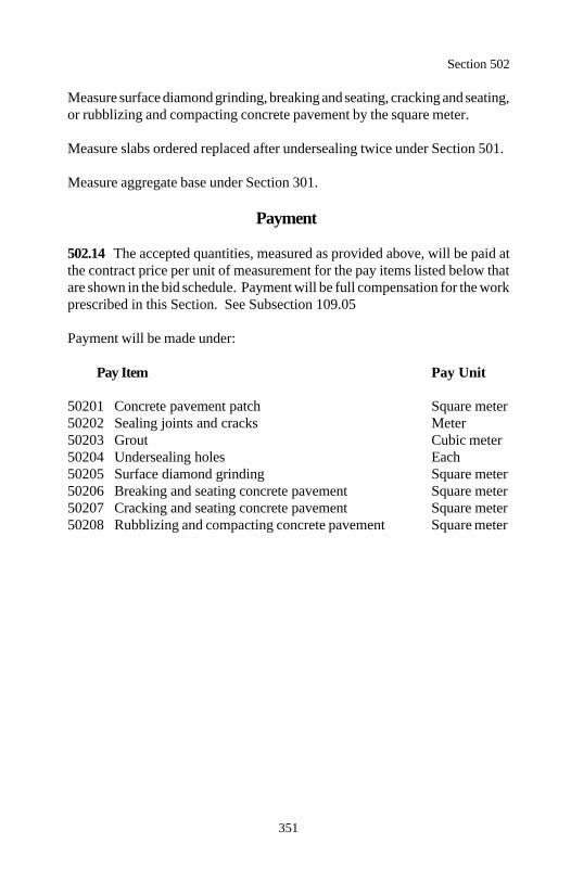
Section 502
351
Measure surface diamond grinding, breaking and seating, cracking and seating,or rubblizing and compacting concrete pavement by the square meter.
Measure slabs ordered replaced after undersealing twice under Section 501.
Measure aggregate base under Section 301.
Payment
502.14 The accepted quantities, measured as provided above, will be paid atthe contract price per unit of measurement for the pay items listed below thatare shown in the bid schedule. Payment will be full compensation for the workprescribed in this Section. See Subsection 109.05
Payment will be made under:
Pay Item Pay Unit
50201 Concrete pavement patch Square meter50202 Sealing joints and cracks Meter50203 Grout Cubic meter50204 Undersealing holes Each50205 Surface diamond grinding Square meter50206 Breaking and seating concrete pavement Square meter50207 Cracking and seating concrete pavement Square meter50208 Rubblizing and compacting concrete pavement Square meter
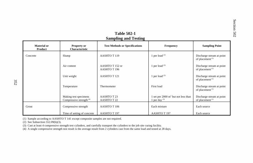
Section 502
352
Table 502-1Sampling and Testing
Material orProduct
Property orCharacteristic
Test Methods or Specifications Frequency Sampling Point
Concrete Slump
Air content
Unit weight
Temperature
Making test specimensCompressive strength (4)
AASHTO T 119
AASHTO T 152 orAASHTO T 196
AASHTO T 121
Thermometer
AASHTO T 23AASHTO T 22
1 per load (2)
1 per load (2)
1 per load (2)
First load
1 set per 2000 m but not less than2
1 per day (3)
Discharge stream at pointof placement (1)
Discharge stream at pointof placement (1)
Discharge stream at pointof placement (1)
Discharge stream at pointof placement (1)
Discharge stream at pointof placement (1)
Grout Compressive strength
Time of setting of concrete
AASHTO T 106
AASHTO T 197
Each mixture
AASHTO T 197
Each source
Each source
(1) Sample according to AASHTO T 141 except composite samples are not required.(2) See Subsection 552.09(b)(3).(3) Cast at least 4 compressive strength test cylinders, and carefully transport the cylinders to the job site curing facility.(4) A single compressive strength test result is the average result from 2 cylinders cast from the same load and tested at 28 days.

353
DIVISION 550Bridge Construction
354
Section 551.) DRIVEN PILES
Description
551.01 This work consists of furnishing and driving piles. This work alsoincludes furnishing and placing reinforcing steel and concrete in concrete-filledsteel shell and concrete-filled pipe piles.
Piles are designated as steel H-piles, concrete-filled steel shell piles, concrete-filled pipe piles, precast concrete piles, prestressed concrete piles, or timberpiles. Pile load tests are designated as static or dynamic.
Material
551.02 Conform to the following Sections and Subsections:
Concrete piles 715.03Paint 708Pile shoes 715.08Reinforcing steel 709.01Sheet piles 715.07Splices 715.09Steel H-piles 715.06Steel pipes 715.05Steel shells 715.04Structural concrete 552Treated timber piles 715.02Untreated timber piles 715.01
Construction Requirements
551.03 Pile Driving Equipment. Furnish equipment meeting the followingrequirements.
(a) Pile hammers.
(1) Gravity hammers. Gravity hammers can only be used to drive timberpiles. Furnish a hammer with a ram weighing between 900 and 1600 kilo-grams and limit the drop height to 4.5 meters. The ram mass shall begreater than the combined mass of the drive head and pile. Provide ham-mer guides to ensure concentric impact on the drive head.
Section 551
355
(2) Open-end diesel hammers. Equip open-end (single acting) dieselhammers with a device, such as rings on the ram or a scale (jump stick)extending above the ram cylinder, to permit visual determination of ham-mer stroke. Submit a chart from the hammer manufacturer equatingstroke and blows per minute for the hammer to be used. A speed versusstroke calibration may be used if approved.
(3) Closed-end diesel hammers . Submit a chart, calibrated to actualhammer performance within 90 days of use, equating bounce chamberpressure to either equivalent energy or stroke for the hammer to be used.Equip hammers with a dial gauge for measuring pressure in the bouncechamber. Make the gauge readable from ground level. Calibrate the dialgauge to allow for losses in the gauge hose. Verify the accuracy of thecalibrated dial gauge during driving operations by ensuring that cylinderlift occurs when bounce chamber pressure is consistent with the maximumenergy given in the hammer specifications. Do not use closed-end dieselhammers that do not attain cylinder lift at the maximum energy-bouncechamber pressure relationship given in the hammer specification.
(4) Air or steam hammers . Furnish plant and equipment for steam andair hammers with sufficient capacity to maintain the volume and pressurespecified by the hammer manufacturer. Equip the hammer with accuratepressure gauges that are easily accessible. Use a hammer with the massof the striking parts equal to or greater than one third the combined massof the driving head and pile. The combined mass shall be at least 1250kilograms.
Measure inlet pressures for double-acting and differential-acting air orstream hammers with a needle gauge at the head of the hammer whendriving test piles. If required, also measure inlet pressures when drivingproduction piles. A pressure versus speed calibration may be developedfor specific driving conditions at the project as an alternative to periodicmeasurements with a needle gauge.
(5) Nonimpact hammers. Do not use nonimpact hammers, such as vi-bratory hammers, unless permitted in writing or when specified in thecontract. If permitted, use such equipment for installing production pilesonly after the pile tip elevation or embedment length for safe support ofthe pile load is established by static or dynamic load testing. Control theinstallation of production piles when using vibratory hammers bypower consumption, rate of penetration, specified tip elevation, or otheracceptable methods that will ensure the required pile load capacity is
Section 551
356
obtained. On one out of every 10 piles driven, strike with an impact ham-mer of suitable energy to verify the required pile capacity is obtained.
(b) Approval of pile driving equipment. Furnish pile driving equipmentof such size that the permanent piles can be driven with reasonable effort tothe required lengths without damage.
The Government will evaluate the suitability of the equipment and will ac-cept or reject the driving system within 14 days of receipt of the pile anddriving equipment information. Approval of pile driving equipment will bebased on a wave equation analysis when dynamic load testing is required,when ultimate pile capacities exceed 2400 kilonewtons, or when precast orprestressed concrete piles are used. When the wave equation analysis is notused, approval of the pile driving equipment will be based on minimumhammer energy in Table 551-1. Approval of a pile hammer relative to driv-ing stress damage does not relieve the Contractor of responsibility for dam-aged piles.
Approval of the pile driving system is specific to the equipment data submit-ted. If the proposed equipment is modified or replaced, resubmit the reviseddata for approval before using. The revised driving system will be acceptedor rejected within 14 days of receipt of the revised pile, equipment, and waveequation analysis (if required) information. Use only the approved equip-ment during pile driving operations.
(1) Equipment submittal. Submit the following pile driving equipmentinformation at least 30 days before driving piles. When dynamic loadtests are required by the contract, submit a wave equation analysis per-formed by a pile specialty consultant meeting the requirements of Subsec-tion 551.11. If dynamic load testing is not required by the contract, theGovernment will perform the wave equation analysis.
(a) General. Project and structure identification, pile driving contrac-tor or subcontractor, and auxiliary methods of installation such asjetting or preboring and the type and use of the equipment.
(b) Hammer. Manufacturer, model, type, serial number, rated energy( _____ at _____ length of stroke), and modifications.
(c) Capblock (hammer cushion). Material, thickness, area, modulusof elasticity (E), and coefficient of restitution (e).
Section 551
357
(d) Pile cap. Helmet mass, bonnet mass, anvil block mass, and drive-head mass.
(e) Pile cushion. Material, thickness, area, modulus of elasticity (E),and coefficient of restitution (e).
(f) Pile. Pile type, length (in leads), mass per meter, wall thickness,taper, cross-sectional area, design pile capacity, description of splice,and tip treatment description.
(2) Wave equation. The required number of hammer blows indicated bythe wave equation at the ultimate pile capacity shall be between 3 and 15per 25 millimeters. In addition, the pile stresses resulting from the waveequation analysis shall not exceed the values at which pile damage isimpending. The point of impending damage is defined for steel, concrete,and timber piles as follows.
(a) Steel piles. Limit the compressive driving stress to 90 percent ofthe yield stress of the pile material.
(b) Concrete piles. Limit the tensile (TS) and compressive (CS) driv-ing stresses to:
TS 3f + EPV c1/2
CS 0.85f - EPVc
Where:
f = The 28-day design compressive strength of the concretec
EPV = The effective prestress value
(c) Timber piles. Limit the compressive driving stress to 3 times theallowable static design stress.
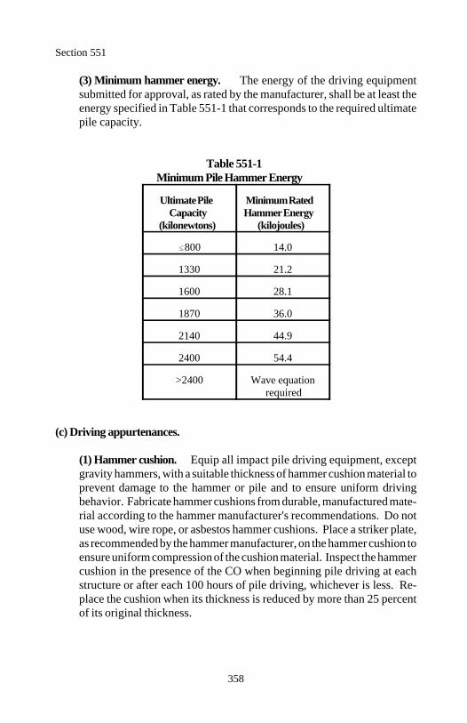
Section 551
358
(3) Minimum hammer energy. The energy of the driving equipmentsubmitted for approval, as rated by the manufacturer, shall be at least theenergy specified in Table 551-1 that corresponds to the required ultimatepile capacity.
Table 551-1Minimum Pile Hammer Energy
Ultimate Pile Minimum RatedCapacity Hammer Energy
(kilonewtons) (kilojoules)
800 14.0
1330 21.2
1600 28.1
1870 36.0
2140 44.9
2400 54.4
>2400 Wave equation required
(c) Driving appurtenances.
(1) Hammer cushion. Equip all impact pile driving equipment, exceptgravity hammers, with a suitable thickness of hammer cushion material toprevent damage to the hammer or pile and to ensure uniform drivingbehavior. Fabricate hammer cushions from durable, manufactured mate-rial according to the hammer manufacturer's recommendations. Do notuse wood, wire rope, or asbestos hammer cushions. Place a striker plate,as recommended by the hammer manufacturer, on the hammer cushion toensure uniform compression of the cushion material. Inspect the hammercushion in the presence of the CO when beginning pile driving at eachstructure or after each 100 hours of pile driving, whichever is less. Re-place the cushion when its thickness is reduced by more than 25 percentof its original thickness.
Section 551
359
(2) Pile drive head. Provide adequate drive heads for impact hammersand provide appropriate drive heads, mandrels, or other devices for spe-cial piles according to the manufacturer's recommendations. Align thedrive head axially with the hammer and pile. Fit the drive head aroundthe pile head so that it will prevent transfer of torsional forces duringdriving while maintaining proper alignment of hammer and pile.
(3) Leads. Support piles in line and position with leads while driving.Construct pile driver leads to allow freedom of movement of the hammerwhile maintaining axial alignment of the hammer and the pile. Do not useswinging leads unless permitted in writing or specified in the contract.When swinging leads are permitted, fit swinging leads with a pile gate atthe bottom of the leads and, in the case of battered piles, with a horizontalbrace between the crane and the leads. Adequately embed leads in theground or constrain the pile in a structural frame (template) to maintainproper alignment. Provide leads of sufficient length that do not requirea follower but will permit proper alignment of battered piles.
(4) Followers. Followers are not permitted unless approved in writing.When followers are permitted, drive the first pile in each bent or substruc-ture unit and every tenth pile thereafter, full length without a follower, toverify that adequate pile embedment is being attained to develop therequired ultimate capacity. Provide a follower of such material and di-mensions that will permit the piles to be driven to the required penetra-tion. Hold and maintain follower and pile in proper alignment duringdriving.
(5) Jetting. Do not use jetting unless approved in writing. Provide jet-ting equipment with sufficient capacity to deliver a consistent pressureequivalent to at least 700 kilopascals at two 20-millimeter jet nozzles. Jetso as not to affect the lateral stability of the final inplace pile. Remove jetpipes when the pile tip is at least 1.5 meters above the prescribed tipelevation and drive the pile to the required ultimate capacity with an im-pact hammer. Control, treat if necessary, and dispose of all jet water inan approved manner.
Section 551
360
551.04 Pile Lengths. Furnish piles with sufficient length to obtain the re-quired penetration and to extend into the pile cap or footing as indicated on theplans. In addition, increase the length to provide fresh heading and to providefor the Contractor's method of operation. When test piles are required, furnishpiles in the lengths determined by the test piles.
551.05 Test Piles. Install test piles when specified in the contract. Excavatethe ground at the site of each test pile or production pile to the elevation of thebottom of the footing before the pile is driven. Furnish test piles longer thanthe estimated length of production piles. Drive test piles with the same equip-ment as the production piles.
Drive test piles to the required ultimate capacity at the estimated tip elevation.Allow test piles that do not attain the required ultimate capacity at the esti-mated tip elevation to "set up" for 24 hours before re-driving. Warm the ham-mer before re-driving begins by applying at least 20 blows to another pile. Ifthe required ultimate capacity is not attained on re-driving, drive a portion orall of the remaining test pile length and repeat the "set up" and re-drive proce-dure as directed. Splice and continue driving until the required ultimate pilecapacity is obtained.
Test piles to be used in the completed structure shall conform to the require-ments for production piles. Remove test piles not incorporated in the com-pleted structure to at least 0.5 meter below finished grade.
551.06 Driven Pile Capacity. Drive piles to the specified penetration and tothe depth necessary to obtain the required ultimate pile capacity. Splice pilesnot obtaining the required ultimate capacity at the ordered length and drivewith an impact hammer until the required ultimate pile capacity is achieved.
Use the dynamic formula to determine ultimate pile capacity of the inplace pileunless the wave equation is required according to Subsection 551.03(b).
(a) Wave equation. Adequate penetration will be considered to be obtainedwhen the specified wave equation resistance criteria is achieved within 1.5meters of the designated tip elevation. Drive piles that do not achieve thespecified resistance within these limits to a penetration determined by theCO.
Ru (7 E log(10N)) 550
N 10x
x Ru 550
7 E1
Section 551
361
(b) Dynamic formula . Drive the piles to a penetration necessary to obtainthe ultimate pile capacity according to the following formula:
Where:
Ru = Ultimate pile capacity in kilonewtonsE = Manufacturer's rated hammer energy in joules at the ram
stroke observed or measured in the fieldlog(10N) = logarithm to the base 10 of the quantity 10 multiplied by
NN = Number of hammer blows per 25 millimeters at final
penetration
Solving for N:
Factor of safety = 3.0
(1) Jetted piles. Determine the inplace ultimate capacity of jetted pilesbased on impact hammer blow counts (dynamic formula) after the jetpipes have been removed. After the pile penetration length necessary toproduce the required ultimate pile capacity has been determined by im-pact hammer blow count, install the remaining piles in each group or ineach substructure unit to similar depths with similar methods. Confirmthe required ultimate pile capacity has been achieved by using the dy-namic formula.
(2) Conditions for dynamic formula. The dynamic formula is appli-cable only if all of the following apply:
(a) The hammer is in good condition and operating in a satisfactorymanner.(b) The hammer ram falls freely.(c) A follower is not used.(d) The head of the pile is not broomed or crushed.
Section 551
362
551.07 Preboring. Prebore holes to natural ground when piles are driventhrough compacted embankments more than 1.5 meters in depth. Use auger-ing, wet rotary drilling, or other approved methods of preboring. Except forpiles end-bearing on rock or hardpan, stop preboring at least 1.5 meters abovethe estimated pile tip elevation and drive the pile with an impact hammer to apenetration which achieves the required ultimate pile capacity. Preboring mayextend to the surface of the rock or hardpan where piles are to be end-bearingon rock or hardpan. Seat the piles into the end-bearing strata.
Prebore holes smaller than the diameter or diagonal of the pile cross-sectionwhile allowing penetration of the pile to the specified depth. If subsurfaceobstructions such as boulders or rock layers are encountered, the hole diametermay be increased to the least dimension adequate for pile installation. Fill anyvoid space remaining around the pile after completion of driving with sand orother approved material. Do not use a punch or a spud in lieu of preboring.
Do not impair the capacity of existing piles or the safety or condition of adja-cent structures. If preboring disturbs the capacity of previously installed pilesor structures, restore the required ultimate capacity of piles and structures byapproved methods.
551.08 Preparation and Driving. Perform the work under Section 208.Make the heads of all piles plane and perpendicular to the longitudinal axis ofthe pile. Coordinate pile driving so as not to damage other parts of the com-pleted work.
Drive piles to within 50 millimeters of plan location at cutoff elevation for bentcaps and within 150 millimeters of plan location for piles capped below fin-ished ground. The pile shall not be closer than 100 millimeters to any cap face.Drive piles so that the axial alignment is within 20 millimeters per meter of therequired alignment. The CO may stop driving to check the pile alignment.Check alignment of piles that cannot be internally inspected after installationbefore the last 1.5 meters are driven. Do not pull laterally on piles or splice tocorrect misalignment. Do not splice a properly aligned section on a misalignedpile.
Place individual piles in pile groups either starting from the center of the groupand proceeding outward in both directions or starting at the outside row andproceeding progressively across the group.
Correct all piles driven improperly, driven out of proper location, misaligned,or driven below the designated cutoff elevation in an approved manner. Re-
Section 551
363
place piles damaged during handling or driving. Obtain approval for the pro-posed method(s) of correcting or repairing deficiencies.
(a) Timber piles. Do not use piles with checks wider than 15 millimeters.Drive treated timber piles within 6 months after treatment. Handle and carefor pressure-treated piles according to AWPA Standard M 4.
Carefully shape the pile tip to secure an even uniform bearing for the pileshoe. Fasten the shoe securely to the pile. Treat all holes, cuts, or caps intreated piles with 2-brush applications of creosote-coal tar solution.
(b) Steel piles. Furnish full-length, unspliced piles for lengths up to 18meters. If splices are required in the first pile driven and it is anticipated thatsubsequent piles will also require splices, place the splices in lower third ofthe pile. Splice lengths less than 3 meters are not permitted and only 2splices per pile are allowed.
Load, transport, unload, store, and handle steel piles so the metal is keptclean and free from damage. Do not use piles that exceed the camber andsweep permitted by allowable mill tolerance. Steel piles damaged duringinstallation are considered unsatisfactory unless the bearing capacity isproven to be 100 percent of the required ultimate capacity by load tests.Load tests performed will be at no cost to the Government.
(c) Precast and prestressed concrete piles. Support concrete piles duringlifting or moving at the points shown on the plans or, if not so shown, pro-vide support at the quarter points. Provide slings or other equipment whenraising or transporting concrete piles to avoid bending the pile or breakingedges.
Protect the heads of concrete piles with a pile cushion at least 100 millime-ters thick. Cut the pile cushion to match the cross-section of the pile top.Replace the pile cushion if it is either compressed more than one-half itsoriginal thickness or begins to burn. Provide a new pile cushion for eachpile.
A concrete pile is rejected if it contains any defect that will affect the strengthor long-term performance of the pile.
Section 551
364
(d) Concrete-filled pipe or steel shell piles. Furnish and handle the steelshells or pipes in accordance with (b) above. Cutting shoes for shells orpipes may be inside or outside the shell. Use high-carbon structural steelwith a machined ledge for shell bearing or cast steel with a ledge designedfor attachment with a simple weld.
When practicable, drive all pile shells or pipes for a substructure unit priorto placing concrete in any of the shells or pipes. Do not drive pile shells orpipes within 5 meters of any concrete-filled pile shell or pipe until the con-crete has cured for at least 7 days or 3 days if using high-early-strength con-crete. Do not drive any pile shell or pipe after it is filled with concrete.
Remove and replace shells that are determined to be unacceptable for use dueto breaks, bends, or kinks.
551.09 Splices. Submit details for pile field splices for approval. Align andconnect pile sections so the axis of the spliced pile is straight.
(a) Steel piles. Submit a welder certification for each welder. Use welderscertified for structural welding.
Make surfaces to be welded smooth, uniform, and free from loose scale, slag,grease, or other material that prevents proper welding. Steel may be oxygencut. Carbon-arc gouging, chipping, or grinding may be used for joint prepa-ration.
Weld according to AASHTO/AWS D 1.5 Bridge Welding Code. Weld theentire pile cross-section using prequalified AWS groove weld butt joints.Weld so there is no visual evidence of cracks, lack of fusion, undercutting,excessive piping, porosity, or inadequate size. Manufactured splices may beused in place of full penetration groove butt welds.
(b) Concrete pile splices. Submit drawings of proposed splices for accep-tance. Use dowels or other acceptable mechanical means to splice precastconcrete or precast prestressed concrete piles. The splice shall developstrengths in compression, tension, and bending equal to or exceeding thestrength of the pile being spliced.
Section 551
365
(c) Concrete pile extensions.
(1) Precast concrete piles. Extend precast concrete piles by removingthe concrete at the end of the pile and leaving 40 diameters of reinforce-ment steel exposed. Remove the concrete to produce a face perpendicularto the axis of the pile. Securely fasten reinforcement of the same size asthat used in the pile to the projecting reinforcing steel. Form the exten-sion to prevent leakage along the pile.
Immediately before placing concrete, wet the top of the pile thoroughlyand cover with a thin coating of neat cement, re-tempered mortar, or othersuitable bonding material. Place concrete of the same mix design andquality as that used in the pile. Keep forms in place for not less than 7days after the concrete has been placed. Cure and finish according toSection 552.
(2) Prestressed piles. Extend prestressed precast piles according to (b)above. Include reinforcement bars in the pile head for splicing to theextension bars. Do not drive extended prestressed precast piles.
(d) Timber piles. Do not splice timber piles.
551.10 Heaved Piles. Check for pile heave during the driving operation.Take level readings immediately after each pile is driven and again after pileswithin a radius of 5 meters are driven. Re-drive all piles that heave more than5 millimeters. Re-drive to the specified resistance or penetration.
551.11 Pile Load Tests. Pile load tests are not required unless specified to beperformed in the contract.
(a) Dynamic load test. Use a qualified pile specialty consultant with at least3 years experience in dynamic load testing and analysis to perform the dy-namic load test, the case pile wave analysis program (CAPWAP), and thewave equation analysis including the initial wave equation analysis specifiedin Subsection 551.03(b). Submit a resume of the specialty consultant forapproval.
Section 551
366
Furnish a shelter to protect the dynamic test equipment from the elements.Locate the shelter within 15 meters of the test location. Provide a shelterwith a minimum floor size of 6 square meters and minimum ceiling height of2 meters. Maintain the inside temperature between 10 and 35 C.
Furnish equipment and perform dynamic load tests according to ASTM D4945 under the supervision of the CO.
Place the piles designated as dynamic load test piles in a horizontal positionand not in contact with other piles. Drill holes for mounting instruments nearthe head of the pile. Mount the instruments and take wave speed measure-ments. Place the designated pile in the leads. Provide at least a 1.2 by 1.2meter rigid platform with a 1.1 meter safety rail that can be raised to the topof the pile.
Provide a suitable electrical power supply for the test equipment. If fieldgenerators are used as the power source, provide functioning meters formonitoring power voltage and frequency.
Drive the pile to the depth at which the dynamic test equipment indicates thatthe required ultimate pile capacity is achieved. If necessary to maintainstresses in the pile below the values in Subsection 551.03(b)(2), reduce thedriving energy transmitted to the pile by using additional cushions or reduc-ing the energy output of the hammer. If nonaxial driving is indicated,immediately realign the driving system.
At least 24 hours after the initial driving, re-drive each dynamic load test pilewith instrumentation attached. Warm the hammer before re-driving by ap-plying at least 20 blows to another pile. Re-drive the dynamic load test pilefor a maximum penetration of 150 millimeters, a maximum of 50 blows, orto practical driving refusal, whichever occurs first. Practical driving refusalis defined as 15 blows per 25 millimeters for steel piles, 8 blows per 25millimeters for concrete piles, and 5 blows per 25 millimeters for timberpiles.
Verify the assumptions used in the initial wave equation analysis submittedaccording to Subsection 551.03(b) using CAPWAP. Analyze one blow fromthe original driving and one blow from the re-driving for each pile tested.
Sf S (3.8 0.008D)
Section 551
367
Perform additional wave equation analyses with adjustments based on theCAPWAP results. Provide a graph showing blow count versus ultimatecapacity. For open-ended diesel hammers, provide a blow count versusstroke graph for the ultimate capacity. Provide the driving stresses, trans-ferred energy, and pile capacity as a function of depth for each dynamic loadtest.
Based on the results of the dynamic load testing, CAPWAP analyses, andwave equation analyses, the order list and production driving criteria may beapproved and the required cut-off elevations provided, or additional test pilesand load testing may be specified. This information will be provided within7 days after receipt of the order list and all required test data for the test pilesdriven.
(b) Static load tests. Perform static load tests according to ASTM D 1143using the quick load test method except as modified herein. Submit drawingsof the proposed loading apparatus for acceptance according to the following:
(1) Have a licensed professional engineer prepare the drawings.
(2) Furnish a loading system capable of applying 150 percent of the ulti-mate pile capacity or 9000 kilonewtons, whichever is less.
(3) Construct the apparatus to allow increments of load to be placed grad-ually without causing vibration to the test pile.
When tension (anchor) piles are required, drive tension piles at the locationof permanent piles when feasible. Do not use timber or tapered piles in-stalled in permanent locations as tension piles. Take the test to plungingfailure or the capacity of the loading system, whichever occurs first.
The allowable axial pile load is defined as 50 percent of the failure load. Thefailure load is defined as follows:
For piles 600 millimeters or less in diameter or diagonal width, the loadthat produces a settlement at failure of the pile head equal to:
Sf S D30
Section 551
368
For piles greater than 600 millimeters in diameter or diagonal width:
Where:
S = Settlement at failure in millimetersf
D = Pile diameter or diagonal width in millimetersS = Elastic deformation of pile in millimeters
Determine top elevation of the test pile immediately after driving and againjust before load testing to check for heave. Wait a minimum of 3 days be-tween the driving of any anchor or load test piles and the commencement ofthe load test. Prior to testing, re-drive or jack to the original elevation anypile that heaves more than 6 millimeters.
After completion of the load testing, remove or cut off any test or anchorpiling not a part of the finished structure at least 0.5 meter below either thebottom of footing or the finished ground elevation.
Based on the results of the static load testing, the order list and productiondriving criteria may be approved and the required cut-off elevations providedor additional load tests may be specified. This information will be providedwithin 7 days after receipt of the order list and all required test data for thetest piles driven.
551.12 Pile Cutoffs. Cut off the tops of all permanent piles and pile casingsat the required elevation. Cut off the piles clean and straight parallel to thebottom face of the structural member in which they are embedded. Dispose ofcutoff lengths according to Subsection 203.05(a).
(a) Steel piles. Do not paint steel to be embedded in concrete. Before paint-ing the exposed steel pile, thoroughly clean the metal surface of any sub-stance that will inhibit paint adhesion. Use aluminum colored paint system2 according to Section 563. Paint portions of completed trestle or otherexposed piling to a point not less than 1 meter below finished groundline orwaterline with one shop prime coat and 2 shop finish coats. Shop coats ap-plied in the field shall be applied before driving the pile. Paint exposedpiling above finished groundline or waterline with one field finish coat.
Section 551
369
(b) Wood piles. Treat the heads of all treated timber piles which are notembedded in concrete by one of the following methods.
(1) Reduce the moisture content of the wood to no more than 25 percentwith no free moisture on the surface. Brush apply one application ofcreosote-coal tar solution, as required in AWPA Standards.
Build up a protective cap by applying alternate layers of loosely wovenfabric and hot asphalt or tar similar to membrane waterproofing, using 3layers of asphalt or tar and 2 layers of fabric. Use fabric at least 150millimeters wider in each direction than the diameter of the pile. Turn thefabric down over the pile and secure the edges by binding with 2 turns of3-millimeter minimum diameter galvanized wire. Apply a final layer ofasphalt or tar to cover the wire. Neatly trim the fabric below the wires.
(2) Cover the sawed surface with 3 applications of a hot mixture of 60percent creosote and 40 percent roofing pitch, or thoroughly brush coatwith 3 applications of hot creosote and cover with hot roofing pitch.Place a covering of galvanized sheet metal over the coating and benddown over the sides of each pile.
551.13 Unsatisfactory Piles. Correct unsatisfactory piles by an approvedmethod. Methods of correcting unsatisfactory piles may include one or moreof the following:
(a) Use of the pile at a reduced capacity.(b) Install additional piles.(c) Repair damaged piles.(d) Replace damaged piles.
551.14 Placing Concrete in Steel Shell or Pipe Piles. After driving, cleanthe inside of shells and pipes by removing all loose material. Keep the shell orpipe substantially water tight. Provide suitable equipment for inspecting theentire inside surface of the driven shell or pipe just before placing concrete.
(a) Reinforcing steel. When reinforcing steel is required, make the spacingbetween adjacent cage elements at least 5 times the maximum size of aggre-gate in the concrete.
Section 551
370
Securely tie concrete spacers or other approved spacers at fifth points aroundthe perimeter of the reinforcing steel cage. Install spacers at intervals not toexceed 3 meters measured along the length of the cage.
Place the reinforcement cage into the driven shell or pipe when the concretereaches the planned bottom elevation of the reinforcement. Support the rein-forcement so it remains within 50 millimeters of the required vertical loca-tion. Support the cage from the top until the concrete reaches the top of thepile.
(b) Concrete. Construct concrete according to Section 552. Place concretein one continuous operation from the bottom to the top of the pile. Beforethe initial concrete set, consolidate the top 3 meters of the concrete pile usingapproved vibratory equipment.
551.15 Acceptance. Pile material will be evaluated under Subsections 106.02and 106.03.
Furnish production certifications with each shipment of the following:
(a) Concrete piles(b) Sheet piles, steel H-piles, steel shells, and steel pipes(c) Treated timber piles. Stamp each pile with an identification mark anddate of inspection.
Driving piles and related work will be evaluated under Subsections 106.02 and106.04.
Concrete for steel shells or pipe piles will be evaluated under Section 552.
Reinforcing steel for steel shells or pipe piles will be evaluated underSection 554.
Measurement
551.16 Measure piles by the meter or by the each. When measurement is bythe meter, measure the length of pile from the cutoff elevation to the tip.
Measure pile load tests by the each or by the lump sum.
Section 551
371
Measure preboring by the meter.
Measure splices required to drive piles in excess of the contract estimated tipelevation by the each.
Measure test piles by the meter or by the each.
Payment
551.17 The accepted quantities, measured as provided above, will be paid atthe contract price per unit of measurement for the pay items listed below thatare shown in the bid schedule except the concrete-filled pipe or steel shell pilecontract unit bid price will be adjusted according to Subsection 106.05. Pay-ment will be full compensation for the work prescribed in this Section. SeeSubsection 109.05.
Payment for concrete-filled pipe or steel shell piles will be made at a pricedetermined by multiplying the contract unit bid price by an adjusted pay factor(PFa) determined as follows:
PFa = 1 - 0.5 (1-PF)
Where:
PF = Pay factor for concrete as determined under Section 552.
Payment will be made under:
Pay Item Pay Unit
55101 ___________ piles, in place Meter55102 ___________ piles, in place Each55103 ___________ pile load test Each55104 ___________ pile load test Lump sum55105 Preboring Meter55106 Splices Each55107 Test piles Meter55108 Test piles Each
372
Section 552.) STRUCTURAL CONCRETE
Description
552.01 This work consists of furnishing, placing, finishing, and curing con-crete in bridges, culverts, and other structures.
Structural concrete class is designated as shown in Table 552-1.
Material
552.02 Conform to the following Subsections:
Air-entraining admixture 711.02Chemical admixtures 711.03Coarse aggregate 703.02Color coating 725.24Curing material 711.01Elastomeric bearing pads 717.10Elastomeric compression joint seals 717.16Fine aggregate 703.01Fly ash 725.04Ground iron blast-furnace slag 725.04Joint fillers and sealants 712.01Latex modifier 711.04Linseed oil 725.14Portland cement 701.01Silica fume (microsilica) 725.04Water 725.01
Construction Requirements
552.03 Composition (Concrete Mix Design). Design and produce concretemixtures that conform to Table 552-1 for the class of concrete specified. De-termine design strength values according to ACI 214. Structural concrete shallalso conform to the following ACI specifications.
• ACI 211.1 for normal and heavy mass concrete.• ACI 211.2 for lightweight concrete.• ACI 211.3 for no-slump concrete.
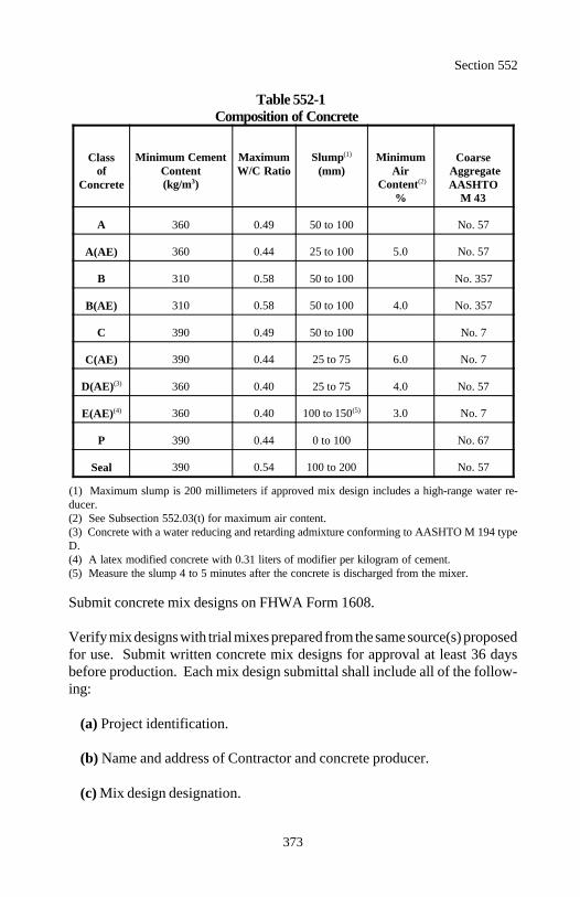
Section 552
373
Table 552-1Composition of Concrete
Class Coarse of Aggregate
Concrete AASHTO
Minimum Cement Maximum Slump MinimumContent W/C Ratio (mm) Air(kg/m ) Content3
(1)
(2)
% M 43
A 360 0.49 50 to 100 No. 57
A(AE) 360 0.44 25 to 100 5.0 No. 57
B 310 0.58 50 to 100 No. 357
B(AE) 310 0.58 50 to 100 4.0 No. 357
C 390 0.49 50 to 100 No. 7
C(AE) 390 0.44 25 to 75 6.0 No. 7
D(AE)(3) 360 0.40 25 to 75 4.0 No. 57
E(AE)(4) 360 0.40 100 to 150 3.0 No. 7(5)
P 390 0.44 0 to 100 No. 67
Seal 390 0.54 100 to 200 No. 57
(1) Maximum slump is 200 millimeters if approved mix design includes a high-range water re-ducer.(2) See Subsection 552.03(t) for maximum air content.(3) Concrete with a water reducing and retarding admixture conforming to AASHTO M 194 typeD.(4) A latex modified concrete with 0.31 liters of modifier per kilogram of cement.(5) Measure the slump 4 to 5 minutes after the concrete is discharged from the mixer.
Submit concrete mix designs on FHWA Form 1608.
Verify mix designs with trial mixes prepared from the same source(s) proposedfor use. Submit written concrete mix designs for approval at least 36 daysbefore production. Each mix design submittal shall include all of the follow-ing:
(a) Project identification.
(b) Name and address of Contractor and concrete producer.
(c) Mix design designation.
Section 552
374
(d) Class of concrete and intended use.
(e) Material proportions.
(f) Name and location of material sources for aggregate, cement, admixtures,and water.
(g) Type of cement and type of cement replacement if used. Fly ash, groundiron blast-furnace slag, or silica fume may partially replace cement as followsin any mix design except for prestressed concrete:
(1) Fly ash.
(1) Class F. Not more than 20 percent of the minimum mass of port-land cement in Table 552-1 may be replaced with class F fly ash at therate of 1.5 parts fly ash per 1 part cement.
(2) Class C. Not more than 25 percent of the minimum mass of port-land cement in Table 552-1 may be replaced with class C fly ash at therate of 1 part fly ash per 1 part cement.
(2) Ground iron blast-furnace slag. Not more than 50 percent of theminimum mass of portland cement in Table 552-1 may be replaced withground iron blast-furnace slag at the rate of 1 part slag per 1 part cement.
(3) Silica fume (microsilica). Not more than 10 percent of the minimummass of portland cement in Table 552-1 may be replaced with silica fumeat the rate of 1 part silica fume per 1 part cement.
The water/cement ratio for modified concrete is the ratio of the mass of waterto the combined masses of portland cement and cement substitute.
(h) Cement content in kilograms per cubic meter of concrete.
(i) The saturated surface dry batch mass of the coarse and fine aggregate inkilograms per cubic meter of concrete.
Section 552
375
(j) Water content (including free moisture in the aggregate plus water in thedrum, exclusive of absorbed moisture in the aggregate) in kilograms percubic meter of concrete.
(k) Target water/cement ratio.
(l) Dosage of admixtures. Entrained air may be obtained either by the use ofan air-entraining portland cement or by the use of an air entraining admix-ture. Do not use set accelerating admixtures with class P (prestressed) con-crete. Do not mix chemical admixtures from different manufacturers. Do notuse high range water reducers for bridge decks.
(m) Sieve analysis of fine and coarse aggregate.
(n) Absorption of fine and coarse aggregate.
(o) Bulk specific gravity (dry and saturated surface dry) of fine and coarseaggregate.
(p) Dry rodded unit mass of coarse aggregate in kilograms per cubic meter.
(q) Fineness modulus (FM) of fine aggregate.
(r) Material certifications for cement, admixtures, and aggregate.
(s) Target values for concrete slump with and without high-range waterreducers.
(t) Target values for concrete air content. Include the proposed range of aircontent for concrete to be incorporated into the work. Describe the methodsby which air content will be monitored and controlled. Provide acceptabledocumentation that the slump and compressive strength of the concrete arewithin specified limits throughout the full range of proposed air content. Inthe absence of such acceptable documentation, the maximum air content shallbe 10 percent.
(u) Concrete unit mass.
Section 552
376
(v) Compressive strengths of 7 and 28-day concrete. Pending 28-daystrength results, a mix design may be approved on the basis that the 7-daycompressive strength results equal or exceed 85 percent of the minimumstrength requirements when no accelerators or early strength cements areused.
(w) Material samples if requested.
Begin production only after the mix design is approved.
Furnish a new mix design for approval if there is a change in a source of mate-rial or when the fineness modulus of the fine aggregate changes by more than0.20.
552.04 Storage and Handling of Material. Store and handle all material ina manner that prevents segregation, contamination, or other harmful effects.Do not use cement and fly ash containing evidence of moisture contamination.Store and handle aggregate in a manner that ensures a uniform moisture contentat the time of batching.
552.05 Measuring Material. Batch the concrete according to the approvedmix design and the following tolerances:
Cement ±1 percentWater ±1 percentAggregate ±2 percentAdditive ±3 percent
A calibrated volumetric system may be used if the specified tolerances aremaintained.
552.06 Batching Plant, Mixers, and Agitators. Use a batching plant, mixer,and agitator conforming to AASHTO M 157. Continuous volumetric mixingequipment shall conform to AASHTO M 241.
552.07 Mixing. Mix the concrete in a central-mix plant or in truck mixers.Operate all equipment within manufacturer's recommended capacity. Produceconcrete of uniform consistency.
Section 552
377
(a) Central-mix plant. Dispense liquid admixtures through a controlledflowmeter. Use dispensers with sufficient capacity to measure, at one time,the full quantity of admixture required for each batch. If more than oneadmixture is used, dispense each with separate equipment.
Charge the coarse aggregate, one third of the water, and all air entraining ad-mixture into the mixer first, then add remainder of the material.
Mix for at least 50 seconds. Begin mixing time after all cement and aggre-gate are in the drum. Add the remaining water during the first quarter of themixing time. Add 4 seconds to the mixing time if timing starts the instant theskip reaches its maximum raised position. Transfer time in multiple-drummixers is included in mixing time. Mixing time ends when the dischargechute opens.
Remove the contents of an individual mixer before a succeeding batch ischarged into the drum.
(b) Truck mixer. Do not use mixers with any section of the blades worn 25millimeters or more below the original manufactured height. Do not usemixers and agitators with accumulated hard concrete or mortar in the mixingdrum.
Add admixtures to the mix water before or during mixing.
Charge the batch into the drum so a portion of the mixing water enters inadvance of the cement.
Mix each batch of concrete not less than 70 nor more than 100 revolutionsof the drum or blades at mixing speed. Begin the count of mixing revolutionsas soon as all material, including water, is in the mixer drum.
552.08 Delivery. Produce and deliver concrete to permit a continuous place-ment with no concrete achieving initial set before the remaining concrete beingplaced adjacent to it. Use methods of delivering, handling, and placing thatwill minimize rehandling of the concrete and prevent any damage to the struc-ture.
Do not place concrete that has developed an initial set. Never re-temper con-crete by adding water.
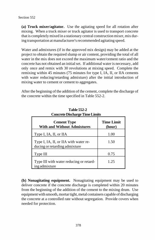
Section 552
378
(a) Truck mixer/agitator. Use the agitating speed for all rotation aftermixing. When a truck mixer or truck agitator is used to transport concretethat is completely mixed in a stationary central construction mixer, mix dur-ing transportation at manufacturer's recommended agitating speed.
Water and admixtures (if in the approved mix design) may be added at theproject to obtain the required slump or air content, providing the total of allwater in the mix does not exceed the maximum water/cement ratio and theconcrete has not obtained an initial set. If additional water is necessary, addonly once and remix with 30 revolutions at mixing speed. Complete theremixing within 45 minutes (75 minutes for type I, IA, II, or IIA cementswith water reducing/retarding admixture) after the initial introduction ofmixing water to cement or cement to aggregates.
After the beginning of the addition of the cement, complete the discharge ofthe concrete within the time specified in Table 552-2.
Table 552-2Concrete Discharge Time Limits
Cement Type Time LimitWith and Without Admixtures (hour)
Type I, IA, II, or IIA 1.00
Type I, IA, II, or IIA with water re- 1.50ducing or retarding admixture
Type III 0.75
Type III with water reducing or retard- 1.25ing admixture
(b) Nonagitating equipment. Nonagitating equipment may be used todeliver concrete if the concrete discharge is completed within 20 minutesfrom the beginning of the addition of the cement to the mixing drum. Useequipment with smooth, mortar tight, metal containers capable of dischargingthe concrete at a controlled rate without segregation. Provide covers whenneeded for protection.
Section 552
379
552.09 Quality Control of Mix. Submit and follow a quality control planaccording to Sections 153 and 154 as applicable and the following.
(a) Mixing. Designate a competent and experienced concrete technician tobe at the mixing plant in charge of the mixing operations and to be responsi-ble for the overall quality control including:
(1) The proper storage and handling of all components of the mix.
(2) The proper maintenance and cleanliness of plant, trucks, and otherequipment.
(3) The gradation testing of fine and coarse aggregates.
(4) The determination of the fineness modulus of fine aggregate.
(5) The measurement of moisture content of the aggregates and adjustingthe mix proportions as required before each day's production or moreoften if necessary to maintain the required water/cement ratio.
(6) The computation of the batch masses for each day's production and thechecking of the plant's calibration as necessary.
(7) The completion of batch tickets. Include the following information:
(a) Concrete supplier(b) Ticket serial number
(c) Date and truck number(d) Contractor(e) Structure or location of placement(f) Mix-design and concrete class(g) Component quantities and concrete total volume(h) Moisture corrections for aggregate moisture(i) Total water in mix at plant(j) Time of batching and time at which discharge must be completed(k) Maximum water that may be added to the mix at the project
Provide equipment necessary for the above tests and controls. Furnish copiesof work sheets for (3), (4), (5), and (6) as they are completed.
Section 552
380
(b) Delivery and sampling. Designate at least one competent and expe-rienced concrete technician to be at the project and be responsible for con-crete delivery, discharge operations, and sampling that include the following:
(1) The verification that adjustments to the mix before discharge complywith the specifications.
(2) The completion of the batch ticket, the recording of the apparent wa-ter/cement ratio, and the time discharge is completed. Furnish a copy ofeach batch ticket at the time of placement.
(3) The furnishing of all equipment and the performing of temperature,unit mass, air content, slump, and other tests to verify specificationcompliance before and during each placement operation.
Sample every batch after at least 0.2 cubic meters are discharged and be-fore placing any of the batch in the forms. When continuous mixing isused, sample approximately every 7.5 cubic meters. Test the air contentaccording to AASHTO T 152 or AASHTO T 196.
Test unit mass, slump, and temperature according to Subsection 552-.19.
If 3 successive samples are tested and compliance to the specifications isindicated, screening tests may be reduced to an approved frequency. Re-sume initial testing frequency if a test shows a failing temperature, aircontent, slump or when directed.
If there is no prior experience with the approved mix design or if specialhandling procedures, such as pumping, change of one or more of thecharacteristics between discharge of the load and placing in the forms,correlate the discharge tests with the placement tests to define thesechanges. Provide documentation. Repeat the correlations as often asnecessary or as directed.
(4) Take samples according to AASHTO T 141 from specified loads.Composite samples are not required. The point of sampling is from thedischarge stream at the point of placement. Provide cylinder molds.Make at least 4 compressive strength test cylinders, provide the appropri-ate initial curing, and carefully transport the cylinders to the project cur-ing facility. Two of the 4 cylinders will be used for 28-day compressivestrength tests. The remaining cylinders will be used for verification,
Section 552
381
projected strengths, or other purposes specified. Assist in the performingof other tests as requested.
552.10 Temperature and Weather Conditions. Maintain the temperatureof the concrete mixture just before placement between 10 and 30 C, exceptmaintain the concrete for bridge decks between 10 and 25 C.
(a) Cold weather. Cold weather is defined as any time during the concreteplacement or curing period the ambient temperature at the work site dropsbelow 2 C or the ambient temperature at the site drops below 10 Cfor a period of 12 hours or more.
When cold weather is reasonably expected or has occurred within 7 days ofanticipated concrete placement, submit a detailed plan for the producing,transporting, placing, protecting, curing, and temperature monitoring ofconcrete during cold weather. Include procedures for accommodating abruptchanges in weather conditions. Do not commence placement until plan isaccepted. Acceptance of a plan will take at least 1 day.
Have all material and equipment required for protection available at or nearthe project before commencing cold weather concreting.
Remove all snow, ice, and frost from the surfaces, including reinforcementand subgrade, against which the concrete is to be placed. The temperatureof any surface that will come into contact with fresh concrete shall be at least2 C and shall be maintained at a temperature of 2 C or above during theplacement of the concrete.
Place heaters and direct ducts so as not to cause concrete drying or fire haz-ards. Vent exhaust flue gases from combustion heating units to the outsideof any enclosures. Heat the concrete components in a manner that is notdetrimental to the mix. Do not heat cement or permit the cement to comeinto contact with aggregates that are hotter than 40 C. Concrete at the timeof placement shall be of uniform temperature and free of frost lumps. Do notheat aggregates with a direct flame or on sheet metal over fire. Do not heatfine aggregate by direct steam. The addition of salts to prevent freezing isnot permitted.
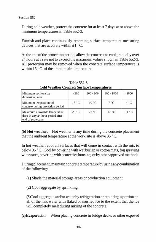
Section 552
382
During cold weather, protect the concrete for at least 7 days at or above theminimum temperatures in Table 552-3.
Furnish and place continuously recording surface temperature measuringdevices that are accurate within ±1 C.
At the end of the protection period, allow the concrete to cool gradually over24 hours at a rate not to exceed the maximum values shown in Table 552-3.All protection may be removed when the concrete surface temperature iswithin 15 C of the ambient air temperature.
Table 552-3Cold Weather Concrete Surface Temperatures
Minimum section size <300 300 - 900 900 - 1800 >1800dimension, mm
Minimum temperature of 13 C 10 C 7 C 4 Cconcrete during protection period
Maximum allowable temperature 28 C 22 C 17 C 11 Cdrop in any 24-hour period afterend of protection
(b) Hot weather. Hot weather is any time during the concrete placementthat the ambient temperature at the work site is above 35 C.
In hot weather, cool all surfaces that will come in contact with the mix tobelow 35 C. Cool by covering with wet burlap or cotton mats, fog sprayingwith water, covering with protective housing, or by other approved methods.
During placement, maintain concrete temperature by using any combinationof the following:
(1) Shade the material storage areas or production equipment.
(2) Cool aggregate by sprinkling.
(3) Cool aggregate and/or water by refrigeration or replacing a portion orall of the mix water with flaked or crushed ice to the extent that the icewill completely melt during mixing of the concrete.
(c) Evaporation. When placing concrete in bridge decks or other exposed
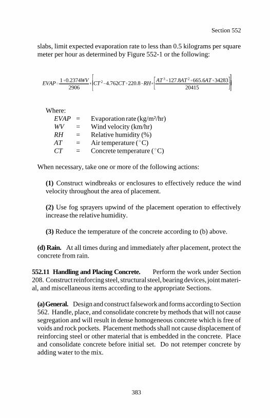
EVAP 1 0.2374WV2906
CT 2 4.762CT 220.8 RH AT 3 127.8AT 2 665.6AT 3428320415
Section 552
383
slabs, limit expected evaporation rate to less than 0.5 kilograms per squaremeter per hour as determined by Figure 552-1 or the following:
Where:EVAP = Evaporation rate (kg/m²/hr)WV = Wind velocity (km/hr)RH = Relative humidity (%)AT = Air temperature ( C)CT = Concrete temperature ( C)
When necessary, take one or more of the following actions:
(1) Construct windbreaks or enclosures to effectively reduce the windvelocity throughout the area of placement.
(2) Use fog sprayers upwind of the placement operation to effectivelyincrease the relative humidity.
(3) Reduce the temperature of the concrete according to (b) above.
(d) Rain. At all times during and immediately after placement, protect theconcrete from rain.
552.11 Handling and Placing Concrete. Perform the work under Section208. Construct reinforcing steel, structural steel, bearing devices, joint materi-al, and miscellaneous items according to the appropriate Sections.
(a) General. Design and construct falsework and forms according to Section562. Handle, place, and consolidate concrete by methods that will not causesegregation and will result in dense homogeneous concrete which is free ofvoids and rock pockets. Placement methods shall not cause displacement ofreinforcing steel or other material that is embedded in the concrete. Placeand consolidate concrete before initial set. Do not retemper concrete byadding water to the mix.
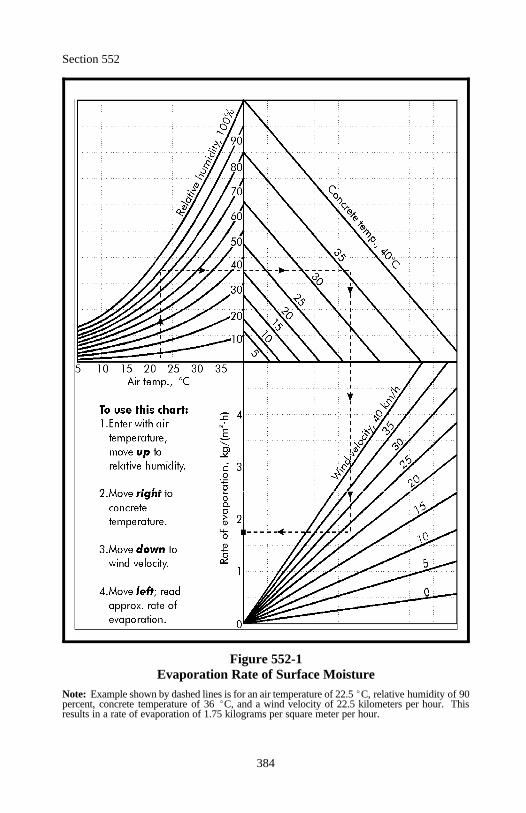
Section 552
384
Figure 552-1Evaporation Rate of Surface Moisture
Note: Example shown by dashed lines is for an air temperature of 22.5 C, relative humidity of 90percent, concrete temperature of 36 C, and a wind velocity of 22.5 kilometers per hour. Thisresults in a rate of evaporation of 1.75 kilograms per square meter per hour.
Section 552
385
Do not place concrete until the forms, all embedded material, and the ade-quacy of the foundation material have been inspected.
Remove all mortar, debris, and foreign material from the forms and rein-forcing steel before commencing placement. Thoroughly moisten the formsand subgrade immediately before concrete is placed against them. Tempo-rary form spreader devices may be left in place until concrete placementprecludes their need, after which they shall be removed.
Place concrete continuously without interruption between planned construc-tion or expansion joints. The delivery rate, placing sequence, and methodsshall be such that fresh concrete is always placed and consolidated againstpreviously placed concrete before initial set has occurred in the previouslyplaced concrete. Do not allow the time between the placement of successivebatches to exceed 30 minutes.
During and after placement of concrete, do not damage previously placedconcrete or break the bond between the concrete and reinforcing steel. Keepworkers off fresh concrete. Do not support platforms for workers and equip-ment directly on reinforcing steel. Once the concrete is set, do not disturbthe forms or reinforcing bars that project from the concrete until it is of suffi-cient strength to resist damage.
(b) Sequence of placement.
(1) Substructures. Do not place loads on finished bents, piers, or abut-ments until concrete cylinder tests from the same concrete cured under thesame conditions as the substructure element indicate that all concrete hasat least 80 percent of its required 28-day compressive strength.
(2) Vertical members. For vertical members over 5 meters in height,allow the concrete to set for at least 4 hours before placing concrete forintegral horizontal members. For vertical members less than 5 meters inheight, allow the concrete to set for at least 30 minutes. Do not applyloads from horizontal members until the vertical member has attained itsrequired strength.
Section 552
386
(3) Superstructures. Do not place concrete in the superstructure untilsubstructure forms have been stripped sufficiently to determine the ac-ceptability of the supporting substructure concrete. Do not place concretein the superstructure until the substructure has attained the requiredstrength.
Place concrete for T-beams in 2 separate operations. Wait at least 5 daysafter stem placement before placing the top deck slab concrete.
Concrete for box girders may be placed in 2 or 3 separate operationsconsisting of bottom slab, girder webs, and top slab or as shown on theplans. However, place the bottom slab first and do not place the top slabuntil the girder webs have been in place for at least 5 days.
(4) Arches. Place concrete in arch rings so the centering is loaded uni-formly and symmetrically.
(5) Box culverts. Place the base slab of box culverts and allow to set 24hours before the remainder of the culvert is constructed. For sidewallheights of 1.5 meters or less, the sidewalls and top slab may be placed inone continuous operation. For sidewalls greater than 1.5 meters but lessthan 5 meters in height, allow sidewall concrete to set at least 30 minutesbefore placing concrete in the top slab. For sidewalls 5 meters or higher,allow sidewall concrete to set at least 12 hours before placing concrete inthe top slab.
(6) Precast elements. Place and consolidate concrete so that shrinkagecracks are not produced in the member.
(c) Placing methods. Use equipment of sufficient capacity that is designedand operated to prevent mix segregation and mortar loss. Do not use equip-ment that causes vibrations that could damage the freshly placed concrete.Do not use equipment with aluminum parts that come in contact with theconcrete. Remove set or dried mortar from inside surfaces of placing equip-ment.
Place concrete as near as possible to its final position. Do not place concretein horizontal layers greater than 0.5 meter thick. Do not exceed the vibratorcapacity to consolidate and merge the new layer with the previous layer. Donot place concrete at a rate that, when corrected for temperature, exceeds thedesign loading of the forms.
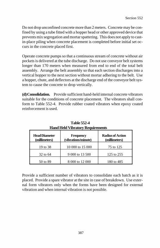
Section 552
387
Do not drop unconfined concrete more than 2 meters. Concrete may be con-fined by using a tube fitted with a hopper head or other approved device thatprevents mix segregation and mortar spattering. This does not apply to cast-in-place piling when concrete placement is completed before initial set oc-curs in the concrete placed first.
Operate concrete pumps so that a continuous stream of concrete without airpockets is delivered at the tube discharge. Do not use conveyor belt systemslonger than 170 meters when measured from end to end of the total beltassembly. Arrange the belt assembly so that each section discharges into avertical hopper to the next section without mortar adhering to the belt. Usea hopper, chute, and deflectors at the discharge end of the conveyor belt sys-tem to cause the concrete to drop vertically.
(d) Consolidation. Provide sufficient hand-held internal concrete vibratorssuitable for the conditions of concrete placement. The vibrators shall con-form to Table 552-4. Provide rubber coated vibrators when epoxy coatedreinforcement is used.
Table 552-4Hand Held Vibratory Requirements
Head Diameter Frequency Radius of Action(millimeters) (vibrations/minute) (millimeters)
19 to 38 10 000 to 15 000 75 to 125
32 to 64 9 000 to 13 500 125 to 255
50 to 89 8 000 to 12 000 180 to 485
Provide a sufficient number of vibrators to consolidate each batch as it isplaced. Provide a spare vibrator at the site in case of breakdown. Use exter-nal form vibrators only when the forms have been designed for externalvibration and when internal vibration is not possible.
Section 552
388
Consolidate all concrete by mechanical vibration immediately after place-ment. Manipulate vibrators to thoroughly work the concrete around rein-forcement, embedded fixtures, corners, and angles in the forms. Do notcause segregation. Do not consolidate concrete placed underwater. Sup-plement vibration with spading, as necessary, to ensure smooth surfaces anddense concrete along form surfaces, in corners, and at locations impossibleto reach with the vibrators.
Vibrate the concrete at the point of deposit and at uniformly spaced pointsnot farther apart than 1.5 times the radius over which the vibration is visiblyeffective. Insert vibrators so that the affected vibrated areas overlap. Do notuse vibrators to move concrete. Insert vibrators vertically and slowly with-draw from the concrete. The vibration shall be of sufficient duration andintensity to thoroughly consolidate the concrete, but not to cause segregation.Do not vibrate at any one point long enough to cause localized areas of groutto form. Do not vibrate reinforcement.
(e) Underwater placement. Underwater placement of concrete is permittedonly for seal concrete and drilled shafts. If other than seal concrete is used,increase the minimum cement content by 10 percent. Use tremies, concretepumps, or other approved methods for placement.
(1) Tremies. Use watertight tremies, with a diameter of 250 millimetersor more. Fit the top with a hopper. Use multiple tremies as required.Make tremies capable of being rapidly lowered to retard or stop the flowof concrete.
At the start of concrete placement, seal the discharge end and fill thetremie tube with concrete. Keep the tremie tube full of concrete to thebottom during placement. If water enters the tube, withdraw the tremieand reseal the discharge end. Maintain continuous concrete flow until theplacement is completed.
(2) Concrete pumps. Use pumps with a device at the end of the dis-charge tube to seal out water while the tube is first being filled with con-crete. When concrete flow is started, keep the end of the discharge tubefull of concrete and below the surface of the deposited concrete untilplacement has been completed.
Section 552
389
Place underwater concrete continuously from start to finish in a dense mass.Place each succeeding layer of concrete before the preceding layer has takeninitial set. Use more than one tremie or pump as necessary to ensure compli-ance with this requirement. Keep the concrete surface as horizontal as practi-cable. Do not disturb after placement. Maintain still water at the point ofdeposit.
Dewater after test specimens cured under similar conditions indicate that theconcrete has sufficient strength to resist the expected loads. Remove alllaitance or other unsatisfactory material from the exposed concrete.
(f) Concrete railings and parapets. Use smooth, tight fitting, rigid forms.Neatly miter corners. Place concrete railings and parapets after the centeringor falsework for the supporting span is released. Remove forms withoutdamaging the concrete. Finish all corners to be true, clean-cut, and free fromcracks, spalls, or other defects.
Cast precast railing members in mortar-tight forms. Remove precast mem-bers from molds as soon as the concrete has sufficient strength to be self-supporting. Protect edges and corners from chipping, cracking, and otherdamage. Cure in accordance with Subsection 552.15(b). The curing periodmay be shortened, as approved, by using moist heat and/or type III cementor water reducing agents.
552.12 Construction Joints. Provide construction joints at locations shownon the plans. Written approval is required for any additional constructionjoints.
At horizontal construction joints, place gauge strips inside the forms along allexposed faces to produce straight joint lines. Clean and saturate constructionjoints before placing fresh concrete. Keep joints saturated until adjacent freshconcrete is placed. Immediately before placing new concrete, draw formstightly against previously placed concrete. Where accessible, thoroughly coatthe existing surface with a very thin coating of cement mortar. Extend reinforc-ing bars across construction joints.
Section 552
390
552.13 Expansion and Contraction Joints.
(a) Open joints. Form open joints with a wooden strip, metal plate, or otherapproved material. Remove the joint forming material without chipping orbreaking the corners of the concrete. Do not extend reinforcement across anopen joint.
(b) Filled joints. Cut premolded expansion joint filler to the shape and sizeof the surface being jointed. Secure the joint filler on one surface of the jointusing galvanized nails or other acceptable means. Splice according to themanufacturer's recommendations. After form removal, remove and neatly cutall concrete or mortar that has sealed across the joint. Fill all joint gaps 3millimeters or wider with hot asphalt or other approved filler. Place allnecessary dowels, load transfer devices, and other devices as shown on theplans or as directed.
(c) Steel joints. Fabricate plates, angles, or other structural shapes accu-rately to conform to the concrete surface. Set joint opening to conform to theambient temperature at the time of concrete placement. Securely fasten thejoints to keep them in correct position. Maintain an unobstructed joint open-ing during concrete placement.
(d) Water stops. Construct water stops according to Section 560.
(e) Compression joint seals. Use one-piece compression joint seals fortransverse joints and the longest practicable length for longitudinal joints.Clean and dry joints and remove spalls and irregularities. Apply a lubri-cant-adhesive as a covering film to both sides of the seal immediately beforeinstallation. Compress the seal and place it in the joint as recommended bythe manufacturer. Make sure the seal is in full contact with the joint wallsthroughout its length.
Remove and discard all seals that are twisted, curled, nicked or improperlyformed. Remove and reinstall joint seals that elongate more than 5 percentof their original length when compressed. Remove all excess lubricant-adhesive before it dries.
(f) Elastomeric expansion joint seal. Install the joint according to themanufacturer's recommendations and in conformance with the plans.
Section 552
391
552.14 Finishing Plastic Concrete. Strike off concrete surfaces which arenot placed against forms. Float finish the concrete surface. Remove any lai-tance or thin grout. Carefully tool all nonchamfered edges with an edger.Leave edges of joint filler exposed.
Protect the surface from rain damage.
Finish all concrete surfaces used by traffic to a skid-resistant surface. Provideat least 2 suitable and adequate work bridges.
(a) Striking off and floating. For bridge decks or top slabs of structuresserving as finished pavements, use an approved power driven finishing ma-chine equipped with oscillating screed. If approved, use hand-finishingmethods for irregular areas where the use of a machine is impractical.
Strike off all surfaces using equipment supported by and traveling on screedrails or headers. Do not support rails within the limits of the concrete place-ment without approval.
Set rails or headers on nonyielding supports so the finishing equipment oper-ates without interruption over entire surface being finished. Extend railsbeyond both ends of the scheduled concrete placement a sufficient distanceto enable finishing machine to finish the concrete being placed.
Set rails the entire length of steel girder superstructures.
Adjust rails, headers, and strike-off equipment to the required profile andcross-section allowing for anticipated settlement, camber, and deflection offalsework.
Before beginning delivery and placement of concrete, operate the finishingmachine over the entire area to be finished to check for excessive rail deflec-tions, deck thickness, reinforcing steel cover, and to verify proper operationof equipment. Make necessary corrections before concrete placement begins.
Section 552
392
After placing the concrete, operate finishing machine over the concrete asneeded to obtain the required profile and cross-section. Keep a slight roll ofexcess concrete in front of the cutting edge of the screed at all times. Main-tain this excess of concrete to the end of the pour or form and then removeand waste it. Adjust rails or headers as necessary to correct for unanticipatedsettlement or deflection.
Remove rail supports embedded in the concrete to at least 50 millimetersbelow the finished surface and fill and finish any voids with fresh concrete.Finish the surface with a float, roller or other approved device as necessaryto remove all local irregularities.
Remove all excess water, laitance, or foreign material brought to the surfaceusing a squeegee or straightedge drawn from the center of the slab towardseither edge. Do not apply water to the surface of the concrete during finish-ing operations.
(b) Straightedging. Check all slab and sidewalk surfaces. Check the entiresurface parallel to the centerline of the bridge with a 3-meter metal straight-edge. Overlap the straightedge at least half the length of the previousstraightedge placement.
Correct deviations in excess of 3 millimeters from the testing edge of thestraightedge. For deck surfaces that are to receive an overlay, correct devia-tions in excess of 6 millimeters.
(c) Texturing. Produce a skid-resistant surface texture on all driving sur-faces by grooving. Use one of the following finishes or a combination there-of for other surfaces as required.
(1) Grooved finish. Use a float having a single row of fins or an ap-proved machine designed specifically for sawing grooves in concretepavements. Space fins 10 to 20 millimeters on centers. Make the grooves2 to 5 millimeters wide and 3 to 5 millimeters deep. Groove perpendicu-lar to the centerline without tearing the concrete surface or looseningsurface aggregate.
If grooves are sawn, cut the grooves approximately 5 millimeters wide ata spacing of 15 to 25 millimeters.
Section 552
393
On bridge decks, discontinue grooving 300 millimeters from curb faceand provide a longitudinal troweled finish on the surface of gutters.
(2) Sidewalk finish. Strike off the surface using a strike board and thenfloat the surface. Use an edging tool on edges and expansion joints.Broom the surface using a broom with stiff bristles, broom perpendicularto the centerline from edge to edge with adjacent strokes slightly over-lapped. Produce regular corrugations not over 3 millimeters in depthwithout tearing the concrete. While the concrete is plastic, correct porousspots, irregularities, depressions, small pockets, and rough spots. Groovecontraction joints at the required interval using an approved groovingtool.
(3) Troweled and brushed finish. Use a steel trowel to produce a slick,smooth surface free of bleed water. Brush the surface with a fine brushusing parallel strokes.
(4) Exposed aggregate finish. Strike off the surface using a strike boardand then float the surface. Use an edging tool on all transverse and longi-tudinal joints that are against forms or existing pavement. Do not edgetransverse joints in a continuous lane pour or longitudinal joints in acontinuous dual lane pour.
As soon as the concrete hardens sufficiently to prevent particles of gravelfrom being dislodged, broom the surface. Use stiff brushes approved bythe CO. Exercise care to prevent marring of the surface and cracking orchipping of slab edges or joints. If approved by the CO, apply a lightspray of retardant to the unfinished surface to facilitate this work.
First, broom transversely across the pavement. Pull the loosened semi-stiff mortar entirely off the pavement. Remove the mortar from all adja-cent pavements. Then broom parallel to the pavement centerline. Contin-ue this operation until a sufficient amount of coarse aggregate is exposed.Other methods of aggregate exposure, such as using a water spray attach-ment on a special exposed aggregate broom, will be permitted if satisfac-tory results are demonstrated.
Section 552
394
After curing according to Subsection 501.10, wash the surface with brushand water to remove all laitance and cement from the exposed coarseaggregate.
(d) Surface underneath bearings. Finish all bearing surfaces to within 5millimeters of plan elevation. When a masonry plate is to be placed directlyon the concrete or on filler material less than 5 millimeters thick, finish thesurface with a float to an elevation slightly above plan elevation. After theconcrete is set, grind the surface as necessary to provide a full and evenbearing.
When a masonry plate is to be set on filler material between 5 and 15 milli-meters thick, finish the surface with a steel trowel. Finish or grind the sur-face so that it does not vary from a straightedge in any direction by more than2 millimeters.
When a masonry plate is to be set on filler material greater than 15 milli-meters thick or when an elastomeric bearing pad is to be used, finish the sur-face to a plane surface free of ridges.
When required under a masonry plate or elastomeric bearing pad, use mortarin the proportions of 1 part portland cement and 1.5 parts clean sand. Thor-oughly mix sand and cement before adding water. Mix only enough mortarfor immediate use. Discard mortar that is more than 45 minutes old. Do notre-temper mortar. Cure mortar at least 3 days and do not apply loads tomortar for at least 48 hours. Do not mix and use mortar during freezingconditions. Mortar sand shall conform to AASHTO M 45. Proprietaryproducts may be used with approval.
(e) Surface underneath waterproofing membrane deck seal. Surfacesthat are to be covered with a waterproofing membrane deck seal shall not becoarse textured, but shall be finished to a smooth surface and free of ridgesand other projections.
552.15 Curing Concrete. Begin curing immediately after the free surfacewater has evaporated and the finishing is complete. If the surface of the con-crete begins to dry before the selected cure method can be implemented, keepconcrete surface moist using a fog spray without damaging the surface.
Section 552
395
Keep surfaces to be rubbed moist after forms are removed. Cure immediatelyfollowing the first rub.
Cure the top surfaces of bridge decks using the liquid membrane curing com-pound method combined with the water method. Apply liquid membranecuring compound immediately after finishing. Apply the water cure within 4hours after finishing.
Cure all concrete uninterrupted for at least 7 days. If pozzolans in excess of 10percent by mass of the portland cement is used in the mix, cure uninterruptedfor at least 10 days.
(a) Forms inplace method. For formed surfaces, leave the forms inplacewithout loosening. If forms are removed during the curing period to facili-tate rubbing, only strip forms from those areas able to be rubbed during thesame shift. During rubbing, keep the surface of the exposed concrete moist.After the rubbing is complete, continue curing process using the watermethod or by applying a clear curing compound (type 1 or type 1-D) for theremainder of the curing period.
(b) Water method. Keep the concrete surface continuously wet by ponding,spraying, or covering with material that is kept continuously and thoroughlywet. Covering material may consist of cotton mats, multiple layers of burlap,or other approved material that does not discolor or otherwise damage theconcrete.
Cover the covering material with a waterproof sheet material that preventsmoisture loss from the concrete. Use the widest sheets practical. Lap adja-cent sheets at least 150 millimeters and tightly seal all seams with pressuresensitive tape, mastic, glue, or other approved methods. Secure all materialso that wind will not displace it. Immediately repair sheets that are brokenor damaged.
(c) Liquid membrane curing compound method. Do not use the liquidmembrane method on surfaces to receive a rubbed finish. Use on construc-tion joint surfaces is permitted only if the compound is removed by sand-blasting before placement of concrete against the joint.
Use type 2, white pigmented, liquid membrane only on the top surfaces ofbridge decks or on surfaces not exposed to view in the completed work. Usetype 1 or 1-D clear curing compounds on other surfaces.
Section 552
396
Mix membrane curing solutions containing pigments before use. Continueto agitate during application. Use equipment capable of producing a finespray. Apply the curing compound at a minimum rate of 0.25 liter per squaremeter in one or two uniform applications. If the solution is applied in 2applications, follow the first application with the second application within30 minutes and apply at right angles to the first application.
If the membrane is damaged by rain or other means during the curing period,immediately apply a new coat over the damaged areas.
552.16 Finishing Formed Concrete Surfaces. Remove and replace or repair,as approved, all rock pockets or honeycombed concrete. Finish sound, formedconcrete surfaces as follows.
(a) Class 1 - ordinary surface finish. Finish the following surfaces with aclass 1, ordinary surface finish.
(1) Under surfaces of slab spans, box girders, filled spandrel arch spans,and the roadway deck slab between superstructure girders.
(2) Inside vertical surface or T-girders of superstructures.
(3) Surfaces to be buried and culvert surfaces above finished ground thatare not visible from the traveled way or a walkway.
Begin finishing as soon as the forms are removed. Remove fins and irregularprojections from all surfaces which are exposed or will be waterproofed.Remove bulges and offsets with carborundum stones or discs. Remove local-ized, poorly bonded rock pockets or honeycombed concrete and replace withsound concrete or packed mortar in an approved manner. Clean and point all form tie cavities, holes, broken corners and edges, andother defects. Saturate the area with water. Finish the area with mortar thatis less than 1 hour old. After the mortar is set, rub it (if required) and con-tinue curing. Match exposed surfaces to surrounding concrete.
Carefully tool and remove free mortar and concrete from construction andexpansion joints. Leave joint filler exposed for its full length with clean, trueedges.
Section 552
397
Rub or grind bearing surfaces on piers and abutments to the specified eleva-tion and slope.
If the final finished surface is not true and uniform, rub it according to (b)below.
(b) Class 2 - rubbed finish. Finish the following surfaces with a class 2,rubbed finish.
(1) All surfaces of bridge superstructures, except those surfaces designat-ed to receive a class 1 or other finish.
(2) All surfaces of bridge piers, piles, columns and abutments, and retain-ing walls above finished ground and to at least 300 millimeters belowfinished ground.
(3) All surfaces of open spandrel arch rings, spandrel columns and abut-ment towers.
(4) All surfaces of pedestrian undercrossings, except floors and surfacesto be covered with earth.
(5) Surfaces above finished ground of culvert headwalls and endwallswhen visible from the traveled way or walkway.
(6) Inside surfaces of culvert barrels higher than 1 meter that are visiblefrom the traveled way. Finish for a distance inside the barrel at leastequal to the height of the culvert.
(7) All surfaces of railings.
Complete a class 1 finish according to (a) above. Saturate the concrete sur-face with water. Rub the surface with a medium coarse carborundum stoneusing a small amount of mortar on its face. Use mortar composed of cementand fine sand mixed in the same proportions as the concrete being finished.Continue rubbing until form marks, projections, and irregularities are re-moved and a uniform surface is obtained. Leave the paste produced by thisrubbing in place.
Section 552
398
After other work which could affect the surface is complete, rub with a finecarborundum stone and water until the entire surface has a smooth textureand uniform color. After the surface has dried, rub it with burlap to removeloose powder. Leave it free from all unsound patches, paste, powder, andobjectionable marks.
(c) Class 3 - tooled finish. Let the concrete set for at least 14 days or longerif necessary to prevent the aggregate particles from being "picked" out of thesurface. Use air tools such as a bush hammer, pick, or crandall. Chip awaythe surface mortar and break the aggregate particles to expose a grouping ofbroken aggregate particles in a matrix of mortar.
(d) Class 4 - sandblasted finish. Let the concrete set for at least 14 days.Protect adjacent surfaces that are not to be sandblasted. Sandblast the sur-face with hard, sharp sand to produce an even fine-grained surface in whichthe mortar is cut away leaving the aggregate exposed.
(e) Class 5 - wire brushed or scrubbed finish. Begin as soon as the formsare removed. Scrub the surface with stiff wire or fiber brushes using a solu-tion of muriatic acid. Mix the solution in the proportion of 1 part acid to 4parts water. Scrub until the cement film or surface is completely removedand the aggregate particles are exposed. Leave an evenly pebbled texturehaving the appearance of fine granite to coarse conglomerate depending uponthe size and grading of aggregate. Wash the entire surface with water con-taining a small amount of ammonia.
(f) Class 6 - color finish. Build a sufficient number of 0.5 by 1 meter con-crete color sample panels to obtain a color acceptable to the CO. Protect theapproved color sample panel at all times during the work. Color all desig-nated surfaces to match the color of the approved sample.
Complete a class 1 finish according to (a) above. Do not apply the colorfinish until all concrete placement for the structure is complete. Remove alldust, foreign matter, form oil, grease, and curing compound with a 5 percentsolution of trisodium phosphate and then rinse the concrete surface withclean water.
Section 552
399
Use paper, cloth, or other means to protect surfaces not to be color finished.Apply the finish to a dry concrete surface when the surface temperature is 4
C or higher and the air temperature in the shade is anticipated to be 4 C orhigher during the 24 hours following application.
Apply the color finish according to the manufacturer's recommendations.Spray, brush, or roll on the first coat of penetrating sealer and color base.Spray, brush, or roll on the finish coat after the first coat has thoroughlydried. Apply finish to provide a uniform, permanent color, free from runsand sags to the surfaces.
Clean concrete areas not intended to be covered by the finish using an ap-proved method.
552.17 Concrete Anchorage Devices. Use chemical, grouted, or cast-in-place concrete anchorage devices for attaching equipment or fixtures to con-crete.
Furnish the following for approval:
(a) Concrete anchorage device sample(b) Manufacturer's installation instructions(c) Material data and certifications
Fabricate all metal parts of the anchorage devices from stainless steel or fromsteel protected with a corrosion resistant metallic coating that does not reactchemically with concrete. Supply anchorage devices complete with all hard-ware.
For chemical or grouted anchors, conduct a system approval test on one anchoron the project, not to be incorporated in the work. Conduct a static load testaccording to ASTM E 488. Demonstrate that the anchorage device will with-stand a sustained direct tension test load not less than the values shown inTable 552-5 for a period of at least 48 hours with movement not to exceed 1millimeter. Also demonstrate that when loaded to failure, the anchor devicedemonstrates a ductile failure of the anchor steel, not a failure of the chemical,grout, or concrete.
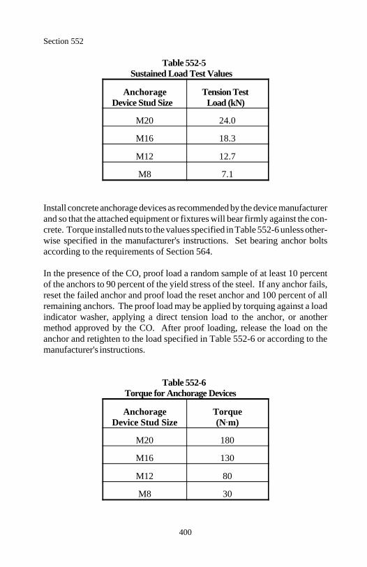
Section 552
400
Table 552-5Sustained Load Test Values
Anchorage Tension TestDevice Stud Size Load (kN)
M20 24.0
M16 18.3
M12 12.7
M8 7.1
Install concrete anchorage devices as recommended by the device manufacturerand so that the attached equipment or fixtures will bear firmly against the con-crete. Torque installed nuts to the values specified in Table 552-6 unless other-wise specified in the manufacturer's instructions. Set bearing anchor boltsaccording to the requirements of Section 564.
In the presence of the CO, proof load a random sample of at least 10 percentof the anchors to 90 percent of the yield stress of the steel. If any anchor fails,reset the failed anchor and proof load the reset anchor and 100 percent of allremaining anchors. The proof load may be applied by torquing against a loadindicator washer, applying a direct tension load to the anchor, or anothermethod approved by the CO. After proof loading, release the load on theanchor and retighten to the load specified in Table 552-6 or according to themanufacturer's instructions.
Table 552-6Torque for Anchorage Devices
Anchorage TorqueDevice Stud Size (N m)
M20 180
M16 130
M12 80
M8 30
Section 552
401
552.18 Loads on New Concrete Structures. Do not place any loads onfinished bents piers, or abutments until tests on concrete cylinders cast from thesame concrete and cured under the same conditions as the substructure elementindicate that the concrete has attained at least 80 percent of the specified mini-mum 28-day compressive strength. This restriction does not apply to place-ment of upper lifts for substructure elements cast in stages.
Do not allow vehicles or construction equipment on any span until concrete inthe entire superstructure has attained its design compressive strength and hasbeen in place 21 days.
For post-tensioned concrete structures, do not allow vehicles over 2000 kilo-grams on any span until the prestressing steel for that span is tensioned, grout-ed, and cured, the grout has obtained a strength of 21 megapascals, and the tierods are tightened. Vehicles weighing less than 2000 kilograms may be permit-ted on a span provided the mass of the vehicle was included in the falseworkdesign.
552.19 Acceptance. Material for concrete will be evaluated under Subsec-tions 106.02 and 106.03. Furnish a production certification for the portlandcement.
The concrete mixture's slump, air content, unit mass, and temperature will beevaluated under Subsections 106.02 and 106.04. See Table 552-1 for specifi-cation limits. See Table 552-7 for minimum sampling and testing.
Concrete compressive strength will be evaluated under Subsection 106.05. SeeTable 552-7 for minimum sampling and testing. The lower specification limitis the minimum required compressive strength at 28 days (f ) specified in thec
contract. A single compressive strength test result is the average result from2 cylinders cast from the same load and tested at 28 days. See Table 552-7 forthe acceptance quality characteristic category.
Remove and replace concrete represented by cylinders having a compressivestrength of less than 90 percent of the minimum 28-day compressive strength(f ) and so located as to cause an intolerably detrimental effect on the struc-c
ture.
Section 552
402
Construction (including batching, placing, finishing, and curing concrete) ofconcrete structures will be evaluated under Subsections 106.02 and106.04.
Falsework and forms will be evaluated under Section 562.
Measurement
552.20 Measure structural concrete and seal concrete by the cubic meter in thestructure.
Payment
552.21 The accepted quantities, measured as provided above, will be paid atthe contract price per unit of measurement for the pay items listed below thatare shown in the bid schedule except the structural concrete contract unit bidprice will be adjusted according to Subsection 106.05. Payment will be fullcompensation for the work prescribed in this Section. See Subsection 109.05.
Payment for a structural concrete will be made at a price determined by multi-plying the contract unit bid price by the compressive strength pay factor.
Payment will be made under:
Pay Item Pay Unit
55201 Structural concrete class ___ Cubic meter55202 Structural concrete class ___ for (description) Cubic meter55203 Structural concrete for (description) Cubic meter55204 Seal concrete for (description) Cubic meter
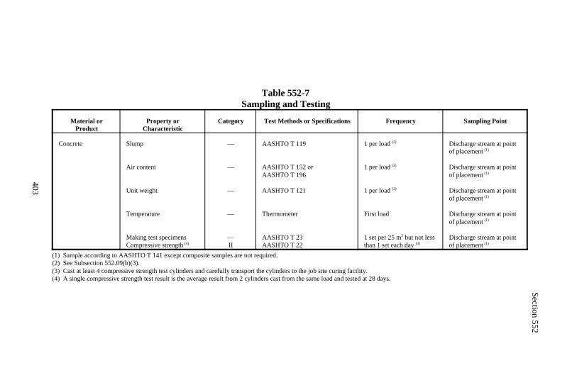
Section 552
403
Table 552-7Sampling and Testing
Material orProduct
Property orCharacteristic
Category Test Methods or Specifications Frequency Sampling Point
Concrete Slump
Air content
Unit weight
Temperature
Making test specimensCompressive strength (4)
—
—
—
—
—II
AASHTO T 119
AASHTO T 152 orAASHTO T 196
AASHTO T 121
Thermometer
AASHTO T 23AASHTO T 22
1 per load (2)
1 per load (2)
1 per load (2)
First load
1 set per 25 m but not less3
than 1 set each day (3)
Discharge stream at pointof placement (1)
Discharge stream at pointof placement (1)
Discharge stream at pointof placement (1)
Discharge stream at pointof placement (1)
Discharge stream at pointof placement (1)
(1) Sample according to AASHTO T 141 except composite samples are not required.(2) See Subsection 552.09(b)(3).(3) Cast at least 4 compressive strength test cylinders and carefully transport the cylinders to the job site curing facility.(4) A single compressive strength test result is the average result from 2 cylinders cast from the same load and tested at 28 days.
404
Section 553.) PRESTRESSED CONCRETE
Description
553.01 This work consists of prestressing precast or cast-in-place concrete byfurnishing, placing, and tensioning prestressing steel. It also includes installingall precast, prestressed members, except piling.
Material
553.02 Conform to the following Section and Subsections:
Anchorage devices 722.01Concrete 552Elastomeric bearing pads 717.10Grout 725.22Prestressing steel 709.03Reinforcing steel 709.01
Construction Requirements
553.03 Method Approval. Perform prestressing by either pretensioning orpost-tensioning methods. If a method is proposed that is not in the contract,submit detailed drawings of the method, material, and equipment proposed forapproval at least 30 days before starting prestressing. Show the following:
(a) Method and sequence of stressing(b) Complete specifications, details, and test results for the prestressing steeland anchoring devices(c) Anchoring stresses(d) Arrangement of the prestressing steel in the members(e) Tendon elongation calculations for jacking procedures to be used(f) Number, spacing, and method of draping pretensioned strands(g) Other substantiating calculations for the prestressing method(h) Type of tendon ducts for post-tensioning(i) Pressure grouting material and equipment for post-tensioning(j) Samples of wire or strand taken according to Subsection 709.03
Section 553
405
For on-site casting, submit drawings showing anticipated leveling or alterationsto the site. After completion of casting, clear the site of equipment and rubbishand restore it to an acceptable condition.
553.04 Prestressing Steel. Use prestressing steel that is bright and free ofcorrosion, dirt, grease, wax, scale, rust, oil, or other foreign material that mayprevent bond between the steel and the concrete. Do not use prestressing steelthat has sustained physical damage or is pitted.
One approved splice per pretensioning strand is permitted if the splice is be-tween members in the casting bed. Splice so the strands have the same "twist"or "lay."
Do not weld or ground welding equipment on forms or other steel in the mem-ber after the prestressing steel is installed.
Failure of one wire in a 7-wire prestressing strand is acceptable if 85 percentof the required tension load is attained before failure and if the failed stranddoes not constitute more than 2 percent of the total area of strands in anindividual beam or girder.
Extend bars using couplers which when assembled have a tensile strength notless than the tensile strength of the bars.
553.05 Concrete. Construct prestressed concrete according to Section 552.Construct reinforcing steel according to Section 554.
Do not place concrete in the forms until the placement of reinforcing steel,prestressing steel, ducts, bearing plates, and other embedded material is ap-proved. Place and vibrate concrete with care to avoid displacing the embeddedmaterial.
Make at least 2 release strength test cylinders according to AASHTO T 23 inaddition to those required to determine the 28-day compressive strength. Curethe release strength test cylinders with the concrete member they represent.
Rough cast the top surface of members against which concrete will be cast.
Section 553
406
Cure the girder in a saturated atmosphere of at least 90 percent relative humid-ity. Cure time may be shortened by heating the outside of impervious formswith radiant heat, convection heat, conducted steam, or hot air.
Apply radiant heat by means of pipes circulating steam, hot oil, hot water, orelectric heating elements. Inspect casting beds to ensure uniform heat applica-tion. Use a suitable enclosure to contain the heat. Minimize moisture loss bycovering all exposed concrete surfaces with plastic sheeting or liquid mem-brane curing compound according to Subsection 552.15. Sandblast curingcompound from all surfaces to which concrete will be bonded.
Envelop the entire surface with saturated steam. Completely enclose the cast-ing bed with a suitable type of housing, tightly constructed to prevent the es-cape of steam and exclude outside air. Use steam at 100 percent relative hu-midity. Do not apply the steam directly to the concrete.
With hot air, the CO will approve the method to envelop and maintain thegirder in a saturated atmosphere. Never allow dry heat to touch the girder sur-face.
With all heat curing methods:
(a) Keep all unformed girder surfaces in a saturated atmosphere throughoutthe curing time.(b) Embed a thermocouple (linked with a thermometer accurate to ±3C) 150 to 200 millimeters from the top or bottom of the girder on its center-
line and near its midpoint.(c) Monitor with a recording sensor (accurate to ±3 C) arranged and cali-brated to continuously record, date, and identify concrete temperaturethroughout the heating cycle.(d) Make the temperature record available to the CO.(e) Heat concrete to no more than 38 C during the first 2 hours after placingconcrete and increase the temperature no more than 14 C per hour to amaximum of 80 C.(f) Cool concrete, after curing is complete, no more than 14 C per hour, to38 C.(g) Keep the temperature of the concrete above 15 C until the girder reachesrelease strength.
Section 553
407
Cure precast, prestressed members until the concrete has attained the releasecompressive strength, required by the contract. The average strength of 2 testcylinders shall be greater than the minimum required strength. The individualstrength of any one cylinder shall not be more than 5 percent below the re-quired strength.
553.06 Tensioning. Use hydraulic jacks to tension prestressing steel. Use apressure gauge or load cell for measuring jacking force.
Calibrate measuring devices at least once every 6 months or if they appear tobe giving erratic results. Calibrate the jack and gauge as a unit with the cylin-der extension in the approximate position that it will be at final jacking force.Keep a certified calibration chart with each gauge.
If a pressure gauge is used, do not gauge loads less than 1/4 nor more than 3/4of the total graduated capacity of the gauge, unless calibration data clearlyestablishes consistent accuracy over a wider range. Use a pressure gauge withan accurate reading dial at least 150 millimeters in diameter.
Measure the force induced in the prestressing steel using jacking gauges andtake elongation measurements of the prestressing steel. If there is a discrep-ancy of more than 7 percent between the measured elongation and that ex-pected for the jacking force, check the entire operation, determine the reasonsfor the discrepancy, and correct before proceeding. Recalibrate jacking gaugesif their readings do not agree within 5 percent of each other. If the jackingsystem is equipped with an automatic release valve that closes when the re-quired prestressing force is reached, strand elongation measurements are onlyrequired for the first and last tendon tensioned and for at least 10 percent of theremaining tendons.
If a load cell is used, do not use the lower 10 percent of the manufacturer'srated capacity of the load cell to determine the jacking force.
Do not exceed a temporary tensile stress in prestressing steel of 80 percent ofthe specified minimum ultimate tensile strength of the prestressing steel. An-chor prestressing steel at an initial stress that will result in the retention of aworking stress after all losses of not less than those required.
Section 553
408
For pretensioned members, do not allow the initial release stress after seatingand before other losses to exceed 70 percent of the specified minimum ultimatetensile strength of the prestressing steel for stress relieved strands and 75 per-cent for low relaxation strands. For post-tensioned members, do not allow theinitial release stress after seating to exceed 70 percent of the specified mini-mum ultimate tensile strength of the prestressing steel.
553.07 Pretensioned Members. Cast pretensioned members to the tolerancesshown in Table 553-1.
(a) Prestressing steel. Protect prestressing steel placed in the stressing bedfrom contamination and corrosion if the stressing bed will be exposed toweather for more than 36 hours before encasement in concrete.
Free all strands of kinks or twists. Accurately hold prestressing steel inposition and tension according to Subsection 553.06. Do not allow strandsto unwind more than one turn. Keep a record of the jacking force and elon-gation measurements after the strands are tensioned to 20 percent of finaljacking force.
Tension prestressing steel to the required stress. Include in elongation com-putations strand anchorage slippage, splice slippage, horizontal movementof abutments, and prestressing steel temperature changes between the timeof tensioning and the time when the concrete takes its initial set. Maintain the prestress bed forms, strands, and reinforcement bar temperaturewithin 14 C of the temperature of the concrete to be placed in the forms.Support strands with rollers at points of direction change when strands aretensioned in a draped position. Use free running rollers with minimal fric-tion. Initially, when strands are tensioned and then pulled into the drapedposition, tension to no more than the required tension minus the increasedtension due to forcing the strand to a draped profile. If the load in a drapedstrand at the dead end, as determined by elongation measurements, is lessthan 95 percent of the jack load, tension the strand from both ends of the bed.Make the load, as computed from the sum of elongations produced by jack-ing at both ends, agree within 5 percent of the jack load.
Section 553
409
Within 3 hours before placing concrete, check the tension on the prestressingstrands. The method and equipment for checking the loss of prestress shallbe subject to approval by the CO. If strands are tensioned individually,check each strand for loss of prestress. Retension to the original computedjacking stress all strands that show a loss of prestress in excess of 3 percent.If strands are tensioned in a group, check the entire group for total loss ofprestress. Release and retension the entire group if the total prestress showsa loss in excess of 3 percent or if any individual strand appears significantlydifferent from the rest of the strands in the group.
(b) Releasing steel. Release the prestress load to the concrete after theconcrete has attained its required release compressive strength. Do not ex-pose the concrete to temperatures below freezing for at least 7 days aftercasting. Cut or release strands such that lateral eccentricity of the prestressforce will be minimized. Cut prestressing steel off flush with the end of themember.
553.08 Storing, Transporting, and Erecting. Do not ship prestressed con-crete members until concrete cylinder tests manufactured of the same concreteand cured under the same conditions as the members indicate that the concretein each member has attained the minimum required design strength and is atleast 14 days old.
Store, transport, and erect precast, prestressed girders, slab units, and box unitsin the upright position with the points of support and directions of the reac-tions, with respect to the member, approximately the same as when the memberis in its final position. Prevent cracking or damage during storage, hoisting,and handling of the precast units. Replace units damaged by improper storageor handling.
553.09 Post-Tensioned Members. Construct post-tensioned members to thetolerances shown in Table 553-1. Construct supporting falsework so that thesuperstructure is free to lift off the falsework and shorten during post-ten-sioning. Detail formwork left inside box girders to support the roadway slabto offer minimum resistance to girder shortening due to shrinkage and post-tensioning.
Section 553
410
(a) Ducts. Use rigid, mortar tight, galvanized ferrous metal ducts fabricatedwith either welded or interlocked seams with sufficient strength to maintaincorrect alignment during concrete placement and with minimum wall thick-ness as follows:
(1) 0.55 millimeter for ducts 65 millimeter diameter(2) 0.70 millimeter for ducts > 65 millimeter diameter(3) 0.35 millimeter when bar tendons are preassembled with the duct
Make positive metallic joints between duct sections. Do not make angles atjoints. Use waterproof tape at the joints. Bend ducts without crimping orflattening. Use ferrous metal or polyethylene couplings to connect ducts toanchoring devices.
Provide all ducts or anchorage assemblies with metal pipes or other suitableconnections for the injection of grout after prestressing.
Provide ducts with an inside diameter at least 10 millimeters larger than thenominal diameter of a single wire, bar, or strand tendon. For multiple wire,bar, or strand tendons, provide a duct cross-sectional area at least 2 times thenet area of the prestressing steel. When tendons are to be placed by the pull-through method, provide a duct cross-sectional area at least 2.5 times the netarea of the prestressing steel.
Securely fasten ducts in place to prevent movement. Maintain distances fromthe forms by stays, blocks, ties, hangers, or other approved supports. Useprecast mortar blocks of approved shape and dimensions. Separate layers ofducts by mortar blocks. Cover the ends of ducts to prevent the entry of wateror debris.
Vent all ducts for continuous structures at the high points of the duct profile.Make mortar tight vents with 13-millimeter minimum diameter standard pipeor suitable plastic pipe. Connect vents to ducts with metallic or plastic struc-tural fasteners. Do not use components that react with the concrete, causecorrosion of the prestressing steel, or contain water soluble chlorides.
(b) Placing concrete. Where the end of a post-tensioned assembly will notbe covered by concrete, recess the anchoring devices so that the ends of theprestressing steel and all parts of the anchoring devices are at least 50 milli-meters inside the end surface of the members.
Section 553
411
Before placing concrete, demonstrate that all ducts are unobstructed. Imme-diately after concrete placement, blow out the metal conduit with com-pressed, oil-free air to break up and remove all mortar in the conduit beforeit hardens. Approximately 24 hours after the concrete placement, flush themetal conduits with water containing lime (calcium oxide) or slaked lime(calcium hydroxide) in the amount of 12 grams per liter. Blow the water outwith compressed, oil-free air.
For post-tensioned members that are to be steam cured, do not install pre-stressing steel until curing is complete.
(c) Anchorages and distribution. Give at least a 10 days advanced noticebefore installing end fittings or heading wires.
When wires are used, provide an edge distance for any hole for prestressingwire through a stressing washer, unthreaded bearing ring, or plate of at least6 millimeters from the root of any threads or the edge of any ring, plate, orwasher.
Anchor post-tensioned prestressing steel at the ends by means of permanenttype anchoring devices capable of developing not less than 95 percent of theultimate tensile strength of the prestressing steel. If the anchoring device issufficiently large and is used in conjunction with a steel grillage embeddedin the concrete that effectively distributes the anchor load to the concrete, thesteel distribution plates or assemblies may be omitted.
Enclose loop tendon anchorages in ducts for their entire length.
(d) Prestressing steel. Use a corrosion inhibitor to protect prestressing steelinstalled in ducts before placing and curing of the concrete. Use a corrosioninhibitor that does not adversely affect the steel, concrete, or bond strengthof the steel to concrete.
If prestressing steel is installed in the ducts after concrete curing, stressing,and grouting are completed within 10 days after installation, no corrosioninhibitor is required.
Section 553
412
(e) Post-tensioning. Wait at least 10 days after the last concrete has beenplaced in the member or until tests on concrete cylinders indicate that theconcrete has attained the minimum compressive strength. Demonstrate thatthe prestressing steel is free and unbonded in the duct. Straighten wires ifnecessary to produce equal stress in all wires, wire groups, or parallel laytendons that are stressed simultaneously. Remove all side forms for girdersbefore post-tensioning.
Record gauge pressures and prestressing steel elongation at all times whiletensioning prestressing steel and submit records.
Determine the friction loss in the prestressing process (i.e., the differencebetween tension at the jack and minimum tension in the prestressing steel)according to the AASHTO Standard Specifications for Highway Bridges.
Use suitable shims or other approved devices to attain the specified anchorset loss.
(f) Grouting. Bond all post-tensioned prestressing steel to the concrete byfilling the void space between the duct and tendon with grout. Provide pre-stressing steel to be bonded to the concrete, which is free of dirt, loose rust,grease, or other deleterious substances.
Use grouting equipment capable of grouting at a pressure of at least 0.7megapascals with a pressure gauge with a full-scale reading of not more than2.1 megapascals. Fit grout injection pipes with positive mechanical shutoffvalves. Fit vents and ejection pipes with valves, caps, or other devices capa-ble of withstanding the pumping pressures.
Determine pumpability of the grout according to FLH T 502. The effluxtime of a grout sample immediately after mixing shall not be less than 11seconds. When hot weather conditions may cause quick setting of the grout,cool the grout by approved methods, as necessary, to prevent blockagesduring pumping operations. When freezing weather conditions are possibleduring and following placement of grout, protect the grout from damage byfreezing according to PTI Post-Tensioning Manual Recommended Practicefor Grouting of Post-Tensioned Prestressed Concrete, Section 3.3.7, 5thedition.
Section 553
413
Provide standby flushing equipment capable of developing a pumping pres-sure of 1.7 megapascals and of sufficient capacity to flush out any partiallygrouted ducts.
Clean all ducts of material that would impair bonding of the grout or interferewith grouting procedures. Blow out each duct with compressed, oil-free air.
Pass all grout through a screen with 2 millimeters maximum clear openingsbefore entering the grout pump. Completely fill the duct from the low endwith grout under pressure. Pump grout continuously through the duct andwaste at the outlet until no visible slugs of water or air are ejected, and theefflux time of ejected grout is not less than 11 seconds.
Close all vents and openings and increase the grouting pressure at the injec-tion end to at least 0.7 megapascals and hold for at least 10 seconds. Do notremove or open valves and caps until the grout has set.
Abrasive blast clean the concrete surface of recessed anchorage assemblies.Fill anchor recesses with concrete conforming to the requirements for thestructure and finish flush.
Remove ends of vents 25 millimeters below the roadway surface after grout-ing has been completed.
Do not release the falsework under the bottom slab supporting the super-structure until at least 48 hours after grouting of the post-tension prestressingsteel or until the grout strength is obtained.
553.10 Painting Steel. Use a wire brush or abrasive blast to remove all dirtand residue not firmly bonded to the metal or concrete surfaces. Clean andpaint the exposed ends of the prestress steel, post-tension anchor head assem-blies, and a 25-millimeter strip of adjoining concrete.
Mix zinc-rich paint conforming to FSS TT-P-641. Work the paint into allvoids in the prestressing tendons. Apply one thick coat to surfaces that will becovered with concrete. Apply 2 coats to surfaces not covered with concrete.
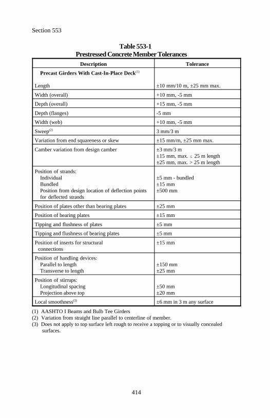
Section 553
414
Table 553-1Prestressed Concrete Member Tolerances
Description Tolerance
Precast Girders With Cast-In-Place Deck(1)
Length ±10 mm/10 m, ±25 mm max.
Width (overall) +10 mm, -5 mm
Depth (overall) +15 mm, -5 mm
Depth (flanges) -5 mm
Width (web) +10 mm, -5 mm
Sweep 3 mm/3 m(2)
Variation from end squareness or skew ±15 mm/m, ±25 mm max.
Camber variation from design camber ±3 mm/3 m±15 mm, max. 25 m length±25 mm, max. > 25 m length
Position of strands:Individual ±5 mm - bundledBundled ±15 mmPosition from design location of deflection points ±500 mmfor deflected strands
Position of plates other than bearing plates ±25 mm
Position of bearing plates ±15 mm
Tipping and flushness of plates ±5 mm
Tipping and flushness of bearing plates ±5 mm
Position of inserts for structural ±15 mm connections
Position of handling devices:Parallel to length ±150 mmTransverse to length ±25 mm
Position of stirrups:Longitudinal spacing ±50 mmProjection above top ±20 mm
Local smoothness ±6 mm in 3 m any surface(3)
(1) AASHTO I Beams and Bulb Tee Girders(2) Variation from straight line parallel to centerline of member.(3) Does not apply to top surface left rough to receive a topping or to visually concealed
surfaces.
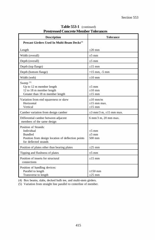
Section 553
415
Table 553-1 (continued)Prestressed Concrete Member Tolerances
Description Tolerance
Precast Girders Used In Multi-Beam Decks(4)
Length ±20 mm
Width (overall) ±5 mm
Depth (overall) ±5 mm
Depth (top flange) ±15 mm
Depth (bottom flange) +15 mm, -5 mm
Width (web) ±10 mm
Sweep (5)
Up to 12 m member length ±5 mm12 to 18 m member length ±10 mmGreater than 18 m member length ±15 mm
Variation from end squareness or skew ±10 mm/mHorizontal ±15 mm max.Vertical ±15 mm
Camber variation from design camber ±3 mm/3 m, ±15 mm max.
Differential camber between adjacent 6 mm/3 m, 20 mm max. members of the same design
Position of Strands:Individual ±5 mmBundled ±5 mmPosition from design location of deflection points 500 mmfor deflected strands
Position of plates other than bearing plates ±25 mm
Tipping and flushness of plates ±5 mm
Position of inserts for structural ±15 mm connections
Position of handling devices:Parallel to length ±150 mmTransverse to length ±25 mm
(4) Box beams, slabs, decked bulb tee, and multi-stem girders.(5) Variation from straight line parallel to centerline of member.
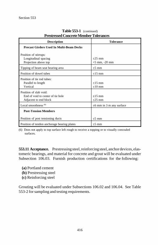
Section 553
416
Table 553-1 (continued)Prestressed Concrete Member Tolerances
Description Tolerance
Precast Girders Used In Multi-Beam Decks
Position of stirrups:Longitudinal spacingProjection above top
±25 mm+5 mm, -20 mm
Tipping of beam seat bearing area ±5 mm
Position of dowel tubes ±15 mm
Position of tie rod tubes:Parallel to length ±15 mmVertical ±10 mm
Position of slab void:End of void to center of tie hole ±15 mmAdjacent to end block ±25 mm
Local smoothness ±6 mm in 3 m any surface(6)
Post-Tension Members
Position of post tensioning ducts ±5 mm
Position of tendon anchorage bearing plates ±5 mm
(6) Does not apply to top surface left rough to receive a topping or to visually concealed surfaces.
553.11 Acceptance. Prestressing steel, reinforcing steel, anchor devices, elas-tomeric bearings, and material for concrete and grout will be evaluated underSubsection 106.03. Furnish production certifications for the following:
(a) Portland cement(b) Prestressing steel(c) Reinforcing steel
Grouting will be evaluated under Subsections 106.02 and 106.04. See Table553-2 for sampling and testing requirements.
Section 553
417
Concrete for precast, prestressed concrete members will be evaluated underSubsections 106.02, 106.03, and 106.04. See Tables 552-7 and 553-2 forsampling and testing requirements.
Concrete for post-tensioned, cast-in-place concrete members will be evaluatedunder Section 552.
Construction of precast, prestressed concrete members and post-tensioned,cast-in-place concrete members will be evaluated under Subsections 106.02and 106.04. Reinforcing steel will be evaluated under Section 554.
Falsework and forms will be evaluated under Section 562.
Measurement
553.12 Measure precast, prestressed structural concrete members by the eachor by the meter. Do not measure reinforcing steel or concrete for precast,structural concrete members.
Measure prestressing system by the lump sum.
Measure the concrete for post-tensioned, cast-in-place concrete structuresunder Section 552. Measure the reinforcing steel for post-tensioned, cast-in-place concrete structures under Section 554.
Measure prestressed piling under Section 551.
Payment
553.13 The accepted quantities, measured as provided above, will be paid atthe contract price per unit of measurement for the pay items listed below thatare shown in the bid schedule. Payment will be full compensation for the workprescribed in this Section. See Subsection 109.05.

Section 553
418
Payment will be made under:
Pay Item Pay Unit
55301 Precast, prestressed concrete structural Each members (description)
55302 Precast, prestressed concrete structural Meter members (description)
55303 Prestressing system Lump sum
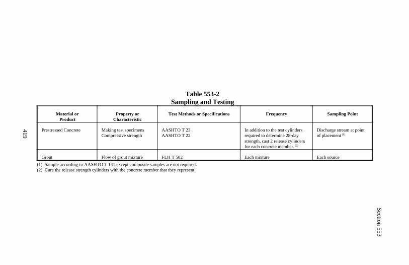
Section 553
419
Table 553-2Sampling and Testing
Material orProduct
Property orCharacteristic
Test Methods or Specifications Frequency Sampling Point
Prestressed Concrete Making test specimensCompressive strength
AASHTO T 23AASHTO T 22
In addition to the test cylindersrequired to determine 28-daystrength, cast 2 release cylindersfor each concrete member. (2)
Discharge stream at pointof placement (1)
Grout Flow of grout mixture FLH T 502 Each mixture Each source(1) Sample according to AASHTO T 141 except composite samples are not required.(2) Cure the release strength cylinders with the concrete member that they represent.
420
Section 554.) REINFORCING STEEL
Description
554.01 This work consists of furnishing and placing reinforcing steel.
Material
554.02 Conform to the following Subsection:
Reinforcing steel 709.01
Construction Requirements
554.03 Order Lists. On reinforcing steel order lists, use the same respectivebar marks for labeling as shown on the plans. Submit all order lists and bend-ing diagrams for acceptance. Acceptance does not relieve the Contractor ofresponsibility for the accuracy of the lists and diagrams. Do not order materialuntil the lists and diagrams are accepted.
Do not fabricate vertical reinforcement in columns, walls, piers, and shafts untilfooting elevations are established in the field.
554.04 Identification. Ship bar reinforcement in standard bundles, taggedand marked according to CRSI Manual of Standard Practice.
554.05 Bending. Fabricate reinforcing bars according to ACI SP 66. Coldbend all reinforcing bars that require bending. Limit the overall height or dropbending tolerance of deck truss bars to plus 0 millimeters or minus 6 millime-ters. Do not bend bars partially embedded in concrete except as shown on theplans or otherwise permitted.
When the dimensions of hooks or the diameter of bends are not shown on theplans, provide standard hooks conforming to ACI SP 66.
554.06 Protection of Material. Store reinforcing steel above the ground onplatforms, skids, or other supports. Protect from physical damage, rust, andother surface deterioration.
Use reinforcing steel only when the surface is clean and the minimumdimensions, cross-sectional area, and tensile properties conform to the physicalrequirements for the size and grade of steel specified.
Section 554
421
Do not use reinforcing steel that is cracked, laminated, or is covered with dirt,rust, loose scale, paint, grease, oil, or other deleterious material.
554.07 Epoxy Coated Reinforcing Steel. Support coated bars on paddedcontact areas. Pad all bundled bands. Lift with a strong back, multiple sup-ports, or a platform bridge. Prevent bar to bar abrasion. Do not drop or dragbundles.
Before placement, inspect coated bars for damage to the coating. Patch alldefects in the coating that are discernable to the unaided eye with a prequalifiedpatching/repair material according to AASHTO M 284M. Clean areas to bepatched by removing all surface contaminants and damaged coating. Roughenthe area to be patched before applying the patching material. Where rust ispresent, remove the rust by blast cleaning or power tool cleaning immediatelybefore applying the patching material.
Promptly treat the bar according to the resin manufacturer's recommendationsand before detrimental oxidation occurs. Overlap the patching material ontothe original coating for 50 millimeters or as recommended by the manufacturer.Provide a minimum 200-micrometer dry film thickness on the patched areas.
Take necessary steps to minimize damage to the epoxy coating of installedbars. Clean and patch any damage to the coating noted after installation asdescribed above.
Field repairs will not be allowed on bars that have severely damaged coatings.Replace bars with severely damaged coatings. A severely damaged coating isdefined as a coating with a total damaged area in any 0.5-meter length of barthat exceeds 5 percent of the surface area of that portion of the bar. Coat me-chanical splices after splice installation according to AASHTO M 284M forpatching damaged epoxy coatings.
554.08 Placing and Fastening. Support the bars on precast concrete blocksor metal supports according to the Manual of Standard Practice of the Con-crete Reinforcing Steel Institute. Attach concrete block supports to the sup-ported bar with wire cast in the center of each block. Use class 1 (plastic pro-tected) or class 2, type B (stainless steel protected) metal supports in contactwith exposed concrete surfaces. Use stainless steel conforming to ASTM A493 type 430.
Section 554
422
Coat chairs, tie wires, and other devices used to support, position, or fastenepoxy coated reinforcement with a dielectric material. Do not use plasticsupports.
Space slab bar supports no more than 1.2 meters apart transversely or longi-tudinally. Do not use bar supports either directly or indirectly to support run-ways for concrete buggies or other similar construction loads.
Space parallel bars within 38 millimeters of the required location. Do notcumulate spacing variations. The average of any two adjacent spaces shall notexceed the required spacing.
Provide 50 millimeters clear cover for all reinforcement except as otherwiseshown on the plans.
Place reinforcing steel in deck slabs within 6 millimeters of the vertical planlocation. Tie bridge deck reinforcing bars together at all intersections exceptwhere spacing is less than 300 millimeters in both directions, in which casealternate intersections may be tied. Check the clear cover over deck reinforc-ing steel using a template before placing deck concrete. Replace damagedsupports.
Tie bundle bars together at intervals not exceeding 2 meters. Do not bundlebars unless the location and splice details are specified.
Do not place concrete in any member until the placement of the reinforcementis approved.
554.09 Splices. Splicing, except as shown on the plans, is not permitted with-out approval. Provide lap lengths shown on the plans. Splice reinforcing barsonly where shown on the plans or accepted drawings. Do not place slab barmechanical splices adjacent to each other.
Make lapped splices by placing the reinforcing bars in contact and wiring themtogether so as to maintain the alignment and position of the bars.
If welding of reinforcing steel is permitted by the contract, the welds shallconform to AWS D 1.4. Do not weld reinforcing steel if the chemical compo-sition of the steel exceeds the percentages in Table 554-1.
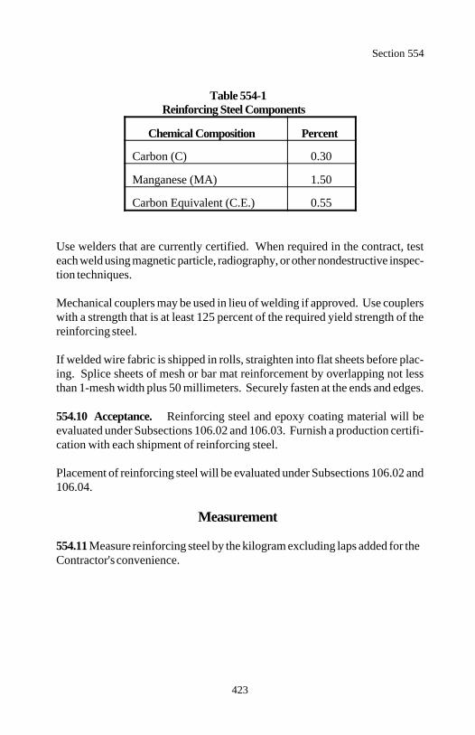
Section 554
423
Table 554-1Reinforcing Steel Components
Chemical Composition Percent
Carbon (C) 0.30
Manganese (MA) 1.50
Carbon Equivalent (C.E.) 0.55
Use welders that are currently certified. When required in the contract, testeach weld using magnetic particle, radiography, or other nondestructive inspec-tion techniques.
Mechanical couplers may be used in lieu of welding if approved. Use couplerswith a strength that is at least 125 percent of the required yield strength of thereinforcing steel.
If welded wire fabric is shipped in rolls, straighten into flat sheets before plac-ing. Splice sheets of mesh or bar mat reinforcement by overlapping not lessthan 1-mesh width plus 50 millimeters. Securely fasten at the ends and edges.
554.10 Acceptance. Reinforcing steel and epoxy coating material will beevaluated under Subsections 106.02 and 106.03. Furnish a production certifi-cation with each shipment of reinforcing steel.
Placement of reinforcing steel will be evaluated under Subsections 106.02 and106.04.
Measurement
554.11 Measure reinforcing steel by the kilogram excluding laps added for theContractor's convenience.

Section 554
424
Payment
554.12 The accepted quantities, measured as provided above, will be paid atthe contract price per unit of measurement for the pay items listed below thatare shown in the bid schedule. Payment will be full compensation for the workprescribed in this Section. See Subsection 109.05.
Payment will be made under:
Pay Item Pay Unit
55401 Reinforcing steel Kilogram55402 Epoxy coated reinforcing steel Kilogram
425
Section 555.) STEEL STRUCTURES
Description
555.01 This work consists of constructing steel structures and the steel struc-ture portions of composite structures. It includes furnishing, fabricating, anderecting structural steels and incidental metal construction.
Material
555.02 Conform to the following Sections and Subsections:
Bearing devices 564Bolts and nuts 717.01(d)Castings 717.04Elastomeric compression joint seals 717.16Falsework 562Galvanized coatings 717.07High-strength bolts, nuts, and washers 717.01(e)Painting 563Pins and rollers 717.03Sheet lead 717.08Steel forgings 717.02Steel grid floors 717.09Steel pipe 717.06Structural steels 717.01Welded stud shear connectors 717.05
Construction Requirements
555.03 General. Fabricate the structural steel in a fabricating plant that iscertified under the AISC Quality Certification Program. Fabricate fracturecritical elements according to the AASHTO Guide Specifications for FractureCritical Non-Redundant Steel Bridge Members.
Perform welding and weld qualification tests according to the provisions ofANSI/AASHTO/AWS Bridge Welding Code D1.5.
555.04 Notice of Beginning of Work. Give written notice 21 days before thebeginning of work at the shop. Do not manufacture any material or performany work in the shop before notification.
Section 555
426
555.05 Inspection. Structural steel may be inspected at the fabrication siteaccording to Subsection 106.06.
Ultrasonically inspect all girder flanges before fabrication according to ASTMA 578M, except as follows:
(a) Inspect after the flanges are stripped from the master plate.
(b) Sections 6 and 7 acceptance standards do not apply. Use supplementaryrequirement S2.1 for acceptance standards.
(c) Flanges may be inspected in the plant or warehouse where the flanges arestripped.
Furnish a copy of all mill orders and certified mill test reports. Show on themill test reports the chemical analyses and physical test results for each heat ofsteel used in the work.
If approved, furnish production certifications, in lieu of mill test reports formaterial that normally is not supplied with mill test reports and for items suchas fills, minor gusset plates, and similar material when quantities are small andthe material is taken from stock.
Include in the certified mill test reports for steels with specified impact values,in addition to other test results, the results of Charpy V-notch impact tests.When fine-grain practice is specified, confirm on the test report that the mate-rial was so produced. Furnish copies of mill orders at the time orders areplaced with the manufacturer. Furnish certified mill test reports and productioncertifications before the start of fabrication using material covered by thesereports. Furnish, from the manufacturer, a production certification accordingto Subsection 106.03.
555.06 Drawings (Shop Drawings, Erection Drawings, and Transporta-tion Drawings). Prepare and submit drawings according to Subsection104.03. Acceptance of the drawings covers the requirements for strength anddetail only. No responsibility is assumed for errors in dimensions.
(a) Shop drawings. Show full, detailed dimensions and sizes of componentparts of the structure and details of all miscellaneous parts (such as pins, nuts,bolts, drains, weld symbols, etc.) on shop drawings for steel structures.
Section 555
427
Where specific orientation of plates is required, show the direction of rollingof plates. Cut flanges and webs of plate girders from plates so the long di-mension of the girder parallels the rolling direction.
Identify on the shop drawings the type and grade of each piece that is to bemade of steel other than AASHTO M 270M grade 250 steel.
Show on the shop drawings assembly marks that are cross-referenced to theoriginal pieces of mill steel and their certified mill test reports.
The location of all shop welded splices shown on the shop drawings aresubject to approval. Locate all shop welded splices to avoid points of maxi-mum tensile or fatigue stress. Locate splices in webs at least 300 millimetersfrom shop splices, butt joints in flanges, or stiffeners. Additional nondestruc-tive tests may be required on shop welded splices.
(b) Erection drawings. Submit drawings fully illustrating the proposedmethod of erection. Show details of all falsework bents, bracing, guys,dead-men, lifting devices, and attachments to the bridge members. Show thesequence of erection, location of cranes and barges, crane capacities, locationof lifting points, and masses of bridge members. Show complete details forall anticipated phases and conditions of erection. Calculations may be re-quired to demonstrate that allowable stresses are not exceeded and that mem-ber capacities and final geometry will be correct. See Subsection 562.03 foradditional requirements.
(c) Camber diagram. Furnish a camber diagram that shows the camber ateach panel point of trusses or arch ribs and at the location of field splices andfractions of span length (quarter points minimum) of continuous beams andgirders or rigid frames. On the camber diagram, show calculated cambers tobe used in preassembly of the structure as required in Subsection 555.15.
(d) Transportation drawings. Show all support points, tie-downs, tem-porary stiffening trusses or beams, and any other details needed to supportand brace the member. Provide calculation sheets showing dead load plusimpact stresses induced by the loading and transportation procedure. Useimpact stresses of at least 200 percent of the dead load stress. Use a totalload, including impact, of not less than 300 percent of the dead load.
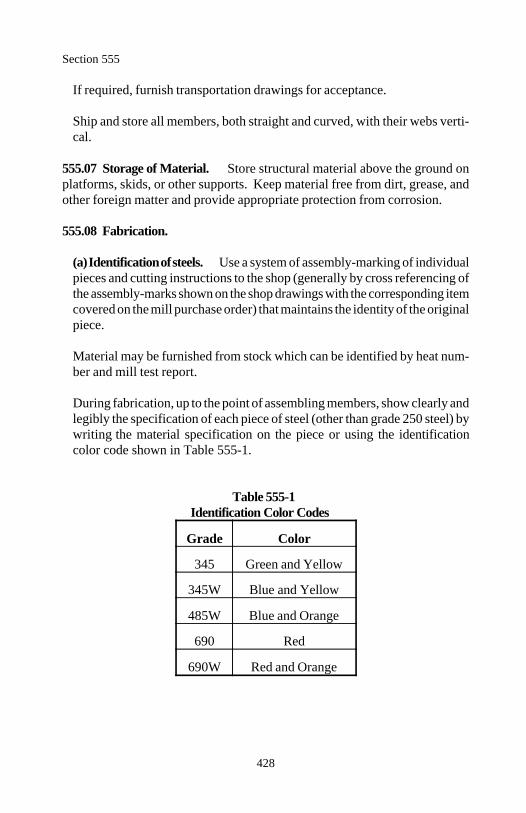
Section 555
428
If required, furnish transportation drawings for acceptance.
Ship and store all members, both straight and curved, with their webs verti-cal.
555.07 Storage of Material. Store structural material above the ground onplatforms, skids, or other supports. Keep material free from dirt, grease, andother foreign matter and provide appropriate protection from corrosion.
555.08 Fabrication.
(a) Identification of steels. Use a system of assembly-marking of individualpieces and cutting instructions to the shop (generally by cross referencing ofthe assembly-marks shown on the shop drawings with the corresponding itemcovered on the mill purchase order) that maintains the identity of the originalpiece.
Material may be furnished from stock which can be identified by heat num-ber and mill test report.
During fabrication, up to the point of assembling members, show clearly andlegibly the specification of each piece of steel (other than grade 250 steel) bywriting the material specification on the piece or using the identificationcolor code shown in Table 555-1.
Table 555-1Identification Color Codes
Grade Color
345 Green and Yellow
345W Blue and Yellow
485W Blue and Orange
690 Red
690W Red and Orange
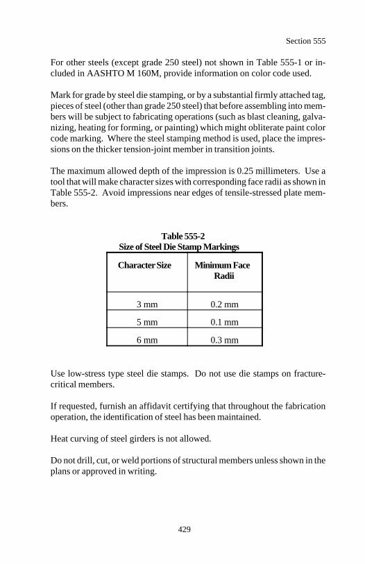
Section 555
429
For other steels (except grade 250 steel) not shown in Table 555-1 or in-cluded in AASHTO M 160M, provide information on color code used.
Mark for grade by steel die stamping, or by a substantial firmly attached tag,pieces of steel (other than grade 250 steel) that before assembling into mem-bers will be subject to fabricating operations (such as blast cleaning, galva-nizing, heating for forming, or painting) which might obliterate paint colorcode marking. Where the steel stamping method is used, place the impres-sions on the thicker tension-joint member in transition joints.
The maximum allowed depth of the impression is 0.25 millimeters. Use atool that will make character sizes with corresponding face radii as shown inTable 555-2. Avoid impressions near edges of tensile-stressed plate mem-bers.
Table 555-2Size of Steel Die Stamp Markings
Character Size Minimum FaceRadii
3 mm 0.2 mm
5 mm 0.1 mm
6 mm 0.3 mm
Use low-stress type steel die stamps. Do not use die stamps on fracture-critical members.
If requested, furnish an affidavit certifying that throughout the fabricationoperation, the identification of steel has been maintained.
Heat curving of steel girders is not allowed.
Do not drill, cut, or weld portions of structural members unless shown in theplans or approved in writing.
Section 555
430
(b) Plates.
(1) Direction of rolling. Unless otherwise shown on the drawings, cutand fabricate steel plates for main members and splice plates for flangesand main tension members, not secondary members, so that the primarydirection of rolling is parallel to the direction of the principal tensileand/or compressive stresses.
(2) Plate cut edges.
(a) Edge planing. Remove sheared edges on plates thicker than 15millimeters to a depth of 5 millimeters beyond the original shearededge, or beyond any re-entrant cut produced by shearing. Fillet re-entrant cuts before cutting.
(1) Oxygen cutting. Oxygen cut structural steel according to ANSI/AASHTO/AWS Bridge Welding Code D1.5.
(2) Visual inspection and repair of plate cut edges. Visually in-spect and repair plate cut edges. The cut edges shall conform toANSI/AASHTO/AWS Bridge Welding Code D1.5.
(b) Flange plates. Furnish flange plates with either oxygen cut edgesthat have the corners chamfered at least 2 millimeters by grinding orfurnish Universal Mill plates unless oxygen cut edges are required.
(c) Web plates. Oxygen cut to the prescribed camber web plates ofbuilt-up beams and girders, box girders, and box arches. Cut sufficientextra camber into the webs to provide for all camber losses due towelding, cutting, etc.
(d) Truss members. Prepare, by oxygen cutting, all longitudinal edgesof all plates in welded sections of truss web and chord members.Chamfer, by grinding the edges of the corners of plates not joined bywelding, at least 2 millimeters.

Section 555
431
(e) Stiffeners and connection plates. Stiffeners and connection plateswelded transverse to girder webs and flanges may be furnished withsheared edges provided the plate thickness does not exceed 20 milli-meters. Universal mill plate may be used provided its thickness doesnot exceed 25 millimeters. Furnish other stiffeners and connectionplates with oxygen cut edges.
(f) Lateral gusset plates. Oxygen cut, parallel to lines of stress, gussetplates and other connections welded parallel to lines of stress in ten-sion members where the plate thickness exceeds 10 millimeters.Bolted lateral gusset plates may be furnished with sheared edges pro-vided the thickness is less than or equal to 20 millimeters.
(g) Splice plates and gusset plates. Furnish girder and stringer spliceplates and truss gusset plates with oxygen cut edges.
(h) Bent plates. Furnish unwelded, load-carrying, rolled-steel platesto be bent as follows.
Take material from the stock plates such that the bend line will be atright angles to the direction of rolling, except that cold-bent ribs fororthotopic-deck bridges may be bent with bend lines in the directionof rolling.
Before bending, round the corners of the plates to a radius of 2 milli-meters throughout the portion of the plate where the bending occurs.
(1) Cold bending. Cold bend so that no cracking of the plate oc-curs. Use the minimum bend radii shown in Table 555-3 measuredto the concave face of the metal.
Allow for springback of grades 690 and 690W steels equal toabout three times that for grade 250 steel. Use a lower die span ofat least 16 times the plate thickness for break press forming.
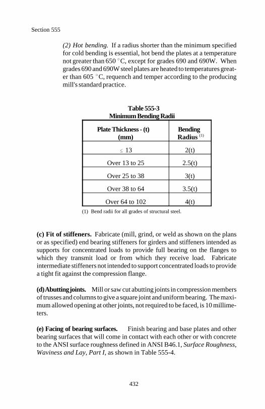
Section 555
432
(2) Hot bending. If a radius shorter than the minimum specifiedfor cold bending is essential, hot bend the plates at a temperaturenot greater than 650 C, except for grades 690 and 690W. Whengrades 690 and 690W steel plates are heated to temperatures great-er than 605 C, requench and temper according to the producingmill's standard practice.
Table 555-3Minimum Bending Radii
Plate Thickness - (t) Bending(mm) Radius (1)
13 2(t)
Over 13 to 25 2.5(t)
Over 25 to 38 3(t)
Over 38 to 64 3.5(t)
Over 64 to 102 4(t) (1) Bend radii for all grades of structural steel.
(c) Fit of stiffeners. Fabricate (mill, grind, or weld as shown on the plansor as specified) end bearing stiffeners for girders and stiffeners intended assupports for concentrated loads to provide full bearing on the flanges towhich they transmit load or from which they receive load. Fabricateintermediate stiffeners not intended to support concentrated loads to providea tight fit against the compression flange.
(d) Abutting joints. Mill or saw cut abutting joints in compression membersof trusses and columns to give a square joint and uniform bearing. The maxi-mum allowed opening at other joints, not required to be faced, is 10 millime-ters.
(e) Facing of bearing surfaces. Finish bearing and base plates and otherbearing surfaces that will come in contact with each other or with concreteto the ANSI surface roughness defined in ANSI B46.1, Surface Roughness,Waviness and Lay, Part I, as shown in Table 555-4.
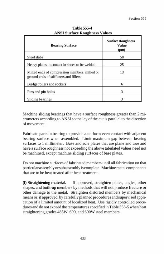
Section 555
433
Table 555-4ANSI Surface Roughness Values
Bearing Surface ValueSurface Roughness
(µm)
Steel slabs 50
Heavy plates in contact in shoes to be welded 25
Milled ends of compression members, milled or 13ground ends of stiffeners and fillers
Bridge rollers and rockers 6
Pins and pin holes 3
Sliding bearings 3
Machine sliding bearings that have a surface roughness greater than 2 mi-crometers according to ANSI so the lay of the cut is parallel to the directionof movement.
Fabricate parts in bearing to provide a uniform even contact with adjacentbearing surface when assembled. Limit maximum gap between bearingsurfaces to 1 millimeter. Base and sole plates that are plane and true andhave a surface roughness not exceeding the above tabulated values need notbe machined, except machine sliding surfaces of base plates.
Do not machine surfaces of fabricated members until all fabrication on thatparticular assembly or subassembly is complete. Machine metal componentsthat are to be heat treated after heat treatment.
(f) Straightening material. If approved, straighten plates, angles, othershapes, and built-up members by methods that will not produce fracture orother damage to the metal. Straighten distorted members by mechanicalmeans or, if approved, by carefully planned procedures and supervised appli-cation of a limited amount of localized heat. Use rigidly controlled proce-dures and do not exceed the temperatures specified in Table 555-5 when heatstraightening grades 485W, 690, and 690W steel members.
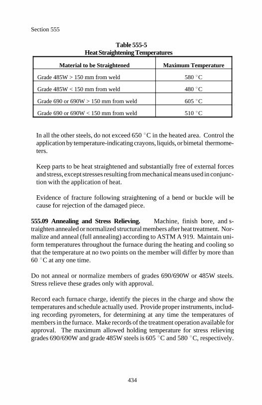
Section 555
434
Table 555-5Heat Straightening Temperatures
Material to be Straightened Maximum Temperature
Grade 485W > 150 mm from weld 580 C
Grade 485W < 150 mm from weld 480 C
Grade 690 or 690W > 150 mm from weld 605 C
Grade 690 or 690W < 150 mm from weld 510 C
In all the other steels, do not exceed 650 C in the heated area. Control theapplication by temperature-indicating crayons, liquids, or bimetal thermome-ters.
Keep parts to be heat straightened and substantially free of external forcesand stress, except stresses resulting from mechanical means used in conjunc-tion with the application of heat.
Evidence of fracture following straightening of a bend or buckle will because for rejection of the damaged piece.
555.09 Annealing and Stress Relieving. Machine, finish bore, and s-traighten annealed or normalized structural members after heat treatment. Nor-malize and anneal (full annealing) according to ASTM A 919. Maintain uni-form temperatures throughout the furnace during the heating and cooling sothat the temperature at no two points on the member will differ by more than60 C at any one time.
Do not anneal or normalize members of grades 690/690W or 485W steels.Stress relieve these grades only with approval.
Record each furnace charge, identify the pieces in the charge and show thetemperatures and schedule actually used. Provide proper instruments, includ-ing recording pyrometers, for determining at any time the temperatures ofmembers in the furnace. Make records of the treatment operation available forapproval. The maximum allowed holding temperature for stress relievinggrades 690/690W and grade 485W steels is 605 C and 580 C, respectively.
Section 555
435
Stress relieve members (such as bridge shoes, pedestals, or other parts that arebuilt up by welding sections of plate together) according to Subsection 4.4 ofANSI/AASHTO/AWS Bridge Welding Code D1.5.
555.10 Bolt Holes. Punch or drill all bolt holes. Material forming the partsof a member that is composed of not more than 5 thicknesses of metal may bepunched 2 millimeters larger than the nominal diameter of the bolts where thethickness of the material is not greater than 20 millimeters for structural steel,15 millimeters for high-strength steel, or 15 millimeters for quenched and tem-pered alloy steel, unless subpunching and reaming is required under (h), thepreparation of field connections.
Where there are more than five thicknesses or where any of the main materialis thicker than 20 millimeters for structural steel, 15 millimeters forhigh-strength steel, or 15 millimeters for quenched and tempered alloy steel,either subdrill and ream or drill all holes full size.
If required, either subpunch or subdrill (subdrill if thickness limitation governs)5 millimeters smaller and, after assembling, ream 2 millimeters larger or drillfull size to 2 millimeters larger than the nominal diameter of the bolts.
(a) Punched holes. Use a die diameter that is not more than 2 millimeterslarger than the punch diameter. Ream holes that require enlarging to admitbolts. Clean cut the holes without torn or ragged edges.
(b) Reamed or drilled holes. Ream or drill holes so they are cylindrical andperpendicular to the member. Where practical, direct reamers by mechanicalmeans. Remove burrs on the outside surfaces. Ream and drill with twistdrills, twist reamers, or roto-broach cutters. Assemble and securely hold to-gether connecting parts that are being reamed or drilled and match-markbefore disassembling.
(c) Accuracy of holes. Holes not more than 1 millimeter larger in diameterthan the true decimal equivalent of the nominal diameter of the drill orreamer are acceptable. The slightly conical hole resulting from punchingoperations is acceptable. The width of slotted holes produced by flamecutting or a combination of drilling or punching and flame cutting shall be nomore than 1 millimeter greater than the nominal width. Grind flame cutsurfaces smooth.
Section 555
436
(d) Accuracy of hole group before reaming. Accurately punch full size,subpunched, or subdrilled holes so that after assembling (before any reamingis done) a cylindrical pin 3 millimeters smaller in diameter than the nominalsize of the punched hole may be entered perpendicular to the face of themember, without drifting, in at least 75 percent of the contiguous holes in thesame plane. Punched pieces not meeting this requirement will be rejected.Holes, through which a pin 5 millimeters smaller in diameter than thenominal size of the punched hole cannot be inserted, will be rejected.
(e) Accuracy of hole group after reaming. After reaming, the maximumallowed offset of 85 percent of any contiguous group of holes throughadjacent thicknesses of metal is 1 millimeter.
Use steel templates having hardened steel bushings in holes accurately dime-nsioned from the centerlines of the connection as inscribed on the template.Use connection centerlines when locating templates from the milled orscribed ends of members.
(f) Numerically-controlled drilled field connections. In lieu of drillingundersized holes and reaming while assembled, or drilling holes full-sizewhile assembled, drilling or punching bolt holes full-size in unassembledpieces and/or connections, including templates for use with matchingundersized and reamed holes by means of suitable numerically-controlled(N/C) drilling or punching equipment is allowed.
(g) Holes for ribbed bolts, turned bolts, or other approved bearing-typebolts. Provide finished holes with a driving fit.
(h) Preparation of field connections. Subpunch or subdrill and ream whileassembled, or drill full size to a steel template, the holes in field connectionsand field splices of main members of trusses, arches, continuous beam spans,bents, towers (each face), plate girders, and rigid frames.
Holes for field splices of rolled beam stringers continuous over floor beamsor cross frames may be drilled full-size unassembled to a steel template.Holes for floor beams or cross frames may be drilled full size unassembledto a steel template. Subpunch and ream while assembled, or drill full size toa steel template, all holes for floor beam and stringer field end connections.
Section 555
437
When reaming or drilling full size field connection holes through a steeltemplate, carefully locate and position the template and firmly bolt in place,before drilling. Use exact duplicates of templates used for reaming matchingmembers, or the opposite faces of a single member. Accurately locatetemplates used for connections on like parts or members so that the parts ormembers are duplicates and require no match-marking.
For any connection, in lieu of subpunching and reaming or subdrilling andreaming, holes drilled full size through all thicknesses or material assembledin proper position may be used.
555.11 Pins and Rollers. Accurately fabricate pins and rollers that arestraight, smooth, and free from flaws. Forge and anneal pins and rollers morethan 225 millimeters in diameter. Pins and rollers 225 millimeters or less indiameter may be either forged and annealed or cold-finished carbonsteelshafting.
In pins larger than 225 millimeters in diameter, bore a hole not less than 50millimeters in diameter full length along the pin axis after the forging has beenallowed to cool to a temperature below the critical range (under suitableconditions to prevent damage by too rapid cooling and before being annealed).
(a) Boring pin holes. Bore pin holes true to the specified diameter, smoothand straight, at right angles with the axis of the member and parallel witheach other. Produce the final surface using a finishing cut.
Produce a pin hole diameter that does not exceed that of the pin by more than0.50 millimeter for pins 125 millimeters or less in diameter, or by 1millimeter for larger pins.
The maximum allowed variation of the outside-to-outside distance of endholes in tension members and the inside-to-inside distance of end holes incompression members is 1 millimeter from that specified. Bore pin holes inbuilt-up members after the member has been assembled.
(b) Threads for bolts and pins. Provide threads on all bolts and pins forstructural steel construction that conform to the Unified Standard SeriesUNC ANSI B1.1, class 2A for external threads and class 2B for internalthreads, except when pin ends have a diameter of 35 millimeters or more,provide six threads per 25 millimeters.
Section 555
438
555.12 Eyebars. Pin holes may be flame cut at least 50 millimeters smallerin diameter than the finished pin diameter. Securely fasten together (in theorder to be placed on the pin) all eyebars that are to be placed side by side inthe structure and bore at both ends while clamped. Pack and match-markeyebars for shipment and erection. Stamp with steel stencils, so as to be visiblewhen the bars are nested in place on the structure, all identifying marks on theedge of one head of each member after fabrication is completed. Use low-stress type steel die stamps.
Provide eyebars, straight and free from twists, with pin holes accurately locatedon the centerline of the bar. Do not allow the inclination of any bar to theplane of the truss to exceed 5.25 millimeters per meter.
Simultaneously cut the edges of eyebars that lie between the transversecenterline of their pin holes with two mechanically operated torches abreast ofeach other, guided by a substantial template to prevent distortion of the plates.
555.13 Assembly - Bolting. Clean surfaces of metal in contact beforeassembling. Assemble parts of a member. Securely pin and firmly drawtogether before drilling, reaming, or bolting is commenced. Take assembledpieces apart, if necessary, for the removal of burrs and shavings produced bythe operation. Assemble members to be free from twists, bends, and otherdeformation.
Drift during assembling only enough to bring the parts into position withoutenlarging holes or distorting the metal.
555.14 Welded Connections. Fabricate surfaces and edges to be weldedsmooth, uniform, clean, and free of defects that would adversely affect thequality of the weld. Prepare edge according to ANSI/AASHTO/AWS BridgeWelding Code D1.5.
555.15 Preassembly of Field Connections. Preassemble field connectionsof main members of trusses, arches, continuous beams, plate girders, bents,towers, and rigid frames before erection to verify the geometry of the com-pleted structure or unit and to verify or prepare field splices. Present themethod and details of preassembly for approval.
Section 555
439
Use methods and details of preassembly that are consistent with the procedureshown on the approved erection camber diagrams. Assemble all girders andbeams in their cambered (no load) condition.
When members are assembled with their webs vertical, support them atintervals of 6 meters, or two tenths of the span length, whichever is less. Whenthe webs are horizontal, the above intervals of support may be increasedprovided there is no noticeable deflection between points of support.
Assemble trusses in full dead-load position unless the design of the structureprovides for the secondary stresses created by assembling the truss in the fullycambered (no load) position. Support trusses during assembly at each panelpoint. Preassemble at least 3 contiguous panels that are accurately adjusted forline and camber. For successive assemblies include at least one section orpanel of the previous assembly (repositioned if necessary and adequatelypinned to assure accurate alignment) plus 2 or more sections or panels addedat the advancing end. For structures longer than 50 meters, make each assem-bly not less than 50 meters long regardless of the length of individual continu-ous panels or sections. Assembly may start from any location in the structureand proceed in one or both directions as long as preceding requirements aresatisfied.
(a) Bolted connections. Where applicable, assemble major componentswith milled ends of compression members in full bearing and then reamsubsized holes to the specified size while the connections are assembled.
(b) Check assembly/numerically-controlled drilling. When using numeri-cally controlled drilling or punching, make a check assembly for each majorstructural type of each project. Fabricate the check assembly of at least 3contiguous shop sections or, for a truss, all members in at least 3 contiguouspanels but not less than the number of panels associated with 3 contiguouschord lengths (such as the length between field splices). Base checkassemblies on the proposed order of erection, joints in bearings, specialcomplex points, and similar considerations. Shop assemblies other than thecheck assemblies are not required.
If the check assembly fails in some specific manner to demonstrate that therequired accuracy is being obtained, further check assemblies may be re-quired.
Section 555
440
Receive approval of each assembly (including camber, alignment, accuracyof holes, and fit of milled joints) before reaming is commenced or before anyN/C drilled check assembly is dismantled.
(c) Field welded connections. Field welded connections are prohibitedunless specifically shown on the drawings. Verify the fit of members (in-cluding the proper space between abutting flanges) with the segment preas-sembled.
(d) Match marking. Match mark connecting parts preassembled in the shopto assure proper fit in the field. Provide a diagram showing such match-marks.
555.16 Connections Using Unfinished, Turned, or Ribbed Bolts. Useunfinished, turned, or ribbed bolts, where specified, conforming to ASTM A307 for grade A bolts. Use bolts with single self-locking nuts or double nuts.Use beveled washers where bearing faces have a slope of more than 1:20 withrespect to a plane normal to the bolt axis.
(a) Turned bolts. Furnish turned bolts with a body surface ANSI roughnessnot exceeding 3 micrometers. Furnish hex headed bolts and nuts of thenominal size specified. Carefully ream holes for turned bolts and furnishbolts to provide for a light driving fit. Keep bolt threads entirely outside ofthe holes. Provide a washer under the nut.
(b) Ribbed bolts. Use approved form of ribbed body with continuouslongitudinal ribs. Provide a body diameter measured on a circle through thepoints of the ribs 2 millimeters greater than the nominal diameter specifiedfor the bolts.
Furnish ribbed bolts with round heads conforming to ANSI B18.5. Furnishhexagonal nuts that are either recessed or have a washer of suitable thickness.Ribbed bolts shall have a driving fit when installed in holes. Providesufficiently hard ribs such that the ribs do not compress or deform and allowthe bolts to turn in the holes during tightening. If the bolt twists beforedrawing tight, ream the hole and provide an oversized replacement bolt.
Section 555
441
555.17 Connections Using High-Strength Bolts. This subsection coversthe assembly of structural joints using AASHTO M 164M or AASHTOM 253M high-strength bolts, or equivalent fasteners, tightened to a high ten-sion.
(a) Bolted parts. Use steel material within the grip of the bolt with nocompressible material such as gaskets or insulation. Fabricate bolted steelparts to fit solidly together after the bolts are tightened. Limit the maximumslope of the surfaces of parts in contact with the bolt head or nut to 1:20 withrespect to a plane normal to the bolt axis.
(b) Surface conditions. At the time of assembly clean all joint surfaces(including surfaces adjacent to the bolt head and nut) of dirt or foreignmaterial and scale, except tight mill scale. Remove burrs that would preventsolid seating of the connected parts in the snug-tight condition.
Paint or other coatings are not permitted on the faying surfaces of slip-criticalconnections. All connections are considered to be slip-critical. Excludepaint (including any inadvertent overspray) from areas closer than one-boltdiameter, but not less than 25 millimeters, from the edge of any hole and allareas within the bolt pattern.
(c) Installation. Install fasteners of the same lot number together. Protectfasteners from dirt and moisture. Take from protected storage only as manyfasteners as are anticipated to be installed and tightened during a work shift.Return to protected storage fasteners not used at the end of the shift. Do notclean lubricant from fasteners that is required to be present in the as-delivered condition. Clean and relubricate, before installation, fasteners forslip-critical connections which accumulate rust or dirt.
Provide a tension measuring device (a Skidmore-Wilhelm calibrator or otheracceptable bolt tension indicating device) on all projects where high- strengthfasteners are being installed and tightened. Use the tension measuring deviceto perform the rotational-capacity test and to confirm all of the following:
Table 555-6 requirement for the complete fastener assembly Calibration of the wrenches, if applicable Understanding and proper use of the tightening method
Section 555
442
Table 555-6Minimum Fastener Tension (1)
Nominal Bolt AASHTO M 164M AASHTO M 253MDiameter and (kilonewtons) (kilonewtons)Tread Pitch
M16 × 2 91 114M20 × 2.5 142 179M22 × 2.5 176 221M24 × 3 205 257M27 × 3 267 334M30 × 3.5 326 408M36 × 4 475 595
(1) Equal to 70 percent of the specified minimum tensile strength of bolts (asspecified for tests of full size ASTM A 325M and ASTM A 490M bolts) roundedto the nearest kilonewton.
For short grip bolts, direct tension indicators (DTI) with solid plates may beused to perform this test. First check the DTI with a longer grip bolt in theSkidmore-Wilhelm calibrator. The frequency of confirmation testing,number of tests to be performed, and test procedure shall conform to (3)through (5) as applicable. Confirm the accuracy of the tension measuringdevice by an approved testing agency at least annually.
Install fasteners together with washers of size and quality specified, locatedas required below, in properly aligned holes and tightened by any of themethods described in (3) to (6) inclusive to at least the minimum tensionspecified in Table 555-6 after all the fasteners are tight.
If approved, tightening may be performed by turning the bolt while the nutis prevented from rotating when it is impractical to turn the nut. If impactwrenches are used, provide adequate capacity and sufficient air to tighteneach bolt in approximately 10 seconds.
Do not reuse AASHTO M 253M fasteners and galvanized AASHTO M164M fasteners. If approved, other AASHTO M 164M bolts may be re-usedonce. Touching up or retightening previously tightened bolts that may havebeen loosened by the tightening of adjacent bolts will not be considered asreuse, provided the snugging up continues from the initial position and doesnot require greater rotation, including the tolerance, than that required byTable 555-7.
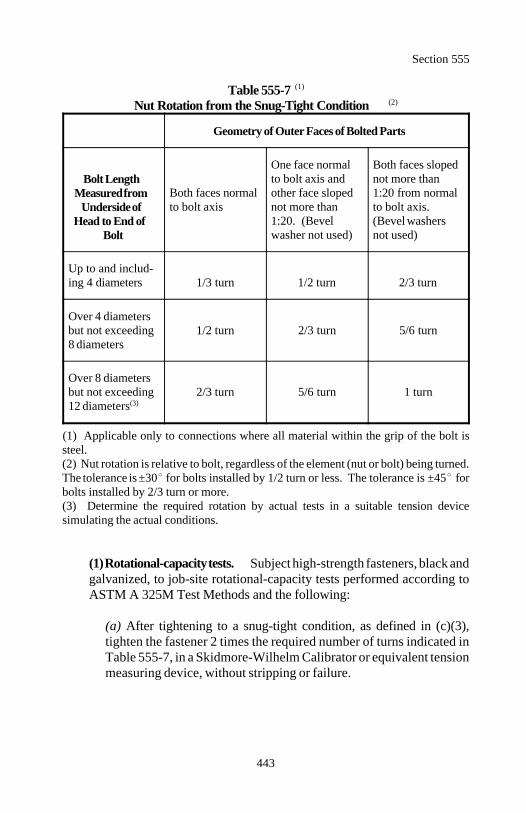
Section 555
443
Table 555-7 (1)
Nut Rotation from the Snug-Tight Condition (2)
Geometry of Outer Faces of Bolted Parts
Bolt LengthMeasured from
Underside ofHead to End of
Bolt
Both faces normal other face sloped 1:20 from normalto bolt axis not more than to bolt axis.
One face normal Both faces slopedto bolt axis and not more than
1:20. (Bevel (Bevel washerswasher not used) not used)
Up to and includ-ing 4 diameters 1/3 turn 1/2 turn 2/3 turn
Over 4 diametersbut not exceeding 1/2 turn 2/3 turn 5/6 turn8 diameters
Over 8 diametersbut not exceeding 2/3 turn 5/6 turn 1 turn12 diameters(3)
(1) Applicable only to connections where all material within the grip of the bolt issteel.(2) Nut rotation is relative to bolt, regardless of the element (nut or bolt) being turned.The tolerance is ±30 for bolts installed by 1/2 turn or less. The tolerance is ±45 forbolts installed by 2/3 turn or more. (3) Determine the required rotation by actual tests in a suitable tension devicesimulating the actual conditions.
(1) Rotational-capacity tests. Subject high-strength fasteners, black andgalvanized, to job-site rotational-capacity tests performed according toASTM A 325M Test Methods and the following:
(a) After tightening to a snug-tight condition, as defined in (c)(3),tighten the fastener 2 times the required number of turns indicated inTable 555-7, in a Skidmore-Wilhelm Calibrator or equivalent tensionmeasuring device, without stripping or failure.
Torque PD4000
Section 555
444
(b) During this test, the maximum recorded tension must be equal toor greater than the turn test tension which is 1.15 times the requiredfastener tension indicated in Table 555-6.
(c) The measured torque at a tension "P," after exceeding the turn testtension required above in (b), shall not exceed the value obtained bythe following equation:
Where:
Torque = Measured torque in newton metersP = Measured bolt tension in newtonsD = Nominal bolt diameter in millimeters
For rotational-capacity tests, use washers even though their use maynot be required in the actual installation.
(2) Washers. Where the outer face of the bolted parts has a slope greaterthan 1:20 with respect to a plane normal to the bolt axis, use a hardenedbevelled washer to compensate for the lack of parallelism.
Use hardened square or rectangular beveled washers for American Stan-dard Beams and Channels conforming to AASHTO M 293.
Where necessary, washers may be clipped on one side not closer than 7/8of the bolt diameter from the center of the washer.
Hardened washers are not required for connections using AASHTO M164M and AASHTO M 253M bolts except under the following condi-tions.
(a) Use hardened washers under the element turned in tightening whenthe tightening is done by the calibrated wrench method.
Section 555
445
(b) Use hardened washers under both the head and the nut whenAASHTO M 253M bolts are installed in material having a specifiedyield point less than 275 megapascals regardless of the tighteningmethod.
(c) Use a hardened washer conforming to ASTM F 436M whereAASHTO M 164M bolts of any diameter or AASHTO M 253M boltsequal to or less than M24 are to be installed in oversize or short-slottedholes in an outer ply.
(d) Use hardened washers conforming to ASTM F 436M, except with8 millimeter minimum thickness, under both the head and the nut inlieu of standard thickness hardened washers where AASHTO M 253Mbolts over M24 are to be installed in an oversize or shortslotted holein an outer ply. Multiple hardened washers with a combined thicknessequal to or greater than 8 millimeters do not satisfy this requirement.
(e) Where AASHTO M 164M bolts of any diameter or AASHTO M253M bolts equal to or less than M24 are installed in a long-slottedhole in an outer ply, provide a plate washer or continuous bar of atleast 8-millimeter thickness with standard holes with sufficient size tocover the slot after installation and is structural grade material thatneed not be hardened.
When AASHTO M 253M bolts over M24 are used in long-slottedholes in external plies, use a single hardened washer conforming toASTM F 436M with an 8-millimeter minimum thickness in lieu ofwashers or bars of structural grade material. Multiple hardened wash-ers with combined thickness equal to or greater than 8 millimeters donot satisfy this requirement.
Alternate design fasteners conforming to Subsection 717.01 with ageometry that provides a bearing circle on the head or nut with adiameter equal to or greater than the diameter of hardened washersconforming to ASTM F 436M satisfy the requirements for washersspecified herein and may be used without washers.
Section 555
446
(3) Turn-of-nut tightening. At the start of work, test nut tighteningusing a device capable of indicating bolt tension. Test not less than 3bolt-and-nut assemblies of each diameter, length, and grade to be used inthe work. Demonstrate with the test that the method for estimating snug-tight condition and controlling the turns from snug tight develops atension not less than 5 percent greater than the tension required by Table555-6. Perform periodic retesting when required.
Install bolts in all holes of the connection and initially tighten to a snug-tight condition. Snug tight is defined as the tightness that exists when theplies of the joint are in firm contact. This may be attained by a fewimpacts of an impact wrench or the full effort of a worker using an ordi-nary spud wrench.
Systematically snug-tighten bolt groups from the most rigid part of theconnection to the free edges. Then retighten the bolts of the connectionin a similar systematic manner as necessary until all bolts are snug tightand the connection is fully compacted. Following the snug-tighteningoperation, tighten all bolts in the connection by the applicable amount ofrotation specified in Table 555-7.
During all tightening operations, do not allow rotation of the fastener partnot turned by the wrench. Tighten systematically from the most rigid partof the joint to its free edges.
(4) Calibrated wrench tightening. Calibrated wrench tightening may beused only when installation procedures are calibrated on a daily basis andwhen a hardened washer is used under the element turned in tightening.Standard torques taken from tables or from formulas that assume to relatetorque to tension are not acceptable.
If calibrated wrenches are used for installation, set them to provide atension not less than 5 percent in excess of the minimum tension specifiedin Table 555-6. Calibrate the installation procedure at least once eachworking day for each bolt diameter, length, and grade using fastenerassemblies that are being installed in the work.
Section 555
447
Perform the calibration with a device capable of indicating actual bolt ten-sion by tightening 3 typical bolts of each diameter, length, and grade fromthe bolts and washers being installed using a job-supplied washer underthe element turned in tightening. Recalibrate wrenches when significantdifference is noted in the surface condition of the bolts, threads, nuts orwashers. Verify during use that the wrench adjustment selected by thecalibration does not produce a nut or bolt head rotation from snug tightgreater than permitted in Table 555-7. Turn nuts in the tighteningdirection when measuring the torque of manual torque wrenches.
If calibrated wrenches are used to install bolts in a connection, installbolts with hardened washers under the turned element. When tighteningbolts in all holes of the connection, tighten to a snug-tight condition.Following this initial tightening operation, tighten all bolts in theconnection using a calibrated wrench. Tighten systematically from themost rigid part of the joint to its free edges. Touch up previouslytightened bolts that may have been relaxed during the tightening ofadjacent bolts until all bolts are properly tightened.
(5) Direct tension indicator tightening. When tightening of bolts usingdirect tension indicator devices is used, assemble a representative sampleof not less than 3 devices for each diameter and grade of fastener to beused in the work in a calibration device capable of indicating bolt tension.Include in the test assembly flat-hardened washers, if required in theactual connection, arranged as those in the actual connections to betensioned. The calibration test must demonstrate that the device indicatesa tension not less than 5 percent greater than that required by Table 555-6.
Follow the manufacturer's installation procedures for installation of boltsin the calibration device and in all connections. Give special attention toproper installation of flat-hardened washers when direct tension indicatordevices are used with bolts installed in oversize or slotted holes and wherethe load indicating devices are used under the turned element.
Section 555
448
When bolts are installed using direct tension indicators conforming toASTM F 959, install bolts in all holes of the connection and bring to asnug-tight condition. Snug tight is indicated by partial compression of thedirect tension indicator protrusions. Then tighten all fasteners systemati-cally from the most rigid part of the connection to the free edges in amanner that will minimize relaxation of previously tightened fasteners. Proper tensioning of the bolts may require more than a single cycle ofsystematic partial tightening before final tightening to deform the protru-sion to the specified gap.
(6) Installation of alternate design bolts. When fasteners that incorpo-rate a design feature intended to indirectly indicate the bolt tension or toautomatically provide the tension required by Table 555-6 and conformto Subsection 717.01 are to be installed, test a representative sample ofnot less than 3 bolts of each diameter, length, and grade on the projectwith a device capable of indicating bolt tension.
Include in the test assembly flat-hardened washers, if required in theactual connection, arranged as in the actual connections to be tensioned.The calibration test must demonstrate that each bolt develops a tensionnot less than 5 percent greater than the tension required by Table 555-6.Follow manufacturer's installation procedure. Perform periodic re-testingwhen required.
When alternate design fasteners that are intended to control or indicatebolt tension of the fasteners are used, install bolts in all holes of theconnection and initially tighten sufficiently to bring all plies of the jointinto firm contact, but without yielding or fracturing the control orindicator element of the fasteners. Continue to tighten systematicallyfrom the most rigid part of the connection to the free edges in a mannerthat will minimize relaxation of previously tightened fasteners.
Proper tensioning of the bolts may require more than a single cycle ofsystematic partial tightening before final twist-off or pull-off of thecontrol or indicator element of individual fasteners.
(7) Inspection. Inspect the tightened bolts in the presence of the CO.Use an inspection torque wrench to verify tightening of threaded fasten-ers. For non-threaded fasteners, ping each fastener with a hammer to testfor soundness. Replace or retighten any loose or relaxed fastener.Cutting with a torch is not permitted for removal of bolts.
Section 555
449
Individually place 3 bolts of the same grade, size, and condition as thoseunder inspection in a device calibrated to measure bolt tension. Performthis calibration operation at least once each inspection day.
Use a washer under the part turned in tightening each bolt if washers areused on the structure. If washers are not used on the structure, use thesame specification material which abuts the part turned in the tensionmeasuring device as used on the structure. In the calibrated device,tighten each bolt by any convenient means to the specified tension. Applythe inspecting wrench to the tightened bolt to determine the torquerequired to turn the nut or head 5 degrees, approximately 30 millimetersat a 300-millimeter radius, in the tightening direction. Use the average ofthe torque required for all 3 bolts as the job-inspection torque.
Select at random in each connection 10 percent (at least two) of thetightened bolts on the structure represented by the test bolts and apply thejob-inspection torque to each selected bolt with the inspecting wrenchturned in the tightening direction. If this torque turns no bolt head or nut,the bolts in the connection will be considered to be properly tightened.If the torque turns one or more bolt heads or nuts, apply the job-inspectiontorque to all bolts in the connection. Tighten and reinspect any boltwhose head or nut turns at this stage. As an option retighten all bolts inthe connection and resubmit for inspection.
555.18 Welding. Welding, welder qualifications, prequalification of welddetails, and inspection of welds shall conform to ANSI/AASHTO/AWS BridgeWelding Code D1.5. Delete the provisions of 9.25.1.7. Do not underrun thenominal fillet weld size.
Do not weld or tack brackets, clips, shipping devices, or other material notrequired to any member unless shown on the accepted drawings.
555.19 Erection. Falsework and forms shall conform to Section 562.
(a) Handling and storing material. Place material stored on the project onskids above ground. Keep material clean and properly drained. Place andshore girders and beams upright. Support long members, such as columnsand chords, on skids placed near enough together to prevent damage due todeflection.
Section 555
450
(b) Bearings and anchorages. Furnish and install bridge bearings accordingto Section 564. If the steel superstructure is to be placed on a substructurethat was built under a separate contract, verify that the masonry has been cor-rectly constructed before ordering material.
(c) Erection procedures.
(1) Conformance to drawings. Erect according to accepted erectiondrawings. Modifications to or deviations from the approved erectionprocedure will require revised drawings and verification of stresses andgeometry.
(2) Erection stresses. Allow for erection stresses induced in the structureas a result of the use of a method of erection or equipment that differsfrom that previously approved and that will remain in the finishedstructure as locked-in stresses. Provide additional material, as needed, tokeep both temporary and final stresses within the allowable limits used inthe design.
Provide temporary bracing or stiffening devices to accommodate handlingstresses in individual members or segments of the structure duringerection.
(3) Maintaining alignment and camber. During erection, supportsegments of the structure in a manner that will produce the properalignment and camber in the completed structure. Install cross frames anddiagonal bracing as necessary during erection to provide stability andassure correct geometry. As necessary, provide temporary bracing at anystage of erection.
(d) Field assembly. Accurately assemble as shown on the erection drawingsand required by match-marks. Carefully handle the material. Do nothammer, damage, or distort the members. Clean bearing surfaces andpermanent contact surfaces before assembly.
Assemble splices and field connections with at least 2 cylindrical erectionpins per part (4 minimum per splice or connection). A plate girder splicerequires for example, at least 4 cylindrical erection pins for the top flangesplice, 4 pins for the web splice, and 4 pins for the bottom flange splice.These provide 2 pins for each part. Place the pins in the corner holes of thesplice plates.
Section 555
451
Install more cylindrical erection pins, if necessary, to accurately align theparts. Fill the remaining holes in the connection with bolts and tightensystematically from the most rigid part of connection to the free edges. Re-move cylindrical erection pins and replace with tightened bolts.
Release temporary erection supports at a splice or connection only after allbolts are installed and tightened. Show special assembly and supportsituations on the erection drawings.
Fitting-up bolts may be the same high-strength bolts used in the installation.If other fitting-up bolts are required, use the same nominal diameter as thehigh-strength bolts. Use cylindrical erection pins 1 millimeter larger than thebolts.
(e) Pin connections. Use pilot and driving nuts in driving pins. Drive thepins so that the members will fully bear on the pins. Screw pin nuts tight andburr the threads at the face of the nut with a pointed tool.
(f) Misfits. Correction of minor misfits involving minor amounts of reaming,cutting, and chipping may be done, if approved. Any error in the shopfabrication or deformation resulting from handling and transporting will because for rejection.
555.20 Acceptance. Material (except bearing devices and painting) for steelstructures will be evaluated under Subsections 106.02 and 106.03. Furnishproduction certifications for each shipment of the following:
(a) Structural steel(b) Steel forgings(c) High-strength bolts, nuts, and washers
Construction of steel structures will be evaluated under Subsections 106.02 and106.04.
Bearing devices will be evaluated under Section 564.
Painting will be evaluated under Section 563.
Section 555
452
Measurement
555.21 Measure structural steel by the kilogram computed according to theAASHTO Standard Specifications for Highway Bridges. Include all metalitems incidental to the structure and required by the contract such as castings,steel plates, anchor bolts and nuts, bearings, rockers, rollers, pins and nuts,expansion dams, roadway drains and scuppers, weld metal, bolts embedded inconcrete, cradles and brackets, posts, conduits and ducts, and structural shapes.
If the quantity shown in the bid schedule is a contract quantity as defined inSubsection 109.02(a), changes in quantities resulting from alternative detailsproposed by the Contractor and accepted as a part of the drawings are notsubject to adjustment according to Subsection 109.05.
Payment
555.22 The accepted quantities, measured as provided above, will be paid atthe contract price per unit of measurement for the pay item listed below that isshown in the bid schedule. Payment will be full compensation for the workprescribed in this Section. See Subsection 109.05.
Payment will be made under:
Pay Item Pay Unit
55501 Structural steel (description) furnished, Kilogramfabricated, and erected
453
Section 556.) BRIDGE RAILING
Description
556.01 This work consists of furnishing and erecting and removing andresetting bridge railing.
Bridge railing is designated as concrete, steel, aluminum, or timber accordingto the predominant material contained in the railing.
Material
556.02 Conform to the following Sections and Subsections:
Aluminum alloy bolt heads and nuts 717.14Aluminum alloy for bridge rail 717.13Aluminum-impregnated caulking compound 725.28Aluminum welding wire 717.15Box beam rail 710.07Concrete 552Painting 563Reinforcing steel 709.01Structural steel 555Timber 557
Construction Requirements
556.03 General. Accurately place anchor bolts to provide correct and truealignment of the railing. Set anchor bolts so that they project not more than 10millimeters beyond the nut when tightened. Chamfer or round by grinding orfiling all sharp exposed metal edges.
Do not erect railing until centering or falsework for the supporting span isremoved. Construct bridge railing so that it does not follow any unevennessin the curb, sidewalk, or wall that supports the railing. The railing shall presenta smooth, uniform appearance in its final position. Set all posts vertical.
556.04 Concrete Railing. Construct according to Section 552.
Section 556
454
556.05 Steel Railing. Construct according to Section 555.
If required, galvanize according to AASHTO M 111 and furnish nuts, bolts andwashers galvanized according to AASHTO M 232. Repair minor abrasionswith zinc rich paint.
For exposed weathering steel, use railing fasteners, railing hardware, rail postanchor bolts, nuts, washers, and shims with the same atmospheric corrosionresistance and weathering characteristics as the railing and posts. Use handmethods to clean erected steel railing of all oil, dirt, grease, mortar, and otherforeign substances. Use weld metal with similar atmospheric corrosionresistance and coloring characteristics as the base metal. Clean welds by powerbrushing or blast cleaning to remove welding flux, slag, and spatter.
Unless a coating is required, clean all weathering steel according toSSPC-SP6 and remove all mill scale and other foreign substances so that thesteel surface is uniformly exposed to the atmosphere.
556.06 Aluminum Railing. Construct according to Section 555 except asamended by the following.
(a) Cutting. Material that is 13 millimeters thick or less may be cut byshearing, sawing, or milling. Saw or mill material that is over 13 millimetersthick. Do not flame cut. Make cut edges true, smooth, and free fromexcessive burrs or ragged breaks. Fillet reentrant cuts by drilling beforecutting.
(b) Bending. Material may be heated to a maximum 200 C for a period notto exceed 30 minutes to facilitate bending.
(c) Rivet and bolt holes. Drill rivet and bolt holes to finished size or sub-punch smaller than the nominal diameter of the fastener and ream to size.Subpunch to a diameter that is smaller than that of the finished hole by atleast one quarter the thickness of the piece. Make the finished diameter ofholes not more than 7 percent greater than the nominal diameter of thefastener except:
(1) Fabricate slotted bolt holes as required.(2) Fabricate anchor bolt holes up to 25 percent larger, not to exceed 15millimeters larger than the nominal bolt diameter.
Section 556
455
(d) Welding. Weld according to AWS Structural Aluminum Welding CodeD1.2.
(e) Contact with other material. Do not place aluminum alloys in contactwith copper, copper base alloys, lead, or nickel. Where aluminum alloyscome in contact with other metals, coat the contacting surfaces thoroughlywith an aluminum-impregnated caulking compound or place a neoprenegasket between the surfaces.
Where aluminum alloys come in contact with concrete or stone, coat thecontacting surfaces with an aluminum-impregnated caulking compound.When bond between aluminum and concrete is required, coat the aluminumwith zinc-chromate paint and allow to dry before installation.
Where aluminum alloys come in contact with wood, coat the contactingwood surface with 3 coats of paint according to Section 563 and coat thecontacting aluminum surface with an aluminum caulking compound.
556.07 Timber Railing. Construct according to Section 557.
556.08 Remove and Reset Bridge Railing. Remove and store the existingbridge railings and appurtenances. Replace all railings, supports, and hardwaredamaged during removal, storage, or resetting.
556.09 Painting. Where required by the contract, paint according to Section563.
556.10 Acceptance. Material (except concrete, painting, reinforcing steel,structural steel, and timber) for bridge railings will be evaluated under Section106.03. Furnish a production certification with each shipment of bridgerailing.
Concrete will be evaluated under Section 552.
Painting will be evaluated under Section 563.
Reinforcing steel will be evaluated under Section 554.
Structural steel will be evaluated under Section 555.
Timber will be evaluated under Section 557.
Section 556
456
Construction of bridge railings will be evaluated under Subsections 106.02 and106.04.
Measurement
556.11 Measure bridge railing by the meter or by the lump sum.
Measure remove and reset bridge railing by the meter.
When bridge railing is measured by the meter, measure along the top of therailing.
Payment
556.12 The accepted quantities, measured as provided above, will be paid atthe contract price per unit of measurement for the pay items listed below thatare shown in the bid schedule. Payment will be full compensation for the workprescribed in this Section. See Subsection 109.05.
Payment will be made under:
Pay Item Pay Unit
55601 __________ bridge railing Meter55602 __________ bridge railing Lump sum55603 Remove and reset bridge railing Meter
457
Section 557.) TIMBER STRUCTURES
Description
557.01 This work consists of furnishing, preparing, erecting, and paintingstructural timber. It also includes all required yard lumber and hardware.
Material
557.02 Conform to the following Section and Subsections:
Hardware 716.02Painting 563Treated structural timber and lumber 716.03Untreated structural timber and lumber 716.01
Construction Requirements
557.03 General. Perform excavation and backfill work under Section 209.
Furnish structural lumber and timber of the required stress grade.
Clear the ground under and in the vicinity of all stored material of stacks ofweeds, rubbish, or other objectionable material. Place the bottom layer ofmaterial at least 200 millimeters above the ground level. Provide sufficientsupport to prevent sagging.
Open-stack untreated material to shed water. Stack material in layers onspacers (stickers) that extend across the full width of the stack to allow for freeair circulation. Align all stickers vertically and space them at regular intervals.
Close-stack treated material to shed water.
Protect material from the weather. If covered, use sheet material such as water-resistant paper or opaque polyethylene film. Do not cover with imperviousmembranes such as polyethylene film during dry weather. Slit individualwrappings full length or puncture on the lower side to permit drainage of water.
Section 557
458
557.04 Treated Timber. Fabricate timbers before treatment. Handle treatedtimber according to the Consumer Information Sheet published by the AWPA.Handle treated timbers carefully and do not drop, damage outer fibers, orpenetrate the surface with tools. Do not use cant dogs, hooks, or pike poles.In coastal waters, do not cut or bore timber below the high-water mark.
Treat all cuts and abrasions in timber or lumber with 3 brush coats of the sametype of preservative used in the original treatment.
Impregnate all holes bored after treatment with the same preservative usingequipment suitable for proper application of the preservative. Plug all unusedholes with preservative treated plugs.
557.05 Untreated Timber. Coat the following untreated timber surfacesaccording to AWPA Standard M4:
(a) Ends, tops, and all contact surfaces of posts, sills, and caps(b) Ends, joints, and contact surfaces of bracing and truss members(c) Surfaces of timber bumpers and the back faces of bulkheads(d) Other timber that will be in contact with earth
557.06 Holes for Bolts, Dowels, Rods, and Lag Screws. Bore all holesbefore preservative treating the wood. Bore holes for round driftbolts anddowels 2 millimeters smaller in diameter than that of the bolt or dowel to beused. The diameter of holes for square driftbolts or dowels shall be equal tothe side dimension of the bolt or dowel.
Bore holes for machine bolts with a bit of the same diameter as that of the bolt.Bore holes for lag screws with a bit not larger than the body of the screw at thebase of the thread. Drill depth of lag screw bolt holes 25 millimeters less thanlength under screw head.
557.07 Bolts and Washers. Use washers under all bolt heads or nuts incontact with wood. Use cast-iron washers when the timber is in contact withthe ground. Burr threads or check nuts with a pointed tool after finaltightening.
Section 557
459
557.08 Countersinking. Countersink nuts and bolt heads where required bythe contract. Paint recesses formed for countersinking, except in railings, withan approved preservative. After bolts or screws are in place, fill the holes withhot pitch or other approved filler.
557.09 Framing. Do not slab or trim treated piles for fitting sway or sashbraces. Fill all gaps that occur between braces and piles with treated blocks sothat the bracing is securely fastened to the piles.
557.10 Framing Bents. Bed mud sills firmly and evenly to solid bearing andtamp in place.
When concrete is cast, set dowels for anchoring sills and posts to project atleast 150 millimeters above the tops of the pedestals. Carefully finish concretepedestals supporting framed bents so that sills or posts bear evenly on thepedestals.
Provide firm, even bedding for mud sills. Make sills bear true and even onmud sills, piles, or pedestals. Drift bolt sills with bolts that extend into the mudsills or piles for at least 150 millimeters. Where possible, remove all earth incontact with sills for circulation of air around the sills.
557.11 Caps for All Bents. Make timber caps bear evenly and uniformlyover the tops of the supporting posts or piles with their ends in alignment.Secure all caps with driftbolts and set approximately at the center of andextending into the posts or piles at least 230 millimeters.
557.12 Bracing. Bolt the ends of bracing through the pile, post, cap, or sill.Brace intermediate intersections with posts or piles with bolts or spikes withwire or boat spikes, as required. In all cases use galvanized spikes in additionto bolts.
Make all bracing bear firmly against the pile or cap to which it is bolted.Provide and place shims as necessary to prevent bending the bracing more than25 millimeters out of line when bracing bolts are tightened.
Where the space between the bracing and cap or pile is less than 25 milli-meters, shims need not be used. Where the space between the bracing and thecap or pile is 40±15 millimeters, place 2 ogee washers with their narrow facestogether or other approved washers on each bolt which passes through thespace.
Section 557
460
Where the space between the bracing and the cap or pile is over 55 millimeters,use wooden shims of the proper thickness. Fabricate the wooden shims fromwhite oak or from the same treated wood used in the structure. Do not usebuilt-up wooden shims. Make wooden shims from a single piece of lumberwith the width not less than 100 millimeters and the length not less than thewidth of the bracing measured along the cap or pile. Do not adze, trim, or cutany treated member to avoid the use of shims.
557.13 Stringers. Size stringers at bearings and place in position so that knotsnear edges are in the top portions of the stringers.
Outside stringers may have butt joints with the ends cut on a taper. Lap interiorstringers to take bearing over the full width of the floor beam or cap at eachend. Separate the lapped ends of untreated stringers by at least 15 millimetersfor air circulation. Securely fasten the lapped ends with drift bolts as required.Stagger the joints where stringers are 2 panels in length.
Securely toenail cross-bridging between stringers with at least 2 nails in eachend. Cut all cross-bridging members for a full bearing at each end against thesides of the stringers. Place cross-bridging at the center of each span. Ifblocking is used, make it fit snugly and hold in place as required.
557.14 Plank Floors. Use plank that is surfaced on four sides (S4S).
Single-ply timber floors consist of a single thickness of planks supported onstringers. Lay the planks heart side down with 5 millimeters space betweenthem for seasoned material and with tight joints for unseasoned material. Spikeeach plank securely to each stringer. Carefully grade the planks as to thicknessand lay so that no 2 adjacent planks vary in thickness by more than 2millimeters.
Two-ply timber floors consist of 2 layers of flooring supported on stringers.Pressure treat the lower layer with creosote oil. Lay the top layer eitherdiagonally or parallel to the centerline of roadway as required. Securely fasteneach floor piece to the lower layer. Stagger joints at least 1 meter. Where thetop layer is placed parallel to the centerline of the roadway, use special care tosecurely fasten the ends of the flooring. Bevel the ends of top layer membersat each end of the structure.
Section 557
461
557.15 Transversely Nail-Laminated Decks. Use 50 millimeters nominalthickness laminations, surface one edge hit or miss 3 millimeters scant (SIE-Hor M 3 millimeter scant), and one side hit or miss 3 millimeter scant (SIS-H orM 3 millimeter scant).
Place the laminations on edge and at right angles to the centerline of roadway.Spike each piece to the preceding piece at each end and at approximately 450-millimeter intervals with the galvanized spikes driven alternately near the topand bottom edges. Use spikes of sufficient length to pass through 2 pieces andat least halfway through the third piece.
Where timber stringers are used, toenail every other piece to every otherstringer. Use the size spikes required. When steel stringers are used, securelyattach the pieces using approved galvanized metal clips.
Use pieces of sufficient length to bear on at least 4 stringers. Do not splicepieces between stringers. Space end joints on any one stringer no closer thanevery third piece. Space end joints in adjoining pieces no closer than everysecond stringer.
557.16 Wheel Guards and Railings. Surface (S4S) wheel guards, rails, andposts. Place wheel guards in sections not less than 4 meters in length.Squarely butt-joint all rails at posts.
557.17 Trusses. Fabricate trusses to show no irregularities of line whencompleted. Fabricate chords straight and true from end to end in horizontalprojection. In vertical projection, fabricate chords to a smooth, corded curvethrough panel points conforming to the correct camber. Do not make unevenor rough cuts at the points of bearing.
557.18 Drains. Hot-dip galvanize drains, including anchorages, afterfabrication.
557.19 Painting. When paint is specified in the contract, paint according toSection 563.
557.20 Acceptance. Material (except paint) for timber structures will beevaluated under Subsections 106.02 and 106.03. Furnish a production cer-tification with each shipment of structural timber and lumber.
Section 557
462
Construction of timber structures will be evaluated under Subsections106.02 and 106.04.
Painting will be evaluated under Section 563.
Measurement
557.21 Measure untreated and treated structural timber and lumber by thecubic meter in the structure. Compute the quantities from nominal dimensionsand actual lengths, except for transversely nail-laminated decks . Measuretransversely nail-laminated decks in place after dressing.
Measure timber piles under Section 551.
Measure timber bridge rail under Section 556.
Payment
557.22 The accepted quantities, measured as provided above, will be paid atthe contract price per unit of measurement for the pay items listed below thatare shown in the bid schedule. Payment will be full compensation for the workprescribed in this Section. See Subsection 109.05.
Payment will be made under:
Pay Item Pay Unit
55701 Untreated structural timber and lumber Cubic meter55702 Treated structural timber and lumber Cubic meter
463
Section 558.) DAMPPROOFING
Description
558.01 This work consists of dampproofing concrete or masonry surfaces. Material
558.02 Conform to the following Subsections:
Asphalt 702.05(b)Primer 702.05(a)
Construction Requirements
558.03 Dampproofing. Cure the concrete or masonry surface according toSubsection 552.15 except do not use liquid membrane curing compound.Allow concrete surface to dry at least 10 days after completion of curing. Apply dampproofing to a dry, clean, reasonably smooth surface that is free ofdust and loose material. Apply dampproofing in dry weather when the air andsurface temperatures are 7 C or higher.
Apply primer to the surface and allow it to dry. Apply 2 coats of asphalt at therate of approximately 1.25 kilograms per square meter of surface per coat.Apply prime coat and asphalt coats uniformly, fully covering the surface, andthoroughly work them into the surface. Make the total of the final 2 asphaltcoats approximately 2 millimeters thick. Allow asphalt coats to harden beforeallowing contact with water or backfill material.
558.04 Acceptance. Material for dampproofing will be evaluated under Sub-sections 106.02 and 106.03.
Applying dampproofing will be evaluated under Subsections 106.02 and106.04.
Measurement
558.05 Measure dampproofing by the square meter or by the lump sum. Whenmeasurement is by the square meter, measure the visible surface areadampproofed.

Section 558
464
Payment
558.06 The accepted quantities, measured as provided above, will be paid atthe contract price per unit of measurement for the pay items listed below thatare shown in the bid schedule. Payment will be full compensation for the workprescribed in this Section. See Subsection 109.05.
Payment will be made under:
Pay Item Pay Unit
55801 Dampproofing Square meter55802 Dampproofing Lump sum
465
Section 559.) WATERPROOFING
Description
559.01 This work consists of waterproofing concrete surfaces with a firmlybonded membrane and when specified, protected with a mortar or asphalt plankoverlay.
Protection types are designated as follows:
Type 1: Mortar overlay. Type 2: Asphalt plank overlay.
Material
559.02 Conform to the following Subsections:
Asphalt 702.05(b)Asphalt plank 702.05(e)Asphalt roll roofing 702.05(f)Joint filler 712.01Mortar 702.05(d)Primer 702.05(a)Waterproofing fabric 702.05(c)Welded wire fabric 709.01
Construction Requirements
559.03 Membrane Waterproofing. Make the concrete surface smooth andfree of projections or depressions that might cause puncture of the membrane.Allow concrete surfaces to dry at least 10 days after completion of curing.Make the surface dry and free of dust and loose material. Apply waterproofingin dry weather when the temperature is above freezing. Apply primer andallow to dry.
Begin at the lowest point of the concrete surface and apply a mop coat ofasphalt slightly wider than half the width of fabric. Apply asphalt at a tem-perature between 150 and 175 C. Apply so no uncoated areas of concrete re-main.
Section 559
466
Lay fabric so that drainage is over and not against or along the laps. Lay a halfwidth of fabric on the asphalt and press into place expelling all entrapped airand obtaining close contact with the surface.
Mop coat the top of the first strip, so as to completely conceal the weave andan adjoining section of concrete surface slightly wider than half the fabricwidth. On this mopping lay a full-width strip of fabric and press into placecompletely covering the first strip. Mop this second strip and an adjoiningsection of concrete surface slightly wider than half the fabric width. Place athird strip of fabric so as to lap the first strip by not less than 100 millimeters.Continue this process of lapping each strip of fabric at least 100 millimetersover the strip placed before the last strip until the entire surface is covered with2 layers of fabric. Lap the ends at least 300 millimeters. Do not allow thefabric to touch an unmopped surface.
Mop the entire surface with hot asphalt after all fabric is placed. Apply asphaltat a rate not less than 5 liters per square meter of finished horizontal surfaceand not less than 6 liters per square meter of vertical surface. Regulate workso at the close of a day's work all fabric in place is mopped. Take special careto ensure that all laps are sealed.
At the edges of the membrane and at places where it is punctured by openingssuch as for drains or pipes, prevent water from getting between the water-proofing and the waterproofed surface.
Provide flashing at curbs and against girders, spandrel walls, etc. with separatesheets that lap the main membrane at least 300 millimeters. Seal flashing witheither a metal counterflashing or by embedding the upper edges of the flashingin a groove joint filler.
Provide approved water stops for expansion joints, both horizontal and vertical,according to Section 560. Install membrane across all expansion joints asrequired.
Repair or replace any membrane waterproofing that is found to leak. Samplingfrequency and location where samples are to be taken will be specified in thecontract.
559.04 Membrane Waterproofing with Mortar Protection. Constructwaterproofing membrane to be protected with mortar according to Subsection559.03.
Section 559
467
Completely cover the membrane, except on undercut surfaces, with a courseof reinforced mortar.
Use a 50-millimeter thick mortar course reinforced with 152-millimeter by 152millimeter welded wire reinforcement (MW34.9 X MW34.9) or its equivalentplaced midway between the top and bottom surfaces of the mortar. Trowel thetop surface of the mortar course to a smooth, hard finish. Cure the protectivemortar with wet burlap held in close surface contact for 72 hours.
Protect undercut membrane surfaces with a layer of asphalt roll roofing laid inhot asphalt in place of the mortar covering. Use the same bituminous materialas used for mopping the membrane.
559.05 Membrane Waterproofing with Asphalt Plank Protection. Con-struct waterproofing membrane with asphalt plank protection according toSubsection 559.03.
Cover the membrane with asphalt plank. Lay the plank in regular, straightcourses as required. Use whole planks in all cases, except as required forclosures and for fitting around openings and obstructions. Carefully cut to sizeclosing and trimming pieces. Before the planks are laid, remove all surplus talcor other powder from the planks with a stiff brush or broom. Lay each piecein a mopping of hot asphalt and coat the edges and ends of pieces in place withhot asphalt before placing an adjacent piece in contact. Press each individualpiece tightly against the piece next to it. Make the completed surface uniformand smooth without open joints.
559.06 Acceptance. Material for waterproofing will be evaluated under Sub-sections 106.02 and 106.03.
Applying waterproofing will be evaluated under Subsections 106.02 and106.04.
Measurement
559.07 Measure waterproofing by the square meter or by the lump sum. Whenmeasurement is by the square meter, measure the visible surface areawaterproofed.
Section 559
468
Payment
559.08 The accepted quantities, measured as provided above, will be paid atthe contract price per unit of measurement, for the pay items listed below thatare shown in the bid schedule. Payment will be full compensation for the workprescribed in this Section. See Subsection 109.05.
Payment will be made under:
Pay Item Pay Unit
55901 Membrane waterproofing Square meter55902 Membrane waterproofing Lump sum55903 Membrane waterproofing Square meter
with type ___ protection55904 Membrane waterproofing Lump sum
with type ___ protection
469
Section 560.) WATER STOPS
Description
560.01 This work consists of furnishing and installing water stops in ex-pansion and construction joints.
Water stops are designated as copper, plastic, or rubber.
Material
560.02 Conform to the following Subsections:
Copper water stops 712.06Plastic water stops 712.08Rubber water stops 712.07
Construction Requirements
560.03 Copper Water Stops. Use copper sheet of the thickness, mass, width,and shape required. Solder joints for a continuous watertight unit.
560.04 Rubber Water Stops. Before installation, submit for approval thefollowing:
(a) Performance test data(b) One-meter sample of each type of water stop required(c) At least one preliminary field splice if splices are used
Form water stops with a cross-section that is uniform in width and webthickness. Do not splice straight strips.
Full-mold all junctions in the special connection pieces. Provide well-cured,dense, homogeneous special connection pieces that are nonporous and are freefrom other defects.
Fabricate splices that are dense and homogeneous throughout the cross-section.Fabricate splices watertight by vulcanizing or by mechanical means. Fabricatesplices so they have a tensile strength of at least 50 percent of the reportedtensile strength of the unspliced rubber water stop.
Section 560
470
560.05 Plastic Water Stops. Before installation, submit for approval at leastone preliminary field splice sample. Heat splices according to the manufa-cturer's instructions to make them watertight. Fabricate splices so they have atensile strength of at least 80 percent of the reported tensile strength of theunspliced plastic water stop.
560.06 Placing Water Stops. Carefully place and support water stops.Prevent water stops from being displaced or damaged by construction opera-tions or other activities. Keep all surfaces of water stops free from oil, grease,dried mortar, or any other deleterious material until embedded in concrete.Ensure that embedded portions of the water stop are completely enclosed indense concrete.
560.07 Acceptance. Material for water stops will be evaluated under Sub-sections 106.02 and 106.03.
Installing water stops will be evaluated under Subsections 106.02 and106.04.
Measurement
560.08 Measure water stops by the meter or by the lump sum.
Payment
560.09 The accepted quantities, measured as provided above, will be paid atthe contract price per unit of measurement for the pay items listed below thatare shown in the bid schedule. Payment will be full compensation for the workprescribed in this Section. See Subsection 109.05.
Payment will be made under:
Pay Item Pay Unit
56001 ________ water stop, _____ width Meter56002 ________ water stop Lump sum
471
Section 561.) STRUCTURAL CONCRETE BONDING
Description
561.01 This work consists of repairing cracks in concrete structures bypressure injecting epoxy.
Material
561.02 Conform to the following Subsections:
Epoxy resin adhesives 725.21Polymer grout 725.22
Construction Requirements
561.03 Crack Preparation. Provide notice of crack sealing at least 14 daysbefore beginning work. The work areas will be identified and the locations ofthe cracks to be repaired will be marked.
Remove all dirt, laitance, and other debris from the exterior and interior ofcracks. Apply a temporary surface seal material to the face of cracks. Usesurface seal material with sufficient strength and adhesion to confine theinjected epoxy material until cured.
Provide openings (entry ports) in the surface seal along the crack. Make thedistance between entry ports at least the thickness of the concrete memberbeing repaired.
After the injection adhesive has cured, remove the surface seal. Finish face ofthe crack and entry ports flush with the adjacent surface.
561.04 Injection Procedures. Begin injecting epoxy at the lowest entry port.Continue injection at the first port until epoxy begins to flow out of the nexthighest port. Plug the first port and inject epoxy in the second port until theepoxy flows from the next highest port. Continue this sequence until the entirecrack is filled. Use a 2-component epoxy system. Maintain the mix ratio forthe epoxy as prescribed by the manufacturer within 5 percent by volume at anydischarge pressure not to exceed 1.4 megapascals. Do not use solvents to thinthe epoxy.
Section 561
472
Use positive inline displacement type equipment to meter, mix, and inject theepoxy at pressures not to exceed 1.4 megapascals.
(a) Test for proper ratio. Perform this test for each injection unit at thebeginning and at the end of every day that the unit is used. Disconnect themixing head of the injection equipment and pump the 2 adhesive componentsthrough a ratio check device with 2 independent valved nozzles capable ofcontrolling flow rate and back pressure by opening or closing valves on thecheck device. Use a pressure gauge capable of sensing back pressure behindeach valve to adjust the discharge pressure to 1.4 megapascals for both epoxycomponents. Simultaneously discharge both epoxy components into separatecalibrated containers. Compare the discharged amounts to determine the mixratio.
After the test is completed at 1.4 megapascals discharge pressure, repeat theprocedures for zero-megapascal discharge pressure.
(b) Test for pressure check. Perform this test for each injection unit at thebeginning and at the end of every day that the unit is used.
Disconnect the mixing head of the injection equipment and attach the 2adhesive component delivery lines to a pressure check device with 2independent valved nozzles capable of controlling flow rate and pressure byopening or closing the valves. Use a pressure gauge capable of sensing thepressure build-up behind each valve. Close the valves on the pressure-checkdevice and operate the equipment until the gauge pressure on each line reads1.4 megapascals. When the pumps are stopped, the gauge pressure must notdrop below 1.3 megapascals within 3 minutes.
(c) Records. Maintain and make available complete and accurate records ofthe ratio check tests and the pressure check tests. Additional ratio andpressure check tests may be required.
Section 561
473
561.05 Coring. Take one 50 millimeters diameter test core according toAASHTO T 24 for every 15 meters of repaired crack at designated locations.The crack repair is acceptable if the core sample indicates that 90 percent ormore of the crack has been successfully bonded.
When a test core shows that the epoxy bonding has penetrated less than 90percent of the crack volume within the core sample, redo that 15-meter cracksegment or the segment that the core represents and resample. Repeat thisprocedure until acceptable crack repair is achieved.
Fill all sample core holes with polymer grout and finish the surface to matchthe adjacent concrete.
561.06 Acceptance. Material for structural concrete bonding will beevaluated under Subsections 106.02 and 106.03.
Structural concrete bonding work will be evaluated under Subsections106.02 and 106.04. See Table 561-1 for sampling and testing requirements.Crack repair will be evaluated according to Subsection 561.05.
Measurement
561.07 Measure crack preparation by the meter or by the lump sum.
Measure structural concrete bonding by the meter, by the liter, or by the lumpsum.
When measurement is by the meter, measure the actual meters of surface crackacceptably repaired.
When measurement is by the liter, measure the actual number of liters ofbonding material injected in the marked cracks that are acceptably repaired.
Section 561
474
Payment
561.08 The accepted quantities, measured as provided above, will be paid atthe contract price per unit of measurement for the pay items listed below thatare shown in the bid schedule. Payment will be full compensation for the workprescribed in this Section. See Subsection 109.05.
Payment will be made under:
Pay Item Pay Unit
56101 Structural concrete bonding Meter56102 Structural concrete bonding Liter56103 Structural concrete bonding Lump sum56104 Crack preparation Meter56105 Crack preparation Lump sum
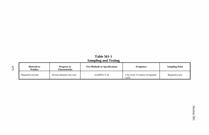
Section 561
475
Table 561-1Sampling and Testing
Material orProduct
Property orCharacteristic
Test Methods or Specifications Frequency Sampling Point
Repaired concrete 50-mm diameter test core AASHTO T 24 1 for every 15 meters of repairedcrack.
Repaired crack
476
Section 562.) FORMS AND FALSEWORK
Description
562.01 This work consists of designing, constructing, and removing forms andfalsework to temporarily support concrete, girders, and other structural ele-ments until the structure is completed to the point it can support itself.
Design and Construction Requirements
562.02 Drawings. When complete details for forms and falsework are notshown, prepare and submit drawings according to Subsection 104.03. Showthe following, as applicable:
(a) Design and show the details for constructing safe and adequate forms andfalsework that provide the necessary rigidity, support the loads imposed, andproduce in the finished structure the required lines and grades. See Subsec-tion 562.03 for design loads. See Subsection 562.04 for design stresses,loadings, and deflections. See Subsection 562.05 for manufactured assem-blies.
(b) Show the maximum applied structural load on the foundation material.Include a drainage plan or description of how foundations will be protectedfrom saturation, erosion, and/or scour. See Subsection 562.06.
(c) Precisely describe all proposed material. Describe the material that is notdescribable by standard nomenclature (such as AASHTO or ASTM specifi-cations) based on manufacturer's tests and recommended working loads.Evaluate falsework material and ascertain whether the physical propertiesand conditions of the material is such that it can support the loads assumedin the design.
(d) Furnish design calculations and material specifications showing that theproposed system will support the imposed concrete pressures and otherloads. Provide an outline of the proposed concrete placement operationlisting the equipment, labor, and procedures to be used for the duration ofeach operation. Include proposed placement rates and design pressures foreach pour. Include a superstructure placing diagram showing the concreteplacing sequence and construction joint locations.
Section 562
477
(e) Provide design calculations for proposed bridge falsework. A registeredprofessional engineer proficient in structural design shall design, sign, andseal the drawings. The falsework design calculations shall show the stressesand deflections in load supporting members.
(f) Show anticipated total settlements of falsework and forms. Include false-work footing settlement and joint take-up. Design for anticipated settlementsnot to exceed 25 millimeters. Design and detail falsework supporting deckslabs and overhangs on girder bridges so there is no differential settlementbetween the girders and the deck forms during placement of deck concrete.Design and construct the falsework to elevations that include anticipatedsettlement during concrete placement and required camber to compensate formember deflections during construction.
(g) Show the support systems for form panels supporting concrete deck slabsand overhangs on girder bridges.
(h) Show details for strengthening and protecting falsework over or adjacentto roadways and railroads during each phase of erection and removal. SeeSubsection 562.07.
(i) Include intended steel erection procedures with calculations in sufficientdetail to substantiate that the girder geometry will be correct. See Subsection562.08.
(j) Submit details of proposed anchorage and ties for void forms. See Sub-section 562.10 for void form requirements.
Submit separate falsework drawings for each structure, except for identicalstructures with identical falsework design and details. Do not start construc-tion of any unit of falsework until the drawings for that unit are reviewed andaccepted.
562.03 Design Loads.
(a) Vertical design loads. Dead loads include the mass of concrete, rein-forcing steel, forms, and falsework. Consider the entire superstructure, orany concrete mass being supported by falsework to be a fluid dead load withno ability to support itself. If the concrete is to be prestressed, design thefalsework to support any increased or readjusted loads caused by the pre-stressing forces.
Section 562
478
Assume the density of concrete, reinforcing steel, and forms to be not lessthan 2600 kilograms per cubic meter for normal concrete and not less than2100 kilograms per cubic meter for lightweight concrete.
Consider live loads to be the actual mass of equipment to be supported byfalsework applied as concentrated loads at the point of contact plus a uniformload of not less than 1000 pascals applied over the area supported, plus 1100newtons per meter applied at the outside edge of deck falsework overhangs.
The total vertical design load for falsework is the sum of vertical dead andlive loads. Use a total vertical design load of not less than 4800 pascals.
(b) Horizontal design loads. Use an assumed horizontal design load onfalsework towers, bents, frames, and other falsework structures to verifylateral stability. The assumed horizontal load is the sum of the actual hori-zontal loads due to equipment, construction sequence, or other causes and anallowance for wind. However, in no case is the assumed horizontal load tobe less than 2 percent of the total supported dead load at the location underconsideration.
The minimum wind allowance for each heavy-duty steel shoring having avertical load carrying capacity exceeding 130 kilonewtons per leg is the sumof the products of the wind impact area, shape factor, and the applicable windpressure value for each height zone. The wind impact area is the total pro-jected area of all the elements in the tower face normal to the applied wind.Assume the shape factor for heavy-duty shoring to be 2.2. Determine windpressure values from Table 562-1.
The minimum wind allowance on all other types of falsework, includingfalsework supported on heavy-duty shoring, is the sum of the products of thewind impact area and the applicable wind pressure value for each heightzone. The wind impact area is the gross projected area of the falsework andunrestrained portion of the permanent structure, excluding the areas betweenfalsework posts or towers where diagonal bracing is not used. Use designwind pressures from Table 562-2.
Design the falsework so it has sufficient rigidity to resist the assumed hori-zontal load without vertical dead load. Neglect the effects of frictional resis-tance.
Section 562
479
Table 562-1Design Wind Pressure - Heavy Duty Steel Shoring
Height ZoneAbove Ground
meter
Wind Pressure Value - Pa
Adjacent At OtherTo Traffic Locations
0 960 7209 -15 1200 960
15 - 30 1450 1200Over 30 1675 1450
Table 562-2Design Wind Pressure - Other Types of Falsework
Height Zone Above Ground
meter
Wind Pressure Value - Pa
For Members Overand Bents Adjacent At Other
To Traffic Locations Openings
0 320 Q 240 Q 9 - 15 400 Q 320 Q15 - 30 480 Q 400 QOver 30 560 Q 480 Q
Note: Q = 0.3 + 0.2W, but not more than 3. W is the width of the falseworksystem in meters measured in the direction of the wind force being considered.
(c) Lateral fluid pressure. For concrete with retarding admixture, fly ash,or other pozzolan replacement for cement, design forms, form ties, and brac-ing for a lateral fluid pressure based on concrete with a density of 2400 kilo-grams per cubic meter. For concrete containing no pozzolans or admixtures,which affect the time to initial set, determine the lateral fluid pressure basedon concrete temperature and rate of placement according to ACI standard347R, Guide for Formwork for Concrete.
3309(L/d)2
Section 562
480
562.04 Design Stresses, Loads, and Deflections. The allowable maximumdesign stresses and loads listed in this section are based on the use of undam-aged, high-quality material. If lesser quality material is used, reduce the allow-able stresses and loads. Do not exceed the following maximum stresses, loads,and deflections in the falsework design:
(a) Timber.
Compression perpendicular to the grain = 3100 kilopascals
Compression parallel to the grain = megapascals(1)
Note: (1) Not to exceed 11 megapascals.
Where:L = Unsupported lengthd = Least dimension of a square or rectangular column or the width
of a square of equivalent cross-sectional area for round columns
Flexural stress = 12.4 megapascals
Note: Reduced to 10 megapascals for members with a nominal depth of 200millimeters or less.
Horizontal shear = 1300 kilopascals
Axial tension = 8.3 megapascals
Deflection due to the mass of concrete may not exceed 1/500 of the spaneven if the deflection is compensated for by camber strips.
Modulus of elasticity (E) for timber = 11.7 gigapascals
Maximum axial loading on timber piles = 400 kilonewtons
Design timber connections according to the stresses and loads allowed in theNational Design Specification for Wood Construction, as published by theNational Forest Products Association except:
82 750Ld/bt
Section 562
481
(1) Reductions in allowable loads required therein for high moisture con-dition of the lumber and service conditions do not apply.
(2) Use 75 percent of the tabulated design value as the design value ofbolts in two member connections (single shear).
(b) Steel. For identified grades of steel, do not exceed the design stresses(other than stresses due to flexural compression) specified in the Manual ofSteel Construction as published by the AISC.
When the grade of steel cannot be positively identified, do not exceed thedesign stresses, other than stresses due to flexural compression, either speci-fied in the AISC Manual for ASTM A 36M steel or the following:
Tension, axial and flexural = 150 megapascals
Compression, axial = 110 000 - 2.6(L/r)² kilopascals
Note: L/r shall not exceed 120.
Shear on the web gross section of rolled shapes = 100 megapascals
Web crippling for rolled shapes = 185 megapascals
For all grades of steel, do not exceed the following design stresses and de-flection:
Compression, flexural = megapascals(1)
Note: (1) Not to exceed 150 megapascals for unidentified steel or steel con-forming to ASTM A 36. Not to exceed 0.6 F for other identified steel.y
Where:L = Unsupported length.d = Least dimension of a square or rectangular column or the width
of a square of equivalent cross-sectional area for round col-umns or the depth of beams.
b = Width of the compression flange.t = Thickness of the compression flange.r = Radius of gyration of the member.F = Specified minimum yield stress for the grade of steel used.y
Section 562
482
Deflection due to the mass of concrete may not exceed 1/500 of the spaneven if the deflection is compensated for by camber strips.
Modulus of elasticity (E) for steel = 210 gigapascals
(c) Other requirements. Limit falsework spans supporting T-beam girderbridges to 4.3 meters plus 8.5 times the overall depth of T-beam girder.
562.05 Manufactured Assemblies. For jacks, brackets, columns, joists andother manufactured devices, do not exceed the manufacturer's recommenda-tions or 40 percent of the ultimate load carrying capacity of the assembly basedon the manufacturer's tests or additional tests ordered. Limit maximum allow-able dead load deflection of joists to 1/500 of their spans.
Furnish catalog or equivalent data showing the manufacturer's recommenda-tions or perform tests, as necessary, to demonstrate the adequacy of any manu-factured device proposed for use. Do not substitute other manufacturer's com-ponents unless the manufacturer's data encompasses such substitutions or fieldtests reaffirm the integrity of the system.
If a component of the falsework system consists of a steel frame tower exceed-ing 2 or more tiers high, the differential leg loading within the steel tower unitshall not exceed 4 to 1. An exception may be approved if the manufacturer ofthe steel frame certifies, based on manufacturer's tests, that the proposed differ-ential loadings are not detrimental to the safe load carrying capacity of the steelframe.
562.06 Falsework Foundations. Field verify all ground elevations at pro-posed foundation locations before design.
Where spread footing type foundations are used, determine the bearing ca-pacity of the soil. The maximum allowable bearing capacity for foundationmaterial, other than rock, is 190 kilopascals.
Do not locate the edge of footings closer than 300 millimeters from the inter-section of the bench and the top of the slope. Unless the excavation for foot-ings is adequately supported by shoring, do not locate the edge of the footingscloser than 1.2 meters or the depth of excavation, whichever is greater, fromthe edge of the excavation.
Section 562
483
When a pile-type foundation is used, use according to Section 551. Whenfalsework is supported by footings placed on paved, well-compacted slopes ofberm fills, do not strut the falsework to columns unless the column is foundedon rock or supported by piling. Size spread footings to support the footing design load at the assumed bearingcapacity of the soil without exceeding anticipated settlements. Provide steelreinforcement in concrete footings.
When individual steel towers have maximum leg loads exceeding 130 kilo-newtons, provide for uniform settlement under all legs or each tower under allloading conditions.
Protect the foundation from adverse effects for the duration of its use. Advisethe CO of actions that will be taken to protect the foundation.
562.07 Falsework Over or Adjacent to Roadways and Railroads. Designand construct the falsework to be protected from vehicle impact. This includesfalsework posts that support members crossing over a roadway or railroad andother falsework posts if they are located in the row of falsework posts nearestto the roadway or railroad and if the horizontal distance from the traffic sideof the falsework to the edge of pavement or to a point 3 meters from the center-line of track is less than the total height of the falsework.
Provide additional features to ensure that this falsework will remain stable ifsubjected to impact by vehicles. Use vertical design loads for these falseworkposts, columns, and towers (but not footings) that are greater than or equal toeither of the following:
(a) 150 percent of the design load calculated according to Subsection 562.03,but not including any increased or readjusted loads caused by prestressingforces
(b) the increased or readjusted loads caused by prestressing forces
Install temporary traffic barriers before erecting falsework towers or columnsadjacent to an open public roadway. Locate barriers so that falsework footingsor pile caps are at least 75 millimeters clear of concrete traffic barriers and allother falsework members are at least 300 millimeters clear. Do not removebarriers until approved.
Section 562
484
Use falsework columns that are steel with a minimum section modulus abouteach axis of 156 000 cubic millimeters or sound timbers with a minimum sec-tion modulus about each axis of 4 100 000 cubic millimeters.
Mechanically connect the base of each column or tower frame supportingfalsework over or immediately adjacent to an open public road to its supportingfooting or provide other lateral restraint to withstand a force of not less than 9kilonewtons applied to the base of the column in any direction. Mechanicallyconnect such columns or frames to the falsework cap or stringer to resist ahorizontal force of not less than 4.5 kilonewtons in any direction. Neglect theeffects of frictional resistance.
Brace or tie exterior girders, upon which overhanging bridge deck falseworkbrackets are hung, to the adjacent interior girders as necessary to prevent rota-tion of exterior girders or overstressing the exterior girder web.
Mechanically connect all exterior falsework stringers and stringers adjacent tothe end of discontinuous caps, the stringer or stringers over points of minimumvertical clearance and every fifth remaining stringer, to the falsework cap orframing. Provide mechanical connections capable of resisting a load in anydirection, including uplift on the stringer, of not less than 2.2 kilonewtons.Install connections before traffic is allowed to pass beneath the span.
Use 16 millimeters diameter or larger bolts to connect timber members used tobrace falsework bents located adjacent to roadways or railroads.
Sheath falsework bents within 6 meters of the centerline of a railroad tracksolid in the area between 1 and 5 meters above the track on the side facing thetrack. Construct sheathing of plywood not less than 16 millimeters thick orlumber not less than 25 millimeters nominal thickness. Provide adequate brac-ing on such bents so that the bent resists the required assumed horizontalload or 22 kilonewtons, whichever is greater, without the aid of sheathing.
Provide at least the minimum required vertical and horizontal clearancesthrough falsework for roadways, railroads, pedestrians, and boats.
Section 562
485
562.08 Falsework for Steel Structures.
(a) Use falsework design loads consisting of the mass of structural steel, theload of supported erection equipment, and all other loads supported by thefalsework.
(b) Design falsework and forms for concrete supported on steel structures sothat loads are applied to girder webs within 150 millimeters of a flange orstiffener. Distribute the loads in a manner that does not produce local distor-tion of the web. Do not use deck overhang forms that require holes to bedrilled into the girder webs.
(c) Strut and tie exterior girders supporting overhanging deck falseworkbrackets to adjacent interior girders to prevent distortion and overstressingof the exterior girder web.
(d) Do not apply loads to existing, new, or partially completed structures thatexceed the load carrying capacity of any part of the structure according to theload factor design methods of the AASHTO Bridge Design Specificationsusing load group IB.
(e) Build supporting falsework that will accommodate the proposed methodof erection without overstressing the structural steel, as required, and willproduce the required final structural geometry, intended continuity, andstructural action.
562.09 Falsework Construction. Construct falsework to conform to theaccepted drawings.
When welding is required, submit a welder certification for each welder ac-cording to Subsection 555.18.
Build camber into the falsework to compensate for falsework deflection andanticipated structure deflection. Camber shown on the plans or specified by theCO is for anticipated structure deflection only.
Attach tell-tales to soffit of concrete forms in enough systematically placedlocations to be able to determine from the ground the total settlement of thestructure while concrete is placed.
Section 562
486
Do not apply dead loads, other than forms and reinforcing steel, to any false-work until authorized.
Discontinue concrete placement and take corrective action, if unanticipatedevents occur, including settlements that cause a deviation of more then 10millimeters from those shown on the falsework drawings. If satisfactory cor-rective action is not taken before initial set, remove all unacceptable concrete.
562.10 Forms. For exposed concrete surfaces, use U.S. Product Standard PS1 for exterior B-B (concrete form) class I plywood or other approved materialthat will produce a smooth and uniform concrete surface. Use only form panelsin good condition free of defects on exposed surfaces. If form panel materialother than plywood is used, it shall have flexural strength, modulus of elastic-ity, and other physical properties equal to or greater than the physical proper-ties for the type of plywood specified.
Furnish and place form panels for exposed surfaces in uniform widths of notless than 1 meter and in uniform lengths of not less than 2 meters, except wherethe width of the member formed is less than 1 meter.
Arrange panels in symmetrical patterns conforming to the general lines of thestructure. Place panels for vertical surfaces with the long dimension horizontaland with horizontal joints level and continuous. For walls with sloping foot-ings which do not abut other walls, panels may be placed with the long dimen-sion parallel to the footing.
Precisely align form panels on each side of the panel joint by means of sup-ports or fasteners common to both panels. Provide 19-millimeter triangularfillets at all sharp edges of the concrete.
Devices may be cast into the concrete for later use in supporting forms or forlifting precast members. Do not use driven devices for fastening forms or formsupports to concrete. Use form ties consisting of form bolts, clamps, or otherdevices necessary to prevent spreading of the forms during concrete placement.
Section 562
487
Do not use form ties consisting of twisted wire loops. Use form ties and an-chors that can be removed without damaging the concrete surface. Constructmetal ties or anchorages within the forms to permit their removal to a depth ofat least 25 millimeters from the face without damage to the concrete. Fillcavities with cement mortar and finish to a sound, smooth, uniform coloredsurface.
Construct all exposed concrete surfaces that will not be completely enclosedor hidden below the permanent ground surface so the formed surface of theconcrete does not undulate more than 2.5 millimeters or 1/360 of the center tocenter distance between studs, joists, form stiffeners, form fasteners, or wales.Interior surfaces of underground drainage structures are considered to be com-pletely enclosed surfaces. Form all exposed surfaces for each element of aconcrete structure with the same forming material or with materials that pro-duce similar surface textures, color, and appearance.
Support roadway slab forms of box girder type structures on wales or similarsupports fastened, as nearly as possible, to the top of the web walls.
Construct concrete forms mortar-tight, true to the dimensions, lines, and gradesof the structure, and of sufficient strength to prevent appreciable deflectionduring placement of concrete. Place all material required to be embedded inthe concrete before concrete placement. Clean inside surfaces of forms of alldirt, mortar and foreign material. Remove all loose material before the com-pletion of forming for the roadway deck slab of cast-in-place box girders orcells or voids of other members in which the forms are to either remain in placeor be removed.
Form exposed curved surfaces to follow the shape of the curve, except onretaining walls that follow a horizontal curve. The wall stems may be a seriesof short chords if all of the following apply:
Chords within the panel are the same length. Chords do not vary from a true curve by more than 15 millimeters at any
point. All panel points are on the true curve.
When architectural treatment is required, make the angle points for chords inwall stems fall at vertical rustication joints.
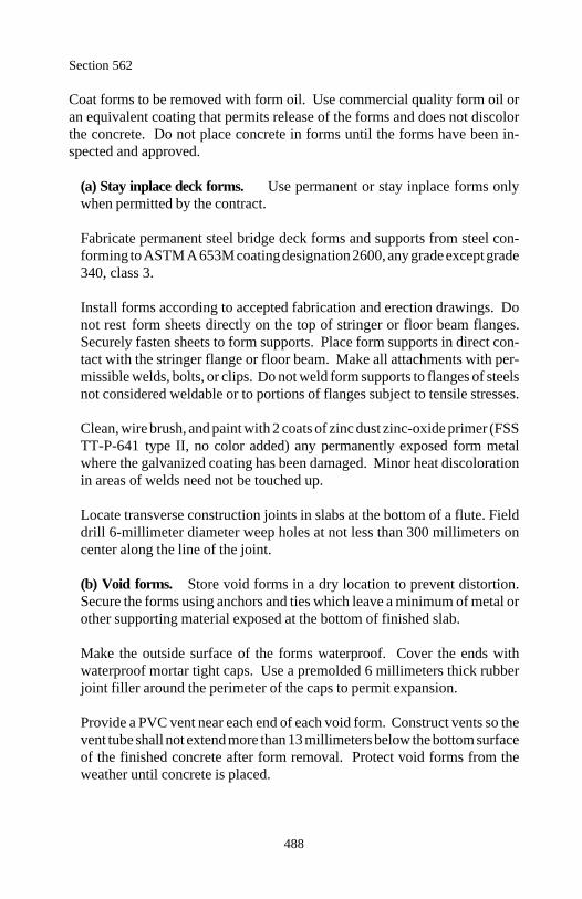
Section 562
488
Coat forms to be removed with form oil. Use commercial quality form oil oran equivalent coating that permits release of the forms and does not discolorthe concrete. Do not place concrete in forms until the forms have been in-spected and approved.
(a) Stay inplace deck forms. Use permanent or stay inplace forms onlywhen permitted by the contract.
Fabricate permanent steel bridge deck forms and supports from steel con-forming to ASTM A 653M coating designation 2600, any grade except grade340, class 3.
Install forms according to accepted fabrication and erection drawings. Donot rest form sheets directly on the top of stringer or floor beam flanges.Securely fasten sheets to form supports. Place form supports in direct con-tact with the stringer flange or floor beam. Make all attachments with per-missible welds, bolts, or clips. Do not weld form supports to flanges of steelsnot considered weldable or to portions of flanges subject to tensile stresses.
Clean, wire brush, and paint with 2 coats of zinc dust zinc-oxide primer (FSSTT-P-641 type II, no color added) any permanently exposed form metalwhere the galvanized coating has been damaged. Minor heat discolorationin areas of welds need not be touched up.
Locate transverse construction joints in slabs at the bottom of a flute. Fielddrill 6-millimeter diameter weep holes at not less than 300 millimeters oncenter along the line of the joint.
(b) Void forms. Store void forms in a dry location to prevent distortion.Secure the forms using anchors and ties which leave a minimum of metal orother supporting material exposed at the bottom of finished slab.
Make the outside surface of the forms waterproof. Cover the ends withwaterproof mortar tight caps. Use a premolded 6 millimeters thick rubberjoint filler around the perimeter of the caps to permit expansion.
Provide a PVC vent near each end of each void form. Construct vents so thevent tube shall not extend more than 13 millimeters below the bottom surfaceof the finished concrete after form removal. Protect void forms from theweather until concrete is placed.
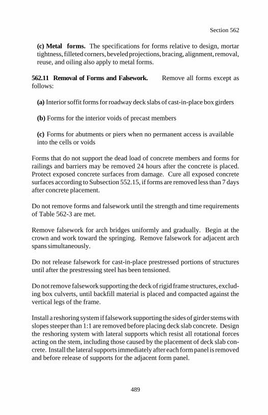
Section 562
489
(c) Metal forms. The specifications for forms relative to design, mortartightness, filleted corners, beveled projections, bracing, alignment, removal,reuse, and oiling also apply to metal forms.
562.11 Removal of Forms and Falsework. Remove all forms except asfollows:
(a) Interior soffit forms for roadway deck slabs of cast-in-place box girders
(b) Forms for the interior voids of precast members
(c) Forms for abutments or piers when no permanent access is availableinto the cells or voids
Forms that do not support the dead load of concrete members and forms forrailings and barriers may be removed 24 hours after the concrete is placed.Protect exposed concrete surfaces from damage. Cure all exposed concretesurfaces according to Subsection 552.15, if forms are removed less than 7 daysafter concrete placement.
Do not remove forms and falsework until the strength and time requirementsof Table 562-3 are met.
Remove falsework for arch bridges uniformly and gradually. Begin at thecrown and work toward the springing. Remove falsework for adjacent archspans simultaneously.
Do not release falsework for cast-in-place prestressed portions of structuresuntil after the prestressing steel has been tensioned.
Do not remove falsework supporting the deck of rigid frame structures, exclud-ing box culverts, until backfill material is placed and compacted against thevertical legs of the frame.
Install a reshoring system if falsework supporting the sides of girder stems withslopes steeper than 1:1 are removed before placing deck slab concrete. Designthe reshoring system with lateral supports which resist all rotational forcesacting on the stem, including those caused by the placement of deck slab con-crete. Install the lateral supports immediately after each form panel is removedand before release of supports for the adjacent form panel.
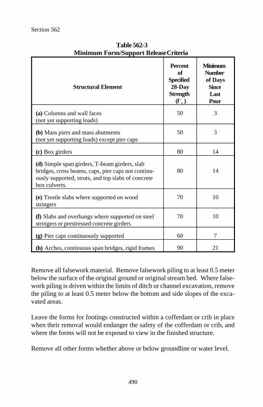
Section 562
490
Table 562-3Minimum Form/Support Release Criteria
Structural Element 28-Day
Percent Minimumof Number
Specified of Days
Strength (f )c
SinceLastPour
(a) Columns and wall faces(not yet supporting loads)
50 3
(b) Mass piers and mass abutments (not yet supporting loads) except pier caps
50 3
(c) Box girders 80 14
(d) Simple span girders, T-beam girders, slabbridges, cross beams, caps, pier caps not continu-ously supported, struts, and top slabs of concretebox culverts.
80 14
(e) Trestle slabs where supported on wood stringers
70 10
(f) Slabs and overhangs where supported on steelstringers or prestressed concrete girders
70 10
(g) Pier caps continuously supported 60 7
(h) Arches, continuous span bridges, rigid frames 90 21
Remove all falsework material. Remove falsework piling to at least 0.5 meterbelow the surface of the original ground or original stream bed. Where false-work piling is driven within the limits of ditch or channel excavation, removethe piling to at least 0.5 meter below the bottom and side slopes of the exca-vated areas.
Leave the forms for footings constructed within a cofferdam or crib in placewhen their removal would endanger the safety of the cofferdam or crib, andwhere the forms will not be exposed to view in the finished structure.
Remove all other forms whether above or below groundline or water level.

Section 562
491
562.12 Acceptance. Forms and falsework (including design, construction,and removal) will be evaluated under Subsections 106.02, 106.03, and 106.04.
When the falsework installation is complete and before concrete placement orremoval begins, have the falsework inspected by a licensed professional engi-neer proficient in structural design. Certify in writing that the installationconforms to the contract, the approved falsework drawings (including approvedchanges), and acceptable engineering practices. Provide a copy of thecertification before concrete placement.
Measurement and Payment
562.13 See Subsection 109.05.
Do not measure forms and falsework for payment.
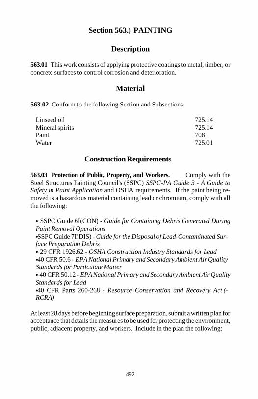
492
Section 563.) PAINTING
Description
563.01 This work consists of applying protective coatings to metal, timber, orconcrete surfaces to control corrosion and deterioration.
Material
563.02 Conform to the following Section and Subsections:
Linseed oil 725.14Mineral spirits 725.14Paint 708Water 725.01
Construction Requirements
563.03 Protection of Public, Property, and Workers. Comply with theSteel Structures Painting Council's (SSPC) SSPC-PA Guide 3 - A Guide toSafety in Paint Application and OSHA requirements. If the paint being re-moved is a hazardous material containing lead or chromium, comply with allthe following:
SSPC Guide 6I(CON) - Guide for Containing Debris Generated DuringPaint Removal Operations SSPC Guide 7I(DIS) - Guide for the Disposal of Lead-Contaminated Sur-
face Preparation Debris 29 CFR 1926.62 - OSHA Construction Industry Standards for Lead 40 CFR 50.6 - EPA National Primary and Secondary Ambient Air Quality
Standards for Particulate Matter 40 CFR 50.12 - EPA National Primary and Secondary Ambient Air Quality
Standards for Lead 40 CFR Parts 260-268 - Resource Conservation and Recovery Act (-
RCRA)
At least 28 days before beginning surface preparation, submit a written plan foracceptance that details the measures to be used for protecting the environment,public, adjacent property, and workers. Include in the plan the following:

Section 563
493
(a) Manufacturer's material safety data sheets and product data sheets for allcleaning and painting products.
(b) A detailed containment plan for removed material, cleaning products, andpaint debris. Include details of attachment to the structure.
(c) A detailed disposal plan for removed material, cleaning products, andpaint debris.
(d) Specific safety measures to protect workers from site hazards includingfalls, fumes, fires, or explosions.
(e) If paint being removed is a hazardous material include specific safetymeasures to comply with 29 CFR 1926.62, 40 CFR 50.6, 40 CFR 50.12, and40 CFR Parts 260-268. Document compliance upon request.
(f) Emergency spill procedures.
(g) A Competent person responsible for ensuring that all necessary health,safety, and containment measures are enacted and maintained.
After acceptance, perform work according to the plan. If the measures fail toperform as intended, immediately stop work and take corrective action. Collectand properly dispose of all material including waste water that is used in pre-paring, cleaning, or painting.
563.04 Protection of the Work. Protect adjacent surfaces that are not to bepainted by using tarps, screens, paper, cloth, or other suitable means. Preventcontamination of freshly painted surfaces by dust, oil, grease, or other harmfulor deleterious material.
563.05 Surface Preparation, General. Notify the CO in writing at least 7days before beginning operations. Immediately before painting, prepare thesurface according to the following:
(a) Clean the surface to the specified cleanliness level. (b) Remove dirt, dust, and other contaminants from the surface using meth-ods recommended by the paint manufacturer. (c) Thoroughly dry the surface.
Section 563
494
(d) Determine that the surface temperature is between 10 and 40 C.(e) Determine that the surface temperature is 3 C or more above the dewpoint according to ASTM E 337.(f) Determine that the humidity is 85 percent less, unless specified otherwiseon the manufacturer's product data sheet.
Suitable engineering controls such as enclosures and dehumidification may beused to provide the conditions required above.
563.06 Paint Application, General. Use safe handling practices that conformto the manufacturer's safety data sheet and instructions. Mix and apply paintaccording to the product instructions. Mix paint with mechanical mixers fora sufficient length of time to thoroughly blend the pigment and vehicle togeth-er. Continue the mixing during application. Do not thin paint that is formu-lated ready for application.
Paint in a neat and workmanlike manner that does not produce excessive paintbuild-up, runs, sags, skips, holidays, or thin areas in the paint film. Measurethe wet film thickness during application and adjust the application rate suchthat, after curing, the desired dry film thickness is obtained. Apply paint bybrush, spray, roller, or any combination thereof if permitted by the manufac-turer's product data sheet.
Use brushes that have sufficient bristle body and length to spread the paint ina uniform film. Use round, oval shaped brushes, or flat brushes no wider than120 millimeters. Evenly spread and thoroughly brush out the paint as it isapplied.
Use airless or conventional spray equipment with suitable traps, filters, orseparators to exclude oil and water from the compressed air. Use compressedair that does not show black or wet spots when tested according to ASTM D4285. Use the spray gun tip sizes and pressures recommended by the manu-facturer.
Use rollers only on flat, even surfaces. Do not use rollers that leave a stippledtexture in the paint film.
Use sheepskin daubers, bottle brushes, or other acceptable methods to paintsurfaces that are inaccessible for painting by regular means.
Section 563
495
Cure each coat of paint according to the manufacturer's recommendations.Correct all thin areas, skips, holidays, and other deficiencies before the nextapplication of paint. Tint succeeding applications of paint to contrast with thepaint being covered. The CO will approve the color for the finish coat beforeapplication.
Coat surfaces that will be inaccessible after erection with the full number ofundercoats required before erection. After erection thoroughly clean all areaswhere the undercoating is damaged or deteriorated and spot coat these with thespecified undercoats to the required thickness before applying the final coat.
563.07 Structural Iron and Steel.
(a) Paint systems.
(1) New surfaces or surfaces with all existing paint removed. Furnisha paint system shown in Table 563-1.
(2) Surfaces with existing sound paint. Furnish a paint system com-patible with the existing paint. Furnish a system shown in Table 563-2 ora system approved for use on steel structures by the state highway agencyin the state in which the structure is located.
At least 14 days before ordering paint, verify compatibility of the pro-posed system with the existing system as follows:
(a) Select a test area of at least 3 square meters in a condition repre-sentative of the condition of the structure. Perform the specified levelof surface preparation and apply the proposed system to the existingtopcoat and to the existing primer. Observe for lifting, bleeding, blis-tering, wrinkling, cracking, flaking, or other evidence of incompatibil-ity.
(b) Verify that no indication of incompatibility exists at least 14 daysafter the application of each product. Perform adhesion tests accord-ing to ASTM D 3359 method A. Notify the CO immediately if adhe-sion testing fails at the interface of the existing system and substrateor between the existing finish coat and primer. An adhesion failureindicates incompatibility. Choose a more compatible paint system.
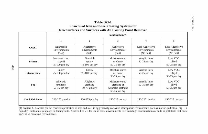
Section 563
496
Table 563-1Structural Iron and Steel Coating Systems for
New Surfaces and Surfaces with All Existing Paint Removed
COAT
Paint System (1)
1 2 3 4 5
AggressiveEnvironments
(Salt)
AggressiveEnvironments
(Salt)
AggressiveEnvironments
(Salt)
Less AggressiveEnvironments
(No Salt)
Less AggressiveEnvironments
(No Salt)
PrimerInorganic zinc
type II75-100 µm dry
Zinc-richepoxy
75-100 µm dry
Moisture-curedurethane
50-75 µm dry
Acrylic latex50-75 µm dry
Low VOCalkyd
50-75 µm dry
IntermediateEpoxy
75-100 µm dryEpoxy
75-100 µm dryMoisture-cured
urethane50-75 µm dry
Acrylic latex50-75 µm dry
Low VOCalkyd
50-75 µm dry
TopAliphaticurethane
50-75 µm dry
Aliphaticurethane
50-75 µm dry
Moisture-curedurethane or
Aliphatic urethane50-75 µm dry
Acrylic latex50-75 µm dry
Low VOCalkyd
50-75 µm dry
Total Thickness 200-275 µm dry 200-275 µm dry 150-225 µm dry 150-225 µm dry 150-225 µm dry
(1) System 1, 2, or 3 is for the corrosion protection of iron and steel in aggressively corrosive atmospheric environments such as marine, industrial, hig hhumidity, or structures exposed to deicing salts. System 4 or 5 is for use in those environments free from high concentrations of salts or pollutants that causeaggressive corrosion environments.
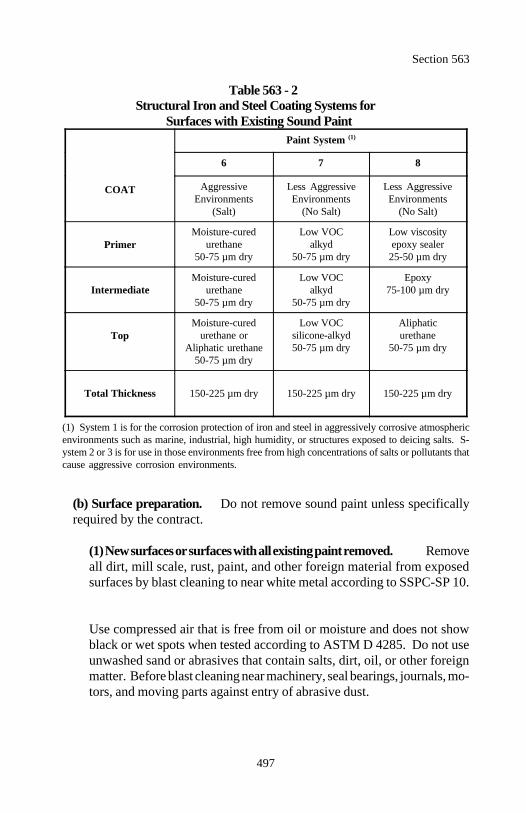
Section 563
497
Table 563 - 2Structural Iron and Steel Coating Systems for
Surfaces with Existing Sound Paint
COAT
Paint System (1)
6 7 8
Aggressive Less Aggressive Less AggressiveEnvironments Environments Environments
(Salt) (No Salt) (No Salt)
PrimerMoisture-cured Low VOC Low viscosity
urethane alkyd epoxy sealer50-75 µm dry 50-75 µm dry 25-50 µm dry
Intermediate urethane alkyd 75-100 µm dryMoisture-cured Low VOC Epoxy
50-75 µm dry 50-75 µm dry
TopMoisture-cured Low VOC Aliphatic
urethane or silicone-alkyd urethaneAliphatic urethane 50-75 µm dry 50-75 µm dry
50-75 µm dry
Total Thickness 150-225 µm dry 150-225 µm dry 150-225 µm dry
(1) System 1 is for the corrosion protection of iron and steel in aggressively corrosive atmosphericenvironments such as marine, industrial, high humidity, or structures exposed to deicing salts. S-ystem 2 or 3 is for use in those environments free from high concentrations of salts or pollutants thatcause aggressive corrosion environments.
(b) Surface preparation. Do not remove sound paint unless specificallyrequired by the contract.
(1) New surfaces or surfaces with all existing paint removed. Removeall dirt, mill scale, rust, paint, and other foreign material from exposedsurfaces by blast cleaning to near white metal according to SSPC-SP 10.
Use compressed air that is free from oil or moisture and does not showblack or wet spots when tested according to ASTM D 4285. Do not useunwashed sand or abrasives that contain salts, dirt, oil, or other foreignmatter. Before blast cleaning near machinery, seal bearings, journals, mo-tors, and moving parts against entry of abrasive dust.
Section 563
498
Blast clean with clean dry slag, mineral grit, steel shot, or steel grit. Usea suitable gradation to produce a dense, uniform anchor pattern. Producean anchor profile height of 25 to 50 micrometers, but not less than thatrecommended by the paint system manufacturer's product data sheet.Measure anchor profile height using the tape method according to ASTMD 4417.
The same day cleaning is performed, remove dirt, dust, and other debrisfrom the surface by brushing, blowing with clean dry air, or vacuumingand apply the first coat of paint to the blast cleaned surfaces. If thecleaned surfaces rust or become contaminated before painting, repeat theblast cleaning.
(2) Surfaces with existing sound paint. Wash all areas to be paintedwith pressurized water to remove dirt, surface chalking, loose rust, andcontaminants such as chlorides. Maintain a wash water pressure of atleast 3.5 megapascals. Capture all wash water and removed waste accord-ing to appropriate regulations.
Clean according to SSPC-SP 2 - Hand Tool Cleaning, SSPC-SP 3 - PowerTool Cleaning, or SSPC-SP 6 - Commercial Blast Cleaning to removedirt, loose mill scale, loose rust, or paint that is not firmly bonded to theunderlying surface. Clean small areas that show pinhole corrosion, stonedamage from traffic, or minor scratches. Clean at least 50 millimetersbeyond the damaged areas. Feather edges of remaining old paint toachieve a reasonably smooth surface.
The same day hand- or power-tool cleaning is performed, remove dirt,dust, and other contaminants from the surface with solvent cleaning meth-ods according to SSPC-SP 1 and spot paint all bare steel areas with thefirst coat of paint. If the cleaned surfaces rust or become contaminatedbefore painting, repeat solvent cleaning. Repair all damage to sound paintby applying the entire system.
(c) Application of paints. Apply each coat to the wet film thickness asrecommended by the paint manufacturer to obtain the specified dry filmthickness. Verify the application rate of each coat with a wet film paintthickness gauge immediately after applying paint to the surface. Confirm theapplication rate by measuring the dry film thickness after the solvent hasevaporated from the surface.
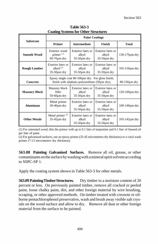
Section 563
499
Table 563-3Coating Systems for Other Structures
SubstratePaint Coatings
Primer Intermediate Finish Total
Smooth Wood primer alkyd alkyd 130-170µm dryExterior wood Exterior latex or Exterior latex or
(1)
60-70µm dry 35-50µm dry 35-50µm dry
Rough LumberExterior latex or Exterior latex or Exterior latex or
alkyd alkyd alkyd 105-150µm dry(1)
35-50µm dry 35-50µm dry 35-50µm dry
Concrete finish with aliphatic-polyurethane (50µm dry). 80-150µm dryEpoxy single coat 80-100µm dry. For gloss finish,
Masonry BlockMasonry block Exterior latex or Exterior latex or
filler alkyd alkyd 120-160µm dry50-60µm dry 35-50µm dry 35-50µm dry
AluminumMetal primer Exterior latex or Exterior latex or30-40µm dry alkyd alkyd 100-140µm dry
35-50µm dry 35-50µm dry
Other MetalsMetal primer Exterior latex or Exterior latex or(2)
35-45µm dry alkyd alkyd 105-145µm dry35-50µm dry 35-50µm dry
(1) For untreated wood, thin the primer with up to 0.1 liter of turpentine and 0.1 liter of linseed oilper liter of paint.(2) For galvanized surfaces, use an epoxy primer (35-45 micrometers dry thickness) or a vinyl washprimer (7-13 micrometers dry thickness).
563.08 Painting Galvanized Surfaces. Remove all oil, grease, or othercontaminants on the surface by washing with a mineral spirit solvent accordingto SSPC-SP 1.
Apply the coating system shown in Table 563-3 for other metals.
563.09 Painting Timber Structures. Dry timber to a moisture content of 20percent or less. On previously painted timber, remove all cracked or peeledpaint, loose chalky paint, dirt, and other foreign material by wire brushing,scraping, or other approved methods. On timber treated with creosote or oil-borne pentachlorophenol preservative, wash and brush away visible salt crys-tals on the wood surface and allow to dry. Remove all dust or other foreignmaterial from the surface to be painted.
Section 563
500
Apply the coating system shown in Table 563-3. The primer may be appliedbefore erection. After the primer dries and the timber is in place, fill all cracks,checks, nail holes, or other depressions flush with the surface using approvedputty. Evenly spread and thoroughly work the paint into all corners and re-cesses. Allow the full thickness of the applied coat of paint to dry before ap-plying the next coat.
563.10 Painting Concrete Structures. Remove all laitance, dust, foreignmaterial, curing compound, form oil, grease or other deleterious material fromthe concrete surface. Remove form oil, grease, or curing compound by wash-ing with a 5 percent solution of trisodium phosphate and rinsing with cleanwater. Allow the surface to dry completely.
Give the cleaned surface a light abrasive sweep to remove mortar wash or othercontaminants. Remove all residue and dust by hand, broom, compressed airor other approved methods.
Apply the coating system coatings shown in Table 563-3. Evenly spread andthoroughly work the paint into all corners and recesses. Allow the full thick-ness of the applied coat of paint to dry before applying the next coat.
563.12 Acceptance. Paint material will be evaluated under Subsections106.02 and 106.03. If sampling and testing of paint components is required,sampling will be according to FSS 141 method 1021 and the testing of thepaint properties will be according to the procedures and methods listed in FSS141.
Painting application will be evaluated under Subsection 106.02 and 106.04.The dry paint thickness on steel structures will be determined using a type Imagnetic film thickness gauge according to SSPC-PA 2 or by using destructivemethods according to ASTM D 4138. If destructive methods are used, repairtest locations in an approved manner.
Measurement
563.12 Measure painting by the square meter or by the lump sum. Whenmeasurement is by the square meter, measure the visible surface areapainted.

Section 563
501
Payment
563.13 The accepted quantities, measured as provided above, will be paid atthe contract price per unit of measurement for the pay items listed below thatare shown in the bid schedule. Payment will be full compensation for the workprescribed in this Section. See Subsection 109.05.
Payment will be made under:
Pay Item Pay Unit
56301 Painting, description structure Lump sum56302 Painting, description structure Square meter
502
Section 564.) BEARING DEVICES
Description
564.01 This work consists of furnishing and installing bridge bearings. Bear-ing devices are designated as elastomeric, rocker, roller, and sliding plate.
Material
564.02 Conform to the following Subsections:
Elastomeric bearing pads 717.10Tetrafluoroethylene (TFE) surfaces for bearings 717.11
Construction Requirements
564.03 General.
(a) Drawings. Prepare and submit drawings for the bearings according toSubsection 104.03 and Section 18 of the AASHTO Standard Specificationsfor Highway Bridges Division II, Volume II. Show all details of the bearingsincluding the material proposed for use. Obtain approval before beginningfabrication.
(b) Fabrication. Fabricate bearings according to Section 18 of theAASHTO Standard Specifications for Highway Bridges Division II, VolumeII. The surface finish of bearing components in contact with each other orwith concrete, but not embedded in concrete, shall conform to Subsection555.08(e).
Preassemble bearing assemblies in the shop and check for proper complete-ness and geometry. Galvanize steel bearing components and anchor boltsaccording to Subsection 717.07. Do not galvanize stainless steel bearingcomponents or anchor bolts.
(c) Packaging, handling, and storage. Before shipping from the manufac-turer, clearly identify each bearing component and mark on its top the loca-tion and orientation in the structure. Securely bolt, strap, or otherwise fastenthe bearings to prevent any relative movement.
Section 564
503
Package bearings so they are protected from damage due to shipping, han-dling, weather, or other hazards. Do not dismantle bearing assemblies at thesite except for inspection or installation.
Store all bearing devices and components at the work site in a location thatprovides protection from environmental and physical damage.
(d) Construction and installation. Clean the bearings of all deleterioussubstances. Install the bearings to the positions shown on the drawings. Setbearings and bearing components to the dimensions shown on the drawingsor as prescribed by the manufacturer. Adjust according to the manufacturer'sinstructions to compensate for installation temperature and future movementsof the bridge.
Set bridge bearings level at the exact elevation and position. Provide full andeven bearing on all external bearing contact surfaces. If bearing surfaces areat improper elevations, not level, or if bearings cannot otherwise be set prop-erly, notify the CO and submit a written proposal to modify the installationfor approval.
Bed metallic bearing assemblies, not embedded in concrete, on concrete withan approved filler or fabric material.
Set elastomeric bearing pads directly on properly prepared concrete surfaceswithout bedding material.
Machine bearing surfaces seated directly on steel to provide a level andplanar surface upon which to place the bearing.
564.04 Elastomeric Bearings. The bearings include nonreinforced pads(consisting of elastomer only) and reinforced bearings with steel or fabric lami-nates.
Reinforce elastomeric bearings more than 15 millimeters thick with laminatesevery 15 millimeters through the entire thickness.
If not specified, use 50-durometer elastomer, capable of sustaining an averagecompressive stress of 7 megapascals.
Section 564
504
Fabricate elastomeric bearings according to AASHTO M 251. Use materialthat meets the flash tolerance, finish, and appearance requirements of the Rub-ber Handbook as published by the Rubber Manufacturer's Association Incorpo-rated, RMA F3 and T.063 for molded bearings and RMA F2 for extrudedbearings. Determine compliance with AASHTO M 251, level I acceptance cri-teria.
Mark each reinforced bearing with indelible ink or flexible paint. The markinginformation shall include the order number, lot number, bearing identificationnumber, and elastomer type and grade number. Unless otherwise specified,mark on a face that is visible after erection of the bridge. Furnish a list of allindividual bearing numbers.
Place bearings on a level surface. Correct any misalignment in the support toform a level surface. Do not weld steel girders or base plates to the exteriorplates of the bearing unless there is more than 40 millimeters of steel betweenthe weld and elastomer. Do not expose the elastomer or elastomer bond toinstantaneous temperatures greater than 200 C.
564.05 Rocker, Roller, and Sliding Bearings. When TFE coatings are re-quired, use coatings conforming to Subsection 564.07.
Fabricate rocker, roller, and sliding bearings according to the details shown onthe plans and to Section 555. Perform fabrication according to the standardpractice in modern commercial shops. Remove burrs, rough and sharp edges,and other flaws. Stress relieve rocker, roller, and other bearings that are builtup by welding sections of plate together before boring, straightening, or fin-ished machining.
Thoroughly coat all contact surfaces with oil and graphite just before placingroller bearings. Install rocker, roller, and sliding bearings so they are verticalat the specified mean temperature after release of falsework and after anyshortening due to prestressing forces. Take into account any variation frommean temperature of the supported span at time of installation and any otheranticipated changes in length of the supported span.
Make sure the superstructure has full and free movement at movable bearings.Carefully position cylindrical bearings so that their axes of rotation align andcoincide with the axis of rotation of the superstructure.
Section 564
505
564.06 Masonry, Sole, and Shim Plates for Bearings. Provide metal platesused in masonry, sole, and shim plates, conforming to AASHTO M 270Mgrade 250.
Fabricate and finish steel according to Section 555. Form holes in bearingplates by drilling, punching, or accurately controlled oxygen cutting. Removeall burrs by grinding.
Accurately set bearing plates in level position as shown on the drawings andprovide a uniform bearing over the bearing contact area. When plates areembedded in concrete, make provision to keep them in correct position as theconcrete is placed.
564.07 Tetrafluoroethylene (TFE) Surfaces for Bearings. Furnish TFEmaterial that is factory-bonded, mechanically connected, or recessed into thebackup material as shown on the plans.
Bond or mechanically attach the fabric containing TFE fibers to a rigid sub-strate. Use a fabric capable of carrying unit loads of 70 megapascals withoutcold flow. Use a fabric-substrate bond capable of withstanding, without de-lamination, a shear force equal to 10 percent of the perpendicular or normalapplication loading plus any other bearing shear forces. Determine compliance using approved test methods and procedures accordingto Section 18, Subsection 18.8.3, AASHTO Standard Specifications for High-way Bridges Division II, Volume II. If the test facility does not permit testingcompleted bearings, manufacture extra bearings and prepare samples of at least450-kilonewton capacity at normal working stresses.
Determine static and dynamic coefficient of friction at first movement of thetest bearing at a sliding speed of less than 25 millimeters per minute. Thecoefficient of friction shall not exceed the coefficient of friction as specified inTable 564-1 or by the manufacturer.
Furnish a listing of all individual bearing numbers.
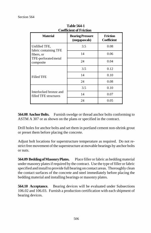
Section 564
506
Table 564-1Coefficient of Friction
Material Bearing Pressure Friction(megapascals) Coefficient
Unfilled TFE, 3.5 0.08fabric containing TFEfibers, orTFE-perforated metalcomposite
14 0.06
24 0.04
Filled TFE
3.5 0.12
14 0.10
24 0.08
Interlocked bronze andfilled TFE structures
3.5 0.10
14 0.07
24 0.05
564.08 Anchor Bolts. Furnish swedge or thread anchor bolts conforming toASTM A 307 or as shown on the plans or specified in the contract.
Drill holes for anchor bolts and set them in portland cement non-shrink groutor preset them before placing the concrete.
Adjust bolt locations for superstructure temperature as required. Do not re-strict free movement of the superstructure at movable bearings by anchor boltsor nuts.
564.09 Bedding of Masonry Plates. Place filler or fabric as bedding materialunder masonry plates if required by the contract. Use the type of filler or fabricspecified and install to provide full bearing on contact areas. Thoroughly cleanthe contact surfaces of the concrete and steel immediately before placing thebedding material and installing bearings or masonry plates.
564.10 Acceptance. Bearing devices will be evaluated under Subsections106.02 and 106.03. Furnish a production certification with each shipment ofbearing devices.
Section 564
507
Bearing device installation will be evaluated under Subsections 106.02 and106.04.
Measurement
564.11 Measure bearing devices by the each.
Payment
564.12 The accepted quantities, measured as provided above, will be paid atthe contract price per unit of measurement, for the pay item listed below thatis shown in the bid schedule. Payment will be full compensation for the workprescribed in this Section. See Subsection 109.05.
Payment will be made under:
Pay Item Pay Unit
56401 _________ bearing device Each
508
Section 565.) DRILLED SHAFTS
Description
565.01 This work consists of constructing drilled shafts.
Material
565.02 Conform to the following Section and Subsections:
Mineral slurry 725.26Reinforcing steel 709.01Structural concrete 552
Construction Requirements
565.03 Contractor Qualifications and Equipment Adequacy. Use person-nel with at least 3 or more years experience in the construction of drilled shafts.Provide personnel resumes of job experiences and appropriate documentationincluding names, addresses, and telephone numbers of organizations or associ-ations that verify the information. Acceptance of the proposed personnel re-sponsible for the construction of the drilled shafts is required before workbegins.
Submit an installation plan for acceptance at least 30 days before constructingdrilled shafts. Include the following information in the plan.
(a) List of proposed equipment to be used including cranes, drills, augers,bailing buckets, final cleaning equipment, desanding equipment, slurrypumps, core sampling equipment, tremies, concrete pumps, casings, etc.
(b) Details of overall construction operation sequence and the sequence ofshaft construction in bents or groups.
(c) Details of shaft excavation methods and procedures for maintaining cor-rect horizontal and vertical alignment of the excavation.
(d) When a mineral slurry is required, details of the methods to mix, circu-late, and de-sand the slurry.
(e) Details of methods to clean the shaft excavation.
Section 565
509
(f) Details of reinforcement placement including support and centralizationmethods.
(g) Details of concrete placement including proposed operational proceduresfor free fall, tremie, or pumping methods.
Acceptance of the Contractor's plan, personnel, and trial shafts does not relievethe Contractor of the responsibility for obtaining the required results.
565.04 Trial Drilled Shafts. When trial drilled shafts are required by thecontract, perform the work according to the applicable requirements of Subsec-tion 565.05 and the following.
Before drilling holes for production shafts, demonstrate that the proposedmethods and equipment are adequate by drilling a trial drilled shaft adjacentto the production shafts at an approved location. Make the center-to-centerspacing between the trial shaft and production shafts at least 3 shaft diametersor 2 bell diameters whichever is larger. Construct the trial drilled shaft to the same size and to the tip elevation of thedeepest production shaft shown on the plans. When bells are specified forproduction shafts, include a bell in the final shaft to verify the feasibility ofbelling in the specified bearing stratum.
If material caves into the drilled hole or the hole deforms excessively, case thehole. When casings are used, seat the casing as necessary to prevent cavingand to allow dewatering of the hole. Remove all material inside the hole.Keep the casing in place a minimum of 4 hours while attempting to remove allwater in the hole. Record the rate of groundwater seepage into the hole. Afterthis 4 hour period, fill the hole with saturated sand while the casing is removedto simulate the concreting operation and casing removal for the productiondrilled shafts. Concrete or reinforcing steel is not required in the trial drilledshaft.
If the trial drilled shaft is determined to be unsatisfactory, modify the methodsand equipment. Submit a new installation plan and drill a new trial drilledshaft at the Contractors' expense.
Once approval is given to construct the production drilled shafts, no changesare permitted in the installation plan without prior approval.
Section 565
510
565.05 Drilled Shafts.
(a) Excavation. Do not excavate additional shafts, allow excessive wheelloads, or allow excessive vibrations within 5 meters or 3 shaft diameters,whichever is greater, of a newly constructed shaft for at least 20 hours.Excavate for structure footings supported on drilled shafts and construct fillsbefore drilling. Position the drilled shaft within 75 millimeters of the re-quired position in a horizontal plane at the top of shaft elevation.
Excavate holes according to the accepted installation plan. Do not allow thealignment of a vertical shaft to vary from the required alignment by morethan 20 millimeters per meter of depth. Do not allow the alignment of abattered shaft to vary by more than 40 millimeters per meter of depth fromthe required batter alignment.
Provide equipment with the capability to excavate shafts 20 percent longerthan and the same diameter as those shown on the plans.
Maintain a log of material excavated from the drilled shaft that includes thefollowing information:
• Description and approximate top and bottom elevation of each type of soil or rock material encountered• Elevation and approximate rate of any seepage or groundwater en countered• Equipment used, time required to drill shaft, and all difficulties en countered• Remarks
(1) Dry method. Use the dry construction method at sites where thegroundwater level and soil conditions are suitable to permit constructionof the shaft in a relatively dry excavation and where the sides and bottomof the shaft may be visually inspected before placing concrete. The drymethod consists of drilling the shaft, removing accumulated water, remov-ing loose material from the excavation, placing the reinforcing cage, andconcreting the shaft in a relatively dry excavation.
The dry construction method can only be used when the trial shaft exca-vation demonstrates all the following:
Section 565
511
(a) Less than 300 millimeters of water accumulates above the base ofthe hole during a 1-hour period when no pumping is permitted.(b) The sides and bottom of the hole remain stable without detrimentalcaving, sloughing, or swelling over a 4-hour period immediately fol-lowing completion of excavation.(c) Loose material and water can be satisfactorily removed beforeinspection and before concrete placement.
(2) Wet method. Use the wet construction method or the casing con-struction method for shafts that do not meet the above requirements forthe dry construction method. This method consists of using water ormineral slurry to maintain stability of the hole perimeter while advancingthe excavation to final depth, placing the reinforcing cage, and concretingthe shaft.
The wet method involves the following work:
(a) Desanding and cleaning the slurry.(b) Final cleaning of the excavation using a bailing bucket, air lift,submersible pump, or other approved devices.(c) Placing the shaft concrete with a tremie or concrete pump begin-ning at the shaft bottom.(d) Providing, as needed, temporary surface casings to aid shaft align-ment and positioning.(e) Providing temporary surface casings to prevent sloughing of thetop of the shaft excavation unless it can be satisfactorily demonstratedthat the surface casing is not required.
Where drilled shafts are located in open water areas, extend exterior cas-ings from above the water elevation into the ground to protect the shaftconcrete from water action during placement and curing of the concrete.Install the exterior casing in a manner that will produce a positive seal atthe bottom of the casing to prevent piping of water or entry of other mate-rial from the shaft excavation.
When it is determined that the hole sidewall has softened due to excavationmethods, swelled due to delays in concreting, or degraded because of slurrycake buildup, overream sidewall a minimum of 15 millimeters or a maximumof 75 millimeters to sound material.
Section 565
512
At the time of concrete placement, clean the hole so no more than 50 percentof the bottom of each hole has more than 10 millimeters of sediment and themaximum depth of sediment at any place on the bottom of the hole does notexceed 40 millimeters. For dry holes, reduce the depth of water to 75 milli-meters or less before placing concrete.
(b) Mineral slurry . Premix the mineral slurry with clean fresh water ac-cording to the mineral manufacturer to allow for hydration before introduc-tion into the shaft excavation. Use slurry tanks of adequate capacity forslurry circulation, storage, and treatment. Do not use excavated slurry pitsor the shaft excavation to mix the slurry. Do not add mineral componentdirectly into the shaft excavation.
Provide desanding equipment to limit slurry sand content to less than 4 per-cent by volume at any point in bore hole. Desanding is not required forsetting temporary casings, sign posts, or lighting mast foundations.
During drilling, maintain slurry surface in the shaft at least 1 meter above thehighest expected adjacent piezometric water pressure head and at a levelsufficient to prevent caving of the hole.
When there is a sudden significant loss of slurry from the hole, stop drillingand take corrective measures to prevent slurry loss. Prevent the slurry fromsetting up in the shaft. If at any time the slurry construction method fails toproduce the desired final results, discontinue and use an approved alternativemethod.
Maintain density, viscosity, and pH of the mineral slurry during shaft excava-tion and until concrete placement within the acceptable ranges shown inTable 565-1. Take slurry samples using an approved sampling tool. Extractslurry samples from the base of the shaft and 3 meters up from the base of theshaft. Perform 4 sets of tests during first 8 hours of slurry use. When resultsare acceptable and consistent, the testing frequency may be decreased to onetest set for every 4 hours of slurry use.
When a slurry sample is unacceptable, make necessary corrections to bringthe slurry within specifications. Do not place concrete until the results of theresampling and retesting indicate acceptable values.
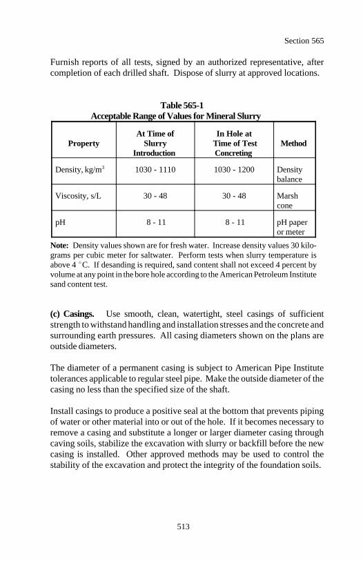
Section 565
513
Furnish reports of all tests, signed by an authorized representative, aftercompletion of each drilled shaft. Dispose of slurry at approved locations.
Table 565-1Acceptable Range of Values for Mineral Slurry
Property Slurry Time of Test MethodAt Time of In Hole at
Introduction Concreting
Density, kg/m 1030 - 1110 1030 - 1200 Density3
balance
Viscosity, s/L 30 - 48 30 - 48 Marshcone
pH 8 - 11 8 - 11 pH paperor meter
Note: Density values shown are for fresh water. Increase density values 30 kilo-grams per cubic meter for saltwater. Perform tests when slurry temperature isabove 4 C. If desanding is required, sand content shall not exceed 4 percent byvolume at any point in the bore hole according to the American Petroleum Institutesand content test.
(c) Casings. Use smooth, clean, watertight, steel casings of sufficientstrength to withstand handling and installation stresses and the concrete andsurrounding earth pressures. All casing diameters shown on the plans areoutside diameters.
The diameter of a permanent casing is subject to American Pipe Institutetolerances applicable to regular steel pipe. Make the outside diameter of thecasing no less than the specified size of the shaft.
Install casings to produce a positive seal at the bottom that prevents pipingof water or other material into or out of the hole. If it becomes necessary toremove a casing and substitute a longer or larger diameter casing throughcaving soils, stabilize the excavation with slurry or backfill before the newcasing is installed. Other approved methods may be used to control thestability of the excavation and protect the integrity of the foundation soils.
Section 565
514
All subsurface casings are to be considered temporary unless designated inthe contract as permanent casing. Remove temporary casing before com-pleting placement of concrete in any shaft excavation requiring casing. Dur-ing casing extraction, maintain a level of fresh concrete in the casing that isa minimum of 1.5 meters above the surrounding level of water or drillingfluid. Exercise care during casing removal to maintain an adequate level ofconcrete within the casing so fluid trapped behind the casing is displacedupward and discharged at the ground surface without contaminating or dis-placing the shaft concrete.
Temporary casings that have become bound or fouled during shaft construc-tion and cannot be practically removed are considered to be a defect in thedrilled shaft. Correct defective shafts using approved methods. Correctiveaction may consist of, but is not limited to, the following:
(1) Removing the shaft concrete and extending the shaft deeper to com-pensate for loss of frictional capacity in the cased zone(2) Providing straddle shafts to compensate for capacity loss(3) Providing a replacement shaft
When a casing is designated as permanent, cut the casing off at the requiredelevation and leave in place.
565.06 Reinforcing Steel for Drilled Shafts. Perform the work according toSection 554. Place the reinforcing steel cage as a unit immediately after theshaft excavation is inspected and accepted and before concrete placement.Securely wire together contact reinforcing steel lap splices. If the concrete isnot placed immediately after the cage is installed, the cage may have to beremoved before placing the concrete to verify the integrity of the excavatedarea and to ensure loose material is removed from the bottom of the hole.
Tie and support the reinforcing steel so it remains within the required toler-ances. Securely tie concrete spacers or other approved spacing devices at fifthpoints around the cage perimeter and space at intervals not to exceed 3 metersalong the length of the cage. Use spacers of approved material at least equalin quality and durability to the shaft concrete.
Handle reinforcing cages to avoid distortion or racking of the steel.
Section 565
515
During concrete placement, provide positive support from the top for thereinforcing steel cage. Maintain the top of the reinforcing steel cage no morethan 150 millimeters above and no more than 75 millimeters below the requiredposition. If the reinforcing steel cage is not maintained within tolerances, makeacceptable corrections and do not construct additional shafts until the methodof reinforcing steel cage support has been approved.
565.07 Concrete for Drilled Shafts. Place concrete immediately after allexcavation is complete and the reinforcing steel cage is in place. Furnishconcrete conforming to Section 552 except as otherwise indicated herein. Forshafts constructed without drilling fluid, use class A structural concrete havinga slump of 175±25 millimeters. For shafts constructed with drilling fluid, useclass A structural concrete having a slump of 200±25 millimeters. Use sealconcrete for under water placement. Do not use seal concrete above thefreeze/thaw or wet/dry zone of the hole. Place underwater concrete accordingto Subsection 552.11(e) except as modified herein. The method of underwaterplacement is subject to approval.
Adjust approved admixtures for project conditions to ensure that the concretehas the minimum required slump for at least 2 hours. Submit trial mix andslump loss test results for concrete at ambient temperatures appropriate for siteconditions.
Place each load of concrete within 2 hours of batching. Longer placement timemay be permitted if the concrete mix maintains the minimum required slumpfor longer than 2 hours. Do not retemper concrete that has developed its initialset.
Place concrete in one continuous operation from bottom to top of the shaft.Continue placing concrete after the shaft excavation is full and until acceptablequality concrete is evident at the top of shaft. Before initial concrete set, con-solidate the top 3 meters of the shaft concrete using acceptable vibratory equip-ment. Finish the top of the shaft to +25 millimeters or -75 millimeters from therequired elevation. For wet holes, do not consolidate until all water or slurryabove the concrete surface has been removed. Place concrete either by freefall, tremie, or concrete pump.
(a) Free-fall concrete placement . Use free-fall placement only in dry holeswith an 8-meter maximum height of free-fall. The concrete shall fall directlyto the shaft base without contacting either the rebar cage or hole sidewall.
Section 565
516
Drop chutes may be used to direct placement of free-fall concrete. Dropchutes consist of a smooth tube of either one-piece construction or sectionsthat can be added and removed. Place concrete through a hopper at the topof the tube or through side openings as the drop chute is removed from theshaft during concrete placement. Support the drop chute so that the maxi-mum height of free-fall of the concrete measured from the bottom of thechute is 8 meters. If concrete placement causes the shaft excavation to caveor slough or if the concrete strikes the rebar cage or sidewall, reduce theheight of free-fall and/or reduce the rate of concrete flow into the excavation.If placement cannot be satisfactorily accomplished by free-fall, use tremie orpumping to place the concrete.
(b) Tremies. Use tremies for concrete placement in either wet or dry holes.A tremie consists of a tube of sufficient length, mass, and diameter to dis-charge concrete at the shaft base. Do not use tremies that contain aluminumparts that will come in contact with the concrete. Make the tremie insidediameter at least 6 times the maximum size of aggregate used in the concretemix and not less than 250 millimeters. Make the inside and outside surfacesof the tremie clean and smooth. Make the wall thick enough to preventcrimping or sharp bends.
Use a watertight tremie in accordance with Subsection 552.11(e) for wetholes. Construct the discharge end of the tremie to permit free radial flow ofconcrete during placement. Place the tremie discharge at the shaft baseelevation. Place the concrete in a continuous flow. Keep the tremie dis-charge immersed at least 1.5 meters below the surface of the fluid concrete.Maintain a positive head of concrete in the tremie at all times. If at any timeduring the concrete placement, the tremie discharge is removed from thefluid concrete column and discharges concrete above the rising concretesurface into displaced water, remove the reinforcing cage and concrete,complete any necessary sidewall removal as directed, and reconstruct theshaft.
(c) Pumped concrete. Use pumped concrete placement in either wet or dryholes. Use 100-millimeter minimum diameter discharge tubes with water-tight joints. Place the discharge tube at the shaft base elevation.
Use a sealed discharge tube according to Subsection 552.11(e) for wet holes.If a plug is used, remove it from the hole or use a plug made from approvedmaterial that will prevent a defect in the shaft if not removed.
Section 565
517
Place the concrete in a continuous flow. Keep pump discharge tube im-mersed at least 1.5 meters below the surface of the fluid concrete. If at anytime during the concrete placement, the discharge tube is removed from thefluid concrete column and discharges concrete above the rising concretesurface into displaced water, remove the reinforcing cage and concrete,complete any necessary sidewall removal as directed by the CO, and recon-struct the shaft.
When the top of shaft is above ground, use a removable form or other approvedmeans to form the shaft to at least 0.5 meter below finished ground. Formsmay be removed provided the requirements in Subsection 562.11 and Table562-3(a) are complied with and the shaft concrete has not been exposed tosaltwater or moving water for 7 days. Strip the forms without damaging theconcrete.
Remove the top portion of the drilled shaft concrete before continuing withcolumn construction when it is determined the concrete has been effected byunderwater placement.
565.08 Acceptance. Material for mineral slurry will be evaluated under Sub-sections 106.02 and 106.03.
Construction of drilled shafts will be evaluated under Subsections 106.02 and106.04.
Concrete will be evaluated under Section 552. Concrete, tremie placed orpumped, will be sampled at point of discharge into the tremie or concrete pumphopper.
Reinforcing steel will be evaluated under Section 554.
Measurement
565.09 Measure drilled shafts by the meter from the plan top elevation to theapproved tip. Do not measure portions of shafts extending deeper than ap-proved.
Do not measure concrete or reinforcing steel for payment.
Section 565
518
Measure trial drilled shafts, determined to be satisfactory, by the meter fromthe approved tip elevation to the ground surface at the center of the shaft.
Measure drilled shaft bells by the each.
Payment
565.10 The accepted quantities, measured as provided above, will be paid atthe contract price per unit of measurement for the pay items listed below thatare shown in the bid schedule. Payment will be full compensation for the workprescribed in this Section. See Subsection 109.05.
Payment will be made under:
Pay Item Pay Unit
56501 Drilled shafts Meter56502 Trial drilled shaft Each56503 Bell Each
519
DIVISION 600Incidental Construction
520
Section 601.) MINOR CONCRETE STRUCTURES
Description
601.01 This work consists of constructing minor concrete structures.
Material
601.02 Conform to the following Subsections:
Air-entraining admixtures 711.02Chemical admixtures 711.03Coarse aggregate 703.02Curing material 711.01Fine aggregate 703.01Fly ash 725.04Joint fillers 712.01Portland cement 701.01Precast concrete curbing 725.06Precast concrete units 725.11Reinforcing steel 709.01Structural steel 717.01Water 725.01
601.03 Concrete Composition. Conform to Table 601-1. Before batchingconcrete, submit the proposed concrete proportions for approval on FormFHWA 1606 Minor Portland Cement Concrete Mix Design Trial BatchSummary or other approved form. As a minimum, submit the following:
(a) Type and source(s) of all material proposed for use.(b) Material certification for all material proposed for use.(c) Saturated surface dry mass of the fine and coarse aggregate per cubicmeter of concrete.(d) Gradation of fine and coarse aggregate.(e) Mass of mixing water per cubic meter of concrete.(f) Mass of cement per cubic meter of concrete. Fly ash, ground iron blast-furnace slag, or silica fume may be substituted for cement according toSubsection 552.03(g).(g) Entrained air content of plastic concrete in percent by volume.(h) Maximum slump of plastic concrete in millimeters.
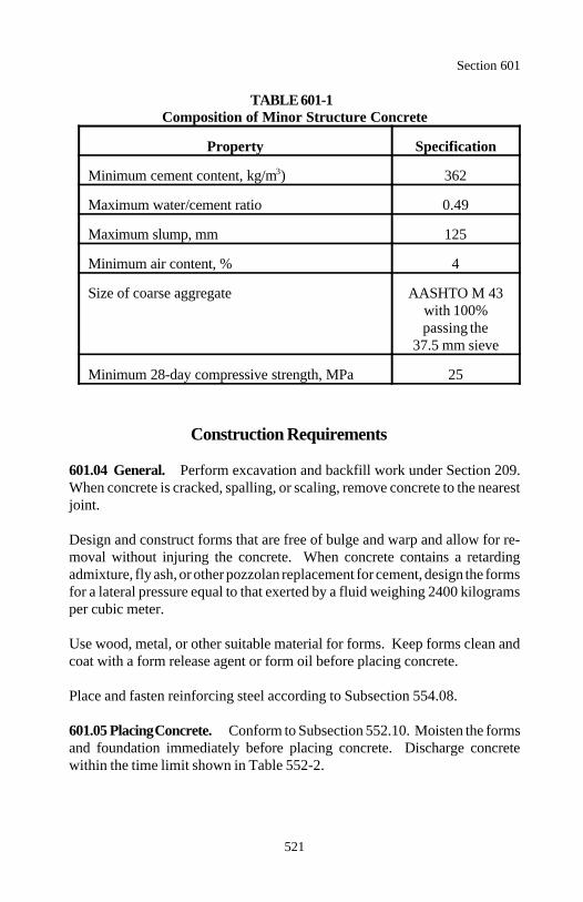
Section 601
521
TABLE 601-1Composition of Minor Structure Concrete
Property Specification
Minimum cement content, kg/m ) 3623
Maximum water/cement ratio 0.49
Maximum slump, mm 125
Minimum air content, % 4
Size of coarse aggregate AASHTO M 43with 100%passing the
37.5 mm sieve
Minimum 28-day compressive strength, MPa 25
Construction Requirements
601.04 General. Perform excavation and backfill work under Section 209.When concrete is cracked, spalling, or scaling, remove concrete to the nearestjoint.
Design and construct forms that are free of bulge and warp and allow for re-moval without injuring the concrete. When concrete contains a retardingadmixture, fly ash, or other pozzolan replacement for cement, design the formsfor a lateral pressure equal to that exerted by a fluid weighing 2400 kilogramsper cubic meter.
Use wood, metal, or other suitable material for forms. Keep forms clean andcoat with a form release agent or form oil before placing concrete.
Place and fasten reinforcing steel according to Subsection 554.08.
601.05 Placing Concrete. Conform to Subsection 552.10. Moisten the formsand foundation immediately before placing concrete. Discharge concretewithin the time limit shown in Table 552-2.
Section 601
522
Place concrete to avoid segregation of material. Consolidate with vibratorsaccording to Subsection 552.11(d). Do not use aluminum pipe for transportingor placing concrete. The intervals between delivery of batches for a singlepour on a structure shall not exceed 30 minutes.
Do not apply water to plastic concrete surfaces during finishing operations.
601.06 Curing Concrete. Cure concrete a minimum of 7 days. If high earlystrength cement is used, cure concrete a minimum of 3 days. Cure accordingto Subsection 552.15. Finish exposed concrete surfaces according to Subsec-tion 552.16(a) or (b), as applicable.
601.07 Acceptance. Material for minor concrete structures includingconcrete, reinforcing steel, and structural steel for minor structures will beevaluated under Subsections 106.02 and 106.03. For confirming commercialcertifications of compressive strength, AASHTO T 23 is modified to allow the28-day cure in a waterproof mold.
Excavation and backfill will be evaluated under Section 209.
Construction or minor concrete structures will be evaluated under Subsections106.02 and 106.04.
Measurement
601.08 Measure concrete by the cubic meter in the structure, by the squaremeter, by the lump sum, or by the each.
Payment
601.09 The accepted quantities, measured as provided above, will be paid atthe contract price per unit of measurement for the pay items listed below thatare shown in the bid schedule. Payment will be full compensation for the workprescribed in this Section. See Subsection 109.05.
The concrete lump sum item will be paid based on the progress of the workunder this Section.

Section 601
523
Payment will be made under:
Pay Item Pay Unit
60101 Concrete Cubic meter60102 Concrete Square meter60103 Concrete Lump sum60104 Concrete Each
524
Section 602.) CULVERTS AND DRAINS
Description
602.01 This work consists of constructing culverts, drains, and precastconcrete box culverts.
Material
602.02 Conform to the following Subsections:
Aluminum-alloy corrugated pipe 707.03Aluminum-alloy spiral rib pipe 707.12Asphalt-coated pipe 707.04Asphalt mastic 702.07Concrete-lined corrugated steel pipe 707.13Fiber-bonded asphalt coated steel pipe 707.09Invert-paved corrugated steel pipe 707.14Joint fillers, sealants, and preformed joint seals 712.01Joint mortar 712.02Metallic-coated corrugated steel pipe 707.02Metallic-coated spiral rib pipe 707.11Non-reinforced concrete pipe 706.01Plastic pipe 706.08Polymer-coated steel pipe 707.08Precast reinforced concrete box sections 706.07Reinforced arch-shaped concrete pipe 706.04Reinforced concrete pipe 706.02Reinforced D-load concrete pipe 706.06Reinforced elliptically-shaped concrete pipe 706.05Slotted drain pipe 707.10Special grout backfill 704.11Watertight gaskets 712.03
Section 602
525
Construction Requirements
602.03 General. Use the same material and coating on all contiguous pipesections, extensions, and special sections, such as elbows and branch connec-tions. Culvert material, sizes, and approximate locations are shown on theplans. Determine the final location, length, and special sections in the field.Perform excavation and backfill work under Section 209.
602.04 Laying Concrete Pipe and Precast Concrete Box Culverts. Startat the lower end and lay the bell or groove end upgrade. Fully join all sections.Place circular pipe with elliptical reinforcement with the minor axis of thereinforcement in a vertical position. Construct the joints by one of thefollowing methods:
(a) Mortared joints. Clean the lower portion of the receiving end of thepipe. Plaster the inside with sufficient joint mortar to bring the inner surfacesof the abutting pipe sections flush and even. Fit the sections as close as theconstruction of the culvert permits. Fill and seal joints with mortar insideand out. Clean excess mortar from the inside of the joint.
Cure mortar outside of joints by covering with polyethylene sheeting orspraying with a curing compound. Backfill while mortar is plastic or, ifmortar sets before backfilling, wait at least 24 hours before backfilling.
(b) Gasket joints. Protect the joint ends from mud, silt, gravel, or otherunwanted material. Lay the pipe sections with gaskets attached. Remove,clean, relubricate, and reseat gaskets disturbed or contaminated.
Align the pipe sections. Force the joints home using the pipe manufacturers'recommended procedure. Do not drive or ram by hand or machinery. Blockthe last section of each day's run to prevent creep.
Section 602
526
602.05 Laying Metal Pipe. Lay pipe with outside laps of circumferentialjoints upgrade and longitudinal laps positioned other than in the invert. Placeelongated pipes with major axis within 5 degrees of vertical.
Join the sections together with coupling bands. Do not use flat bands orsmooth sleeve type couplers. Limit the use of coupling bands with projections(dimples) to attaching prefabricated flared end sections.
When aluminum alloys come in contact with other metals, coat the contactingsurfaces with asphalt mastic or a preapproved impregnated caulking compound.
602.06 Laying Plastic Pipe. Lay plastic pipe according to the pipe manu-facturer's recommendation.
602.07 Laying Slotted Drain Pipe. Join the sections together with couplingbands. Cover the slots with roofing paper or other approved covering duringbackfilling and paving to keep material out of the pipe. Backfill with a specialgrout backfill.
602.08 Acceptance. Material for culverts, drains, and precast concrete boxculverts furnished will be evaluated under Subsections 106.02 and 106.03.
Installation of culverts, drains and precast concrete box culverts will be evalua-ted under Subsections 106.02 and 106.04.
Excavation and backfill will be evaluated under Section 209.
Measurement
602.09 Measure pipe and box culverts by the meter along the invert.
Measure end sections, elbows, and branch connections by the each. If there isno pay item for elbows or branch connections, measure them as additional pipelength along the invert.
Section 602
527
Payment
602.10 The accepted quantities, measured as provided above, will be paid atthe contract price per unit of measurement for the pay items listed below thatare shown in the bid schedule. Payment will be full compensation for the workprescribed in this Section. See Subsection 109.05.
Payment will be made under:
Pay Item Pay Unit
60201 __ millimeter pipe culvert Meter60202 __ millimeter span, __ millimeter rise Meter
pipe arch culvert60203 __ millimeter equivalent diameter arch or Meter
elliptical culvert pipe60204 __ millimeter slotted drain pipe Meter60205 __ span, __ rise precast reinforced Meter
concrete box culvert60206 End section for __ millimeter pipe culvert Each60207 End section for __ millimeter span, Each
__ millimeter rise pipe arch culvert60208 End section for __ millimeter equivalent diameter Each
arch or elliptical culvert60209 Elbow (description) Each60210 Branch connection (description) Each
528
Section 603.) STRUCTURAL PLATE STRUCTURES
Description
603.01 This work consists of constructing structural plate pipes, arches, pipearches, boxes, and underpasses.
Material
603.02 Conform to the following Subsections:
Aluminum-alloy structural plate structures 707.06Asphalt-coated structural plate structures 707.07Steel structural plate structures 707.05
Construction Requirements
603.03 General. Perform excavation and backfill work under Section 209.
603.04 Erecting. Furnish steel, aluminum alloy, asphalt coated steel, orasphalt coated aluminum alloy structural plate structures.
Provide a copy of manufacturer's assembly instructions before assembly. Theinstructions shall show the position of each plate and assembly order. Assemble the structural plates according to the manufacturer's instructions.Exercise care in the use of drift pins and pry bars to prevent damage to thestructural plate and its coating. The plates shall have a proper fit-up.
Where aluminum alloys come in contact with other types of metal, coat thecontacting surfaces according to Subsection 602.05.
Torque steel bolts on steel plates to a minimum of 135 newton meters and amaximum of 400 newton meters.
Torque steel bolts and aluminum bolts on 2.5-millimeter thick aluminum platesto a minimum of 120 newton meters and a maximum of 155 newton meters.
Section 603
529
Torque steel bolts and aluminum bolts on 3-millimeter thick and heavieraluminum plates to a minimum of 155 newton meters and a maximum of 180newton meters.
For long-span structures:
(a) Tighten the longitudinal seams when the plates are assembled unless theplates are held in shape by cables, struts, or backfill. Properly align platescircumferentially to avoid permanent distortion from the design shape.Before backfilling, do not exceed 2 percent variation from the design shape.
(b) Do not distort the shape of the structure by operating equipment over ornear it.
(c) Provide suitable survey control on the structure to check structuremovement.
(d) Check and control the deflection movements of the structure during theentire backfilling operation. Do not exceed the manufacturer's recommendedlimits.
(e) Provide a manufacturer's representative to monitor the erecting andbackfilling of the structure.
603.05 Acceptance. Material for structural plate structures will be evaluatedunder Subsections 106.02 and 106.03.
Installation of structural plate structures will be evaluated under Subsections106.02 and 106.04.
Excavation and backfill will be evaluated under Section 209.
Measurement
603.06 Measure structural plate pipes, pipe arches, boxes, and underpasses bythe meter along the invert.
Measure structural plate arches by the meter along the average of thespringline lengths.
Payment
Section 603
530
603.07 The accepted quantities, measured as provided above, will be paid atthe contract price per unit of measurement for the pay items listed below thatare shown in the bid schedule. Payment will be full compensation for the workprescribed in this Section. See Subsection 109.05.
Payment will be made under:
Pay Item Pay Unit
60301 (diameter) millimeter structural plate pipe, Meter (metal thickness) millimeter
60302 ___ span, ___ rise, structural plate Meterpipe-arch, (metal thickness) millimeter
60303 ___ span, ___ rise, structural plate Meterunderpass, (metal thickness) millimeter
60304 ___ span, ___ rise, structural plate Meterarch, (metal thickness) millimeter
60305 ___ span, ___ rise, structural plate Meterbox, (metal thickness) millimeter
531
Section 604.) MANHOLES, INLETS,AND CATCH BASINS
Description
604.01 This work consists of constructing or adjusting manholes, inlets, catchbasins, junction boxes, and spring boxes.
Material
604.02 Conform to the following Section and Subsections:
Concrete 601Concrete brick 725.08Concrete masonry blocks 725.09Corrugated metal units 725.13Frames, grates, covers, and ladder rungs 725.12Grout 725.22Joint fillers, sealants, and preformed joint seals 712.01Joint mortar 712.02Precast concrete units 725.11Reinforcing steel 709.01Watertight gaskets 712.03
Construction Requirements
604.03 General. Perform excavation and backfill work under Section 209.
604.04 Concrete Construction. Construct concrete manholes, inlets, andcatch basins according to Section 601. Concrete units may be cast-in-place orprecast. Finish the surface according to Subsection 552.16(a) or (b) asapplicable.
Where a pipe enters through an existing concrete wall, cut the concrete andsteel reinforcement in a manner that will not loosen the reinforcement in thewall. Cut the steel reinforcement flush with the opening wall face. Grout alljoints and openings cut in the wall.
Finish the channel flow line in manholes, inlets, and catch basins accurately tomatch the pipe flow line.
Section 604
532
Assemble precast concrete manhole sections with flexible watertight gasketsor mastic joint fillers in the tongue and groove joints. If gaskets are used,handle the precast units carefully after the gasket has been attached to avoiddamaging the gasket or contaminating the joint. Attain the proper alignmentbefore the joints are forced home. Maintain partial support during the insertionof the tongue or spigot to minimize the unequal lateral pressure on the gasketand to maintain concentricity until the gasket is properly positioned. If masticis used, apply mastic joint filler according to the manufacturer's recommenda-tions.
Set metal frames in a full joint mortar bed.
Grout or use a preformed joint seal to make all joints and openings watertight.Finish mortar joints with a bead on the outside and a smooth finish on theinside.
Space ladder rungs uniformly on 300-millimeter centers and align vertically.Grout ladder rungs into precast concrete walls.
604.05 Masonry Block Construction. Construct concrete footings accordingto Section 601. Construct block masonry plumb. Stagger vertical joints andset block with the cells vertical. Dampen block to reduce the rate ofabsorption. Butter bearing members and vertical joints full of mortar. Bondblock with mortar on all sides. Construct joints straight, level, plumb, flush,and 6 to 13 millimeters thick. Backfill the structure after the masonry blockhas cured according to Subsection 552.15 for 7 days. 604.06 Metal Construction. Fabricate metal drop inlets from the samematerial as adjoining metal pipes.
604.07 Grade Adjustment of Existing Structures. Adjust metal frames andgrates to grade before placing the surface course.
Remove and clean the frames, covers, and grates. Trim the walls down to solidmaterial. Reconstruct the walls with the same material as existing and reset thecleaned frames at the required elevation.
When the existing casting and supporting walls are in good condition, anapproved device may be used to adjust the manhole casting cover to the correctgrade without reconstructing the walls or resetting the frame.
Section 604
533
When catch basins and inlets are adjusted to grade and abut existing concreteconstruction, separate the castings from the adjacent concrete with a preformedexpansion joint no less than 12 millimeters thick.
Clean each structure of all accumulated silt, debris, or foreign matter.
When an existing structure is abandoned, seal all pipes entering the structurewith a tight fitting plug of concrete not less than 150 millimeters thick or watertight masonry not less than 200 millimeters thick. Fracture the base of concretestructure to prevent entrapment of water. Obliterate the top of the structure toan elevation at least 1 meter below finished grade and backfill according toSection 209.
604.08 Acceptance. Precast concrete units (including manholes, inlets, catchbasins, junction boxes, and spring boxes) furnished will be evaluated underSubsections 106.02 and 106.03.
Material (except concrete) for cast-in-place concrete units (including manholes,inlets, catch basins, junction boxes, and spring boxes) will be evaluated underSubsections 106.02 and 106.03. Construction of cast-in-place concrete unitswill be evaluated under Subsections 106.02 and 106.04.
Concrete for cast-in-place units will be evaluated under Section 601.
Excavation and backfill will be evaluated under Section 209.
Installation and adjustment of concrete units (including manholes, inlets, catchbasins, junction boxes, and spring boxes) will be evaluated under Subsections106.02 and 106.04.
Measurement
604.09 Measure manholes by the meter from finished grade to the flow linesurface of the manhole or by the each.
Measure inlets, catch basins, manhole and inlet adjustments, capping inlets andmanholes, junction boxes, and spring boxes by the each.

Section 604
534
Measure metal frames and grates and removing and resetting metal frames andgrates by the each unless included as part of the original inlet, manhole, orcatch basin construction. The frame and the grate or cover used with itconstitute one unit.
Payment
604.10 The accepted quantities, measured as provided above, will be paid atthe contract price per unit of measurement for the pay items listed below thatare shown in the bid schedule. Payment will be full compensation for the workprescribed in this Section. See Subsection 109.05.
Payment will be made under:
Pay Item Pay Unit
60401 Manhole (description) Each60402 Manhole (description) Meter60403 Inlet (description) Each60404 Catch basin (description) Each60405 Manhole adjustment Each60406 Inlet adjustment Each60407 Capping inlets and manholes Each 60408 Junction box Each60409 Metal frame and grate (description) Each60410 Spring box Each60411 Removing and resetting metal frame and grate Each
535
Section 605.) UNDERDRAINS, SHEET DRAINS, ANDPAVEMENT EDGE DRAINS
Description
605.01 This work consists of furnishing and installing underdrains, sheetdrains, and pavement edge drains.
Material
605.02 Conform to the following Subsections:
Aluminum-alloy corrugated pipe 707.03Asphalt-coated pipe 707.04Geocomposite drains 714.02Geotextile type I 714.01Granular backfill 703.03Metallic coated corrugated steel pipe 707.02Perforated concrete pipe 706.03Plastic pipe 706.08Sand 703.15Structural backfill 704.04
Construction Requirements
605.03 General. Use the same material and coating on all contiguous drainsections, extensions, elbows, branch connections, and other special sections.
Drain material, size, and approximate location are shown on the plans. Deter-mine the final location and length in the field.
Perform excavation and backfill work under Section 209.
If geotextile or geocomposite is used, smooth the trench surfaces by removingall projections that may damage the geotextile or geocomposite. Replacegeotextile or geocomposite damaged during installation. Make repairs togeocomposites according to the manufacturer's recommendations.
Section 605
536
Do not permit soil or other foreign material to enter the drain systems. Plug theupgrade end of installations.
Furnish nonperforated pipe for outlet pipe. Install outlet pipe according toSection 602. Immediately place and secure a screen made of 1.4-millimeterdiameter galvanized wire having approximately 13 by 13-millimeter meshopenings over the outlet ends of all exposed pipes and weep holes.
605.04 Placing Underdrain. Place a layer of granular backfill at least 50millimeters thick in the bottom of the trench.
Furnish a collector pipe at least 125 millimeters in size with all underdrains.
Join pipe sections securely with coupling fittings or bands. Join polyvinylchloride (PVC) and acrylonitrile-butadiene-styrene (ABS) pipe using either aflexible elastomeric seal or solvent cement. Join polyethylene pipe with snap-on, screw-on, or wrap around coupling bands as recommended by themanufacturer.
Backfill and compact all trenches within the limits of the roadbed according toSection 209, except use granular backfill material. Trenches for geocompositeunderdrains within the limits of the roadbed may also be backfilled with cleansand and compacted.
When underdrain is placed in ditchlines, prevent infiltration of surface waterby placing material conforming to AASHTO M 145 classification group A-4,A-5, A-6, or A-7 in the top 300 millimeters of the trench.
(a) Standard underdrain. When geotextile is required, place the longdimension of the geotextile parallel to the centerline of the trench. Positionthe geotextile, without stretching in contact with the trench surface. Overlapthe joints a minimum of 600 millimeters with the upstream geotextile placedover the downstream geotextile.
Place collector pipe with the perforations down.
Place granular backfill to a height of 300 millimeters above the top of thecollector pipe and compact. Do not displace the collector pipe. Place andcompact the remainder of the granular backfill material according to Section209.
Section 605
537
Fold the geotextile over the top of the granular backfill with a minimumoverlap of 300 millimeters.
(b) Geocomposite underdrain. Extend the geotextile from the bottom ofthe drainage core around the collector pipe.
Construct splices and install outlet fittings according to the manufacturer'srecommendations. Prevent infiltration of soil into the geocomposite core.Construct the geocomposite underdrain so not to impede flow through thegeocomposite core.
Place the assembled geocomposite in the trench with the face of the geo-composite against the inflow side of the trench. If the trench wall isirregular, smooth the trench wall or place a layer of granular backfill betweenthe geocomposite and the trench wall. Temporarily support the drain againstthe trench wall while backfilling.
When the trench is less than 0.5 meter wide, backfill the trench using cleansand. Backfilling and compacting in layers is not required. Compact thesand by wheel rolling, vibrating, tamping with a mechanical tamper, orflooding with water.
When the trench is 0.5 meter wide or more, place granular backfill or cleansand to a height of 300 millimeters above the top of the collector pipe andcompact. Place and compact the remainder of the granular backfill materialor clean sand according to Section 209.
605.05 Placing Geocomposite Sheet Drain. Do not place sheet drain againsta mortar course less than 4 days old.
When a geocomposite is used in conjunction with a waterproof membrane,install drainage panels compatible with the membrane using methods recom-mended by the membrane manufacturer. Assemble and place the geocompositedrain against the surface to be backfilled according to the manufacturer'srecommendations.
Splice geocomposite drains so the flow across the edges is continuous.Overlap the geotextile a minimum of 75 millimeters in the direction of waterflow. For vertical splices, overlap the geotextile in the direction backfillproceeds.
Section 605
538
Connect the drainage core to the collector pipe or weep holes so the flow iscontinuous through the system. Extend the geotextile from the bottom of thedrainage core around the collector pipe.
Backfill with structural backfill and compact according to Subsections208.10 and 208.11.
605.06 Placing Geocomposite Pavement Edge Drain. Assemble the geo-composite pavement edge drain and outlet material according to themanufacturer's recommendations and place it in the trench. If the trench wallis irregular, smooth the trench wall or place a layer of clean sand between thegeocomposite and the trench wall. Temporarily support the drain against thetrench wall while backfilling.
When the trench is less than 0.5 meter wide, backfill the trench using cleansand. Backfilling and compacting in layers is not required. Compact the sandby wheel rolling, vibrating, tamping with a mechanical tamper, or flooding withwater.
When the trench is 0.5 meter wide or more, place and compact granularbackfill or clean sand according to Section 209.
605.07 Acceptance. Material (except granular backfill) for underdrains, sheetdrains, and edge drains will be evaluated under Subsections 106.02 and 106.03.
Granular backfill will be evaluated under Subsections 106.02 and 106.04.See Table 605-1 for sampling and testing requirements.
Excavation and backfill will be evaluated under Section 209.
Geotextile will be evaluated under Section 207.
Outlet pipes will be evaluated under Section 602.
Installation of underdrains, sheet drains, and edge drains will be evaluatedunder Subsections 106.02 and 106.04.
Section 605
539
Measurement
605.08 Measure underdrain systems, standard underdrain systems, geo-composite underdrain systems, and pavement edge drain systems by the meter.When measurement is for a system, do not measure geotextiles, collector pipes,backfill, and outlet pipes that are part of the system unless a pay item is shownin the contract.
Measure sheet drain systems by the square meter of front face in final positionexcluding overlaps.
Measure collector pipe and outlet pipe by the meter.
Measure granular backfill and sand by the cubic meter in place.
Payment
605.09 The accepted quantities, measured as provided above, will be paid atthe contract price per unit of measurement for the pay items listed below thatare shown in the bid schedule. Payment will be full compensation for the workprescribed in this Section. See Subsection 109.05.
Payment will be made under:
Pay Item Pay Unit
60501 Underdrain system Meter60502 Standard underdrain system Meter60503 Geocomposite underdrain system Meter60504 Geocomposite pavement edge drain system Meter60505 Geocomposite sheet drain system Square meter60506 ___ millimeter collector pipe Meter60507 ___ millimeter outlet pipe Meter60508 Granular backfill Cubic meter60509 Sand Cubic meter
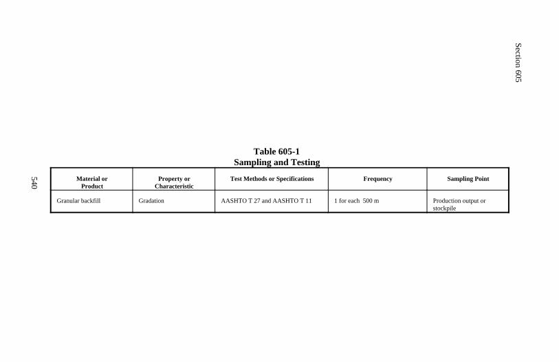
Section 605
540
Table 605-1Sampling and Testing
Material orProduct
Property orCharacteristic
Test Methods or Specifications Frequency Sampling Point
Granular backfill Gradation AASHTO T 27 and AASHTO T 11 1 for each 500 m Production output orstockpile
541
Section 606.) CORRUGATED METAL SPILLWAYS
Description
606.01 This work consists of furnishing and installing corrugated metalspillways.
Material
606.02 Conform to the following Section:
Culverts and drains 602
Construction Requirements
606.03 Placing Corrugated Metal Spillways. Spillway, inlet, outlet, andconnector dimensions and proportions may vary to permit the use of manu-facturer's standard jigs and templates.
Install spillway inlet assemblies as shown on the plans and consolidate theearth backfill by tamping.
Lay spillway outlet pipe according to Section 602. Anchor the spillway asshown on the plans.
606.04 Acceptance. Pipes, anchor assemblies, hardware, and other materialfurnished to fabricate metal spillways will be evaluated under Subsections106.02 and 106.03.
Excavation and backfill will be evaluated under Section 209.
Construction of spillways will be evaluated under Subsections 106.02 and106.04.
Measurement
606.05 Measure spillway assemblies and pipe anchor assemblies by the each.
Measure downdrain and outlet pipes under Section 602.

Section 606
542
Payment
606.06 The accepted quantities, measured as provided above, will be paid atthe contract price per unit of measurement for the pay items listed below thatare shown in the bid schedule. Payment will be full compensation for the workprescribed in this Section. See Subsection 109.05.
Payment will be made under:
Pay Item Pay Unit
60601 Spillway assembly Each60602 Pipe anchor assembly, ___ millimeter Each
543
Section 607.) CLEANING, RECONDITIONING, ANDREPAIRING EXISTING DRAINAGE STRUCTURES
Description
607.01 This work consists of cleaning, reconditioning, and repairing existingculverts and appurtenant structures.
Construction Requirements
607.02 General. Dispose of material according to Subsection 203.05.
607.03 Removing and Cleaning Culverts. Carefully remove the culvert andclean all foreign material from within the barrel and at the jointed ends.
607.04 Cleaning Culverts in Place. Remove and dispose of all foreignmaterial within the barrel and appurtenances of the culvert by any method thatdoes not damage the culvert.
All or part of a culvert designated to be cleaned in place may be removed,cleaned, and relayed according to Section 602.
607.05 Relaying or Stockpiling Salvaged Pipe. Relay removed and cleanedpipe according to Section 602. Furnish all jointing material and replacedamaged pipe according to Section 602.
Place salvaged pipe at a designated stockpile location. Dispose of pipe that isdamaged.
607.06 Reconditioning Drainage Structures. Remove all debris fromstructures designated to be reconditioned. Repair all leaks and structuraldamage and replace missing or broken metalwork according to Section 602.
607.07 Acceptance. Cleaning, reconditioning, and repairing existing drainagestructures will be evaluated under Subsection 106.02.
Relaying culverts will be evaluated under Section 602.
Section 607
544
Measurement
607.08 Measure removing, cleaning, and stockpiling culvert by the meter ofpipe in the stockpile.
Measure removing, cleaning, and relaying culvert by the meter along the invertof the culvert.
Measure cleaning culvert in place along the invert of the culvert. If the culvertis removed and relayed at the Contractor's option there is no additionalmeasurement.
Measure reconditioning drainage structures by the each.
Payment
607.09 The accepted quantities, measured as provided above, will be paid atthe contract price per unit of measurement for the pay items listed below thatare shown in the bid schedule. Payment will be full compensation for the workprescribed in this Section. See Subsection 109.05.
Payment will be made under:
Pay Item Pay Unit
60701 Removing, cleaning, and stockpiling culvert Meter60702 Removing, cleaning, and relaying culvert Meter60703 Cleaning culverts in place Meter60704 Reconditioning drainage structures Each
545
Section 608.) PAVED WATERWAYS
Description
608.01 This work consists of constructing paved ditches, gutters, spillways,and similar waterways not contiguous to the traveled way.
Paved waterways are designated as follows:
Type I Grouted rubbleType II Mortared rubbleType III Concrete and rubbleType IV ConcreteType V AsphaltType VI Placed riprap
Material
608.02 Conform to the following Sections and Subsections:
Asphalt mixtures 402Bed course 704.09Concrete 601Granular backfill 703.03(b)Mortar 712.05Reinforcing steel 709.01Riprap rock 705.02Rubble 620
Construction Requirements
608.03 General. Perform excavation and backfill work under Section 209.Place and compact bed course material. Compact the bed course with at leastthree passes of a lightweight mechanical tamper, roller, or vibratory system.Form the bed parallel to the finished surface of the waterway.
608.04 Grouted Rubble Paved Waterway. Embed pavement stones on thebed in a broken pattern with no continuous joint across the waterway or parallelto the flow line. Make the joints 25 to 50 millimeters wide. Place the stoneswith the flat faces up and the longest dimension at right angles to the centerlineof the waterway.
Section 608
546
Ram each stone until it is firm and reasonably true to the surface in grade,alignment, and cross-section. Remove and relay stone having an irregular oruneven surface.
Fill the joints with granular backfill to within 100 millimeters of the surface.Pour and broom mortar into the joints until the mortar is 13 millimeters belowthe surface. Clean the excess mortar from the surface.
608.05 Mortared Rubble Paved Waterway. Embed each pavement stonewith its flat face up and its longest dimension parallel to the gutter line. Placestones alternately so that there is not a continuous joint across the waterway orparallel to the flow line. Limit joint widths from 25 millimeters minimum to50 millimeters maximum.
Ram the stone until it is firm and reasonably true to the surface in grade,alignment, and cross-section.
Apply mortar to the exposed stone sides in such quantities that when theadjacent stone is placed and rammed into position, the mortar is within 13millimeters of the surface but not protruding above the surface. Clean theexcess mortar from the surface.
608.06 Concrete and Rubble Paved Waterway. Place the concrete foun-dation, reinforcing steel, and pavement stone in a progressive operation.Secure the reinforcing steel within the middle third of the depth of the concretefoundation. Clean and wet the pavement stone to near saturation. Embed the stone in the concrete foundation before it hardens. Place stonesalternately so there is not a continuous joint across the waterway or parallel tothe flow line. Limit joint widths from 25 millimeters minimum to 50millimeters maximum. Fill the joints between stones with mortar to 25millimeters below the top of the stone.
608.07 Concrete Paved Waterway. Perform the work according to Section601.
608.08 Asphalt Paved Waterway. Perform the work according to Section402. Before overlaying existing asphalt paved waterway, clean and seal thecracks according to Section 414.
Section 608
547
608.09 Placed Riprap Waterway. Use class I riprap. Perform the workaccording to Subsections 251.03 and 251.04.
608.10 Acceptance. Material for mortar will be evaluated under Subsec-tions 106.02 and 106.03. Mortar will be evaluated under Subsection 106.04.See Table 608-1 for sampling and testing requirements.
Bed course and granular backfill will be evaluated under Subsections 106.02and 106.04. See Table 608-1 for sampling and testing requirements.
Construction of paved waterways will be evaluated under Subsections106.02 and 106.04.
Excavation and backfill will be evaluated under Section 209.
Riprap will be evaluated under Section 251.
Asphalt mixture will be evaluated under Section 402.
Concrete will be evaluated under Section 601.
Rubble will be evaluated under Section 620.
Measurement
608.11 Measure paved waterways by the square meter, by the meter, or by themetric ton. Measure square meter width horizontally to include the total width.Measure the length parallel to the flow line.
Payment
608.12 The accepted quantities, measured as provided above, will be paid atthe contract price per unit of measurement for the pay items listed below thatare shown in the bid schedule. Payment will be full compensation for the workprescribed in this Section. See Subsection 109.05.

Section 608
548
Payment will be made under:
Pay Item Pay Unit
60801 Paved waterway type ___ Square meter60802 Paved waterway type ___ Meter60803 Asphalt paved waterway Metric ton
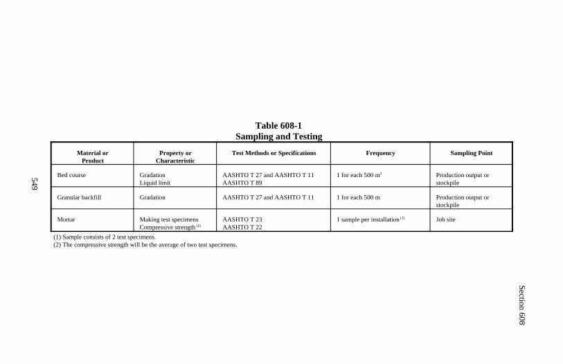
Section 608
549
Table 608-1Sampling and Testing
Material orProduct
Property orCharacteristic
Test Methods or Specifications Frequency Sampling Point
Bed course GradationLiquid limit
AASHTO T 27 and AASHTO T 11AASHTO T 89
1 for each 500 m3 Production output orstockpile
Granular backfill Gradation AASHTO T 27 and AASHTO T 11 1 for each 500 m Production output orstockpile
Mortar Making test specimensCompressive strength (2)
AASHTO T 23AASHTO T 22
1 sample per installation (1) Job site
(1) Sample consists of 2 test specimens.(2) The compressive strength will be the average of two test specimens.
550
Section 609.) CURB AND GUTTER
Description
609.01 This work consists of constructing or resetting of curb, combinationcurb and gutter, or wheelstops.
Stone curb is designated as type I or II according to Subsection 705.06.
Material
609.02 Conform to the following Sections and Subsections:
Asphalt mixtures 402Bed course 704.09Concrete 601Joint filler 712.01Mortar 712.05Precast concrete curbing 725.06Reinforcing steel 709.01Stone curbing 705.06
Construction Requirements
609.03 General. Perform excavation and backfill work under Section 209.Place and compact the bed course material. Compact the bed course with atleast three passes of a lightweight mechanical tamper, roller, or vibratory sys-tem.
609.04 Stone and Precast Concrete Curb. Clean the curb material thor-oughly and wet it just before setting. Set the curb in bed course so the face andtop lines are to line and grade. Make the joints 10 to 25 millimeters wide andfill the joints with mortar.
Complete the first 8 meters of curb to demonstrate the ability to build a curbmeeting these requirements. Do not continue construction until the 8-meter testsection is approved.
Where a concrete pavement is constructed contiguous to the curb, construct thejoints in the curb directly in line with the pavement expansion joints.
Section 609
551
Make the curb joint 19 millimeters wide and fill it with expansion joint fillerof the same nominal thickness as the pavement joint. Fill all voids between thejoint filler and the curb with mortar.
609.05 Portland Cement Concrete Curb or Curb and Gutter. Performwork according to Section 601. The curb or curb and gutter may be cast-in-place or slip-formed.
(a) Cast-in-place. Use forms that extend for the full depth of the concrete.Use curved forms for curb with a radius of 90 meters or less.
(1) Contraction joints. Construct curb in sections of uniform 3 meterlengths. Construct contraction joints 3 millimeters wide. Use metal di-vider plates. When the curb is constructed adjacent to or on concretepavement, match the contraction joints in the pavement.
(2) Expansion joints. Form expansion joints at intervals of 18 metersusing a 19-millimeter thick preformed expansion joint filler. Where thecurb is constructed adjacent to or on concrete pavement, match the expan-sion joints in the pavement.
Finish the concrete smooth and even with a wood float. Broom finish paral-lel to the curb line according to Subsection 552.14(c)(2). When an exposedaggregate finish is required, finish according to Subsection 552.14(c)(4).Leave forms in place for 24 hours or until the concrete has set sufficiently sothe forms can be removed without harming the curb.
(b) Slip-formed. Use a self-propelled automatic curb machine or a paverwith curb attachments. Use a machine that is heavy enough to obtain con-solidation without the machine riding above the foundation.
Adjust the concrete aggregate gradation, if necessary, to produce a curb orcurb and gutter that has well-defined web marks of water on the surface.Remove and replace sections with craters larger than 5 millimeters or othersections determined to be damaged or defective. Repairing surface cratersand other defective sections by plastering is not permitted.
After the concrete has hardened sufficiently to permit sawing without damag-e, saw contraction joints according to (a)(1) above. Construct expansionjoints according to (a)(2) above.
Section 609
552
609.06 Asphalt Concrete Curb. Where curb is constructed on a pavement,place a tack coat according to Section 412 on the area under the curb.
Construct asphalt concrete curb according to Section 402. Use a self-propelledautomatic curb machine or a paver with curb attachments that is heavy enoughto compact a curb without riding above the foundation. Make the curb uniformin texture, shape, and density. Curb may be constructed by other means onlyin short sections or sections with short radii. 609.07 Resetting Stone or Precast Concrete Curb. Carefully remove, clean,and store the curb. Cut or fit the curb as necessary for installation. Replace alllost, damaged, or destroyed curb. Reset the curb according to Subsection609.04.
609.08 Wheelstops. Pin the wheelstops in place with two 1-meter sections of20M reinforcing steel or 19-millimeter steel rods. Reset wheelstops in thesame manner.
609.09 Acceptance. Material for mortar will be evaluated under Subsec-tions 106.02 and 106.03. Mortar will be evaluated under Subsection 106.04.See Table 609-1 for sampling and testing requirements.
Precast units (curb and wheel stops) will be evaluated under Subsections106.02 and 106.03.
Bed course material will be evaluated under Subsections 106.02 and 106.04.See Table 609-1 for sampling and testing requirements,
Stone for stone curbing will be evaluated under Subsections 106.02 and106.04.
Construction of curb and gutter, and wheelstops will be evaluated under Sub-sections 106.02 and 106.04.
Excavation and backfill will be evaluated under Section 209.
Asphalt mixture will be evaluated under Section 402.
Concrete will be evaluated under Section 601.
Section 609
553
Measurement
609.10 Measure curb and combination curb and gutter, both new and reset, bythe meter along the front face of the curb. Make no deduction in length fordrainage structures installed in the curb section or for driveway and handicapaccess ramp openings where the gutter is carried across.
Measure wheelstops, both new and reset, by the each.
Measure bed course material by the metric ton or by the cubic meter in place.
Payment
609.11 The accepted quantities, measured as provided above, will be paid atthe contract price per unit of measurement for the pay items listed below thatare shown in the bid schedule. Payment will be full compensation for the workprescribed in this Section. See Subsection 109.05.
Payment will be made under:
Pay Item Pay Unit
60901 Portland cement concrete curb, Meter___ millimeter depth
60902 Portland cement concrete curb and Metergutter, ___ millimeter depth
60903 Stone curb type ___, ___ millimeter depth Meter60904 Precast concrete curb Meter60905 Asphalt concrete curb, ___ millimeter depth Meter60906 Reset curb Meter60907 Bed course material Cubic meter60908 Bed course material Metric ton60909 Wheelstop Each60910 Remove and reset wheelstop Each
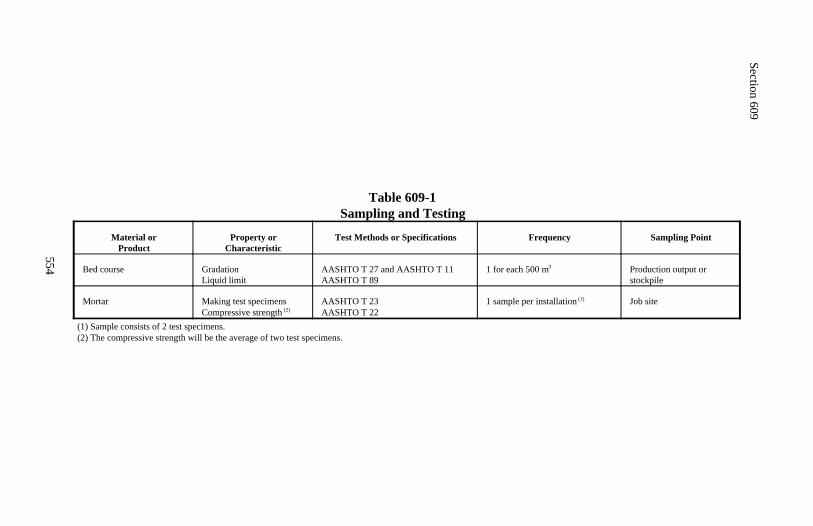
Section 609
554
Table 609-1Sampling and Testing
Material orProduct
Property orCharacteristic
Test Methods or Specifications Frequency Sampling Point
Bed course GradationLiquid limit
AASHTO T 27 and AASHTO T 11AASHTO T 89
1 for each 500 m3 Production output orstockpile
Mortar Making test specimensCompressive strength (2)
AASHTO T 23AASHTO T 22
1 sample per installation (1) Job site
(1) Sample consists of 2 test specimens.(2) The compressive strength will be the average of two test specimens.
555
Section 610.) HORIZONTAL DRAINS
Description
610.01 This work consists of constructing horizontal drains including collectorsystems when specified.
Material
610.02 Conform to the following Subsections:
Metallic-coated corrugated steel pipe 707.02Polyethylene (PE) pipe 725.16Polyvinyl chloride (PVC) pipe 725.15Steel pipe 717.06
Construction Requirements
610.03 General. Furnish pipe and fittings of one material shown in Subsec-tion 610.02. Furnish slotted pipe with 2 rows of slots cut circumferentially inthe pipe on 2 of the third points that are 120 degrees apart. Make the width ofthe slots 0.5 millimeter with the total slot opening equal to 4200 square milli-meters per meter of pipe.
610.04 Drilling Holes. The locations for installing horizontal drains as shownon the plans are approximate. The exact locations will be determined in thefield.
Drill holes with rotary equipment capable of drilling 75 to 150-millimeterdiameter holes through soil and rock. Determine the elevation at the upper endof the completed horizontal drain hole by inserting tubes or pipes and measur-ing liquid levels, or by other satisfactory means. Dispose of drilling water ina manner that does not contaminate surface watercourses.
610.05 Installing Horizontal Drain. Tightly plug the entrance end of theslotted pipe with a rounded or pointed extension that does not extend more than150 millimeters beyond the end of the pipe. Insert the pipe inside the drill rodwith the slots up. Retract the drill rod so the drilled hole is fully cased with theslotted pipe. Connect additional pipe as necessary to form a continuous tube.
Section 610
556
Use unslotted pipe for the last 3 to 6 meters of the outlet end. Seal the spacebetween the drilled hole and the unslotted pipe for at least 3 meters at the outletend with an approved impermeable material. Do not seal the space betweenthe drilled hole and the slotted pipe.
610.06 Installing Outlet Drains and Collector Systems. Attach outlet drainpipe to the ends of all horizontal drains by means of a tee or street ell. Installa collector system of the type, kind, and size detailed in the contract.
610.07 Acceptance. Material furnished for horizontal drains will be evaluatedunder Subsections 106.02 and 106.03.
Construction of horizontal drains will be evaluated under Subsections106.02 and 106.04.
Measurement
610.08 Measure horizontal drain pipe, including the length of the outlet pipe,by the meter.
Measure the collector system by the meter or lump sum.
Payment
610.09 The accepted quantities, measured as provided above, will be paid atthe contract price per unit of measurement for the pay items listed below thatare shown in the bid schedule. Payment will be full compensation for the workprescribed in this Section. See Subsection 109.05.
Payment will be made under:
Pay Item Pay Unit
61001 Horizontal drain pipe Meter61002 Collector system Meter61003 Collector system Lump sum
557
Section 611.) WATER SYSTEMS
Description
611.01 This work consists of constructing or reconstructing water systems.
Material
611.02 Conform to the following Section and Subsections:
Bedding material 704.02Cast iron soil pipe and fittings 725.17Concrete 601Polyvinyl chloride (PVC) pipe and fittings 725.15Seamless copper water tube and fittings 725.18Steel pipe and fittings 717.06
Construction Requirements
611.03 General. Furnish material and workmanship conforming to the stan-dards of APWA, the AWWA, National Building Code, and local plumbing andsafety codes.
At the preconstruction conference, submit a certified cost breakdown of theindividual items involved in the lump sum item for use in making progresspayments and price adjustments.
Obtain permits, arrange for inspections, and pay all fees necessary to obtainwater service.
Perform excavation and backfill work under Section 209. Bed the pipe accord-ing to Subsection 209.09(b)(2).
611.04 Laying Waterline. Where it is necessary to cross a waterline over asewer line, construct the waterline a minimum vertical distance of 450 millime-ters above the sewer line.
Inspect each joint or fixture and clean the interior of the pipe before placing inthe trench. Do not allow dirt, water, rodents, or other contaminants to enterthe pipe during installation. Center and push each joint completely home,and fasten the joint according to the manufacturer's recommendations.
Section 611
558
Brace major fixtures or fixtures that could blow off the line under pressure witha cast-in-place concrete wedge block. Cast the block between the fixture andthe undisturbed vertical trench wall with a minimum bearing surface of 0.2square meters against the vertical wall. Do not pressure test lines until concretehas established its required strength.
611.05 Testing and Disinfecting Lines. Test all joints under pressure beforebackfilling. Repair all leaks.
Disinfect all lines that are to carry water for human consumption. Fill the lineswith a water solution containing a residual chlorine level of at least 50 parts permillion for at least 24 hours. Drain and flush the line after the disinfectingperiod. Do not dispose of disinfectant water in live streams.
611.06 Backfilling. Backfill according to Subsection 209.10, except handplace the backfill to 300 millimeters over the top of the pipe. Remove all rocksand hard lumps from the hand-placed layer.
During backfilling, place a plastic locator strip approximately 300 millimetersabove the pipe. If nonmetallic waterline is installed, use a locator strip contain-ing metal that allows detection with a metal detector. Hold hydrants, valveboxes, and other vertical fixtures vertical with the tops adjusted to the requiredelevation.
611.07 Acceptance. Material for water systems will be evaluated underSubsections 106.02 and 106.03.
Installation of water systems will be evaluated under Subsections 106.02 and106.04.
Excavation and backfill will be evaluated under Section 209.
Measurement
611.08 Measure water systems by the lump sum.
Measure waterlines and encasement pipes by the meter with no deduction forthe length through tees, bends, valves, or other fixtures.
Measure valves, valve boxes, and fire hydrants by the each.
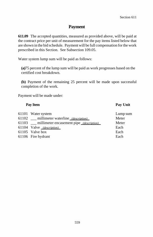
Section 611
559
Payment
611.09 The accepted quantities, measured as provided above, will be paid atthe contract price per unit of measurement for the pay items listed below thatare shown in the bid schedule. Payment will be full compensation for the workprescribed in this Section. See Subsection 109.05.
Water system lump sum will be paid as follows:
(a) 75 percent of the lump sum will be paid as work progresses based on thecertified cost breakdown.
(b) Payment of the remaining 25 percent will be made upon successfulcompletion of the work.
Payment will be made under:
Pay Item Pay Unit
61101 Water system Lump sum61102 ___ millimeter waterline (description) Meter61103 ___ millimeter encasement pipe (description) Meter61104 Valve (description) Each61105 Valve box Each61106 Fire hydrant Each
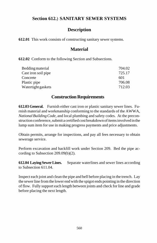
560
Section 612.) SANITARY SEWER SYSTEMS
Description
612.01 This work consists of constructing sanitary sewer systems.
Material
612.02 Conform to the following Section and Subsections.
Bedding material 704.02Cast iron soil pipe 725.17Concrete 601Plastic pipe 706.08Watertight gaskets 712.03
Construction Requirements
612.03 General. Furnish either cast iron or plastic sanitary sewer lines. Fu-rnish material and workmanship conforming to the standards of the AWWA,National Building Code, and local plumbing and safety codes. At the precon-struction conference, submit a certified cost breakdown of items involved in thelump sum item for use in making progress payments and price adjustments.
Obtain permits, arrange for inspections, and pay all fees necessary to obtainsewerage service.
Perform excavation and backfill work under Section 209. Bed the pipe ac-cording to Subsection 209.09(b)(2).
612.04 Laying Sewer Lines. Separate waterlines and sewer lines accordingto Subsection 611.04.
Inspect each joint and clean the pipe and bell before placing in the trench. Laythe sewer line from the lower end with the spigot ends pointing in the directionof flow. Fully support each length between joints and check for line and gradebefore placing the next length.
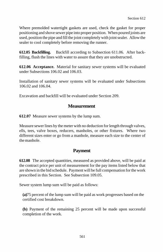
Section 612
561
Where premolded watertight gaskets are used, check the gasket for properpositioning and shove sewer pipe into proper position. When poured joints areused, position the pipe and fill the joint completely with joint sealer. Allow thesealer to cool completely before removing the runner.
612.05 Backfilling. Backfill according to Subsection 611.06. After back-filling, flush the lines with water to assure that they are unobstructed.
612.06 Acceptance. Material for sanitary sewer systems will be evaluatedunder Subsections 106.02 and 106.03.
Installation of sanitary sewer systems will be evaluated under Subsections106.02 and 106.04.
Excavation and backfill will be evaluated under Section 209.
Measurement
612.07 Measure sewer systems by the lump sum.
Measure sewer lines by the meter with no deduction for length through valves,ells, tees, valve boxes, reducers, manholes, or other fixtures. Where twodifferent sizes enter or go from a manhole, measure each size to the center ofthe manhole.
Payment
612.08 The accepted quantities, measured as provided above, will be paid atthe contract price per unit of measurement for the pay items listed below thatare shown in the bid schedule. Payment will be full compensation for the workprescribed in this Section. See Subsection 109.05.
Sewer system lump sum will be paid as follows:
(a) 75 percent of the lump sum will be paid as work progresses based on thecertified cost breakdown.
(b) Payment of the remaining 25 percent will be made upon successfulcompletion of the work.

Section 612
562
Payment will be made under:
Pay Item Pay Unit
61201 Sewer system Lump sum61202 ___ millimeter sewer line (description) Meter
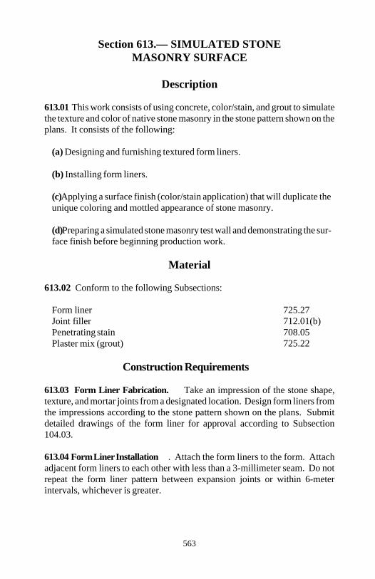
563
Section 613.— SIMULATED STONEMASONRY SURFACE
Description
613.01 This work consists of using concrete, color/stain, and grout to simulatethe texture and color of native stone masonry in the stone pattern shown on theplans. It consists of the following:
(a) Designing and furnishing textured form liners.
(b) Installing form liners.
(c) Applying a surface finish (color/stain application) that will duplicate theunique coloring and mottled appearance of stone masonry.
(d) Preparing a simulated stone masonry test wall and demonstrating the sur-face finish before beginning production work.
Material
613.02 Conform to the following Subsections:
Form liner 725.27Joint filler 712.01(b)Penetrating stain 708.05Plaster mix (grout) 725.22
Construction Requirements
613.03 Form Liner Fabrication. Take an impression of the stone shape,texture, and mortar joints from a designated location. Design form liners fromthe impressions according to the stone pattern shown on the plans. Submitdetailed drawings of the form liner for approval according to Subsection104.03.
613.04 Form Liner Installation . Attach the form liners to the form. Attachadjacent form liners to each other with less than a 3-millimeter seam. Do notrepeat the form liner pattern between expansion joints or within 6-meterintervals, whichever is greater.
Section 613
564
Form expansion joints at the intervals shown on the plans. Blend the butt jointsinto the pattern and the final concrete surface.
Coordinate the forms with wall ties. Place form tie holes in the high point ofrustication or in the mortar joint.
Clean off build-up before reusing form liners. Visually inspect each liner forblemishes and tears. Repair the liner before installation. 613.05 Top Surface. Emboss the plastic concrete in the exposed top surfaceby stamping, tooling, troweling, hand shaping, or combination thereof, tosimulate the stone masonry texture and mortared joints. Match the side patternof the formed mortared joints. Immediately after the free surface waterevaporates and the finish embossing is complete, cure the concrete for 7 daysaccording to Subsection 552.15(b). Do not use liquid membrane curingcompounds.
613.06 Form Liner Removal. Within 24 hours after placing concrete,remove or break free the form liners without causing concrete surface dete-rioration or weakness in the substratum. Remove all form tie material to adepth of at least 25 millimeters below the concrete face without spalling anddamaging the concrete.
Cure the concrete for 7 days according to Subsection 552.15(b). Do not useliquid membrane curing compounds.
613.07 Preparation of Concrete Surface. Finish all exposed formedconcrete surfaces according to Subsection 552.16(a). Finish so that verticalseams, horizontal seams, and butt joint marks are not visible. Minimize grind-ing and chipping to avoid exposing aggregate.
Provide a completed surface free of blemishes, discolorations, surface voids,and conspicuous form marks. Make the finished texture and patterns continu-ous without visual disruption.
613.08 Color/Stain Application. Age concrete, including patches, a mini-mum of 30 days. Clean the surface of all latency, dirt, dust, grease, and anyforeign material by approved methods.
Section 613
565
Remove efflorescence with a pressure water wash. Use a fan nozzle heldperpendicular to the surface at a distance between 0.6 and 1 meter. Use aminimum 20-megapascal water pressure at a rate of 12 to 16 liters per minute.Do not sand blast surfaces that receive color/stain.
Correct all surface irregularities created by the surface cleaning.
Maintain the concrete temperature between 4 and 30 C when applyingcolor/stain and for 48 hours after applying color/stain.
Color/stain all exposed concrete surfaces. Use a color/stain applicationsuitable to obtain the appearance of the native stone masonry. Use a minimumof 3 colors/stains.
When required at boundaries between two color tones or between surfacesreceiving color at different times, take care and provide protection to avoidover-spray and color overlap.
Apply grout of a natural cement color to each form joint. Use sufficient groutso the over-spray of the color/stain is not visible. Give the form pattern groutjoint the appearance of mortared joints in completed masonry. Recoat all areas inconsistent with the approved test wall.
Treat expansion joints with caulk/grout to blend with the appearance of theadjacent stone or mortar joint.
613.09 Test Wall. Before production work on the simulated stone masonry,construct a 1-meter high, by 0.5-meter wide, by 3 meter-long test wall accord-ing to Section 552 and these specifications.
Cast the test wall on site, using the same forming methods, procedures, formliner, texture configuration, expansion joint, concrete mixture, and color/stainapplication proposed for the production work. Demonstrate the quality andconsistency of joint treatment, end treatment, top embossing methods, backtreatment, and color/stain application on the test wall. If a test wall isunacceptable, construct a new test wall.
Begin production structural concrete work only after the test wall is approved.Begin production color/stain application only after the color/stain applicationon the test wall is approved. Dispose of the test wall after use.
Section 613
566
613.11 Acceptance. Material for simulated stone masonry surface treatmentwill be evaluated under Subsections 106.02 and 106.03.
Installation of form liners will be evaluated under Subsections 106.02 and106.04.
Application of color/stain to all exposed concrete surfaces will be evaluatedunder Subsection 106.02.
Construction of the simulated stone masonry test wall will be evaluated underSubsection 106.02.
Measurement
613.11 Measure simulated stone masonry surface treatment by the squaremeter.
Measure simulated stone masonry test wall including concrete and surfacefinish by the each.
Do not measure form liners for payment.
Payment
613.12 The accepted quantities, measured as provided above, will be paid atthe contract price per unit of measurement for the pay items listed below thatare shown on the bid schedule. Payment will be full compensation for the workprescribed in this Section. See Subsection 109.05.
Payment will be made under:
Pay Item Pay Unit
61301 Simulated stone masonry surface treatment Square meter61302 Simulated stone masonry test wall Each
567
Section 614.) LEAN CONCRETE BACKFILL
Description
614.01 This work consists of constructing lean concrete backfill.
Material
614.02 Conform to the following Subsections:
Aggregate 703.16Portland cement 701.01Water 725.01
Construction Requirements
614.03 Composition of Mix. Furnish an aggregate which is uniformly gradedfrom coarse to fine, has a maximum size of 25 millimeters, and has no morethan 10 percent passing the 75-micrometer sieve.
Proportion aggregate, cement, and water by mass or volume.
Furnish lean concrete backfill which contains 110 to 113 kilograms of cementper cubic meter.
Submit the following:
(a) Type and source(s) of aggregates(b) Type and source of cement(c) Scale mass or quantity of each aggregate proposed per cubic meter oflean concrete backfill(d) Quantity of water proposed per cubic meter of lean concrete backfill(e) Quantity of cement proposed per cubic meter of lean concrete backfill(f) Slump
614.04 General. Perform the work described under Section 209.
Do not place lean concrete backfill in contact with aluminum or aluminum-coated structures.
Do not use lean concrete backfill above the top of subgrade.
Section 614
568
614.05 Mixing and Placing Lean Concrete Backfill. Mix lean concretebackfill by pugmill, rotary drum, or other approved mixer to obtain a uniformmix.
Place lean concrete backfill in a uniform manner that prevents voids in orsegregation of the backfill. Place lean concrete backfill in horizontal layers notexceeding 300 millimeters in thickness.
When backfilling around culverts and other structures, place lean concretebackfill in a manner which will not float or shift the structure. Bring thebackfill up evenly on all sides of the structure.
When placing lean concrete backfill at or below an atmospheric temperatureof 2 C, perform the work under Subsection 552.10(a).
Wait at least 4 hours before backfilling over lean concrete backfill.
614.06 Acceptance. Material for lean concrete backfill will be evaluatedunder Subsections 106.02 and 106.03.
Lean concrete backfilling will be evaluated under Subsection 106.02.
Measurement
614.07 Measure lean concrete backfill by the cubic meter in the haulingvehicle.
Payment
614.08 The accepted quantities, measured as provided above, will be paid atthe contract price per unit of measurement for the pay item listed below that isshown in the bid schedule. Payment will be full compensation for the workprescribed in this Section. See Subsection 109.05.
Payment will be made under:
Pay Item Pay Unit
61401 Lean concrete backfill Cubic meter
569
Section 615.) SIDEWALKS, DRIVE PADS,AND PAVED MEDIANS
Description
615.01 This work consists of constructing sidewalks, drive pads, and pavedmedians.
Sidewalks, drive pads, and paved medians are designated as concrete, asphalt,concrete brick, or clay brick.
Material
615.02 Conform to the following Sections and Subsections:
Asphalt mixtures 402Bed course 704.09Clay or shale brick 725.07Concrete 601Concrete brick 725.08Curing material 711.01Joint fillers 712.01Reinforcing steel 709.01
Construction Requirements
615.03 General. Perform excavation and backfill work under Section 209.Place bed course material in layers not exceeding 100 millimeters in compactedthickness. Compact each layer with at least three passes of a lightweight me-chanical tamper, roller, or vibratory system.
615.04 Portland Cement Concrete Sidewalks, Drive Pads, and Medians.Perform the work according to Section 601. Use forms which extend for thefull depth of the concrete.
(a) Joints. Construct joints perpendicular to the outside slab edges and otherjoints. Match the joints in adjacent curb or pavements. Tool and remove allfree mortar and concrete from joints.
Section 615
570
(1) Expansion joints. Construct at intervals not exceeding 18 meters.Use 19-millimeter thick preformed expansion joint filler for the full depthof the joints.
(2) Contraction joints. Construct at intervals not exceeding 3 meters.Form the joint with a jointing tool or saw the joints to a depth of 1/4 to1/3 of the thickness of the concrete and about 3 millimeters wide.
(3) Construction joints. Form construction joints around all appurte-nances such as manholes, utility poles, buildings, and bridges. Use 13-millimeter thick preformed expansion joint filler for the full depth of thejoints.
(b) Finishes. Provide a sidewalk finish unless otherwise required. Edgeoutside edges of slab and all joints with a 6-millimeter radius edging tool.
(1) Sidewalk finish. See Subsection 552.14(c)(2).
(2) Exposed aggregate finish. See Subsection 552.14(c)(4).
Cure the concrete for at least 72 hours according to Subsection 552.15(b) or(c). Protect the work from pedestrian traffic for 72 hours and from vehiculartraffic for 7 days.
615.05 Asphalt Concrete Sidewalks, Drive Pads, and Medians. Performthe work according to Section 402.
615.06 Brick Sidewalks, Drive Pads, and Medians. Lay brick in successivecourses on a prepared surface. Lay each course of brick to grade. Relay anycourse that deviates from a straight line by more than 55 millimeters in 10meters.
Sweep and inspect the brick surface before the bed sets. Remove each imper-fect brick and replace.
Chock the joints flush with a dry mixture of 4 parts sand and 1 part cement bymass and carefully water the surface to saturate the joint filler.
Section 615
571
615.07 Acceptance. Clay or shale brick, concrete brick, curing material, jointfillers, and reinforcing steel will be evaluated under Subsections 106.02and 106.03.
Bed course material will be evaluated under Subsections 106.02 and 106.04.See Table 615-1 for sampling and testing requirements.
Construction of sidewalks, drive pads, and medians will be evaluated underSubsections 106.02 and 106.04.
Excavation and backfill will be evaluated under Section 209.
Asphalt mixture will be evaluated under Section 402.
Concrete will be evaluated under Section 601.
Measurement
615.08 Measure sidewalks, drive pads, and paved medians by the squaremeter.
Payment
615.09 The accepted quantities, measured as provided above, will be paid atthe contract price per unit of measurement for the pay items listed below thatare shown in the bid schedule. Payment will be full compensation for the workprescribed in this Section. See Subsection 109.05.
Payment will be made under:
Pay Item Pay Unit
61501 ________ sidewalk Square meter61502 ________ drive pad Square meter61503 ________ median Square meter
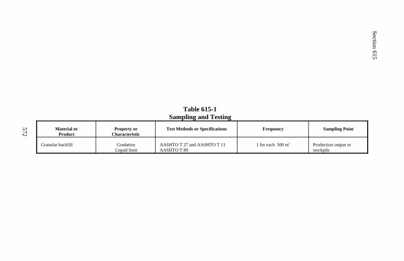
Section 615
572
Table 615-1Sampling and Testing
Material orProduct
Property orCharacteristic
Test Methods or Specifications Frequency Sampling Point
Granular backfill GradationLiquid limit
AASHTO T 27 and AASHTO T 11AASHTO T 89
1 for each 500 m3 Production output orstockpile
573
Section 616.) SLOPE PAVING
Description
616.01 This work consists of constructing concrete, brick, masonry block,rubble, or cellular concrete block slope paving.
Material
616.02 Conform to the following Sections and Subsections:
Bed course 704.09Cellular concrete blocks 725.10Concrete 601Concrete brick 725.08Concrete masonry blocks 725.09Geotextile type IV 714.01Mortar 712.05Rubble 620Welded steel wire fabric 709.01(h)
Construction Requirements
616.03 General. Perform excavation and backfill work under Section 209.Place and compact bed course material with at least three passes of a light-weight mechanical tamper, roller, or vibratory system.
616.04 Geotextile. When required by the contract, place geotextile accordingto Subsection 207.05. Bury the ends of the geotextile for anchorage. Pin thestrips at 1.5-meter intervals to hold the geotextile lap in place until slope pav-ing is placed. Replace or repair all geotextile that is torn or punctured.
616.05 Concrete Slope Paving. Construct toe walls. Place welded wirefabric at the center of slab. Run the welded steel wire fabric continuouslythrough the joints. Lap adjacent runs of fabric by at least 150 millimeters.
Section 616
574
Perform concrete work according to Section 601. Place slabs starting at thebottom of the slope. Construct horizontal joints parallel to the bottom of theslope and the vertical joints perpendicular to the horizontal joints. Constructcold joints without filler.
Finish the surface with a sidewalk finish according to Subsection552.14(c)(2). Edge the outside edges of the slab and all joints with a6-millimeter radius edging tool.
616.06 Brick, Masonry Block, or Rubble Slope Paving. Place bricks, ma-sonry blocks, or rubble starting at the bottom of the slope. Place them on thefoundation bed with flat faces up and the longest dimension parallel to thebottom of the slope.
Ram each brick, masonry block, or stone into place. Apply mortar on theexposed side in such quantities that when the adjacent brick, masonry block,or stone is placed and rammed into position, the mortar is within 13 millimetersof the surface and not protruding above the top. Make the brick and masonryblock joints 13 millimeters wide or less and rubble joints 25 millimeters or less.Clean all mortar stain from the surface.
616.07 Cellular Concrete Block Slope Paving. Place the blocks starting ina trench or against a suitable anchorage at the bottom of the slope. Lay eachblock perpendicular to the slope and bed firmly against adjoining blocks.Grout to fill misaligned joints or breaks at slope changes. Do not grout indi-vidual blocks to each other.
Spread topsoil loosely over the cellular block slope paving, partially filling thecell openings. When required by the contract, establish turf according to Sec-tion 625.
616.08 Acceptance. Cellular concrete blocks, concrete brick, concrete ma-sonry blocks, material for mortar, and welded steel wire fabric will be evalu-ated under Subsections 106.02 and 106.03.
Mortar will be evaluated under Subsections 106.02 and 106.04. See Table616-1 for sampling and testing requirements.
Bed course material will be evaluated under Subsections 106.02 and 106.04.See Table 616-1 for sampling and testing requirements.
Section 616
575
Slope paving construction will be evaluated under Subsections 106.02 and106.04.
Geotextile will be evaluated under Section 207.
Excavation and backfill will be evaluated under Section 209.
Concrete will be evaluated under Section 601.
Rubble will be evaluated under Section 620.
Topsoil will be evaluated under Section 624.
Turf will be evaluated under Section 625.
Measurement
616.09 Measure slope paving by the square meter.
Measure topsoil under Section 624.
Measure turf establishment under Section 625.
Payment
616.10 The accepted quantities, measured as provided above, will be paid atthe contract price per unit of measurement for the pay item listed below that isshown in the bid schedule. Payment will be full compensation for the workprescribed in this Section. See Subsection 109.05.
Payment will be made under:
Pay Item Pay Unit
61601 Concrete slope paving Square meter61602 Brick slope paving Square meter61603 Masonry block slope paving Square meter61604 Rubble slope paving Square meter61605 Cellular concrete block slope paving Square meter
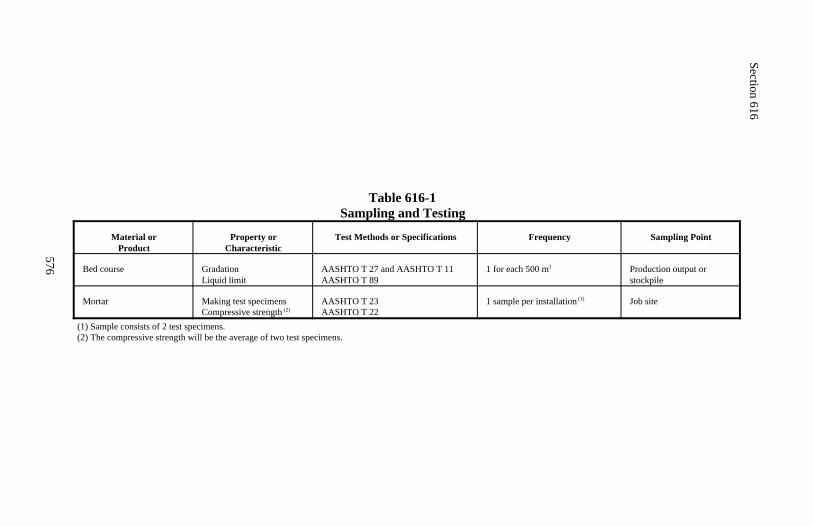
Section 616
576
Table 616-1Sampling and Testing
Material orProduct
Property orCharacteristic
Test Methods or Specifications Frequency Sampling Point
Bed course GradationLiquid limit
AASHTO T 27 and AASHTO T 11AASHTO T 89
1 for each 500 m3 Production output orstockpile
Mortar Making test specimensCompressive strength (2)
AASHTO T 23AASHTO T 22
1 sample per installation (1) Job site
(1) Sample consists of 2 test specimens.(2) The compressive strength will be the average of two test specimens.
577
Section 617.) GUARDRAIL
Description
617.01 This work consists of constructing guardrail systems and modifying,removing, resetting, and raising existing guardrail systems.
(a) Guardrail systems are designated as follows:
G1 Cable guardrailG2 W-beam (weak post)G3 Box beamG4 Blocked-out W beam standard barrierG9 Blocked-out thrie beam standard barrierMB4 Blocked-out W beam median barrierSBTA Steel-backed timber guardrail/timber posts and block-outSBTB Steel-backed timber guardrail/timber posts and no block-outCRT W-beam guardrail and no blockoutSBLG Steel-backed log rail
(b) Steel guardrail types are designated as follows:
I Zinc-coated, 550 grams per square meterII Zinc-coated, 1100 grams per square meterIII Painted railsIV Corrosion resistant steel
(c) Steel guardrail classes are designated as follows:
A Metal thickness - 2.67 millimetersB Metal thickness - 3.43 millimeters
(d) Terminal section types are designated as follows:
BCT Breakaway cable terminalCRT Cable releasing terminalMELT Modified eccentric loader terminalG4-BAT Back slope anchor terminal
Section 617
578
Material
617.02 Conform to the following Section and Subsections:
Box beam rail 710.07Concrete 601Corrosion resistant steel rail 710.06(b)Galvanized steel rail 710.06(a)Guardrail hardware 710.10Guardrail posts 710.09Precast anchors 725.11Reflector tabs 710.10Retroreflective sheeting type I or type II 718.01Steel-backed timber rail 710.08Welding 555.03Wire rope or wire cable 709.02Wood preservative treatment 716.03
Construction Requirements
617.03 Posts. When pavement is within 1 meter of the guardrail, set postsbefore placing the pavement.
Do not shorten guardrail posts unless the cut end is set in concrete. Do notshorten posts in terminal sections.
If an impenetrable object is encountered while placing posts, enlarge the holeto provide not less than 150 millimeters clearance on all sides, and to aminimum depth of 0.75 meters. Set the post in concrete to within 150millimeters of the top of the hole. Backfill and compact the remaining 150millimeters with acceptable material.
Drive posts into pilot holes that are punched or drilled. The dimensions of thepilot hole shall not exceed the dimensions of the post by more than 15millimeters. Set posts plumb, backfill, and compact.
When longer posts are specified, do not use them in the terminal sections.
Section 617
579
Stamp the post length on the top of all wood posts. Restamp numbers dis-turbed during installation. Stamp post length on all metal posts. Galvanizeafter stamping.
Alternate hole arrangements do not apply to posts in anchorage assemblies.
617.04 Rail Elements. Install the rail elements after the pavement adjacentto the guardrail is complete. Do not modify specified hole diameters or slot di-mensions.
(a) Steel rail. Shop bend all curved guardrail with a radius of 45 meters orless.
Erect rail elements in a smooth continuous line with the laps in the directionof traffic flow. Use bolts that extend at least 6 millimeters but not more than25 millimeters beyond the nuts. Tighten all bolts.
Paint all scrapes on galvanized surfaces that are through to the base metalwith 2 coats of zinc-oxide paint.
(b) Timber rail. Equally space bolts along the front face of the timber railto match the holes in the steel backing. Align timber guardrail along the topand front edges of the rail.
Field cut timber rails to produce a close fit at joints. Treat field cuts with 2coats of chromated copper arsenate.
(c) Log rail. Construct log rail according to the plans.
617.05 Terminal Sections. Construct terminal sections at the locationsshown. Terminal sections consist of posts, railing, hardware, and anchorageassembly necessary to construct the type of terminal section specified.
Where concrete anchors are installed, construct either cast-in-place or precastunits. Do not connect the guardrail to cast-in-place anchors until the concretehas cured 7 days. Install end anchor cables tightly without slack. Use either the steel tube anchor or the concrete anchor in the construction ofthe anchorage assembly for the type BCT terminal section.
Section 617
580
When required by the contract, construct earth berms according to Section 204.
617.06 Connection to Structure. Construct connection to structure and,where required by the contract, reinforced concrete transition according to theplans.
617.07 Removing and Resetting Guardrail. Remove and store the existingguardrail, posts, and appurtenances. Remove and dispose of posts that are setin concrete. Replace all guardrail, posts, and hardware damaged duringremoval, storage, or resetting. Backfill all holes resulting from the removal ofguardrail posts and anchors with granular material according to Section 209.
617.08 Raising Guardrail. Remove the existing guardrail and appurtenances.Replace and reset posts as needed. Replace all guardrail, posts, and hardwaredamaged during the removal and raising.
617.09 Acceptance. Material for guardrail will be evaluated under Sub-sections 106.02 and 106.03.
Construction of guardrail will be evaluated under Subsections 106.02 and106.04.
Earth berm construction will be evaluated under Section 204.
Structural excavation will be evaluated under Section 209.
Welding will be evaluated under Section 555.
Concrete will be evaluated under Section 601.
Measurement
617.10 Measure guardrail, except steel-backed timber guardrail and steel-backed log rail, by the meter along the face of the rail excluding terminalsections. Measure steel-backed timber guardrail and steel-backed log rail bythe meter along the face of the rail including terminal sections. Measuretransition sections from G9 rail to G4 rail as G9 rail.
Section 617
581
Measure terminal sections by the each, except measure the following terminalsections as a part of the rail:
(a) Steel-backed timber guardrail terminal sections(b) Steel-backed log rail terminal sections(c) BCT anchorage assemblies constructed as a part of the CRT system
Measure removing and resetting guardrail and raising guardrail by the meteralong the face of the rail including reset terminal sections. Measure replacement posts (except replacement posts for posts damaged byconstruction operations) used in the removing, resetting, or raising guardrail bythe each.
Measure connection to structure by the each.
Measure reinforced concrete transitions by the each.
Measure earth berms under Section 204.
Payment
617.11 The accepted quantities, measured as provided above, will be paid atthe contract price per unit of measurement for the pay items listed below thatare shown in the bid schedule. Payment will be full compensation for the workprescribed in this Section. See Subsection 109.05.
Payment will be made under:
Pay Item Pay Unit
61701 Guardrail system ____, type ___, class ___ Meter61702 Terminal section type ___ Each61703 Removing and resetting guardrail Meter61704 Raising guardrail Meter61705 Replacement posts Each61706 Connection to structure Each61707 Reinforced concrete transition Each
Section 618
582
Section 618.) CONCRETE BARRIERS ANDPRECAST GUARDWALLS
Description
618.01 This work consists of constructing and resetting concrete barrier andprecast concrete guardwall systems.
Material
618.02 Conform to the following Section and Subsections:
Concrete class A(AE) 552Guardrail hardware 710.10Precast concrete guardwall 725.11Preformed joint filler 712.01(b)Reinforcing steel 709.01
Construction Requirements
618.03 General. Perform excavation and backfill work under Section 209.
618.04 Concrete Barriers. Concrete barriers may be cast-in-place, slip-formed, or precast according to Section 552. Finish the sides and top ac-cording to Subsection 552.16(a).
(a) Cast-in-place. Hand form or saw contraction joints 5 millimeters wideand 50 millimeters deep at 6-meter intervals. Saw as soon as possible afterthe concrete has set sufficiently to preclude raveling during sawing, butbefore shrinkage cracking occurs. Decrease the depth of the saw cut at theedge adjacent to the pavement to prevent pavement damage.
Place 19 millimeters preformed joint filler in all construction joints. Cut thejoint filler to fit the cross-sectional area at structures and barrier constructionjoints. Construct 6-millimeter wide longitudinal joints on the sides of thebarrier as indicated. Tool construction joint edges. Seal joints according toSubsection 501.11.
Section 618
583
(b) Slip-formed. Do not touch the barrier extruded concrete surface as itleaves the slip-form machine, except to immediately remove offsets and finsby light troweling.
Make adjustments in the operation to correct any condition causing surfaceblemishes larger than 13 millimeters. Do not use water on the completedbarrier to correct imperfections.
(c) Precast. Precast barriers in section lengths. Prepare the barrierfoundation so it does not vary over 6 millimeters when a 3-meter straightedgeis laid along the centerline of the barrier. Align the joints and connectadjacent sections in an acceptable manner. Shim with a 300 by 600millimeter polystyrene foam pad under the end. Provide at least 300millimeters of bearing surface under the shim.
Use cast-in-place barrier where transitions, split barriers, or gaps shorter than3 meters require it. At each joint between precast and cast-in-place barrier,provide hardware in the cast-in-place section to tie its end to the abuttingprecast section.
618.05 Precast Concrete Guardwall.
(a) Fabrication. A full-size sample of the guardwall will be provided at aspecified location. Fabricate the guardwall to match the sample's shape,color, and texture. The guardwall shall also conform to the following:
(1) Fabricate in a precast concrete production facility certified by theNational Precast Concrete Association and according to the Association'sManual of Quality Control.
(2) Formulate the facing mixes, backing mixes, and structural concretebackup to produce concrete mix designs of similar aggregate-cement ra-tios to minimize differences in shrinkage factors and coefficients ofthermal expansion and contraction. Formulate using portland cement,limestone, quartz, mica, and silicious stones in such proportions as tomatch the sample.
(3) Use epoxy coated reinforcing steel at locations where the reinforcingsteel is less than 50 millimeters from the exposed surface.
Section 618
584
(4) Cast the segments straight and true to a line in strong permanent com-posite molds of steel, plastic resins, concrete, or rubber.
(5) Cast the facing mixes a minimum of 25 millimeters thick. Assure agood bond between facing and backup mixes.
(6) Provide 4 lifting inserts in unexposed areas. Provide removable capsfor the lifting inserts to allow for future segment replacement.
(b) Test section. Demonstrate the ability to match the sample by fabricatinga 3-meter, full-scale guardwall test section and delivering it to the locationof the sample for comparison. If the test section is not in reasonably closeconformity to the sample, fabricate another test section according to (a)above. Test sections that do not match the sample may not be used in thewall installation.
(c) Installation. After the test section is approved, produce the guardwallsections to match the approved test section. Prevent damage to the segmentsduring fabrication, handling, delivery, and installation. Repair or replace alldamaged sections. Prepare the foundation and place the sections. Usebacker rods and joint sealant in the section joints to match the false joints.
At 30-meter intervals and at low points in the guardwall, dig outlet ditchesand fill them with 150 millimeters of aggregate conforming to AASHTO M43 no. 57.
618.06 Terminal Sections. Where barrier is being constructed next toroadway lanes open to traffic, connect an approved temporary terminal sectionto the barrier at the end of each day.
Construct permanent graded berms according to Section 204.
618.07 Resetting Barrier. Reset barrier and terminal sections according toSubsections 618.03 and 618.06. Store barrier sections in an approved locationwhen resetting cannot immediately follow removal.
618.08 Acceptance. Material for concrete barrier and precast guardwall(except concrete and reinforcing steel) will be evaluated under Subsections106.02 and 106.03.
Section 618
585
Construction of concrete barriers and precast concrete guardwalls will beevaluated under Subsections 106.02 and 106.04.
Concrete barrier and precast concrete guardwall appearance will be evaluatedunder Subsection 106.02.
Precast concrete guardwall test sections will be evaluated under Subsection106.02.
Concrete will be evaluated under Section 552.
Reinforcing steel will be evaluated under Section 554.
Measurement
618.09 Measure concrete barrier and precast concrete guardwall by the meteralong the top of the barrier excluding terminal sections.
Measure terminal sections by the each.
Measure reset barrier by the meter in the relocated position including terminalsections.
Measure earth berms under Section 204.
Payment
618.10 The accepted quantities, measured as provided above, will be paid atthe contract price per unit of measurement for the pay items listed below thatare shown in the bid schedule. Payment will be full compensation for the workprescribed in this Section. See Subsection 109.05.
Payment will be made under:
Pay Item Pay Unit
61801 Concrete barrier Meter61802 Precast concrete guardwall Meter61803 Terminal section (description) Each61804 Reset barrier Meter
586
Section 619.) FENCES, GATES, AND CATTLE GUARDS
Description
619.01 This work consists of constructing fences, gates, cattle guards, andbollard posts and removing and resetting fence.
Material
619.02 Conform to the following Sections and Subsections:
Barbed wire 710.01Chain link fence 710.03Concrete 601Fence gates 710.05Fence posts and bollards 710.04Grout 725.22(e)Precast concrete units 725.11Reinforcing steel 709.01Temporary plastic fence 710.11Woven wire 710.02
Construction Requirements
619.03 Fences and Gates.
(a) General. Clear along the fence line. Remove and dispose of trees,brush, logs, upturned stumps, roots of downed trees, rubbish, and debrisaccording to Subsection 201.06. Clear a 3-meter width for chain link fenceand a 1-meter width for wire fence.
Grubbing is not required except where short and abrupt changes in theground contour require removal of stumps to properly grade the fence line.Remove or close cut stumps within the clearing limits.
Perform clearing and leveling with minimum disturbance to the terrainoutside the fence line.
Schedule the fence installation, provide temporary fence, or other adequatemeans to prevent livestock from entering the project right-of-way, easements,or adjoining properties.
Section 619
587
At bridges, cattle underpasses, and culverts, connect new fence to structureto permit free passage of livestock under or through the structure.
(b) Chain link fence and gates.
(1) Posts. Space posts at not more than 3-meter intervals. Measure thepost spacing interval horizontally. Set posts vertically.
Set posts in concrete according to Section 601.
Where solid rock is encountered without overburden, drill line post holesat least 350 millimeters deep and drill end, corner, gate, and pull posts atleast 500 millimeters deep in the solid rock. Make the hole width ordiameter at least 25 millimeters greater than the post width or diameter.Cut the post to the required length before installation or drill the hole deepenough to set the post at the required height. Set and plumb the post andfill the hole with grout. Thoroughly work the grout into the hole to elimi-nate voids. Crown the grout to drain water away from the post.
Where solid rock is covered with soil or loose rock overburden, set poststo the plan depth or to the minimum depth into the solid rock as specifiedabove, whichever is less. When solid rock is encountered before the plandepth, grout the portion of the post in solid rock and backfill the post holefrom the solid rock to the top of the ground with concrete.
Provide end, gate, corner, and pull posts with adjacent brace posts asshown on the plans. A change in the fence alignment of 20 degrees ormore is considered a corner.
(2) Top rail. Install top rails through the ornamental tops of the lineposts, forming a continuous brace from end-to-end of each stretch offence. Join lengths of top rail with sleeve-type couplings. Securely fastentop rails to terminal posts by pressed steel fittings or other appropriatemeans.
Section 619
588
(3) Tension wire. Attach tension wire to end, gate, corner, or pull postsby bands and clamps. Either thread the top tension wire through the linepost loop caps or hold in open slots in a manner to limit vertical move-ment. Tie or attach the bottom tension wire to the bottom of the line postsby ties or clamps in a manner that prevents vertical movement. Applysufficient tension to avoid excess sag between posts. On the top tensionwire, provide one turnbuckle or ratchet take-up in each run of fence.
(4) Fence fabric. For fences placed on the right-of-way, place fencefabric on the post face away from the highway. On curved alignment,place the fence fabric on the post face on the outside of the curve. Forresidential fences and fences off the right-of-way, place fence fabric onthe post face designated by the CO.
Place the fabric approximately 25 millimeters above the ground and on astraight line between posts. Excavate high points of the ground tomaintain grade. Do not fill in depressions without prior approval.
Stretch the fabric taut and securely fasten the fabric to the posts. Do notstretch using a motor vehicle. Use stretcher bars and fabric bands tofasten to end, gate, corner, and pull posts or weave the fabric into thefastening loops of roll-formed posts.
Fasten fabric to line posts using wire ties, metal bands, or other approvedmethod. Fasten the top and bottom edge of the fabric with tie wires orhog rings to the top rail or tension wires, as applicable.
Join rolls of fabric by weaving a single strand into the ends of the rolls toform a continuous mesh.
(5) Gates. Fasten fabric to the end bars of the gate frame by stretcherbars and fabric bands. Fasten fabric to the top and bottom bars of the gateframe by tie wires similar to the method specified for fence fabric or byother approved standard methods.
Thoroughly clean welded connections on gate frames where the smeltercoating has been burned with a wire brush. Remove traces of the weldingflux and loose or cracked smelter. Paint the cleaned areas with two coatsof zinc-oxide paint.
Section 619
589
Provide a concrete footing for the drop-bar locking device on doublemetal gates. Make a hole to receive the locking bar to the depth specifiedby the manufacturer of the locking device.
Hinge each single gate to prevent removal of the gate without tools. Setthe gate in an approximately horizontal plane. Set the gate so it swingsfreely inward and outward and fastens securely in its latch holder, or inthe case of double gates, in its latch holder and gate stops. Set doublegates on their respective hinge pintles to provide a common horizontalplane in which each single gate swings. Set gates to swing open at least90 degrees in each direction.
(c) Wire fences and gates.
(1) Posts. Excavate holes for posts, footings, and anchors as shown.Space posts at intervals shown for the type of fence being installed. Mea-sure post spacing interval parallel to the existing ground slope. Set postsin a vertical position. Backfill post holes in 150-millimeter lifts. Tampand compact each lift.
Wood posts may be driven in place if the method of driving does notdamage the post. Metal posts may be driven. Set metal corner, gate, end,and pull posts in concrete.
Where solid rock is encountered without overburden, drill line post holesat least 350 millimeters deep and end, corner, gate, and pull posts at least500 millimeters deep in the solid rock. Make the hole width or diameterat least 25 millimeters greater than the post width or diameter. Cut thepost to the required length before installation or drill the hole deepenough to set the post at the required height. Set and plumb the post andfill the hole with grout. Thoroughly work the grout into the hole to elimi-nate voids. Crown the grout to drain water away from the post. Metalposts set in this manner do not require anchor plates and concretefootings.
Where solid rock is covered with soil or loose rock overburden, set poststo the plan depth or to the minimum depth into the solid rock as specifiedabove, whichever is less. When the depth of overburden is greater than300 millimeters, use an anchor plate on steel line posts and backfill steelend, corner, gate, and pull posts with concrete from the solid rock to topof the ground. When the depth of overburden is 300 millimeters or less,
Section 619
590
anchor plates and concrete backfill are not required. Grout the portion ofthe post in solid rock.
Install corner posts at changes in alignment of 30 degrees or more. Wherenew fence joins an existing fence, set end or corner posts, as necessary,and attach in a manner satisfactory to the CO.
(2) Braces. Limit fence runs to no more than 200 meters between adja-cent corner braces, gate braces, end braces, or line braces. Install linebraces at uniform intervals so the distance between any two braces is 200meters or less. Construct braces before placing the fence fabric and wireson posts.
(a) Metal braces. Provide corner posts and pull posts with two braces,one each direction from the post in the main fence line. Provide endposts and gate posts with one brace in the line of the fence. Attachmetal braces to the metal end, corner, pull, and gate posts and set inconcrete as shown.
(b) Wood braces. Tap the posts to receive the braces. Anchor thebrace to the post with three 16d nails or a 10 by 100-millimeter dowel.Install brace wires as shown and twist together until the entireassembly is taut and firm. Lightly notch the posts to position the bracewire. Drive three staples at each notch to secure wire.
(3) Barbed wire and woven wire. Place barbed wire and woven wire onthe post face away from the highway. On curved alignment, place thebarbed wire and the woven wire on the post face on the outside of thecurve. Tightly stretch and fasten barbed wire and woven wire to theposts.
Apply tension according to the manufacturer's recommendations using amechanical stretcher or other device designed for such use. Evenlydistribute the pull over the longitudinal wires in the woven wire so notmore than 50 percent of the original depth of the tension curves is re-moved. Do not use a motor vehicle to stretch the wire.
Section 619
591
Splicing of barbed wire and woven wire between posts is permitted pro-vided not more than two splices, spaced a minimum of 15 meters apart,occur in any one run of fence. Use wrap or telephone type splices for thelongitudinal woven wire and barbed wire with each end wrapped aroundthe other wire for not less than six complete turns.
(4) Fastening barbed wire and woven wire. Terminate the woven wireand barbed wire at each end, corner, gate, and pull post. Warp each lineof barbed wire and each longitudinal wire of the woven wire around thepost and then itself with at least four turns. Where wood posts are used,staple the wires tightly to the posts.
At line posts, fasten the woven wire to the post at top and bottom and atintermediate points not exceeding 300 millimeters apart. Fasten eachstrand of barbed wire to each line post. Use wire ties or clamps to fastenthe wires to metal posts. Securely splice tie wires to the fence on bothsides of the post so there are two loops behind the post and one loop infront. On wood line posts, drive U-shaped staples diagonally across thewood grain so that both points do not enter between the same grain. Indepressions where wire uplift occurs, drive staples with points slightlyupward. On level ground and over knolls, slope the points slightlydownward. Drive the staples just short of actual contact with the wires topermit free longitudinal movement of those lines and to prevent damageto the protective coating.
At grade depressions, alignment angles, and other locations where stressestending to pull posts from the ground or out of alignment are created,snub or guy the wire fence. Attach the guy wire to each strand of barbedwire and to the top and bottom wires of woven wire in a manner to main-tain the entire fence in its normal shape. Attach the guy wire to a dead-man anchor buried not less than 600 millimeters in the ground or to anapproved anchor at a point that will best serve to resist the pull of the wirefence. If necessary to guy the fence in solid rock, grout the guy wire in ahole 50 millimeters in diameter and 250 millimeters deep. Deadman mayalso be fastened to posts. Place the deadman anchors at locations asdirected.
Where required, install vertical cinch stays as shown. Twist the wire topermit weaving into the horizontal fence wires to provide rigid spacing.Weave barbed wires and the top, middle, and bottom wire of the wovenwire, as applicable, into the cinch stay.
Section 619
592
Where existing fence intersects the new fence, cut the existing fencematerials or, splice in kind, new material as necessary, and fasten eachlongitudinal wire of the woven wire and each strand of the barbed wire toa new end post in line with or immediately adjacent to the new fence line.
(5) Gate installation.
(a) Wire gates. Construct wire gates of the same material as the fenceand as shown. Provide a taut and well-aligned closure of the opening,capable of being readily opened and closed by hand.
(b) Metal gates. Install metal gates and fittings to gate posts previous-ly set. Firmly attach the fittings to the posts and gates. Hinge eachsingle gate to prevent removal of the gate without tools. Set the gatein an approximately horizontal plane. Set the gate so it swings freelyinward and outward and fastens securely in its latch holder, or in thecase of double gates, in its latch holder and gate stops. Set doublegates and their respective pintles to provide a common horizontalplane in which each single gate swings. Set gates to swing open atleast 90 degrees in each direction.
For double gates, provide a drop-bar locking device with a concretefooting 300 millimeters in diameter and 300 millimeters deep. Crownthe top of the footing and make a hole to receive the locking bar.Make the diameter and depth of the hole in the footing as specified bythe manufacturer of the locking device.
(c) Wood gates. Install wood gates similar to metal gates and asshown.
619.04 Grounding Fences. Where an electric line crosses the fence line,ground the fence. Drive a 2.5-meter long, 13-millimeter minimum diametergalvanized or copper coated steel rod into the ground under the fence directlybelow the point of crossing. Drive the rod vertically until the top is 150millimeters below the ground surface. Connect the grounding rod to eachfence element with a 5-millimeter diameter solid copper conductor or equiva-lent. Either braze the connections or fasten with noncorrosive clamps.
Section 619
593
Where an electric line runs parallel or nearly parallel to and above the fence,ground the fence at each end or gate post or at intervals not exceeding 500meters.
Where vertical penetration of the grounding rod cannot be accomplished, usean equivalent horizontal grounding system.
619.05 Remove and Reset Fence. Remove existing fence and reset to ap-proximately the same condition as the original fence. Salvage material in theexisting fence and incorporate the material into the reset fence. When posts areset in concrete, remove concrete from old post and reset in concrete. Replacefence material damaged beyond reuse. Firmly reset posts on new alignment.Space posts and attach the horizontal members or wires to posts the same as theoriginal fence. Furnish and use new material to fasten members or wires toposts.
619.06 Temporary Fence. When necessary, construct temporary fence tokeep livestock and traffic off the road being constructed. Temporary fence isintended to remain in place only during the construction of the project or untilthe fence is directed to be removed.
Construct a temporary fence of a type that provides an adequate enclosure forthe type of livestock to be confined.
619.07 Cattle Guards.
(a) Excavating and backfilling. Perform the work described under Section209. Excavate foundation to depth with sufficient space for proper instal-lation of formwork.
When the cattle guard is to be installed on new embankment, complete andcompact the embankment according to Section 204 before excavating forfooting.
(b) Concrete foundation. Construct concrete foundations according toSection 601. Concrete units may be cast-in-place or precast.
Finish stringer bearings to allow full bearing under each stringer. The cattleguard shall rest on the concrete without rocking.
Section 619
594
(c) Cattle guard. Fabricate cattle guard according to Section 555. As-semble and place guards as shown on the plans. Securely fasten the cattleguard to the foundation. Fasten the metal wings to the cattle guard as shownon the plans. Connect fences and gates according to the plans. Weldaccording to ANSI/AASHTO/AWS D1.5.
Standard manufactured cattle guards may be used if approved. Designs shallprovide for AASHTO loading M-18. Suitable cleanouts shall be provided.Prepare and submit drawings according to Subsection 104.03. Acceptanceof the drawings covers the requirements for strength and detail only. No res-ponsibility is assumed for errors in dimensions.
(d) Painting. All metal parts shall receive one shop coat. Two additionalcoats are required and may be applied in the shop or in the field. Paintaccording to Section 563.
619.08 Bollards. Drill holes for bollards. Set posts plumb, backfill withapproved material, and compact.
619.09 Acceptance. Material for fences, gates, cattle guards, and bollardswill be evaluated under Subsections 106.02 and 106.03.
Construction and erection of fences, gates, cattle guards, and bollards will beevaluated under Subsections 106.02 and 106.04.
Excavation and backfill for cattle guards will be evaluated under Section 209.
Structural steel work for cattle guards will be evaluated under Section 555.
Painting of cattle guards will be evaluated under Section 563.
Concrete work for cattle guards will be evaluated under Section 601.
Measurement
619.10 Measure fence and remove and reset fence by the meter along the topof the fence.
Measure gates, cattle guards, brace panels, and bollard posts by the each.
Section 619
595
Payment
619.11 The accepted quantities, measured as provided above, will be paid atthe contract price per unit of measurement for the pay items listed below thatare shown in the bid schedule. Payment will be full compensation for the workprescribed in this Section. See Subsection 109.05.
Payment will be made under:
Pay Item Pay Unit
61901 Fence (description) Meter61902 Gate (description) Each61903 Cattle guard, ___ meter Each61904 Brace panel Each61905 Bollard post Each61906 Remove and reset fence Meter
596
Section 620.) STONE MASONRY
Description
620.01 This work consists of constructing or rehabilitating stone masonrystructures and the stone masonry portions of composite structures.
Masonry class is designated according to Subsection 705.03 and as follows:
(a) Dimensioned masonry. Stones are cut in two or more dimensions andlaid in a broken-course pattern in cement mortar.
(b) Class A masonry. Stones are shaped, dressed to within 6 millimeters oftrue line, and laid in cement mortar.
(c) Class B masonry. Stones are shaped, dressed to within 19 millimetersof true line, and laid in cement mortar.
(d) Cement rubble masonry. Stones vary in size and shape, are roughlydressed, and laid in random courses in cement mortar.
Finish for exposed faces is designated according to Subsection 705.03(f).
Material
620.02 Conform to the following Section and Subsections:
Concrete 601Mortar 712.05Rock for masonry structures 705.03
Construction Requirements
620.03 General. Furnish stone that matches the native stone on the project.Submit stone samples representing the range of colors and sizes to be used onthe project to the CO 14 days before beginning work.
Keep an adequate inventory of the stone on the site to provide an ample varietyof stones for the masons. When additional stone is added, mix the new stonewith the existing stone in a uniform pattern and color.
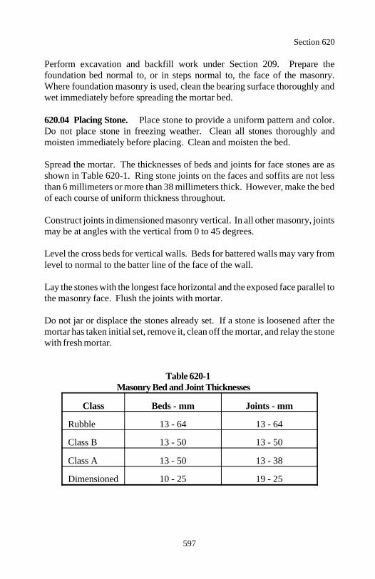
Section 620
597
Perform excavation and backfill work under Section 209. Prepare thefoundation bed normal to, or in steps normal to, the face of the masonry.Where foundation masonry is used, clean the bearing surface thoroughly andwet immediately before spreading the mortar bed.
620.04 Placing Stone. Place stone to provide a uniform pattern and color.Do not place stone in freezing weather. Clean all stones thoroughly andmoisten immediately before placing. Clean and moisten the bed.
Spread the mortar. The thicknesses of beds and joints for face stones are asshown in Table 620-1. Ring stone joints on the faces and soffits are not lessthan 6 millimeters or more than 38 millimeters thick. However, make the bedof each course of uniform thickness throughout.
Construct joints in dimensioned masonry vertical. In all other masonry, jointsmay be at angles with the vertical from 0 to 45 degrees.
Level the cross beds for vertical walls. Beds for battered walls may vary fromlevel to normal to the batter line of the face of the wall.
Lay the stones with the longest face horizontal and the exposed face parallel tothe masonry face. Flush the joints with mortar.
Do not jar or displace the stones already set. If a stone is loosened after themortar has taken initial set, remove it, clean off the mortar, and relay the stonewith fresh mortar.
Table 620-1Masonry Bed and Joint Thicknesses
Class Beds - mm Joints - mm
Rubble 13 - 64 13 - 64
Class B 13 - 50 13 - 50
Class A 13 - 50 13 - 38
Dimensioned 10 - 25 19 - 25
Section 620
598
620.05 Pointing. Point or finish all joints. Crown the mortar in the joints ontop surfaces slightly at the center of the masonry to provide drainage.
Where raked joints are required, squarely rake all mortar in exposed face jointsand beds to the required depth. Where weather joints are required, slightlyrake the joints. Do not leave the mortar flush with the stone faces.
Clean all face stone of mortar stains while the mortar is fresh. After the mortarsets, clean again using wire brushes and acid. Protect the masonry during hotor dry weather and keep it wet for at least 3 days after the work is completed.
620.06 Constructing Walls. Construct an L-shaped sample section of wallnot less than 1.5 meters high and 2.5 meters long, showing examples of facewall, top wall, method of turning corners, and method of forming joints. Donot construct masonry other than the foundation masonry before the sample isapproved.
Set face stones in random bond to produce the effect shown on the plans andto correspond with the approved sample section. Do not extend beds in anunbroken line through more than 5 stones and joints through more than 2stones. Bond each face stone with all contiguous face stones at least 150millimeters longitudinally and 50 millimeters vertically. Do not construct sothat the corners of four stones are adjacent to each other.
Do not bunch small stones or stones of the same size, color, or texture. Ingeneral, the stones decrease in size from the bottom to the top of work. Uselarge stones for the bottom courses and large, selected stones in the corners.
(a) Headers. Where required, distribute headers uniformly throughout thewalls of structures to form at least 20 percent of the faces.
(b) Backing. Construct the backing out of large stones. Bond the individualstones composing the backing and heart with the stones in the face wall andwith each other. Fill all openings and interstices in the backing completelywith mortar or with spalls surrounded completely by mortar.
Section 620
599
(c) Coping. Construct copings as shown on the plans. Where copings arenot called for, finish the top of the wall with stones wide enough to cover thetop of the wall from 0.5 to 1.5 meters in length, and of random heights, witha minimum height of 150 millimeters. Lay stones in a manner that the topcourse is an integral part of the wall. Pitch the tops of the top courses ofstone to line in both vertical and horizontal planes.
(d) Parapet walls. Use selected stones, squared and pitched to line and withheads dressed in the ends of parapet walls and in all exposed angles andcorners. Interlock headers with as many headers as possible extendingentirely through the wall. Interlock both the headers and stretchers in the 2faces of the wall. The headers and stretchers shall comprise practically thewhole volume of the wall. Completely fill all interstices and spalls withmortar.
(e) Weep holes. Provide weep holes for all walls and abutments. Placeweep holes at the lowest points where free outlets can be obtained and spacethem no more than 3 meters center to center.
620.07 Facing for Concrete.
(a) Stone placed before concrete. Make the back of the masonry unevento improve the bond to the concrete backing.
Use no. 10M reinforcing steel bent into an elongated letter S to anchor thestone. Embed each anchor in a mortar bed to within 50 millimeters from theface of the stones. Project the other end ±250 millimeters into the concretebacking. Space the anchors 0.5 meter apart both horizontally and vertically.
After the mortar has attained sufficient strength, clean the back masonrysurface of all dirt, loose material, and mortar drippings. Wash surfaces justbefore placing the concrete using a high-pressure water jet.
When placing the concrete, carry a neat cement grout of the consistency ofcream on top of the concrete and against the masonry at all times. Coat allinterstices in the back of the masonry with grout.
Section 620
600
(b) Concrete placed before stone. Allow a facing thickness as shown onthe plans. Set galvanized metal slots with anchors in the concrete face. Setthe anchors vertically at a horizontal spacing not exceeding 600 millimeters.Place a temporary filling of felt or other material in the slots to prevent fillingwith concrete.
Where setting the stone facing, fit the metal anchors tightly in the slots at anaverage vertical spacing of 600 millimeters. Bend at least 25 percent of theanchors at a short right angle to engage a recess cut in the stone. Extend theanchors to within 75 millimeters of the exposed face of the stone work.
Where the shape of the concrete face is unsuitable for the use of metal slots,use 3.8-millimeter galvanized iron wire ties at a rate of 7 ties for each squaremeter of exposed surface. Install ties after the concrete has cured using agun.
Keep the concrete face continuously wet for 2 hours preceding the placingof the stone and fill spaces between the stones and concrete with mortar.
620.08 Constructing Arches. Prepare and submit drawings for falseworkaccording to Section 562. Stratify arch ring stones parallel to the radial jointand stratify other stones parallel to the beds.
Lay out a full-size template of the arch ring near the quarry site showing facedimensions of each ring stone and thickness of joints. Receive approval beforethe shaping of any ring stone is started and place no ring stone in the structureuntil all ring stones have been shaped and dressed.
Construct arch centering according to the approved drawings. Provide suitablewedges for adjusting the elevation of the forms.
Set arch ring stones to the exact position and hold in place with hardwoodwedges until the joints are packed with mortar. When required, supportcentering with approved jacks to correct settlement after masonry placementbegins. Lower the centering gradually and symmetrically to avoid overstressesin the arch. Make the arch self-supporting before the railing or coping isplaced.
Section 620
601
For filled spandrel arches, strike the centers before constructing the spandrelwalls to avoid jamming of the expansion joints. Place the backfill so the ringis uniformly and symmetrically loaded.
620.09 Guardwall. Use cement rubble masonry. Concrete corewalls forguardwall may be cast-in-place or precast units according to Section 601,except the concrete shall have a minimum 28-day compressive strength of 25megapascals.
Construct an 8-meter sample section of guardwall. Do not construct additionalguardwall before the sample is approved.
Construct the guardwall true and uniform along its length with no stoneprojecting more than 38 millimeters beyond the neat line. Make mortar bedsand joints according to Table 620-1. Rake the joints and beds to a depth of 50millimeters on the front and top sides and to 38 millimeters on the back.
Use a one-piece capstone for the full width of the guardwall for at least 25percent of the total length. Use a two-piece capstone with the joint within 100millimeters of the guardwall center for the remaining length.
Place all stones, including the capstones, randomly to avoid a pattern. Laystones to reflect the width of the expansion joints. Do not leave a gap or amortar edge at the expansion joint. Use various size stones to coin or key thecorners of the guardwall.
620.10 Acceptance. Material for mortar will be evaluated under Subsec-tions 106.02 and 106.03. Mortar will be evaluated under Subsections 106.02and 106.04. See Table 620-2 for sampling and testing requirements.
Rock for masonry structures will be evaluated under Subsections 106.02 and106.04.
Construction or rehabilitation stone masonry structures will be evaluated underSubsections 106.02 and 106.04.
Excavation and backfill will be evaluated under Section 209.
Concrete will be evaluated under Section 601.
Section 620
602
Measurement
620.11 Measure stone masonry by the cubic meter in the structure. Do notmeasure sample wall sections not incorporated in the work.
Measure stone masonry guardwall by the meter along the front face of the wallincluding terminal sections.
Measure remove and reset stone masonry by the cubic meter in the structureafter resetting.
Measure repoint stone masonry by the meter of joint.
Payment
620.12 The accepted quantities, measured as provided above, will be paid atthe contract price per unit of measurement for the pay items listed below thatare shown in the bid schedule. Payment will be full compensation for all workprescribed in this Section. See Subsection 109.05.
Payment will be made under:
Pay Item Pay Unit
62001 (Class) masonry, ___ finish Cubic meter62002 Stone masonry guardwall Meter62003 Remove and reset stone masonry Cubic meter62004 Repoint stone masonry Meter
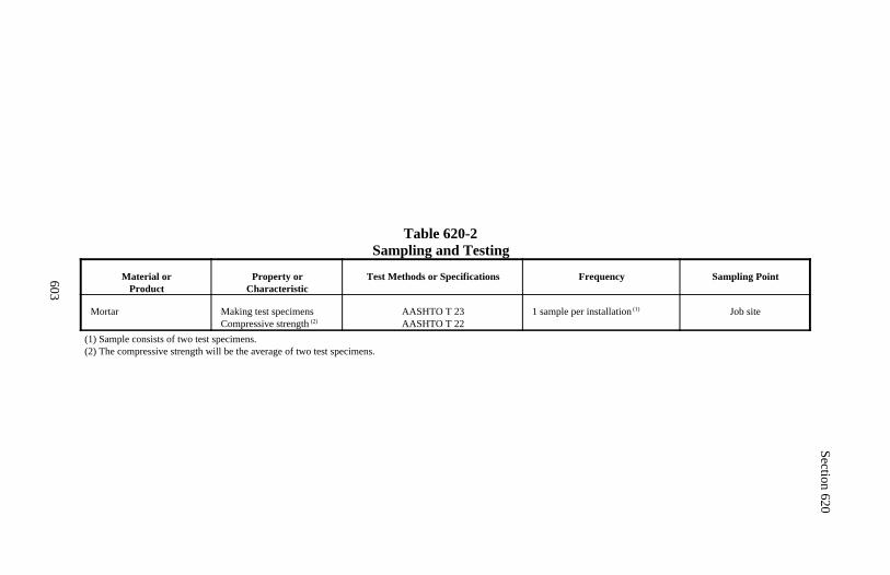
Section 620
603
Table 620-2Sampling and Testing
Material orProduct
Property orCharacteristic
Test Methods or Specifications Frequency Sampling Point
Mortar Making test specimensCompressive strength (2)
AASHTO T 23AASHTO T 22
1 sample per installation (1) Job site
(1) Sample consists of two test specimens.(2) The compressive strength will be the average of two test specimens.
604
Section 621.) MONUMENTS AND MARKERS
Description
621.01 This work consists of constructing right-of-way monuments, main-tenance markers, and similar monuments or posts.
Material
621.02 Conform to the following Sections and Subsections:
Concrete 601Paint 708Reflectors 718.12Reinforcing steel 709.01Treated structural timber and lumber 716.03Untreated structural timber and lumber 716.01
Construction Requirements
621.03 Monuments and Markers. Locate permanent points according toSection 152. Perform excavation and backfill work under Section 209. Seteach monument and marker vertically at the required location and elevation.Monuments may be cast-in-place or precast according to Section 601. Backfilland compact around the monument or marker to ensure that it is held firmly inplace.
621.04 Acceptance. Material (except concrete and paint) for monuments andmarkers will be evaluated under Subsections 106.02 and 106.03.
Construction of monuments and markers will be evaluated under Subsections106.02 and 106.04.
Location of permanent points will be evaluated under Section 152.
Structural excavation and backfill will be evaluated under Section 209.
Concrete will be evaluated under Section 601.
Paint will be evaluated under Section 563.
Section 621
605
Measurement
621.05 Measure monuments and markers by the each.
Payment
621.06 The accepted quantities, measured as provided above, will be paid atthe contract price per unit of measurement for the pay items listed below thatare shown in the bid schedule. Payment will be full compensation for the workprescribed in this Section. See Subsection 109.05.
Payment will be made under:
Pay Item Pay Unit
62101 Monument Each62102 Marker Each
606
Section 622.) RENTAL EQUIPMENT
Description
622.01 This work consists of furnishing and operating equipment for construc-tion work ordered by the CO and not otherwise provided for under the contract.
Construction Requirements
622.02 Rental Equipment. The CO will order in writing rental equipment foruse on the project. Submit the model number and serial number for each pieceof equipment before use. Make equipment available for inspection and ap-proval before use.
Furnish and operate equipment with such auxiliary attachments, oilers, etc., asare usually needed for efficient operation of the equipment. Keep the equip-ment in good repair and capable of operating 90 percent of the working time.
Obtain approval of the length of workday and workweek before beginningwork. Keep daily records of the number of unit-hours of operation. Submit therecords along with certified copies of the payroll.
622.03 Acceptance. Rental equipment work will be evaluated under Sub-section 106.02.
Measurement
622.04 Measure rental equipment by the hour of production time as orderedby the CO and furnished. Round portions of an hour up to the next half hour.Measure time in excess of 40 hours per week at the same rate as the first 40hours. Measure time for moving equipment between project work sites. Donot measure nonoperable equipment or equipment dependent upon anotherpiece of nonoperable equipment.

Section 622
607
Payment
622.05 The accepted quantities, measured as provided above, will be paid atthe contract price per unit of measurement for the pay item listed below that isshown in the bid schedule. Payment will be full compensation for the workprescribed in this Section. See Subsection 109.05.
Payment will be made under:
Pay Item Pay Unit
62201 (Type and size of equipment) Hour

608
Section 623.) GENERAL LABOR
Description
623.01 This work consists of furnishing workers and hand tools for construc-tion work ordered by the CO and not otherwise provided for under the contract.
Construction Requirements
623.02 Workers and Equipment. Furnish competent workers and appro-priate hand tools for the work.
Obtain approval of the length of workday and workweek before beginningwork. Keep daily records of the number of hours worked. Submit the recordsalong with certified copies of the payroll.
623.03 Acceptance. General labor work will be evaluated under Subsection106.02.
Measurement
623.04 Measure general labor by the hour as ordered by the CO and furnished.Round portions of an hour up to the next half hour. Measure time in excess of40 hours per week at the same rate as the first 40 hours. Do not measure timefor workers' transportation.
Payment
623.05 The accepted quantities, measured as provided above, will be paid atthe contract price per unit of measurement for the pay item listed below that isshown in the bid schedule. Payment will be full compensation for the workprescribed in this Section. See Subsection 109.05.
Payment will be made under:
Pay Item Pay Unit
62301 General labor Hour
609
Section 624.) TOPSOIL
Description
624.01 This work consists of furnishing and placing topsoil and placing con-served topsoil.
Material
624.02 Conform to the following Subsections:
Topsoil (furnished) 713.01(a)Topsoil (conserved) 713.01(b)
Construction Requirements
624.03 Preparing Areas. Shape all slopes and disturbed areas to be coveredwith topsoil. Disk or scarify slopes 1:3 or flatter to a depth of 100 millimeters.
624.04 Placing Topsoil. Provide at least 7 days notice before the start oftopsoil placement. Do not place topsoil when the ground or topsoil is frozen,excessively wet, or otherwise in a condition detrimental to the work. Use allconserved topsoil before furnishing topsoil. Keep the roadway surfaces cleanduring hauling and spreading operations.
Spread topsoil to a depth which, after settlement, will provide the requireddepth. Break clods and lumps with harrows, disks, or other appropriate equip-ment to provide a uniform textured soil. Remove and dispose of clods that willnot break down, stones larger than 50 millimeters, stumps, roots, and otherlitter according to Subsection 203.05.
Compact the topsoil after placement using a cleated roller, crawler tractor, orother similar equipment that will form longitudinal depressions at least 50millimeters deep perpendicular to the natural flow of water.
624.05 Acceptance. Material for topsoil (furnished) will be evaluated underSubsections 106.02 and 106.03.
Material for topsoil (conserved) will be evaluated under Subsection 106.02.
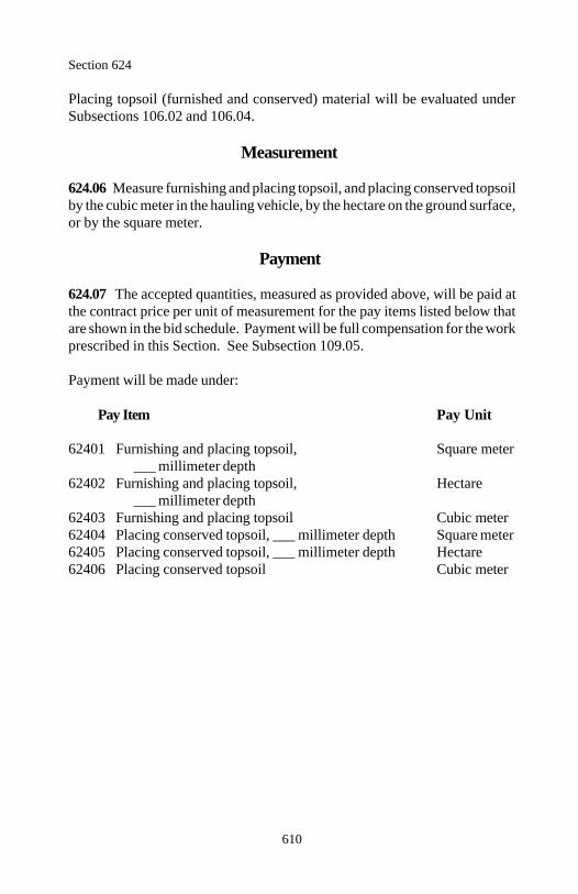
Section 624
610
Placing topsoil (furnished and conserved) material will be evaluated underSubsections 106.02 and 106.04.
Measurement
624.06 Measure furnishing and placing topsoil, and placing conserved topsoilby the cubic meter in the hauling vehicle, by the hectare on the ground surface,or by the square meter.
Payment
624.07 The accepted quantities, measured as provided above, will be paid atthe contract price per unit of measurement for the pay items listed below thatare shown in the bid schedule. Payment will be full compensation for the workprescribed in this Section. See Subsection 109.05.
Payment will be made under:
Pay Item Pay Unit
62401 Furnishing and placing topsoil, Square meter___ millimeter depth
62402 Furnishing and placing topsoil, Hectare___ millimeter depth
62403 Furnishing and placing topsoil Cubic meter62404 Placing conserved topsoil, ___ millimeter depth Square meter62405 Placing conserved topsoil, ___ millimeter depth Hectare62406 Placing conserved topsoil Cubic meter
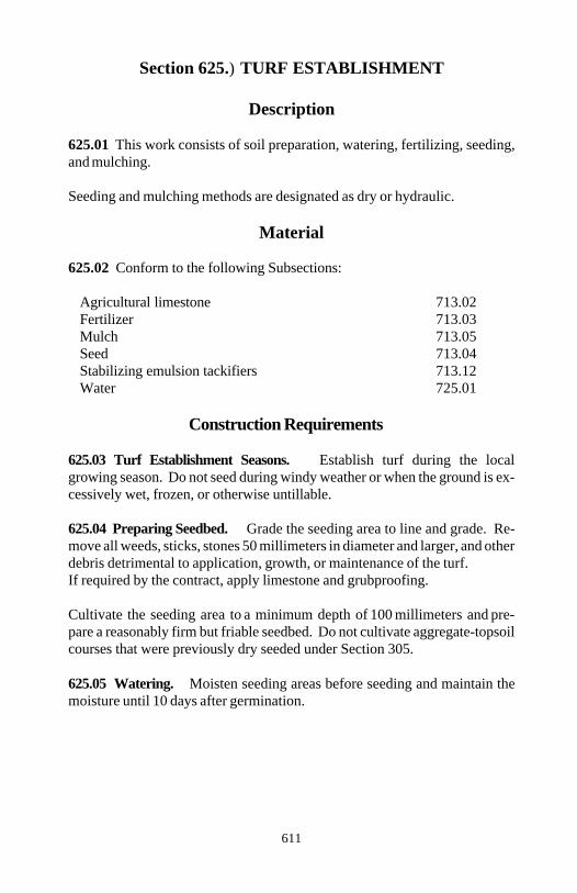
611
Section 625.) TURF ESTABLISHMENT
Description
625.01 This work consists of soil preparation, watering, fertilizing, seeding,and mulching.
Seeding and mulching methods are designated as dry or hydraulic.
Material
625.02 Conform to the following Subsections:
Agricultural limestone 713.02Fertilizer 713.03Mulch 713.05Seed 713.04Stabilizing emulsion tackifiers 713.12Water 725.01
Construction Requirements
625.03 Turf Establishment Seasons. Establish turf during the localgrowing season. Do not seed during windy weather or when the ground is ex-cessively wet, frozen, or otherwise untillable.
625.04 Preparing Seedbed. Grade the seeding area to line and grade. Re-move all weeds, sticks, stones 50 millimeters in diameter and larger, and otherdebris detrimental to application, growth, or maintenance of the turf. If required by the contract, apply limestone and grubproofing.
Cultivate the seeding area to a minimum depth of 100 millimeters and pre-pare a reasonably firm but friable seedbed. Do not cultivate aggregate-topsoilcourses that were previously dry seeded under Section 305.
625.05 Watering. Moisten seeding areas before seeding and maintain themoisture until 10 days after germination.
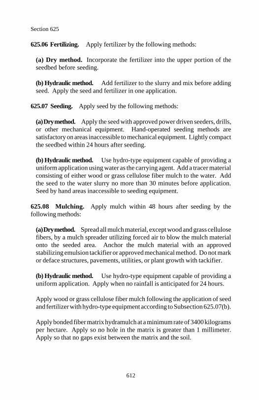
Section 625
612
625.06 Fertilizing. Apply fertilizer by the following methods:
(a) Dry method. Incorporate the fertilizer into the upper portion of theseedbed before seeding.
(b) Hydraulic method. Add fertilizer to the slurry and mix before addingseed. Apply the seed and fertilizer in one application.
625.07 Seeding. Apply seed by the following methods:
(a) Dry method. Apply the seed with approved power driven seeders, drills,or other mechanical equipment. Hand-operated seeding methods aresatisfactory on areas inaccessible to mechanical equipment. Lightly compactthe seedbed within 24 hours after seeding.
(b) Hydraulic method. Use hydro-type equipment capable of providing auniform application using water as the carrying agent. Add a tracer materialconsisting of either wood or grass cellulose fiber mulch to the water. Addthe seed to the water slurry no more than 30 minutes before application.Seed by hand areas inaccessible to seeding equipment.
625.08 Mulching. Apply mulch within 48 hours after seeding by thefollowing methods:
(a) Dry method. Spread all mulch material, except wood and grass cellulosefibers, by a mulch spreader utilizing forced air to blow the mulch materialonto the seeded area. Anchor the mulch material with an approvedstabilizing emulsion tackifier or approved mechanical method. Do not markor deface structures, pavements, utilities, or plant growth with tackifier.
(b) Hydraulic method. Use hydro-type equipment capable of providing auniform application. Apply when no rainfall is anticipated for 24 hours.
Apply wood or grass cellulose fiber mulch following the application of seedand fertilizer with hydro-type equipment according to Subsection 625.07(b).
Apply bonded fiber matrix hydramulch at a minimum rate of 3400 kilogramsper hectare. Apply so no hole in the matrix is greater than 1 millimeter.Apply so that no gaps exist between the matrix and the soil.
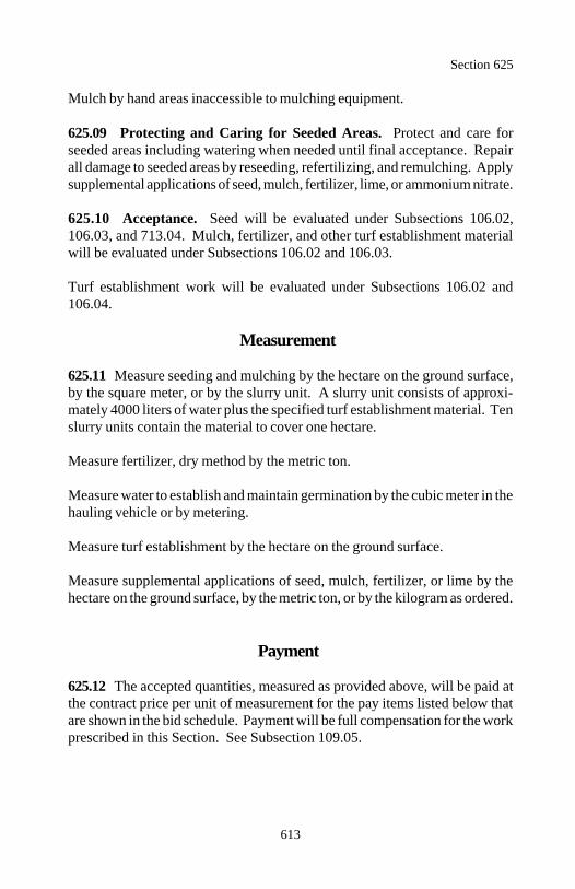
Section 625
613
Mulch by hand areas inaccessible to mulching equipment.
625.09 Protecting and Caring for Seeded Areas. Protect and care forseeded areas including watering when needed until final acceptance. Repairall damage to seeded areas by reseeding, refertilizing, and remulching. Applysupplemental applications of seed, mulch, fertilizer, lime, or ammonium nitrate.
625.10 Acceptance. Seed will be evaluated under Subsections 106.02,106.03, and 713.04. Mulch, fertilizer, and other turf establishment materialwill be evaluated under Subsections 106.02 and 106.03.
Turf establishment work will be evaluated under Subsections 106.02 and106.04.
Measurement
625.11 Measure seeding and mulching by the hectare on the ground surface,by the square meter, or by the slurry unit. A slurry unit consists of approxi-mately 4000 liters of water plus the specified turf establishment material. Tenslurry units contain the material to cover one hectare.
Measure fertilizer, dry method by the metric ton.
Measure water to establish and maintain germination by the cubic meter in thehauling vehicle or by metering.
Measure turf establishment by the hectare on the ground surface.
Measure supplemental applications of seed, mulch, fertilizer, or lime by thehectare on the ground surface, by the metric ton, or by the kilogram as ordered.
Payment
625.12 The accepted quantities, measured as provided above, will be paid atthe contract price per unit of measurement for the pay items listed below thatare shown in the bid schedule. Payment will be full compensation for the workprescribed in this Section. See Subsection 109.05.
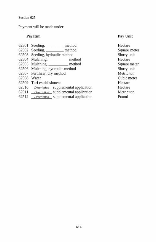
Section 625
614
Payment will be made under:
Pay Item Pay Unit
62501 Seeding, _________ method Hectare62502 Seeding, _________ method Square meter62503 Seeding, hydraulic method Slurry unit62504 Mulching, __________ method Hectare62505 Mulching, __________ method Square meter62506 Mulching, hydraulic method Slurry unit62507 Fertilizer, dry method Metric ton62508 Water Cubic meter62509 Turf establishment Hectare62510 Description supplemental application Hectare62511 Description supplemental application Metric ton62512 Description supplemental application Pound
615
Section 626.) PLANTS, TREES, SHRUBS, VINES,AND GROUNDCOVERS
Description
626.01 This work consists of furnishing and planting trees, shrubs, vines,groundcovers, and other plants.
Material
626.02 Conform to the following Subsections:
Fertilizer 713.03Miscellaneous planting material 713.08Mulch 713.05Plant material 713.06Topsoil 713.01Water 725.01
Construction Requirements
626.03 General. Do not plant in frozen ground, when snow covers theground, or when the soil is in an unsatisfactory condition for planting.
Furnish stock with a fibrous, cohesive root system. Do not provide container-grown stock that is pot-bound, that has a top system out of proportion (larger)to the size of the container, or that has roots growing out of the container.
626.04 Inspecting and Delivering. Notify the CO 30 days in advance of thedelivery of material to permit the CO the opportunity to select material at thesource. Submit commercial certifications and complete written informationconcerning the source of supply for all plant material at least 15 days beforedelivery of plants to the project.
626.05 Protection and Temporary Storage. Keep all plant material moistand protected (covered) in transit, in temporary storage, and on the projectawaiting planting. Protect plants delivered but not scheduled for immediateplanting as follows:
Section 626
616
(a) Open the bundles of bare root material, separate plants, and cover theroots in moist trenches.
(b) Cover the earth balls of balled and burlapped material with mulch orother suitable material and keep moist.
Install all plant material received on site within 30 days.
626.06 Excavation for Plant Pits and Beds. Remove all sod, weeds, roots,and other unsuitable material from the planting site. Excavate plant pits asfollows:
(a) Width of excavation.
(1) For root spread or ball diameters up to 1 meter, dig the pits circular inoutline to the root spread plus 0.5 meter.
(2) For root spreads or ball diameters over 1 meter, excavate 1.5 times theroot spread.
(b) Depth of excavation. Dig the pits to a depth that permits a minimum of150 millimeters of backfill under the roots or balls or dig the pits to thefollowing depths, whichever is deeper:
(1) Deciduous trees.
(a) Under 38 millimeters caliper. 0.5 meter deep(b) Over 38 millimeters caliper. 1 meter deep
(2) Deciduous and evergreen shrubs.
(a) Under 0.5 meter height. 0.3 meters deep(b) Over 0.5 meter height. 0.5 meters deep
(3) Evergreen trees.
(a) Under 1.5 meters height. 0.2 meters plus ball height (b) Over 1.5 meters height. 0.3 meters plus ball height
(4) Vines and groundcovers. Double the size of the pot.
Section 626
617
Loosen soil at the sidewalls and bottom of the plant pit to a depth of 150millimeters before setting the plant.
626.07 Setting Plants. Do not plant material until inspected and approved bythe CO. Plants not meeting specifications, arriving on site in an unsatisfactorycondition, or showing sign of improper handling will be rejected. Immediatelyremove and dispose of all rejected plants off site and replace with approvednursery stock.
Prepare a backfill mixture of 4 parts topsoil, loam, or selected soil to one partpeat moss. Place backfill mixture in the bottom of the plant pit. Set all plantsapproximately plumb and at the same level or slightly lower than the depth atwhich they were grown in the nursery or collected in the field. Set plants asfollows:
(a) Bare root stock. Place bare rooted plants in the center of the plant pitwith the roots properly spread in a natural position. Cut broken or damagedroots back to sound root growth. Work backfill mixture around and over theroots and tamp.
(b) Balled and burlapped stock. Handle and move plants by the ball.Place balled and burlapped plants in the prepared pits on tamped backfillmixture. Backfill around the plant ball to half the depth of the ball. Tampand thoroughly water. Cut the burlap and remove it from the upper half ofthe ball or loosen the burlap and fold it back. If wire baskets are used cut thewire from the upper half of the basket. Backfill the remainder of the plantwith backfill mixture.
(c) Container-grown stock. Remove the container just before planting.Place plants in the prepared pits on tamped backfill mixture. Backfill theremainder of the plant with backfill mixture and tamp.
626.08 Fertilizing. Fertilize using either of the following methods:
(a) Mix the fertilizer with the backfill mixture when it is prepared.
(b) Spread the fertilizer uniformly around the pit area of individual plants orover shrub beds. Cultivate the fertilizer into the top 50 millimeters of thebackfill mixture.
Section 626
618
626.09 Watering. Construct 100-millimeter deep water basins around treesand 75-millimeter deep water basins around shrubs. Make the diameter of thebasin equal to that of the plant pit.
Water plants during and immediately after planting and throughout the plantestablishment period. Saturate the soil around each plant at each watering.
626.10 Guying and Staking. When guying and staking is specified, guydeciduous trees just below the first lateral branch and guy evergreen trees halfway up the height of the tree. Do not leave the guys and stakes on a tree formore than one growing season.
626.11 Pruning. Prune before or immediately after planting to preserve thenatural character of each plant. Use experienced personnel to perform thepruning. Use accepted horticultural practice. Paint cuts over 20 millimetersin diameter with tree wound dressing.
626.12 Mulching. Place mulch within 24 hours after planting. Place mulchmaterial over all pit or water basin areas of individual trees and shrubs and overthe entire shrub bed. If wood fiber is used, apply nitrogen at the rate of 5kilograms per cubic meter to the mulch material.
626.13 Plant Establishment Period. The plant establishment period is a one-year period beginning at the completion of the project. Employ all necessarymeans to preserve the plants in a healthy growing condition during the plantestablishment period. Care during the establishment period includes watering,cultivating, pruning, repairing, adjusting guys and stakes, and controllinginsects and disease.
626.14 Acceptance. Plant material (including plants, fertilizer, mulch, andtopsoil) will be evaluated under Subsections 106.02 and 106.03.
Planting of trees, shrubs, vines, groundcovers and other plants will beevaluated under Subsections 106.02 and 106.04 and as follows:
An inspection of the plant material will be made about 15 days before the endof the plant establishment period to identify all dead, dying, or diseased plantsfor removal and replacement. During the following planting season, removeand replace all identified plants according to this Section. A final inspectionof all plant material within 15 days after completion of all replacement plantingwill be the basis for final acceptance.
Section 626
619
Measurement
626.15 Measure plants by the each.
Payment
626.16 The accepted quantities, measured as provided above, will be paid atthe contract price per unit of measurement for the pay item listed below that isshown in the bid schedule. Payment will be full compensation for the workprescribed in this Section. See Subsection 109.05.
Partial payments for plants will be made as follows:
(a) 75 percent of the bid price will be paid following initial planting.
(b) The remaining 25 percent of the bid price will be paid after the final in-spection.
Payment will be made under:
Pay Item Pay Unit
62601 (Plant name) , (size) Each
620
Section 627.) SOD
Description
627.01 This work consists of furnishing and placing living sod of perennialturf-forming grasses.
Sod placement is designated as solid, strip, or spot according to Subsection627.06.
Material
627.02 Conform to the following Subsections:
Agricultural limestone 713.02Fertilizer 713.03Pegs for sod 713.11Sod 713.10Water 725.01
Construction Requirements
627.03 General. Move and lay sod during dry weather and on dry, unfrozenground.
627.04 Inspecting and Delivering. Provide at least 3 days notice beforecutting sod. The CO will approve the sod in its original position before cutting.Do not deliver sod until the soil is prepared.
627.05 Preparing the Soil. Clear and grade the area to be sodded. Cultivate,disk, harrow, or otherwise loosen the grade to a depth of not less than 100millimeters. Remove stones larger than 50 millimeters in any diameter, sticks,stumps, and other debris that might interfere with the proper placement orsubsequent growth.
Topsoil according to Section 624.
Apply fertilizer and agricultural limestone uniformly over the sodding area.Mechanical spreaders or blower equipment may be used. Disk or till thefertilizer and limestone into the soil to a depth of 100 millimeters.
Moisten the prepared soil.
Section 627
621
627.06 Placing Sod. Place sod within 24 hours after cutting or within 5 daysafter cutting when the sod is stored in moist stacks, grass-to-grass and roots-to-roots. Protect sod against drying and from freezing.
(a) Solid sod. Place sod perpendicular to drainage flows. Place sections ofsolid sod edge to edge with staggered joints. Plug openings with sod or fillopenings with acceptable loamy seeded topsoil. Roll or tamp sod toeliminate air pockets and provide an even surface. On slopes 1:2 or steeperand in channels, peg sod on 0.5 meter centers after rolling or tamping. Drivepegs flush with the sod bed surface.
(b) Strip sod. Lay strip sod in shallow trenches in parallel rows. Firmly rollor tamp until the surface of the sod is level with or below the adjacent soil.Seed the soil between the strips of sod according to Section 625. Rake ordrag the seeded areas to cover the seed.
(c) Spot sod. Place sod blocks. Roll or tamp the blocks into the soil untilthe sod surfaces are slightly below the surrounding ground surface.
Blend final grades with existing adjacent areas. Leave the entire area drainableand free from abrupt changes in slope.
627.07 Maintaining Sodded Areas. Water sod when placing and keep moist.Avoid erosion when watering.
Erect warning signs and barriers to protect newly sodded areas. Do not allowwheeled vehicles on newly sodded areas.
Mow sodded areas and repair or replace sodded areas that are damaged or failto show a uniform growth of grass. Maintain sodded areas and replace allnonliving sod until final acceptance of the project.
627.08 Acceptance. Material (including lime and fertilizer) for sodding willbe evaluated under Subsections 106.02 and 106.03.
Sod placement will be evaluated under Subsections 106.02 and 106.04.
Topsoil will be evaluated under Section 624.
Section 627
622
Measurement
627.09 Measure sod by the square meter. Do not measure nonsodded areasadjacent to strip and spot sodding.
Measure topsoil under Section 624.
Measure water and seeding under Section 625.
Payment
627.10 The accepted quantities, measured as provided above, will be paid atthe contract price per unit of measurement for the pay item listed below that isshown in the bid schedule. Payment will be full compensation for the workprescribed in this Section. See Subsection 109.05.
Payment will be made under:
Pay Item Pay Unit
62701 ___________ sod Square meter
623
Section 628.) SPRIGGING
Description
628.01 This work consists of furnishing and planting living grass plants. Sprigging is designated as broadcast, row, or spot according to Subsection628.06.
Material
628.02 Conform to the following Subsections:
Agricultural limestone 713.02Fertilizer 713.03Mulch 713.05Sprigs 713.09Water 725.01
Construction Requirements
628.03 General. Do not sprig during windy weather or when the ground isdry, excessively wet, frozen, or otherwise untillable.
628.04 Harvesting Sprigs. Provide at least 5 days notice before harvestingsprigs. Before harvesting, mow grass and weeds to a height of 65±15millimeters and remove all clippings.
Loosen sprigs by cross-disking, shallow plowing, or other acceptable methods.Gather the sprigs in small piles or windrows, water, and keep moist untilplanting. Dispose of sprigs that freeze or dry out.
628.05 Preparing the Soil. Prepare the soil according to Subsection 627.05.
628.06 Planting Sprigs. Plant the sprigs within 24 hours after harvesting. (a) Broadcast sprigging. Broadcast sprigs by hand or suitable equipmentin a uniform layer over the prepared surface with spacing between sprigs notto exceed 150 millimeters. Force the sprigs into the soil to a depth of 75±25millimeters with a straight spade, a disk harrow, or other equipment.
(b) Row sprigging. Open furrows along the approximate contour of slopes.Place sprigs in a continuous row in the open furrow with successive sprigstouching. Cover the sprigs immediately.
Section 628
624
(c) Spot sprigging. Spot sprig according to (b) above, except that insteadof planting in a continuous row, group 4 or more sprigs 0.5 meter apart inthe rows.
After planting, clear the surface of stones larger than 25 millimeters, largeclods, roots, and other litter brought to the surface during sprigging. Lightlycompact sprigged area within 24 hours. Do not compact when soil is so wetthat it is picked up by the equipment. Do not compact clayey soils.
When mulch is required by the contract, cover the sprigged area with mulchwithin 24 hours according to Section 625.
628.07 Maintaining Sprigged Areas. Keep the sprigged areas moist. Watercarefully to avoid erosion.
Erect warning signs and barriers to protect newly sprigged areas. Regrade andresprig all areas damaged.
628.08 Acceptance. Material (including lime and fertilizer) for spigging willbe evaluated under Subsections 106.02 and 106.03.
Planting living grass plants will be evaluated under Subsections 106.02.
Preparing of soil will be evaluated under Section 627.
Mulch will be evaluated under Section 625.
Measurement
628.09 Measure sprigging by the hectare on the ground surface or by thesquare meter.
Measure topsoil under Section 624.
Measure water under Section 625.

Section 628
625
Payment
628.10 The accepted quantities, measured as provided above, will be paid atthe contract price per unit of measurement for the pay items listed below thatare shown in the bid schedule. Payment will be full compensation for the workprescribed in this Section. See Subsection 109.05.
Payment will be made under:
Pay Item Pay Unit
62801 ___________ sprigging Hectare62802 ___________ sprigging Square meter
626
Section 629.) EROSION CONTROL MATS, ROVING, AND CELLULAR CONFINEMENT SYSTEMS
Description
629.01 This work consists of constructing erosion control for ditch and slopeprotection, and stabilization. This includes installing mats, roving, and cellularconfinement systems.
Erosion control mats are designated as follows:
Type 1 Straw mats, burlap fabric, jute mesh, and woven paper or sisal meshnetting
Type 2 Straw and coconut mats, excelsior blanket, or mulch blanketType 3 Coconut matType 4 Synthetic erosion control mats and meshesType 5 Turf reinforcement mats
Material
629.02 Conform to the following Sections and Subsections:
Erosion control mats 713.07(a)Emulsified asphalt 702.03Cellular confinement systems 713.07(c)Roving 713.07(b)Topsoil 624Turf establishment 625
Construction Requirements
629.03 Erosion Control Mats (Types 1, 2, 3, 4, and 5). Install erosioncontrol mats according to the manufacturer's recommendations.
Install erosion control mats to soil surfaces which are at final grade, stable,firm, and free of rocks or other obstructions. Spread erosion control matsevenly and smoothly, without stretching, to ensure direct contact with the soilat all points. Unroll erosion control mats parallel to the drainage flow direc-tion. Lap edges as recommended by the manufacturer. Place the upslope endin a 150-millimeter vertical slot. Backfill the slot and compact.
Section 629
627
For swale or ditch installations, place up the side slopes to extend above antici-pated flow line and construct intermediated 150-millimeter vertical check slotsat 8-meter intervals. Construct check slots perpendicular to flow direction.Staple erosion control mats as recommended by manufacturer. Drive allstaples flush with the soil surface.
Repair damaged areas immediately. Restore the soil in damaged areas tofinished grade, refertilize, and reseed.
(a) Synthetic erosion control mats and meshes (type 4). Install after Sec-tion 625 (Turf Establishment) is in place.
(b) Turf reinforcement mats (type 5). Install before Section 625 (TurfEstablishment) is in place. After seeding, lightly brush or rake 15±5millimeter of topsoil into the mat voids to fill the mat thickness.
629.04 Roving. Furnish a pneumatic ejector capable of applying roving at arate of 0.9 kilograms per minute. Furnish an air compressor capable of supply-ing 1.1 cubic meters per minute at 620±70 kilopascals, complete with air hosesnecessary for supplying air to areas not accessible to the compressor. Furnishan asphalt distributor with necessary hoses and a hand spray bar for slopes andother areas not accessible to the distributor.
(a) Fiber glass roving. Spread fiber glass roving uniformly at the rate of0.16±0.03 kilograms per square meter to form a random mat of continuousglass fibers.
(b) Polypropylene roving. Spread polypropylene roving uniformly at therate of 0.08±0.03 kilograms per square meter to form a random mat ofcontinuous polypropylene fibers.
Anchor the roving to the ground with a slow setting emulsified asphalt applieduniformly at a rate of 1.5±0.2 liters per square meter over the roving. Buryupslope end of the roving 300 millimeters deep.
629.05 Cellular Confinement System. Excavate to the depth of the cellularconfinement system, and smooth and compact the slope. Install the top of thesystem flush or lower than the adjacent slope. Expand the geocell down theslope. Connect adjacent geocell sections with hog rings or staples every othercell.
628
Anchor the system with stakes across the top at every other cell. Repeat theanchoring pattern in every tenth row and in the bottom row.
Backfill the system with topsoil. Hand-compact the topsoil within each cell.Apply permanent turf establishment according to Section 625.
629.05 Acceptance. Material (including mats, roving, and cellular con-finement systems) for erosion control, ditch and slope protection, and stabi-lization will be evaluated under Subsections 106.02 and 106.03.
Installation of erosion control mats, roving, and cellular confinement systemswill be evaluated under Subsections 106.02 and 106.04.
Topsoil will be evaluated under Section 624.
Turf establishment will be evaluated under Section 625.
Measurement
629.07 Measure erosion control mats, roving, and cellular confinement sys-tems by the square meter excluding overlaps.
Measure topsoil under Section 624.
Measure turf establishment under Section 625.
Payment
629.08 The accepted quantities, measured as provided above, will be paid atthe contract price per unit of measurement for the pay items listed below thatare shown in the bid schedule. Payment will be full compensation for the workprescribed in this Section. See Subsection 109.05.
Payment will be made under:
Pay Item Pay Unit
62901 Erosion control mat type ____ Square meter62902 Roving Square meter62903 Cellular confinement system Square meter

Section 629
629
Sections 630, 631, and 632 Reserved
630
Section 633. ) PERMANENT TRAFFIC CONTROL
Description
633.01 This work consists of constructing permanent traffic control signs,supports, delineators, and object markers, and removing and resetting per-manent traffic control devices.
Sign panels are designated as plywood, aluminum, steel, plastic, or fiberglassreinforced plastic.
Sign retroreflective sheeting type is designated according to Subsection 718.01.
Posts are designated as wood, aluminum, or steel.
Material
633.02 Conform to the MUTCD and the following Section and Subsec-tions:
Aluminum panels 718.05Concrete 601Delineator and object marker retroreflectors 718.12Extruded aluminum panels 718.07Fiberglass reinforced plastic panels 718.06(b)Hardware 718.10Insulating material 556.06(e)Letters, numerals, arrows, symbols, and borders 718.11Object marker and delineator posts 718.09Plastic panels 718.06(a)Plywood panels 718.03Retroreflective sheeting 718.01Signposts 718.08Steel panels 718.04
Construction Requirements
633.03 General. Furnish traffic control devices according to the MUTCD andStandard Highway Signs published by FHWA. Submit the sign list forapproval before ordering.
Section 633
631
633.04 Supports. Sign locations shown on the plans may be changed to fitfield conditions. Determine the lengths of posts at time of staking.
Drive posts with a suitable driving head or set posts in drilled or punchedholes. Replace all posts damaged by driving. Erect sign supports plumb,backfill, and compact.
Construct concrete footings according to Section 601. Perform excavation andbackfill work under Section 209.
633.05 Panels. Use type I, II, III, or IV retroreflective sheeting. Use type L-1letters, numerals, arrows, symbols, and borders. Cut panels to size and shapeand drill or punch all holes. Make panels flat and free of buckles, warp, dents,cockles, burrs, and other defects.
Clean and degrease the face of metal panels using methods recommended bythe retroreflective sheeting manufacturer. Abrade, clean, and degrease the faceof the plywood panels using methods recommended by the retroreflectivesheeting manufacturer. Treat the edges of the plywood panel with an approvededge sealant. Apply the retroreflective sheeting material to the panels.Package sign panels in protective material and transport them in a verticalposition.
Mount sign panels with the legend horizontal. Where multiple panels adjoin,limit the gap between adjacent panels to 2 millimeters. To reduce specularglare (mirror reflection), turn the sign panel 3 degrees away from the road inthe direction of travel.
Place insulating material to prevent contact between aluminum and steelmaterial. Use oversized bolt heads and neoprene or nylon washers for fas-tening plastic sign panels.
Do not field drill holes in any part of the panel. Use antitheft fasteners wherepossible. Paint all bolt heads, screw heads, and washers that are exposed onthe sign face. Match the color of the paint to the color of the background ormessage area at the point where the fitting is exposed.
If a sign message is not applicable, completely cover the face of the sign withan opaque material. Maintain the covering in good condition until the messagebecomes applicable. Do not use adhesive tape on the sign face.
Section 633
632
Repair or replace damaged parts including sheeting.
633.06 Delineators and Object Markers. Attach delineators and objectmarkers to posts according to the manufacturer's recommendation.
633.07 Removing and Resetting Permanent Traffic Control Devices.Remove and store the existing signs, delineators, and object markers. Replaceall devices, posts, and hardware damaged during removal, storage, and raising.
633.08 Acceptance. Material (including signs panels, retroreflective sheeting,supports, delineators, object markers, and hardware) for traffic control deviceswill be evaluated under Subsections 106.02 and 106.03.
Installation of traffic control devices will be evaluated under Subsections106.02 and 106.04.
Excavation and backfill will be evaluated under Section 209.
Concrete will be evaluated under Section 601.
Measurement
633.09 Measure sign installations by the each or by the square meter of frontface sign panel as follows:
(a) When an installation is measured by the each, measure each installationas one sign regardless of the number of sign panels or posts in theinstallation.
(b) When an installation is measured by the square meter, measure thenominal dimensions of all the sign panels in the installation.
(c) A sign installation includes the support.
Measure signs by the each or by the square meter of front face sign panel.Measure each sign in a multiple configuration.
Measure posts by the meter.
Section 633
633
Measure object markers and delineators by the each.
Measure removing and resetting permanent traffic control devices by the eachafter they are reset. Measure based on the number of devices reset in their finalposition as described in (a) above.
Payment
633.10 The accepted quantities, measured as provided above, will be paid atthe contract price per unit of measurement for the pay items listed below thatare shown in the bid schedule. Payment will be full compensation for the workprescribed in this Section. See Subsection 109.05.
Payment will be made under:
Pay Item Pay Unit
63301 Sign installation Each63302 Sign installation Square meter63303 Signs, ________ panels, type ___ sheeting Each63304 Signs, ________ panels, type ___ sheeting Square meter63305 Posts, ________ Meter63306 Object markers (description) Each63307 Delineators (description) Each63308 Removing and resetting (description) Each
634
Section 634.) PERMANENT PAVEMENT MARKINGS
Description
634.01 This work consists of applying permanent pavement markings andraised pavement markers on the completed pavement.
Pavement markings are designated as follows:
Type A Conventional traffic paint with type 1 glass beadsType B Waterborne traffic paint with type 1 glass beadsType C Waterborne traffic paint with type 3 glass beadsType D Epoxy markings with type 1 glass beadsType E Epoxy markings with type 1 and type 4 glass beadsType F Polyester markings with type 1 glass beadsType G Polyester markings with type 1 and type 4 glass beadsType H Thermoplastic markings with type 1 glass beadsType I Thermoplastic markings with type 1 and type 5 glass beadsType J Preformed plastic markingsType K Nonreflectorized markings
Material
634.02 Conform to the MUTCD and the following Subsections:
Conventional traffic paint 718.13Epoxy markings 718.15Epoxy resin adhesives 718.23Glass beads 718.19Polyester markings 718.16Preformed plastic markings 718.18Raised pavement markers 718.20Thermoplastic markings 718.17Waterborne traffic paint 718.14
Section 634
635
Construction Requirements
634.03 General. Where existing and final pavement marking locations areidentical, stake the limits of all existing pavement markings (no-passing zones,edge stripes, etc.) before any pavement work. Upon completion of the finalsurface course, establish line limits for the new pavement for approval beforemarking. Establish markings according to the MUTCD.
Remove loose particles, dirt, tar, grease, and other deleterious material fromthe surface to be marked. Where markings are placed on portland cementconcrete pavement less than 1 year old, clean the pavement of all residue andcuring compounds. Remove temporary pavement markings the same daypermanent pavement markings are applied. Apply markings to a clean, drysurface according to the MUTCD.
At least 7 days before applying pavement markings, furnish a written copy ofthe marking manufacturer's recommendations for use. A field demonstrationmay be required to verify the adequacy of recommendations.
Ship marking material in appropriate containers plainly marked with thefollowing information as appropriate for the material being furnished:
(a) Manufacturer's name and address(b) Name of product(c) Lot/batch numbers(d) Color(e) Net mass and volume of contents(f) Date of manufacture(g) Date of expiration(h) Statement of contents (if mixing of components is required)(i) Mixing proportions and instructions(j) Safety information
Apply pavement markings in the direction of traffic according to the manu-facturer's recommendations. Apply all markings to provide a clean-cut,uniform, and workmanlike appearance by day and night.
Section 634
636
Make lines 100 millimeters wide. Make broken lines 3 meters long with 9-meter gaps. Make dotted lines 0.5 meter long with 1-meter gaps. Separatedouble lines with a 100-millimeter space.
Protect marked areas from traffic until the markings are dried to no-trackingcondition. Remove all tracking marks, spilled marking material, markings inunauthorized areas, and defective markings.
634.04 Conventional Traffic Paint (Type A). Apply paint when thepavement and air temperatures are above 4 C. Spray paint at 0.38 millimetersminimum wet film thickness before glass beads or at a rate of 2.6 square metersper liter. Immediately apply type 1 glass beads on the paint at a minimum rateof 0.7 kilograms per liter of paint.
On new asphalt pavements or new asphalt surface treatments, apply two coats.Apply the first coat at 8.8 square meters per liter and the second coat at 3.7square meters per liter.
634.05 Waterborne Traffic Paint (Type B and C). Apply paint when thepavement and air temperatures are above 10 C. Spray paint at 0.38 milli-meters minimum wet film thickness before glass beads or at a of rate 2.6 squaremeters per liter.
Type B. Immediately apply type 1 glass beads on the paint at a minimumrate of 0.7 kilograms per liter of paint.
Type C. Immediately apply type 3 glass beads on the paint at a minimumrate of 1.4 kilograms per liter of paint.
On new asphalt pavements or new asphalt surface treatments, apply two coats.Apply each coat at 5.2 square meters per liter.
634.06 Epoxy Markings (Types D and E). Heat components A and Bseparately at 43±17 C and mix. Discard all material heated over 60 C. Ap-ply epoxy when the pavement and air temperatures are above 10 C. Apply asa spray at 43±17 C (gun tip temperature) at a 0.38 millimeters minimum dryfilm thickness or 2.6 square meters per liter.
Type D. Immediately apply type 1 glass beads on the epoxy at a minimumrate of 1.8 kilograms per liter of epoxy.
Section 634
637
Type E. Use two bead dispensers. Immediately apply type 4 glass beads onthe epoxy at a minimum rate of 1.4 kilograms per liter of epoxy immediatelyfollowed by an application of type 1 glass beads at a minimum rate of 1.4kilograms per liter.
634.07 Polyester Markings (Types F and G). Apply polyester when thepavement and air temperatures are above 10 C. Spray at 53±4 C (gun tiptemperature) at a 0.38 millimeters minimum dry film thickness or 2.6 squaremeters per liter. Discard all material heated over 66 C. Do not use fast drypolyester markings on hot asphalt concrete pavements less than 1 year old.
Type F. Immediately apply type 1 glass beads on the polyester at a mini-mum rate of 1.8 kilograms per liter of polyester.
Type G. Use two bead dispensers. Immediately apply type 4 glass beads onthe polyester at a minimum rate of 1.4 kilograms per liter of polyester imme-diately followed by an application of type 1 glass beads at a minimum rateof 1.4 kilograms per liter.
634.08 Thermoplastic Markings (Type H and I). On areas to be marked onportland cement concrete pavements and old asphalt pavements, apply anepoxy resin primer/sealer according to the thermoplastic manufacturer'srecommendations. Allow the primer/sealer to dry.
Apply thermoplastic when the pavement and air temperatures are above 10 C.Spray or extrude the thermoplastic at 220±3 C. For centerlines and lane lines,spray or extrude 2.3 millimeters minimum dry film thickness or at a rate of0.44 square meters per liter. For edge lines, spray or extrude 1.5 millimetersminimum dry film thickness or at a rate of 0.66 square meters per liter.
Type H. Immediately apply type 1 glass beads on the thermoplastic at aminimum rate of 0.59 kilograms per square meter.
Type I. Use two bead dispensers. Immediately apply type 5 glass beads onthe thermoplastic at a minimum rate of 0.59 kilograms per square meterimmediately followed by an application of type 1 glass beads at a minimumrate of 0.59 kilograms per square meter.
Section 634
638
The minimum bond strength of the thermoplastic shall be 1.2 megapascals onportland cement concrete pavements.
634.09 Preformed Plastic Markings (Type J). Install to form a durable,weather resistant bond to the pavement. Apply preformed plastic markingsaccording to the manufacturer's recommendation.
Where applied during final compaction of asphalt pavement, apply preformedplastic when the pavement temperature is about 60 C. Roll the marking intothe surface with a steel wheel roller. The finished pavement marking mayextend approximately 0.25 millimeters above the final surface.
634.10 Nonreflectorized Markings (Type K). Apply conventional trafficpaint, waterborne traffic paint, epoxy markings, polyester markings, orthermoplastic markings as described above, but with no glass beads added.
634.11 Raised Pavement Markers. Install raised pavement markers whenthe pavement and air temperatures are above 10 C. Apply raised pavementmarkers with epoxy resin or asphalt adhesive.
Heat epoxy components A and B separately with indirect heat, mix, and applyat 21±6 C. Discard all material heated over 49 C or stiffened bypolymerization.
Heat and apply asphalt adhesives at 211±7 C. Discard all material heatedover 232 C.
Space and align the markers to within 13 millimeters of the required location.Do not place raised pavement markers over pavement joints.
The minimum bond strength shall be 12 kilopascals or a total tensile strengthof 110 newtons.
634.11 Acceptance. Material for permanent pavement markings will beevaluated under Subsections 106.02 and 106.03.
Placement of permanent pavement marking will be evaluated under Subsec-tions 106.02 and 106.04.
Section 634
639
Measurement
634.13 Measure pavement markings by the meter, by the liter, by the squaremeter, or by the kilometer. When two coats of paint are required, measure eachcoat for payment.
(a) When pavement markings are measured by the meter or kilometer,measure the length of line applied along the centerline of each 100 millime-ter-wide line applied regardless of color. Measure broken or dotted pave-ment lines from end to end of the line including gaps. Measure solid pave-ment lines from end to end of each continuous line. For line widths otherthan 100 millimeters, the measured length of line is adjusted in the ratio ofthe required width to 100 millimeters.
(b) When pavement markings are measured by the square meter, measure thenumber of square meters of symbol or letter marking based on the markingarea shown in the contract or, if not shown, the area of each marking mea-sured in place to the nearest square meter.
Measure raised pavement markers by the each.
Payment
634.14 The accepted quantities, measured as provided above, will be paid atthe contract price per unit of measurement for the pay items listed below thatare shown in the bid schedule. Payment will be full compensation for the workprescribed in this Section. See Subsection 109.05.
Payment will be made under:
Pay Item Pay Unit
63401 Pavement markings type ___ Meter63402 Pavement markings type ___ Square meter63403 Pavement markings type ___ Liter63404 Pavement markings type ___ Kilometer63405 Raised pavement markers Each
640
Section 635.) TEMPORARY TRAFFIC CONTROL
Description
635.01 This work consists of furnishing, maintaining, relocating, andremoving temporary traffic control devices and services as ordered for thecontrol and protection of public traffic through the project.
Advance warning arrow panel, barricade, and warning light types are desig-nated as shown in the MUTCD.
Material
635.02 Conform to the MUTCD and the following Sections and Subsec-tions:
Construction sign panels 633Crash cushion barrels 710.12Retroreflective sheeting 718.01Temporary concrete barrier 618Temporary plastic fence 710.11Temporary guardrail 617Temporary pavement markings 718.21Temporary traffic control devices 718.22Traffic markings 634
Construction Requirements
635.03 General. Install and maintain temporary traffic control devicesadjacent to and within the project as required by the traffic control plan,Section 156, and the MUTCD. Install and maintain traffic control devices asfollows:
(a) Furnish and install traffic control devices before the start of constructionoperations.
(b) Install only those traffic control devices needed for each stage or phase.
(c) Relocate temporary traffic control devices as necessary.
(d) Remove devices that no longer apply to the existing conditions.
Section 635
641
(e) Immediately replace any device that is lost, stolen, destroyed, orinoperative.
(f) Keep temporary traffic control devices clean.
(g) Furnish and maintain traffic control devices that meet the "acceptable"standard described in Quality Standards for Work Zone Traffic Control De-vices published by ATSSA. Amend the ATSSA standards as follows:
(1) Repair or remove and replace "marginal" devices within 48 hours.
(2) Repair or remove and replace "unacceptable" devices immediately.
(h) Remove all temporary traffic control devices upon contract completionor when approved.
635.04 Advance Warning Arrow Panels. Perform the work described underMUTCD Part VI.
635.05 Barricades. Perform the work described under MUTCD Part VI. Usetype III or IV retroreflective sheeting. Use wood, metal, or plastic barricades.When type II barricades are used, use barricades that collapse when tippedover.
635.06 Cones and Tubular Markers. Perform the work described underMUTCD Part VI. Use 700 millimeter cones or tubular markers. Use type III,IV, or VI retroreflective sheeting.
635.07 Construction Signs. Use type III or IV retroreflective sheeting.Remove or completely cover all unnecessary signs with metal, plywood, orother acceptable material.
Use wood, metal, fiberglass, or other approved posts. Use breakaway postswithin the traversable area adjacent to traffic. Install posts according toSection 633.
635.08 Drums. Perform work described in MUTCD Part VI. Use plasticdrums that are approximately 900 millimeters high and a minimum of 450millimeters in diameter. Use type III, IV, or VI retroreflective sheeting.
Section 635
642
635.09 Flaggers. Furnish flaggers certified by ATSSA or a state agency.Perform the work described under MUTCD Part VI. Use type III or IVretroreflective sheeting on flagger paddles. Do not use flags.
635.10 Pilot Cars. Perform the work described under MUTCD Part VI.Employ pilot car operators meeting the minimum qualifications of a flaggeraccording to Subsection 635.09. Mount a rotating amber beacon on the roofof each pilot car. Do not use strobe light beacons.
635.11 Temporary Concrete Barriers. Perform the work described underMUTCD Part VI. Furnish temporary concrete barriers that are new or usedprovided they are not badly damaged. Lifting holes no larger than 100millimeters or lifting loops are permitted. Individual sections may vary inlength. Connect sections so they do not separate when struck by a vehicle.
Mount 75-millimeter minimum dimension white or yellow retroreflectors, asapplicable, to the top or side of the barrier on 7.5-meter centers. Mount theretroreflectors at a uniform height at least 0.6 meters above the pavementsurface.
635.12 Temporary Guardrail. Used guardrail material may be used withapproval. Construct temporary guardrail according to Section 617.
Mount 75-millimeter minimum dimension white or yellow retroreflectors, asapplicable, to the top or side of the guardrail on 7.5-meter centers. Mount theretroreflectors at a uniform height at least 0.6 meters above the pavementsurface.
635.13 Temporary Pavement Markings and Delineation. Before openinga pavement surface to traffic, provide acceptable pavement markings or delin-eation and signing according to Section 156 and the MUTCD.
For temporary pavement markings, use preformed retroreflective tape, trafficpaint, or temporary raised pavement markers as follows:
(a) Preformed retroreflective tape. Apply according to the manufacturer'sinstructions. Remove all loose temporary preformed retroreflective tapebefore placing additional pavement layers.
Section 635
643
(b) Traffic paint. Do not apply temporary traffic paint to the final surface.Apply traffic paint as the temporary pavement marking if no work will beperformed on the project for at least 30 consecutive days. Apply temporarytraffic paint at a 0.38-millimeter minimum wet film thickness (0.38 liters persquare meter). Immediately apply type 1 glass beads on the paint at aminimum rate of 0.7 kilograms per liter of paint.
(c) Raised pavement markers. Do not use raised pavement markers duringseasonal suspensions. When chip seals, slurry seals, or tack coats are usedafter marker placement, protect the markers with an approved protectivecover, which is removed after the asphalt material is sprayed. Temporaryraised pavement markers may be used as temporary pavement markings asfollows:
(1) 3-meter broken line. Four pavement markers spaced 1 meter apartfollowed by a 9-meter gap.
(2) 1-meter broken line. Three pavement markers spaced 0.5 meterapart followed by an 11-meter gap.
(3) 0.5-meter broken line. Two pavement markers spaced 0.5 meterapart followed by a 5.5-meter gap.
(4) Solid line. Pavement markers on 1.5-meter centers.
Remove all temporary raised pavement markers before placing additionalpavement layers.
Install and maintain temporary pavement markings that are neat, crack free,true, straight, and unbroken.
Remove all temporary pavement markings from the surface course beforeplacing permanent pavement markings.
Remove all conflicting pavement markings by sandblasting or other methodsthat do not damage the surface or texture of the pavement. Make the removalpattern uneven so it does not perpetuate the outline of the removed pavementmarkings. Lightly coat sandblasted or removal areas on asphalt surfaces withemulsified asphalt.
Section 635
644
635.14 Vertical Panels. Perform the work described under MUTCD Part VI.Use wood, metal, or plastic vertical panels. Use type III or IV retroreflectivesheeting.
635.15 Warning Lights. Perform the work described under MUTCD Part VI.When type C, steady-burn, warning lights are installed on barricades or drumsand used in a series for delineation, use type A, flashing, warning lights on thefirst 2 barricades or drums in the series. Mount batteries for type B warninglights a maximum of 300 millimeters from ground or roadway surface asmeasured to top of the battery casing.
635.16 Shadow Vehicle. Furnish a shadow vehicle (6800-kilogram grossvehicle mass minimum) equipped with a truck-mounted attenuator (crashcushion) attached to the rear of the vehicle, exterior flashing yellow dome light,and an advance warning arrow panel. Furnish the advance warning arrowpanel according to Subsection 635.04.
Use the shadow vehicle to provide physical protection to workers from trafficapproaching from the rear during moving operations (i.e. pavement markings,traffic control set up and removal, etc.). Use the following procedures to closea lane of traffic. Alternate procedures may be used if approved by the CO.
(a) Move the shadow vehicle to a point approximately 60 meters from thefirst advance warning sign for the lane closure and stop on the shoulder.
(b) Activate the flashing lights and flashing arrow panel. Begin the arrowpanel in the caution mode and after approximately 2 minutes display thecorrect flashing pass arrow.
(c) Move the shadow vehicle (now acting as a protection vehicle) along theshoulder to the first sign location, stopping approximately 30 meters beforethe sign location in a blocking position.
(d) Install the first sign then proceed to the next advance sign location.Repeat Step (c) for the second sign and install that sign. Repeat this proce-dure until all advance warning signs are installed.
Section 635
645
(e) After installing all of the advanced warning signs for the lane closure,move the shadow vehicle into the lane that is to be closed to a position 30meters in advance of the closing taper location. Install the channelizingdevices for the taper in the shielded lane.
(f) Move the shadow vehicle off the roadway and past the taper on theshoulder and remain in position until the flashing arrow panel for the closure(if one is to be provided) is placed and operating. Move the shadow vehiclewith the workers as they proceed to set up the remaining devices asadditional protection.
635.17 Pavement Patch. Furnish an asphalt mix according to Section 401,402, or 417 to repair potholes and rough spots in the traveled way beforereopening travel lanes to traffic.
635.18 Variable Message Sign. Furnish a self-contained, trailer mountedsign system consisting of a sign message panel, controller, power source, andstructural support system. Make the trailer and sign support system safetyorange. Furnish a sign system that:
(a) Has a 3 line sign message panel containing at least 8 modular andinterchangeable bulb or dot matrix assemblies per line, each capable ofdisplaying a character.
(1) Bulb matrix. Furnish a sign panel assembly containing eight lampbank matrices with a minimum of 7 X 5 lamps per line, which displays upto eight characters minimum, 450 millimeters minimum in height. Fur-nish rugged, high performance, 50 millimeters diameter, sealed beam unitlamps rated at 24 volts, 20 watts with a minimum light output of 8600 lux.
(2) Dot matrix. Furnish a dot matrix assembly containing electromagneti-cally activated fluorescent yellow dots. Illuminate the sign panel byinternal backlight. Activate the backlight system by photo cell system tomeasure both vertical and horizontal ambient lighting. Provide a manualover-ride switch to deactivate the photo cell system.
(b) Is legible from a distance of 275 meters.
(c) Cycles messages so 3 message cycles are displayed to the driver while ap-proaching the sign at 90 kilometers per hour from 275 meters.
Section 635
646
(d) Operates on a continuous basis for at least 5 days.
(e) Electrically and manually raises the message panel in the vertical axis aminimum of 2.1 meters above the pavement surface.
(f) Rotates the message panel 30 degrees vertically and 360 degrees hori-zontally and stops in any position.
(g) Allows the entry of all sign and message functions from a controller in acontrol cabinet on the trailer mounted unit.
(h) Has a start/stop switch on the controller to activate the power supply andsign panel.
(i) Requires an entry code for entry into the controller to access the memoryand display messages.
(j) Has a keyboard to generate and store a minimum of 20 preprogrammedor newly composed messages.
635.19 Temporary Crash Cushions.
(a) Crash cushion barrels. Provide and install all parts of the completedbarrels including placement of sand according to the manufacturer's recom-mendations. After the barrels are set and the sand placed, secure the lids inplace to prevent loss or theft. If the barrels are placed on surfaces subject tovibrations or on steep slopes, secure the barrels according to the manufac-turer's recommendations.
(b) GREAT system. Provide a 3-bay (or 6-bay) Construction ZoneGuardrail Energy Absorbing Terminal (GREAT) crash cushion manufacturedby Energy Absorption Systems, Inc., or an approved equal. Maintain 8additional cartridges for use in reestablishing damaged systems. Mount typeII retroreflective sheeting to the front face.
635.20 Temporary Signal System. Design, furnish, and install a temporarysignal system according to Section 636 and MUTCD Part IV. Furnish eithernew or used material for temporary traffic signal systems. Used material issubject to the CO's approval.
Section 635
647
Furnish signal heads with three lenses, minimum 200 millimeters diameter,indicating red, yellow, and green phases. Furnish a signal controller capableof operating in either the solid red, solid green, or a red/yellow/green mode foreach signal.
635.21 Temporary Fence. Provide and install temporary fence according toSection 619.
635.22 Portable Rumble Strip. Provide and install a strip 3 meters long, 450millimeters wide, and 30 millimeters high to alert drivers of an approachingflagger station or work area.
635.23 Opposing Traffic Lane Divider. Provide and install 300 by 450-millimeter signs mounted on flexible supports on a temporary centerline toremind drivers of a two-way traffic pattern on sections that are normally one-way.
635.24 Steel Plates. Furnish 25-millimeter or thicker steel plates capable ofsafely carrying traffic. Secure the plates to the pavement to prevent anymovement.
635.25 Acceptance. Material (including signs, barrels, barricades, cones,tubular markers, crash cushions, concrete barriers, dividers, fence, guardrail,pavement markings, rumble strips, traffic signals, lights, and vertical panels)for temporary traffic control devices will be evaluated under Subsections106.02 and 106.03. Vehicles for pilot cars and shadow vehicles will beevaluated under Subsection 106.02.
Placement of temporary traffic control devices will be evaluated underSubsections 106.02 and 106.04.
Temporary traffic control services will be evaluated under Subsection106.02.
Measurement
635.26 Measure temporary traffic control by the lump sum.
Measure the following items for payment when ordered by the CO andinstalled:
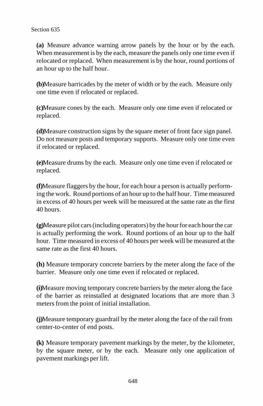
Section 635
648
(a) Measure advance warning arrow panels by the hour or by the each.When measurement is by the each, measure the panels only one time even ifrelocated or replaced. When measurement is by the hour, round portions ofan hour up to the half hour.
(b) Measure barricades by the meter of width or by the each. Measure onlyone time even if relocated or replaced.
(c) Measure cones by the each. Measure only one time even if relocated orreplaced.
(d) Measure construction signs by the square meter of front face sign panel.Do not measure posts and temporary supports. Measure only one time evenif relocated or replaced.
(e) Measure drums by the each. Measure only one time even if relocated orreplaced.
(f) Measure flaggers by the hour, for each hour a person is actually perform-ing the work. Round portions of an hour up to the half hour. Time measuredin excess of 40 hours per week will be measured at the same rate as the first40 hours.
(g) Measure pilot cars (including operators) by the hour for each hour the caris actually performing the work. Round portions of an hour up to the halfhour. Time measured in excess of 40 hours per week will be measured at thesame rate as the first 40 hours.
(h) Measure temporary concrete barriers by the meter along the face of thebarrier. Measure only one time even if relocated or replaced.
(i) Measure moving temporary concrete barriers by the meter along the faceof the barrier as reinstalled at designated locations that are more than 3meters from the point of initial installation.
(j) Measure temporary guardrail by the meter along the face of the rail fromcenter-to-center of end posts.
(k) Measure temporary pavement markings by the meter, by the kilometer,by the square meter, or by the each. Measure only one application ofpavement markings per lift.
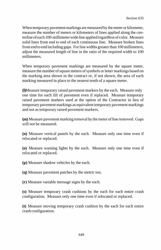
Section 635
649
When temporary pavement markings are measured by the meter or kilometer,measure the number of meters or kilometers of lines applied along the cen-terline of each 100-millimeter wide line applied regardless of color. Measuresolid lines from end to end of each continuous line. Measure broken linesfrom end to end including gaps. For line widths greater than 100 millimeters,adjust the measured length of line in the ratio of the required width to 100millimeters.
When temporary pavement markings are measured by the square meter,measure the number of square meters of symbols or letter markings based onthe marking area shown in the contract or, if not shown, the area of eachmarking measured in place to the nearest tenth of a square meter.
(l) Measure temporary raised pavement markers by the each. Measure onlyone time for each lift of pavement even if replaced. Measure temporaryraised pavement markers used at the option of the Contractor in lieu oftemporary pavement markings as equivalent temporary pavement markingsand not as temporary raised pavement markers.
(m) Measure pavement marking removal by the meter of line removed. Gapswill not be measured.
(n) Measure vertical panels by the each. Measure only one time even ifrelocated or replaced.
(o) Measure warning lights by the each. Measure only one time even ifrelocated or replaced.
(p) Measure shadow vehicles by the each.
(q) Measure pavement patches by the metric ton.
(r) Measure variable message signs by the each.
(s) Measure temporary crash cushions by the each for each entire crashconfiguration. Measure only one time even if relocated or replaced.
(t) Measure moving temporary crash cushion by the each for each entirecrash configuration.
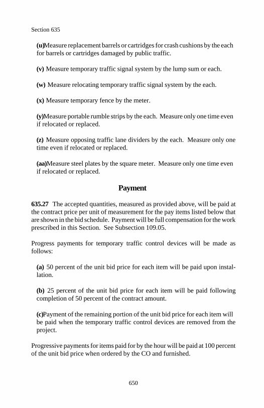
Section 635
650
(u) Measure replacement barrels or cartridges for crash cushions by the eachfor barrels or cartridges damaged by public traffic.
(v) Measure temporary traffic signal system by the lump sum or each.
(w) Measure relocating temporary traffic signal system by the each.
(x) Measure temporary fence by the meter.
(y) Measure portable rumble strips by the each. Measure only one time evenif relocated or replaced.
(z) Measure opposing traffic lane dividers by the each. Measure only onetime even if relocated or replaced.
(aa) Measure steel plates by the square meter. Measure only one time evenif relocated or replaced.
Payment
635.27 The accepted quantities, measured as provided above, will be paid atthe contract price per unit of measurement for the pay items listed below thatare shown in the bid schedule. Payment will be full compensation for the workprescribed in this Section. See Subsection 109.05.
Progress payments for temporary traffic control devices will be made asfollows:
(a) 50 percent of the unit bid price for each item will be paid upon instal-lation.
(b) 25 percent of the unit bid price for each item will be paid followingcompletion of 50 percent of the contract amount.
(c) Payment of the remaining portion of the unit bid price for each item willbe paid when the temporary traffic control devices are removed from theproject.
Progressive payments for items paid for by the hour will be paid at 100 percentof the unit bid price when ordered by the CO and furnished.
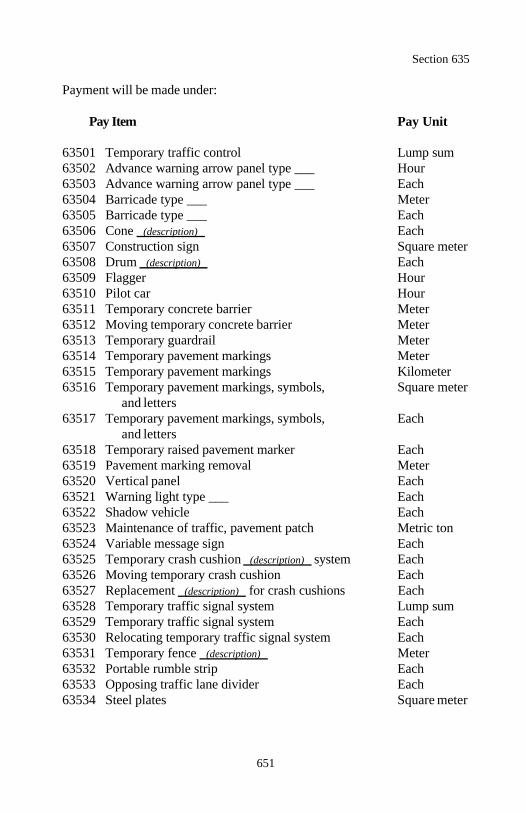
Section 635
651
Payment will be made under:
Pay Item Pay Unit
63501 Temporary traffic control Lump sum63502 Advance warning arrow panel type ___ Hour63503 Advance warning arrow panel type ___ Each63504 Barricade type ___ Meter63505 Barricade type ___ Each63506 Cone (description) Each63507 Construction sign Square meter63508 Drum (description) Each63509 Flagger Hour63510 Pilot car Hour63511 Temporary concrete barrier Meter63512 Moving temporary concrete barrier Meter63513 Temporary guardrail Meter63514 Temporary pavement markings Meter63515 Temporary pavement markings Kilometer63516 Temporary pavement markings, symbols, Square meter
and letters63517 Temporary pavement markings, symbols, Each
and letters63518 Temporary raised pavement marker Each63519 Pavement marking removal Meter63520 Vertical panel Each63521 Warning light type ___ Each63522 Shadow vehicle Each63523 Maintenance of traffic, pavement patch Metric ton63524 Variable message sign Each63525 Temporary crash cushion (description) system Each63526 Moving temporary crash cushion Each63527 Replacement (description) for crash cushions Each63528 Temporary traffic signal system Lump sum63529 Temporary traffic signal system Each63530 Relocating temporary traffic signal system Each63531 Temporary fence (description) Meter63532 Portable rumble strip Each63533 Opposing traffic lane divider Each63534 Steel plates Square meter
652
Section 636.) SIGNAL, LIGHTING,AND ELECTRICAL SYSTEMS
Description
636.01 This work consists of installing, modifying, or removing traffic signals,flashing beacons, highway lighting, sign illumination, communication conduits,and electrical systems or provisions for future systems.
Material
636.02 Conform to the following Subsections:
Backer rod 712.01(g)Electrical material 721.01Lighting material 721.02Sealant 712.01(a)
Construction Requirements
636.03 Regulations and Codes. Furnish material and workmanship con-forming to the standards of the National Electrical Code, local safety code, UL,and the National Electrical Manufacturers Association.
Obtain permits, arrange for inspections, and pay all fees necessary to obtainelectrical service.
Notify the CO, local traffic enforcement agency, local utility company, orrailroad company 7 days before any operational shutdown to coordinateconnections or disconnections to an existing utility or system.
636.04 General. At the preconstruction conference, submit a certified costbreakdown of items involved in the lump sum for use in making progresspayments and price adjustments.
Fifteen days before installation, submit a list of proposed equipment andmaterial. Include the manufacturer's name, size, and identification number ofeach item. Supplement the list with scale drawings, catalog cuts, and wiringdiagrams showing locations and details of equipment and wiring.
The CO will establish the exact locations of the systems.
Section 636
653
Remove structures and obstructions according to Section 203. Salvage allmaterial acceptable for reuse in the work. Perform excavation and backfillwork under Section 209. Construct concrete according to Section 601.
Where roadways are to remain open to traffic and existing systems will bemodified, maintain the existing systems in operation until final connection tothe modified circuit to minimize traffic disruptions.
636.05 Conduit. Cut conduit so the ends are smooth. Connect conduitsections with couplings to butt the ends of both conduits squarely against eachother inside the couplings. Provide a metal expansion and deflection fittingwhere conduit crosses a structural expansion joint.
Install conduits continuous between outlets with a minimum of couplings topermit pulling conductors. Terminate conduit with bell fittings or bushings.Furnish pull wires for conduits designated for future cable installation.
Remove and replace crushed, deformed, or damaged conduit. Maintainconduits clean and dry and protect ends of conduit with plugs, caps, or fittings.
Size pull boxes to provide for termination of the conduit and connection of theconductors.
636.06 Installation of Signal and Lighting Systems. Design the control unitto energize the lighting circuit upon failure of any component of its circuit.Furnish a control with an "on" level adjustable between 11 and 54 lux. Operateluminaires with a series circuit distribution system at a potential not exceeding2400 volts.
Control lights and luminaires by photocell controls. For current less than orequal to 10 amperes, furnish a photocell switch. For current greater than 10amperes, furnish a photocell switch operating a magnetic relay for switchingthe lighting circuit.
636.07 Loop Installation. Do not install loops when the pavement is wet.Saw cut, wire, and seal for loop wires on the same day. Do not allow vehiculartraffic to pass over an open saw cut unless covered by a protective panel.
Section 636
654
Saw clean, smooth, well-defined, 8-millimeter wide, and 45-millimeter deepcuts without damaging the adjacent pavement. Overlap saw cuts to provide fulldepth at all corners. Saw cut the lead-in to the pull box as close as possible tothe edge of pavement. Clean and dry saw cuts according to Subsection502.06(a).
Install the loop wire in one continuous length at the bottom of the cut. Installwithout kinks, curls, or other damage to the wire or its insulation. Replace anydamaged wires. Hold the loop wire in place with 0.6-meter long backer rods.
Where the loop wire crosses a crack or joint, use a plastic sleeve which extends100 millimeters on each side of the crack or joint. Provide extra loop wire inthe sleeve for joint expansion and contraction.
Twist the loop lead-in wires 3 turns per meter from the loop to the pull box.Color code the wires of each loop for identification of separate loops. Coil 1meter of lead-in pair slack in the pull box for each loop.
Before applying sealant, test the loop and lead-in for continuity and resistanceby applying a 1000-volt megger between each end of the loop lead-in and thenearest reliable electrical ground. If no available ground exists, establish aground for the measurement. Record the location and megger readings andsubmit readings and test equipment data. Replace the loop if the meggerreading is less than 10 microohms or the inductance is less than 60microhenries or more than 100 microhenries.
Apply sealant to the saw cuts with the backer rods in place. Apply the sealantin a manner which does not produce air bubbles. Remove excess sealant andfinish level with the pavement. Follow the manufacturer's instructions forsufficient time for the sealant to harden before allowing traffic to cross theloops.
Repeat the resistance and continuity test after sealant is applied. Report thesecond test for comparison with the first report.
636.08 Testing and Demonstration Period. Before energizing any portionof the system, demonstrate that the conductor system is clear and free of allshort circuits, open circuits, and unintentional grounds. Repair or replacefaulty circuits.
Section 636
655
After energizing the system, demonstrate that all electrical components workproperly. Repair or replace faulty electrical components.
After completing electrical component tests, conduct a demonstration test for30 continuous days. Adjust and correct any deficiencies in the system duringthe 30-day demonstration period. If any part of the system is replaced orrepaired, retest that part of the system for an additional 30 days.
636.09 Warranties, Guarantees, and Instruction Sheets. When installa-tions are permanent, deliver manufacturers' warranties, guarantees, instructionsheets, and parts lists at the final inspection.
Upon completion of the work, also submit as-built drawings showing all detailchanges from the original plans.
636.10 Relocations. Use material equivalent to existing material, unlesspresent codes require different or improved material. Existing material may besalvaged and reused, provided all material and installation methods used meetthe requirements of applicable codes and ordinances.
636.11 Acceptance. Material for signal systems, lighting systems, andelectrical systems will be evaluated under Subsections 106.02 and 106.03.
Installation of signal systems, lighting systems, and electrical systems will beevaluated under Subsections 106.02 and 106.04.
Structural excavation and backfill will be evaluated under Section 209.
Concrete will be evaluated under Section 601.
Measurement
636.12 Measure signal installation, lighting installation, electrical installation,railroad crossing system, and relocations by the lump sum.
Measure conduits and electrical conductors (wire) by the meter.
Measure luminaires, poles, and pull boxes by the each.
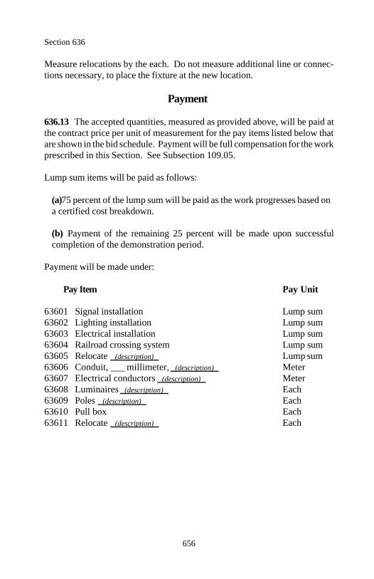
Section 636
656
Measure relocations by the each. Do not measure additional line or connec-tions necessary, to place the fixture at the new location.
Payment
636.13 The accepted quantities, measured as provided above, will be paid atthe contract price per unit of measurement for the pay items listed below thatare shown in the bid schedule. Payment will be full compensation for the workprescribed in this Section. See Subsection 109.05.
Lump sum items will be paid as follows:
(a) 75 percent of the lump sum will be paid as the work progresses based ona certified cost breakdown.
(b) Payment of the remaining 25 percent will be made upon successfulcompletion of the demonstration period.
Payment will be made under:
Pay Item Pay Unit
63601 Signal installation Lump sum63602 Lighting installation Lump sum63603 Electrical installation Lump sum63604 Railroad crossing system Lump sum63605 Relocate (description) Lump sum63606 Conduit, ___ millimeter, (description) Meter63607 Electrical conductors (description) Meter63608 Luminaires (description) Each63609 Poles (description) Each63610 Pull box Each63611 Relocate (description) Each
657
SECTION 637. ) FACILITIES AND SERVICES
Description
637.01 This work consists of furnishing, installing, maintaining, and removingfacilities (including services) such as field offices, field laboratories, andresidential housing for the exclusive use of Government personnel.
Construction Requirements
637.02 General. Provide the facilities and services beginning 14 days beforeproject work begins and ending 21 days after final acceptance. Facilitiesremain the property of the Contractor upon completion of the contract.
Perform all site work to set up and remove facilities. Provide weatherproofbuildings or trailers in good condition. Facilities and their location are subjectto approval. Suitable commercial or private facilities located near the projectmay be provided.
637.03 Facilities. Furnish facilities that are ample, safe, sanitary, and includethe appropriate electrical service, potable water supply, toilet accommodationsand waste disposal services. Pay utility bills (electricity and water) promptlyfor all facilities. When specified in the contract, provide local and longdistance telephone services. The Government will pay the cost of all telephonecalls. Conform to all applicable ordinances, safety codes, and regulations.
(a) Field office. Furnish and maintain a field office according to Tables 637-1 and 637-2.
(b) Field laboratory. Furnish and maintain a field laboratory according toTables 637-1 and 637-2.
When concrete testing is required, furnish a curing tank according toAASHTO M 201 with a minimum capacity for fifty 150 by 300-millimetercylinders. Locate the curing tank for concrete cylinders in a 14-square meteror larger room. The room may be an adjacent separate facility or may be asecond room of the field laboratory.
Equip the tank with a heater and circulator, an outlet for draining the tank,and a separate pressurized water source for filling the tank.
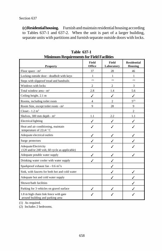
Section 637
658
(c) Residential housing. Furnish and maintain residential housing accordingto Tables 637-1 and 637-2. When the unit is part of a larger building,separate units with partitions and furnish separate outside doors with locks.
Table 637-1Minimum Requirements for Field Facilities
PropertyField Field Residential
Office Laboratory Housing
Floor space - m² 37 28 46
Locking outside door - deadbolt with keys 1 1 1
Steps with slipproof tread and handrails (1) (1) (1)
Windows with locks 2 2 3
Total window area - m² 2.8 1.4 5.6
Ceiling height, 2.1 m
Rooms, including toilet room 4 2 5(2)
Room Size, except toilet room - m² 9 28 9
Closet - 1.2 m 23
Shelves, 300 mm depth - m² 1.1 2.2 1.1
Electrical lighting
Heat and air conditioning, maintain temperature of 22±4 C
Adequate electrical outlets
Surge protectors
Adequate Electricity (120 and/or 240 volt, 60 cycle as applicable)
Adequate potable water supply
Drinking water cooler with water supply
Sparkproof exhaust fan - 0.6 m /s3
Sink, with faucets for both hot and cold water
Adequate hot and cold water supply
Shower/bath facilities
Parking for 3 vehicles on gravel surface
1.8 m high chain link fence with gate around building and parking area
(1) As required.(2) Includes 2 bedrooms.
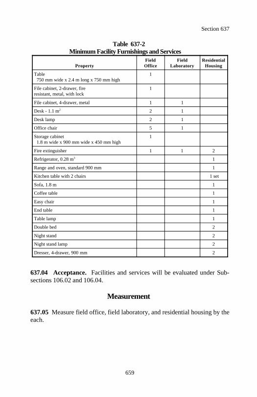
Section 637
659
Table 637-2Minimum Facility Furnishings and Services
PropertyField Field ResidentialOffice Laboratory Housing
Table 1 750 mm wide x 2.4 m long x 750 mm high
File cabinet, 2-drawer, fire 1resistant, metal, with lock
File cabinet, 4-drawer, metal 1 1
Desk - 1.1 m 2 12
Desk lamp 2 1
Office chair 5 1
Storage cabinet 1 1.8 m wide x 900 mm wide x 450 mm high
Fire extinguisher 1 1 2
Refrigerator, 0.28 m 13
Range and oven, standard 900 mm 1
Kitchen table with 2 chairs 1 set
Sofa, 1.8 m 1
Coffee table 1
Easy chair 1
End table 1
Table lamp 1
Double bed 2
Night stand 2
Night stand lamp 2
Dresser, 4-drawer, 900 mm 2
637.04 Acceptance. Facilities and services will be evaluated under Sub-sections 106.02 and 106.04.
Measurement
637.05 Measure field office, field laboratory, and residential housing by theeach.
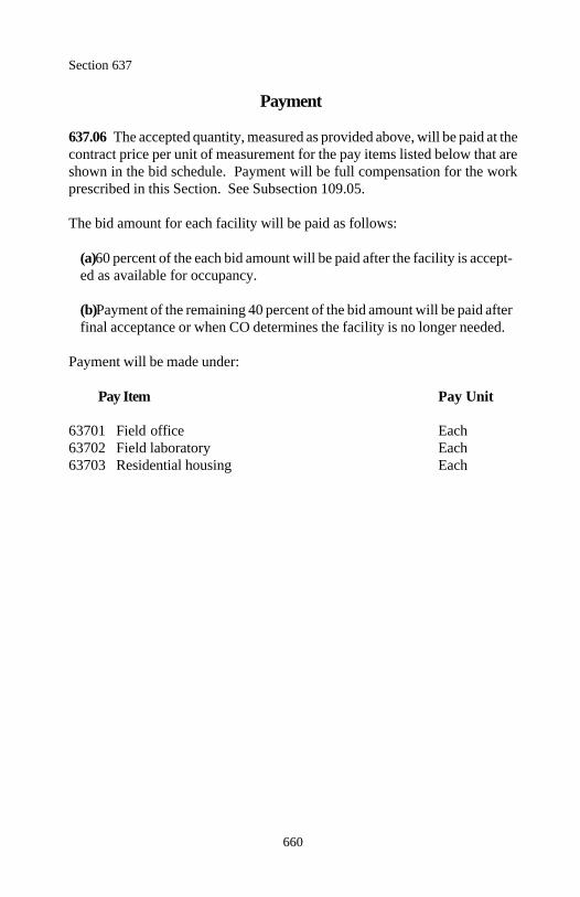
Section 637
660
Payment
637.06 The accepted quantity, measured as provided above, will be paid at thecontract price per unit of measurement for the pay items listed below that areshown in the bid schedule. Payment will be full compensation for the workprescribed in this Section. See Subsection 109.05.
The bid amount for each facility will be paid as follows:
(a) 60 percent of the each bid amount will be paid after the facility is accept-ed as available for occupancy.
(b) Payment of the remaining 40 percent of the bid amount will be paid afterfinal acceptance or when CO determines the facility is no longer needed.
Payment will be made under:
Pay Item Pay Unit
63701 Field office Each63702 Field laboratory Each63703 Residential housing Each
661
DIVISION 700Material
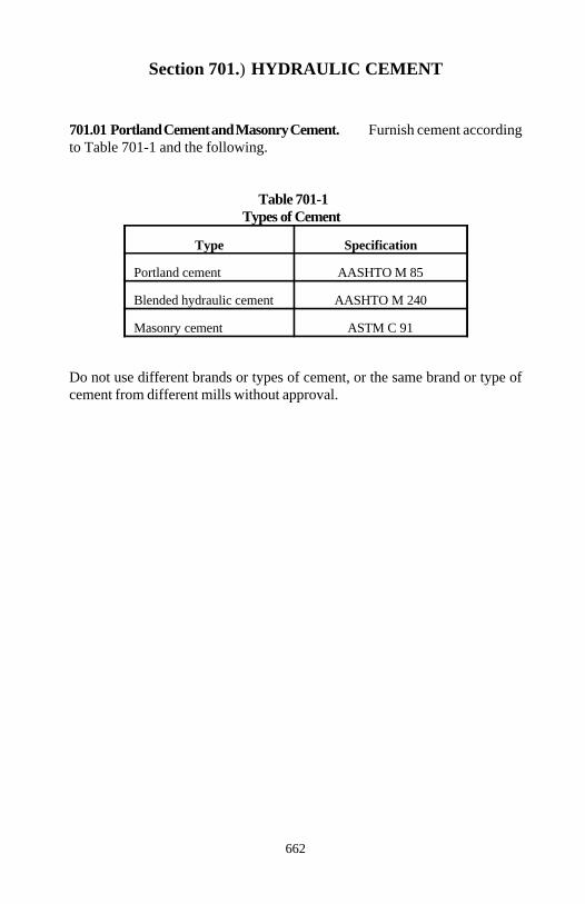
662
Section 701.) HYDRAULIC CEMENT
701.01 Portland Cement and Masonry Cement. Furnish cement accordingto Table 701-1 and the following.
Table 701-1Types of Cement
Type Specification
Portland cement AASHTO M 85
Blended hydraulic cement AASHTO M 240
Masonry cement ASTM C 91
Do not use different brands or types of cement, or the same brand or type ofcement from different mills without approval.
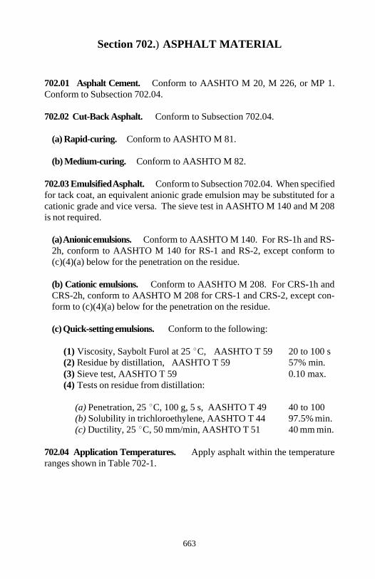
663
Section 702.) ASPHALT MATERIAL
702.01 Asphalt Cement. Conform to AASHTO M 20, M 226, or MP 1.Conform to Subsection 702.04.
702.02 Cut-Back Asphalt. Conform to Subsection 702.04.
(a) Rapid-curing. Conform to AASHTO M 81.
(b) Medium-curing. Conform to AASHTO M 82.
702.03 Emulsified Asphalt. Conform to Subsection 702.04. When specifiedfor tack coat, an equivalent anionic grade emulsion may be substituted for acationic grade and vice versa. The sieve test in AASHTO M 140 and M 208is not required.
(a) Anionic emulsions. Conform to AASHTO M 140. For RS-1h and RS-2h, conform to AASHTO M 140 for RS-1 and RS-2, except conform to(c)(4)(a) below for the penetration on the residue.
(b) Cationic emulsions. Conform to AASHTO M 208. For CRS-1h andCRS-2h, conform to AASHTO M 208 for CRS-1 and CRS-2, except con-form to (c)(4)(a) below for the penetration on the residue.
(c) Quick-setting emulsions. Conform to the following:
(1) Viscosity, Saybolt Furol at 25 C, AASHTO T 59 20 to 100 s(2) Residue by distillation, AASHTO T 59 57% min.(3) Sieve test, AASHTO T 59 0.10 max.(4) Tests on residue from distillation:
(a) Penetration, 25 C, 100 g, 5 s, AASHTO T 49 40 to 100(b) Solubility in trichloroethylene, AASHTO T 44 97.5% min.(c) Ductility, 25 C, 50 mm/min, AASHTO T 51 40 mm min.
702.04 Application Temperatures. Apply asphalt within the temperatureranges shown in Table 702-1.
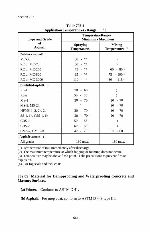
Section 702
664
Table 702-1Application Temperatures - Range C
Type and Grade Minimum - Maximumof
Asphalt
Temperature Ranges
Spraying MixingTemperatures Temperatures (1)
Cut-back asphalt ) MC-30 30 - )(2)
RC or MC-70 50 - )(2)
RC or MC-250 75 - 60 - 80(2) (3)
RC or MC-800 95 - 75 - 100(2) (3)
RC or MC-3000 110 - 80 - 115(2) (3)
Emulsified asphalt ) RS-1 20 - 60 ) RS-2 50 - 85 ) MS-1 20 - 70 20 - 70 MS-2, MS-2h ) 20 - 70 HFMS-1, 2, 2h, 2s 20 - 70 10 - 70 SS-1, 1h, CSS-1, 1h 20 - 70 20 - 70(4)
CRS-1 50 - 85 ) CRS-2 60 - 85 ) CMS-2, CMS-2h 40 - 70 50 - 60
Asphalt cement ) All grades 180 max. 180 max.
(1) Temperature of mix immediately after discharge.(2) The maximum temperature at which fogging or foaming does not occur.(3) Temperature may be above flash point. Take precautions to prevent fire orexplosion.(4) For fog seals and tack coats.
702.05 Material for Dampproofing and Waterproofing Concrete andMasonry Surfaces.
(a) Primer. Conform to ASTM D 41.
(b) Asphalt. For mop coat, conform to ASTM D 449 type III.
Section 702
665
(c) Waterproofing fabric. Furnish asphalt saturated fabric conforming toASTM D 173.
(d) Mortar. Conform to Subsection 712.05 except uniformly mix the mortarto a spreading consistency using volumetric proportions of 1 part portlandcement to 3 parts fine aggregate.
(e) Asphalt plank. Conform to ASTM D 517 and the following:
(1) Thickness. 32 millimeters.
(2) Width. 225±75 millimeters. Use only one width of plank for a singlestructure except for necessary closers.
(3) Length. 1 to 2.5 meters. Use length that permit the laying of planksto the best advantage on the surface to be covered.
(f) Asphalt roll roofing. Conform to ASTM D 224 type II.
702.06 Recycling Agent. Conform to ASTM D 4552 or use an approvedpetroleum product additive that restores aged asphalt to the requiredspecifications.
702.07 Asphalt Mastic. Conform to AASHTO M 243.
702.08 Antistrip Additive. Conform to the following:
(a) Type 1. Furnish commercially produced, heat stable liquid products thatwhen added to an asphalt have the chemical and physical properties toprevent separation of the asphalt from aggregates.
(b) Type 2. Furnish cement conforming to Subsection 701.01 or fly ash con-forming to Subsection 725.04.
(c) Type 3. Furnish lime conforming to Subsection 725.03.
702.09 Evaluation Procedures for Asphalt. Evaluate under Subsection106.04 subject to the following:
Section 702
666
(a) Shipping container. Before loading, examine the shipping container andremove all remnants of previous cargos that may contaminate the asphalt.
(b) Delivery ticket. Furnish with each shipment 2 copies of the deliveryticket containing the following:
(1) Consignees (2) Project number (3) Grade (4) Net volume (5) Net mass (6) Type and amount of antistrip additive (7) Identification number (truck, car, tank, etc.) (8) Destination (9) Date(10) Loading temperature(11) Specific gravity at 15 C
(c) Sampling procedures. Obtain samples of asphalt according to AA-SHTO T 40 at the applicable sampling location as follows:
(1) Asphalt used in direct application on the road. Take samples fromeach shipping container at the time of discharge into distributors or otherconveyances on the project.
(2) Asphalt initially discharged into storage tanks on the project.Take samples from the line between the storage tank and the distributoror the mixing plant after each delivery. Take samples after a sufficientperiod of circulation to ensure samples are representative of the materialin the storage tank.
702.10 Cold Asphalt Mix. Mix crushed stone or gravel, and asphalt in anapproved plant. Conform to aggregate gradation and quality and asphalt gradeand quality specifications normally used in the construction of highways byFederal or state agencies.
Do not use an aggregate asphalt mix that strips. For patching mixes, use anasphalt grade and mix that remains pliable and workable at -10 C.
667
Section 703.) AGGREGATE
703.01 Fine Aggregate for Portland Cement Concrete. Furnish sandconforming to AASHTO M 6 class B including the reactive aggregatesupplementary requirement, except as amended or supplemented by the follow-ing:
(a) Material passing 75- m sieve, AASHTO T 11 3.0% max.(b) Sand equivalent value, AASHTO T 176 75 min.referee method
For lightweight fine aggregate, conform to AASHTO M 195.
703.02 Coarse Aggregate for Portland Cement Concrete. Conform toAASHTO M 80 class A, except as amended or supplemented by the following:
(a) Los Angeles abrasion, AASHTO T 96 40% max.(b) Adherent coating, FLH T 512 1.0% max.
For bridge decks or surface courses, do not use aggregates known to polish orcarbonate aggregates containing less than 25 percent by mass of insolubleresidue as determined by ASTM D 3042.
For lightweight coarse aggregate, conform to AASHTO M 195.
703.03 Granular Backfill. Furnish aggregate for the following instal-lations.
(a) Underdrain pipe with geotextile. Furnish granular backfill conformingto AASHTO M 80 class E and AASHTO M 43 no. 3, 4, 5, 7, 57, or 67.
(b) Underdrain pipe without geotextile. Furnish granular backfill con-forming to AASHTO M 6, except the soundness test is not required.
703.04 Permeable Backfill. Furnish either sand conforming to Subsection703.15 or coarse aggregate consisting of sound, durable particles of gravel,slag, or crushed stone conforming to Table 703-1.
Table 703 - 1Permeable Backfill Gradation
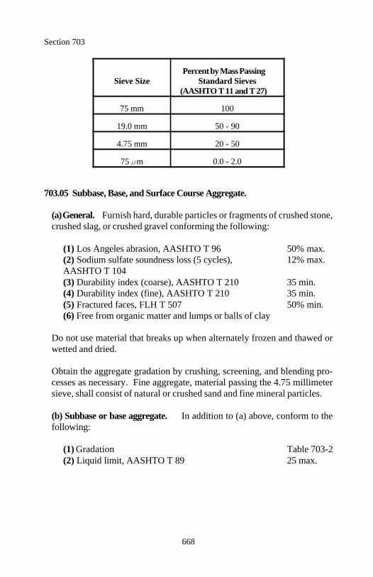
Section 703
668
Sieve Size Standard SievesPercent by Mass Passing
(AASHTO T 11 and T 27)
75 mm 100
19.0 mm 50 - 90
4.75 mm 20 - 50
75 m 0.0 - 2.0
703.05 Subbase, Base, and Surface Course Aggregate.
(a) General. Furnish hard, durable particles or fragments of crushed stone,crushed slag, or crushed gravel conforming the following:
(1) Los Angeles abrasion, AASHTO T 96 50% max.(2) Sodium sulfate soundness loss (5 cycles), 12% max.AASHTO T 104(3) Durability index (coarse), AASHTO T 210 35 min.(4) Durability index (fine), AASHTO T 210 35 min.(5) Fractured faces, FLH T 507 50% min.(6) Free from organic matter and lumps or balls of clay
Do not use material that breaks up when alternately frozen and thawed orwetted and dried.
Obtain the aggregate gradation by crushing, screening, and blending pro-cesses as necessary. Fine aggregate, material passing the 4.75 millimetersieve, shall consist of natural or crushed sand and fine mineral particles.
(b) Subbase or base aggregate. In addition to (a) above, conform to thefollowing:
(1) Gradation Table 703-2(2) Liquid limit, AASHTO T 89 25 max.
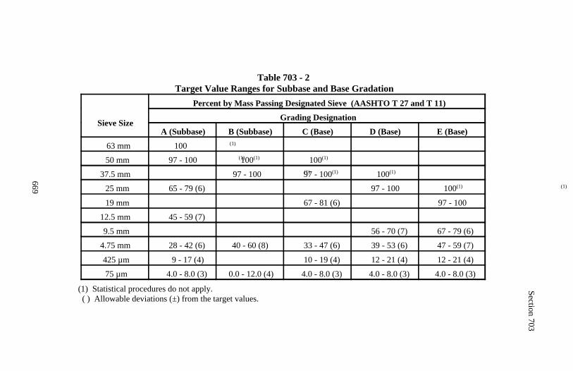
Section 703
669
Table 703 - 2Target Value Ranges for Subbase and Base Gradation
Sieve Size
Percent by Mass Passing Designated Sieve (AASHTO T 27 and T 11)
Grading Designation
A (Subbase) B (Subbase) C (Base) D (Base) E (Base)
63 mm 100 (1)
50 mm 97 - 100 (1)100(1) 100(1)
37.5 mm 97 - 100 (1) 97 - 100(1) 100(1)
25 mm 65 - 79 (6) 97 - 100 (1) 100(1)
19 mm 67 - 81 (6) 97 - 100
12.5 mm 45 - 59 (7)
9.5 mm 56 - 70 (7) 67 - 79 (6)
4.75 mm 28 - 42 (6) 40 - 60 (8) 33 - 47 (6) 39 - 53 (6) 47 - 59 (7)
425 µm 9 - 17 (4) 10 - 19 (4) 12 - 21 (4) 12 - 21 (4)
75 µm 4.0 - 8.0 (3) 0.0 - 12.0 (4) 4.0 - 8.0 (3) 4.0 - 8.0 (3) 4.0 - 8.0 (3)
(1) Statistical procedures do not apply.( ) Allowable deviations (±) from the target values.
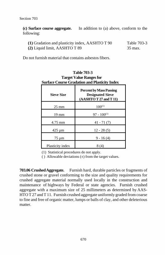
Section 703
670
(c) Surface course aggregate. In addition to (a) above, conform to thefollowing:
(1) Gradation and plasticity index, AASHTO T 90 Table 703-3(2) Liquid limit, AASHTO T 89 35 max.
Do not furnish material that contains asbestos fibers.
Table 703-3Target Value Ranges for
Surface Course Gradation and Plasticity Index
Sieve Size Designated SievePercent by Mass Passing
(AASHTO T 27 and T 11)
25 mm 100(1)
19 mm 97 - 100(1)
4.75 mm 41 - 71 (7)
425 µm 12 - 28 (5)
75 µm 9 - 16 (4)
Plasticity index 8 (4)
(1) Statistical procedures do not apply.( ) Allowable deviations (±) from the target values.
703.06 Crushed Aggregate. Furnish hard, durable particles or fragments ofcrushed stone or gravel conforming to the size and quality requirements forcrushed aggregate material normally used locally in the construction andmaintenance of highways by Federal or state agencies. Furnish crushedaggregate with a maximum size of 25 millimeters as determined by AAS-HTO T 27 and T 11. Furnish crushed aggregate uniformly graded from coarseto fine and free of organic matter, lumps or balls of clay, and other deleteriousmatter.
Section 703
671
703.07 Hot Asphalt Concrete Pavement Aggregate.
(a) Coarse aggregate (retained on a 4.75-millimeter sieve). Furnish hard,durable particles or fragments of crushed stone, crushed slag, or crushedgravel conforming to the following:
(1) Los Angeles abrasion, AASHTO T 96 40% max.(2) Sodium sulfate soundness loss (5 cycles), 12% max.AASHTO T 104(3) Fractured faces, FLH T 507 75% min.(4) Durability index (coarse), AASHTO T 210 35 min.
For the surface course, do not use aggregates known to polish or carbonateaggregates containing less than 25 percent by mass of insoluble residue whentested according to ASTM D 3042.
(b) Fine aggregate (passing a 4.75-millimeter sieve). Furnish natural sand,stone screenings, slag screenings, or a combination thereof conforming toAASHTO M 29 including sulfate soundness and the following:
(1) Durability index (fine), AASHTO T 210 35 min.(2) Sand equivalent value, AASHTO T 176 45 min.referee method
(c) Composite aggregate blend. Size, grade, and combine the aggregatefractions in mix proportions conforming to the following:
(1) Gradation Table 703-4(2) Clay lumps and friable particles, AASHTO T 112 1.0% max.(3) Reasonably free from organic or other deleterious material
(d) Lightweight aggregate (slag). Furnish crushed slag conforming to thequality requirements of AASHTO M 195. Do not use any other kind or typeof lightweight aggregate as defined in AASHTO M 195.
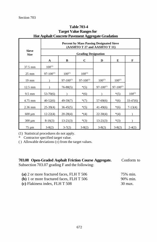
Section 703
672
Table 703-4Target Value Ranges for
Hot Asphalt Concrete Pavement Aggregate Gradation
SieveSize
Percent by Mass Passing Designated Sieve (AASHTO T 27 and AASHTO T 11)
Grading Designation
A B C D E F
37.5 mm 100(1)
25 mm 97-100 100 100(1) (1) (1)
19 mm ) 97-100 97-100 100 100(1) (1) (1) (1)
12.5 mm ) 76-88(5) *(5) 97-100 97-100(1) (1)
9.5 mm 53-70(6) ) *(6) ) *(5) 100(1)
4.75 mm 40-52(6) 49-59(7) *(7) 57-69(6) *(6) 33-47(6)
2.36 mm 25-39(4) 36-45(5) *(5) 41-49(6) *(6) 7-13(4)
600 µm 12-22(4) 20-28(4) *(4) 22-30(4) *(4) )
300 µm 8-16(3) 13-21(3) *(3) 13-21(3) *(3) )
75 µm 3-8(2) 3-7(2) 3-8(2) 3-8(2) 3-8(2) 2-4(2)
(1) Statistical procedures do not apply.* Contractor specified target value.( ) Allowable deviations (±) from the target values.
703.08 Open-Graded Asphalt Friction Course Aggregate. Conform toSubsection 703.07 grading F and the following:
(a) 2 or more fractured faces, FLH T 506 75% min.(b) 1 or more fractured faces, FLH T 506 90% min.(c) Flakiness index, FLH T 508 30 max.
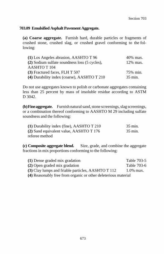
Section 703
673
703.09 Emulsified Asphalt Pavement Aggregate.
(a) Coarse aggregate. Furnish hard, durable particles or fragments ofcrushed stone, crushed slag, or crushed gravel conforming to the fol-lowing:
(1) Los Angeles abrasion, AASHTO T 96 40% max.(2) Sodium sulfate soundness loss (5 cycles), 12% max.AASHTO T 104(3) Fractured faces, FLH T 507 75% min.(4) Durability index (coarse), AASHTO T 210 35 min.
Do not use aggregates known to polish or carbonate aggregates containingless than 25 percent by mass of insoluble residue according to ASTMD 3042.
(b) Fine aggregate. Furnish natural sand, stone screenings, slag screenings,or a combination thereof conforming to AASHTO M 29 including sulfatesoundness and the following:
(1) Durability index (fine), AASHTO T 210 35 min.(2) Sand equivalent value, AASHTO T 176 35 min.referee method
(c) Composite aggregate blend. Size, grade, and combine the aggregatefractions in mix proportions conforming to the following:
(1) Dense graded mix gradation Table 703-5(2) Open graded mix gradation Table 703-6(3) Clay lumps and friable particles, AASHTO T 112 1.0% max.(4) Reasonably free from organic or other deleterious material
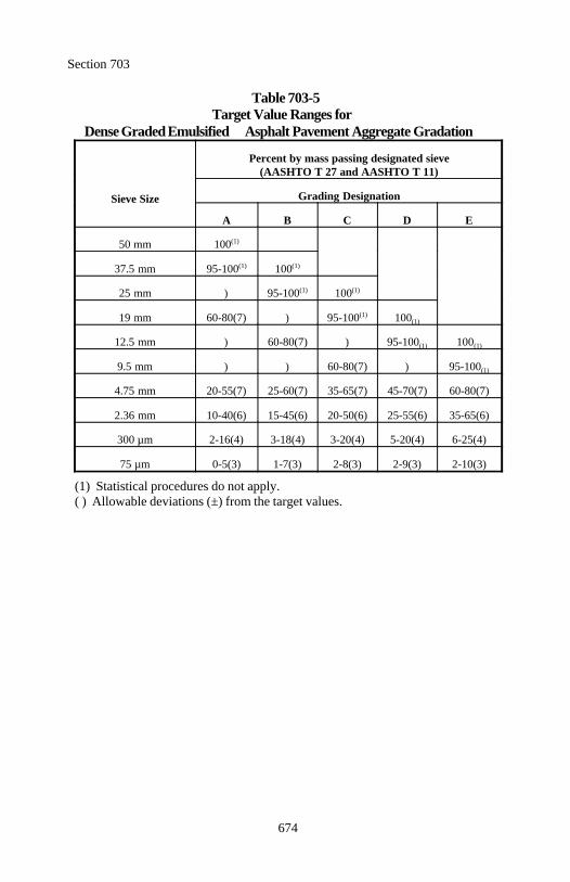
Section 703
674
Table 703-5Target Value Ranges for
Dense Graded Emulsified Asphalt Pavement Aggregate Gradation
Sieve Size
Percent by mass passing designated sieve(AASHTO T 27 and AASHTO T 11)
Grading Designation
A B C D E
50 mm 100(1)
37.5 mm 95-100 100(1) (1)
25 mm ) 95-100 100(1) (1)
19 mm 60-80(7) ) 95-100 100(1)(1)
12.5 mm ) 60-80(7) ) 95-100 100(1) (1)
9.5 mm ) ) 60-80(7) ) 95-100(1)
4.75 mm 20-55(7) 25-60(7) 35-65(7) 45-70(7) 60-80(7)
2.36 mm 10-40(6) 15-45(6) 20-50(6) 25-55(6) 35-65(6)
300 µm 2-16(4) 3-18(4) 3-20(4) 5-20(4) 6-25(4)
75 µm 0-5(3) 1-7(3) 2-8(3) 2-9(3) 2-10(3)
(1) Statistical procedures do not apply.( ) Allowable deviations (±) from the target values.
Section 703
675
Table 703-6Target Value Ranges for
Open Graded Emulsified Asphalt Pavement Aggregate Gradation
Sieve Size
Percent by mass passing designated sieve(AASHTO T 27 and AASHTO T 11)
Grading Designation
A B C D
37.5 mm 100(1)
25 mm 95-100 100(1) (1)
19 mm ) 95-100 100(1) (1)
12.5 mm 25-65(7) ) 95-100 100(1) (1)
9.5 mm ) 20-55(7) 35-40(7) 85-100(7)
4.25 mm 0-10(5) 0-10(5) - )
2.36 mm 0-5(3) 0-5(3) 3-7(3) )
1.18 mm ) ) - 0-5(3)
75 µm 0-2(1) 0-2(1) 0-1(1) 0-2(1)
(1) Statistical procedures do not apply.( ) Allowable deviations (±) from the target values.
703.10 Asphalt Surface Treatment Aggregate. Furnish hard, durable parti-cles or fragments of crushed stone, crushed slag, or crushed gravel. Use onlyone type of aggregate on a project.
Size, grade, and combine the aggregate fractions in mix proportions con-forming to the following:
(a) Gradation Table 703-7(b) Los Angeles abrasion, AASHTO T 96 40% max.(c) Sodium sulfate soundness loss, 12% max.
AASHTO T 104(d) Density, AASHTO T 19M 1100 kg/m min. 3
(e) Coating and stripping of bitumen-aggregate 95% min. mixtures, AASHTO T 182
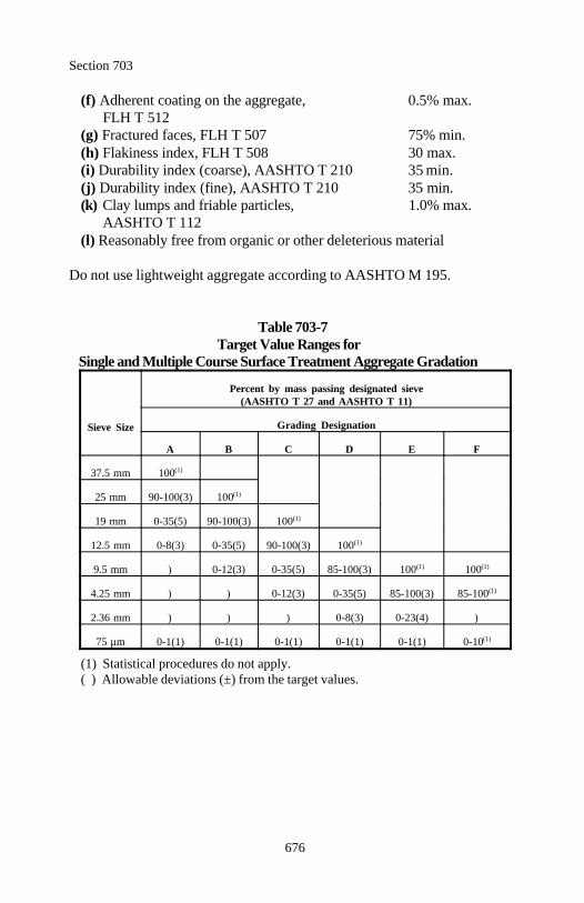
Section 703
676
(f) Adherent coating on the aggregate, 0.5% max. FLH T 512
(g) Fractured faces, FLH T 507 75% min.(h) Flakiness index, FLH T 508 30 max.(i) Durability index (coarse), AASHTO T 210 35 min.(j) Durability index (fine), AASHTO T 210 35 min.(k) Clay lumps and friable particles, 1.0% max.
AASHTO T 112(l) Reasonably free from organic or other deleterious material
Do not use lightweight aggregate according to AASHTO M 195.
Table 703-7Target Value Ranges for
Single and Multiple Course Surface Treatment Aggregate Gradation
Sieve Size
Percent by mass passing designated sieve(AASHTO T 27 and AASHTO T 11)
Grading Designation
A B C D E F
37.5 mm 100(1)
25 mm 90-100(3) 100(1)
19 mm 0-35(5) 90-100(3) 100(1)
12.5 mm 0-8(3) 0-35(5) 90-100(3) 100(1)
9.5 mm ) 0-12(3) 0-35(5) 85-100(3) 100 100(1) (1)
4.25 mm ) ) 0-12(3) 0-35(5) 85-100(3) 85-100(1)
2.36 mm ) ) ) 0-8(3) 0-23(4) )
75 µm 0-1(1) 0-1(1) 0-1(1) 0-1(1) 0-1(1) 0-10(1)
(1) Statistical procedures do not apply.( ) Allowable deviations (±) from the target values.
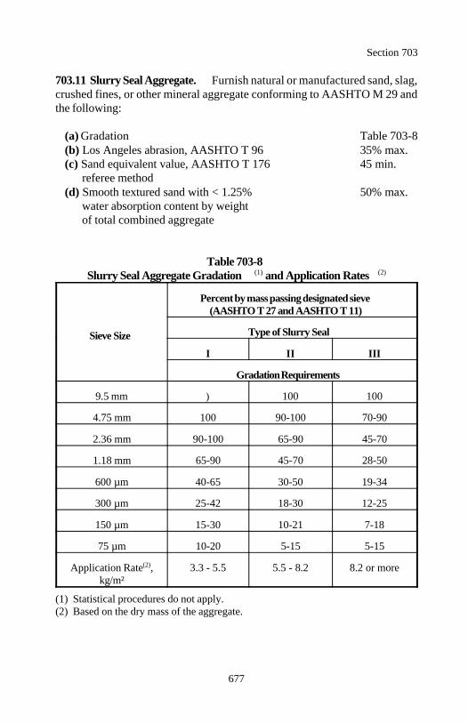
Section 703
677
703.11 Slurry Seal Aggregate. Furnish natural or manufactured sand, slag,crushed fines, or other mineral aggregate conforming to AASHTO M 29 andthe following:
(a) Gradation Table 703-8(b) Los Angeles abrasion, AASHTO T 96 35% max.(c) Sand equivalent value, AASHTO T 176 45 min.
referee method(d) Smooth textured sand with < 1.25% 50% max.
water absorption content by weight of total combined aggregate
Table 703-8Slurry Seal Aggregate Gradation and Application Rates(1) (2)
Sieve Size
Percent by mass passing designated sieve(AASHTO T 27 and AASHTO T 11)
Type of Slurry Seal
I II III
Gradation Requirements
9.5 mm ) 100 100
4.75 mm 100 90-100 70-90
2.36 mm 90-100 65-90 45-70
1.18 mm 65-90 45-70 28-50
600 µm 40-65 30-50 19-34
300 µm 25-42 18-30 12-25
150 µm 15-30 10-21 7-18
75 µm 10-20 5-15 5-15
Application Rate , 3.3 - 5.5 5.5 - 8.2 8.2 or more(2)
kg/m²
(1) Statistical procedures do not apply.(2) Based on the dry mass of the aggregate.
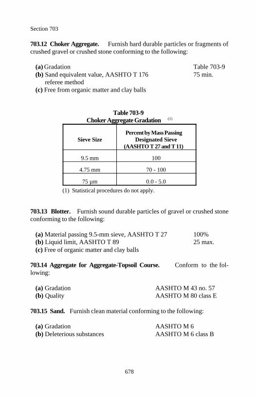
Section 703
678
703.12 Choker Aggregate. Furnish hard durable particles or fragments ofcrushed gravel or crushed stone conforming to the following:
(a) Gradation Table 703-9(b) Sand equivalent value, AASHTO T 176 75 min.
referee method(c) Free from organic matter and clay balls
Table 703-9Choker Aggregate Gradation (1)
Sieve Size Designated SievePercent by Mass Passing
(AASHTO T 27 and T 11)
9.5 mm 100
4.75 mm 70 - 100
75 µm 0.0 - 5.0(1) Statistical procedures do not apply.
703.13 Blotter. Furnish sound durable particles of gravel or crushed stoneconforming to the following:
(a) Material passing 9.5-mm sieve, AASHTO T 27 100%(b) Liquid limit, AASHTO T 89 25 max.(c) Free of organic matter and clay balls
703.14 Aggregate for Aggregate-Topsoil Course. Conform to the fol-lowing:
(a) Gradation AASHTO M 43 no. 57 (b) Quality AASHTO M 80 class E
703.15 Sand. Furnish clean material conforming to the following:
(a) Gradation AASHTO M 6(b) Deleterious substances AASHTO M 6 class B
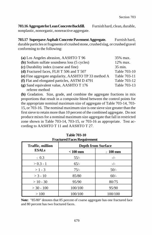
Section 703
679
703.16 Aggregate for Lean Concrete Backfill. Furnish hard, clean, durable,nonplastic, nonorganic, nonreactive aggregate.
703.17 Superpave Asphalt Concrete Pavement Aggregate. Furnish hard,durable particles or fragments of crushed stone, crushed slag, or crushed gravelconforming to the following:
(a) Los Angeles abrasion, AASHTO T 96 35% max.(b) Sodium sulfate soundness loss (5 cycles) 12% max.(c) Durability index (coarse and fine) 35 min.(d) Fractured faces, FLH T 506 and T 507 Table 703-10(e) Fine aggregate angularity, AASHTO TP 33 method A Table 703-11(f) Flat and elongated particles, ASTM D 4791 Table 703-12(g) Sand equivalent value, AASHTO T 176 Table 703-13
referee method(h) Gradation. Size, grade, and combine the aggregate fractions in mixproportions that result in a composite blend between the control points forthe appropriate nominal maximum size of aggregate of Table 703-14, 703-15, or 703-16. The nominal maximum size is one sieve size greater than thefirst sieve to retain more than 10 percent of the combined aggregate. Do notproduce mixes for a nominal maximum size aggregate that fall in restrictedzone shown in Table 703-14, 703-15, or 703-16 as appropriate. Test ac-cording to AASHTO T 11 and AASHTO T 27.
Table 703-10Fractured Faces Requirement
Traffic, million Depth from SurfaceESALs < 100 mm 100 mm
0.3 55/- -/-
> 0.3 - 1 65/- -/-> 1 - 3 75/- 50/-
> 3 - 10 85/80 60/-> 10 - 30 95/90 80/75
> 30 - 100 100/100 95/90> 100 100/100 100/100
Note: "85/80" denotes that 85 percent of coarse aggregate has one fractured faceand 80 percent has two fractured faces.
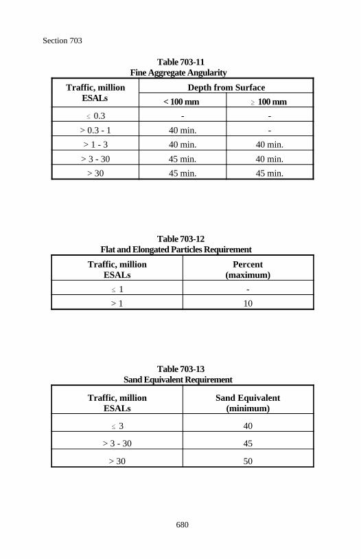
Section 703
680
Table 703-11Fine Aggregate Angularity
Traffic, million Depth from SurfaceESALs < 100 mm 100 mm
0.3 - -
> 0.3 - 1 40 min. -> 1 - 3 40 min. 40 min.
> 3 - 30 45 min. 40 min.> 30 45 min. 45 min.
Table 703-12Flat and Elongated Particles Requirement
Traffic, million PercentESALs (maximum)
1 -> 1 10
Table 703-13Sand Equivalent Requirement
Traffic, million Sand EquivalentESALs (minimum)
3 40
> 3 - 30 45
> 30 50
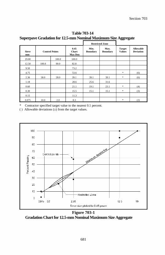
Section 703
681
Table 703-14Superpave Gradation for 12.5-mm Nominal Maximum Size Aggregate
Restricted Zone
Sieve Control Points Chart Boundary Boundary Values Deviationmm Max Den
0.45 Min. Max. Target Allowable
19.00 100.0 100.0
12.50 100.0 90.0 82.8
9.50 73.2
4.75 53.6 * (6)
2.36 58.0 28.0 39.1 39.1 39.1 * (6)
1.18 28.6 25.6 31.6
0.60 21.1 19.1 23.1 * (4)
0.30 15.5 15.1 15.1 * (3)
0.15 11.3
0.075 10.0 2.0 8.3 * (2)
* Contractor specified target value to the nearest 0.1 percent.( ) Allowable deviations (±) from the target values.
Figure 703-1Gradation Chart for 12.5-mm Nominal Maximum Size Aggregate
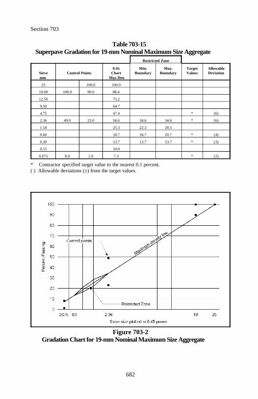
Section 703
682
Table 703-15Superpave Gradation for 19-mm Nominal Maximum Size Aggregate
Restricted Zone
Sieve Control Points Chart Boundary Boundary Values Deviationmm Max Den
0.45 Min. Max. Target Allowable
25 100.0 100.0
19.00 100.0 90.0 88.4
12.50 73.2
9.50 64.7
4.75 47.4 * (6)
2.36 49.0 23.0 34.6 34.6 34.6 * (6)
1.18 25.3 22.3 28.3
0.60 18.7 16.7 20.7 * (4)
0.30 13.7 13.7 13.7 * (3)
0.15 10.0
0.075 8.0 2.0 7.3 * (2)
* Contractor specified target value to the nearest 0.1 percent.( ) Allowable deviations (±) from the target values.
Figure 703-2Gradation Chart for 19-mm Nominal Maximum Size Aggregate
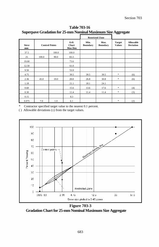
Section 703
683
Table 703-16Superpave Gradation for 25-mm Nominal Maximum Size Aggregate
Restricted Zone
Sieve Control Points Chart Boundary Boundary Values Deviationmm Max Den
0.45 Min. Max. Target Allowable
37.5 100.0 100.0
25 100.0 90.0 83.3
19.00 73.6
12.50 61.0
9.50 53.9
4.75 39.5 39.5 39.5 * (6)
2.36 45.0 19.0 28.8 26.8 30.8 * (6)
1.18 21.1 18.1 24.1
0.60 15.6 13.6 17.6 * (4)
0.30 11.4 11.4 11.4 * (3)
0.15 8.3
0.075 7.0 1.0 6.1 * (2)
* Contractor specified target value to the nearest 0.1 percent.( ) Allowable deviations (±) from the target values.
Figure 703-3Gradation Chart for 25-mm Nominal Maximum Size Aggregate
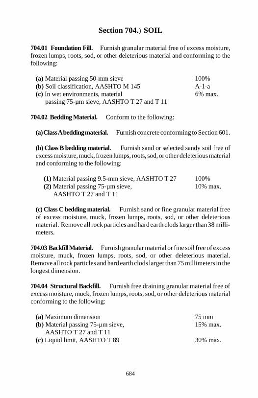
684
Section 704.) SOIL
704.01 Foundation Fill. Furnish granular material free of excess moisture,frozen lumps, roots, sod, or other deleterious material and conforming to thefollowing:
(a) Material passing 50-mm sieve 100%(b) Soil classification, AASHTO M 145 A-1-a(c) In wet environments, material 6% max.
passing 75-µm sieve, AASHTO T 27 and T 11
704.02 Bedding Material. Conform to the following:
(a) Class A bedding material. Furnish concrete conforming to Section 601.
(b) Class B bedding material. Furnish sand or selected sandy soil free ofexcess moisture, muck, frozen lumps, roots, sod, or other deleterious materialand conforming to the following:
(1) Material passing 9.5-mm sieve, AASHTO T 27 100%(2) Material passing 75-µm sieve, 10% max.
AASHTO T 27 and T 11
(c) Class C bedding material. Furnish sand or fine granular material freeof excess moisture, muck, frozen lumps, roots, sod, or other deleteriousmaterial. Remove all rock particles and hard earth clods larger than 38 milli-meters.
704.03 Backfill Material. Furnish granular material or fine soil free of excessmoisture, muck, frozen lumps, roots, sod, or other deleterious material.Remove all rock particles and hard earth clods larger than 75 millimeters in thelongest dimension.
704.04 Structural Backfill. Furnish free draining granular material free ofexcess moisture, muck, frozen lumps, roots, sod, or other deleterious materialconforming to the following:
(a) Maximum dimension 75 mm(b) Material passing 75-µm sieve, 15% max.
AASHTO T 27 and T 11(c) Liquid limit, AASHTO T 89 30% max.
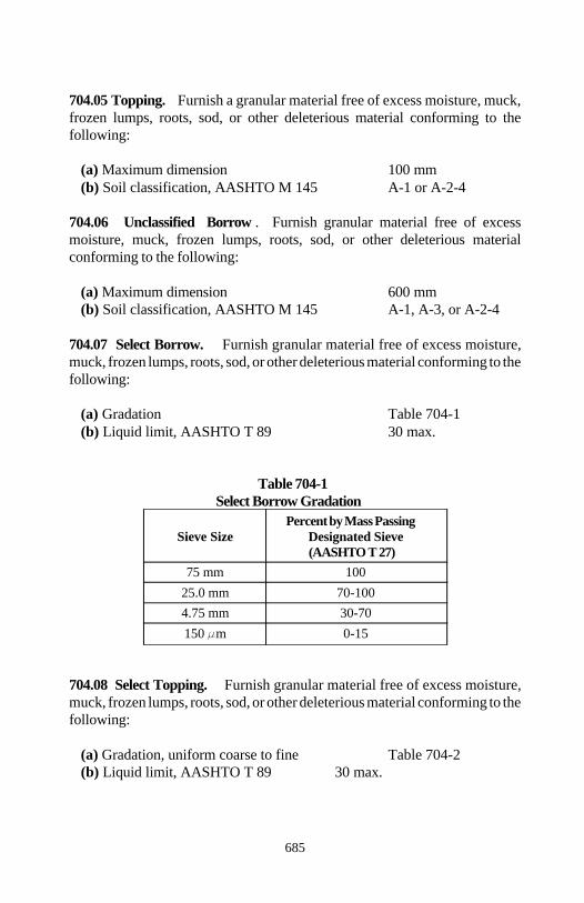
Section 704
685
704.05 Topping. Furnish a granular material free of excess moisture, muck,frozen lumps, roots, sod, or other deleterious material conforming to thefollowing:
(a) Maximum dimension 100 mm(b) Soil classification, AASHTO M 145 A-1 or A-2-4
704.06 Unclassified Borrow . Furnish granular material free of excessmoisture, muck, frozen lumps, roots, sod, or other deleterious materialconforming to the following:
(a) Maximum dimension 600 mm(b) Soil classification, AASHTO M 145 A-1, A-3, or A-2-4
704.07 Select Borrow. Furnish granular material free of excess moisture,muck, frozen lumps, roots, sod, or other deleterious material conforming to thefollowing:
(a) Gradation Table 704-1(b) Liquid limit, AASHTO T 89 30 max.
Table 704-1Select Borrow Gradation
Sieve Size Designated SievePercent by Mass Passing
(AASHTO T 27)75 mm 100
25.0 mm 70-1004.75 mm 30-70150 m 0-15
704.08 Select Topping. Furnish granular material free of excess moisture,muck, frozen lumps, roots, sod, or other deleterious material conforming to thefollowing:
(a) Gradation, uniform coarse to fine Table 704-2(b) Liquid limit, AASHTO T 89 30 max.
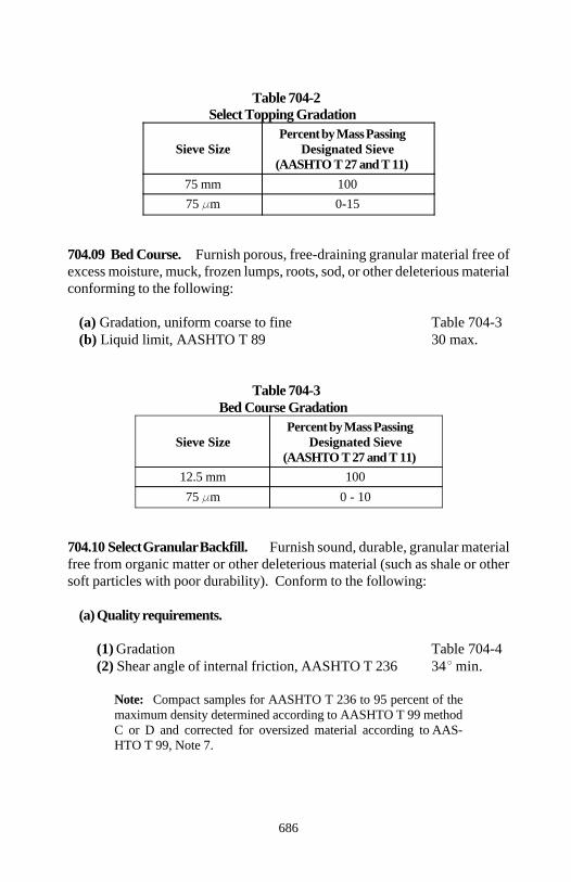
Section 704
686
Table 704-2Select Topping Gradation
Sieve Size Designated SievePercent by Mass Passing
(AASHTO T 27 and T 11)75 mm 10075 m 0-15
704.09 Bed Course. Furnish porous, free-draining granular material free ofexcess moisture, muck, frozen lumps, roots, sod, or other deleterious materialconforming to the following:
(a) Gradation, uniform coarse to fine Table 704-3(b) Liquid limit, AASHTO T 89 30 max.
Table 704-3Bed Course Gradation
Sieve Size Designated SievePercent by Mass Passing
(AASHTO T 27 and T 11)12.5 mm 10075 m 0 - 10
704.10 Select Granular Backfill. Furnish sound, durable, granular materialfree from organic matter or other deleterious material (such as shale or othersoft particles with poor durability). Conform to the following:
(a) Quality requirements.
(1) Gradation Table 704-4(2) Shear angle of internal friction, AASHTO T 236 34 min.
Note: Compact samples for AASHTO T 236 to 95 percent of themaximum density determined according to AASHTO T 99 methodC or D and corrected for oversized material according to AAS-HTO T 99, Note 7.
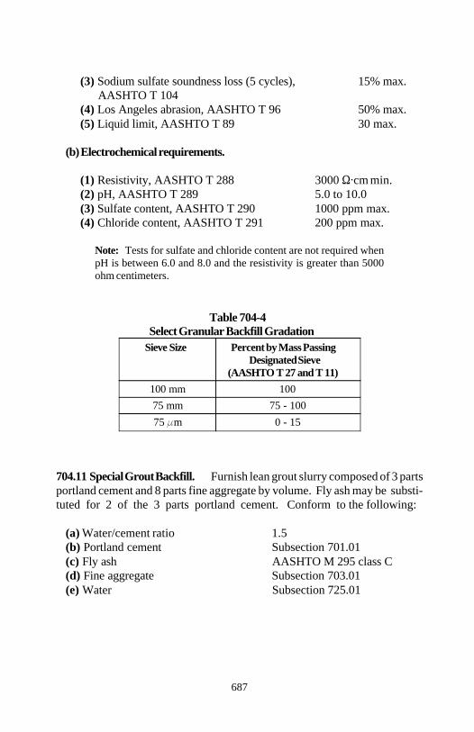
Section 704
687
(3) Sodium sulfate soundness loss (5 cycles), 15% max. AASHTO T 104
(4) Los Angeles abrasion, AASHTO T 96 50% max.(5) Liquid limit, AASHTO T 89 30 max.
(b) Electrochemical requirements.
(1) Resistivity, AASHTO T 288 3000 cm min.(2) pH, AASHTO T 289 5.0 to 10.0(3) Sulfate content, AASHTO T 290 1000 ppm max.(4) Chloride content, AASHTO T 291 200 ppm max.
Note: Tests for sulfate and chloride content are not required whenpH is between 6.0 and 8.0 and the resistivity is greater than 5000ohm centimeters.
Table 704-4Select Granular Backfill Gradation
Sieve Size Percent by Mass PassingDesignated Sieve
(AASHTO T 27 and T 11)100 mm 10075 mm 75 - 10075 m 0 - 15
704.11 Special Grout Backfill. Furnish lean grout slurry composed of 3 partsportland cement and 8 parts fine aggregate by volume. Fly ash may be substi-tuted for 2 of the 3 parts portland cement. Conform to the following:
(a) Water/cement ratio 1.5(b) Portland cement Subsection 701.01(c) Fly ash AASHTO M 295 class C(d) Fine aggregate Subsection 703.01(e) Water Subsection 725.01
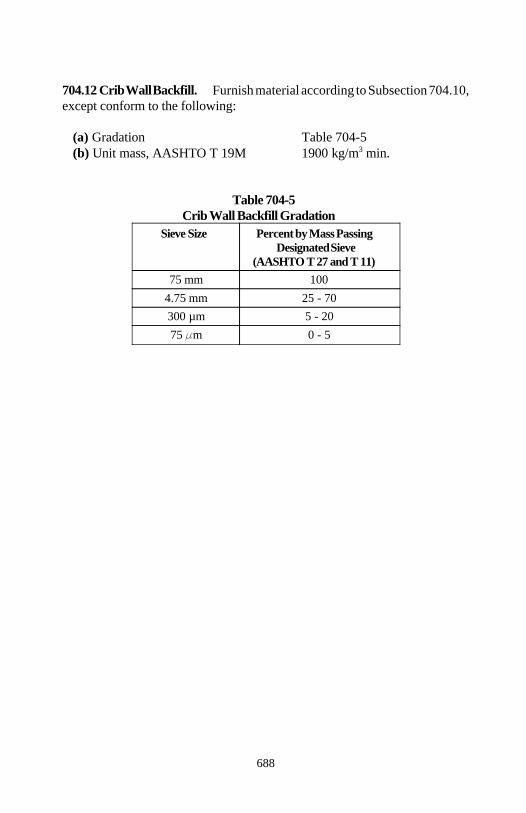
Section 704
688
704.12 Crib Wall Backfill. Furnish material according to Subsection 704.10,except conform to the following:
(a) Gradation Table 704-5(b) Unit mass, AASHTO T 19M 1900 kg/m min.3
Table 704-5Crib Wall Backfill Gradation
Sieve Size Percent by Mass PassingDesignated Sieve
(AASHTO T 27 and T 11)75 mm 100
4.75 mm 25 - 70300 µm 5 - 2075 m 0 - 5
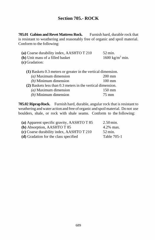
689
Section 705.- ROCK
705.01 Gabion and Revet Mattress Rock. Furnish hard, durable rock thatis resistant to weathering and reasonably free of organic and spoil material.Conform to the following:
(a) Coarse durability index, AASHTO T 210 52 min.(b) Unit mass of a filled basket 1600 kg/m min.3
(c) Gradation:
(1) Baskets 0.3 meters or greater in the vertical dimension.(a) Maximum dimension 200 mm(b) Minimum dimension 100 mm
(2) Baskets less than 0.3 meters in the vertical dimension.(a) Maximum dimension 150 mm(b) Minimum dimension 75 mm
705.02 Riprap Rock. Furnish hard, durable, angular rock that is resistant toweathering and water action and free of organic and spoil material. Do not useboulders, shale, or rock with shale seams. Conform to the following:
(a) Apparent specific gravity, AASHTO T 85 2.50 min.(b) Absorption, AASHTO T 85 4.2% max.(c) Coarse durability index, AASHTO T 210 52 min.(d) Gradation for the class specified Table 705-1
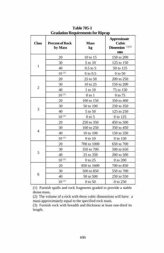
Section 705
690
Table 705-1Gradation Requirements for Riprap
Class Percent of Rock Mass Cubicby Mass kg Dimension
Approximate
(2)(3)
mm
1
20 10 to 15 150 to 20030 5 to 10 125 to 15040 0.5 to 5 50 to 125
10 0 to 0.5 0 to 50(1)
2
20 25 to 50 200 to 25030 10 to 25 150 to 20040 1 to 10 75 to 150
10 0 to 1 0 to 75(1)
3
20 100 to 150 350 to 40030 50 to 100 250 to 35040 5 to 50 125 to 250
10 0 to 5 0 to 125(1)
4
20 250 to 350 450 to 50030 100 to 250 350 to 45040 10 to 100 150 to 350
10 0 to 10 0 to 150(1)
5
20 700 to 1000 650 to 70030 350 to 700 500 to 65040 25 to 350 200 to 500
10 0 to 25 0 to 200(1)
6
20 850 to 1600 700 to 85030 500 to 850 550 to 70040 50 to 500 250 to 550
10 0 to 50 0 to 250(1)
(1) Furnish spalls and rock fragments graded to provide a stable dense mass.(2) The volume of a rock with these cubic dimensions will have amass approximately equal to the specified rock mass.(3) Furnish rock with breadth and thickness at least one-third its length.
Section 705
691
705.03 Rock for Masonry Structures. Furnish sound, durable rock that isnative to the vicinity of the work or is similar in texture and color to the nativerock and has been proven satisfactory for the intended use.
Furnish dimensioned masonry rock free of reeds, rifts, seams, laminations, andminerals that may cause discoloration or deterioration from weathering.
(a) Sizes and shapes. Do not use rock with depressions or projections thatmight weaken it or prevent it from being properly bedded.
When no dimensions are shown on the plans, furnish the rocks in the sizesand face areas necessary to produce the general characteristics and appear-ance indicated on the plans.
Unless otherwise specified, furnish rock fragments with the followingdimensions:
(1) Minimum thickness 125 mm(2) Minimum width 300 mm or 1½ times the thickness, whichever is greater(3) Minimum length 1½ times the width(4) Rocks with volume 0.3 m 50% min.3
When headers are required, furnish headers with lengths no less than thewidth of bed of the widest adjacent stretcher plus 300 millimeters.
(b) Dressing. Remove all thin or weak portions. Dress face rock bed andjoint lines to a maximum variation from true line as follows:
(1) Cement rubble masonry 40 mm(2) Class B masonry 20 mm(3) Class A masonry 5 mm(4) Dimensioned masonry Reasonably true
(c) Bed surfaces. Dress face rock bed surfaces normal to the face to a depthof 75 millimeters. Beyond that point, the departure from normal may notexceed 25 millimeters in 300 millimeters for dimensioned masonry or50 millimeters in 300 millimeters for all other classes.
Section 705
692
(d) Joint surfaces. For dimensioned masonry, dress face rock joint surfacesnormal to the bed surface. For all other classes of masonry, dress face rockjoint surfaces to form an angle with the bed surface of not less than 45degrees.
Dress face rock joint surfaces normal to the face to a depth of 50 millimeters.Beyond that point, the departure from normal may not exceed 25 millimetersin 300 millimeters.
Do not round corners at the meeting of the bed and joint lines in excess of thefollowing radii:
(1) Cement rubble masonry 40 mm(2) Class B masonry 25 mm(3) Class A masonry No rounding(4) Dimensioned masonry No rounding
(e) Arch ring rock joint surfaces. Dress ring rock joint surfaces radial tothe arch or normal to the front face to a depth of 75 millimeters. Beyond thatpoint, the departure from the radial or normal may not exceed 20 millimetersin 300 millimeters.
Dress the back surface adjacent to the arch barrel concrete parallel to thefront face and normal to the intrados to a depth of 150 millimeters. Whenconcrete is placed after the masonry is constructed, vary adjacent ring stonesat least 150 millimeters in depth.
(f) Finish for exposed faces. Remove all drill or quarry marks fromexposed faces. Pitch face stones to the line along all beds and joints. Finishthe exposed faces as specified in the contract. The following symbols areused to represent the type of surface or dressing specified:
(1) Fine pointed (F.P.). Make point depressions approximately 10millimeters apart. Limit surface variations to 3 millimeters or less fromthe pitch line.
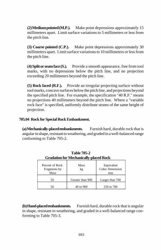
Section 705
693
(2) Medium pointed (M.P.). Make point depressions approximately 15millimeters apart. Limit surface variations to 5 millimeters or less fromthe pitch line.
(3) Coarse pointed (C.P.). Make point depressions approximately 30millimeters apart. Limit surface variations to 10 millimeters or less fromthe pitch line.
(4) Split or seam face (S.). Provide a smooth appearance, free from toolmarks, with no depressions below the pitch line, and no projectionexceeding 20 millimeters beyond the pitch line.
(5) Rock faced (R.F.). Provide an irregular projecting surface withouttool marks, concave surfaces below the pitch line, and projections beyondthe specified pitch line. For example, the specification "40 R.F." meansno projections 40 millimeters beyond the pitch line. Where a "variablerock face" is specified, uniformly distribute stones of the same height ofprojection.
705.04 Rock for Special Rock Embankment.
(a) Mechanically-placed embankments. Furnish hard, durable rock that isangular in shape, resistant to weathering, and graded in a well-balanced rangeconforming to Table 705-2.
Table 705-2Gradation for Mechanically-placed Rock
Percent of Rock Mass Equivalent Fragments by kg Cubic Dimension
Mass mm
50 Greater than 900 Larger than 700
50 40 to 900 250 to 700
(b) Hand-placed embankments. Furnish hard, durable rock that is angularin shape, resistant to weathering, and graded in a well-balanced range con-forming to Table 705-3.
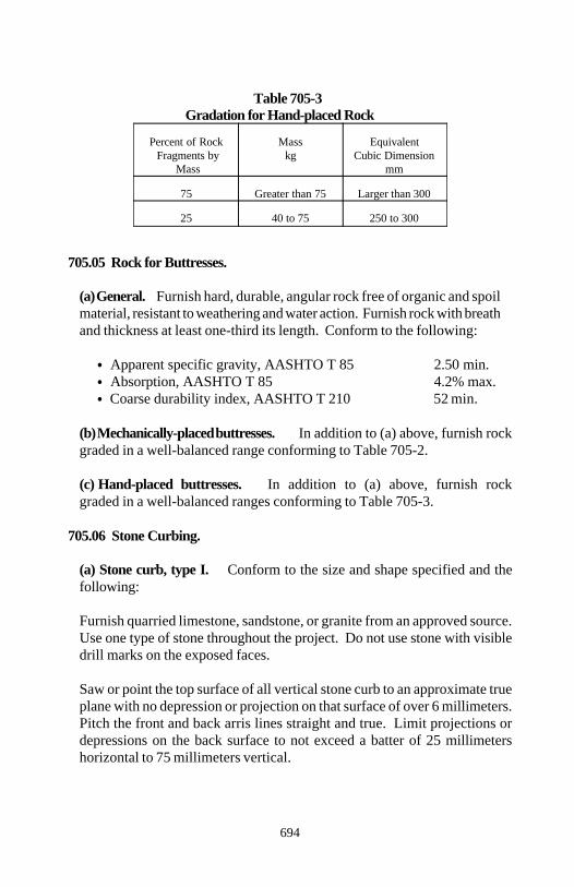
Section 705
694
Table 705-3Gradation for Hand-placed Rock
Percent of Rock Mass Equivalent Fragments by kg Cubic Dimension
Mass mm
75 Greater than 75 Larger than 300
25 40 to 75 250 to 300
705.05 Rock for Buttresses.
(a) General. Furnish hard, durable, angular rock free of organic and spoilmaterial, resistant to weathering and water action. Furnish rock with breathand thickness at least one-third its length. Conform to the following:
Apparent specific gravity, AASHTO T 85 2.50 min. Absorption, AASHTO T 85 4.2% max. Coarse durability index, AASHTO T 210 52 min.
(b) Mechanically-placed buttresses. In addition to (a) above, furnish rockgraded in a well-balanced range conforming to Table 705-2.
(c) Hand-placed buttresses. In addition to (a) above, furnish rockgraded in a well-balanced ranges conforming to Table 705-3.
705.06 Stone Curbing.
(a) Stone curb, type I. Conform to the size and shape specified and thefollowing:
Furnish quarried limestone, sandstone, or granite from an approved source.Use one type of stone throughout the project. Do not use stone with visibledrill marks on the exposed faces.
Saw or point the top surface of all vertical stone curb to an approximate trueplane with no depression or projection on that surface of over 6 millimeters.Pitch the front and back arris lines straight and true. Limit projections ordepressions on the back surface to not exceed a batter of 25 millimetershorizontal to 75 millimeters vertical.
Section 705
695
Saw, point, or smooth quarry split the front exposed face of the vertical stonecurb and form to an approximately true plane. Limit projections ordepressions on the remaining face distance to 25 millimeters or less from theplane of the exposed face.
Square the ends of vertical stone curb with the top back and face and finishso when the sections are placed end to end, no space more than 13millimeters shall show in the joint for the full width of the top surface and forthe entire exposed front face. The remainder of the end may break back nomore than 100 millimeters from the plane of the joint. Cut the joints ofcircular or curved stone curb on radial lines.
The minimum length of any segment of vertical stone curb is 1.2 meters.However the length may vary where a depressed or modified section of curbis required for driveways, crossings, closures, etc.
(b) Stone curb, type II. Slope stone curb shall conform to the requirementsfor type I stone curb except as follows:
The maximum allowable projection or depression on a horizontal top surfaceis limited to 13 millimeters. On other exposed faces, the maximumallowable projection or depression is limited to 25 millimeters.
For unexposed surfaces, the maximum allowable projection or depressionfrom a true plane on a 0.5 meter length shall be 75 millimeters.
The maximum allowable space showing on exposed faces between adjacentsegments of slope stone curb is 19 millimeters. The minimum length of anysegment of slope stone curb is 0.5 meter.
696
Section 706.) CONCRETE AND PLASTIC PIPE
706.01 Non-Reinforced Concrete Pipe. Conform to AASHTO M 86M forthe diameters and strength classes specified.
706.02 Reinforced Concrete Pipe. Conform to AASHTO M 170M for thediameters and strength classes specified. For precast reinforced concrete endsections, conform to cited specifications to the extent they apply.
706.03 Perforated Concrete Pipe. Conform to AASHTO M 175M type 1or 2 and AASHTO M 86M for the diameters and strength classes speci-fied.
706.04 Reinforced Arch-Shaped Concrete Pipe. Conform to AASHTO M206M for the diameters and strength classes specified.
706.05 Reinforced Elliptically-Shaped Concrete Pipe. Conform toAASHTO M 207M for the diameters, placement design (horizontal orvertical), and strength classes specified.
706.06 Reinforced D-Load Concrete Pipe. Conform to AASHTO M 242Mfor the diameters specified.
706.07 Precast Reinforced Concrete Box Sections. Conform to AASH-TO M 259M or M 273M, as applicable, for dimensions and loading conditionsspecified.
706.08 Plastic Pipe. Furnish perforated and nonperforated plastic pipe con-forming to the following for the sizes and types specified. For watertightjoints, conform to ASTM D 3212.
(a) Smooth wall polyethylene pipe. Furnish 300 to 1050-millimeterdiameter pipe conforming to ASTM F 714 and minimum cell class, ASTMD 3350, 335434C.
(b) Corrugated polyethylene pipe. Furnish 300 to 900-millimeter diameterpipe conforming to AASHTO M 294 and minimum cell class, ASTM D3350, 315412C or 324420C. For sanitary sewer applications, furnishAASHTO M 294 type S pipe with watertight joints.
Section 706
697
(c) Profile wall (ribbed) polyethylene pipe. Furnish 450 to 1200-milli-meter diameter pipe conforming to ASTM F 894 and minimum cell class,ASTM D 3350, 334433C or 335434C.
(d) Corrugated polyethylene drainage tubing. Furnish 75 to 250-milli-meter diameter tubing conforming to AASHTO M 252.
(e) Smooth wall polyvinyl chloride pipe. Furnish 100 to 375-millimeterdiameter pipe conforming to AASHTO M 278 and minimum cell class,ASTM D 1784, 12454C or 12364C. For sanitary sewer applications,conform to ASTM D 3034.
(f) Profile wall (ribbed) polyvinyl chloride pipe. Furnish 100 to 1200-millimeter diameter pipe conforming to AASHTO M 304 and minimum cellclass, ASTM D 1784, 12454C or 12364C. For sanitary sewer applications,conform to ASTM F 794 or F 949.
(g) Acrylonitrile-butadiene-styrene (ABS) pipe. Conform to AASHTO M264. For perforations, conform to AASHTO M 278.
698
Section 707.) METAL PIPE
707.01 Ductile Iron Culvert Pipe. Conform to ASTM A 716 for the sizesspecified.
707.02 Metallic-Coated Corrugated Steel Pipe. Furnish pipe, special sec-tions (such as elbows, branch connections, and prefabricated flared endsections), and coupling bands conforming to AASHTO M 36M and eitherAASHTO M 218, M 274, or M 289 for the dimensions and thicknessesspecified.
Fabricate underdrain pipe from steel sheets with a minimum thickness of 1.32millimeters. Use any class of perforation specified in AASHTO M 36M.
707.03 Aluminum-Alloy Corrugated Pipe. Furnish pipe, special sections(such as elbows, branch connections, and prefabricated flared end sections),and coupling bands conforming to AASHTO M 196M for the dimensions andthicknesses specified.
Fabricate underdrain pipe from aluminum sheets with a minimum thickness of1.22 millimeters. Use any class of perforation.
707.04 Asphalt-Coated Pipe. Furnish pipe, special sections (such as elbows,branch connections, and prefabricated flared end sections), and coupling bandsconforming to Subsections 707.02, 707.03, 707.08, 707.09, and 707.13 asapplicable for the kinds of pipes to be coated.
Coat the pipe with asphalt material conforming to AASHTO M 190 for thetype of coating specified. Coat special sections (such as elbows, branchconnections, and end sections) and coupling bands according to AASHTO M190. Coat flared end sections with an asphalt coating conforming to AASHTOM 190 type A or a field applied asphalt mastic coating conforming toAASHTO M 243.
707.05 Steel Structural Plate Structures. Furnish structures and assemblyfasteners for connecting plates conforming to AASHTO M 167M for the sizesand types specified.
Section 707
699
707.06 Aluminum-Alloy Structural Plate Structures. Furnish structuresand assembly fasteners for connecting plates conforming to AASHTO M 219Mfor the sizes and types specified.
707.07 Asphalt-Coated Structural Plate Structures. Furnish structuresconforming to either Subsection 707.05 or 707.06 as applicable. Coat with anasphalt coating conforming to AASHTO M 190 type A or a field appliedasphalt mastic coating conforming to AASHTO M 243.
If the asphalt coating is applied to the plates before field erection, identify eachplate's nominal metal thickness by painting the data on the inside surface of theplates after coating. Other methods of plate identification may be used ifapproved.
707.08 Polymer-Coated Steel Pipe. Furnish pipe, special sections (such aselbows and branch connections), and coupling bands conforming to AASHTOM 245M and M 246M. Furnish pipe with a grade 250/250 polymer coating.
707.09 Fiber-Bonded Asphalt Coated Steel Pipe. Furnish pipe, specialsections (such as elbows, branch connections, and prefabricated flared endsections), and coupling bands conforming to Subsection 707.02 except use azinc metallic coating impregnated with an aramid fiber composite conformingto ASTM A 885.
After fabrication, coat the pipe sections with asphalt material according toAASHTO M 190 for the type of coating specified.
Coat coupling bands with a asphalt material according to AASHTO M 190type A. Coupling bands do not require fiber bonding.
707.10 Slotted Drain Pipe. Furnish pipe conforming to AASHTO M 36Mand either AASHTO M 218, 274, or M 289 for the dimensions and thicknessesspecified. Fabricate the pipe with either angle slots or grate slots and as shownon the plans.
Furnish grate assemblies for the grate slot drain conforming to ASTM A 570Mgrade 36. Galvanize slot angles and grate slot assemblies according toSubsection 725.12.
Section 707
700
707.11 Metallic-Coated Spiral Rib Pipe. Furnish pipe, special sections(such as elbows and branch connections), and coupling bands conforming toAASHTO M 36M type IR and IIR and AASHTO M 218, AASHTO M 274,or AASHTO M 289 for the dimensions and thicknesses specified.
707.12 Aluminum-Alloy Spiral Rib Pipe. Furnish pipe, special sections(such as elbows and branch connections), and coupling bands conforming toAASHTO M 196M type IR and IIR for the dimensions and thicknessesspecified.
707.13 Concrete-Lined Corrugated Steel Pipe. Furnish pipe, special sec-tions (such as elbows and branch connections), and coupling bands conformingto Subsection 707.02 for the dimensions and thicknesses specified. Fully linethe pipe and special sections with concrete according to ASTM A 849 class C.
707.14 Invert-Paved Corrugated Steel Pipe. Furnish pipe, special sections(such as elbows and branch connections), and coupling bands conforming toSubsection 707.02 for the dimensions and thicknesses specified. Pave theinvert of the pipe and special sections with concrete or asphalt materialaccording to ASTM A 849 class C or B, as specified.
701
Section 708.) PAINT
708.01 General. Furnish a contrasting color for each coat of paint. For thefinish coat color, conform to Federal Standard 595 B. If requested, providecolor chips from the paint supplier.
(a) Packaging. Furnish paint in strong, substantial containers, plainlymarked with the following:
(1) Trade name or trade mark(2) Paint type, color, formulation, lot number, and date of manufacture(3) Net mass(4) Volume including the percent of solids and the percent of volatileorganic compound (VOC)(5) Storage requirements(6) Mixing instructions and equipment cleanup instructions(7) Name and address of the manufacturer
(b) Volatile organic compound (VOC) content. Conform to the followingVOC limits for both shop and field painting:
(1) Clear (unpigmented) coatings 520 g/L max.(2) Other coatings 350 g/L max.
(c) Lead content. max. 0.06% by mass in the dried film
(d) Other properties. Furnish paint that:
(1) Does not show excessive settling in a freshly-opened full can(2) Easily redisperses with a paddle to a smooth, homogeneous state freeof curdling, livering, caking, color separation, lumps, and skins (3) Does not skin within 48 hours in a ¾ filled, closed container(4) Brushes on easily(5) Possess good leveling properties(6) Shows no running or sagging tendencies when applied to smooth steelvertical surfaces(7) Dries to a smooth uniform finish, free from roughness, grit, un-evenness and other surface imperfections(8) Shows no streaking or separation when flowed on clean glass
Section 708
702
(9) Shows no thickening, curdling, gelling, or hard caking after 6 monthsof storage in a full, tightly-covered container at a temperature of 20 C
708.02 Paint for Timber Structures.
(a) Primer. Conform to FSS TT-P-25, TT-P-96D, or TT-P-001984.
(b) Paint. Conform to FSS TT-P-102 class A, TT-P-96D, TT-P-102F, orTT-P-19D.
708.03 Paint for Concrete and Masonry Block Structures. Conform toFSS TT-P-19. Color tint with universal or all purpose concentrates.
708.04 Paint for Steel Structures. Conform to the following:
(a) Inorganic zinc primer. AASHTO M 300 type II
(b) Vinyl wash primer. MIL-P-15328 or SSPC no. 27
(c) Aliphatic urethane coating. USPS-C-644 type I
(d) Acrylic latex coating. SSPC no. 24
(e) Epoxy coating. MIL-P-24441 or SSPC no. 22
708.05 Penetrating Stain. Conform to the following:
(a) Weatherometer on base 1000 hmaterial, ASTM G 23(b) Acrylic dispersion 73.4% of nonvolatile vehicle(c) Viscosity 58±2 Krebs units(d) Solids volatile content 40.3
Store stain according to the manufacturer's recommendations.
703
Section 709.) REINFORCING STEEL AND WIRE ROPE
709.01 Reinforcing Steel.
(a) General. Furnish the following information with each shipment of steelto the project:
(1) Name and location of the steel rolling mill(2) Manufacturing process(3) Heat number(s)(4) Size(s)(5) Specifications(6) Copies of mill test analyses for chemical and physical tests(7) Consignee and destination of shipment
(b) Reinforcing bars. Furnish deformed, grade 400 bars conforming to A-ASHTO M 31M, M 42M, or M 53M.
(c) Epoxy coated reinforcing bars. Conform to AASHTO M 284M.
Inspect the reinforcing bars after the near white blast cleaning. Reject allbars with steel slivers or scabs. Selective sorting and rejection at the fab-ricator's shop may avoid unnecessary delays and subsequent rejection of barsduring the precoating inspection at the coating applicator's shop.
Coat epoxy coated reinforcing steel in a plant certified by CRSI as a fusionbonded epoxy applicator.
(d) Tie bars. Furnish deformed, grade 400 bars conforming to AASHTO M- 31M or M 42M, except do not use AASHTO M 42M steel for tie bars bentand restraightened during construction.
(e) Hook bolts. Furnish plain, grade 400 bars conforming to AASHTO M- 31M or M 42M with M14 rolled threads or M16 cut threads. Furnish athreaded sleeve nut capable of sustaining a minimum axial load of 67 kilone-wtons.
Section 709
704
(f) Dowel bars. Conform to AASHTO M 254 type A or B. Use plain roundbars, free from burring or other deformation restricting free movement in theconcrete. Paint half the length of each dowel bar with one coat of tar paint.When the paint dries and immediately before placing the dowels, lubricatethe painted end to prevent concrete from bonding to the painted end.
For expansion joints, furnish a dowel cap that snugly covers 50±5 millime-ters of the dowel, has a closed end, and has a suitable stop to hold the closedend 25 millimeters from the end of the dowel bar.
Lubricants for type B dowels may be rapid-curing cut-back asphalt, mediumsetting emulsified asphalt, or a flaked graphite and vehicle. Lubricants arenot required for type A coated dowel bars.
Furnish dowel assemblies that hold dowel bars within 6-millimeter tolerancevertically and horizontally during concrete placement and permit unrestrictedmovement of the pavement slab.
Use wire conforming to AASHTO M 32M for dowel assemblies. Coat dowelassemblies with the same material as the dowel bar. Recoat or repair dam-aged coatings equivalent to the manufacturer's original coating.
(g) Deformed steel wire. Conform to AASHTO M 225M.
(h) Welded steel wire fabric. Conform to AASHTO M 55M.
(i) Cold-drawn steel wire. Conform to AASHTO M 32M.
(j) Welded deformed steel wire fabric. Conform to AASHTO M 221M.
(k) Fabricated deformed steel bar or rod mats. Conform to AASHTO M54M.
(l) Low alloy steel deformed bars. Conform to ASTM A 706M.
709.02 Wire Rope or Wire Cable. Conform to AASHTO M 30 for the sizeand strength class specified.
Section 709
705
709.03 Prestressing Steel. Fabricate from one of the following:
• Stress-relieved wire strand, AASHTO M 204M type BA or WA• Stress-relieved seven-wire strand, AASHTO M 203M grade 270• High-strength steel bars, AASHTO M 275M type II
Protect all prestressing steel against physical damage, rust, or corrosion at alltimes. Do not use damaged prestressing steel.
Package prestressing steel to protect it from physical damage and corrosionduring shipping and storage. Place a corrosion inhibitor in the package. Usea corrosion inhibitor that will have no deleterious effect on the steel, concrete,or bond strength of steel to concrete. Immediately replace or restore damagedpackaging.
Mark the shipping package with a statement that the package contains high-strength prestressing steel and a warning to use care in handling. Identify thetype, kind, and amount of corrosion inhibitor used, including the date whenplaced, safety regulations, and instructions for use. Assign a lot number andtag, for identification purposes, to all wire, strand, anchorage assemblies, orbars shipped to the site.
Submit representative samples from prestressed members fabricated off site.In the case of wire or strand, take the sample from the same master roll.
(a) Pretensioning method. Furnish a sample at least 2 meters long of eachstrand size from each coil.
(b) Post-tensioning method. Furnish samples of the following lengths.
(1) For wires requiring a head, 5 meters.
(2) For wires not requiring a head, sufficient length to make up oneparallel-lay cable 1.5 meters long consisting of the same number of wiresas the cable to be furnished.
(3) For strands furnished with fittings, 1.5 meters between near ends offittings.
(4) For bars to be furnished with threaded ends and nuts, 1.5 meters be-tween threads at ends.
706
Section 710.) FENCE AND GUARDRAIL
710.01 Barbed Wire. Furnish galvanized wire conforming to AASHTO M280 or aluminum coated wire conforming to AASHTO M 305 type I.
710.02 Woven Wire. Furnish galvanized fabric conforming to AASHTO M279 or aluminum coated fabric conforming to ASTM A 584.
710.03 Chain Link Fence. Furnish fabric, posts, rails, ties, bands, bars, rods,and other fittings and hardware conforming to AASHTO M 181.
Furnish 4.5-millimeter coiled spring steel tension wire conforming to ASTMA 641M hard temper with a class 3 galvanized coating or an aluminizedcoating having a minimum coating mass of 120 grams per square meter ofaluminum. Use the same coating on the tension wire as used on the rest of thechain link fence.
710.04 Fence Posts.
(a) Wood. Conform to AASHTO M 168.
Peel all bark, except for red cedar posts and bracing which do not requirepeeling. Trim all knots flush with the surface and season the wood.
For dimension lumber for fences or gates, use timber that is sound, straight,and reasonably free from knots, splits, and shakes. Provide S4S finish.
(b) Concrete. Conform to Section 601.
(c) Steel. For line fence posts, conform to AASHTO M 281. For chain linkfence, conform to AASHTO M 181.
710.05 Fence Gates. For frame gates used with chain link fences, conformto AASHTO M 181. Use the same chain link fabric in the gate and the fence.
Section 710
707
710.06 Metal Beam Rail.
(a) Galvanized steel rail. Furnish W-beam or thrie beam rail elements fabri-cated from corrugated sheet steel conforming to AASHTO M 180 for thedesignated shape, class, type, and mass of coating specified.
(b) Corrosion resistant steel rail. Furnish W-beam or thrie beam railelements and associated weathering steel hardware conforming to the follow-ing:
(1) Shapes and plates AASHTO M 222M(2) Rail elements ASTM A 606 type 4(3) Fasteners AASHTO M 164M type 3
710.07 Box Beam Rail. Furnish steel box beam rail elements conforming tothe AASHTO-AGC-ARTBA A Guide to Standardized Highway BarrierHardware, 1995 edition.
710.08 Steel-Backed Timber Rail. Furnish timber conforming to AASHTOM 168. Fabricate the 150 by 250-millimeter timber rail and the 100 by 225-millimeter blockouts from dry, well seasoned, and dressed rough sawn Douglasfir, southern pine, or other species having a stress grade of at least 10megapascals.
Treat the timber rail and blockout elements with CCA, ACZA, or ACApreservative treatment conforming to AWPA C14 except the minimumretention shall be 9.6 kilograms per cubic meter.
Fabricate the steel backing elements from 9.5-millimeter structural steelconforming to AASHTO M 222M. For fastener hardware, conform toAASHTO M 222M.
710.09 Guardrail Posts.
(a) Wood posts. Do not use a wood guardrail post that has a through check,shake, or end split in the same plane as, or a plane parallel to the bolt holeand extending from the top of the post to within 75 millimeters of the bolthole.
(b) Box beam posts. Conform to the AASHTO-AGC-ARTBA A Guide toStandardized Highway Barrier Hardware, 1995 edition.
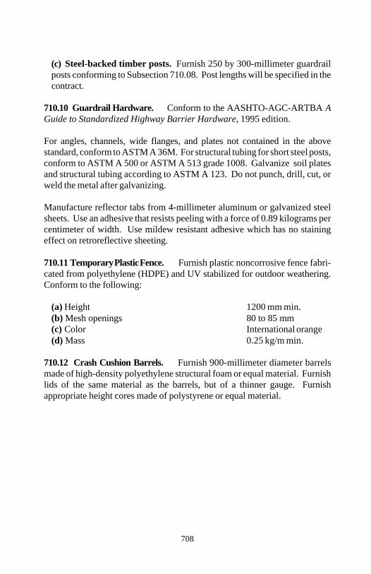
Section 710
708
(c) Steel-backed timber posts. Furnish 250 by 300-millimeter guardrailposts conforming to Subsection 710.08. Post lengths will be specified in thecontract.
710.10 Guardrail Hardware. Conform to the AASHTO-AGC-ARTBA AGuide to Standardized Highway Barrier Hardware, 1995 edition.
For angles, channels, wide flanges, and plates not contained in the abovestandard, conform to ASTM A 36M. For structural tubing for short steel posts,conform to ASTM A 500 or ASTM A 513 grade 1008. Galvanize soil platesand structural tubing according to ASTM A 123. Do not punch, drill, cut, orweld the metal after galvanizing.
Manufacture reflector tabs from 4-millimeter aluminum or galvanized steelsheets. Use an adhesive that resists peeling with a force of 0.89 kilograms percentimeter of width. Use mildew resistant adhesive which has no stainingeffect on retroreflective sheeting.
710.11 Temporary Plastic Fence. Furnish plastic noncorrosive fence fabri-cated from polyethylene (HDPE) and UV stabilized for outdoor weathering.Conform to the following:
(a) Height 1200 mm min.(b) Mesh openings 80 to 85 mm(c) Color International orange(d) Mass 0.25 kg/m min.
710.12 Crash Cushion Barrels. Furnish 900-millimeter diameter barrelsmade of high-density polyethylene structural foam or equal material. Furnishlids of the same material as the barrels, but of a thinner gauge. Furnishappropriate height cores made of polystyrene or equal material.
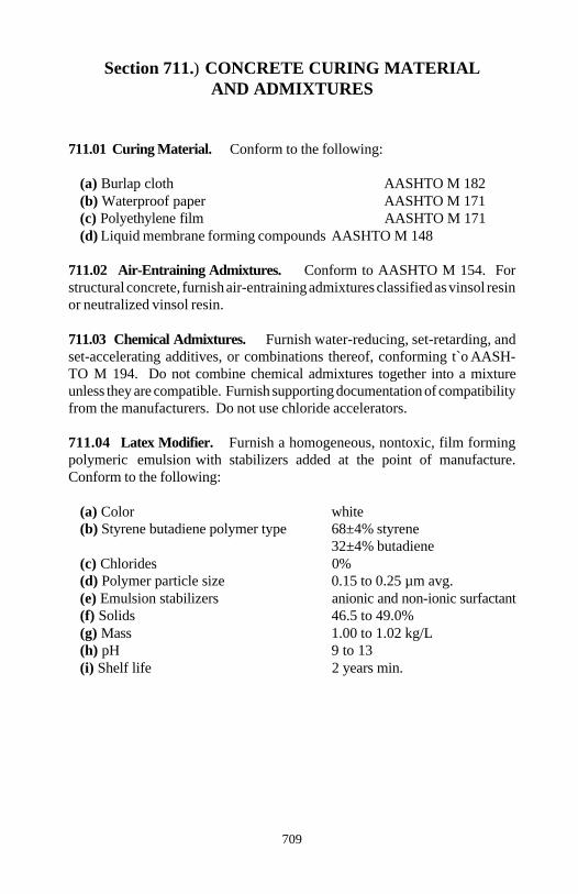
709
Section 711.) CONCRETE CURING MATERIALAND ADMIXTURES
711.01 Curing Material. Conform to the following:
(a) Burlap cloth AASHTO M 182(b) Waterproof paper AASHTO M 171(c) Polyethylene film AASHTO M 171(d) Liquid membrane forming compounds AASHTO M 148
711.02 Air-Entraining Admixtures. Conform to AASHTO M 154. Forstructural concrete, furnish air-entraining admixtures classified as vinsol resinor neutralized vinsol resin.
711.03 Chemical Admixtures. Furnish water-reducing, set-retarding, andset-accelerating additives, or combinations thereof, conforming t`o AASH-TO M 194. Do not combine chemical admixtures together into a mixtureunless they are compatible. Furnish supporting documentation of compatibilityfrom the manufacturers. Do not use chloride accelerators.
711.04 Latex Modifier. Furnish a homogeneous, nontoxic, film formingpolymeric emulsion with stabilizers added at the point of manufacture.Conform to the following:
(a) Color white(b) Styrene butadiene polymer type 68±4% styrene
32±4% butadiene(c) Chlorides 0%(d) Polymer particle size 0.15 to 0.25 µm avg.(e) Emulsion stabilizers anionic and non-ionic surfactant(f) Solids 46.5 to 49.0%(g) Mass 1.00 to 1.02 kg/L(h) pH 9 to 13(i) Shelf life 2 years min.
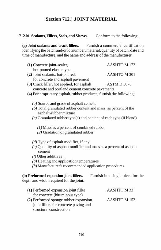
710
Section 712.) JOINT MATERIAL
712.01 Sealants, Fillers, Seals, and Sleeves. Conform to the following:
(a) Joint sealants and crack fillers. Furnish a commercial certificationidentifying the batch and/or lot number, material, quantity of batch, date andtime of manufacture, and the name and address of the manufacturer.
(1) Concrete joint-sealer, AASHTO M 173 hot-poured elastic type
(2) Joint sealants, hot-poured, AASHTO M 301 for concrete and asphalt pavement
(3) Crack filler, hot applied, for asphalt ASTM D 5078 concrete and portland cement concrete pavements
(4) For proprietary asphalt-rubber products, furnish the following:
(a) Source and grade of asphalt cement(b) Total granulated rubber content and mass, as percent of the
asphalt-rubber mixture(c) Granulated rubber type(s) and content of each type (if blend).
(1) Mass as a percent of combined rubber(2) Gradation of granulated rubber
(d) Type of asphalt modifier, if any(e) Quantity of asphalt modifier and mass as a percent of asphalt
cement(f) Other additives(g) Heating and application temperatures(h) Manufacturer's recommended application procedures
(b) Preformed expansion joint fillers. Furnish in a single piece for thedepth and width required for the joint.
(1) Performed expansion joint filler AASHTO M 33 for concrete (bituminous type)
(2) Performed sponge rubber expansion AASHTO M 153 joint fillers for concrete paving and structural construction
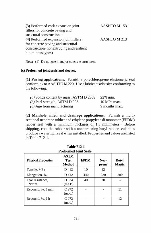
Section 712
711
(3) Performed cork expansion joint AASHTO M 153fillers for concrete paving and structural construction(1)
(4) Performed expansion joint fillers AASHTO M 213for concrete paving and structural construction (nonextruding and resilient bituminous types)
Note: (1) Do not use in major concrete structures.
(c) Preformed joint seals and sleeves.
(1) Paving applications. Furnish a polychloroprene elastomeric sealconforming to AASHTO M 220. Use a lubricant adhesive conforming tothe following:
(a) Solids content by mass, ASTM D 2369 22% min.(b) Peel strength, ASTM D 903 10 MPa max.(c) Age from manufacturing 9 months max.
(2) Manhole, inlet, and drainage applications. Furnish a multi-sectional neoprene rubber and ethylene propylene di monomer (EPDM)rubber seal with a minimum thickness of 1.5 millimeters. Beforeshipping, coat the rubber with a nonhardening butyl rubber sealant toproduce a watertight seal when installed. Properties and values are listedin Table 712-1.
Table 712-1Preformed Joint Seals
Physical Properties Test EPDM Neo- ButylASTM
Method prene MasticTensile, MPa D 412 10 12 -Elongation, % D 412 440 230 280Tear resistance, D 624 40 20 - N/mm (die B)Rebound, %, 5 min C 972 - - 11
(mod.)Rebound, %, 2 h C 972 - - 12
(mod.)
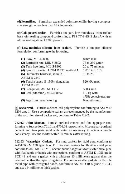
Section 712
712
(d) Foam filler. Furnish an expanded polystyrene filler having a compres-sive strength of not less than 70 kilopascals.
(e) Cold-poured sealer. Furnish a one-part, low-modulus silicone rubberbase joint sealing compound conforming to FSS TT-S-1543 class A with anultimate elongation of 1200 percent.
(f) Low-modulus silicone joint sealant. Furnish a one-part siliconeformulation conforming to the following.
(1) Flow, MIL S-8802 8 mm max.(2) Extrusion rate, MIL S-8802 75 to 250 g/min(3) Tack free time, MIL S-8802 20 to 75 minutes(4) Specific gravity, ASTM D 792, method A 1.010 to 1.515(5) Durometer hardness, shore A, 10 to 25ASTM D 2240(6) Tensile stress @ 150% elongation, 520 kPa max.ASTM D 412(7) Elongation, ASTM D 412 500% min.(8) Peel (adhesion), MIL S-8802 9 kg with
75% cohesive failure(9) Age from manufacturing 6 months max.
(g) Backer rod. Furnish a closed-cell polyethylene conforming to ASTM D3204 type 1. Use a compatible sealant as recommended by the manufacturerof the rod. For size of backer rod, conform to Table 712-2.
712.02 Joint Mortar. Furnish portland cement and fine aggregate con-forming to Subsections 701.01 and 703.01 respectively. Mix one part portlandcement and two parts sand with water as necessary to obtain a usableconsistency. Use the mortar within 30 minutes after mixing.
712.03 Watertight Gaskets. For ring gaskets for rigid pipe, conform toAASHTO M 198 type A or B. For ring gaskets for flexible metal pipe,conform to ASTM C 361M. For continuous flat gaskets for flexible metal pipewith flat bands or bands with projections, conform to ASTM D 1056 gradeSCE 41 and use a gasket with a thickness 13 millimeters greater than thenominal depth of the pipe corrugations. For continuous flat gaskets for flexiblemetal pipe with corrugated bands, conform to ASTM D 1056 grade SCE 43and use a 9-millimeter thick gasket.
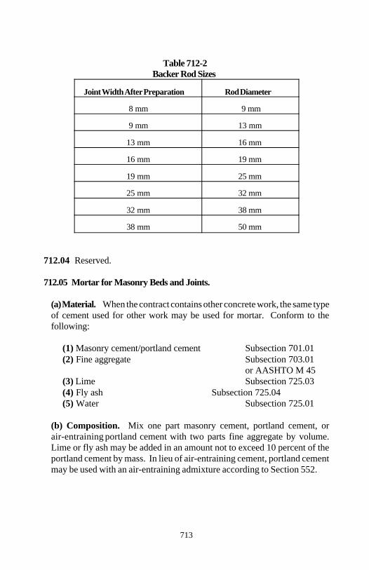
Section 712
713
Table 712-2 Backer Rod Sizes
Joint Width After Preparation Rod Diameter
8 mm 9 mm
9 mm 13 mm
13 mm 16 mm
16 mm 19 mm
19 mm 25 mm
25 mm 32 mm
32 mm 38 mm
38 mm 50 mm
712.04 Reserved.
712.05 Mortar for Masonry Beds and Joints.
(a) Material. When the contract contains other concrete work, the same typeof cement used for other work may be used for mortar. Conform to thefollowing:
(1) Masonry cement/portland cement Subsection 701.01(2) Fine aggregate Subsection 703.01
or AASHTO M 45(3) Lime Subsection 725.03(4) Fly ash Subsection 725.04(5) Water Subsection 725.01
(b) Composition. Mix one part masonry cement, portland cement, orair-entraining portland cement with two parts fine aggregate by volume.Lime or fly ash may be added in an amount not to exceed 10 percent of theportland cement by mass. In lieu of air-entraining cement, portland cementmay be used with an air-entraining admixture according to Section 552.
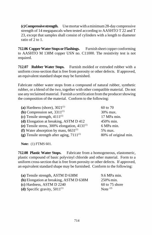
Section 712
714
(c) Compressive strength. Use mortar with a minimum 28-day compressivestrength of 14 megapascals when tested according to AASHTO T 22 and T23, except that samples shall consist of cylinders with a length to diameterratio of 2 to 1.
712.06 Copper Water Stops or Flashings. Furnish sheet copper conformingto AASHTO M 138M copper USN no. C11000. The resistivity test is notrequired.
712.07 Rubber Water Stops. Furnish molded or extruded rubber with auniform cross-section that is free from porosity or other defects. If approved,an equivalent standard shape may be furnished.
Fabricate rubber water stops from a compound of natural rubber, syntheticrubber, or a blend of the two, together with other compatible material. Do notuse any reclaimed material. Furnish a certification from the producer showingthe composition of the material. Conform to the following:
(a) Hardness (shore), 3021 60 to 70(1)
(b) Compression set, 3311 30% max.(1)
(c) Tensile strength, 4111 17 MPa min.(1)
(d) Elongation at breaking, ASTM D 412 450% min.(e) Tensile stress, 300% elongation, 4131 6 MPa min.(1)
(f) Water absorption by mass, 6631 5% max.(1)
(g) Tensile strength after aging, 7111 80% of original min.(1)
Note: (1) FTMS 601.
712.08 Plastic Water Stops. Fabricate from a homogeneous, elastomeric,plastic compound of basic polyvinyl chloride and other material. Form to auniform cross-section that is free from porosity or other defects. If approved,an equivalent standard shape may be furnished. Conform to the following:
(a) Tensile strength, ASTM D 638M 9.6 MPa min.(b) Elongation at breaking, ASTM D 638M 250% min.(c) Hardness, ASTM D 2240 60 to 75 shore(d) Specific gravity, 5011 Note (1) (2)
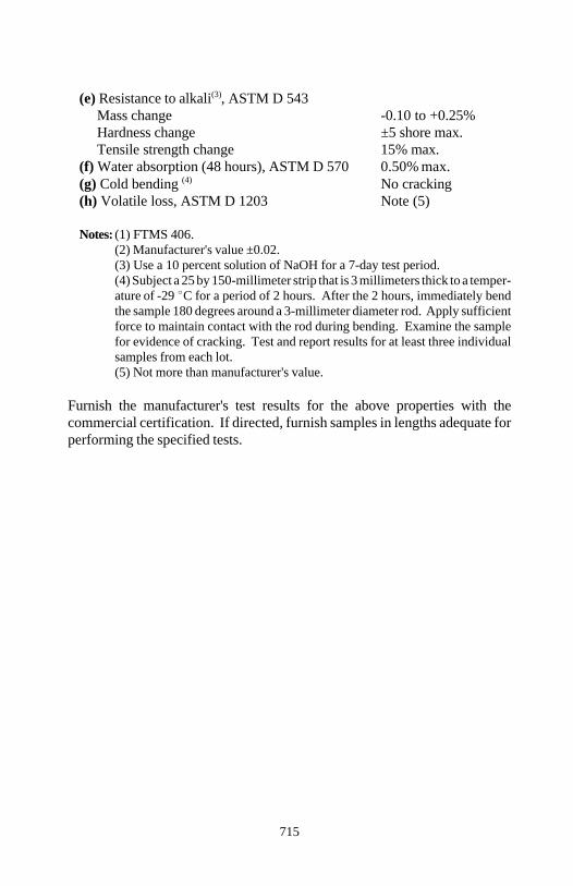
Section 712
715
(e) Resistance to alkali , ASTM D 543(3)
Mass change -0.10 to +0.25%Hardness change ±5 shore max.Tensile strength change 15% max.
(f) Water absorption (48 hours), ASTM D 570 0.50% max.(g) Cold bending No cracking(4)
(h) Volatile loss, ASTM D 1203 Note (5)
Notes: (1) FTMS 406.(2) Manufacturer's value ±0.02.(3) Use a 10 percent solution of NaOH for a 7-day test period.(4) Subject a 25 by 150-millimeter strip that is 3 millimeters thick to a temper-ature of -29 C for a period of 2 hours. After the 2 hours, immediately bendthe sample 180 degrees around a 3-millimeter diameter rod. Apply sufficientforce to maintain contact with the rod during bending. Examine the samplefor evidence of cracking. Test and report results for at least three individualsamples from each lot.(5) Not more than manufacturer's value.
Furnish the manufacturer's test results for the above properties with thecommercial certification. If directed, furnish samples in lengths adequate forperforming the specified tests.
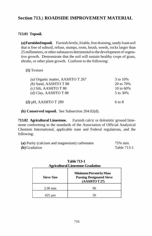
716
Section 713.) ROADSIDE IMPROVEMENT MATERIAL
713.01 Topsoil.
(a) Furnished topsoil. Furnish fertile, friable, free draining, sandy loam soilthat is free of subsoil, refuse, stumps, roots, brush, weeds, rocks larger than25 millimeters, or other substances detrimental to the development of vegeta-tive growth. Demonstrate that the soil will sustain healthy crops of grass,shrubs, or other plant growth. Conform to the following:
(1) Texture
(a) Organic matter, AASHTO T 267 3 to 10%(b) Sand, AASHTO T 88 20 to 70%(c) Silt, AASHTO T 88 10 to 60%(d) Clay, AASHTO T 88 5 to 30%
(2) pH, AASHTO T 289 6 to 8
(b) Conserved topsoil. See Subsection 204.02(d).
713.02 Agricultural Limestone. Furnish calcic or dolomitic ground lime-stone conforming to the standards of the Association of Official AnalyticalChemists International, applicable state and Federal regulations, and thefollowing:
(a) Purity (calcium and magnesium) carbonates 75% min.(b) Gradation Table 713-1
Table 713-1Agricultural Limestone Gradation
Sieve Size Passing Designated SieveMinimum Percent by Mass
(AASHTO T 27)
2.00 mm 90
425 µm 50
Section 713
717
Granulated slag or other approved natural sources of lime may be usedprovided the application rate is adjusted to equal the total neutralizing powerof the specified ground limestone.
713.03 Fertilizer. Furnish standard commercial grade dry formulatedfertilizer conforming to the standards of the Association of Official AnalyticalChemists International, applicable state and Federal regulations, and requiredminimum percentages of available nutrients.
Supply the fertilizer in new, clean, sealed, and properly labeled containers withname, mass, and guaranteed analysis of contents clearly marked.
Liquid fertilizer containing the minimum percentage of available nutrients maybe used.
713.04 Seed. Conform to FSS JJJ-S-181. Do not use wet, moldy, orotherwise contaminated or damaged seed. Furnish each seed type in separatesealed container. Clearly label each container with the following:
(a) Name and type of seed(b) Lot number(c) Net mass(d) Percent of purity, germination, and hard seed(e) Percent of maximum weed seed content
Inoculate legume seed with approved cultures according to the manufacturer'sinstructions.
713.05 Mulch.
(a) Straw. Furnish straw from oats, wheat, rye, or other grain crops that isfree from weeds, mold, or other objectionable material. Furnish straw in anair-dry condition suitable for placing with mulch blower equipment.
(b) Hay. Furnish hay from herbaceous mowing, free from weeds, mold, orother objectionable material. Furnish hay in an air-dry condition suitable forplacing with mulch blower equipment.
Section 713
718
(c) Wood fiber. Furnish processed wood fiber from wood chips that is asfollows:
(1) Colored with a green dye noninjurious to plant growth(2) Readily dispersible in water(3) Nontoxic to seed or other plant material(4) Free of growth or germination inhibiting substances(5) Free of weed seed(6) Air dried to an equilibrium moisture content of 12±3 percent(7) Packaged in new labeled containers(8) Packaged in a condition appropriate for mixing in a homogeneousslurry suitable for application with power spray equipment
(d) Grass straw cellulose fiber. Furnish processed grass straw fiber that isas follows:
(1) Colored with a green dye noninjurious to plant growth(2) Readily dispersible in water(3) Nontoxic to seed or other plant material(4) Free of growth or germination inhibiting substances(5) Free of weed seed(6) Air dried to a moisture content of 10±0.2 percent(7) Air dried to a uniform mass of ±5 percent(8) Packaged in new containers labeled with the manufacturer's name andair-dry mass(9) Packaged in a condition appropriate for mixing in a homogeneousslurry suitable for application with power spray equipment
(e) Peat moss. Furnish a granulated sphagnum peat moss conforming to thefollowing:
(1) Sticks, stones, and mineral matter 0%(2) Partially decomposed stems 75% min.and leaves of sphagnum(3) Color brown(4) Textured from porous fibrous to spongy fibrous(5) pH 3.5 to 7.5(6) Air-dried
Section 713
719
(f) Mature compost. Furnish partially decomposed organic material, suchas leaves, grass, shrubs, and yard trimmings, cured for 4 to 8 weeks.Maturity is indicated by temperature stability and soil-like odor. Furnishfriable, dark brown, weed-free, and pathogen-free mature compostconforming to the following:
(1) Carbon/nitrogen ratio 25/1 to 35/1(2) Carbon/phosphorus ratio 120/1 to 240/1(3) pH 6.0 to 7.8(4) Water content 40% max.(5) Particle size
Seeding and sodding 12 mm max.Erosion control 25 mm max.
(6) Organic material 50% min.(7) Man-made inserts (plastic, glass, metal) 2% max.
(g) Straw for hydroseeding. Furnish clean agricultural straw milled to 25millimeters or less in length. Dry the fibers to 10 percent moisture forcompaction. Bale in heat-sealed plastic bags.
(h) Bonded fiber matrix hydromulch. Furnish a mixture of long-woodfibers and bonding agent which when hydraulically applied and driedproduce a matrix conforming to the following:
(1) Does not dissolve or disperse when wetted.(2) Holds at least 1000 grams of water per 100 grams of dry matrix.(3) Has no germination or growth inhibiting factors.(4) Forms no water insensitive crust.(5) Contains material that is 100 percent biodegradable.
713.06 Plant Material. Conform to the American Standard for NurseryStock.
(a) Quality of plant material. Furnish plants that are excellent represen-tatives of their normal species or varieties. Furnish nursery grown stock thathas been transplanted or root-trimmed two or more times according to thekind and size of plant. Furnish plants with a normally developed branchsystem. Do not furnish plants with disfiguring knots, sun-scald, injuries,abrasions of the bark, dead or dry wood, broken terminal growth, or otherobjectionable disfigurements.
Section 713
720
Furnish trees with reasonably straight stems and well branched and sym-metrical branches according to their natural habits of growth.
(b) Plant names. For scientific and common plant names, conform to Stan-dardized Plant Names as adopted by the American Joint Committee onHorticultural Nomenclature. Legibly tag and identify all plants by name andsize.
(c) Grading standards. Conform to American Standard for Nursery Stockas approved by ANSI.
(d) Nursery inspection and plant quarantine. Furnish plants that are es-sentially free from plant diseases and insect pests.
Comply with all nursery inspection and plant quarantine regulations of thestates of origin and destination including Federal regulations governinginterstate movement of nursery stock. Provide a valid copy of the certificateof inspection with each package, box, bale, or carload shipped or otherwisedelivered.
(e) Balled and burlapped (B&B) plants. Furnish plants from the originaland undisturbed soil in which the plants were grown. Dig B&B plants toretain as many fibrous roots as possible. Wrap, transport, and handle theplants so the soil ball and small and fibrous roots remain intact.
713.07 Erosion Control Mats, Roving, and Geocell.
(a) Erosion control mats. Erosion control mats are designated as fol-lows:
(1) Type 1 - Erosion control mats.
(a) Straw mats. Furnish a mat of clean agricultural straw conformingto Subsection 713.05(a) that is attached to a photodegradablepolypropylene netting by sewing with cotton thread. Conform to Table713-2.
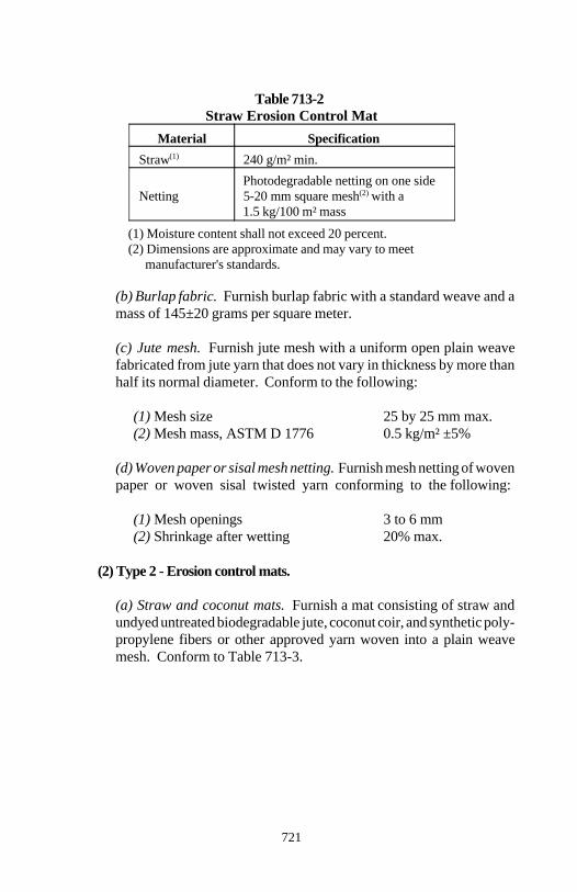
Section 713
721
Table 713-2Straw Erosion Control Mat
Material Specification
Straw 240 g/m² min.(1)
Netting 5-20 mm square mesh with aPhotodegradable netting on one side
(2)
1.5 kg/100 m² mass
(1) Moisture content shall not exceed 20 percent.(2) Dimensions are approximate and may vary to meet manufacturer's standards.
(b) Burlap fabric. Furnish burlap fabric with a standard weave and amass of 145±20 grams per square meter.
(c) Jute mesh. Furnish jute mesh with a uniform open plain weavefabricated from jute yarn that does not vary in thickness by more thanhalf its normal diameter. Conform to the following:
(1) Mesh size 25 by 25 mm max.(2) Mesh mass, ASTM D 1776 0.5 kg/m² ±5%
(d) Woven paper or sisal mesh netting. Furnish mesh netting of wovenpaper or woven sisal twisted yarn conforming to the following:
(1) Mesh openings 3 to 6 mm(2) Shrinkage after wetting 20% max.
(2) Type 2 - Erosion control mats.
(a) Straw and coconut mats. Furnish a mat consisting of straw andundyed untreated biodegradable jute, coconut coir, and synthetic poly-propylene fibers or other approved yarn woven into a plain weavemesh. Conform to Table 713-3.
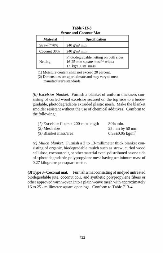
Section 713
722
Table 713-3Straw and Coconut Mat
Material Specification
Straw 70% 240 g/m² min.(1)
Coconut 30% 240 g/m² min.
Netting 16-25-mm square mesh with aPhotodegradable netting on both sides
(2)
1.5 kg/100 m² mass.
(1) Moisture content shall not exceed 20 percent.(2) Dimensions are approximate and may vary to meet
manufacturer's standards.
(b) Excelsior blanket. Furnish a blanket of uniform thickness con-sisting of curled wood excelsior secured on the top side to a biode-gradable, photodegradable extruded plastic mesh. Make the blanketsmolder resistant without the use of chemical additives. Conform tothe following:
(1) Excelsior fibers 200-mm length 80% min.(2) Mesh size 25 mm by 50 mm(3) Blanket mass/area 0.53±0.05 kg/m2
(c) Mulch blanket. Furnish a 3 to 13-millimeter thick blanket con-sisting of organic, biodegradable mulch such as straw, curled woodcellulose, coconut coir, or other material evenly distributed on one sideof a photodegradable, polypropylene mesh having a minimum mass of0.27 kilograms per square meter.
(3) Type 3 - Coconut mat. Furnish a mat consisting of undyed untreatedbiodegradable jute, coconut coir, and synthetic polypropylene fibers orother approved yarn woven into a plain weave mesh with approximately16 to 25 - millimeter square openings. Conform to Table 713-4.
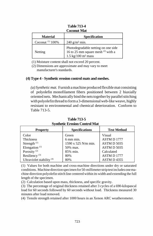
Section 713
723
Table 713-4Coconut Mat
Material Specification
Coconut 100% 240 g/m² min.(1)
Netting 16 to 25 mm square mesh with aPhotodegradable netting on one side
(2)
1.5 kg/100 m² mass
(1) Moisture content shall not exceed 20 percent.(2) Dimensions are approximate and may vary to meet
manufacturer's standards.
(4) Type 4 - Synthetic erosion control mats and meshes.
(a) Synthetic mat. Furnish a machine produced flexible mat consistingof polyolefin monofilament fibers positioned between 2 biaxiallyoriented nets. Mechanically bind the nets together by parallel stitchingwith polyolefin thread to form a 3-dimensional web-like weave, highlyresistant to environmental and chemical deterioration. Conform toTable 713-5.
Table 713-5Synthetic Erosion Control Mat
Property Specifications Test MethodColor Green VisualThickness 6 mm min. ASTM D 1777Strength 1590 x 525 N/m min. ASTM D 5035(1)
Elongation 50% max. ASTM D 5035(1)
Porosity 85% min. Calculated(2)
Resiliency 80% ASTM D 1777(3)
Ultraviolet stability 80% ASTM D 4355(4)
(1) Values for both machine and cross-machine directions under dry or saturatedconditions. Machine direction specimen for 50-millimeter strip test includes one ma-chine direction polyolefin stitch line centered within its width and extending the fulllength of the specimen.(2) Calculation based upon mass, thickness, and specific gravity. (3) The percentage of original thickness retained after 3 cycles of a 690-kilopascalload for 60 seconds followed by 60 seconds without load. Thickness measured 30minutes after load removed.(4) Tensile strength retained after 1000 hours in an Xenon ARC weatherometer.
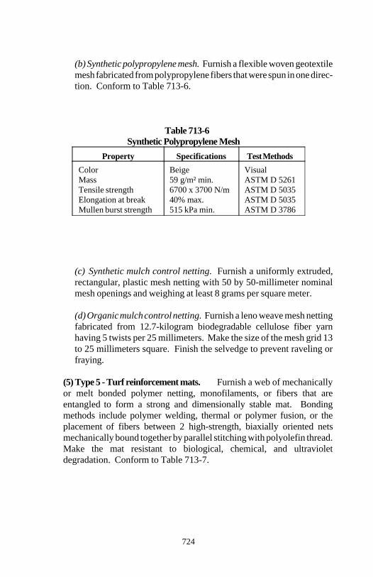
Section 713
724
(b) Synthetic polypropylene mesh. Furnish a flexible woven geotextilemesh fabricated from polypropylene fibers that were spun in one direc-tion. Conform to Table 713-6.
Table 713-6Synthetic Polypropylene Mesh
Property Specifications Test Methods
Color Beige VisualMass 59 g/m² min. ASTM D 5261Tensile strength 6700 x 3700 N/m ASTM D 5035Elongation at break 40% max. ASTM D 5035Mullen burst strength 515 kPa min. ASTM D 3786
(c) Synthetic mulch control netting. Furnish a uniformly extruded,rectangular, plastic mesh netting with 50 by 50-millimeter nominalmesh openings and weighing at least 8 grams per square meter.
(d) Organic mulch control netting. Furnish a leno weave mesh nettingfabricated from 12.7-kilogram biodegradable cellulose fiber yarnhaving 5 twists per 25 millimeters. Make the size of the mesh grid 13to 25 millimeters square. Finish the selvedge to prevent raveling orfraying.
(5) Type 5 - Turf reinforcement mats. Furnish a web of mechanicallyor melt bonded polymer netting, monofilaments, or fibers that areentangled to form a strong and dimensionally stable mat. Bondingmethods include polymer welding, thermal or polymer fusion, or theplacement of fibers between 2 high-strength, biaxially oriented netsmechanically bound together by parallel stitching with polyolefin thread.Make the mat resistant to biological, chemical, and ultravioletdegradation. Conform to Table 713-7.
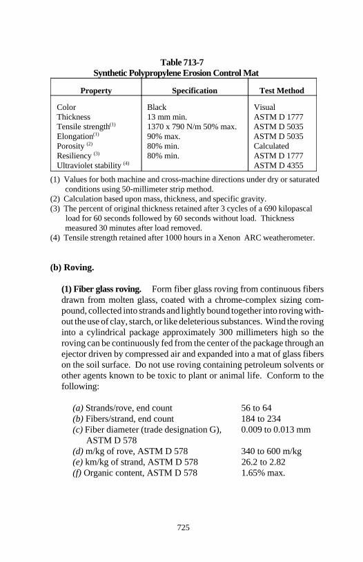
Section 713
725
Table 713-7Synthetic Polypropylene Erosion Control Mat
Property Specification Test Method
Color Black VisualThickness 13 mm min. ASTM D 1777Tensile strength 1370 x 790 N/m 50% max. ASTM D 5035(1)
Elongation 90% max. ASTM D 5035(1)
Porosity 80% min. Calculated(2)
Resiliency 80% min. ASTM D 1777(3)
Ultraviolet stability ASTM D 4355(4)
(1) Values for both machine and cross-machine directions under dry or saturated conditions using 50-millimeter strip method.
(2) Calculation based upon mass, thickness, and specific gravity.(3) The percent of original thickness retained after 3 cycles of a 690 kilopascal
load for 60 seconds followed by 60 seconds without load. Thickness measured 30 minutes after load removed.
(4) Tensile strength retained after 1000 hours in a Xenon ARC weatherometer.
(b) Roving.
(1) Fiber glass roving. Form fiber glass roving from continuous fibersdrawn from molten glass, coated with a chrome-complex sizing com-pound, collected into strands and lightly bound together into roving with-out the use of clay, starch, or like deleterious substances. Wind the rovinginto a cylindrical package approximately 300 millimeters high so theroving can be continuously fed from the center of the package through anejector driven by compressed air and expanded into a mat of glass fiberson the soil surface. Do not use roving containing petroleum solvents orother agents known to be toxic to plant or animal life. Conform to thefollowing:
(a) Strands/rove, end count 56 to 64(b) Fibers/strand, end count 184 to 234(c) Fiber diameter (trade designation G), 0.009 to 0.013 mm
ASTM D 578(d) m/kg of rove, ASTM D 578 340 to 600 m/kg(e) km/kg of strand, ASTM D 578 26.2 to 2.82(f) Organic content, ASTM D 578 1.65% max.
Section 713
726
(2) Polypropylene roving. Form polypropylene roving from continuousstrands of fibrillated polypropylene yarn. Wind the roving into a cylindri-cal package so the roving can be continuously fed from the outside of thepackage through an ejector driven by compressed air and expanded intoa mat of polypropylene strands. The material shall contain no agents thatare toxic to plant or animal life. Conform to the following:
(a) Tensile strength, ASTM D 2256 15.6 N(b) Elongation at break, ASTM D 2256 15.5%(c) Mass of strand, ASTM D 1907 360 denier(d) Strands per rove, measured 24(e) UV stability, ASTM D 4355 50% retained after 200
hours
(c) Geocell (cellular confinement system). Furnish a flexible honeycomb3-dimensional structure fabricated from polyethylene that has been properlystabilized with carbon black and/or hindered aminc light stabilizers.
713.08 Miscellaneous Planting Material.
(a) Stakes for bracing and anchoring. Conform to the American LumberStandards. Fabricate stakes for bracing and anchoring trees from roughcypress, cedar, locust, or other approved wood essentially free from knots,rot, crossgrain, or other defects that would impair the strength of the stake.Furnish stakes with a minimum 50 by 50-millimeter square cross-section andadequate length.
Furnish anchor stakes of the same size and quality as bracing stakes. Thediameter and length of the deadman is specified in the contract.
(b) Hose. Furnish 25-millimeter diameter garden or steam hose (rubber andfabric) to be used with wire for bracing and anchoring trees.
(c) Wire. Furnish 3.8-millimeter diameter soft annealed galvanized steelwire for bracing and anchoring trees.
(d) Wrapping material. Furnish 100-millimeter wide rolls of waterproofpaper (triple lamination 30-30-30) or 150-millimeter wide rolls of burlap forwrapping trees.
Section 713
727
(e) Twine. Furnish 2-ply twine for trees 75 millimeters and less in diameterand 3-ply twine for trees over 75 millimeters in diameter for tying wrappingmaterial to the trees.
(f) Antidesiccant. If approved, furnish a commercially available antidesicc-ant emulsion to provide a film over plant surfaces that is permeable enoughto permit transpiration.
(g) Tree wound dressing. Furnish a commercially available product withasphalt base and fungicide. Furnish material that is antiseptic, waterp-roof, adhesive, and elastic. Do not use material that is harmful to living treetissue such as kerosene, coal tar, or creosote.
713.09 Sprigs. Furnish healthy living stems (stolons or rhizomes) andattached roots of the perennial turf-forming grasses specified in the contract.Obtain sprigs from approved heavy and thickly matted sources in the localityof the work. Remove all johnson grass or other objectionable grasses, weeds,or other detrimental material.
713.10 Sod. Furnish living vigorous sod of the type of grass and thicknessspecified in the contract. Furnish sod with a dense root system that isreasonably free from noxious weeds and grasses. Before taking up the sod, cutthe top growth to less than 75-millimeter height.
713.11 Pegs for Sod. Furnish square or round pegs of sound wood and con-form to the following:
(a) Length 200 mm min.(b) Approximate cross-sectional area 600 mm2
713.12 Stabilizing Emulsion Tackifiers. Furnish a commercially availableproduct containing no solvents or other diluting agents toxic to plant life.Conform to one of the following:
(a) Emulsified asphalt grades SS-1, SS-1h, CSS-1, or CSS-1h.(b) Nonasphalt emulsions having a water soluble natural vegetable gum,blended with gelling and hardening agents or a water soluble blend ofhydrophilic polymers, viscosifiers, sticking agents, and gums.(c) Polyvinyl acetate using emulsion resins and containing 60±1 percent totalsolids by mass.
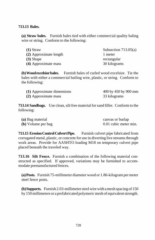
Section 713
728
713.13 Bales.
(a) Straw bales. Furnish bales tied with either commercial quality balingwire or string. Conform to the following:
(1) Straw Subsection 713.05(a)(2) Approximate length 1 meter(3) Shape rectangular(4) Approximate mass 30 kilograms
(b) Wood excelsior bales. Furnish bales of curled wood excelsior. Tie thebales with either a commercial bailing wire, plastic, or string. Conform tothe following:
(1) Approximate dimensions 400 by 450 by 900 mm(2) Approximate mass 33 kilograms
713.14 Sandbags. Use clean, silt free material for sand filler. Conform to thefollowing:
(a) Bag material canvas or burlap(b) Volume per bag 0.01 cubic meter min.
713.15 Erosion Control Culvert Pipe. Furnish culvert pipe fabricated fromcorrugated metal, plastic, or concrete for use in diverting live streams throughwork areas. Provide for AASHTO loading M18 on temporary culvert pipeplaced beneath the traveled way.
713.16 Silt Fence. Furnish a combination of the following material con-structed as specified. If approved, variations may be furnished to accom-modate premanufactured fences.
(a) Posts. Furnish 75-millimeter diameter wood or 1.86-kilogram per metersteel fence posts.
(b) Supports. Furnish 2.03-millimeter steel wire with a mesh spacing of 150by 150 millimeters or a prefabricated polymeric mesh of equivalent strength.
Section 713
729
(c) Geotextile. Conform to Subsection 714.01 and Table 714-5 asapplicable.
(d) Height. Minimum height above the ground is 760 millimeters. Mini-mum embedment depth is 150 millimeters.
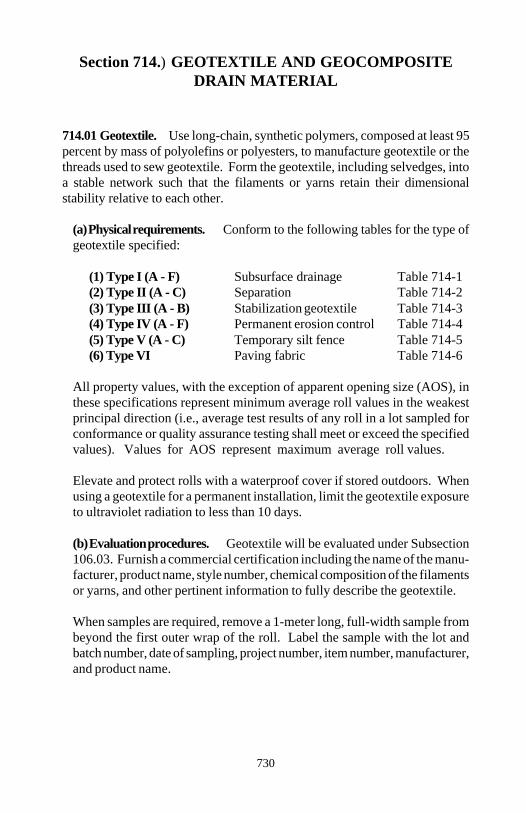
730
Section 714.) GEOTEXTILE AND GEOCOMPOSITEDRAIN MATERIAL
714.01 Geotextile. Use long-chain, synthetic polymers, composed at least 95percent by mass of polyolefins or polyesters, to manufacture geotextile or thethreads used to sew geotextile. Form the geotextile, including selvedges, intoa stable network such that the filaments or yarns retain their dimensionalstability relative to each other.
(a) Physical requirements. Conform to the following tables for the type ofgeotextile specified:
(1) Type I (A - F) Subsurface drainage Table 714-1(2) Type II (A - C) Separation Table 714-2(3) Type III (A - B) Stabilization geotextile Table 714-3(4) Type IV (A - F) Permanent erosion control Table 714-4(5) Type V (A - C) Temporary silt fence Table 714-5(6) Type VI Paving fabric Table 714-6
All property values, with the exception of apparent opening size (AOS), inthese specifications represent minimum average roll values in the weakestprincipal direction (i.e., average test results of any roll in a lot sampled forconformance or quality assurance testing shall meet or exceed the specifiedvalues). Values for AOS represent maximum average roll values.
Elevate and protect rolls with a waterproof cover if stored outdoors. Whenusing a geotextile for a permanent installation, limit the geotextile exposureto ultraviolet radiation to less than 10 days.
(b) Evaluation procedures. Geotextile will be evaluated under Subsection106.03. Furnish a commercial certification including the name of the manu-facturer, product name, style number, chemical composition of the filamentsor yarns, and other pertinent information to fully describe the geotextile.
When samples are required, remove a 1-meter long, full-width sample frombeyond the first outer wrap of the roll. Label the sample with the lot andbatch number, date of sampling, project number, item number, manufacturer,and product name.

Section 714
731
In addition, when geotextile joints are sewn, submit the seam assemblydescription and a sample of the sewn material. This description shall includethe seam type, seam allowance, stitch type, sewing thread tex ticketnumber(s) and type(s), stitch density, and stitch gauge. If the productionseams are sewn in both the machine and cross-machine directions, providesample sewn seams that are oriented in both the machine and cross-ma-chine directions. Furnish a sewn sample that has at least 2 meters of sewnseam and is at least 1.5 meters wide. Sew the sample seams with the sameequipment and procedures that are used to sew the production seams. Forseams sewn on-site, conform to the manufacturer's recommendations.Obtain approval of the seam before installation.
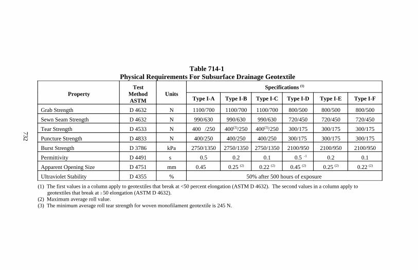
Section 714
732
Table 714-1Physical Requirements For Subsurface Drainage Geotextile
PropertyTest
MethodASTM
UnitsSpecifications (1)
Type I-A Type I-B Type I-C Type I-D Type I-E Type I-F
Grab Strength D 4632 N 1100/700 1100/700 1100/700 800/500 800/500 800/500
Sewn Seam Strength D 4632 N 990/630 990/630 990/630 720/450 720/450 720/450
Tear Strength D 4533 N 400 /250 (3)400 /250(3) 400 /250(3) 300/175 300/175 300/175
Puncture Strength D 4833 N 400/250 400/250 400/250 300/175 300/175 300/175
Burst Strength D 3786 kPa 2750/1350 2750/1350 2750/1350 2100/950 2100/950 2100/950
Permittivity D 4491 s -10.5 0.2 0.1 0.5 0.2 0.1
Apparent Opening Size D 4751 mm 0.45 0.25 (2) 0.22 (2) 0.45 (2) 0.25 (2) 0.22 (2)
Ultraviolet Stability D 4355 % 50% after 500 hours of exposure
(1) The first values in a column apply to geotextiles that break at <50 percent elongation (ASTM D 4632). The second values in a column apply to geotextiles that break at 50 elongation (ASTM D 4632).
(2) Maximum average roll value.(3) The minimum average roll tear strength for woven monofilament geotextile is 245 N.
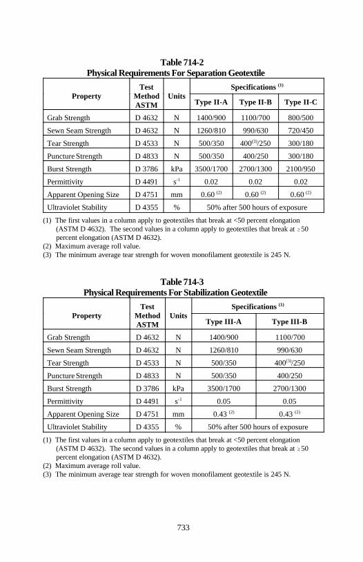
Section 714
733
Table 714-2Physical Requirements For Separation Geotextile
Property Method UnitsTest Specifications
ASTM
(1)
Type II-A Type II-B Type II-C
Grab Strength D 4632 N 1400/900 1100/700 800/500
Sewn Seam Strength D 4632 N 1260/810 990/630 720/450
Tear Strength D 4533 N 500/350 400 /250 300/180(3)
Puncture Strength D 4833 N 500/350 400/250 300/180
Burst Strength D 3786 kPa 3500/1700 2700/1300 2100/950
Permittivity D 4491 s 0.02 0.02 0.02-1
Apparent Opening Size D 4751 mm 0.60 0.60 0.60 (2) (2) (2)
Ultraviolet Stability D 4355 % 50% after 500 hours of exposure
(1) The first values in a column apply to geotextiles that break at <50 percent elongation (ASTM D 4632). The second values in a column apply to geotextiles that break at 50 percent elongation (ASTM D 4632).
(2) Maximum average roll value.(3) The minimum average tear strength for woven monofilament geotextile is 245 N.
Table 714-3Physical Requirements For Stabilization Geotextile
Property Method UnitsTest Specifications
ASTM
(1)
Type III-A Type III-B
Grab Strength D 4632 N 1400/900 1100/700
Sewn Seam Strength D 4632 N 1260/810 990/630
Tear Strength D 4533 N 500/350 400 /250(3)
Puncture Strength D 4833 N 500/350 400/250
Burst Strength D 3786 kPa 3500/1700 2700/1300
Permittivity D 4491 s 0.05 0.05-1
Apparent Opening Size D 4751 mm 0.43 0.43 (2) (2)
Ultraviolet Stability D 4355 % 50% after 500 hours of exposure
(1) The first values in a column apply to geotextiles that break at <50 percent elongation (ASTM D 4632). The second values in a column apply to geotextiles that break at 50 percent elongation (ASTM D 4632).
(2) Maximum average roll value.(3) The minimum average tear strength for woven monofilament geotextile is 245 N.
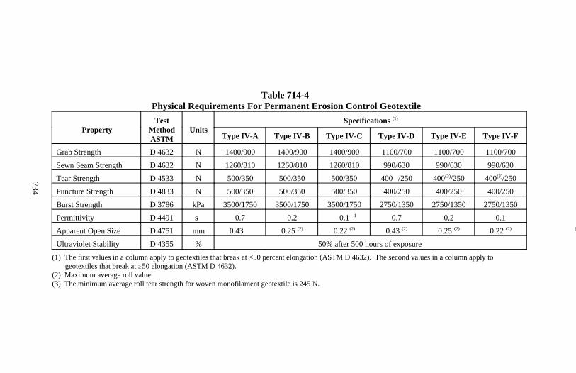
Section 714
734
Table 714-4Physical Requirements For Permanent Erosion Control Geotextile
PropertyTest
MethodASTM
UnitsSpecifications (1)
Type IV-A Type IV-B Type IV-C Type IV-D Type IV-E Type IV-F
Grab Strength D 4632 N 1400/900 1400/900 1400/900 1100/700 1100/700 1100/700
Sewn Seam Strength D 4632 N 1260/810 1260/810 1260/810 990/630 990/630 990/630
Tear Strength D 4533 N 500/350 500/350 500/350 400 /250 400 /250(3) 400 /250(3)
Puncture Strength D 4833 N 500/350 500/350 500/350 400/250 400/250 400/250
Burst Strength D 3786 kPa 3500/1750 3500/1750 3500/1750 2750/1350 2750/1350 2750/1350
Permittivity D 4491 s -10.7 0.2 0.1 0.7 0.2 0.1
Apparent Open Size D 4751 mm 0.43 (2)0.25 (2) 0.22 (2) 0.43 (2) 0.25 (2) 0.22 (2)
Ultraviolet Stability D 4355 % 50% after 500 hours of exposure
(1) The first values in a column apply to geotextiles that break at <50 percent elongation (ASTM D 4632). The second values in a column apply to geotextiles that break at 50 elongation (ASTM D 4632).
(2) Maximum average roll value.(3) The minimum average roll tear strength for woven monofilament geotextile is 245 N.
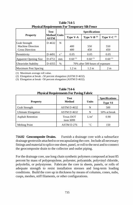
Section 714
735
Table 714-5Physical Requirements For Temporary Silt Fence
Property Method UnitsTest Specifications
ASTM Type V-A Type V-B Type V-C (2) (3)
Grab Strength D 4632 N Machine Direction 400 550 550 Cross Direction 400 450 450
Permittivity D 4491 s 0.05 0.05 0.05 -1
Apparent Opening Size D 4751 mm 0.60 0.60 0.60 (1) (1) (1)
Ultraviolet Stability D 4355 % 70% after 500 hours of exposure
Maximum Post Spacing 1.2 m 1.2 m 2 m
(1) Maximum average roll value.(2) Elongation at break 50 percent elongation (ASTM D 4632).(3) Elongation at break <50 percent elongation (ASTM D 4632).
Table 714-6Physical Requirements For Paving Fabric
Property Method UnitsTest Specifications
Type VI
Grab Strength ASTM D 4632 N 500
Ultimate Elongation ASTM D 4632 N 50% at break
Asphalt Retention Texas DOT L/m 0.90item 3099
2
Melting Point ASTM D 276 C 150
714.02 Geocomposite Drains. Furnish a drainage core with a subsurfacedrainage geotextile attached to or encapsulating the core. Include all necessaryfittings and material to splice one sheet, panel, or roll to the next and to connectthe geocomposite drain to the collector and outlet piping.
For the drainage core, use long chain synthetic polymers composed at least 85percent by mass of polypropylene, polyester, polyamide, polyvinyl chloride,polyolefin, or polystyrene. Fabricate the core in sheets, panels, or rolls ofadequate strength to resist installation stresses and long-term loadingconditions. Build the core up in thickness by means of columns, cones, nubs,cusps, meshes, stiff filaments, or other configurations.
Section 714
736
Furnish geocomposite drains with a minimum compressive strength of 275kilopascals when tested according to ASTM D 1621 procedure A. Furnishsplices, fittings, and connections with sufficient strength to maintain theintegrity of the system during construction handling and permanent loadingwithout impeding flow or damaging the core.
Elevate and protect sheets, panels, or rolls with a waterproof and ultravioletresistant cover if stored outdoors.
When using a geocomposite drain for a permanent installation, limit thegeocomposite exposure to ultraviolet radiation to less than 10 days.
Geocomposites will be evaluated under Subsection 106.03. When samples arerequired, provide a 1-meter square sample from products supplied as sheets orpanels or a 1-meter length full-roll width sample from products supplied inrolls. Label the sample with the lot and batch number, date of sampling,project number, item number, manufacturer, and product name.
(a) Geocomposite underdrains. The horizontal and vertical flow of waterwithin the core shall interconnect at all times for the full height of the core.The drainage core with the geotextile fully encapsulating the core shall pro-vide a minimum flow rate of 1 liter per second per meter of width whentested according to ASTM D 4716 under the following test conditions:
(1) 300-millimeter long specimen(2) Applied load of 69 kilopascals(3) Gradient of 0.1(4) 100-hour seating period(5) Closed-cell foam rubber between platens and geocomposite
Firmly attach the geotextile to the core so folding, wrinkling, or other move-ment cannot occur either during handling or after placement. Achievebonding using nonwater-soluble adhesive, heat sealing, or other methodsrecommended by the manufacturer. Do not use adhesive on areas of thegeotextile fabric where flow is intended to occur.
If heat sealing is used, do not weaken the geotextile below the requiredstrength values. Extend the geotextile below the bottom of the core a lengthsufficient to completely encapsulate the collector pipe.
Section 714
737
(b) Geocomposite sheet drains. The horizontal and vertical flow of waterwithin the sheet drain shall interconnect at all times for the full height of thecore. The drainage core with the geotextile laminated to one side of the coreshall provide a minimum flow rate of 1 liter per second per meter of widthwhen tested according to ASTM D 4716 under test conditions (1) through (5)in (a) above, except the gradient shall be 1.0.
If core construction separates the flow channel into two or more sections,only the flow rate on the in-flow face is considered in determining the core'sacceptability.
Firmly attach the geotextile to the core so folding, wrinkling, or other move-ment cannot occur either during handling or after placement. Achievebonding using nonwater-soluble adhesive, heat sealing, or other methodrecommended by the manufacturer. Do not use adhesive on areas of thegeotextile fabric where flow is intended to occur.
If heat sealing is used, do not weaken the geotextile below the requiredstrength values. Extend the geotextile below the bottom of the core lengthsufficient to completely encapsulate the collector pipe.
(c) Geocomposite pavement edge drains. The geotextile shall tightlyencapsulate the geocomposite edge drain. The edge drains shall permit in-flow from both sides. The drain core with the geotextile in place shallprovide a minimum flow rate of 3 liters per second per meter of width whentested according to ASTM D 4716 under test conditions (1) through (5) in(a) above.
If the geocomposite polymer core separates the flow channel into two ormore parts, consider only the tested flow rate of the channel facing thepavement.
All pipe and pipe fittings used for an outlet to the edge drain shall be non-perforated plastic pipe conforming to Subsection 706.08.
The solvent cement for the outlet pipe and fittings shall be according toASTM D 2564. The material composition of the outlet fittings shall becompatible for direct solvent welding to PVC.
738
Section 715.) PILING
715.01 Untreated Timber Piles. Conform to ASTM D 25. Fabricate thepiles from the following species for the sizes and dimensions specified in thecontract:
(a) Douglas fir(b) Larch(c) Norway pine(d) Red oak(e) Southern yellow pine
Install steel straps along the length of the pile at not more than 3-meter centers.In addition, place a strap at 75, 150, and 300 millimeters from the tip and 2additional straps within 600 millimeters of the butt. Use 32-millimeter wideby 0.8-millimeter thick steel strapping material fabricated from cold-rolled,heat-treated, high-tensile steel having a minimum tensile strength of 22kilonewtons.
Hold straps in place with clips that are secured by crimping twice in the cliplength with a notch type sealer. Fabricate the clips from 57-millimeter by 0.9-millimeter thick steel. The clip joint shall develop at least 75 percent of thestrap tensile strength. Straps shall encircle the pile once and be tightened byhand operated or power assisted tensioning tools.
715.02 Treated Timber Piles. Conform to Subsection 715.01, except furnishonly Douglas fir or southern yellow pine piles for use in saltwater. Treat thepiles with preservative according to AASHTO M 133 for the types andquantities of preservatives specified in the contract.
Use the pressure method procedure prescribed in AWPA Standard C1. Applythe treatment to the piles after all millwork is completed.
Imprint legible symbols or legend on the end of all piles identifying the nameof the treating company and type and year of treatment according to AWPAStandards M1 and M6.
715.03 Concrete Piles. Fabricate piles from class A (AE) concrete con-forming to Section 552. For billet steel and rail steel reinforcement bars,conform to Subsection 709.01. For prestressing reinforcement steel, conformto Subsection 709.03.
Section 715
739
Construct precast concrete piles according to Section 552. Construct pre-stressed concrete piles according to Section 553. When lifting anchors areused, maintain at least a 25-millimeter clearance from the pile reinforcing steelor prestressing steel.
Use metal, plywood, or dressed lumber forms that are watertight, rigid, and trueto line. Use a 25-millimeter chamfer strip in all corners of the forms.
Cast piles separately or, if alternate piles are cast in a tier, cast the intermediatepiles at least 4 days after the adjacent piles are poured. Separate piles cast intiers with tar paper or other suitable separating material. Place concrete in eachtier in a continuous operation that prevents the formation of stone pockets,honeycombs, or other defects. Leave forms in place for at least 24 hours.
Make piles straight so when a line is stretched from butt to tip on any face, theline is no more than 25 millimeters from the face of the pile at any point. Makethe pile surface true, smooth, even, and free from honeycombs and voids.
Remove lifting anchors to a depth of at least 25 millimeters below the concretesurface and fill the resulting hole with concrete. Finish the surface of each pilewith a class 1 ordinary surface finish according to Subsection 552.16. Cure thepiles according to Sections 552 and 553 as applicable.
If concrete test cylinders are made and tested according to Section 552, do notmove piles until the tests indicate a compressive strength of at least 80 percentof the design 28-day compressive strength. Do not transport or drive piles untiltests indicate the minimum design 28-day compressive strength is attained.
If concrete test cylinders are not made, do not move piles until they have curedfor at least 14 days at a minimum temperature of 15 C or 21 days at aminimum temperature of 4 C. Do not transport or drive piles until cured forat least 21 days at a minimum of 15 C or 28 days at a minimum of 4 C.When high-early-strength cement is used, do not move, transport, or drive pilesuntil cured for at least 7 days.
Section 715
740
715.04 Steel Shells. Furnish either cylindrical or tapered pile shells of spiralwelded, straight-seam welded, or seamless tube steel material. Use only onetype of pile shell throughout a structure. Conform to the following minimumshell wall thicknesses:
• Outside cylinder diameter < 350 mm 6 mm• Outside cylinder diameter 350 mm 10 mm• Tapered or fluted 4.5 mm
(a) Shells driven without a mandrel. For tapered or step tapered cast-in-place concrete piles, furnish shells having a minimum 300-millimeterdiameter at cutoff and a minimum 200-millimeter diameter tip. For constantdiameter cast-in-place concrete piles, furnish shells having a minimum nomi-nal diameter of 270 millimeters.
Fabricate shells from not less than 4.5-millimeter plate stock conforming toAASHTO M 183M. Shells may be either spirally welded or longitudinallywelded and may be either tapered or constant in section. Seal the tips asnoted on the drawings.
(b) Shells driven with a mandrel. Furnish shells of sufficient strength andthickness to withstand driving without injury and to resist harmful distortionand/or buckling due to soil pressure after being driven and the mandrelremoved. Butt and tip dimensions are specified in the contract.
715.05 Steel Pipes. Conform to the following:
(a) Steel pipe to be filled with concrete ASTM A 252 grade 2(b) Closure plates for closed end piles AASHTO M 183M(c) Reinforced conical points AASHTO M 103Mfor pipe closure at the tip(d) Unfilled tubular steel piles for welded and ASTM A 252 grade 2seamless steel pipe piles with chemical properties conforming to ASTM A 53 grade B
715.06 Steel H-Piles. Furnish steel H-piles from rolled steel sections of themass and shape specified in the contract. Fabricate the H-piles from structuralsteel conforming to AASHTO M 183M, except do not use steel manufacturedby the acid-bessemer process.

Section 715
741
For copper-bearing structural steel, furnish steel with 0.20 to 0.35 percentcopper.
715.07 Sheet Piles. For steel sheet piles, conform to AASHTO M 202M orM 223M. For all other sheet piles, conform to the requirements prescribedabove for the particular material specified. Make the joints practically water-tight when the piles are in place.
715.08 Pile Shoes. For timber piles, prefabricate shoes from cast steel con-forming to ASTM A 27M.
715.09 Splices. For H or pipe piles, manufacture splices from structural steelconforming to AASHTO M 183M.
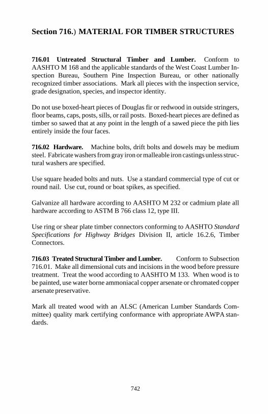
742
Section 716.) MATERIAL FOR TIMBER STRUCTURES
716.01 Untreated Structural Timber and Lumber. Conform toAASHTO M 168 and the applicable standards of the West Coast Lumber In-spection Bureau, Southern Pine Inspection Bureau, or other nationallyrecognized timber associations. Mark all pieces with the inspection service,grade designation, species, and inspector identity.
Do not use boxed-heart pieces of Douglas fir or redwood in outside stringers,floor beams, caps, posts, sills, or rail posts. Boxed-heart pieces are defined astimber so sawed that at any point in the length of a sawed piece the pith liesentirely inside the four faces. 716.02 Hardware. Machine bolts, drift bolts and dowels may be mediumsteel. Fabricate washers from gray iron or malleable iron castings unless struc-tural washers are specified.
Use square headed bolts and nuts. Use a standard commercial type of cut orround nail. Use cut, round or boat spikes, as specified.
Galvanize all hardware according to AASHTO M 232 or cadmium plate allhardware according to ASTM B 766 class 12, type III.
Use ring or shear plate timber connectors conforming to AASHTO StandardSpecifications for Highway Bridges Division II, article 16.2.6, TimberConnectors.
716.03 Treated Structural Timber and Lumber. Conform to Subsection716.01. Make all dimensional cuts and incisions in the wood before pressuretreatment. Treat the wood according to AASHTO M 133. When wood is tobe painted, use water borne ammoniacal copper arsenate or chromated copperarsenate preservative.
Mark all treated wood with an ALSC (American Lumber Standards Com-mittee) quality mark certifying conformance with appropriate AWPA stan-dards.
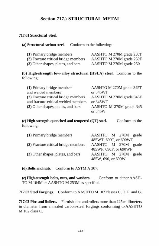
743
Section 717.) STRUCTURAL METAL
717.01 Structural Steel.
(a) Structural carbon steel. Conform to the following:
(1) Primary bridge members AASHTO M 270M grade 250T(2) Fracture critical bridge members AASHTO M 270M grade 250F(3) Other shapes, plates, and bars AASHTO M 270M grade 250
(b) High-strength low-alloy structural (HSLA) steel. Conform to thefollowing:
(1) Primary bridge members AASHTO M 270M grade 345Tand welded members or 345WT(2) Fracture critical bridge members AASHTO M 270M grade 345Fand fracture critical welded members or 345WF(3) Other shapes, plates, and bars AASHTO M 270M grade 345
or 345W
(c) High-strength quenched and tempered (QT) steel. Conform to thefollowing:
(1) Primary bridge members AASHTO M 270M grade485WT, 690T, or 690WT
(2) Fracture critical bridge members AASHTO M 270M grade485WF, 690F, or 690WF
(3) Other shapes, plates, and bars AASHTO M 270M grade485W, 690, or 690W
(d) Bolts and nuts. Conform to ASTM A 307.
(e) High-strength bolts, nuts, and washers. Conform to either AASH-TO M 164M or AASHTO M 253M as specified.
717.02 Steel Forgings. Conform to AASHTO M 102 classes C, D, F, and G.
717.03 Pins and Rollers. Furnish pins and rollers more than 225 millimetersin diameter from annealed carbon-steel forgings conforming to AASHTOM 102 class C.
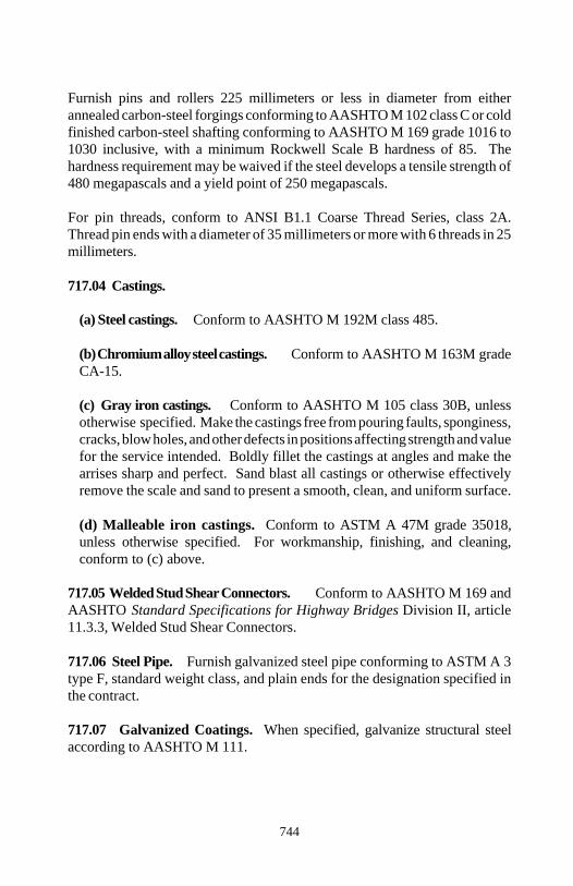
Section 717
744
Furnish pins and rollers 225 millimeters or less in diameter from eitherannealed carbon-steel forgings conforming to AASHTO M 102 class C or coldfinished carbon-steel shafting conforming to AASHTO M 169 grade 1016 to1030 inclusive, with a minimum Rockwell Scale B hardness of 85. Thehardness requirement may be waived if the steel develops a tensile strength of480 megapascals and a yield point of 250 megapascals.
For pin threads, conform to ANSI B1.1 Coarse Thread Series, class 2A.Thread pin ends with a diameter of 35 millimeters or more with 6 threads in 25millimeters.
717.04 Castings.
(a) Steel castings. Conform to AASHTO M 192M class 485.
(b) Chromium alloy steel castings. Conform to AASHTO M 163M gradeCA-15.
(c) Gray iron castings. Conform to AASHTO M 105 class 30B, unlessotherwise specified. Make the castings free from pouring faults, sponginess,cracks, blow holes, and other defects in positions affecting strength and valuefor the service intended. Boldly fillet the castings at angles and make thearrises sharp and perfect. Sand blast all castings or otherwise effectivelyremove the scale and sand to present a smooth, clean, and uniform surface.
(d) Malleable iron castings. Conform to ASTM A 47M grade 35018,unless otherwise specified. For workmanship, finishing, and cleaning,conform to (c) above.
717.05 Welded Stud Shear Connectors. Conform to AASHTO M 169 andAASHTO Standard Specifications for Highway Bridges Division II, article11.3.3, Welded Stud Shear Connectors.
717.06 Steel Pipe. Furnish galvanized steel pipe conforming to ASTM A 3type F, standard weight class, and plain ends for the designation specified inthe contract.
717.07 Galvanized Coatings. When specified, galvanize structural steelaccording to AASHTO M 111.
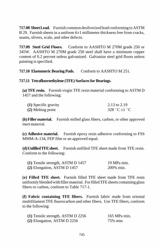
Section 717
745
717.08 Sheet Lead. Furnish common desilverized lead conforming to ASTMB 29. Furnish sheets in a uniform 6±1 millimeter thickness free from cracks,seams, slivers, scale, and other defects.
717.09 Steel Grid Floors. Conform to AASHTO M 270M grade 250 or345W. AASHTO M 270M grade 250 steel shall have a minimum coppercontent of 0.2 percent unless galvanized. Galvanize steel grid floors unlesspainting is specified.
717.10 Elastomeric Bearing Pads. Conform to AASHTO M 251.
717.11 Tetrafluoroethylene (TFE) Surfaces for Bearings.
(a) TFE resin. Furnish virgin TFE resin material conforming to ASTM D1457 and the following:
(1) Specific gravity 2.13 to 2.19(2) Melting point 328 C ±1 C
(b) Filler material. Furnish milled glass fibers, carbon, or other approvedinert material.
(c) Adhesive material. Furnish epoxy resin adhesive conforming to FSSMMM-A-134, FEP film or an approved equal.
(d) Unfilled TFE sheet. Furnish unfilled TFE sheet made from TFE resin.Conform to the following:
(1) Tensile strength, ASTM D 1457 19 MPa min.(2) Elongation, ASTM D 1457 200% min.
(e) Filled TFE sheet. Furnish filled TFE sheet made from TFE resinuniformly blended with filler material. For filled TFE sheets containing glassfibers or carbon, conform to Table 717-1.
(f) Fabric containing TFE fibers. Furnish fabric made from orientalmultifilament TFE fluorocarbon and other fibers. Use TFE fibers, conformto the following:
(1) Tensile strength, ASTM D 2256 165 MPa min.(2) Elongation, ASTM D 2256 75% min.

Section 717
746
Table 717-1Filled Tetrafluoroethylene Sheeting
Property 15% Glass Fibers 25% CarbonASTMMethod
Mechanical: Min. tensile strength D 1457 14 MPa 9 MPa
Min. elongation D 1457 150% 75%
Physical: Min. specific gravity D 792 2.20 2.10
Melting point D 1457 327±10 C 327±10 C
(g) Interlocked bronze and filled TFE components. Furnish a phosphorbronze plate conforming to ASTM B 100 with an 0.25 millimeter thickporous bronze surface layer conforming to ASTM B 103M into which isimpregnated a TFE compound. Overlay the surface with compounded TFEnot less than 25 micrometers thick.
(h) TFE metal composite. Furnish virgin TFE molded on each side andcompletely through a 33-millimeter perforated stainless steel sheet con-forming to ASTM A 240 type 304.
(i) Surface treatment. For epoxy bonding, factory treat one side of the TFEsheet with a sodium napthalene or sodium ammonia process.
(j) Stainless steel mating surface. Conform to ASTM A 240 type 304 andthe following:
(1) Thickness 0.91 mm min.(2) Surface finish 0.5 µm root mean square max.
Polish or roll stainless steel mating surfaces as necessary to meet the speci-fied friction properties.
717.12 Structural Aluminum Alloy. Conform to the Specifications for Alu-minum Structures published by the Aluminum Association, Inc. For aluminumexpansion joint material, furnish aluminum extrusion alloy 6061-T6.
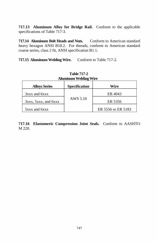
Section 717
747
717.13 Aluminum Alloy for Bridge Rail. Conform to the applicablespecifications of Table 717-3.
717.14 Aluminum Bolt Heads and Nuts. Conform to American standardheavy hexagon ANSI B18.2. For threads, conform to American standardcoarse series, class 2 fit, ANSI specification B1.1.
717.15 Aluminum Welding Wire. Conform to Table 717-2.
Table 717-2Aluminum Welding Wire
Alloys Series Specification Wire
3xxx and 6xxx ER 4043AWS 5.10
3xxx, 5xxx, and 6xxx ER 5356
5xxx and 6xxx ER 5556 or ER 5183
717.16 Elastomeric Compression Joint Seals. Conform to AASHTOM 220.
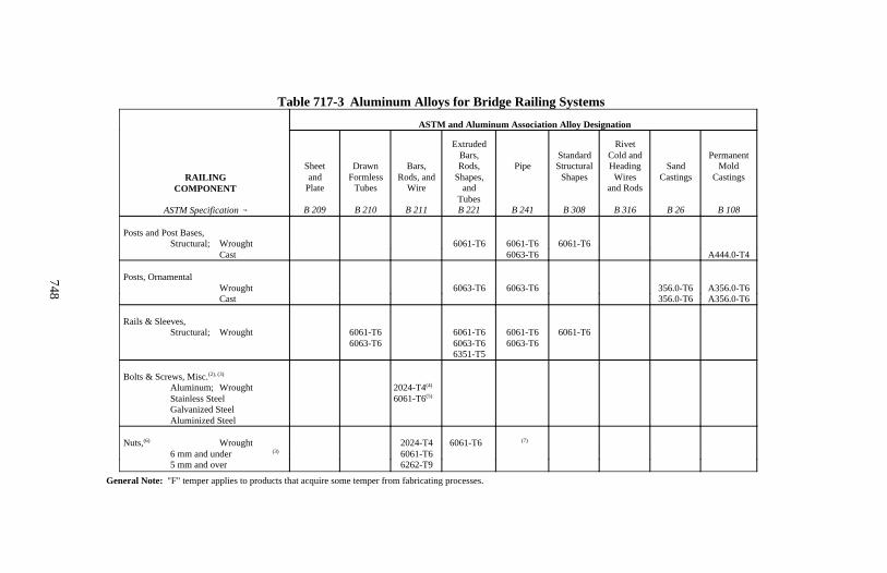
Section 717
748
Table 717-3 Aluminum Alloys for Bridge Railing Systems
ASTM and Aluminum Association Alloy Designation
RAILINGCOMPONENT
ASTM Specification
Sheetand
Plate
B 209
DrawnFormless
Tubes
B 210
Bars,Rods, and
Wire
B 211
ExtrudedBars,Rods,
Shapes,and
TubesB 221
Pipe
B 241
StandardStructural
Shapes
B 308
RivetCold andHeading
Wiresand Rods
B 316
SandCastings
B 26
PermanentMold
Castings
B 108
Posts and Post Bases,Structural; Wrought 6061-T6 6061-T6 6061-T6
Cast 6063-T6 A444.0-T4
Posts, OrnamentalWrought 6063-T6 6063-T6 356.0-T6 A356.0-T6Cast 356.0-T6 A356.0-T6
Rails & Sleeves,Structural; Wrought 6061-T6
6063-T66061-T66063-T66351-T5
6061-T66063-T6
6061-T6
Bolts & Screws, Misc.(2), (3)
Aluminum; WroughtStainless SteelGalvanized SteelAluminized Steel
2024-T4(4)
6061-T6(5)
Nuts, Wrought(6) 2024-T4 6061-T6 (7)
6 mm and under (3) 6061-T65 mm and over 6262-T9
General Note: "F" temper applies to products that acquire some temper from fabricating processes.
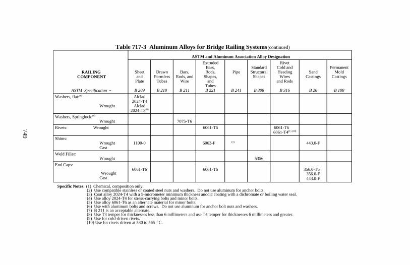
Section 717
749
Table 717-3 Aluminum Alloys for Bridge Railing Systems (continued)
ASTM and Aluminum Association Alloy Designation
RAILING COMPONENT
ASTM Specification
Sheetand
Plate
B 209
DrawnFormless
Tubes
B 210
Bars,Rods, and
Wire
B 211
ExtrudedBars,Rods,
Shapes,and
TubesB 221
Pipe
B 241
StandardStructural
Shapes
B 308
RivetCold andHeadingWires
and Rods
B 316
SandCastings
B 26
PermanentMold
Castings
B 108Washers, flat:(6)
Wrought
Alclad2024-T4Alclad
2024-T3(8)
Washers, Springlock:(6)
Wrought 7075-T6Rivets: Wrought 6061-T6 6061-T6
6061-T4(1) (10)
Shims:Wrought
Cast1100-0 6063-F (1) 443.0-F
Weld Filler:Wrought 5356
End Caps:
Wrought Cast
6061-T6 6061-T6 356.0-T6 (1)
356.0-F443.0-F
Specific Notes: (1) Chemical, composition only. (2) Use compatible stainless or coated steel nuts and washers. Do not use aluminum for anchor bolts. (3) Coat alloy 2024-T4 with a 5-micrometer minimum thickness anodic coating with a dichromate or boiling water seal. (4) Use alloy 2024-T4 for stress-carrying bolts and minor bolts. (5) Use alloy 6061-T6 as an alternate material for minor bolts. (6) Use with aluminum bolts and screws. Do not use aluminum for anchor bolt nuts and washers. (7) B 211 is an acceptable alternate. (8) Use T3 temper for thicknesses less than 6 millimeters and use T4 temper for thicknesses 6 millimeters and greater. (9) Use for cold-driven rivets. (10) Use for rivets driven at 530 to 565 C.
750
Section 718.) TRAFFIC SIGNING ANDMARKING MATERIAL
718.01 Retroreflective Sheeting. Conform to ASTM D 4956, except theminimum coefficients of retroreflection for brown type I sheeting shown inASTM D 4956 Table 1, Type I Sheeting, are amended as follows: 2.0 candelaper lux per square meter at 0.2 degree observation angle and -4 degree entranceangle, 1.0 candela per lux per square meter at 0.2 degree observation angle and+30 degree entrance angle and at 0.5 degree observation angle and -4 degreeentrance angle, and 0.5 candela per lux per square meter at 0.5 degree obser-vation angle and +30 degree entrance angle.
Conform to ASTM D 4956 Supplemental Requirement S1, Fungus Resistance,if specified. For reboundable retroreflective sheeting, conform to ASTM D4956 including Supplemental Requirement S2, Reboundable SheetingRequirements.
Types of retroreflective sheeting are as follows:
(a) Type I. Medium-intensity sheeting with enclosed lens glass-beads.
(b) Type II. Medium-high-intensity sheeting with enclosed lens glass-beads.
(c) Type III. High-intensity sheeting with encapsulated glass beads orprismatic material.
(d) Type IV. High-intensity sheeting with unmetallized microprismaticelements.
(e) Type V. Super-high-intensity sheeting with metallized microprismaticelements.
(f) Type VI. Elastomeric high-intensity sheeting with vinyl microprismaticmaterial.
When an adhesive is used, use ASTM D 4956 backing class 1, 2, or 3.
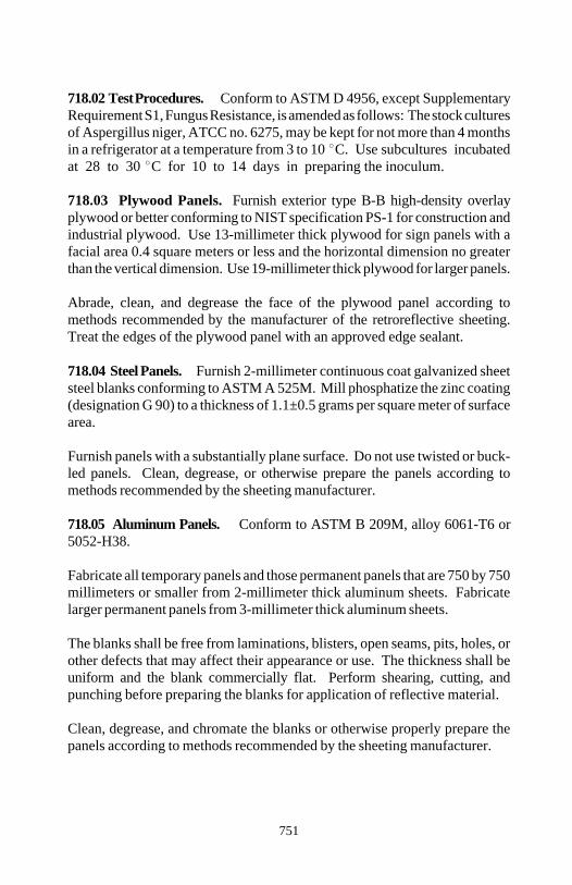
Section 718
751
718.02 Test Procedures. Conform to ASTM D 4956, except SupplementaryRequirement S1, Fungus Resistance, is amended as follows: The stock culturesof Aspergillus niger, ATCC no. 6275, may be kept for not more than 4 monthsin a refrigerator at a temperature from 3 to 10 C. Use subcultures incubatedat 28 to 30 C for 10 to 14 days in preparing the inoculum.
718.03 Plywood Panels. Furnish exterior type B-B high-density overlayplywood or better conforming to NIST specification PS-1 for construction andindustrial plywood. Use 13-millimeter thick plywood for sign panels with afacial area 0.4 square meters or less and the horizontal dimension no greaterthan the vertical dimension. Use 19-millimeter thick plywood for larger panels.
Abrade, clean, and degrease the face of the plywood panel according tomethods recommended by the manufacturer of the retroreflective sheeting.Treat the edges of the plywood panel with an approved edge sealant.
718.04 Steel Panels. Furnish 2-millimeter continuous coat galvanized sheetsteel blanks conforming to ASTM A 525M. Mill phosphatize the zinc coating(designation G 90) to a thickness of 1.1±0.5 grams per square meter of surfacearea.
Furnish panels with a substantially plane surface. Do not use twisted or buck-led panels. Clean, degrease, or otherwise prepare the panels according tomethods recommended by the sheeting manufacturer.
718.05 Aluminum Panels. Conform to ASTM B 209M, alloy 6061-T6 or5052-H38.
Fabricate all temporary panels and those permanent panels that are 750 by 750millimeters or smaller from 2-millimeter thick aluminum sheets. Fabricatelarger permanent panels from 3-millimeter thick aluminum sheets.
The blanks shall be free from laminations, blisters, open seams, pits, holes, orother defects that may affect their appearance or use. The thickness shall beuniform and the blank commercially flat. Perform shearing, cutting, andpunching before preparing the blanks for application of reflective material.
Clean, degrease, and chromate the blanks or otherwise properly prepare thepanels according to methods recommended by the sheeting manufacturer.
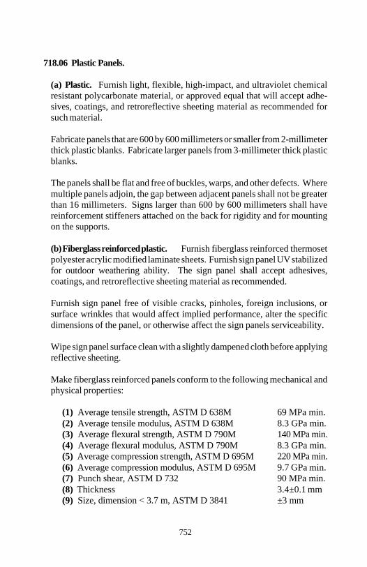
Section 718
752
718.06 Plastic Panels.
(a) Plastic. Furnish light, flexible, high-impact, and ultraviolet chemicalresistant polycarbonate material, or approved equal that will accept adhe-sives, coatings, and retroreflective sheeting material as recommended forsuch material.
Fabricate panels that are 600 by 600 millimeters or smaller from 2-millimeterthick plastic blanks. Fabricate larger panels from 3-millimeter thick plasticblanks.
The panels shall be flat and free of buckles, warps, and other defects. Wheremultiple panels adjoin, the gap between adjacent panels shall not be greaterthan 16 millimeters. Signs larger than 600 by 600 millimeters shall havereinforcement stiffeners attached on the back for rigidity and for mountingon the supports.
(b) Fiberglass reinforced plastic. Furnish fiberglass reinforced thermosetpolyester acrylic modified laminate sheets. Furnish sign panel UV stabilizedfor outdoor weathering ability. The sign panel shall accept adhesives,coatings, and retroreflective sheeting material as recommended.
Furnish sign panel free of visible cracks, pinholes, foreign inclusions, orsurface wrinkles that would affect implied performance, alter the specificdimensions of the panel, or otherwise affect the sign panels serviceability.
Wipe sign panel surface clean with a slightly dampened cloth before applyingreflective sheeting.
Make fiberglass reinforced panels conform to the following mechanical andphysical properties:
(1) Average tensile strength, ASTM D 638M 69 MPa min.(2) Average tensile modulus, ASTM D 638M 8.3 GPa min.(3) Average flexural strength, ASTM D 790M 140 MPa min.(4) Average flexural modulus, ASTM D 790M 8.3 GPa min.(5) Average compression strength, ASTM D 695M 220 MPa min.(6) Average compression modulus, ASTM D 695M 9.7 GPa min.(7) Punch shear, ASTM D 732 90 MPa min.(8) Thickness 3.4±0.1 mm(9) Size, dimension < 3.7 m, ASTM D 3841 ±3 mm

Section 718
753
(10) Squareness in 3.7 m length, ±3 mm ASTM D 3841
(11) Surfaces, top and bottom Smooth(12) Color, visually uniform gray, N.7.5/ - N.8.5/
Munsel rangeR
(13) Coefficient of lineal thermal expansion, 0.01 µm/mm/ C max. ASTM D 696
(14) Impact resistance, -54 to 100 C, 0.54 kg from 18.3 m ASTM D 3841(15) Flame resistance, ASTM D 635 25 mm max.(16) Weather resistance, 3000±100 h, grade II min.
ASTM D 3841
718.07 Extruded Aluminum Panels. Furnish panels conforming to ASTMB 221M aluminum alloy 6063-T6. For panel thickness and fabrication, con-form to Subsection 718.05. The maximum allowable deviation from flat on theface is 4 millimeters per meter.
718.08 Signposts. Furnish wood, steel, or aluminum signposts as speci-fied.
(a) Wood posts. Furnish posts from dry no. 1 grade Douglas fir, southernor Ponderosa pine, hemlock, spruce, or western larch conforming toAASHTO M 168. Treat the posts with water-borne preservative ACA,ACZA, or CCA according to AWPA Standard C14 except the minimumpreservative retention is 6 kilograms per cubic meter.
(b) Steel posts. Furnish posts from billet or rail steel conforming to ASTMA 499. Drill or punch 10-millimeter holes in the posts along the centerlineof the web before galvanizing. Begin punching or drilling 25 millimetersfrom top of post and proceed on 25-millimeter centers for the entire lengthof the post. Galvanize the posts according to ASTM A 123.
(c) Aluminum posts. Furnish approved standard shapes and thicknessesconforming to ASTM B 221M alloy 6061-T6, 6351-T5, 6063-T6, or6005-T5.
718.09 Object Marker and Delineator Posts. Furnish wood, steel, oraluminum object marker and delineator posts. Delineator posts may also befabricated from plastic.

Section 718
754
(a) Wood posts. Furnish 100 by 100-millimeter wooden posts conformingto Subsection 718.08.
(b) Steel posts. Furnish flanged U-channel steel posts weighing not less than3 kilograms per meter and conforming to ASTM A 36M. Galvanize theposts according to ASTM A 123.
(c) Aluminum posts. Furnish standard shaped 3-millimeter thick aluminumposts conforming to ASTM B 221M alloy 356.0-T6.
(d) Plastic posts. Furnish flexible delineator posts made with high impactresistant polymer material.
718.10 Hardware. For lag screws, washers, clip angles, wood screws, shearplates, U-bolts, clamps, bolts, nuts, and other fasteners, use galvanized steel oraluminum alloy.
For high-strength steel bolts, nuts, and washers, conform to Subsection 717.01.Galvanize steel hardware according to ASTM A 153.
For aluminum alloy bolts, nuts, and washers, conform to Subsections 717-.13 and 717.14 as applicable.
Furnish oversize bolt heads and oversize neoprene or nylon washers for plasticsign panels.
718.11 Letters, Numerals, Arrows, Symbols, and Borders. Colors will bespecified in the contract and shall conform to Subsection 718.01.
Form letters, numerals, and other units to provide a continuous stroke widthwith smooth edges. Make the surface flat and free of warp, blisters, wrinkles,burrs, and splinters. Conform to one of the following:
(a) Type L-1 (screen process). Apply letters, numerals, arrows, symbols,and borders on the retroreflective sheeting or opaque background of the signby direct or reverse screen process. Apply messages and borders of a colordarker than the background to the paint or the retroreflective sheeting bydirect process. Produce messages and borders of a color lighter than signbackground by the reverse screen process.
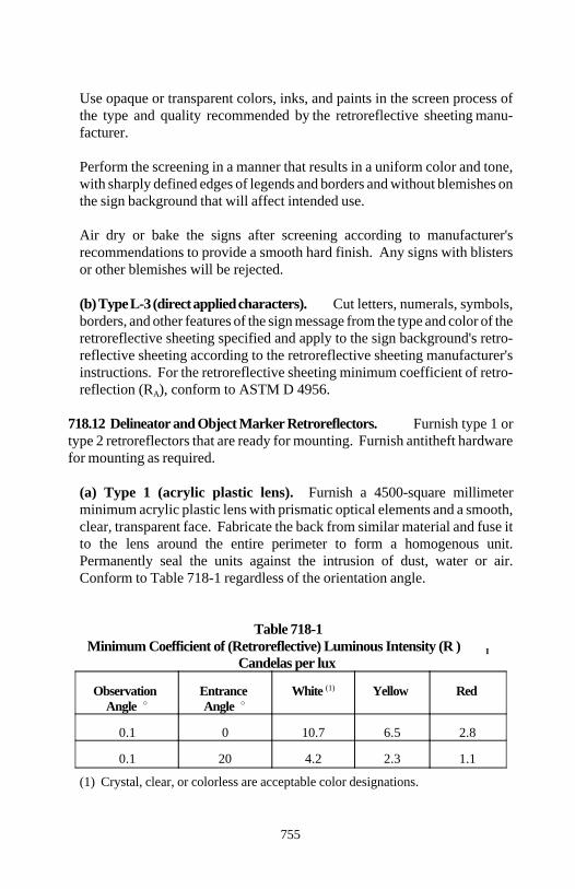
Section 718
755
Use opaque or transparent colors, inks, and paints in the screen process ofthe type and quality recommended by the retroreflective sheeting manu-facturer.
Perform the screening in a manner that results in a uniform color and tone,with sharply defined edges of legends and borders and without blemishes onthe sign background that will affect intended use.
Air dry or bake the signs after screening according to manufacturer'srecommendations to provide a smooth hard finish. Any signs with blistersor other blemishes will be rejected.
(b) Type L-3 (direct applied characters). Cut letters, numerals, symbols,borders, and other features of the sign message from the type and color of theretroreflective sheeting specified and apply to the sign background's retro-reflective sheeting according to the retroreflective sheeting manufacturer'sinstructions. For the retroreflective sheeting minimum coefficient of retro-reflection (R ), conform to ASTM D 4956.A
718.12 Delineator and Object Marker Retroreflectors. Furnish type 1 ortype 2 retroreflectors that are ready for mounting. Furnish antitheft hardwarefor mounting as required.
(a) Type 1 (acrylic plastic lens). Furnish a 4500-square millimeterminimum acrylic plastic lens with prismatic optical elements and a smooth,clear, transparent face. Fabricate the back from similar material and fuse itto the lens around the entire perimeter to form a homogenous unit.Permanently seal the units against the intrusion of dust, water or air.Conform to Table 718-1 regardless of the orientation angle.
Table 718-1Minimum Coefficient of (Retroreflective) Luminous Intensity (R ) I
Candelas per lux
Observation Entrance White Yellow RedAngle Angle
(1)
0.1 0 10.7 6.5 2.8
0.1 20 4.2 2.3 1.1
(1) Crystal, clear, or colorless are acceptable color designations.
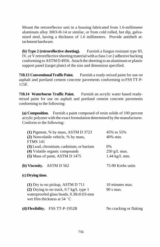
Section 718
756
Mount the retroreflector unit in a housing fabricated from 1.6-millimeteraluminum alloy 3003-H-14 or similar, or from cold rolled, hot dip, galva-nized steel, having a thickness of 1.6 millimeters. Provide antitheft at-tachment hardware.
(b) Type 2 (retroreflective sheeting). Furnish a fungus resistant type III,IV, or V retroreflective sheeting material with a class 1 or 2 adhesive backingconforming to ASTM D 4956. Attach the sheeting to an aluminum or plasticsupport panel (target plate) of the size and dimension specified.
718.13 Conventional Traffic Paint. Furnish a ready-mixed paint for use onasphalt and portland cement concrete pavements conforming to FSS TT-P-115F.
718.14 Waterborne Traffic Paint. Furnish an acrylic water based ready-mixed paint for use on asphalt and portland cement concrete pavementsconforming to the following:
(a) Composition. Furnish a paint composed of resin solids of 100 percentacrylic polymer with the exact formulation determined by the manufacturer.Conform to the following:
(1) Pigment, % by mass, ASTM D 3723 45% to 55%(2) Nonvolatile vehicle, % by mass, 40% min.FTMS 141(3) Lead, chromium, cadmium, or barium 0%(4) Volatile organic compounds 250 g/L max.(5) Mass of paint, ASTM D 1475 1.44 kg/L min.
(b) Viscosity. ASTM D 562 75-90 Krebs units
(c) Drying time.
(1) Dry to no pickup, ASTM D 711 10 minutes max.(2) Drying to no track, 0.7 kg/L type 1 90 s max.waterproofed glass beads, 0.38±0.03-mm wet film thickness at 54 C
(d) Flexibility. FSS TT-P-1952B No cracking or flaking
Section 718
757
(e) Dry opacity. FTMS 141, 0.96 min.contrast ratio at 0.25 mm
(f) Color.
(1) White - FHWA standard highway white(2) Yellow - FHWA standard highway yellow
(g) Daylight reflectance. (Without glass beads)
(1) White, FTMS 141 method 6121 84% relative to magne-sium oxide standard
(2) Yellow, FTMS 141 method 6121 55% relative to magne-sium oxide standard
(h) Bleeding ratio. FSS TT-P-1952B 0.96 min.
(i) Scrub resistance. ASTM D 2486 300 cycles min.
(j) Freeze-thaw stability. FSS TT-P-1952B
(1) Change in viscosity ±5 Krebs units max.(2) Decrease in scrub resistance -10% max.
(k) Storage stability. During a 12 month storage period, conform to thefollowing:
(1) No excessive setting, caking, or increase in viscosity(2) Readily stirred to a consistency for use in the striping equipment
718.15 Epoxy Markings. Furnish a 2-component, 100 percent solids typesystem for hot-spray application conforming to the following:
(a) Pigments. Component A. Percent by mass.
(1) White.
(a) Titanium dioxide (TiO ), ASTM 18% min.2
D 476, type II (16.5% min. at 100% purity)(b) Epoxy resin 75 to 82%
Section 718
758
(2) Yellow:
(a) Chrome yellow (PbCrO ), ASTM 23% min.4
D 211, type III (20% min. at 100% purity)(b) Epoxy resin 70 to 77%
(b) Epoxy content. Component A. Manufacturer's targetMass per epoxy equivalent, ASTM D 1652 value ±50
(c) Amine value. Component B, Manufacturer's targetASTM D 2074 value ±50
(d) Toxicity. Toxic or injurious fumes noneat application temperature
(e) Color. 0.38 millimeter film thickness (cured).
(1) White FHWA standard highway white
(2) Yellow FHWA standard highway yellow
(f) Directional reflectance. (Without glass beads)
(1) White, FTMS 141 method 6121 84% relative to magne-sium oxide standard
(2) Yellow, FTMS 141 method 6121 55% relative to magne-sium oxide standard
(g) Drying time. 0.38 millimeter film thickness with beads
(1) Laboratory at 22 C, ASTM D 711 30 minutes maximum to no-pick-up condition
(2) Field at 25 C, viewed from 15 m 10 minutes maximum to no-tracking condition
(h) Abrasion resistance. Wear index 82 max.with a CS-17 wheel under a 1000 g loadfor 1000 cycles, ASTM C 501
(i) Hardness. Shore D hardness with 72 75 to 100to 96-hour cure at 22 C, ASTM D 2240
Section 718
759
(j) Storage. When stored for up to 12 months, individual epoxy componentsshall not require mixing before use.
718.16 Polyester Markings. Furnish a 2-component system conforming tothe following:
(a) Directional reflectance. (Without glass beads)
(1) White, FTMS 141 method 6121 80% relative to magne-sium oxide standard
(2) Yellow, FTMS 141 method 6121 55% relative to magne-sium oxide standard
(b) Color.
(1) White FHWA standard highway white(2) Yellow FHWA standard highway yellow
(c) Viscosity. Uncatalyzed polyester 70 to 90 Krebs unitsat -4 C, ASTM D 562
(d) Bleeding. ASTM D 969 6 minimum
(e) Drying time in field. Viewed from 15 m 45 minutes max.to no-tracking condition
718.17 Thermoplastic Markings. Conform to AASHTO M 249.
718.18 Preformed Plastic Markings. Conform to ASTM D 4505 type I, V,VI, or VII, grade A, B, C, D, or E.
718.19 Glass Beads. Conform to AASHTO M 247 for the type specified.Table 1, Gradation of Glass Beads in AASHTO M 247 is supplemented byTable 718-2. Treat glass beads with an adherence coating as recommended bymanufacturer.
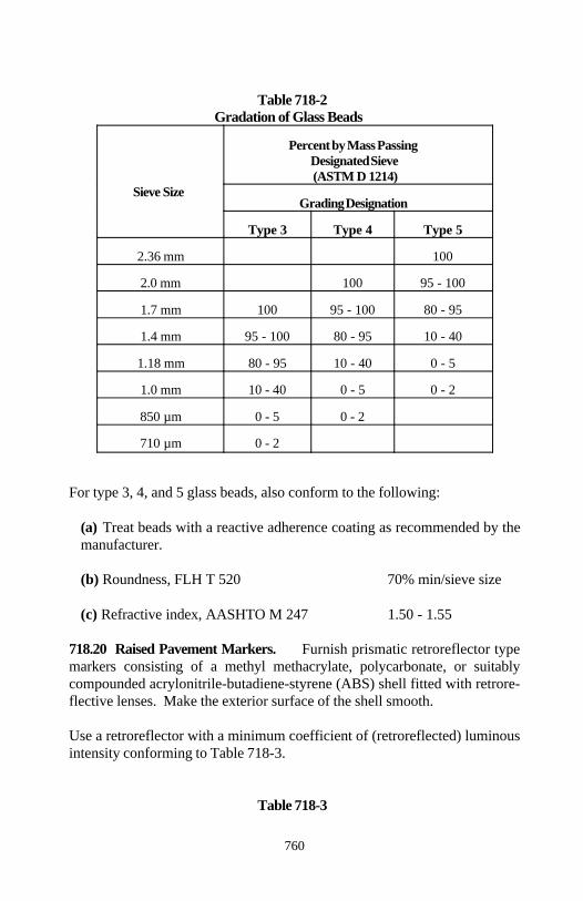
Section 718
760
Table 718-2Gradation of Glass Beads
Sieve Size
Percent by Mass PassingDesignated Sieve(ASTM D 1214)
Grading Designation
Type 3 Type 4 Type 5
2.36 mm 100
2.0 mm 100 95 - 100
1.7 mm 100 95 - 100 80 - 95
1.4 mm 95 - 100 80 - 95 10 - 40
1.18 mm 80 - 95 10 - 40 0 - 5
1.0 mm 10 - 40 0 - 5 0 - 2
850 µm 0 - 5 0 - 2
710 µm 0 - 2
For type 3, 4, and 5 glass beads, also conform to the following:
(a) Treat beads with a reactive adherence coating as recommended by themanufacturer.
(b) Roundness, FLH T 520 70% min/sieve size
(c) Refractive index, AASHTO M 247 1.50 - 1.55
718.20 Raised Pavement Markers. Furnish prismatic retroreflector typemarkers consisting of a methyl methacrylate, polycarbonate, or suitablycompounded acrylonitrile-butadiene-styrene (ABS) shell fitted with retrore-flective lenses. Make the exterior surface of the shell smooth.
Use a retroreflector with a minimum coefficient of (retroreflected) luminousintensity conforming to Table 718-3.
Table 718-3
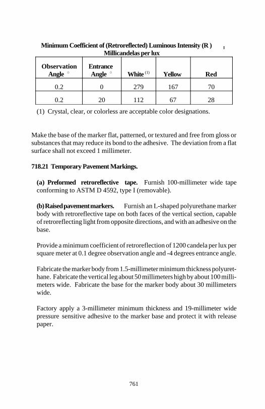
Section 718
761
Minimum Coefficient of (Retroreflected) Luminous Intensity (R ) IMillicandelas per lux
Observation EntranceAngle Angle White Yellow Red(1)
0.2 0 279 167 70
0.2 20 112 67 28
(1) Crystal, clear, or colorless are acceptable color designations.
Make the base of the marker flat, patterned, or textured and free from gloss orsubstances that may reduce its bond to the adhesive. The deviation from a flatsurface shall not exceed 1 millimeter.
718.21 Temporary Pavement Markings.
(a) Preformed retroreflective tape. Furnish 100-millimeter wide tapeconforming to ASTM D 4592, type I (removable).
(b) Raised pavement markers. Furnish an L-shaped polyurethane markerbody with retroreflective tape on both faces of the vertical section, capableof retroreflecting light from opposite directions, and with an adhesive on thebase.
Provide a minimum coefficient of retroreflection of 1200 candela per lux persquare meter at 0.1 degree observation angle and -4 degrees entrance angle.
Fabricate the marker body from 1.5-millimeter minimum thickness polyuret-hane. Fabricate the vertical leg about 50 millimeters high by about 100 milli-meters wide. Fabricate the base for the marker body about 30 millimeterswide.
Factory apply a 3-millimeter minimum thickness and 19-millimeter widepressure sensitive adhesive to the marker base and protect it with releasepaper.

Section 718
762
If approved, variations in design and dimensions will be permitted to meetmanufacturer's standards.
718.22 Temporary Traffic Control Devices. Furnish traffic control devices(barricades, cones, tubular markers, vertical panels, drums, portable barriers,warning lights, advance warning arrow panels, traffic control signals, etc.)whose designs and configurations conform to the MUTCD. When interpretingthe requirements in the applicable MUTCD sections, replace the word "should"with the word "shall."
Use suitable commercial grade material for the fabrication of the temporarytraffic control devices. Construct the devices from material capable ofwithstanding anticipated weather, traffic conditions, and be suitable for theintended use. Do not use units used on other projects without approval. 718.23 Epoxy Resin Adhesives. Epoxy resin adhesives for bonding trafficmarkers to hardened portland cement and asphalt concrete shall conform toAASHTO M 237.
Section 719 Reserved
763
Section 720. ) STRUCTURAL WALL ANDSTABILIZED EMBANKMENT MATERIAL
720.01 Mechanically Stabilized Earth Wall Material.
(a) Concrete face panels. Conform to Section 552 and the following:
(1) Use portland cement concrete class A(AE) with a minimum 30-megapascal, 28-day compressive strength.
(2) Conform to Subsection 562.11 and fully support the units until theconcrete reaches a minimum compressive strength of 7 megapascals. Theunits may be shipped and/or installed after the concrete reaches aminimum compressive strength of 24 megapascals.
(3) Finish the front face of the panel with a class 1 finish according toSubsection 552.16. Screed the rear face of the panel to eliminate openpockets of aggregate and surface distortions in excess of 6 millimeters.Cast the panels on a flat area. Do not attach galvanized connectingdevices or fasteners to the face panel reinforcement steel.
(4) Clearly scribe on an unexposed face of each panel the date ofmanufacture, the production lot number, and the piece mark.
(5) Handle, store, and ship all units in such a manner as to eliminate thedangers of chipping, discoloration, cracks, fractures, and excessivebending stresses. Support panels in storage on firm blocking to protectthe panel connection devices and the exposed exterior finish.
(6) Manufacture all units within the following tolerances:
(a) Panel dimensions. Position of panel connection devices within 25millimeters. All other dimensions within 5 millimeters.
(b) Panel squareness. Squareness, as determined by the differencebetween the 2 diagonals, shall not exceed 13 millimeters.
(c) Panel surface finish. Surface defects on smooth formed surfaces1.5 meters or more in length shall not exceed 3 millimeters. Surfacedefects on textured-finished surfaces 1.5 meters or more in length shallnot exceed 8 millimeters.
Section 720
764
Concrete face panels having any or all of the following defects will be rejec-ted.
Defects that indicate imperfect molding.Defects indicating honeycombed or open texture concrete.Cracked or severely chipped panels.Color variation on front face of panel due to excess form oil or other
reasons.
(b) Wire facing. Fabricate from MW40 x MW15 welded wire fabricconforming to AASHTO M 55M except the average shear value shall not beless than 450 kilopascals. After fabrication, galvanize according toAASHTO M 111.
(c) Backing mat. Fabricate from MW10 x MW10 (minimum) welded wirefabric conforming to AASHTO M 55M. After fabrication, galvanize accord-ing to AASHTO M 111.
(d) Clevis connector. Fabricate from cold-drawn steel wire conforming toAASHTO M 32M and weld according to AASHTO M 55M. Afterfabrication, galvanize according to AASHTO M 111.
(e) Connector bars. Fabricate from cold-drawn steel wire conforming toAASHTO M 32M. Galvanize according to AASHTO M 111.
(f) Fasteners. Furnish 13-millimeter diameter, heavy hexhead bolts, nuts,and washers conforming to AASHTO M 164M. Galvanize according toAASHTO M 232.
(g) Hardware cloth. Fabricate with maximum 7-millimeter square meshopenings from woven or welded galvanized steel wire fabric conforming toASTM A 740.
(h) Reinforcing mesh. Fabricate from cold-drawn steel wire conforming toAASHTO M 32M. Weld the wire into the finished mesh fabric accordingto AASHTO M 55M. After fabrication, galvanize according to AASHTOM 111. Repair all damage to the galvanized coating before installation.
Section 720
765
(i) Reinforcing strips. Fabricate from high-strength low-allow structuralsteel conforming to AASHTO M 223M grade 450, type 3. After fabrication,galvanize according to AASHTO M 111.
(j) Tie strip. Fabricate from hot-rolled steel conforming to ASTM A- 570M grade 50. Galvanize according to AASHTO M 111.
720.02 Gabion and Revet Mattress Material.
(a) Basket mesh. Twist or weld the mesh from galvanized steel wire con-forming to ASTM A 641M class 3 or aluminized steel wire conforming toASTM A 809. Use wire with a minimum tensile strength of 415 megapascalswhen tested according to ASTM A 370. The galvanized or aluminizedcoating may be applied after mesh fabrication. Make the mesh openings witha maximum dimension less than 120 millimeters, an area less than 7000square millimeters, and a size less than the gabion or revet mattress rock tobe used with the mesh.
(1) Gabion baskets (0.3 meter or greater in the vertical dimension).Fabricate the mesh for galvanized or aluminized coated baskets fromnominal-sized 3.0-millimeter or greater diameter wire and fabricate themesh for polyvinyl chloride coated baskets from nominal-sized 2.7-milli-meter or greater diameter wire.
(a) Twisted wire mesh. Form the mesh in a uniform hexagonal patternwith nonraveling double twists. For galvanized or aluminized coatedbaskets, tie the perimeter edges of the mesh for each panel to a 3.9-millimeter or greater diameter selvedge wire. For polyvinyl chloridecoated baskets, tie the perimeter edges of the mesh for each panelto a 3.4-millimeter or greater diameter selvedge wire. Make theselvedge at least the same strength as the body of the mesh. Furnishselvedge wire from the same type of material used for the wire mesh.
(b) Welded wire mesh. For galvanized or aluminized coated baskets,weld each connection to obtain a minimum average weld shearstrength of 2600 newtons with no value less than 2000 newtons. Forpolyvinyl chloride coated baskets, weld each connection to obtain aminimum average weld shear strength of 2100 newtons with no valueless than 1600 newtons.
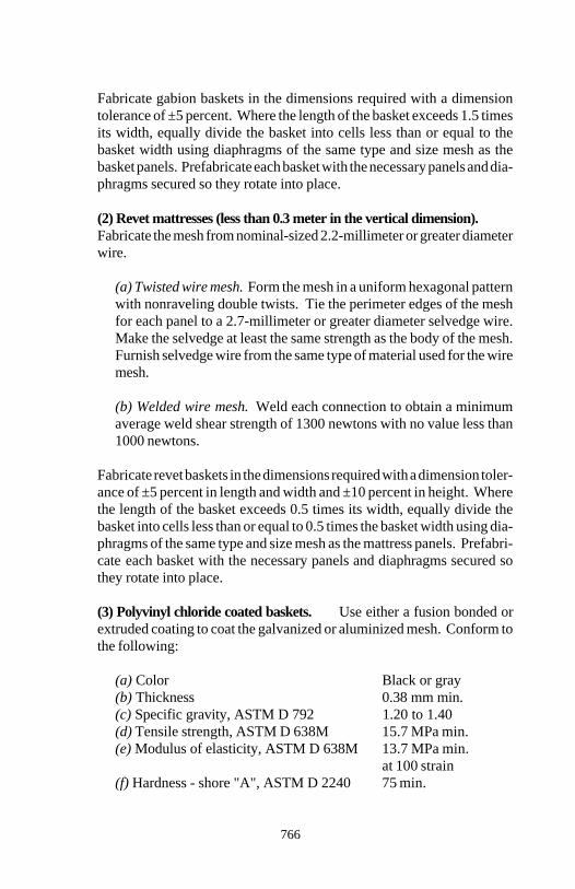
Section 720
766
Fabricate gabion baskets in the dimensions required with a dimensiontolerance of ±5 percent. Where the length of the basket exceeds 1.5 timesits width, equally divide the basket into cells less than or equal to thebasket width using diaphragms of the same type and size mesh as thebasket panels. Prefabricate each basket with the necessary panels and dia-phragms secured so they rotate into place.
(2) Revet mattresses (less than 0.3 meter in the vertical dimension).Fabricate the mesh from nominal-sized 2.2-millimeter or greater diameterwire.
(a) Twisted wire mesh. Form the mesh in a uniform hexagonal patternwith nonraveling double twists. Tie the perimeter edges of the meshfor each panel to a 2.7-millimeter or greater diameter selvedge wire.Make the selvedge at least the same strength as the body of the mesh.Furnish selvedge wire from the same type of material used for the wiremesh.
(b) Welded wire mesh. Weld each connection to obtain a minimumaverage weld shear strength of 1300 newtons with no value less than1000 newtons.
Fabricate revet baskets in the dimensions required with a dimension toler-ance of ±5 percent in length and width and ±10 percent in height. Wherethe length of the basket exceeds 0.5 times its width, equally divide thebasket into cells less than or equal to 0.5 times the basket width using dia-phragms of the same type and size mesh as the mattress panels. Prefabri-cate each basket with the necessary panels and diaphragms secured sothey rotate into place.
(3) Polyvinyl chloride coated baskets. Use either a fusion bonded orextruded coating to coat the galvanized or aluminized mesh. Conform tothe following:
(a) Color Black or gray(b) Thickness 0.38 mm min.(c) Specific gravity, ASTM D 792 1.20 to 1.40(d) Tensile strength, ASTM D 638M 15.7 MPa min.(e) Modulus of elasticity, ASTM D 638M 13.7 MPa min.
at 100 strain(f) Hardness - shore "A", ASTM D 2240 75 min.
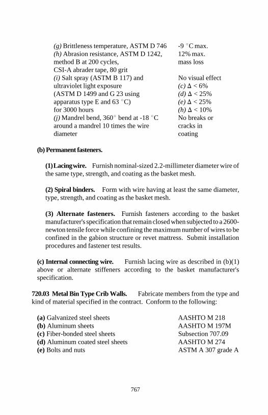
Section 720
767
(g) Brittleness temperature, ASTM D 746 -9 C max.(h) Abrasion resistance, ASTM D 1242, 12% max.method B at 200 cycles, mass lossCSI-A abrader tape, 80 grit(i) Salt spray (ASTM B 117) and No visual effectultraviolet light exposure (c) < 6%(ASTM D 1499 and G 23 using (d) < 25%apparatus type E and 63 C) (e) < 25%for 3000 hours (h) < 10%(j) Mandrel bend, 360 bend at -18 C No breaks oraround a mandrel 10 times the wire cracks indiameter coating
(b) Permanent fasteners.
(1) Lacing wire. Furnish nominal-sized 2.2-millimeter diameter wire ofthe same type, strength, and coating as the basket mesh.
(2) Spiral binders. Form with wire having at least the same diameter,type, strength, and coating as the basket mesh.
(3) Alternate fasteners. Furnish fasteners according to the basketmanufacturer's specification that remain closed when subjected to a 2600-newton tensile force while confining the maximum number of wires to beconfined in the gabion structure or revet mattress. Submit installationprocedures and fastener test results.
(c) Internal connecting wire. Furnish lacing wire as described in (b)(1)above or alternate stiffeners according to the basket manufacturer'sspecification.
720.03 Metal Bin Type Crib Walls. Fabricate members from the type andkind of material specified in the contract. Conform to the following:
(a) Galvanized steel sheets AASHTO M 218(b) Aluminum sheets AASHTO M 197M(c) Fiber-bonded steel sheets Subsection 707.09(d) Aluminum coated steel sheets AASHTO M 274 (e) Bolts and nuts ASTM A 307 grade A

Section 720
768
Furnish heavy hexagon heads and nuts without washers or hexagon heads andnuts with 2 plate washers. Fabricate washers from 3.3-millimeter thick roundsteel plate including coating with holes not more than 1.6 millimeters largerthan the bolt diameter. Galvanize the bolts, nuts, and washers according toAASHTO M 232.
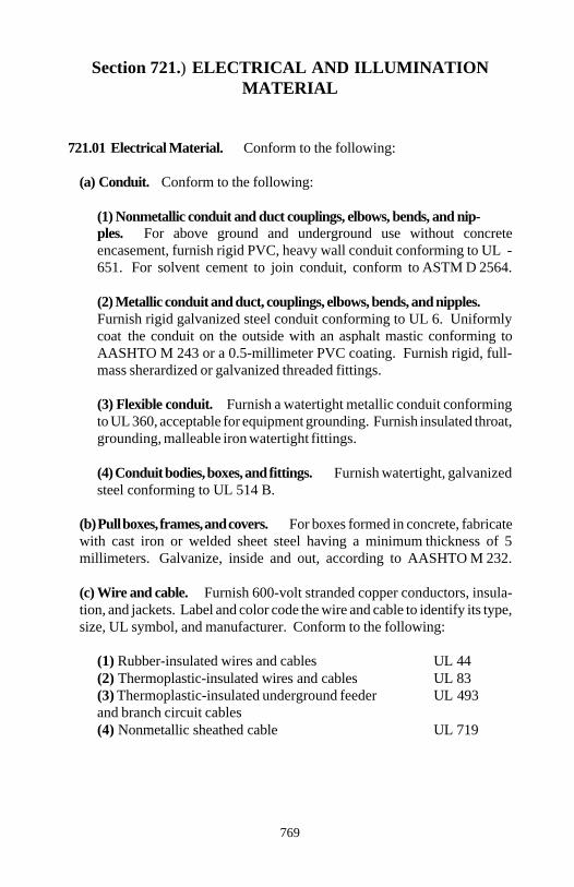
769
Section 721.) ELECTRICAL AND ILLUMINATIONMATERIAL
721.01 Electrical Material. Conform to the following:
(a) Conduit. Conform to the following:
(1) Nonmetallic conduit and duct couplings, elbows, bends, and nip-ples. For above ground and underground use without concreteencasement, furnish rigid PVC, heavy wall conduit conforming to UL -651. For solvent cement to join conduit, conform to ASTM D 2564.
(2) Metallic conduit and duct, couplings, elbows, bends, and nipples.Furnish rigid galvanized steel conduit conforming to UL 6. Uniformlycoat the conduit on the outside with an asphalt mastic conforming toAASHTO M 243 or a 0.5-millimeter PVC coating. Furnish rigid, full-mass sherardized or galvanized threaded fittings.
(3) Flexible conduit. Furnish a watertight metallic conduit conformingto UL 360, acceptable for equipment grounding. Furnish insulated throat,grounding, malleable iron watertight fittings.
(4) Conduit bodies, boxes, and fittings. Furnish watertight, galvanizedsteel conforming to UL 514 B.
(b) Pull boxes, frames, and covers. For boxes formed in concrete, fabricatewith cast iron or welded sheet steel having a minimum thickness of 5millimeters. Galvanize, inside and out, according to AASHTO M 232.
(c) Wire and cable. Furnish 600-volt stranded copper conductors, insula-tion, and jackets. Label and color code the wire and cable to identify its type,size, UL symbol, and manufacturer. Conform to the following:
(1) Rubber-insulated wires and cables UL 44 (2) Thermoplastic-insulated wires and cables UL 83 (3) Thermoplastic-insulated underground feeder UL 493and branch circuit cables(4) Nonmetallic sheathed cable UL 719
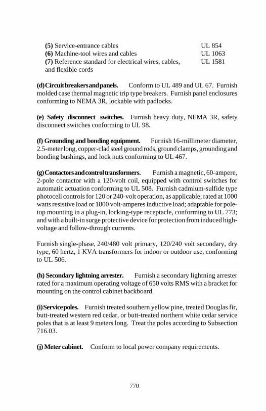
Section 721
770
(5) Service-entrance cables UL 854 (6) Machine-tool wires and cables UL 1063 (7) Reference standard for electrical wires, cables, UL 1581 and flexible cords
(d) Circuit breakers and panels. Conform to UL 489 and UL 67. Furnishmolded case thermal magnetic trip type breakers. Furnish panel enclosuresconforming to NEMA 3R, lockable with padlocks.
(e) Safety disconnect switches. Furnish heavy duty, NEMA 3R, safetydisconnect switches conforming to UL 98.
(f) Grounding and bonding equipment. Furnish 16-millimeter diameter,2.5-meter long, copper-clad steel ground rods, ground clamps, grounding andbonding bushings, and lock nuts conforming to UL 467.
(g) Contactors and control transformers. Furnish a magnetic, 60-ampere,2-pole contactor with a 120-volt coil, equipped with control switches forautomatic actuation conforming to UL 508. Furnish cadmium-sulfide typephotocell controls for 120 or 240-volt operation, as applicable; rated at 1000watts resistive load or 1800 volt-amperes inductive load; adaptable for pole-top mounting in a plug-in, locking-type receptacle, conforming to UL 773;and with a built-in surge protective device for protection from induced high-voltage and follow-through currents.
Furnish single-phase, 240/480 volt primary, 120/240 volt secondary, drytype, 60 hertz, 1 KVA transformers for indoor or outdoor use, conformingto UL 506.
(h) Secondary lightning arrester. Furnish a secondary lightning arresterrated for a maximum operating voltage of 650 volts RMS with a bracket formounting on the control cabinet backboard.
(i) Service poles. Furnish treated southern yellow pine, treated Douglas fir,butt-treated western red cedar, or butt-treated northern white cedar servicepoles that is at least 9 meters long. Treat the poles according to Subsection716.03.
(j) Meter cabinet. Conform to local power company requirements.
Section 721
771
(k) Control cabinet. Furnish a NEMA type IV cabinet, equipped with doorclamps on the unhinged sides, solid neoprene gasket, welded seams,continuous hinge with stainless steel pin, stainless steel external hardware,backboard for mounting apparatus, padlock with an outdoor, tumbler-typepadlocks keyed the same, supplied with 2 keys for each lock. Furnish acabinet constructed of one of the following:
(1) Code-gauge stainless steel, ASTM A 167 type 304(2) Code-gauge aluminum sheet with mechanical properties equivalent orexceeding ASTM B 209 alloy 5052-H32.
721.02 Lighting Material. Conform to the following:
(a) Poles. Furnish 3-millimeter thick round steel conforming to ASTM A595 or aluminum shafts conforming to ASTM B 429 alloy 6063-T6, tapereduniformly at 12 millimeters per meter. Provide hand holes with no roughedges and a reinforcing frame and cover designed to maintain the requiredpole strength. Weld a 60 to 75-millimeter outside diameter vertical tenon,fabricated from the same material as the pole, and welded at the top and onthe same axis as the pole.
Furnish pole sections in minimum 4.5-meter lengths. Furnish pole sectionsless than 21 meters in height in 2 sections or less; between 21 and 30 metersin 3 sections or less; and over 30 meters in 4 sections or less.
Design and furnish poles capable of sustaining the following loadings:
(1) A horizontal load of 2.2 kilonewtons applied 450 millimeters from theshaft top, in any direction, without failure of any component part, and amaximum allowable vertical deflection of 7.5 percent of the shaft length.
(2) A horizontal load of 220 newtons applied at the luminaire attachmentpoint and normal to the pole bracket member plane, with a vertical loadof 130 newtons on the luminaire supporting arm, and a maximumallowable horizontal deflection of 10 percent of the luminaire supportingarm's horizontal length.
(3) A vertical load of 440 newtons applied at the luminaire attachmentpoint, and a maximum allowable vertical deflection of 5.5 percent of thepole arm's horizontal length.
Section 721
772
(4) A vertical load of 1.1 kilonewtons applied at the luminaire attachmentpoint, and no collapse or rupture of any portion of the structure.
(5) The pole arm and luminaire mass with a maximum allowable de-flection from vertical at the top of the pole of 1 percent of the total shaftlength.
Prime the poles inside and out according to the fabricator's recommendation.Use epoxy modified enamel matching FSS 595A color 27040 for the finishcoat.
(b) Pole arms.
(1) Material. Furnish steel or aluminum. Use the same material as thepole.
(2) Type. Furnish bracket type, truss or single member arms. Furnishsingle member arms with a minimum diameter of 50 millimeters and thesame taper as the pole.
(3) Connection. Furnish a weather resistant connection to the pole anda smooth raceway for wiring. Furnish all fittings for connection to thepole.
(c) Anchor bases. Furnish a one-piece base dimensioned for adequate polemounting and structural support with holes for anchor bolts and tapped holesfor anchor bolt covers. Fabricate anchor bases from material similar to thepole material and conform to the following:
(1) Steel casings AASHTO M 103M grade 450-240(2) Steel plate AASHTO M 183M(3) Aluminum castings ASTM B 26M alloy SG70A-T6 (356-T6)
(d) Bolts, nuts, and washers.
(1) Steel anchor bolts. Conform to AASHTO M 183M except asamended by (a) or (b) below:
(a) (1) Yield strength 380 MPa min.(2) Tensile strength 520 to 650 MPa(3) Elongation in 200 mm 18% min.
Section 721
773
(4) Elongation in 50 mm 21% min.(5) Area reduction 30% min.
(b) (1) Yield strength 725 MPa min.(2) Tensile strength 680 to 1030 MPa(3) Elongation in 50 mm 15% min.(4) Area reduction 45% min.
(2) Hex head bolts. Conform to the following:
(a) 380 MPa yield anchor bolts AASHTO M 164M(b) 725 MPa yield anchor bolts ASTM A 354 grade BC
(3) Nuts. Conform to AASHTO M 291M. Furnish nuts appropriate forthe strength of the anchor bolt.
(4) Washers. Furnish flat, circular washers conforming to AASHTO M293.
Galvanize the top 300 millimeters of anchor bolts and all associated hard-ware according to AASHTO M 232.
(e) Anchor bolt covers. Furnish a bolt cover for each anchor bolt and 6-millimeter stainless steel, Phillips-head or hex-head screws to attach thecover to the base or pole.
(f) Luminaires. Operate luminaires on a 240-volt series circuit. Furnish thefollowing types of luminaires.
(1) Conventional highway luminaires. Furnish 250-watt, 100-volt, highpressure sodium vapor lamps including all materials for a completeinstallation. Furnish aluminum housings with refractor holder and slip-fitter. Furnish thermal shock-resistant glass prismatic refractors withgaskets and clips. Furnish aluminum detachable reflectors with ethylenepropylene terpolymer gaskets.
Furnish internal regulator or auto regulator type ballast, with a powerfactor greater than 90 percent, which will start lamps at a minimumambient temperature of -29 C.

Section 721
774
(2) Sign lighting luminaires. Furnish deluxe white, 250-watt mercuryvapor lamps with a minimum rated life of 24 000 hours. Include allmaterial for a complete installation. Furnish die-cast aluminum housingswith mounting bracket and door assembly. Furnish thermal, shock-resis-tant, borosilicate glass refractors with gaskets. Furnish aluminumreflectors.
Furnish 120/240 volt, 60 hertz, constant-wattage ballasts with a powerfactor greater than 90 percent, which will start lamps at a minimumambient temperature of -29 C.
775
Section 722.) ANCHOR MATERIAL
722.01 Anchorage Devices. For post-tensioning, furnish anchorage devic-es capable of holding the prestressing steel at a load producing a stress of notless than 95 percent of the guaranteed minimum tensile strength of the pre-stressing steel.
Use a steel distribution plate or assembly to effectively distribute the com-pressive stresses from the anchoring device to the concrete. If the anchoragedevice is sufficiently large and is used with a steel grillage embedded in theconcrete, the distribution plate or assembly may be omitted. Conform to thefollowing:
(a) The final unit compressive stress on the concrete directly beneath theplate or assembly shall not exceed 21 megapascals.
(b) Bending stresses in the plates or assemblies induced by the pull of theprestressing shall not exceed the yield point of the material or cause visibledistortion in the anchorage plate when 100 percent of the ultimate load isapplied.
Furnish 2 anchorage devices (complete with distribution plates or assemblies)for each size and type to be used.
722.02 Ground Anchors. Conform to the following:
(a) Tendons. For either single or multiple elements, conform to one of thefollowing:
(1) Steel strand uncoated seven-wire stress AASHTO M 203Mrelieved for prestressed concrete
(2) Uncoated high-strength steel bar for AASHTO M 275Mprestressed concrete
(3) Steel strand uncoated seven-wire ASTM A 779 andcompacted stress relieved for AASHTO M 203Mprestressing concrete
Section 722
776
(b) Couplers. Furnish couplers for tendon sections that are capable ofdeveloping 95 percent of the minimum specified ultimate tensile strength ofthe tendon.
(c) Sheathing. Conform to one of the following:
(1) Unbonded length.
(a) Polyethylene tube. Conform to ASTM D 1248 type II, III, or IVwith a minimum wall thickness of 1.5 millimeters.
(b) Hot-melt extruded polypropylene tube. Conform to ASTM D 4101cell classification PP 210 B5554211 with a minimum wall thicknessof 1.5 millimeters.
(c) Hot-melt extruded polyethylene tube. Conform to ASTM D 33-50 and D 1248 high-density type III with a minimum wall thickness of1.5 millimeters.
(d) Steel tubing. Conform to ASTM A 500 with a minimum wallthickness of 5 millimeters.
(e) Steel pipe. Conform to ASTM A 53 schedule 40 minimum.
(f) Plastic pipe. Conform to ASTM D 1785 schedule 40 minimum.
(2) Bonded length.
(a) High-density corrugated polyethylene tubing. Conform toAASHTO M 252 with a minimum wall thickness of 0.75 milli-meters.
(b) Corrugated, polyvinyl chloride tubes. Conform to ASTM D -1784 class 13464-B.
(c) Fusion-bonded epoxy. Conform to AASHTO M 284M with aminimum film thickness of 0.4 millimeters.
(d) Grease. Conform to Table 3.2.1 of the PTI Post Tensioning Manual.Formulate to provide corrosion inhibiting and lubricating properties.
Section 722
777
(e) Grout. Furnish a pumpable mixture of portland cement, sand, water, andadmixtures mixed according to Subsection 725.22. Use type I, II or IIIportland cement conforming to Subsection 701.01.
Chemical additives that control bleed or retard set may be used provided theadditives conform to Subsection 711.03 and are mixed according to themanufacturer's recommendations.
Furnish grout capable of reaching a cube strength (AASHTO T 106) of 25megapascals in 7 days. Make grout cubes for testing from random batchesof grout as directed. Normally, strength testing will not be required assystem performance will be measured by proof-testing each anchor. Groutcube testing will be required if admixtures are used or irregularities occur inanchor testing.
(f) Centralizers. Fabricate centralizers and spacers from any type ofmaterial, except wood, that is not deleterious to the prestressing steel.
(g) Anchorage devices. Conform to Section 3.2.3 of the PTI Post Ten-sioning Manual. For strand tendons, design anchorage devices to permitlift-off testing without the jack engaging the strand. For anchorage devicebearing plates, furnish steel plates conforming to AASHTO M 183M or M222M.
Extend a pipe or trumpet from the anchor plate a sufficient distance toencapsulate the protective sheath. Furnish anchorage devices capable ofdeveloping 95 percent of the minimum specified ultimate tensile strength ofthe anchor tendon.
Sections 723 and 724 Reserved
778
Section 725. ) MISCELLANEOUS MATERIAL
725.01 Water. Conform to the following:
(a) Water for mixing or curing cement concrete, mortar, or grout. Conform to AASHTO M 157. Potable water of known quality may be usedwithout testing according to AASHTO T 26. Potable water is safe for humanconsumption, as defined by the public health authority having jurisdiction.
(b) Water for planting or care of vegetation. Furnish water that is free ofsubstances injurious to plant life such as oils, acids, alkalies, or salts.
(c) Water for earthwork, pavement courses, dust control, and incidentalconstruction. Furnish water free of substances detrimental to the work.
725.02 Calcium Chloride and Magnesium Chloride.
(a) Calcium chloride for dust control. Conform to AASHTO M 144 typeS for the grade and class specified.
(b) Magnesium chloride. Furnish a brine solution conforming to thefollowing:
(1) Magnesium chloride by mass 28 to 35%(2) Water by mass 65 to 72%(3) Specific gravity, ASTM D 1298 1.290 to 1.330
725.03 Lime.
(a) Lime for masonry. Furnish hydrated lime conforming to ASTM C 207type N.
(b) Lime for soil stabilization and paving. Conform to AASHTO M- 216.
725.04 Pozzolans. Conform to the following:
(a) Fly ash AASHTO M 295(b) Ground iron blast-furnace slag AASHTO M 302 grade 100 or 120(c) Silica fume (microsilica) AASHTO M 307
Section 725
779
725.05 Mineral Filler. Conform to AASHTO M 17.
725.06 Precast Concrete Curbing. Furnish units conforming to the fol-lowing:
(a) Concrete Section 601(b) Reinforcing steel Subsection 709.01
725.07 Clay or Shale Brick. Conform to one of the following:
(a) Sewer brick AASHTO M 91 grade SM(b) Building brick AASHTO M 114 grade SW
725.08 Concrete Brick. Conform to ASTM C 55 grade N-I.
725.09 Concrete Masonry Blocks. Furnish rectangular or segmented con-crete masonry blocks. When required, form the block ends to provide aninterlock at vertical joints. Conform to the following:
(a) Solid load-bearing blocks ASTM C 139(b) Hollow load-bearing blocks ASTM C 90(c) Nonload-bearing blocks ASTM C 129
725.10 Cellular Concrete Blocks. Conform to ASTM C 90 grade N-I or N-II, normal mass, except use concrete conforming to Section 601.
725.11 Precast Concrete Units. Cast the units in substantial permanent steelforms. Provide additional reinforcement as necessary to provide for handlingthe units. Use concrete conforming to the following:
(a) 28-day strength, AASHTO T 22 25 MPa min.(b) Air content by volume, when required
(1) 9.5 mm max. size aggregate 5% min.(2) > 9.5 mm max. size aggregate 4% min.
Cure the units according to AASHTO M 170M.
Cast a sufficient number of concrete cylinders from each unit to permitcompression tests at 7, 14 and 28 days. Make at least 3 cylinders for each test.If the strength requirement is met at 7 or 14 days, the units will be certified foruse 14 days from date of casting.
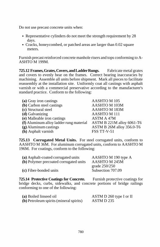
Section 725
780
Do not use precast concrete units when:
Representative cylinders do not meet the strength requirement by 28days.
Cracks, honeycombed, or patched areas are larger than 0.02 squaremeters.
Furnish precast reinforced concrete manhole risers and tops conforming to A-ASHTO M 199M.
725.12 Frames, Grates, Covers, and Ladder Rungs. Fabricate metal gratesand covers to evenly bear on the frames. Correct bearing inaccuracies bymachining. Assemble all units before shipment. Mark all pieces to facilitatereassembly at the installation site. Uniformly coat all castings with asphaltvarnish or with a commercial preservative according to the manufacturer'sstandard practice. Conform to the following:
(a) Gray iron castings AASHTO M 105(b) Carbon steel castings AASHTO M 103M(c) Structural steel AASHTO M 183M(d) Galvanizing AASHTO M 111(e) Malleable iron castings ASTM A 47M(f) Aluminum alloy ladder rung material ASTM B 221M alloy 6061-T6(g) Aluminum castings ASTM B 26M alloy 356.0-T6(h) Asphalt varnish FSS TT-V-51
725.13 Corrugated Metal Units. For steel corrugated units, conform toAASHTO M 36M. For aluminum corrugated units, conform to AASHTO M196M. For coatings, conform to the following:
(a) Asphalt-coated corrugated units AASHTO M 190 type A(b) Polymer precoated corrugated units AASHTO M 245M
grade 250/250(c) Fiber-bonded units Subsection 707.09
725.14 Protective Coatings for Concrete. Furnish protective coatings forbridge decks, curbs, sidewalks, and concrete portions of bridge railingsconforming to one of the following:
(a) Boiled linseed oil ASTM D 260 type I or II(b) Petroleum spirits (mineral spirits) ASTM D 235
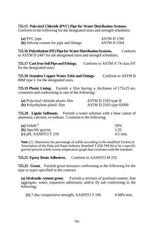
Section 725
781
725.15 Polyvinyl Chloride (PVC) Pipe for Water Distribution Systems.Conform to the following for the designated sizes and strength schedules:
(a) PVC pipe ASTM D 1785(b) Solvent cement for pipe and fittings ASTM D 2564
725.16 Polyethylene (PE) Pipe for Water Distribution Systems. Conformto ASTM D 2447 for the designated sizes and strength schedules.
725.17 Cast Iron Soil Pipe and Fittings. Conform to ASTM A 74 class SVfor the designated sizes.
725.18 Seamless Copper Water Tube and Fittings. Conform to ASTM B88M type L for the designated sizes.
725.19 Plastic Lining. Furnish a film having a thickness of 175±25 mi-crometers and conforming to one of the following:
(a) Polyvinyl chloride plastic film ASTM D 1593 type II(b) Polyethylene plastic film ASTM D 2103 type 02000
725.20 Lignin Sulfonate. Furnish a water solution with a base cation ofammonia, calcium, or sodium. Conform to the following:
(a) Solids 50%(1)
(b) Specific gravity 1.25(c) pH, AASHTO T 210 4.5 min.
Note: (1) Determine the percentage of solids according to the modified TechnicalAssociation of the Pulp and Paper Industry Standard T 650-TM-84 or by a specificgravity/percent solids versus temperature graph that correlates with the standard.
725.21 Epoxy Resin Adhesives. Conform to AASHTO M 235.
725.22 Grout. Furnish grout mixtures conforming to the following for thetype or types specified in the contract.
(a) Hydraulic cement grout. Furnish a mixture of portland cement, fineaggregate, water, expansive admixture, and/or fly ash conforming to thefollowing:
(1) 7-day compressive strength, AASHTO T 106 4 MPa min.
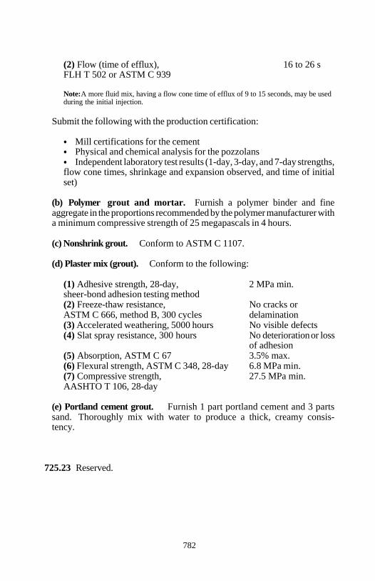
Section 725
782
(2) Flow (time of efflux), 16 to 26 sFLH T 502 or ASTM C 939
Note: A more fluid mix, having a flow cone time of efflux of 9 to 15 seconds, may be usedduring the initial injection.
Submit the following with the production certification:
Mill certifications for the cementPhysical and chemical analysis for the pozzolansIndependent laboratory test results (1-day, 3-day, and 7-day strengths,
flow cone times, shrinkage and expansion observed, and time of initialset)
(b) Polymer grout and mortar. Furnish a polymer binder and fineaggregate in the proportions recommended by the polymer manufacturer witha minimum compressive strength of 25 megapascals in 4 hours.
(c) Nonshrink grout. Conform to ASTM C 1107.
(d) Plaster mix (grout). Conform to the following:
(1) Adhesive strength, 28-day, 2 MPa min.sheer-bond adhesion testing method(2) Freeze-thaw resistance, No cracks orASTM C 666, method B, 300 cycles delamination(3) Accelerated weathering, 5000 hours No visible defects(4) Slat spray resistance, 300 hours No deterioration or loss
of adhesion(5) Absorption, ASTM C 67 3.5% max.(6) Flexural strength, ASTM C 348, 28-day 6.8 MPa min.(7) Compressive strength, 27.5 MPa min.AASHTO T 106, 28-day
(e) Portland cement grout. Furnish 1 part portland cement and 3 partssand. Thoroughly mix with water to produce a thick, creamy consis-tency.
725.23 Reserved.
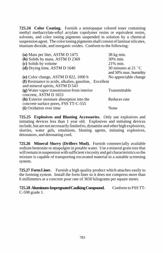
Section 725
783
725.24 Color Coating. Furnish a semiopaque colored toner containingmethyl methacrylate-ethyl acrylate copolymer resins or equivalent resins,solvents, and color toning pigments suspended in solution by a chemicalsuspension agent. The color toning pigments shall consist of laminar silicates,titanium dioxide, and inorganic oxides. Conform to the following:
(a) Mass per liter, ASTM D 1475 38 kg min.(b) Solids by mass, ASTM D 2369 30% min.(c) Solids by volume 21% min.(d) Drying time, ASTM D 1640 30 minutes at 21 C
and 50% max. humidity(e) Color change, ASTM D 822, 1000 h No appreciable change(f) Resistance to acids, alkalies, gasoline, Excellentand mineral spirits, ASTM D 543(g) Water vapor transmission from interior Transmittableconcrete, ASTM D 1653(h) Exterior moisture absorption into the Reduces rateconcrete surface pores, FSS TT-C-555(i) Oxidation over time None
725.25 Explosives and Blasting Accessories. Only use explosives andinitiating devices less than 1 year old. Explosives and initiating devicesinclude, but are not necessarily limited to, dynamite and other high explosives,slurries, water gels, emulsions, blasting agents, initiating explosives,detonators, and detonating cord.
725.26 Mineral Slurry (Drillers Mud). Furnish commercially availablesodium bentonite or attapulgite in potable water. Use a mineral grain size thatwill remain in suspension with sufficient viscosity and gel characteristics so themixture is capable of transporting excavated material to a suitable screeningsystem.
725.27 Form Liner. Furnish a high quality product which attaches easily tothe forming system. Install the form liner so it does not compress more than6 millimeters at a concrete pour rate of 3650 kilograms per square meter.
725.28 Aluminum-Impregnated Caulking Compound. Conform to FSS TT-C-598 grade 1.

785
INDEX
786
) A )
Abbreviations . . . . . . . . . . . . . . . . . . . . . . . . . . . . . . . . . . . . . . . . . . . . . . . . . . 4Acceptance
final . . . . . . . . . . . . . . . . . . . . . . . . . . . . . . . . . . . . . . . . . . . . . . . . . . . . . . . 33of work . . . . . . . . . . . . . . . . . . . . . . . . . . . . . . . . . . . . . . . . . . . . . . . . . . . . 25partial . . . . . . . . . . . . . . . . . . . . . . . . . . . . . . . . . . . . . . . . . . . . . . . . . . . . . 32
Accident prevention . . . . . . . . . . . . . . . . . . . . . . . . . . . . . . . . . . . . . . . . . 42, 84Accident reporting . . . . . . . . . . . . . . . . . . . . . . . . . . . . . . . . . . . . . . . . . . . . . 43Accommodating traffic . . . . . . . . . . . . . . . . . . . . . . . . . . . . . . . . . . . . . . . . . 84Acquisition regulations . . . . . . . . . . . . . . . . . . . . . . . . . . . . . . . . . . . . . . 14, 21Acronyms . . . . . . . . . . . . . . . . . . . . . . . . . . . . . . . . . . . . . . . . . . . . . . . . . . . . . 4Acrylonitrile-butadiene-styrene (ABS) pipe .. . . . . . . . . . . . . . . . . . . . 536, 697Additional clearing and grubbing .. . . . . . . . . . . . . . . . . . . . . . . . . . . . . . . . 102Additives . . . . . . . . . . . . . . . . . . . . . . . . . . . . . . . . . . . . . . . . . . . . . . . 150, 709Administrative change . . . . . . . . . . . . . . . . . . . . . . . . . . . . . . . . . . . . . . . . . . . 8Adhesives . . . . . . . . . . . . . . . . . . . . . . . . . . . . . . . 711, 745, 750, 756, 762, 781Admixtures
air-entraining .. . . . . . . . . . . . . . . . . . . . . . . . . . . . . . . . . . . . . . . . . . . . . . 709chemical . . . . . . . . . . . . . . . . . . . . . . . . . . . . . . . . . . . . . . . . . . . . . . 150, 709
Advance warning arrow panels . . . . . . . . . . . . . . . . . . . . . . . . . . 641, 648, 762Agents . . . . . . . . . . . . . . . . . . . . . . . . . . . . . . . . . . . . . . . . . . . . . . . . . . . . . . 14Aggregate courses
treated . . . . . . . . . . . . . . . . . . . . . . . . . . . . . . . . . . . . . . . . . . . . . . . . . . . . 197untreated . . . . . . . . . . . . . . . . . . . . . . . . . . . . . . . . . . . . . . . . . . . . . . . . . . 192
Aggregate forasphalt surface treatment .. . . . . . . . . . . . . . . . . . . . . . . . . . . . . . . . . . . . . 678base . . . . . . . . . . . . . . . . . . . . . . . . . . . . . . . . . . . . . . . . . . . . . . . . . . . . . . 668bed course . . . . . . . . . . . . . . . . . . . . . . . . . . . . . . . . . . . . . . . . . . . . . . . . . 686blotter . . . . . . . . . . . . . . . . . . . . . . . . . . . . . . . . . . . . . . . . . . . . . . . . . . . . 678choker . . . . . . . . . . . . . . . . . . . . . . . . . . . . . . . . . . . . . . . . . . . . . . . . . . . . 678concrete base course . . . . . . . . . . . . . . . . . . . . . . . . . . . . . . . . . . . . . . . . . 667emulsified asphalt pavement . . . . . . . . . . . . . . . . . . . . . . . . . . . . . . . . . . . 673granular backfill . . . . . . . . . . . . . . . . . . . . . . . . . . . . . . . . . . . . . . . . . . . . 667hot asphalt concrete pavement . . . . . . . . . . . . . . . . . . . . . . . . . . . . . . . . . 671lean concrete backfill . . . . . . . . . . . . . . . . . . . . . . . . . . . . . . . . . . . . . . . . 679open-grade friction course . . . . . . . . . . . . . . . . . . . . . . . . . . . . . . . . . . . . 672portland cement .. . . . . . . . . . . . . . . . . . . . . . . . . . . . . . . . . . . . . . . . . . . . 662select granular backfill . . . . . . . . . . . . . . . . . . . . . . . . . . . . . . . . . . . . . . . 686slurry seal . . . . . . . . . . . . . . . . . . . . . . . . . . . . . . . . . . . . . . . . . . . . . . . . . 677subbase . . . . . . . . . . . . . . . . . . . . . . . . . . . . . . . . . . . . . . . . . . . . . . . . . . . 668surface course . . . . . . . . . . . . . . . . . . . . . . . . . . . . . . . . . . . . . . . . . . . . . . 668topsoil course . . . . . . . . . . . . . . . . . . . . . . . . . . . . . . . . . . . . . . . . . . . . . . 213
787
Aggregate spreader .. . . . . . . . . . . . . . . . . . . . . . . . . . . . . . . . . . . . . . . . . . . 287Aggregate stabilization .. . . . . . . . . . . . . . . . . . . . . . . . . . . . . . . . . . . . . . . . 208Aggregate stockpiled . . . . . . . . . . . . . . . . . . . . . . . . . . . . . . . . . . . . . . . . . . 219Aggregate topsoil course . . . . . . . . . . . . . . . . . . . . . . . . . . . . . . . . . . . . . . . 213Agitators . . . . . . . . . . . . . . . . . . . . . . . . . . . . . . . . . . . . . . . . . . . . . . . . . . . . 376Agricultural limestone . . . . . . . . . . . . . . . . . . . . . . . . . . . . . . . . . . . . . . . . . 716Air compressors . . . . . . . . . . . . . . . . . . . . . . . . . . . . . . . . . . . . . . . . . . 297, 341Air hammers . . . . . . . . . . . . . . . . . . . . . . . . . . . . . . . . . . . . . . . . . . . . . . . . . 355Aluminum alloy
bolt heads and nuts . . . . . . . . . . . . . . . . . . . . . . . . . . . . . . . . . . . . . . . . . . 747bridge rail . . . . . . . . . . . . . . . . . . . . . . . . . . . . . . . . . . . . . . . . . . . . . 453, 747contact surfaces .. . . . . . . . . . . . . . . . . . . . . . . . . . . . . . . . . . . . . . . . . . . . 455corrugated pipe . . . . . . . . . . . . . . . . . . . . . . . . . . . . . . . . . . . . . . . . . 524, 698panels . . . . . . . . . . . . . . . . . . . . . . . . . . . . . . . . . . . . . . . . . . . . 630, 751, 753railing . . . . . . . . . . . . . . . . . . . . . . . . . . . . . . . . . . . . . . . . . . . . . . . . . . . . 454spiral rib pipe . . . . . . . . . . . . . . . . . . . . . . . . . . . . . . . . . . . . . . . . . . 524, 700structural plate structures . . . . . . . . . . . . . . . . . . . . . . . . . . . . . . . . . 528, 699welding wire . . . . . . . . . . . . . . . . . . . . . . . . . . . . . . . . . . . . . . . . . . . . . . . 747
Aluminum-impregnated caulking compound . . . . . . . . . . . . . . . . . . . . . . . . 783Anchor bolts . . . . . . . . . . . . . . . . . . . . . . . . . . . . . . . . . . . . . . . . . . . . . 506, 772Anchors, ground . . . . . . . . . . . . . . . . . . . . . . . . . . . . . . . . . . . . . . . . . . 172, 775Anchorage devices . . . . . . . . . . . . . . . . . . . . . . . . . . . . . . . . . . . . 399, 775, 777Annealing . . . . . . . . . . . . . . . . . . . . . . . . . . . . . . . . . . . . . . . . . . . . . . . . . . . 434Antidesiccant . . . . . . . . . . . . . . . . . . . . . . . . . . . . . . . . . . . . . . . . . . . . . . . . 727Antistrip additive . . . . . . . . . . . . . . . . . . . . . . . . . . . . . . . . . . . . . . . . . 238, 665Apparent specific gravity . . . . . . . . . . . . . . . . . . . . . . . . . . . . . . . . . . . 689, 694Application wand . . . . . . . . . . . . . . . . . . . . . . . . . . . . . . . . . . . . . . . . . . . . . 307Archeological sites . . . . . . . . . . . . . . . . . . . . . . . . . . . . . . . . . . . . . . . . . . . . . 38Arches . . . . . . . . . . . . . . . . . . . . . . . . . . . . . . . . . . . . . . . . . 386, 436, 528, 600Arrows for traffic signs . . . . . . . . . . . . . . . . . . . . . . . . . . . . . . . . . . . . . . . . 754Asphalt
antistrip additive . . . . . . . . . . . . . . . . . . . . . . . . . . . . . . . . . . . . . . . . 238, 665application temperature .. . . . . . . . . . . . . . . . . . . . . . . . . . . . . . . . . . . . . . 664cement . . . . . . . . . . . . . . . . . . . . . . . . . . . . . . . . . . . . . . . . . . . . . 52, 237, 663coated pipe . . . . . . . . . . . . . . . . . . . . . . . . . . . . . . . . . . . . . . . . . . . . 524, 698coated structural plate structures . . . . . . . . . . . . . . . . . . . . . . . . . . . . 528, 699cutback . . . . . . . . . . . . . . . . . . . . . . . . . . . . . . . . . . . . . . . . . . . . . . . . . . . 663distributor . . . . . . . . . . . . . . . . . . . . . . . . . . . . . . . . . . . . . 277, 287, 303, 627emulsified . . . . . . . . . . . . . . . . . . . . . . . . . . . . . . . . . . . . . . . . . . 52, 663, 727evaluation procedures . . . . . . . . . . . . . . . . . . . . . . . . . . . . . . . . . . . . . . . . 665mastic . . . . . . . . . . . . . . . . . . . . . . . . . . . . . . . . . . . . . . . . . . . . . . . . . . . . 665mop coat . . . . . . . . . . . . . . . . . . . . . . . . . . . . . . . . . . . . . . . . . . . . . . . . . . 664paved waterway .. . . . . . . . . . . . . . . . . . . . . . . . . . . . . . . . . . . . . . . . . . . . 546pavement crack and joint sealing . . . . . . . . . . . . . . . . . . . . . . . . . . . . . . . 310
788
Asphalt (continued)pavement milling . . . . . . . . . . . . . . . . . . . . . . . . . . . . . . . . . . . . . . . . . . . 305placement temperature . . . . . . . . . . . . . . . . . . . . . . . . . . . . . . . . . . . . . . . 241plank . . . . . . . . . . . . . . . . . . . . . . . . . . . . . . . . . . . . . . . . . . . . . . . . . 467, 665prime coat . . . . . . . . . . . . . . . . . . . . . . . . . . . . . . . . . . . . . . . . . . . . . . . . . 300recycling agent . . . . . . . . . . . . . . . . . . . . . . . . . . . . . . . . . . . . . . . . . . . . . 665roll roofing . . . . . . . . . . . . . . . . . . . . . . . . . . . . . . . . . . . . . . . . . . . . 467, 665sampling procedures . . . . . . . . . . . . . . . . . . . . . . . . . . . . . . . . . . . . . . . . . 666surface treatment . . . . . . . . . . . . . . . . . . . . . . . . . . . . . . . . . . . . 286, 293, 675tack coat . . . . . . . . . . . . . . . . . . . . . . . . . . . . . . . . . . . . . . . . . . 241, 245, 303
Authority of government inspectors . . . . . . . . . . . . . . . . . . . . . . . . . . . . . . . . . . . . . . . . 20the contracting officer . . . . . . . . . . . . . . . . . . . . . . . . . . . . . . . . . . . . . . . . . 20
Automobile liability insurance . . . . . . . . . . . . . . . . . . . . . . . . . . . . . . . . . . . . 42Award . . . . . . . . . . . . . . . . . . . . . . . . . . . . . . . . . . . . . . . . . . . . . . . 7, 14, 19, 45
) B )
Backer rod . . . . . . . . . . . . . . . . . . . . . . . . . . . . . . . . . . . . . . 332, 344, 652, 712Backfill material . . . . . . . . . . . . . . . . . . . . . . . . . . . . . . . . . . . . . . 132, 138, 684
drainage culvert .. . . . . . . . . . . . . . . . . . . . . . . . . . . . . . . . . . . . 137, 138, 684select granular . . . . . . . . . . . . . . . . . . . . . . . . . . . . . . . . . . . . . . . . . . . . . . 686special grout . . . . . . . . . . . . . . . . . . . . . . . . . . . . . . . . . . . . . . . . . . . . . . . 687structural . . . . . . . . . . . . . . . . . . . . . . . . . . . . . . . . . . . . . . . . . . . . . . . . . . 684
Backing mat . . . . . . . . . . . . . . . . . . . . . . . . . . . . . . . . . . . . . . . . . . . . . . . . . 764Bales . . . . . . . . . . . . . . . . . . . . . . . . . . . . . . . . . . . . . . . . . . . . . . . . . . . . 90, 728Bar chart method . . . . . . . . . . . . . . . . . . . . . . . . . . . . . . . . . . . . . . . . . . . . . . 80Barbed wire . . . . . . . . . . . . . . . . . . . . . . . . . . . . . . . . . . . . . . 586, 590-592, 706Barricades . . . . . . . . . . . . . . . . . . . . . . . . . . . . . . . . . . . . . . . . . . . . 85, 644, 762Base aggregate . . . . . . . . . . . . . . . . . . . . . . . . . . . . . . . . . . . . . . . 192, 226, 668Base course, emulsified asphalt, treated .. . . . . . . . . . . . . . . . . . . . . . . . . . . 226Batching plant . . . . . . . . . . . . . . . . . . . . . . . . . . . . . . . . . . . . . . . . . . . . . . . 376Bearing devices . . . . . . . . . . . . . . . . . . . . . . . . . . . . . . . . . . . . . . . . . . 383, 502
elastomeric pads . . . . . . . . . . . . . . . . . . . . . . . . . . . . . . . . . . . . . . . . . . . . 745masonry, sole, and shim plates . . . . . . . . . . . . . . . . . . . . . . . . . . . . . . . . . 505rocker, roller, and sliding . . . . . . . . . . . . . . . . . . . . . . . . . . . . . . . . . . . . . 504tetrafluoroethylene surfaces . . . . . . . . . . . . . . . . . . . . . . . . . . . . . . . . . . . 745
Bed course . . . . . . . . . . . . . . . . . . . . . . . . . . . . . . . . . . . . . . . . . . . . . . . . . . 686Bedding material . . . . . . . . . . . . . . . . . . . . . . . . . . . . . . . . . . . . . 137, 506, 684Belt conveyor scales . . . . . . . . . . . . . . . . . . . . . . . . . . . . . . . . . . . . . . . . . . . . 52Benching . . . . . . . . . . . . . . . . . . . . . . . . . . . . . . . . . . . . . . . . . . . . . . . 106, 115Bent plates . . . . . . . . . . . . . . . . . . . . . . . . . . . . . . . . . . . . . . . . . . . . . . . . . . 431
789
Bidbond . . . . . . . . . . . . . . . . . . . . . . . . . . . . . . . . . . . . . . . . . . . . . . . . . . . . 7, 15forms . . . . . . . . . . . . . . . . . . . . . . . . . . . . . . . . . . . . . . . . . . . . . . . . . . . . . . . 7guarantee . . . . . . . . . . . . . . . . . . . . . . . . . . . . . . . . . . . . . . . . . . . . . . . . . 7, 15opening of . . . . . . . . . . . . . . . . . . . . . . . . . . . . . . . . . . . . . . . . . . . . . . . . . . 16preparation of . . . . . . . . . . . . . . . . . . . . . . . . . . . . . . . . . . . . . . . . . . . . . . . 14rejection of . . . . . . . . . . . . . . . . . . . . . . . . . . . . . . . . . . . . . . . . . . . . . . . . . 16schedule . . . . . . . . . . . . . . . . . . . . . . . . . . . . . . . . . . . . . . . . . . . . . . . . . . . . 7schedule quantities . . . . . . . . . . . . . . . . . . . . . . . . . . . . . . . . . . . . . . . . . . . 15
Bituminous material . . . . . . . . . . . . . . . . . . . . . . . . . . . . . . . . . . . 467, 710, 711Blasting log . . . . . . . . . . . . . . . . . . . . . . . . . . . . . . . . . . . . . . . . . . . . . . . . . 124Blasting plan . . . . . . . . . . . . . . . . . . . . . . . . . . . . . . . . . . . . . . . . . . . . . . . . 120Block, concrete, masonry, and rubble . . . . . . . . . . . . . . . . . . . . . . . . . 574, 779Blotter . . . . . . . . . . . . . . . . . . . . . . . . . . . . . . . . . . . . . . . . . . . . . . . . . . . . . . 678Bollards . . . . . . . . . . . . . . . . . . . . . . . . . . . . . . . . . . . . . . . . . . . . . . . . 586, 594Bond . . . . . . . . . . . . . . . . . . . . . . . . . . . . . . . . . . . . . . . . . . . . . . . . . . . . . . 7, 16Bonded fiber matrix hydromulch . . . . . . . . . . . . . . . . . . . . . . . . . . . . . . . . . 719Borders for traffic signs . . . . . . . . . . . . . . . . . . . . . . . . . . . . . . . . . . . . . . . . 754Borrow excavation . . . . . . . . . . . . . . . . . . . . . . . . . . . . . . . . . . . . 106, 108, 115Box beam rail . . . . . . . . . . . . . . . . . . . . . . . . . . . . . . . . . . . . . . . . 453, 578, 707Box culverts . . . . . . . . . . . . . . . . . . . . . . . . . . . . . . . . . . . . . . . . . . . . . 386, 524Bracing . . . . . . . . . . . . . . . . . . . . . . . . . . . . . . . . . . . . . . . . . . . . . . . . . . . . . 459Brick . . . . . . . . . . . . . . . . . . . . . . . . . . . . . . . . . . . . . . . . . . . . . . . . . . . . . . . 779Bridge railing . . . . . . . . . . . . . . . . . . . . . . . . . . . . . . . . . . . . 453, 455, 748, 749Bulletin board .. . . . . . . . . . . . . . . . . . . . . . . . . . . . . . . . . . . . . . . . . . . . . . . . 39Burlap . . . . . . . . . . . . . . . . . . . . . . . . . . . . . . . . . . . . . . . . . . . . . . . . . . . . . . 721Burning material .. . . . . . . . . . . . . . . . . . . . . . . . . . . . . . . . . . . . . . . . . . . . . 104Burying material .. . . . . . . . . . . . . . . . . . . . . . . . . . . . . . . . . . . . . . . . . . . . . 104Butyl mastic . . . . . . . . . . . . . . . . . . . . . . . . . . . . . . . . . . . . . . . . . . . . . . . . . 711
) C )
Cable, wire . . . . . . . . . . . . . . . . . . . . . . . . . . . . . . . . . . . . . . . . . . . . . . 578, 704Calcium chloride . . . . . . . . . . . . . . . . . . . . . . . . . . . . . . . . . . . . . . . . . 217, 778Camber diagram . . . . . . . . . . . . . . . . . . . . . . . . . . . . . . . . . . . . . . . . . . . . . . 427Cast iron soil pipe and fittings . . . . . . . . . . . . . . . . . . . . . . . . . . . . . . . 557, 781Castings . . . . . . . . . . . . . . . . . . . . . . . . . . . . . . . . . . . . . . . . . . . . . . . . 744, 780Catch basins . . . . . . . . . . . . . . . . . . . . . . . . . . . . . . . . . . . . . . . . . 104, 531, 533Cattle guards .. . . . . . . . . . . . . . . . . . . . . . . . . . . . . . . . . . . . . . . . . . . . 593,594Caulking compound . . . . . . . . . . . . . . . . . . . . . . . . . . . . . . . . . . . . . . . . . . . 783Cellular concrete blocks . . . . . . . . . . . . . . . . . . . . . . . . . . . . . . . . . . . . 574, 779Cement . . . . . . . . . . . . . . . . . . . . . . . . . . . . . . . . . . . . . . . . . . . . . . . . . . . . . 662Cement rubble masonry . . . . . . . . . . . . . . . . . . . . . . . . . . . . 596, 601, 691, 692Central-mix plant . . . . . . . . . . . . . . . . . . . . . . . . . . . . . . . . . . . . . . . . . 376, 377
790
Centralizers . . . . . . . . . . . . . . . . . . . . . . . . . . . . . . . . . . . . . . . . . . . . . 173, 777Certification . . . . . . . . . . . . . . . . . . . . . . . . . . . . . . . . . . . . . . . . . 26, 27, 59, 75Certification of insurance . . . . . . . . . . . . . . . . . . . . . . . . . . . . . . . . . . . . . . . . 41Chain link fence . . . . . . . . . . . . . . . . . . . . . . . . . . . . . . . . . . . . . . 587, 658, 706Change order . . . . . . . . . . . . . . . . . . . . . . . . . . . . . . . . . . . . . . . . . . . . . . . . . . 8Channel preservation . . . . . . . . . . . . . . . . . . . . . . . . . . . . . . . . . . . . . . 130, 136Check dams . . . . . . . . . . . . . . . . . . . . . . . . . . . . . . . . . . . . . . . . . . . . . . . . . . 91Chemical admixtures . . . . . . . . . . . . . . . . . . . . . . . . . . . . . . . . . . . . . . . . . . 709Choker aggregate . . . . . . . . . . . . . . . . . . . . . . . . . . . . . . . . . . . . . . 277-279, 678Chromium alloy steel castings . . . . . . . . . . . . . . . . . . . . . . . . . . . . . . . . . . . 744Circuit breakers and panels . . . . . . . . . . . . . . . . . . . . . . . . . . . . . . . . . . . . . 770Claims . . . . . . . . . . . . . . . . . . . . . . . . . . . . . . . . . . . . . . . . . . . . . . . 41, 60, 182Clay brick . . . . . . . . . . . . . . . . . . . . . . . . . . . . . . . . . . . . . . . . . . . . . . . 569, 779Clay lumps . . . . . . . . . . . . . . . . . . . . . . . . . . . . . . . . . . . . . . . . . . 671, 673, 676Cleaning drainage structures . . . . . . . . . . . . . . . . . . . . . . . . . . . . . . . . . . . . 543Cleanup . . . . . . . . . . . . . . . . . . . . . . . . . . . . . 92, 123, 245, 261, 276, 277, 701Clearing and grubbing . . . . . . . . . . . . . . . . . . . . . . . . . . . . . . 68, 70-72, 98-102Clevis connector .. . . . . . . . . . . . . . . . . . . . . . . . . . . . . . . . . . . . . . . . . . . . . 764Cloth, hardware . . . . . . . . . . . . . . . . . . . . . . . . . . . . . . . . . . . . . . . . . . . . . . 764Coarse aggregate for portland cement concrete . . . . . . . . . . . . . . . . . . . . . . 667Coconut mat . . . . . . . . . . . . . . . . . . . . . . . . . . . . . . . . . . . . . . . . . . . . . 626, 722Cofferdams . . . . . . . . . . . . . . . . . . . . . . . . . . . . . . . . . . . . . . . . . . . . . . . 21, 130Cold asphalt mix . . . . . . . . . . . . . . . . . . . . . . . . . . . . . . . . . . . . . . . . . 321, 666Cold recycled asphalt base course . . . . . . . . . . . . . . . . . . . . . . . . . . . . 281, 314Cold weather . . . . . . . . . . . . . . . . . . . . . . . . . . . . . . . . . . . . . . . . . . . . . . . . 381Cold-drawn steel wire . . . . . . . . . . . . . . . . . . . . . . . . . . . . . . . . . . . . . 704, 764Cold-poured sealer . . . . . . . . . . . . . . . . . . . . . . . . . . . . . . . . . . . . . . . . . . . . 712Collector systems . . . . . . . . . . . . . . . . . . . . . . . . . . . . . . . . . . . . . . . . . . . . . 556Color coating . . . . . . . . . . . . . . . . . . . . . . . . . . . . . . . . . . . . . . . . . . . . 372, 783Commencement of work . . . . . . . . . . . . . . . . . . . . . . . . . . . . . . . . . . . . . . . . 45Commercial certification . . . . . . . . . . . . . . . . . . . . . . . . . . . . . . . . . . . . . . . . 27Commercial general liability insurance . . . . . . . . . . . . . . . . . . . . . . . . . . . . . 42Completion of work . . . . . . . . . . . . . . . . . . . . . . . . . . . . . . . . . . . . . . . . . . . . 45Compost . . . . . . . . . . . . . . . . . . . . . . . . . . . . . . . . . . . . . . . . . . . . . . . . . . . . 719Comprehensive liability insurance . . . . . . . . . . . . . . . . . . . . . . . . . . . . . . . . . 42Concrete
anchorage devices . . . . . . . . . . . . . . . . . . . . . . . . . . . . . . . . . . . . . . . . . . . 399barriers . . . . . . . . . . . . . . . . . . . . . . . . . . . . . . . . . . . . . . . . . . . . . . . 582, 642bonding . . . . . . . . . . . . . . . . . . . . . . . . . . . . . . . . . . . . . . . . . . . . . . . . . . . 471brick . . . . . . . . . . . . . . . . . . . . . . . . . . . . . . . . . . . . . . . . . . . . . . . . . . . . . 779corrugated steel pipe . . . . . . . . . . . . . . . . . . . . . . . . . . . . . . . . . . . . . 524, 700crib wall . . . . . . . . . . . . . . . . . . . . . . . . . . . . . . . . . . . . . . . . . . . . . . . . . . 165curing material . . . . . . . . . . . . . . . . . . . . . . . . . . . . . . . . . . . . . . . . . . . . . 709finishes . . . . . . . . . . . . . . . . . . . . . . . . . . . . . . . . . . . . . . . . . . . 391, 396, 398
791
Concrete (continued)masonry blocks . . . . . . . . . . . . . . . . . . . . . . . . . . . . . . . . . . . . . . . . . 574, 779minor structures . . . . . . . . . . . . . . . . . . . . . . . . . . . . . . . . . . . . . . . . . . . . 520patching . . . . . . . . . . . . . . . . . . . . . . . . . . . . . . . . . . . . . . . . . . . . . . . . . . . 342pavement aggregate .. . . . . . . . . . . . . . . . . . . . . . . . . . . . . . . . . 232, 671, 679paved waterway .. . . . . . . . . . . . . . . . . . . . . . . . . . . . . . . . . . . . . . . . . . . . 546piles . . . . . . . . . . . . . . . . . . . . . . . . . . . . . . . . . . . . . . . . . . 357, 363, 365, 738pipe . . . . . . . . . . . . . . . . . . . . . . . . . . . . . . . . . . . . . . . . . . . . . . 525, 535, 696prestressed . . . . . . . . . . . . . . . . . . . . . . . . . . . . . . . . . . . . . . . . . . . . . . . . . 404protective coatings . . . . . . . . . . . . . . . . . . . . . . . . . . . . . . . . . . . . . . . . . . 780pumps . . . . . . . . . . . . . . . . . . . . . . . . . . . . . . . . . . . . . . . . . . . . . . . . 388, 508railing . . . . . . . . . . . . . . . . . . . . . . . . . . . . . . . . . . . . . . . . . . . . . . . . . . . . 453railings and parapets . . . . . . . . . . . . . . . . . . . . . . . . . . . . . . . . . . . . . . . . . 389structural . . . . . . . . . . . . . . . . . . . . . . . . . . . . . . . . . . . . . . . . . . . . . . . . . . 372
Cones and tubular markers . . . . . . . . . . . . . . . . . . . . . . . . . . . . . . . . . . . . . . 641Conformity with contract requirements . . . . . . . . . . . . . . . . . . . . . . . . . . . . . 25Connection plates . . . . . . . . . . . . . . . . . . . . . . . . . . . . . . . . . . . . . . . . . . . . . 431Conserved topsoil .. . . . . . . . . . . . . . . . . . . . . . . . . . . . . . . . . . . . 107, 609, 716Construction limits . . . . . . . . . . . . . . . . . . . . . . . . . . . . . . . . . . . . . . . . . . . 7, 38Construction survey and staking . . . . . . . . . . . . . . . . . . . . . . . . . . . . . . . 67, 70Contingent sum . . . . . . . . . . . . . . . . . . . . . . . . . . . . . . . . . . . . . . . . . . . . . . . 15Contract
conformity with .. . . . . . . . . . . . . . . . . . . . . . . . . . . . . . . . . . . . . . . . . . . . . 25coordination of documents . . . . . . . . . . . . . . . . . . . . . . . . . . . . . . . . . . . . . 21intent of . . . . . . . . . . . . . . . . . . . . . . . . . . . . . . . . . . . . . . . . . . . . . . . . . . . . 18modification . . . . . . . . . . . . . . . . . . . . . . . . . . . . . . . . . . . . . . . . . . . 8, 56, 82quantity . . . . . . . . . . . . . . . . . . . . . . . . . . . . . . . . . . . . . . . . . . . . . . 15, 49, 55time . . . . . . . . . . . . . . . . . . . . . . . . . . . . . . . . . . . . . . . . . . . . . . . . . . . . . . . 46
Contracting officer . . . . . . . . . . . . . . . . . . . . . . . . . . . . . . . . . . . . . . . . . . . 8, 20Contractor
material sources . . . . . . . . . . . . . . . . . . . . . . . . . . . . . . . . . . . . . . . . . . . . . 23 quality control . . . . . . . . . . . . . . . . . . . . . . . . . . . . . . . . . . . . . . . . 73, 77, 232records . . . . . . . . . . . . . . . . . . . . . . . . . . . . . . . . . . . . . . . . . . . . . . . . . . . . . 18responsibility for work . . . . . . . . . . . . . . . . . . . . . . . . . . . . . . . . . . . . . . . . 42sampling and testing . . . . . . . . . . . . . . . . . . . . . . . . . . . . . . . . . . . . . . . . . . 77
Control charts . . . . . . . . . . . . . . . . . . . . . . . . . . . . . . . . . . . . . . . . . . . . . . . . . 75Controlled blasting . . . . . . . . . . . . . . . . . . . . . . . . . . . . . . . . . . . . . . . . . . . . 122Conventional traffic paint . . . . . . . . . . . . . . . . . . . . . . . . . . . . . . . . . . . . . . 756Coordination of contract documents . . . . . . . . . . . . . . . . . . . . . . . . . . . . . . . 21Coping . . . . . . . . . . . . . . . . . . . . . . . . . . . . . . . . . . . . . . . . . . . . . . . . . . . . . 599Copper
flashings . . . . . . . . . . . . . . . . . . . . . . . . . . . . . . . . . . . . . . . . . . . . . . . . . . 714water stops . . . . . . . . . . . . . . . . . . . . . . . . . . . . . . . . . . . . . . . . . . . . 469, 714water tube and fittings .. . . . . . . . . . . . . . . . . . . . . . . . . . . . . . . . . . . . . . . 781
Corporations . . . . . . . . . . . . . . . . . . . . . . . . . . . . . . . . . . . . . . . . . . . . . . . . . . 14
792
Corrosion resistant steel rail . . . . . . . . . . . . . . . . . . . . . . . . . . . . . . . . . 578, 707Corrugated
metal spillways . . . . . . . . . . . . . . . . . . . . . . . . . . . . . . . . . . . . . . . . . . . . . 541metal units . . . . . . . . . . . . . . . . . . . . . . . . . . . . . . . . . . . . . . . . . . . . . . . . . 780polyethylene drainage tubing . . . . . . . . . . . . . . . . . . . . . . . . . . . . . . . . . . 697
Cost or pricing data . . . . . . . . . . . . . . . . . . . . . . . . . . . . . . . . . . . . . . . . . . . . 56Countersinking . . . . . . . . . . . . . . . . . . . . . . . . . . . . . . . . . . . . . . . . . . . . . . . 459Crack cleaning and sealing .. . . . . . . . . . . . . . . . . . . . . . . . . . . . . 309, 341, 471Crack fillers . . . . . . . . . . . . . . . . . . . . . . . . . . . . . . . . . . . . . . . . . . . . . . . . . 710Crash cushion barrels . . . . . . . . . . . . . . . . . . . . . . . . . . . . . . . . . . 640, 646, 708Crib wall backfill . . . . . . . . . . . . . . . . . . . . . . . . . . . . . . . . . . . . . . . . . . . . . 688Crib walls . . . . . . . . . . . . . . . . . . . . . . . . . . . . . . . . . . . . . . . . . . . 165, 182, 767Critical path method . . . . . . . . . . . . . . . . . . . . . . . . . . . . . . . . . . . . . . . . . 46, 80Crushed aggregate . . . . . . . . . . . . . . . . . . . . . . . . . . . . . . . . . . . . . . . . . . . . 670Culverts . . . . . . . . . . . . . . . . . . . . . . . . . . . . . . . . . . . . . . . . . . . . 137, 386, 524Curb and gutter .. . . . . . . . . . . . . . . . . . . . . . . . . . . . . . . . . . . . . . . . . . . . . . 550Curbing
asphalt concrete .. . . . . . . . . . . . . . . . . . . . . . . . . . . . . . . . . . . . . . . . . . . . 552cast-in-place concrete . . . . . . . . . . . . . . . . . . . . . . . . . . . . . . . . . . . . . . . . 551precast concrete .. . . . . . . . . . . . . . . . . . . . . . . . . . . . . . . . . . . . . . . . . . . . 550stone . . . . . . . . . . . . . . . . . . . . . . . . . . . . . . . . . . . . . . . . . . . . . . . . . 550, 694
Curing material .. . . . . . . . . . . . . . . . . . . . . . . . . . . . . . . . . . . . . . . . . . . . . . 709Cut-back asphalt .. . . . . . . . . . . . . . . . . . . . . . . . . . . . . . . . . . . . . . . . . . . . . 663
) D )
Damage claims . . . . . . . . . . . . . . . . . . . . . . . . . . . . . . . . . . . . . . . . . . . . . . . . 41Dampproofing . . . . . . . . . . . . . . . . . . . . . . . . . . . . . . . . . . . . . . . . . . . 463, 664Day . . . . . . . . . . . . . . . . . . . . . . . . . . . . . . . . . . . . . . . . . . . . . . . . . . . . . . . . . . 8Default . . . . . . . . . . . . . . . . . . . . . . . . . . . . . . . . . . . . . . . . . . . . . . . . . . . 13, 48Definitions . . . . . . . . . . . . . . . . . . . . . . . . . . . . . . . . . . . . . . . . . 7, 49, 101, 106Deformed steel wire . . . . . . . . . . . . . . . . . . . . . . . . . . . . . . . . . . . . . . . . . . . 704Delineator posts . . . . . . . . . . . . . . . . . . . . . . . . . . . . . . . . . . . . . . . . . . 630, 753Delineator retroreflectors . . . . . . . . . . . . . . . . . . . . . . . . . . . . . . . . . . . . . . . 754Delivery and sampling of concrete . . . . . . . . . . . . . . . . . . . . . . . . . . . . . . . . 380Dense-graded emulsified asphalt pavement . . . . . . . . . . . . . . . . . . . . . . . . . 268Determination of contract time .. . . . . . . . . . . . . . . . . . . . . . . . . . . . . . . . . . . 46Determination of pay factor . . . . . . . . . . . . . . . . . . . . . . . . . . . . . . . . . . . . . . 27Detour . . . . . . . . . . . . . . . . . . . . . . . . . . . . . . . . . . . . . . . . . . . . . . . . . 21, 84, 95Dewatering . . . . . . . . . . . . . . . . . . . . . . . . . . . . . . . . . . . . . . . . . . . . . . 131, 509Diamond grinding . . . . . . . . . . . . . . . . . . . . . . . . . . . . . . . . . . . . 342, 347, 351Diesel hammers . . . . . . . . . . . . . . . . . . . . . . . . . . . . . . . . . . . . . . . . . . 355, 367Dimensioned masonry . . . . . . . . . . . . . . . . . . . . . . . . . . . . . . . . . . . . . 596, 692Direct payment . . . . . . . . . . . . . . . . . . . . . . . . . . . . . . . . . . . . . . . . . . . . . . 3, 54
793
Direct tension indicators .. . . . . . . . . . . . . . . . . . . . . . . . . . . . . . . . . . . 442, 448Disposal of unsuitable material . . . . . . . . . . . . . . . . . . . . . . . . . . 113, 206, 337Disposing of material . . . . . . . . . . . . . . . . . . . . . . . . . . . . . . . . . . . . . . . . . . 104Disputes . . . . . . . . . . . . . . . . . . . . . . . . . . . . . . . . . . . . . . . . . . . . . . . . . . . . . 18Ditches . . . . . . . . . . . . . . . . . . . . . . . . . . . . . . . . . . . . . . . . . 112, 116, 545, 584Dowels . . . . . . . . . . . . . . . . . . . . . . . . . . . . . . . . . 123, 329, 390, 458, 704, 742Drains . . . . . . . . . . . . . . . . . . . . . . . . . . . . . . . . 91, 461, 524, 535, 555, 735-737Drilled shafts . . . . . . . . . . . . . . . . . . . . . . . . . . . . . . . . . . . . . 508-511, 514, 515Drillers mud . . . . . . . . . . . . . . . . . . . . . . . . . . . . . . . . . . . . . . . . . . . . . . . . . 783Drive pads . . . . . . . . . . . . . . . . . . . . . . . . . . . . . . . . . . . . . . . . . . . . . . . 569-571Driven piles . . . . . . . . . . . . . . . . . . . . . . . . . . . . . . . . . . . . . . . . . . . . . 182, 354Drum dryer-mixer plants . . . . . . . . . . . . . . . . . . . . . . . . . . . . . . . . . . . 239, 255Drums . . . . . . . . . . . . . . . . . . . . . . . . . . . . . . . . . . . . . . . . . . . . . . . . . . . . . . 641Ductile iron culvert pipe .. . . . . . . . . . . . . . . . . . . . . . . . . . . . . . . . . . . . . . . 698Ducts . . . . . . . . . . . . . . . . . . . . . . . . . . . . . . . . . . . . . . . . . . . . . . . . . . . . . . 410Durometer hardness . . . . . . . . . . . . . . . . . . . . . . . . . . . . . . . . . . . . . . . . . . . 712Dust control . . . . . . . . . . . . . . . . . . . . . . . . . . . . . . . . . . . . . . . . . . . . . . 95, 778Dust palliative . . . . . . . . . . . . . . . . . . . . . . . . . . . . . . . . . . . . . . . . . . . . 216-218Dynamic formula . . . . . . . . . . . . . . . . . . . . . . . . . . . . . . . . . . . . . . . . . . . . . 361
) E )
Earthwork geotextiles .. . . . . . . . . . . . . . . . . . . . . . . . . . . . . . . . . . . . . . . . . 126Elastomeric bearing pads . . . . . . . . . . . . . . . . . . . . . . . . . . . . . . . . . . . . . . . 745Elastomeric compression joint seals .. . . . . . . . . . . . . . . . . . . . . . . . . . . . . . 747Electrical material .. . . . . . . . . . . . . . . . . . . . . . . . . . . . . . . . . . . . . . . . 652, 769Electrical systems . . . . . . . . . . . . . . . . . . . . . . . . . . . . . . . . . . . . . . . . . . . . . 652Electrochemical requirements
chloride content .. . . . . . . . . . . . . . . . . . . . . . . . . . . . . . . . . . . . . . . . . . . . 687pH . . . . . . . . . . . . . . . . . . . . . . . . . . . . . . . . . . . . . . . . . . . . . . . . . . . . . . . 687resistivity . . . . . . . . . . . . . . . . . . . . . . . . . . . . . . . . . . . . . . . . . . . . . . . . . . 687sulfate content . . . . . . . . . . . . . . . . . . . . . . . . . . . . . . . . . . . . . . . . . . . . . . 687
Eliminated work . . . . . . . . . . . . . . . . . . . . . . . . . . . . . . . . . . . . . . . . . . . . . . . 58Embankment construction . . . . . . . . . . . . . . . . . . . . . . . . . . . . . . 106, 109, 115Emulsified asphalt . . . . . . . . . . . . . . . . . . . . . . . . . . . . . . . . . . . . . 52, 663, 727Emulsified asphalt pavement aggregate . . . . . . . . . . . . . . . . . . . . . . . . 673-675Emulsified asphalt treated base course .. . . . . . . . . . . . . . . . . . . . . . . . . . . . 226Emulsion stabilizers . . . . . . . . . . . . . . . . . . . . . . . . . . . . . . . . . . . . . . . . . . . 709Emulsion tackifiers .. . . . . . . . . . . . . . . . . . . . . . . . . . . . . . . . . . . . . . . 611, 727Environmental protection . . . . . . . . . . . . . . . . . . . . . . . . . . . . . . . . . . . . . . . . 43Epoxy
coated reinforcing steel . . . . . . . . . . . . . . . . . . . . . . . . . . . . . . . 421, 583, 703markings . . . . . . . . . . . . . . . . . . . . . . . . . . . . . . . . . . . . . . . . . . . . . . 636, 757resin adhesives . . . . . . . . . . . . . . . . . . . . . . . . . . . . . . . . . . . . . . . . . 762, 781
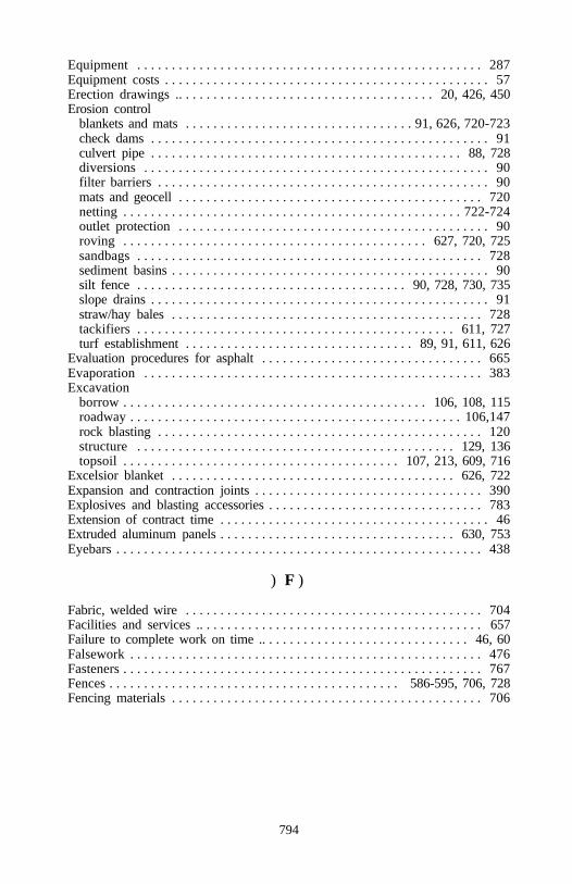
794
Equipment . . . . . . . . . . . . . . . . . . . . . . . . . . . . . . . . . . . . . . . . . . . . . . . . . . 287Equipment costs . . . . . . . . . . . . . . . . . . . . . . . . . . . . . . . . . . . . . . . . . . . . . . . 57Erection drawings .. . . . . . . . . . . . . . . . . . . . . . . . . . . . . . . . . . . . . 20, 426, 450Erosion control
blankets and mats . . . . . . . . . . . . . . . . . . . . . . . . . . . . . . . . . 91, 626, 720-723check dams . . . . . . . . . . . . . . . . . . . . . . . . . . . . . . . . . . . . . . . . . . . . . . . . . 91culvert pipe . . . . . . . . . . . . . . . . . . . . . . . . . . . . . . . . . . . . . . . . . . . . . 88, 728diversions . . . . . . . . . . . . . . . . . . . . . . . . . . . . . . . . . . . . . . . . . . . . . . . . . . 90filter barriers . . . . . . . . . . . . . . . . . . . . . . . . . . . . . . . . . . . . . . . . . . . . . . . . 90mats and geocell . . . . . . . . . . . . . . . . . . . . . . . . . . . . . . . . . . . . . . . . . . . . 720netting . . . . . . . . . . . . . . . . . . . . . . . . . . . . . . . . . . . . . . . . . . . . . . . . . 722-724outlet protection . . . . . . . . . . . . . . . . . . . . . . . . . . . . . . . . . . . . . . . . . . . . . 90roving . . . . . . . . . . . . . . . . . . . . . . . . . . . . . . . . . . . . . . . . . . . . 627, 720, 725sandbags . . . . . . . . . . . . . . . . . . . . . . . . . . . . . . . . . . . . . . . . . . . . . . . . . . 728sediment basins . . . . . . . . . . . . . . . . . . . . . . . . . . . . . . . . . . . . . . . . . . . . . . 90silt fence . . . . . . . . . . . . . . . . . . . . . . . . . . . . . . . . . . . . . . . 90, 728, 730, 735slope drains . . . . . . . . . . . . . . . . . . . . . . . . . . . . . . . . . . . . . . . . . . . . . . . . . 91straw/hay bales . . . . . . . . . . . . . . . . . . . . . . . . . . . . . . . . . . . . . . . . . . . . . 728tackifiers . . . . . . . . . . . . . . . . . . . . . . . . . . . . . . . . . . . . . . . . . . . . . . 611, 727turf establishment . . . . . . . . . . . . . . . . . . . . . . . . . . . . . . . . . 89, 91, 611, 626
Evaluation procedures for asphalt . . . . . . . . . . . . . . . . . . . . . . . . . . . . . . . . 665Evaporation . . . . . . . . . . . . . . . . . . . . . . . . . . . . . . . . . . . . . . . . . . . . . . . . . 383Excavation
borrow . . . . . . . . . . . . . . . . . . . . . . . . . . . . . . . . . . . . . . . . . . . . 106, 108, 115roadway . . . . . . . . . . . . . . . . . . . . . . . . . . . . . . . . . . . . . . . . . . . . . . . . 106,147rock blasting . . . . . . . . . . . . . . . . . . . . . . . . . . . . . . . . . . . . . . . . . . . . . . . 120structure . . . . . . . . . . . . . . . . . . . . . . . . . . . . . . . . . . . . . . . . . . . . . . 129, 136topsoil . . . . . . . . . . . . . . . . . . . . . . . . . . . . . . . . . . . . . . . . 107, 213, 609, 716
Excelsior blanket . . . . . . . . . . . . . . . . . . . . . . . . . . . . . . . . . . . . . . . . . 626, 722Expansion and contraction joints . . . . . . . . . . . . . . . . . . . . . . . . . . . . . . . . . 390Explosives and blasting accessories . . . . . . . . . . . . . . . . . . . . . . . . . . . . . . . 783Extension of contract time . . . . . . . . . . . . . . . . . . . . . . . . . . . . . . . . . . . . . . . 46Extruded aluminum panels . . . . . . . . . . . . . . . . . . . . . . . . . . . . . . . . . . 630, 753Eyebars . . . . . . . . . . . . . . . . . . . . . . . . . . . . . . . . . . . . . . . . . . . . . . . . . . . . . 438
) F )
Fabric, welded wire . . . . . . . . . . . . . . . . . . . . . . . . . . . . . . . . . . . . . . . . . . . 704Facilities and services .. . . . . . . . . . . . . . . . . . . . . . . . . . . . . . . . . . . . . . . . . 657Failure to complete work on time .. . . . . . . . . . . . . . . . . . . . . . . . . . . . . . 46, 60Falsework . . . . . . . . . . . . . . . . . . . . . . . . . . . . . . . . . . . . . . . . . . . . . . . . . . . 476Fasteners . . . . . . . . . . . . . . . . . . . . . . . . . . . . . . . . . . . . . . . . . . . . . . . . . . . . 767Fences . . . . . . . . . . . . . . . . . . . . . . . . . . . . . . . . . . . . . . . . . . 586-595, 706, 728Fencing materials . . . . . . . . . . . . . . . . . . . . . . . . . . . . . . . . . . . . . . . . . . . . . 706
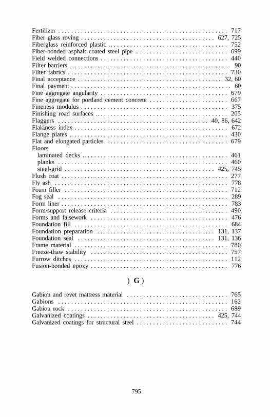
795
Fertilizer . . . . . . . . . . . . . . . . . . . . . . . . . . . . . . . . . . . . . . . . . . . . . . . . . . . . 717Fiber glass roving . . . . . . . . . . . . . . . . . . . . . . . . . . . . . . . . . . . . . . . . . 627, 725Fiberglass reinforced plastic .. . . . . . . . . . . . . . . . . . . . . . . . . . . . . . . . . . . . 752Fiber-bonded asphalt coated steel pipe .. . . . . . . . . . . . . . . . . . . . . . . . . . . . 699Field welded connections . . . . . . . . . . . . . . . . . . . . . . . . . . . . . . . . . . . . . . . 440Filter barriers . . . . . . . . . . . . . . . . . . . . . . . . . . . . . . . . . . . . . . . . . . . . . . . . . 90Filter fabrics . . . . . . . . . . . . . . . . . . . . . . . . . . . . . . . . . . . . . . . . . . . . . . . . . 730Final acceptance . . . . . . . . . . . . . . . . . . . . . . . . . . . . . . . . . . . . . . . . . . . . 32, 60Final payment . . . . . . . . . . . . . . . . . . . . . . . . . . . . . . . . . . . . . . . . . . . . . . . . . 60Fine aggregate angularity . . . . . . . . . . . . . . . . . . . . . . . . . . . . . . . . . . . . . . . 679Fine aggregate for portland cement concrete . . . . . . . . . . . . . . . . . . . . . . . . 667Fineness modulus . . . . . . . . . . . . . . . . . . . . . . . . . . . . . . . . . . . . . . . . . . . . . 375Finishing road surfaces .. . . . . . . . . . . . . . . . . . . . . . . . . . . . . . . . . . . . . . . . 205Flaggers . . . . . . . . . . . . . . . . . . . . . . . . . . . . . . . . . . . . . . . . . . . . . . 40, 86, 642Flakiness index . . . . . . . . . . . . . . . . . . . . . . . . . . . . . . . . . . . . . . . . . . . . . . . 672Flange plates .. . . . . . . . . . . . . . . . . . . . . . . . . . . . . . . . . . . . . . . . . . . . . . . . 430Flat and elongated particles . . . . . . . . . . . . . . . . . . . . . . . . . . . . . . . . . . . . . 679Floors
laminated decks .. . . . . . . . . . . . . . . . . . . . . . . . . . . . . . . . . . . . . . . . . . . . 461planks . . . . . . . . . . . . . . . . . . . . . . . . . . . . . . . . . . . . . . . . . . . . . . . . . . . . 460steel-grid . . . . . . . . . . . . . . . . . . . . . . . . . . . . . . . . . . . . . . . . . . . . . . 425, 745
Flush coat . . . . . . . . . . . . . . . . . . . . . . . . . . . . . . . . . . . . . . . . . . . . . . . . . . . 277Fly ash . . . . . . . . . . . . . . . . . . . . . . . . . . . . . . . . . . . . . . . . . . . . . . . . . . . . . 778Foam filler . . . . . . . . . . . . . . . . . . . . . . . . . . . . . . . . . . . . . . . . . . . . . . . . . . 712Fog seal . . . . . . . . . . . . . . . . . . . . . . . . . . . . . . . . . . . . . . . . . . . . . . . . . . . . 289Form liner . . . . . . . . . . . . . . . . . . . . . . . . . . . . . . . . . . . . . . . . . . . . . . . . . . . 783Form/support release criteria . . . . . . . . . . . . . . . . . . . . . . . . . . . . . . . . . . . . 490Forms and falsework . . . . . . . . . . . . . . . . . . . . . . . . . . . . . . . . . . . . . . . . . . 476Foundation fill . . . . . . . . . . . . . . . . . . . . . . . . . . . . . . . . . . . . . . . . . . . . . . . 684Foundation preparation . . . . . . . . . . . . . . . . . . . . . . . . . . . . . . . . . . . . 131, 137Foundation seal . . . . . . . . . . . . . . . . . . . . . . . . . . . . . . . . . . . . . . . . . . 131, 136Frame material . . . . . . . . . . . . . . . . . . . . . . . . . . . . . . . . . . . . . . . . . . . . . . . 780Freeze-thaw stability . . . . . . . . . . . . . . . . . . . . . . . . . . . . . . . . . . . . . . . . . . 757Furrow ditches . . . . . . . . . . . . . . . . . . . . . . . . . . . . . . . . . . . . . . . . . . . . . . . 112Fusion-bonded epoxy . . . . . . . . . . . . . . . . . . . . . . . . . . . . . . . . . . . . . . . . . . 776
) G )
Gabion and revet mattress material . . . . . . . . . . . . . . . . . . . . . . . . . . . . . . . 765Gabions . . . . . . . . . . . . . . . . . . . . . . . . . . . . . . . . . . . . . . . . . . . . . . . . . . . . 162Gabion rock . . . . . . . . . . . . . . . . . . . . . . . . . . . . . . . . . . . . . . . . . . . . . . . . . 689Galvanized coatings . . . . . . . . . . . . . . . . . . . . . . . . . . . . . . . . . . . . . . . 425, 744Galvanized coatings for structural steel . . . . . . . . . . . . . . . . . . . . . . . . . . . . 744
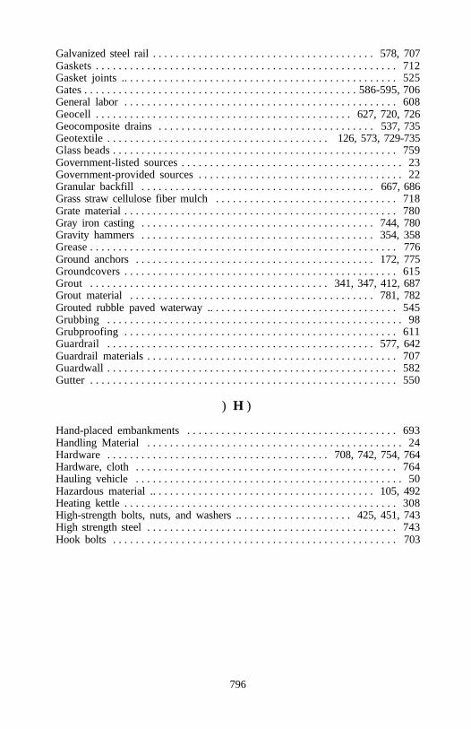
796
Galvanized steel rail . . . . . . . . . . . . . . . . . . . . . . . . . . . . . . . . . . . . . . . 578, 707Gaskets . . . . . . . . . . . . . . . . . . . . . . . . . . . . . . . . . . . . . . . . . . . . . . . . . . . . . 712Gasket joints .. . . . . . . . . . . . . . . . . . . . . . . . . . . . . . . . . . . . . . . . . . . . . . . . 525Gates . . . . . . . . . . . . . . . . . . . . . . . . . . . . . . . . . . . . . . . . . . . . . . . . 586-595, 706General labor . . . . . . . . . . . . . . . . . . . . . . . . . . . . . . . . . . . . . . . . . . . . . . . . 608Geocell . . . . . . . . . . . . . . . . . . . . . . . . . . . . . . . . . . . . . . . . . . . . . 627, 720, 726Geocomposite drains . . . . . . . . . . . . . . . . . . . . . . . . . . . . . . . . . . . . . . 537, 735Geotextile . . . . . . . . . . . . . . . . . . . . . . . . . . . . . . . . . . . . . . . 126, 573, 729-735Glass beads . . . . . . . . . . . . . . . . . . . . . . . . . . . . . . . . . . . . . . . . . . . . . . . . . . 759Government-listed sources . . . . . . . . . . . . . . . . . . . . . . . . . . . . . . . . . . . . . . . 23Government-provided sources . . . . . . . . . . . . . . . . . . . . . . . . . . . . . . . . . . . . 22Granular backfill . . . . . . . . . . . . . . . . . . . . . . . . . . . . . . . . . . . . . . . . . 667, 686Grass straw cellulose fiber mulch . . . . . . . . . . . . . . . . . . . . . . . . . . . . . . . . 718Grate material . . . . . . . . . . . . . . . . . . . . . . . . . . . . . . . . . . . . . . . . . . . . . . . . 780Gray iron casting . . . . . . . . . . . . . . . . . . . . . . . . . . . . . . . . . . . . . . . . . 744, 780Gravity hammers . . . . . . . . . . . . . . . . . . . . . . . . . . . . . . . . . . . . . . . . . 354, 358Grease . . . . . . . . . . . . . . . . . . . . . . . . . . . . . . . . . . . . . . . . . . . . . . . . . . . . . . 776Ground anchors . . . . . . . . . . . . . . . . . . . . . . . . . . . . . . . . . . . . . . . . . . 172, 775Groundcovers . . . . . . . . . . . . . . . . . . . . . . . . . . . . . . . . . . . . . . . . . . . . . . . . 615Grout . . . . . . . . . . . . . . . . . . . . . . . . . . . . . . . . . . . . . . . . . . 341, 347, 412, 687Grout material . . . . . . . . . . . . . . . . . . . . . . . . . . . . . . . . . . . . . . . . . . . 781, 782Grouted rubble paved waterway .. . . . . . . . . . . . . . . . . . . . . . . . . . . . . . . . . 545Grubbing . . . . . . . . . . . . . . . . . . . . . . . . . . . . . . . . . . . . . . . . . . . . . . . . . . . . 98Grubproofing . . . . . . . . . . . . . . . . . . . . . . . . . . . . . . . . . . . . . . . . . . . . . . . . 611Guardrail . . . . . . . . . . . . . . . . . . . . . . . . . . . . . . . . . . . . . . . . . . . . . . . 577, 642Guardrail materials . . . . . . . . . . . . . . . . . . . . . . . . . . . . . . . . . . . . . . . . . . . . 707Guardwall . . . . . . . . . . . . . . . . . . . . . . . . . . . . . . . . . . . . . . . . . . . . . . . . . . . 582Gutter . . . . . . . . . . . . . . . . . . . . . . . . . . . . . . . . . . . . . . . . . . . . . . . . . . . . . . 550
) H )
Hand-placed embankments . . . . . . . . . . . . . . . . . . . . . . . . . . . . . . . . . . . . . 693Handling Material . . . . . . . . . . . . . . . . . . . . . . . . . . . . . . . . . . . . . . . . . . . . . 24Hardware . . . . . . . . . . . . . . . . . . . . . . . . . . . . . . . . . . . . . . . 708, 742, 754, 764Hardware, cloth . . . . . . . . . . . . . . . . . . . . . . . . . . . . . . . . . . . . . . . . . . . . . . 764Hauling vehicle . . . . . . . . . . . . . . . . . . . . . . . . . . . . . . . . . . . . . . . . . . . . . . . 50Hazardous material .. . . . . . . . . . . . . . . . . . . . . . . . . . . . . . . . . . . . . . . 105, 492Heating kettle . . . . . . . . . . . . . . . . . . . . . . . . . . . . . . . . . . . . . . . . . . . . . . . . 308High-strength bolts, nuts, and washers .. . . . . . . . . . . . . . . . . . . . 425, 451, 743High strength steel . . . . . . . . . . . . . . . . . . . . . . . . . . . . . . . . . . . . . . . . . . . . 743Hook bolts . . . . . . . . . . . . . . . . . . . . . . . . . . . . . . . . . . . . . . . . . . . . . . . . . . 703
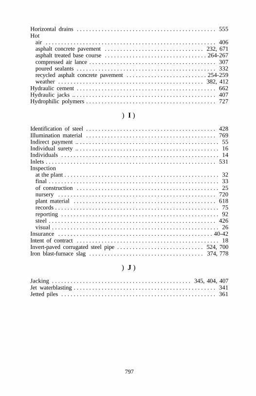
797
Horizontal drains . . . . . . . . . . . . . . . . . . . . . . . . . . . . . . . . . . . . . . . . . . . . . 555Hot
air . . . . . . . . . . . . . . . . . . . . . . . . . . . . . . . . . . . . . . . . . . . . . . . . . . . . . . . 406asphalt concrete pavement . . . . . . . . . . . . . . . . . . . . . . . . . . . . . . . . 232, 671asphalt treated base course . . . . . . . . . . . . . . . . . . . . . . . . . . . . . . . . . 264-267compressed air lance . . . . . . . . . . . . . . . . . . . . . . . . . . . . . . . . . . . . . . . . . 307poured sealants . . . . . . . . . . . . . . . . . . . . . . . . . . . . . . . . . . . . . . . . . . . . . 332recycled asphalt concrete pavement . . . . . . . . . . . . . . . . . . . . . . . . . . 254-259weather . . . . . . . . . . . . . . . . . . . . . . . . . . . . . . . . . . . . . . . . . . . . . . . 382, 412
Hydraulic cement . . . . . . . . . . . . . . . . . . . . . . . . . . . . . . . . . . . . . . . . . . . . . 662Hydraulic jacks .. . . . . . . . . . . . . . . . . . . . . . . . . . . . . . . . . . . . . . . . . . . . . . 407Hydrophilic polymers . . . . . . . . . . . . . . . . . . . . . . . . . . . . . . . . . . . . . . . . . . 727
) I )
Identification of steel . . . . . . . . . . . . . . . . . . . . . . . . . . . . . . . . . . . . . . . . . . 428Illumination material . . . . . . . . . . . . . . . . . . . . . . . . . . . . . . . . . . . . . . . . . . 769Indirect payment .. . . . . . . . . . . . . . . . . . . . . . . . . . . . . . . . . . . . . . . . . . . . . . 55Individual surety .. . . . . . . . . . . . . . . . . . . . . . . . . . . . . . . . . . . . . . . . . . . . . . 16Individuals . . . . . . . . . . . . . . . . . . . . . . . . . . . . . . . . . . . . . . . . . . . . . . . . . . . 14Inlets . . . . . . . . . . . . . . . . . . . . . . . . . . . . . . . . . . . . . . . . . . . . . . . . . . . . . . . 531Inspection
at the plant . . . . . . . . . . . . . . . . . . . . . . . . . . . . . . . . . . . . . . . . . . . . . . . . . . 32final . . . . . . . . . . . . . . . . . . . . . . . . . . . . . . . . . . . . . . . . . . . . . . . . . . . . . . . 33of construction . . . . . . . . . . . . . . . . . . . . . . . . . . . . . . . . . . . . . . . . . . . . . . 25nursery . . . . . . . . . . . . . . . . . . . . . . . . . . . . . . . . . . . . . . . . . . . . . . . . . . . 720plant material . . . . . . . . . . . . . . . . . . . . . . . . . . . . . . . . . . . . . . . . . . . . . . 618records . . . . . . . . . . . . . . . . . . . . . . . . . . . . . . . . . . . . . . . . . . . . . . . . . . . . . 75reporting . . . . . . . . . . . . . . . . . . . . . . . . . . . . . . . . . . . . . . . . . . . . . . . . . . . 92steel . . . . . . . . . . . . . . . . . . . . . . . . . . . . . . . . . . . . . . . . . . . . . . . . . . . . . . 426visual . . . . . . . . . . . . . . . . . . . . . . . . . . . . . . . . . . . . . . . . . . . . . . . . . . . . . . 26
Insurance . . . . . . . . . . . . . . . . . . . . . . . . . . . . . . . . . . . . . . . . . . . . . . . . . . 40-42Intent of contract . . . . . . . . . . . . . . . . . . . . . . . . . . . . . . . . . . . . . . . . . . . . . . 18Invert-paved corrugated steel pipe . . . . . . . . . . . . . . . . . . . . . . . . . . . . 524, 700Iron blast-furnace slag . . . . . . . . . . . . . . . . . . . . . . . . . . . . . . . . . . . . . 374, 778
) J )
Jacking . . . . . . . . . . . . . . . . . . . . . . . . . . . . . . . . . . . . . . . . . . . . . 345, 404, 407Jet waterblasting . . . . . . . . . . . . . . . . . . . . . . . . . . . . . . . . . . . . . . . . . . . . . . 341Jetted piles . . . . . . . . . . . . . . . . . . . . . . . . . . . . . . . . . . . . . . . . . . . . . . . . . . 361
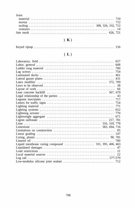
798
Jointmaterial . . . . . . . . . . . . . . . . . . . . . . . . . . . . . . . . . . . . . . . . . . . . . . . . . . . 710mortar . . . . . . . . . . . . . . . . . . . . . . . . . . . . . . . . . . . . . . . . . . . . . . . . . . . . 712sealing . . . . . . . . . . . . . . . . . . . . . . . . . . . . . . . . . . . . . . . . 308, 326, 332, 712ventures . . . . . . . . . . . . . . . . . . . . . . . . . . . . . . . . . . . . . . . . . . . . . . . . . . . . 14
Jute mesh . . . . . . . . . . . . . . . . . . . . . . . . . . . . . . . . . . . . . . . . . . . . . . . 626, 721
) K )
Keyed riprap . . . . . . . . . . . . . . . . . . . . . . . . . . . . . . . . . . . . . . . . . . . . . . . . . 156
) L )
Laboratory, field . . . . . . . . . . . . . . . . . . . . . . . . . . . . . . . . . . . . . . . . . . . . . . 657Labor, general .. . . . . . . . . . . . . . . . . . . . . . . . . . . . . . . . . . . . . . . . . . . . . . . 608Ladder rung material . . . . . . . . . . . . . . . . . . . . . . . . . . . . . . . . . . . . . . . . . . 780Lag screws . . . . . . . . . . . . . . . . . . . . . . . . . . . . . . . . . . . . . . . . . . . . . . . . . . 754Laminated decks .. . . . . . . . . . . . . . . . . . . . . . . . . . . . . . . . . . . . . . . . . . . . . 461Lateral gusset plates . . . . . . . . . . . . . . . . . . . . . . . . . . . . . . . . . . . . . . . . . . . 431Latex modifier . . . . . . . . . . . . . . . . . . . . . . . . . . . . . . . . . . . . . . . . . . . 372, 709Laws to be observed . . . . . . . . . . . . . . . . . . . . . . . . . . . . . . . . . . . . . . . . . . . . 38Layout of work . . . . . . . . . . . . . . . . . . . . . . . . . . . . . . . . . . . . . . . . . . . . . . . . 66Lean concrete backfill . . . . . . . . . . . . . . . . . . . . . . . . . . . . . . . . . . . . . 567, 679Legal relationship of the parties . . . . . . . . . . . . . . . . . . . . . . . . . . . . . . . . . . . 43Legume inoculants . . . . . . . . . . . . . . . . . . . . . . . . . . . . . . . . . . . . . . . . . . . . 717Letters for traffic signs . . . . . . . . . . . . . . . . . . . . . . . . . . . . . . . . . . . . . . . . . 754Lighting material . . . . . . . . . . . . . . . . . . . . . . . . . . . . . . . . . . . . . . . . . . . . . 771Lighting systems .. . . . . . . . . . . . . . . . . . . . . . . . . . . . . . . . . . . . . . . . . . . . . 652Lightning arrester . . . . . . . . . . . . . . . . . . . . . . . . . . . . . . . . . . . . . . . . . . . . . 770Lightweight aggregate . . . . . . . . . . . . . . . . . . . . . . . . . . . . . . . . . . . . . . . . . 671Lignin sulfonate . . . . . . . . . . . . . . . . . . . . . . . . . . . . . . . . . . . . . . . . . . 217, 781Lime . . . . . . . . . . . . . . . . . . . . . . . . . . . . . . . . . . . . . . . . . . . . . . . 316, 318, 778Limestone . . . . . . . . . . . . . . . . . . . . . . . . . . . . . . . . . . . . . . . . . . . 583, 694, 716Limitations on construction . . . . . . . . . . . . . . . . . . . . . . . . . . . . . . . . . . . . . . 85Linear grading . . . . . . . . . . . . . . . . . . . . . . . . . . . . . . . . . . . . . . . . . . . . . . . 147Lining, plastic .. . . . . . . . . . . . . . . . . . . . . . . . . . . . . . . . . . . . . . . . . . . . 90, 781Linseed oil . . . . . . . . . . . . . . . . . . . . . . . . . . . . . . . . . . . . . . . . . . . . . . . . . . 780Liquid membrane curing compound . . . . . . . . . . . . . . . . . . 331, 395, 406, 463Liquidated damages . . . . . . . . . . . . . . . . . . . . . . . . . . . . . . . . . . . . . . . . . . . . 47Load restrictions . . . . . . . . . . . . . . . . . . . . . . . . . . . . . . . . . . . . . . . . . . . . . . . 21Local material sources . . . . . . . . . . . . . . . . . . . . . . . . . . . . . . . . . . . . . . . . . . 22Log rail . . . . . . . . . . . . . . . . . . . . . . . . . . . . . . . . . . . . . . . . . . . . . . . . . . 577-579Low-modulus silicone joint sealant . . . . . . . . . . . . . . . . . . . . . . . . . . . . . . . 712
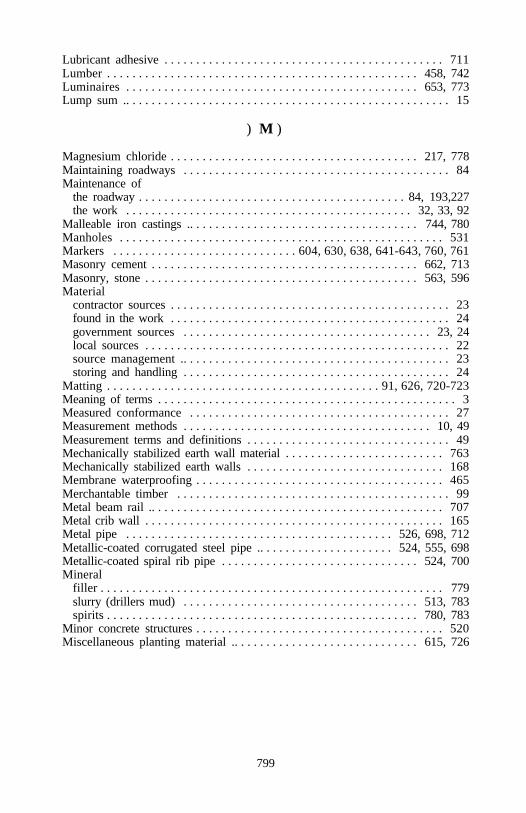
799
Lubricant adhesive . . . . . . . . . . . . . . . . . . . . . . . . . . . . . . . . . . . . . . . . . . . . 711Lumber . . . . . . . . . . . . . . . . . . . . . . . . . . . . . . . . . . . . . . . . . . . . . . . . . 458, 742Luminaires . . . . . . . . . . . . . . . . . . . . . . . . . . . . . . . . . . . . . . . . . . . . . . 653, 773Lump sum .. . . . . . . . . . . . . . . . . . . . . . . . . . . . . . . . . . . . . . . . . . . . . . . . . . . 15
) M )
Magnesium chloride . . . . . . . . . . . . . . . . . . . . . . . . . . . . . . . . . . . . . . . 217, 778Maintaining roadways . . . . . . . . . . . . . . . . . . . . . . . . . . . . . . . . . . . . . . . . . . 84Maintenance of
the roadway . . . . . . . . . . . . . . . . . . . . . . . . . . . . . . . . . . . . . . . . . . 84, 193,227the work . . . . . . . . . . . . . . . . . . . . . . . . . . . . . . . . . . . . . . . . . . . . . 32, 33, 92
Malleable iron castings .. . . . . . . . . . . . . . . . . . . . . . . . . . . . . . . . . . . . 744, 780Manholes . . . . . . . . . . . . . . . . . . . . . . . . . . . . . . . . . . . . . . . . . . . . . . . . . . . 531Markers . . . . . . . . . . . . . . . . . . . . . . . . . . . . . 604, 630, 638, 641-643, 760, 761Masonry cement . . . . . . . . . . . . . . . . . . . . . . . . . . . . . . . . . . . . . . . . . . 662, 713Masonry, stone . . . . . . . . . . . . . . . . . . . . . . . . . . . . . . . . . . . . . . . . . . . 563, 596Material
contractor sources . . . . . . . . . . . . . . . . . . . . . . . . . . . . . . . . . . . . . . . . . . . . 23found in the work . . . . . . . . . . . . . . . . . . . . . . . . . . . . . . . . . . . . . . . . . . . . 24government sources . . . . . . . . . . . . . . . . . . . . . . . . . . . . . . . . . . . . . . . 23, 24local sources . . . . . . . . . . . . . . . . . . . . . . . . . . . . . . . . . . . . . . . . . . . . . . . . 22source management .. . . . . . . . . . . . . . . . . . . . . . . . . . . . . . . . . . . . . . . . . . 23storing and handling . . . . . . . . . . . . . . . . . . . . . . . . . . . . . . . . . . . . . . . . . . 24
Matting . . . . . . . . . . . . . . . . . . . . . . . . . . . . . . . . . . . . . . . . . . . 91, 626, 720-723Meaning of terms . . . . . . . . . . . . . . . . . . . . . . . . . . . . . . . . . . . . . . . . . . . . . . . 3Measured conformance . . . . . . . . . . . . . . . . . . . . . . . . . . . . . . . . . . . . . . . . . 27Measurement methods . . . . . . . . . . . . . . . . . . . . . . . . . . . . . . . . . . . . . . . 10, 49Measurement terms and definitions . . . . . . . . . . . . . . . . . . . . . . . . . . . . . . . . 49Mechanically stabilized earth wall material . . . . . . . . . . . . . . . . . . . . . . . . . 763Mechanically stabilized earth walls . . . . . . . . . . . . . . . . . . . . . . . . . . . . . . . 168Membrane waterproofing . . . . . . . . . . . . . . . . . . . . . . . . . . . . . . . . . . . . . . . 465Merchantable timber . . . . . . . . . . . . . . . . . . . . . . . . . . . . . . . . . . . . . . . . . . . 99Metal beam rail .. . . . . . . . . . . . . . . . . . . . . . . . . . . . . . . . . . . . . . . . . . . . . . 707Metal crib wall . . . . . . . . . . . . . . . . . . . . . . . . . . . . . . . . . . . . . . . . . . . . . . . 165Metal pipe . . . . . . . . . . . . . . . . . . . . . . . . . . . . . . . . . . . . . . . . . . 526, 698, 712Metallic-coated corrugated steel pipe .. . . . . . . . . . . . . . . . . . . . . 524, 555, 698Metallic-coated spiral rib pipe . . . . . . . . . . . . . . . . . . . . . . . . . . . . . . . 524, 700Mineral
filler . . . . . . . . . . . . . . . . . . . . . . . . . . . . . . . . . . . . . . . . . . . . . . . . . . . . . . 779slurry (drillers mud) . . . . . . . . . . . . . . . . . . . . . . . . . . . . . . . . . . . . . 513, 783spirits . . . . . . . . . . . . . . . . . . . . . . . . . . . . . . . . . . . . . . . . . . . . . . . . . 780, 783
Minor concrete structures . . . . . . . . . . . . . . . . . . . . . . . . . . . . . . . . . . . . . . . 520Miscellaneous planting material .. . . . . . . . . . . . . . . . . . . . . . . . . . . . . 615, 726
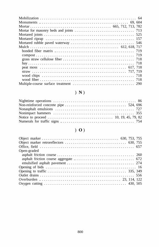
800
Mobilization . . . . . . . . . . . . . . . . . . . . . . . . . . . . . . . . . . . . . . . . . . . . . . . . . . 64Monuments .. . . . . . . . . . . . . . . . . . . . . . . . . . . . . . . . . . . . . . . . . . . . . . 69, 604Mortar . . . . . . . . . . . . . . . . . . . . . . . . . . . . . . . . . . . . . . . . . . 665, 712, 713, 782Mortar for masonry beds and joints . . . . . . . . . . . . . . . . . . . . . . . . . . . . . . . 713Mortared joints . . . . . . . . . . . . . . . . . . . . . . . . . . . . . . . . . . . . . . . . . . . . . . . 525Mortared riprap . . . . . . . . . . . . . . . . . . . . . . . . . . . . . . . . . . . . . . . . . . . . . . 157Mortared rubble paved waterway . . . . . . . . . . . . . . . . . . . . . . . . . . . . . . . . . 546Mulch . . . . . . . . . . . . . . . . . . . . . . . . . . . . . . . . . . . . . . . . . . . . . . 612, 618, 717
bonded fiber matrix .. . . . . . . . . . . . . . . . . . . . . . . . . . . . . . . . . . . . . . . . . 719compost . . . . . . . . . . . . . . . . . . . . . . . . . . . . . . . . . . . . . . . . . . . . . . . . . . . 719grass straw cellulose fiber . . . . . . . . . . . . . . . . . . . . . . . . . . . . . . . . . . . . . 718hay . . . . . . . . . . . . . . . . . . . . . . . . . . . . . . . . . . . . . . . . . . . . . . . . . . . . . . . 718peat moss . . . . . . . . . . . . . . . . . . . . . . . . . . . . . . . . . . . . . . . . . . . . . 617, 718straw . . . . . . . . . . . . . . . . . . . . . . . . . . . . . . . . . . . . . . . . . . . . . . . . . 717, 719wood chips . . . . . . . . . . . . . . . . . . . . . . . . . . . . . . . . . . . . . . . . . . . . . . . . 718wood fiber . . . . . . . . . . . . . . . . . . . . . . . . . . . . . . . . . . . . . . . . . . . . . . . . . 718
Multiple-course surface treatment . . . . . . . . . . . . . . . . . . . . . . . . . . . . . . . . 290
) N )
Nighttime operations . . . . . . . . . . . . . . . . . . . . . . . . . . . . . . . . . . . . . . . . . . . 86Non-reinforced concrete pipe . . . . . . . . . . . . . . . . . . . . . . . . . . . . . . . . 524, 696Nonasphalt emulsions . . . . . . . . . . . . . . . . . . . . . . . . . . . . . . . . . . . . . . . . . 727Nonimpact hammers . . . . . . . . . . . . . . . . . . . . . . . . . . . . . . . . . . . . . . . . . . 355Notice to proceed . . . . . . . . . . . . . . . . . . . . . . . . . . . . . . . . . . 10, 19, 45, 79, 82Numerals for traffic signs .. . . . . . . . . . . . . . . . . . . . . . . . . . . . . . . . . . . . . . 754
) O )
Object marker . . . . . . . . . . . . . . . . . . . . . . . . . . . . . . . . . . . . . . . . 630, 753, 755Object marker retroreflectors . . . . . . . . . . . . . . . . . . . . . . . . . . . . . . . . 630, 755Office, field . . . . . . . . . . . . . . . . . . . . . . . . . . . . . . . . . . . . . . . . . . . . . . . . . 657Open-graded
asphalt friction course . . . . . . . . . . . . . . . . . . . . . . . . . . . . . . . . . . . . . . . . 260asphalt friction course aggregate .. . . . . . . . . . . . . . . . . . . . . . . . . . . . . . . 672emulsified asphalt pavement . . . . . . . . . . . . . . . . . . . . . . . . . . . . . . . . . . . 274
Opening of bids . . . . . . . . . . . . . . . . . . . . . . . . . . . . . . . . . . . . . . . . . . . . . . . 16Opening to traffic . . . . . . . . . . . . . . . . . . . . . . . . . . . . . . . . . . . . . . . . . 335, 349Outlet drains . . . . . . . . . . . . . . . . . . . . . . . . . . . . . . . . . . . . . . . . . . . . . . . . . 556Overburden .. . . . . . . . . . . . . . . . . . . . . . . . . . . . . . . . . . . . . . . . . . 23, 114, 122Oxygen cutting . . . . . . . . . . . . . . . . . . . . . . . . . . . . . . . . . . . . . . . . . . . 430, 505
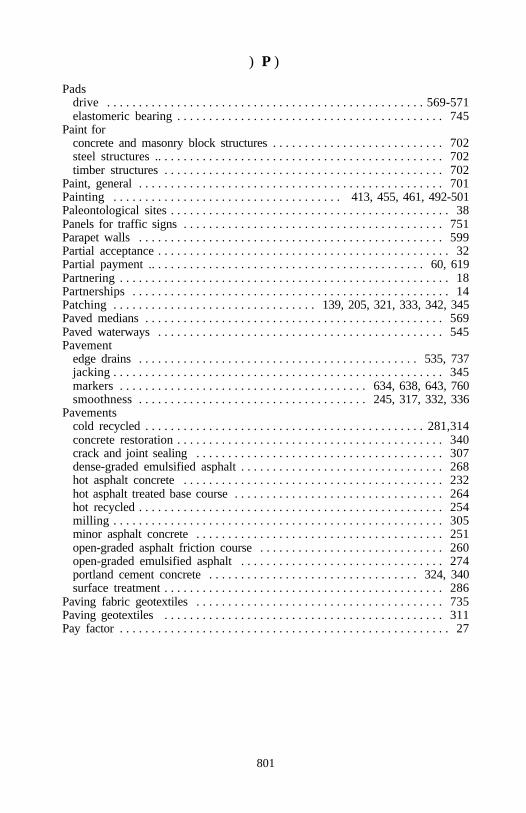
801
) P )
Padsdrive . . . . . . . . . . . . . . . . . . . . . . . . . . . . . . . . . . . . . . . . . . . . . . . . . . 569-571elastomeric bearing . . . . . . . . . . . . . . . . . . . . . . . . . . . . . . . . . . . . . . . . . . 745
Paint for concrete and masonry block structures . . . . . . . . . . . . . . . . . . . . . . . . . . . 702steel structures .. . . . . . . . . . . . . . . . . . . . . . . . . . . . . . . . . . . . . . . . . . . . . 702timber structures . . . . . . . . . . . . . . . . . . . . . . . . . . . . . . . . . . . . . . . . . . . . 702
Paint, general . . . . . . . . . . . . . . . . . . . . . . . . . . . . . . . . . . . . . . . . . . . . . . . . 701Painting . . . . . . . . . . . . . . . . . . . . . . . . . . . . . . . . . . . . 413, 455, 461, 492-501Paleontological sites . . . . . . . . . . . . . . . . . . . . . . . . . . . . . . . . . . . . . . . . . . . . 38Panels for traffic signs . . . . . . . . . . . . . . . . . . . . . . . . . . . . . . . . . . . . . . . . . 751Parapet walls . . . . . . . . . . . . . . . . . . . . . . . . . . . . . . . . . . . . . . . . . . . . . . . . 599Partial acceptance . . . . . . . . . . . . . . . . . . . . . . . . . . . . . . . . . . . . . . . . . . . . . . 32Partial payment .. . . . . . . . . . . . . . . . . . . . . . . . . . . . . . . . . . . . . . . . . . . 60, 619Partnering . . . . . . . . . . . . . . . . . . . . . . . . . . . . . . . . . . . . . . . . . . . . . . . . . . . . 18Partnerships . . . . . . . . . . . . . . . . . . . . . . . . . . . . . . . . . . . . . . . . . . . . . . . . . . 14Patching . . . . . . . . . . . . . . . . . . . . . . . . . . . . . . . . 139, 205, 321, 333, 342, 345Paved medians . . . . . . . . . . . . . . . . . . . . . . . . . . . . . . . . . . . . . . . . . . . . . . . 569Paved waterways . . . . . . . . . . . . . . . . . . . . . . . . . . . . . . . . . . . . . . . . . . . . . 545Pavement
edge drains . . . . . . . . . . . . . . . . . . . . . . . . . . . . . . . . . . . . . . . . . . . . 535, 737jacking . . . . . . . . . . . . . . . . . . . . . . . . . . . . . . . . . . . . . . . . . . . . . . . . . . . . 345markers . . . . . . . . . . . . . . . . . . . . . . . . . . . . . . . . . . . . . . . 634, 638, 643, 760smoothness . . . . . . . . . . . . . . . . . . . . . . . . . . . . . . . . . . . . 245, 317, 332, 336
Pavementscold recycled . . . . . . . . . . . . . . . . . . . . . . . . . . . . . . . . . . . . . . . . . . . . 281,314concrete restoration . . . . . . . . . . . . . . . . . . . . . . . . . . . . . . . . . . . . . . . . . . 340crack and joint sealing . . . . . . . . . . . . . . . . . . . . . . . . . . . . . . . . . . . . . . . 307dense-graded emulsified asphalt . . . . . . . . . . . . . . . . . . . . . . . . . . . . . . . . 268hot asphalt concrete . . . . . . . . . . . . . . . . . . . . . . . . . . . . . . . . . . . . . . . . . 232hot asphalt treated base course . . . . . . . . . . . . . . . . . . . . . . . . . . . . . . . . . 264hot recycled . . . . . . . . . . . . . . . . . . . . . . . . . . . . . . . . . . . . . . . . . . . . . . . . 254milling . . . . . . . . . . . . . . . . . . . . . . . . . . . . . . . . . . . . . . . . . . . . . . . . . . . . 305minor asphalt concrete . . . . . . . . . . . . . . . . . . . . . . . . . . . . . . . . . . . . . . . 251open-graded asphalt friction course . . . . . . . . . . . . . . . . . . . . . . . . . . . . . 260open-graded emulsified asphalt . . . . . . . . . . . . . . . . . . . . . . . . . . . . . . . . 274portland cement concrete . . . . . . . . . . . . . . . . . . . . . . . . . . . . . . . . . 324, 340surface treatment . . . . . . . . . . . . . . . . . . . . . . . . . . . . . . . . . . . . . . . . . . . . 286
Paving fabric geotextiles . . . . . . . . . . . . . . . . . . . . . . . . . . . . . . . . . . . . . . . 735Paving geotextiles . . . . . . . . . . . . . . . . . . . . . . . . . . . . . . . . . . . . . . . . . . . . 311Pay factor . . . . . . . . . . . . . . . . . . . . . . . . . . . . . . . . . . . . . . . . . . . . . . . . . . . . 27
802
Paymentbond . . . . . . . . . . . . . . . . . . . . . . . . . . . . . . . . . . . . . . . . . . . . . . . . . . . 10, 16eliminated work . . . . . . . . . . . . . . . . . . . . . . . . . . . . . . . . . . . . . . . . . . . . . 58final . . . . . . . . . . . . . . . . . . . . . . . . . . . . . . . . . . . . . . . . . . . . . . . . . . . . . . . 60partial . . . . . . . . . . . . . . . . . . . . . . . . . . . . . . . . . . . . . . . . . . . . . . . . . 60, 619pricing of adjustments .. . . . . . . . . . . . . . . . . . . . . . . . . . . . . . . . . . . . . . . . 55progress . . . . . . . . . . . . . . . . . . . . . . . . . . . . . . . . . . . . . . . . . . . . . 58, 94, 650scope of . . . . . . . . . . . . . . . . . . . . . . . . . . . . . . . . . . . . . . . . . . . . . . . . . . . . 54
Peat moss . . . . . . . . . . . . . . . . . . . . . . . . . . . . . . . . . . . . . . . . . . . . . . . 617, 718Pegs for sod . . . . . . . . . . . . . . . . . . . . . . . . . . . . . . . . . . . . . . . . . . . . . 620, 727Penetrating stain . . . . . . . . . . . . . . . . . . . . . . . . . . . . . . . . . . . . . . . . . . 563, 702Perforated concrete pipe .. . . . . . . . . . . . . . . . . . . . . . . . . . . . . . . . . . . 535, 696Performance bond . . . . . . . . . . . . . . . . . . . . . . . . . . . . . . . . . . . . . . . . . . 10, 16Performance tests . . . . . . . . . . . . . . . . . . . . . . . . . . . . . . . . . . . . . . . . . . . . . 178Permanent
erosion control . . . . . . . . . . . . . . . . . . . . . . . . . . . . . . . . . . . . . . . . . 126, 734ground anchors . . . . . . . . . . . . . . . . . . . . . . . . . . . . . . . . . . . . . . . . . 172, 182pavement markings . . . . . . . . . . . . . . . . . . . . . . . . . . . . . . . . . . . . . . . . . . 634traffic control . . . . . . . . . . . . . . . . . . . . . . . . . . . . . . . . . . . . . . . . . . . . . . 630
Permeable backfill . . . . . . . . . . . . . . . . . . . . . . . . . . . . . . . . . . . . . . . . 142, 667Piles
CAPWAP . . . . . . . . . . . . . . . . . . . . . . . . . . . . . . . . . . . . . . . . . . . . . . 365-367concrete . . . . . . . . . . . . . . . . . . . . . . . . . . . . . . . . . . . . . . . 357, 363, 365, 738drive . . . . . . . . . . . . . . . . . . . . . . . . . . . . . . . . . . . . . . . . . . . . . . . . . . . . . 354dynamic formula . . . . . . . . . . . . . . . . . . . . . . . . . . . . . . . . . . . . . . . . . . . . 361hammers . . . . . . . . . . . . . . . . . . . . . . . . . . . . . . . . . . . . . . . . . . . . . . . . . . 354load tests . . . . . . . . . . . . . . . . . . . . . . . . . . . . . . . . . . . . . . . . . . 354, 365, 370preboring . . . . . . . . . . . . . . . . . . . . . . . . . . . . . . . . . . . . . . . . . . . . . . . . . . 362sheet . . . . . . . . . . . . . . . . . . . . . . . . . . . . . . . . . . . . . . . . . . . . . . . . . . . . . 741shoes . . . . . . . . . . . . . . . . . . . . . . . . . . . . . . . . . . . . . . . . . . . . . . . . . 354, 741splices . . . . . . . . . . . . . . . . . . . . . . . . . . . . . . . . . . . . . . . . . . . . . . . . . . . . 741steel . . . . . . . . . . . . . . . . . . . . . . . . . . . . . . . . . . . . . . . . . . . . . . . . . . 363, 368steel H-piles . . . . . . . . . . . . . . . . . . . . . . . . . . . . . . . . . . . . . . . 354, 370, 740steel pipe . . . . . . . . . . . . . . . . . . . . . . . . . . . . . . . . . . . . . . . . . . . . . . 740, 744steel shell . . . . . . . . . . . . . . . . . . . . . . . . . . . . . . . . . . . . . . . . . . . . . 364, 740timber . . . . . . . . . . . . . . . . . . . . . . . . . . . . . . . . . . . . . . . . 363, 369, 480, 738wave equation . . . . . . . . . . . . . . . . . . . . . . . . . . . . . . . . . . . . . . . . . . 357, 360
Pilot cars . . . . . . . . . . . . . . . . . . . . . . . . . . . . . . . . . . . . . . . . . . . . . . . . . . . . 642Pins and rollers . . . . . . . . . . . . . . . . . . . . . . . . . . . . . . . . . . . . . . . . . . . 437, 743Pipe
cast iron soil . . . . . . . . . . . . . . . . . . . . . . . . . . . . . . . . . . . . . . . . . . . 557, 781polyethylene . . . . . . . . . . . . . . . . . . . . . . . . . . . . . . . . . . . . . . . . . . . . . . . 781polyvinyl chloride . . . . . . . . . . . . . . . . . . . . . . . . . . . . . . . . . . . . . . . . . . . 781seamless copper . . . . . . . . . . . . . . . . . . . . . . . . . . . . . . . . . . . . . . . . . . . . 781
803
Pipe culvertsaluminum alloy . . . . . . . . . . . . . . . . . . . . . . . . . . . . . . . . . . . . . . . . . . . . . 698asphalt-coated . . . . . . . . . . . . . . . . . . . . . . . . . . . . . . . . . . . . . . . . . . . . . . 698concrete . . . . . . . . . . . . . . . . . . . . . . . . . . . . . . . . . . . . . . . . . . . 525, 535, 696concrete-lined . . . . . . . . . . . . . . . . . . . . . . . . . . . . . . . . . . . . . . . . . . . . . . 700ductile iron . . . . . . . . . . . . . . . . . . . . . . . . . . . . . . . . . . . . . . . . . . . . . . . . 698erosion control . . . . . . . . . . . . . . . . . . . . . . . . . . . . . . . . . . . . . . . . . . 88, 728fiber-bonded . . . . . . . . . . . . . . . . . . . . . . . . . . . . . . . . . . . . . . . . . . . . . . . 699invert-paved . . . . . . . . . . . . . . . . . . . . . . . . . . . . . . . . . . . . . . . . . . . 524, 700metallic-coated . . . . . . . . . . . . . . . . . . . . . . . . . . . . . . . . . . . . . . . . . . . . . 698plastic . . . . . . . . . . . . . . . . . . . . . . . . . . . . . . . . . . . . . . . . . . . . . . . . . . . . 696polymer-coated . . . . . . . . . . . . . . . . . . . . . . . . . . . . . . . . . . . . . . . . . . . . . 699salvaged . . . . . . . . . . . . . . . . . . . . . . . . . . . . . . . . . . . . . . . . . . . . . . . . . . 543slotted drain . . . . . . . . . . . . . . . . . . . . . . . . . . . . . . . . . . . . . . . . . . . 526, 699spiral ribbed . . . . . . . . . . . . . . . . . . . . . . . . . . . . . . . . . . . . . . . . . . . . . . . 700structural plate .. . . . . . . . . . . . . . . . . . . . . . . . . . . . . . . . . . . . . . . . . 528, 698underdrains . . . . . . . . . . . . . . . . . . . . . . . . . . . . . . . . . . . . . . . . . . . . 535, 736
Placed riprap .. . . . . . . . . . . . . . . . . . . . . . . . . . . . . . . . . . . . . . . . . . . . . . . . 156Plank floors . . . . . . . . . . . . . . . . . . . . . . . . . . . . . . . . . . . . . . . . . . . . . . . . . 460Plant
establishment period . . . . . . . . . . . . . . . . . . . . . . . . . . . . . . . . . . . . . . 47, 618inspection . . . . . . . . . . . . . . . . . . . . . . . . . . . . . . . . . . . . . . . . . . . . . . . . . . 32material . . . . . . . . . . . . . . . . . . . . . . . . . . . . . . . . . . . . . . . . . . . . 615-618, 719
Plasticfence material . . . . . . . . . . . . . . . . . . . . . . . . . . . . . . . . . . . . . . . . . . . . . . 708lining . . . . . . . . . . . . . . . . . . . . . . . . . . . . . . . . . . . . . . . . . . . . . . . . . . . . . . 90lining material . . . . . . . . . . . . . . . . . . . . . . . . . . . . . . . . . . . . . . . . . . . . . . 781panels . . . . . . . . . . . . . . . . . . . . . . . . . . . . . . . . . . . . . . . . . . . . . . . . 630, 752pipe . . . . . . . . . . . . . . . . . . . . . . . . . . . . . . . . . . . . . . . . . . 138, 526, 696, 776water stops . . . . . . . . . . . . . . . . . . . . . . . . . . . . . . . . . . . . . . . . . . . . 470, 714
Platform scales . . . . . . . . . . . . . . . . . . . . . . . . . . . . . . . . . . . . . . . . . . . . . . . . 52Plywood panels . . . . . . . . . . . . . . . . . . . . . . . . . . . . . . . . . . . . . . . . . . . . . . 751Pneumatic-tire rollers . . . . . . . . . . . . . . . . . . . . . . . . . . . . . . . . . . . . . . . . . . 287Polyester markings . . . . . . . . . . . . . . . . . . . . . . . . . . . . . . . . . . . . . . . . 637, 759Polyethylene film . . . . . . . . . . . . . . . . . . . . . . . . . . . . . . . . . . . . . . . . . 457, 709Polymer-coated steel pipe .. . . . . . . . . . . . . . . . . . . . . . . . . . . . . . . . . . . . . . 699Polypropylene roving . . . . . . . . . . . . . . . . . . . . . . . . . . . . . . . . . . . . . . 627, 726Polyvinyl acetate . . . . . . . . . . . . . . . . . . . . . . . . . . . . . . . . . . . . . . . . . . . . . 727Portland cement . . . . . . . . . . . . . . . . . . . . . . . . . . . . . . . . . . . . . . . . . . . . . . 662Portland cement concrete pavement . . . . . . . . . . . . . . . . . . . . . . . . . . . . . . . 324Portland cement concrete pavement restoration . . . . . . . . . . . . . . . . . . . . . . 340Portable rubble strip . . . . . . . . . . . . . . . . . . . . . . . . . . . . . . . . . . . . . . . . . . . 647
804
Postdelineator . . . . . . . . . . . . . . . . . . . . . . . . . . . . . . . . . . . . . . . . . . . . . 630, 753fence . . . . . . . . . . . . . . . . . . . . . . . . . . . . . . . . . . . . . . . . . . . . . . . . . . . . . 706guardrail . . . . . . . . . . . . . . . . . . . . . . . . . . . . . . . . . . . . . . . . . . . . . . 707, 708sign . . . . . . . . . . . . . . . . . . . . . . . . . . . . . . . . . . . . . . . . . . . . . . . . . . . . . . 753
Post-tensioned members .. . . . . . . . . . . . . . . . . . . . . . . . . . . . . . . . . . . . . . . 409Postwork pricing . . . . . . . . . . . . . . . . . . . . . . . . . . . . . . . . . . . . . . . . . . . . . . 56Power of attorney . . . . . . . . . . . . . . . . . . . . . . . . . . . . . . . . . . . . . . . . . . . . . . 15Pozzolans . . . . . . . . . . . . . . . . . . . . . . . . . . . . . . . . . . . . . . . . . . . . . . . . . . . 778Preboring . . . . . . . . . . . . . . . . . . . . . . . . . . . . . . . . . . . . . . . . . . . . . . . . . . . 362Precast
concrete curbing . . . . . . . . . . . . . . . . . . . . . . . . . . . . . . . . . . . . . . . . . . . . 779concrete piles . . . . . . . . . . . . . . . . . . . . . . . . . . . . . . . . . . . . . . 363, 365, 739concrete units . . . . . . . . . . . . . . . . . . . . . . . . . . . . . . . . . . . . . . . . . . . . . . 779guardwalls . . . . . . . . . . . . . . . . . . . . . . . . . . . . . . . . . . . . . . . . . . . . . . . . . 582reinforced concrete box sections .. . . . . . . . . . . . . . . . . . . . . . . . . . . . . . . 524
Preconstruction conference . . . . . . . . . . . . . . . . . . . . . . . . 45, 79, 86, 557, 652Preformed expansion joint fillers . . . . . . . . . . . . . . . . . . . . . . . . . . . . . . . . . 710Preformed plastic markings . . . . . . . . . . . . . . . . . . . . . . . . . . . . . . . . . 638, 759Preparation of bids . . . . . . . . . . . . . . . . . . . . . . . . . . . . . . . . . . . . . . . . . . . . . 14Preparing foundation for embankment . . . . . . . . . . . . . . . . . . . . . . . . . . . . . 109Preservative treatment . . . . . . . . . . . . . . . . . . . . . . . . . . . . . . . . . 578, 707, 742Presplitting . . . . . . . . . . . . . . . . . . . . . . . . . . . . . . . . . . . . . . . . . . . . . . . . . . 120Prestressed concrete . . . . . . . . . . . . . . . . . . . . . . . . . . . . . . . . . . . . . . . . . . . 404Prestressed concrete piles . . . . . . . . . . . . . . . . . . . . . . . . . . . . . . . . . . . 356, 363Prestressing steel . . . . . . . . . . . . . . . . . . . . . . . . . . . . . . . . . 405, 408, 411, 705Pretensioned members . . . . . . . . . . . . . . . . . . . . . . . . . . . . . . . . . . . . . . . . . 408Pricing of adjustments . . . . . . . . . . . . . . . . . . . . . . . . . . . . . . . . . . . . . . . . . . 55Production blasting .. . . . . . . . . . . . . . . . . . . . . . . . . . . . . . . . . . . . . . . . . . . 123Production certification . . . . . . . . . . . . . . . . . . . . . . . . . . . . . . . . . . . . . . . . . 26Profile index . . . . . . . . . . . . . . . . . . . . . . . . . . . . . . . . . . . . . . . . . . . . . . 246,322Profilograph . . . . . . . . . . . . . . . . . . . . . . . . . . . . . . . . . . . . . . . . . . . . . 245, 332Progress payments . . . . . . . . . . . . . . . . . . . . . . . . . . . . . . . . . . . . . . 58, 94, 650Project dust control . . . . . . . . . . . . . . . . . . . . . . . . . . . . . . . . . . . . . . . . . . . . 95Project weighing system .. . . . . . . . . . . . . . . . . . . . . . . . . . . . . . . . . . . . . . . . 52Proof test . . . . . . . . . . . . . . . . . . . . . . . . . . . . . . . . . . . . . . . . . . . . . . . . . . . 179Prosecution of work . . . . . . . . . . . . . . . . . . . . . . . . . . . . . . . . . . . . . . . . . . . . 45Protecting seeded areas . . . . . . . . . . . . . . . . . . . . . . . . . . . . . . . . . . . . . . . . 613Protection of
environmental . . . . . . . . . . . . . . . . . . . . . . . . . . . . . . . . . . . . . . . . . . . . . . . 43erosion . . . . . . . . . . . . . . . . . . . . . . . . . . . . . . . . . . . . . . . . . . . . . . . . . 91, 127forests . . . . . . . . . . . . . . . . . . . . . . . . . . . . . . . . . . . . . . . . . . . . . . . . . . . . . 44parks . . . . . . . . . . . . . . . . . . . . . . . . . . . . . . . . . . . . . . . . . . . . . . . . . . . . . . 44property . . . . . . . . . . . . . . . . . . . . . . . . . . . . . . . . . . . . . . . . . . . . . . . . . . . 38public, property, and workers . . . . . . . . . . . . . . . . . . . . . . . . . . . 39, 492, 644
805
Protection of (continued)public lands . . . . . . . . . . . . . . . . . . . . . . . . . . . . . . . . . . . . . . . . . . . . . . . . . 44railroad . . . . . . . . . . . . . . . . . . . . . . . . . . . . . . . . . . . . . . . . . . . . . . . . . . . . 39the work . . . . . . . . . . . . . . . . . . . . . . . . . . . . . . . . . . . . . . . . . . . . . . 493, 615traffic . . . . . . . . . . . . . . . . . . . . . . . . . . . . . . . . . . . . . . . . . . . . . . . . . . . . . 640utilities . . . . . . . . . . . . . . . . . . . . . . . . . . . . . . . . . . . . . . . . . . . . . . . . . . . . 38
Protective coatings for concrete . . . . . . . . . . . . . . . . . . . . . . . . . . . . . . . . . . 780Public opening of bids . . . . . . . . . . . . . . . . . . . . . . . . . . . . . . . . . . . . . . . . . . 16Public traffic .. . . . . . . . . . . . . . . . . . . . . . . . . . . . . . . . . . . . . . . 33, 84, 95, 640
) Q )
Quality control . . . . . . . . . . . . . . . . . . . . . . . . . . . . . . . . . . 73-77, 282, 379, 583Quicklime . . . . . . . . . . . . . . . . . . . . . . . . . . . . . . . . . . . . . . . . . . . . . . . 316, 318
) R )
Railbox beam . . . . . . . . . . . . . . . . . . . . . . . . . . . . . . . . . . . . . . . . . . . . . . . . . . 707corrosion resistant steel .. . . . . . . . . . . . . . . . . . . . . . . . . . . . . . . . . . . . . . 707galvanized steel . . . . . . . . . . . . . . . . . . . . . . . . . . . . . . . . . . . . . . . . . . . . . 707steel-backed timber . . . . . . . . . . . . . . . . . . . . . . . . . . . . . . . . . . . . . . . . . . 707
Railroad insurance . . . . . . . . . . . . . . . . . . . . . . . . . . . . . . . . . . . . . . . . . . . . . 40Railroad protection .. . . . . . . . . . . . . . . . . . . . . . . . . . . . . . . . . . . . . . . . . . . . 39Raised pavement markers .. . . . . . . . . . . . . . . . . . . . . . . . . . 638, 643, 760, 761Rate of evaporation . . . . . . . . . . . . . . . . . . . . . . . . . . . . . . . . . . . . . . . . . . . 384Receiving procedures . . . . . . . . . . . . . . . . . . . . . . . . . . . . . . . . . . . . . . . . . . . 54Reconditioning drainage structures . . . . . . . . . . . . . . . . . . . . . . . . . . . . . . . 543Records . . . . . . . . . . . . . . . . . . . . . . . . . . . . . . . . . . . . . . . . . 18, 57, 74, 75, 472Recycled asphalt concrete pavement . . . . . . . . . . . . . . . . . . . . . . . . . . . . . . 254Recycled mix . . . . . . . . . . . . . . . . . . . . . . . . . . . . . . . . . . . . . . . . . . . . . . . . 318Recycling agent . . . . . . . . . . . . . . . . . . . . . . . . . . . . . . . . . . . . . . . . . . . . . . 665Reinforced
arch-shaped concrete pipe . . . . . . . . . . . . . . . . . . . . . . . . . . . . . . . . . . . . . 696concrete pipe . . . . . . . . . . . . . . . . . . . . . . . . . . . . . . . . . . . . . . . . . . . . . . . 696concrete retaining walls . . . . . . . . . . . . . . . . . . . . . . . . . . . . . . . . . . . . . . 187D-load concrete pipe . . . . . . . . . . . . . . . . . . . . . . . . . . . . . . . . . . . . . . . . . 696elliptically-shaped concrete pipe . . . . . . . . . . . . . . . . . . . . . . . . . . . . . . . . 696
Reinforcing steel . . . . . . . . . . . . . . . . . . . . . . . . . . . . . 187, 333, 369, 420, 703Rejection of bid . . . . . . . . . . . . . . . . . . . . . . . . . . . . . . . . . . . . . . . . . . . . . . . 16Relative humidity . . . . . . . . . . . . . . . . . . . . . . . . . . . . . . . . . . . . . . . . . . . . . 383Removal of
individual trees . . . . . . . . . . . . . . . . . . . . . . . . . . . . . . . . . . . . . . . . . . . . . 101structures and obstructions . . . . . . . . . . . . . . . . . . . . . . . . . . . . . . . . . . . . 105stumps . . . . . . . . . . . . . . . . . . . . . . . . . . . . . . . . . . . . . . . . . . . . . . . . . . . . 586
806
Rental equipment . . . . . . . . . . . . . . . . . . . . . . . . . . . . . . . . . . . . . . . . . . . . . 606Repairing drainage structure . . . . . . . . . . . . . . . . . . . . . . . . . . . . . . . . . . . . 543Residential housing . . . . . . . . . . . . . . . . . . . . . . . . . . . . . . . . . . . . . . . . . . . 658Residual asphalt content .. . . . . . . . . . . . . . . . . . . . . . . . . . . . . . . 271, 278, 295Resistivity . . . . . . . . . . . . . . . . . . . . . . . . . . . . . . . . . . . . . . . . . . . . . . . 687, 714Responsibility
for damage claims . . . . . . . . . . . . . . . . . . . . . . . . . . . . . . . . . . . . . . . . . . . . 41for inspection system . . . . . . . . . . . . . . . . . . . . . . . . . . . . . . . . . . . . . . 74, 75for the work .. . . . . . . . . . . . . . . . . . . . . . . . . . . . . . . . . . . . . . . . . . 32, 33, 42to the public . . . . . . . . . . . . . . . . . . . . . . . . . . . . . . . . . . . . . . . . . . . . . . . . 38
Restoration of landscape . . . . . . . . . . . . . . . . . . . . . . . . . . . . . . . . . . . . . . . . 38Restrictions, load . . . . . . . . . . . . . . . . . . . . . . . . . . . . . . . . . . . . . . . . . . . . . . 21Retaining walls .. . . . . . . . . . . . . . . . . . . . . . . . . . . . . . . . . . . . . . 165, 182, 187Retarder . . . . . . . . . . . . . . . . . . . . . . . . . . . . . . . . . . . . . . . . . . . . . . . . . . . . 709Retent . . . . . . . . . . . . . . . . . . . . . . . . . . . . . . . . . . . . . . . . . . . . . . . . . . . . . . . 59Retroreflective sheeting . . . . . . . . . . . . . . . . . . . . . . . . . . . . . . . . . . . . . . . . 750Revet mattresses . . . . . . . . . . . . . . . . . . . . . . . . . . . . . . . . . . . . . . . . . . . . . . 689Revet mattress rock . . . . . . . . . . . . . . . . . . . . . . . . . . . . . . . . . . . . . . . . . . . 765Ribbed bolts . . . . . . . . . . . . . . . . . . . . . . . . . . . . . . . . . . . . . . . . . . . . . . . . . 440Right-of-way . . . . . . . . . . . . . . . . . . . . . . . . . . . . . . . . . . . . . . . . . . . . . . 10, 42Riprap . . . . . . . . . . . . . . . . . . . . . . . . . . . . . . . . . . . . . . . . . . . . . . . . . . . . . . . 91Riprap rock . . . . . . . . . . . . . . . . . . . . . . . . . . . . . . . . . . . . . . . . . . . . . . . . . . 690Risk . . . . . . . . . . . . . . . . . . . . . . . . . . . . . . . . . . . . . . . . . . . . . . . . . . . . . . . . 28Road maintenance . . . . . . . . . . . . . . . . . . . . . . . . . . . . . . . . . . . . . . . . . . . . . 84Road reconditioning . . . . . . . . . . . . . . . . . . . . . . . . . . . . . . . . . . . . . . . . . . . 204Roadside improvement material .. . . . . . . . . . . . . . . . . . . . . . . . . . . . . . . . . 716Roadway excavation .. . . . . . . . . . . . . . . . . . . . . . . . . . . . . . . . . . . . . . 106, 147Roadway obliteration . . . . . . . . . . . . . . . . . . . . . . . . . . . . . . . . . . . . . . . . . . 145Rock blasting . . . . . . . . . . . . . . . . . . . . . . . . . . . . . . . . . . . . . . . . . . . . . . . . 120Rock for
buttresses . . . . . . . . . . . . . . . . . . . . . . . . . . . . . . . . . . . . . . . . . . . . . . . . . . 694masonry structures . . . . . . . . . . . . . . . . . . . . . . . . . . . . . . . . . . . . . . . . . . 691special rock embankment . . . . . . . . . . . . . . . . . . . . . . . . . . . . . . . . . . . . . 693
Rocker bearings . . . . . . . . . . . . . . . . . . . . . . . . . . . . . . . . . . . . . . . . . . . . . . 504Roller bearings . . . . . . . . . . . . . . . . . . . . . . . . . . . . . . . . . . . . . . . . . . . . . . . 504Rope, wire . . . . . . . . . . . . . . . . . . . . . . . . . . . . . . . . . . . . . . . . . . . . . . . . . . 703Rotary power broom .. . . . . . . . . . . . . . . . . . . . . . . . . . . . . . . . . . . . . . . . . . 287Rounding cut slopes . . . . . . . . . . . . . . . . . . . . . . . . . . . . . . . . . . . . . . . . . . . 116Router . . . . . . . . . . . . . . . . . . . . . . . . . . . . . . . . . . . . . . . . . . . . . . . . . . . . . . 307Roving . . . . . . . . . . . . . . . . . . . . . . . . . . . . . . . . . . . . . . . . . . . . . 627, 720, 725Rubber water stops . . . . . . . . . . . . . . . . . . . . . . . . . . . . . . . . . . . . . . . . 469, 714Rubble masonry . . . . . . . . . . . . . . . . . . . . . . . . . . . . . . . . . . . . . . . . . . . . . . 596Rubblize . . . . . . . . . . . . . . . . . . . . . . . . . . . . . . . . . . . . . . . . . . . . . . . . . . . . 348Rumble strip, portable . . . . . . . . . . . . . . . . . . . . . . . . . . . . . . . . . . . . . . . . . 647
807
) S )
Safetyaccident prevention . . . . . . . . . . . . . . . . . . . . . . . . . . . . . . . . . . . . . . . . 42, 84codes . . . . . . . . . . . . . . . . . . . . . . . . . . . . . . . . . . . . . . . . . . . . . . . . . . . . . . 38disconnect switches .. . . . . . . . . . . . . . . . . . . . . . . . . . . . . . . . . . . . . . . . . 770painting . . . . . . . . . . . . . . . . . . . . . . . . . . . . . . . . . . . . . . . . . . . . . . . . . . . 492supervisor . . . . . . . . . . . . . . . . . . . . . . . . . . . . . . . . . . . . . . . . . . . . . . . . . . 86
Salvaging material . . . . . . . . . . . . . . . . . . . . . . . . . . . . . . . . . . . . . . . . . . . . 103Sand . . . . . . . . . . . . . . . . . . . . . . . . . . . . . . . . . . . . . . . . . . . . . . . 667, 673, 678Sandbags . . . . . . . . . . . . . . . . . . . . . . . . . . . . . . . . . . . . . . . . . . . . . . . . . . . 728Sandblasting . . . . . . . . . . . . . . . . . . . . . . . . . . . . . . . . . . . . . . . . . . . . . . . . . 341Sanitary sewer systems . . . . . . . . . . . . . . . . . . . . . . . . . . . . . . . . . . . . . . . . . 560Sanitation, health, and safety . . . . . . . . . . . . . . . . . . . . . . . . . . . . . . . . . . . . . 42Saw cutting . . . . . . . . . . . . . . . . . . . . . . . . . . . . . . . . . . . . . . . . . . . . . . . . . . 308Scales . . . . . . . . . . . . . . . . . . . . . . . . . . . . . . . . . . . . . . . . . . . . . . . . 52, 53, 316Scarification . . . . . . . . . . . . . . . . . . . . . . . . . . . . . . . . . . . . . . . . . . . . . . . . . 206Schedule updates . . . . . . . . . . . . . . . . . . . . . . . . . . . . . . . . . . . . . . . . . . . . . . 82Schedules for construction contracts . . . . . . . . . . . . . . . . . . . . . . . . . . . . . . . 79Scope of payment . . . . . . . . . . . . . . . . . . . . . . . . . . . . . . . . . . . . . . . . . . . . . . 54Scrub resistance . . . . . . . . . . . . . . . . . . . . . . . . . . . . . . . . . . . . . . . . . . . . . . 757Sealants, fillers, seals, and sleeves . . . . . . . . . . . . . . . . . . . . . . . . . . . . . . . . 710Seamless copper water tube and fittings . . . . . . . . . . . . . . . . . . . . . . . 557, 781Sediment retention structures . . . . . . . . . . . . . . . . . . . . . . . . . . . . . . . . . . . . . 90Seed . . . . . . . . . . . . . . . . . . . . . . . . . . . . . . . . . . . . . . . . . . . . . . . . 91, 612, 717Select
borrow . . . . . . . . . . . . . . . . . . . . . . . . . . . . . . . . . . . . . . . . . . . . 106, 115, 685granular backfill . . . . . . . . . . . . . . . . . . . . . . . . . . . . . . . . . . . . . . . . . . . . 686topping . . . . . . . . . . . . . . . . . . . . . . . . . . . . . . . . . . . . . . . . . . . . . . . 115, 685
Selective clearing and grubbing . . . . . . . . . . . . . . . . . . . . . . . . . . . . . . . . . . 101Shadow vehicle . . . . . . . . . . . . . . . . . . . . . . . . . . . . . . . . . . . . . . . . . . . . . . 644Shale brick . . . . . . . . . . . . . . . . . . . . . . . . . . . . . . . . . . . . . . . . . . . . . . . . . . 779Shear angle of internal friction . . . . . . . . . . . . . . . . . . . . . . . . . . . . . . . . . . . 686Shear connector, welded stud .. . . . . . . . . . . . . . . . . . . . . . . . . . . . . . . . . . . 744Sheathing . . . . . . . . . . . . . . . . . . . . . . . . . . . . . . . . . . . . . . . . . . . . . . . . . . . 776Sheet drains . . . . . . . . . . . . . . . . . . . . . . . . . . . . . . . . . . . . . . . . . . . . . 535, 737Sheet drain geocomposite .. . . . . . . . . . . . . . . . . . . . . . . . . . . . . . . . . . . . . . 737Sheet lead . . . . . . . . . . . . . . . . . . . . . . . . . . . . . . . . . . . . . . . . . . . . . . . 425, 745Sheet piles . . . . . . . . . . . . . . . . . . . . . . . . . . . . . . . . . . . . . . . . . . . . . . . . . . 741Shim plates . . . . . . . . . . . . . . . . . . . . . . . . . . . . . . . . . . . . . . . . . . . . . . . . . . 505Shop drawings . . . . . . . . . . . . . . . . . . . . . . . . . . . . . . . . . . . . . . . . . . . . 426-428Shrubs . . . . . . . . . . . . . . . . . . . . . . . . . . . . . . . . . . . . . . . . . . . . . . . . . . . . . 615SI symbols . . . . . . . . . . . . . . . . . . . . . . . . . . . . . . . . . . . . . . . . . . . . . . . . . . . . 5Sidewalks . . . . . . . . . . . . . . . . . . . . . . . . . . . . . . . . . . . . . . . . . . . . . . . . . . . 569
808
Signal system . . . . . . . . . . . . . . . . . . . . . . . . . . . . . . . . . . . . . . . . . . . . . . . . 646Signals, traffic . . . . . . . . . . . . . . . . . . . . . . . . . . . . . . . . . . . . . . . . . . . 652, 762Signposts . . . . . . . . . . . . . . . . . . . . . . . . . . . . . . . . . . . . . . . . . . . . . . . . . . . 753Signs . . . . . . . . . . . . . . . . . . . . . . . . . . . . . . . . . . . . . . . . 84, 245, 312, 630, 641Silica fume . . . . . . . . . . . . . . . . . . . . . . . . . . . . . . . . . . . . . . . . . . . . . . 374, 778Silicon sealants .. . . . . . . . . . . . . . . . . . . . . . . . . . . . . . . . . . . . . . . . . . . . . . 712Silt fence . . . . . . . . . . . . . . . . . . . . . . . . . . . . . . . . . . . . . . . . 90, 728, 730, 735Simulated stone masonry surface . . . . . . . . . . . . . . . . . . . . . . . . . . . . . . . . . 566Single-course surface treatment . . . . . . . . . . . . . . . . . . . . . . . . . . . . . . . . . . 289Sisal mesh . . . . . . . . . . . . . . . . . . . . . . . . . . . . . . . . . . . . . . . . . . . . . . 626, 721Skidmore-wilhelm calibrator . . . . . . . . . . . . . . . . . . . . . . . . . . . . . . . . . 441-443Slab stabilization . . . . . . . . . . . . . . . . . . . . . . . . . . . . . . . . . . . . . . . . . . . . . 342Slag . . . . . . . . . . . . . . . . . . . . . . . . . . . . . . . . . . . . . . . . 374, 520, 671, 717, 778Sliding bearing . . . . . . . . . . . . . . . . . . . . . . . . . . . . . . . . . . . . . . . . . . . . . . . 504Slip form . . . . . . . . . . . . . . . . . . . . . . . . . . . . . . . . . . . . . . . . . . . . . . . . . . . 325Slopes
finishing . . . . . . . . . . . . . . . . . . . . . . . . . . . . . . . . . . . . . . . . . . . 110-113, 609paving . . . . . . . . . . . . . . . . . . . . . . . . . . . . . . . . . . . . . . . . . . . . . . . . 573-575protection of . . . . . . . . . . . . . . . . . . . . . . . . . . . . . . . . . . . . . . . . . . . . . . . . 90
Slotted drain pipe . . . . . . . . . . . . . . . . . . . . . . . . . . . . . . . . . . . . . . . . . 526, 699Slurry
mineral . . . . . . . . . . . . . . . . . . . . . . . . . . . . . . . . . . . . . . . . . . . . . . . . . . . 783seal . . . . . . . . . . . . . . . . . . . . . . . . . . . . . . . . . . . . . . . . . . . . . . . . . . . . . . 295seal aggregate . . . . . . . . . . . . . . . . . . . . . . . . . . . . . . . . . . . . . . . . . . . . . . 677
Small business . . . . . . . . . . . . . . . . . . . . . . . . . . . . . . . . . . . . . . . . . . . . . 15, 45Sod . . . . . . . . . . . . . . . . . . . . . . . . . . . . . . . . . . . . . . . . . . . . . . . . . . . . 620, 727Soil erosion control . . . . . . . . . . . . . . . . . . . . . . . . . . . . . . . . . . . . . . . . . . . . 88Solicitation . . . . . . . . . . . . . . . . . . . . . . . . . . . . . . . . . . . . . . . . . . . . . 11, 14, 25Source of supply and quality requirements . . . . . . . . . . . . . . . . . . . . . . . . . . 22Special grout backfill . . . . . . . . . . . . . . . . . . . . . . . . . . . . . . . . . . . . . . . . . . 687Special rock buttress .. . . . . . . . . . . . . . . . . . . . . . . . . . . . . . . . . . . . . . 160, 694Special rock embankment . . . . . . . . . . . . . . . . . . . . . . . . . . . . . . . . . . 160, 693Specifications and drawings .. . . . . . . . . . . . . . . . . . . . . . . . . . . . . . . . . . . 9, 20Specifications format . . . . . . . . . . . . . . . . . . . . . . . . . . . . . . . . . . . . . . . . . . . . 3Sphagnum . . . . . . . . . . . . . . . . . . . . . . . . . . . . . . . . . . . . . . . . . . . . . . . . . . . 718Spillways . . . . . . . . . . . . . . . . . . . . . . . . . . . . . . . . . . . . . . . . . . . . . . . 541, 545Splice plates . . . . . . . . . . . . . . . . . . . . . . . . . . . . . . . . . . . . . . . . . . . . . . . . . 431Splices . . . . . . . . . . . . . . . . . . . . . . . . . . . . . . . . . . . . . 333, 364, 422, 436, 741Sprigging . . . . . . . . . . . . . . . . . . . . . . . . . . . . . . . . . . . . . . . . . . . . . . . . 623-625Sprigs . . . . . . . . . . . . . . . . . . . . . . . . . . . . . . . . . . . . . . . . . . . . . . . . . . 623, 727Squeegee . . . . . . . . . . . . . . . . . . . . . . . . . . . . . . . . . . . . . . . . . . . . . . . . 296 308Stability testing .. . . . . . . . . . . . . . . . . . . . . . . . . . . . . . . . . . . . . . . . . . . . . . 347Stabilizing emulsion tackifiers . . . . . . . . . . . . . . . . . . . . . . . . . . . . . . . 611, 727Staking . . . . . . . . . . . . . . . . . . . . . . . . . . . . . . . . . . . . . . . . . . . . . . . . . . . . . . 66
809
Staking tolerances . . . . . . . . . . . . . . . . . . . . . . . . . . . . . . . . . . . . . . . . . . . . . 70Staging areas . . . . . . . . . . . . . . . . . . . . . . . . . . . . . . . . . . . . . . . . . . . . . . 85, 95Statistical evaluation
of the work . . . . . . . . . . . . . . . . . . . . . . . . . . . . . . . . . . . . . . . . . . . . . . . 27-37pay factor determination . . . . . . . . . . . . . . . . . . . . . . . . . . . . . . . . . 31, 36, 37quality characteristics . . . . . . . . . . . . . . . . . . . . . . . . . . . . . . . . . . . . . . . . . 28quality level . . . . . . . . . . . . . . . . . . . . . . . . . . . . . . . . . . . . . . . . . . . 30, 34, 35
Station . . . . . . . . . . . . . . . . . . . . . . . . . . . . . . . . . . . . . . . . . . . . . . . . . . . . . . 12Steam hammers . . . . . . . . . . . . . . . . . . . . . . . . . . . . . . . . . . . . . . . . . . . . . . 355Steel
backed log rail .. . . . . . . . . . . . . . . . . . . . . . . . . . . . . . . . . . . . . . . . . 577, 579backed timber rail . . . . . . . . . . . . . . . . . . . . . . . . . . . . . . . . . . . . . . . 578, 707bolts, nuts, and washers . . . . . . . . . . . . . . . . . . . . . . . . . . . . . . 425, 451, 743castings . . . . . . . . . . . . . . . . . . . . . . . . . . . . . . . . . . . . . . . . . . . . . . . 744, 780die stamp markings . . . . . . . . . . . . . . . . . . . . . . . . . . . . . . . . . . . . . . . . . . 429forgings . . . . . . . . . . . . . . . . . . . . . . . . . . . . . . . . . . . . . . . . . . . 425, 451, 743grid floors . . . . . . . . . . . . . . . . . . . . . . . . . . . . . . . . . . . . . . . . . . . . . 425, 745H-piles . . . . . . . . . . . . . . . . . . . . . . . . . . . . . . . . . . . . . . . . . . . . 354, 370, 740identification . . . . . . . . . . . . . . . . . . . . . . . . . . . . . . . . . . . . . . . . . . . . . . . 428joints . . . . . . . . . . . . . . . . . . . . . . . . . . . . . . . . . . . . . . . . . . . . . . . . . . . . . 390panels . . . . . . . . . . . . . . . . . . . . . . . . . . . . . . . . . . . . . . . . . . . . . . . . 630, 751piles . . . . . . . . . . . . . . . . . . . . . . . . . . . . . . . . . . . . . . . . . . . . . . . . . . 363, 368pins and rollers . . . . . . . . . . . . . . . . . . . . . . . . . . . . . . . . . . . . . . . . . . . . . 743pipe . . . . . . . . . . . . . . . . . . . . . . . . . . . . . . . . . . . . . . . . . . . . . . 698, 740, 744rail . . . . . . . . . . . . . . . . . . . . . . . . . . . . . . . . . . . . . . . . . . . . . . . 454, 579, 707shell piles . . . . . . . . . . . . . . . . . . . . . . . . . . . . . . . . . . . . . . . . . . . . . . . . . 364shells . . . . . . . . . . . . . . . . . . . . . . . . . . . . . . . . . . . . . . . . . . . . . . . . . . . . . 740shoring . . . . . . . . . . . . . . . . . . . . . . . . . . . . . . . . . . . . . . . . . . . . . . . . . . . 479structures . . . . . . . . . . . . . . . . . . . . . . . . . . . . . . . . . . . . . . . . . . . . . . . . . . 425
Steel surface roughness values . . . . . . . . . . . . . . . . . . . . . . . . . . . . . . . . . . . 433Stepped slopes . . . . . . . . . . . . . . . . . . . . . . . . . . . . . . . . . . . . . . . . . . . . . . . 113Stiffeners . . . . . . . . . . . . . . . . . . . . . . . . . . . . . . . . . . . . . . . . . . . . . . . . 431-433Stockpiled aggregates .. . . . . . . . . . . . . . . . . . . . . . . . . . . . . . . . . . . . . . . . . 219Stone curbing . . . . . . . . . . . . . . . . . . . . . . . . . . . . . . . . . . . . . . . . . . . . . . . . 694Stone masonry . . . . . . . . . . . . . . . . . . . . . . . . . . . . . . . . . . . . . . . . . . . 563, 596Storing material . . . . . . . . . . . . . . . . . . . . . . . . . . . . . . . . . . . . . . . . . . . 24, 449Straw bales . . . . . . . . . . . . . . . . . . . . . . . . . . . . . . . . . . . . . . . . . . . . . . . . . . 728Straw mulch . . . . . . . . . . . . . . . . . . . . . . . . . . . . . . . . . . . . . . . . . . . . . . . . . 717Striping (see Pavement markings)Structural
aluminum alloy . . . . . . . . . . . . . . . . . . . . . . . . . . . . . . . . . . . . . . . . . . . . . 746concrete . . . . . . . . . . . . . . . . . . . . . . . . . . . . . . . . . . . . . . . . . . . . . . . . . . . 372concrete bonding .. . . . . . . . . . . . . . . . . . . . . . . . . . . . . . . . . . . . . . . . . . . 471plate structures . . . . . . . . . . . . . . . . . . . . . . . . . . . . . . . . . . . . . . . . . 528, 698steel . . . . . . . . . . . . . . . . . . . . . . . . . . . . . . . . . . . . . . . . . . . . . . . . . . 425, 743
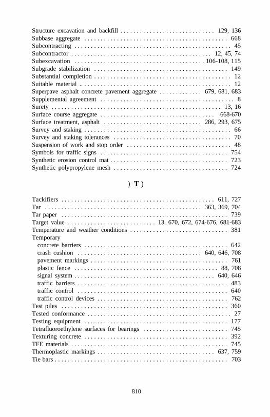
810
Structure excavation and backfill . . . . . . . . . . . . . . . . . . . . . . . . . . . . . 129, 136Subbase aggregate . . . . . . . . . . . . . . . . . . . . . . . . . . . . . . . . . . . . . . . . . . . . 668Subcontracting . . . . . . . . . . . . . . . . . . . . . . . . . . . . . . . . . . . . . . . . . . . . . . . . 45Subcontractor . . . . . . . . . . . . . . . . . . . . . . . . . . . . . . . . . . . . . . . . . . . 12, 45, 74Subexcavation . . . . . . . . . . . . . . . . . . . . . . . . . . . . . . . . . . . . . . . . 106-108, 115Subgrade stabilization . . . . . . . . . . . . . . . . . . . . . . . . . . . . . . . . . . . . . . . . . 149Substantial completion . . . . . . . . . . . . . . . . . . . . . . . . . . . . . . . . . . . . . . . . . . 12Suitable material .. . . . . . . . . . . . . . . . . . . . . . . . . . . . . . . . . . . . . . . . . . . . . . 12Superpave asphalt concrete pavement aggregate . . . . . . . . . . . . . 679, 681, 683Supplemental agreement . . . . . . . . . . . . . . . . . . . . . . . . . . . . . . . . . . . . . . . . . 8Surety . . . . . . . . . . . . . . . . . . . . . . . . . . . . . . . . . . . . . . . . . . . . . . . . . . . . 13, 16Surface course aggregate . . . . . . . . . . . . . . . . . . . . . . . . . . . . . . . . . . . 668-670Surface treatment, asphalt . . . . . . . . . . . . . . . . . . . . . . . . . . . . . . 286, 293, 675Survey and staking . . . . . . . . . . . . . . . . . . . . . . . . . . . . . . . . . . . . . . . . . . . . . 66Survey and staking tolerances . . . . . . . . . . . . . . . . . . . . . . . . . . . . . . . . . . . . 70Suspension of work and stop order . . . . . . . . . . . . . . . . . . . . . . . . . . . . . . . . 48Symbols for traffic signs . . . . . . . . . . . . . . . . . . . . . . . . . . . . . . . . . . . . . . . 754Synthetic erosion control mat . . . . . . . . . . . . . . . . . . . . . . . . . . . . . . . . . . . . 723Synthetic polypropylene mesh . . . . . . . . . . . . . . . . . . . . . . . . . . . . . . . . . . . 724
) T )
Tackifiers . . . . . . . . . . . . . . . . . . . . . . . . . . . . . . . . . . . . . . . . . . . . . . . 611, 727Tar . . . . . . . . . . . . . . . . . . . . . . . . . . . . . . . . . . . . . . . . . . . . . . . . 363, 369, 704Tar paper . . . . . . . . . . . . . . . . . . . . . . . . . . . . . . . . . . . . . . . . . . . . . . . . . . . 739Target value . . . . . . . . . . . . . . . . . . . . . . . . . . . 13, 670, 672, 674-676, 681-683Temperature and weather conditions . . . . . . . . . . . . . . . . . . . . . . . . . . . . . . 381Temporary
concrete barriers . . . . . . . . . . . . . . . . . . . . . . . . . . . . . . . . . . . . . . . . . . . . 642crash cushion . . . . . . . . . . . . . . . . . . . . . . . . . . . . . . . . . . . . . . 640, 646, 708pavement markings . . . . . . . . . . . . . . . . . . . . . . . . . . . . . . . . . . . . . . . . . . 761plastic fence . . . . . . . . . . . . . . . . . . . . . . . . . . . . . . . . . . . . . . . . . . . . 88, 708signal system . . . . . . . . . . . . . . . . . . . . . . . . . . . . . . . . . . . . . . . . . . . 640, 646traffic barriers . . . . . . . . . . . . . . . . . . . . . . . . . . . . . . . . . . . . . . . . . . . . . . 483traffic control . . . . . . . . . . . . . . . . . . . . . . . . . . . . . . . . . . . . . . . . . . . . . . 640traffic control devices . . . . . . . . . . . . . . . . . . . . . . . . . . . . . . . . . . . . . . . . 762
Test piles . . . . . . . . . . . . . . . . . . . . . . . . . . . . . . . . . . . . . . . . . . . . . . . . . . . 360Tested conformance . . . . . . . . . . . . . . . . . . . . . . . . . . . . . . . . . . . . . . . . . . . . 27Testing equipment . . . . . . . . . . . . . . . . . . . . . . . . . . . . . . . . . . . . . . . . . . . . 177Tetrafluoroethylene surfaces for bearings . . . . . . . . . . . . . . . . . . . . . . . . . . 745Texturing concrete . . . . . . . . . . . . . . . . . . . . . . . . . . . . . . . . . . . . . . . . . . . . 392TFE materials . . . . . . . . . . . . . . . . . . . . . . . . . . . . . . . . . . . . . . . . . . . . . . . . 745Thermoplastic markings . . . . . . . . . . . . . . . . . . . . . . . . . . . . . . . . . . . . 637, 759Tie bars . . . . . . . . . . . . . . . . . . . . . . . . . . . . . . . . . . . . . . . . . . . . . . . . . . . . . 703
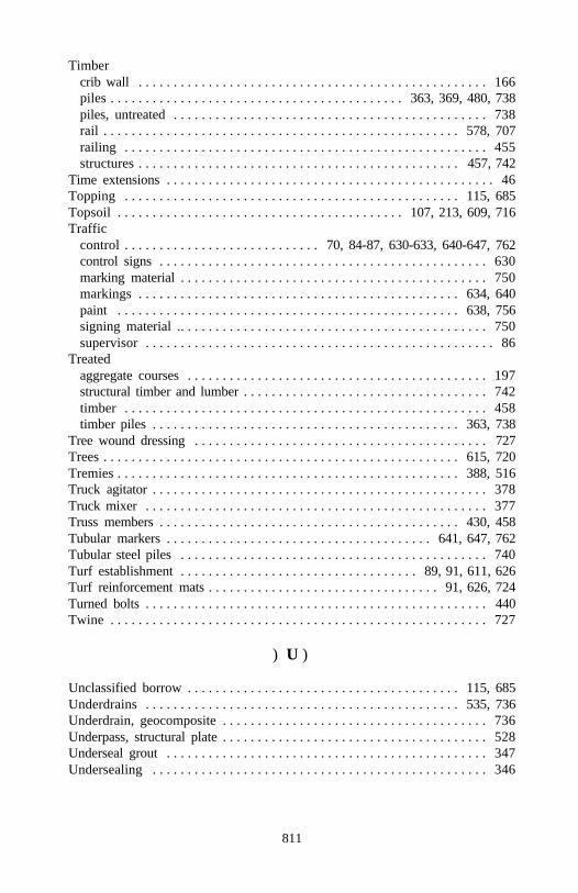
811
Timbercrib wall . . . . . . . . . . . . . . . . . . . . . . . . . . . . . . . . . . . . . . . . . . . . . . . . . . 166piles . . . . . . . . . . . . . . . . . . . . . . . . . . . . . . . . . . . . . . . . . . 363, 369, 480, 738piles, untreated . . . . . . . . . . . . . . . . . . . . . . . . . . . . . . . . . . . . . . . . . . . . . 738rail . . . . . . . . . . . . . . . . . . . . . . . . . . . . . . . . . . . . . . . . . . . . . . . . . . . 578, 707railing . . . . . . . . . . . . . . . . . . . . . . . . . . . . . . . . . . . . . . . . . . . . . . . . . . . . 455structures . . . . . . . . . . . . . . . . . . . . . . . . . . . . . . . . . . . . . . . . . . . . . . 457, 742
Time extensions . . . . . . . . . . . . . . . . . . . . . . . . . . . . . . . . . . . . . . . . . . . . . . . 46Topping . . . . . . . . . . . . . . . . . . . . . . . . . . . . . . . . . . . . . . . . . . . . . . . . 115, 685Topsoil . . . . . . . . . . . . . . . . . . . . . . . . . . . . . . . . . . . . . . . . . 107, 213, 609, 716Traffic
control . . . . . . . . . . . . . . . . . . . . . . . . . . . . 70, 84-87, 630-633, 640-647, 762control signs . . . . . . . . . . . . . . . . . . . . . . . . . . . . . . . . . . . . . . . . . . . . . . . 630marking material . . . . . . . . . . . . . . . . . . . . . . . . . . . . . . . . . . . . . . . . . . . . 750markings . . . . . . . . . . . . . . . . . . . . . . . . . . . . . . . . . . . . . . . . . . . . . . 634, 640paint . . . . . . . . . . . . . . . . . . . . . . . . . . . . . . . . . . . . . . . . . . . . . . . . . 638, 756signing material .. . . . . . . . . . . . . . . . . . . . . . . . . . . . . . . . . . . . . . . . . . . . 750supervisor . . . . . . . . . . . . . . . . . . . . . . . . . . . . . . . . . . . . . . . . . . . . . . . . . . 86
Treatedaggregate courses . . . . . . . . . . . . . . . . . . . . . . . . . . . . . . . . . . . . . . . . . . . 197structural timber and lumber . . . . . . . . . . . . . . . . . . . . . . . . . . . . . . . . . . . 742timber . . . . . . . . . . . . . . . . . . . . . . . . . . . . . . . . . . . . . . . . . . . . . . . . . . . . 458timber piles . . . . . . . . . . . . . . . . . . . . . . . . . . . . . . . . . . . . . . . . . . . . 363, 738
Tree wound dressing . . . . . . . . . . . . . . . . . . . . . . . . . . . . . . . . . . . . . . . . . . 727Trees . . . . . . . . . . . . . . . . . . . . . . . . . . . . . . . . . . . . . . . . . . . . . . . . . . . 615, 720Tremies . . . . . . . . . . . . . . . . . . . . . . . . . . . . . . . . . . . . . . . . . . . . . . . . . 388, 516Truck agitator . . . . . . . . . . . . . . . . . . . . . . . . . . . . . . . . . . . . . . . . . . . . . . . . 378Truck mixer . . . . . . . . . . . . . . . . . . . . . . . . . . . . . . . . . . . . . . . . . . . . . . . . . 377Truss members . . . . . . . . . . . . . . . . . . . . . . . . . . . . . . . . . . . . . . . . . . . 430, 458Tubular markers . . . . . . . . . . . . . . . . . . . . . . . . . . . . . . . . . . . . . . 641, 647, 762Tubular steel piles . . . . . . . . . . . . . . . . . . . . . . . . . . . . . . . . . . . . . . . . . . . . 740Turf establishment . . . . . . . . . . . . . . . . . . . . . . . . . . . . . . . . . . 89, 91, 611, 626Turf reinforcement mats . . . . . . . . . . . . . . . . . . . . . . . . . . . . . . . . . 91, 626, 724Turned bolts . . . . . . . . . . . . . . . . . . . . . . . . . . . . . . . . . . . . . . . . . . . . . . . . . 440Twine . . . . . . . . . . . . . . . . . . . . . . . . . . . . . . . . . . . . . . . . . . . . . . . . . . . . . . 727
) U )
Unclassified borrow . . . . . . . . . . . . . . . . . . . . . . . . . . . . . . . . . . . . . . . 115, 685Underdrains . . . . . . . . . . . . . . . . . . . . . . . . . . . . . . . . . . . . . . . . . . . . . 535, 736Underdrain, geocomposite . . . . . . . . . . . . . . . . . . . . . . . . . . . . . . . . . . . . . . 736Underpass, structural plate . . . . . . . . . . . . . . . . . . . . . . . . . . . . . . . . . . . . . . 528Underseal grout . . . . . . . . . . . . . . . . . . . . . . . . . . . . . . . . . . . . . . . . . . . . . . 347Undersealing . . . . . . . . . . . . . . . . . . . . . . . . . . . . . . . . . . . . . . . . . . . . . . . . 346
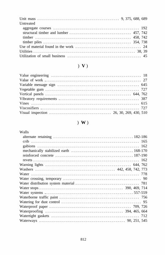
812
Unit mass . . . . . . . . . . . . . . . . . . . . . . . . . . . . . . . . . . . . . . . . . 9, 375, 688, 689Untreated
aggregate courses . . . . . . . . . . . . . . . . . . . . . . . . . . . . . . . . . . . . . . . . . . . 192structural timber and lumber . . . . . . . . . . . . . . . . . . . . . . . . . . . . . . . 457, 742timber . . . . . . . . . . . . . . . . . . . . . . . . . . . . . . . . . . . . . . . . . . . . . . . . 458, 742timber piles . . . . . . . . . . . . . . . . . . . . . . . . . . . . . . . . . . . . . . . . . . . . 354, 738
Use of material found in the work . . . . . . . . . . . . . . . . . . . . . . . . . . . . . . . . . 24Utilities . . . . . . . . . . . . . . . . . . . . . . . . . . . . . . . . . . . . . . . . . . . . . . . . . . . 38, 39Utilization of small business . . . . . . . . . . . . . . . . . . . . . . . . . . . . . . . . . . . . . 45
) V )
Value engineering . . . . . . . . . . . . . . . . . . . . . . . . . . . . . . . . . . . . . . . . . . . . . 18Value of work .. . . . . . . . . . . . . . . . . . . . . . . . . . . . . . . . . . . . . . . . . . . . . . . . 27Variable message sign . . . . . . . . . . . . . . . . . . . . . . . . . . . . . . . . . . . . . . . . . 645Vegetable gum . . . . . . . . . . . . . . . . . . . . . . . . . . . . . . . . . . . . . . . . . . . . . . . 727Vertical panels . . . . . . . . . . . . . . . . . . . . . . . . . . . . . . . . . . . . . . . . . . . 644, 762Vibratory requirements .. . . . . . . . . . . . . . . . . . . . . . . . . . . . . . . . . . . . . . . . 387Vines . . . . . . . . . . . . . . . . . . . . . . . . . . . . . . . . . . . . . . . . . . . . . . . . . . . . . . 615Viscosifiers .. . . . . . . . . . . . . . . . . . . . . . . . . . . . . . . . . . . . . . . . . . . . . . . . . 727Visual inspection . . . . . . . . . . . . . . . . . . . . . . . . . . . . . . . 26, 30, 269, 430, 510
) W )
Wallsalternate retaining . . . . . . . . . . . . . . . . . . . . . . . . . . . . . . . . . . . . . . . . 182-186crib . . . . . . . . . . . . . . . . . . . . . . . . . . . . . . . . . . . . . . . . . . . . . . . . . . . . . . 165gabions . . . . . . . . . . . . . . . . . . . . . . . . . . . . . . . . . . . . . . . . . . . . . . . . . . . 162mechanically stabilized earth . . . . . . . . . . . . . . . . . . . . . . . . . . . . . . . 168-170reinforced concrete . . . . . . . . . . . . . . . . . . . . . . . . . . . . . . . . . . . . . . . 187-190revets . . . . . . . . . . . . . . . . . . . . . . . . . . . . . . . . . . . . . . . . . . . . . . . . . . . . . 162
Warning lights . . . . . . . . . . . . . . . . . . . . . . . . . . . . . . . . . . . . . . . . . . . 644, 762Washers . . . . . . . . . . . . . . . . . . . . . . . . . . . . . . . . . . . . . . . . 442, 458, 742, 773Water . . . . . . . . . . . . . . . . . . . . . . . . . . . . . . . . . . . . . . . . . . . . . . . . . . . . . . 778Water crossing, temporary . . . . . . . . . . . . . . . . . . . . . . . . . . . . . . . . . . . . . . . 90Water distribution system material . . . . . . . . . . . . . . . . . . . . . . . . . . . . . . . . 781Water stops . . . . . . . . . . . . . . . . . . . . . . . . . . . . . . . . . . . . . . . . . . 390, 469, 714Water systems .. . . . . . . . . . . . . . . . . . . . . . . . . . . . . . . . . . . . . . . . . . . . 557-559Waterborne traffic paint . . . . . . . . . . . . . . . . . . . . . . . . . . . . . . . . . . . . . . . . 756Watering for dust control . . . . . . . . . . . . . . . . . . . . . . . . . . . . . . . . . . . . . . . . 95Waterproof paper . . . . . . . . . . . . . . . . . . . . . . . . . . . . . . . . . . . . . . . . . 709, 726Waterproofing . . . . . . . . . . . . . . . . . . . . . . . . . . . . . . . . . . . . . . . 394, 465, 664Watertight gaskets . . . . . . . . . . . . . . . . . . . . . . . . . . . . . . . . . . . . . . . . . . . . 712Waterways . . . . . . . . . . . . . . . . . . . . . . . . . . . . . . . . . . . . . . . . . . . 90, 251, 545
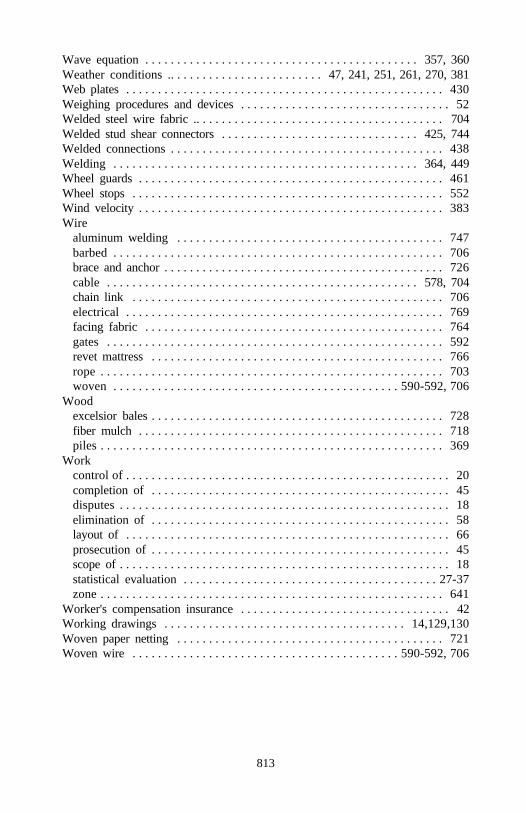
813
Wave equation . . . . . . . . . . . . . . . . . . . . . . . . . . . . . . . . . . . . . . . . . . . 357, 360Weather conditions .. . . . . . . . . . . . . . . . . . . . . . . . 47, 241, 251, 261, 270, 381Web plates . . . . . . . . . . . . . . . . . . . . . . . . . . . . . . . . . . . . . . . . . . . . . . . . . . 430Weighing procedures and devices . . . . . . . . . . . . . . . . . . . . . . . . . . . . . . . . . 52Welded steel wire fabric .. . . . . . . . . . . . . . . . . . . . . . . . . . . . . . . . . . . . . . . 704Welded stud shear connectors . . . . . . . . . . . . . . . . . . . . . . . . . . . . . . . 425, 744Welded connections . . . . . . . . . . . . . . . . . . . . . . . . . . . . . . . . . . . . . . . . . . . 438Welding . . . . . . . . . . . . . . . . . . . . . . . . . . . . . . . . . . . . . . . . . . . . . . . . 364, 449Wheel guards . . . . . . . . . . . . . . . . . . . . . . . . . . . . . . . . . . . . . . . . . . . . . . . . 461Wheel stops . . . . . . . . . . . . . . . . . . . . . . . . . . . . . . . . . . . . . . . . . . . . . . . . . 552Wind velocity . . . . . . . . . . . . . . . . . . . . . . . . . . . . . . . . . . . . . . . . . . . . . . . . 383Wire
aluminum welding . . . . . . . . . . . . . . . . . . . . . . . . . . . . . . . . . . . . . . . . . . 747barbed . . . . . . . . . . . . . . . . . . . . . . . . . . . . . . . . . . . . . . . . . . . . . . . . . . . . 706brace and anchor . . . . . . . . . . . . . . . . . . . . . . . . . . . . . . . . . . . . . . . . . . . . 726cable . . . . . . . . . . . . . . . . . . . . . . . . . . . . . . . . . . . . . . . . . . . . . . . . . 578, 704chain link . . . . . . . . . . . . . . . . . . . . . . . . . . . . . . . . . . . . . . . . . . . . . . . . . 706electrical . . . . . . . . . . . . . . . . . . . . . . . . . . . . . . . . . . . . . . . . . . . . . . . . . . 769facing fabric . . . . . . . . . . . . . . . . . . . . . . . . . . . . . . . . . . . . . . . . . . . . . . . 764gates . . . . . . . . . . . . . . . . . . . . . . . . . . . . . . . . . . . . . . . . . . . . . . . . . . . . . 592revet mattress . . . . . . . . . . . . . . . . . . . . . . . . . . . . . . . . . . . . . . . . . . . . . . 766rope . . . . . . . . . . . . . . . . . . . . . . . . . . . . . . . . . . . . . . . . . . . . . . . . . . . . . . 703woven . . . . . . . . . . . . . . . . . . . . . . . . . . . . . . . . . . . . . . . . . . . . . 590-592, 706
Woodexcelsior bales . . . . . . . . . . . . . . . . . . . . . . . . . . . . . . . . . . . . . . . . . . . . . . 728fiber mulch . . . . . . . . . . . . . . . . . . . . . . . . . . . . . . . . . . . . . . . . . . . . . . . . 718piles . . . . . . . . . . . . . . . . . . . . . . . . . . . . . . . . . . . . . . . . . . . . . . . . . . . . . . 369
Workcontrol of . . . . . . . . . . . . . . . . . . . . . . . . . . . . . . . . . . . . . . . . . . . . . . . . . . . 20completion of . . . . . . . . . . . . . . . . . . . . . . . . . . . . . . . . . . . . . . . . . . . . . . . 45disputes . . . . . . . . . . . . . . . . . . . . . . . . . . . . . . . . . . . . . . . . . . . . . . . . . . . . 18elimination of . . . . . . . . . . . . . . . . . . . . . . . . . . . . . . . . . . . . . . . . . . . . . . . 58layout of . . . . . . . . . . . . . . . . . . . . . . . . . . . . . . . . . . . . . . . . . . . . . . . . . . . 66prosecution of . . . . . . . . . . . . . . . . . . . . . . . . . . . . . . . . . . . . . . . . . . . . . . . 45scope of . . . . . . . . . . . . . . . . . . . . . . . . . . . . . . . . . . . . . . . . . . . . . . . . . . . . 18statistical evaluation . . . . . . . . . . . . . . . . . . . . . . . . . . . . . . . . . . . . . . . . 27-37zone . . . . . . . . . . . . . . . . . . . . . . . . . . . . . . . . . . . . . . . . . . . . . . . . . . . . . . 641
Worker's compensation insurance . . . . . . . . . . . . . . . . . . . . . . . . . . . . . . . . . 42Working drawings . . . . . . . . . . . . . . . . . . . . . . . . . . . . . . . . . . . . . . 14,129,130Woven paper netting . . . . . . . . . . . . . . . . . . . . . . . . . . . . . . . . . . . . . . . . . . 721Woven wire . . . . . . . . . . . . . . . . . . . . . . . . . . . . . . . . . . . . . . . . . . 590-592, 706


![U.S. DEPARTMENT OF TRANSPORTATION FEDERAL …1].pdf · U.S. DEPARTMENT OF TRANSPORTATION FEDERAL AVIATION ADMINISTRATION ... and Equipment Profile (FSEP): DRPDS, Potomac TRACON (PCT),](https://img.pdfslide.us/doc/110x75/5a723c707f8b9a93538d890d/us-department-of-transportation-federal-1pdfpdf-fileus.jpg)