Embed Size (px)
Citation preview
James D. Seipel Acting Manager, Design, Manufacturing, &
Airworthiness Division Aircraft Certification Service
Advisory U.S. Department of Transportation Circular Federal Aviation Administration
Subject: Service Bulletins Related to Date: 06/16/2014 AC No: 20-176A Airworthiness Directives and Indicating FAA Initiated by: AIR-140 Approval on Service Documents
This advisory circular (AC) presents best practices for drafting service bulletins (SB) related to an airworthiness directive (AD). This AC also provides information and guidance on ex parté communication and alternative methods of compliance (AMOC), as well as means for avoiding overlapping and conflicting actions in SBs and maintaining airworthiness of AD-mandated design changes. This revision, AC 20-176A, includes guidance for indicating FAA approval on a service document.
If you have any suggestions for improvements or changes, you may use the template provided at the end of this AC.
06/16/2014 AC 20-176A
Table of Contents
Chapter 1. General Information................................................................................................. 1
1-1. Purpose ..................................................................................................................... 1 1-2. Applicability............................................................................................................. 1 1-3. Cancellation.............................................................................................................. 1 1-4. Explanation of Changes............................................................................................ 2 1-5. Background .............................................................................................................. 2 1-6. Scope ........................................................................................................................ 3 1-7. Definitions ................................................................................................................ 3 1-8. Discussion ................................................................................................................ 4
Chapter 2. User-Friendly Service Bulletins............................................................................... 5
2-1. General ..................................................................................................................... 5 2-2. SB Improvements ..................................................................................................... 5 2-3. Standardized Format and Content ............................................................................ 5 2-4. Safety Intent and Configuration Description............................................................ 7 2-5. Ambiguous Language............................................................................................... 8 2-6. Notes......................................................................................................................... 9 2-7. Figures, Illustrations, and Drawings....................................................................... 10 2-8. Logic-based Diagrams............................................................................................ 10 2-9. Mandatory versus Flexible Language .................................................................... 10 2-10. Critical Task Differentiation .................................................................................. 12 2-11. Streamlining Development and Revision of SBs ................................................... 16 2-12. Ex Parté .................................................................................................................. 17
Chapter 3. Avoiding Overlapping and Conflicting Actions in SBs....................................... 18
3-1. General ................................................................................................................... 18 3-2. Tracking and Management Process........................................................................ 18
Chapter 4. AMOCs .................................................................................................................... 19
4-1. General ................................................................................................................... 19 4-2. Sharing AMOCs with DAHs.................................................................................. 19 4-3. DAH Determination for Global AMOCs ............................................................... 19 4-4. Posting Global AMOCs on Website ...................................................................... 20 4-5. Minimizing AMOC Requests for Part Changes..................................................... 20 4-6. 24/7 AMOC Support .............................................................................................. 20
Chapter 5. Maintaining Airworthiness of AD-Mandated Design Changes.......................... 22
5-1. General ................................................................................................................... 22 5-2. Maintenance of an AD-Mandated Design Change................................................. 22 5-3. Availability of Maintenance Procedures or ICA.................................................... 22 5-4. Allowing Flexibility ............................................................................................... 23
i
06/16/2014 AC 20-176A
Table of Contents (Continued)
5-5. Flagging Procedures ............................................................................................... 23 5-6. SB-to-AD Cross Referencing................................................................................. 23
Chapter 6. FAA Approval of Service Documents ................................................................... 24
6-1. General ................................................................................................................... 24 6-2. FAA-Approval of a Service Document.................................................................. 24 6-4. Indicating FAA-Approval ...................................................................................... 24 6-5. Revisions to Service Documents............................................................................ 25
Appendix A. Examples of Notes in SBs (1 page) .................................................................. A-1
Appendix B. Examples of Notes that Provide Flexibility in SBs (2 pages) ........................ B-1
Appendix C. Examples of Concepts to Clarify Illustrations (4 pages) .............................. C-1
Appendix D. Example of Logic-Based Diagrams (1 page) .................................................. D-1
Appendix E. Related FAA Publications (1 page) ................................................................. E-1
Appendix F. Acronyms (1 page) ..............................................................................................F-1
Appendix G. Advisory Circular Feedback Information (1 page) .......................................G-1
ii
06/16/2014 AC 20-176A
Chapter 1. General Information
1-1. Purpose.
a. This advisory circular (AC) provides:
(1) Best practices and recommendations for design approval holder (DAH) for developing service bulletin (SB) descriptive data to resolve an unsafe condition, including guidance for:
(a) Avoiding overlapping and conflicting information in SBs, and
(b) Maintaining compliance with an airworthiness directive (AD)-mandated design change.
(2) Guidance for owners and operators to share alternative methods of compliance (AMOC) with DAHs, as well as recommendations for DAHs to:
(a) Review Federal Aviation Administration (FAA)-approved AMOCs to determine whether they are candidates for global AMOCs;
(b) Consider a process for posting global AMOCs on the DAH website;
(c) Help minimize the number of AMOC requests to an AD requiring part changes; and
(d) Develop a process for 24/7 AMOC support.
(3) References for industry-wide guidance on ex parté communication in AD activities.
(4) An acceptable means, but not the only means, for indicating FAA approval of engineering data in a service document.
b. The guidance in Chapters 2 through 5 is derived from FAA and industry experience on SBs related to ADs and AMOCs. While it is not mandatory, implementation of any, or all, aspects of this AC will enhance the AD process, facilitate continued compliance with an AD, minimize the need for AMOCs, and reduce the potential for fleet-wide AD compliance issues that could disrupt air transportation. This AC describes an acceptable means, but not the only means, for drafting SBs related to ADs.
1-2. Applicability. This AC is for manufacturers who draft service documents, including DAHs of aircraft, aircraft engines, propellers, and appliances who draft SBs that are, or will be, associated with an AD. The AC is also for owners and operators who must comply with an AD, or request approval of an AMOC.
1-3. Cancellation. This AC cancels:
1
06/16/2014 AC 20-176A
a. AC 20-176, Design Approval Holder Best Practices for Service Bulletins Related to Airworthiness Directives, dated December 19, 2011.
b. AC 20-114, Manufacturers’ Service Documents, dated October 22, 1981.
1-4. Explanation of Changes. This revision includes the following changes:
a. Provides a definition for FAA designee and service documents as used in this document (see paragraphs 1-8c and 6-2a).
b. Clarifies guidance for referring to other documents in an SB (see paragraphs 2-3b(2) and 2-3c).
c. Clarifies when to use the required for compliance (RC) label (see paragraph 2-10e(3)).
d. Adds new guidance related to revising or changing an SB with the RC label (see paragraph 2-10f).
e. Clarifies ex parté guidance (see paragraphs 2-12a and 2-12b).
f. Revises guidance for later-approved parts to align with FAA Order 8110.117, Service Bulletins Related to Airworthiness Directives (see paragraphs 4-5c, 4-5d, and 4-5e).
g. Adds guidance regarding the information a DAH must submit to the FAA or organization designation authorization (ODA) to use later-approved parts without an AMOC (see paragraph 4-5d).
h. Adds a new chapter 6 to include guidance previously addressed in AC 20-114 for approval of service documents.
1-5. Background.
a. In early March and April 2008, events of suspected noncompliance with ADs prompted the FAA to establish an AD Compliance Review Team (AD CRT) consisting of FAA and industry subject matter experts. The team reviewed compliance issues related to AD 2006-1515, McDonnell Douglas Model DC-9-81 (MD-81), DC-9-82 (MD-82), DC-9-83 (MD-83), DC9-87 (MD-87), and MD-88 Airplanes (Task 1), and the general process for developing and implementing ADs for commercial airplanes (Task 2).
b. The AD CRT documented its findings and recommendations from the Task 2 review in a report1 that focused on the process of developing and implementing ADs, as well as ensuring compliance by owners and operators. The recommendations do not fundamentally change the AD process, but provide suggested enhancements and improvements. The response to some of those recommendations is addressed in this AC (i.e., Recommendation Nos. 1 and 9, and parts of Recommendation Nos. 3 and 4).
1 Process Review Technical Report – A review of the Title 14, Code of Federal Regulations, part 39 airworthiness directives process for commercial airplanes, dated July 8, 2009.
2
06/16/2014 AC 20-176A
c. The AD CRT’s report acknowledged that the AD-friendly SB initiative,2 developed in 2001 between the FAA and a commercial transport airplane DAH, has improved the format and quality of SBs specified in ADs as the appropriate source of compliance information. By applying agreed-upon principles for writing SBs (e.g., standardized format/location of information, use of acceptable terminology, etc.), SBs can be referenced as the primary source of information for product applicability, compliance times, and key actions in an AD in lieu of rewriting the SB information in the AD itself.
1-6. Scope. This AC, except Chapter 6, addresses only SBs that are, or will be, referenced in an AD as an additional source of information about the unsafe condition, or as a document that will be incorporated by reference (IBR’d) in an AD. Development of SBs for other purposes is outside the scope of this AC. Chapter 6 applies to all service documents, including those not related to an AD.
1-7. Definitions. For the purposes of this AC, the following definitions are used:
a. AD Action. One of the following types of rulemaking documents issued under Title 14 of the Code of Federal Regulations (14 CFR) part 39 by the FAA, including supersedures, revisions, and corrections to those documents:
(1) Notice of Proposed Rulemaking (NPRM), including a supplemental NPRM (SNPRM);
(2) Final rule after NPRM or SNPRM;
(3) Final rule, request for comments (i.e., Immediately Adopted Rule (IAR), No-Notice Final Rule (NFR), or Federal Register Version of an Emergency AD (FRV)); or
(4) Emergency AD.
b. Drawing. A document created to define a configuration. Drawings may include other engineering information such as specifications, dimensions, materials, and processes.
c. FAA Designee. A designated engineering representative (DER) or a unit member (UM) for an ODA holder who has been delegated authority to approve or recommend approval of engineering technical data on behalf of the FAA.
d. Figure. An illustration, photograph, chart, graph, table, form, note, symbol, callout, text, or dimension (or any combination thereof) that supports or clarifies the written instructions.
e. Global AMOC. An AMOC of general applicability that applies to two or more owners or operators.
2 “Agreed Principles and Practices on AD Friendly Service Bulletins Between the Seattle Aircraft Certification Office (SACO), Los Angeles Aircraft Certification Office (LAACO) and Boeing Commercial Airplanes,” dated March 31, 2006.
3
06/16/2014 AC 20-176A
f. Illustration. A pictorial graphic.
g. IBR. A method of referring to material already published elsewhere instead of publishing it directly into an AD. Documents IBR’d in an AD become part of the AD. The FAA must obtain approval from the Office of the Federal Register (OFR) to IBR material, including an SB or portion of an SB, in an AD.
h. Product. An aircraft, aircraft engine, propeller, and appliance.
i. RC. A method of notating which steps in an SB must be completed for compliance with an AD. Steps with the RC notation have a direct effect on detecting, preventing, resolving, or eliminating the unsafe condition identified in an AD.
j. SB. Document used to convey service information to owners and operators of products (e.g., modifications, inspections, etc.).
1-8. Discussion.
a. The FAA issues an AD when an unsafe condition is found to exist in a product and the condition is likely to exist or develop in other products of the same type design.
(1) The action(s) specified in an AD are intended to detect, prevent, resolve, or eliminate the unsafe condition. Those actions can either be written directly into the regulatory portion (“body”) of the AD, or another document such as an SB can be IBR’d. Compliance with an SB, or a portion of an SB, that is IBR’d in an AD is mandatory.
(2) An AD might also refer to an SB as an additional source of information about the subject of the AD. These SBs are not submitted for IBR approval; therefore, reference to these SBs does not constitute a regulatory requirement and accomplishing the action(s) in the SB is not required for compliance with the AD.
b. It is the owners/operator’s ultimate responsibility to ensure that FAA approval was obtained if FAA approval is required before using the advice, recommendations, alterations, repairs, etc., prescribed in service documents. For this reason, it is desirable for the DAH to assist the owner and operator by indicating in the body of service documents specifically what information was approved by the FAA or its designees.
4
06/16/2014 AC 20-176A
Chapter 2. User-Friendly Service Bulletins
2-1. General. This chapter provides best practices and recommendations on how DAHs can improve the quality and usability of SBs associated with an AD action. It also provides guidance for streamlining the SB development and revision processes for such SBs, and provides references for where to find information on ex parté communication.
2-2. SB Improvements.
a. An SB that may be referenced in an AD as an additional source of information about the unsafe condition or IBR’d in an AD, should be written so owners and operators can understand and follow the accomplishment instructions. The following SB improvements will be discussed further in this chapter:
(1) Providing a standardized format and structure so the reader can easily locate important information on effectivity, compliance times, and accomplishment instructions (see paragraph 2-3).
(2) Including a clear and concise description of the safety intent of the SB as well as a precise description of the new configuration that removes the unsafe condition (see paragraph 2-4).
(3) Writing clear, concise, and unambiguous technical instructions that minimize the possibility of omission, error, or extensive judgment (see paragraphs 2-5 and 2-6).
(4) Giving clear, detailed illustrations appropriate to the task, and that help the user understand how to sequence and accomplish the tasks and/or steps (see paragraphs 2-7 and 2-8).
(5) Allowing use of industry standards or practices acceptable to the FAA (see paragraph 2-9).
(6) Differentiating critical tasks and task sequences requiring exact conformance from tasks that can be flexible, advisory, or common acceptable procedures (see paragraph 2-10).
(7) Streamlining the SB development and revision processes (see paragraph 2-11).
b. The concepts presented in this AC apply to development of new or revised SBs and are not intended to be applied retroactively, except when deemed necessary by the DAH and FAA (see paragraph 2-4b).
2-3. Standardized Format and Content.
a. The format and content of an SB should follow industry specifications for technical documents. Refer to the following documents:
(1) Air Transportation Association (ATA) Spec 2200, Information Standards for Aviation Maintenance.
5
06/16/2014 AC 20-176A
(2) S1000D, International Specification for Technical Publications.
b. The accomplishment instructions in an SB should address resolving the unsafe condition identified in the AD. Sometimes, however, procedures are already published in other DAH documents which accomplish this goal. As such, the following guidelines are provided to help determine what procedures should, or should not, be included in an SB:
(1) When appropriate, include the following types of procedures in the SB:
(a) Inspection or test procedures that do not exist in a published DAH document available to other parties.
(b) Critical requirements in procedures that exist in manuals that are not FAA-approved (e.g., torque values, gap measurements, electrical bonding, etc.). List in the SB the critical requirements that must be met to comply with a planned AD and refer to the procedure in the manual that is not FAA-approved as an accepted procedure to achieve those requirements (see paragraph 2-9).
(c) Revised procedures when the original procedure(s) are in error.
(2) Do not duplicate (e.g., copy) the following types of procedures in an SB if affected owners and operators have the procedures in other documents (see paragraph 2-3c below). Instead of repeating the procedure, refer to the other document(s) for that task. For example:
(a) Procedures that exist in other documents accessible by other parties (e.g., DAH SBs/manuals, component SBs, and supplier SBs).
(b) Common industry practices, including, but not limited to, the Standard Overhaul Practices Manual (SOPM) and Standard Wiring Practices Manual (SWPM).
(c) Tests for all components or systems that may be disturbed during incorporation of an SB. An SB should specify only the testing necessary to ensure the new or modified system operates as intended after the modification is complete (i.e., unsafe condition is resolved). Any additional functional tests that may be necessary due to an interruption to other airplane systems can be addressed in a note in the SB (see appendix A, paragraph 5).
c. For a requirement to use other documents to be enforceable, the affected operators must have actual notice of them. As such, before relying on references to other documents in SBs that will be IBR’d, confirm that affected operators actually have the referenced document.
d. If an SB uses mandatory language (e.g., “use,” “in accordance with”) to reference another document for completing a task required for compliance with an AD (reference paragraphs 2-9 and 2-10), include the revision level and date of the other document(s) within the SB. To prevent the need for an AMOC approval each time the revision level changes in the document referenced in the SB, the phrase "or later approved revision" may be added when specifying the revision level.
6
06/16/2014 AC 20-176A
e. Use the following guidelines to refer to other document(s) in an SB:
(1) Specify the specific section(s) of the document that are applicable. Do not provide a blanket reference to the other document if only portions of the other document are applicable.
(2) Do not refer to documents that simply refer to other documents. Instead refer to the end document that provides the actual instruction.
(3) Do not refer to documents that do not provide sufficient information to perform the task (e.g., “Cad plate per SOPM AA-XX-YY” if document SOPM AA-XX-YY does not specify the type of cad plating for the specific part).
2-4. Safety Intent and Configuration Description. a. When drafting an SB that might be IBR’d in an AD, the SB should contain a paragraph
entitled “Safety Intent.” For ADs that will change the configuration of a part (e.g., a design change), a “Configuration Description” paragraph is also required. Place the paragraphs next to one another upfront in the SB (e.g., after the “Reason” paragraph). These paragraphs are intended to enhance and focus awareness of the safety issue during the development and approval of the SB as well as during implementation and subsequent maintenance.
(1) The “Safety Intent” paragraph should explain what accomplishment of the SB is intended to do (i.e., prevent, resolve, or otherwise remove the unsafe condition). The description should be a succinct and clear statement of the specific technical objective of the instructions. For example, “The safety intent of this SB is to prevent electrical arcing between a wire bundle and control cables in the main wheel well, which, if not corrected, could cause a hydraulic or electrical fire.” The goal is to explain in technical terms what the affected part and failure mode or malfunction is, and how it will be prevented, resolved, or otherwise removed by accomplishing the SB. This differs from the “Reason” paragraph in most SBs, which typically provide the history and reason for taking the SB action.
(2) If accomplishing the SB will change configuration, a “Configuration Description” paragraph should be included that provides a succinct, high-level description of the design change that will result from accomplishing the instructions. For example, “Incorporating this SB results in installing a new wire bundle (P/N 123456) between the J135 and J234 connectors, and installing several standoffs of increased length to hold the wire bundle clear of contact.” The “Configuration Description” should:
(a) Be limited to the features that will prevent development or recurrence of the unsafe condition, once the configuration has been implemented. The paragraph can provide the greatest value in SBs that specify ‘high risk’ modifications (e.g., instructions that are complex, workmanship intensive, or susceptible to reversal in operations).
(b) Assist in understanding the post-installation mandated configuration. The “Configuration Description” may guide, but cannot be used as the final determinant of compliance with an AD.
7
06/16/2014 AC 20-176A
(c) For an AD that will require installation of a different part, the part number of the new part should differ from that of the original. If changing the part number (i.e., “rolling” the part number) is impractical, identify the “modification level” of the part. The configuration description for this case should control the part by the “modification level” in addition to the part number identification.
(d) Identify a specific part, sub-assembly, or assembly of a component affected by the safety intent. An affected component “part number” may contain both “good” and “bad” parts, sub-assemblies, or assemblies. But because the part number of the component might not have been changed or “rolled” to differentiate the configurations, identification using the component part number alone is inadequate. Therefore, the configuration description for such a case should control the specific parts, sub-assemblies, or assemblies in addition to the part number identification of the affected component.
b. For SBs originally written for reliability or economic enhancements that subsequently are found to provide correction of a safety issue, those SB should be revised to include the “Safety Intent” and “Configuration Description” paragraphs per the guidance in this AC.
2-5. Ambiguous Language.
a. Avoid unclear and confusing terms when writing an SB. See table 1 below for examples of ambiguous language used in SBs and how to rewrite them for clarity.
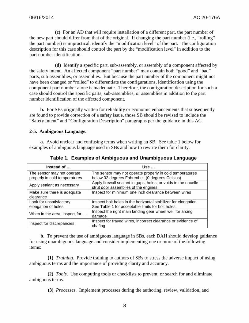
Table 1. Examples of Ambiguous and Unambiguous Language
Instead of … Use … The sensor may not operate properly in cold temperatures
The sensor may not operate properly in cold temperatures below 32 degrees Fahrenheit (0 degrees Celsius)
Apply sealant as necessary Apply firewall sealant in gaps, holes, or voids in the nacelle strut door assemblies of the engines
Make sure there is adequate clearance
Inspect for minimum one inch clearance between wires
Look for unsatisfactory elongation of holes
Inspect bolt holes in the horizontal stabilizer for elongation. See Table 1 for acceptable limits for bolt holes.
When in the area, inspect for … Inspect the right main landing gear wheel well for arcing damage
Inspect for discrepancies Inspect for frayed wires, incorrect clearance or evidence of chafing
b. To prevent the use of ambiguous language in SBs, each DAH should develop guidance for using unambiguous language and consider implementing one or more of the following items:
(1) Training. Provide training to authors of SBs to stress the adverse impact of using ambiguous terms and the importance of providing clarity and accuracy.
(2) Tools. Use computing tools or checklists to prevent, or search for and eliminate ambiguous terms.
(3) Processes. Implement processes during the authoring, review, validation, and
8
06/16/2014 AC 20-176A
DAH internal approval of SBs that will prevent the use of ambiguous terms.
(4) Draft Review. For SBs related to transport airplanes or engines installed thereon, implement a process during validation to allow the draft SB to be reviewed by the lead airline (see paragraph 2-11c(8)) so that ambiguous terms can be eliminated prior to issuance of the SB.
2-6. Notes.
a. Notes in SBs generally provide information related to the accomplishment of instruction steps. However, notes are informational only, and since they are generally unenforceable, they should not contain any requirements. Authors, therefore, are strongly encouraged to review notes to ensure they do not contain any critical step(s) for accomplishing the corrective action(s).
b. Unless specified otherwise, notes apply to figures, illustrations, and drawings within the SB. Refer to appendix A for examples of notes that can be used in SBs.
c. When possible, write notes such that the SB user has an acceptable level of flexibility to accomplish the tasks (e.g., specify alternative materials; allow acceptance to use other approved methods, techniques and practices, etc.). Refer to appendix B for examples.
d. If referring to other documents within an SB, ensure that the notes specified in the referenced document do not conflict with notes in the SB. If there is a conflict, add a note in the SB to specify which note takes precedence.
e. For SBs related to transport airplanes or engines installed thereon, seek lead airline review of the notes (reference paragraph 2-11c(8)) so that those who will be implementing the SB have an opportunity to make suggestions as necessary.
f. Notes should be placed at the beginning of the accomplishment instructions or adjacent to the relevant information (e.g., figure, illustration, etc.), as appropriate, and may include items such as:
(1) Referring to a list or document of acceptable alternative parts, materials, and processes;
(2) Specifying or referring to other documents for standard tolerances and dimensions;
(3) Providing warnings and cautions that apply to the entire set of accomplishment instructions;
(4) Specifying standard practices that apply to the entire set of accomplishment instructions;
(5) Providing definitions for inspections specified in the service information; and
(6) Referring to DAH maintenance documentation.
9
06/16/2014 AC 20-176A
2-7. Figures, Illustrations, and Drawings.
a. To avoid subjective misinterpretation, the text in the accomplishment instructions must be the authoritative information. Use figures, illustrations, and drawings to supplement the accomplishment instructions. If a discrepancy between the accomplishment instructions and a figure, illustration, or drawing exists, the discrepancy must be evaluated and corrected.
b. Dimensions should be added to clearly define locations, such as installation of parts.
c. Tolerances should be included for measured values (e.g., dimensions, torque values, temperature). This can be done in the figure, illustration, or drawing itself, or in general notes in the SB (e.g., “All dimensions given have a tolerance of +/- 5mm unless otherwise stated.”).
d. Phantom lines, shading or cross hatching, and enlarged views should be used to assist in distinguishing important information from “reference only” information. Refer to appendix C for examples.
e. For SBs related to transport airplanes or engines installed thereon, seek lead airline review of the figures (reference paragraph 2-11c(8) of this AC) so that those who will be implementing the SB have an opportunity to make suggestions.
2-8. Logic-based Diagrams. An SB specifying numerous compliance times, configurations, conditions, and alternative corrective actions can be difficult to follow. For such cases, a logic-based diagram (e.g., a flowchart) is a useful tool to assist owners and operators in choosing the best corrective path, such as repetitive inspections or a terminating modification, based upon the discovered condition and compliance times.
a. It is the responsibility of the DAH to determine if logic-based diagram(s) would help simplify a complex SB. Consideration should be given to requests from owners, operators or the FAA as to whether a logic-based diagram would be helpful.
b. A logic-based diagram cannot be the primary source for tasks or compliance times in the SB. If used, logic-based diagrams should:
(1) Be located in an appendix in the SB;
(2) Use descriptive, concise, and consistent terminology; and
(3) Contain a note in both the logic-based diagram and the accomplishment instructions paragraph of the SB so it is clear that the logic-based diagram only supplements the information in the accomplishment instructions.
c. For SBs related to transport airplanes or engines installed thereon, ensure that the lead airline reviews the draft logic-based diagram (see paragraph 2-11c(8)) and agrees that there is no confusion with the intent of the diagram.
2-9. Mandatory versus Flexible Language. The use of mandatory language in the accomplishment instructions of an SB depends on whether other procedures acceptable to the
10
---
06/16/2014 AC 20-176A
FAA are adequate to address the unsafe condition in an AD. If other procedures are acceptable to the FAA, use non-mandatory language in the SB.
a. When a procedure or document must be followed to accomplish a task in an SB, the appropriate terminology to cite the procedure or document is “in accordance with.” Use “in accordance with” for:
(1) A process or procedure that must be followed exactly to resolve the unsafe condition and comply with the AD. Also consider including the steps of the process or procedure in the SB and a note not to change the process or procedure without full consideration of the consequences. An example of a procedure that is frequently cited as one that must be followed is the Non-Destructive Test (NDT) procedure developed to address a specific condition that is self-contained in the SB and not duplicated in the NDT manual.
(2) Documents approved by a regulatory authority that must be used to ensure the part is installed, changed, or tested per the specific instruction. Documents approved by a regulatory authority when specified in DAH SBs may include, but are not limited to:
(a) Structural Repair Manual (SRM);
(b) Other SBs (e.g., Component, Supplier, etc.); or
(c) Airworthiness Limitations Section of the Instructions for Continued Airworthiness (ICA).
b. When a procedure or document may be followed to accomplish an action (e.g., the DAH’s procedure or document may be used, but an FAA-accepted procedure could also be used), the appropriate terminology to use to cite the procedure or document is “refer to ... as an accepted procedure.” Use this flexible language when referring to procedures in documents acceptable to the FAA and when owner or operators may use the document or their own procedure that is acceptable to the FAA. Documents or procedures acceptable to the FAA may include, but are not limited to:
(1) Aircraft Maintenance Manual (AMM) for access, removal, and testing;
(2) SWPM for standard industry wiring procedures such as installing wiring, electrical bonding and grounding, cleaning electrical connectors, etc.;
(3) SOPM for standard industry procedures such as general cleaning procedures, application of adhesives, lubricants, sealants, application of stencils, etc.;
(4) Overhaul Manual (OHM) and Component Maintenance Manual (CMM) for disassembly, assembly, and testing;
(5) Fault Isolation Manual (FIM);
(6) Wiring Diagram Manual (WDM); or
11
06/16/2014 AC 20-176A
(7) Generic or common NDT manual procedures not developed for a specific SB application.
c. When using “in accordance with” or “refer to” language in an SB, the DAH should include a note explaining the meaning of that language. For example:
“Note: These work instructions refer to methods, techniques, and practices described in other {specify DAH name} documents. When the words "refer to" are used and there are other acceptable methods, techniques, and practices (including tools, equipment, and test equipment) those acceptable methods, techniques, practices (including tools, equipment, and test equipment) may be used to complete the work. When the words "in accordance with" are included in the instruction, the methods, techniques, and practices specified (including tools, equipment, and test equipment) in the {specify DAH name} document must be used.”
2-10. Critical Task Differentiation. Steps that have a direct effect on detecting, preventing, resolving, or eliminating the unsafe condition in an AD should be identified in an SB with “RC.” Any substitutions or changes to RC steps will require an AMOC approval. Differentiating these steps from other tasks in an SB will improve an owner’s or operator’s understanding of which steps in the SB must be done to comply with the AD and help provide consistent judgment in AD compliance.
a. When using critical task differentiation, a DAH should coordinate with the FAA early in the SB development process to determine if the SB might be IBR’d in an AD and if the RC steps are appropriately labeled using the guidance in this AC or other methods acceptable to the FAA.
(1) Step(s) labeled as RC apply solely to the SB that is IBR’d in the AD. The designation is not transferable or implied as applicable to any other document.
(2) A DAH must include a note in the SB to define RC. An example is:
“Note: Some steps in the accomplishment instructions are identified as Required for Compliance (RC). If this service bulletin is mandated by an airworthiness directive (AD), the steps identified as RC must be done to comply with the AD. Steps not identified with RC are recommended and may be deviated from; done as a part of other actions; or done with accepted methods different from those given in SB if the RC steps can be done and the airplane returned to a serviceable condition.”
b. Sometimes an SB is issued before a decision is made by the FAA to reference the SB as the appropriate source of information for compliance with an AD. If an SB is published without tasks labeled with RC, the SB can be revised to include the RC label. Depending where
12
--
06/16/2014 AC 20-176A
in the AD process the AD action is, the revised SB can be referenced in the final rule AD as the appropriate source of information for compliance or be FAA approved as a global AMOC to the AD.
c. In general, if any of the following items are included in an SB due to a design deficiency, manufacturing error, systemic maintenance error, or repair, and directly impact the detection, removal, prevention, or resolution of the unsafe condition, the item should be labeled with RC. For example:
(1) Inspection methods, techniques or practices that are necessary to detect the unsafe condition. This includes repetitive inspections or a terminating action such as a repair.
(2) Removal or installation of part(s), including any hardware necessary to support the new part.
(3) Steps required to directly accomplish a change to an aircraft or component to resolve an unsafe condition (e.g., parts, material, dimensions, methods, and processes).
(4) Steps such as application of corrosion inhibiting compound, application of sealant, cleaning of surfaces for proper bonding, replacing lubricant, etc. The step to use the material may be labeled RC or the specific type of material may be labeled RC. However, the SB may refer to standard practices to apply the material.
(5) Repair methods, techniques or practices, including steps that specify to contact the DAH for repair, modification, or testing instructions.
(6) Operational or functional test procedures or test criteria to ensure the repaired or modified system is operating properly. This includes any necessary corrective action if the test failed.
(7) Recording data (such as pressure readings, torque readings, temperature readings, gap measurements, dimensions, etc.) that is specifically required to properly complete the inspection, repair, or modification.
d. In general, if any of the following items are included in an SB and do not directly impact the detection, removal, prevention, or resolution of the unsafe condition, the items should not be identified as RC in an SB:
(1) Aircraft preparation steps (e.g., removing electrical power, opening and tagging circuit breakers, jacking and shoring, etc.).
(2) Access steps (e.g., removing access panels, removing sidewall panels, removing galleys or lavatories, etc.).
(3) Access restoration steps (e.g., installing access panels, sidewall panels, galleys or lavatories, etc.).
13
06/16/2014 AC 20-176A
(4) Airplane restoration steps (e.g., restoring electrical power, closing circuit breakers, removing jacking and shoring, etc.).
(5) Steps such as cleaning, painting, trimming, etc., that do not directly remove, prevent, or resolve the unsafe condition.
(6) Steps to update maintenance records to show that the SB has been accomplished, which is already required by regulation.
(7) Steps to report results, such as inspection findings.
(8) Steps to perform operational test procedures because of interruption to other aircraft systems (e.g., disconnection of a hydraulic system to gain access to an area or a test of the hydraulic system after it is reconnected).
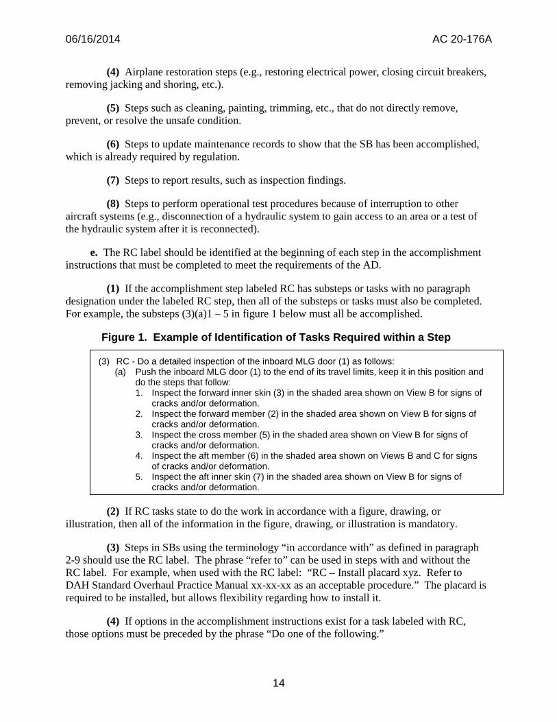
e. The RC label should be identified at the beginning of each step in the accomplishment instructions that must be completed to meet the requirements of the AD.
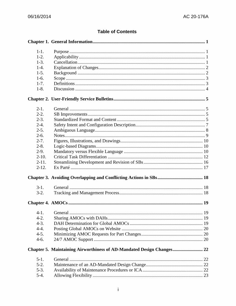
(1) If the accomplishment step labeled RC has substeps or tasks with no paragraph designation under the labeled RC step, then all of the substeps or tasks must also be completed. For example, the substeps (3)(a)1 – 5 in figure 1 below must all be accomplished.
Figure 1. Example of Identification of Tasks Required within a Step
(3) RC - Do a detailed inspection of the inboard MLG door (1) as follows: (a) Push the inboard MLG door (1) to the end of its travel limits, keep it in this position and
do the steps that follow: 1. Inspect the forward inner skin (3) in the shaded area shown on View B for signs of
cracks and/or deformation. 2. Inspect the forward member (2) in the shaded area shown on View B for signs of
cracks and/or deformation. 3. Inspect the cross member (5) in the shaded area shown on View B for signs of
cracks and/or deformation. 4. Inspect the aft member (6) in the shaded area shown on Views B and C for signs
of cracks and/or deformation. 5. Inspect the aft inner skin (7) in the shaded area shown on View B for signs of
cracks and/or deformation.
(2) If RC tasks state to do the work in accordance with a figure, drawing, or illustration, then all of the information in the figure, drawing, or illustration is mandatory.
(3) Steps in SBs using the terminology “in accordance with” as defined in paragraph 2-9 should use the RC label. The phrase “refer to” can be used in steps with and without the RC label. For example, when used with the RC label: “RC – Install placard xyz. Refer to DAH Standard Overhaul Practice Manual xx-xx-xx as an acceptable procedure.” The placard is required to be installed, but allows flexibility regarding how to install it.
(4) If options in the accomplishment instructions exist for a task labeled with RC, those options must be preceded by the phrase “Do one of the following.”
14
06/16/2014 AC 20-176A
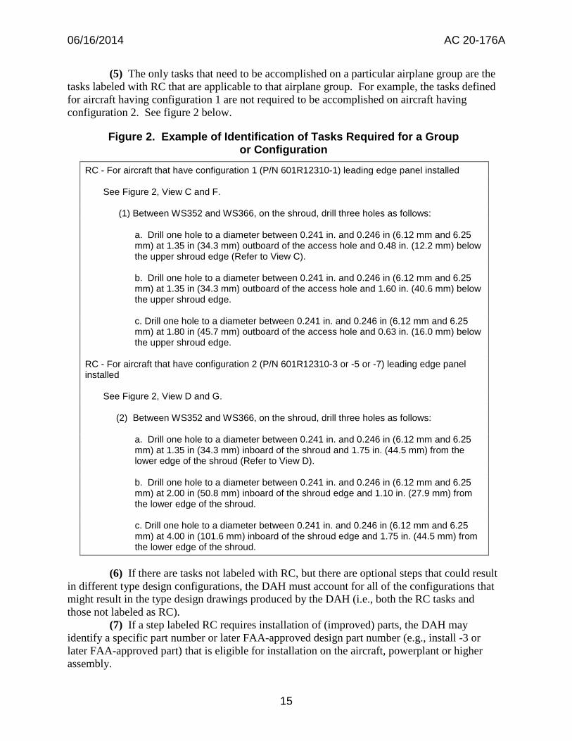
(5) The only tasks that need to be accomplished on a particular airplane group are the tasks labeled with RC that are applicable to that airplane group. For example, the tasks defined for aircraft having configuration 1 are not required to be accomplished on aircraft having configuration 2. See figure 2 below.
Figure 2. Example of Identification of Tasks Required for a Group or Configuration
RC - For aircraft that have configuration 1 (P/N 601R12310-1) leading edge panel installed
See Figure 2, View C and F.
(1) Between WS352 and WS366, on the shroud, drill three holes as follows:
a. Drill one hole to a diameter between 0.241 in. and 0.246 in (6.12 mm and 6.25 mm) at 1.35 in (34.3 mm) outboard of the access hole and 0.48 in. (12.2 mm) below the upper shroud edge (Refer to View C).
b. Drill one hole to a diameter between 0.241 in. and 0.246 in (6.12 mm and 6.25 mm) at 1.35 in (34.3 mm) outboard of the access hole and 1.60 in. (40.6 mm) below the upper shroud edge.
c. Drill one hole to a diameter between 0.241 in. and 0.246 in (6.12 mm and 6.25 mm) at 1.80 in (45.7 mm) outboard of the access hole and 0.63 in. (16.0 mm) below the upper shroud edge.
RC - For aircraft that have configuration 2 (P/N 601R12310-3 or -5 or -7) leading edge panel installed
See Figure 2, View D and G.
(2) Between WS352 and WS366, on the shroud, drill three holes as follows:
a. Drill one hole to a diameter between 0.241 in. and 0.246 in (6.12 mm and 6.25 mm) at 1.35 in (34.3 mm) inboard of the shroud and 1.75 in. (44.5 mm) from the lower edge of the shroud (Refer to View D).
b. Drill one hole to a diameter between 0.241 in. and 0.246 in (6.12 mm and 6.25 mm) at 2.00 in (50.8 mm) inboard of the shroud edge and 1.10 in. (27.9 mm) from the lower edge of the shroud.
c. Drill one hole to a diameter between 0.241 in. and 0.246 in (6.12 mm and 6.25 mm) at 4.00 in (101.6 mm) inboard of the shroud edge and 1.75 in. (44.5 mm) from the lower edge of the shroud.
(6) If there are tasks not labeled with RC, but there are optional steps that could result in different type design configurations, the DAH must account for all of the configurations that might result in the type design drawings produced by the DAH (i.e., both the RC tasks and those not labeled as RC).
(7) If a step labeled RC requires installation of (improved) parts, the DAH may identify a specific part number or later FAA-approved design part number (e.g., install -3 or later FAA-approved part) that is eligible for installation on the aircraft, powerplant or higher assembly.
15
06/16/2014 AC 20-176A
f. Once an SB using the RC concept is IBR’d in an AD:
(1) Any revision to the SB by the DAH will require an AMOC request. This applies even if the SB revision only changes steps that were not labeled RC.
(2) Any substitutions or changes made to the RC steps by owners and operators will require an AMOC (see FAA Order 8110.103, Alternative Method of Compliance, appendix A, paragraph 109). Owner and operator substitutions or changes made to non-RC steps will not require an AMOC if the RC steps can be completed and the aircraft returned to a serviceable condition.
2-11. Streamlining Development and Revision of SBs.
a. Each DAH should have systems in place to continuously monitor and implement process improvements in both the development and revision of SBs. The system should help improve processes involving the quality of SBs as well as reduce flow time to produce those SBs.
b. It is important to remember that any change to an SB, such as a partial or temporary revision, after the SB information is FAA-approved and IBR’d in an AD requires an AMOC approval.
c. Below are examples of process improvements implemented by various DAHs to reduce flow time and improve the quality of SBs. Each DAH should review the list of items and evaluate the feasibility of implementing items from the list, or identify alternatives or equivalents that would improve SB processes.
(1) Use of Checklists and Tip Sheets. Implemented to assist authors in making sure requirements are met before documents are sent for approval.
(2) Use of Templates. Implemented to standardize the location and content of text in SBs, which reduces variation.
(3) Dispute Resolution Process. An informal process where a DAH communicates early and often in the SB process with its regulatory counterpart(s) for early resolution of issues.
(4) Validation Process. A formal process used to validate that the procedures in SBs are accurate, and that hardware kits/parts are complete and can be accomplished per the accomplishment instructions.
(5) Partial Revision Process. A process in which only changed information in an SB is sent to affected customers.
(6) Temporary Revision Process. A process in which only changed information in a document is sent to affected customers. The information is later included in the next scheduled revision cycle for the document.
16
06/16/2014 AC 20-176A
(7) Information Exchange Process. A process in which a DAH shares information used to develop service information. For example, posting the proposed solutions, proposed compliance times, estimated parts availability dates, and other information regarding plans for resolving an unsafe condition on the DAH website. Designated parties can then view the information and provide feedback to the DAH.
(8) Airworthiness Concern Coordination Process. A process in which a DAH, owners, operators, and a regulatory agency work together to develop actions and accomplishment instructions necessary to resolve an unsafe condition. For transport airplanes, a single airline (referred to as the lead airline) reviews the SB and provides comments or recommendations to the DAH prior to the SB publication process.
d. Another way to help facilitate the SB development and revision processes is to use the FAA delegation process. When authorized, a designee can recommend approval of the engineering aspects of an SB that will be the subject of an AD (see FAA Orders 8110.37, Designated Engineering Representative (DER) Handbook, and 8100.15, Organization Designation Authorization Procedures).
2-12. Ex Parté.
a. Ex parté is Latin for “one-sided.” Ex parté contacts are prohibited and can be any oral or written communication between a government employee and someone outside the government regarding the content of a specific rulemaking that excludes other interested parties and takes place before the final rule is published or the NPRM is withdrawn. If ex parté communication occurs, the FAA will place a record of the contact into the AD docket for all parties to view.
b. The FAA’s Airworthiness Directive Manual, FAA-IR-M-8040.1, chapter 3, and 14 CFR part 11, appendix 1, provide information on ex parté communication. Topics include the meaning of an ex parté contact and guidance the FAA must follow during the AD rulemaking process (i.e., prior to/after signatures on AD worksheet, during the comment period, after the comment period closes, and after a meeting is announced to the general public).
17
06/16/2014 AC 20-176A
Chapter 3. Avoiding Overlapping and Conflicting Actions in SBs
3-1. General. This chapter provides a recommended process for DAHs to track AD-related SBs to ensure that they do not contain overlapping or conflicting actions that could lead to a non-compliance with an AD.
3-2. Tracking and Management Process. A DAH should develop a robust SB/AD tracking and management system using the following process to ensure overlaps and conflicts between new and existing SB actions are identified and addressed:
a. Search capabilities should include the following primary areas:
(1) Make/model or part number of affected product(s);
(2) Major aircraft elements (e.g., engine, strut, wing, etc.);
(3) ATA code;
(4) Maintenance zones;
(5) Service information (e.g., SB number);
(6) Airworthiness limitation sections;
(7) Previously issued ADs; and
(8) Planned ADs (i.e., action(s) that the FAA proposes to mandate in an AD).
b. When developing a new SB that will be associated with an AD, the DAH should search for any existing or planned ADs in or affecting the area of the new AD action and determine whether there are potential overlapping and/or conflicting requirements that could lead to non-compliance with any existing AD(s).
c. The DAH should document and maintain a record of its findings.
d. Upon review of the findings, the DAH should resolve any conflicting actions (e.g., the DAH might develop a new design and/or inspection).
e. Finally, the DAH should notify the FAA of the results of its review and resolution of any conflicting issues prior to certification of the new design or issuance of the SB.
18
06/16/2014 AC 20-176A
Chapter 4. AMOCs
4-1. General. This chapter provides guidance to:
a. Owners and operators to share AMOCs with DAHs;
b. DAHs to review FAA-approved AMOCs for an AD to determine if those AMOCs are candidates for a global AMOC;
c. DAHs to consider a process for posting global AMOCs on a website accessible by owners and operators;
d. DAHs to address how to minimize the number of AMOC requests for ADs requiring part changes; and
e. DAHs to develop a process to provide 24/7 AMOC support.
4-2. Sharing AMOCs with DAHs. In order to assist DAHs in identifying AMOCs that might be candidates for a global AMOC, owners and operators requesting an AMOC should consider providing permission to the FAA to share the AMOC approval response (i.e., letter or email) with the product DAH. Written consent must be included in the AMOC proposal submitted to the FAA. The consent must include a statement allowing the FAA to provide the AMOC response to the DAH for consideration as a global AMOC. For example:
Operator XYZ grants the FAA approving office permission to share the AMOC approval response with the Design Approval Holder for consideration in proposing a global AMOC.
4-3. DAH Determination for Global AMOCs.
a. Certain AMOC proposals can be approved as global AMOCs—for example, to use industry best practices that were not previously specified in the AD or IBR’d SB, or to correct typographical errors. As more global AMOCs are FAA-approved and made widely available to owners and operators, their engineering and administrative resource expenditures can be reduced.
b. FAA Order 8110.103 requires the FAA to transmit to the DAH an AMOC approval response when the AMOC proposal includes a consent statement allowing the approval response to be shared. A DAH should review this information and determine if any are candidates for a global AMOC. Refer to 14 CFR 39.19 for information regarding applying for an AMOC (which includes global AMOCs).
(1) If there are similar AMOCs, the DAH should determine if a global AMOC is appropriate, and if so, submit a request for approval of a global AMOC.
(2) If no previous AMOCs exist, the DAH should determine whether the condition is likely to occur on other products of the same type design or in another operator’s fleet. If so,
19
06/16/2014 AC 20-176A
the DAH should submit a request for approval of a global AMOC.
4-4. Posting Global AMOCs on Website. A DAH should consider posting global AMOCs for its products on a website that is accessible by all owners and operators. Making global AMOCs accessible will allow owners and operators to search previously approved global AMOCs that might apply to their product. The posting should include the following:
a. AD number;
b. Model effectivity; and
c. AMOC approval response or subject of AMOC, as appropriate.
4-5. Minimizing AMOC Requests for Part Changes. One way to minimize the number of AMOC requests for ADs requiring part changes is to use “later approved parts” language in the SB. This would allow—without an AMOC approval—installation of DAH parts for compliance with the AD that are FAA-approved after the release of the SB.
a. Use of such language should be on a case-by-case basis. Installation of parts produced by anyone other than the original DAH (e.g., owner or operator-produced parts) will require an AMOC approval.
b. Because owners and operators may not have easy access to information concerning the date a part is approved, SB language for the “later-approved parts” should include recognition that the part complies with the applicable AD. This will ensure owners and operators know which parts are acceptable for installation per the AD.
c. Use the following definition in SBs to define “later-approved parts”:
Later-approved parts are only those [insert name of DAH] parts that are approved as a replacement for the part specified in this service bulletin and approved as part of the type design by the FAA after the issuance of this service bulletin.
d. In order for owners and operators to use later-approved parts without an AMOC approval, the DAH must provide a statement, in writing, to the user of the part that the part’s design was approved after [select either the Original Issue or Revision (X)] of the SB.
e. The Instructions for Continued Airworthiness (ICA), including installation instructions, associated with the later approved part must be acceptable in accordance with 14 CFR 23.1529, 25.1529, 27.1529, 29.1529, 31.82, 33.4, or 35.4, as appropriate.
4-6. 24/7 AMOC Support.
a. In September 2010, the FAA implemented a process to support an urgent need for AMOC issuance after normal business hours to avoid significant air transportation disruptions or substantial impact to an operator. While a 24/7 AMOC support process is available, it is not
20

06/16/2014 AC 20-176A
intended to be used to accommodate air carriers that have failed to adequately plan for AD compliance (see FAA Order 8110.103).
b. To help prevent grounding aircraft due to potential AD non-compliance, a DAH should develop a process for 24/7 AMOC support. Refer to AC 39-9, Airworthiness Directives Management Process, for information on the AD management process for aircraft operators.
21
06/16/2014 AC 20-176A
Chapter 5. Maintaining Compliance with AD-Mandated Design Changes
5-1. General. This chapter provides guidance to DAHs for helping owners and operators and maintenance providers avoid inadvertently undoing or modifying AD-mandated type designs through routine maintenance practices.
5-2. Maintenance of an AD-Mandated Design Change. Once a product’s approved design is changed by an AD, owners and operators may perform routine maintenance if that maintenance does not result in changing the AD-mandated configuration. The maintenance can be performed using a combination of the methods, techniques, and practices prescribed in the DAH maintenance manuals or ICA, or a person’s own maintenance practices developed under 14 CFR 43.13(c).
a. The potential for undoing an AD-mandated configuration should be evaluated during all stages of design and development of SBs, maintenance documents, or ICA (e.g., during the review/approval of the SB, maintenance, and ICA; SB prototyping/validation; and NPRM comment period).
b. To decrease the chances that maintenance will inadvertently undo or modify an AD-mandated type design, the following actions should be performed by DAHs:
(1) During the design change and SB development stages, evaluate the need for changes to maintenance manuals or ICA to eliminate the potential for undoing an AD-mandated condition or configuration. Update any maintenance manuals or ICA to support the AD-mandated type design changes.
(2) Provide awareness to owners and operators regarding availability of updated ICA documents.
(3) When drafting SBs, use notes for flexibility and refer to standard practices as much as possible.
(4) When drafting SBs, avoid duplicating entire procedures and instructions that reside in maintenance or other ICA documents. The SB should only list the specific requirement which must be met, not the entire procedure. Internal flags should then be placed in the associated maintenance document where the requirement is located to indicate that it addresses an AD compliance requirement (see paragraph 5-5).
(5) Create an SB-to-AD cross-reference listing upon release of the AD (see paragraph 5-6).
5-3. Availability of Maintenance Procedures or ICA. A DAH should make new maintenance procedures or ICA3 or changes to them available as early as possible to owners and operators when an AD-related SB is issued (e.g., prior to the effective date of the AD). Doing so helps ensure that owners and operators have the appropriate maintenance procedures
3 Refer to 14 CFR 21.50
22
I I I I
06/16/2014 AC 20-176A
or ICA necessary to maintain the product upon accomplishing or complying with the AD.
5-4. Allowing Flexibility. Include notes and refer to standard practices in SBs when possible. This will help prevent conflicting requirements or configurations from being created, and thereby reduce the likelihood that subsequent maintenance would de-modify the type design mandated by an AD.
5-5. Flagging Procedures. When an SB specifies requirements that exist in a maintenance manual (e.g., an AMM), or when the SB instruction includes language to accomplish a procedure “in accordance with” a manual (see paragraph 2-9) that is approved by a regulatory authority (e.g., the SRM), the requirement or procedure in the manual from which the requirement was duplicated, or the referenced manual, should be flagged by the DAH. The procedure should be flagged in a manner that identifies the procedure or requirement in the manual held by the DAH is mandated by an AD. The flagged language should:
a. Be visible to the maintenance documentation authors for their use (i.e., not on the maintenance documents provided to the owners and operators).
b. Contain a note similar to the following or list the SB and AD number once it becomes available:
“Note: This procedure is used for maintaining compliance with SB XYZ, which is subject to or mandated by an AD. Do not alter this procedure without obtaining a global AMOC approval.”
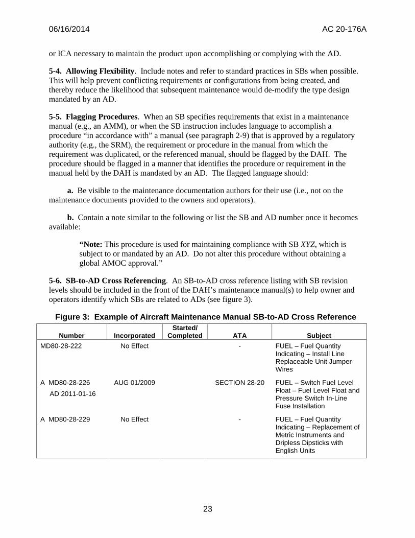
5-6. SB-to-AD Cross Referencing. An SB-to-AD cross reference listing with SB revision levels should be included in the front of the DAH’s maintenance manual(s) to help owner and operators identify which SBs are related to ADs (see figure 3).
Figure 3: Example of Aircraft Maintenance Manual SB-to-AD Cross Reference
Number Incorporated Started/
Completed ATA Subject MD80-28-222
A MD80-28-226 AD 2011-01-16
A MD80-28-229
No Effect
AUG 01/2009
No Effect
-
SECTION 28-20
-
FUEL – Fuel Quantity Indicating – Install Line Replaceable Unit Jumper Wires
FUEL – Switch Fuel Level Float – Fuel Level Float and Pressure Switch In-Line Fuse Installation
FUEL – Fuel Quantity Indicating – Replacement of Metric Instruments and Dripless Dipsticks with English Units
23
06/16/2014 AC 20-176A
Chapter 6. Indicating FAA Approval on Service Documents
6-1. General. This chapter provides guidance on when and how a service document may indicate FAA approval.
6-2. FAA Approval of a Service Document.
a. Within the context of this AC, a service document is defined as a publication that conveys useful information relative to safety, product improvement, and operational or maintenance practices. It does not include type design documents under 14 CFR 21.31, such as flight manuals and certain maintenance manuals.
b. Typically, a service document conveys recommended actions and information related to engineering data that is already FAA-approved. As such, do not mark or imply that an entire service document is approved in total by the FAA, unless total FAA approval is required by regulation and has been granted in accordance with prescribed procedures. In other words, there must be a regulatory basis for indicating FAA approval. For example:
(1) An alteration, parts replacement, repair, etc. that is based upon a design approval (original or revised).
(2) Procedures that will be mandated by an AD to resolve an unsafe condition or an associated AMOC to the AD.
6-3. Indicating FAA Approval.
a. In the past, manufacturers have incorrectly marked entire service documents as “FAA Approved,” “FAA/DER Approved,” “DER Approved,” “DOA Approved,” or “ODA Approved.” Except for the type design data, there is no regulatory basis for FAA approval of other information in service documents. Therefore, only the appropriate page(s) of the document that contain engineering information supporting the original type design or a change to it should indicate FAA approval. The service document should be explicit as to what falls within the scope of FAA approval. For example:
(1) The resultant alteration (or repair) to the affected aircraft described by paragraph XX has been shown to comply with the applicable Federal Aviation Regulations and is FAA Approved.
(2) The retirement life limits of paragraph XX have been shown to comply with the applicable Federal Aviation Regulations and are FAA Approved.
b. Many parts of typical service documents do not require, and should not receive, FAA approval. These parts include, but are not limited to:
(1) Compliance times (except as referenced in an AD);
(2) Background information on the reasons supporting issuance of the document;
24
06/16/2014 AC 20-176A
(3) Manpower estimates to complete an activity;
(4) Recommended maintenance actions, including inspections, that do not require FAA approval;
(5) Step-by-step routine alteration procedures;
(6) Cost of compliance estimates; and
(7) Tooling (not required by type design) and facility requirements.
c. Service document statements regarding approval status should read “FAA Approved” even though FAA designees may have been involved in determining compliance. Terms such as “DER (or UM) Approved,” “FAA/DER Approved,” “ODA Approved,” etc., should not be used in service documents.
6-4. Revisions to Service Documents. Changes to FAA-approved portions of service documents require FAA approval for the changes (or designee approval as appropriate).
25
06/16/2014 AC 20-176A Appendix A
Appendix A. Examples of Notes in SBs
The following are examples of general notes that can be used in an SB:
1. The instructions in Paragraph 3.B. l., Work Instructions and the figures can include operation of tools or test equipment. {Specify appropriate document} contain data on versions of the tools or test equipment that you can use. It is permitted to use replaced tools. It is not permitted to use superseded tools.
2. If it is necessary to remove more parts for access, you can remove those parts. If you can get access without removing identified parts, it is not necessary to remove all of the identified parts. Jacking and shoring limitations must be observed.
3. If the length of any fastener specified in this service bulletin does not meet installation standards given in SRM Chapter 51, then a fastener of the same specification, or an approved substitute, with a length which meets the installation standards given in SRM Chapter 51 may be used. In addition, washers may be installed for fastener grip length in accordance with SRM Chapter 51.
4. Where the work instructions include installation of a kept part, a new or serviceable part with the same part number can be installed as an alternative to the kept part.
5. This service bulletin includes functional test procedures for the systems changed by this service bulletin. More functional tests can possibly be necessary in accordance with standard maintenance practices because of interruption to other airplane systems.
6. Some {Specify DAH name} parts are supplied in a temporary configuration. Those parts are identified with a “U”, “W”, or “Y” in place of the “-“ (dash) in the part number. It is permitted to install parts identified with a “U”, “W”, or “Y” as an alternative to the “-“ (dash) part number. {Specify document/drawing} contains more data.
A-1
06/16/2014 AC 20-176A Appendix B
Appendix B. Examples of Notes that Provide Flexibility in SBs
The following are examples of notes that can be used in an SB to allow flexibility:
1. The instructions identified in Paragraph 3.B., Work Instructions and the Figure(s) give the recommended sequence of steps. The sequence of steps may be completed first on either the right side or left side of the aircraft .
2. Equivalent parts are listed in drawing {drawing number}.
3. Refer to SRM Chapter 51 for approved fasteners and process material substitutions.
4. If the length of any fastener specified in this service bulletin does not meet the installation standards in SRM Chapter 51, then a fastener of the same specification, or an approved substitute, with a length which meets the installation standards in Chapter 51 may be used.
5. A 1/8-inch stack of the same type washers called for in this service bulletin is the maximum thickness which may be used under the fastener head or not to counteract accumulation of tolerances. EXCEPTION: When the available fastener length increments are greater than 1/16inch, a 3/16-inch thick stack of the same type washers may be used.
6. Unless shown differently, these dimensions and tolerances are used:
a. Linear dimensions are in inches.
b. Tolerance on linear dimensions, other than rivet and bolt edge margins, is plus or minus 0.03 inch.
c. Tolerance on rivet and bolt edge margin is plus or minus 0.05 inch.
d. Angular tolerance is plus or minus 2 degrees.
e. Hole dimensions for standard solid rivets are in {airplane model} SRM, Chapter 51.
f. Torque limits to tighten nuts and bolts are in {airplane model} SRM, Chapter 51.
7. The work instructions are divided into work packages. Task Hours and Elapsed Hours for each package are given in Paragraph 1.G., Manpower. You can do each work package independently.
8. Refer to the SWPM 20-10-01 as accepted wire installation procedures.
9. Refer to these SWPM chapters for applicable operations, as accepted procedures {list applicable SWPM chapters}.
10. Refer to {airplane model} AMM 20-15-11 for on-airplane software installation maintenance practices and data transfer times as accepted procedures.
B-1
06/16/2014 AC 20-176A Appendix B
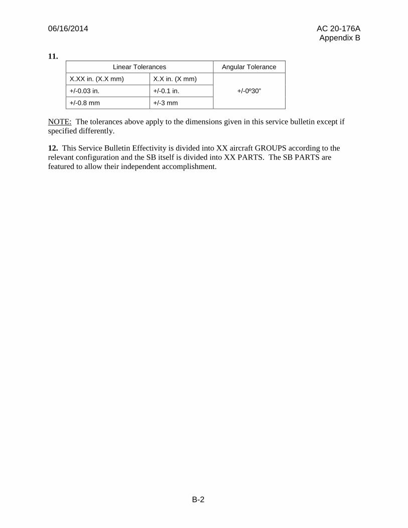
11. Linear Tolerances Angular Tolerance
X.XX in. (X.X mm) X.X in. (X mm)
+/-0º30” +/-0.03 in. +/-0.1 in.
+/-0.8 mm +/-3 mm
NOTE: The tolerances above apply to the dimensions given in this service bulletin except if specified differently.
12. This Service Bulletin Effectivity is divided into XX aircraft GROUPS according to the relevant configuration and the SB itself is divided into XX PARTS. The SB PARTS are featured to allow their independent accomplishment.
B-2
0 LEGEND
1. Inboard MLG door. 3. Fwd member. -4. OVter skin .. s. oos.s member. 7. An member. 9. OUterdoubler,
NOTES
1 Shaded areas are · to be examined.
2. Oulboaril MLG door noc $hown tor e1anfy,
5
4
,
©
® LEFT SIDE SHOWN
RIGHT SIDE OPPOSITE
1
OUTSOARO MLGDOOR (REF)
06/16/2014 AC 20-176A Appendix C
Appendix C. Examples of Concepts to Clarify Illustrations
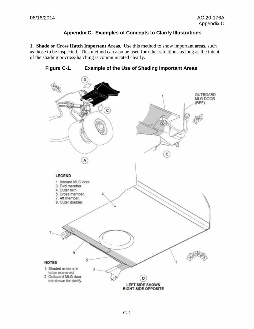
1. Shade or Cross Hatch Important Areas. Use this method to show important areas, such as those to be inspected. This method can also be used for other situations as long as the intent of the shading or cross-hatching is communicated clearly.
Figure C-1. Example of the Use of Shading Important Areas
C-1
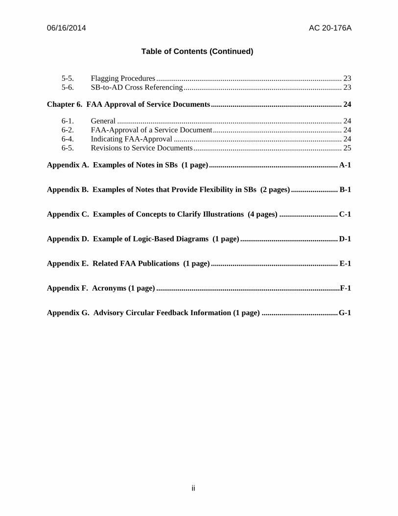
D
0 WASHER ----, PN NAS1149FNl32P (REMOVE AND DISCARD)
DET. D (PRE-MOD)
0 BOLT (2 POSITIONS) PN NAS1091>-2•8 (REMOVE AND DISCARD)
0 ----- WASHER (2 POSITIONS)
PN NAS1149FN832P (REMOVE AND DISCARD)
0 MICROSW!TCH SUPPORT ASSY PN 145-40193-401 (REMOVE AND DISCARD)
06/16/2014 AC 20-176A Appendix C
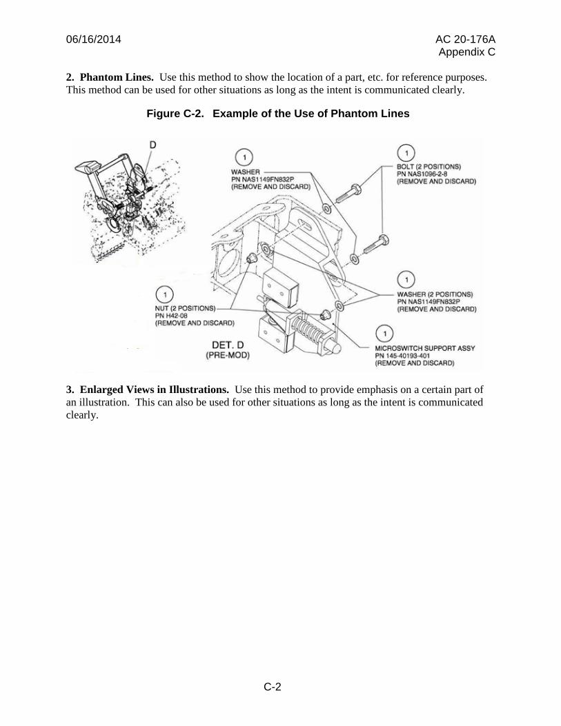
2. Phantom Lines. Use this method to show the location of a part, etc. for reference purposes. This method can be used for other situations as long as the intent is communicated clearly.
Figure C-2. Example of the Use of Phantom Lines
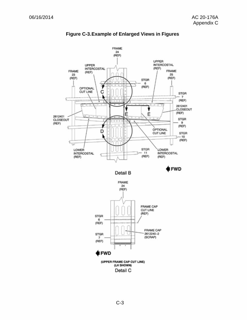
3. Enlarged Views in Illustrations. Use this method to provide emphasis on a certain part of an illustration. This can also be used for other situations as long as the intent is communicated clearly.
C-2
FRAME •• (JIEF)
1.FPER I llfT'ERCOSTAL n+n
UPl'ER INfEACOSTAL (REF)
(REF) l~ I ,- : ,; U :,;, STGR
FRAME .. (JIEF)
...... .;-·+ •t ~ - 6 I OPTIONAL (REF) CUTUNE
LOWER INTERCOSTAL l"EF)
STGR
• (JIEF)
STOil 7
(JIEF)
STGR 7
(REF) . . -· ....... 261240 1 L -1..,_CLOSE:OUT
(IS)
STGR - . STOil
t::::>- 11 (JIEF)
OPTIONAL Cl/TUNE
LOWER INTEFIOOSTAl (REF)
(REF)
STGR 10
(REF)
Detail B . FWD
FRAME 24
(JIEF)
,,I i,-~. -
:n -~ n: : : ; i l : :: : V 1,..: 1..;: •-·-·+o-·-·-·4 .
u~••••••••H••'••
FRAME CAP CUT LINE (JIEF)
I +----·: if"' n ni : , : . ~·-!i--1---- FRAME CAP
,_i_k,: •• ~·L;":.:i., 2612240p2 ,., _,,,, .. ,,,,, .. \SCRAP) . . -.
(VPPE.R FRAME CAP CUT UNE} (l.H SHOWN)
Detail C
06/16/2014 AC 20-176A Appendix C
Figure C-3.Example of Enlarged Views in Figures
C-3
D-D
06/16/2014 AC 20-176A Appendix C
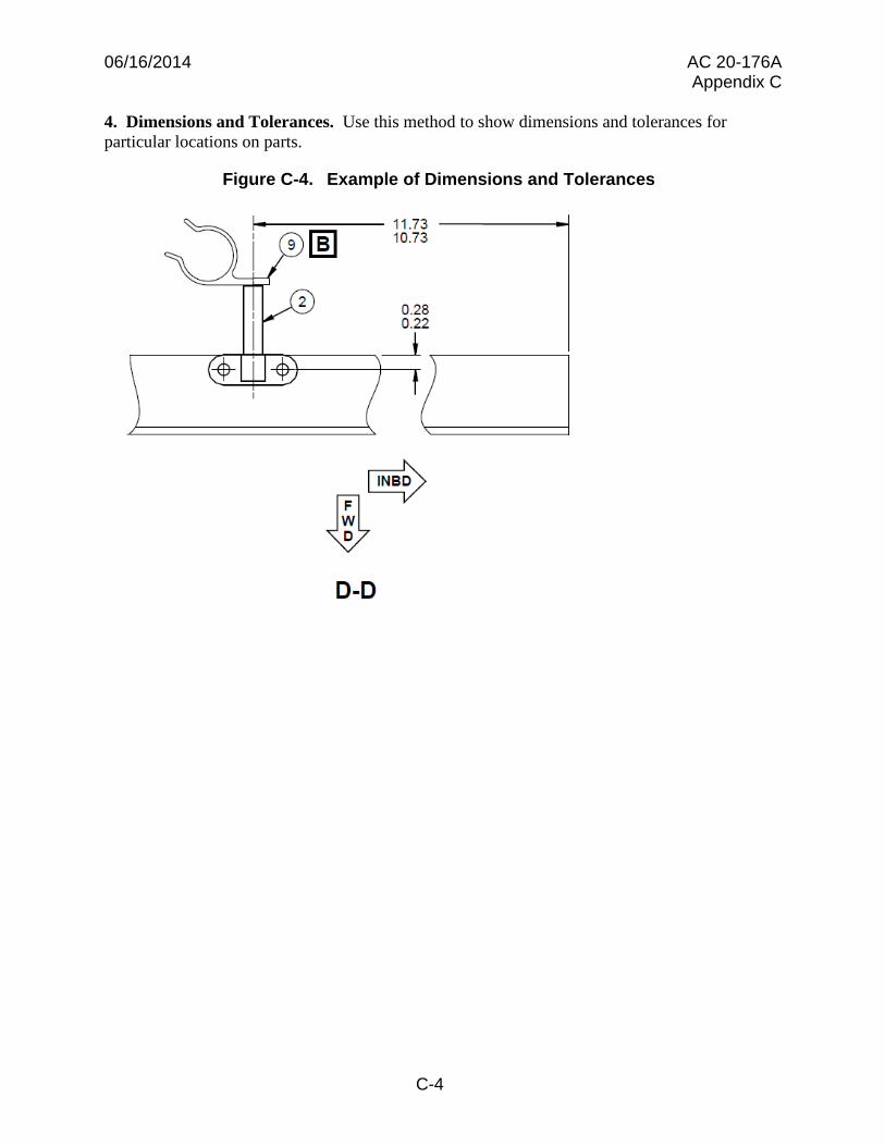
4. Dimensions and Tolerances. Use this method to show dimensions and tolerances for particular locations on parts.
Figure C-4. Example of Dimensions and Tolerances
C-4
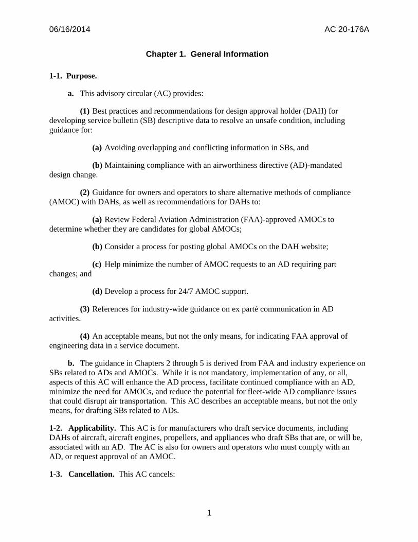
WITHIN &.lOO FLIGHT CYCLES LNSPECT THE YOKE A SSEMBLY AHO
THE PCU LUG FOR DAMAGE
l l
DAMAGE NODAIAAGE FOUND FOUND
I l l NO DAt..iAGE TO PCU
BUT YOKE ASSEMBLY NICKS AND'OR REP EAT THE
HAS VISUAL BEARING GAUGES F OUND FRETTING REPLACE INSPECTION ROTA.TtON OR ON P CU LU G BUT DAMAGE TO YOKE WITI-IIN 500
,_ MIGRATION, SIGNS OF t~O FRETTING PCU LUGS ASSEMBl.Y FLIGHT
WEARTOA.NTI DAMAGE TO PCU CYCLES
ROTATION LUGS OR LUG
FRi:ITU4G
1 REPLACE REPLACE REMOVEPCU
YOKE YOKE ANO REPAIR OR ASSEMBLY ASSEMBLY REPLACE THE
BEFORE WITHIN 3000 PCUBEFORE FURTH ER F LIGHT FURTH ER
FLIGHT CYCLES FLIGHT
I l
REPEAT TH E INSPECTION WfTHIN 3000
FLIGHT CYCLES
06/16/2014 AC 20-176A Appendix D
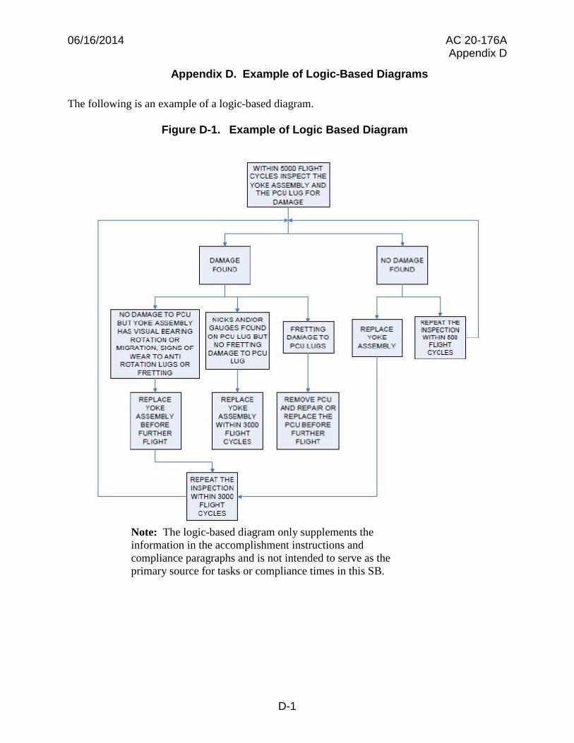
Appendix D. Example of Logic-Based Diagrams
The following is an example of a logic-based diagram.
Figure D-1. Example of Logic Based Diagram
Note: The logic-based diagram only supplements the information in the accomplishment instructions and compliance paragraphs and is not intended to serve as the primary source for tasks or compliance times in this SB.
D-1
06/16/2014 AC 20-176A Appendix E
Appendix E. Related FAA Publications
1. Where to Find Publications. Publications referenced throughout this document refer to the latest revision level. You can get copies from the FAA Web site at http://www.faa.gov/ and our Regulatory and Guidance Library (RGL) at http://rgl.faa.gov.
a. FAA AC 39-9, Airworthiness Directives Management Process
b. FAA Orders.
(1) Order 8100.15, Organization Designation Authorization Procedures
(2) Order 8110.37, Designated Engineering Representative (DER) Handbook
(3) Order 8110.103, Alternative Methods of Compliance (AMOC)
c. DOT Order 2100.2, Policies for Public Contacts in Rulemaking
d. FAA Manual FAA-IR-M-8040.1, Airworthiness Directives Manual
E-1
06/16/2014 AC 20-176A Appendix F
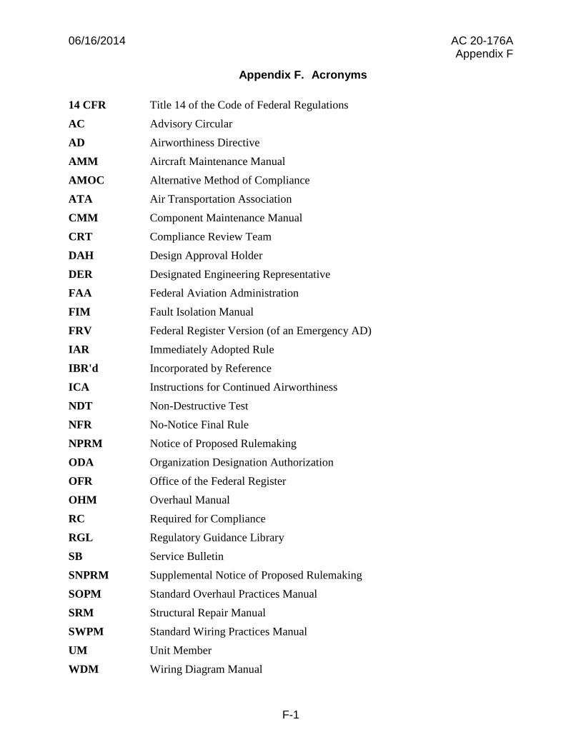
Appendix F. Acronyms
14 CFR Title 14 of the Code of Federal Regulations
AC Advisory Circular
AD Airworthiness Directive
AMM Aircraft Maintenance Manual
AMOC Alternative Method of Compliance
ATA Air Transportation Association
CMM Component Maintenance Manual
CRT Compliance Review Team
DAH Design Approval Holder
DER Designated Engineering Representative
FAA Federal Aviation Administration
FIM Fault Isolation Manual
FRV Federal Register Version (of an Emergency AD)
IAR Immediately Adopted Rule
IBR'd Incorporated by Reference
ICA Instructions for Continued Airworthiness
NDT Non-Destructive Test
NFR No-Notice Final Rule
NPRM Notice of Proposed Rulemaking
ODA Organization Designation Authorization
OFR Office of the Federal Register
OHM Overhaul Manual
RC Required for Compliance
RGL Regulatory Guidance Library
SB Service Bulletin
SNPRM Supplemental Notice of Proposed Rulemaking
SOPM Standard Overhaul Practices Manual
SRM Structural Repair Manual
SWPM Standard Wiring Practices Manual
UM Unit Member
WDM Wiring Diagram Manual
F-1
_____________________________________________________________________________
_____________________________________________________________________________
_______________________________________________________________________
_______________________________________________________________________
06/16/2014 AC 20-176A Appendix G
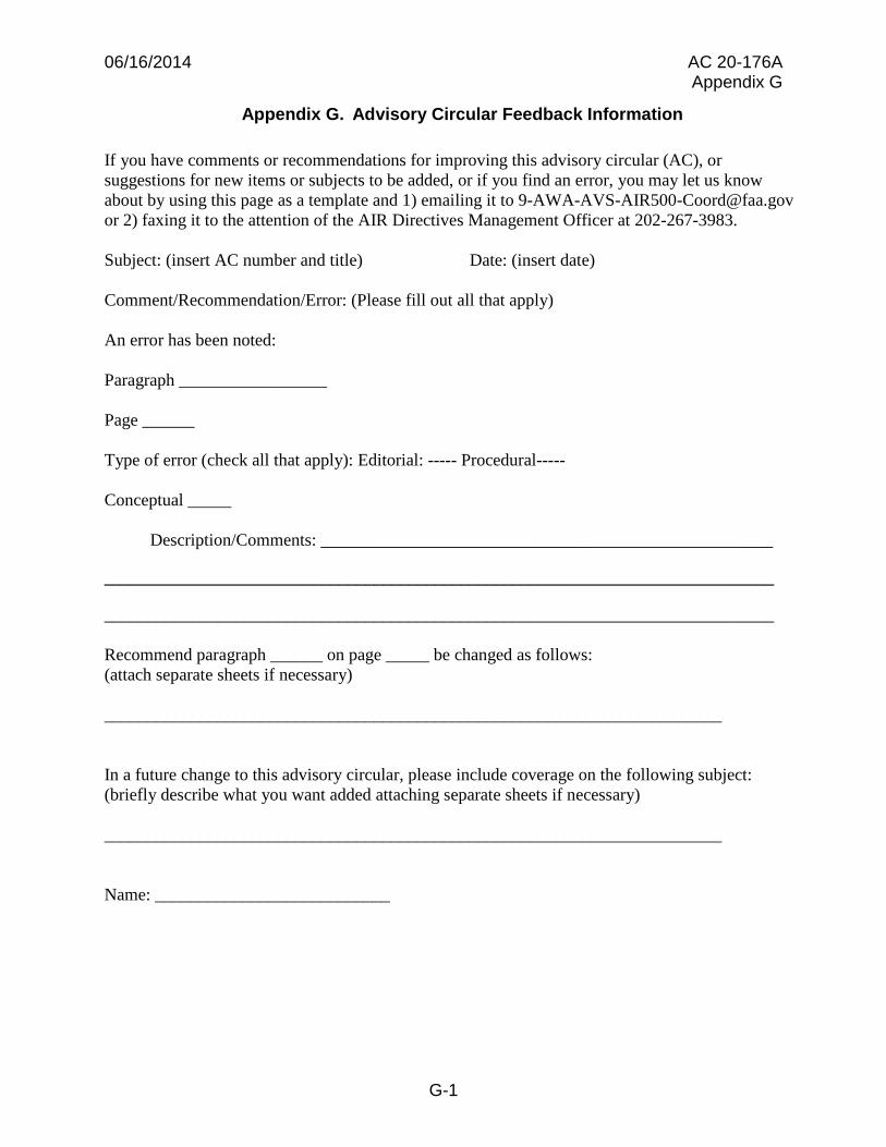
Appendix G. Advisory Circular Feedback Information
If you have comments or recommendations for improving this advisory circular (AC), or suggestions for new items or subjects to be added, or if you find an error, you may let us know about by using this page as a template and 1) emailing it to [email protected] or 2) faxing it to the attention of the AIR Directives Management Officer at 202-267-3983.
Subject: (insert AC number and title) Date: (insert date)
Comment/Recommendation/Error: (Please fill out all that apply)
An error has been noted:
Paragraph _________________
Page ______
Type of error (check all that apply): Editorial: ----- Procedural----
Conceptual _____
Description/Comments: ____________________________________________________
Recommend paragraph ______ on page _____ be changed as follows: (attach separate sheets if necessary)
In a future change to this advisory circular, please include coverage on the following subject: (briefly describe what you want added attaching separate sheets if necessary)
Name: ___________________________
G-1