Embed Size (px)
Citation preview
AdvisoryU.S. Department of Transportation CircularFederal Aviation Administration
Subject: SPECIFICATION FOR AIRPORT Date: October 17, 2006 AC No: AC 150/5345-42FLIGHT BASES, TRANSFORMER HOUSINGS, JUNCTION BOXES, AND ACCESSORIES Initiated by: AAS-100 Change:
1. PURPOSE. This advisory circular (AC) contains the specifications for containers designed to serve as airport light bases, transformer housings, junction boxes, and accessories. This AC is not intended to be a compilation of currently available product designs. This AC provides the basic standard requirements for critical dimensions and performance requirements to which all manufacturers must demonstrate compliance.
2. EFFECTIVE DATE. Effective October 17, 2006, only that equipment qualified in accordance with this specification will be listed in AC 150/5345-53, Airport Lighting Equipment Certification Program.
a. Manufacturers who, prior to the effective date of this AC, were certified manufacturers of Class I, Type L-867 and Type L-868 bases and extensions under AC 150/5345-42C may maintain their certification under this new AC for the Class IA providing they satisfactorily complete any additional qualification testing required as part of this AC.
b. Manufacturers who, prior to the effective date of this AC, were certified manufacturers of Class II, Type L-867 bases and extensions under AC 150/5345-42C may maintain their certification under this new AC for Class IIA providing they satisfactorily complete any additional qualification testing required as part of this AC.
c. Manufacturers who, prior to the effective date of this AC, were certified manufacturers of metallic Class II, Type L-867 and Type L-868 bases and extensions under AC 150/534542C may maintain their certification under this new AC for Class IA providing they satisfactorily complete any additional qualification testing required as part of this AC.
d. Manufacturers who were certified to manufacture 10 inch (254 mm) diameter Type L-868 bases may maintain their 150/5345-42C certification listing for spacers and extensions under Class IA in this revised AC in order to service those airports with existing 10 inch (254 mm) diameter taxiway centerline fixtures. These items must be fabricated and certified to the appropriate Class as defined in this AC. Appendix figure A-1 provides the design dimensional details. New base installations should not have 10 inch (254 mm) diameter L-868 bases.
3. CANCELLATION. AC 150/5345-42E, Specification for Airport Light Bases, Transformer Housings, Junction Boxes, and Accessories, dated May 8, 2006, is canceled.
4. APPLICATION. The specifications contained in this AC are recommended by the Federal Aviation Administration (FAA) in all applications involving development of this nature. For
airport projects receiving Federal funds under the airport grant assistance program, the use of these standards is mandatory.
5. PRINCIPAL CHANGES FROM 42E:
a. Figure 8, increase inner diameter of extension bottom flange from 9.25 inches to 10 inches.
b. Figure A-1, decrease outer diameter of spacer ring from 10.5 inches to 10 inches.
c. Rescind torque testing of L-867s by deleting paragraphs 4.1.7 and 4.2.8.
d. Reduce required cycles for fatigue testing from 5 × 10⁸ to 5 × 10⁷.
6. METRIC UNITS. To promote an orderly transition to metric units, this AC includes both English and metric dimensions. The metric conversions may not be exact equivalents, and until there is an official changeover to the metric system, the English dimensions will govern.
7. COMMENTS OR SUGGESTIONS for improvements to this AC should be sent to:
Manager, Airport Engineering Division Federal Aviation Administration ATTN: AAS-100 800 Independence Avenue, S.W.Washington, DC 20591
8. COPIES OF THIS AC. The Office of Airport Safety and Standards is in the process of making ACs available to the public through the Internet. These ACs may be found through the FAA home page (www.faa.gov). A printed copy of this AC and other ACs can be ordered from the U.S. Department of Transportation, Subsequent Distribution Office, Ardmore East Business Center, 3341 Q 75th Avenue, Landover, MD 20785.
DAVID L. BENNETT Director of Airport Safety and Standards
October 17, 2006 AC 150/5345-42F
TABLE OF CONTENTS
SECTION 1. SCOPE ................................................................................................................... 11.1 Type. ................................................................................................................................... 1 1.2 Class.................................................................................................................................... 1 1.3 Size...................................................................................................................................... 2
SECTION 2. APPLICABLE DOCUMENTS............................................................................ 32.1 FAA Advisory Circulars. .................................................................................................... 3 2.2 Military Standard and Specification. .................................................................................. 3
2.2.1 Military Standard. ...................................................................................................... 32.2.2 Military Specification. ............................................................................................... 3
2.3 American Society for Testing and Materials (ASTM) Specifications, Test Methods, Standard Practices, and Recommended Practices......................................................... 3
2.4 American Society of Mechanical Engineers (ASME). ....................................................... 4 2.5 American Society for Quality Control (ASQC).................................................................. 4 2.6 Miscellaneous Documents. ................................................................................................. 4
SECTION 3. REQUIREMENTS................................................................................................ 53.1 General Description and Intended Use. .............................................................................. 5
3.1.1 Type L-867 Bases. ..................................................................................................... 5 3.1.2 Type L-868 Bases. ..................................................................................................... 5 3.1.3 General Accessories................................................................................................... 5
3.2 Fabrication and Materials. .................................................................................................. 73.2.1 Type L-867, Class IA and Class IB Bases and Extensions........................................ 7 3.2.2 Type L-867, Class IIA and Class IIB Bases and Extensions..................................... 9 3.2.3 Type L-867 Accessories. ......................................................................................... 10 3.2.4 Type L-868, Class IA and Class IB Bases and Extensions...................................... 10 3.2.5 Type L-868 Accessories. ......................................................................................... 12 3.2.6 Grounding Lugs. ...................................................................................................... 12 3.2.7 Drains. ................................................................................................................... 12 3.2.8 Protective Coating.................................................................................................... 12
SECTION 4. QUALITY ASSURANCE PROVISIONS ........................................................ 134.1 Type L-867, Class IA and Class IB Certification Testing. ............................................... 13
4.1.1 Type L-867, Class IA and Class IB Load Test. ....................................................... 13 4.1.2 Type L-867, Class IA and Class IB Weld Integrity Test. ........................................ 14 4.1.3 Type L-867, Class IA and Class IB Dimensional Tests. ......................................... 14 4.1.4 Type L-867, Class IA and Class IB Protective Coating Thickness Test. ................ 14 4.1.5 Type L-867, Class IA and Class IB Visual Inspection. ........................................... 14 4.1.6 Type L-867, Class IB Potassium Acetate Test. ....................................................... 14
4.2 Type L-867, Class IIA and Class IIB Certification Testing. ............................................ 14 4.2.1 Type L-867, Class IIA and Class IIB Load Test. .................................................... 14 4.2.2 Type L-867, Class IIA and Class IIB Weld Integrity Test. ..................................... 15 4.2.3 Type L-867, Class IIA and Class IIB Temperature Shock Test. ............................. 15 4.2.4 Type L-867, Class IIA and Class IIB Dimensional Tests........................................ 15 4.2.5 Type L-867, Class IIA and Class IIB Protective Coating Thickness Test............... 15
i
AC 150/5345-42F October 17, 2006
4.2.6 Type L-867, Class IIA and Class IIB Visual Inspection. ........................................ 15 4.2.7 Type L-867, Class IIB Potassium Acetate Test. ...................................................... 15
4.3 Type L-868, Class IA and Class IB Certification Testing. ............................................... 15 4.3.1 Type L-868, Class IA and Class IB Load Test. ....................................................... 15 4.3.2 Type L-868, Class IA and Class IB Fatigue Test. .................................................. 15 4.3.3 Type L-868, Class IA and Class IB Impact Test. .................................................... 16 4.3.4 Type L-868, Class IA and Class IB Flange Bolt Torque Test. ................................ 16 4.3.5 Type L-868, Class IA and Class IB Weld Integrity Test. ........................................ 16 4.3.6 Type L-868, Class IA and Class IB Dimensional Tests. ......................................... 16 4.3.7 Type L-868, Class IA and Class IB Protective Coating Thickness Test. ................ 16 4.3.8 Type L-868, Class IA and Class IB Visual Inspection. ........................................... 16 4.3.9 Type L-868, Class IB Potassium Acetate Test. ....................................................... 16 4.3.10 Type L-868, Class IA and Class IB Torque Test for Adjustable Height Bases and
Extensions. ................................................................................................ 16 4.4 Production Testing............................................................................................................ 17
4.4.1 Lot Size. ................................................................................................................... 17 4.4.2 Sample Size and Acceptance Criteria. ..................................................................... 17 4.4.3 Retesting. ................................................................................................................. 17 4.4.4 Type L-867, Class IA and Class IB. ........................................................................ 17 4.4.5 Type L-867, Class IIA and Class IIB....................................................................... 17 4.4.6 Type L-868, Class IA and Class IB. ........................................................................ 17
SECTION 5. PREPARATION FOR DELIVERY.................................................................. 195.1 Packing.............................................................................................................................. 19 5.2 Marking............................................................................................................................. 19
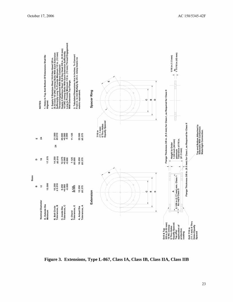
LIST OF FIGURES Figure 1. Flange, Type L-867, Class IA, Class IB, Class IIA, Class IIB .................................... 21 Figure 2. Body, Type L-867, Class IA, Class IB, Class IIA, Class IIB....................................... 22 Figure 3. Extensions, Type L-867, Class IA, Class IB, Class IIA, Class IIB.............................. 23 Figure 4. Accessories, Type L-867.............................................................................................. 24 Figure 5. Flange, Type L-868, Class IA, Class IB....................................................................... 25 Figure 6. Body, Type L-868, Class IA, Class IB......................................................................... 26 Figure 7. Sectional Body, Type L-868, Class IA, Class IB......................................................... 27 Figure 8. Extensions, Type L-868 Class IA, Class IB................................................................. 28 Figure 9. Accessories, Type L-868.............................................................................................. 29 Figure A-1. Extensions and spacers for 10-inch (254 mm) Diameter Type L-868 base, for
Maintenance of Existing Installations Only......................................................................... A-1
ii
October 17, 2006 AC 150/5345-42F
SECTION 1. SCOPE
This specification sets forth the requirements for light bases, transformer housings, junction boxes, and related accessories. This specification covers several types, classes, and sizes of bases.
1.1 Type. The type designation of the bases and extensions distinguishes their application as follows:
Type L-867 Bases and extensions for applications subject to occasional light vehicular loading but no aircraft or other heavy vehicular loading.
Type L-868 Bases and extensions for applications subject to aircraft and other heavy vehicular loading.
1.2 Class. The class designation applies as follows:
Class IA Bases and extensions that are fabricated from metal in exact conformance to the critical dimensions and requirements necessary for standardization between parts specified herein.
Class IB Bases and extensions that are fabricated from metal in exact conformance to the critical dimensions and requirements necessary for standardization between parts specified herein and which have been subjected to corrosion testing and found resistant to deicing fluids containing potassium acetate.
Class IIA Bases and extensions that are fabricated from non-metallic materials in exact conformance to the critical dimensions and requirements necessary for standardization between parts specified herein.
Class IIB Bases and extensions that are fabricated from non-metallic materials in exact conformance to the critical dimensions and requirements necessary for standardization between parts specified herein and which have been subjected to corrosion testing and found resistant to deicing fluids containing potassium acetate.
Note 1 Bases and extensions that meet the Class IB or Class IIB requirements are also considered to meet Class IA or Class IIA requirements, respectively.
Note 2 Bases and extensions that are fabricated as either Class IA or Class IB are to perform the same exact function. The only difference between the two classes of bases and extensions is the possible difference in metal or metal surface treatment required to meet the Class IB level of testing.
Note 3 Bases and extensions that are fabricated as either Class IIA or Class IIB are to perform the same exact function. The only difference between the two bases and extensions is the possible difference in material or material surface treatment required to meet the Class IIB level of testing.
1
AC 150/5345-42F October 17, 2006
1.3 Size. Five base size designations are assigned. The size refers to the nominal diameter of the base. Sizes and applicable types are as follow:
Size Type Size A - 8 inch (203 mm) Type L-868
Size B - 12 inch (305 mm) Type L-867 and Type L-868
Size C - 15 inch (381 mm) Type L-868
Size D - 16 inch (406 mm) Type L-867
Size E - 24 inch (610 mm) Type L-867
2
October 17, 2006 AC 150/5345-42F
SECTION 2. APPLICABLE DOCUMENTS
The following documents are referenced or complement the information presented in this AC:
2.1 FAA Advisory Circulars. The FAA AC listed below contains information pertinent to this specification. Copies of the current edition of the AC may be obtained at no charge from the following FAA website:
http://www.faa.gov/
AC 150/5340-30 Design and Installation Details for Airport Visual Aids
2.2 Military Standard and Specification. The following Military Standard and Specification (in effect on the date of application for qualification) form a part of this specification and are applicable to the extent specified herein. Copies of military standards and specifications may be obtained at no charge from: DoDSSP, Building 4, Section D, 700 Robbins Ave, Philadelphia, PA 19111-5098, or from the following website:
http://dodssp.daps.mil/
2.2.1 Military Standard. MIL-STD-810 Environmental Engineering Considerations and Laboratory
Tests
2.2.2 Military Specification.
MIL-PRF-26915 Primer Coating, for Steel Surfaces
2.3 American Society for Testing and Materials (ASTM) Specifications, Test Methods, Standard Practices, and Recommended Practices. The following specifications, test methods, standard practices, and recommended practices (in effect on the date of application for qualification) form a part of this specification and are applicable to the extent specified herein. Copies of ASTM specifications, test methods, and recommended practices may be obtained from the American Society for Testing and Materials, or from the website:
http://www.astm.org/
A 36 Standard Specification for Carbon Structural Steel
A 123/A 123M-02 Standard Specification for Zinc (Hot-Dip Galvanized) Coatings on Iron and Steel Products
A 153 Standard Specification for Zinc Coating (Hot-Dip) on Iron and Steel Hardware
A 385-03 Standard Practice for Providing High-Quality Zinc Coatings (Hot-Dip)
B 633 Standard Specification for Electrodeposited Coatings of Zinc on Iron and Steel
C 109 Test Method for Compressive Strength of Hydraulic Cement Mortars
C 617 Standard Practice for Capping Cylindrical Concrete Specimens
3
AC 150/5345-42F October 17, 2006
C 827 Early Volume Change of Cementitious Mixtures
D 2240 Standard Test Hardness
Method for Rubber Property-Durometer
E 23 Standard Test Methods for Notched Bar Impact Testing of Metallic Materials
2.4 American Society of Mechanical Engineers (ASME). The following standard (in effect on the date of application for qualification) forms a part of this specification and is applicable to the extent specified herein. Copies of ASME standards may be obtained from the American Society of Mechanical Engineers, or from the website:
http://www.asme.org/
B46.1 Surface Texture, Surface Roughness, Waviness and Lay
2.5 American Society for Quality Control (ASQC). The following standard (in effect on the date of application for qualification) forms a part of this specification and is applicable to the extent specified herein. Copies of ASQC standards may be obtained from the American Society for Quality Control, or from the website:
http://www.asqc.org/
Z1.4 Sampling Procedures and Tables for Inspection by Attributes
2.6 Miscellaneous Documents. The Design, Installation and Maintenance of In-Pavement Airport Lighting by Arthur S. Schai, F.I.E.S. Library of Congress Catalog Card Number 86-81865. This document does not form a part of this specification but is listed as valuable resource material on the design and installation of light bases. (Reference AC 150/5340-30 for installation details and options.)
4
October 17, 2006 AC 150/5345-42F
SECTION 3. REQUIREMENTS
3.1 General Description and Intended Use. 3.1.1 Type L-867 Bases. Type L-867 is used as a mounting base for airport lights, as a transformer housing and as an electrical junction box. The Type L-867 base must be designed to withstand occasional light vehicular loads. It is subject to direct earth burial with and without concrete backfill. 3.1.2 Type L-868 Bases. Type L-868 is used as a mounting base for in-pavement airport lights, as housing for series circuit transformers, and as an electrical junction box. It must be designed to withstand aircraft and other heavy vehicular loadings. The design must allow the installation of any in-pavement fixture.
The Type L-868 top flange and base must be designed to meet the dimensional requirements and performance requirements, as detailed in this document, in order to assure proper mating between base and in-pavement lighting fixture.
3.1.3 General Accessories. Accessories are used to make corrections, and adjustments to Type L-867 and Type L-868 bases, and to facilitate proper performance of the lighting fixture which the base supports. Examples of accessories are listed below, and when used in conjunction with a base specified in this AC, must not reduce the performance capabilities of that base.
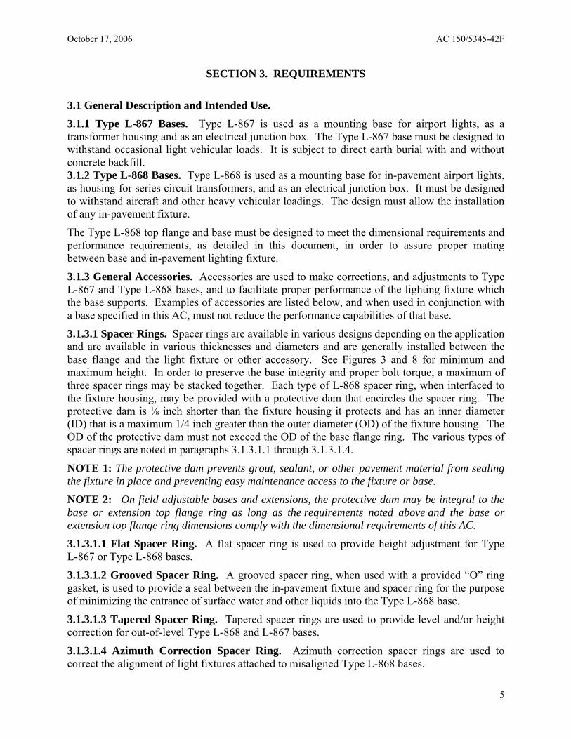
3.1.3.1 Spacer Rings. Spacer rings are available in various designs depending on the application and are available in various thicknesses and diameters and are generally installed between the base flange and the light fixture or other accessory. See Figures 3 and 8 for minimum and maximum height. In order to preserve the base integrity and proper bolt torque, a maximum of three spacer rings may be stacked together. Each type of L-868 spacer ring, when interfaced to the fixture housing, may be provided with a protective dam that encircles the spacer ring. The protective dam is ⅛ inch shorter than the fixture housing it protects and has an inner diameter (ID) that is a maximum 1/4 inch greater than the outer diameter (OD) of the fixture housing. The OD of the protective dam must not exceed the OD of the base flange ring. The various types of spacer rings are noted in paragraphs 3.1.3.1.1 through 3.1.3.1.4.
NOTE 1: The protective dam prevents grout, sealant, or other pavement material from sealing the fixture in place and preventing easy maintenance access to the fixture or base.
NOTE 2: On field adjustable bases and extensions, the protective dam may be integral to the base or extension top flange ring as long as the requirements noted above and the base or extension top flange ring dimensions comply with the dimensional requirements of this AC.
3.1.3.1.1 Flat Spacer Ring. A flat spacer ring is used to provide height adjustment for Type L-867 or Type L-868 bases.
3.1.3.1.2 Grooved Spacer Ring. A grooved spacer ring, when used with a provided “O” ring gasket, is used to provide a seal between the in-pavement fixture and spacer ring for the purpose of minimizing the entrance of surface water and other liquids into the Type L-868 base.
3.1.3.1.3 Tapered Spacer Ring. Tapered spacer rings are used to provide level and/or height correction for out-of-level Type L-868 and L-867 bases.
3.1.3.1.4 Azimuth Correction Spacer Ring. Azimuth correction spacer rings are used to correct the alignment of light fixtures attached to misaligned Type L-868 bases.
5
AC 150/5345-42F October 17, 2006
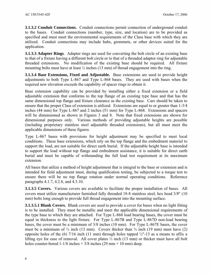
3.1.3.2 Conduit Connections. Conduit connections permit connection of underground conduit to the bases. Conduit connections (number, type, size, and location) are to be provided as specified and must meet the environmental requirements of the Class base with which they are utilized. Conduit connections may include hubs, grommets, or other devices suited for the application.
3.1.3.3 Adapter Rings. Adapter rings are used for converting the bolt circle of an existing base to that of a fixture having a different bolt circle or to that of a threaded adaptor ring for adjustable threaded extensions. No modification of the existing base should be required. All fixture mounting bolts must have at least ½ inches (13 mm) of thread engagement into the ring.
3.1.3.4 Base Extensions, Fixed and Adjustable. Base extensions are used to provide height adjustments to both Type L-867 and Type L-868 bases. They are used with bases when the required new elevation exceeds the capability of spacer rings to obtain it.
Base extension capability can be provided by installing either a fixed extension or a field adjustable extension that conforms to the top flange of an existing type base and that has the same dimensional top flange and fixture clearance as the existing base. Care should be taken to ensure that the proper Class of extension is utilized. Extensions are equal to or greater than 1-3/4 inches (44 mm) for Type L-867 and 2 inches (51 mm) for Type L-868. Extensions and spacers will be dimensioned as shown in Figures 3 and 8. Note that fixed extensions are shown for dimensional purposes only. Various methods of providing adjustable heights are possible (including proprietary stainless steel adjustable threaded extensions), but all must meet the applicable dimensions of these figures.
Type L-867 bases with provisions for height adjustment may be specified to meet local conditions. These base extensions, which rely on the top flange and the embedment material to support the load, are not suitable for direct earth burial. If the adjustable height base is intended to support the load without top flange and embedment assistance, it is suitable for direct earth burial and must be capable of withstanding the full load test requirement at its maximum extension.
All bases that utilize a method of height adjustment that is integral to the base or extension and is intended for field adjustment must, during qualification testing, be subjected to a torque test to ensure there will be no top flange rotation under normal operating conditions. Reference paragraphs 4.1.7, 4.2.8, and 4.3.10.
3.1.3.5 Covers. Various covers are available to facilitate the proper installation of bases. All covers must utilize manufacturer furnished fully threaded 18-8 stainless steel, hex head 3/8″ (10 mm) bolts long enough to provide full thread engagement into the mounting surface.
3.1.3.5.1 Blank Covers. Blank covers are used to provide a cover for bases when no light fitting is to be installed. They must be metallic and meet the applicable dimensional requirements of the type base to which they are attached. For Type L-868 load bearing bases, the cover must be equal in thickness to the light fixture. For Type L-867B and Type L-867D non-load bearing bases, the cover must be a minimum of 3/8 inches (10 mm). For Type L-867E bases, the cover must be a minimum of ½ inch (13 mm). Covers thicker than ¾ inch (19 mm) must have (2) opposite holes of the (6) 7/16 inch (11 mm) through holes tapped ½"-13 as a means to affix a lifting eye for ease of removal. All cover plates ½ inch (13 mm) or thicker must have all bolt holes counter-bored 1-1/8 inches × 3/8 inches (29 mm × 10 mm) deep.
6
October 17, 2006 AC 150/5345-42F
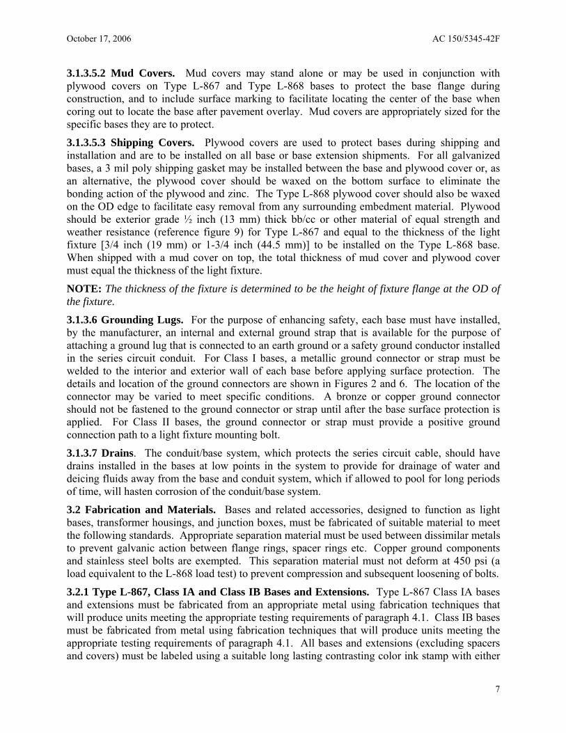
3.1.3.5.2 Mud Covers. Mud covers may stand alone or may be used in conjunction with plywood covers on Type L-867 and Type L-868 bases to protect the base flange during construction, and to include surface marking to facilitate locating the center of the base when coring out to locate the base after pavement overlay. Mud covers are appropriately sized for the specific bases they are to protect.
3.1.3.5.3 Shipping Covers. Plywood covers are used to protect bases during shipping and installation and are to be installed on all base or base extension shipments. For all galvanized bases, a 3 mil poly shipping gasket may be installed between the base and plywood cover or, as an alternative, the plywood cover should be waxed on the bottom surface to eliminate the bonding action of the plywood and zinc. The Type L-868 plywood cover should also be waxed on the OD edge to facilitate easy removal from any surrounding embedment material. Plywood should be exterior grade ½ inch (13 mm) thick bb/cc or other material of equal strength and weather resistance (reference figure 9) for Type L-867 and equal to the thickness of the light fixture [3/4 inch (19 mm) or 1-3/4 inch (44.5 mm)] to be installed on the Type L-868 base. When shipped with a mud cover on top, the total thickness of mud cover and plywood cover must equal the thickness of the light fixture.
NOTE: The thickness of the fixture is determined to be the height of fixture flange at the OD of the fixture.
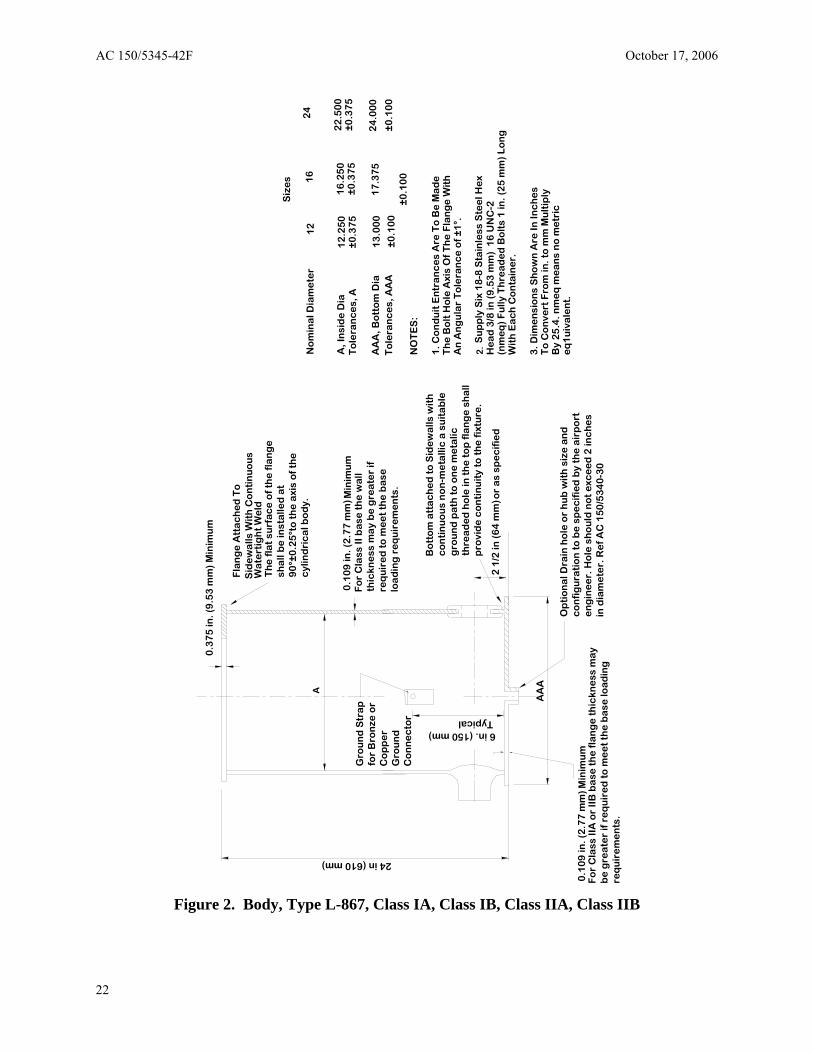
3.1.3.6 Grounding Lugs. For the purpose of enhancing safety, each base must have installed, by the manufacturer, an internal and external ground strap that is available for the purpose of attaching a ground lug that is connected to an earth ground or a safety ground conductor installed in the series circuit conduit. For Class I bases, a metallic ground connector or strap must be welded to the interior and exterior wall of each base before applying surface protection. The details and location of the ground connectors are shown in Figures 2 and 6. The location of the connector may be varied to meet specific conditions. A bronze or copper ground connector should not be fastened to the ground connector or strap until after the base surface protection is applied. For Class II bases, the ground connector or strap must provide a positive ground connection path to a light fixture mounting bolt.
3.1.3.7 Drains. The conduit/base system, which protects the series circuit cable, should have drains installed in the bases at low points in the system to provide for drainage of water and deicing fluids away from the base and conduit system, which if allowed to pool for long periods of time, will hasten corrosion of the conduit/base system.
3.2 Fabrication and Materials. Bases and related accessories, designed to function as light bases, transformer housings, and junction boxes, must be fabricated of suitable material to meet the following standards. Appropriate separation material must be used between dissimilar metals to prevent galvanic action between flange rings, spacer rings etc. Copper ground components and stainless steel bolts are exempted. This separation material must not deform at 450 psi (a load equivalent to the L-868 load test) to prevent compression and subsequent loosening of bolts.
3.2.1 Type L-867, Class IA and Class IB Bases and Extensions. Type L-867 Class IA bases and extensions must be fabricated from an appropriate metal using fabrication techniques that will produce units meeting the appropriate testing requirements of paragraph 4.1. Class IB bases must be fabricated from metal using fabrication techniques that will produce units meeting the appropriate testing requirements of paragraph 4.1. All bases and extensions (excluding spacers and covers) must be labeled using a suitable long lasting contrasting color ink stamp with either
7
AC 150/5345-42F October 17, 2006
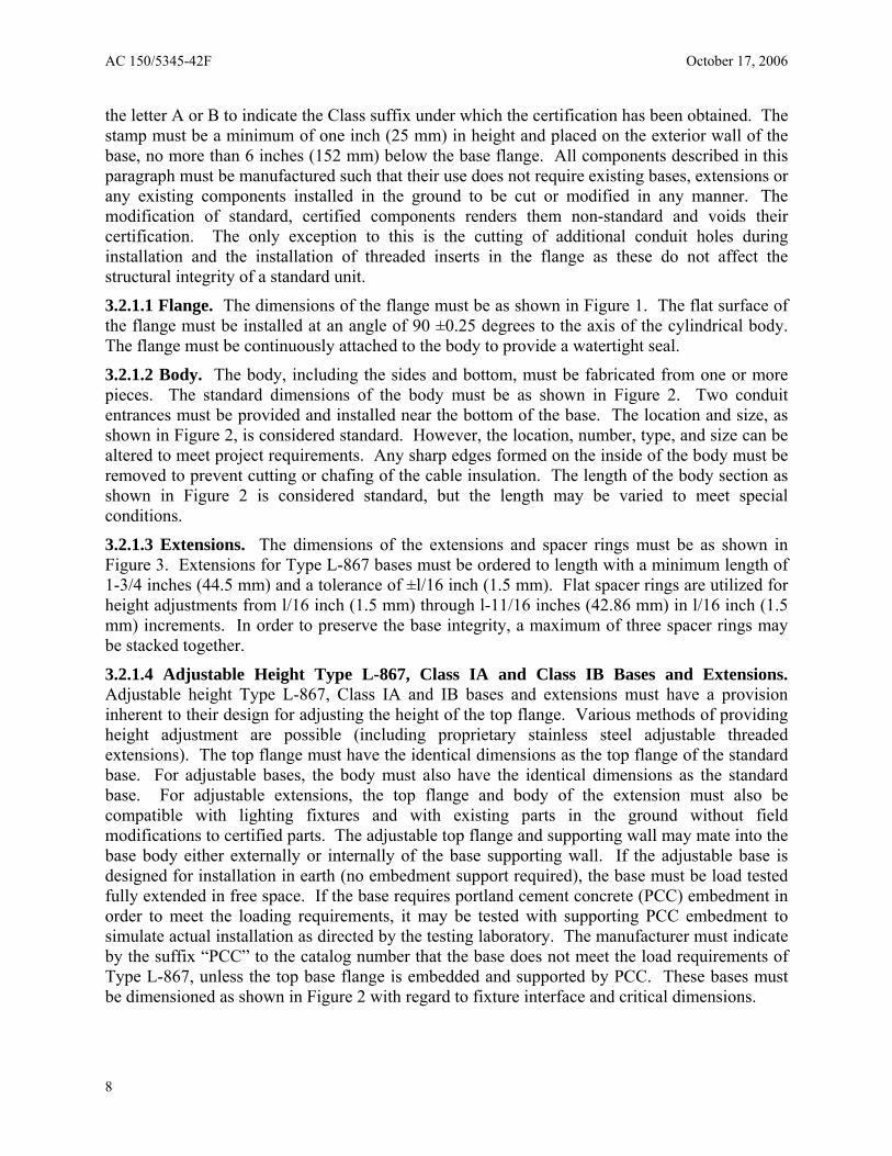
the letter A or B to indicate the Class suffix under which the certification has been obtained. The stamp must be a minimum of one inch (25 mm) in height and placed on the exterior wall of the base, no more than 6 inches (152 mm) below the base flange. All components described in this paragraph must be manufactured such that their use does not require existing bases, extensions or any existing components installed in the ground to be cut or modified in any manner. The modification of standard, certified components renders them non-standard and voids their certification. The only exception to this is the cutting of additional conduit holes during installation and the installation of threaded inserts in the flange as these do not affect the structural integrity of a standard unit.
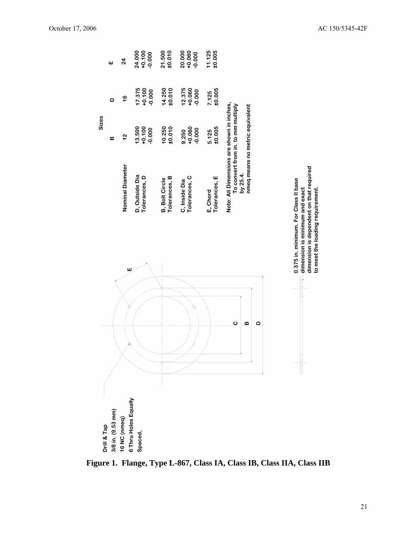
3.2.1.1 Flange. The dimensions of the flange must be as shown in Figure 1. The flat surface of the flange must be installed at an angle of 90 ±0.25 degrees to the axis of the cylindrical body. The flange must be continuously attached to the body to provide a watertight seal.
3.2.1.2 Body. The body, including the sides and bottom, must be fabricated from one or more pieces. The standard dimensions of the body must be as shown in Figure 2. Two conduit entrances must be provided and installed near the bottom of the base. The location and size, as shown in Figure 2, is considered standard. However, the location, number, type, and size can be altered to meet project requirements. Any sharp edges formed on the inside of the body must be removed to prevent cutting or chafing of the cable insulation. The length of the body section as shown in Figure 2 is considered standard, but the length may be varied to meet special conditions.
3.2.1.3 Extensions. The dimensions of the extensions and spacer rings must be as shown in Figure 3. Extensions for Type L-867 bases must be ordered to length with a minimum length of 1-3/4 inches (44.5 mm) and a tolerance of ±l/16 inch (1.5 mm). Flat spacer rings are utilized for height adjustments from l/16 inch (1.5 mm) through l-11/16 inches (42.86 mm) in l/16 inch (1.5 mm) increments. In order to preserve the base integrity, a maximum of three spacer rings may be stacked together.
3.2.1.4 Adjustable Height Type L-867, Class IA and Class IB Bases and Extensions. Adjustable height Type L-867, Class IA and IB bases and extensions must have a provision inherent to their design for adjusting the height of the top flange. Various methods of providing height adjustment are possible (including proprietary stainless steel adjustable threaded extensions). The top flange must have the identical dimensions as the top flange of the standard base. For adjustable bases, the body must also have the identical dimensions as the standard base. For adjustable extensions, the top flange and body of the extension must also be compatible with lighting fixtures and with existing parts in the ground without field modifications to certified parts. The adjustable top flange and supporting wall may mate into the base body either externally or internally of the base supporting wall. If the adjustable base is designed for installation in earth (no embedment support required), the base must be load tested fully extended in free space. If the base requires portland cement concrete (PCC) embedment in order to meet the loading requirements, it may be tested with supporting PCC embedment to simulate actual installation as directed by the testing laboratory. The manufacturer must indicate by the suffix “PCC” to the catalog number that the base does not meet the load requirements of Type L-867, unless the top base flange is embedded and supported by PCC. These bases must be dimensioned as shown in Figure 2 with regard to fixture interface and critical dimensions.
8
October 17, 2006 AC 150/5345-42F
3.2.1.5 Bolts. Bolts suitable for use in threaded holes, as shown in Figures 1 and 2, must be supplied with each base and extension assembly. The bolts must conform to the dimensions specified in the notes in Figures 1, 2, and 3 and must be fully threaded and fabricated from 18-8 stainless steel.
3.2.2 Type L-867, Class IIA and Class IIB Bases and Extensions. Type L-867 bases and extensions, Class IIA and IIB, must be fabricated from suitable materials and dimensioned so as to produce units meeting the appropriate testing requirements of paragraph 4.2. All bases and extensions (excluding spacers and covers) must be labeled using a suitable long lasting contrasting color ink stamp with either the letter A or B to indicate the Class suffix under which the certification has been obtained. The stamp must be a minimum of one inch (25 mm) in height and placed on the exterior wall of the base, no more than 6 inches (152 mm) below the base flange. All components described in this paragraph must be manufactured such that their use does not require existing cans, extensions, or any existing components installed in the ground to be cut or modified in any manner. The modification of standard certified components renders them non-standard and voids their certification. The only exception to this is the cutting of additional conduit holes during installation and the installation of threaded inserts in the flange as these do not affect the structural integrity of a standard unit.
3.2.2.1 Flange. The flange must be fabricated from suitable materials and must meet the same critical lighting fixture interface dimensions specified for Class I in Figure 1. Flange thickness and material should be sufficient to pass the load test specified in paragraph 4.1.1. The flange must be continuously attached to the body to provide a watertight seal.
3.2.2.2 Body. The body, sides, and bottom may be fabricated from one or more pieces. The sides and bottom must be fabricated from suitable materials sufficient to pass the load test described in paragraph 4.2.1. Two conduit entrances must be installed near the bottom of the base. The location and size, as shown in Figure 2, must be considered standard. However, the location, number, type, and size may be altered to meet project requirements. Any sharp edges formed on the inside of the body must be removed to prevent cutting or chafing of the cable insulation. The length of the body section as shown in Figure 2 must be considered standard, but the length may be varied to meet special conditions.
3.2.2.3 Extensions. The dimensions of the extensions and spacer rings must be as shown in Figure 3. Extensions must be fabricated of the same materials and dimensions specified in paragraphs 3.2.2.1 and 3.2.2.2. Extensions must be ordered to length with a minimum length of l-3/4 inches (44.5 mm) and a tolerance of ±l/16 inch (1.5 mm). Flat spacer rings are utilized for height adjustments from l/16 inch (1.5 mm) through l-11/16 inches (42.86 mm) in l/16 inch (1.5 mm) increments. In order to preserve the base integrity, a maximum of three spacer rings may be stacked together.
3.2.2.4 Adjustable Height Type L-867, Class IIA and Class IIB Bases and Extensions. Adjustable height Type L-867, Class IIA and IIB bases and extensions must have a provision inherent to their design for adjusting the height of the top flange. Various methods of providing height adjustment are possible (including proprietary stainless steel adjustable threaded extensions). The top flange must have the identical dimensions as the top flange of the standard base. The top flange must have the identical dimensions as the top flange of the standard base. For adjustable bases the body must also have the identical dimensions as the standard base. For adjustable extensions the top flange and body of the extension must also be compatible with
9
AC 150/5345-42F October 17, 2006
lighting fixtures and with existing parts in the ground without field modifications to certified parts. The adjustable top flange and supporting wall may mate into the base body either externally or internally of the base supporting wall. If the adjustable base is designed for installation in earth (no embedment support required) the base must be load tested fully extended in free space. If the base requires PCC embedment in order to meet the loading requirements, it may be tested with supporting PCC embedment to simulate actual installation as directed by the testing laboratory. The manufacturer must indicate by the suffix “PCC” to the catalog number that the base does not meet the load requirements of Type L-867 unless the top base flange is embedded and supported by PCC. These bases must be dimensioned as shown in Figure 2 with regard to fixture interface and critical dimensions.
3.2.2.5 Bolts. Bolts suitable for use in threaded holes as shown in Figures 1, 2, and 3 must be supplied with each base and extension assembly. The bolts must conform to the dimensions specified in the notes in Figures 1, 2, and 3, and must be fully threaded and fabricated from 18-8 stainless steel.
3.2.3 Type L-867 Accessories. Various accessories are necessary to facilitate construction involving Type L-867 bases or to make corrections or adjustments to Type L-867 bases. These accessories are detailed in Figure 4.
3.2.4 Type L-868, Class IA and Class IB Bases and Extensions. Type L-868, Class IA bases and extensions, must be fabricated from an appropriate metal* and constructed in such a manner as to meet the appropriate testing requirements given in paragraph 4.3. Class IB bases and extensions must be fabricated from an appropriate metal* and constructed in such a manner as to meet the appropriate testing requirements specified in paragraph 4.3.
*If a material other than ASTM A36 steel is used for a major load bearing structural component, the material must meet the mechanical property yield and tensile values of A36 steel. A material with yield and tensile stress values lower than the minimum specified values of A36 steel may be used if the manufacturer can demonstrate conformance to the requirements set forth in section 4 of this specification.
All bases and extensions (excluding spacers and covers) must be labeled using a suitable long lasting contrasting color ink stamp with either the letter A or B to indicate the Class suffix under which the certification has been obtained. The stamp must be a minimum 1 inch (25 mm) in height and placed on the exterior wall of the base, no more than 6 inches (152 mm) below the base flange.
All components described in this paragraph must be manufactured such that their use does not require existing cans, extensions or any existing components installed in the ground to be cut or modified in any manner. The modification of standard, certified components renders them nonstandard and voids their certification. The only exception to this is the cutting of additional conduit holes during installation and the installation of threaded inserts in the flange as these do not affect the structural integrity of a standard unit.
3.2.4.1 Flange. The dimensions of the flange must be as shown in Figure 5. The flat surface of the flange must be installed at an angle of 90 degrees, ±0.125 degree, to the axis of the cylindrical body of the base. The flange must be continuously attached to the body to provide a watertight seal. The flange faces, outside and inside diameter, must be finished in accordance with ASME B 46.1. Bolt hole size and placement must be as shown in Figure 5. Bolt hole may
10
October 17, 2006 AC 150/5345-42F
be integral to the flange or contained in metal insert located in the flange. A specified bolt installed in the flange bolt hole must be capable of accepting a bolt torque test as indicated in paragraph 4.3.4. As part of the base testing, any insert or remedial device used for correcting threads damaged while in service must be tested in the base flange as part of the base in which it is intended for service.
3.2.4.2 Body. The body section, sides and bottom, may be formed from one or more pieces. One piece body sections must have an anchor ring (mid-ring) attached to the body by a continuous weld applied to the upper side and lower side of the ring as shown in Figure 6. The length of the one piece body section shown in Figure 6 must be considered a standard, but the overall length may vary to meet specific conditions. Two 2-inch (51 mm) conduit entrances must be provided near the bottom of the body. The location, number, and size of conduit entrances shown in Figure 6 must be considered standard, but the size, location, and number of connections may be varied to meet specific conditions. Any sharp edges at the conduit entrances must be removed to prevent cutting or chafing of the cable insulation. When sectional bases are specified, the sections must be dimensioned as shown in Figure 7.
3.2.4.3 Extensions. Extensions must be fabricated from the appropriate metal for either Class IA or Class IB bases. The dimensions of extensions must be as shown in Figure 8. The minimum extension length must be 2 inches (51 mm) flat spacer rings must be used for height corrections of l/16 inch (1.6 mm) to l-15/16 inches (49 mm) in l/l6 inch (1.6 mm) increments. Flat spacer ring dimensions are shown in Figure 8. If specified, grooved spacer rings may be used for height corrections of l/4 inch (3.2 mm) to l-15/16 inches (49 mm) in l/16 inch (1.6 mm) increments.
3.2.4.4 Adjustable Height Type L-868, Class IA and Class IB Bases and Extensions. Adjustable height Type L-868, Class IA and IB bases and extensions must have a provision inherent to their design for adjusting the height of the top flange. Various methods of providing height adjustment are possible (including proprietary stainless steel adjustable threaded extensions). The top flange must have the identical dimensions as the top flange of the standard base. For adjustable bases the body must also have the identical dimensions as the standard base. For adjustable extensions the top flange and body of the extension must also be compatible with lighting fixtures and with existing parts in the ground without field modifications to certified parts. The adjustable top flange and supporting wall may mate into the base body either externally or internally of the base supporting wall.
3.2.4.5 Bolts. Bolts suitable for use in the threaded holes as shown in Figures 5, 6, and 7 must be supplied with each spacer ring. These bolts must be of sufficient length to provide a full thread connection with the base flange when the spacer ring is inserted between the light fixture and the base flange. If bases or extensions are ordered without spacer rings, bolts conforming to the dimensions specified in the notes in Figures 5, 6, and 7 must be supplied. All bolts must be fully threaded and fabricated from 18-8 stainless steel and supplied with stainless steel locking washers.
NOTE: Anti-seize material is recommended to be furnished and utilized by the installing contractor when installing bolts (Reference AC 150/5340-30). Anti-seize material is normally not supplied by the base manufacturer due to the various airport preferences for different brands of material.
11
AC 150/5345-42F October 17, 2006
3.2.5 Type L-868 Accessories. Various accessories are necessary to facilitate construction involving Type L-868 bases or make corrections or adjustments to Type L-868 bases. These accessories are detailed in Figure 9.
3.2.6 Grounding Lugs. Ground connectors or straps must be supplied with each base. A metallic ground connector or strap must be welded to the interior and exterior wall of each base before applying surface protection. The details and location of the ground connectors are shown in Figure 6. The location of the connector may be varied to meet specific conditions. A bronze or copper ground connector should not be fastened to the ground connector or strap until after the base surface protection is applied.
3.2.7 Drains. If specified, a drain should be provided in the bottom of the base prior to applying surface protection. When not otherwise specified, the drain should be 3/4 inch (19 mm) in diameter.
3.2.8 Protective Coating. After fabrication, burrs and sharp edges must be removed, and all ferrous metal parts must be treated for corrosion protection. Prior to tapping operations, all parts of Class I bases, extensions, and spacer rings in excess of l/4 inch (6.35 mm) in thickness must be hot-dip galvanized, as specified in ASTM A123/A123M-02 , and applied in accordance with ASTM A 385-03 . Flanges, covers, and rings must be wiped smooth to a flatness of ±0.010 inch (0.254 mm). Plates and rings l/4 inch (6.35 mm) or less in thickness, grooved extensions, and grooved spacer rings when made of ferrous metal must be plated with zinc in accordance with the requirements of ASTM B 633, Type II, Class I or hot dip galvanized in accordance with ASTM A123/A123M-02. Tapped holes for conduit must be protected with a polyurethane varnish or equivalent. A zinc dust primer meeting MIL-PRF-26915 must be permitted for touchup. The area covered by zinc dust primer must not exceed 10 percent of the total treated area. Any cast iron may be coated with a minimum of 2.0 mils of oxyplast powder in lieu of galvanizing. Class IA base extensions and spacer rings must utilize surface protection, as required, meeting the appropriate testing requirements stated in paragraph 4.4.
12
October 17, 2006 AC 150/5345-42F
SECTION 4. QUALITY ASSURANCE PROVISIONS
Equipment produced under this specification may be eligible for funding for installation on airports under Federal grant assistance programs for airports. In order to be eligible for installation under Federal grant assistance programs, manufacturers of the types of equipment specified herein are required to certify or furnish proof to the airport sponsor, or the sponsor’s representative, that the equipment is certified by an FAA-approved Third Party Certification Body to meet the following test specimen, and production provisions established in paragraphs 4.1, 4.2 and 4.3 Certification Testing. Certification testing is intended to assure that the materials and fabrication methods are adequate to provide acceptable in-service performance of bases. Certification testing is required for each type, class, and size of base produced. The third party certification body must make a permanent record (for up to seven years beyond the life of the certification) of the exact material and fabrication process used for the prototype submitted for certification. Any change in material or fabrication process requires the certification of the resultant product as a new product being submitted for certification. After testing and qualification are complete, the prototype accepted for qualification must serve as the dimensional and workmanship model for all subsequent production units.
4.1 Type L-867, Class IA and Class IB Certification Testing. Type L-867, Class IA and Class IB bases and extensions fabricated in accordance with the materials and dimensions specified herein must be capable of passing the following tests:
4.1.1 Type L-867, Class IA and Class IB Load Test. Sample bases and extensions must be subject to the load test described below. The base and cover assembly or assemblies including spacer rings, extensions, and multi-section bodies must be bolted together and placed on a flat steel plate mounted in a standard testing machine. The test section must be a unit in height deemed to be the maximum height to be furnished by the manufacturer with four 2 inch (51 mm) conduit entrances located in the body section, located at 90 degree increments, 2-l/2 inches (64 mm) from the bottom of the base. A load must be applied to the top part of the base through a block of rubber l-1/2 inches (38 mm) thick, with a diameter equal to the cover plate, and having a durometer hardness of 55 to 70. A load of 250 psi (1724 kPa) must be applied uniformly over the area of the rubber block at a rate not to exceed 10,000 pounds (4536 kg) per minute. The base or any of the components will be considered unsatisfactory if there is any permanent deformation or cracking of material or coating. The above test will be repeated three times. After each loading, bolts must be checked for loss of tension. The bolts must be torqued to the manufacturer’s recommended service torque after the first two loadings. The base and/or assembly will be considered unsatisfactory if there is any loss of torque in the bolts or permanent deformation of the flange or coating after the third loading. Load testing is to be performed on free standing units.
4.1.1.1 Type L-867, Class IA and Class IB Load Test, Adjustable Height Bases and Extensions. If the adjustable base or extension is designed for installation in earth (no embedment support required), the base or extension must be tested fully extended in free space and must be subject to the load test in paragraph 4.1.1. If the base or extension requires PCC embedment in order to meet the loading requirements, it may be tested to the requirements in paragraph 4.1.1 with supporting PCC embedment to simulate actual installation as directed by the testing laboratory.
13
AC 150/5345-42F October 17, 2006
4.1.2 Type L-867, Class IA and Class IB Weld Integrity Test. This test must be performed after each assembly has undergone the load test described in paragraph 4.1.1. An internal air or hydraulic pressure of 12 psi, ±2 psi, (83 kPa, ±14 kPa) must be maintained within the assembly using pressure fittings. The conduit entrances must include a sample of the conduit interfaces (hub, grommet etc.) that are offered by the manufacturer for interfacing to the conduit. The conduit entrances must include conduit stubs suitably plugged during the conducting of the test. A high foam soap or detergent solution of low surface tension must be brushed on welds, seams, and joints to detect leakage. Alternatively, the assembly may be submerged in a tank of water while pressurized to detect any air leakage. The assembly will be considered unsatisfactory if leakage is evident. The conduit entrances must be placed at least 24 inches (0.6 m) below the water surface. Any leakage of water into the assembly will be cause for rejection.
NOTE: This test is also to be performed on bases designed to be field height adjustable, but the extension itself does not have to be in place.
4.1.3 Type L-867, Class IA and Class IB Dimensional Tests. Specimens must be measured for conformance to the dimensions specified in Figures 1, 2, 3, and 4, as applicable. Should any new product be introduced that does not exactly conform to the fixed products shown, the applicable dimensions necessary to ensure compatibility with certified light fixtures and bases must be applied.
4.1.4 Type L-867, Class IA and Class IB Protective Coating Thickness Test. When utilized, the thickness of protective coatings must equal or exceed those specified herein. The weight of hot-dip galvanizing must be tested according to the method described in ASTM A 153. Zinc plating thickness must be tested by a method described in ASTM B 633.
4.1.5 Type L-867, Class IA and Class IB Visual Inspection. Each unit must be visually inspected for quality of workmanship and materials. The specified Class marking must be inspected for correctness. Particular attention must be given to smoothness and continuity of welds and seams, flatness and smoothness of the flange surface, complete and uniform application of the protective coating, freedom from excess zinc when applicable, and absence of burrs, sharp edges, cracks, voids, penetrations or any other imperfection that could potentially affect the structural integrity or performance of the product.
4.1.6 Type L-867, Class IB Potassium Acetate Test. Those bases and extensions certified to Type L-867 Class IB requirements must be subjected to testing to determine if they are resistant to corrosion caused by deicing fluids containing potassium acetate. The test consists of taking a test base and filling it half full with a potassium acetate deicing fluid composed of 50 percent potassium acetate and 50 percent water, by weight. The test base will have conduit connecting devices identical to that to be furnished with the base with conduit stubs plugged and the top of the base must be covered with an appropriate blank cover and gasket. The test base will remain for 21 days at an elevated temperature of 194°F (90ºC). After the test period the base and spacer ring must be inspected. There must be no evidence of corrosion or leakage.
4.2 Type L-867, Class IIA and Class IIB Certification Testing. Type L-867, Class IIA and Class IIB bases and extensions fabricated from materials to dimensions as specified herein must be capable of passing the following tests.
4.2.1 Type L-867, Class IIA and Class IIB Load Test. Sample bases and extensions must be subjected to the load test described in paragraph 4.1.1.
14
October 17, 2006 AC 150/5345-42F
4.2.2 Type L-867, Class IIA and Class IIB Weld Integrity Test. Sample bases and extensions must be subjected to the leakage test described in paragraph 4.1.2.
NOTE: This test is also to be performed on bases designed to be field height adjustable, but the extension itself does not have to be in place.
4.2.3 Type L-867, Class IIA and Class IIB Temperature Shock Test. Temperature shock test requirements apply only to Class II, non-metallic, Type L-867 bases. A temperature shock test must be conducted on a completed non-metallic base assembly. The test must be performed according to MIL-STD-810, Method No. 503.2, Paragraph II, Procedure I. The high test temperature must be conducted at +130ºF (+54ºC) and the low test temperature must be conducted at -65ºF (-54ºC). This test must be conducted on the assembly after the load test described in paragraph 4.1.1 has been concluded. Any cracking or joint separation of the materials making up the base assembly will be cause for rejection.
4.2.4 Type L-867, Class IIA and Class IIB Dimensional Tests. Specimens must be measured for conformance to the dimensions specified in Figures 1, 2, 3, and 4, as applicable. Mounting flange and base wall thicknesses must be measured and must be equal to or greater than those required to pass the load test and torque test described in paragraph 4.1.1. Should any new product be introduced that does not exactly conform to the fixed products shown, the applicable dimensions necessary to ensure compatibility with certified light fixtures and bases must be applied.
4.2.5 Type L-867, Class IIA and Class IIB Protective Coating Thickness Test. For components of the base or assembly requiring protective coatings, the thickness of protective coatings must be tested in accordance with paragraph 4.1.4.
4.2.6 Type L-867, Class IIA and Class IIB Visual Inspection. Bases must be visually inspected in accordance with paragraph 4.1.5.
4.2.7 Type L-867, Class IIB Potassium Acetate Test. Those bases and extensions certified to Type L-867 Class IIB requirements must be subjected to testing to determine if they are resistant to corrosion caused by deicing fluids containing potassium acetate. The test must be conducted in accordance with paragraph 4.1.6.
4.3 Type L-868, Class IA and Class IB Certification Testing. Type L-868, Class I bases and extensions fabricated in accordance with the materials and dimensions specified herein must be capable of passing the following tests.
4.3.1 Type L-868, Class IA and Class IB Load Test. Sample bases and extensions must be subject to the load test described in paragraph 4.1.1 with the following exception. A load of 450 psi (3,103 kPa) must be applied uniformly over the area of the rubber block at a rate not to exceed 10,000 pounds (4,536 kg) per minute. The test section must be a unit in height deemed to be the maximum height, to be furnished by the manufacturer. For 8 inch (203 mm) Type L-868, one inch (25 mm) conduit entrances must be used.
4.3.2 Type L-868, Class IA and Class IB Fatigue Test. If a material other than ASTM A36 steel is used for a major load-bearing structural component, the material must have a fatigue limit or endurance limit no less than 27 ksi (186 MPa). Specimens from the proposed material must be able to withstand a minimum of 5 × 10⁷ cycles at 27 ksi (186 MPa) by a standard R.R. Moore rotating beam fatigue test using polished specimens. No less than three tests must be conducted to validate the material’s fatigue properties.
15
AC 150/5345-42F October 17, 2006
4.3.3 Type L-868, Class IA and Class IB Impact Test. If a material other than ASTM A36 steel is used for a major load-bearing structural component, the material must have an impact toughness equal to or greater than 15 ft-lb (20 J) at 20°F (-7°C), per the Charpy V-notch test specified in ASTM E 23. No less than three tests must be conducted to validate the material’s impact properties.
4.3.4 Type L-868, Class IA and Class IB Flange Bolt Torque Test. Flanges must be tested by inserting 18-8 stainless steel fixture mounting bolts in all 6 bolt holes and torquing all bolts to failure. Any cracking or permanent deformation of the flange material will be cause for rejection. Any rotation or distortion of installed remedial devices or replaceable inserts will also be cause for rejection.
4.3.5 Type L-868, Class IA and Class IB Weld Integrity Test. Sample bases and extensions must be subjected to the leakage test described in paragraph 4.1.2.
NOTE: This test is also to be performed on bases designed to be field height adjustable, but the extension itself does not have to be in place.
4.3.6 Type L-868, Class IA and Class IB Dimensional Tests. Specimens must be measured for conformance to the dimensions specified in Figures 5-9, as applicable. Should any new product be introduced that does not exactly conform to the fixed products shown, the applicable dimensions necessary to ensure compatibility with certified light fixtures and bases must be applied.
4.3.7 Type L-868, Class IA and Class IB Protective Coating Thickness Test. For components of the base or assembly requiring protective coatings, the thickness of protective coatings must be tested in accordance with paragraph 4.1.4.
4.3.8 Type L-868, Class IA and Class IB Visual Inspection. Specimens must be subject to visual inspection as described in paragraph 4.1.5.
4.3.9 Type L-868, Class IB Potassium Acetate Test. Bases and Extensions must be subjected to testing to determine if they are resistant to corrosion caused by deicing fluids containing potassium acetate. The test must be conducted in accordance with paragraph 4.1.6.
4.3.10 Type L-868, Class IA and Class IB Torque Test for Adjustable Height Bases and Extensions. All L-868 bases and extensions that utilize a method of height adjustment that is inherent to their design that are designed for field adjustment must be subjected to a torque test. The test base must be held in the maximum adjustable height position utilizing the locking method that will be utilized in the actual installation. A torque of 100,000 in-lbs (11,000 Newton-meters (N-m)) must be applied perpendicular to the vertical axis of the base utilizing a steel cover plate. The maximum torque must be achieved within 60 seconds of the start of the test. The torque load must be applied three times. Upon completion of the third torque loading, a measurement must be taken to determine if the base top flange has been displaced in azimuth. An azimuth displacement of 0.25 degree or greater will be cause for rejection. All welds or seams must be examined for integrity and any failure will be cause for rejection.
NOTE: The locking method is defined as the method of locking that is inherent to the device itself. This does not include any type of embedment material that is used as a part of the installation - grout, concrete, asphalt, etc. In the past, torque testing in embedment material was permitted providing that production testing included random samples being torque tested in the field following installation to verify that the proper grout, etc., was applied in the proper manner
16
October 17, 2006 AC 150/5345-42F
as was done in the lab. History has shown that it is not possible to ensure that the appropriate production testing will be performed in the field for this verification to be made. Therefore, devices are to be tested free standing and the requirement to perform torque testing of random samples in the field is rescinded.
4.4 Production Testing 4.4.1 Lot Size. The lot size must be equal to the daily production rate.
4.4.2 Sample Size and Acceptance Criteria. Production testing must be based on the procedures given in ASQC Z1.4. Sample size and acceptance criteria must be based on Table 1 (Sample Size Code Letters), General Inspection Level I, Table II-A (Single Sampling Plans for Normal Inspection), and an Acceptable Quality Level (AQL) of 2.5. Note that normal inspection may be switched to reduced inspection provided the conditions set forth in ASQC Z1.4 are met.
4.4.3 Retesting. If the lot is rejected, the remainder of the lot may be tested and inspected on an individual basis. As an alternative to individual testing and inspection, the remainder of the lot may be tested using criteria in ASQC Z1.4 for multiple sampling. Table IVB, Multiple Sampling Plans for Tightened Inspection, using the appropriate sample size and an AQL of 2.5, must be used. Should the lot fail under the multiple sampling plan criteria, all units must be inspected and tested individually and repaired as necessary. Any samples that fail under any of the above criteria must be repaired prior to shipment.
4.4.4 Type L-867, Class IA and Class IB. 4.4.4.1 Dimensional Tests. Random samples from each lot must be subjected to dimensional tests as described in paragraph 4.1.3.
4.4.4.2 Visual Inspection. Random samples from each lot must be subjected to visual inspection as described in paragraph 4.1.5.
4.4.4.3 Weld Integrity Test. Random samples from each lot must be subjected to the leakage test described in paragraph 4.1.2, except that load testing of production samples is not required.
4.4.5 Type L-867, Class IIA and Class IIB. 4.4.5.1 Dimensional Tests. Random samples from each lot must be tested in accordance with paragraph 4.2.4.
4.4.5.2 Visual Inspection. Random samples from each lot must be visually inspected in accordance with paragraph 4.1.5.
4.4.5.3 Weld Integrity Test. Random samples from each lot must be subjected to the leakage test described in paragraph 4.1.2, except that load testing of production samples is not required.
4.4.6 Type L-868, Class IA and Class IB. 4.4.6.1 Dimensional Test. Random samples from each lot must be tested for conformance to the dimensional test described in paragraph 4.3.6.
4.4.6.2 Visual Inspection. Random samples from each lot must be inspected for conformance to the requirements in paragraph 4.3.8.
4.4.6.3 Weld Integrity Test. Random samples from each lot must be subjected to the leakage test described in paragraph 4.1.2, except that load testing of production samples is not required.
17

AC 150/5345-42F October 17, 2006
Intentionally left blank.
18
October 17, 2006 AC 150/5345-42F
SECTION 5. PREPARATION FOR DELIVERY.
5.1 Packing. Equipment must be carefully packaged for shipment and delivery to avoid damage and/or corrosion. Protective covers are to be included on all bases. (See paragraph 3.1.3.5.3)
5.2 Marking. Equipment must be marked for shipment with the consignee’s name and address, and other pertinent information as needed by the installer. Marking must include the following statement, “Installer: These products have been packed and shipped in accordance with FAA recommendations. Products are to be handled carefully so no damage to the structure or finish will occur during the installation process.”
19

AC 150/5345-42F October 17, 2006
Intentionally left blank.
20
October 17, 2006 AC 150/5345-42F
Figure 1. Flange, Type L-867, Class IA, Class IB, Class IIA, Class IIB
Siz
es
B
DE
No
min
al D
iam
ete
r 1
2
16
2
4
D, O
uts
ide
Dia
13
.50
01
7.3
75
24
.00
0
To
lera
nc
es,
D+
0.1
00
+0
.10
0+
0.1
00
-0
.00
0-0
.00
0-0
.00
0
B, B
olt
Cir
cle
10
.25
01
4.2
50
21
.50
0
To
lera
nc
es,
B±
0.0
10
±
0.0
10
±0
.01
0
C, I
nsi
de
Dia
9.2
50
12
.37
52
0.0
00
T
ole
ran
ce
s, C
+0
.06
0+
0.0
60
+0
.06
0
-0.0
00
-0.0
00
-0.0
00
E, C
ho
rd5
.12
57
.12
51
1.1
25
T
ole
ran
ce
s, E
±0
.00
5
±0
.00
5
±0
.00
5
No
te: A
ll D
ime
nsi
on
s a
re s
ho
wn
in in
ch
es,
To
co
nve
rt f
rom
in. t
o m
m m
ult
iply
by
25
.4.
nm
eq
me
an
s n
o m
etr
ic e
qu
iva
len
t
Dri
ll &
Ta
p
3/8
in. (
9.5
3 m
m)
16
NC
(n
me
q)
6 T
hru
Ho
les
Eq
ua
lly
Sp
ac
ed
,
E
C B D
0.3
75
in. m
inim
um
. Fo
r C
lass
II b
ase
dim
en
sio
n is
min
imu
m a
nd
exa
ct
dim
en
sio
n is
de
pe
nd
en
t o
n t
ha
t re
qu
ire
d
to m
ee
t th
e lo
ad
ing
re
qu
ire
me
nt.
21
AC 150/5345-42F October 17, 2006
Siz
es
No
min
al D
iam
ete
r1
2
16
2
4
A, I
nsi
de
Dia
1
2.2
50
16
.25
02
2.5
00
To
lera
nc
es,
A±
0.3
75
±
0.3
75
±0
.37
5
AA
A, B
ott
om
Dia
1
3.0
00
1
7.3
75
2
4.0
00
To
lera
nc
es,
AA
A
±0
.10
0
±0
.10
0
±0
.10
0
NO
TE
S:
1. C
on
du
it E
ntr
an
ce
s A
re T
o B
e M
ad
eT
he
Bo
lt H
ole
Axi
s O
f T
he
Fla
ng
e W
ith
An
An
gu
lar
To
lera
nc
e o
f ±
1°.
2.
Su
pp
ly S
ix 1
8-8
Sta
inle
ss S
tee
l He
xH
ea
d 3
/8 in
(9
.53
mm
) 1
6 U
NC
-2(n
me
q)
Fu
lly T
hre
ad
ed
Bo
lts
1 in
. (2
5 m
m)
Lo
ng
W
ith
Ea
ch
Co
nta
ine
r.
3. D
ime
nsi
on
s S
ho
wn
Are
In In
ch
es
To
Co
nve
rt F
rom
in. t
o m
m M
ult
iply
By
25
.4. n
me
q m
ea
ns
no
me
tric
eq
1u
iva
len
t.
0.3
75
in. (
9.5
3 m
m)
Min
imu
m
Fla
ng
e A
tta
ch
ed
To
S
ide
wa
lls W
ith
Co
nti
nu
ou
s
Th
e f
lat
surf
ac
e o
f th
e f
lan
ge
sh
all
be
inst
alle
d a
t9
0°±
0.2
5°t
o t
he
axi
s o
f th
e
0.1
09
in. (
2.7
7 m
m) M
inim
um
thic
kne
ss m
ay
be
gre
ate
r if
req
uir
ed
to
me
et
the
ba
se
Bo
tto
m a
tta
ch
ed
to
Sid
ew
alls
wit
hc
on
tin
uo
us
no
n-m
eta
llic
a s
uit
ab
leg
rou
nd
pa
th t
o o
ne
me
talic
thre
ad
ed
ho
le in
th
e t
op
fla
ng
e s
ha
llp
rovi
de
co
nti
nu
ity
to t
he
fix
ture
.
2 1
/2 in
(6
4 m
m) o
r a
s sp
ec
ifie
d
AA
A
Op
tio
na
l Dra
in h
ole
or
hu
b w
ith
siz
e a
nd
0.1
09
in. (
2.7
7 m
m) M
inim
um
c
on
fig
ura
tio
n t
o b
e s
pe
cif
ied
by
the
air
po
rt
Fo
r C
lass
IIA
or
IIB
ba
se t
he
fla
ng
e t
hic
kne
ss m
ay
en
gin
ee
r. H
ole
sh
ou
ld n
ot
exc
ee
d 2
inc
he
s
24 in (610 mm)
A
Wa
tert
igh
t W
eld
6 in . ( 150 mm ) Typi cal
Fo
r C
lass
II b
ase
th
e w
all
loa
din
g r
eq
uir
em
en
ts.
cyl
ind
ric
al b
od
y.
Gro
un
d S
tra
p
for
Bro
nze
or
Co
pp
er
Gro
un
d
Co
nn
ec
tor
be
gre
ate
r if
re
qu
ire
d t
o m
ee
t th
e b
ase
loa
din
gin
dia
me
ter.
Re
f A
C 1
50
/53
40
-30
req
uir
em
en
ts.
Figure 2. Body, Type L-867, Class IA, Class IB, Class IIA, Class IIB
22
D 16
17
.37
5
14
.25
0±0
.01
0
12
.37
5
+0
.06
0
-0
.00
0
7.1
25
±0.0
05
16
.25
0
±
0.3
75
E 24
24
21
.50
0
±0
.01
0
2
0.0
00
+
0.0
60
-0.0
00
1
1.1
25
22
.50
0
±0
.37
5
Siz
es
B
No
min
al D
iam
ete
r 1
2
D, O
uts
ide
Dia
Min
imu
m
13
.50
0
B, B
olt
Cir
cle
10
.25
0
To
lera
nc
es,
B
±
0.0
10
C, I
nsi
de
Dia
9.2
50
To
lera
nc
es,
C
+0
.06
0
-0.0
00
E, C
ho
rd
5.1
25
T
ole
ran
ce
s, E
±
0.0
05
A, A
ctu
al D
ia
12
.25
0
To
lera
nc
es,
A
±0
.37
5
Ext
en
sio
n
He
igh
t to
Ord
er
1-3
/4 in
ch
(4
4 m
m)
min
imu
mT
ole
ran
ce
±1
/16
in.
(±1
.5 m
m)
C B D
C B D
7/1
6 in
(11
.1 m
m)
6 T
hru
Ho
les
Eq
ua
lly S
pa
ce
d
E
E
Fla
ng
e T
hic
kne
ss 3
/8 in
. (9
.5 m
m)
for
Cla
ss I,
as
Re
qu
ire
d fo
r C
lass
II
Fla
ng
e T
hic
kne
ss 3
/8 in
. (9
.5 m
m)
for
Cla
ss I,
as
Re
qu
ire
d fo
r C
lass
II
A0
.10
9 in
(2
.77
mm
) m
in. C
lass
1
As
req
'd C
lass
II
NO
TE
S:
1. H
ole
s In
To
p A
nd
Bo
tto
m O
f E
xte
nsi
on
s S
ha
ll B
e
Alig
ne
d.
2. S
up
ply
6 S
tain
less
Ste
el 1
8-8
He
x H
ea
d 3
/8 in
.(9
.53
mm
) 1
6 U
NC
(n
me
q)
Bo
lts
Wit
h E
ac
h E
xte
nsi
on
S
uff
icie
ntl
y L
on
g T
o P
rovi
de
Min
imu
m 1
/2 in
. (1
3 m
m)
Th
rea
d E
ng
ag
em
en
t W
ith
Ba
se C
on
tain
er.
S
up
ply
6 S
tain
less
Ste
el 1
8-8
He
x H
ea
d 3
/8 in
. (9
.53
mm
)1
6 U
NC
(n
me
q)
Bo
lts
Wit
h E
ac
h E
xte
nsi
on
Su
ffic
ien
tly
L
on
g t
o P
rovi
de
Min
imu
m 1
/2 in
. (1
3 m
m)
Th
rea
d E
ng
ag
em
en
tW
ith
Ext
en
sio
n T
op
Fla
ng
e.
3. T
ab
ula
ted
Dim
en
sio
ns
Are
In In
ch
es,
To
Co
nve
rt
Fro
m in
. to
mm
Mu
ltip
ly B
y 2
5.4
. nm
eq
me
an
s n
o
me
tric
eq
uiv
ale
nt.
Sp
ac
er
Rin
g
1/1
6 in
(1
.5 m
m)
to 1 1
1/1
6 in
(4
3 m
m)
Dri
ll &
Ta
p3
/8 in
(9
.53
mm
)1
6 N
C (
nm
eq
)6
Th
ru H
ole
sE
qu
ally
Sp
ac
ed
.T
ap
aft
er
ap
plic
ati
on
of
pro
tec
tive
co
ati
ng
Dri
ll 7
/16
in(1
1.1
mm
) 6
Th
ruH
ole
s E
qu
ally
Sp
ac
ed
October 17, 2006 AC 150/5345-42F
Figure 3. Extensions, Type L-867, Class IA, Class IB, Class IIA, Class IIB
To
p a
nd
Bo
tto
m A
tta
ch
ed
to
S
ide
wa
lls W
ith
Co
ntu
no
us
Wa
tert
igh
t C
on
ne
cti
on
.
23
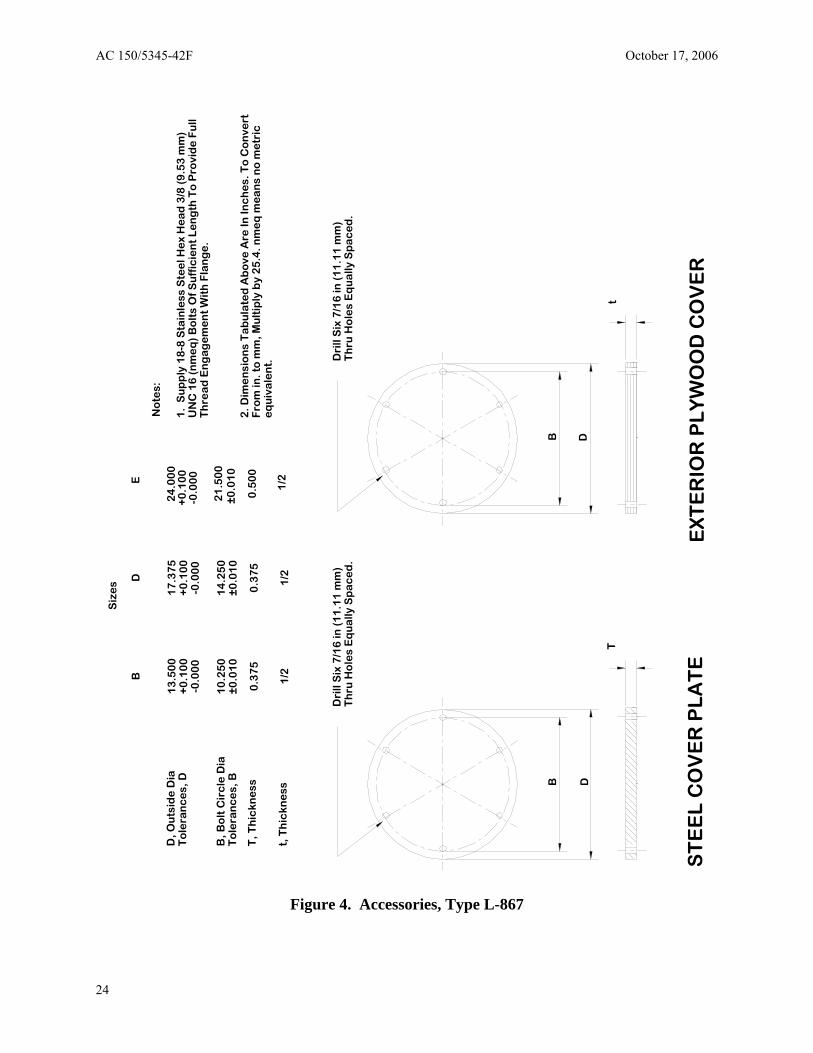
D, O
uts
ide
Dia
To
lera
nc
es,
D
B, B
olt
Cir
cle
Dia
To
lera
nc
es,
B
T, T
hic
kne
ss
t, T
hic
kne
ss
B
13
.50
0+
0.1
00
-0.0
00
10
.25
0±
0.0
10
0.3
75
1/2
Siz
es D
17
.37
5+
0.1
00
-0.0
00
14
.25
0±
0.0
10
0.3
75
1/2
E
24
.00
0+
0.1
00
-0.0
00
21
.50
0±
0.0
10
0.5
00
1/2
No
tes:
1.
Su
pp
ly 1
8-8
Sta
inle
ss S
tee
l He
x H
ea
d 3
/8 (
9.5
3 m
m)
UN
C 1
6 (
nm
eq
) B
olt
s O
f S
uff
icie
nt
Le
ng
th T
o P
rovi
de
Fu
ll T
hre
ad
En
ga
ge
me
nt
Wit
h F
lan
ge
.
2. D
ime
nsi
on
s T
ab
ula
ted
Ab
ove
Are
In In
ch
es.
To
Co
nve
rt
Fro
m in
. to
mm
, Mu
ltip
ly b
y 2
5.4
. nm
eq
me
an
s n
o m
etr
ice
qu
iva
len
t. Dri
ll S
ix 7
/16
in (
11
.11
mm
)T
hru
Ho
les
Eq
ua
lly S
pa
ce
d.
t
AC 150/5345-42F October 17, 2006
Figure 4. Accessories, Type L-867
D
Dri
ll S
ix 7
/16
in (
11
.11
mm
)T
hru
Ho
les
Eq
ua
lly S
pa
ce
d.
B D
T
B
ST
EE
L C
OV
ER
PL
AT
E
EX
TE
RIO
R P
LY
WO
OD
CO
VE
R
24
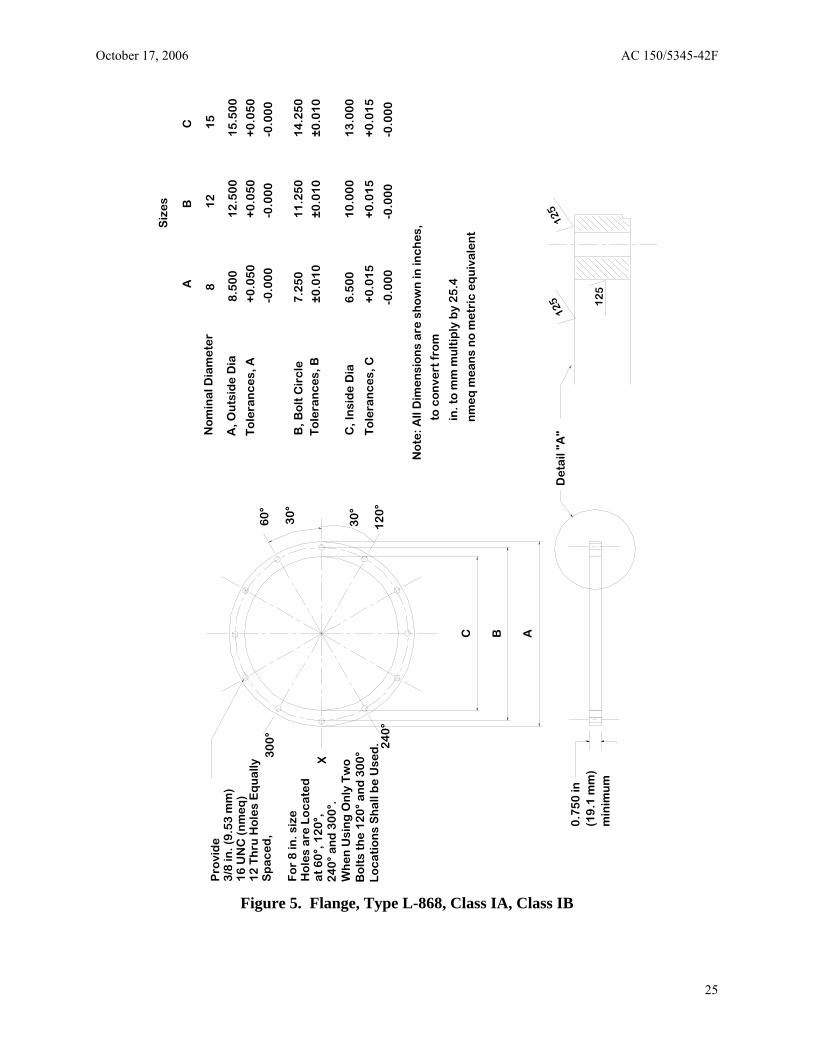
Siz
es
AB 1
2
Pro
vid
e
3/8
in. (
9.5
3 m
m)
16
UN
C (
nm
eq
)1
2 T
hru
Ho
les
Eq
ua
lly
Sp
ac
ed
,
Fo
r 8
in. s
ize
H
ole
s a
re L
oc
ate
d
at
60
°, 1
20
°,
24
0°
an
d 3
00
°.
Wh
en
Usi
ng
On
ly T
wo
B
olt
s th
e 1
20
° a
nd
30
0°
Lo
ca
tio
ns
Sh
all
be
Use
d.
0.7
50
in(1
9.1
mm
)m
inim
um
C B A
No
min
al D
iam
ete
r 8
A, O
uts
ide
Dia
To
lera
nc
es,
A
8.5
00
1
2.5
00
+0
.05
0
+0
.05
0
-0.0
00
-0.0
00
B, B
olt
Cir
cle
7
.25
0
11
.25
0
±0
.01
0±
0.0
10
C, I
nsi
de
Dia
6
.50
0
10
.00
0
To
lera
nc
es,
C
+0
.01
5
+0
.01
5
-0.0
00
-0
.00
0
No
te: A
ll D
ime
nsi
on
s a
re s
ho
wn
in in
ch
es,
to
co
nve
rt f
rom
in. t
o m
m m
ult
iply
by
25
.4
nm
eq
me
an
s n
o m
etr
ic e
qu
iva
len
t
De
tail
"A"
30
°
X
24
0°
60
°
30
°
12
0°
30
0°
To
lera
nc
es,
B
C 15
15
.50
0
+0
.05
0
-0.0
00
14
.25
0
±0
.01
0
13
.00
0
+0
.01
5
-0.0
00
October 17, 2006 AC 150/5345-42F
Figure 5. Flange, Type L-868, Class IA, Class IB
25
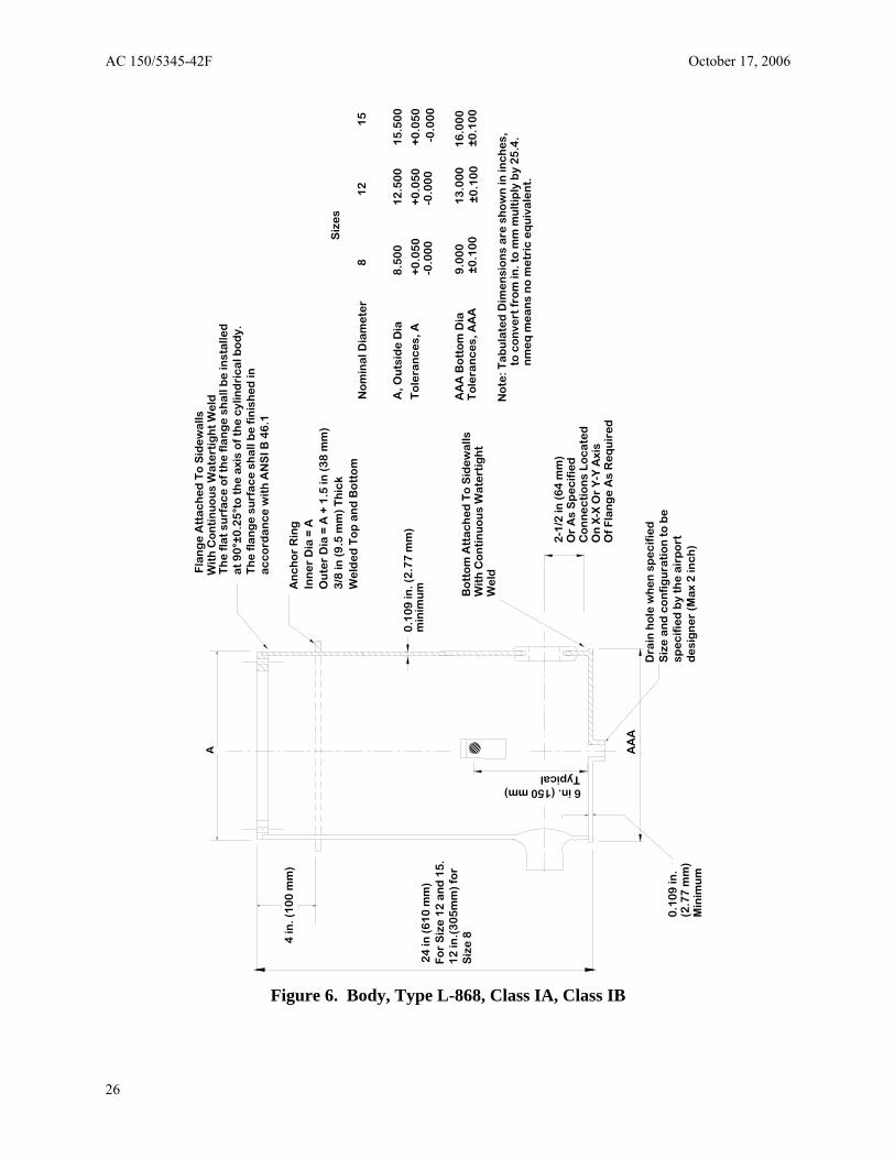
AC 150/5345-42F October 17, 2006
Fla
ng
e A
tta
ch
ed
To
Sid
ew
alls
A
Wit
h C
on
tin
uo
us
Wa
tert
igh
t W
eld
Th
e f
lat
surf
ac
e o
f th
e f
lan
ge
sh
all
be
inst
alle
d
at
90
°±0
.25
°to
th
e a
xis
of
the
cyl
ind
ric
al b
od
y.T
he
fla
ng
e s
urf
ac
e s
ha
ll b
e f
inis
he
d in
ac
co
rda
nc
e w
ith
AN
SI B
46
.1
An
ch
or
Rin
gIn
ne
r D
ia =
AO
ute
r D
ia =
A +
1.5
in (
38
mm
)3
/8 in
(9
.5 m
m)
Th
ick
Siz
es
We
lde
d T
op
an
d B
ott
om
N
om
ina
l Dia
me
ter
8 1
2
A, O
uts
ide
Dia
8
.50
0
12
.50
0
15
.50
0
0.1
09
in. (
2.7
7 m
m)
To
lera
nc
es,
A
+0
.05
0+
0.0
50
+0
.05
0-0
.00
0
-0.0
00
-0
.00
0
AA
A B
ott
om
Dia
9
.00
0
13
.00
0
16
.00
0
Bo
tto
m A
tta
ch
ed
To
Sid
ew
alls
To
lera
nc
es,
AA
A
±0
.10
0
±0
.10
0W
ith
Co
nti
nu
ou
s W
ate
rtig
ht
±0
.10
0
No
te: T
ab
ula
ted
Dim
en
sio
ns
are
sh
ow
n in
inc
he
s,to
co
nve
rt f
rom
in. t
o m
m m
ult
iply
by
25
.4.
nm
eq
me
an
s n
o m
etr
ic e
qu
iva
len
t.
2-1
/2 in
(6
4 m
m)
Or
As
Sp
ec
ifie
dC
on
ne
cti
on
s L
oc
ate
dO
n X
-X O
r Y
-Y A
xis
Of
Fla
ng
e A
s R
eq
uir
ed
0.1
09
in.
spe
cif
ied
by
the
air
po
rt(2
.77
mm
)d
esi
gn
er
(Ma
x 2
inc
h)
Min
imu
m
24
in (
61
0 m
m)
min
imu
m
4 in
. (1
00
mm
)
AA
A
We
ld
6 in. (150 mm) Typical
Fo
r S
ize
12
an
d 1
5.
12
in.(
30
5m
m)
for
Siz
e 8
Dra
in h
ole
wh
en
sp
ec
ifie
dS
ize
an
d c
on
fig
ura
tio
n t
o b
e
1
5
Figure 6. Body, Type L-868, Class IA, Class IB
26
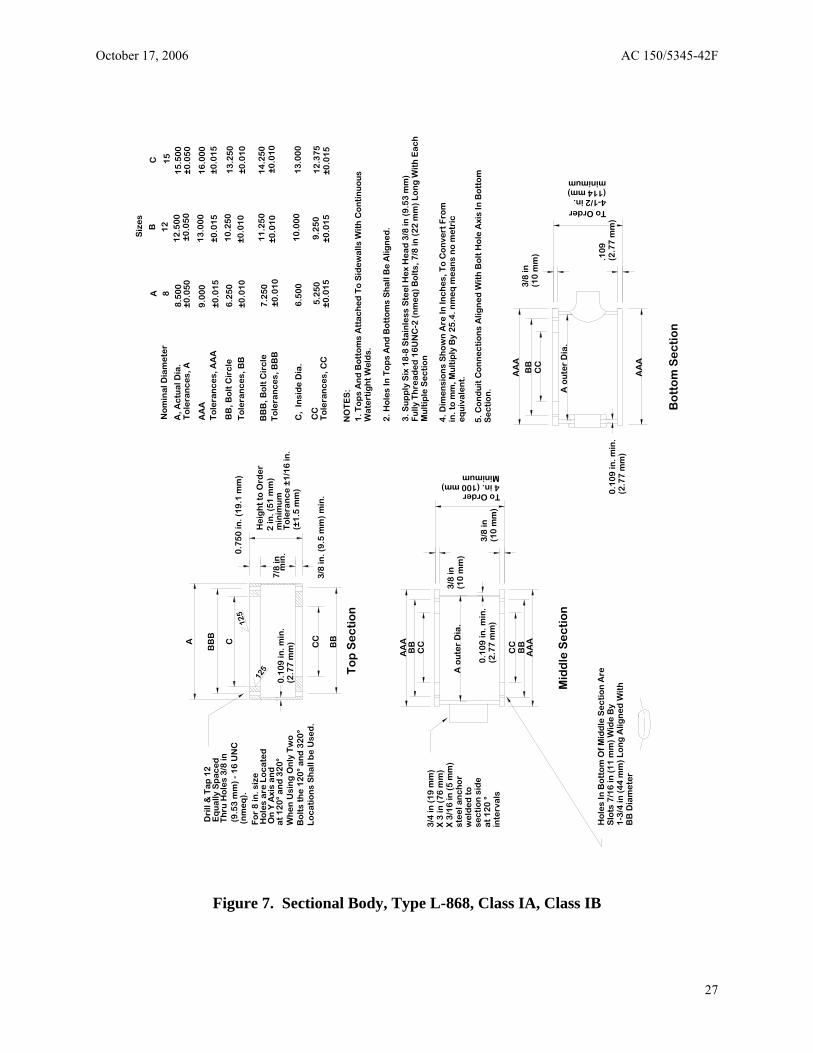
min
imu
mT
ole
ran
ce
±1
/16
in.
4. D
ime
nsi
on
s S
ho
wn
Are
In In
ch
es,
To
Co
nve
rt F
rom
in. t
o m
m, M
ult
iply
By
25
.4. n
me
q m
ea
ns
no
me
tric
eq
uiv
ale
nt.
5. C
on
du
it C
on
ne
cti
on
s A
lign
ed
Wit
h B
olt
Ho
le A
xis
In B
ott
om
Se
cti
on
.
AA
A3
/8 in
B
B
(10
mm
) C
C
A o
ute
r D
ia.
To Order 4-1/2 in. (114 mm) minimum
He
igh
t to
Ord
er
0.7
50
in. (
19
.1 m
m)
0.1
09
in. m
in.
(2.7
7 m
m)
No
min
al D
iam
ete
r A
B
C 1
51
28
Siz
es
To O r der
3/8
in(1
0 m
m)
3/8
in(1
0 m
m)
(2.7
7 m
m)
0.1
09
in. m
in.
0.1
09
in. m
in.
(2.7
7 m
m)
(2.7
7 m
m)
.10
9
Bo
tto
m S
ec
tio
n
Mid
dle
Se
cti
on
To
p S
ec
tio
n
CC
CC
BB
AA
A
CC
BB
AA
A
AA
A
BB
A, A
ctu
al D
ia.
To
lera
nc
es,
A
8.5
00
1
2.5
00
1
5.5
00
±0
.05
0
±0.0
50
±
0.0
50
AA
AT
ole
ran
ce
s, A
AA
9
.00
0
13
.00
0
16
.00
0
±0.0
15
±0
.01
5
±0.0
15
BB
, Bo
lt C
irc
le
To
lera
nc
es,
BB
6
.25
0
10
.25
0
13
.25
0
±0.0
10
±
0.0
10
±0
.01
0
A o
ute
r D
ia.
3/4
in (
19
mm
)X
3 in
(7
6 m
m)
X 3
/16
in (
5 m
m)
ste
el a
nc
ho
rw
eld
ed
to
sec
tio
n s
ide
at
12
0 °
inte
rva
ls
2 in
. (5
1 m
m)
BB
B
4 in. (100 mm) Minimum
Ho
les
In B
ott
om
Of
Mid
dle
Se
cti
on
Are
Slo
ts 7
/16
in (
11
mm
) W
ide
By
1-3
/4 in
(4
4 m
m)
Lo
ng
Alig
ne
d W
ith
BB
Dia
me
ter
CA
125
125
Dri
ll &
Ta
p 1
2
Th
ru H
ole
s 3
/8 in
(9.5
3 m
m)
- 1
6 U
NC
(nm
eq
).
Eq
ua
lly S
pa
ce
d
Fo
r 8
in. s
ize
Ho
les
are
Lo
ca
ted
On
Y A
xis
an
d
at
12
0°
an
d 3
20
°W
he
n U
sin
g O
nly
Tw
oB
olt
s th
e 1
20
° a
nd
32
0°
Lo
ca
tio
ns
Sh
all
be
Use
d.
7/8
inm
in.
BB
B, B
olt
Cir
cle
To
lera
nc
es,
BB
B
7.2
50
±0.0
10
11
.25
0±0
.01
0
14
.25
0±0
.01
0
(±1
.5 m
m)
3/8
in. (
9.5
mm
) m
in.
C,
Insi
de
Dia
. 6
.50
0
10
.00
0
13
.00
0
CC
5.2
50
9
.25
0
12
.37
5
To
lera
nc
es,
CC
±
0.0
15
±
0.0
15
±0
.01
5
NO
TE
S:
1. T
op
s A
nd
Bo
tto
ms
Att
ac
he
d T
o S
ide
wa
lls W
ith
Co
nti
nu
ou
s W
ate
rtig
ht
We
lds.
2. H
ole
s In
To
ps
An
d B
ott
om
s S
ha
ll B
e A
lign
ed
.
3. S
up
ply
Six
18
-8 S
tain
less
Ste
el H
ex
He
ad
3/8
in (
9.5
3 m
m)
Fu
lly T
hre
ad
ed
16
UN
C-2
(n
me
q)
Bo
lts,
7/8
in (
22
mm
) L
on
g W
ith
Ea
ch
Mu
ltip
le S
ec
tio
n
October 17, 2006 AC 150/5345-42F
Figure 7. Sectional Body, Type L-868, Class IA, Class IB
27
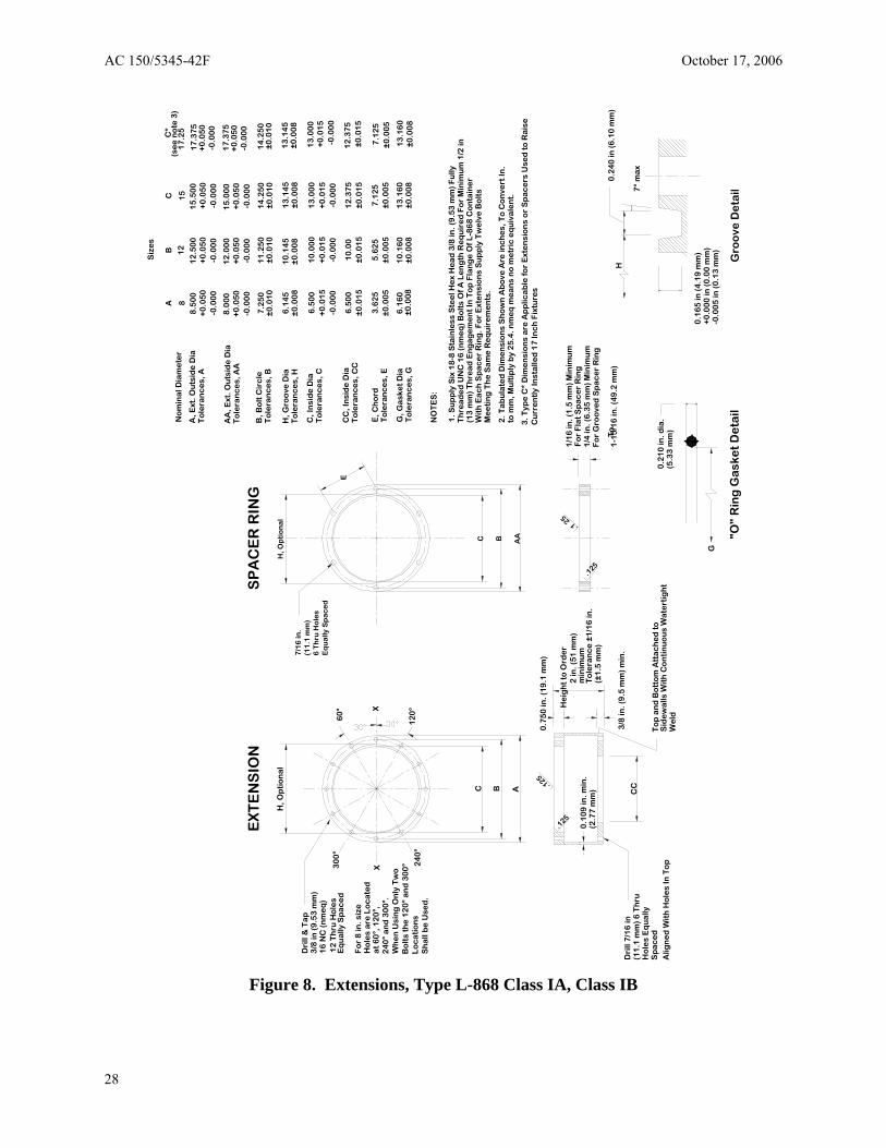
EX
TE
NS
ION
S
PA
CE
R R
ING
H, O
pti
on
al
H, O
pti
on
al
7/1
6 in
.D
rill
& T
ap
(11
.1 m
m)
3/8
in (
9.5
3 m
m)
6 T
hru
Ho
les
16
NC
(n
me
q)
Eq
ua
lly S
pa
ce
d
30
0°
Lo
ca
tio
ns
Sh
all
be
Use
d.
Ho
les
are
Lo
ca
ted
Eq
ua
lly S
pa
ce
d
C B A
60
°
X 24
0°
12
Th
ru H
ole
s
G, G
ask
et
Dia
To
lera
nc
es,
G
6.1
60
1
0.1
60
±0
.00
8
13
.16
0±
0.0
08
±0
.00
8
12
0°
7.1
25
±0
.00
5
13
.16
0±
0.0
08
24
0°
an
d 3
00
°.W
he
n U
sin
g O
nly
Tw
oB
olt
s th
e 1
20
° a
nd
30
0°
To
lera
nc
e ±
1/1
6 in
.
C B AA
E
.125
.125
E, C
ho
rdT
ole
ran
ce
s, E
3
.62
5
5.6
25
7
.12
5±
0.0
05
±0
.00
5±
0.0
05
X
Siz
es
AB
CC
*(s
ee
no
te 3
) N
om
ina
l Dia
me
ter
8
12
15
17
.25
A
, Ext
. Ou
tsid
e D
ia8
.50
0
12
.50
0
15
.50
0
17
.37
5T
ole
ran
ce
s, A
+0
.05
0+
0.0
50
+0
.05
0+
0.0
50
-0.0
00
-0
.00
0
-0.0
00
-0.0
00
AA
, Ext
. Ou
tsid
e D
ia8
.00
01
2.0
00
15
.00
01
7.3
75
To
lera
nc
es,
AA
+
0.0
50
+0
.05
0+
0.0
50
+0
.05
0
-0.0
00
-0
.00
0
-0.0
00
-0
.00
0
B, B
olt
Cir
cle
7.2
50
11
.25
01
4.2
50
14
.25
0T
ole
ran
ce
s, B
±0
.01
0
±0
.01
0
±0
.01
0±
0.0
10
H, G
roo
ve D
ia6
.14
51
0.1
45
1
3.1
45
13
.14
5T
ole
ran
ce
s, H
±
0.0
08
±
0.0
08
±
0.0
08
±
0.0
08
C, I
nsi
de
Dia
6.5
00
10
.00
01
3.0
00
13
.00
0T
ole
ran
ce
s, C
+0
.01
5
+0
.01
5
+0
.01
5+
0.0
15
-0.0
00
-0.0
00
-0.0
00
-0.0
00
CC
, In
sid
e D
ia6
.50
0
10
.00
1
2.3
75
12
.37
5T
ole
ran
ce
s, C
C
Fo
r 8
in. s
ize
±
0.0
15
±
0.0
15
±0
.01
5±
0.0
15
at
60
°, 1
20
°,
NO
TE
S:
1. S
up
ply
Six
18
-8 S
tain
less
Ste
el H
ex
He
ad
3/8
in. (
9.5
3 m
m)
Fu
lly
Th
rea
de
d U
NC
16
(n
me
q)
Bo
lts
Of
A L
en
gth
Re
qu
ire
d F
or
Min
imu
m 1
/2 in
(1
3 m
m)
Th
rea
d E
ng
ag
em
en
t In
To
p F
lan
ge
Of
L-8
68
Co
nta
ine
rW
ith
Ea
ch
Sp
ac
er
Rin
g. F
or
Ext
en
sio
ns
Su
pp
ly T
we
lve
Bo
lts
Me
eti
ng
Th
e S
am
e R
eq
uir
em
en
ts.
2. T
ab
ula
ted
Dim
en
sio
ns
Sh
ow
n A
bo
ve A
re in
ch
es,
To
Co
nve
rt In
.to
mm
, Mu
ltip
ly b
y 2
5.4
. nm
eq
me
an
s n
o m
etr
ic e
qu
iva
len
t.
3. T
ype
C*
Dim
en
sio
ns
are
Ap
plic
ab
le f
or
Ext
en
sio
ns
or
Sp
ac
ers
Use
d t
o R
ais
e
Cu
rre
ntl
y In
sta
lled
17
Inc
h F
ixtu
res
2 in
. (5
1 m
m)
1/1
6 in
. (1
.5 m
m)
Min
imu
m
min
imu
m0
.10
9 in
. min
.(2
.77
mm
)
(5.3
3 m
m)
0.2
10
in. d
ia.
He
igh
t to
Ord
er
Dri
ll 7
/16
in(1
1.1
mm
) 6
Th
ruH
ole
s E
qu
ally
Sp
ac
ed
T
op
an
d B
ott
om
Att
ac
he
d t
o
CC
0.7
50
in. (
19
.1 m
m)
3/8
in. (
9.5
mm
) m
in.
.125
.125
Sid
ew
alls
Wit
h C
on
tin
uo
us
Wa
tert
igh
t W
eld
A
lign
ed
Wit
h H
ole
s In
To
p
Fo
r F
lat
Sp
ac
er
Rin
g1
/4 in
. (6
.35
mm
) M
inim
um
(±1
.5 m
m)
Fo
r G
roo
ved
Sp
ac
er
Rin
g
"O"
Rin
g G
ask
et
De
tail
G
To
1-1
5/1
6 in
. (4
9.2
mm
)
Gro
ove
De
tail
-0.0
05
in (
0.1
3 m
m)
+0
.00
0 in
(0
.00
mm
) 0
.16
5 in
(4
.19
mm
)
H
0.2
40
in (
6.1
0 m
m)
7°
ma
x
AC 150/5345-42F October 17, 2006
Figure 8. Extensions, Type L-868 Class IA, Class IB
28
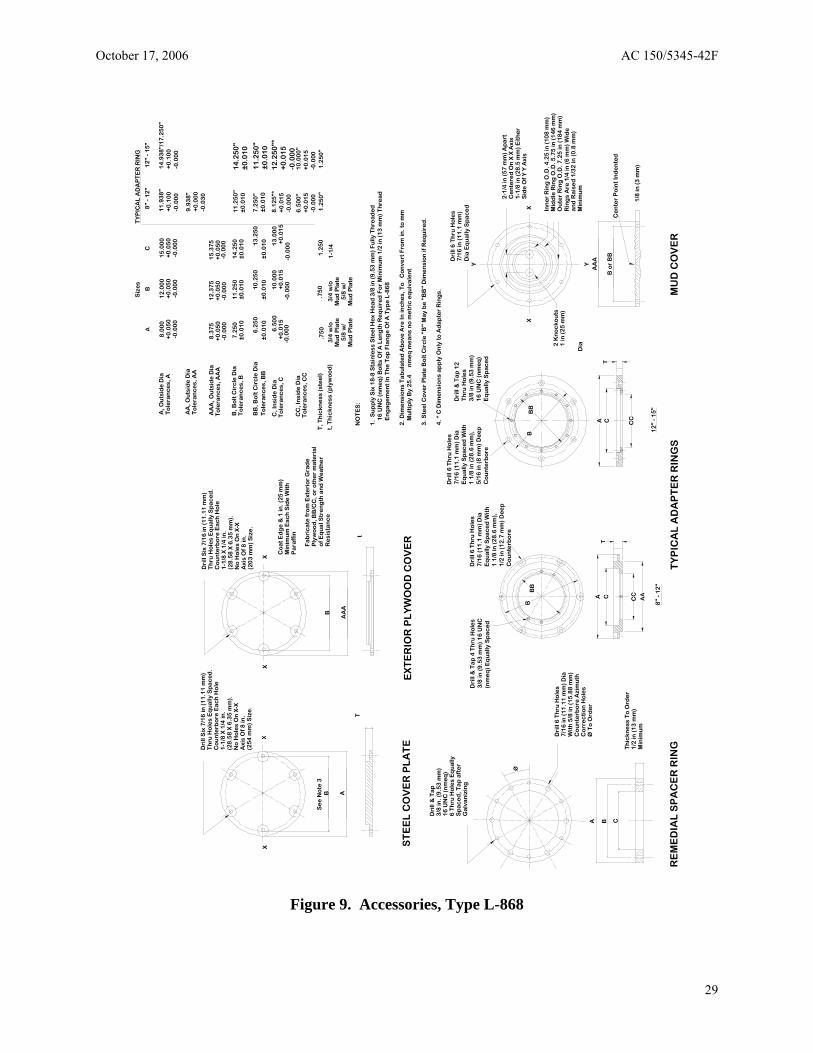
Siz
es
TY
PIC
AL
AD
AP
TE
R R
ING
8"
- 1
2"
12
" -
15
" A
BC
11
.93
8"
14
.93
8"/
17
.25
0"
To
lera
nc
es,
A+
0.0
50
+0
.05
0+
0.0
50
A, O
uts
ide
Dia
8.0
00
12
.00
01
5.0
00
+0
.10
0+
0.1
00
-0.0
00
-0
.00
0
-0.0
00
-0
.00
0
-0.0
00
AA
, Ou
tsid
e D
ia9
.93
8"
To
lera
nc
es,
AA
+0
.00
0D
rill
Six
7/1
6 in
(1
1.1
1 m
m)
Dri
ll S
ix 7
/16
in (
11
.11
mm
) -0
.03
0
Th
ru H
ole
s E
qu
ally
Sp
ac
ed
.T
hru
Ho
les
Eq
ua
lly S
pa
ce
d.
AA
A, O
uts
ide
Dia
8
.37
51
2.3
75
15
.37
5C
ou
nte
rbo
re E
ac
h H
ole
C
ou
nte
rbo
re E
ac
h H
ole
T
ole
ran
ce
s, A
AA
+
0.0
50
+
0.0
50
+
0.0
50
1-1
/8 X
1/4
in.
1-1
/8 X
1/4
in.
-0.0
00
-0
.00
0
-0.0
00
(2
8.5
8 X
6.3
5 m
m).
(2
8.5
8 X
6.3
5 m
m).
N
o H
ole
s O
n X
-X
No
Ho
les
On
X-X
B
, Bo
lt C
irc
le D
ia7
.25
01
1.2
50
14
.25
01
1.2
50
"1
4.2
50
"A
xis
Of
8 in
.A
xis
Of
8 in
. T
ole
ran
ce
s, B
±0
.01
0
±0
.01
0
±0
.01
0
±0
.01
0±
0.0
10
(25
4 m
m)
Siz
e.
(20
3 m
m)
Siz
e.
BB
, Bo
lt C
irc
le D
ia
6
.25
0
10
.25
0
13
.25
07
.25
0"
11
.25
0"
X
±0
.01
0
±0
.01
0
XX
X
T
ole
ran
ce
s, B
B
±0
.01
0±
0.0
10
±0
.01
0
C, I
nsi
de
Dia
6
.50
0
1
0.0
00
1
3.0
00
8
.12
5"*
12
.25
0"*
Co
at
Ed
ge
& 1
in. (
25
mm
)T
ole
ran
ce
s, C
+
0.0
15
+0
.01
5
+
0.0
15
+
0.0
15
+0
.01
5M
inim
um
Ea
ch
Sid
e W
ith
-0.0
00
-0
.00
0
-0.0
00
-0
.00
0-0
.00
0P
ara
ffin
C
C, I
nsi
de
Dia
6
.50
0"
10
.00
0"
Fa
bri
ca
te f
rom
Ext
eri
or
Gra
de
To
lera
nc
es,
CC
+
0.0
15
+0
.01
5P
lyw
oo
d, B
B/C
C, o
r o
the
r m
ate
ria
l-0
.00
0-0
.00
0
Se
e N
ote
3
of
Eq
ua
l Str
en
gth
an
d W
ea
the
rT
, Th
ickn
ess
(st
ee
l)
.75
0
.75
0
1.2
50
1
.25
0"
1.2
50
" B
B
Re
sist
an
ce
t,
Th
ickn
ess
(p
lyw
oo
d)
3/4
w/o
3/4
w/o
1
-1/4
M
ud
Pla
teM
ud
Pla
te
A
AA
A
5/8
w/
5/8
w/
Mu
d P
late
M
ud
Pla
te
T
t N
OT
ES
:
1.
Su
pp
ly S
ix 1
8-8
Sta
inle
ss S
tee
l He
x H
ea
d 3
/8 in
(9
.53
mm
) F
ully
Th
rea
de
d
1
6 U
NC
(n
me
q)
Bo
lts
Of
A L
en
gth
Re
qu
ire
d F
or
Min
imu
m 1
/2 in
(1
3 m
m)
Th
rea
d
En
ga
ge
me
nt
In T
he
To
p F
lan
ge
Of
A T
ype
L-8
68
2. D
ime
nsi
on
s T
ab
ula
ted
Ab
ove
Are
In in
ch
es,
To
C
on
vert
Fro
m in
. to
mm
S
TE
EL
CO
VE
R P
LA
TE
E
XT
ER
IOR
PL
YW
OO
D C
OV
ER
Mu
ltip
ly B
y 2
5.4
n
me
q m
ea
ns
no
me
tric
eq
uiv
ale
nt
3. S
tee
l Co
ver
Pla
te B
olt
Cir
cle
"B
" M
ay
be
"B
B"
Dim
en
sio
n if
Re
qu
ire
d.
Dri
ll &
Ta
p
3/8
in. (
9.5
3 m
m)
4. *
C D
ime
nsi
on
s a
pp
ly O
nly
to
Ad
ap
ter
Rin
gs.
1
6 U
NC
(n
me
q)
6 T
hru
Ho
les
Eq
ua
lly
Dri
ll 6
Th
ru H
ole
sD
rill
6 T
hru
Ho
les
Sp
ac
ed
, Ta
p a
fte
r7
/16
(1
1.1
mm
) D
iaD
rill
& T
ap
12
7/1
6 in
(1
1.1
mm
)G
alv
an
izin
g
Eq
ua
lly S
pa
ce
d W
ith
Th
ru H
ole
sD
ia E
qu
ally
Sp
ac
ed
D
rill
& T
ap
4 T
hru
Ho
les
Dri
ll 6
Th
ru H
ole
s1
1/8
in (
28
.6 m
m),
3/8
in (
9.5
3 m
m)
Y3
/8 in
(9
.53
mm
) 1
6 U
NC
7/1
6 (
11
.1 m
m)
Dia
5/1
6 in
(8
mm
) D
ee
p1
6 U
NC
(n
me
q)
(nm
eq
) E
qu
ally
Sp
ac
ed
E
qu
ally
Sp
ac
ed
Wit
hC
ou
nte
rbo
re
Eq
ua
lly S
pa
ce
d
1 1
/8 in
(2
8.6
mm
),1
/2 in
(1
2.7
mm
) D
ee
p2
-1/4
in (
57
mm
) A
pa
rtC
ou
nte
rbo
re
Ce
nte
red
On
X X
Axi
sØ
1
-1/8
in (
28
.5 m
m)
Eit
he
rS
ide
Of
Y Y
Axi
sB
X
B
BX
B
B
B
Inn
er
Rin
g O
.D. 4
.25
in (
10
8 m
m)
Mid
dle
Rin
g O
.D. 5
.75
in (
14
6 m
m)
2 K
no
ck
ou
tsD
rill
6 T
hru
Ho
les
Ou
ter
Rin
g O
.D. 7
.25
in (
18
4 m
m)
1 in
(2
5 m
m)
7/1
6 in
(1
1.1
1 m
m)
Dia
R
ing
s A
re 1
/4 in
(6
mm
) W
ide
Wit
h 5
/8 in
(1
5.8
8 m
m)
an
d R
ais
ed
1/3
2 in
(0
.8 m
m)
Co
un
terb
ore
Azi
mu
th
Min
imu
mD
ia
Co
rre
cti
on
Ho
les
Y
A
Ø T
o O
rde
r A
A
AA
AT
B
T
CC
B o
r B
B
C
Ce
nte
r P
oin
t In
de
nte
d
Th
ickn
ess
To
Ord
er
1/2
in (
13
mm
)C
C
1/8
in (
3 m
m)
CC
Min
imu
m
AA
12
" -
15
" 8
" -
12
"
RE
ME
DIA
L S
PA
CE
R R
ING
T
YP
ICA
L A
DA
PT
ER
RIN
GS
M
UD
CO
VE
R
October 17, 2006 AC 150/5345-42F
Figure 9. Accessories, Type L-868
29

AC 150/5345-42F October 17, 2006
Intentionally left blank.
30
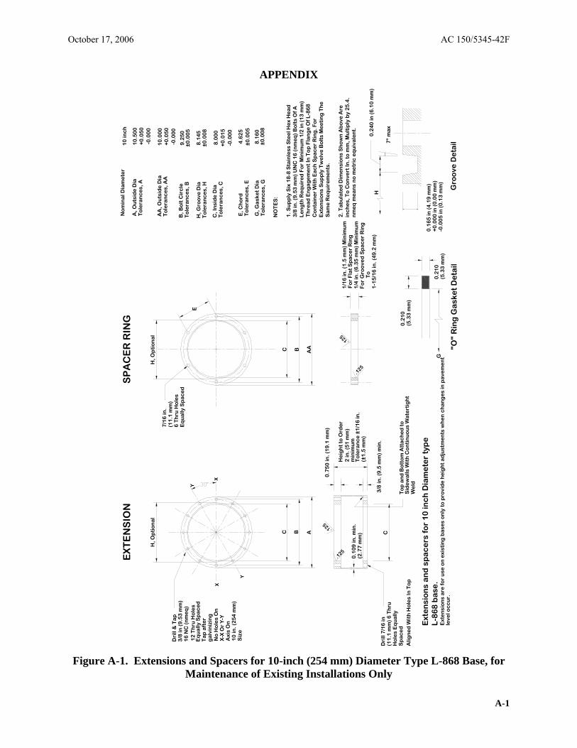
APPENDIX
EX
TE
NS
ION
S
PA
CE
R R
ING
N
om
ina
l Dia
me
ter
10
inc
h
A, O
uts
ide
Dia
10
.50
0
To
lera
nc
es,
A+
0.0
50
-0.0
00
C B AA
E
.125
.125
H, G
roo
ve D
ia8
.14
5
X
C, I
nsi
de
Dia
8.0
00
Siz
e
Dri
ll &
Ta
p3
/8 in
(9
.53
mm
)1
6 N
C (
nm
eq
)
Eq
ua
lly S
pa
ce
dT
ap
aft
er
ga
lvin
izin
g
7/1
6 in
.(1
1.1
mm
)6
Th
ru H
ole
sE
qu
ally
Sp
ac
ed
C B A
B, B
olt
Cir
cle
To
lera
nc
es,
B
To
lera
nc
es,
C
9.2
50
±0
.00
5
+0
.01
5-0
.00
0
Y
X
Y
12
Th
ru H
ole
s
No
Ho
les
On
X-X
Or
Y-Y
Axi
s O
n1
0 in
. (2
54
mm
)
H, O
pti
on
al
H, O
pti
on
al
To
lera
nc
es,
H
±0
.00
8
To
lera
nc
es,
AA
A
A, O
uts
ide
Dia
-0.0
00
10
.00
0+
0.0
50
min
imu
m
Dri
ll 7
/16
in(1
1.1
mm
) 6
Th
ruC
0.1
09
in. m
in.
3/8
in. (
9.5
mm
) m
in.
.125
.125
1-1
5/1
6 in
. (4
9.2
mm
)
E, C
ho
rd4
.62
5T
ole
ran
ce
s, E
±
0.0
05
G, G
ask
et
Dia
8.1
60
To
lera
nc
es,
G
±0
.00
8
NO
TE
S:
1. S
up
ply
Six
18
-8 S
tain
less
Ste
el H
ex
He
ad
3/8
in. (
9.5
3 m
m)
UN
C 1
6 (
nm
eq
) B
olt
s O
f AL
en
gth
Re
qu
ire
d F
or
Min
imu
m 1
/2 in
(1
3 m
m)
Th
rea
d E
ng
ag
em
en
t In
To
p F
lan
ge
Of
L-8
68
C
on
tain
er
Wit
h E
ac
h S
pa
ce
r R
ing
. Fo
rE
xte
nsi
on
s S
up
ply
Tw
elv
e B
olt
s M
ee
tin
g T
he
0
.75
0 in
. (1
9.1
mm
) S
am
e R
eq
uir
em
en
ts.
He
igh
t to
Ord
er
2 in
. (5
1 m
m)
2. T
ab
ula
ted
Dim
en
sio
ns
Sh
ow
n A
bo
ve A
re
1/1
6 in
. (1
.5 m
m)
Min
imu
min
ch
es,
To
Co
nve
rt In
. to
mm
, Mu
ltip
ly b
y 2
5.4
.F
or
Fla
t S
pa
ce
r R
ing
1/4
in. (
6.3
5 m
m)
Min
imu
mn
me
q m
ea
ns
no
me
tric
eq
uiv
ale
nt.
To
lera
nc
e ±
1/1
6 in
.(2
.77
mm
) (±
1.5
mm
) F
or
Gro
ove
d S
pa
ce
r R
ing
To
Ho
les
Eq
ua
llyS
pa
ce
d
To
p a
nd
Bo
tto
m A
tta
ch
ed
to
0
.21
0A
lign
ed
Wit
h H
ole
s In
To
p
Sid
ew
alls
Wit
h C
on
tin
uo
us
Wa
tert
igh
t(5
.33
mm
) W
eld
Ext
en
sio
ns
an
d s
pa
ce
rs f
or
10
inc
h D
iam
ete
r ty
pe
+0
.00
0 in
(0
.00
mm
) 0
.21
0G
-0
.00
5 in
(0
.13
mm
) L
-86
8 b
ase
.(5
.33
mm
)
0.1
65
in (
4.1
9 m
m)
H
0.2
40
in (
6.1
0 m
m)
7°
ma
x
Ext
en
sio
ns
are
fo
r u
se o
n e
xist
ing
ba
ses
on
ly t
o p
rovi
de
he
igh
t a
dju
stm
en
ts w
he
n c
ha
ng
es
in p
ave
me
nt
leve
l oc
cu
r.
"O"
Rin
g G
ask
et
De
tail
Gro
ove
De
tail
October 17, 2006 AC 150/5345-42F
Figure A-1. Extensions and Spacers for 10-inch (254 mm) Diameter Type L-868 Base, for Maintenance of Existing Installations Only
A-1

AC 150/5345-42F October 17, 2006
Intentionally left blank.
A-2