Embed Size (px)
Citation preview
U.S. Department of Transportation
Federal Aviation Administration
Advisory Circular
Subject: SPECIFICATION FOR OBSTRUCTION LIGHTING EQUIPMENT
Date: 09/12/06 Initiated by: AAS-100
AC No.: 150/5345-43F Change:
1. PURPOSE. This advisory circular (AC) contains the Federal Aviation Administration (FAA) specification for obstruction lighting equipment. 2. EFFECTIVE DATE. Effective 6 months after the date of this circular, only that equipment qualified per this specification will be listed in AC 150/5345-53, Airport Lighting Equipment Certification Program. 3. CANCELLATION. AC 150/5345-43E, Specification for Obstruction Lighting Equipment, dated October 19, 1995, is canceled. 4. APPLICATION. The specifications contained in this AC are recommended by the FAA in all applications involving development of this nature. For airport projects receiving Federal funds under the airport grant assistance program, the use of these standards is mandatory. 5. DEFINITIONS.
a. Beam Spread. The angle between the two directions in a plane for which the intensity is equal to 50 percent of the minimum specified peak beam effective intensity.
b. Vertical Aiming Angle. The angle between the horizontal and a straight line intersecting the beam at its maximum intensity.
c. Steady-Burning (fixed) Light. A light having constant luminous intensity when observed from a fixed point.
d. Effective Intensity. The effective intensity of a flashing light is equal to the intensity of a steady-burning (fixed) light of the same color that produces the same visual range under identical conditions of observation. 6. PRINCIPAL CHANGES.
a. Added a requirement for the use of ultraviolet and ozone resistant materials with xenon flashtubes.
b. Added a requirement for solar radiation resistant plastic parts and applicable testing.
c. Added a requirement for surge protection and testing for equipment with solid-state devices.
d. Added requirements from FAA Engineering Brief #67 as necessary to provide requirements for obstruction lighting using alternative light sources (ALDs).
e. Added optional radiated emissions requirements with no testing required.
7. METRIC UNITS. To promote an orderly transition to metric units, this AC includes both English and metric dimensions. The metric conversions may not be exact equivalents, and until there is an official changeover to the metric system, the English dimensions will govern.
8. COMMENTS OR SUGGESTIONS for improvements to this AC should be sent to:
Manager, Airport Engineering Division Federal Aviation Administration ATTN: AAS-100 800 Independence Avenue, S.W. Washington, DC 20591
9. COPIES OF THIS AC. The Office of Airport Safety and Standards makes this AC available online at www.faa.gov.
DAVID L. BENNETT Director of Airport Safety and Standards
09/12/06 AC 150/5345-43F
TABLE OF CONTENTS
CHAPTER 1. SCOPE AND CLASSIFICATION................................................................................... 1 1.1 SCOPE. ........................................................................................................................................... 1 1.2 EQUIPMENT CLASSIFICATION. ...................................................................................................... 1
CHAPTER 2. REFERENCED DOCUMENTS....................................................................................... 3 2.1 GENERAL....................................................................................................................................... 3 2.2 FAA ADVISORY CIRCULARS (ACS).............................................................................................. 3 2.3 FAA ENGINEERING BRIEFS........................................................................................................... 3 2.4 MILITARY STANDARDS AND SPECIFICATIONS. ............................................................................. 3 2.5 CODE OF FEDERAL REGULATIONS (CFR). .................................................................................... 3 2.6 INSTITUTE OF ELECTRICAL AND ELECTRONICS ENGINEERS (IEEE) PUBLICATIONS.................... 3 2.7 INTERNATIONAL STANDARDIZATION ORGANIZATION (ISO) PUBLICATIONS............................... 3 2.8 INTERNATIONAL CIVIL AVIATION ORGANIZATION (ICAO). ........................................................ 3 2.9 ILLUMINATING ENGINEERING SOCIETY (IES)............................................................................... 3
CHAPTER 3. EQUIPMENT REQUIREMENTS................................................................................... 7 3.1 GENERAL....................................................................................................................................... 7 3.2 ENVIRONMENTAL REQUIREMENTS. .............................................................................................. 7 3.3 DESIGN REQUIREMENTS................................................................................................................ 7
3.3.1 Light Unit.............................................................................................................................. 7 3.3.2 Light Covers.......................................................................................................................... 7 3.3.3 Light Colors. ......................................................................................................................... 7 3.3.4 Aiming (for L-856 and L-857).............................................................................................. 8 3.3.5 Control Unit. ......................................................................................................................... 8 3.3.6 Input Voltage. ....................................................................................................................... 9 3.3.7 Performance Criteria. ............................................................................................................ 9 3.3.8 Transient Protection. ............................................................................................................. 9 3.3.9 Radiated Emissions. ............................................................................................................ 10 3.3.10 Warning Labels. .................................................................................................................. 10 3.3.11 Interlock Switches............................................................................................................... 10 3.3.12 Nameplate. .......................................................................................................................... 10 3.3.13 Optional Arctic Kit.............................................................................................................. 10 3.3.14 Component Ratings............................................................................................................. 11 3.3.15 Leakage Current.................................................................................................................. 11
3.4 PERFORMANCE REQUIREMENTS.................................................................................................. 11 3.4.1 Photometric. ........................................................................................................................ 11 3.4.2 Flash Rate and Duration...................................................................................................... 14 3.4.3 System Flashing Requirements. .......................................................................................... 15 3.4.4 Intensity Step Changing. ..................................................................................................... 16
3.5 INSTRUCTION MANUAL............................................................................................................... 16 CHAPTER 4. EQUIPMENT QUALIFICATION REQUIREMENTS............................................... 19
4.1 QUALIFICATION PROCEDURES. ................................................................................................... 19 4.2 QUALIFICATION TESTS................................................................................................................ 19
4.2.1 Photometric Test. ................................................................................................................ 19 4.2.2 High Temperature Test. ...................................................................................................... 20
i
AC 150/5345-43F 09/12/06
4.2.3 Low Temperature Test. ....................................................................................................... 20 4.2.4 Rain Test. ............................................................................................................................ 21 4.2.5 Wind Test............................................................................................................................ 21 4.2.6 Humidity Test. .................................................................................................................... 21 4.2.7 Salt Fog Test. ...................................................................................................................... 21 4.2.8 Sunshine Test. ..................................................................................................................... 21 4.2.9 Transient Protection Test. ................................................................................................... 22 4.2.10 System Operational Test. .................................................................................................... 22 4.2.11 Leakage Current Test. ......................................................................................................... 23 4.2.12 Visual Examination............................................................................................................. 23
CHAPTER 5. PRODUCTION TEST REQUIREMENTS................................................................... 25 5.1 SYSTEM PRODUCTION TESTS. .................................................................................................... 25 5.2 INCANDESCENT LIGHT UNIT PRODUCTION TESTS. .................................................................... 25 5.3 ALTERNATIVE LIGHTING DEVICES (ALD). ................................................................................ 25 5.4 DISCHARGE LIGHT UNIT PRODUCTION TEST. ............................................................................ 25 5.5 PRODUCTION OPERATIONAL TEST. ............................................................................................ 25 5.6 PRODUCTION PHOTOMETRIC TEST............................................................................................. 26 5.7 PRODUCTION TEST RECORDS..................................................................................................... 27 5.8 PRODUCTION TEST EQUIPMENT. ................................................................................................ 27
LIST OF TABLES
Table 1. L-856 Intensity Requirements...................................................................................................... 13 Table 2. L-857 Intensity Requirements...................................................................................................... 13 Table 3. L-865 Intensity Requirements...................................................................................................... 14 Table 4. Flash Characteristics for Obstruction Lights ............................................................................... 15 Table 5. L-856/L-857 Production Photometric Requirements................................................................... 26 Table 6. L-865/866/864(1) /885(1) Production Photometric Requirements. ................................................ 26
ii
09/12/06 AC 150/5345-43F
CHAPTER 1. SCOPE AND CLASSIFICATION.
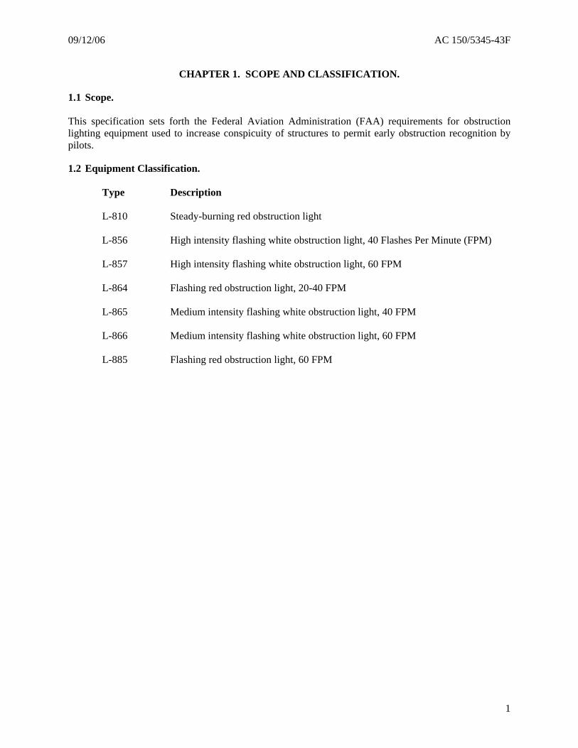
1.1 Scope. This specification sets forth the Federal Aviation Administration (FAA) requirements for obstruction lighting equipment used to increase conspicuity of structures to permit early obstruction recognition by pilots.
1.2 Equipment Classification.
Type Description
L-810 Steady-burning red obstruction light L-856 High intensity flashing white obstruction light, 40 Flashes Per Minute (FPM) L-857 High intensity flashing white obstruction light, 60 FPM L-864 Flashing red obstruction light, 20-40 FPM L-865 Medium intensity flashing white obstruction light, 40 FPM L-866 Medium intensity flashing white obstruction light, 60 FPM L-885 Flashing red obstruction light, 60 FPM
1

AC 150/5345-43F 09/12/06
Intentionally left blank.
2
09/12/06 AC 150/5345-43F
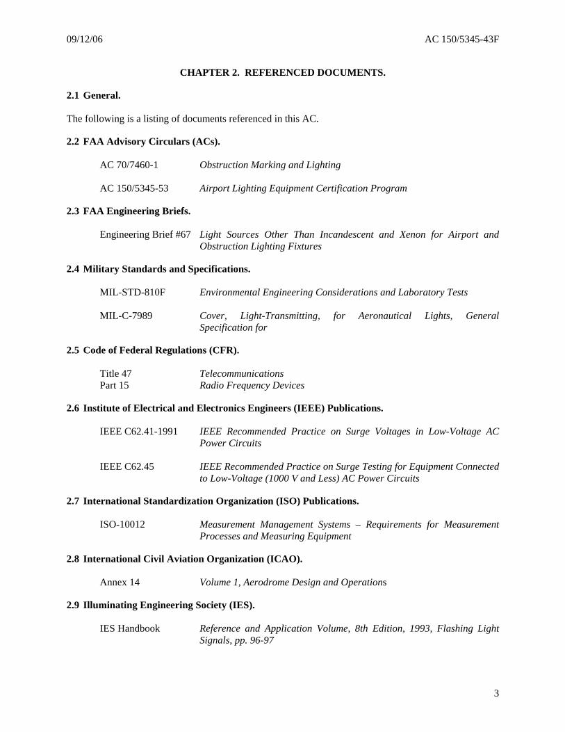
CHAPTER 2. REFERENCED DOCUMENTS.
2.1 General. The following is a listing of documents referenced in this AC.
2.2 FAA Advisory Circulars (ACs).
AC 70/7460-1 Obstruction Marking and Lighting
AC 150/5345-53 Airport Lighting Equipment Certification Program
2.3 FAA Engineering Briefs.
Engineering Brief #67 Light Sources Other Than Incandescent and Xenon for Airport and Obstruction Lighting Fixtures
2.4 Military Standards and Specifications.
MIL-STD-810F Environmental Engineering Considerations and Laboratory Tests
MIL-C-7989 Cover, Light-Transmitting, for Aeronautical Lights, General Specification for
2.5 Code of Federal Regulations (CFR).
Title 47 Telecommunications Part 15 Radio Frequency Devices
2.6 Institute of Electrical and Electronics Engineers (IEEE) Publications.
IEEE C62.41-1991 IEEE Recommended Practice on Surge Voltages in Low-Voltage AC Power Circuits
IEEE C62.45 IEEE Recommended Practice on Surge Testing for Equipment Connected
to Low-Voltage (1000 V and Less) AC Power Circuits
2.7 International Standardization Organization (ISO) Publications.
ISO-10012 Measurement Management Systems – Requirements for Measurement Processes and Measuring Equipment
2.8 International Civil Aviation Organization (ICAO).
Annex 14 Volume 1, Aerodrome Design and Operations
2.9 Illuminating Engineering Society (IES).
IES Handbook Reference and Application Volume, 8th Edition, 1993, Flashing Light Signals, pp. 96-97
3
AC 150/5345-43F 09/12/06
Copies of FAA ACs may be obtained from:
U.S. Department of Transportation Subsequent Distribution Office Ardmore East Business Center 3341 Q 75th Ave. Landover, MD 20785
Tel: (301) 322-4961 FAX: (301) 386-5394 Website: www.faa.gov
Copies of military standards and specifications may be obtained from:
DAPS/DODSSP Building 4, Section D 700 Robbins Avenue Philadelphia, PA 19111-5094 Tel: (215) 697-2179 FAX: (215) 697-1460 Website: dodssp.daps.dla.mil
Copies of IEEE standards may be obtained from:
IEEE Customer Service Center 445 Hoes Lane P.O. Box 1331 Piscataway, NJ 08855-1331 Tel: (800) 678-4333 FAX: (732) 981-0060 (Worldwide) FAX: (732) 981-9667 E-mail: [email protected] Website: shop.ieee.org/ieeestore
Copies of the ISO document are available online from:
Website: www.iso.ch
Copies of ICAO documents may be obtained from:
ICAO, Document Sales Unit 999 University Street Montreal, Quebec, Canada H3C 5H7 Telephone: +1 (514) 954-8022 FAX: +1(514) 954-6769 E-mail: [email protected] Website: www.icao.int
4
09/12/06 AC 150/5345-43F
Copies of IES of North America (IESNA) documents may be obtained from:
Website: www.techstreet.com
or Website: www.iesna.org/shop/
5
AC 150/5345-43F 09/12/06
Intentionally left blank.
6
09/12/06 AC 150/5345-43F
CHAPTER 3. EQUIPMENT REQUIREMENTS.
3.1 General. This section addresses environmental, design, and photometric requirements for obstruction light equipment. Criteria for selecting the proper obstruction lighting equipment, installation tolerances, and administrative information are in AC 70/7460-1, Obstruction Marking and Lighting.
3.2 Environmental Requirements. Obstruction lighting equipment must be designed for continuous operation under the following conditions:
a. Temperature. Storage/shipping: -67 degrees Fahrenheit (F) (-55 degrees Celsius (C)) to 130 degrees F (55 degrees C). Operating: -40 degrees F (-40 degrees C) to 130 degrees F (55 degrees C).
b. Humidity. 95 percent relative humidity.
c. Wind. Wind speeds up to 150 miles per hour (mph) (240 kilometeres per hour (kmph)).
d. Wind-blown Rain. Exposure to wind-blown rain from any direction.
e. Salt Fog. Exposure to salt-laden atmosphere.
f. Sunshine. Exposure to solar radiation.
3.3 Design Requirements.
3.3.1 Light Unit. The light unit must be lightweight and designed for easy servicing and lamp (or flashtube) replacement. Materials used within the light unit must be selected for compatibility with their environment. All plastic lens parts (including gaskets), that are exposed to ultraviolet radiation or ozone gas must not change color, crack, check, disintegrate, or be otherwise degraded (photometry must remain compliant) and meet the equipment warranty requirements of AC 150/5345-53, Appendix 2. Each light unit must be an independent unit and must flash at the specified intensity or at its highest intensity when control signals are absent.
3.3.2 Light Covers. Light-transmitting covers for light units must be per the requirements in MIL-C-7989. In addition, if plastic covers are used, they must be resistant to checking, crazing, or color changes caused by ultraviolet radiation or ozone gas exposure.
3.3.3 Light Colors. The aviation red must be per ICAO Annex 14, Volume 1, Appendix 1, Colours for Aeronautical Ground Lights, at operating temperature within the following chromaticity boundaries: purple boundary y = 0.980 - x
7
AC 150/5345-43F 09/12/06
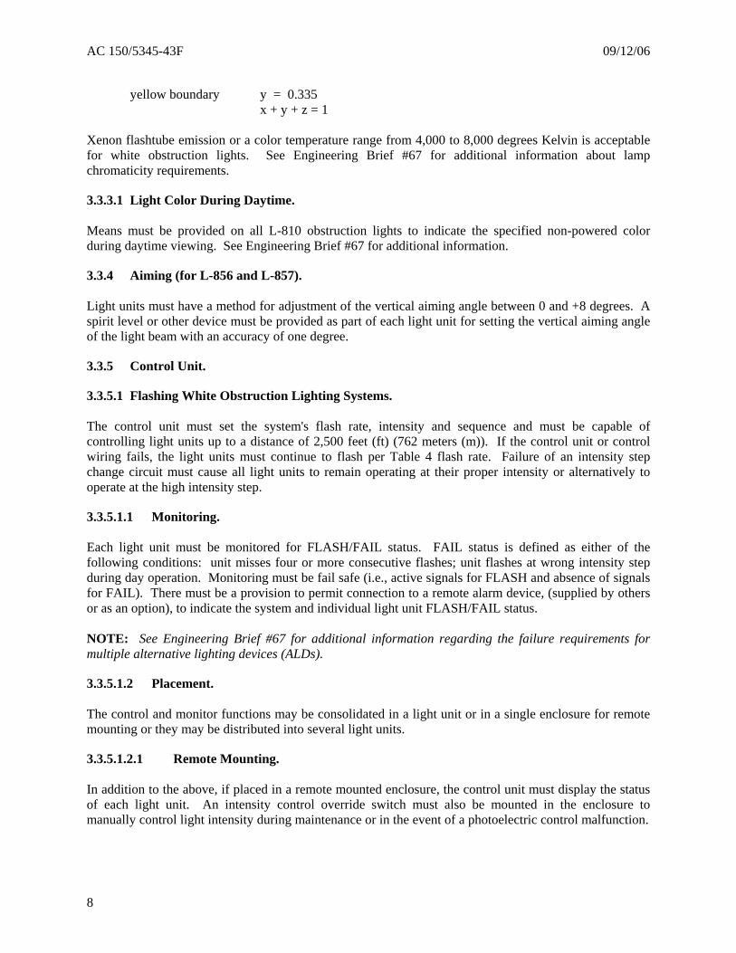
yellow boundary y = 0.335 x + y + z = 1 Xenon flashtube emission or a color temperature range from 4,000 to 8,000 degrees Kelvin is acceptable for white obstruction lights. See Engineering Brief #67 for additional information about lamp chromaticity requirements.
3.3.3.1 Light Color During Daytime. Means must be provided on all L-810 obstruction lights to indicate the specified non-powered color during daytime viewing. See Engineering Brief #67 for additional information.
3.3.4 Aiming (for L-856 and L-857). Light units must have a method for adjustment of the vertical aiming angle between 0 and +8 degrees. A spirit level or other device must be provided as part of each light unit for setting the vertical aiming angle of the light beam with an accuracy of one degree.
3.3.5 Control Unit.
3.3.5.1 Flashing White Obstruction Lighting Systems. The control unit must set the system's flash rate, intensity and sequence and must be capable of controlling light units up to a distance of 2,500 feet (ft) (762 meters (m)). If the control unit or control wiring fails, the light units must continue to flash per Table 4 flash rate. Failure of an intensity step change circuit must cause all light units to remain operating at their proper intensity or alternatively to operate at the high intensity step.
3.3.5.1.1 Monitoring. Each light unit must be monitored for FLASH/FAIL status. FAIL status is defined as either of the following conditions: unit misses four or more consecutive flashes; unit flashes at wrong intensity step during day operation. Monitoring must be fail safe (i.e., active signals for FLASH and absence of signals for FAIL). There must be a provision to permit connection to a remote alarm device, (supplied by others or as an option), to indicate the system and individual light unit FLASH/FAIL status. NOTE: See Engineering Brief #67 for additional information regarding the failure requirements for multiple alternative lighting devices (ALDs).
3.3.5.1.2 Placement. The control and monitor functions may be consolidated in a light unit or in a single enclosure for remote mounting or they may be distributed into several light units.
3.3.5.1.2.1 Remote Mounting. In addition to the above, if placed in a remote mounted enclosure, the control unit must display the status of each light unit. An intensity control override switch must also be mounted in the enclosure to manually control light intensity during maintenance or in the event of a photoelectric control malfunction.
8
09/12/06 AC 150/5345-43F
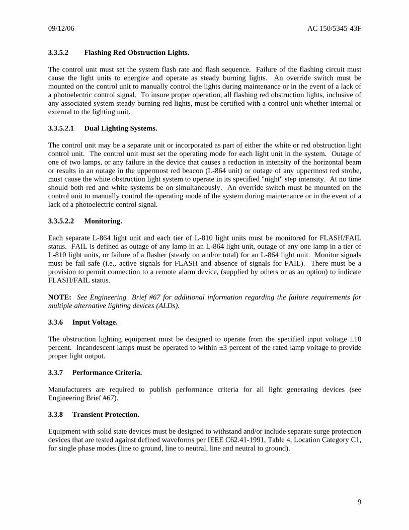
3.3.5.2 Flashing Red Obstruction Lights. The control unit must set the system flash rate and flash sequence. Failure of the flashing circuit must cause the light units to energize and operate as steady burning lights. An override switch must be mounted on the control unit to manually control the lights during maintenance or in the event of a lack of a photoelectric control signal. To insure proper operation, all flashing red obstruction lights, inclusive of any associated system steady burning red lights, must be certified with a control unit whether internal or external to the lighting unit.
3.3.5.2.1 Dual Lighting Systems. The control unit may be a separate unit or incorporated as part of either the white or red obstruction light control unit. The control unit must set the operating mode for each light unit in the system. Outage of one of two lamps, or any failure in the device that causes a reduction in intensity of the horizontal beam or results in an outage in the uppermost red beacon (L-864 unit) or outage of any uppermost red strobe, must cause the white obstruction light system to operate in its specified "night" step intensity. At no time should both red and white systems be on simultaneously. An override switch must be mounted on the control unit to manually control the operating mode of the system during maintenance or in the event of a lack of a photoelectric control signal.
3.3.5.2.2 Monitoring. Each separate L-864 light unit and each tier of L-810 light units must be monitored for FLASH/FAIL status. FAIL is defined as outage of any lamp in an L-864 light unit, outage of any one lamp in a tier of L-810 light units, or failure of a flasher (steady on and/or total) for an L-864 light unit. Monitor signals must be fail safe (i.e., active signals for FLASH and absence of signals for FAIL). There must be a provision to permit connection to a remote alarm device, (supplied by others or as an option) to indicate FLASH/FAIL status. NOTE: See Engineering Brief #67 for additional information regarding the failure requirements for multiple alternative lighting devices (ALDs).
3.3.6 Input Voltage. The obstruction lighting equipment must be designed to operate from the specified input voltage ±10 percent. Incandescent lamps must be operated to within ±3 percent of the rated lamp voltage to provide proper light output.
3.3.7 Performance Criteria. Manufacturers are required to publish performance criteria for all light generating devices (see Engineering Brief #67).
3.3.8 Transient Protection. Equipment with solid state devices must be designed to withstand and/or include separate surge protection devices that are tested against defined waveforms per IEEE C62.41-1991, Table 4, Location Category C1, for single phase modes (line to ground, line to neutral, line and neutral to ground).
9
AC 150/5345-43F 09/12/06
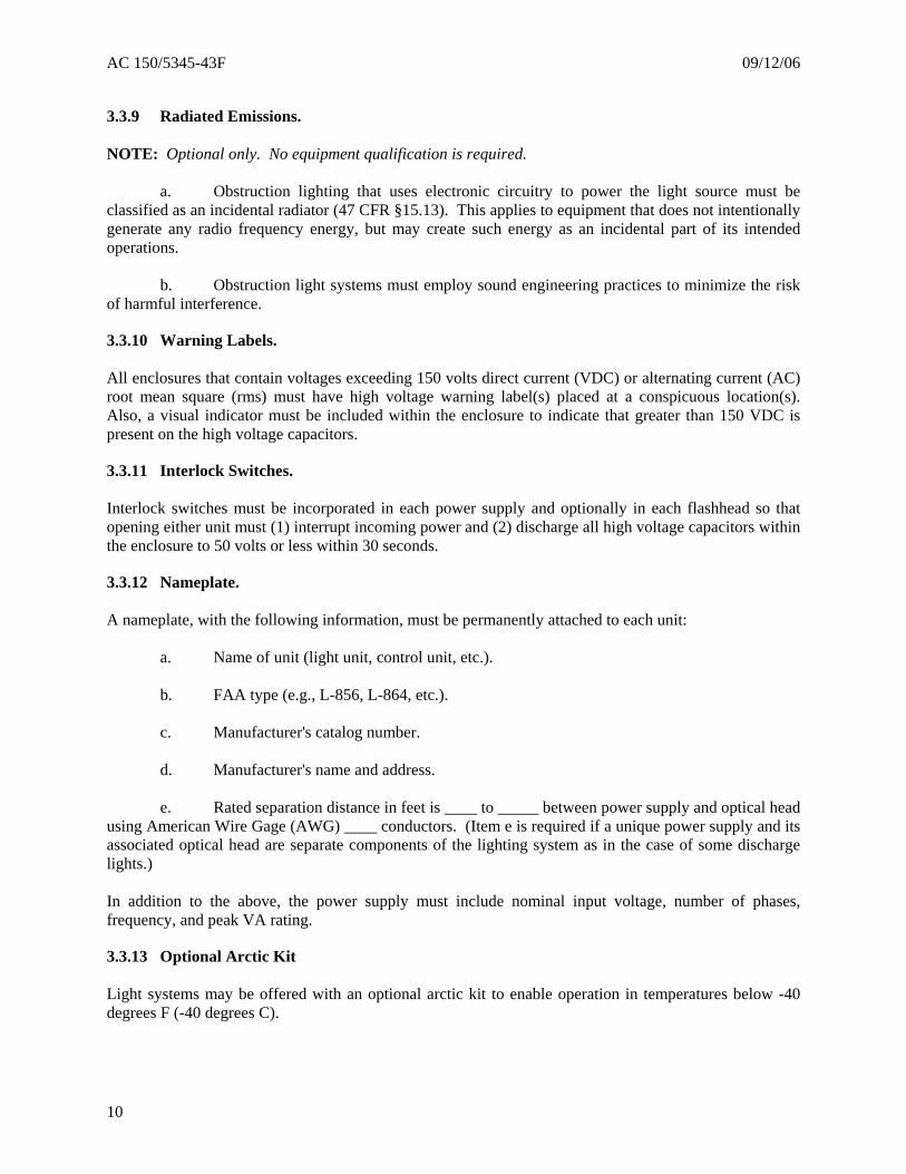
3.3.9 Radiated Emissions. NOTE: Optional only. No equipment qualification is required.
a. Obstruction lighting that uses electronic circuitry to power the light source must be classified as an incidental radiator (47 CFR §15.13). This applies to equipment that does not intentionally generate any radio frequency energy, but may create such energy as an incidental part of its intended operations.
b. Obstruction light systems must employ sound engineering practices to minimize the risk
of harmful interference.
3.3.10 Warning Labels. All enclosures that contain voltages exceeding 150 volts direct current (VDC) or alternating current (AC) root mean square (rms) must have high voltage warning label(s) placed at a conspicuous location(s). Also, a visual indicator must be included within the enclosure to indicate that greater than 150 VDC is present on the high voltage capacitors.
3.3.11 Interlock Switches. Interlock switches must be incorporated in each power supply and optionally in each flashhead so that opening either unit must (1) interrupt incoming power and (2) discharge all high voltage capacitors within the enclosure to 50 volts or less within 30 seconds.
3.3.12 Nameplate. A nameplate, with the following information, must be permanently attached to each unit:
a. Name of unit (light unit, control unit, etc.).
b. FAA type (e.g., L-856, L-864, etc.).
c. Manufacturer's catalog number.
d. Manufacturer's name and address.
e. Rated separation distance in feet is ____ to _____ between power supply and optical head using American Wire Gage (AWG) ____ conductors. (Item e is required if a unique power supply and its associated optical head are separate components of the lighting system as in the case of some discharge lights.) In addition to the above, the power supply must include nominal input voltage, number of phases, frequency, and peak VA rating.
3.3.13 Optional Arctic Kit
Light systems may be offered with an optional arctic kit to enable operation in temperatures below -40 degrees F (-40 degrees C).
10
09/12/06 AC 150/5345-43F
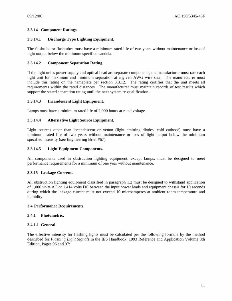
3.3.14 Component Ratings.
3.3.14.1 Discharge Type Lighting Equipment. The flashtube or flashtubes must have a minimum rated life of two years without maintenance or loss of light output below the minimum specified candela.
3.3.14.2 Component Separation Rating. If the light unit's power supply and optical head are separate components, the manufacturer must rate each light unit for maximum and minimum separation at a given AWG wire size. The manufacturer must include this rating on the nameplate per section 3.3.12. The rating certifies that the unit meets all requirements within the rated distances. The manufacturer must maintain records of test results which support the stated separation rating until the next system re-qualification.
3.3.14.3 Incandescent Light Equipment. Lamps must have a minimum rated life of 2,000 hours at rated voltage.
3.3.14.4 Alternative Light Source Equipment. Light sources other than incandescent or xenon (light emitting diodes, cold cathode) must have a minimum rated life of two years without maintenance or loss of light output below the minimum specified intensity (see Engineering Brief #67).
3.3.14.5 Light Equipment Components. All components used in obstruction lighting equipment, except lamps, must be designed to meet performance requirements for a minimum of one year without maintenance.
3.3.15 Leakage Current. All obstruction lighting equipment classified in paragraph 1.2 must be designed to withstand application of 1,000 volts AC or 1,414 volts DC between the input power leads and equipment chassis for 10 seconds during which the leakage current must not exceed 10 microamperes at ambient room temperature and humidity.
3.4 Performance Requirements.
3.4.1 Photometric.
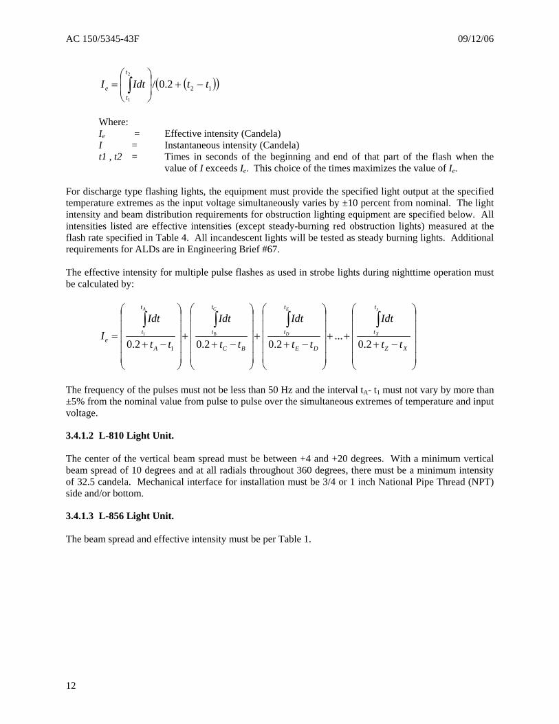
3.4.1.1 General. The effective intensity for flashing lights must be calculated per the following formula by the method described for Flashing Light Signals in the IES Handbook, 1993 Reference and Application Volume 8th Edition, Pages 96 and 97:
11
AC 150/5345-43F 09/12/06
( )( )122.0/2
1
ttIdtIt
te −+⎟
⎟⎠
⎞⎜⎜⎝
⎛= ∫
Where: Ie = Effective intensity (Candela) I = Instantaneous intensity (Candela) t1 , t2 = Times in seconds of the beginning and end of that part of the flash when the
value of I exceeds Ie. This choice of the times maximizes the value of Ie. For discharge type flashing lights, the equipment must provide the specified light output at the specified temperature extremes as the input voltage simultaneously varies by ±10 percent from nominal. The light intensity and beam distribution requirements for obstruction lighting equipment are specified below. All intensities listed are effective intensities (except steady-burning red obstruction lights) measured at the flash rate specified in Table 4. All incandescent lights will be tested as steady burning lights. Additional requirements for ALDs are in Engineering Brief #67. The effective intensity for multiple pulse flashes as used in strobe lights during nighttime operation must be calculated by:
⎟⎟⎟⎟⎟
⎠
⎞
⎜⎜⎜⎜⎜
⎝
⎛
−+++
⎟⎟⎟⎟⎟
⎠
⎞
⎜⎜⎜⎜⎜
⎝
⎛
−++
⎟⎟⎟⎟⎟
⎠
⎞
⎜⎜⎜⎜⎜
⎝
⎛
−++
⎟⎟⎟⎟⎟
⎠
⎞
⎜⎜⎜⎜⎜
⎝
⎛
−+=
∫∫∫∫XZ
t
t
DE
t
t
BC
t
t
A
t
te tt
Idt
tt
Idt
tt
Idt
tt
IdtI
z
X
E
D
C
B
A
2.0...
2.02.02.0 1
1
The frequency of the pulses must not be less than 50 Hz and the interval tA- t1 must not vary by more than ±5% from the nominal value from pulse to pulse over the simultaneous extremes of temperature and input voltage.
3.4.1.2 L-810 Light Unit. The center of the vertical beam spread must be between +4 and +20 degrees. With a minimum vertical beam spread of 10 degrees and at all radials throughout 360 degrees, there must be a minimum intensity of 32.5 candela. Mechanical interface for installation must be 3/4 or 1 inch National Pipe Thread (NPT) side and/or bottom.
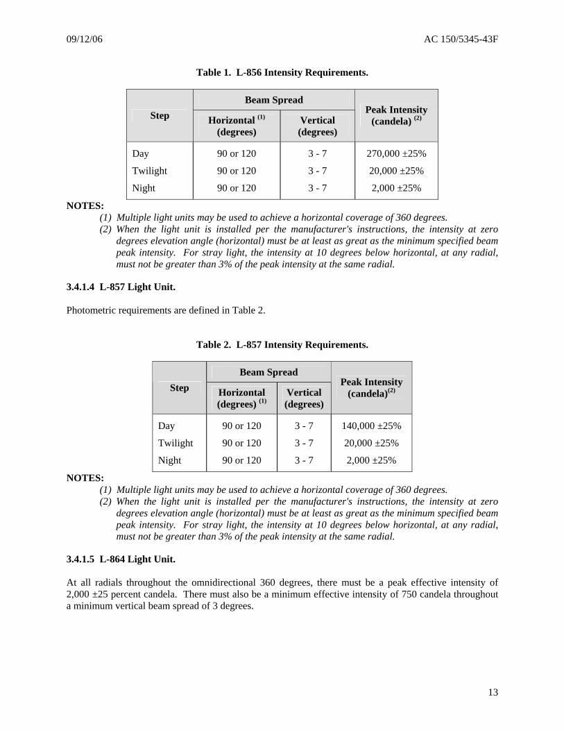
3.4.1.3 L-856 Light Unit. The beam spread and effective intensity must be per Table 1.
12
09/12/06 AC 150/5345-43F
Table 1. L-856 Intensity Requirements.
Beam Spread Step Horizontal (1)
(degrees) Vertical (degrees)
Peak Intensity (candela) (2)
Day
Twilight
Night
90 or 120
90 or 120
90 or 120
3 - 7
3 - 7
3 - 7
270,000 ±25%
20,000 ±25%
2,000 ±25%
NOTES: (1) Multiple light units may be used to achieve a horizontal coverage of 360 degrees. (2) When the light unit is installed per the manufacturer's instructions, the intensity at zero
degrees elevation angle (horizontal) must be at least as great as the minimum specified beam peak intensity. For stray light, the intensity at 10 degrees below horizontal, at any radial, must not be greater than 3% of the peak intensity at the same radial.
3.4.1.4 L-857 Light Unit. Photometric requirements are defined in Table 2.
Table 2. L-857 Intensity Requirements.
Beam Spread Step Horizontal
(degrees) (1)Vertical (degrees)
Peak Intensity (candela)(2)
Day
Twilight
Night
90 or 120
90 or 120
90 or 120
3 - 7
3 - 7
3 - 7
140,000 ±25%
20,000 ±25%
2,000 ±25%
NOTES: (1) Multiple light units may be used to achieve a horizontal coverage of 360 degrees. (2) When the light unit is installed per the manufacturer's instructions, the intensity at zero
degrees elevation angle (horizontal) must be at least as great as the minimum specified beam peak intensity. For stray light, the intensity at 10 degrees below horizontal, at any radial, must not be greater than 3% of the peak intensity at the same radial.
3.4.1.5 L-864 Light Unit. At all radials throughout the omnidirectional 360 degrees, there must be a peak effective intensity of 2,000 ±25 percent candela. There must also be a minimum effective intensity of 750 candela throughout a minimum vertical beam spread of 3 degrees.
13
AC 150/5345-43F 09/12/06
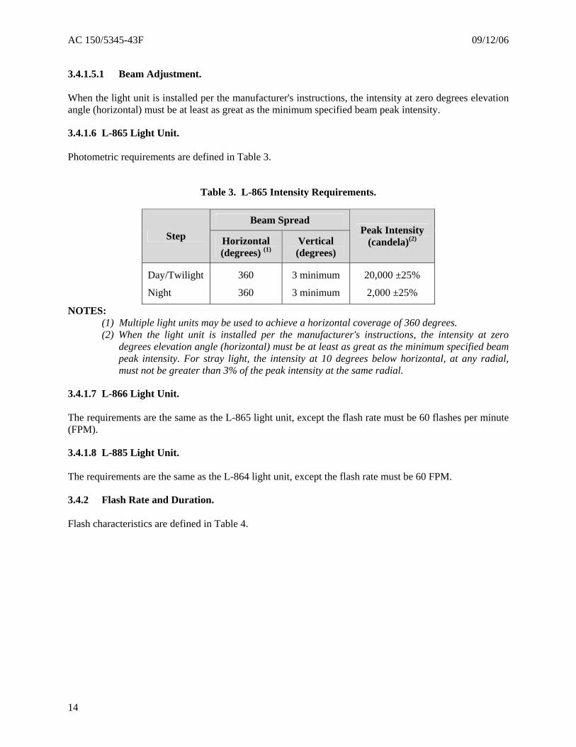
3.4.1.5.1 Beam Adjustment. When the light unit is installed per the manufacturer's instructions, the intensity at zero degrees elevation angle (horizontal) must be at least as great as the minimum specified beam peak intensity.
3.4.1.6 L-865 Light Unit. Photometric requirements are defined in Table 3.
Table 3. L-865 Intensity Requirements.
Beam Spread Step Horizontal
(degrees) (1)Vertical (degrees)
Peak Intensity (candela)(2)
Day/Twilight
Night
360
360
3 minimum
3 minimum
20,000 ±25%
2,000 ±25%
NOTES: (1) Multiple light units may be used to achieve a horizontal coverage of 360 degrees. (2) When the light unit is installed per the manufacturer's instructions, the intensity at zero
degrees elevation angle (horizontal) must be at least as great as the minimum specified beam peak intensity. For stray light, the intensity at 10 degrees below horizontal, at any radial, must not be greater than 3% of the peak intensity at the same radial.
3.4.1.7 L-866 Light Unit. The requirements are the same as the L-865 light unit, except the flash rate must be 60 flashes per minute (FPM).
3.4.1.8 L-885 Light Unit. The requirements are the same as the L-864 light unit, except the flash rate must be 60 FPM.
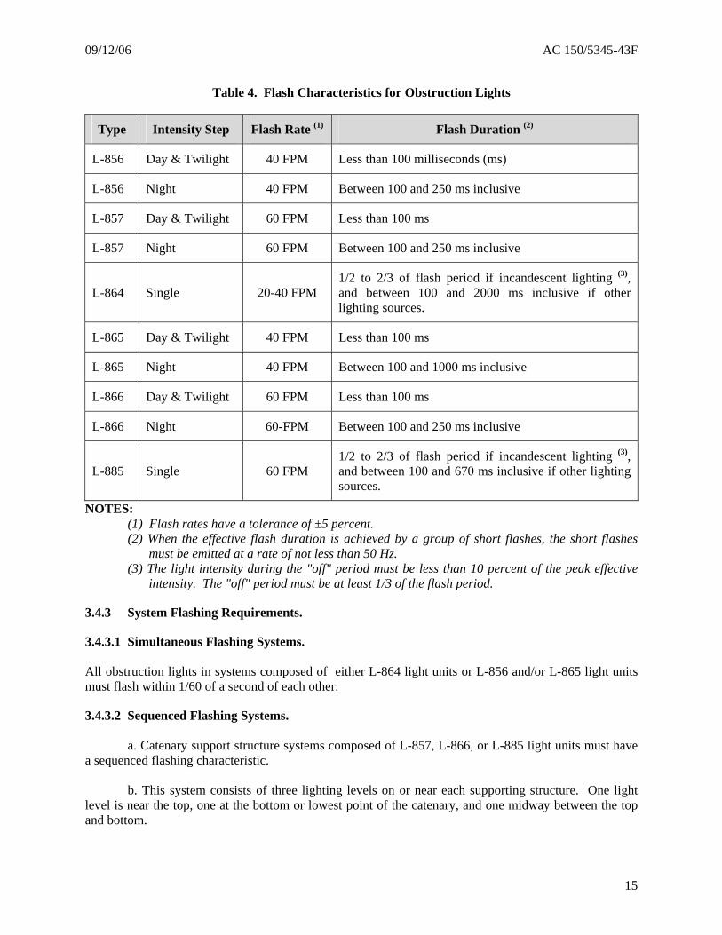
3.4.2 Flash Rate and Duration. Flash characteristics are defined in Table 4.
14
09/12/06 AC 150/5345-43F
Table 4. Flash Characteristics for Obstruction Lights
Type Intensity Step Flash Rate (1) Flash Duration (2)
L-856 Day & Twilight 40 FPM Less than 100 milliseconds (ms)
L-856 Night 40 FPM Between 100 and 250 ms inclusive
L-857 Day & Twilight 60 FPM Less than 100 ms
L-857 Night 60 FPM Between 100 and 250 ms inclusive
L-864 Single 20-40 FPM 1/2 to 2/3 of flash period if incandescent lighting (3), and between 100 and 2000 ms inclusive if other lighting sources.
L-865 Day & Twilight 40 FPM Less than 100 ms
L-865 Night 40 FPM Between 100 and 1000 ms inclusive
L-866 Day & Twilight 60 FPM Less than 100 ms
L-866 Night 60-FPM Between 100 and 250 ms inclusive
L-885 Single 60 FPM 1/2 to 2/3 of flash period if incandescent lighting (3), and between 100 and 670 ms inclusive if other lighting sources.
NOTES: (1) Flash rates have a tolerance of ±5 percent. (2) When the effective flash duration is achieved by a group of short flashes, the short flashes
must be emitted at a rate of not less than 50 Hz. (3) The light intensity during the "off" period must be less than 10 percent of the peak effective
intensity. The "off" period must be at least 1/3 of the flash period.
3.4.3 System Flashing Requirements.
3.4.3.1 Simultaneous Flashing Systems. All obstruction lights in systems composed of either L-864 light units or L-856 and/or L-865 light units must flash within 1/60 of a second of each other.
3.4.3.2 Sequenced Flashing Systems.
a. Catenary support structure systems composed of L-857, L-866, or L-885 light units must have a sequenced flashing characteristic.
b. This system consists of three lighting levels on or near each supporting structure. One light
level is near the top, one at the bottom or lowest point of the catenary, and one midway between the top and bottom.
15
AC 150/5345-43F 09/12/06
c. The flash sequence must be middle, top, and bottom. d. The interval between top and bottom flashes must be about twice the interval between middle
and top flashes. e. The interval between the end of one sequence and the beginning of the next must be about 10
times the interval between middle and top flashes. f. The time for the completion of one cycle must be one second (±5 percent).
3.4.4 Intensity Step Changing.
3.4.4.1 White Obstruction Lights. The light unit intensity must be controlled by a photocell facing the northern (polar) sky. White obstruction lights must automatically change intensity steps when the ambient light changes as follows: a. From day intensity to twilight intensity when the illumination decreases below 60 foot-candles (645.8 lux) but before it reaches 35 foot-candles (376.7 lux). b. From twilight intensity to night intensity when the illumination decreases below 5 foot-candles (53.8 lux) but before it reaches 2 foot-candles (21.5 lux). c. From night intensity to twilight intensity when the illumination increases above 2 foot-candles (21.5 lux) but before it reaches 5 foot-candles (53.8 lux). d. From twilight intensity to day intensity when the illumination increases above 35 foot-candles (376.7 lux) but before it reaches 60 foot-candles (645.8 lux).
3.4.4.2 Red Obstruction Lights. If automatic control is utilized, the light unit must turn on when the ambient light decreases to not less than 35 foot-candles (367.7 lux) and turn off when the ambient light increases to not more than 60 foot-candles (645.8 lux). Single L-810 light units are controlled in a manner compatible with the particular installation.
3.4.4.3 Dual Obstruction Lighting System. White obstruction lights must turn off and red obstruction lights must turn on when the ambient light changes from twilight to night per paragraph 3.4.4.1b. Red obstruction lights must turn off and white obstruction lights must turn on when the ambient light changes from night to twilight per paragraph 3.4.4.1c.
3.5 Instruction Manual. An instruction manual containing the following information must be furnished with all obstruction lighting equipment:
a. Complete system schematic and wiring diagrams showing all components cross-indexed to the parts list.
16
09/12/06 AC 150/5345-43F
b. Complete parts list of field replaceable parts with applicable rating and characteristics of each part, and with the component manufacturer's part number as appropriate.
c. Installation instructions, including leveling and aiming of light units.
d. Maintenance instructions, including lamp or flashtube replacement, theory of operation, troubleshooting charts and, as appropriate, conspicuous warnings about alignment and replacement of lamps and light units with other than manufacturer recommended items. Explanation of testing requirements regarding light units with specific lamps must be provided in the text. A discussion must be included about mixing light units as replacements with other manufacturers’ units with emphasis on assuring that system design of obstruction lighting is not degraded.
e. Operating instructions.
17
AC 150/5345-43F 09/12/06
Intentionally left blank.
18
09/12/06 AC 150/5345-43F
CHAPTER 4. EQUIPMENT QUALIFICATION REQUIREMENTS.
4.1 Qualification Procedures. Procedures for qualifying equipment to be furnished under the Federal grant assistance program for airports are contained in AC 150/5345-53, Airport Lighting Equipment Certification Program.
4.2 Qualification Tests. Qualification tests must be conducted on the light unit in the following order:
a. Initial photometric test, per paragraph 4.2.1
b. Environmental tests, per paragraphs 4.2.2, 4.2.3, 4.2.4, 4.2.5, 4.2.6, 4.2.7, and 4.2.8 (in any order)
c. 1000 hours of continuous operation, per paragraph 4.2.10
d. System Operational Test, per paragraph 4.2.10
e. Leakage Current Test, per paragraph 4.2.11
f. Sampling Photometric Test, per paragraph 4.2.1
g. Visual examination, per paragraph 4.2.12
h. Transient Protection Test, per paragraph 4.2.9. The equipment may be damaged by this
test. It should only be performed when testing per paragraphs a though c above is complete. Sample photometric and system operational tests must be conducted after completion of all environmental tests. The same unit(s) must be used throughout the tests. The following tests are required to demonstrate compliance with this specification. The tests may be run on the control unit, power supply, and a single light unit, with a simulated load replacing the other light units. Equipment tested must be as a complete system.
4.2.1 Photometric Test.
a. A full photometric test as described in this section must be performed before all environmental tests.
NOTE: To verify proper color correction, photometric testing conducted on alternative light source fixtures must be done with a detector having an up to date calibration including spectral response data (see Engineering Brief #67).
b. A sampling photometric retest must be conducted after the unit has been operated
continuously for 1000 hours with normal (12 hour) day/night cycling. This sampling must consist of measuring the vertical beam pattern for compliance with photometric requirements at a minimum of two of the previously tested horizontal radials.
c. Light units must be energized by the system power supply and control unit, and must be
tested for compliance with photometric requirements.
19
AC 150/5345-43F 09/12/06
d. For alternative light source equipment high temperature testing, see Engineering Brief
#67.
e. Incandescent lamps must be tested at ±3 percent of their nominal voltage. f. Red light intensity may be measured in white light and then calculated if the glassware
manufacturer certifies the chromaticity and transmissivity values of the red filter material for the particular source.
g. If more than one lamp type is to be used, the qualification testing must be completed for
each lamp type.
h. For a discharge type flashing system, if the power supply and optical head are separate components, the manufacturer must demonstrate that the required photometrics are produced with the units separated by maximum and minimum recommended distances and connected by cable recommended by the manufacturer.
i. Photometric test results must be in the forms of:
(1) Vertical beam pattern: Distribution curve (vertical angle versus candela) with
minimum one degree spacing of test points over range of specified angles.
(2) Horizontal beam pattern: Polar plot (horizontal angle versus candela) with minimum 30 degree spacing of test points.
4.2.2 High Temperature Test.
a. The high temperature test must be conducted per MIL-STD-810F, Method 501.4, Procedure II. The equipment must be subjected to a constant temperature of +130 degrees F (+55 degrees
C) for 4 hours after equipment temperature stabilization and be operated throughout the test. NOTE: For steady state temperature testing, consider thermal stabilization to be achieved when the temperatures of critical internal operating components are relatively constant. (Because of test item duty cycling or the operating characteristics, a constant temperature may never be achieved.)
b. During the test, the manufacturer must demonstrate that the equipment maintains the
specified flash rate and (for discharge type flashing light) the proper amount of energy is being delivered to the flashtube as the input voltage is varied by ±10 percent from nominal.
c. A visual examination must be conducted after the equipment is removed from the
chamber. Failure of the equipment to operate as specified is cause for rejection.
4.2.3 Low Temperature Test.
a. The low temperature test must be conducted per MIL-STD-810F, Method 502.4, Procedure II. The equipment must be placed in a chamber that maintains a temperature of -67 degrees F (-55 degrees C) for shipping/storage requirements and -40 degrees F (-40 degrees C) for equipment operational requirements.
b. Equipment operation must be demonstrated at the beginning of the test.
20
09/12/06 AC 150/5345-43F
c. The equipment storage and shipping low temperature requirement is -67 degrees F (-55
degrees C). The equipment must be stabilized and cold soaked at the storage/shipping temperature for one hour. The test chamber must then be ramped to the -40 degree F (-4 degrees C) equipment operating temperature at no more than 6 degrees F (3 degrees C) per minute to prevent thermal shock to the equipment.
d. The equipment, with input power off, must then be exposed to a 24-hour soaking period
at -40 degrees F (-40 degrees C) after which the equipment must be turned on for one hour, and must operate normally. For discharge type flashing lights, the unit must achieve specified flash rate and intensity within 1 minute after being energized. During the one hour of operation, the manufacturer must demonstrate that the equipment maintains the specified flash rate and, for discharge type flashing lights, the proper amount of energy is being delivered to the flashtube as the input voltage is varied by ±10 percent from nominal.
e. At the conclusion of the test, a visual inspection must be conducted. Failure of the
equipment to operate as specified is cause for rejection.
4.2.4 Rain Test. The wind-blown rain test must be conducted per MIL-STD-810F, Method 506.4, Procedure I, paragraph 4.4.2. The rain must be at a rate of 5.2 inches per hour (132 mm/hour) with an exposure time of 30 minutes per side. The equipment must be operated throughout the test. Failure of the equipment to operate as specified is cause for rejection.
4.2.5 Wind Test. Evidence must be provided, either by testing or by calculation of mechanical force, to demonstrate that installed light units meet the wind requirement in paragraph 3.2c.
4.2.6 Humidity Test. The test must be per MIL-STD-810F, Method 507.4, Procedure, paragraph 4.5.2. The equipment must be subjected to two complete cycles per Table 507.4-1, except the maximum chamber temperature must be +130 degrees F (+55 degrees C). Failure of the equipment to operate as specified is cause for rejection.
4.2.7 Salt Fog Test. The salt fog test must be conducted per MIL-STD-810F, Method 509.4, Procedure, paragraph 4.5.2. Failure of the equipment to operate as specified is cause for rejection. If corrosion is present, the third party certification body must determine if it has impacted equipment structural integrity or functionality.
4.2.8 Sunshine Test.
NOTE: The manufacturer may submit a certificate of compliance (for consideration by the third party certification body) from the material(s) manufacturer attesting to UV resistance (per MIL-STD-810F) in lieu of the testing requirements below. The equipment must be in its normal operational configuration for this test.
21
AC 150/5345-43F 09/12/06
a. A sunshine test must be conducted per MIL-STD-810, Method 505.4, paragraph 4.4.3, Procedure II for all obstruction lighting equipment with nonmetallic exterior parts or plastic/thermoplastic light covers.
b. The equipment must be subjected to a minimum of 56 cycles.
c. Perform an operational test of the equipment after 56 cycles.
d. Any evidence of deterioration of plastic parts: chalking, bleaching, cracking, hazing, or
color changes (yellowing) to the thermoplastic lenses of the test unit must be causes for rejection.
e. For plastic/thermoplastic optical lenses or covers, the photometric performance must be measured after this test.
4.2.9 Transient Protection Test. NOTE: The equipment may be damaged by this test. Perform this test only when tests in paragraphs 4.2.1 through 4.2.8 are completed.
a. Subject the obstruction lighting equipment to 2 pulses at 15 second intervals to a combination wave 1.2 microseconds (µs)/50µs and 8µs/20µs (6,000 volts, 3,000 amps) test pulse per the descriptions in IEEE C62.41, Table 4, Location Category C1.
b. See IEEE C62.41-1991 Section 9.3 for test condition and test generator information.
c. See IEEE C62.41-1991 Section 9.4 for a detailed combination pulse generation and parameters discussion.
d. See also IEEE C62.45, IEEE Recommended Practice on Surge Testing for Equipment Connected to Low-Voltage (1,000 volts (V) and Less) AC Power Circuits for guidance about equipment test methods.
e. The equipment under test must operate normally at the conclusion of the test.
4.2.10 System Operational Test.
a. A system operational test must be performed after the unit has been operated continuously without failure for 1000 hours with normal (12 hour) day/night cycling.
b. System components must be connected with the necessary wiring to electrically simulate an actual installation in which the top and bottom light units on a structure are separated by 2,000 feet (609.6 m) for a system composed of L-856 and/or L-865 and 500 feet (152.4 m) for system composed of L-857 or L-866, and the controller separated an additional 2,500 feet (762.0 m). Simulated interconnecting cables with equivalent impedance may be used in lieu of full cable lengths.
c. The system must be energized and operated to demonstrate compliance with all specification operating requirements such as flash rate, flash sequence, photoelectric switching of intensity steps, operation of interlocked devices, and satisfactory operation under input voltage variations.
22
09/12/06 AC 150/5345-43F
d. If the power supply and optical head are separate components, it must be demonstrated that with the maximum and minimum nameplate rated separation between components, proper energy is delivered to the light unit to produce the specified photometrics.
e. It must be demonstrated that L-810 and L-864 lights produce the specified photometric requirement when energized over conductors (actual or simulated) representing the maximum and minimum nameplate rated cable length at the minimum input voltage.
4.2.11 Leakage Current Test. Light units must be tested for compliance to the leakage current requirement in paragraph 3.3.15. Leakage current must be measured between the primary power connection points to the equipment chassis. The primary power connection points may be connected together during this test, but all other internal wiring must be connected as in normal operation. Devices for surge and lightning protection connected directly to input power wiring may be disconnected during this test.
4.2.12 Visual Examination. The obstruction lighting equipment must be examined for compliance with the requirements on materials, finish, and quality of workmanship.
23

AC 150/5345-43F 09/12/06
Intentionally left blank.
24
09/12/06 AC 150/5345-43F
CHAPTER 5. PRODUCTION TEST REQUIREMENTS.
5.1 System Production Tests. A visual examination must be performed for all components in a system to verify proper materials and assembly. Each component of the system must be energized and tested to verify specified operation and conformance to photometric requirements.
5.2 Incandescent Light Unit Production Tests. All light units must be visually examined for proper materials and assembly. The manufacturer must demonstrate that the on-going production photometric test results show the manufacturing process meets the photometric requirements per paragraphs 3.4.1.2, 3.4.1.5, or 3.4.1.8 and per section 5.6.
5.3 Alternative Lighting Devices (ALD). All light units must be visually examined for proper materials and assembly. The manufacturer must demonstrate that the ongoing production photometric test results show the manufacturing process meets the photometric requirements per paragraphs 3.4.1.2 through 3.4.1.8 and per section 5.6.
5.4 Discharge Light Unit Production Test. All light units must be visually examined for proper materials and assembly. The units must be energized and tested to verify proper operation and conformance to photometric requirements as specified in Tables 5 and 6.
5.5 Production Operational Test. All light units must be tested to verify specified operation per the following minimum standards.
a. Each unit must be operated a minimum of 24 hours at highest intensity and a minimum of 12 hours at lowest intensity.
b. During highest intensity operation, each unit must be monitored for FLASH/FAIL as defined in 3.3.5.1.1. Minimum acceptable quality is zero FAILs in 24 hours of high intensity operation.
c. After a minimum 36 hours elapsed time of operation each light unit must be tested to verify proper operation of the following:
(1) All intensity step changes per paragraph 3.4.4.1
(2) Proper operation of monitoring per paragraph 3.3.5.1.1
(3) Proper interlock switch operation and discharge time to 50 volts (bank potential) per paragraph 3.3.11.
(4) Simultaneous flashing and intensity changing for multi-light systems per paragraphs 3.4.3.1 and 3.3.5.1, respectively
(5) Leakage current test per paragraph 3.3.15.
25
AC 150/5345-43F 09/12/06
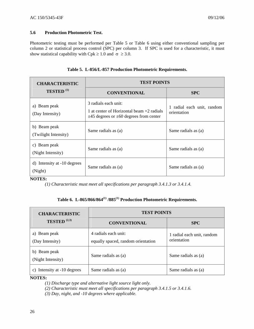
5.6 Production Photometric Test. Photometric testing must be performed per Table 5 or Table 6 using either conventional sampling per column 2 or statistical process control (SPC) per column 3. If SPC is used for a characteristic, it must show statistical capability with Cpk ≥ 1.0 and σ ≥ 3.0.
Table 5. L-856/L-857 Production Photometric Requirements.
TEST POINTS CHARACTERISTIC
TESTED (1)CONVENTIONAL SPC
a) Beam peak
(Day Intensity)
3 radials each unit:
1 at center of Horizontal beam +2 radials ±45 degrees or ±60 degrees from center
1 radial each unit, random orientation
b) Beam peak
(Twilight Intensity) Same radials as (a) Same radials as (a)
c) Beam peak
(Night Intensity) Same radials as (a) Same radials as (a)
d) Intensity at -10 degrees
(Night) Same radials as (a) Same radials as (a)
NOTES: (1) Characteristic must meet all specifications per paragraph 3.4.1.3 or 3.4.1.4.
Table 6. L-865/866/864(1) /885(1) Production Photometric Requirements.
TEST POINTS CHARACTERISTIC
TESTED (2,3)CONVENTIONAL SPC
a) Beam peak
(Day Intensity)
4 radials each unit:
equally spaced, random orientation 1 radial each unit, random orientation
b) Beam peak
(Night Intensity) Same radials as (a) Same radials as (a)
c) Intensity at -10 degrees Same radials as (a) Same radials as (a)
NOTES: (1) Discharge type and alternative light source light only.
(2) Characteristic must meet all specifications per paragraph 3.4.1.5 or 3.4.1.6. (3) Day, night, and -10 degrees where applicable.
26
09/12/06 AC 150/5345-43F
5.7 Production Test Records. Records showing actual test results of all tests required by paragraph 5.5 must be maintained for a period of three years by the manufacturer. These records must be traceable to the units tested and in the case of discharge light units traceable by serial number.
5.8 Production Test Equipment. All measuring and test equipment used in the production of obstruction lighting equipment classified under paragraph 1.2 must have its accuracy and precision maintained by a calibration program with traceability to ISO-10012 Measurement Management Systems – Requirements for Measurement Processes and Measuring Equipment or current industry accreditation criteria. The manufacturer must show that all production photometric testing equipment correlates to the certifying laboratory's equipment to within ±5 percent. Photometric testing must be performed in a properly designed photometric range using a calibrated photometer. For discharge type flashing lights, all photometric measurements must be based on a minimum five flash average.
27

AC 150/5345-43F 09/12/06
Intentionally left blank.
28