Embed Size (px)
Citation preview
Advisory Circular 4
Subject:
SHOULDER HARNESS-
bte: G/4/93 ACNo:=-34 Initiated by: AIR-120 ChQp:
SAFETY BELT INSTALLATIONS
1. PURPOSE. This advisory circular (AC) provides . information and guidance pertinent to an acceptable means,
but not the only means, for installation of shoulder harness and safety belt restraint systems at all seat locations on all previously type certificated aircraft.
2. RELATED FEDERAL AVIATION REGULATIONS (FAR) SECTIONS. Sections 23.5G1, 23.785, and 23.1413 of FAR 23; Sections 27,561, 27.785. and 27.1413 of FAR 27; Sections 29.561, 29.785, and 29.1413 of FAR 29; and Sections 91.107 and 91.203 of FAR 91.
3. BACKGROUND.
a. Basic principles. This AC focuses on basic principles regarding design and installation of combined shoulder harness and safety belt restraint systems which evolve to satisfy the applicable requirements of the FAR. In particular, the following subjects are discussed:
(1) common shoulder harness - safety belt designs; (2) types of hardware available; (3) ramifications of some hardware combinations; (4) effects of the installation geometry; (5) strength characteristics needed to accommodate
an accident loading environment; and (6) structural attachment concepts.
b. Emphasis. Emphasis is placed on performance of a combined shoulder harness and safety belt installation in an accident environment. The accident environment produces dynamic action and reaction forces which peak to some value and decline to zero or reverse direction in m,llllseconds, and most accidents will involve more than one force application cycle. Interaction between the occupant and the seat should be considered, as well as the interaction between the occupant and the shoulder harness-safety belt installation.
AC 21-34
C. Designs to consider. A number of combined shoulder harness and safety belt designs evolved to satisfy the occupant protection requirements of the FAR. Some designs developed for automotive and military aircraft applications may also be applicable in civil aircraft. In conjunction with the shoulder harness and safety belt development, a variety of integral hardware components has evolved to satisfy the coupling, the adjustment, the crewmember movement, and the stowage requirements.
d. Experience. Experience has shown that indiscriminate combinations- and assembly of hardware components may result in an inadequate shoulder harness- safety belt assembly. The same experience has shown that installation geometry and attachment techniques influence the restraint effectiveness of shoulder harness and safety belt installations. In addition, experience has shown that the cabin area surrounding each seat affects the shoulder harness-safety belt combination that is selected.
e. Rationale. Since certain ramifications can occur with the variety of available shoulder harness-safety belt systems and associated hardware, this AC presents information for hardware and system selection, as well as installation concepts, which produce an effective response and a functional installation in the accident environment.
f. Avvroval. An aircraft certification office should assist in evaluating data necessary for the addition of a shoulder harness assembly to an installation previously approved with a safety belt only.
6/4/93
ohn K. McGrath Aircraft Engineering Division Certification Service
ii
6/4/93
CONTENTS
AC 21-34
Page
CONTENTS.................................................iii
LIST OF FIGURES........................ . . . . . . . . . . . . . . . . . . . Vi
CHAPTER 1. GENERAL INFORMATION
1. JUSTIFICATION FOR INSTALLING SHOULDER HARNESSES
i? Experience .................................. ..l Objections .................................. ..l
C. Benefits .................................... ..l
2. SHOULDER HARNESS CONFIGURATIONS
a. Categories ..................................... 1 b. General aspects .............................. ..l C. Example configurations ...................... ...2 d. Civil aircraft shoulder harness ............. ...2
CHAPTER 2. SHOULDER HARNESS INSTALLATION CONSIDERATIONS
3. SHOULDER HARNESS ASSEMBLY DETAILS
a. Webbing ........................................ 5 (1) Webbing width and hardware match ........ ...5 (2) Webbing thickness and hardware match .... ...5 (3) Webbing weave and hardware match ........ ...5 (4) Webbing elasticity and occupant
displacement ............................ ...5 b. Cable ...................................... ...6
(1) Use flexible cable ....................... ..G (2) Avoid sharp bends ........................ ..G (3) Select clevises carefully ................ ..G
c. Energy absorbing devices ................... ...6 d. Buckles ... .............................................................. .
(1) Buckle release ..F (2) Buckle types ............................ ...7
e. Adjustments hardware ....................... ...8 (1) Three-Bar slide adjuster ................ ...8 (2) Tilt lock adjuster........................1 0 (3) Cam lock adjuster.........................1 3
f. Webbing retractors ........................... 13 (1) Emergency locking retractor...............1 3 (2) Automatic locking retractor...............1 4 (3) General retractor precautions.............1 4
g. Attachment end fittings......................1 6 (1) Minimize bending..........................1 G (2) Self alignment............................1 7 (3) Keeper damage ............................. 17
iii
AC 21-34 6/4/93
4. INSTALLATION GEOMETRY Paoe
a.
b.
C.
d. e.
f. 53.
Safety belt.......................................1 7 (1) Shallow angle.................................1 8 (2) Steep angle ................................... 18 (3) Webbing effects...............................1 8 Dual shoulder harness.............................2 0 (1) Optimum harness geometry......................2 0 (2) The negative-G strap..........................2 1 (3) Alternative dual shoulder belts...............2 1 (4) Webbing guides................................2 2 Single diagonal shoulder harness..................2 3 (1) Proper installation ......................... ..2 4 (2) Improper lower attachment ..................... 24 (3) Upper end attachment..........................2 4 (4) Occupant height...............................2 5 Spinal compression ................................ 25 Added structural loads ............................ 27 (1) Excessive angle - excessive loads.............2 7 (2) Excessive angle - excessive motion............2 7 (3) Webbing guides................................2 7 Side facing seats.................................2 7 Installation compliance...........................2 8
5. SHOULDER HARNESS EFFECTS ON SEAT INTEGRITY
E: Need for seat integrity...........................2 8 Lower shoulder harness attachment to seat.........2 8 (1) Existing belt attachments on seat............2 8 (2) Rear seat leg attachments....................2 8
dc: Shoulder harness loading of seat back.............2 9 Non-folding seat backs............................2 9
6. RESTRAINT LOADS
E; Strength criteria.................................2 9 General practice..................................3 0
dc: Restraint load distribution.......................3 1 Qualification of installation.....................3 1
7. STRUCTURAL ATTACHMENTS
E: Preferred method..................................3 1 Scope and intent..................................3 1 (1) Concept 1....................................3 2 (2) Concept 2....................................3 2 (3) Concept 3....................................3 2
iv
6/4/93 AC 21-34
dc: e. f. g-
h. i.
Details of attachments.......................3 2 Bulkhead attachments.........................3 2 Wing carry-through and beltframe attachments.34 Stringer attachments.........................3 5 Floor attachments............................3 5 (1) Reinforcement ........................... 36 (2) Retractor mounting ...................... 36 Attachment to welded tube structure..........3 6 Attachment to wooden structure...............3 7 (1) Nuts and bolts..........................3 7 (2) Bolt head backup........................3 7 (3) Wood splitting..........................3 8 (4) Avoid glued joint ....................... 38
CHAPTER 3. CONCLUSIONS
8. SUMMARY...........................................39
t : Intent of AC..................................39 Shoulder harness-Safety belt checklist........39
C. Special consideration for engineering.....,...40
V
AC 21-34
LIST OF FIGURES
6/4/93
Paqe
1. Typical Aircraft Shoulder Harness Systems..............2
2. Retractors and Manual Length Adjusters.................3
3. Hardware Application Concepts ....................... ...4
4. Lift Lever and Rotary Buckles .......................... 8
5. Three-Bar Slide Webbing Loop ......................... ..g
6. Tilt Lock Adjuster Webbing Loop.......................1 1
7. Cam Lock Adjuster . . . . . . . . . . . . . . . . . . . . . . . . . . . . . . . . . . . . . 12
8. Retractor Webbing Entry - Exit Angle at Guide.........1 5
9. End Fittings .......................................... 17 "
10. Safety Belt Installation Angle........................1 9
11. Occupant Reactions with Dual Shoulder Harness.........2 0
12. Continuous Loop Safety Belt-Shoulder Harness..........2 1
13. Single Diagonal Shoulder Harness Geometry.............23
14. Shoulder Harness Attachment Elevation.................26
15. Possible Bulkhead Attachment and Reinforcement........33
16. Possible Wing Carry-Through or Beltframe Attachment and Reinforcement I.................................... 34
17. Dual Shoulder Harness Attachment to Floor.............35
18. Attachment and Reinforcement of Welded Tube Structure.37
vi
6/4/93
CHAPTER 1. GENERAL INFORMATION
AC! 21-34
1. JUSTIFICATION FOR INSTALLING SHOULDER HARNESSES
a. Experience. Accident experience has provided substantial evidence that use of a shoulder harness in conjunction with a safety belt can reduce serious injuries to the head, neck, and upper torso of aircraft occupants and has the potential to reduce fatalities of occupants involved in an otherwise survivable accident.
b. Objections. Host aircraft occupants readily accept use of a safety belt for security during turbulence, acrobatic maneuvers, or agricultural flying. A shoulder harness, however, is generally associated with the relatively rare occurrence of an accident. It is often heard that a shoulder harness is cumbersome, unwieldy, hot, and uncomfortable to use. Such objections for not installing and using a shoulder harness should be dispelled in view of the benefits gained from a correctly designed, installed, and used shoulder harness-safety belt system.
Benefits. Shoulder harness-safety belt systems prevzht serious head, neck, and upper torso injuries in what may be relatively minor accidents in terms of aircraft damage, and they can prevent irreversible or fatal injuries in more severe accidents. Therefore, the major benefits of shoulder harnesses occur in an accident environment, but they can be of no benefit if they are not available for use in an accident.
2. SHOULDER HARNESS CONFIGURATIONS.
a. Categories. Shoulder harness assemblies are categorized as single shoulder belt and dual shoulder belt. The single shoulder belt configuration is normally arranged diagonally across the occupant’s upper torso and is often referred to as a 3-point system. The dual shoulder belt is a symmetrical arrangement of the two belts with one belt passing over each shoulder of the occupant, and is frequency referred to as a I-point system, or a 5-point system if a negative-G strap is used. These assembly configurations, as well as others, may be acceptable with proper design and evaluation.
b. General aswcts. The aspects to consider in the selection and installation of a shoulder harness-safety belt assembly are the security of the hardware, the containment and strength of the assembly relative to the installation geometry, the ease and extent of belt length adjustment, the means for rapid release, and the comfort of the wearer.
AC 21-34 6/4/93
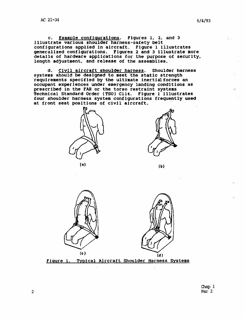
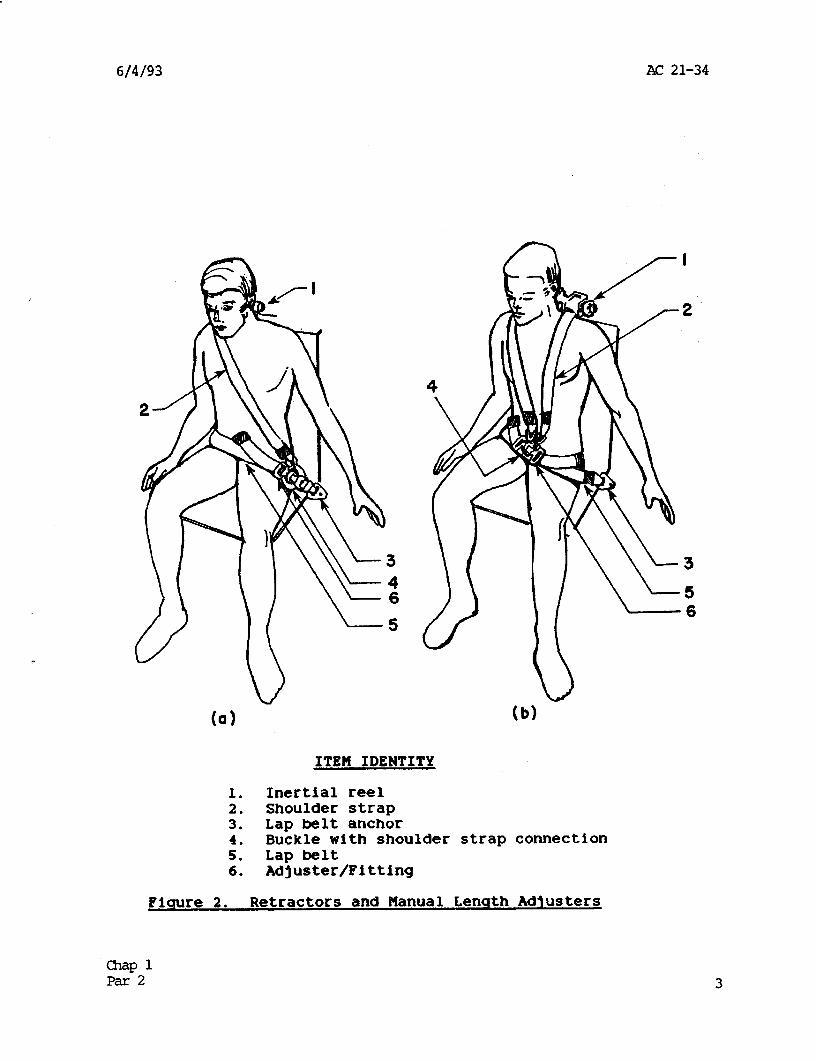
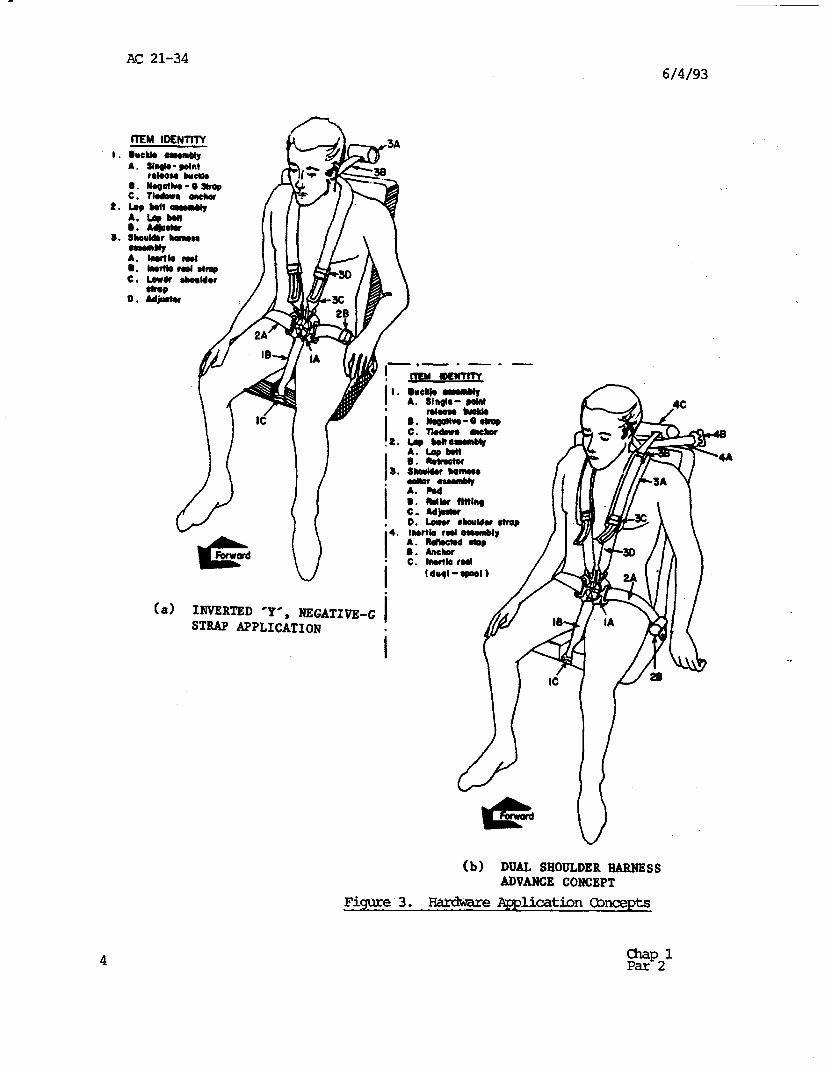
Example confisurations. Figures 1, 2, and 3 illuskate various shoulder harness-safety belt configurations applied in aircraft. Figure 1 illustrates generalized configurations. Figures 2 and 3 illustrate more details of hardware applications for the purpose of security, length adjustment, and release of the assemblies.
d. Civil aircraft shoulder harness. Shoulder harness systems should be designed to meet the static strength requirements specified by the ultimate inertialforces an occupant experiences under emergency landing conditions as prescribed in the FAR or the torso restraint systems Technical Standard Order (TSO) C114. Figure 1 illustrates four shoulder harness system configurations frequently used at front seat positions of civil aircraft.
Fiqure 1. Typical Aircraft Shoulder Harness Systems
2 -Pl Par 2
6/4/93 AC 21-34
(a)
3
5 6 (b)
ITEM IDENTITY
1. Inertial reel 2. Shoulder strap 3. Lap belt anchor 4. Buckle with shoulder strap connection 5. Lap belt 6. Adjuster/Fitting
Picmre 2. Retractors and Manual Lenqth Adjusters
-P 1 Par2
AC 21-34 6/4/93
A. Sh@o-polnl rob008 buchb
6. Nb6oOlw-63rop c. tbdeun onchar
2. Lopbolt-bly A. L9pb.n 6. Ad@rkr
3. sboulhr hamn -w A. bulb crl
,-.- -
A. singlo- @olnl nbomohlEkb
.
I c- Adjwbr 0. bwu rhouldurtrop l 4. lnwtb rnloaanbly
I A. nmubd mm I . (a> INVERTED *Y*, NEGATIVE-G
STRAP APPLICATION I .
I
(b) DUAL SHOULDER HARNESS
~V&JCE CONCEPT
4
Figure 3. Hardvare~licationCWcepts
zzp21
6/4/93 AC 21-34
CHARTER 2. SHOULDER HARNESS INSTALLATION CONSIDERATIONS
3. 'SHOULDER HARNESS ASSEMBLY DETAILS.
a. Webbinq. Webbing is one element common to all shoulder harness-safety belt assemblies. Webbing should be made of synthetic materials to avoid deterioration by mildew and water exposure. Other webbing characteristics to consider are the width, thickness, weave, and elasticity.
(1) Webbinq width and hardware match. Hardware, such as length adjusters and end fittings, should be appropriate for the webbing width to preclude accelerated webbing wear and cutting of the webbing under restraint loads. Technical Standard Order (TSO) C114, Torso Restraint Systems, permits a minimum webbing width of 1.8 inches. The majority of shoulder harness-safety belt systems designed for civil aircraft use a nominal 2.0 inch wide webbing. Webbing widths of 2.25 to 3.0 inches and associated hardware are also available for special purpose applications. For the reasons previously stated, it is poor practice to adapt hardware designed for one width to another width of webbing.
(2) Webbinq thickness and hardware match. It is important to match hardware to the webbing thickness. Nominal webbing thicknesses of 0.04 and 0.06 inches are common in civil aircraft shoulder harness-safety belt assemblies. Thicker webbing is available for special purpose applications. Thickness contributes to maintaining more webbing contact with occupants under loads. Retractors and manual length adjusters are sensitive to webbing thickness.
(3) Webbinq weave and hardware match. Webbing weave and the design of length adjustment hardware should be matched for proper functioning of the adjuster. A herringbone weave is used for most new webbing. Adjustment hardware designed for the coarse perpendicular warp and fill type webbing may permit excessive slippage of the herringbone weave webbing under loads.
(4) Webbinq elasticity and occupant displacement. Webbing commonly used in shoulder harness-safety belt designs is an elastic material. Nylon is the most common material, and with the herringbone weave the elasticity (stretch) of the 2.0-inch wide webbing is generally between 17 and 20 percent under a tensile force of 2500 pounds. Dacron webbing is also available. The 2.0-inch wide dacron webbing with the herringbone weave exhibits an elasticity of about 8 percent under a tensile force of 2500 pounds. Consequently, the length of webbing in shoulder belts should be evaluated relative to the webbing elasticity and the permitted
-3P2 Par3 5
AC 21-34 6/4/93
displacement of an occupant under loads. If limited space is available in the aircraft for displacement of an occupant under loads, substantial elongation of the webbing should not be possible.
b. Cable. The use of steel aircraft cable offers a means of reducing the amount of occupant displacement resulting from webbing stretch-. Cable also offers a means for extending belts to a suitable attachment point. Precautions regarding the use of a steel cable are:
(1) Use flexible cable. Flexible cable is needed to prevent fatigue failure of the cable strands through flexing during normal use of the shoulder harness or safety belt. Cable intended for guy wire purposes is normally unsuitable.
(2) Avoid sharp bends. Avoid situations where the cable bends over sharp edges of structure during normal use. Running the cable through structural members without a grommet or pulley guide accelerates local work hardening failure of the cable strands. A bend radius of at least 4 times the cable diameter should be provided if bending is unavoidable.
(3) Select clevises carefully. Selection of any cable clevis needs careful attention. Control cable clevises normally have insufficient strength. Cable characteristics and cable terminal techniques are provided in AC 43.13-lA, Acceptable Methods, Techniques, and Practices - Aircraft Inspections and Repairs.
C. Energy absorbinq devices. The use of energy absorbing devices in the webbing of the shoulder harness or safety belt is not recommended primarily because of the increased potential for secondary occupant impacts. Energy absorbing devices, also known as load limiting devices, are best incorporated in the airframe structure or aircraft seat. Secondary impact and insufficient torso retention should be expected when energy absorbing devices are used in webbing, and webbing elongation should be limited.
d. Buckles. Buckles are the basic means for securing the various segments of a shoulder harness-safety belt system around an occupant while also providing the means of release of the system. The equipment requirements for safety belts and shoulder harnesses in the FAR for a metal-to-metal coupling provide improved security and reliability over any method of coupling which relies on clamping of the webbing. Although the load bearing components of the buckle latch and
6 a-&P32
6/4/93 AC 21-34
the load path to the webbing are metal, a nonmetallic cover on the buckle for decoration, corrosion protection, etc., is an acceptable practice.
(1) Buckle release. For security, design of the release mechanism should minimize the possibility for inadvertent release by the occupant and premature release by inertial forces acting on the mechanism in an accident. For escape after an accident, buckle release characteristics should permit release with one finger.
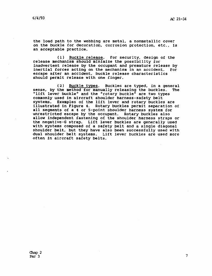
(2) Buckle tvnes. Buckles are typed, in a general sense, by the method for manually releasing the buckles. The “lift lever buckle” and the “rotary buckle” are two types commonly used in aircraft shoulder harness-safety belt systems. Examples of the lift lever and rotary buckles are illustrated in Figure 4. Rotary buckles permit separation of all segments of a 4 or 5-point shoulder harness system for unrestricted escape by the occupant. Rotary buckles also allow independent fastening of the shoulder harness straps or the negative-G strap. Lift lever buckles are generally used with systems composed of a safety belt and a single diagonal shoulder belt, but they have also been successfully used with dual shoulder belt systems. Lift lever buckles are used more often in aircraft safety belts.
AC 21-34 6/4/93
Fiqure 4. Lift Lever and Rotary Buckles
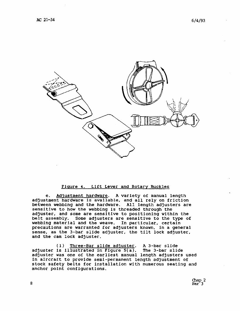
e. Adjustment hardware. A variety of manual length adjustment hardware is available, and all rely on friction between webbing and the hardware. All length adjusters are sensitive to how the webbing is threaded through the adjuster, and some are sensitive to positioning within the belt assembly. Some adjusters are sensitive to the type of webbing material and the weave. In particular, certain precautions are warranted for adjusters known, in a general sense, as the 3-bar slide adjuster, the tilt lock adjuster, and the cam lock adjuster.
(1) Three-Bar slide adjuster. A 3-bar slide adjuster is illustrated in Figure 5(a). The 3-bar slide adjuster was one of the earliest manual length adjusters used in aircraft to provide semi-permanent length adjustment of stock safety belts for installation with numerous seating and anchor point configurations.
8 char,2 par- 3
AC 21-34 6/4/.93
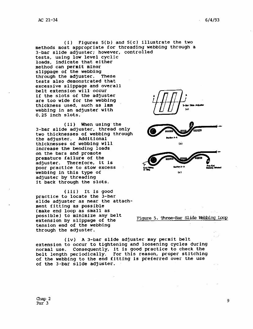
(i) Figures 5(b) and 5(c) illustrate the two methods most appropriate for threading webbing through a 3-bar slide adjuster; however, controlled tests, using low level cyclic loads, indicate that either method can permit minor slippage of the webbing through the adjuster. These tests also demonstrated that excessive slippage and overall belt extension will occur if the slots of the adjuster are too wide for the webbing thickness used, such as lmm webbing in an adjuster with 0.25 inch slots.
(ii) When using the 3-bar slide adjuster, thread only two thicknesses of webbing through the adjuster. Additional thicknesses of webbing will increase the bending loads on the bars and promote premature failure of the adjuster. Therefore, it is poor practice to stow excess webbing in this type of adjuster by threading it back through the slots.
(iii) It is good practice to locate the S-bar slide adjuster as near the attach- ment fitting as possible (make end loop as small as possible) to minimize any belt extension by slippage of the tension end of the webbing through the adjuster.
Figure 5. Three-Bar Slide Ebbing Lmp
(iv) A 3-bar slide adjuster may permit belt extension to occur to tightening and loosening cycles during normal use. Consequently, it is good practice to check the belt length periodically. For this reason, proper stitching of the webbing to the end fitting is preferred over the use of the 3-bar slide adjuster.
&P2 Par 3 9
AC 21-34 6/4/93
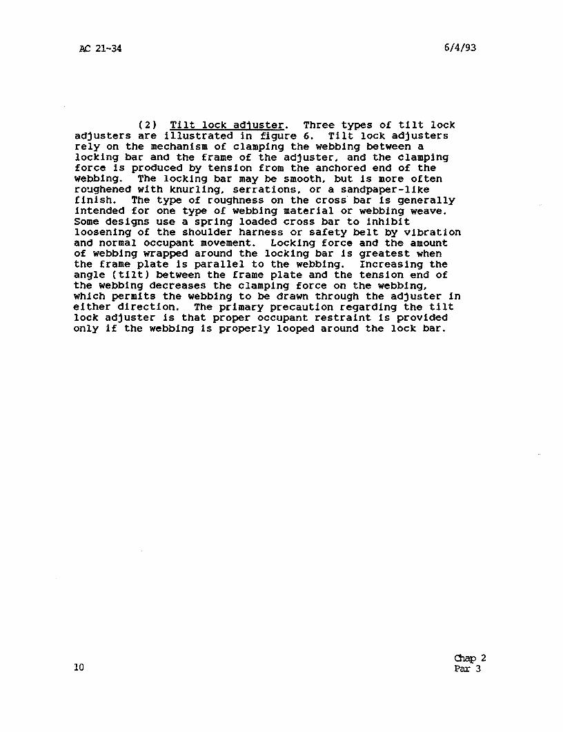
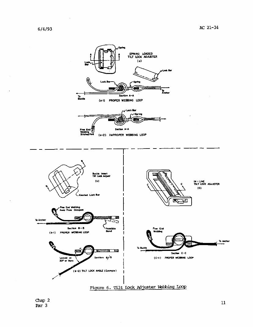
(2) Tilt lock adjuster. Three types of tilt lock adjusters are illustrated in figure 6. Tilt lock adjusters rely on the mechanism of clamping the webbing between a locking bar and the frame of the adjuster, and the clamping force is produced by tension from the anchored end of the webbing. The locking bar may be smooth, but is more often roughened with knurllng, serratlons, or a sandpaper-like finish. The type of roughness on the cross'bar is generally intended for one type of webbing material or webbing weave. Some designs use a spring loaded cross bar to inhibit loosening of the shoulder harness or safety belt by vibration and normal occupant movement. Locking force and the amount of webbing wrapped around the locking bar is greatest when the frame plate is parallel to the webbing. Increasing the angle (tilt) between the frame plate and the tension end of the webbing decreases the clamping force on the webbing, which permits the webbing to be drawn through the adjuster in either direction. The primary precaution regarding the tilt lock adjuster is that proper occupant restraint is provided only if the webbing is properly looped around the lock bar.
10 QlaP2 Par 3
6/4/93 AC 21-34
SPRING -0 1ll.T IBCK AOJBlER
Rwklo (a-1) PROPER WEBBING LOOP
Sri-Fdd (o-2) IMPROPER WEBBING LC@
v--e - -e -p---w--
(b)
soe1lon B-R \ Fossibl~
(b-1) PROPER WEBeING ue Romd
b-2) TILT LOCK PHilE (tamPI*)
i
I
IN-UN2 nu LOCK
(Cl
AOJUSTER
Qlap2 Par 3 11
AC 21-34 6/4/93
(i) The term “tilt lock” refers to the angle at which the webbing is locked. figure 6(b-2) illustrates this aspect. To maintain locking with the adjuster bearing on a curved surf ace, such as an occupant, a tilt lock adjuster should lock with a “tilt” angle of 30 degrees or more between the adjuster plate and webbing, with a webbing tension force of 20 pounds, and remain locked for all smaller angles.
(ii) The adjuster illustrated in Figure 6(a) is sensitive to the manner in which the webbing is looped on the lock bar. As illustrated in Figure 6(a-1). the webbing should be looped around the lock bar in the manner .which causes belt tension to draw on the flat side of the lock bar and applies shear loads to the thinner ears of the lock bar. The shear,reaction in the thinner ears is low. An improper webbing loop appears, and provides adjustment, about the same as a proper webbing loop on this type of adjuster, but the strength of the assembly is substantially reduced. Therefore, shoulder harness and safety belt systems using this type of adjuster warrant close examination of the webbing loop on the lock bar of the adjuster.
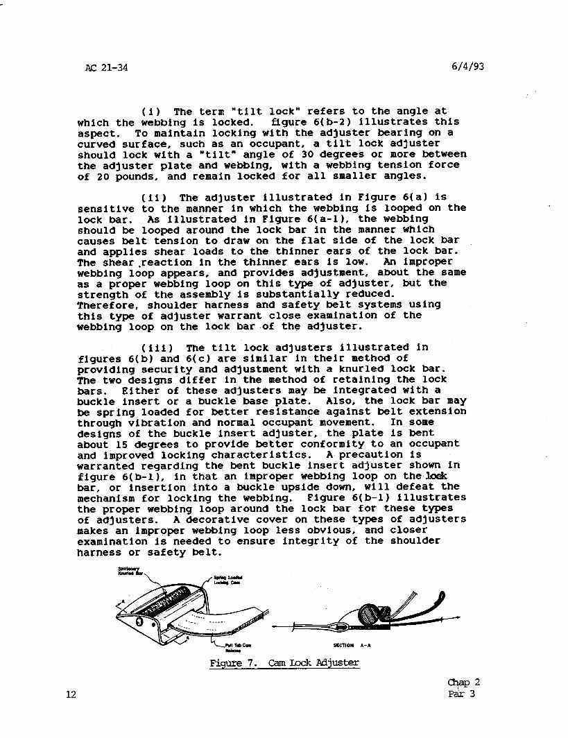
(iii) The tilt lock adjusters illustrated in .figures 6(b) and 6(c) are similar in their method of providing security and adjustment with a knurled lock bar. The two designs differ in the method of retaining the lock bars. Either of these adjusters may be integrated with a buckle insert or a buckle base plate. Also, the lock bar may be spring loaded for better resistance against belt extension through vibration and normal occupant movement. In some designs of the buckle insert adjuster, the plate is bent about 15 degrees to provide better conformity to an occupant and improved locking characteristics. A precaution is warranted regarding the bent buckle insert adjuster shown in figure 6( b-l 1, in that an improper webbing loop on thelo& bar, or insertion into a buckle upside down, will defeat the mechanism for locking the webbing. Figure 6( b-l) illustrates the proper webbing loop around the lock bar for these types of adjusters. A decorative cover on these types of adjusters makes an improper webbing loop less obvious, and closer examination is needed to ensure integrity of the shoulder harness or safety belt.
Figure 7. CamLockAdjUSter
12 olap2 P&z 3
6/14/93 AC 21-34
(3) Cam lock adjuster. The cam lock webbing adjuster illustrated in figure 7 is common in military shoulder harness-safety belt systems. The cam is generally spring loaded for sufficient clamping of the webbing to prevent slippage of the webbing by vibration and normal occupant movement. Frequent adjustment with the cam lock adjuster may produce more rapid deterioration (fraying) of conventional webbing than some of the other types of adjusters. Other cam lock adjuster designs may be available. The principal precaution is to ensure that the webbing is looped through the adjuster so that restraint loads tend to increase the clamping force of the cam.
f. Webbins retractors. Webbing retractors are frequently incorporated in shoulder harness and safety belt systems to satisfy the crewmember movement and/or webbing stowage requirements of the FAR. They can also enhance comfort and ease of length adjustment, which encourages use of the shoulder harness as well as the safety belt. Retractors are categorized by the point in time when they lock to provide occupant restraint. These categories are the emergency locking retractor and the automatic locking retractor. It is difficult to distinguish between the two categories by,a cursory visual examination.
(1) Emergency lockina retractor. Emergency locking retractors are frequently called "inertia reels" because their functional mechanism is characterized by the feature of providing positive restraint only when significant inertial forces are experienced. Three types of emergency locking retractors which may be encountered are as follows:
(i) One type of "inertia reel" appropriate for aircraft use is known as the webbing sensitive reel. It produces locking by a change in the rate (acceleration) of webbing withdrawal from the retractor, which is functional for occupant accelerations in any direction producing extension of the webbing. A locking acceleration of 0.75 to 1.5 G's is satisfactory.
(ii) A second type of "inertia reel", which is common in automotive applications, is known as the vehicle sensitive reel. It produces locking by a physical acceleration of the retractor itself, or it may be locked by a remote sensor on the vehicle.
chap2 Par 3 13
AC 21-34 6/4/93
(iii) A third type of "inertia reel" has a dual locking mechanism which combines the favorable features of both the webbing sensitive reel and the vehicle sensitive reel. This type of reel is quite suitable for aircraft applications.
NOTE: A precaution is that emergency locking retractors are for use on shoulder belts only. Their use on safety belts prevents proper tightening of the safety belt on the pelvis and promotes occupant submarining under the belt in a dynamic loading environment, because the design inherently permits a certain amount of webbing extension before it locks. Also, if turbulence occurs which does not produce accelerations large enough to provide locking, no restraint is provided.
(2) Automatic lockinq retractor. Automatic locking retractors provide automatic retraction of webbing for length adjustment and stowage of webbing. Their functional mechanism is characterized by the feature of permitting free webbing extension for coupling of the safety belt, but the moment any webbing is automatically retracted, the locking mechanism locks to prevent further webbing extension. However, the designs usually prevent locking within about the first 25 percent (6 to 10 inches) of webbing extended from the retractor. Therefore, a precaution for use of the automatic locking retractors is to ensure that the mounting location for these retractors will actually produce locking (more than 25 percent webbing extension) when the occupant has the safety belt coupled around him. When automatic locking retractors are incorporated at both attachments of the safety belt, buckle positioning by the user becomes important for proper function of the retractors under emergency conditions.
(3) General retractor Drecautions. Experience has shown that certain features of retractors, in general, are worthy of mention to ensure proper function:
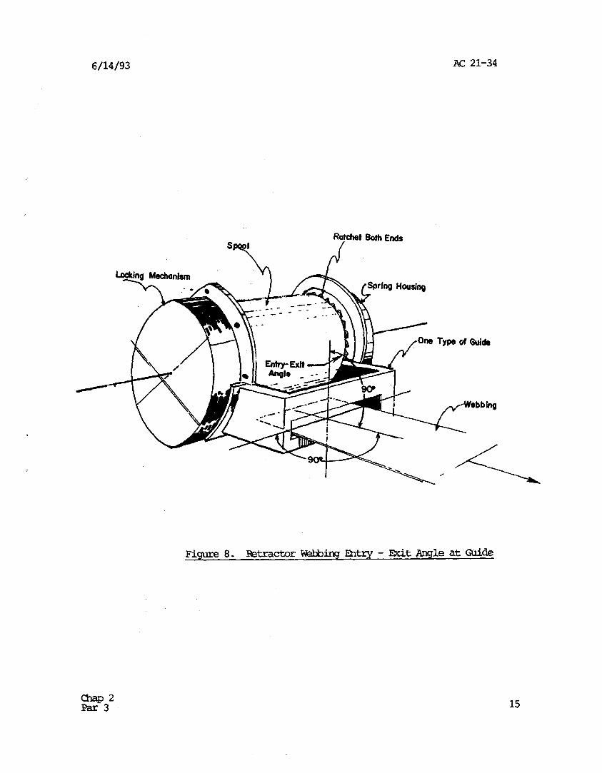
(i) A properly designed retractor incorporates a webbing guide to prevent folded webbing from wrapping onto the spool. The guide also serves to prevent webbing from wrapping onto an exposed locking ratchet. Some ratchets are sharp enough to penetrate and cut the webbing. The guide may be an integral part of the retractor, or it may be provided by the retractor housing. Alternatively, straightening and alignment of the webbing to the retractor spool may be provided by a remote pull-through guide. Folded webbing wrapped on the spool may promote binding and disuse or malfunction of the shoulder harness or safety belt.
14 z32
6/14/93 AC 21-34
Figure 8. RztractorWebbingIQkry-Exit &ngleatWde
15
AC 21-34 6/4/93
(ii) Proper mounting of retractors provides a straight line entry and exit of webbing through the integral or local webbing guide, as illustrated in Figure 8. The straight line entry and exit minimizes abrasive wear on the webbing, and more importantly, it minimizes frictional drag between the webbing and guide, which could inhibit functioning of the retractor. A remote webbing guide may be warranted when seat backs or other structures prevent straight line entry and exit of the webbing at the local webbing guide.
(iii) Methods of attaching retractors to the airframe or seat are generally intended to load attachment fasteners in shear. Sufficient fastener holes are normally available in the retractor frame or base, and fasteners of sufficient strength should be used which fill the available holes. Attachment configurations resulting in bending or tension loads on the fasteners under accident conditions warrant scrutiny for strength of the fasteners and the frame or base of the retractor.
(iv) Retractors should be mounted to minimize exposure to dirt and abuse.
(v) Too much webbing on the retractor spool can prevent the locking device from engaging the ratchet. For this reason, the locking function should be checked with the belts extended and coupled around a small occupant.
(vi) Check the ability of the retractor installation for sufficient retraction force to overcome webbing drag on the seat or through guides and other structures, to ensure proper retrieval of webbing slack during operation of the aircraft. The webbing retrieval feature may also improve occupant restraint in a multiple impact accident.
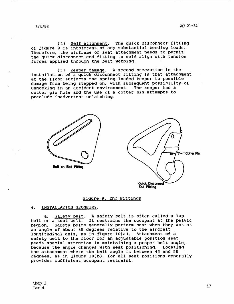
g- Attachment end fittinqs. A variety of end fittings may be found in service, but they are generally classed as ‘*bolt-on fittings” or “quick disconnect fittings” as illustrated in figure 9.
( 1) Minimize bendinq. The principal precaution for installing the fitting is to minimize bending stress in the fitting. The fittings of figure 9 are designed to load the attaching bolt in shear. When the application is likely to load the attaching bolt in bending or tension, a specially designed fitting is warranted, which is preformed to align the fitting with the principal forces from the belt.
16 E?32
6/4/93 AC 21-34
(2) Self aliqnment. The quick disconnect fitting of :figure 9 is intolerant of any substantial bending loads. Therefore, the airframe or seat attachment needs to permit the quick disconnect end fitting to self align with tension forces applied through the belt webbing.
(3) Keener damage. A second precaution in the installation of a quick disconnect fitting is that attachment at the floor subjects the spring-loaded keeper to possible damage from being stepped on, with subsequent possibility of unhooking in an accident environment. The keeper has a cotter pin hole and the use of a cotter pin attempts to preclude inadvertent unlatching.
Bolt on End Fflthg
fJh
Figure 9. End Fittings
4. INSTALLATION GEOMETRY.
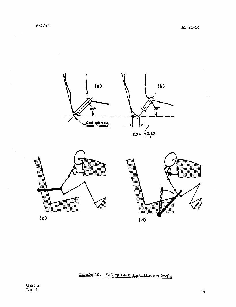
a. Safety belt. A safety belt is often called a lap belt or a seat belt. It restrains the occupant at the pelvic region. Safety belts generally perform best when they act at an angle of about 45 degrees relative to the aircraft longitudinal axis, as in figure 10(a). Attachment of a safety belt to the floor for an adjustable position seat needs special attention in maintaining a proper belt angle, because the angle changes with seat positioning. Locating the attachment where the belt angle is between 45 and 55 degrees, as in figure 10(b), for all seat positions generally provides sufficient occupant restraint.
-P 2 Par4 17
AC 21-34 6/4/93
(1) Shallow anale. If the safety belt is installed so that it acts along a shallow angle, as in figure 10(c), it is likely to slip off the pelvis of the occupant, and apply loads to the abdomen, with a likelihood of injury to internal organs. In addition, the shallow belt angle is prone to produce "anterior wedge fracture of the lumbar vertebra" as the upper torso flexes over the belt and is compressed under accident inertial forces. Muscular resistance to the upper torso flexure is unlikely for even the strongest individuals at decelerations above 3 or 4 G's.
(2) Steen angle. If the safety belt is installed at too steep an angle, as in figure 10(d), it will be ineffective in resisting forward movement of the occupant. Since the belt can carry tension loads only, the occupant will move forward until the belt geometry is reoriented to an angle which generates enough tension in the belt to.resist further forward movement. An extreme safety belt angle like that of figure 10(d) permits knee impact with the instrument panel resulting in knee or femur injury, or forward movement to the extent that the occupant slips off the front edge of the seat allowing the belt angle to become shallow with all the injury potential mentioned above.
(3) Webbins effects. Webbing elasticity, previously discussed in subparagraph 3a(4), permits additional occupant movement. Therefore, prudent selection of the safety belt attachment point will also consider the length of webbing involved and the relative effects of webbing elasticity.
18
6/4/93 AC 21-34
k 450 -.-.- -mm-,
/
\ S&t roformcr point (typical)
W
Figure 10. safety Belt Installation Angle
19
AC 21-34 6/4/93
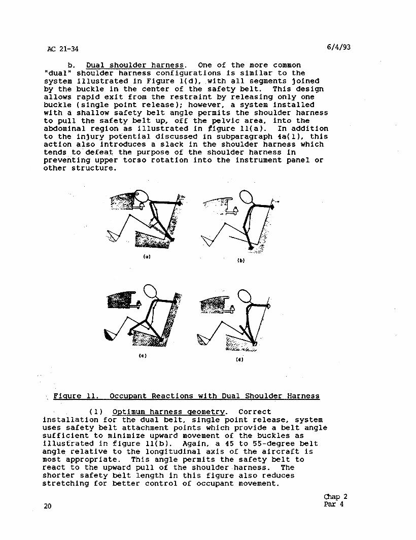
b. Dual shoulder harness. One of the more common " dua 1 " shoulder harness configurations is similar to the system illustrated in Figure l(d), with all segments joined by the buckle in the center of the safety belt. This design allows rapid exit from the restraint by releasing only one buckle (single point release); however, a system installed with a shallow safety belt angle permits the shoulder harness to pull the safety belt up, off the pelvic area; into the abdominal region as illustrated in gigure 11(a). In addition to the injury potential discussed in subparagraph 4a(l), this action also introduces a slack in the shoulder harness which tends to‘defeat the purpose of the shoulder harness in
into the instrument panel or preventing upper torso rotation other structure.
(b)
Y Fiqure 11. Occupant Reactions with Dual Shoulder Harness
(1) Optimum harness creometry. Correct installation for the dual belt, single point release, system uses safety belt attachment points which provide a belt-angle sufficient to minimize upward movement of the buckles as illustrated in figure 11(b). Again, a 45 to 55-degree belt angle relative to the longitudinal axis of the aircraft is most appropriate. This angle permits the safety belt to react to the upward pull of the shoulder harness. The shorter safety belt length in this figure also reduces stretching for better control of occupant movement.
20 Ep4'
6/4/93 AC 21-34
(2) The negative-G strap. Another method of reducing upward movement of the dual belt, single point release, system uses the "negative-G strap" (often called a crotch strap) as illustrated in figure 11(c). A properly ' installed negative-G strap is attached at one end of the buckle, and at the other end to the front edge of the seat or' " " to the airframe under the seat. The length is such that no .] ' slack exists in the strap when the lap belt is properly positioned in the pelvic region. In this position, the negative-G strap acts to resist the upward pull of the shoulder harness. This method has proven very effective and has been adopted for many commercial and acrobatic pilot.crew seats. .
(3) Alternative dual shoulder belts. An alternative dual shoulder harness system is illustrated in figure 11(d). This system attaches the shoulder belts in the same general area as the safety belt attachments. Special evaluation of the attachment is necessary when attaching the lower end of this type of dual shoulder harness to existing safety belt attachments, because of the change in direction and magnitude of the ultimate forces applied to the fittings in an accident. This system avoids any upward pull at the buckle from the shoulder harness, and the safety belt is more likely to remain in the pelvic region during an accident; however, releasing the buckle does not release the shoulder harness. Use of emergency locking retractors on the upper end of the shoulder harness will simplify length adjustment and exit from this type of dual shoulder harness.
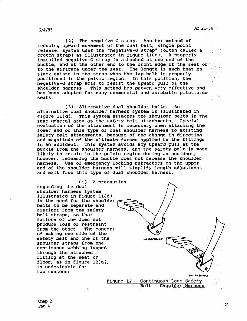
(1) A precaution regarding the dual shoulder harness system illustrated in Figure 11(d) is the need for the shoulder belts to be separate and distinct from the safety belt straps, so that failure of one does not produce loss of restraint from the other. The concept of making one side of the safety belt and one of the shoulder straps from one continuous webbing looped through the attached fitting at the seat or floor, as in Figure 12(a), is undesirable for two reasons: 0) AcemTuLE
Fiqure 12. Continuous Loop Safety Belt - Shoulder Harness
chap 2 Par 4 21
AC 21-34 6/4/93
(A) Failure of either the safety belt portion or the shoulder belt portion releases. the entire restraint system; and
(8) Since such a continuous loop system will apply equal load to the body in all belt segments, attempts to tighten the safety belt will place uncomfortable loads on the shoulder/clavicles. This will encourage a loosely worn restraint and creates a situation for submarining. Structural deformation of the cabin during an accident can also cause slack in the safety belt with the same effect; however, a method 06 extending the lower end of the. shoulder strap through a slot in the safety belt attachment fitting, and permanently attaching (sewing) it to the safety belt near the buckle, as in Figure 12(b), is acceptable, and will provide slack in the shoulder harness for exiting when the buckle is released. Special evaluation of the buckle and attachment fitting strength is necessary for this type of installation.
(ii) A second precauti.on regarding the shoulder harness system of Figure 11(d) is the need to use the "Inverted Y" type shoulder harness, or to have each shoulder belt attached to the seat or a bulkhead directly behind the occupant's head (See figure 1). The union of the "Y" type shoulder straps needs to be within 3 to 6 inches behind the occupant's neck to retain the shoulder belts in the proper position on the occupant's shoulders. Too, large a separation may allow upper torso slippage through the straps by a narrow-shouldered person.
(4) Webbing guides. Dual shoulder belts with lengths of webbing extending more than 12 inches behind the shoulders need webbing guides positioned to hold the belts in the approximate midpoint of the occupant's shoulder. The guides should pemit no more than l/2 inch of lateral movement of the webbing. Without the guides, occupant movement can position the shoulder belts at the outside of one or both shoulders, such that inertial forces in an accident cause the shoulder(s) to slip from the shoulder restraint with loss of upper torso protection and possible violent twisting injury of the spinal column.
22 Ep42
6/4/93 A(= 21-34
(a) (b)
W
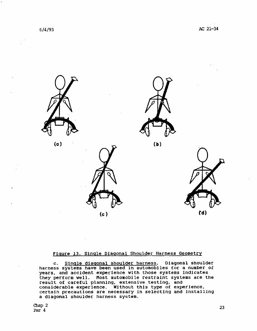
Fisure 13. Sinqle Diagonal Shoulder Harness Geometry
C. Sinqle diagonal shoulder harness. Diagonal shoulder harness systems have been used in automobiles for a number of years, and accident experience with those systems indicates they perform well. Host automobile restraint systems are the result of careful planning, extensive testing, and considerable experience. Without this type of experience, certain precautions are necessary in selecting and installing a diagonal shoulder harness system.
z42 23
2X 21-34 6/4/93
(1) Proper installation. A proper installation geometry for the diagonal shoulder harness positions the shoulder belt so that it passes over the midpoint of the shoulder, with the lower end fastened well to the side of the occupant's hip as illustrated in Figure 13(a). Attachment of the lower end of the shoulder harness to the sa.fety belt is an acceptable convention, as long as the proper geometry-is maintained, but caution is needed to ensure that the portion of webbing common to both the shoulder belt and the safety belt has sufficient.strength to sustain restraint loads from both segments. Alternatively, the lower end of the shoulder belt may be attached separately with an emergency locking retractor incorporated in the upper end for length adjustment and exit purposes. In either case, the geometric arrangement of the shoulder belt is important in performing the upper torso restraint function.
(2) Improper lower attachment. Figure 13(b) illustrates an improper attachment of the diagonal shoulder belt to a buckle situated near'the center of the pelvic region. The shoulder belt is no longer diagonal across the occupant's body. The shoulder belt passes low and to the side of the center of mass of the upper torso, so that in a severe accident the torso may twist around the belt and even slide out of the belt.
(3) Upper end attachment. In selecting the upper end attachment point for a diagonal shoulder harness, precautions should be taken to avoid critical problems associated with variations in occupant size. Figure 13(c) illustrates the situation in which the shoulder belt bears against the neck or the side of the head of a short occupant. A similar situation is expected, even for an average size occupant, when the upper attachment point is located too near the vertical centerline plane of the seat. This installation geometry is aggravating and generally discourages use of the shoulder harness. An excessive elevation angle on the shoulder belt may have the same effect (Reference figure 14(a)). Figure 13(d) illustrates how the shoulder belt may tend to fall off the shoulder of a tall occupant, or when the upper attachment point is too far outboard or too low with respect to the midpoint of the occupant's shoulder. This geometry is also aggravating and discourages use of the shoulder harness, When the shoulder belt falls below the center of mass of the upper torso, the body may rotate around the shoulder belt, and a severe accident may produce enough body motion to allow the head to contact the instrument panel.
24 S4"
6/4/93 AC 21-34
(4) Occupant heisht. General anthropomorphic data indicate that an adult occupant sitting height to the midshoulder can range from about 21.5 inches for a small female to 27.5 inches for a large male. A midshoulder height of 25 inches approximates a large female and an average male and is an appropriate starting point for selecting shoulder harness attachment points.
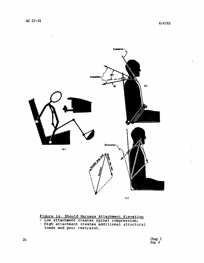
d. Spinal compression. Additionally, for both dual and single diagonal shoulder harnesses, compression of the spinal column by the shoulder belts(s) should be avoided. Spinal compression can generally be avoided if the upper attachment point of the shoulder harness is selected to provide a geometry where the trailing length behind the occupant does not fall below an angle of 5 degrees below the longitudinal tangent to the occupant’s shoulder, as illustrated in Figure 14(a). Spinal compression is likely to occur when the upper end of the shoulder belt is mounted an excessive amount below the occupant’s shoulder level. With the configuration illustrated in figure 14(b), the shoulder belt pulls down and back on the torso as it resists the forward motion of the occupant. The resultant restraint force, as depicted in figure 14(c), will place the spinal column in compression, and will add to the stresses in the column caused by the vertical component of the impact deceleration force.
25
AC 21-34 6/4/93
(b)
Fiqure 14. Should Harness Attachment Elevation - Low attachment creates spinal compression; - High attachment creates additional structural
loads and poor restraint.
26 Ep4'
6/4/93 AC 21-34
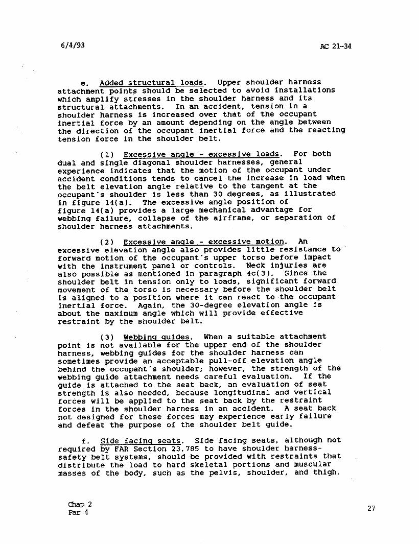
e. Added structural loads. Upper shoulder harness attachment points should be selected to avoid installations which amplify stresses in the shoulder harness and its structural attachments. In an accident, tension in a shoulder harness is increased over that of the occupant inertial force by an amount depending on the angle between the direction of the occupant inertial force and the reacting tension force in the shoulder belt.
(1) Excessive anqle - excessive loads. For both dual and single diagonal shoulder harnesses, general experience indicates that the motion of the occupant under accident conditions tends to cancel the increase in load when the belt elevation angle relative to the tangent at the occupant's shoulder is less than 30 degrees, as illustrated in figure 14(a). The excessive angle position of figure 14(a) provides a large mechanical advantage for webbing failure, collapse of the airframe, or separation of shoulder harness attachments.
(2) Excessive anqle - excessive motion. An excessive elevation angle also provides little resistance to forward motion of the occupant's upper torso before impact with the instrument panel or controls. Neck injuries are also possible as mentioned in paragraph 4c(3). Since the shoulder belt in tension only to loads, significant forward movement of the torso is necessary before the shoulder belt is aligned to a position where it can react to the occupant inertial force. Again, the 30-degree elevation angle is about the maximum angle which will provide effective restraint by the shoulder belt.
(3) Webbinq quides. When a suitable attachment point is not available for the upper end of the shoulder harness, webbing guides for the shoulder harness can sometimes provide an acceptable pull-off elevation angle behind the occupant's shoulder; however, the strength of the webbing guide attachment needs careful evaluation. If the guide is attached to the seat back, an evaluation of seat strength is also needed, because longitudinal and vertical forces will be applied to the seat back by the restraint forces in the shoulder harness in an accident. A seat back not designed for these forces may experience early failure and defeat the purpose of the shoulder belt guide.
f. Side facinq seats. Side facing seats, although not required by FAR Section 23.785 to have shoulder harness- safety belt systems, should be provided with restraints that distribute the load to hard skeletal portions and muscular masses of the body, such as the pelvis, shoulder, and thigh.
mP2 Par 4 27
AC 21-34 6/4/93
Supplementary lateral (reference to occupant) supports, such as padded bulkheads, nets, etc., may be valuable in distributing inertial forces over a maximum body area and in reducing tendencies of the body to twist, Belts should not impinge on the neck.
9. Installation compliance. Compliance with the strensth requirements of the FAR for a combined shoulder harneis-safety belt system added to an aircraft in service may be shown by stress analysis, static tests, or a combination of the two methods. Conducting a static ultimate load test in an operational aircraft is not recommended. Refer to subparagraph 6d.
5. SHOULDER HARNESS EFFECTS ON SEAT INTEGRITY.
a. Need for seat lnteqrltv. When any part of a combined shoulder harness-safety belt system is attached to a seat, the seat is automatically a significant link in the occupant restraint function. Therefore, although this AC is primarily concerned with the shoulder harness-safety belt installation, it is also important to consider the ramifications of attaching a shoulder harness to the seat. The ramifications are a complex subject in themselves and are related to the dynamic response characteristics of the occupant, the seat, and the safety restraint system under various impact conditions. Attention to certain aspects of the seat design can minimize the possibility of false security because of a weakness in the seat design. These aspects involve the case of adding a lower shoulder harness attachment to an existing seat and the case of attaching both ends of a shoulder harness to a seat.
b. Lower shoulder harness attachment to seat. The addition and attachment of the lower end of a shoulder harness to an existing seat needs special evaluation of the attachment strength. Due to previous occupant protection and seat design requirements, the attachments and local seat structure may lack the inherent structural integrity sufficient to sustain the change in magnitude and direction of the restraint forces imposed by the shoulder harness.
(1) Exlstlnq belt attachments on seat. The first point to evaluate on a forward-facing seat is the method of fastening and the local seat structure at the shoulder harness-safety belt attachment. A stress analysis, test, or combination of test and analysis should be accomplished to ensure the attachment integrity.
(2) Rear seat les attachments. The second point to evaluate on a forward-facing seat is the rear seat leg attachment to the aircraft. This point is often the weak link in the occupant restraint system, especially for those
28 asp 2 Par4
6/4/93 AC 21-34
fittings made to slide on a track. The track is also a suspect for weakness in the total system, especially if degraded through wear or other conditions. Stress analysis, . test, or a combination of test and analysis of the seat attachments, as well as the restraint attachment to the seat, is necessary.
C. Shoulder harness loadina of seat back. Attachment of the upper end of a shoulder harness system to the back of a forward facing seat, or to the floor behind the seat, presents a special problem in ensuring seat integrity for accident conditions. (In this case, the upper end refers to the end of a shoulder harness that extends over the shoulder and to the rear of the occupant.) In an accident environment, occupant restraint forces in the shoulder belts introduce longitudinal forces to the seat back which are transmitted as bending stresses in the seat back structure and then as additional tension stresses in the rear seat legs and additional compressive and buckling stresses in the front seat legs. All of these seat stresses are considerably higher in magnitude than those generated through a safety belt alone, or when the upper end of the shoulder harness is attached to the airframe, assuming the same accident conditions. A seat not designed for the additional forces applied through the shoulder harness is likely to exhibit weakness in one or more of these features, which will defeat the purpose of the shoulder harness installation. Therefore, careful determination of the bending strength of the seat back, transfer of this load through the seat back fold over and latch mechanism, and then the tension and compressive or buckling strength of the seat legs and seat attachments to the aircraft, including floor track strength, is necessary for ensuring proper occupant restraint.
d. Non-folding seat backs. Rigid, non-folding seat backs designed for shoulder harness attachments present hazards to occupants seated behind the seats. Consequently, seating positions behind such a seat should also be .equipped with shoulder harnesses.
c. RESTRAINT LOADS.
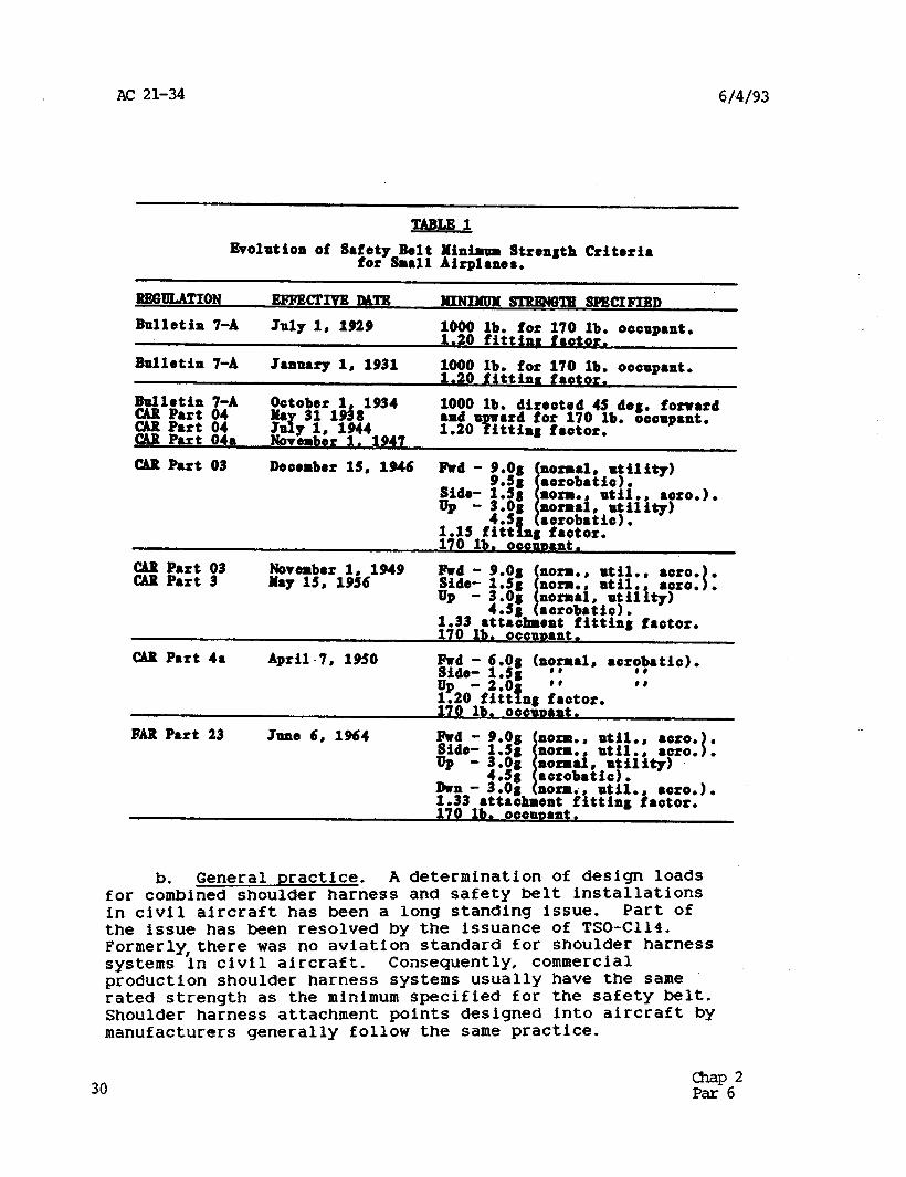
a. Strenqth criteria. Minimum strength criteria for safety belt installations have changed through the years. The form of the specifications have also changed. Table 1 highlights the evolution of minimum strength specifications for small airplanes, beginning with the first Department of Commerce "Aeronautics Bulletin" (Bulletin 7-A) to specify minimum safety belt strength, to the Civil Aeronautics Board "Civil Air Regulations" (CAR), through the Federal Aviation Administration "Federal Aviation Regulations" (FAR). The minimum strength criteria for any particular airplane in service depends on the certification basis of the airplane.
ci=P2 Par5 29
AC 21-34 6/4/93
TABLE1 Evolution of S8fetp Belt Minimum Strength Criteri8
for Sm811 Airplmes.
REGULATION BFFBcrI9B lmB HININUMSTRENGlBSPWIPIBD Bulletin 7-A July 1, 1929 1000 lb. for 170 lb. oocup8nt.
1.20 fittinr frotor.
Bulletin 7-A January 1, 1931 $0;; 'bi.fr lzOtlE. oaaup8nt. . tfa
B~lfi~~ via Ootobor Ma 311948 1 1934 1000 lb. direotod 45 forward % Rft’ ::a J&l, 1944
deg. 1.20 %Itting frotor. 8nd u l rd for 170 lb. oooup8nt.
Novombor 1, 1947 CAR P8rt 03 Deaombor 13, 1
UP - 3.on
.946 Rd-
z EE: i3 Nowmber 1, 1949 May 13, 1936
CAR P8rt 48 April-7, 1950 hd- 6.Og +m81, 8arT?8tia). #D
FAR P8rt 23 June 6, 1964
b. General practice. A determination of design loads for combined shoulder harness and safety belt installations in civil aircraft has been a long standing issue. Part of the issue has been resolved by the issuance of TSO-C114. Formerly,there was no aviation standard for shoulder harness systems in civil aircraft. Consequently, commercial production shoulder harness systems usually have the same rated strength as the minimum specified for the safety belt. Shoulder harness attachment points designed into aircraft by manufacturers generally follow the same practice.
30 k%p62
6(4/93 AC 21-34
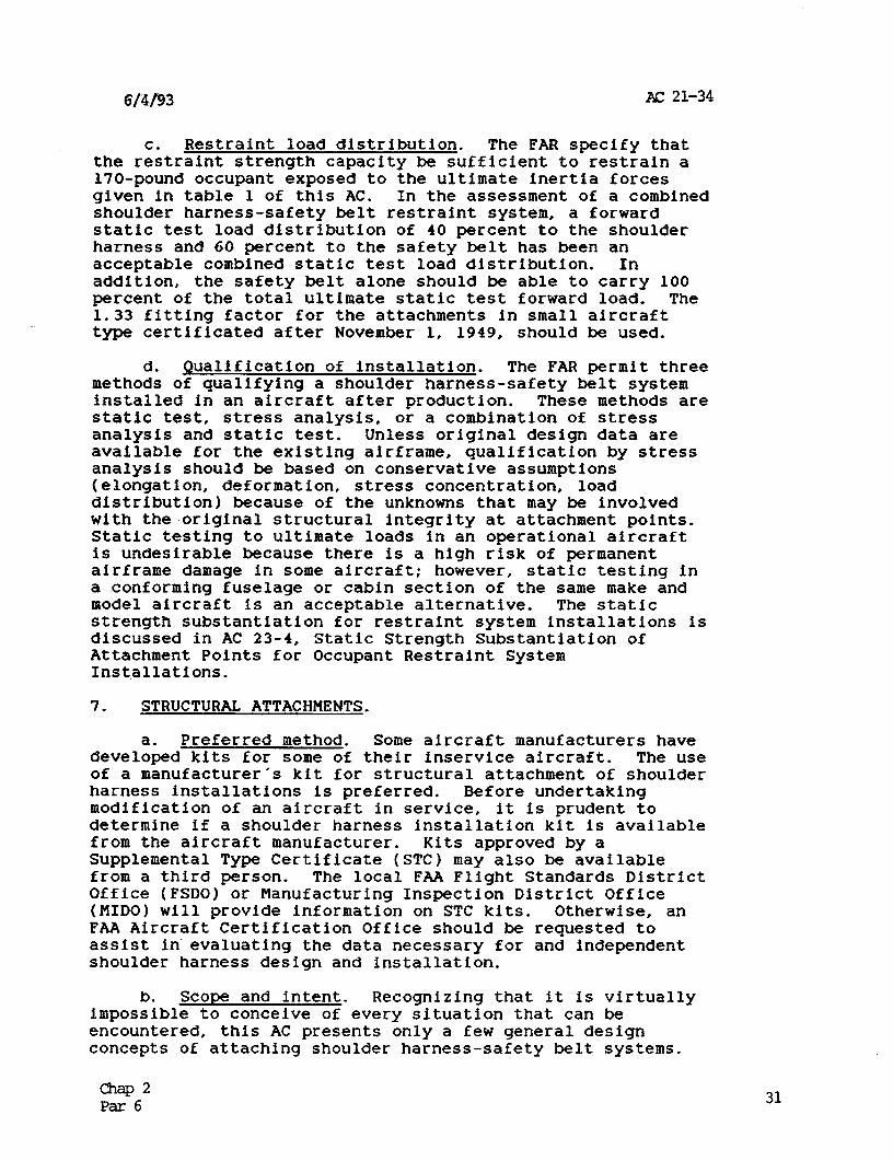
C. Restraint load distribution. The FAR specify that the restraint strength capacity be sufficient to restrain a 170-pound occupant exposed to the ultimate inertia forces given in table 1 of this AC. In the assessment of a combined shoulder harness-safety belt restraint system, a forward static test load distribution of 40 percent to the shoulder harness and GO percent to the safety belt has been an acceptable combined static test load distribution. In addition, the safety belt alone should be able to carry 100 percent of the total ultimate static test forward load. The 1.33 fitting factor for the attachments in small aircraft type certificated after November 1, 1949, should be used.
d. Qualification of installation. The FAR permit three methods of qualifying a shoulder harness-safety belt system installed in an aircraft after production. These methods are static test, stress analysis, or a combination of stress analysis and static test. Unless original design data are available for the existing airframe, qualification by stress analysis should be based on conservative assumptions (elongation, deformation, stress concentration, load distribution) because of the unknowns that may be involved with the ,original structural integrity at attachment points. Static testing to ultimate loads in an operational aircraft is undesirable because there is a high risk of permanent airframe damage in some aircraft; however, static testing in a conforming fuselage or cabin section of the same make and model aircraft is an acceptable alternative. The static strength substantiation for restraint system installations is discussed in AC 23-4, Static Strength Substantiation of Attachment Points for Occupant Restraint System Installations.
7. STRUCTURAL ATTACHMENTS.
a. Preferred method. Some aircraft manufacturers have developed kits for some of their inservice aircraft. The use of a manufacturer's kit for structural attachment of shoulder harness installations is preferred. Before undertaking modification of an aircraft in service, it is prudent to determine if a shoulder harness installation kit is available from the aircraft manufacturer. Kits approved by a Supplemental Type Certificate (STC) may also be available from a third person. The local FAA Flight Standards District Office (FSDO) or Manufacturing Inspection District Office (MID01 will provide information on STC kits. Otherwise, an FAA Aircraft Certification Office should be requested to assist in evaluating the data necessary for and independent shoulder harness design and installation.
b. Scope and intent. Recognizing that it is virtually impossible to conceive of every situation that can be encountered, this AC presents only a few general design concepts of attaching shoulder harness-safety belt systems.
cAap2 Par6 31
AL: 21-34 6/4/93
These few design concepts are intended to create an understanding of the features needed in the attachments.
(1) Concept 1. The first concept is to spread attachment loads into as much surrounding structure as possible and as gradually as possible. Gradual dissipation of loads minimizes stress concentrations at abrupt changes in material cross section which promote local failures, either immediately or upon a subsequent accident load cycle.
(2) Concept 2. The second concept is to minimize local structural bending by attachment loads. Semimonocoque structure generally offers poor resistance to bending, but is good in tension and shear applications. Airframe bending, buckling, or collapse adds to forward movement of the occupant.
(3) Concept 3. The third concept is to ensure that fastener type, strength, and number are adequate in tension, shear, and bending, depending on the application. Airframe buckling under restraint loads will result in compound loading of connector plates as well as fasteners. Concurrently, material thickness is important in preventing fastener pull-out, and continued security (safety wire or equivalent) of threaded fasteners should be considered.
C. Details of attachment. Some existing aircraft will already have shoulder harness attachment points, often called "hard points", which were installed during production. As an alternative, it is fortunate to be able to attach shoulder belts to reasonably rigid structure where only a doubler may be needed to replace the material removed for fastener holes. Most often, it is necessary to attach shoulder belts to relatively thin formed sections, or even skin panels, of semimonocoque construction to achieve a satisfactory geometric configuration of the belts when in use. In most cases, attachment points need reinforcement. Attachments to welded tube and wood frame construction present a special problem in selecting the attachment point and the hardware for attachment of shoulder belts.
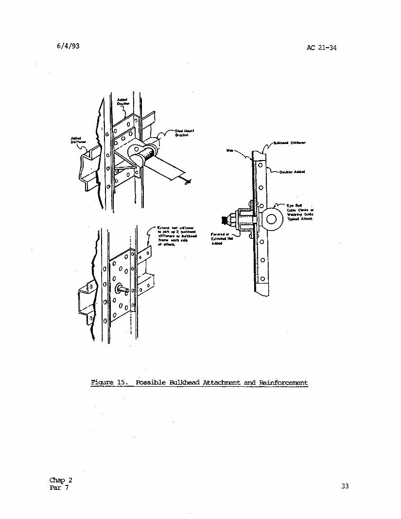
d. Bulkhead attachments. It is necessary that a bulkhead be a structural bulkhead rather than a cabin partition to offer a suitable structural attachment for a shoulder harness. Figure 15 offers generic examples of how a shoulder harness might be attached to a bulkhead. The reinforcement hat stiffener on the aft side of the bulkhead, and the intercostal doubler on the forward side, illustrate one means of distributing restraint load to the bulkhead in two directions with a minimum of added weight. Although not as effective, the added hat stiffener and intercostal doubler can be installed on reverse sides of the bulkhead when the bulkhead stiffeners are on the aft side of the bulkhead.
32 E-5”
6/4/93 AC 21-34
i
Figure 15. Possible Fib&head At WchmmtandReinforcement
33
AC 21-34 6/4/93
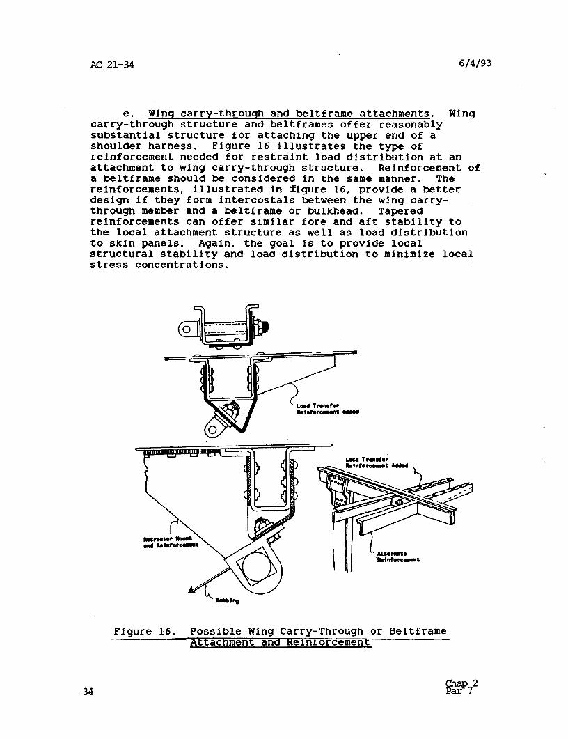
e. Winq carry-through and beltframe attachments. Wing carry-through structure and beltframes offer reasonably substantial structure for attaching the upper end of a shoulder harness. Figure 16 illustrates the type of reinforcement needed for restraint load distribution at an attachment to wing carry-through structure. Reinforcement of a beltframe should be considered in the same manner. The reinforcements, illustrated in figure 16, provide a better design if they form intercostals between the wing carry- through member and a beltframe or bulkhead. Tapered reinforcements can offer similar fore and aft stability to the local attachment structure as well as load distribution to skin panels. Again, the goal is to provide local structural stability and load distribution to minimize local stress concentrations.
Figure 16. Possible Wing Carry-Through or Beltframe Attachment and Reinforcement
6/4/93 AC 21-34
f. Stringer attachments. Direct attachment of a shoulder harness to body stringers is discouraged, because stringers are intended to carry tension loads only, and it is difficult to reinforce the stringer to support bending stresses likely to be introduced by restraint loads. Intercostals between beltframes offer the best approach to attaching a shoulder harness between beltfrazes;
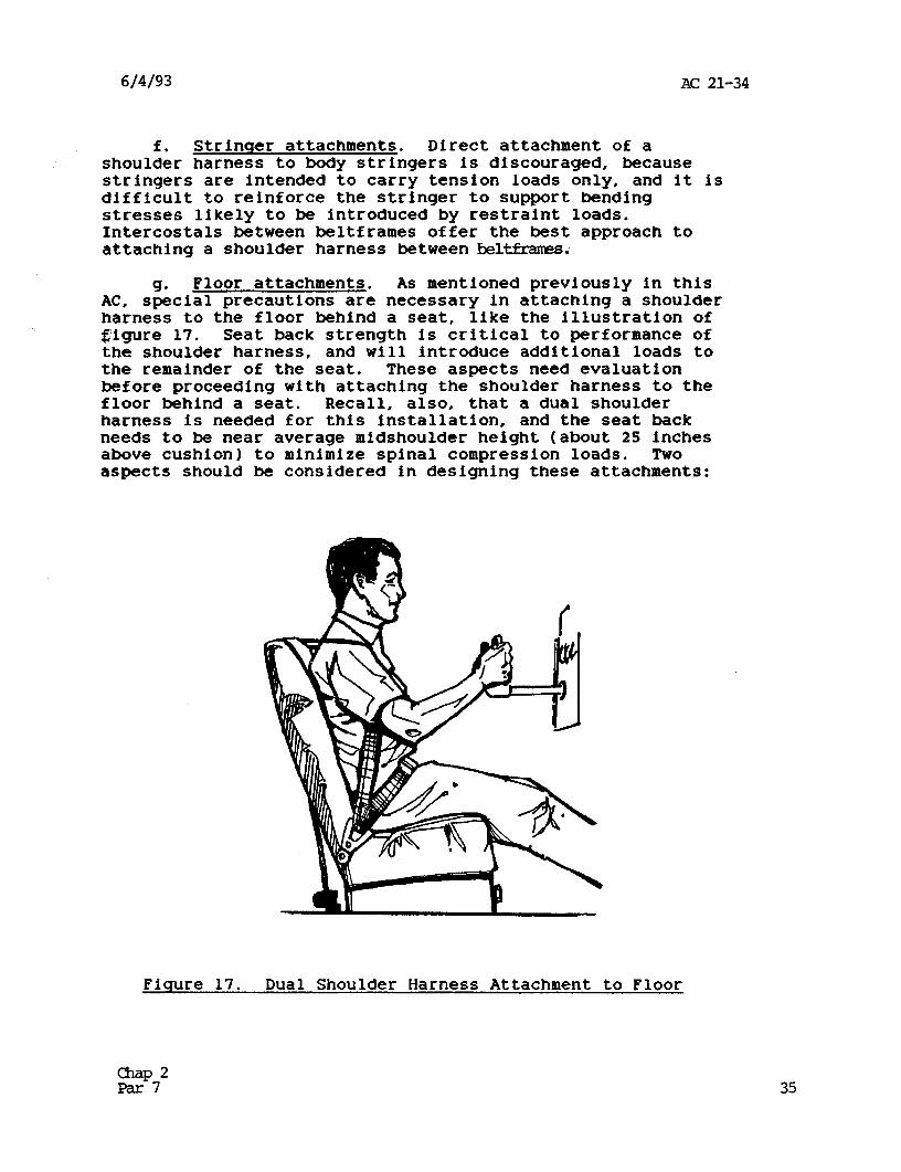
9* Floor attachments. As mentioned previously in this AC, special precautions are necessary in attaching a shoulder harness to the floor behind a seat, like the illustration of gigure 17. Seat back strength is critical to performance of the shoulder harness, and will introduce additional loads to the remainder of the seat. These aspects need evaluation before proceeding with attaching the shoulder harness to the floor behind a seat. Recall, also, that a dual shoulder harness is needed for this installation, and the seat back needs to be near average midshoulder height (about 25 inches above cushion) to minimize spinal compression loads. Two aspects should be considered in designing these attachments:
Fiqure 17. Dual Shoulder Harness Attachment to Floor
35
AC 21-34 6/4/93
(1) Reinforcement. The shoulder harness attachments at the floor may consist of an eye bolt or a connector plate; however, simple attachment to the floor panel is usually insufficient to support restraint loads. If a floor beam or other primary floor support structure is not available at the point necessary for attaching the shoulder harness, the addition of an intercostal between floor beams is warranted for connection of the eye bolt or connector plate. The intercostal will provide a beam to carry the local vertical restraint loads at the shoulder harness attaChMent.
( 2) Retractor mountinq. Recalling that most retractor frames are designed to transfer restraint loads through shear of the attachment fasteners, it may be necessary to install a vertically oriented connector plate which is anchored to a floor beam or an intercostal. The vertical plate may also be needed if the bolt-on end fitting of figure 9 is used on the shoulder harness assembly.
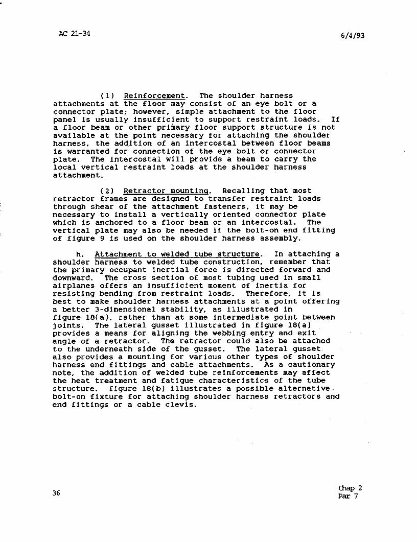
h. Attachment to welded tube structure. In attaching a shoulder harness to welded tube construction, remember that the primary occupant inertial force is directed forward and downward. The cross section of most tubing used in small airplanes offers an insufficient moment of inertia for resisting bending from restraint loads. Therefore, it is best to make shoulder harness attachments at a point offering a better 3-dimensional stability, as illustrated in figure 18( a 1, rather than at some intermediate point between joints. The lateral gusset illustrated in figure 18(a) provides a means for aligning the webbing entry and exit angle of a retractor. The retractor could also be attached to the underneath side of the gusset. The lateral gusset also provides a mounting for various other types of shoulder harness end fittings and cable attachments. As a cautionary note, the addition of welded tube reinforcements may affect the heat treatment and fatigue characteristic,s of the tube structure. figure 18(b) illustrates a possible alternative bolt-on fixture for attaching shoulder harness retractors and end fittings or a cable clevis.
36 anap 2 Par 7
6/14/93 AC 21-34
Fisure 18. Attachment and Reinforcement of Welded Tube Structure
i. Attachment to wooden structure. Experience with shoulder harness attachments to wooden structures is scarce. The goal, however, is the same as for metal structures. Distribute the restraint load from the attachment to other structure to avoid local stress concentration failure. Gussets, cross braces, and intercostakare the techniques. While it is difficult to predict the structural configuration that might be available for attaching a shoulder harness.in a wooden structure airplane, some techniques peculiar to wooden structure are worthy of mention:
(1) Nuts and bolts. The use of lag bolts or wood screws to resist restraint loads in tension is poor practice. Baits through the structural member is the preferred method.
(2) Bolt head backup. Use metal backup plates for all attachment bolts to avoid compression of the wood.
&P2 Par7 37
AC 21-34 6/4/93
(3) Wood snlfttinq. A wooden beam tends to split in the grain when loads are applied perpendicular to the grain by a shear bolt through the beam. Bolts loaded in single shear are the worst offenders. This effect can be minimized by locating the bolt hole to permit as much wood depth as possible in the direction of the applied load.
(4) Avoid qlued joint. It is good practice to avoid attaching shoulder harness mounts where restraint loads produce bending in a glued splice. If this practice is unavoidable, metal reinforcement of the splice is a suitable alternative for preventing splice separation, or bending fractures at the edge of the splice, under restraint loading.
38 Chap 2 Par7
6/4/93 AC 21-34
CHARTER 3. CONCLUSIONS
8. SUMMARY.
Intent of AC. The intent of this AC is to provide guidaice for achieving an effective shoulder harness-safety belt installation in the dynamic loading environment of an accident. It is recognized, however, that compromises are necessary in some aircraft due to the absence of sufficient structure at the ideal attachment points. Factors of hardware, geometric ramifications, strength and attachment techniques are presented to assist in making intelligent decisions in selecting and installing a shoulder harness- safety belt system. A checklist of factors to consider follows:
b. Shoulder Harness-Safety Belt Checklist.
(1) Width of webbing in contact with occupant, nominally 2.0 inches or more;
(2) Minimize webbing length for less webbing stretch;
(3) Flexible cable in lieu of guy wire cable;
(4) Buckle release force should be 12 pounds or less in the unloaded condition;
(5) Single buckle for release and escape;
(6) Webbing properly looped on length adjusters;
(7) Tilt lock adjusters lock at 30 degrees or more;
(8) Emergency locking retractors (inertia reels) engage at 0.75 to 1.5 G's;
(9) Automatic locking and emergency locking retractors mounted to provide straight line entry and exit angle of webbing (very 'important if webbing guide not present);
(10) Retractor mounts designed to resist restraint loads by shear of the retractor mounting bolts;
z?*3 39
AC 21-34 6/4/93
(11) Webbing wrapped on retractor spool does not interfere with retractor locking;
(12) Retractor spring tension sufficient to overcome webbing drag over seats and webbing guides for webbing retraction and stowage;
(13) Quick disconnect end fittings safety pinned and protected from keeper damage;
(14) Attachment position of safety belt permits a belt angle of 45 to 55 degrees for all seat positions;
(15) Webbing guides position dual shoulder belts at middle of occupant’s shoulder;
(16) Lower attachment of single diagonal shoulder belt positioned to the side of occupant’s hip;
(17) Upper attachment of single diagonal shoulder belt provides belt angle across the torso and over the approximate middle of the shoulder for various sizes of occupant and various seat positions; and
(18) Elevation angle of the shoulder belt(s) extending behind the occupant is between -5 and +30 degrees from the longitudinal to avoid spinal compression loads and/or amplified forces in shoulder belts.
C. Snecial consideration for ensineerinq. A strength evaluation should be accomplished for the following:
(1) Review for false security or possible occupant injury due to shoulder harness geometry;
(2) Integrity of existing safety belt attachments verified for change in restraint force magnitude and direction resulting from addition of shoulder harness;
(3) Integrity of rear seat leg attachments to floor, including seat tracks, relative to loads introduced by the shoulder harness;
40 i2p*3
6/4/93 AC 21-34
(4) Special evaluation of entire seat strength when upper end of shoulder harness is attached in a manner which applies restraint loads to the seat back;
(5) Structural attachment of shoulder harness to the airframe reinforced to add stability at the attachment point and distribute restraint loads to other structure;
(6) Attachment plates and fasteners adequate for initial direction of restraint loads and 210 degrees to either side;
(7) Connector plates and fasteners adequate for compound stresses from fuselage buckling when attaching a shoulder harness to overhead structure (assume a change in the direction of restraint loads of at least 2 30-degree change in the vertical plane and =lO-degree change in the horizontal plane); and
(8) Qualification by static test in a aircraft in service is undesirable, but static test in a conforming fuselage or cabin section is desirable. Conservative stress analysis is an acceptable alternative.
2*3 *U.S. G.P.O.:1993-343-273:80048 41