Embed Size (px)
Citation preview
UNIVERSITI PUTRA MALAYSIA
DESIGN AND DEVELOPMENT OF REMOTELY PUMPED ERBIUM DOPED FIBER AMPLIFIER TRANSMISSION SYSTEM
MOHD SHAHNAN BIN ZAINAL ABIDIN
FK 2004 94
DESIGN AND DEVELOPMENT OF REMOTELY PUMPED ERBIUM DOPED FIBER AMPLIFIER TRANSMISSION SYSTEM
By
MOHD SHAHNAN BIN ZAINAL ABIDIN
Thesis Submitted to the School of Graduate Studies, Universiti Putra Malaysia, in Fulfilment of the Requirements for the Degree of Master of Science
December 2004
DEDICATION
To
My Mother; SitiKhadijah Bt. Kila
My Father;
Zainal Abidin Bin Yahaya
Brothers and Sister; Mohd Faizal, Mohd Haris, Mohd Rafie, Siti Nurathirah
Relatives, Friends, Teachers and Neighbours
Abstract of thesis presented to the Senate of Universiti Putra Malaysia in fulfilment of the requirement for the degree of Master of Science
DESIGN AND DEVELOPMENT OF REMOTELY PUMPED ERBIUM DOPED FIBER AMPLIFIER TRANSMISSION SYSTEM
By
MOHD SHAHNAN BIN ZAINAL ABIDIN
December 2004
Chairman: Associate Professor Mohd Adzir Mahdi, Ph.D. Faculty: Engineering
Erbium Doped Fiber Amplifier (EDFA) has been deployed extensively in optical
communication systems especially for a long haul transmission link. Basically,
EDFA requires a local pump laser for its optical amplification. This design will
encounter problem if the amplifier is located at the middle of transmission line where
power supply for the pump laser is unavailable. Therefore, remotely pumped
amplifier can overcome the problem by injecting the pump light from either side of
the transmission ends; transmitter or receiver.
This dissertation reveals a new technique of designing a repeaterless transmission
system using a remotely pumped EDFA. By varying the length of transmission fiber
before and after EDFA, its location can be optimized for a specific pump power. A
bit error rate is used as the main performance parameter and its threshold value is set
at better than 10-10. The optimized location of EDFA will lead to the maximum
transmission distance where it is found that the location of EDFA is closer to the
receiver side.
ii

In conclusion, the EDFA location on transmission line using remotely pumped
technique gives major impact to the system’s performance.
iii
Abstrak tesis yang dikemukakan kepada Senat Universiti Putra Malaysia sebagai memenuhi keperluan untuk ijazah Master Sains
REKABENTUK DAN PEMBANGUNAN SISTEM TRANSMISI PENGUAT
GENTIAN TERDOP ERBIUM DIPAM SECARA JAUH
Oleh
MOHD SHAHNAN BIN ZAINAL ABIDIN
Disember 2004
Pengerusi: Profesor Madya Mohd Adzir Mahdi, Ph.D. Fakulti: Kejuruteraan Penguat Gentian Terdop Erbium (EDFA) telah digunakan secara meluas di dalam
sistem komunikasi optikal terutamanya untuk sistem talian transmisi panjang. Secara
dasarnya, EDFA memerlukan laser pam setempat untuk penguatan optiknya.
Rekabentuk ini akan menghadapi masalah jika penguat itu diletakkan di tengah talian
transmisi di mana bekalan kuasa untuk laser pam tidak dapat diperolehi. Oleh itu,
penguat dipam secara jauh mampu mengatasi masalah ini dengan menyuntik cahaya
pam daripada mana-mana belah hujung transmisi; penghantar atau penerima.
Tesis ini mendedahkan suatu teknik baru dalam merekabentuk sistem transmisi tanpa
ulangan menggunakan EDFA yang dipam secara jauh. Dengan mengubah panjang
gentian transmisi sebelum dan selepas EDFA, lokasinya boleh dioptimumkan bagi
kuasa pam yang spesifik. Kadar kesilapan bit diguna sebagai parameter prestasi dan
nilai ambang ditetapkan kepada lebih baik daripada 10-10. Lokasi EDFA yang
optimum akan membawa kepada jarak transmisi maksimum yang mana didapati
bahawa lokasi EDFA tersebut adalah lebih dekat kepada sebelah penerima.
iv

Kesimpulannya, lokasi EDFA pada talian transmisi menggunakan teknik pam secara
jauh memberi kesan yang besar kepada prestasi sistem.
v

ACKNOWLEDGEMENTS
Alhamdulillah, thanks to ALLAH the almighty. All blessing to Prophet Muhammad,
may Allah bless upon him.
My acknowledgement firstly goes to supervisor Associate Professor Dr. Mohd Adzir
Mahdi, for his continuous and valuable advices since the early stages of the research.
His professional thoughts, comments and opinions in have guided me on a right
track. I thank also to both members of the supervisory committee, Mr. Mohd Hanif
Yaacob and Mrs. Siti Barirah Ahmad Anas.
A special gratitude to all my friends in Photonic and Fiber Optics System
Laboratory, Engineering Faculty, University Putra Malaysia. Your constant support
gives additional strength to complete the thesis. Not to forget as well staffs of
Kulliyyah Engineering, International Islamic University Malaysia.
Millions of appreciations are bound for Wan Farha Bt. Wan Abdul Fatah for the
inspiration from the beginning of the research. Finally to my parent, Siti Khadijah Bt.
Kila and Zainal Abidin Bin Yahaya, for the understanding until the end of my study.
vi
I certify that an Examination Committee met on 30th December 2004 to conduct the final examination of Mohd Shahnan bin Zainal Abidin on his Master of Science thesis entitled “Design and Development of Remotely Pumped Erbium Doped Fiber Amplifier Transmission System” in accordance with Universiti Pertanian Malaysia (Higher Degree) Act 1980 and Universiti Pertanian Malaysia (Higher Degree) Regulations 1981. The Committee recommends that the candidate be awarded the relevant degree. Members of the Examination Committee are as follows: Khairi Yusof, Ph.D. Lecturer Faculty of Engineering Universiti Putra Malaysia (Chairman) Mohamad Khazani Abdullah, Ph.D. Associate Professor Faculty of Engineering Universiti Putra Malaysia (Member) Syed Javaid Iqbal, Ph.D. Lecturer Faculty of Engineering Universiti Putra Malaysia (Member) Harith Ahmad, Ph.D. Professor Faculty of Science Universiti Malaya (Independent Examiner) __________________________________ GULAM RUSUL RAHMAT ALI, Ph.D. Professor/Deputy Dean School of Graduate Studies Universiti Putra Malaysia Date:
vii
This thesis submitted to the Senate of Universiti Putra Malaysia and has been accepted as fulfilment of the requirement for the degree of Master of Science. The members of Supervisory Committee are as follows: MOHD ADZIR MAHDI, Ph.D. Associates Professor Faculty of Engineering Universiti Putra Malaysia (Chairman) MOHD HANIF BIN YAACOB Lecturer Faculty of Engineering Universiti Putra Malaysia (Member) SITI BARIRAH BT AHMAD ANAS Lecturer Faculty of Engineering Universiti Putra Malaysia (Member)
_______________________ AINI IDERIS, PhD Professor/Dean School of Graduate Studies Universiti Putra Malaysia Date:
viii
DECLARATION
I hereby declare that the thesis is based on my original work except for the quotation and citations which have been duly acknowledged. I also declare that it is not been previously or concurrently submitted for any other degree at UPM or other institutions.
_____________________________________ MOHD SHAHNAN BIN ZAINAL ABIDIN Date:
ix
TABLE OF CONTENTS Page ABSTRACT ii ABSTRAK iv ACKNOWLEDGEMENTS vi APPROVAL vii DECLARATION ix LIST OF TABLES xii LIST OF FIGURES xiii LIST OF ABBREVIATIONS xvi CHAPTERS 1 INTRODUCTION 1 1.1 Background 1 1.2 Optical Communication System 2 1.3 Optical Amplifiers 3 1.3.1 Earth Rare Doped Fiber Amplifier 5 1.3.2 Optical Amplifier Classification 5 1.4 Problem Statement and Critical Review 8 1.5 Research Objectives 9 1.6 Scope of the Work 10 1.7 Organization of the Thesis 11 2 THEORY 12 2.1 Introduction 12 2.2 Optical Amplification Fundamental 12 2.3 Energy level of Erbium Ions 16 2.4 Three Level Laser System 18 2.4.1 Three Level Atomic Rate Equations System 18 2.4.2 Signal with Amplified Spontaneous Emission Power Rate
Equations 22
2.4.3 Pump Power Rate Equations 26 2.5 Reduction to Two Level System from Three Level System 28 2.6 Repeaterless Transmission System 30 2.6.1 System Development 30 2.6.2 Applications 31 2.6.3 System Technologies 32 2.6.4 System Configuration 38 2.7 Summary 40 3 RESEARCH METHODOLOGY 41 3.1 Introduction 41 3.2 Experimental Setup 41 3.3 Components in Remotely Pumped EDFA 43 3.3.1 Isolator 44 3.3.2 Wavelength Selective Coupler 44 3.3.3 1480 nm Pump Laser 45
x
3.3.4 Erbium Doped Fiber 46 3.3.5 Variable Optical Attenuator 47 3.3.6 Test Equipment and Measurement Devices 48 3.3.7 Optical Spectrum Analyzer 49 3.3.8 Tunable Laser Source 49 3.4 Characterization of Erbium Doped Fiber Amplifier 50 3.5 Repeaterless Transmission System Using Remotely Pumped EDFA 52 3.5.1 Fiber Background Loss 52 3.5.2 Bit Error Rate Test 54 3.5.3 Maximum Transmission Distance 55 3.5.4 EDFA Location 56 3.5.5 Pump Power Requirement 56 3.6 Parameter Under Study 57 3.6.1 Design Parameter 57 3.6.2 Performance Parameter 59 3.7 Summary 60 4 RESULTS AND DISCUSSION 61 4.1 Introduction 61 4.2 Erbium Doped Fiber Amplifier Characterization 61 4.2.1 Pump Power Effect on Gain and Noise Figure 61 4.2.2 Pump Power Effect on Output Power 64 4.2.3 Operating Range of Pump Power 65 4.2.4 Input Power Effect on Gain and Noise Figure 67 4.2.5 Input Power Effect on Output Power and OSNR 70 4.2.6 Wavelength Effect on System Gain and Noise Figure 71 4.3 EDFA Transmission Performance 73 4.3.1 EDFA Position on Transmission Line 74 4.3.2 Optimum Parameter for Specific Transmission Total
Distance 82
4.3.3 Effect of System Upgrade to OSNR Performance 89 4.3.4 Gain Improvement over Different Wavelength 91 4.4 Summary 92 5 CONCLUSION AND FUTURE WORKS 94 5.1 Conclusion 94 5.2 Future Work 95 REFERENCES 97 BIODATA OF THE AUTHOR 103 PUBLICATIONS 104
xi
LIST OF TABLES
Table Page
3.1 Specifications of erbium doped fiber used for the experiments 47
3.2 Required test time for BER measurement at different transmission speed
55
4.1 Fiber length before and after EDFA associated with maximum
total transmission distance and percentage of amplifier location from transmitter side
77
4.2 Performance parameter summary of remotely pumped EDFA
transmission system 82
xii
LIST OF FIGURES
Figure Page
1.1 Optical fiber amplifier classification; (a) Post amplifier (b) Inline amplifier (c) Preamplifier
7
1.2 Scope of research work 10
2.1 Energy level diagram 13
2.2 Atom with respective energy level (a) with external energy
and (b) releases photon 15
2.3 Energy levels of erbium ions with possible pump bands. 16
2.4 Energy level system corresponding to three-level system. 19
2.5 Cylindrical fiber cross section 22
2.6 Energy level of two-level system 29
2.7 Signal evolution of distributed amplifier for different pumping
schemes 33
2.8 Signal power evolution experienced by remotely pumped
EDFA systems 35
2.9 Remotely pumped EDFA incorporating circulators to achieve
double pass amplification 36
2.10 Additional pumping line utilized providing more pump power
to remotely pumped EDFA 36
2.11 Deployment of filter within pumping line 37
2.12 Various configuration of repeaterless transmission systems 38
2.13 Signal power evolution over transmission distance for
different repeaterless systems 39
3.1 Experimental setup of EDFA 42
3.2 Setup of EDFA experiment for repeaterless transmission
system using remotely pumped EDFA 43
3.3 Basic operation of isolator 44 3.4 Inputs and output associates with wavelength selective
coupler 45
xiii
3.5 Structure of pump laser module 46
3.6 Experimental setup associating transmitter, receiver and BERT
48
3.7 Output power response for a current applied to 1480 nm pump
laser 50
3.8 Screenshot from OSA for measurement technique for gain,
ASE level, noise figure and output power. 51
3.9 Fiber loss associates with respective wavelength of signal 54
4.1 Gain and noise figure characteristics using single-pass EDFA
at different signal powers 62
4.2 Output power against pump power for various input power 65
4.3 Gain Conversion Efficiency over consumed pump power for a
range of input signal power from - 40 to - 4 dBm 66
4.4(a) Gain and noise figure against various pump power for -40
dBm to 0 dBm input power 68
4.4(b) ASE level over signal wavelengths at input power of -30 dBm
at 40 mW pump power 69
4.5(a) Output power and OSNR against input power for 30, 40 and
50 mW pump power 70
4.5(b) ASE level over signal wavelengths at input power of 0 dBm at
40 mW pump power 71
4.6 Gain and noise figure variation over wavelength. Input power
is set to -20 dBm for 30, 40 and 50 mW 73
4.7 EDFA position configuration on remotely-pumped
transmission experiment 74
4.8 Maximum transmission length at BER better than 10-10 with
respect of EDFA location on transmission line for pump powers of 30, 40 and 50 mW. Launch power from transmitter side is set to be 0 dBm
76
4.9 Eye diagram of the transmission for pump powers of (a) 30
mW, (b) 40 mW and (c) 50 mW 76
4.10 Gain and noise figure performance over EDFA location 78
xiv
4.11 OSNR and received power performance over EDFA location on transmission line
79
4.12 Consumed pump power associated with EDFA location, the
local pump power of 40 mW is used 81
4.13 Bit Error Rate for total transmission distance of 180 km. 83
4.14 BER for 196 km of total transmission distance for 40 mW
pump power injected at input EDFA 84
4.15 BER for 208 km transmission distance for 40 mW pump
power at EDFA input 86
4.16 BER for 215.18 km transmission distance for 40 mW pump
power at EDFA input 86
4.17 OSNR and received power over EDFA location at 208 km
total transmission system for 40 mW pump power at EDFA input
89
4.18 OSNR requirement for system upgrade from 2.5 to 10 Gbps 91
4.19 Gain and noise figure difference in respect to reference point
at 1550.3 nm 92
xv
LIST OF ABBREVIATIONS
ASE - Amplified Spontaneous Emission
BER - Bit Error Rate
BERT - Bit Error Rate Tester
DCF - Dispersion Compensating Fiber
DUT - Device Under Test
EDF - Erbium Doped Fiber
EDFA - Erbium Doped Fiber Amplifier
FEC - Forward Error Correction
G - Gain
GCE - Gain Conversion Efficiency
LD - Laser Diode
NA - Numerical Aperture
OSA - Optical Spectrum Analyzer
OSNR - Optical Signal to Noise Ratio
PRBS - Pseudo-Random Bit Sequence
PCE - Power Conversion Efficiency
PPM - Part Per Million
SOA - Semiconductor Optical Amplifier
TLS - Tunable Laser Source
VOA - Variable Optical Attenuator
WDM - Wavelength Division Multiplexing
WSC - Wavelength Selective Coupler
xvi
CHAPTER 1
INTRODUCTION
Telecommunication industries evolve rapidly since past years influenced by hungry
demanding competition among manufacturers. Various telecommunication
technologies have been created and innovated in order to achieve manufactures need
for a reliable telecommunication quality more than just voice services. Higher
bandwidths are required to satisfy a real time video on demand, live telecast and
interactive applications. An optical communication is seen as one of the enabling
technologies and being one of the key factors for the present and future applications.
This chapter will explain briefly about optical communication systems and its
development up to date. Later, optical amplifiers will be highlighted by focusing to
rare-earth doped fiber amplifier. Statement of related problem and scope of the
research to be conducted are discussed in details as well as its objectives to achieve.
1.1 Background
Optical fiber communication systems can fulfill the bandwidth need for a practical
long haul transmission distance. It is reliable in handling and transmitting data over
hundreds of kilometers with an acceptable bit error rate. Worldwide researchers
continuously update the technology to improve the system’s performance.
Typically, a link of optical fiber communication can be hundreds of kilometers and
some could be extended up to several thousands of kilometers with an additional
1
amplifiers and repeaters [1]. Data speed of each optical fiber transmission channel
could reach up to 40 Gb/s [2] and it is limited by polarization-mode and chromatic
dispersions, attenuation, and nonlinearity of the fiber [3]. Some schemes included
into the system to improve the transmission distance and bit rate further such as
Forward Error Correction (FEC), new remote pumping schemes and utilization of
dispersion compensating fibers [4]. Optical fiber communication growths
impressively with over 600 millions kilometers of fiber optics have been installed
worldwide [5] with USD 1.2 billion amounted only for equipment of optical
transport for the year of 2000 only [6].
1.2 Optical Communication System
Basically an optical communication system consists of a link of fiber optic as a
transmission medium between a transmitter and a receiver. Information is converted
from electrical to optical domain, modulated and multiplexed before injecting into
the fiber optic. Optical fiber carries the information by guiding the laser beam in its
core utilizing a total internal reflection requirement. At the receiver end, the signal is
converted back into an electrical domain by a photodetector, amplified and
demodulated to produce the original signal.
Between two transmission ends, an amplifier could be added to extend the link.
Previously, electrical amplifiers were utilized by converting optical signal into
electrical domain before it was amplified. Electrical amplifiers require external
power supply to operate and this would become a big problem if a submarine
transmission link is going to be deployed. The optical amplifier overcomes this
2
barrier since the system uses light to amplify the information signals all optically and
light can be send from a distance.
1.3 Optical Amplifiers
Traditionally, an electrical amplifier converts optical signal into electrical domain
first before converts back again into optical signal after amplifying it. The state of
signal changes several times as there are several stages of electrical amplifiers. This
would add more delay in transmission and would affect the overall system bit error
rates.
Every transmission medium introduces some signal losses of its signal power. The
signal is attenuated along the medium as it travels from transmitter to receiver end. In
an optical fiber communication, the attenuation causes the launched signal power
level to decrease mainly due to signal absorption by the fiber itself.
Optical amplifiers are designed in such a way that the weakened signal is boosted to
a specific power level for the next transmission sequent. As its name implies, optical
amplifiers operate in optical domain and maintain signal’s state along fiber within
the transmission distance. They eliminate a need for signal interconversion of
photons to electrons. Moreover, they offer a simple setup of a single in line
components arrangement which is practical for any kind of modulations and
transparent to any transmission speeds [7]. Multiple optical wavelengths can be
3
easily amplified over a certain bandwidth that is limited by the operating range of
optical amplifiers.
There are two main techniques to achieve optical amplification. Semiconductor
Optical Amplifier (SOA) uses a fundamental of stimulated emission to amplify an
optical information signal. The information signal is amplified in a semiconductor’s
active region where the injection current is applied to deliver the external energy to
pump electron at the conduction band. The signal stimulates the electron transition
and emits photons with the same energy and wavelength as the input’s [8]. SOA can
be used in both nonlinear and linear modes of operation [9, 10]. But on the other
hand, the SOA is unsuitable to be utilized in a repeaterless transmission system due
to its operation requirement for an inline electrical source.
The second type of optical amplification is the use of rare-earth doping material
inside the fiber. Essentially it is a spliced active fiber connected to a pump laser
within a transmission line [11]. It works on the principle of stimulated emission; the
pump laser is used to provide energy and to excite ions in a special doped fiber to an
upper energy level. Then, the ions are stimulated by photons of the information
signal and fall down to lower level of energy; subsequently, emits photon energy
exactly at the same wavelength of the signal.
4
1.3.1 Rare-Earth Doped Fiber Amplifier
Currently research works are concentrating more on the erbium dopant, particularly
in silica based fibers. This is due to the emission of Er3+ ion lying within a set of
wavelength around 1550 nm where the silica fiber exhibits the minimum attenuation
of the information signal. Erbium doped fiber amplifiers (EDFA) could provide gains
as high as 40 dB associated with low noise, as successfully demonstrated within a
pump power range of 50 to 100 mW [12-14].
The first rare earth doped material of Neodymium (Nd ) 3+ used into a single mode
fiber was demonstrated in 1983 by Bell Telephone Laboratories [15, 16]. Since then,
rare-earth doped fibers were fabricated in a variety of methods to suit the different
designs of amplifiers. The amount of dopant inside the fiber core ranging from 100 to
2000 parts per million (ppm) up to as high as 5000 ppm [17]. Various methods used
to provide a low loss optical fiber communication with an introduction of new
composition to improve the performance of amplifier, as well as uniformity of
doping along the longitudinal and transverse fiber axes [18-22].
1.3.2 Optical Amplifier Classification
Optical fiber amplifiers generally can be classified and categorized based on its
position in transmission lines which in turn shows their respective applications.
There are three basic types of amplifier; post, inline and preamplifiers.
5
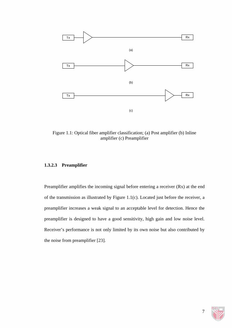
1.3.2.1 Post-amplifier
Known as a booster and power amplifier, a post amplifier is located just after a
transmitter (Tx) before the launched signal goes down to fiber as depicted by Figure
1.1(a). As its location is near to the transmitter, the post amplifier handles relatively
high power signals compared to other types of optical amplifiers. Mainly the post
amplifier’s function is to boost the signal power to the highest level hence maximizes
the transmission distance. It differs than a normal amplifier as it relieves a need for a
transmitter to produce a maximum optical power.
1.3.2.2 Inline Amplifier
An inline amplifier as shown by Figure 1.1(b) is usually located in the middle of a
transmission span. It functions to compensate the power losses along the fiber link
and could be cascaded to extend the transmission length. As it amplifies the signal
several times in the case of cascaded system, the noise level is to be kept at a
minimal level. For a WDM system, its stability to produce a uniform gain among
wavelengths becomes its main goal.
6
Tx
RxTx
Tx Rx
Rx
(a)
(b)
(c)
Figure 1.1: Optical fiber amplifier classification; (a) Post amplifier (b) Inline amplifier (c) Preamplifier
1.3.2.3 Preamplifier
Preamplifier amplifies the incoming signal before entering a receiver (Rx) at the end
of the transmission as illustrated by Figure 1.1(c). Located just before the receiver, a
preamplifier increases a weak signal to an acceptable level for detection. Hence the
preamplifier is designed to have a good sensitivity, high gain and low noise level.
Receiver’s performance is not only limited by its own noise but also contributed by
the noise from preamplifier [23].
7
![Tunable Erbium-Doped Fiber Lasers Using Various Inline Fiber … · 2016-02-18 · erbium-doped fiber lasers [4], distributed feedback fiber lasers [5], and Brillouin erbium-doped](https://img.pdfslide.us/doc/110x75/5f5d6d92d306cb22521e3c0b/tunable-erbium-doped-fiber-lasers-using-various-inline-fiber-2016-02-18-erbium-doped.jpg)