Embed Size (px)
Citation preview
Research ArticleCharacterization of Erbium Substituted Yttrium Iron GarnetFilms Prepared by Sol-Gel Method
Ramadan E. Shaiboub1 and N. B. Ibrahim2
1 Physics Department, Faculty of Education, University of Algabel Alghrbi, Nalut, Libya2 School of Applied Physics, Faculty of Science and Technology, Universiti Kebangsaan Malaysia, 43600 Bangi, Selangor, Malaysia
Correspondence should be addressed to Ramadan E. Shaiboub; [email protected]
Received 21 November 2013; Revised 4 March 2014; Accepted 13 March 2014; Published 6 April 2014
Academic Editor: Stephane Daniele
Copyright © 2014 R. E. Shaiboub and N. B. Ibrahim. This is an open access article distributed under the Creative CommonsAttribution License, which permits unrestricted use, distribution, and reproduction in any medium, provided the original work isproperly cited.
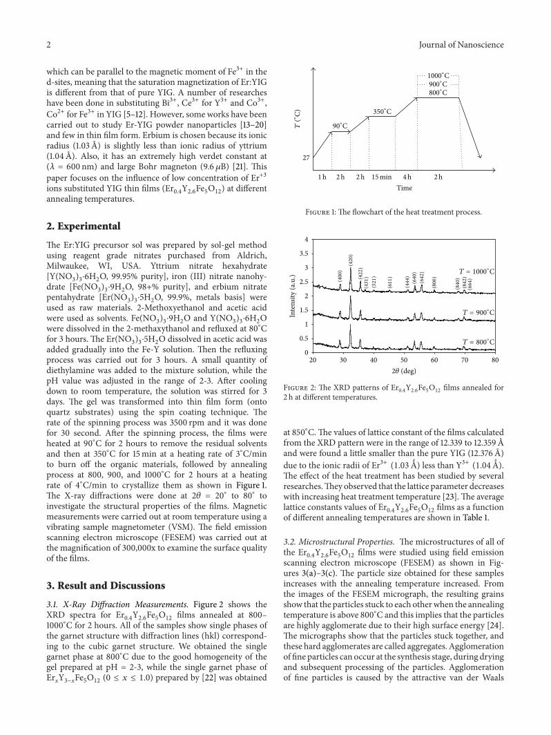
Yttrium iron garnet (YIG) thin films substituted erbium ions (Er+3) Er0.4Y2.6Fe5O12
films were prepared by a sol-gel method atdifferent temperatures which varied from 800 to 1000∘C for 2 hours in air. Magnetic and microstructural properties of the filmswere characterized with X-ray diffraction (XRD), the field emission scanning electron microscopy (FESEM), and vibrating samplemagnetometer (VSM). The XRD patterns of the sample have only peaks of the garnet structure. The lattice constants decrease,while the particle size increases from 51 to 85 nm as the annealing temperature increases with average in thickness of 300 nm. Thesaturation magnetization and the coercivity of the samples increased from 26 (emu/cc) and 28Oe for the film annealed at 800∘C to76 (emu/cc) and 45Oe for film annealed at 1000∘C, respectively.
1. Introduction
The study of yttrium iron garnet (YIG) thin films is becomingmore important because of properties that can be exten-sively used in optical communication [1], magneto-opticaldevices, and applied in microwave [2]. YIG is the mostrepresentative and well-known compound among the rare-earth garnets and various magnetizations can be achievedby substitution process. Thin and thick films have beenproduced in garnets using different methods such as liquidphase epitaxy, sputtering, chemical vapor deposition, liquidphase epitaxy, laser ablation, and sol-gel. In recent years,sol-gel methods have attracted much attention due to useof lower synthetic temperature to produce finer and morehomogeneous particles. The sol-gel synthetic method hasbeen widely used to prepare nanostructured films and canbe used to systematically vary the chemical composition oftarget compounds over pulsed laser deposition and sputter-ing techniques which are also compatible with the fabricationof nanoscaled thin films. So in this study, sol-gel method isused to achieve homogeneous systems with respect to thedesired metals. YIG is a ferromagnetic material and it has
a cubic structurewith a space group Ia3dwith the general unitformula (Y
3Fe5O12) [3]. The magnetic ions are distributed
over three crystallographic sites with sublattice magnetiza-tion Ma [octahedral site, 16 Fe3+ ions in a], Md (tetrahedralsite, 24 Fe3+ ions in d), and Mc {dodecahedral site, 24 Y3+ions in c}. Ionic distribution in garnet is represented as{Y3+3} [Fe3+2] (Fe3+3) O12
2−. The interaction between the Fe3+ions in [a] and (d) sites is strongly antiferromagnetic due tostrong superexchange interaction. The magnetic moment ofthe rare-earth ions in the {c} sublattice couples antiparallelwith the resultant moment of Fe3+ ions. In a YIG system,nonmagnetic Y3+ ions occupy dodecahedral {c} sites andmagnetic Fe3+ ions occupy octahedral [a] and tetrahedral (d)sites. The magnetic moment caused by two Fe3+ ions in [a]site is aligned antiparallel to that caused by three Fe3+ ionsin (d) site, leaving a net moment from Fe3+ in the d-site.Therefore, the saturation magnetization of YIG is given bythe magnetic Fe3+ in the d-sites. The paramagnetic trivalentEr3+ ions can be substituted for nonmagnetic Y3+ ions in{c} sites, but not for Fe3+ ions in [a] or (d) sites [4]. Themagnetic moment of Er3+ substituted for Y3+ in {c} sites,
Hindawi Publishing CorporationJournal of NanoscienceVolume 2014, Article ID 158946, 5 pageshttp://dx.doi.org/10.1155/2014/158946
2 Journal of Nanoscience
which can be parallel to the magnetic moment of Fe3+ in thed-sites, meaning that the saturation magnetization of Er:YIGis different from that of pure YIG. A number of researcheshave been done in substituting Bi3+, Ce3+ for Y3+ and Co3+,Co2+ for Fe3+ in YIG [5–12]. However, some works have beencarried out to study Er-YIG powder nanoparticles [13–20]and few in thin film form. Erbium is chosen because its ionicradius (1.03 A) is slightly less than ionic radius of yttrium(1.04 A). Also, it has an extremely high verdet constant at(𝜆 = 600 nm) and large Bohr magneton (9.6 𝜇B) [21]. Thispaper focuses on the influence of low concentration of Er+3ions substituted YIG thin films (Er
0.4Y2.6Fe5O12) at different
annealing temperatures.
2. Experimental
The Er:YIG precursor sol was prepared by sol-gel methodusing reagent grade nitrates purchased from Aldrich,Milwaukee, WI, USA. Yttrium nitrate hexahydrate[Y(NO
3)3⋅6H2O, 99.95% purity], iron (III) nitrate nanohy-
drate [Fe(NO3)3⋅9H2O, 98+% purity], and erbium nitrate
pentahydrate [Er(NO3)3⋅5H2O, 99.9%, metals basis] were
used as raw materials. 2-Methoxyethanol and acetic acidwere used as solvents. Fe(NO
3)3⋅9H2O and Y(NO
3)3⋅6H2O
were dissolved in the 2-methaxythanol and refluxed at 80∘Cfor 3 hours. The Er(NO
3)3⋅5H2O dissolved in acetic acid was
added gradually into the Fe-Y solution. Then the refluxingprocess was carried out for 3 hours. A small quantity ofdiethylamine was added to the mixture solution, while thepH value was adjusted in the range of 2-3. After coolingdown to room temperature, the solution was stirred for 3days. The gel was transformed into thin film form (ontoquartz substrates) using the spin coating technique. Therate of the spinning process was 3500 rpm and it was donefor 30 second. After the spinning process, the films wereheated at 90∘C for 2 hours to remove the residual solventsand then at 350∘C for 15min at a heating rate of 3∘C/minto burn off the organic materials, followed by annealingprocess at 800, 900, and 1000∘C for 2 hours at a heatingrate of 4∘C/min to crystallize them as shown in Figure 1.The X-ray diffractions were done at 2𝜃 = 20∘ to 80∘ toinvestigate the structural properties of the films. Magneticmeasurements were carried out at room temperature using avibrating sample magnetometer (VSM). The field emissionscanning electron microscope (FESEM) was carried out atthe magnification of 300,000x to examine the surface qualityof the films.
3. Result and Discussions
3.1. X-Ray Diffraction Measurements. Figure 2 shows theXRD spectra for Er
0.4Y2.6Fe5O12
films annealed at 800–1000∘C for 2 hours. All of the samples show single phases ofthe garnet structure with diffraction lines (hkl) correspond-ing to the cubic garnet structure. We obtained the singlegarnet phase at 800∘C due to the good homogeneity of thegel prepared at pH = 2-3, while the single garnet phase ofErxY3−xFe5O12 (0 ≤ 𝑥 ≤ 1.0) prepared by [22] was obtained
800∘C
900∘C
1000∘C
27
90∘C
350∘C
T(∘
C)
Time1h 2h 2h 15min 4h 2h
Figure 1: The flowchart of the heat treatment process.
0
0.5
1
1.5
2
2.5
3
3.5
4
20 30 40 50 60 70 80
Inte
nsity
(a.u
.)
T = 800∘C
T = 900∘C
T = 1000∘C
(400
)
(420
)
(422
)(431
)(521
)
(611
)
(444
)(640
)(642
)
(800
)
(840
)(842
)(664
)
2𝜃 (deg)
Figure 2: The XRD patterns of Er0.4Y2.6Fe5O12
films annealed for2 h at different temperatures.
at 850∘C.The values of lattice constant of the films calculatedfrom the XRD pattern were in the range of 12.339 to 12.359 Aand were found a little smaller than the pure YIG (12.376 A)due to the ionic radii of Er3+ (1.03>) less than Y3+ (1.04>).The effect of the heat treatment has been studied by severalresearches.They observed that the lattice parameter decreaseswith increasing heat treatment temperature [23].The averagelattice constants values of Er
0.4Y2.6Fe5O12films as a function
of different annealing temperatures are shown in Table 1.
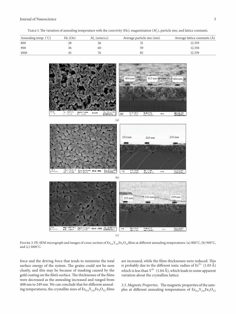
3.2. Microstructural Properties. The microstructures of all ofthe Er
0.4Y2.6Fe5O12
films were studied using field emissionscanning electron microscope (FESEM) as shown in Fig-ures 3(a)–3(c). The particle size obtained for these samplesincreases with the annealing temperature increased. Fromthe images of the FESEM micrograph, the resulting grainsshow that the particles stuck to each otherwhen the annealingtemperature is above 800∘C and this implies that the particlesare highly agglomerate due to their high surface energy [24].The micrographs show that the particles stuck together, andthese hard agglomerates are called aggregates. Agglomerationof fine particles can occur at the synthesis stage, during dryingand subsequent processing of the particles. Agglomerationof fine particles is caused by the attractive van der Waals
Journal of Nanoscience 3
Table 1: The variation of annealing temperature with the coercivity (Hc), magnetization (𝑀𝑠), particle size, and lattice constants.
Annealing temp. (∘C) Hc (Oe) 𝑀𝑠(emu/cc) Average particle size (nm) Average lattice constants (A)
800 28 26 51 12.359900 36 60 59 12.3581000 45 76 85 12.339
415nm404nm 404nm
Pa 1
Pa R1
Pa 2
Pa R2Pa R3
Pa 3
(a)
243nm252nm 235nm
Pa 1
Pa R1
Pa 2
Pa R2Pa R3
Pa 3
(b)
255nm 252nm 239nm
Pa 1
Pa R1
Pa 2
Pa R2Pa R3
Pa 3
(c)
Figure 3: FE-SEMmicrograph and images of cross-section of Er0.4Y2.6Fe5O12films at different annealing temperatures: (a) 800∘C, (b) 900∘C,
and (c) 1000∘C.
force and the driving force that tends to minimize the totalsurface energy of the system. The grains could not be seenclearly, and this may be because of masking caused by thegold coating on the film’s surface.The thicknesses of the filmswere decreased as the annealing increased and ranged from408 nm to 249 nm.We can conclude that for different anneal-ing temperatures, the crystallite sizes of Er
0.4Y2.6Fe5O12films
are increased, while the films thicknesses were reduced. Thisis probably due to the different ionic radius of Er3+ (1.03>)which is less than Y3+ (1.04>), which leads to some apparentvariation about the crystalline lattice.
3.3.Magnetic Properties. Themagnetic properties of the sam-ples at different annealing temperatures of Er
0.4Y2.6Fe5O12
4 Journal of Nanoscience
020406080
100
0 5000 10000 15000Field (G)
−100
−80
−60
−40
−20−15000 −10000 −5000
T = 800∘C
T = 900∘C
T = 1000∘C
Ms
(em
u/cc
)
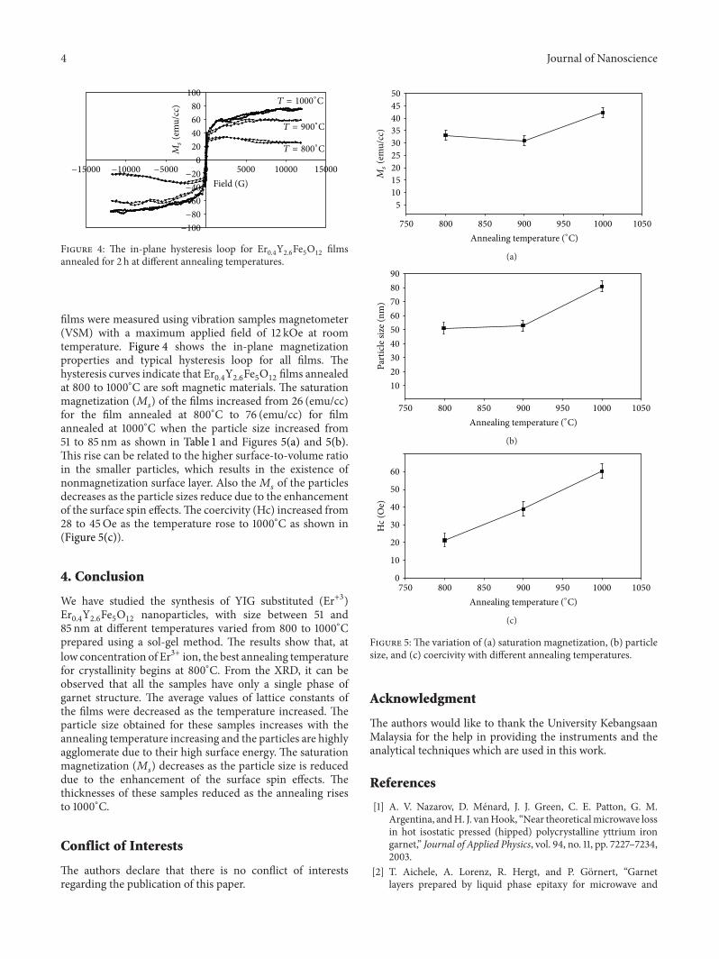
Figure 4: The in-plane hysteresis loop for Er0.4Y2.6Fe5O12
filmsannealed for 2 h at different annealing temperatures.
films were measured using vibration samples magnetometer(VSM) with a maximum applied field of 12 kOe at roomtemperature. Figure 4 shows the in-plane magnetizationproperties and typical hysteresis loop for all films. Thehysteresis curves indicate that Er
0.4Y2.6Fe5O12films annealed
at 800 to 1000∘C are soft magnetic materials. The saturationmagnetization (𝑀
𝑠) of the films increased from 26 (emu/cc)
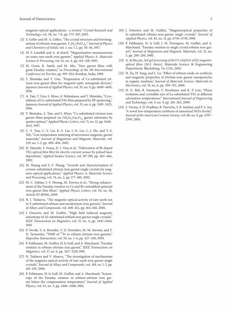
for the film annealed at 800∘C to 76 (emu/cc) for filmannealed at 1000∘C when the particle size increased from51 to 85 nm as shown in Table 1 and Figures 5(a) and 5(b).This rise can be related to the higher surface-to-volume ratioin the smaller particles, which results in the existence ofnonmagnetization surface layer. Also the𝑀
𝑠of the particles
decreases as the particle sizes reduce due to the enhancementof the surface spin effects.The coercivity (Hc) increased from28 to 45Oe as the temperature rose to 1000∘C as shown in(Figure 5(c)).
4. Conclusion
We have studied the synthesis of YIG substituted (Er+3)Er0.4Y2.6Fe5O12
nanoparticles, with size between 51 and85 nm at different temperatures varied from 800 to 1000∘Cprepared using a sol-gel method. The results show that, atlow concentration of Er3+ ion, the best annealing temperaturefor crystallinity begins at 800∘C. From the XRD, it can beobserved that all the samples have only a single phase ofgarnet structure. The average values of lattice constants ofthe films were decreased as the temperature increased. Theparticle size obtained for these samples increases with theannealing temperature increasing and the particles are highlyagglomerate due to their high surface energy. The saturationmagnetization (𝑀
𝑠) decreases as the particle size is reduced
due to the enhancement of the surface spin effects. Thethicknesses of these samples reduced as the annealing risesto 1000∘C.
Conflict of Interests
The authors declare that there is no conflict of interestsregarding the publication of this paper.
50
45
40
35
30
25
20
15
10
5
Ms
(em
u/cc
)
750 800 850 900 950 1000 1050
Annealing temperature (∘C)
(a)
90
80
70
60
50
40
30
20
10Pa
rtic
le si
ze (n
m)
750 800 850 900 950 1000 1050
Annealing temperature (∘C)
(b)
60
50
40
30
20
10
0
Hc (
Oe)
750 800 850 900 950 1000 1050
Annealing temperature (∘C)
(c)
Figure 5: The variation of (a) saturation magnetization, (b) particlesize, and (c) coercivity with different annealing temperatures.
Acknowledgment
The authors would like to thank the University KebangsaanMalaysia for the help in providing the instruments and theanalytical techniques which are used in this work.
References
[1] A. V. Nazarov, D. Menard, J. J. Green, C. E. Patton, G. M.Argentina, andH. J. vanHook, “Near theoreticalmicrowave lossin hot isostatic pressed (hipped) polycrystalline yttrium irongarnet,” Journal of Applied Physics, vol. 94, no. 11, pp. 7227–7234,2003.
[2] T. Aichele, A. Lorenz, R. Hergt, and P. Gornert, “Garnetlayers prepared by liquid phase epitaxy for microwave and
Journal of Nanoscience 5
magneto-optical applications—a review,” Crystal Research andTechnology, vol. 38, no. 7-8, pp. 575–587, 2003.
[3] S. Geller and M. A. Gilleo, “The crystal structure and ferrimag-netism of yttrium-iron garnet, Y
3Fe2(FeO4)3,” Journal of Physics
and Chemistry of Solids, vol. 3, no. 1-2, pp. 30–36, 1957.[4] M. S. Lataifeh and A. al-sharif, “Magnetization measurements
on some rare-earth iron garnets,” Applied Physics A: MaterialsScience & Processing, vol. 61, no. 4, pp. 415–418, 1995.
[5] M. Gomi, K. Satoh, and M. Abe, “New garnet films withgiant Faraday rotation,” in Proceedings of the 5th InternationalConference on Ferrites, pp. 919–924, Bombay, India, 1989.
[6] T. Shintaku and T. Uno, “Preparation of Ce-substituted ytt-rium iron garnet films for magneto-optic waveguide devices,”Japanese Journal of Applied Physics, vol. 35, no. 9, pp. 4689–4691,1996.
[7] A. Tate, T. Uno, S. Mino, A. Shibukawa, and T. Shintaku, “Crys-tallinity of Ce-substituted YIGfilms prepared by RF sputtering,”Japanese Journal of Applied Physics, vol. 35, no. 6, pp. 3419–3425,1996.
[8] T. Shintaku, A. Tate, and S. Mino, “Ce-substituted yttrium irongarnet films prepared on Gd
3Sc2Ga3O12
garnet substrates bysputter epitaxy,”Applied Physics Letters, vol. 71, no. 12, pp. 1640–1642, 1997.
[9] C.-Y. Tsay, C.-Y. Liu, K.-S. Liu, I.-N. Lin, L.-J. Hu, and T.-S.Yeh, “Low temperature sintering of microwave magnetic garnetmaterials,” Journal of Magnetism and Magnetic Materials, vol.239, no. 1–3, pp. 490–494, 2002.
[10] H. Hayashi, S. Iwasa, N. J. Vasa et al., “Fabrication of Bi-dopedYIG optical thin film for electric current sensor by pulsed laserdeposition,” Applied Surface Science, vol. 197-198, pp. 463–466,2002.
[11] M. Huang and S.-Y. Zhang, “Growth and characterization ofcerium-substituted yttrium iron garnet single crystals for mag-neto-optical applications,” Applied Physics A: Materials Scienceand Processing, vol. 74, no. 2, pp. 177–180, 2002.
[12] M. C. Sekhar, J.-Y. Hwang, M. Ferrera et al., “Strong enhance-ment of the Faraday rotation in Ce and Bi comodified epitaxialiron garnet thin films,” Applied Physics Letters, vol. 94, no. 18,Article ID 181916, 2009.
[13] N. I. Tsidaeva, “The magneto-optical activity of rare-earth ionin Y-substituted erbium and neodymium iron garnets,” Journalof Alloys and Compounds, vol. 408–412, pp. 164–168, 2006.
[14] J. Ostorero and M. Guillot, “High field induced magneticanisotropy of Al-substituted erbium iron garnet single crystals,”IEEE Transactions on Magnetics, vol. 37, no. 4, pp. 2441–2444,2001.
[15] P. Novak, V. A. Borodin, V. D. Doroshev, M. M. Savosta, and T.N. Tarasenko, “NMR of 57Fe in erbium-yttrium iron garnets,”Hyperfine Interactions, vol. 59, no. 1–4, pp. 427–430, 1990.
[16] P. Feldmann, M. Guillot, H. le Gall, and A. Marchand, “Faradayrotation in erbium-yttrium iron garnet,” IEEE Transactions onMagnetics, vol. 17, no. 6, pp. 3217–3219, 1981.
[17] N. Tsidaeva and V. Abaeva, “The investigation of mechanismsof the magneto-optical activity of rare-earth iron garnet singlecrystals,” Journal of Alloys and Compounds, vol. 418, no. 1-2, pp.145–150, 2006.
[18] P. Feldmann, H. le Gall, M. Guillot, and A. Marchand, “Anisot-ropy of the Faraday rotation in erbium-yttrium iron gar-net below the compensation temperature,” Journal of AppliedPhysics, vol. 53, no. 3, pp. 2486–2488, 1982.
[19] J. Ostorero and M. Guillot, “Magnetooptical properties ofSc-substituted erbium-iron-garnet single crystals,” Journal ofApplied Physics, vol. 83, no. 11, pp. 6756–6758, 1998.
[20] P. Feldmann, H. le Gall, J. M. Desvignes, M. Guillot, and A.Marchand, “Faraday rotation in single crystal erbium iron gar-net,” Journal of Magnetism and Magnetic Materials, vol. 21, no.3, pp. 280–284, 1980.
[21] A. di Biccari, Sol-gel processing of RxY3-xAlyFe5-yO12 magneto-optical films [M.S. thesis], Materials Science & EngineeringDepartment, Blacksburg, Va, USA, 2002.
[22] H. Xu, H. Yang, and L. Lu, “Effect of erbium oxide on synthesisand magnetic properties of yttrium-iron garnet nanoparticlesin organic medium,” Journal of Materials Science: Materials inElectronics, vol. 19, no. 6, pp. 509–513, 2008.
[23] H. G. Beh, R. Irmawati, Y. Noorhana, and K. P. Lim, “Phaseevolution and crystallite size of La-substituted YIG at differentcalcination temperatures,” International Journal of Engineeringand Technology, vol. 9, no. 9, pp. 261–265, 2009.
[24] S. Verma, S. D. Pradhan, R. Pasricha, S. R. Sainkar, and P. A. Joy,“A novel low-temperature synthesis of nanosized NiZn ferrite,”Journal of the American Ceramic Society, vol. 88, no. 9, pp. 2597–2599, 2005.

Submit your manuscripts athttp://www.hindawi.com
ScientificaHindawi Publishing Corporationhttp://www.hindawi.com Volume 2014
CorrosionInternational Journal of
Hindawi Publishing Corporationhttp://www.hindawi.com Volume 2014
Polymer ScienceInternational Journal of
Hindawi Publishing Corporationhttp://www.hindawi.com Volume 2014
Hindawi Publishing Corporationhttp://www.hindawi.com Volume 2014
CeramicsJournal of
Hindawi Publishing Corporationhttp://www.hindawi.com Volume 2014
CompositesJournal of
NanoparticlesJournal of
Hindawi Publishing Corporationhttp://www.hindawi.com Volume 2014
Hindawi Publishing Corporationhttp://www.hindawi.com Volume 2014
International Journal of
Biomaterials
Hindawi Publishing Corporationhttp://www.hindawi.com Volume 2014
NanoscienceJournal of
TextilesHindawi Publishing Corporation http://www.hindawi.com Volume 2014
Journal of
NanotechnologyHindawi Publishing Corporationhttp://www.hindawi.com Volume 2014
Journal of
CrystallographyJournal of
Hindawi Publishing Corporationhttp://www.hindawi.com Volume 2014
The Scientific World JournalHindawi Publishing Corporation http://www.hindawi.com Volume 2014
Hindawi Publishing Corporationhttp://www.hindawi.com Volume 2014
CoatingsJournal of
Advances in
Materials Science and EngineeringHindawi Publishing Corporationhttp://www.hindawi.com Volume 2014
Smart Materials Research
Hindawi Publishing Corporationhttp://www.hindawi.com Volume 2014
Hindawi Publishing Corporationhttp://www.hindawi.com Volume 2014
MetallurgyJournal of
Hindawi Publishing Corporationhttp://www.hindawi.com Volume 2014
BioMed Research International
MaterialsJournal of
Hindawi Publishing Corporationhttp://www.hindawi.com Volume 2014
Nano
materials
Hindawi Publishing Corporationhttp://www.hindawi.com Volume 2014
Journal ofNanomaterials