Embed Size (px)
Citation preview
A scalable helium gas cooling system for trapped-ion applications
A scalable helium gas cooling system for trapped-ion applicationsF. R. Lebrun-Gallagher,1 N. Johnson,1 M. Akhtar,1, 2 S. Weidt,1, 2 D. Bretaud,1, 3 S. J. Hile,1 A. Owens,1 and W.K. Hensinger1, 2, a)1)Sussex Centre for Quantum Technologies, University of Sussex, Brighton, BN1 9RH,U.K.2)Universal Quantum Ltd, Brighton, BN1 6SB, U.K.3)QOLS, Blackett Laboratory, Imperial College London, London, SW7 2BW, U.K.
(Dated: 15 June 2021)
Microfabricated ion-trap devices offer a promising pathway towards scalable quantum computing. Research effortshave begun to focus on the engineering challenges associated with developing large-scale ion-trap arrays and networks.However, increasing the size of the array and integrating on-chip electronics can drastically increase the power dissipa-tion within the ion-trap chips. This leads to an increase in the operating temperature of the ion-trap and limits the deviceperformance. Therefore, effective thermal management is an essential consideration for any large-scale architecture.Presented here is the development of a modular cooling system designed for use with multiple ion-trapping experi-ments simultaneously. The system includes an extensible cryostat that permits scaling of the cooling power to meetthe demands of a large network. Following experimental testing on two independent ion-trap experiments, the coolingsystem is expected to deliver a net cooling power of 111 W at ∼70 K to up to four experiments. The cooling system isa step towards meeting the practical challenges of operating large-scale quantum computers with many qubits.
I. INTRODUCTION
Trapped ions are a leading platform for quantum com-puters (QCs)1, quantum simulators2, high-precision quantumsensors3,4 and fundamental physics research5,6. A number oftrapped-ion QC architectures have been proposed which fo-cus on developing scalable designs for future fault-tolerantdevices with many qubits7,8. Microfabricated ion-traps9 area promising architecture for a modular QC7. A recently pub-lished QC blueprint7 uses modular surface ion-traps, with in-tegrated on-chip electronics for ion transport, quantum statemanipulation and readout. Each addition of these on-chip fea-tures, however, increases the power dissipated by componentssuch as radio frequency (RF) conductors, digital-to-analogueconverters (DACs), fluorescence detectors, integrated ovens,and magnetic field generating structures. The thermal man-agement of the modular QC is then essential to retain a rea-sonable operating temperature and also to improve ion-trapperformance10. Operation at cryogenic temperatures sup-presses electric field noise10, leading to a reduction in ion mo-tional heating11 and significantly improves trapping lifetimes,qubit coherence times and quantum logic gate fidelities12.
When considering a target operating temperature for an ion-trap, one of the primary concerns is the motional heating rateof the ion. Motional heating is driven by electric field fluctu-ations within the surface layers of a chip12. The ion motionalheating rate n follows a temperature dependency of the form12
n ∝ 1+(
TT0
)β
, (1)
where T0 is the thermal activation temperature, found to be inthe 10–75 K temperature range10,12, T is the temperature of
a)Electronic mail: [email protected]
the ion-trap and β is an exponent describing the high temper-ature dependency, typically in the 1.5–4.1 range10,11. This in-dicates that cooling below the thermal activation temperatureaffords only a marginal reduction in the ion motional heatingrate. In practice most of the gains are made when cooling from300 K to 100 K, leading to a heating rate reduction of severalorders of magnitude10,12,13.
Operation at temperatures below 100 K still may be desir-able, since it decreases the vacuum pressure and therefore re-duces the probability of background gas molecules collidingwith the ion. For example, systems operating at 4 K havelower vacuum pressures by about 4 orders of magnitude whencompared to the typical vacuum pressure of room-temperatureexperiments14. However, operation at 4 K presents severaltechnical challenges, such as with implementing silicon-basedelectronics15,16.
This paper describes the development of a scalable coolingsystem with novel application to ion-trap devices and otherhigh power experiments. Designed as a step towards a scal-able cryogenic cooling solution suited to the QC architecturedescribed by Lekitsch et al.7, the system uses circulating he-lium gas to cool multiple ion-trapping experiments indepen-dently to below 70 K.
II. DESIGN OVERVIEW
A range of cryogenic cooling solutions have been demon-strated with small-scale ion-trapping experiments. ‘Wet’ sys-tems consist of either an open bath13,17,18 or an open con-tinuous flow cryostat14 that use 4 K liquid helium or 77 Kliquid nitrogen as coolant. Cryogenic temperatures are sus-tained for the duration of the liquid cryogen reserve which islost to the environment by evaporation. ‘Dry’ cryogenic sys-tems do not require replenishment of cryogen, which is anattractive feature. Instead, cooling is provided by a closedcryogen-free refrigeration cycle. These have found wide ap-plication to ion trapping experiments in the form of Pulse-
arX
iv:2
106.
0758
0v1
[qu
ant-
ph]
14
Jun
2021
A scalable helium gas cooling system for trapped-ion applications 2
Cryostat
Cryocooler 1 Cryocooler 2
PRVHe flush
Exp 1 inlet
Exp 1outlet
Exp 1
Heat sink
Water-cooledcompressor
Heater
Exp 2
Heat sink
Heater
He relief
He fill
Water-cooledcompressor
PRVHe flush
Exp 2 inlet
Exp 2outlet
Flexible VJ lines
Vacuum insulated transfer lines
Low thermal conductivity support
Merge inlet
Merge outlet
T8
T10T9
T12T11
Heat exchangerCryofan
Valve
Pt100
Si diode sensor
T2
T3
T1
T6
T4T5
T7
Heat exchanger
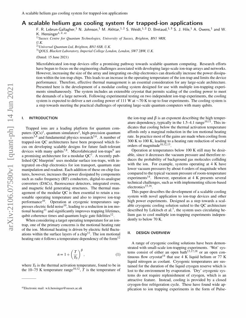
FIG. 1. Schematic overview of the cryogenic cooling system. Cryocooler 1 (Gifford-McMahon CH110) and cryocooler 2 (Gifford-McMahonAL330) are remotely connected to two ion-trap experiments: ‘Exp 1’ and ‘Exp 2’. Not shown are the lines that can be used to connect twofurther experiments in parallel at the merge inlet and merge outlet points (in a similar fashion to Exp 2.). At these points, the division of thehelium gas flow is controlled by the manual cryogenic valves allocated to each experiments. The in-vacuum support structure that is usedfor Exp 1 is detailed within the text. The Pt100 sensor T1 and the silicon diode sensor T2 are fitted to the cold finger of cryocooler 1 and 2respectively and are selected to best match the thermal performance of each cryocooler.
Tube19,20 or Gifford-McMahon (GM)21,22 cryocoolers. How-ever, size constraints prevent sufficient numbers of individual,commercially available cryostats from being used togetherwithin closely-spaced ion-trap arrays. Therefore, a new cool-ing architecture that avoids these constraints is proposed. Thearchitecture is based on a closed-loop cryogenic helium gascirculation system; separating the cryocooler from the ion-traps in a way which is in principle extensible to accommo-date large numbers of both ion-trap elements and cryocoolercold-heads.
A cooling system based on this architecture was con-structed to interface between four independent ion-trap ex-periments. The cooling system consists of three sections: amain cryostat chamber that houses two single-stage Gifford-McMahon cryocooler cold heads and a centrifugal fan; a net-work of vacuum-jacketed (VJ) helium transfer lines that dis-tribute the cold gas from the cryostat to the ion-trap exper-iments, and a cryogenic heat sink installed on each experi-ment. A diagram of the cooling system is shown in Figure 1.The cooling system distributes helium gas to multiple exper-iments configured in parallel. Individual experiments can beconnected and disconnected from the cooling circuit indepen-dently. Together, the two cryocoolers deliver a total cooling
power of 396 W at 80 K23,24.
Inside the cryostat chamber, each cold head interfaceswith a heat exchanger, which is braised to the stainless steelfeedthroughs carrying helium gas. This minimises the thermalresistance between the cold head and the helium cryogen. Thecompressors used to operate the cryocoolers are located in aseparate room next to the laboratory to minimise vibration atthe ion-trap experiments.
Helium gas is circulated using a Stirling Cryogenics Noor-denwind centrifugal fan (or ‘cryofan’). The flow of heliumgas is routed to the two cold heads in parallel and then re-combined prior to the inlet of the cryofan. This parallel cir-cuit configuration reduces the overall flow resistance acrossthe cryostat section, while allowing for faster thermalisationof the gas through the heat exchangers. In this configurationthe total available cooling power can be scaled by integrat-ing extra cryocoolers in parallel. Within the cryostat vessel,leak-tight connections are made using both vacuum couplingradiation (VCR) fittings and by direct welding. To assist indampening vibrations caused by the cryocooler, a section offlexible, mesh-reinforced, stainless steel braided hose was in-stalled at the cryofan inlet.
The cryostat vessel and the VJ lines are maintained under
A scalable helium gas cooling system for trapped-ion applications 3
vacuum (< 10−4 mbar) to prevent conductive heat leaks. Thecold heads, cryofan and stainless-steel tubing are lined with30 layers of multilayer insulation (MLI) to minimise radiativeheat leaks. Overall, the transfer lines are expected to con-tribute to thermal losses by ∼0.2 W/m across the network,which extends for ∼30 m.
At the locations of each ion-trapping experiment, the VJtransfer lines separate into two individual supply and returnlines. These are constructed from flexible VJ tubing to fur-ther attenuate vibrations from the cryostat and correct for ther-mal expansion mismatches between sections of different tem-peratures. Cryogenic vacuum barriers are fitted between themain rigid VJ line and the flexible sections, and on the heliumfeedthroughs of the ion-trap vacuum chamber. This allowsfor the flexible sections to be disconnected from the vacuumchamber, while maintaining the vacuum insulation within themain VJ transfer line and the UHV (ultra-high vacuum) withinthe ion-trap experiment.
The system is pressurised to 20 bar and the overall heliumgas mass flow rate is controlled by adjusting the rotation speedof the cryofan impeller which can be throttled between 6,000and 21,000 revolutions per minute (rpm). A schematic of thehelium gas transfer network, which connects the cryostat tothe ion-trap experiments, is shown in Figure 1.
The local flow of helium gas allocated to each ion-trappingexperiment is regulated using two manual cryogenic valveswhich are fitted on the feed and return transfer lines. When anexperiment is disconnected, the cold pressurised helium gastrapped in the experiment heat sink warms up and expands. Acryogenic safety pressure release valve (PRV), set to 23 bar, isfitted at the experiment return VJ line to avoid over-pressure inthe heat sink during thermalisation to room temperature. Anadditional valve (‘He flush’ valve in Figure 1) connects theinner helium line to atmosphere and allows for each experi-ment to be evacuated and flushed with helium before beingcooled down. Flushing with helium removes any trapped airand water vapour that can freeze on the impeller blades of thecryofan, or inside the heat sink, which may cause damage orchoke the helium flow.
III. INTERFACING WITH AN ION -TRAP EXPERIMENT
In each ion-trap experiment, active heat loads arise fromvarious sources, e.g. RF losses within the substrate of themicrochips, Ohmic heating within microfabricated wires car-rying electrical currents7,25, and power dissipation from chip-integrated electronics26. Passive heat loads result from boththermal conduction and radiation. Conductive losses occuralong solid paths provided by feedthrough connections intothe vacuum chamber and by the in-vacuum mounting struc-ture. Radiative heat transfer occurs between the room temper-ature vacuum apparatus and the cryogenic surfaces that are indirect line of sight.
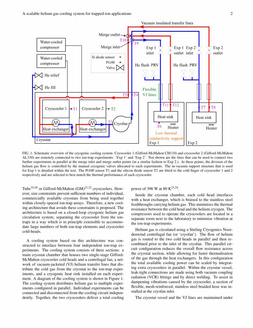
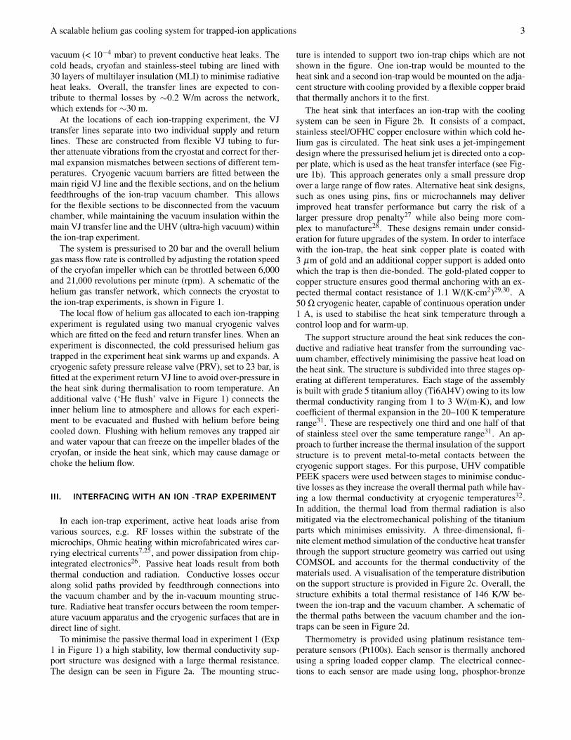
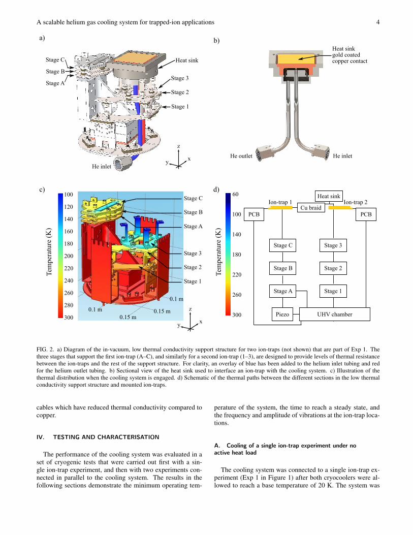
To minimise the passive thermal load in experiment 1 (Exp1 in Figure 1) a high stability, low thermal conductivity sup-port structure was designed with a large thermal resistance.The design can be seen in Figure 2a. The mounting struc-
ture is intended to support two ion-trap chips which are notshown in the figure. One ion-trap would be mounted to theheat sink and a second ion-trap would be mounted on the adja-cent structure with cooling provided by a flexible copper braidthat thermally anchors it to the first.
The heat sink that interfaces an ion-trap with the coolingsystem can be seen in Figure 2b. It consists of a compact,stainless steel/OFHC copper enclosure within which cold he-lium gas is circulated. The heat sink uses a jet-impingementdesign where the pressurised helium jet is directed onto a cop-per plate, which is used as the heat transfer interface (see Fig-ure 1b). This approach generates only a small pressure dropover a large range of flow rates. Alternative heat sink designs,such as ones using pins, fins or microchannels may deliverimproved heat transfer performance but carry the risk of alarger pressure drop penalty27 while also being more com-plex to manufacture28. These designs remain under consid-eration for future upgrades of the system. In order to interfacewith the ion-trap, the heat sink copper plate is coated with3 µm of gold and an additional copper support is added ontowhich the trap is then die-bonded. The gold-plated copper tocopper structure ensures good thermal anchoring with an ex-pected thermal contact resistance of 1.1 W/(K·cm2)29,30. A50 Ω cryogenic heater, capable of continuous operation under1 A, is used to stabilise the heat sink temperature through acontrol loop and for warm-up.
The support structure around the heat sink reduces the con-ductive and radiative heat transfer from the surrounding vac-uum chamber, effectively minimising the passive heat load onthe heat sink. The structure is subdivided into three stages op-erating at different temperatures. Each stage of the assemblyis built with grade 5 titanium alloy (Ti6Al4V) owing to its lowthermal conductivity ranging from 1 to 3 W/(m·K), and lowcoefficient of thermal expansion in the 20–100 K temperaturerange31. These are respectively one third and one half of thatof stainless steel over the same temperature range31. An ap-proach to further increase the thermal insulation of the supportstructure is to prevent metal-to-metal contacts between thecryogenic support stages. For this purpose, UHV compatiblePEEK spacers were used between stages to minimise conduc-tive losses as they increase the overall thermal path while hav-ing a low thermal conductivity at cryogenic temperatures32.In addition, the thermal load from thermal radiation is alsomitigated via the electromechanical polishing of the titaniumparts which minimises emissivity. A three-dimensional, fi-nite element method simulation of the conductive heat transferthrough the support structure geometry was carried out usingCOMSOL and accounts for the thermal conductivity of thematerials used. A visualisation of the temperature distributionon the support structure is provided in Figure 2c. Overall, thestructure exhibits a total thermal resistance of 146 K/W be-tween the ion-trap and the vacuum chamber. A schematic ofthe thermal paths between the vacuum chamber and the ion-traps can be seen in Figure 2d.
Thermometry is provided using platinum resistance tem-perature sensors (Pt100s). Each sensor is thermally anchoredusing a spring loaded copper clamp. The electrical connec-tions to each sensor are made using long, phosphor-bronze
A scalable helium gas cooling system for trapped-ion applications 4
a) b)
Heat sink
He inlet
Heat sinkgold coated copper contact
He outlet He inlet
Stage 1
Stage 2
Stage 3
Tem
pera
ture
(K
)
0.15 m0.15 m
0.1 m
c)
0.1 m
d)
Stage A
Stage B
Stage C
PCB
Stage A
Stage B
Stage C
Stage 1
Stage 2
Stage 3
Heat sink
Piezo UHV chamber
PCB
Ion-trap 1 Ion-trap 2Cu braid
300
280
260
240
220
200
180
160
140
120
100 60
300
260
220
180
140
100
Stage C
Stage B
Stage A
Stage 1
Stage 2
Stage 3
Tem
pera
ture
(K
)
xy
z
xy
z
FIG. 2. a) Diagram of the in-vacuum, low thermal conductivity support structure for two ion-traps (not shown) that are part of Exp 1. Thethree stages that support the first ion-trap (A–C), and similarly for a second ion-trap (1–3), are designed to provide levels of thermal resistancebetween the ion-traps and the rest of the support structure. For clarity, an overlay of blue has been added to the helium inlet tubing and redfor the helium outlet tubing. b) Sectional view of the heat sink used to interface an ion-trap with the cooling system. c) Illustration of thethermal distribution when the cooling system is engaged. d) Schematic of the thermal paths between the different sections in the low thermalconductivity support structure and mounted ion-traps.
cables which have reduced thermal conductivity compared tocopper.
IV. TESTING AND CHARACTERISATION
The performance of the cooling system was evaluated in aset of cryogenic tests that were carried out first with a sin-gle ion-trap experiment, and then with two experiments con-nected in parallel to the cooling system. The results in thefollowing sections demonstrate the minimum operating tem-
perature of the system, the time to reach a steady state, andthe frequency and amplitude of vibrations at the ion-trap loca-tions.
A. Cooling of a single ion-trap experiment under noactive heat load
The cooling system was connected to a single ion-trap ex-periment (Exp 1 in Figure 1) after both cryocoolers were al-lowed to reach a base temperature of 20 K. The system was
A scalable helium gas cooling system for trapped-ion applications 5
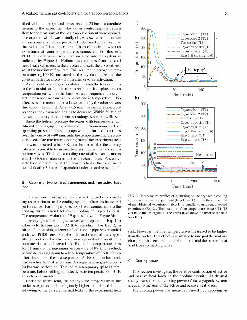
filled with helium gas and pressurised to 20 bar. To circulatehelium to the experiment, the valves controlling the heliumflow to the heat sink at the ion-trap experiment were opened.The cryofan, which was initially off, was switched on and setat its maximum rotation speed of 21,000 rpm. Figure 3a showsthe evolution of the temperature of the cooling circuit when anexperiment at room-temperature is connected. For this test,Pt100 temperature sensors were installed into the system asindicated by Figure 1. Helium gas circulates from the coldhead heat exchangers to the cryofan and exits the cryostat ves-sel at the maximum flow rate. This resulted in cryogenic tem-peratures (≤100 K) measured at the cryofan intake and thecryostat outlet locations ∼5 min after cryofan activation.
As the cold helium gas circulates through the transfer linesto the heat sink at the ion-trap experiment, it displaces roomtemperature gas within the lines. As a consequence, the cryo-stat inlet sensor measures a transient rise in temperature. Thiseffect was also measured to a lesser extent by the other sensorsthroughout the circuit. After ∼15 min, the rising temperaturereaches a maximum and begins to decrease. Within 30 min ofactivating the cryofan, all sensor readings were below 40 K.
Since the helium pressure decreases with temperature, ad-ditional ‘topping-up’ of gas was required to maintain a 20 baroperating pressure. These top-ups were performed four timesover the course of ∼90 min, until the temperature and pressurestabilised. The maximum cooling rate at the experiment heatsink was measured to be 23 K/min. Full control of the coolingrate is also possible by manually adjusting the inlet and returnhelium valves. The highest cooling rate of all sensor locationswas 150 K/min, measured at the cryofan intake. A steady-state base temperature of 32 K was reached at the experimentheat sink after 3 hours of operation under no active heat load.
B. Cooling of two ion-trap experiments under no active heatload
This section investigates how connecting and disconnect-ing an experiment to the cooling system influences its overallperformance. For this purpose, Exp 1 was connected into thecooling system circuit following cooling of Exp 2 to 32 K.The temperature evolution of Exp 1 is shown in Figure 3b.
The cryogenic helium gas valves were opened at Exp 1 toallow cold helium gas at 32 K to circulate. For Exp 2, inplace of a heat sink, a length of 1⁄4 " copper pipe was installedwith two Pt100 sensors at the inlet and outlet of the copperfitting. As the valves to Exp 1 were opened a transient tem-perature rise was observed. At Exp 2 the temperature risesfor 11 min until a maximum temperature of 97 K is reached,before decreasing again to a base temperature of 36 K 60 minafter the start of the test sequence. At Exp 1, the heat sinkalso reaches 36 K after 60 min. A single helium gas top-up to20 bar was performed. This led to a temporary spike in tem-perature, before settling to a steady state temperature of 34 Kat both experiments.
Under no active load, the steady-state temperature at theoutlet is expected to be marginally higher than that of the in-let owing to the passive thermal leaks to the experiment heat
b)
a)
He 'top up'
He 'top up'
FIG. 3. Temperature profiles of a) turning on the cryogenic coolingsystem with a single experiment (Exp 1) and b) during the connectionof an additional experiment (Exp 1) in parallel to an already cooledexperiment (Exp 2). The locations of the temperature sensors T1–T8can be found on Figure 1. The graph inset shows a subset of the datafor clarity.
sink. However, the inlet temperature is measured to be higherthan the outlet. This effect is attributed to unequal thermal an-choring of the sensors to the helium lines and the passive heatload from connecting wires.
C. Cooling power
This section investigates the relative contribution of activeand passive heat loads in the cooling circuit. At thermalsteady-state, the total cooling power of the cryogenic systemis equal to the sum of the active and passive heat loads.
The cooling power was measured directly by applying an
A scalable helium gas cooling system for trapped-ion applications 6
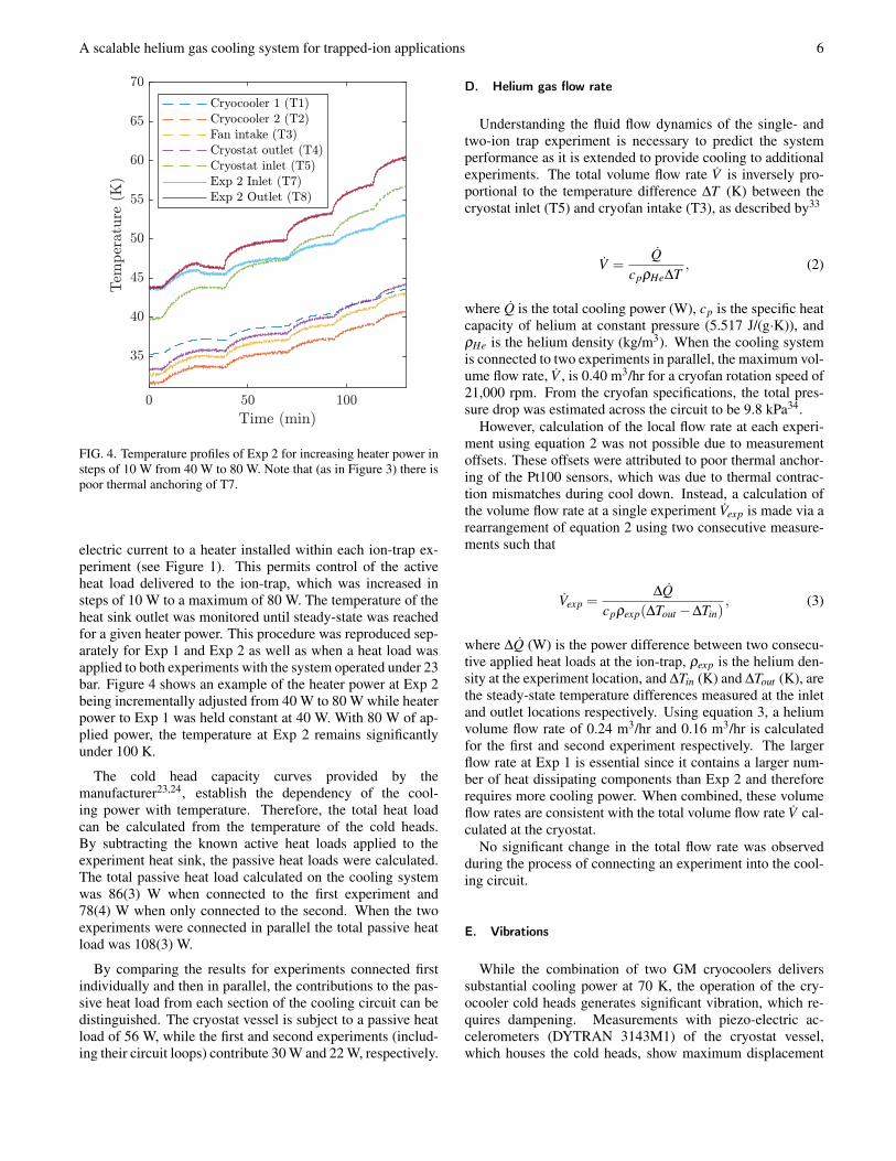
FIG. 4. Temperature profiles of Exp 2 for increasing heater power insteps of 10 W from 40 W to 80 W. Note that (as in Figure 3) there ispoor thermal anchoring of T7.
electric current to a heater installed within each ion-trap ex-periment (see Figure 1). This permits control of the activeheat load delivered to the ion-trap, which was increased insteps of 10 W to a maximum of 80 W. The temperature of theheat sink outlet was monitored until steady-state was reachedfor a given heater power. This procedure was reproduced sep-arately for Exp 1 and Exp 2 as well as when a heat load wasapplied to both experiments with the system operated under 23bar. Figure 4 shows an example of the heater power at Exp 2being incrementally adjusted from 40 W to 80 W while heaterpower to Exp 1 was held constant at 40 W. With 80 W of ap-plied power, the temperature at Exp 2 remains significantlyunder 100 K.
The cold head capacity curves provided by themanufacturer23,24, establish the dependency of the cool-ing power with temperature. Therefore, the total heat loadcan be calculated from the temperature of the cold heads.By subtracting the known active heat loads applied to theexperiment heat sink, the passive heat loads were calculated.The total passive heat load calculated on the cooling systemwas 86(3) W when connected to the first experiment and78(4) W when only connected to the second. When the twoexperiments were connected in parallel the total passive heatload was 108(3) W.
By comparing the results for experiments connected firstindividually and then in parallel, the contributions to the pas-sive heat load from each section of the cooling circuit can bedistinguished. The cryostat vessel is subject to a passive heatload of 56 W, while the first and second experiments (includ-ing their circuit loops) contribute 30 W and 22 W, respectively.
D. Helium gas flow rate
Understanding the fluid flow dynamics of the single- andtwo-ion trap experiment is necessary to predict the systemperformance as it is extended to provide cooling to additionalexperiments. The total volume flow rate V is inversely pro-portional to the temperature difference ∆T (K) between thecryostat inlet (T5) and cryofan intake (T3), as described by33
V =Q
cpρHe∆T, (2)
where Q is the total cooling power (W), cp is the specific heatcapacity of helium at constant pressure (5.517 J/(g·K)), andρHe is the helium density (kg/m3). When the cooling systemis connected to two experiments in parallel, the maximum vol-ume flow rate, V , is 0.40 m3/hr for a cryofan rotation speed of21,000 rpm. From the cryofan specifications, the total pres-sure drop was estimated across the circuit to be 9.8 kPa34.
However, calculation of the local flow rate at each experi-ment using equation 2 was not possible due to measurementoffsets. These offsets were attributed to poor thermal anchor-ing of the Pt100 sensors, which was due to thermal contrac-tion mismatches during cool down. Instead, a calculation ofthe volume flow rate at a single experiment Vexp is made via arearrangement of equation 2 using two consecutive measure-ments such that
Vexp =∆Q
cpρexp(∆Tout −∆Tin), (3)
where ∆Q (W) is the power difference between two consecu-tive applied heat loads at the ion-trap, ρexp is the helium den-sity at the experiment location, and ∆Tin (K) and ∆Tout (K), arethe steady-state temperature differences measured at the inletand outlet locations respectively. Using equation 3, a heliumvolume flow rate of 0.24 m3/hr and 0.16 m3/hr is calculatedfor the first and second experiment respectively. The largerflow rate at Exp 1 is essential since it contains a larger num-ber of heat dissipating components than Exp 2 and thereforerequires more cooling power. When combined, these volumeflow rates are consistent with the total volume flow rate V cal-culated at the cryostat.
No significant change in the total flow rate was observedduring the process of connecting an experiment into the cool-ing circuit.
E. Vibrations
While the combination of two GM cryocoolers deliverssubstantial cooling power at 70 K, the operation of the cry-ocooler cold heads generates significant vibration, which re-quires dampening. Measurements with piezo-electric ac-celerometers (DYTRAN 3143M1) of the cryostat vessel,which houses the cold heads, show maximum displacement
A scalable helium gas cooling system for trapped-ion applications 7
b)
a)
c)
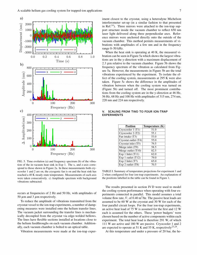
FIG. 5. Time evolution (a) and frequency spectrum (b) of the vibra-tion of the in-vacuum heat sink in Exp 1. The x, and z-axis corre-spond to those shown in Figure 2a. In these measurements both cry-ocooler 1 and 2 are on, the cryogenic fan is on and the heat sink hasreached a 40 K steady-state temperature. Measurements of each axiswere taken consecutively. c) Amplitude spectrum with backgroundvibrations subtracted.
occurs at frequencies of 2 Hz and 50 Hz, with amplitudes of50 µm and 3 µm respectively.
To reduce the amplitude of vibrations transmitted from thecryostat vessel to the ion-trap experiments, a number of damp-ening measures were installed onto the helium transfer lines.The vacuum jacket surrounding the transfer lines is mechan-ically decoupled from the cryostat via edge-welded bellows.The lines have flexible sections installed at locations close tothe helium feedthroughs on each vacuum chamber. Addition-ally, each vacuum chamber is bolted to an optical table.
Vibration measurements were made at the ion-trap exper-
iment closest to the cryostat, using a heterodyne Michelsoninterferometer set-up (in a similar fashion to that presentedin Ref.14). Three mirrors were attached to the ion-trap sup-port structure inside the vacuum chamber to reflect 650 nmlaser light delivered along three perpendicular axes. Refer-ence mirrors were anchored directly onto the outside of thevacuum chamber. This method permits measurements of vi-brations with amplitudes of a few nm and in the frequencyrange 0–50 kHz.
When the heat sink is operating at 40 K, the measured vi-bration can be seen in Figure 5a which shows the largest vibra-tions are in the y-direction with a maximum displacement of2.3 µm relative to the vacuum chamber. Figure 5b shows thefrequency spectrum of the vibration as calculated from Fig-ure 5a. However, the measurements in Figure 5b are the totalvibrations experienced by the experiment. To isolate the ef-fect of the cooling system, measurements at 295 K were alsotaken. Figure 5c shows the difference in the amplitudes ofvibration between when the cooling system was turned on(Figure 5b) and turned off. The most prominent contribu-tions from the cooling system are in the y-direction at 46 Hz,56 Hz, 68 Hz and 100 Hz with amplitudes of 315 nm, 274 nm,220 nm and 224 nm respectively.
V. SCALING FROM TWO TO FOUR ION-TRAPEXPERIMENTS
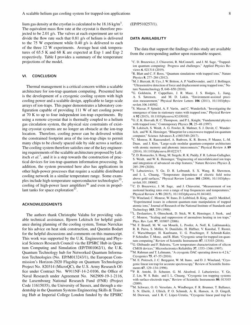
Position Temperature (K)Cryocooler 1 (T1) 51.0Cryocooler 2 (T2) 55.1Fan intake (T3) 53.0Cryostat outlet (T4) 55.0Cryostat inlet (T5) 79.5Merge inlet (T9) 58.5Merge outlet (T10) 82.5Exp 1 Inlet (T11) 62.0Exp 1 outlet (T12) 79.0Exp 2 Inlet (T7) 65.0Exp 2 outlet (T8) 70.5
TABLE I. Summary of temperature projections for experiment 1 and2 when configured for four ion-trap experiments. An explanation ofthe positions labelled in the table can be found in Figure 1.
The results presented in section IV D were used to modelthe cooling system performance when operating with four ex-periments connected in parallel. This model assumes a totalvolume flow rate, V , of 0.40 m3/hr. The passive heat loads areassumed to be 60 W at the cryostat and 30 W for each of thefour parallel circuit loops. For the four ion-trap experiments,an active heat load of 75 W is assumed for the first and 12 Weach is assumed for the others. These ‘power budgets’ werechosen based on the number of active components within eachexperiment. The total heat load is therefore 291 W, of which111 W are active and 180 W are passive. Cryocooler 1 and 2are expected to operate at 51 K and 55 K, respectively23,24.
At this temperature and under a pressure of 20 bar, the he-
A scalable helium gas cooling system for trapped-ion applications 8
lium gas density at the cryofan is calculated to be 18.16 kg/m3.The equivalent mass flow rate at the cryostat is therefore pro-jected to be 2.01 g/s. The valves at each experiment are set todivide the flow rate such that 0.81 g/s of helium is deliveredto the 75 W experiment while 0.40 g/s is delivered to eachof the three 12 W experiments. Average heat sink tempera-tures of 65.5 K and 68 K are expected at Exp 1 and Exp 2respectively. Table I provides a summary of the temperatureprojections of the model.
VI. CONCLUSION
Thermal management is a critical concern within a scalablearchitecture for ion-trap quantum computing. Presented hereis the development of a cryogenic cooling system with highcooling power and a scalable design, applicable to large-scalearrays of ion-traps. This paper demonstrates a laboratory con-figuration capable of providing 111 W of net cooling powerat 70 K to up to four independent ion-trap experiments. Byusing a remote cryostat that is thermally coupled to a heliumgas circulation system, the physical size constraints of exist-ing cryostat systems are no longer an obstacle at the ion-traplocation. Therefore, cooling power can be delivered withinthe constrained footprint area of the ion-trap chips to permitmany chips to be closely spaced side by side across a surface.The cooling system therefore satisfies one of the key engineer-ing requirements of the scalable architecture proposed by Lek-itsch et al.7, and it is a step towards the construction of prac-tical devices for ion-trap quantum information processing. Inaddition, the system presented here also has applications inother high-power processes that require a scalable distributedcooling network in a similar temperature range. Some exam-ples include high-temperature superconductor technologies35,cooling of high-power laser amplifiers36 and even in propel-lant tanks for space exploration37.
ACKNOWLEDGMENTS
The authors thank Christophe Valahu for providing valu-able technical assistance, Bjoern Lekitsch for helpful guid-ance during planning of the cooling system, Tomas Navickasfor his advice on heat sink construction, and Quentin Bodartfor the helpful discussions and comments on this manuscript.This work was supported by the U.K. Engineering and Phys-ical Sciences Research Council via the EPSRC Hub in Quan-tum Computing and Simulation (EP/T001062/1), the U.K.Quantum Technology hub for Networked Quantum Informa-tion Technologies (No. EP/M013243/1), the European Com-mission’s Horizon-2020 Flagship on Quantum TechnologiesProject No. 820314 (MicroQC), the U.S. Army Research Of-fice under Contract No. W911NF-14-2-0106, the Office ofNaval Research under Agreement No. N62909-19-1-2116,the Luxembourg National Research Fund (FNR) (ProjectCode 11615035), the University of Sussex, and through a stu-dentship in the Quantum Systems Engineering Skills & Train-ing Hub at Imperial College London funded by the EPSRC
(EP/P510257/1).
DATA AVAILABILITY
The data that support the findings of this study are availablefrom the corresponding author upon reasonable request.
1C. D. Bruzewicz, J. Chiaverini, R. McConnell, and J. M. Sage, “Trapped-ion quantum computing: Progress and challenges,” Applied Physics Re-views 6, 021314 (2019).
2R. Blatt and C. F. Roos, “Quantum simulations with trapped ions,” NaturePhysics 8, 277–284 (2012).
3M. J. Biercuk, H. Uys, J. W. Britton, A. P. VanDevender, and J. J. Bollinger,“Ultrasensitive detection of force and displacement using trapped ions,” Na-ture Nanotechnology 5, 646–650 (2010).
4G. Goldstein, P. Cappellaro, J. R. Maze, J. S. Hodges, L. Jiang,A. S. Sørensen, and M. D. Lukin, “Environment-assisted preci-sion measurement,” Physical Review Letters 106 (2011), 10.1103/phys-revlett.106.140502.
5S. Massar, P. Spindel, A. F. Varón, and C. Wunderlich, “Investigating theemergence of time in stationary states with trapped ions,” Physical ReviewA 92 (2015), 10.1103/physreva.92.030102.
6G. Z. K. Horvath, R. C. Thompson, and P. L. Knight, “Fundamental physicswith trapped ions,” Contemporary Physics 38, 25–48 (1997).
7B. Lekitsch, S. Weidt, A. G. Fowler, K. Mølmer, S. J. Devitt, C. Wunder-lich, and W. K. Hensinger, “Blueprint for a microwave trapped ion quantumcomputer,” Science Advances 3, e1601540 (2017).
8C. Monroe, R. Raussendorf, A. Ruthven, K. R. Brown, P. Maunz, L.-M.Duan, and J. Kim, “Large-scale modular quantum-computer architecturewith atomic memory and photonic interconnects,” Physical Review A 89(2014), 10.1103/physreva.89.022317.
9Z. D. Romaszko, S. Hong, M. Siegele, R. K. Puddy, F. R. Lebrun-Gallagher,S. Weidt, and W. K. Hensinger, “Engineering of microfabricated ion trapsand integration of advanced on-chip features,” Nature Reviews Physics 2,285–299 (2020).
10J. Labaziewicz, Y. Ge, D. R. Leibrandt, S. X. Wang, R. Shewmon,and I. L. Chuang, “Temperature dependence of electric field noiseabove gold surfaces,” Physical Review Letters 101 (2008), 10.1103/phys-revlett.101.180602.
11C. D. Bruzewicz, J. M. Sage, and J. Chiaverini, “Measurement of ionmotional heating rates over a range of trap frequencies and temperatures,”Physical Review A 91 (2015), 10.1103/physreva.91.041402.
12D. Wineland, C. Monroe, W. Itano, D. Leibfried, B. King, and D. Meekhof,“Experimental issues in coherent quantum-state manipulation of trappedatomic ions,” Journal of Research of the National Institute of Standards andTechnology 103, 259 (1998).
13L. Deslauriers, S. Olmschenk, D. Stick, W. K. Hensinger, J. Sterk, andC. Monroe, “Scaling and suppression of anomalous heating in ion traps,”Phys. Rev. Lett. 97, 103007 (2006).
14M. F. Brandl, M. W. van Mourik, L. Postler, A. Nolf, K. Lakhmanskiy,R. R. Paiva, S. Möller, N. Daniilidis, H. Häffner, V. Kaushal, T. Ruster,C. Warschburger, H. Kaufmann, U. G. Poschinger, F. Schmidt-Kaler,P. Schindler, T. Monz, and R. Blatt, “Cryogenic setup for trapped ion quan-tum computing,” Review of Scientific Instruments 87, 113103 (2016).
15G. Ghibaudo and F. Balestra, “Low temperature characterization of siliconCMOS devices,” Microelectronics Reliability 37, 1353–1366 (1997).
16M. Rahman and T. Lehmann, “A cryogenic DAC operating down to 4.2 k,”Cryogenics 75, 47–55 (2016).
17M. E. Poitzsch, J. C. Bergquist, W. M. Itano, and D. J. Wineland, “Cryo-genic linear ion trap for accurate spectroscopy,” Review of Scientific Instru-ments 67, 129–134 (1996).
18P. B. Antohi, D. Schuster, G. M. Akselrod, J. Labaziewicz, Y. Ge,Z. Lin, W. S. Bakr, and I. L. Chuang, “Cryogenic ion trapping systemswith surface-electrode traps,” Review of Scientific Instruments 80, 013103(2009).
19M. Schwarz, O. O. Versolato, A. Windberger, F. R. Brunner, T. Ballance,S. N. Eberle, J. Ullrich, P. O. Schmidt, A. K. Hansen, A. D. Gingell,M. Drewsen, and J. R. C. López-Urrutia, “Cryogenic linear paul trap for
A scalable helium gas cooling system for trapped-ion applications 9
cold highly charged ion experiments,” Review of Scientific Instruments 83,083115 (2012).
20G. Vittorini, K. Wright, K. R. Brown, A. W. Harter, and S. C. Doret, “Mod-ular cryostat for ion trapping with surface-electrode ion traps,” Review ofScientific Instruments 84, 043112 (2013).
21J. M. Sage, A. J. Kerman, and J. Chiaverini, “Loading of a surface-electrode ion trap from a remote, precooled source,” Phys. Rev. A 86,013417 (2012).
22G. Pagano, P. W. Hess, H. B. Kaplan, W. L. Tan, P. Richerme, P. Becker,A. Kyprianidis, J. Zhang, E. Birckelbaw, M. R. Hernandez, Y. Wu, andC. Monroe, “Cryogenic trapped-ion system for large scale quantum simu-lation,” Quantum Science and Technology 4, 014004 (2018).
23“Cryomech Inc., AL330 capacity curve at 50 Hz,” https://www.cryomech.com/wp-content/uploads/2018/11/AL330W_cc.pdf(2019).
24“SHI Cryogenics Group, CH-110 capacity curve at 50 Hz,”http://www.shicryogenics.com/wp-content/uploads/2019/08/CH-110_Capacity_Map.pdf (2019).
25C. Ospelkaus, U. Warring, Y. Colombe, K. R. Brown, J. M. Amini,D. Leibfried, and D. J. Wineland, “Microwave quantum logic gates fortrapped ions,” Nature 476, 181–184 (2011).
26J. Stuart, R. Panock, C. Bruzewicz, J. Sedlacek, R. McConnell, I. Chuang,J. Sage, and J. Chiaverini, “Chip-integrated voltage sources for control oftrapped ions,” Phys. Rev. Applied 11, 024010 (2019).
27S. G. Kandlikar, “High flux heat removal with microchannels - A roadmapof challenges and opportunities,” Heat Transfer Engineering 26, 5–14(2005).
28T. Dixit and I. Ghosh, “Review of micro- and mini-channel heat sinks andheat exchangers for single phase fluids,” Renewable and Sustainable EnergyReviews 41, 1298–1311 (2015).
29L. J. Salerno and P. Kittel, “Nasa technical memorandum 110429: Thermalcontact conductance,” Tech. Rep. 19970026086 (NASA Ames ResearchCenter, Moffett Field, California, U.S., 1997).
30V. B. Mykhaylyk, M. Burt, C. Ursachi, and A. Wagner, “Thermal contactconductance of demountable in vacuum copper-copper joint between 14and 100 k,” Review of Scientific Instruments 83, 034902 (2012).
31E. D. Marquardt, J. P. Le, and R. Radebaugh, “Cryogenic material proper-ties database,” in Cryocoolers 11 (Springer US, 2002) pp. 681–687.
32G. Ventura, G. Bianchini, E. Gottardi, I. Peroni, and A. Peruzzi, “Thermalconductivity of peek at low temperatures,” Proceedings of the 8th Interna-tional Symposium on Temperature and Thermal Measurements in Industryand Science 2, 1151–1155 (2001).
33F. P. Incropera, D. P. DeWitt, T. L. Bergman, and A. S. Lavine, Fundamen-tals of Heat and Mass Transfer (John Wiley & Sons, Inc., Hoboken, NJ,USA, 2006).
34“Stirling Cryogenics B.V., Noordenwind capacity curve,” https://www.stirlingcryogenics.eu/files/__documents/1/CryofansDatasheet.pdf (2020).
35S. Pamidi, C. Kim, and L. Graber, “High-temperature superconducting(HTS) power cables cooled by helium gas,” in Superconductors in thePower Grid (Elsevier, 2015) pp. 225–260.
36P. D. Mason, M. Fitton, A. Lintern, S. Banerjee, K. Ertel, T. Davenne,J. Hill, S. P. Blake, P. J. Phillips, T. J. Butcher, J. M. Smith, M. D. Vido,R. J. S. Greenhalgh, C. Hernandez-Gomez, and J. L. Collier, “Scalable de-sign for a high energy cryogenic gas cooled diode pumped laser amplifier,”Applied Optics 54, 4227 (2015).
37D. Plachta, J. Stephens, W. Johnson, and M. Zagarola, “NASA cryocoolertechnology developments and goals to achieve zero boil-off and to liq-uefy cryogenic propellants for space exploration,” Cryogenics 94, 95–102(2018).