Embed Size (px)
Citation preview
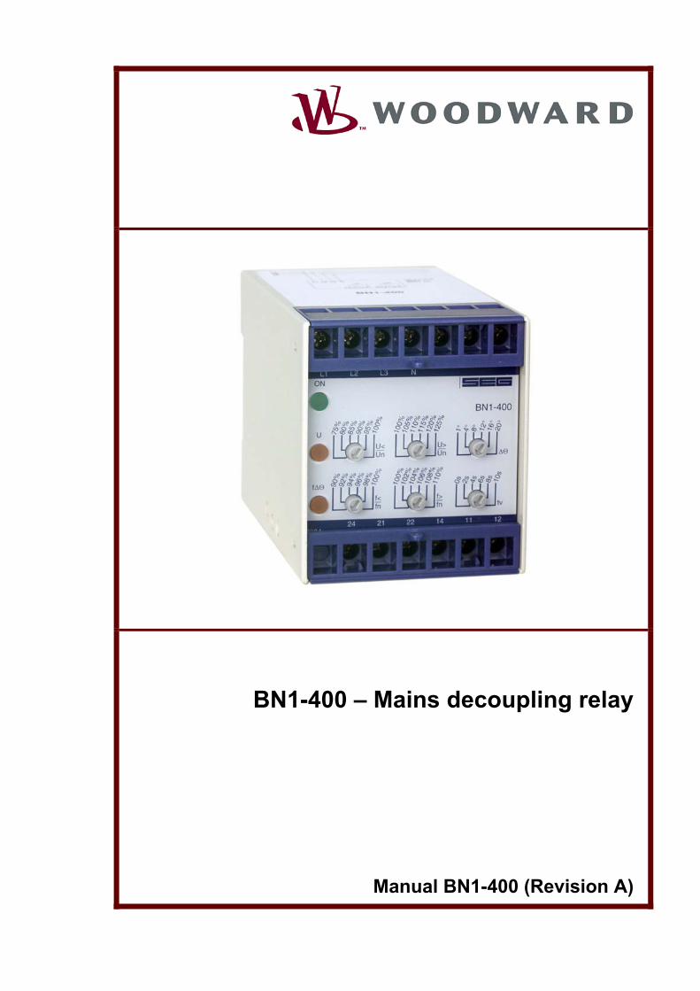
BN1-400 – Mains decoupling relay
Manual BN1-400 (Revision A)
Woodward Manual BN1-400 GB
Woodward Governor Company reserves the right to update any portion of this publication at any time. Information provided by Woodward Governor Company is believed to be correct and reliable. However, no responsibility is as-
sumed by Woodward Governor Company unless otherwise expressly undertaken.
© Woodward 1994-2008
2 DOK-TD-BN1-400E Rev.A

Contents 1. Applications and features ........................................................................... 4 2. Design ........................................................................................................... 5 3. Function ........................................................................................................ 6
3.1 Voltage supervision ............................................................................................................. 6 3.2 Frequency supervision ........................................................................................................ 6 3.3 The vector surge supervision .............................................................................................. 6
4. Operation and settings .............................................................................. 11 4.1 Setting of protection functions ........................................................................................... 12
5. Relay case and technical data .................................................................. 13 5.1 Relay case ......................................................................................................................... 13 5.2 Technical data ................................................................................................................... 14
DOK-TD-BN1-400E Rev.A 3
Woodward Manual BN1-400 GB
1. Applications and features Unit BN1-400 of the BASIC LINE is an universal mains decoupling device to monitor the phase-to-neutral volt-ages and contains the protective functions required of VDEW and most other utilities for the mains parallel operation of power stations: • over- and undervoltage protection • over- and underfrequency protection • fast decoupling of the generator in case of mains failure • Phase sequence supervision When compared to conventional devices an exceptional price/performance ratio is achieved by in-tegration of the three protective functions in one device. When compared to the conventional protection equipment all relays of the BASIC LINE reflect the superiority of digital protection techniques with the following features: • High measuring accuracy by digital data processing • Fault indication via LEDs • Very fine graded wide setting ranges • RMS measurement • Extremely short response time • Compact design by SMD-technology
4 DOK-TD-BN1-400E Rev.A
2. Design
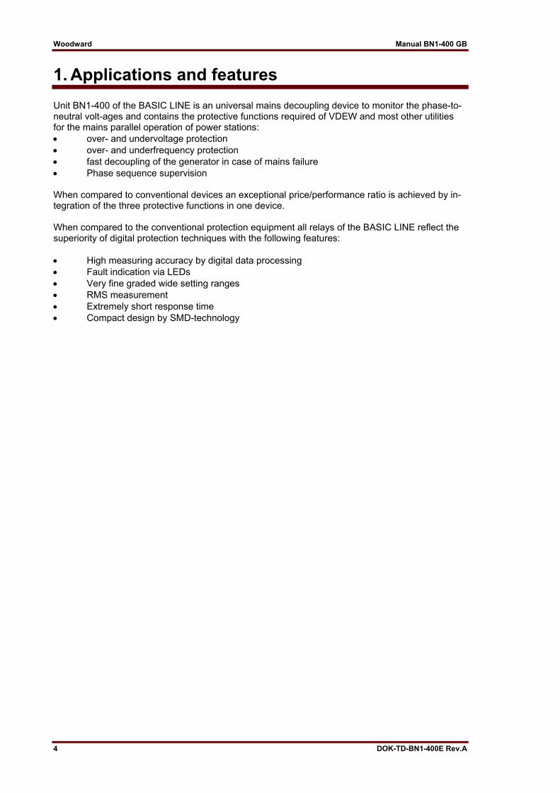
Figure 2.1: Connection four-wire system
Analog inputs The analog input signals of the voltages are connected to the protection device via terminals L1 - L3 and N. Supply Unit BN1-400 will be supplied directly from the measuring quantity itself (L1 and L3). The supply range is ±25% of UN = 400 V (phase-to-phase voltage). Contact positions
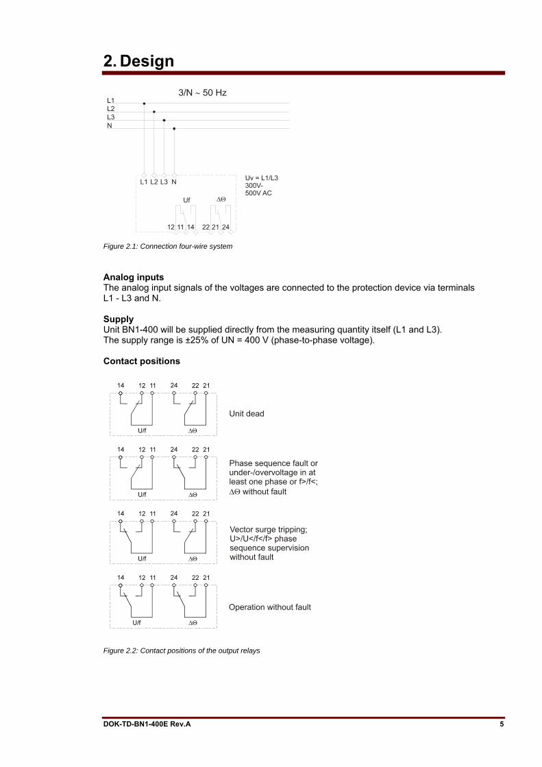
Figure 2.2: Contact positions of the output relays
DOK-TD-BN1-400E Rev.A 5
Woodward Manual BN1-400 GB
3. Function
3.1 Voltage supervision The BN1-400 has an independent under- and overvoltage supervision of the phase-to-neutral vol-tage. During 3-phase measuring the voltage is permanently compared with the set reference val-ues. For overvoltage supervision always the highest value is evaluated, for undervoltage supervision always the lowest value. Tripping at undervoltage is indicated by flashing LED U, whereas at overvoltage LED U is steady lit.
3.2 Frequency supervision For frequency supervision the cycle time is evaluated and so measuring is virtually independent on harmonic influences. To avoid tripping during normal operation due to voltages transients and phase transients - a fixed measuring repetition is used. Supervision of the frequency is 3-phase. Each of the phases is individually monitored. Pickup or tripping only after the set reference value in at least one phase is exceeded or not reached. Tripping at underfrequency f< is indicated by flashing of the LED fΔΘ. At overfrequency LED fΔΘ lights up permanently.
3.3 The vector surge supervision The vector surge supervision protects synchronous generators in mains parallel operation due to very fast de-coupling in case of mains failure. Very dangerous are mains auto reclosing for syn-chronous generators. The mains voltage returning after 300 ms can hit the generator in asynchron-ous mode. The same very fast de-coupling is also necessary in case of transients mains failures. Generally there are two different applications: a) Only mains parallel operation no single operation. In this application the vector surge supervision protects the generator by tripping the generator circuit breaker in case of mains failure. b) Mains parallel operation and single operation. For this application the vector surge supervision trips the mains circuit breaker. Here it is insured that the gen.-set is not blocked when it is required as the emergency set. A very fast decoupling in case of mains failures for synchronous generators is known as very diffi-cult. Volt-age supervision units cannot be used because the synchronous alternator as well as the consumer impedance support the decreasing voltage. The voltage reaches the threshold of voltage supervision unit because of this reason after a couple of 100 msec. and therefore a safe detection of auto re-closing in the mains is not possible with sin-gle-voltage supervision units. Also frequency relays cannot be used, because even a fully overloaded generator decreases the speed after 100 msec. Current protection relays detects the fault, by existing short circuit currents. Power sensing relays can also detects but cannot avoid the decreasing change of power to short circuit power. A problem is also the failure tripping of this kind of devices when to suddenly loading the generator. Without any mentioned limitation, the BN1-400 described detect mains failures with-in 70 ms, because it was specially designed for such kind of applications, where the kind of fault requi-res a very fast decoupling from the mains.
6 DOK-TD-BN1-400E Rev.A
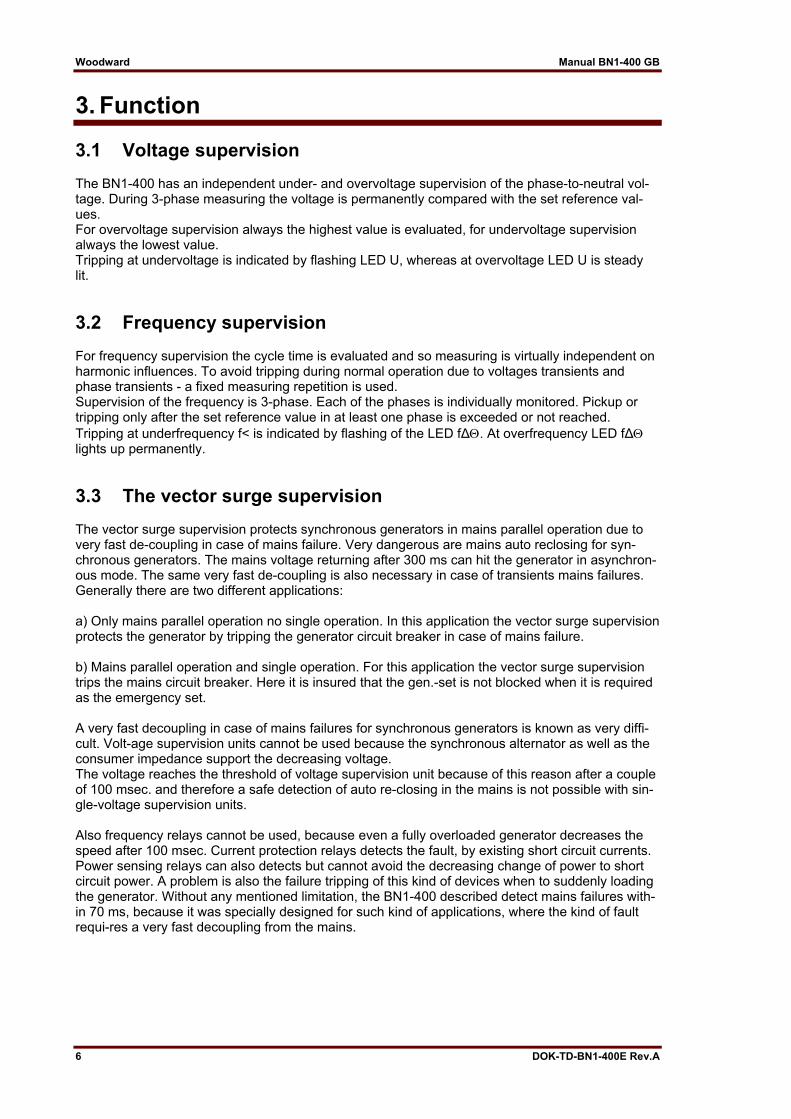
The total tripping time lies still under 170 ms even, when the circuit breaker time and the relay time is added. Requirement for a tripping of the generator mains monitor is a change of power of more than 15-20 % nominal power. Slow changes of the system frequency for example controlling of the governor does not trip the relay. Short circuits in the mains can also trip the relay, because a vector surge higher than the pre-set threshold can be detected. The value of the vector surge is de-pendent on the short circuit distance to the generator. This function offers the advantage for the utility that the mains short circuit capaci-ty and therefore the energy feeding the short circuit is limited. Measuring principle of vector surge When a synchronous alternator is loaded, the rotor displacement angle is build between the ter-minal volt-age (mains voltage U1) and the synchronous electro-motive force (Up). Therefore a vol-tage is difference ΔU is built between Up and U1 (Figure 3.1).
Figure 3.1: Equivalent circuit at synchronous generator in parallel with the mains
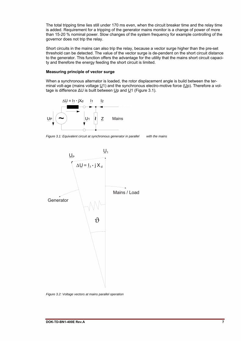
Figure 3.2: Voltage vectors at mains parallel operation
DOK-TD-BN1-400E Rev.A 7
Woodward Manual BN1-400 GB
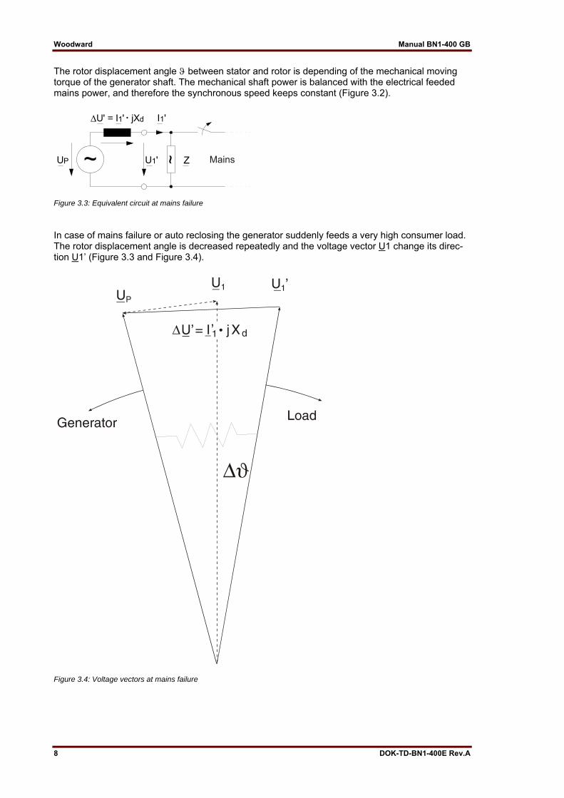
The rotor displacement angle ϑ between stator and rotor is depending of the mechanical moving torque of the generator shaft. The mechanical shaft power is balanced with the electrical feeded mains power, and therefore the synchronous speed keeps constant (Figure 3.2).
Figure 3.3: Equivalent circuit at mains failure
In case of mains failure or auto reclosing the generator suddenly feeds a very high consumer load. The rotor displacement angle is decreased repeatedly and the voltage vector U1 change its direc-tion U1’ (Figure 3.3 and Figure 3.4).
Figure 3.4: Voltage vectors at mains failure
8 DOK-TD-BN1-400E Rev.A
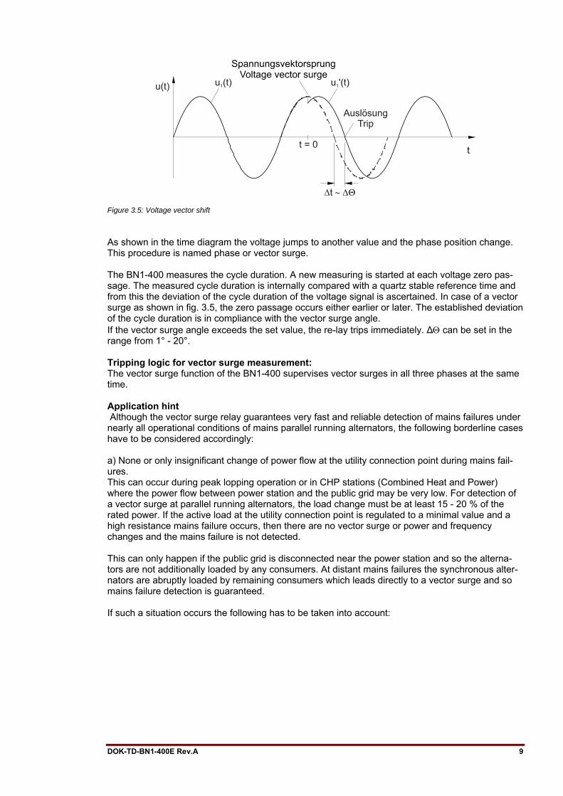
Figure 3.5: Voltage vector shift
As shown in the time diagram the voltage jumps to another value and the phase position change. This procedure is named phase or vector surge. The BN1-400 measures the cycle duration. A new measuring is started at each voltage zero pas-sage. The measured cycle duration is internally compared with a quartz stable reference time and from this the deviation of the cycle duration of the voltage signal is ascertained. In case of a vector surge as shown in fig. 3.5, the zero passage occurs either earlier or later. The established deviation of the cycle duration is in compliance with the vector surge angle. If the vector surge angle exceeds the set value, the re-lay trips immediately. ΔΘ can be set in the range from 1° - 20°. Tripping logic for vector surge measurement: The vector surge function of the BN1-400 supervises vector surges in all three phases at the same time. Application hint Although the vector surge relay guarantees very fast and reliable detection of mains failures under nearly all operational conditions of mains parallel running alternators, the following borderline cases have to be considered accordingly: a) None or only insignificant change of power flow at the utility connection point during mains fail-ures. This can occur during peak lopping operation or in CHP stations (Combined Heat and Power) where the power flow between power station and the public grid may be very low. For detection of a vector surge at parallel running alternators, the load change must be at least 15 - 20 % of the rated power. If the active load at the utility connection point is regulated to a minimal value and a high resistance mains failure occurs, then there are no vector surge or power and frequency changes and the mains failure is not detected. This can only happen if the public grid is disconnected near the power station and so the alterna-tors are not additionally loaded by any consumers. At distant mains failures the synchronous alter-nators are abruptly loaded by remaining consumers which leads directly to a vector surge and so mains failure detection is guaranteed. If such a situation occurs the following has to be taken into account:
DOK-TD-BN1-400E Rev.A 9
Woodward Manual BN1-400 GB
In case of an undetected mains failure, i.e. with the mains coupling C.B. in operation, the vector surge relay reacts upon the first load change causing a vector surge and isolates the mains C.B. For detecting high resistance mains failures a zero sequence relay with an adjustable time delay can be used. A time delay is needed to allow regulating actions where the current may reach "zero" at the utility connection point. At high resistance mains failures, the mains coupling C.B. is tripped by the zero sequence relay after the time delay. To prevent asynchronous switching on, an automatic restart by the public grid should be not possi-ble during this time delay. As a further measure the load regulation at the utility connection point should be such that an ac-tive energy of 5 % of the alternator rated power is always flowing. b) Short circuit type loading of the alternators at distant mains failures At any distant mains failure, the remaining consumers cause sudden short circuit type loading of the power station alternators. The vector surge relay detects the mains failure in about 70 ms and switches off the mains coupling C.B. The total switch off time is about 150 - 170 ms. If the alterna-tors are provided with an extremely fast short circuit protection e.g. able to detect di/dt, the alterna-tors might be switched off unselectively by the alternator C.B., which is not desirable because the power supply for the station is endangered and later on synchronized changeover to the mains is only possible after manual reset of the overcurrent protection. To avoid such a situation, the alternator C.B.s must have a delayed short circuit protection. The de-lay time must be long enough so that mains disconnection by the vector surge relay is guaranteed.
10 DOK-TD-BN1-400E Rev.A
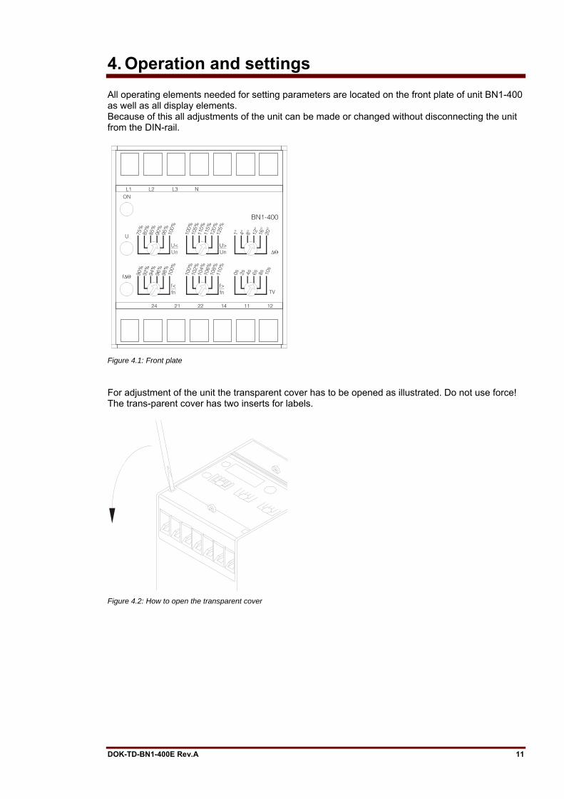
4. Operation and settings All operating elements needed for setting parameters are located on the front plate of unit BN1-400 as well as all display elements. Because of this all adjustments of the unit can be made or changed without disconnecting the unit from the DIN-rail.
Figure 4.1: Front plate
For adjustment of the unit the transparent cover has to be opened as illustrated. Do not use force! The trans-parent cover has two inserts for labels.
Figure 4.2: How to open the transparent cover
DOK-TD-BN1-400E Rev.A 11
Woodward Manual BN1-400 GB
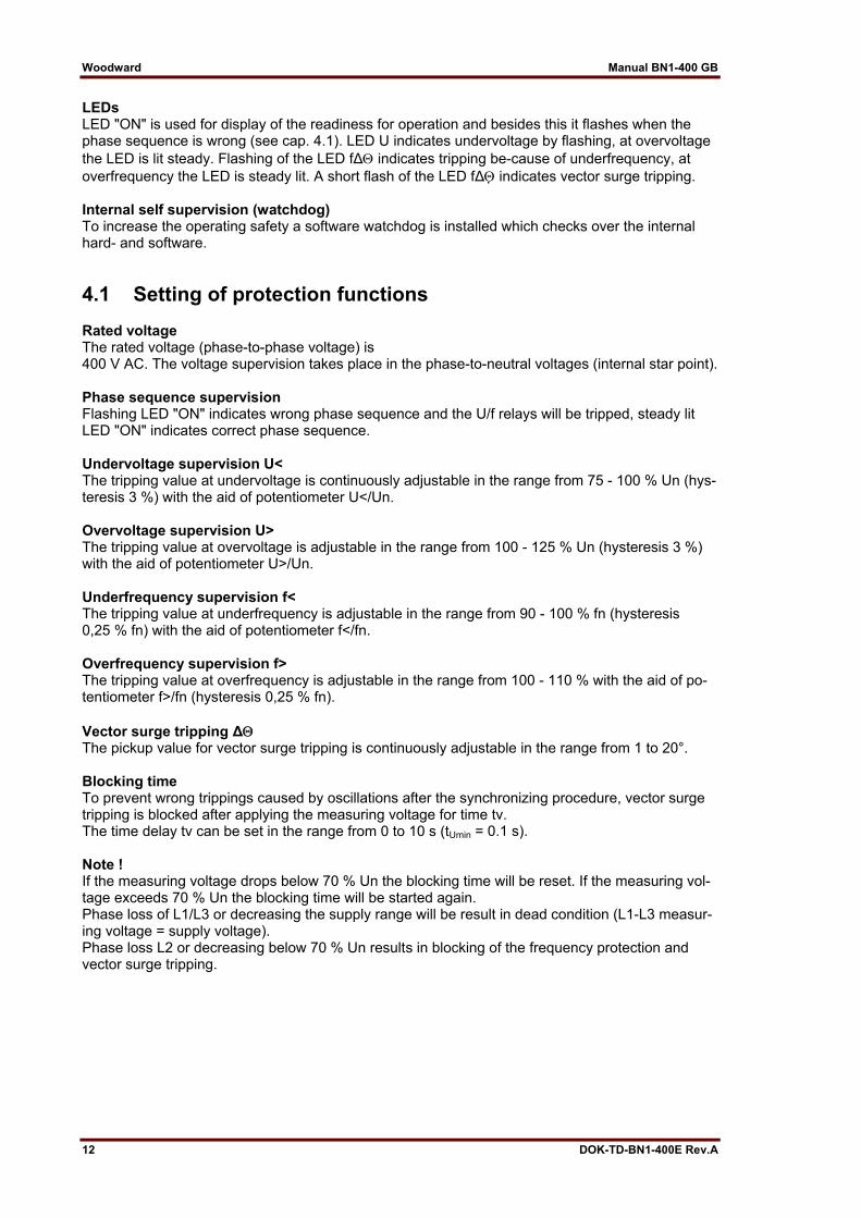
LEDs LED "ON" is used for display of the readiness for operation and besides this it flashes when the phase sequence is wrong (see cap. 4.1). LED U indicates undervoltage by flashing, at overvoltage the LED is lit steady. Flashing of the LED fΔΘ indicates tripping be-cause of underfrequency, at overfrequency the LED is steady lit. A short flash of the LED fΔΘ indicates vector surge tripping. Internal self supervision (watchdog) To increase the operating safety a software watchdog is installed which checks over the internal hard- and software.
4.1 Setting of protection functions Rated voltage The rated voltage (phase-to-phase voltage) is 400 V AC. The voltage supervision takes place in the phase-to-neutral voltages (internal star point). Phase sequence supervision Flashing LED "ON" indicates wrong phase sequence and the U/f relays will be tripped, steady lit LED "ON" indicates correct phase sequence. Undervoltage supervision U< The tripping value at undervoltage is continuously adjustable in the range from 75 - 100 % Un (hys-teresis 3 %) with the aid of potentiometer U</Un. Overvoltage supervision U> The tripping value at overvoltage is adjustable in the range from 100 - 125 % Un (hysteresis 3 %) with the aid of potentiometer U>/Un. Underfrequency supervision f< The tripping value at underfrequency is adjustable in the range from 90 - 100 % fn (hysteresis 0,25 % fn) with the aid of potentiometer f</fn. Overfrequency supervision f> The tripping value at overfrequency is adjustable in the range from 100 - 110 % with the aid of po-tentiometer f>/fn (hysteresis 0,25 % fn). Vector surge tripping ΔΘ The pickup value for vector surge tripping is continuously adjustable in the range from 1 to 20°. Blocking time To prevent wrong trippings caused by oscillations after the synchronizing procedure, vector surge tripping is blocked after applying the measuring voltage for time tv. The time delay tv can be set in the range from 0 to 10 s (tUmin = 0.1 s). Note ! If the measuring voltage drops below 70 % Un the blocking time will be reset. If the measuring vol-tage exceeds 70 % Un the blocking time will be started again. Phase loss of L1/L3 or decreasing the supply range will be result in dead condition (L1-L3 measur-ing voltage = supply voltage). Phase loss L2 or decreasing below 70 % Un results in blocking of the frequency protection and vector surge tripping.
12 DOK-TD-BN1-400E Rev.A
5. Relay case and technical data
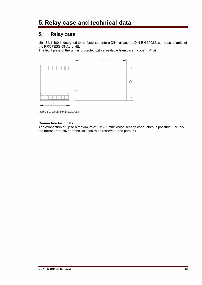
5.1 Relay case Unit BN1-400 is designed to be fastened onto a DIN-rail acc. to DIN EN 50022, same as all units of the PROFESSIONAL LINE. The front plate of the unit is protected with a sealable transparent cover (IP40).
Figure 5.1: Dimensional drawings
Connection terminals The connection of up to a maximum of 2 x 2.5 mm2 cross-section conductors is possible. For this the transparent cover of the unit has to be removed (see para. 4).
DOK-TD-BN1-400E Rev.A 13
Woodward Manual BN1-400 GB
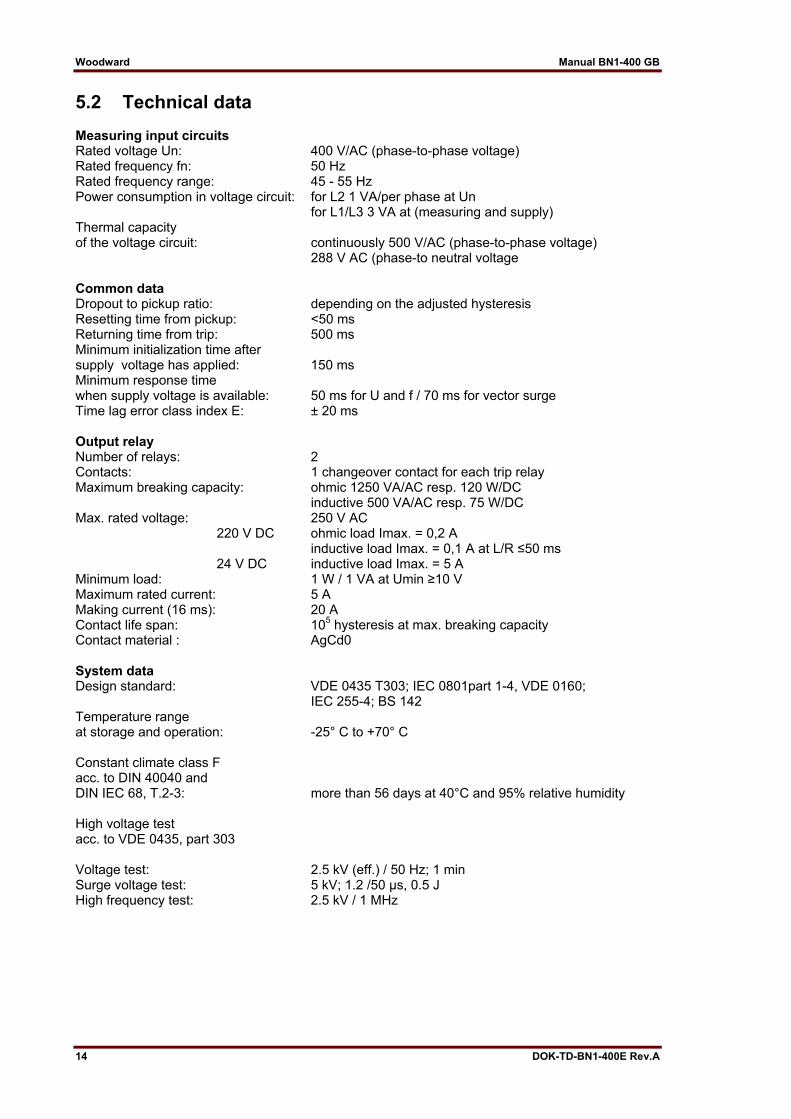
5.2 Technical data Measuring input circuits Rated voltage Un: 400 V/AC (phase-to-phase voltage) Rated frequency fn: 50 Hz Rated frequency range: 45 - 55 Hz Power consumption in voltage circuit: for L2 1 VA/per phase at Un for L1/L3 3 VA at (measuring and supply) Thermal capacity of the voltage circuit: continuously 500 V/AC (phase-to-phase voltage) 288 V AC (phase-to neutral voltage Common data Dropout to pickup ratio: depending on the adjusted hysteresis Resetting time from pickup: <50 ms Returning time from trip: 500 ms Minimum initialization time after supply voltage has applied: 150 ms Minimum response time when supply voltage is available: 50 ms for U and f / 70 ms for vector surge Time lag error class index E: ± 20 ms Output relay Number of relays: 2 Contacts: 1 changeover contact for each trip relay Maximum breaking capacity: ohmic 1250 VA/AC resp. 120 W/DC inductive 500 VA/AC resp. 75 W/DC Max. rated voltage: 250 V AC 220 V DC ohmic load Imax. = 0,2 A inductive load Imax. = 0,1 A at L/R ≤50 ms 24 V DC inductive load Imax. = 5 A Minimum load: 1 W / 1 VA at Umin ≥10 V Maximum rated current: 5 A Making current (16 ms): 20 A Contact life span: 105 hysteresis at max. breaking capacity Contact material : AgCd0 System data Design standard: VDE 0435 T303; IEC 0801part 1-4, VDE 0160; IEC 255-4; BS 142 Temperature range at storage and operation: -25° C to +70° C Constant climate class F acc. to DIN 40040 and DIN IEC 68, T.2-3: more than 56 days at 40°C and 95% relative humidity High voltage test acc. to VDE 0435, part 303 Voltage test: 2.5 kV (eff.) / 50 Hz; 1 min Surge voltage test: 5 kV; 1.2 /50 µs, 0.5 J High frequency test: 2.5 kV / 1 MHz
14 DOK-TD-BN1-400E Rev.A
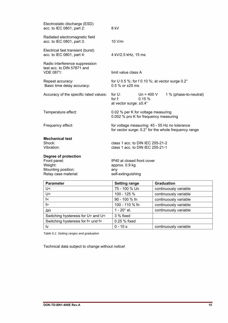
Electrostatic discharge (ESD) acc. to IEC 0801, part 2: 8 kV Radiated electromagnetic field acc. to IEC 0801, part 3: 10 V/m Electrical fast transient (burst) acc. to IEC 0801, part 4: 4 kV/2.5 kHz, 15 ms Radio interference suppression test acc. to DIN 57871 and VDE 0871: limit value class A Repeat accuracy: for U 0.5 %; for f 0.10 %; at vector surge 0.2° Basic time delay accuracy: 0.5 % or ±25 ms Accuracy of the specific rated values: for U: Un = 400 V 1 % (phase-to-neutral) for f: 0.15 % at vector surge: ±0.4° Temperature effect: 0.02 % per K for voltage measuring 0.002 % pro K for frequency measuring Frequency effect: for voltage measuring: 45 - 55 Hz no tolerance for vector surge: 0.2° for the whole frequency range Mechanical test Shock: class 1 acc. to DIN IEC 255-21-2 Vibration: class 1 acc. to DIN IEC 255-21-1 Degree of protection Front panel: IP40 at closed front cover Weight: approx. 0.9 kg Mounting position: any Relay case material: self-extinguishing Parameter Setting range Graduation U< 75 - 100 % Un continuously variable U> 100 - 125 % continuously variable f< 90 - 100 % fn continuously variable f> 100 - 110 % fn continuously variable ΔΘ 1 - 20° el. continuously variable Switching hysteresis for U> and U< 3 % fixed Switching hysteresis for f> und f< 0.25 % fixed tv 0 - 10 s continuously variable
Table 5.1: Setting ranges and graduation
Technical data subject to change without notice!
DOK-TD-BN1-400E Rev.A 15
Woodward Manual BN1-400 GB
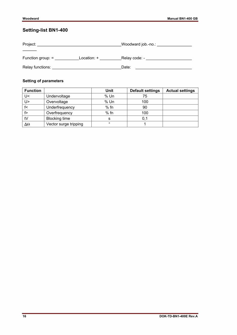
Setting-list BN1-400 Project: Woodward job.-no.: Function group: = Location: + Relay code: - Relay functions: Date: Setting of parameters Function Unit Default settings Actual settings U< Undervoltage % Un 75 U> Overvoltage % Un 100 f< Underfrequency % fn 90 f> Overfrequency % fn 100 tV Blocking time s 0,1 ΔΘ Vector surge tripping ° 1
16 DOK-TD-BN1-400E Rev.A

DOK-TD-BN1-400E Rev.A 17

Woodward Manual BN1-400 GB
Woodward Kempen GmbH Krefelder Weg 47 ⋅ D – 47906 Kempen (Germany)
Postfach 10 07 55 (P.O.Box) ⋅ D – 47884 Kempen (Germany) Phone: +49 (0) 21 52 145 1
Internet
www.woodward.com
Sales Phone: +49 (0) 21 52 145 216 or 342 ⋅ Telefax: +49 (0) 21 52 145 354
e-mail: [email protected]
Service Phone: +49 (0) 21 52 145 614 ⋅ Telefax: +49 (0) 21 52 145 455
e-mail: [email protected]
18 DOK-TD-BN1-400E Rev.A