Embed Size (px)
Citation preview

10-I
Cylin
de
rs
Pneumatic cylinders Ø 32 ÷ 200 mm according to ISO 6431 and VDMA 24562with adjustable cushioning
UNIVER pneumatic cylinders which comply with ISO 6431 and VDMA 24562 standards, take advantage of the
improvements arising from the research of the last years; infact, they can fully satisfy the most demanding users.
The operation with non-lubricated air is worth mentioning, since it allows their use in many industrial sectors while
protecting the environment. The strong construction and the selected components contribute to giving them
excellent operating features and a very long life.
Working pressure: 1,5 ÷ 10 barAmbient temperature: -20 ÷ 80°C.Fluid: filtered air, with or without lubrication.Barrel: internal/external anodised aluminium and
piston rod in chromium-plated steel standard.Bores: series KD 32 ÷ 125 aluminium barrel with profiles
for flush-mounted sensors, magnetic versionstandard.series K 32÷ 200 aluminium barrel;Ø160 ÷ 200 mm with round aluminium barreland steel tie-rods, magnetic version upon request.
6431VDMA
24562
OPTION
Flush-mounted magnetic sensors DF---- series for KD series.Wire protection strap magnetic sensorfor KD series part no. DHF-002100.Magnetic sensor DH---- Series for K series.(Section Accessories page 2)Accessories as from page 15.
Upon request- Magnetic rings in plastoferrite
- Locking units Ø 32 ÷ 125 mm to be coupled only with
chromium-plated steel rod series KD2-…
(section High-Tech page 3)
- Slide units Ø 32 ÷ 100 mm (section High-Tech page 36)
- Cylinders with rigid bushing, in tandem, multiple position
and opposed version (page 13).
Construction detailsClean line barrel produced from extruded aluminium alloy with
ribbed "anti-twist" design. Internal and external surfaces
anodised to 15 micron.
Die-cast end-caps in aluminium alloy mounted on the barrel
holes with self-tapping steel screws.
Pneumatic adjustable cushions provide efficient piston
deceleration.
Synthetic rubber shock absorbers avoid mechanical stress and
reduce machinery noise (lower than 50 dB).
Die-cast aluminum alloy piston and guide shoe in acetalic resin
with a permanent plastoferrite magnetic ring (upon request for
the magnetic version).
The piston and cushion seals are made of a wear-resistant nitrile
rubber compound suitable for applications with or without
lubrication. The double lip seal design automatically self-
compensates against wear.
Hardened stainless steel rod (K-KD...100 series) or chromium-
plated (K-KD...200 series) with 2 micron Ra.; supplied with nut.
UNIVER original self-lubricating and self-aligning piston rod bush.
For special applications, rigid bushings are supplied upon
request.
Cylinders Ø 125-160-200 with rigid piston rod bushing standard
supplied.
TECHNICAL CHARACTERISTICS
F = For use with locking unit with "reduced dimensions"
G = For use with locking unit with ISO dimensions
M= Magnetic version
Series K----
Series KD----
Codification key
Stainless steel rod
Stainless steel through rod
Stainless steel retracted rod, max. stroke 50 mm
Stainless steel extended rod, max. stroke 50 mm
Chromium-plated rod
Chromium-plated through rod
Chromium-plated retracted rod, max stroke 50 mm
Chromium-plated extended rod, max stroke 50 mm
1
1
06 S.A.07 S.A.00 D.A.10 D.A.06 S.A.07 S.A.
00
10
1
12
2
2
2
D.A.D.A.
Standard strokes in mm: 0025 - 0050 - 0075 - 0080 - 0100
0125 - 0150 - 0160 - 0175 - 0200 - 0250 - 0300 - 0320 - 0350
0400 - 0450 - 0500 - 0600 - 0700 - 0800 - 0900 - 1000
STROKE
BORE
Ø 032 - 040 - 050 - 063 - 080 - 0100 - 0125 - 0160 - 0200
TYPE
SERIES
Stroke (in mm)
Bore (in mm)
Type
Series
Option
KD = ø 32÷125 mm magnetic version standard.
K = ø 32÷200 mm magnetic version upon request.
KD 200 032 0050 G M
11-I
Cylin
de
rs
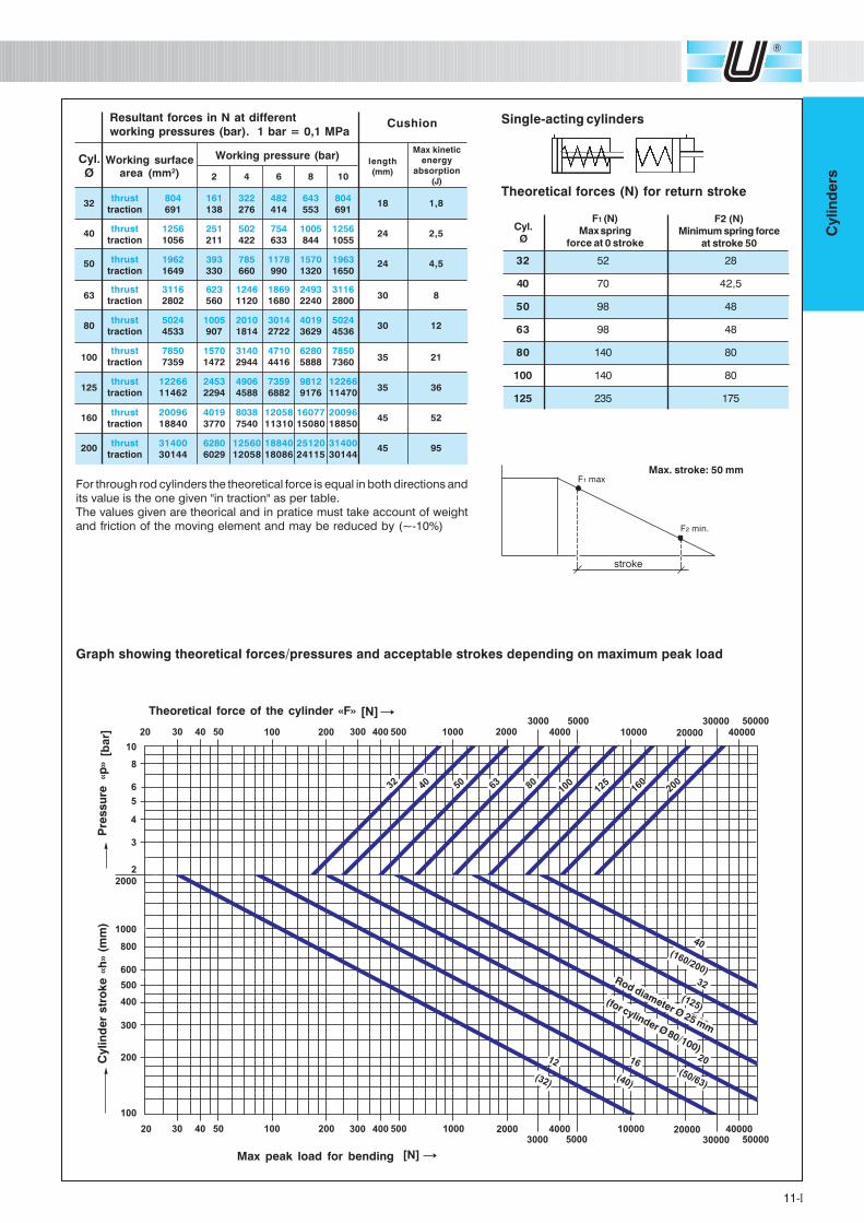
Resultant forces in N at differentworking pressures (bar). 1 bar = 0,1 MPa
Cyl.Ø
Working surfacearea (mm2) 2 4 6 8 10
thrust 804 161 322 482 643 804
traction 691 138 276 414 553 691
thrust 1256 251 502 754 1005 1256
traction 1056 211 422 633 844 1055
thrust 1962 393 785 1178 1570 1963
traction 1649 330 660 990 1320 1650
thrust 3116 623 1246 1869 2493 3116
traction 2802 560 1120 1680 2240 2800
thrust 5024 1005 2010 3014 4019 5024
traction 4533 907 1814 2722 3629 4536
thrust 7850 1570 3140 4710 6280 7850
traction 7359 1472 2944 4416 5888 7360
thrust 12266 2453 4906 7359 9812 12266
traction 11462 2294 4588 6882 9176 11470
thrust 20096 4019 8038 12058 16077 20096
traction 18840 3770 7540 11310 15080 18850
thrust 31400 6280 12560 18840 25120 31400
traction 30144 6029 12058 18086 24115 30144
32
40
50
63
80
100
125
160
200
18
24
24
30
30
35
35
45
45
1,8
2,5
4,5
8
12
21
36
52
95
Max kinetic
energy
absorption
(J)
Working pressure (bar)
Cushion
length
(mm)
Graph showing theoretical forces/pressures and acceptable strokes depending on maximum peak load
F1 (N)Max spring
force at 0 stroke
F2 (N)Minimum spring force
at stroke 50
Single-acting cylinders
Theoretical forces (N) for return stroke
32 52 28
40 70 42,5
50 98 48
63 98 48
80 140 80
100 140 80
125 235 175
Cyl.Ø
Max. stroke: 50 mm
stroke
F1 max
F2 min.
Theoretical force of the cylinder «F»
Max peak load for bending
Cylin
der
str
oke
«h
» (m
m)
Pre
ssu
re «p
»
Rod diameter Ø 25 mm
(for cylinder Ø 80/100)
For through rod cylinders the theoretical force is equal in both directions and
its value is the one given "in traction" as per table.
The values given are theorical and in pratice must take account of weight
and friction of the moving element and may be reduced by (~-10%)
12-I
Cylin
de
rs
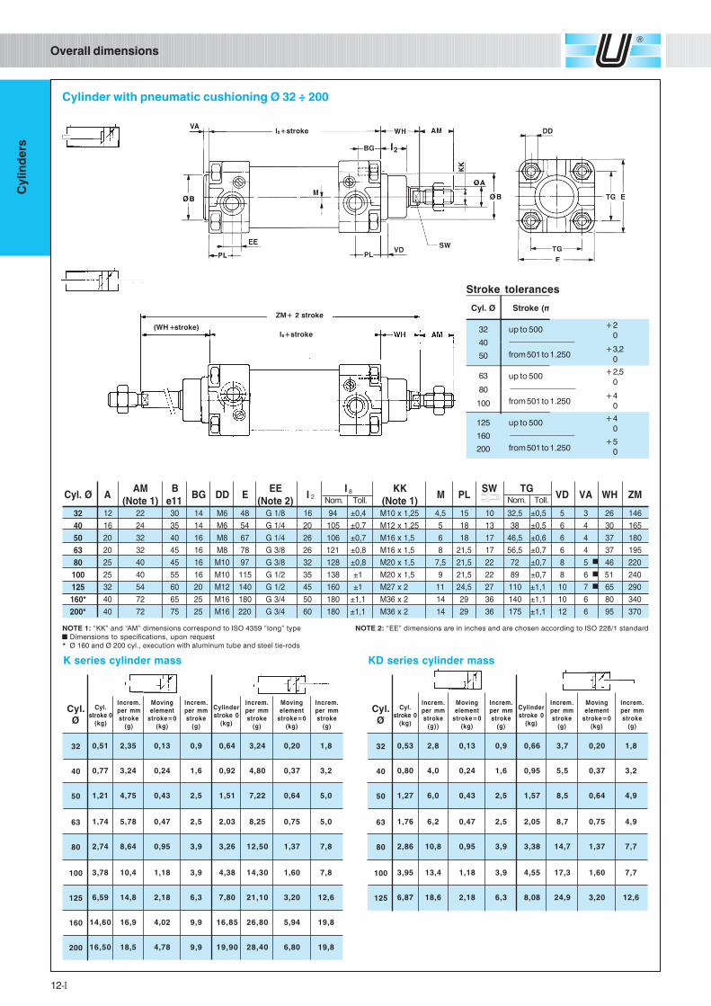
2Nom. Toll. Nom. Toll.
8Ø.lyC AMA
)1etoN(B11e
GB DD EEE
)2etoN(I
I KK)1etoN(
M LPWS GT
DV AV HW MZ
23 21 22 03 41 6M 84 8/1G 61 49 4,0± 52,1x01M 5,4 51 01 5,23 5,0± 5 3 62 641
04 61 42 53 41 6M 45 4/1G 02 501 7,0± 52,1x21M 5 81 31 83 5,0± 6 4 03 561
05 02 23 04 61 8M 76 4/1G 62 601 7,0± 5,1x61M 6 81 71 5,64 6,0± 6 4 73 081
36 02 23 54 61 8M 87 8/3G 62 121 8,0± 5,1x61M 8 5,12 71 5,65 7,0± 6 4 73 591
08 52 04 54 61 01M 79 8/3G 23 821 8,0± 5,1x02M 5,7 5,12 22 27 7,0± 8 5 64 022
001 52 04 55 61 01M 511 2/1G 53 831 1± 5,1x02M 9 5,12 22 98 7,0± 8 6 15 042
521 23 45 06 02 21M 041 2/1G 54 061 1± 2x72M 11 5,42 72 011 1,1± 01 7 56 092
*061 04 27 56 52 61M 081 4/3G 05 081 1,1± 2x63M 41 92 63 041 1,1± 01 6 08 043
*002 04 27 57 52 61M 022 4/3G 06 081 1,1± 2x63M 41 92 63 571 1,1± 21 6 59 073
Cylinder with pneumatic cushioning Ø 32 ÷ 200
Overall dimensions
l8+stroke
l8+stroke
ZM+ 2 stroke
(WH + stroke)
Cyl. Ø Stroke (m
+2
0
+3,2
0
+2,5
0
+4
0
+4
0
+5
0
Stroke tolerances
32
40
50
63
80
100
125
160
200
up to 500
from 501 to 1.250
up to 500
from 501 to 1.250
up to 500
from 501 to 1.250
NOTE 1: “KK” and “AM” dimensions correspond to ISO 4359 “long” type NOTE 2: “EE” dimensions are in inches and are chosen according to ISO 228/1 standard
Dimensions to specifications, upon request
* Ø 160 and Ø 200 cyl., execution with aluminum tube and steel tie-rods
32
40
50
63
80
100
125
160
200
0,51
0,77
1,21
1,74
2,74
3,78
6,59
14,60
16,50
2,35
3,24
4,75
5,78
8,64
10,4
14,8
16,9
18,5
0,13
0,24
0,43
0,47
0,95
1,18
2,18
4,02
4,78
0,9
1,6
2,5
2,5
3,9
3,9
6,3
9,9
9,9
0,64
0,92
1,51
2,03
3,26
4,38
7,80
16,85
19,90
3,24
4,80
7,22
8,25
12,50
14,30
21,10
26,80
28,40
0,20
0,37
0,64
0,75
1,37
1,60
3,20
5,94
6,80
1,8
3,2
5,0
5,0
7,8
7,8
12,6
19,8
19,8
Cyl.
stroke 0
(kg)
Increm.
per mm
stroke
(g)
Moving
element
stroke=0
(kg)
Increm.
per mm
stroke
(g)
Cylinder
stroke 0
(kg)
Increm.
per mm
stroke
(g)
Moving
element
stroke=0
(kg)
Increm.
per mm
stroke
(g)
Cyl.Ø
32
40
50
63
80
100
125
0,53
0,80
1,27
1,76
2,86
3,95
6,87
2,8
4,0
6,0
6,2
10,8
13,4
18,6
0,13
0,24
0,43
0,47
0,95
1,18
2,18
0,9
1,6
2,5
2,5
3,9
3,9
6,3
0,66
0,95
1,57
2,05
3,38
4,55
8,08
3,7
5,5
8,5
8,7
14,7
17,3
24,9
0,20
0,37
0,64
0,75
1,37
1,60
3,20
1,8
3,2
4,9
4,9
7,7
7,7
12,6
Cyl.
stroke 0
(kg)
Increm.
per mm
stroke
(g))
Moving
element
stroke=0
(kg)
Increm.
per mm
stroke
(g)
Cylinder
stroke 0
(kg)
Increm.
per mm
stroke
(g)
Moving
element
stroke=0
(kg)
Increm.
per mm
stroke
(g)
Cyl.Ø
K series cylinder mass KD series cylinder mass
13-I
Cylin
de
rs
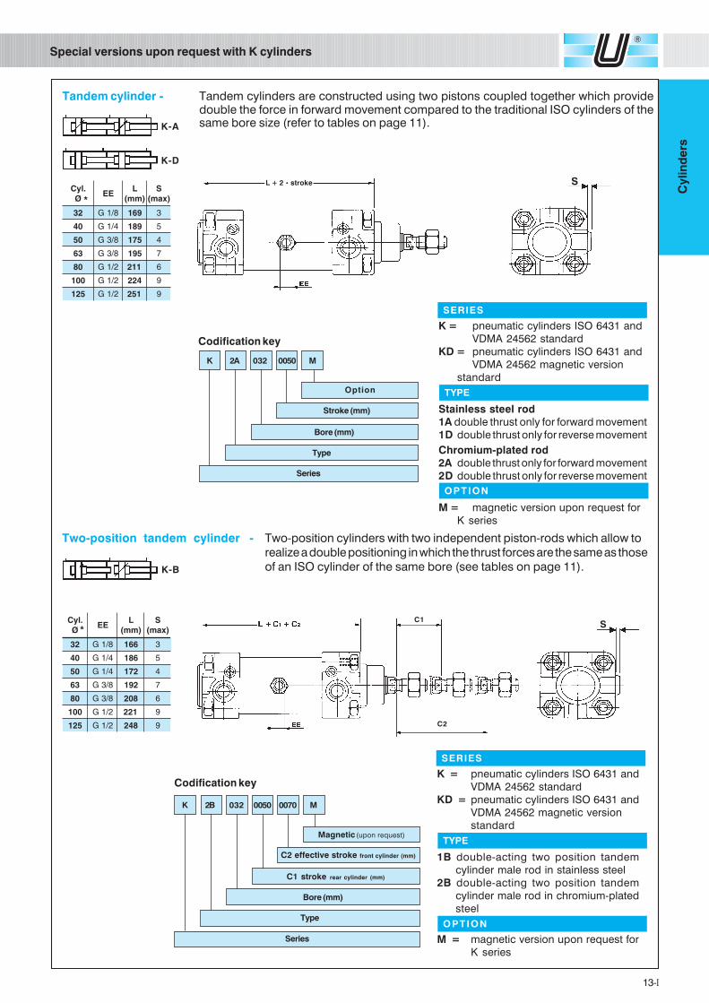
Special versions upon request with K cylinders
Codification key
K 2A 032 0050 M
Stroke (mm)
Bore (mm)
Type
Series
Option
SERIES
K = pneumatic cylinders ISO 6431 and
VDMA 24562 standard
KD = pneumatic cylinders ISO 6431 and
VDMA 24562 magnetic version
standard
Stainless steel rod
1A double thrust only for forward movement
1D double thrust only for reverse movement
Chromium-plated rod
2A double thrust only for forward movement
2D double thrust only for reverse movement
M = magnetic version upon request for
K series
Codification key
C2 effective stroke front cylinder (mm)
C1 stroke rear cylinder (mm)
Bore (mm)
Type
Magnetic (upon request)
Series
K 2B 032 0050 0070 M
L + 2 • stroke S
*
*S
C1
C2
K-A
K-D
K-B
Tandem cylinder - Tandem cylinders are constructed using two pistons coupled together which providedouble the force in forward movement compared to the traditional ISO cylinders of thesame bore size (refer to tables on page 11).
Two-position tandem cylinder - Two-position cylinders with two independent piston-rods which allow to
realize a double positioning in which the thrust forces are the same as those
of an ISO cylinder of the same bore (see tables on page 11).
.lyCØ
EEL
)mm(S
)xam(
23 8/1G 661 3
04 4/1G 681 5
05 4/1G 271 4
36 8/3G 291 7
08 8/3G 802 6
001 2/1G 122 9
521 2/1G 842 9
.lyCØ
EEL
)mm(S
)xam(
23 8/1G 961 3
04 4/1G 981 5
05 8/3G 571 4
36 8/3G 591 7
08 2/1G 112 6
001 2/1G 422 9
521 2/1G 152 9
TYPE
OPTION
SERIES
K = pneumatic cylinders ISO 6431 and
VDMA 24562 standard
KD = pneumatic cylinders ISO 6431 and
VDMA 24562 magnetic version
standard
1B double-acting two position tandem
cylinder male rod in stainless steel
2B double-acting two position tandem
cylinder male rod in chromium-plated
steel
M = magnetic version upon request for
K series
TYPE
OPTION
14-I
Cylin
de
rs
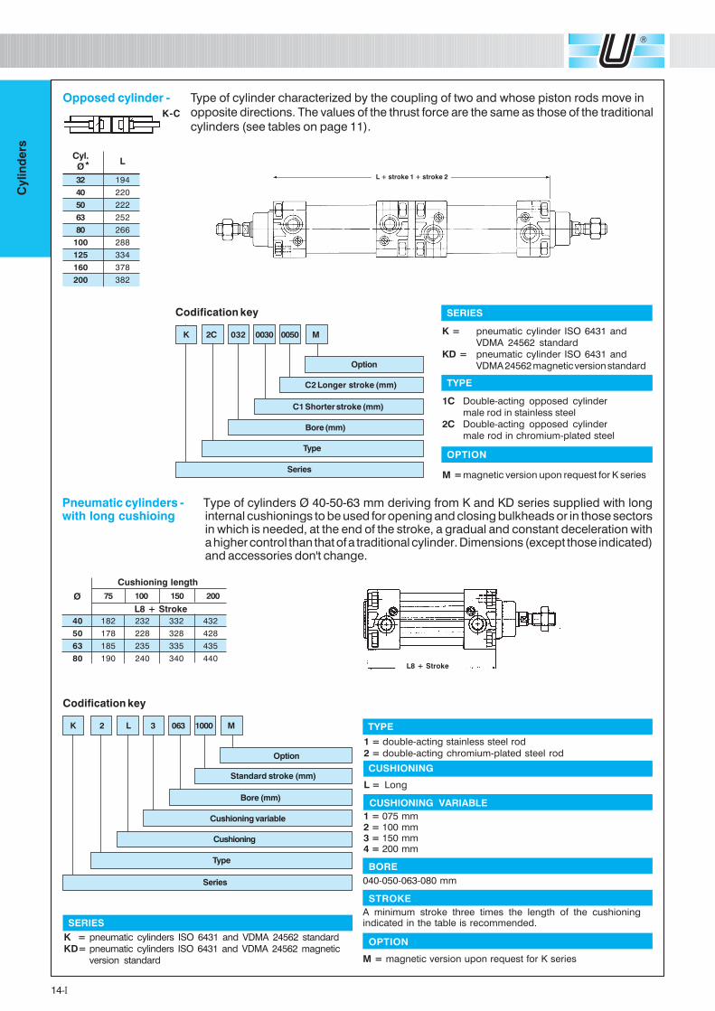
Type of cylinders Ø 40-50-63 mm deriving from K and KD series supplied with longinternal cushionings to be used for opening and closing bulkheads or in those sectorsin which is needed, at the end of the stroke, a gradual and constant deceleration witha higher control than that of a traditional cylinder. Dimensions (except those indicated)and accessories don't change.
TYPE
1 = double-acting stainless steel rod
2 = double-acting chromium-plated steel rod
1 = 075 mm2 = 100 mm3 = 150 mm4 = 200 mm
CUSHIONING VARIABLE
CUSHIONING
L = Long
SERIES
K = pneumatic cylinders ISO 6431 and VDMA 24562 standard
KD= pneumatic cylinders ISO 6431 and VDMA 24562 magnetic
version standard
Codification key
Standard stroke (mm)
Bore (mm)
Cushioning variable
Cushioning
Option
Type
Series
K 2 L 3 063 1000 M
040-050-063-080 mm
BORE
A minimum stroke three times the length of the cushioningindicated in the table is recommended.
STROKE
M = magnetic version upon request for K series
OPTION
L8 + Stroke
40 182 232 332 432
50 178 228 328 428
63 185 235 335 435
80 190 240 340 440
Cushioning length
L8 + Stroke
75 100 150 200Ø
Opposed cylinder - Type of cylinder characterized by the coupling of two and whose piston rods move in
opposite directions. The values of the thrust force are the same as those of the traditional
cylinders (see tables on page 11).
L + stroke 1 + stroke 2
K-C
TYPE
1C Double-acting opposed cylinder
male rod in stainless steel
2C Double-acting opposed cylinder
male rod in chromium-plated steel
Codification key
C2 Longer stroke (mm)
C1 Shorter stroke (mm)
Bore (mm)
Type
Option
Series
K 2C 032 0030 0050 M
*Cyl.
LØ
32 194
40 220
50 222
63 252
80 266
100 288
125 334
160 378
200 382
OPTION
M =magnetic version upon request for K series
SERIES
K = pneumatic cylinder ISO 6431 and
VDMA 24562 standard
KD = pneumatic cylinder ISO 6431 and
VDMA 24562 magnetic version standard
Pneumatic cylinders -with long cushioing
15-I
Cylin
de
rs
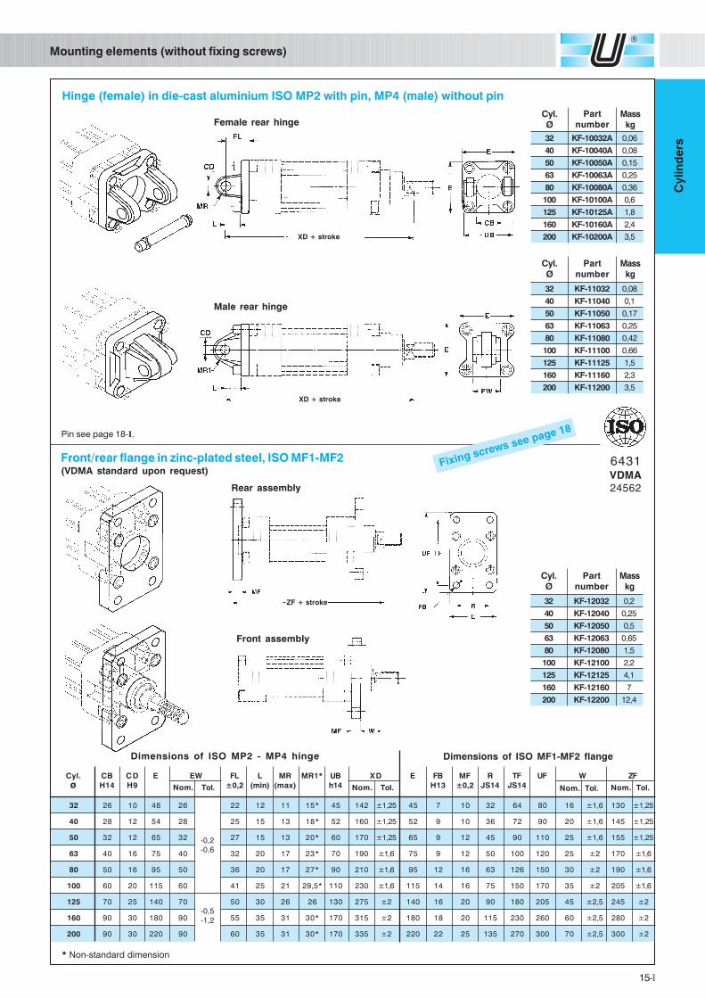
Dimensions of ISO MF1-MF2 flange
Mounting elements (without fixing screws)
Hinge (female) in die-cast aluminium ISO MP2 with pin, MP4 (male) without pin
Dimensions of ISO MP2 - MP4 hinge
* Non-standard dimension
Male rear hinge
XD + stroke
32 KF-11032 0,08
40 KF-11040 0,1
50 KF-11050 0,17
63 KF-11063 0,25
80 KF-11080 0,42
100 KF-11100 0,66
125 KF-11125 1,5
160 KF-11160 2,3
200 KF-11200 3,5
Cyl.Ø
Partnumber
Masskg
Pin see page 18-I.
6431VDMA24562
Fixing screws see page 18
Front/rear flange in zinc-plated steel, ISO MF1-MF2(VDMA standard upon request)
Rear assembly
Front assembly
ZF + stroke
Female rear hinge
XD + stroke
Cyl.Ø
Partnumber
Masskg
32 KF-10032A 0,06
40 KF-10040A 0,08
50 KF-10050A 0,15
63 KF-10063A 0,25
80 KF-10080A 0,36
100 KF-10100A 0,6
125 KF-10125A 1,8
160 KF-10160A 2,4
200 KF-10200A 3,5
32 KF-12032 0,2
40 KF-12040 0,25
50 KF-12050 0,5
63 KF-12063 0,65
80 KF-12080 1,5
100 KF-12100 2,2
125 KF-12125 4,1
160 KF-12160 7
200 KF-12200 12,4
Cyl.Ø
Partnumber
Masskg
Cyl. CB CD E EW FL L MR MR1* UB XD E FB MF R TF UF W ZF
ø H14 H9 ±0,2 (min) (max) h14 H13 ±0,2 JS14 JS14Nom. Tol. Nom. Tol.Nom. Tol.
32 26 10 48 26 22 12 11 15* 45 142 ±1,25 45 7 10 32 64 80 16 ±1,6 130 ±1,25
40 28 12 54 28 25 15 13 18* 52 160 ±1,25 52 9 10 36 72 90 20 ±1,6 145 ±1,25
50 32 12 65 32 27 15 13 20* 60 170 ±1,25 65 9 12 45 90 110 25 ±1,6 155 ±1,25
63 40 16 75 40 32 20 17 23* 70 190 ±1,6 75 9 12 50 100 120 25 ±2 170 ±1,6
80 50 16 95 50 36 20 17 27* 90 210 ±1,6 95 12 16 63 126 150 30 ±2 190 ±1,6
100 60 20 115 60 41 25 21 29,5* 110 230 ±1,6 115 14 16 75 150 170 35 ±2 205 ±1,6
125 70 25 140 70 50 30 26 26 130 275 ±2 140 16 20 90 180 205 45 ±2,5 245 ±2
160 90 30 180 90 55 35 31 30* 170 315 ±2 180 18 20 115 230 260 60 ±2,5 280 ±2
200 90 30 220 90 60 35 31 30* 170 335 ±2 220 22 25 135 270 300 70 ±2,5 300 ±2
Nom. Tol.
-0,2
-0,6
-0,5
-1,2
16-I
Cylin
de
rs
E B
UW
TL TM
TD
R
6431VDMA
24562
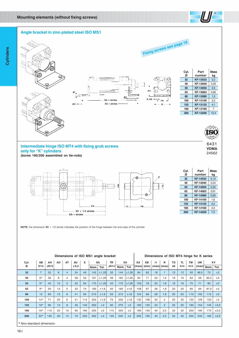
* Non-standard dimension
Dimensions of ISO MS1 angle bracket
Fixing screws see page 18
Intermediate hinge ISO MT4 with fixing grub screwsonly for “K” cylinders(bores 160/200 assembled on tie-rods)
NOTE: the dimension XV + 1/2 stroke indicates the position of the hinge between the end-caps of the cylinder.
Angle bracket in zinc-plated steel ISO MS1
SA + stroke
XA + stroke
XV + 1/2 stroke
EA + stroke
32 KF-14032 0,13
40 KF-14040 0,24
50 KF-14050 0,32
63 KF-14063 0,61
80 KF-14080 0,93
100 KF-14100 1,6
125 KF-14125 2,2
160 KF-14160 4,3
200 KF-14200 7,5
Cyl.Ø
Partnumber
Masskg
Dimensions of ISO MT4 hinge for K series
Mounting elements (without fixing screws)
stroke
stroke
32 KF-13032 0,2
40 KF-13040 0,25
50 KF-13050 0,5
63 KF-13063 0,65
80 KF-13080 1,5
100 KF-13100 2,2
125 KF-13125 4,1
160 KF-13160 7
200 KF-13200 12,4
Cyl.Ø
Partnumber
Masskg
Cyl. AB AH AO AT AU E SA TR XA EA EB I1 R TD TL TM UW XV
ø H13 JS15 ±0,2 JS14 (max) (min) (max) (max) e9 h14 h14 (max)
32 7 32 6 4 24 45 142 ±1,25 32 144 ±1,25 84 62 18 1 12 12 50 48,5 73 ±2
40 9* 36 8 4 28 52 161 ±1,25 36 163 ±1,25 94 71 20 1,5 16 16 63 59 82,5 ±2
50 9* 45 10 5 32 64 170 ±1,25 45 175 ±1,25 102 78 20 1,6 16 16 75 71 90 ±2
63 9* 50 12 5 32 74 185 ±1,6 50 190 ±1,6 108 87 26 1,6 20 20 90 84 97,5 ±2
80 12 63 15 6 41 94 210 ±1,6 63 215 ±1,6 124 96 26 1,6 20 20 110 105 110 ±2
100 14* 71 20 6 41 114 220 ±1,6 75 230 ±1,6 132 108 32 2 25 25 132 129 120 ±2
125 16* 90 15 8 45 140 250 ±2 90 270 ±2 165 125 33 2 25 25 160 154 145 ±2,5
160 18* 115 20 10 60 180 300 ±2 115 320 ±2 190 150 40 2,5 32 32 200 190 170 ±2,5
200 22* 135 30 10 70 220 320 ±2 135 345 ±2 205 165 40 2,5 32 32 250 240 185 ±2,5
Nom. Tol. Nom. Tol. Nom. Tol.
17-I
Cylin
de
rs
Mounting elements (without fixing screws)
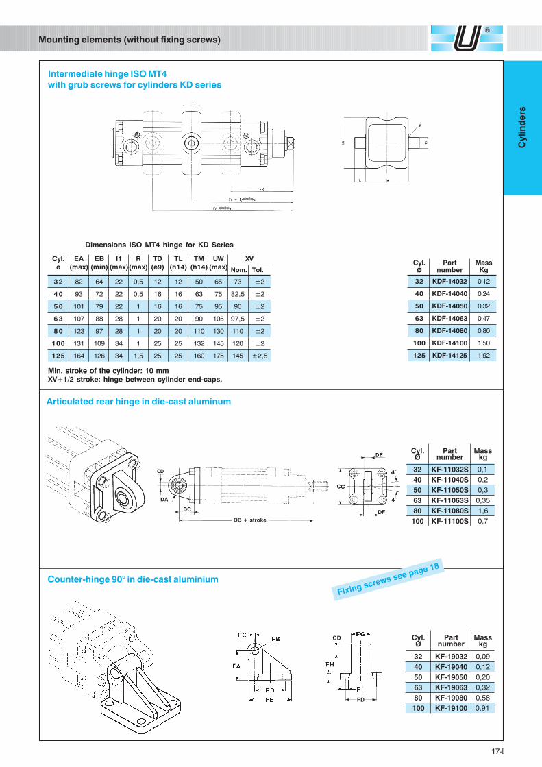
CD .lyCØ
traPrebmun
ssaMgk
23 23091-FK 90,004 04091-FK 21,005 05091-FK 02,036 36091-FK 23,008 08091-FK 85,0001 00191-FK 19,0
FD
Articulated rear hinge in die-cast aluminum
3 2 82 64 22 0,5 12 12 50 65 73 ±2
4 0 93 72 22 0,5 16 16 63 75 82,5 ±2
5 0 101 79 22 1 16 16 75 95 90 ±2
6 3 107 88 28 1 20 20 90 105 97,5 ±2
8 0 123 97 28 1 20 20 110 130 110 ±2
100 131 109 34 1 25 25 132 145 120 ±2
125 164 126 34 1,5 25 25 160 175 145 ±2,5
Intermediate hinge ISO MT4with grub screws for cylinders KD series
Min. stroke of the cylinder: 10 mmXV+1/2 stroke: hinge between cylinder end-caps.
Cyl. EA EB I1 R TD TL TM UW XVø (max) (min) (max)(max) (e9) (h14) (h14) (max)
Dimensions ISO MT4 hinge for KD Series
Nom. Tol.Cyl. Part Massø number Kg
32 KDF-14032 0,12
40 KDF-14040 0,24
50 KDF-14050 0,32
63 KDF-14063 0,47
80 KDF-14080 0,80
100 KDF-14100 1,50
125 KDF-14125 1,92
.lyCØ
traPrebmun
ssaMgk
23 S23011-FK 1,004 S04011-FK 2,005 S05011-FK 3,036 S36011-FK 53,008 S08011-FK 6,1001 S00111-FK 7,0
CD
DB + stroke
Counter-hinge 90° in die-cast aluminium
Fixing screws see page 18
stroke
stroke
18-I
Cylin
de
rs
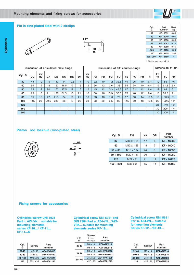
Mounting elements and fixing screws for accessories
Cylindrical screw UNI 5931
Part n. AZ4-VN--- suitable for
mounting elements
series KF-10---/ KF-11---KF-11---S
Cylindrical screw UNI 5931
Part n. AZ4-VN--- suitable
for mounting elements
Series KF-12---/KF-13---
32-40 M6 x 14 AZ4-VN0614
50-63 M8 x 16 AZ4-VN0816
80-100 M10 x 20 AZ4-VN1020
125 M12 x 25 AZ4-VN1225
Cyl.Ø
Partnumber
Screw
Cylindrical screw UNI 5931 and
DIN 7984 Part n. AZ4-VN---/AZ4-
VPA--- suitable for mounting
elements series KF-19---
M6 x 14 AZ4-VN0614
M6 x 18 AZ4-VN0618
M8 x 16 AZ4-VPA0816
M8 x 22 AZ4-VPA0822
M10 x 20 AZ4-VPA1020
M10 x 25 AZ4-VPA1025
Cyl.Ø
Partnumber
32-40
50-63
80-100
Screw2 pcs.
each type
32-40 M6 x 18 AZ4-VN0618
50-63 M8 x 22 AZ4-VN0822
80-100 M10 x 25 AZ4-VN1025
125 M12 x 35 AZ4-VN1235
Cyl.Ø
Partnumber
Screw
Dimension of articulated male hinge Dimension of 90° counter-hinge
* Pin for part nos. KF10...
Pin in zinc-plated steel with 2 circlips
Dimension of pin
.lyCØ
traPrebmun
ssaMgk
23 23081-FK 30,0
04 04081-FK 50,0
05 05081-FK 50,0
36 36081-FK 21,0
08 08081-FK 51,0
001 00181-FK 92,0
*521 52181-FK 35,1
*002-*061 06181-FK 1
Piston rod locknut (zinc-plated steel)
Ø.lyC MZ KK ROtraP
rebmun23 52,1x01M 71 6 23061-FK
04 52,1x21M 91 7 04061-FK
36÷05 5,1x61M 42 8 05061-FK
001÷08 5,1x02M 03 9 08061-FK
521 2x72M 14 21 52161-FK
002÷061 2x63M 55 41 06161-FK
Ø.lyCCC
DC9H AD BD CD ED FD
DC9H AF BF CF DF EF GF HF IF
FF8f LF MF
23 84 01 51 241 41 5,01 41 01 23 01 2,1 5,23 94 62 01 4,6 01 35 64
04 45 21 81 061 5,61 21 61 21 63 21 6,2 83 55 82 01 4,6 21 3,16 35
05 56 21 02 071 5,71 21 61 21 54 21 3,0 5,64 76 23 21 4,8 21 96 16
36 57 61 12 091 5,12 51 12 61 05 61 3,3 5,65 37 04 21 4,8 61 5,08 17
08 59 61 72 012 42 51 12 61 36 61 0,1 27 79 05 41 5,01 61 5,001 19
001 511 02 5,92 032 82 81 52 02 37 02 5,2 98 511 06 61 5,01 02 5,221 111
521 52 041 131
061 03 502 171
002 03 502 171
Fixing screws for accessories
19-I
Cylin
de
rs
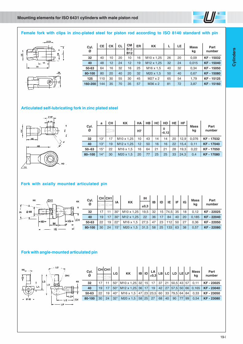
Articulated self-lubricating fork in zinc plated steel
Fork with axially mounted articulated pin
Fork with angle-mounted articulated pin
Female fork with clips in zinc-plated steel for piston rod according to ISO 8140 standard with pin
��
CL
Mounting elements for ISO 6431 cylinders with male piston rodK
K 0-0,12
IA
KK KK
KKLG°
KK
.lyCØ
EC KC LC MC21B21B
RE KK L EL ssaMgk
traPrebmun
23 04 01 02 01 61 52,1x01M 62 02 90,0 23051-FK
04 84 21 42 21 91 52,1x21M 23 42 510,0 04051-FK
36-05 46 61 23 61 52 5,1x61M 04 23 43,0 05051-FK
001-08 08 02 04 02 23 5,1x02M 05 04 76,0 08051-FK
521 011 03 55 03 54 2x72M 56 45 97,1 52151-FK
002-061 441 53 07 53 75 2x63M 18 27 78,3 06151-FK
.lyCØ
a HC KK AH BH CH DH EH FHssaM
gktraP
rebmun7H
23 °31 71 52,1x01M 01 34 41 41 02 9,21 670,0 23071-FK
04 °31 91 52,1x21M 21 05 61 61 22 4,51 11,0 04071-FK
36–05 °51 22 5,1x61M 61 46 12 12 82 3,91 22,0 05071-FK
001–08 °41 03 5,1x02M 02 77 52 52 33 3,42 4,0 08071-FK
.lyCØ
HC 1HCAI KK
HI
3,0±BI DI EI FI GI
ssaMgk
traPrebmun
23 71 11 °03 52,1x01M 5,91 23 51 5,47 53 81 21,0 52022-FK
04 91 71 °03 52,1x21M 22 63 71 48 04 02 581,0 04022-FK
36-05 22 91 °22 5,1x61M 5,72 74 32 211 05 72 63,0 05022-FK
001-08 03 42 °51 5,1x02M 5,13 85 52 331 36 83 75,0 08022-FK
.lyCØ
HC 1HCGL KK BI DI
AL± 3,0
BL CL DL EL FLssaM
gktraP
rebmun
23 71 11 °05 52,1x01M 23 51 71 73 12 5,05 34 75 11,0 52032-FK
04 91 71 °05 52,1x21M 63 71 91 24 72 5,75 05 66 561,0 04032-FK
36-05 22 91 °04 5,1x61M 74 32 5,32 06 33 5,97 46 48 33,0 05032-FK
001-08 03 42 °23 5,1x02M 85 52 72 86 04 09 77 99 45,0 08032-FK