Embed Size (px)
Citation preview
1
Unidirectional Protection Strategy forMulti-terminal HVDC Grids
Ataollah Mokhberdoran, Nuno Silva, Helder Leite and Adriano Carvalho
Abstract—Protection issue is identified as the main drawbackof emerging multi-terminal HVDC grids. Multi-terminal HVDCgrid demands fast short circuit fault current interruption. FastDC circuit breakers as a promising solution can be implementedas either bidirectional or unidirectional devices. In addition toless implementation cost, the unidirectional DC circuit breakershave less power losses as compared to the bidirectional devices.A protection strategy for multi-terminal HVDC grid based onthe unidirectional breaking devices is discussed and assessed inthis paper. The performance of unidirectional protection strategyis examined under different fault scenarios in a detailed four-terminal MMC-HVDC grid model. Furthermore, the impacts ofunidirectional protection strategy on power converters and alsocurrent interruption and surge arrester ratings of the DC circuitbreakers are discussed.
Index Terms—DC circuit breaker, HVDC, Protection Device,Voltage Source Converter (VSC), Short-circuit.
TRANSACTIONS ON ENVIRONMENT AND ELECTRICAL ENGINEERING ISSN 2450-5730 Vol 1, No 4 (2016)© Ataollah Mokhberdoran, Nuno Silva, Helder Leite and Adriano Carvalho
I. INTRODUCTION
INCREASING penetration of the clean energy resources hasled to a demand for development of more efficient ways to
transmit bulk amount of electrical energy over long distances.As a solution, high voltage direct current (HVDC) transmis-sion technology has been employed by different project devel-opers. Large offshore wind farms and onshore AC systems canbe interconnected through multi-terminal HVDC (MT-HVDC)grid in order to share the harvested energy between variousgeographical areas and enhance the system reliability [1].Voltage source converter (VSC) offers several technical bene-fits for application in the future MT-HVDC grid. The VSCtechnology was introduced by conventional two-level con-verter and has evolved into multilevel converter topologies [2].Introduction of modular multilevel converter (MMC) pavedthe way for the application of VSC in HVDC transmissionsystems. Recently, different variants of the half-bridge MMChave been developed and employed in HVDC industry [3].The conventional VSCs and the half-bridge MMC topologiesare highly vulnerable against DC side short circuit fault due tobehavior of IGBTs’ antiparallel diodes. Although full-bridgeMMCs and other fault-tolerant converters can solve this issue,their power losses and lack of protection selectivity havebeen identified as their application drawbacks. Moreover, theseconverters have not been tested practically in full-scale, yet [1].
The research leading to these results has received funding from thePeople Programme (Marie Curie Actions) of the European Unions SeventhFramework Programme (FP7/2007-2013) under REA grant n 317221.
Ataollah Mokhberdoran and Nuno Silva are with EFACEC Energia, S.A,Un. Switchgear and Automation, Rua Frederico Ulrich, PO Box 3078 4471-907, Maia, Portugal (e-mail: [email protected]). Ataollah Mokhberdoran,Helder Leite and Adriano Carvalho are with the Department of Electricaland Computer Engineering of University of Porto, Portugal.
HVDC circuit breaker (DCCB) as a promising solution maysolve the protection problem in the MT-HVDC grids [1], [4],[5], [6]. Fast DCCBs can be categorized as hybrid DC circuitbreakers (HCBs) and solid-state DC circuit breakers (SSCBs).The SSCBs can interrupt the fault current in tens of micro-seconds whereas the interruption time in HCB is expected tobe less than 3 ms [4], [5], [3]. Although the HCB interruptsthe current fast enough and has acceptable power losses, itsrealization cost for MT-HVDC grid can be expensive due tothe large number of required semiconductor switches [7].DCCBs are usually considered to be bidirectional and henceinterrupt the current in their forward and backward directions[4]. Unidirectional DCCBs (UCBs) conduct the current in theirforward and backward directions whereas interrupts the currentonly in one direction. The application of a unidirectional SSCBin a point-to-point DC connection is investigated in [8] anda unidirectional current releasing DCCB has been proposedin [9]. The protection of radial offshore DC grid using UCBshas also been studied [10]. The main concern regarding theapplication of UCB in the MT-HVDC grid is its inability ininterrupting the fault current flowing in its backward directionas it may occur in a DC bus short circuit fault scenario.In this paper, a protection strategy based on the unidirec-tional HCBs (UHCB) is suggested for MT-HVDC grid. Thesuggested strategy tries to overcome the main drawback ofUHCB. Protection logics for DC bus and transmission linefaults are investigated. The performance of suggested strategyis examined through different fault scenarios in a four-terminalHVDC grid model. For DC bus fault scenario, two DCCBtripping schemes are considered. Moreover, the superioritiesand limitations of unidirectional protection of the MT-HVDCgrid are assessed. The impacts of suggested strategy on theMT-HVDC grid elements and the HCB are also studied.
II. TYPICAL PROTECTION STRATEGY
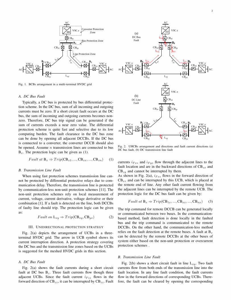
Three different protection strategies for the MT-HVDC gridsare identified: 1) handshaking approach with AC breakers,2) fault-tolerant converters with disconnector switches, 3)fast fault identification relays with fast DCCBs [1]. In thispaper, the third protection strategy together with the HCBsare considered. The HCBs can be placed at ends of eachtransmission line and also at DC side of converters. Fig. 1shows the typical bidirectional DCCBs (BCBs) arrangementand the protection zones in a three-terminal HVDC grid. CBxy
represents the DCCB attached to line Lxy close to bus Bx.Also, CBxx represents the DCCB attached to VSCx at busBx.
2
AC AC
AC
Converter Protection
Zone
Bus Protection Zone
Line Protection Zone
VSC xByCByz
CByx
CByyCBxx
CBxz
CBxy
Bx
Lxy
CBzx
VSC y
VSC z
CBzz
CBzy
Bz
Fig. 1. BCBs arrangement in a multi-terminal HVDC grid
A. DC Bus Fault
Typically, a DC bus is protected by bus differential protec-tion scheme. In the DC bus, sum of all incoming and outgoingcurrents must be zero. If a short circuit fault occurs at the DCbus, the sum of incoming and outgoing currents becomes non-zero. Therefore, DC bus trip signal can be generated if thesum of currents exceeds a near zero value. The differentialprotection scheme is quite fast and selective due to its lowcomputing burden. The fault clearance in the DC bus zonecan be done by opening all adjacent DCCBs. If the DC busis connected to a converter, the converter DCCB should alsobe opened. Assume n transmission lines are connected to busBx. The protection logic can be given as (1).
Fault at Bx ⇒ Trip(CBx1, ...,CBxx, ...,CBxn) (1)
B. Transmission Line Fault
When using fast protection schemes transmission line can-not be protected by differential protective relays due to com-munication delay. Therefore, the transmission line is protectedby communication-less non-unit protection schemes [11]. Thenon-unit protection schemes rely on local measurement ofcurrent, voltage, current derivative, voltage derivative or theircombination [1]. If a fault is detected on the line, both DCCBsof faulty line should trip. The protection logic can be givenas:
Fault on Lxy ⇒ Trip(CBxy,CByx) (2)
III. UNIDIRECTIONAL PROTECTION STRATEGY
Fig. 2(a) depicts the arrangement of UCBs in a three-terminal HVDC grid. The arrow in UCB symbol shows itscurrent interruption direction. A protection strategy coveringthe DC bus and the transmission line zones based on the UCBsis suggested for the meshed HVDC grids in this section.
A. DC Bus Fault
Fig. 2(a) shows the fault currents during a short circuitfault at DC bus Bz . Three fault currents flow though threeadjacent UCBs. Since the fault current iFzz flows in theforward direction of CBzz , it can be interrupted by CBzz . Fault
VSC x
AC AC
By
CByz
CByx
CByyCBxxCBxz
CBxy
Bx
Lxy
CBzx
AC
VSC y
VSC z
CBzz
CBzy
Bz
iFzz
iFxz iFyz
iFxz iFyz
VSC x
AC AC
ByCByz
CByx
CByyCBxx
CBxz
CBxy
Bx
Lxy
CBzx
AC
VSC y
VSC z
CB zz
CBzy
Bz
iFxy iFyx
(b)
DC Line
Fault
(a)
DC Bus
Fault
Fig. 2. UHCBs arrangement and directions and fault current directions (a)DC bus fault, (b) DC transmission line fault
currents iFxz and iFyz flow through the adjacent lines to thefault location and are in the backward directions of CBzx andCBzy and cannot be interrupted by them.As shown in Fig. 2(a), iFxz flows in the forward direction ofCBxz and can be interrupted by this UCB, which is placed atthe remote end of line. Any other fault current flowing fromthe adjacent lines can be interrupted by the remote UCB. Theprotection logic for the DC bus fault can be given by:
Fault at Bx ⇒ Trip(CB1x, ...,CBxx, ...,CBnx) (3)
The trip command for remote DCCB can be generated locallyor communicated between two buses. In the communication-based method, fault detection is done locally in the faultedbus and the trip command is communicated to the remoteDCCBs. On the other hand, the communication-less methodrelies on the fault detection at the remote buses. A fault at Bx
can be detected by the remote DCCBs at the other buses ofsystem either based on the non-unit protection or overcurrentprotection schemes .
B. Transmission Line Fault
Fig. 2(b) shows a short circuit fault in line Lxy . Two faultcurrents flow from both ends of the transmission line into thefault location. In any line fault condition, the fault currentsflow in the forward directions of corresponding UCBs. There-fore, the fault can be cleared by opening the corresponding

3
LCSUFD
Main Breaker
Surge Arrestor
DC Bus
Side
Line
Side
L
LCSUFD
Main Breaker
Surge Arrestor
DC Bus
Side
Line
Side
L
(a) (b)
iCB iLCS
Fig. 3. Hybrid DC circuit breaker (a) typical HCB, (b) UHCB
UCBs. Unidirectional protection logic for transmission linefault is similar to (2).
IV. HYBRID DC CIRCUIT BREAKER
A. Typical Hybrid DC Circuit Breaker
The configuration of a typical HCB is depicted in Fig.3(a) [12]. The main current conduction path contains a fastmechanical disconnector switch (UFD) in series with the loadcommutation switch (LCS) [5], [12]. The LCS is not requiredto block the nominal voltage and therefore, it has a lowervoltage rating and can be realized by series connection offew semiconductor switches. Hence, the HCB has reasonablepower dissipation whereas it is able to interrupt DC faultcurrent quickly (around 2.5 ms) [5]. The parallel solid-statebranch is the main breaker unit (MBU) during the fault condi-tion. Voltage rating of the main breaker unit can be identifiedbased on the transient recovery voltage (TRV) of the circuitbreaker, which is usually limited by the reference voltageof surge arrester branch [12]. In order to allow bidirectionalcurrent flow and also bidirectional fault current interruptionthe semiconductor switches are connected in anti-series.
B. Unidirectional Hybrid DC Circuit Breaker
The topology of a unidirectional hybrid DC circuit breaker(UHCB) for the positive pole of HVDC system is depictedin Fig. 3(b). In the UHCB topology, two anti-series semi-conductor switches are replaced by one switch. Therefore,the UHCB is only able to interrupt the fault current inthe transmission line side. The normal power flow can bemaintained in both forward and backward directions due topresence of antiparallel diodes. The UHCB requires half thenumber of semiconductor switches in its MBU as comparedto the typical HCB [13].The operation principles of UHCB for the transmission linefault are similar to the typical HCB. However, due to conduc-tion of antiparallel diodes in the LCS unit of UHCB, similaroperation sequence cannot be applied for the DC bus fault.Suggested operation flowchart for the UHCB is shown in Fig.14. In the flowchart, iLCS and iCB represent the LCS unitcurrent and UHCB current as it is illustrated in Fig. 3(b).In case of a line fault iLCS is positive and therefore UHCBcan activate the MBU for fault interruption. When iLCS isnegative, it means that the fault current flows in the backwarddirection of the UHCB. This case happens for UHCBs attachedto a faulty DC bus. In this case, the LCS unit should be openedand commutate whole the fault current into the antiparalleldiodes of MBU. Thereafter, the UFD can be opened. Note
MMC3 MMC4
L14L
L24
L34
I13
CB12
CB14
CB13
CB42CB31
CB21
CB24
CB41
CB43
CB34
MMC1 MMC2L12CB11
CB33CB44
CB22
M
100 km
200 km
200 km
150 km
100 km
1
B1B2
B3 B4
13
AC
Grid
AC
Grid
Fig. 4. Test multi-terminal HVDC grid
LL
Trip
Rv
cbsTe Trip
Rv
LL
cbsTe
D(a) (b)
Fig. 5. Aggregated models (a) typical HCB, (b) UHCB
that the UHCB still conducts the fault current in its backwarddirection through the antiparallel diodes of MBU until the faultcurrent is interrupted by the remote UHCB.
V. TEST SYSTEM
A. Meshed HVDC Grid
A four-terminal meshed HVDC grid model, which wasproposed in [14] is used in this study. The system configurationis shown in Fig. 4. The studied model represents a cable-basedmeshed HVDC grid. The investigated system has a symmetricmonopole HVDC configuration and includes four half-bridgeMMCs. The MMCs are modeled by a continuous modelingapproach with antiparallel diodes representing the blockingcapability of the MMCs [14].In the normal condition, MMCs 1 and 2 inject almost 700MW into the grid and MMCs 3 and 4 absorb 600 and 800MW, respectively. The blocking current threshold of MMCsis set to 3.2 kA in order to observe the MMC behavior withoutblocking during sever fault conditions. The parameters of four-terminal grid are illustrated in Table II.
B. DC Cable
HVDC transmission lines are modeled based on the XLPEinsulated cable using frequency dependent modeling approach.The cable cross-sections and properties of material are illus-trated in Fig. 15 and Table III, respectively [15].
C. Circuit Breaker Model
Since the internal operation of DCCB is not the subjectof this paper, the aggregated models of HCB and UHCBare used. Fig. 5(a) and (b) depict the aggregated models ofHCB and UHCB, respectively. As shown in Fig. 5(b) theUHCB model is derived from HCB model by adding one
4
0 2 4 6 8 10-2
0
2
4
6
8(a) CB
13
Fault on L13
Curr
ent
(kA
)
0 2 4 6 8 10-2
0
2
4
6
8(b) CB
31
Fault on L13
0 2 4 6 8 10-2
0
2
4
6
8(c) CB
12
Fault on L12
Time (ms)0 2 4 6 8 10
-2
0
2
4
6
8(d) CB
21
Fault on L12
0 2 4 6 8 10-2
0
2
4
6
8(e) CB
14
Fault on L14
0 2 4 6 8 10-2
0
2
4
6
8
(f) CB41
Fault on L14
HCB
UHCB
tbr
tid
tid
tbr
tid
tbr
tid
tbr
tbr
tid
tbr
tid
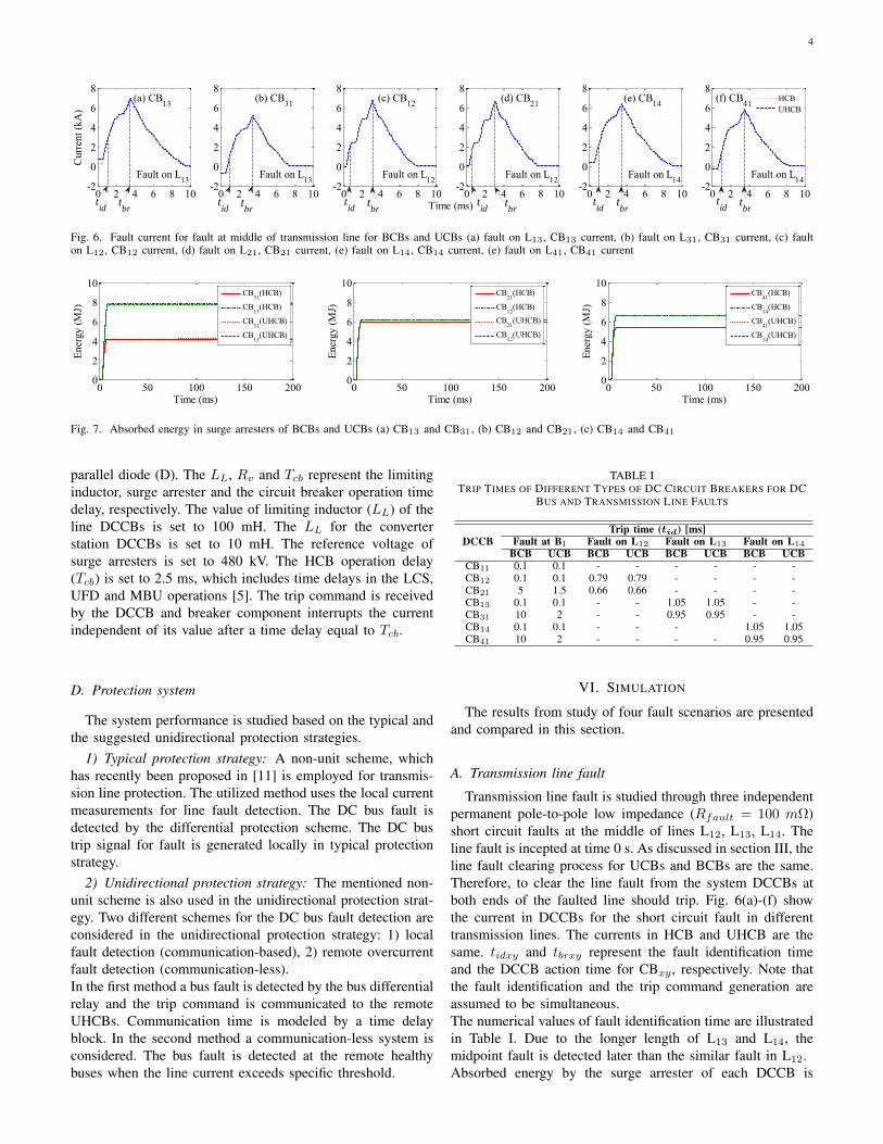
Fig. 6. Fault current for fault at middle of transmission line for BCBs and UCBs (a) fault on L13, CB13 current, (b) fault on L31, CB31 current, (c) faulton L12, CB12 current, (d) fault on L21, CB21 current, (e) fault on L14, CB14 current, (e) fault on L41, CB41 current
0 50 100 150 200
0
2
4
6
8
10
Time (ms)
Ener
gy (
MJ)
CB21
(HCB)
CB12
(HCB)
CB21
(UHCB)
CB12
(UHCB)
0 50 100 150 2000
2
4
6
8
10
Ener
gy (
MJ)
Time (ms)
CB31
(HCB)
CB13
(HCB)
CB31
(UHCB)
CB13
(UHCB)
0 50 100 150 2000
2
4
6
8
10
Ener
gy (
MJ)
Time (ms)
CB41
(HCB)
CB14
(HCB)
CB41
(UHCB)
CB14
(UHCB)
Fig. 7. Absorbed energy in surge arresters of BCBs and UCBs (a) CB13 and CB31, (b) CB12 and CB21, (c) CB14 and CB41
parallel diode (D). The LL, Rv and Tcb represent the limitinginductor, surge arrester and the circuit breaker operation timedelay, respectively. The value of limiting inductor (LL) of theline DCCBs is set to 100 mH. The LL for the converterstation DCCBs is set to 10 mH. The reference voltage ofsurge arresters is set to 480 kV. The HCB operation delay(Tcb) is set to 2.5 ms, which includes time delays in the LCS,UFD and MBU operations [5]. The trip command is receivedby the DCCB and breaker component interrupts the currentindependent of its value after a time delay equal to Tcb.
D. Protection system
The system performance is studied based on the typical andthe suggested unidirectional protection strategies.
1) Typical protection strategy: A non-unit scheme, whichhas recently been proposed in [11] is employed for transmis-sion line protection. The utilized method uses the local currentmeasurements for line fault detection. The DC bus fault isdetected by the differential protection scheme. The DC bustrip signal for fault is generated locally in typical protectionstrategy.
2) Unidirectional protection strategy: The mentioned non-unit scheme is also used in the unidirectional protection strat-egy. Two different schemes for the DC bus fault detection areconsidered in the unidirectional protection strategy: 1) localfault detection (communication-based), 2) remote overcurrentfault detection (communication-less).In the first method a bus fault is detected by the bus differentialrelay and the trip command is communicated to the remoteUHCBs. Communication time is modeled by a time delayblock. In the second method a communication-less system isconsidered. The bus fault is detected at the remote healthybuses when the line current exceeds specific threshold.
TABLE ITRIP TIMES OF DIFFERENT TYPES OF DC CIRCUIT BREAKERS FOR DC
BUS AND TRANSMISSION LINE FAULTS
DCCBTrip time (tid) [ms]
Fault at B1 Fault on L12 Fault on L13 Fault on L14
BCB UCB BCB UCB BCB UCB BCB UCBCB11 0.1 0.1 - - - - - -CB12 0.1 0.1 0.79 0.79 - - - -CB21 5 1.5 0.66 0.66 - - - -CB13 0.1 0.1 - - 1.05 1.05 - -CB31 10 2 - - 0.95 0.95 - -CB14 0.1 0.1 - - - 1.05 1.05CB41 10 2 - - - - 0.95 0.95
VI. SIMULATION
The results from study of four fault scenarios are presentedand compared in this section.
A. Transmission line fault
Transmission line fault is studied through three independentpermanent pole-to-pole low impedance (Rfault = 100 mΩ)short circuit faults at the middle of lines L12, L13, L14. Theline fault is incepted at time 0 s. As discussed in section III, theline fault clearing process for UCBs and BCBs are the same.Therefore, to clear the line fault from the system DCCBs atboth ends of the faulted line should trip. Fig. 6(a)-(f) showthe current in DCCBs for the short circuit fault in differenttransmission lines. The currents in HCB and UHCB are thesame. tidxy and tbrxy represent the fault identification timeand the DCCB action time for CBxy , respectively. Note thatthe fault identification and the trip command generation areassumed to be simultaneous.The numerical values of fault identification time are illustratedin Table I. Due to the longer length of L13 and L14, themidpoint fault is detected later than the similar fault in L12.Absorbed energy by the surge arrester of each DCCB is

5
0 5 10 15 20-8
-6
-4
-2
0
2 (a) CB12
Cu
rren
t (k
A)
0 5 10 15 20-2
0
2
4
6
8(b) CB
21
0 5 10 15 20-6
-4
-2
0
2
(c) CB13
HCB
UHCB1
UHCB2
0 5 10 15 20-2
0
2
4
6
8(d) CB
31
Cu
rren
t (k
A)
0 5 10 15 20-6
-4
-2
0
2 (e) CB14
Time (ms)0 5 10 15 20
-2
0
2
4
6
8(f) CB
41
tbr,B
tid,B
tid,U1
tbr,B
tid,B
tid,U1
tbr,U2
tid,B
tbr,B
tid,U1
tbr,U2
tid,U2
tbr,U1
tid,U2
tbr,U2
tbr,U1
tid,U2
tbr,U1
Fig. 8. Current in DCCB during fault at bus (B1) for BCBs and UCBs (a) CB12, (b) CB21, (c) CB13, (d) CB31, (e) CB14, (f) CB41
0 50 100 150 2000
2
4
6
8
10
En
erg
y
(MJ)
(a) CB21
(HCB)
CB12
(HCB)
CB21
(UHCB1)
CB12
(UHCB1)
CB21
(UHCB2)
CB12
(UHCB2)
0 50 100 150 2000
2
4
6
8
10
Time (ms)
En
erg
y
(MJ)
(b) CB31
(HCB)
CB13
(HCB)
CB31
(UHCB1)
CB13
(UHCB1)
CB31
(UHCB2)
CB13
(UHCB2)
0 50 100 150 2000
2
4
6
8
10
En
erg
y
(MJ)
(c) CB41
(HCB)
CB14
(HCB)
CB41
(UHCB1)
CB14
(UHCB1)
CB41
(UHCB2)
CB14
(UHCB2)
Fig. 9. Absorbed energy in surge arresters of BCBs and UCBs (a) CB12 and CB21, (b) CB13 and CB31, (c) CB14 and CB41
depicted in Fig. 7. The difference in dissipated energy in thesurge arresters is due to unequal interrupted fault currents incorresponding DCCBs and also different fault distances fromDCCB. DCCBs with positive pre-fault current (pre-fault andfault currents are in the same direction) reach higher currentthan the DCCB with negative pre-fault current and therefore,larger amount of energy is dissipated in their surge arresters.
B. DC bus fault
During a bus fault in the MT-HVDC grid, due to the lowinductance between the converter and fault location, high faultcurrent flows in the DC side of the converter. The fault currentmay exceed the self-protection threshold of the MMC andcause the MMC blocking. Protection of converter against DCbus faults can rely on either AC side circuit breaker or theconverter station DCCB. In this study, the MMC is protectedby a DCCB at its DC side. A permanent pole-to-pole lowimpedance (Rfault = 100 mΩ) short circuit fault is inceptedat bus B1 at time 0 s. In the typical bidirectional strategyupon fault detection by the differential scheme, CB11, CB12,CB13, CB14 should trip and disconnect the adjacent linesfrom B1. Therefore, terminal 1 of the MT-HVDC grid willbe disconnected from rest of the system and consequently, theamount of harvested energy from generation nodes of systemwill be reduced. Hence, MMC 3 and 4 will absorb less poweras compared to pre-fault conditions. The remote DCCBs ofthe adjacent lines trip after a longer time delay to disconnect
the cables from healthy DC buses.In the unidirectional protection strategy, upon fault detectionat bus B1 all adjacent UHCBs including CB11, CB12, CB13,CB14 are opened. The fault currents flow in the backward di-rections of CB12, CB13, CB14 and these UHCBs are unable tointerrupt the fault current. Therefore, based on 3, CB21, CB31
and CB41 also should trip. The DC bus fault clearing is studiedthrough two protection schemes as explained in subsectionV-D2. In the communication-based method, communicationdelay is modeled by a time delay block. The time delayblock represents sum of propagation and transmitter/receiverdelays. The propagation delay is set to 5 µs/km and thetransmitter/receiver delay is set to 1 ms [16]. The trip times ofremote DCCBs are illustrated in Table I. The second method isan overcurrent protection scheme. The overcurrent thresholdsare set to 3 kA for all lines.Fig. 8(a)-(f) show currents of all DCCBs attached to theadjacent lines for three discussed protective schemes. InFig. 8 HCB, UHCB1 and UHCB2 represents the bidirec-tional, communication-based and overcurrent-based unidirec-tional protective schemes, respectively. In addition, tid and tbrrepresent fault identification and current interruption times foreach protective scheme. Absorbed energy in the surge arresterof each DCCB is depicted in Fig. 9(a)-(c).As can been in Fig. 8, current in CB21, CB31 and CB41
reach higher values in overcurrent-based scheme as comparedto the communication-based scheme. As seen in Fig. 8(a),(c) and (e), the HCBs interrupt the bus fault current before
6
0 25 50 75 100-2
-1
0
1
2
3(a) MMC2
Cu
rren
t (k
A)
0 25 50 75 100-2
-1
0
1
2
3(b) MMC3
Time (ms)
Cu
rren
t (k
A)
0 25 50 75 100-2
-1
0
1
2
3(c) MMC4
Cu
rren
t (k
A)
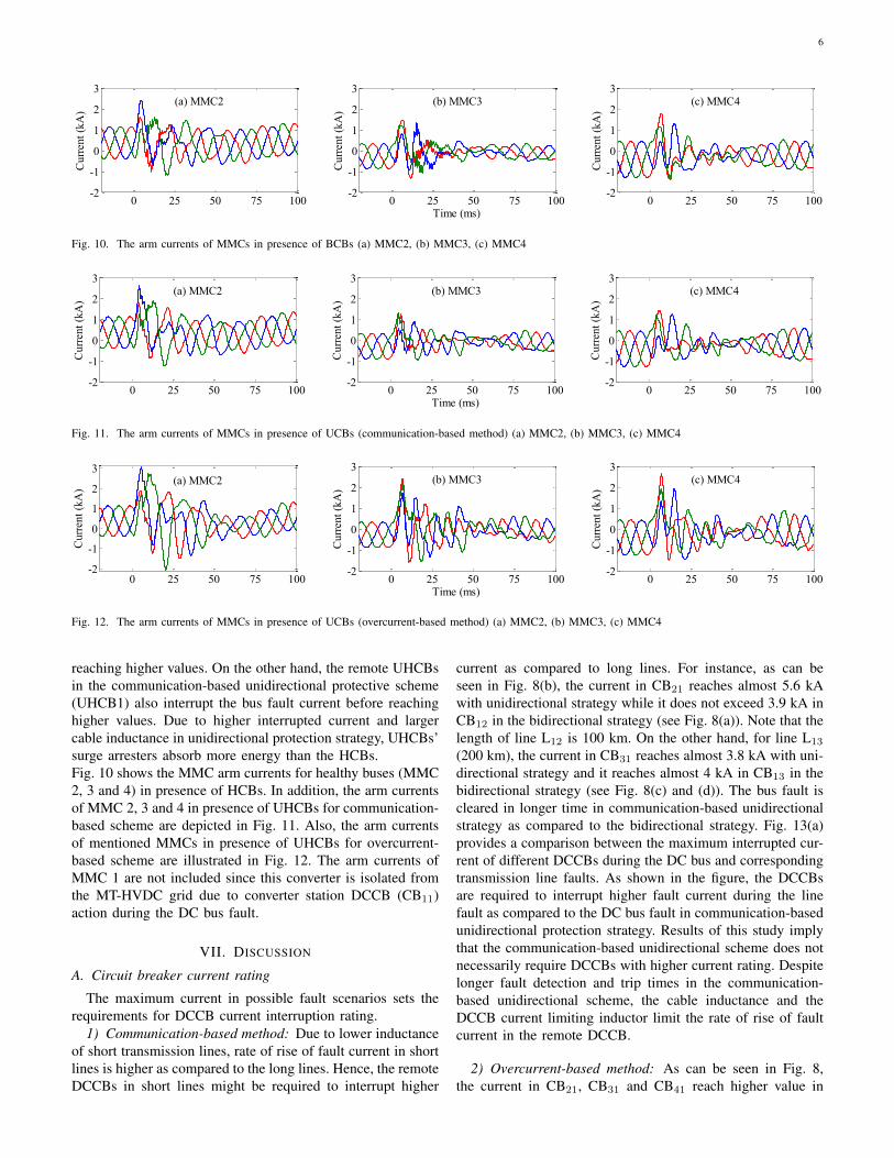
Fig. 10. The arm currents of MMCs in presence of BCBs (a) MMC2, (b) MMC3, (c) MMC4
0 25 50 75 100-2
-1
0
1
2
3(a) MMC2
Cu
rren
t (k
A)
0 25 50 75 100-2
-1
0
1
2
3(b) MMC3
Time (ms)
Cu
rren
t (k
A)
0 25 50 75 100-2
-1
0
1
2
3(c) MMC4
Cu
rren
t (k
A)
Fig. 11. The arm currents of MMCs in presence of UCBs (communication-based method) (a) MMC2, (b) MMC3, (c) MMC4
0 25 50 75 100-2
-1
0
1
2
3(a) MMC2
Curr
ent
(kA
)
0 25 50 75 100-2
-1
0
1
2
3(b) MMC3
Time (ms)
Curr
ent
(kA
)
0 25 50 75 100-2
-1
0
1
2
3(c) MMC4
Curr
ent
(kA
)
Fig. 12. The arm currents of MMCs in presence of UCBs (overcurrent-based method) (a) MMC2, (b) MMC3, (c) MMC4
reaching higher values. On the other hand, the remote UHCBsin the communication-based unidirectional protective scheme(UHCB1) also interrupt the bus fault current before reachinghigher values. Due to higher interrupted current and largercable inductance in unidirectional protection strategy, UHCBs’surge arresters absorb more energy than the HCBs.Fig. 10 shows the MMC arm currents for healthy buses (MMC2, 3 and 4) in presence of HCBs. In addition, the arm currentsof MMC 2, 3 and 4 in presence of UHCBs for communication-based scheme are depicted in Fig. 11. Also, the arm currentsof mentioned MMCs in presence of UHCBs for overcurrent-based scheme are illustrated in Fig. 12. The arm currents ofMMC 1 are not included since this converter is isolated fromthe MT-HVDC grid due to converter station DCCB (CB11)action during the DC bus fault.
VII. DISCUSSION
A. Circuit breaker current rating
The maximum current in possible fault scenarios sets therequirements for DCCB current interruption rating.
1) Communication-based method: Due to lower inductanceof short transmission lines, rate of rise of fault current in shortlines is higher as compared to the long lines. Hence, the remoteDCCBs in short lines might be required to interrupt higher
current as compared to long lines. For instance, as can beseen in Fig. 8(b), the current in CB21 reaches almost 5.6 kAwith unidirectional strategy while it does not exceed 3.9 kA inCB12 in the bidirectional strategy (see Fig. 8(a)). Note that thelength of line L12 is 100 km. On the other hand, for line L13
(200 km), the current in CB31 reaches almost 3.8 kA with uni-directional strategy and it reaches almost 4 kA in CB13 in thebidirectional strategy (see Fig. 8(c) and (d)). The bus fault iscleared in longer time in communication-based unidirectionalstrategy as compared to the bidirectional strategy. Fig. 13(a)provides a comparison between the maximum interrupted cur-rent of different DCCBs during the DC bus and correspondingtransmission line faults. As shown in the figure, the DCCBsare required to interrupt higher fault current during the linefault as compared to the DC bus fault in communication-basedunidirectional protection strategy. Results of this study implythat the communication-based unidirectional scheme does notnecessarily require DCCBs with higher current rating. Despitelonger fault detection and trip times in the communication-based unidirectional scheme, the cable inductance and theDCCB current limiting inductor limit the rate of rise of faultcurrent in the remote DCCB.
2) Overcurrent-based method: As can be seen in Fig. 8,the current in CB21, CB31 and CB41 reach higher value in

7
CB_1_2 CB_1_2 CB_2_1 CB_2_1 CB_1_3 CB_1_30
2
4
6
8
10
Cu
rren
t (k
A)
HCB
UHCB1
UHCB2
CB_1_2 CB_1_2 CB_2_1 CB_2_1 CB_1_3 CB_1_30
2
4
6
8
10
En
erg
y
(MJ)
HCB
UHCB1
UHCB2
CB12
CB21
CB13
CB31
CB14
CB41
(b)
(a)
B1
L12 B
1
L12
B1
L13
B1 L
13
L14
B1
L14
B1
B1
B1
L13 B
1
L13
B1
L14L
12 L12 L
14B1
B1
CB12
CB21
CB13
CB31
CB14
CB41
Fig. 13. (a) Maximum interrupted current and (b) absorbed energy in differentDC circuit breakers during DC bus and line faults
overcurrent-based unidirectional scheme as compared to thecurrent in CB12, CB13 and CB14 in the bidirectional and thecommunication-based unidirectional schemes. The overcurrentprotection threshold may be set to lower values in order toshorten the fault identification time if it is coordinated withthe non-unit protection scheme. As shown in Fig. 13(a), themaximum interrupted current in CB31 and CB41 is slightlyhigher for the DC bus fault with overcurrent-based methodas compared to the maximum interrupted current for corre-sponding transmission line faults. Hence, the UHCBs might berequired to interrupt higher current as compared to the HCBsdepending on the overcurrent protection parameters.
B. Surge arrester energy rating
1) Communication-based method: The amount of absorbedenergy in the surge arrester of DCCB depends on the inter-rupted current value and the fault location distance from theDCCB. The magnitude of interrupted current has higher im-pact on the amount of absorbed energy. The absorbed energy insurge arresters of DCCBs during the transmission line and theDC bus faults are compared in Fig. 13(b). As can be seen, thesurge arresters of UHCBs dissipate lower amount of energyduring DC bus fault in communication-based unidirectionalmethod as compared to corresponding transmission line fault.Note that the amount of absorbed energy in CB21 during busfault is almost equal to the absorbed energy in CB12 during theline fault. These results imply that the energy rating of surgearresters for UHCBs with communication-based unidirectionalstrategy is not necessarily different than their energy rating forHCBs with the bidirectional strategy.
2) Overcurrent-based method: Due to the higher fault cur-rent during the DC bus fault in overcurrent-based method, thesurge arresters dissipate higher amount of energy as comparedto the line fault conditions (see Fig. 13(b)). Hence, thesurge arresters in UHCBs with overcurrent-based method are
required to be rated for higher energy absorption as comparedto the HCBs with the typical strategy.
C. Impact on the convertersAs seen in Fig. 10, Fig. 11 and Fig. 12, MMC 2 arm currents
reach higher values as compared to the arm currents of otherMMCs. MMC 2 is connected to the faulted bus (B1) througha 100 km cable, which is shorter than other adjacent cables.Therefore, MMC 2 is more influenced by the fault transientas compared to the other MMCs. Furthermore, as can be seenin Fig. 12(a), one of MMC 2 arm currents reaches almost3 kA, which would be higher than self-protection thresholdlevel of MMC. Although in this study MMC 2 is not blocked,the application of unidirectional protection strategy may causeblocking of the MMCs connected to the faulted bus by a shorttransmission line. This issue can be avoided by either slightincrease in the inductance of DCCBs limiting inductor or usingIGBTs with higher current capability in MMCs.
D. Impact on DCCBThe MBU and LCS in the UHCB requires half the number
of semiconductors as compared to the HCBs. For instance,an HCB with 320 kV and 9 kA voltage and current ratingsrequires 1416 IGBTs with 3.3 kV voltage rating in the MBU[7]. By applying unidirectional protection strategy this numbercan be reduced to 708 by mean of the UHCB. Due to thelarge number of required IGBTs by the HCB and consideringthe peripheral circuits and elements for each IGBT, thisreduction can significantly decrease the initial investment forimplementation of the HCBs.
VIII. FINAL REMARKS
The UHCBs show technical and economic advantagesthanks to their less initial and operational costs as comparedto the typical HCBs. A unidirectional protection strategy forMT-HVDC grid is suggested in this paper. The results ofstudy confirm that the unidirectional protection strategy canbe utilized for protection of the MT-HVDC grid.Two methods for remote DCCB tripping are considered: 1)communication-based and 2) overcurrent-based methods. Thecommunication-based method shows better performance ascompared to the overcurrent-based method.The results of comparison study for different parameters ofDCCBs imply that the current rating of DCCBs and thesize of surge arresters are not necessarily different for thebidirectional and unidirectional strategies. However, the impactof suggested strategy on all converters of the grid, particularlythe converters with shorter transmission line between themshould be analyzed. In order to avoid blocking of the MMCsat healthy buses, slight increase in DCCB limiting inductorsize or current rating of MMC’s IGBTs might be required.Application of unidirectional protection strategy may signifi-cantly reduce the number of required semiconductor switchesin the MBU of HCBs. Considering the large number ofrequired semiconductor switches by the HCB and also theperipheral circuits and elements of each semiconductor switch,this reduction can significantly decrease the initial investmentfor implementation of the HCBs.

8
APPENDIX
Line Fault
Trigger T_F
Read Trip
Com.
Turn off MBU
Trip?
I_CB >
I_Threshold
No
Yes
Yes
No
No
YesTrigger T_ch
Turn on MBU
V_Bus >=
V_Nominal
Yes
No
Read The
Voltages
Read The
Currents
Start
V_C = V_Bus
AND
I_ch=0
No
Yes
Close?
Yes
No
Read Trip
Com.
Trip?
Yes
No
No
Start
Close?
Yes
No
LCS Opened
Yes Open UFD
No
Close
Main Breaker
Yes
Commutation
Done?
Yes
Open UFD
Yes
Open
Main Breaker
Yes
Failure
No
NoNo
Open LCS
iCB = 0
iLCS > 0
iLCS = 0
iLCS = 0
Fig. 14. Unidirectional hybrid DC circuit breaker operation logic flowchart
Fig. 15. Cross-section and configuration of the XLPE insulated HVDC cable
TABLE IIFOUR-TERMINAL HVDC SYSTEM PARAMETERS [14]
Parameter Converter 1, 2, 3 Converter 4Rated power 900 MVA 1200 MVAAC grid voltage 400 kV 400 kVConverter AC voltage 380 kV 380 kVTransformer, uk 0.15 pu 0.15 puArm capacitance Carm 29.3 µF 39 µFArm reactor Larm 84.8 mH 63.6 mHArm,resistance Rarm 0.885 Ω 0.67 ΩBus filter reactor Ls 10 mH 10 mH
TABLE IIIDC CABLE DATA [15]
Layer Radius(mm)
Resistivity(m)
Rel.permeability
Rel.permittivity
(1) Core 25.2 1.72×10⁻⁸ 1 1(2) Insulator 40.2 - 1 2.3(3) Sheath 43.0 2.20×10⁻⁷ 1 1(4) Insulator 48.0 - 1 2.3(5) Armor 53.0 1.80×10⁻⁷ 10 1(6) Insulator 57.0 - 1 2.1
REFERENCES
[1] N. Chaudhuri, B. Chaudhuri, R. Majumder, and A. Yazdani, Multi-terminal direct-current grids: Modeling, analysis, and control. JohnWiley & Sons, 2014.
[2] A. Mokhberdoran and A. Ajami, “Symmetric and asymmetric designand implementation of new cascaded multilevel inverter topology,” IEEETransactions on Power Electronics, vol. 29, no. 12, pp. 6712–6724, Dec2014.
[3] A. Mokhberdoran, A. Carvalho, N. Silva, H. Leite, and A. Carrapatoso,“Application study of superconducting fault current limiters in meshedhvdc grids protected by fast protection relays,” Electric Power SystemsResearch, vol. 143, pp. 292 – 302, 2017.
[4] A. Mokhberdoran, A. Carvalho, H. Leite, and N. Silva, “A reviewon hvdc circuit breakers,” in Renewable Power Generation Conference(RPG 2014), 3rd, Sept 2014, pp. 1–6.
[5] J. Hafner and B. Jacobson, “Proactive hybrid hvdc breakers - a keyinnovation for reliable hvdc grids,” in Electric system of the future -Integrating supergrids and microgrids international symposium, Italy,Sept 2011, pp. 1–8.
[6] B. Geebelen, W. Leterme, and D. V. Hertem, “Analysis of dc breakerrequirements for different hvdc grid protection schemes,” in AC and DCPower Transmission, 11th IET International Conference on, Feb 2015,pp. 1–7.
[7] G. Liu, F. Xu, Z. Xu, Z. Zhang, and G. Tang, “Assembly hvdc breakerfor hvdc grids with modular multilevel converters,” IEEE Transactionson Power Electronics, vol. PP, no. 99, pp. 1–1, 2016.
[8] K. Sano and M. Takasaki, “A surgeless solid-state dc circuit breakerfor voltage-source-converter-based hvdc systems,” IEEE Transactionson Industry Applications, vol. 50, no. 4, pp. 2690–2699, July 2014.
[9] A. Mokhberdoran, A. Carvalho, N. Silva, H. Leite, and A. Carrapatoso,“A new topology of fast solid-state hvdc circuit breaker for offshorewind integration applications,” in Power Electronics and Applications(EPE’15 ECCE-Europe), 2015 17th European Conference on, Sept2015, pp. 1–10.
[10] D. Jovcic, M. Taherbaneh, J. P. Taisne, and S. Nguefeu, “Offshore dcgrids as an interconnection of radial systems: Protection and controlaspects,” IEEE Transactions on Smart Grid, vol. 6, no. 2, pp. 903–910,March 2015.
[11] S. P. Azad and D. V. Hertem, “A fast local bus current-based primary re-laying algorithm for hvdc grids,” IEEE Transactions on Power Delivery,vol. PP, no. 99, pp. 1–1, 2016.
[12] A. Hassanpoor, J. Hafner, and B. Jacobson, “Technical assessment ofload commutation switch in hybrid hvdc breaker,” IEEE Transactionson Power Electronics, vol. 30, no. 10, pp. 5393–5400, Oct 2015.
[13] A. Mokhberdoran, N. Silva, H. Leite, and A. Carvalho, “A directionalprotection strategy for multi-terminal vsc-hvdc grids,” in 2016 IEEE 16thInternational Conference on Environment and Electrical Engineering(EEEIC), June 2016, pp. 1–6.
[14] W. Leterme, N. Ahmed, J. Beerten, L. Angquist, D. V. Hertem, andS. Norrga, “A new hvdc grid test system for hvdc grid dynamicsand protection studies in emt-type software,” in AC and DC PowerTransmission, 11th IET International Conference on, Feb 2015, pp. 1–7.
[15] F. Mura, C. Meyer, and R. W. D. Doncker, “Stability analysis of high-power dc grids,” IEEE Transactions on Industry Applications, vol. 46,no. 2, pp. 584–592, March 2010.
[16] S. C. F. Behrouz A. Forouzan, Data Communications and Networking.McGraw-Hill Forouzan Networking, 2007.


![A bi-pole ± 285 kV HVDC line HVDC-VSC: transmission ...TG#08].pdf · for building multi-terminal HVDC schemes, as reversing power fl ow does not involve a change of DC polarity,](https://img.pdfslide.us/doc/110x75/5e64eaca2594e126f07d0fa9/a-bi-pole-285-kv-hvdc-line-hvdc-vsc-transmission-tg08pdf-for-building.jpg)