Embed Size (px)
DESCRIPTION
This article is focused on the droop-based DC voltage control design for multi-terminal VSC-HVDC grid systems, considering the AC and the DC system dynamics. The droop control design relies on detailed linearized models of the complete multi-terminal grid, including the different system dynamics, such as the DC grid, the AC grid, the AC connection filters and the converter inner controllers. Based on the derived linear models, classical and modern control techniques are applied to design the different controllers, including a multi-variable frequency analysis to design the grid voltage droop control. In combination with the droop control, a DC oscillation damping scheme is proposed, in order to improve the system performance. The control design is validated through simulations of a three terminal system.
Citation preview

0885-8977 (c) 2015 IEEE. Personal use is permitted, but republication/redistribution requires IEEE permission. Seehttp://www.ieee.org/publications_standards/publications/rights/index.html for more information.
This article has been accepted for publication in a future issue of this journal, but has not been fully edited. Content may change prior to final publication. Citation information: DOI10.1109/TPWRD.2015.2451531, IEEE Transactions on Power Delivery
1
DC voltage droop control design for multi-terminalHVDC systems considering AC and DC grid
dynamicsEduardo Prieto-Araujo, Graduate Student Member, IEEE, Agustı Egea-Alvarez, Member, IEEE,
Sajjad (Fekri) Fekriasl, Member, IEEE, Oriol Gomis-Bellmunt, Senior Member, IEEE
Abstract—This article is focused on the droop-based DC volt-age control design for multi-terminal VSC-HVDC grid systems,considering the AC and the DC system dynamics. The droopcontrol design relies on detailed linearized models of the completemulti-terminal grid, including the different system dynamics,such as the DC grid, the AC grid, the AC connection filtersand the converter inner controllers. Based on the derived linearmodels, classical and modern control techniques are appliedto design the different controllers, including a multi-variablefrequency analysis to design the grid voltage droop control. Incombination with the droop control, a DC oscillation dampingscheme is proposed, in order to improve the system performance.The control design is validated through simulations of a three-terminal system.
Index Terms—Offshore wind power, multi-terminal, droopcontrol, HVDC, AC and DC grid interactions.
I. INTRODUCTION
IN the North Sea, a number of wind power plants arebeing commissioned due to the abundant wind resource
and the shallow waters [1]. However, offshore installationspresent some financial and technical challenges [2], such aslong distance transmission systems required for the energy gridintegration. Currently, High Voltage Direct Current (HVDC)systems based on Voltage Source Converters (VSC) are beinginstalled for integrating the energy of individual offshore windpower plants to the main land AC grid. Moreover, as the num-ber of offshore wind farm projects to be connected to the landthrough VSC-HVDC is increasing, the idea of interconnectingthese systems in a multi-terminal grid topology to increase theflexibility of the system becomes interesting [3].
The multi-terminal VSC-HVDC grid concept poses severalchallenges as the technology of the different elements con-nected to the system is still evolving in terms of power andvoltage levels. Among other problems, the control of the DCvoltage of multi-terminal VSC-HVDC grids has become apriority, in order to ensure the overall grid system stability.
Mr. Prieto-Araujo, Dr. Egea-Alvarez and Dr. Gomis-Bellmunt are withthe Departament d’Enginyeria Electrica, Centre d’Innovacio Tecnologica enConvertidors Estatics i Accionaments (CITCEA-UPC), Universitat Politecnicade Catalunya. ETS d’Enginyeria Industrial de Barcelona, Barcelona, Spain.(e-mail: [email protected])
Dr. Fekriasl is with the Advanced Research and Technology Centre, AlstomGrid, Stafford, UK.
This work has been funded by the Spanish Ministry of Economy andCompetitiveness under the projects ENE2012-33043 and ENE2013-47296.This research was co-financed by the European Regional Development Fund(ERDF).
The operation of the DC grid employing a hierarchical schemehas been proposed in [4], considering the well-known droopas the primary control, operated together with a secondarycontrol to establish the desired power flow. In particular, thedroop control is an accepted solution to regulate the DCgrid voltage fast, also allowing to establish a power sharingbetween the different converters connected to the grid [5].Different implementations of the droop control, mainly currentor power based, can be found in the literature [6]. Regardingthe controller design, it has been addressed in different studies.In [7], the controller tuning is based on the steady statecharacteristics and the resulting power flow sharing [8]. In [9]the influence of the DC grid dynamics and DC grid operationallimitations are considered during the design stage. In [10] thedroop control is tuned considering the effect of the DC cabledynamics. In [11], a droop design to reduce the perturbationsof the DC system over the AC grid is explained and in [12],the droop control is designed based on a trade-off between thepower losses, the desired power flow and the minimization ofvoltage deviations.
In this work, the power-based droop control is designed con-sidering the complete multi-terminal grid dynamics, includingthe linearized DC grid and AC grid dynamics, the convertercontrollers, and a DC oscillation damping loop, expandingthe scope of previous work [9], which was mainly focusedon designing a current-based droop through a linear DC griddynamic analysis. In order to analyze the mentioned systemdynamics, a linearized model of the complete multi-terminalVSC-HVDC grid is derived. Then, based on the linear modelobtained, the system dynamics are analyzed employing multi-variable frequency methods to select suitable droop controllersfor the DC grid. The theoretical developments are validatedthrough simulations in a three-terminal grid.
The paper is organized as follows. The next section de-scribes the droop control operation of multi-terminal VSC-HVDC grids. Section III presents the derivation of the linearmodel of a generic multi-terminal HVDC grid. The controldesign methodology is described in Section IV and in SectionV, the control design strategy is applied to a three-terminalgrid. Finally, in Section VI the article conclusions are drawn.
II. MULTI-TERMINAL GRID CONTROL
A generic VSC-HVDC multi-terminal grid layout is shownin Fig. 1. The HVDC grid is built to interconnect the offshore

0885-8977 (c) 2015 IEEE. Personal use is permitted, but republication/redistribution requires IEEE permission. Seehttp://www.ieee.org/publications_standards/publications/rights/index.html for more information.
This article has been accepted for publication in a future issue of this journal, but has not been fully edited. Content may change prior to final publication. Citation information: DOI10.1109/TPWRD.2015.2451531, IEEE Transactions on Power Delivery
2
wind power plants and the main land AC grid or gridsby means of VSC power converters. Wind Farm Converters(WFC) inject the generated power from the wind power plantsto the DC grid, whereas the Grid Side Converters (GSC)regulate the DC grid voltage employing droop control [5],[13].
WFC GSC
AC Grid
WFCGSC
AC Grid
Wind
Offshore grid
OnshoreGrid
OnshoreGrid
farm
Windfarm
Figure 1. VSC-HVDC multiterminal grid
This type of controller allows to regulate the DC gridvoltage without communications among converters, being im-plemented at each of the GSCs locally. Also, droop controlallows to establish the power sharing between convertersacting over the power loop of the converter, as it is shown inFig. 2. Possible deviations of the power, can be compensatedthrough an upper secondary control [4], that could be im-plemented with communications between the grid converters(Fig. 2), acting in a slower time frame. In this work, thisupper controller is not included in the analysis, as the studyis mainly focused on the grid voltage control based on droop,considering the overall grid dynamics. The droop control law,implemented in the n different GSCs is:
P ∗ = K(E − E∗) (1)
where E is the voltage measured at the DC terminals of theGSC converter, E∗ is the voltage reference for the droop con-troller, K is the droop constant and P ∗ is the power referenceintroduced to the power loop. Based on the power set-point,the power controller (GP ) regulates the power flowing throughthe converter in order to track the DC grid voltage reference,even assuming a DC voltage error due to the proportionalnature of the droop controller. Regarding the AC voltage, itis controlled by means of an AC module voltage regulator(GU ). The outputs of the power and AC voltage regulatorsare connected to the inner conventional current loop, that willapply voltages to the AC grid by means of the power converter,in order to regulate both current references.
Dynamics of the different interconnected systems couldaffect the droop voltage regulation, such as the DC multi-terminal grid, the AC grid connection points, the AC gridconverter filter, the power and voltage controllers or the currentinner control. Then, the design of the droop voltage controlshould be performed considering the mentioned dynamics inorder to ensure a proper control performance. To do so, in thiswork a complete linear model of the multi-terminal grid is
vqd*cvqdc Converter
iqdc
Em
En+1
+Kn
E-
P*iq*c
id*c
*
U*-
+
U
GP(s)
GU(s)
Currentloop
P- + nPn
ACgrid
vqd*cvqdc Converter
iqdc
+
id* E
-
P*iq*c
c*
U*-
+
U
GP(s)
GU(s)
Currentloop
P- +
1
P1
ACgrid
En
E1
Pn+1
Pm
SecondaryControl
K1
Node1
Noden
Grid
HVDC
Figure 2. Multi-terminal control structure including DC and AC dynamics
derived. Once the model is obtained, the different controllers,including the droop voltage control, are designed combiningclassical and modern control techniques.
III. SYSTEM MODELLING
In this section, the procedure to obtain a linear model of ageneric multi-terminal grid (Fig. 1), is detailed. The completemodel is divided in two parts, the AC system and the DCsystem. Regarding the AC system, the linearized equationsof a GSC connected to an AC grid are described. On theother hand, the linearized DC grid model is derived for asimple DC link and the procedure to model a larger grid isincluded. The existing link between both models is the powerconverter. It is modeled employing three voltage sources inthe AC side and a dependent current source in the DC side,without considering losses or Modular Multilevel Converter(MMC) inner dynamics.
A. AC system
In this section, the model of a VSC-HVDC converter con-nected to the grid is addressed. The converter grid connectionis performed by either an inductance (L) or an inductance andcapacitor filter (LC) depending on the application [14], [15],as it is shown in Fig. 3.
Cf
GSC
Cj
Ej
Ij
Rc Lc Rg Lg
ic abc ig
abc
u abc e abc v abc
PCC
Figure 3. Model of the converter connection to the AC grid
Regarding the AC grid connection, it is represented througha simple Thevenin equivalent. The state-space model of theconverter grid connection considering the LC filter is:
dxlcdt
= Alcxlc + Blculc (2)
where Alc and Blc are:
Alc =
−Rc
Lc−ω 1
Lc0 0 0
ω −Rc
Lc0 1
Lc0 0
− 1Cf
0 0 −ω 1Cf
0
0 − 1Cf
ω 0 0 1Cf
0 0 − 1Lg
0 −Rg
Lg−ω
0 0 0 − 1Lg
ω −Rg
Lg
(3)
0885-8977 (c) 2015 IEEE. Personal use is permitted, but republication/redistribution requires IEEE permission. Seehttp://www.ieee.org/publications_standards/publications/rights/index.html for more information.
This article has been accepted for publication in a future issue of this journal, but has not been fully edited. Content may change prior to final publication. Citation information: DOI10.1109/TPWRD.2015.2451531, IEEE Transactions on Power Delivery
3
Blc =
− 1Lc
0 0 0
0 − 1Lc
0 0
0 0 0 00 0 0 00 0 1
Lg0
0 0 0 1Lg
(4)
where Lc is the filter inductance value and Rc its parasiticresistance, ω is the frequency of the grid, Cf is the capacitanceof the capacitor filter and Lg and Rg are the inductance andresistance of the grid Thevenin equivalent. The state and inputvectors are:
xlc = (iqc , idc , u
q, ud, iqg, idg) (5)
ulc = (vq, vd, eq, ed) (6)
where iqdc are the currents flowing from the Point of CommonCoupling (PCC) to the converter, iqdg are the currents flowingto the grid, eqd are the grid voltages, uqd are the voltages atthe PCC and vqd are the voltages applied by the converter,in the synchronous reference frame. Applying linearization tothe previous equations, the state-space representation can beexpressed as:
d∆xlcdt
= Alc∆xlc + Blc∆ulc (7)
∆ylc = Clc∆xlc + Dlc∆ulc (8)
where the matrix Alc and Blc are the matrices defined in (3)and (4). Regarding, the system output equation, matrices Clc
and Dlc are:
Clc =
I6x6
0 0uq0
U0
ud0
U00 0
0 03 iqg02
3 idg02
3uq0
23ud
0
23 vqg02
3 vdg02 0 0 0 0
(9)
Dlc =
(08x4
3 iqc02
3 idc02 0 0
)(10)
where I6x6 is a 6x6 identity matrix and 08x4 is a zero matrixof 8 rows and 4 columns. The linearized state variables, inputsand outputs are:
∆ulc = (∆vq,∆vd,∆eq,∆ed) (11)
∆ylc = (∆iqc ,∆idc ,∆u
q,∆ud,∆idg,∆idg,∆U,∆Pu,∆P )
where U is the PCC voltage magnitude, Pu is the powerflowing to the AC grid, P is the power flowing throughthe converter and vqd0 , uqd0 , iqdc0 , iqdg0 and U0 are the systemvariables at the linearization point. Note also that, the Parktransformation used for this system is [16]:
T(θ) =3
2
cos(θ) cos(θ − 2π3 ) cos(θ + 2π
3 )sin(θ) sin(θ − 2π
3 ) sin(θ + 2π3 )
12
12
12
(12)
B. Phase Locked Loop (PLL)
A Phase Locked Loop (PLL) system is required for ori-enting the converter controllers with the grid angle [17].The synchronous reference frame is oriented with the d-axisvoltage employing a PI regulator. The output of this controlleris the estimated frequency of the grid, which is integrated toobtain the angle for the system Park transformations. The PIregulator included in the PLL is:
Kpll =(kp−plls+ ki−pll)
s(13)
where kp−pll and ki−pll are the proportional and integral gainsof the regulator, calculated based on the amplitude of the ACvoltage and the bandwidth desired for the PLL [17]. The innerdynamics of the PLL system introduce an angle deviationbetween the real grid angle and the estimated angle, speciallyduring voltage transients. In order to introduce this effect intothe converter linear model, the PLL tracking system can belinearized as [14], [18]:
∆eθ = − kp−plls+ ki−plls2 + uq0kp−plls+ uq0ki−pll
∆ud (14)
where eθ is the angle deviation between the grid angle, andthe PLL estimated angle and uq0 is the voltage of the q axis atthe linearization point. Besides, the existing deviation betweenthe grid real and estimated angles, must be integrated into themodel variables. This effect is included as a rotation of theangle deviation between both angles. Then, two different syn-chronous reference frames variables are defined, the xqd (xq
and xd) variables corresponding to the synchronous referencecalculated from the grid angle, and the xqdc (xqc and xdc)variables related to the synchronous reference frame calculatedfrom the PLL estimated angle. The transformation Tqd
c relatesboth references:
∆xqdc = Tqdc
(∆xq,∆xd,∆eθ
)T(15)
where Tqdc is:
Tqdc =
(cos
(eθ0
)− sin
(eθ0
)− sin
(eθ0
)xq0 − cos
(eθ0
)xd0
sin(eθ0
)cos
(eθ0
)cos
(eθ0
)xq0 − sin
(eθ0
)xd0
)(16)
where eθ0 is the angle error deviation value at the linearizationpoint and xd0 and xq0 are the xqd components magnitudesaround at the linearization point. Also, the inverse transfor-mation can be defined as:
∆xqd = Tqd−1
c
(∆xqc,∆xdc,∆eθ
)T(17)
where Tqd−1
c is:
Tqd−1
c =
(cos
(eθ0
)sin
(eθ0
)cos
(eθ0
)xd0 − sin
(eθ0
)xq0
− sin(eθ0
)cos
(eθ0
)− cos
(eθ0
)xq0 − sin
(eθ0
)xd0
)(18)
C. Current control
The current loop (CL) is based on the conventional vectorcontrol strategy [19]. It is based on two different PI regulatorsGCL besides a decoupling loop, as it is shown in Fig. 4. Thecurrent loop is implemented in xqdc variables.
0885-8977 (c) 2015 IEEE. Personal use is permitted, but republication/redistribution requires IEEE permission. Seehttp://www.ieee.org/publications_standards/publications/rights/index.html for more information.
This article has been accepted for publication in a future issue of this journal, but has not been fully edited. Content may change prior to final publication. Citation information: DOI10.1109/TPWRD.2015.2451531, IEEE Transactions on Power Delivery
4
+
-
+
GP(s)
GU(s)
uqdc
Pu
U
U*
P*
uqdc
iqdcg
uqdc0
Ucalc
uqdc0
Pcalciqdcg0
GCL(s)
+-
- +
Lc
+ -
-
-
+ Lc
GCL(s)
uqc
vqd
udc
e
iq*c
id*c
idcc
iqcc
Tcqd
-1
Current loop
Power
Voltage
loop
+
-
Tcqd
e
uqd
uqd
Tcqd
e
iqdcc
iqdgiqdc
g
Tcqd
e
iqdciqdc
c
u
Figure 4. Current loop and power and voltage loops linearized structures
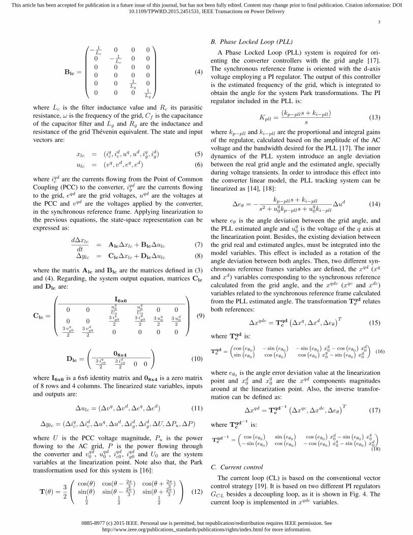
D. Power and voltage control
The power and voltage controllers are implemented by twodifferent regulators (GP and GU ), as it is shown in Fig. 4.Typically, both controllers are conventional PI regulators [5].The power and voltage feedback signals must be linear to beincluded into the model, then both magnitudes are calculatedemploying xqdc converter variables:
∆Pu =3
2
(∆iqcg u
q0 + iqg0∆uqc + ∆idcg u
d0 + idg0∆udc
)(19)
∆U =uq0∆uqc√
(uq0)2 + (ud0)2+
ud0∆udc√(uq0)2 + (ud0)2
(20)
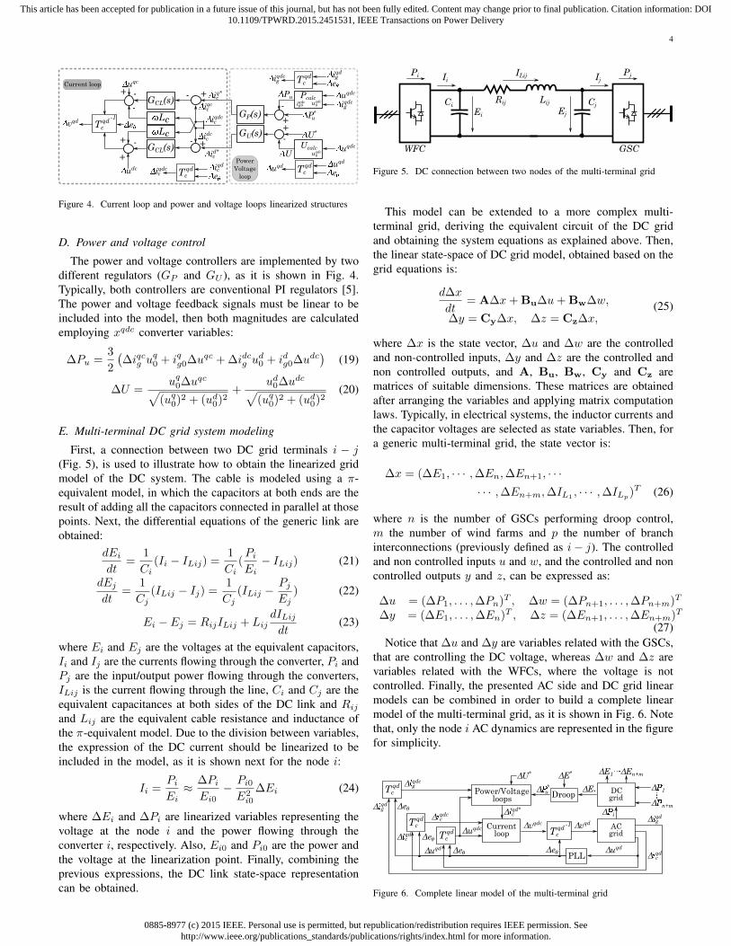
E. Multi-terminal DC grid system modeling
First, a connection between two DC grid terminals i − j(Fig. 5), is used to illustrate how to obtain the linearized gridmodel of the DC system. The cable is modeled using a π-equivalent model, in which the capacitors at both ends are theresult of adding all the capacitors connected in parallel at thosepoints. Next, the differential equations of the generic link areobtained:
dEidt
=1
Ci(Ii − ILij) =
1
Ci(PiEi− ILij) (21)
dEjdt
=1
Cj(ILij − Ij) =
1
Cj(ILij −
PjEj
) (22)
Ei − Ej = RijILij + LijdILijdt
(23)
where Ei and Ej are the voltages at the equivalent capacitors,Ii and Ij are the currents flowing through the converter, Pi andPj are the input/output power flowing through the converters,ILij is the current flowing through the line, Ci and Cj are theequivalent capacitances at both sides of the DC link and Rijand Lij are the equivalent cable resistance and inductance ofthe π-equivalent model. Due to the division between variables,the expression of the DC current should be linearized to beincluded in the model, as it is shown next for the node i:
Ii =PiEi≈ ∆Pi
Ei0− Pi0E2i0
∆Ei (24)
where ∆Ei and ∆Pi are linearized variables representing thevoltage at the node i and the power flowing through theconverter i, respectively. Also, Ei0 and Pi0 are the power andthe voltage at the linearization point. Finally, combining theprevious expressions, the DC link state-space representationcan be obtained.
WFC
Ci
Ei
GSC
Cj
Ej
Rij Lij
ILij Ii Pi Pj Ij
Figure 5. DC connection between two nodes of the multi-terminal grid
This model can be extended to a more complex multi-terminal grid, deriving the equivalent circuit of the DC gridand obtaining the system equations as explained above. Then,the linear state-space of DC grid model, obtained based on thegrid equations is:
d∆x
dt= A∆x+ Bu∆u+ Bw∆w,
∆y = Cy∆x, ∆z = Cz∆x,(25)
where ∆x is the state vector, ∆u and ∆w are the controlledand non-controlled inputs, ∆y and ∆z are the controlled andnon controlled outputs, and A, Bu, Bw, Cy and Cz arematrices of suitable dimensions. These matrices are obtainedafter arranging the variables and applying matrix computationlaws. Typically, in electrical systems, the inductor currents andthe capacitor voltages are selected as state variables. Then, fora generic multi-terminal grid, the state vector is:
∆x = (∆E1, · · · ,∆En,∆En+1, · · ·· · · ,∆En+m,∆IL1
, · · · ,∆ILp)T (26)
where n is the number of GSCs performing droop control,m the number of wind farms and p the number of branchinterconnections (previously defined as i− j). The controlledand non controlled inputs u and w, and the controlled and noncontrolled outputs y and z, can be expressed as:
∆u = (∆P1, . . . ,∆Pn)T , ∆w = (∆Pn+1, . . . ,∆Pn+m)T
∆y = (∆E1, . . . ,∆En)T , ∆z = (∆En+1, . . . ,∆En+m)T
(27)Notice that ∆u and ∆y are variables related with the GSCs,
that are controlling the DC voltage, whereas ∆w and ∆z arevariables related with the WFCs, where the voltage is notcontrolled. Finally, the presented AC side and DC grid linearmodels can be combined in order to build a complete linearmodel of the multi-terminal grid, as it is shown in Fig. 6. Notethat, only the node i AC dynamics are represented in the figurefor simplicity.
Currentloop
ΔPi
ΔU*
Δuqdc
Δeθ
ΔP*u
Tcqd
Δiqdcc
Tcqd
Δvqdc
Tcqd
-1 Δvqd
Power/Voltageloops
Δiqd*c
Δuqd Δeθ
Δeθ Δiqdc
Tcqd Δi
qdcg
Δiqdg
ACgrid
ΔE*
DroopDCgrid
ΔP1
ΔPn+m
ΔE
ΔiqdcPLL
Δuqd
Δiqdg
ΔE1 ΔEn+m
Δeθ
Figure 6. Complete linear model of the multi-terminal grid

0885-8977 (c) 2015 IEEE. Personal use is permitted, but republication/redistribution requires IEEE permission. Seehttp://www.ieee.org/publications_standards/publications/rights/index.html for more information.
This article has been accepted for publication in a future issue of this journal, but has not been fully edited. Content may change prior to final publication. Citation information: DOI10.1109/TPWRD.2015.2451531, IEEE Transactions on Power Delivery
5
IV. CONTROL DESIGN METHODOLOGY
In this section, a theoretical procedure for designing a droopcontrol for multi-terminal grids is addressed. As it is explainedin Section II, the droop control behavior not only depends onthe DC or AC grid dynamics, but also on the inner controlloops of the converter (Fig. 7). Then, a procedure to designboth the inner control loops and the droop voltage control loopis presented.
+
kGCL(s)
+
-
- +
id*
Lc
uq
+ -
-
-
+
vq
vd
PLL
E-
E
P*
Lc
GCL(s)
iq*
iqc
c
idc
c
iqdc
+
-
Pref
*
+P
U*-
+
U
T( )
GP(s)
GU(s)
ig abc
1s
-1GPLL(s)ud
T( ) uabc
Current loop
Control
systemud
Volt
age
mod
ula
tion
uqd
(uq)2+(ud)2 uqd
uqd
T( )ig
qd
+
Cf
GSC
Cj
Ej
Ij
Rc Lc Rg Lg
u abc e abc v abc
ig abc ic
abc
ig abc ic
abc
u
u
Figure 7. Converter control scheme
A. Current control loop
The inner current control is based on vector control in thesynchronous reference frame, tuned by Internal Model Control(IMC) technique [19]. Therefore, two PI regulators (GCL)plus a decoupling loop are employed to track the xqd currentreferences in a defined time, following a first order systemresponse with a time constant τ :
Kc =kps+ ki
s, kp =
Lcτ, ki =
Rcτ
(28)
The control closed loop time constant τ can be calculatedbased on the desired settling time, which physically representsthe time that the system response takes to settle within a rangeof the final value (usually ±5% or ±2% depending on thecriterion). The current loop settling time is typically selected totrack current references within a few milliseconds. Saturationsare included in the control scheme, in order not to exceed themaximum current rating of the converter.
B. Power and voltage loop
As it is shown in Fig. 7, two different controllers, one fortracking power references (GP ) and another to regulate theAC grid voltage (GU ), are introduced as an outer loop ofthe current vector control. As the power loop is receivingreferences from the droop voltage loop, fast dynamics couldbe required to respond to voltage variations in the DC grid.Therefore, the bandwidth for the outer loop controller shouldbe designed to follow relatively fast droop control outputswithout disturbing the inner current control loop. For thisreason, the AC side of the linear model of the system (Fig. 6)is employed to design GP and GU , considering the dynamicsof the inner current loop. The parameters of both controllersare calculated based on optimization robust control techniques
[15], [20]. The inputs for the optimization are basically thedesired settling time for reference tracking for both controllers,expressed as two different objective transfer functions. Then,the optimization algorithm is run to design the PI parametersbased on the frequency requirements.
C. Droop control
The droop design should be carried out considering all thedynamics of the multi-terminal system, as these affect theperformance of the controller. For this reason, the controlanalysis should employ the linear model of the multi-terminalgrid explained above, which includes the different systemsinvolved in the droop operation. The complete dynamic systemof the multi-terminal grid is depicted in Fig. 8, where thedifferent control stages of the converter can be identified.
ΔPu1
ΔE1*
K1
ΔP1 ΔPn
ΔE1 ΔEn
ΔPn+1 ΔPn+m
ΔE1 ΔEn ΔEn+mΔEn+1
ConverterAC Grid
- +
+
ΔU1*
-+ΔU1
-
Δic1q*
Δic1d*
ΔPun
ΔEn*
Kn
-+
+ΔPun
GPGU
ΔUn*
- +ΔUn
-
Δicnq*
Δicnd*
-ΔPu1
-
*
CL
e1Δ
Δy Δr Δz
Δu
DCgrid
Δw
Δuiq1 Δuiqn
Δen
ConverterAC Grid
CL
GP GU
*
ΔPu1Δ ΔPun
Figure 8. HVDC grid control scheme
Fig. 8 is redrawn in a conventional feedback structure inFig. 9, showing the control design problem to be addressed.Based on this scheme, different closed loop transfer functionmatrices can be calculated combining the converters and bothAC and DC grid dynamics:
∆e(s) = ∆y(s)−∆r(s) = (Ew(s) Er(s))∆v(s)∆uiq(s) = (U
uiqw (s) U
uiqr (s))∆v(s)
∆v(s) = (∆w(s) ∆r(s))T
∆r(s) = (∆E∗1 , · · · ,∆E∗n)T
∆uiq(s) = (∆iq∗c1 , · · · ,∆iq∗cn)T
(29)
where Er(s) and Ew(s) are the transfer function matrices,relating the droop voltage references r and the power in-troduced in the HVDC grid by the wind farms w, with thesystem voltage errors e at the controlled nodes, respectively.Analogously, Uuiq
r (s) and Uuiqw (s) relate the droop references
r and the wind farm incoming power w, with the activecurrent loop references uiq of the current loop of the differentconverters.
The different droop controller constants can be designedanalyzing the frequency response of the multi-variable systemtransfer function matrices, using the singular values represen-tation. This technique can be understood as an expansion ofthe Bode frequency representation for multi-variable systems.Basically, the specifications for the different droop controllersare the desired power sharing among the different convert-ers controlling the DC voltage, the maximum voltage errorallowed at the grid terminals and the maximum convertercurrent ratings. These requirements can be transferred as gain
0885-8977 (c) 2015 IEEE. Personal use is permitted, but republication/redistribution requires IEEE permission. Seehttp://www.ieee.org/publications_standards/publications/rights/index.html for more information.
This article has been accepted for publication in a future issue of this journal, but has not been fully edited. Content may change prior to final publication. Citation information: DOI10.1109/TPWRD.2015.2451531, IEEE Transactions on Power Delivery
6
K1
Kn0
e1
en
U1
Un
U1
Un
ic1q
icnq
ic1d*
icnd*
ic1q*
icnq*
Converter 1
0
0
AC Grid 1
Converter nAC Grid n
E1
En
**
*
DCgrid
E1
En
P1
Pn
P
Pn+m
n+1
En+1
En+m
Pu1*
0
Pun*
Pu1
Pun
GP1
GPn0
0
GU1
GUn0
0*
*
*
*
ic1d
icnd
*
*
CL
CL0
0
y z
er
w
uiq
u
Figure 9. HVDC multi-terminal grid control structure
boundaries in the multi-variable frequency response of theoverall system [9]. In order to perform the frequency analysis,the structure of the droop controller is defined as:
K =
(K1 0
. . .0 Kn
)= Kg
(q1 0. . .
0 qn
)(30)
where Kn are the droop constants implemented in each of theGSCs, Kg is a generic scale factor and q1 to qn are the weightsof the different controllers, that can be calculated based onthe power sharing [9]. Then, in order to dynamically analyzethe system, only the parameter Kg needs to be selected,assuming that the qn constants are defined based on the desiredpower sharing [7]. However, according to [21] scaling theparameter Kg , maintaining the different qn values constant,could cause deviations on the desired power sharing betweenconverters. In this article, it is assumed that this deviationscan be compensated by the secondary control [4]. However, ifthe power deviation obtained is too large, the droop designsolution could be based on performing an analysis of thecontrol dynamics, modifying the qn parameters as the Kg
introduced is changed, in order to maintain the power sharing.Assuming the previous considerations, the singular values
representation of the system transfer function matrices of thesystem can be obtained as:
σi(G(jω)) =√λi(GT (jω)G(jω)) (31)
where λi(·) is the i-th eigenvalue of the matrix. This calcu-lation shows how a system vector input is seen at the output.Specifically, for a defined frequency, the maximum singularvalue σ(G(jω)) is extremely interesting, as it shows thepossible maximum amplification that the system is applyingto an input vector oscillating at this frequency [22]. Thiscalculation could be extended for the whole range of frequen-cies, obtaining the singular values frequency representation ofa transfer function matrix. Then, assuming a defined powersharing, the control objectives can be focused on minimizingthe voltage errors without exceeding the converter currentlimitations. As it is mentioned above, these requirements canbe imposed as boundaries on the singular values frequencyresponse, that could limit the maximum and minimum values
of Kg . For example, the maximum energy of the error, causedby any input v of bounded energy, is given by:
maxv 6=0
‖e‖2‖v‖2
= maxω
σ(Tev(jω)) (32)
where ‖e‖22 =∫eT e dt is the 2-norm of e. Therefore, to
minimize the effects of the disturbance w on the voltage errore can be understood as minimizing:
σ (Ew(s) Er(s)) (33)
and to maintain the control flowing through the converterunder the defined limits can be expressed as ensuring that
σ (Uuiqw (s) Uuiq
r (s)) (34)
is bounded at the frequencies of interest.
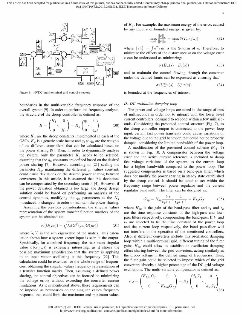
D. DC oscillation damping loop
The power and voltage loops are tuned in the range of tensof milliseconds in order not to interact with the lower levelcurrent controllers, designed to respond within a few millisec-onds. Considering the presented control structure (Fig. 7), asthe droop controller output is connected to the power loopinput, certain fast power transients could cause variations ofthe voltage due to the grid behavior, that could not be properlydamped, considering the limited bandwidth of the power loop.
A modification of the presented control scheme (Fig. 7)is shown in Fig. 10. A compensator between the voltageerror and the active current reference is included to dampfast voltage variations of the system, as the current loophas a higher bandwidth compared to the power loop. Thesuggested compensator is based on a band-pass filter, whichdoes not modify the power sharing in steady state establishedby the droop control. It should be tuned to act within thefrequency range between power regulator and the currentregulator bandwidth. The filter can be designed as:
Gbp = Kbpt1s
t1s+ 1
1
t2s+ 1= KbpGf (35)
where Kbp is the gain of the band-pass filter and t1 and t2are the time response constants of the high-pass and low-pass filters respectively, compounding the band-pass. If t1 andt2 are selected to be the time constant of the power loopand the current loop respectively, the band pass-filter willnot interfere in the operation of the mentioned controllers.Also, if different converters include this oscillation dampingloop within a multi-terminal grid, different tuning of the filtergains Kbp could allow to establish an oscillation dampingeffect sharing between the grid converters, acting similarly asthe droop voltage in the defined range of frequencies. Thus,the filter gain could be selected to impose which of the gridconverters absorbs a higher percentage of the DC grid voltageoscillations. The multi-variable compensator is defined as:
Kd =
Kbp1Gf 0. . .
0 KbpnGf
= Kf
d1Gf 0. . .
0 dnGf
(36)
0885-8977 (c) 2015 IEEE. Personal use is permitted, but republication/redistribution requires IEEE permission. Seehttp://www.ieee.org/publications_standards/publications/rights/index.html for more information.
This article has been accepted for publication in a future issue of this journal, but has not been fully edited. Content may change prior to final publication. Citation information: DOI10.1109/TPWRD.2015.2451531, IEEE Transactions on Power Delivery
7
+
K
+
E-
E
P*iqp*c
+
-
P ref
*
+
GP(s)
+
Gbp(s)iqbp*c
iq*cu
uP
Figure 10. Droop and power loop combined with the DC oscillation damping
where Kf is a generic scale factor and d1 to dn are theweights of the different compensation loops. Specifically,values from d1 to dn can be defined based on the oscillationsharing desired for each GSC, analogously to the droop powersharing parametrization. Thus, selecting the Kf constant, thecontroller becomes completely defined. In order to select thementioned parameter, the singular values of the system transferfunction matrices can be analyzed, including the damping loopin the matrix transfer functions calculations.
V. CASE STUDY
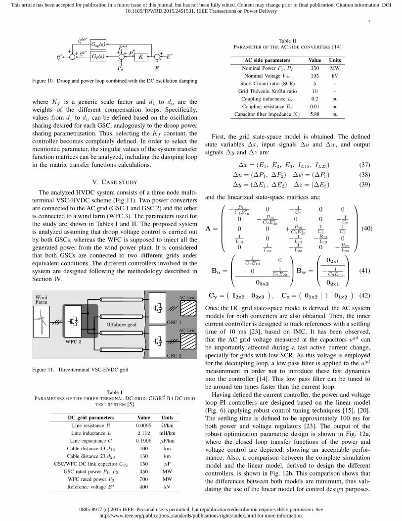
The analyzed HVDC system consists of a three node multi-terminal VSC-HVDC scheme (Fig 11). Two power convertersare connected to the AC grid (GSC 1 and GSC 2) and the otheris connected to a wind farm (WFC 3). The parameters used forthe study are shown in Tables I and II. The proposed systemis analyzed assuming that droop voltage control is carried outby both GSCs, whereas the WFC is supposed to inject all thegenerated power from the wind power plant. It is consideredthat both GSCs are connected to two different grids underequivalent conditions. The different controllers involved in thesystem are designed following the methodology described inSection IV.
WFC 3
GSC 1
AC Grid
GSC 2
AC Grid
Farm
Offshore grid
Wind
Figure 11. Three-terminal VSC-HVDC grid
Table IPARAMETERS OF THE THREE-TERMINAL DC GRID. CIGRE B4 DC GRID
TEST SYSTEM [5]
DC grid parameters Value UnitsLine resistance R 0.0095 Ω/kmLine inductance L 2.112 mH/kmLine capacitance C 0.1906 µF/km
Cable distance 13 d13 100 kmCable distance 23 d23 150 km
GSC/WFC DC link capacitor Cdc 150 µFGSC rated power P1, P2 350 MW
WFC rated power P3 700 MWReference voltage E∗ 400 kV
Table IIPARAMETER OF THE AC SIDE CONVERTERS [14]
AC side parameters Value UnitsNominal Power P1, P2 350 MWNominal Voltage Vac 195 kV
Short Circuit ratio (SCR) 5 -Grid Thevenin Xn/Rn ratio 10 -
Coupling inductance Lc 0.2 puCoupling resistance Rc 0.01 pu
Capacitor filter impedance Xf 5.88 pu
First, the grid state-space model is obtained. The definedstate variables ∆x, input signals ∆u and ∆w, and outputsignals ∆y and ∆z are:
∆x = (E1, E2, E3, IL13, IL23) (37)∆u = (∆P1, ∆P2) ∆w = (∆P3) (38)∆y = (∆E1, ∆E2) ∆z = (∆E3) (39)
and the linearized state-space matrices are:
A =
− P10
C1E210
0 − 1C1
0 0
0 − P20
C2E220
0 0 − 1C2
0 0 + P30
C3E230
1C3
1C3
1L13
0 − 1L13
−R13
L130
0 1L23
− 1L23
0 −R23
L23
(40)
Bu =
1
C1E100
0 1C2E20
03x2
Bw =
02x1
− 1C3E30
02x1
(41)
Cy =(I2x2 02x3
), Cz =
(01x2 1 01x2
)(42)
Once the DC grid state-space model is derived, the AC systemmodels for both converters are also obtained. Then, the innercurrent controller is designed to track references with a settlingtime of 10 ms [23], based on IMC. It has been observed,that the AC grid voltage measured at the capacitors uqd canbe importantly affected during a fast active current change,specially for grids with low SCR. As this voltage is employedfor the decoupling loop, a low pass filter is applied to the uqd
measurement in order not to introduce these fast dynamicsinto the controller [14]. This low pass filter can be tuned tobe around ten times faster than the current loop.
Having defined the current controller, the power and voltageloop PI controllers are designed based on the linear model(Fig. 6) applying robust control tuning techniques [15], [20].The settling time is defined to be approximately 100 ms forboth power and voltage regulators [23]. The output of therobust optimization parametric design is shown in Fig. 12a,where the closed loop transfer functions of the power andvoltage control are depicted, showing an acceptable perfor-mance. Also, a comparison between the complete simulationmodel and the linear model, derived to design the differentcontrollers, is shown in Fig. 12b. This comparison shows thatthe differences between both models are minimum, thus vali-dating the use of the linear model for control design purposes.

0885-8977 (c) 2015 IEEE. Personal use is permitted, but republication/redistribution requires IEEE permission. Seehttp://www.ieee.org/publications_standards/publications/rights/index.html for more information.
This article has been accepted for publication in a future issue of this journal, but has not been fully edited. Content may change prior to final publication. Citation information: DOI10.1109/TPWRD.2015.2451531, IEEE Transactions on Power Delivery
8
Analogously to the current loop, low pass filters are appliedto the voltage uqd and currents iqdg measurements employedfor calculating the power and voltage feedback measurements,in order to damp fast transients of the magnitudes. These lowpass filters can be also tuned around ten times faster than thecurrent loop.
4.95 5 5.05 5.1 5.15 5.2
348
350
352
354
356
Time (s)
Po
wer
(M
W)
4.95 5 5.05 5.1 5.15 5.2158
158.5
159
159.5
160
Time (s)
Vo
ltag
e (k
V)
Complete model
Linear model
b)
100
102
10480
60
40
20
0
Frequency (rad/s)
Mag
nit
ude
(dB
)
100
102
10480
60
40
20
0
Frequency (rad/s)
Mag
nit
ude
(dB
)
U*
to UP*
to P
a)
u u
Figure 12. Design output of the voltage and power loops of the converter. a)Bode representation of the closed loop transfer functions (P ∗
u to Pu and U∗
to U ). b) Power and voltage response comparison between the complete andlinear models, for a power step change.
Once the outer power and voltage loops are designed, themulti-terminal droop control is addressed. Assuming that thepower generated by the wind power plant, injected to the DCgrid by the WFC, must be shared by both GSCs, an initialparametrization is established for the controller. Then, themulti-variable droop controller, considering that GSC 1 andGSC 2 are regulating the voltage, can be defined as:
K =
(K1 00 K2
)= Kg ·
(1 00 1
)= Kg · I2 (43)
where K1 and K2 are the droop constants locally imple-mented at each of the GSCs, expressed in kW/V units.This parametrization could lead to an unequal power sharing,depending on the grid impedances and the power flow, factthat can be solved by the secondary control. Then, as the exactpower sharing is ensured by the upper control layer, this workis focused on the design of the droop control considering thedynamics of the whole multi-terminal grid. Then, based onthe linear model of the system, the transfer function matricesEw(s), Er(s), Uuiq
w (s) and Uuiqr (s) are obtained following the
structure shown in Fig. 9. Note that, the reference inputs E∗
do not introduce any voltage error in the system [9], thus thesystem analysis will only be focused on Ew(s) and Uuiq
w (s),that relate the voltage errors and the control action with thewind power input, respectively.
Next, the singular values representation of Ew(s) relatingthe GSC DC voltage errors and the power coming from thewind farm is depicted in Fig. 13a. Assuming a maximumvoltage error of a 10% of the nominal value at each terminal.The singular values representation should not exceed, in steady
state, a maximum gain of [9]:
σ(Ew(0)) ≤ ||e(0)||2||w(0)||2
= 20 log10
(√(emx1 + emx2)
P3
)=
= 20 log10
(√(4 · 105 · 0.1)2 · 2
700 · 106
)= −81.85 dB (44)
100
101
102
103
90
80
70
Frequency (rad/s)
Mag
nit
ude
(dB
)
Frequency (rad/s)
Mag
nit
ude
(dB
)
100
101
102
103
90
80
70
Kg=10 K
g=15 K
g=20 K
g=25 Units (kW/V)
a) b)
Figure 13. Singular values representation of Ew(s) (DC voltage errors - Windpower input) a) Without oscillation damping, b) With oscillation damping.
According to Fig. 13a, all the droop constants Kg depictedare able to maintain the maximum voltage error below a10% of the nominal voltage value, in steady state. However,resonance peaks are observed at relatively low frequencies,fact that could cause voltage oscillations during wind powerflow variations, specially if the wind farm power input excitesthose frequencies. In order to damp those peaks, the DCoscillation damping loop is implemented in both GSCs settingt1 and t2 at the time constants of the current and the powerloop respectively. For a first analysis, the same gain is appliedto both filters, considering a Kf equal to 1/20 A/V.
Fig. 13b shows again the frequency response of Ew(s),including the designed oscillation damping loop. This graphshows that the gain peaks have been reduced, confirming thatthe oscillation damping loop is able to improve the droopcontrol performance. Moreover, as the damping effect can beshared between the different GSC converters, Fig. 14 is drawnto show how different weights d1-d2 affect the overall gridvoltage error, as:
Kd =
(Kbp1Gf 0
0 KbpnGf
)=
(d1Gf 0
0 d2Gf
)(45)
100
101
102
103
90
80
70
Frequency (rad/s)
Mag
nit
ude
(dB
)
d1
= 0, d2
= 0
d1
= 1/80, d2
= 1/20
d1
= 1/20, d2
= 1/80
d1
= 1/20, d2
= 1/20
Kg=20 kW/V
Figure 14. Singular values representation of Ew(s) (DC voltage errors -Wind power input), for different damping loops.
Fig. 14 shows that the maximum gains, and consequentlythe maximum voltage error, are obtained disconnecting thedamping loop (d1 and d2 equal to 0). On the other hand,the minimum voltage error is achieved when both convertersinclude the same oscillation damping loop. Moreover, twointermediate cases are shown, where the damping loop ofone of the two GSC converters, has a higher filter gaincompared to the other. Both cases show a gain reduction

0885-8977 (c) 2015 IEEE. Personal use is permitted, but republication/redistribution requires IEEE permission. Seehttp://www.ieee.org/publications_standards/publications/rights/index.html for more information.
This article has been accepted for publication in a future issue of this journal, but has not been fully edited. Content may change prior to final publication. Citation information: DOI10.1109/TPWRD.2015.2451531, IEEE Transactions on Power Delivery
9
compared to the system without damping loop, revealing thatthe overall grid error can be compensated acting from differentnodes. However, one of the intermediate cases shows lowergain peaks compared to the other. This fact is caused bythe difference between the line impedances, which allows toone of the GSCs to apply a greater damping effect on theoverall grid oscillation damping. This analysis reveals that thedamping loop is not only locally affecting the node where itis implemented, but also the overall grid voltage oscillations.
From now on, it is considered that the gain of the dampingloop at both GSCs is equal (d1=d2=1). Thus, setting the gainKf , the damping controller is defined. Then, an extendedanalysis of the singular values of the transfer function Ew(s),considering several droop constants Kg and including differentoscillation damping loops Kf , is shown in Fig. 15.
100
101
102
103
95
90
85
80
75
Frequency (rad/s)
Mag
nit
ude
(dB
)
100
101
102
103
95
90
85
80
75
Frequency (rad/s)
Mag
nit
ude
(dB
)
100
101
102
103
95
90
85
80
75
Frequency (rad/s)
Mag
nit
ude
(dB
)
100
101
102
103
95
90
85
80
75
Frequency (rad/s)
Mag
nit
ude
(dB
)
Kg=10 K
g=15
Kg=20 K
g=25
Kf=1/25 K
f=1/20 K
f=1/15 K
f=1/10 f
K (kW/V)K (A/V)g
Figure 15. Singular values representation of Ew(s) (DC voltage errors -Wind power input), including damping loop, for different Kg and Kf .
Also, the singular values representation of the transfer func-tion matrix Uuiq
w (s), relating the control action (represented bythe current loop references) and the power coming from thewind farms, is depicted in Fig. 16 for several droop constantsKg and different oscillation damping loops Kf .
100
101
102
103
115
110
105
100
101
102
103
115
110
105
100
101
102
103
115
110
105
100
101
102
103
115
110
105
Frequency (rad/s)
Mag
nit
ude
(dB
)
Frequency (rad/s)
Mag
nit
ude
(dB
)
Frequency (rad/s)
Mag
nit
ude
(dB
)
Frequency (rad/s)
Mag
nit
ude
(dB
)
Kg=10 K
g=15
Kg=20 K
g=25
Kf=1/25 K
f=1/20 K
f=1/15 K
f=1/10 f
K (A/V)
K (kW/V)g
Figure 16. Singular values representation of Uuiqw (s) (Current loop references
- Wind power input), including damping loop, for different Kg and Kf .
Figs. 15 and 16 must be analyzed together in order todecide which are the most favorable constants Kg and Kf forthe system. First, analogously to the gain limitation imposed
to the frequency response of Ew(s), another limitation iscalculated for the singular values of U
uiqw (s), considering
that the maximum allowed current that could flow throughthe converter is a 110% of the nominal current value. Thiscorresponds to a gain boundary limitation of -109.74 dB.
Before analyzing the singular values, it should be mentionedthat the power loop of the WFC is considered to respond withthe same bandwidth as the GSC. Then, power disturbanceswith frequencies larger than approximately 40 rad/s will notbe introduced into the system, unless an AC fault occurs inthe wind farm. In that case, the WFC could reduce the powerinjected to the DC grid rapidly to zero.
Fig. 15 shows that constants Kg greater than 15 kW/Vwith Kf also greater than 1/15 A/V allow to operate thesystem maintaining the voltage error under the defined 10%.Besides, as the system wind power disturbances are limitedin bandwidth, the error can even be maintained below a 5%.To achieve this goal, the GSCs need to inject current to thegrid (control action) without exceeding its own limits. Then,the singular values gains of Uuiq
w (s), shown in Fig. 16, shouldbe maintained below the calculated boundary. It can be seenthat all curves exceed the maximum allowed gain at a certainfrequency, which is not desirable from the converter operationperspective. Specifically, certain combinations of Kg and Kf
present gain curves that are crossing the defined boundarybelow the power loop bandwidth (40 rad/s), which could leadthe converter to operate out of its limits. For this reason,constants Kg higher than 20 kW/V should not be includedin the control system. Finally, in order to select the controllerconstants, among the different possible available combinations,the defined criterion is to minimize the voltage error, whilemaintaining the converter operating within its current limits.Based on this criteria, constants Kg of 20 kW/V and Kf of1/20 A/V are able to securely operate the system minimizingthe error, without exceeding the current limitation.
Once the droop control design is concluded, Matlab-Simulinkr simulations of the three-terminal grid (Fig. 11) arecarried out to validate the obtained results. Figs. 17 and 18show the voltage droop control response (performed by theGSCs) to a nominal power input from the WFC from 0 MW to700 MW at 2 s. During the simulation, the power reference ofboth GSC Pref is maintained at zero, in order to observe howthe designed distributed droop controller is able to control theoverall DC voltage without communications. The cable modelemployed is a π-equivalent model with 100 sections. Fig. 17shows that both GSCs accomplish the power sharing condition,because both are extracting approximately the same amountof power, despite the variations introduced by the differentcable longitudes. This deviation could be compensated by thesecondary control. It can also be observed that no voltage erroris present when no power is flowing through the grid.
Focusing on the dynamics, during the power transient,the voltage is maintained below the 10% of maximum errordefined, even below a 5%. Also, the current do not exceed thedefined converter limits. Then, the presented simulations showthat the control design is able to operate the system avoidinglarge variations both in the AC and the DC side variables,maintaining the converters operation within their limits.

0885-8977 (c) 2015 IEEE. Personal use is permitted, but republication/redistribution requires IEEE permission. Seehttp://www.ieee.org/publications_standards/publications/rights/index.html for more information.
This article has been accepted for publication in a future issue of this journal, but has not been fully edited. Content may change prior to final publication. Citation information: DOI10.1109/TPWRD.2015.2451531, IEEE Transactions on Power Delivery
10
The same simulation is carried out without including thedamping compensation loop in both converters, in order toanalyze the system behavior. Fig. 18 shows that withoutincluding this compensation, the oscillations in all systemvariables increase compared to Fig. 17, confirming the effec-tiveness of the damping loop.
Fig. 19 shows a fast power reduction introduced by theWFC caused by an AC fault in the wind farm grid. The powerinjected from the wind farm is rapidly reduced to zero at 4s. Large oscillations in voltage and current can be seen dueto the fast power reduction. This can be explained due to thelarge gain peaks seen in Figs. 15 and 16 at high frequencies.Therefore, when these peaks are excited due to the fast powerreduction, oscillations at those frequencies appear. Despite ofthis transients, the system reaches the steady state in a fewmilliseconds without exceeding any limit.
E1
E2
E3
P1
P2
P3
I13
I23
i1
qi1
d i2
qi2
d u1
qu
1
d u2
qu
2
d
1.9 2 2.1 2.2 2.3390
400
410
420
430
Time (s)
Vo
ltag
e (k
V)
1.9 2 2.1 2.2 2.3
600
400
200
0
200
Time (s)
Po
wer
(M
W)
1.9 2 2.1 2.2 2.3
0
500
1000
Time (s)
Cu
rren
t (A
)
1.9 2 2.1 2.2 2.3
1500
1000
500
0
500
Time (s)
Cu
rren
t (A
)
1.9 2 2.1 2.2 2.3
0
50
100
150
Time (s)
Vo
ltag
e (k
V)
a) b) c)
d) e)
Figure 17. Simulation results after applying a WFC reference step powerchange. a) DC grid voltages. b) Converters power. c) DC lines current. d)Currents in qd frame. e) PCC voltages in qd frame
1.9 2 2.1 2.2 2.3390
400
410
420
430
440
Time (s)
Volt
age
(kV
)
1.9 2 2.1 2.2 2.3
600
400
200
0
200
Time (s)
Pow
er (
MW
)
1.9 2 2.1 2.2 2.3
0
500
1000
Time (s)
Curr
ent
(A)
E1
E2
E3
P1
P2
P3
I13
I23
a) b) c)
Figure 18. Simulation results after applying a WFC reference step powerchange without including the damping loop. a) DC grid voltages. b) Converterspower. c) DC lines current.
VI. CONCLUSIONS
A DC voltage droop design methodology considering thedifferent dynamics involving a multi-terminal VSC-HVDCgrid is presented. This methodology includes a procedure forobtaining a linearized model of the complete system. Also, adesign criterion for the current loop and the power and voltageloops is provided. Once the inner dynamics of the converterare established, a multi-variable frequency analysis of thedroop control performance can be carried out to determinethe proper DC droop voltage gains, in order to accomplish thedefined system requirements. Also, a controller for damping
E1
E2
E3
P1
P2
P3
I13
I23
i1
qi1
d i2
qi2
d u1
qu
1
d u2
qu
2
d
a) b) c)
d) e)
4.4 4.6 4.8 5
380
400
420
440
Time (s)
Vo
ltag
e (k
V)
4.4 4.6 4.8 5
600
400
200
0
200
400
Time (s)
Po
wer
(M
W)
4.4 4.6 4.8 5500
0
500
1000
Time (s)
Cu
rren
t (A
)
4.4 4.6 4.8 51500
1000
500
0
500
1000
Time (s)
Cu
rren
t (A
)
4.4 4.6 4.8 5
0
50
100
150
200
Time (s)
Vo
ltag
e (k
V)
Figure 19. Simulation results after a WFC power reduction - DC grid. a)DC grid voltages. b) Converters power. c) DC lines current. d) Currents inqd frame. e) PCC voltages in qd frame
the oscillations introduced by the system frequency resonancesis presented. The global control design procedure is validatedthrough dynamic simulations.
REFERENCES
[1] Europe’s onshore and offshore wind energy potential. Eur. Environ-mental Agency, Copenhaguen, 2009.
[2] Wind Energy Technology Roadmap 2013. Int. Energy Agency, Paris,2013.
[3] O. Gomis-Bellmunt, J. Liang, J. Ekanayake, R. King, and N. Jenkins,“Topologies of multiterminal HVDC-VSC transmission for large off-shore wind farms,” Electric Power Syst. Res., vol. 81, no. 2, pp. 271–281,2011.
[4] A. Egea-Alvarez, J. Beerten, D. V. Hertem, and O. Gomis-Bellmunt,“Primary and secondary power control of multiterminal hvdc grids,”10th IET Int.l Conf. on AC and DC Power Transmission (ACDC 2012).
[5] T. K. Vrana, Y. Yang, D. Jovcic, S. Dennetiere, J. Jardini, and H. Saad,“The cigre b4 dc grid test system,” 2013.
[6] T. K. Vrana, J. Beerten, R. Belmans, and O. B. Fosso, “A classificationof dc node voltage control methods for hvdc grids,” Electric Power Syst.Res., vol. 103, pp. 137 – 144, 2013.
[7] L. Xu, L. Yao, and M. Bazargan, “DC grid management of a multi-terminal HVDC transmission system for large offshore wind farms,”in Proc. of the Int. Conf. Sustainable Power Generation and Supply(SUPERGEN ’09), 2009, pp. 1–7.
[8] T. M. Haileselassie and K. Uhlen, “Impact of dc line voltage dropson power flow of mtdc using droop control,” IEEE Trans. Power Syst.,vol. 27, no. 3, pp. 1441–1449, 2012.
[9] E. Prieto-Araujo, F. Bianchi, A. Junyent-Ferre, and O. Gomis-Bellmunt,“Methodology for droop control dynamic analysis of multiterminal vsc-hvdc grids for offshore wind farms,” IEEE Trans. Power Del., vol. 26,no. 4, pp. 2476 –2485, oct. 2011.
[10] X. Zhao and K. Li, “Adaptive backstepping droop controller designfor multi-terminal high-voltage direct current systems,” IET Generation,Transmission & Distribution, 2015.
[11] R. Eriksson, J. Beerten, M. Ghandhari, and R. Belmans, “Optimizingdc voltage droop settings for ac/dc system interactions,” IEEE Trans. onPower Del., vol. 29, no. 1, pp. 362–369, Feb 2014.
[12] X. Zhao and K. Li, “Droop setting design for multi-terminal hvdc gridsconsidering voltage deviation impacts,” Electric Power Syst. Research,vol. 123, pp. 67 – 75, 2015.
[13] O. Gomis-Bellmunt, J. Liang, J. Ekanayake, and N. Jenkins, “Voltage-current characteristics of multiterminal HVDC-VSC for offshore windfarms,” Electric Power Syst. Res., vol. 81, no. 2, pp. 440–450, 2011.
[14] L. Zhang, “Modeling and control of vsc-hvdc links connected tosystems,” Ph.D. dissertation, 2010.
[15] A. Egea-Alvarez, S. Fekriasl, F. Hassan, and O. Gomis-Bellmunt,“Advanced vector control for voltage source converters connected toweak grids,” IEEE Trans. Power Syst., vol. PP, no. 99, pp. 1–10, 2015.
[16] C. Ong, Dynamic Simulation of Electric Machinery: Using MAT-LAB/SIMULINK.

0885-8977 (c) 2015 IEEE. Personal use is permitted, but republication/redistribution requires IEEE permission. Seehttp://www.ieee.org/publications_standards/publications/rights/index.html for more information.
This article has been accepted for publication in a future issue of this journal, but has not been fully edited. Content may change prior to final publication. Citation information: DOI10.1109/TPWRD.2015.2451531, IEEE Transactions on Power Delivery
11
[17] S.-K. Chung, “A phase tracking system for three phase utility interfaceinverters,” IEEE Trans. Power Electron., vol. 15, no. 3, pp. 431–438,2000.
[18] L. Harnefors, M. Bongiorno, and S. Lundberg, “Input-admittance cal-culation and shaping for controlled voltage-source converters,” IEEETrans. Ind. Electron., vol. 54, no. 6, pp. 3323–3334, Dec 2007.
[19] L. Harnefors and H.-P. Nee, “Model-based current control of ac ma-chines using the internal model control method,” IEEE Trans. Ind. App.,vol. 34, no. 1, pp. 133–141, Jan 1998.
[20] P. Apkarian and D. Noll, “Nonsmooth h-infinity synthesis,” IEEE Trans.Autom. Control, vol. 51, no. 1, pp. 71–86, Jan 2006.
[21] J. Beerten and R. Belmans, “Analysis of power sharing and voltagedeviations in droop-controlled dc grids,” IEEE Trans. on Power Syst.,vol. 28, no. 4, pp. 4588–4597, Nov 2013.
[22] S. Skogestad and I. Postlethwaite, Multivariable feedback control:analysis and design. Wiley, 1996.
[23] H. Saad, X. Guillaud, J. Mahseredjian, S. Dennetiere, and S. Nguefeu,“Mmc capacitor voltage decoupling and balancing controls,” IEEETrans. Power Del., vol. 30, no. 2, pp. 704–712, April 2015.
Eduardo Prieto-Araujo (S’12) received the degreein Industrial Engineering from the School of Indus-trial Engineering of Barcelona (ETSEIB), TechnicalUniversity of Catalonia (UPC), Barcelona, Spain,in 2011, where he is currently pursuing the Ph.D.degree in Electrical Engineering. Since 2010, hehas been with the Centre d’Innovacio Tecnologicaen Convertidors Estatics i Accionaments, (CITCEA-UPC). His research interests include the modelingand control of electrical machines, renewable gen-eration systems, microgrids and control of power
electronic converters for HVDC transmission.
Agustı Egea-Alvarez (S’12-M’15) received theB.S., M.Sc., and Ph.D degrees from the TechnicalUniversity of Catalonia (UPC), Barcelona, Spain,in 2008, 2010, and 2014, respectively. Now he iswith the China Electric Power Research Institute(CEPRI) part of State Grid Corporation of China inBeijing. He has been with the Centre d’InnovacioTecnologica en Convertidors Estatics i Acciona-ments, part of the electrical engineering department,in UPC from 2008 to 2015. He is member of IEEEand CIGRE. His current research interests include
control and operation of high-voltage direct current systems, DC power flowcontrol converters, renewable generation systems, electrical machines andpower converter control.
Sajjad (Fekri) Fekriasl (S’02-M’06) received theB.S.(Hons) and M.S.(Hons) degrees in ElectricalEngineering from the University of Tabriz, Iran, in1995 and 1997, respectively, and the Ph.D. degree inElectrical Engineering and Computer Science fromInstituto Superior Tecnico (IST), Lisbon, Portugal,in 2006. He has held several technical, leadershipand lectureship positions in control systems designfor aerospace, automotive, and power systems appli-cations. He was with the Department of ElectricalEngineering, University of Leicester, UK (2006-
2009) and Lecturer of advanced control and optimisation in School ofEngineering, Cranfield University, UK (2010-2012). Since 2012, Dr Fekriaslhas joined Smart Grids Research and Technology (SGRT) Division, ALSTOMGrid, Stafford, as Principal Scientist. His current research cover the design ofrobust multivariable control systems, optimisation and estimation for MMCs,Coordinated FACTS, Wind farm, and MTDC networks control systems. Sajjadis inventor of 5 patents and has published over 47 publications includingseveral journal papers, book chapters and invited papers.
Oriol Gomis-Bellmunt (S’05-M’07-SM’12) re-ceived the degree in industrial engineering fromthe School of Industrial Engineering of Barcelona(ETSEIB), Technical University of Catalonia (UPC),Barcelona, Spain, in 2001 and the PhD in electricalengineering from the UPC in 2007. In 1999 hejoined Engitrol S.L. where he worked as projectengineer in the automation and control industry. In2003 he developed part of his PhD thesis in theDLR (German Aerospace center) in Braunschweig(Germany). Since 2004 he is with the Electrical
Engineering Department of the UPC where he is lecturer and participates inthe CITCEA-UPC research group. Since 2009 he is also with the CataloniaInstitute for Energy Research (IREC). His research interests include the fieldslinked with smart actuators, electrical machines, power electronics, renewableenergy integration in power systems, industrial automation and engineeringeducation.