Embed Size (px)
Citation preview
Control of a Multi-terminal
VSC-HVDC system
A general Control System structure
Evripidis Karatsivos
Licentiate Thesis
Department of Measurement Technology and Industrial Electrical
Engineering
2013
Department of Measurement Technology and Industrial Electrical Engineering
Faculty of Engineering
Lund University
Box 118
221 00 LUND
SWEDEN
http://www.iea.lth.se
ISBN:978-91-88934-60-4
CODEN: LUTEDX/(TEIE-1068)/1-164/(2013).
© Evripidis Karatsivos, 2013
Printed in Sweden by Tryckeriet I E-huset, Lund University
Lund 2013
iii
Abstract
Environmental impact and security of supply has fuelled a shift in the
power mix of power systems today. Traditionally used fossil fuel gives
more and more space to the development of renewables in an effort to
comply with strict international standards regarding CO2 emissions and
secure energy supply. Wide geographical spread of renewable resources
indicates that HVDC technology is most suitable for transmitting power
from the isolated points of generation to the points of consumption. This is
also supported by the fact that the most advanced among renewable
technologies is wind power technology which tends to expand offshore
where higher wind potential is available and projects are more immune to
public opposition. Integration of renewables and their upgraded role in the
power system together with the ambition of an integrated energy market
trigger visions of a highly controllable and reliable, continent-wide DC
grid based on multi-terminal HVDC technology.
Recent developments in converter technology make this vision realistic.
Voltage Source Converter (VSC) technology shows great controllability
facilitating the connection to the AC system compared to Current Source
Converter (CSC) technology. VSC-HVDC technology is suitable for
multi-terminal system arrangements but several issues need to be
investigated before this becomes reality. While the development of large
multi-terminal VSC-HVDC depends on the functionality of a fast and
reliable DC breaker, such component may not be indispensable for the
development of smaller systems. Nevertheless, concerns exist for the
development of smaller, regional multi-terminal VSC-HVDC systems,
especially if they are expected to expand and interconnect to form a larger
DC grid in the future. Lack of field experience is a source of concern but
most importantly, lack of standardization and absence of a control system
to perform the coordinated operation of the multi-terminal VSC-HVDC
system.
The focus of this thesis is the control system that will allow automated and
coordinated operation of a multi-terminal VSC-HVDC system. It is
perceived that the control system can contribute in the standardization in
software level with the intention to allow uniform interfacing with
equipment coming from different suppliers. The transition from small,
regional multi-terminal VSC-HVDC systems to a large DC grid will most
likely happen gradually expanding and interconnecting the individual,
small multi-terminal systems to form a larger system where coordinated
operation is considered necessary. A well designed control system already
in this stage can contribute in keeping up with this evolution assuring at
the same time safe system operation both in normal conditions and under
disturbances. The intention is to describe the structure and features of such
system and provide an implementation that can be validated by
simulations.
In this thesis the structure and features of an overall control system for a
multi-terminal VSC-HVDC system are described. Following this outline
an implementation is proposed that is validated through simulations on
mainly 3-terminal VSC-HVDC systems. Uniform interfacing is used and a
minimum necessary data set is suggested. The expandability of the
proposed control system is tested as well as its behaviour in normal
operation and operation under disturbances, such as communication loss
events and AC faults.

Acknowledgements
I would like to thank Dr. Olof Samuelsson, who has been my main
supervisor for this work. His knowledge and experience has provided me
with great ideas and suggestions throughout this work. His clear idea of
how a finished work must look like makes his proofreading very efficient
in providing useful comments.
I would like to thank Dr. Jörgen Svensson, who has been my co-
supervisor. His passion for new ideas and enthusiasm makes it easy to
trigger endless, “5-minute” talks which I have always been enjoying and
have been great inspiration for me. I must acknowledge his support
throughout this work and especially his hands-on support on issues
regarding modeling and important programming aspects of this work. I
would like to thank both Olof and Jörgen for giving me the opportunity to
be part of IEA and for their patience when progress was slow.
Elforsk- Elektra program is acknowledged for the financial support of this
work.
A special thank goes to all the people at IEA, administration and
colleagues, for making life easy in the department. Special thanks go to
my good friends Fran, Xavi and Zhe for being the persons I could talk to
about anything and for using their relentless sarcasm to advise me when
necessary, making life funny inside and outside the department.
Finally, I would like to thank my parents for their unconditional support in
everything I do. My most sincere thanks go to my good friend George for
his greatly appreciated support during the most stressful period of this
work and my girlfriend Athena for giving a happy twist in my life when it
was all about work.
Lund, 9 July 2013
Evripidis Karatsivos
vi
Contents
CHAPTER 1 INTRODUCTION ............................................................. 1
1.1 MOTIVATION ............................................................................... 3
1.2 OBJECTIVES ................................................................................. 5
1.3 OUTLINE OF THE THESIS ............................................................. 6
1.4 CONTRIBUTIONS .......................................................................... 6
1.5 PUBLICATIONS ............................................................................ 7
CHAPTER 2 RENEWABLES, A STEP TOWARDS DC GRIDS ....... 8
2.1 BACKGROUND ............................................................................. 9
2.2 VSC-HVDC PROJECTS .............................................................. 12
2.3 VISIONS AND CHALLENGES ...................................................... 15
2.4 THE NEED OF A CONTROL SYSTEM STRUCTURE ...................... 20
CHAPTER 3 SYSTEM OPERATION AND CONTROL ................... 22
3.1 VOLTAGE SOURCE CONVERTER PRINCIPLE OF CONTROL ........ 23
3.2 CONTROL SCHEME .................................................................... 28
3.3 SYSTEM OPERATION ................................................................. 39
CHAPTER 4 CONTROL SYSTEM STRUCTURE ............................ 46
4.1 CONTROL SYSTEM STRUCTURE OVERVIEW ............................. 47
4.2 CONTROL LEVELS ..................................................................... 55
CHAPTER 5 IMPLEMENTATION ..................................................... 66
5.1 CONTROL SYSTEM STRUCTURE IMPLEMENTATION ................... 67
5.2 CONTROL LEVELS IMPLEMENTATION........................................ 81
5.3 PHYSICAL SYSTEM MODEL...................................................... 102
CHAPTER 6 SIMULATION AND VERIFICATION ....................... 123
6.1 STRUCTURAL FEATURES.......................................................... 123
6.2 OPERATIONAL FEATURES ........................................................ 138
CHAPTER 7 CONCLUSIONS ............................................................ 151
CHAPTER 8 FUTURE WORK ........................................................... 157
REFERENCES ...................................................................................... 159

1
Chapter 1 Introduction
The debate over DC or AC technology existed since the beginning of use
of electricity. The first developed power systems used DC technology
developed by Edison. Experience with DC technology, at that time, made
its disadvantages clear quite soon. Due to resistive losses the transmission
range of DC power was very limited. Tesla then suggested the use of AC
technology and came up with the 3-phase power system that is in use
today. The use of 3-phases instead of one made the power output stable
enough to compete with DC technology. The main advantage of AC
technology though, was its key component; the transformer. The use of
transformers allowed the conversion of voltage to high levels. In this way
the current in the conductor was reduced leading to less losses and
allowing much longer transmission range. The “war of currents” was
virtually over with the AC technology as the winner, and it would remain
like this without any major challenge for about a century.
AC technology dominated the power systems and kept developing to lead
to today’s highly reliable power systems that energize industry and daily
life. High dependency of society on electricity and its ever growing
demand of power, stretch the AC power system’s capacity to serve its
purpose. The power system is today called to satisfy increased power
demand, coming from a versatile power mix, fulfilling strict requirements
on efficiency and reliability and under a free market regime.
The model of centralized power generation alone is not sustainable
anymore since it depends on fossil fuels and carries all their implications,
environmental impact and security of supply issues. Renewable energy
sources, with wind power standing out, appear then on the scene promising
to enable sustainable power generation and resolve security of supply
issues. However, integration of renewables challenges directly the
structure of the power system. Their wide geographical distribution not
2 Chapter 1. Introduction
only complicates their connection to the existing power system but also
requires transmission of large amounts of power over long distances to
bring the power from the point of generation to the point of consumption.
This becomes even more imperative as wind power, the most developed
among renewables, expands offshore.
Recent developments in semiconductor converters and HVDC technology
put DC back on the scene promising low loss and long range transmission
and control flexibility. Since the 1980’s thyristor based HVDC technology
has been used for bulk transfer of power over long distances offering low
power losses. However, thyristor based HVDC, or CSC-HVDC, requires
connection to strong grids on both sides to control reactive power. This
makes it unsuitable for wind power integration, since wind power plants
(WPPs) are in principle weak grids. The advent of transistor based HVDC
technology, based on Voltage Source Converters (VSCs), responded to
this issue. VSC-HVDC technology handles active and reactive power
separately making the connection to a weak grid possible.
Point-to-point VSC-HVDC connections answer the question of isolated
WPPs connection to the existing power system or power transmission
from one point of the power system to another, distant one. However, the
geographical expansion of WPPs and the higher power demand in multiple
consumption areas might require a multiple input-multiple output
arrangement for power transmission. In such arrangements, the use of
point-to-point connections could be the solution but it would be a costly
one and redundancy would be an issue. Instead, multi-terminal VSC-
HVDC arrangements are more attractive, both economically and in terms
of functionality and reliability.
Multi-terminal VSC-HVDC systems promise to contribute to the
integration of renewables, handle long range bulk power transmission and
integrate markets on European level. Ideas already exist about the so-
called SuperGrid, a DC grid transferring power from hydro plants in north
Europe or solar plants in North Africa to the consumers.
So, is this a new “war of currents”? AC and DC technologies are not going
into war again anytime soon, it will most likely be a peaceful coexistence.
It is not difficult to come to such a conclusion. AC is a well proven
technology, most of the expertise today in power systems revolves around
1.1. Motivation 3
AC technology and most importantly nearly all the existing infrastructure
is based on AC technology. On the other hand, DC technology promises to
compensate for the disadvantages of AC technology but it is still at an
early stage of development. Considering the cost of DC technology today
it becomes obvious that it will be used at transmission level, at least in the
beginning. It simply wouldn’t be a good idea to replace AC technology
with DC technology overnight; definitely not from an economical point of
view and neither from a technical point of view.
1.1 Motivation
The controllability of the VSCs is established both on converter level and
on system level when it comes to point-to-point connections. Experience
on VSC-HVDC systems today lies solely with two-terminal, point-to-point
connections. In this type of connections the coordination of the terminals
is simple and follows the guidelines of CSC-HVDC systems, while in case
of emergency they are allowed to shut down. There is no field experience
though when it comes to multi-terminal VSC-HVDC systems. A multi-
terminal VSC-HVDC system will cover a wide area and handle large
amounts of power, thus its coordinated operation is necessary both to
monitor and to coordinate the different terminals. In case of emergencies
strict restrictions will most likely apply to avoid large disturbances
inflicted to the adjacent AC systems and prevent the HVDC system from
shutting down.
The evolution of multi-terminal VSC-HVDC systems will most likely be
that regional systems will start being built that will later be expanded and
interconnected to form the DC grid. This follows the experience of the AC
system evolution and also the existing experience on VSC-HVDC systems
and the lack of standardization for this type of systems. In this sense the
control system that will coordinate the operation of the multi-terminal
VSC-HVDC system shall be designed to be able to follow the evolution of
such system.
Most research efforts have been concentrated on coordinated DC voltage
control which is a fundamental condition for the operation of a multi-
terminal VSC-HVDC system. It is perceived though, that there is a gap of
knowledge regarding the control system that will put coordinated DC
voltage control in context and automate system operation in a standardized
manner to facilitate its expansion. The motivation for this project is to
4 Chapter 1. Introduction
investigate what the role of an overlying control system can be in
standardization, reliability and expansion of a multi-terminal VSC-HVDC
system.
A system of such scale and with such fast dynamics will require automatic
adjustment of setpoints and control modes especially in case of
emergencies. Coordinated DC voltage control contributes much in the
stabilization of the system during rapid power flow changes but it does not
necessarily keep the system close to its optimal operation. Quick
readjustment of setpoints is important especially during disturbances and if
used appropriately can limit the propagation of disturbances to adjacent
systems or direct it to the ones that can best handle it. One major obstacle
towards coordinated operation is the lack of standardization. Lack of
standardization, in the scope of this work, does not concern hardware
standardization but interface standardization. In the course of development
of multi-terminal VSC-HVDC systems it is reasonable that different
suppliers will be involved. In the lack of standardization, different
suppliers will have different interfacing requirements and different
expected outcome for the operation of their equipment. The interaction of
such versatile mix of equipment under one control system will be an issue
for system coordination and operation. Also as VSC-HVDC technology
advances and multi-terminal systems become more complex new
requirements might exist. The control system under discussion must then
be designed in a way that it is able to incorporate new requirements
without affecting its operation.
If an overlying control system is considered required then what structure
should it have? How can this structure be used to promote the
expandability of multi-terminal VSC-HVDC systems? If this control
system is going to operate on equipment that complies with different
standards, how is it going to communicate and could the communication
be standardized? How dependent will it be on communications and how
can they be used to coordinate the response of the system at specific
disturbances?
The lack of answers in most of the above questions is the motivation of
this project which intends to provide some of them with the ambition to
outline the structure of future control systems for multi-terminal VSC-
HVDC systems.
1.2. Objectives 5
1.2 Objectives
The main objective of this work is to describe an overall control system
structure for the coordinated operation of a multi-terminal VSC-HVDC
system in order to guide the design of future systems.
The intention is to describe the general features of this control system and
then to provide suggestions as to how it can be implemented. In the course
of this work, the different features and functionalities of the control system
are divided in different control levels and specified in order to lead to an
implementation that can be validated through simulations. The aim is a
functional control system that can successfully coordinate the operation of
a given system both in normal operation and under disturbances. In
addition, the suggested control system is intended to be flexible and
expandable both in terms of functionality and in terms of number of
terminals. General coordination functions shall handle the coordinated
function of the system without limiting its expandability. DC breakers are
not considered in this work and thus DC faults are considered to be
disturbances that will shut down the system. Other disturbances should be
considered though, such as AC faults and communication loss events, that
the control system must be able to overcome quickly and without
interruption of operation.
A multi-terminal VSC-HVDC system that interacts with different types of
connected systems, using equipment by different suppliers needs to
establish a form of communication with the different involved systems.
The intention is to propose a uniform pattern of interfacing between the
different systems. Uniform interfacing must be general and thus include a
minimum necessary data set that can easily be followed by the different
suppliers if not already partly implemented. To keep up with future
increase of complexity of multi-terminal systems the objective is that the
minimum necessary data for interfacing is dynamic and thus adaptable to
different requirements for different systems.
The implementation of the control system structure must prove through
simulations its ability to easily integrate additional terminals, regardless of
their type and assure reliable operation both during normal conditions and
under disturbances.
6 Chapter 1. Introduction
1.3 Outline of the Thesis
Chapter 2 gives a view on the developments that lead VSC-HVDC
technology to be considered as a competitive solution for future
integration of renewables and bulk power exchange. It also attempts to
present what is today’s standpoint regarding experience on VSC-HVDC
technology and what the visions and the challenges for its development
are.
Chapter 3 presents the basics of Voltage Source Converters together with
their control scheme. Their operation is then discussed in a two-terminal
system and in a multi-terminal system.
Chapter 4 describes the structure and general features of the suggested
control system distributed in its different control levels. The role of the
uniform interface is also described there and some concerns that need to be
taken into account when this system is implemented.
Chapter 5 contains the detailed description of the implementation of the
control system used in this work. It also contains the description of the
models used to validate the control system.
Chapter 6 contains the simulation scenarios used to validate the proposed
control system on the described model. The results of these simulations are
presented and a discussion follows as to what extent the control system
corresponds to its expected behaviour.
Chapter 7 presents the main conclusions drawn from this work following
the rationale developed throughout its course and mainly based on the
simulation results obtained in Chapter 6.
Chapter 8 discusses points of interest and further development that could
be a natural continuation of this work
1.4 Contributions
The main contribution of this work is to show that a general control system
can be designed and that it can facilitate the operation of a multi-terminal
VSC-HVDC system.
1.5. Publications 7
The basic characteristics of such a control system are described and an
implementation is suggested, proving its feasibility and functionality
through simulations. A standardized interface to the overall control system
is suggested that can dynamically be adjusted in different requirements
depending on each individual system.
The structure of this control system can function as a platform changing
the implementation of one or more control levels without affecting
communications among them or the operation of the entire system as long
as requirements on interfacing and expected operation of each control level
are fulfilled.
Specific methods are followed to prevent system failure due to
communication loss events or AC faults. Key role in this plays the use of
general coordination functions in the overall control system and the form
of the uniform interface.
In addition a verification model of a multi-terminal system is built in
Dymola. A control panel is provided in the model allowing easy
modification of the entire model simply changing few parameters. In this
way the model can be used to investigate different scenarios either by
changing parameters or components.
1.5 Publications
[1] E. Karatsivos, J. Svensson, O. Samuelsson, (2011). Control System
Structure of Multi-terminal VSC-HVDC Transmission System,
Presented at: 10th International Workshop on Large-Scale Integration
of Wind Power into Power Systems as well as on Transmission
Networks for Offshore Wind Power Plants, Aarhus, Denmark, 25-26
October 2011
[2] E. Karatsivos, J. Svensson, O. Samuelsson, (2013). Coordination of a
Multi-terminal VSC-HVDC System with a General Control System,
Submitted for: 7th IET international conference on Power Electronics,
Machines and Drives, Manchester, UK, 8-10 April 2014
Chapter 2 Renewables, a step towards DC grids
Renewable energy sources play an important role in electricity generation
today and are expected to obtain an even more important position in the
power mix of future power systems. Renewables pose as an alternative to
fossil fuel in terms of reducing the environmental impact and improving
security of supply. Renewable energy technology has greatly improved
over the last years and the wide geographical spread of renewable energy
sources make them an available and efficient solution to many countries.
However, their wide geographical spread brings up issues of transmitting
power from the points of generation to the points of consumption. AC
transmission technology is one approach to this issue but developments in
HVDC technology and the long distances usually involved suggest that a
DC solution may be more preferable. This coincides with the concept of a
European-wide integrated energy market which will most likely require
transmission of bulk power across the continent framing HVDC
technology as a strong candidate to take this task. An overlying DC grid
on the top of the AC system would then be a likely solution. However, this
suggests a massively multi-terminal HVDC system for which not much
field experience exists today.
It is a realistic assumption that such a wide DC grid will not occur at once
but by connecting smaller multi-terminal HVDC systems, as was the case
in the development of the AC system. In this aspect, the integration of
renewables can function as an experience gaining field. HVDC technology
can be used to tackle the issue of long distances for offshore wind power
plants and connect one or more of them to one or more points onshore,
building in this way multi-terminal HVDC systems. Following the plans
for wind power expansion in the North Sea, these multi-terminal HVDC

2.1. Background 9
systems can later be connected to form a DC grid in the North Sea and
offer at the same time the necessary know-how for a European-wide DC
grid.
2.1 Background
For many years electricity has been produced almost exclusively by fossil
fuel rising issues like environmental impact and security of supply due to
political reasons. It was then European policy that promoted research and
development of renewables. Through the course of development
renewable sources of energy have been questioned for their cost and their
ability to provide reliable supply of electricity. Despite all defiance
research and industry proved renewables to be a promising solution
reducing costs and improving efficiency. Wind power technology stands
out as one of the most competitive renewable technologies. Most research
efforts have been focused on wind power due to its availability. Wind
power is attractive because its potential is more widespread geographically
than that of solar power. Wide geographical distribution of wind potential
largely promoted research and development of wind power but also raised
the issue of transmitting this power from dispersed locations of production
to locations of consumption.
Onshore wind power deployment started with units of low capacity that
were relatively easy to connect to the existing grid. It soon became
obvious that as the wind power technology advanced providing higher
capacity wind turbines and the necessary know-how, the future of wind
power lies on the deployment of larger clusters to further reduce costs.
Two new issues rose, the first one had to do with the price of land needed
for such deployment and also the severe opposition encountered by the
local communities while the second was more technical regarding the high
penetration of wind power into the power system.
The direction was clear and pointing offshore. Offshore wind power
projects were less vulnerable to public opposition and could be connected
directly to the transmission system with little or no enhancement. Going
offshore meant that higher and more constant wind potential was now
available for harvesting, shorter or no delays could be imposed due to
public opposition and easier deployment of larger clusters was possible
due to connection with the transmission network. The first small offshore
wind power plants (WPPs) started being built close to the shore with two
10 Chapter 2. Renewables, a step towards DC grids
objectives. Firstly, to show the feasibility of the concept and secondly to
point out the coming challenges as higher capacity WPPs would expand
further offshore. Since the first offshore WPPs were of low capacity and
close to the shore, AC transmission technology proved to be sufficient to
connect them to the onshore grid.
Since the ambition is that the WPPs expand larger and further offshore an
important issue rising is the transmission of the produced power to the
shore. Larger offshore WPPs mean higher penetration in the power system
which gives wind power a new role. The role of wind power is not
supplementary to the power production anymore. Wind power should be
able to produce bulk power and support the system when needed instead of
shutting down. Further offshore deployment means longer distances for
the produced power to reach the onshore grid. AC technology is sufficient
for WPPs close to the shore but for longer distances substations in the
middle of the sea would be needed to support voltage.
Long distances and harsh environment may require a new approach for the
transmission system. Since the invention of power electronics, HVDC
technology provides a promising solution for efficient power transmission
over long distances. On one hand there is the well proven HVAC
transmission technology that has been widely used and therefore
developed since the beginning of use of electricity. That was due to the
fact that DC voltage could not be high enough for long distance power
transmission and voltage had to be supported within very short distance
due to resistive losses. With the use of transformers AC technology did not
suffer from the same problem. Nevertheless AC voltage had to be
supported also but within longer distances. Even though resistive losses
were not significant with the high AC voltage, the AC nature of the system
had to charge and discharge the cables in every cycle resulting in reactive
losses and less efficient cable capacity usage. Building and maintaining a
substation where needed to support the AC voltage is not a problem for a
system onshore, but when it comes to an offshore system this would mean
that a platform out in the sea would have to be built to host the substation
and scheduled maintenance would be dependent on the weather
conditions. Therefore an HVDC solution that would be able to transmit
power directly to shore with lower losses appears attractive. Power
electronics allowed DC power to be manipulated to higher voltage levels
and allowed efficient power transmission. Through the course of time
2.1. Background 11
power electronics have been developed and tested on field providing
nowadays complete power transmission solutions. Conventional Current
Source Converter (CSC) HVDC technology is widely used today in
different parts of the world to transfer bulk power over long distances from
one point to another with high reliability.
In an early stage of offshore wind power expansion there is the option to
use point-to-point conventional HVDC connections to connect the
individual WPPs separately to the shore. CSC-HVDC technology is well
proven through its utilization in onshore applications, where the large
footprint of its substations is not a problem and the connection to strong
grids on both sides is assured. Large footprint and requirement for strong
grid connection are the two main obstacles for which CSC-HVDC
technology cannot be used for interconnection of offshore WPPs. A WPP
is in principle a weak grid therefore unsuitable to be connected with
conventional HVDC technology and also going offshore imposes space
limitations for the substations so large-footprint substations are not
preferable. In this sense a later HVDC technology is preferable for
offshore WPP interconnection. The Voltage Source Converter (VSC)
HVDC technology is based on transistor devices and provides small-
footprint substations that make it suitable for offshore applications. The
key feature of VSC-HVDC technology for weak grid connection is that it
allows independent control of active and reactive power [1-3]. While a
change in active power with CSC-HVDC technology imposes a respective
change in reactive power thus requiring a strong grid to be connected to
that to sustain the voltage, with VSC-HVDC technology reactive power
control is independent from active power control and thus no strong grid
connection is required. First field implementations by Siemens and ABB
[4] showed the feasibility of such connections. Even though VSC-HVDC
technology offers low-loss transmission solutions reducing operational
costs, its investment costs are relatively high due to the cost of its
terminals. In this way using point-to-point connections for interconnecting
the individual WPPs would require a large number of terminals thus
increasing the total cost. The reliability of point-to-point connections
would also be proportional to cost, since connections should be multiple to
provide redundancy. It then becomes obvious that point-to-point
connections can be practical but maybe not the most efficient way to
interconnect WPPs [5]. The real potential of VSC-HVDC technology can
be utilized when multi-terminal VSC-HVDC arrangements can be
12 Chapter 2. Renewables, a step towards DC grids
implemented. In a multi-terminal arrangement multiple terminals are
connected to a DC system, in its most fundamental form, clustering in this
way production and consumption units. A multi-terminal VSC-HVDC
transmission system is a stand-alone transmission system that once
energized can be used to energize other connected systems, supply loads,
support weak grids or transmit power [6]. Since in this case the discussion
is about offshore wind power systems connected to the shore, at least one
of the terminals will be connected to the on shore strong grid that could be
the one used to energize such a system. Of course, other possibilities exist
depending on the capacity of the connected wind power systems and the
control methods used for their operation. Multi-terminal arrangements can
increase reliability of the transmission system providing redundancy of
connections between the different terminals based upon the ability of the
VSC-HVDC technology to provide bi-directional power flows on the same
line.
In this work, early stage of offshore wind power deployment is referred to
high capacity wind power plants clustered together in one multi-terminal
VSC-HVDC transmission system with at least one connection to the shore.
The layout of the considered system is radial at this stage so that it can
form meshes in a later stage of deployment. In the same cluster,
production units and loads of different types can be present. The idea is
that this radial cluster will form the basic cell of the later stage of
deployment when many such clusters will be connected to each other to
form a larger offshore DC grid. In terms of technological advancements
this separation seems reasonable since the existing experience does not
permit the direct jump to the later stage of deployment. Also equipment
that will be needed at the later stage of deployment such as the DC breaker
and the necessary protection schemes are still in early stage of
development. In the absence of the DC breaker the capacity of each cluster
must be limited so that it can be acceptable by the served grid to be shut
down for some time in case of emergency. The limit of capacity and off
line time can vary according to the control system and operation applied.
2.2 VSC-HVDC projects
Multi-terminal HVDC arrangements have long concerned researchers and
acting companies in the field. This research effort resulted in the
establishment of the first multi-terminal HVDC system in 1990 in Quebec-
New England, Canada. The existing HVDC line of 690MW was extended
2.2. VSC-HVDC projects 13
north over a distance of 1100km to connect a new 2250MW terminal and
also to the south over a distance of 214km to connect an 1800MW
terminal. Later, in 1992 a new 2138MW terminal was integrated in the
multi-terminal system. The established operation voltage level is ±450kV.
The second multi-terminal HVDC system will be commissioned in India
in 2014-2015. The North East- Agra link will be the first multi-terminal
UHVDC system and will have four terminals with a capacity of 6000MW,
the largest HVDC transmission ever built. The operating voltage will be
±800kV and the length of the overhead DC line will be 1728km. At the
same time point-to-point HVDC links have been installed all over the
world. Experience showed that multi-terminal HVDC systems using CSC-
HVDC technology appear to have important difficulties when it comes to
implementation.
Both installed multi-terminal HVDC systems are designed for fixed power
flow, their control system complexity is significantly high and they impose
high requirements on the connected systems regarding stiffness.
14 Chapter 2. Renewables, a step towards DC grids
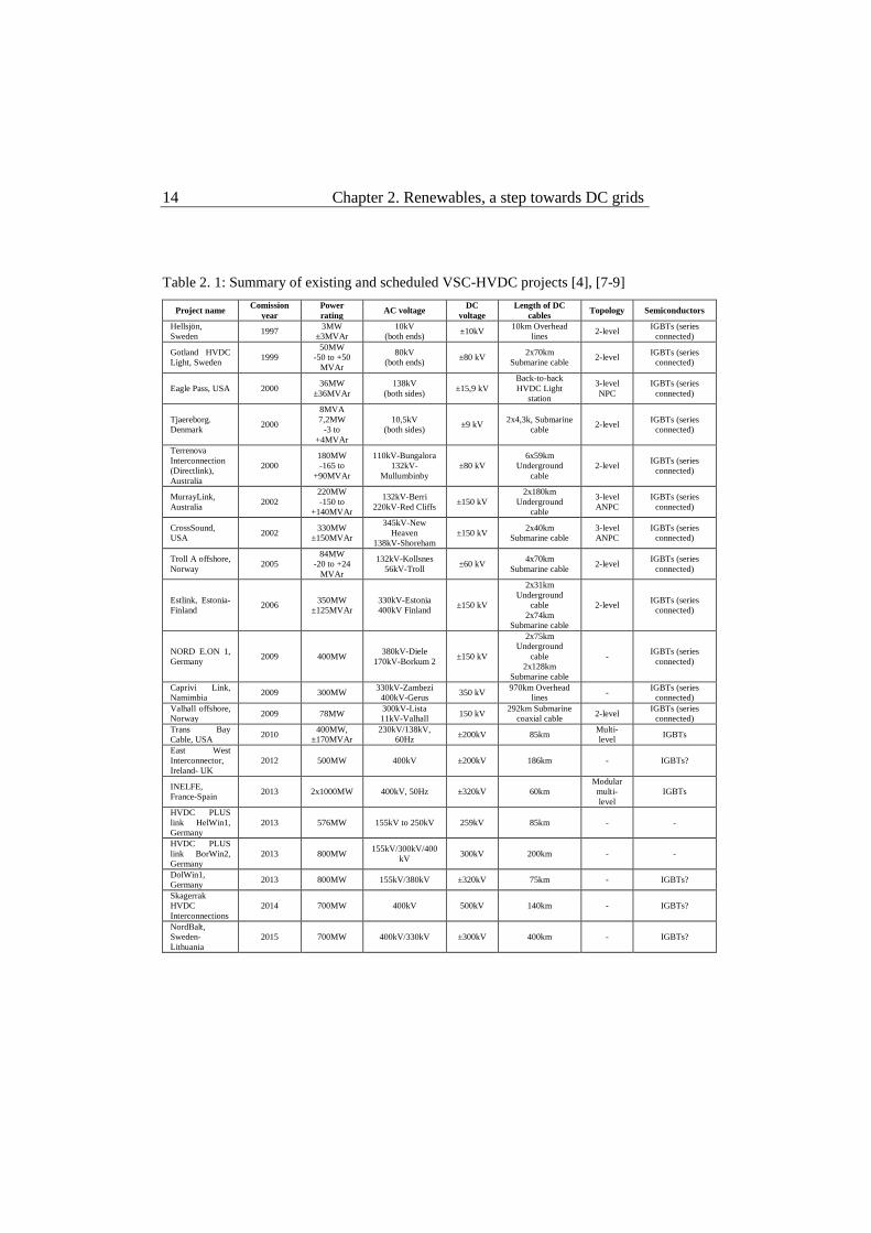
Table 2. 1: Summary of existing and scheduled VSC-HVDC projects [4], [7-9]
Project name Comission
year
Power
rating AC voltage
DC
voltage
Length of DC
cables Topology Semiconductors
Hellsjön,
Sweden 1997
3MW
±3MVAr
10kV
(both ends) ±10kV
10km Overhead
lines 2-level
IGBTs (series
connected)
Gotland HVDC
Light, Sweden 1999
50MW
-50 to +50
MVAr
80kV
(both ends) ±80 kV
2x70km
Submarine cable 2-level
IGBTs (series
connected)
Eagle Pass, USA 2000 36MW
±36MVAr
138kV
(both sides) ±15,9 kV
Back-to-back
HVDC Light
station
3-level
NPC
IGBTs (series
connected)
Tjaereborg.
Denmark 2000
8MVA
7,2MW
-3 to
+4MVAr
10,5kV
(both sides) ±9 kV
2x4,3k, Submarine
cable 2-level
IGBTs (series
connected)
Terrenova
Interconnection
(Directlink),
Australia
2000
180MW
-165 to
+90MVAr
110kV-Bungalora
132kV-
Mullumbinby
±80 kV
6x59km
Underground
cable
2-level IGBTs (series
connected)
MurrayLink,
Australia 2002
220MW
-150 to
+140MVAr
132kV-Berri
220kV-Red Cliffs ±150 kV
2x180km
Underground
cable
3-level
ANPC
IGBTs (series
connected)
CrossSound,
USA 2002
330MW
±150MVAr
345kV-New
Heaven
138kV-Shoreham
±150 kV 2x40km
Submarine cable
3-level
ANPC
IGBTs (series
connected)
Troll A offshore,
Norway 2005
84MW
-20 to +24
MVAr
132kV-Kollsnes
56kV-Troll ±60 kV
4x70km
Submarine cable 2-level
IGBTs (series
connected)
Estlink, Estonia-
Finland 2006
350MW
±125MVAr
330kV-Estonia
400kV Finland ±150 kV
2x31km
Underground
cable
2x74km
Submarine cable
2-level IGBTs (series
connected)
NORD E.ON 1,
Germany 2009 400MW
380kV-Diele
170kV-Borkum 2 ±150 kV
2x75km
Underground
cable
2x128km
Submarine cable
- IGBTs (series
connected)
Caprivi Link,
Namimbia 2009 300MW
330kV-Zambezi
400kV-Gerus 350 kV
970km Overhead
lines -
IGBTs (series
connected)
Valhall offshore,
Norway 2009 78MW
300kV-Lista
11kV-Valhall 150 kV
292km Submarine
coaxial cable 2-level
IGBTs (series
connected)
Trans Bay
Cable, USA 2010
400MW,
±170MVAr
230kV/138kV,
60Hz ±200kV 85km
Multi-
level IGBTs
East West
Interconnector,
Ireland- UK
2012 500MW 400kV ±200kV 186km - IGBTs?
INELFE,
France-Spain 2013 2x1000MW 400kV, 50Hz ±320kV 60km
Modular
multi-
level
IGBTs
HVDC PLUS
link HelWin1,
Germany
2013 576MW 155kV to 250kV 259kV 85km - -
HVDC PLUS
link BorWin2,
Germany
2013 800MW 155kV/300kV/400
kV 300kV 200km - -
DolWin1,
Germany 2013 800MW 155kV/380kV ±320kV 75km - IGBTs?
Skagerrak
HVDC
Interconnections
2014 700MW 400kV 500kV 140km - IGBTs?
NordBalt,
Sweden-
Lithuania
2015 700MW 400kV/330kV ±300kV 400km - IGBTs?
2.3. Visions and Challenges 15
Even though there is no practical experience of multi-terminal systems
using VSC-HVDC technology, VSC-HVDC technology has been used to
overcome CSC-HVDC technology disadvantages for point-to-point
connections of many different grids, including weak grids. The small
footprint of a VSC-HVDC substation makes its installation on offshore
platforms possible which greatly facilitates the integration of offshore
wind power plants.
The experience gained by the implementations mentioned in Table 2.1
showed that VSC-HVDC technology is able to provide power flow
flexibility, simpler control, independent active and reactive power control,
ability to connect any kind of system and black start capability [10]. All
these features are necessary for the formation of small, at first, and then
large multi-terminal HVDC systems that will greatly facilitate energy
trading among nations and integration of renewables.
2.3 Visions and Challenges
The potential of bulk energy transfer over long distances, that the HVDC
technology offered, triggered the interest of researchers for a highly
interconnected European-wide power system given the benefits of the
interconnected AC power system. As the deregulation of the electricity
market advanced and renewable power technology developed, taking an
important role in power production, different plans started appearing
regarding the future of the power system on a continental level [11]. The
deregulated market and the distributed production resulting by the use of
renewables require a flexible system that is able to transfer large amounts
of power across the continent if necessary. Making use of the HVDC
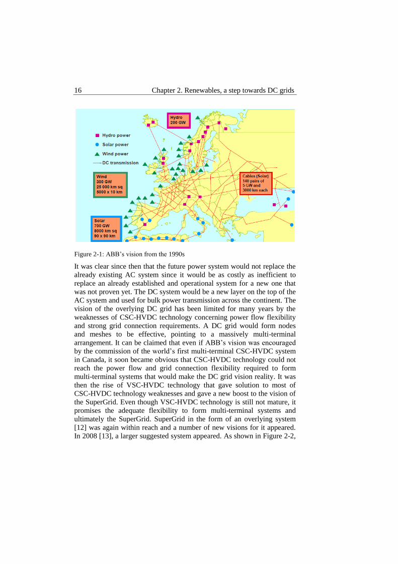
technology, ABB already in the 1990s presented its vision of the future
highly interconnected, European-wide power system shown in Figure 2-1.
In such system bulk power transmission was based on the HVDC
technology and much of its power production would be based on wind,
solar and hydro power dispersed around the continent.
16 Chapter 2. Renewables, a step towards DC grids
Figure 2-1: ABB’s vision from the 1990s
It was clear since then that the future power system would not replace the
already existing AC system since it would be as costly as inefficient to
replace an already established and operational system for a new one that
was not proven yet. The DC system would be a new layer on the top of the
AC system and used for bulk power transmission across the continent. The
vision of the overlying DC grid has been limited for many years by the
weaknesses of CSC-HVDC technology concerning power flow flexibility
and strong grid connection requirements. A DC grid would form nodes
and meshes to be effective, pointing to a massively multi-terminal
arrangement. It can be claimed that even if ABB’s vision was encouraged
by the commission of the world’s first multi-terminal CSC-HVDC system
in Canada, it soon became obvious that CSC-HVDC technology could not
reach the power flow and grid connection flexibility required to form
multi-terminal systems that would make the DC grid vision reality. It was
then the rise of VSC-HVDC technology that gave solution to most of
CSC-HVDC technology weaknesses and gave a new boost to the vision of
the SuperGrid. Even though VSC-HVDC technology is still not mature, it
promises the adequate flexibility to form multi-terminal systems and
ultimately the SuperGrid. SuperGrid in the form of an overlying system
[12] was again within reach and a number of new visions for it appeared.
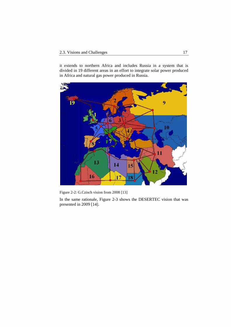
In 2008 [13], a larger suggested system appeared. As shown in Figure 2-2,
2.3. Visions and Challenges 17
it extends to northern Africa and includes Russia in a system that is
divided in 19 different areas in an effort to integrate solar power produced
in Africa and natural gas power produced in Russia.
Figure 2-2: G.Czisch vision from 2008 [13]
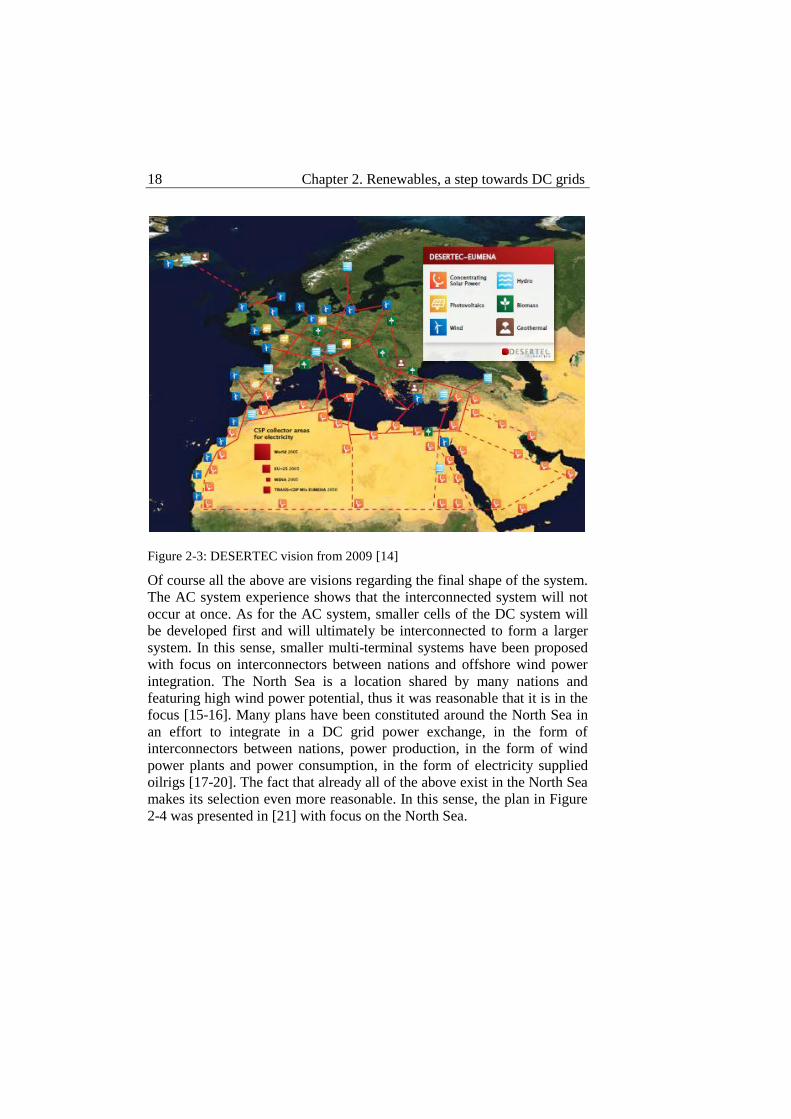
In the same rationale, Figure 2-3 shows the DESERTEC vision that was
presented in 2009 [14].
18 Chapter 2. Renewables, a step towards DC grids
Figure 2-3: DESERTEC vision from 2009 [14]
Of course all the above are visions regarding the final shape of the system.
The AC system experience shows that the interconnected system will not
occur at once. As for the AC system, smaller cells of the DC system will
be developed first and will ultimately be interconnected to form a larger
system. In this sense, smaller multi-terminal systems have been proposed
with focus on interconnectors between nations and offshore wind power
integration. The North Sea is a location shared by many nations and
featuring high wind power potential, thus it was reasonable that it is in the
focus [15-16]. Many plans have been constituted around the North Sea in
an effort to integrate in a DC grid power exchange, in the form of
interconnectors between nations, power production, in the form of wind
power plants and power consumption, in the form of electricity supplied
oilrigs [17-20]. The fact that already all of the above exist in the North Sea
makes its selection even more reasonable. In this sense, the plan in Figure
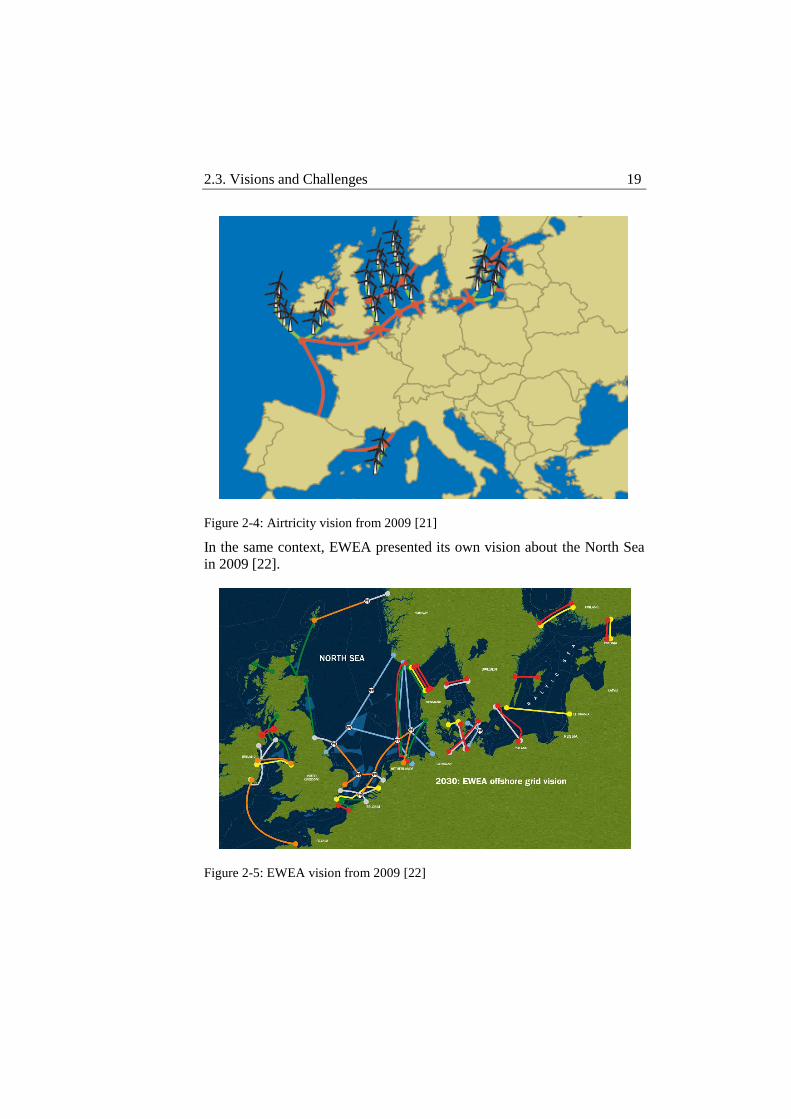
2-4 was presented in [21] with focus on the North Sea.
2.3. Visions and Challenges 19
Figure 2-4: Airtricity vision from 2009 [21]
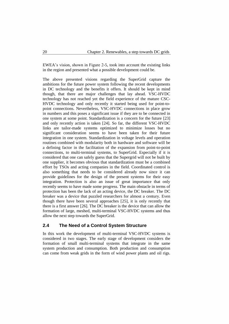
In the same context, EWEA presented its own vision about the North Sea
in 2009 [22].
Figure 2-5: EWEA vision from 2009 [22]
20 Chapter 2. Renewables, a step towards DC grids
EWEA’s vision, shown in Figure 2-5, took into account the existing links
in the region and presented what a possible development could be.
The above presented visions regarding the SuperGrid capture the
ambitions for the future power system following the recent developments
in DC technology and the benefits it offers. It should be kept in mind
though, that there are major challenges that lay ahead. VSC-HVDC
technology has not reached yet the field experience of the mature CSC-
HVDC technology and only recently it started being used for point-to-
point connections. Nevertheless, VSC-HVDC connections in place grow
in numbers and this poses a significant issue if they are to be connected in
one system at some point. Standardization is a concern for the future [23]
and only recently action is taken [24]. So far, the different VSC-HVDC
links are tailor-made systems optimized to minimize losses but no
significant consideration seems to have been taken for their future
integration in one system. Standardization in voltage levels and operation
routines combined with modularity both in hardware and software will be
a defining factor in the facilitation of the expansion from point-to-point
connections, to multi-terminal systems, to SuperGrid. Especially if it is
considered that one can safely guess that the Supergrid will not be built by
one supplier, it becomes obvious that standardization must be a combined
effort by TSOs and acting companies in the field. Coordinated control is
also something that needs to be considered already now since it can
provide guidelines for the design of the present systems for their easy
integration. Protection is also an issue of great importance that only
recently seems to have made some progress. The main obstacle in terms of
protection has been the lack of an acting device, the DC breaker. The DC
breaker was a device that puzzled researchers for almost a century. Even
though there have been several approaches [25], it is only recently that
there is a first answer [26]. The DC breaker is the device that can allow the
formation of large, meshed, multi-terminal VSC-HVDC systems and thus
allow the next step towards the SuperGrid.
2.4 The Need of a Control System Structure
In this work the development of multi-terminal VSC-HVDC systems is
considered in two stages. The early stage of development considers the
formation of small multi-terminal systems that integrate in the same
system production and consumption. Both production and consumption
can come from weak grids in the form of wind power plants and oil rigs.
2.4. The Need of a Control System Structure 21
In the early stage of development the multi-terminal system is radial and
no DC breakers are considered. In the latter stage of development, the
system becomes massively multi-terminal in a meshed arrangement where
DC breakers are indispensable. The focus is in offshore systems and this
division is made in accordance to the existing plans for offshore
development of wind power and multi-terminal HVDC systems in the
North and Baltic Sea.
The scope of this work is to investigate multi-terminal HVDC systems in
their early stage of development with the intention to make a contribution
in the development of a general control system structure that will be valid
at this stage of development of multi-terminal HVDC systems and outline
the control system structure of the latter stage of multi-terminal HVDC
development. Such a control system structure shall be highly oriented
towards modularity and expandability and thus, it shall be able to
accommodate different types of connected systems and equipment from
different suppliers. The ambition is to point out the main features that are
necessary for such a control system structure for reliable operation during
both normal and emergency conditions. The proposed control system is
then to be implemented and simulated on selected scenarios to verify its
efficiency. Possible improvements and future work is later discussed.
Chapter 3 System Operation and Control
There are certain analogies in the operation of an AC system and a DC
system from which useful information can be deducted for the operation of
a multi-terminal VSC-HVDC system.
In an AC system the indicator of power balance is frequency and for this
reason it is the focus of primary control to keep frequency between strict
margins. Changes in power influence the frequency of the system.
Whether they are caused by generation or load loss or because of the
scheduled, hourly power flow changes within the system, they create
deviations in the frequency of the system. This is because the kinetic
energy of the generators is used to balance the power changes in the
system; primary control is then responsible to balance the system at its
nominal frequency eliminating stationary errors.
Many generators operate in parallel in an AC system and each one of them
has different operating costs and rating limitations. Frequency droop is
used then to allow the different generators share the load. In combination
with an economic dispatcher, frequency droop can be manipulated to
impose load sharing to the different generators according to their operating
costs and rating limitations targeting in this way to an economic optimal
and yet safe operation of the system. The economic optimal operation in
the Scandinavian countries including Estonia and Lithuania is defined on
an hourly schedule that occurs from the day-ahead and intraday Nord Pool
spot markets.
In a DC system the indicator of power balance is the DC voltage. Even
though DC voltage will have different values at the different substations it
can be used as the power balance indicator. While a substation in a multi-
terminal VSC-HVDC system may operate in different control modes,
every control action is ultimately translated to changes in current that
3.1. Voltage Source Converter Principle of Control 23
directly affect the power balance and consequently the DC voltage. Since
there is no kinetic energy involved in this system the effect on the DC
voltage is immediate and thus its primary control has to be fast to keep the
DC voltage within strict limits. The DC system is expected to operate in
combination with the AC system, thus its power flows are scheduled on an
hourly basis as for the AC system. Power flow changes will then happen
every hour and the different substations will have to operate in parallel to
achieve them.
In the same manner as in the AC system, DC voltage droop control can be
used to make the different substations share load while collectively
supporting voltage regulation. In a multi-terminal VSC-HVDC system
different substations may have different ratings and different available
power at each point in time. This means that a dispatcher is necessary in a
higher control layer to play the role of secondary control and adjust
setpoints for DC voltage droop controllers in the system.
A substation in a multi-terminal VSC-HVDC system may have several
types of controllers apart from the DC voltage droop controller. This has to
do with the type of functionality that is necessary in the system and the
type of system each substation connects to the DC system. In any case, a
wide range of controllers at each substation provides a wider range of
control possibilities for the overall control system of the DC system.
To better understand today’s approach in the operation of multi-terminal
VSC-HVDC systems and their benefits and limitations, it is necessary to
take a step back and look at the principle of operation of such a system and
the development of its control. The heart of this system is its converter;
focusing on its characteristics and limitations as well as the operation of 2-
terminal systems, better understanding is reached regarding the operation
and requirements for a multi-terminal system.
3.1 Voltage Source Converter Principle of Control
The principle of operation of the three-phase VSCs used in HVDC systems
can be tracked down to the combination of simpler converter
arrangements. Switch mode converters are DC/DC power converters that
utilize fully controllable semiconductor switching devices to manipulate
the voltage level of the transmitted power. The most fundamental forms of
24 Chapter 3. System Operation and Control
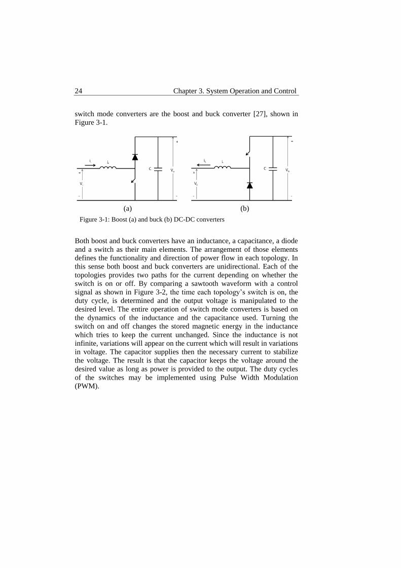
switch mode converters are the boost and buck converter [27], shown in
Figure 3-1.
Both boost and buck converters have an inductance, a capacitance, a diode
and a switch as their main elements. The arrangement of those elements
defines the functionality and direction of power flow in each topology. In
this sense both boost and buck converters are unidirectional. Each of the
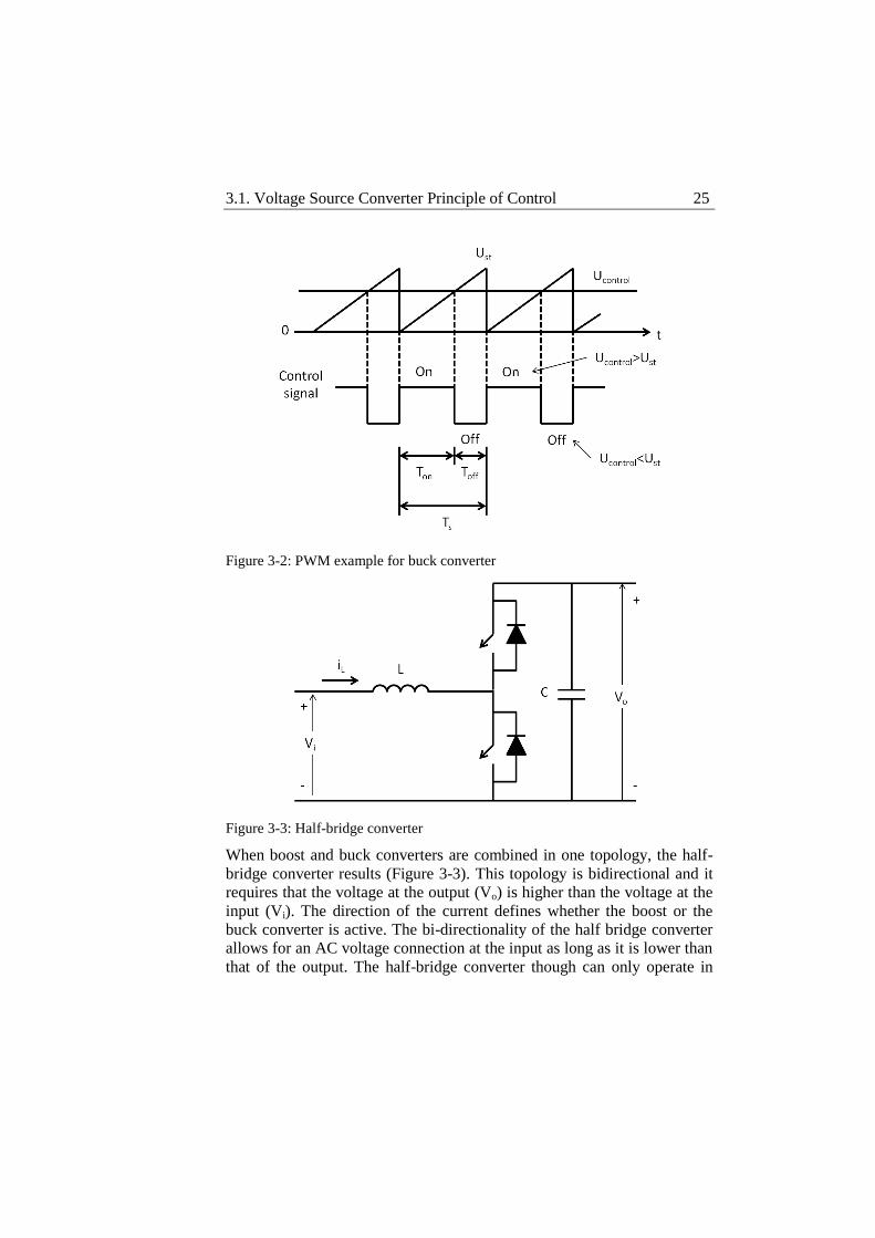
topologies provides two paths for the current depending on whether the
switch is on or off. By comparing a sawtooth waveform with a control
signal as shown in Figure 3-2, the time each topology’s switch is on, the
duty cycle, is determined and the output voltage is manipulated to the
desired level. The entire operation of switch mode converters is based on
the dynamics of the inductance and the capacitance used. Turning the
switch on and off changes the stored magnetic energy in the inductance
which tries to keep the current unchanged. Since the inductance is not
infinite, variations will appear on the current which will result in variations
in voltage. The capacitor supplies then the necessary current to stabilize
the voltage. The result is that the capacitor keeps the voltage around the
desired value as long as power is provided to the output. The duty cycles
of the switches may be implemented using Pulse Width Modulation
(PWM).
Figure 3-1: Boost (a) and buck (b) DC-DC converters
(a) (b)
3.1. Voltage Source Converter Principle of Control 25
Figure 3-2: PWM example for buck converter
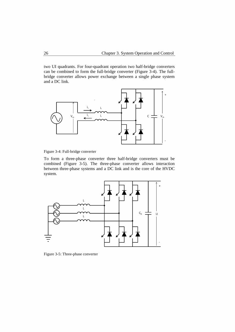
Figure 3-3: Half-bridge converter
When boost and buck converters are combined in one topology, the half-
bridge converter results (Figure 3-3). This topology is bidirectional and it
requires that the voltage at the output (Vo) is higher than the voltage at the
input (Vi). The direction of the current defines whether the boost or the
buck converter is active. The bi-directionality of the half bridge converter
allows for an AC voltage connection at the input as long as it is lower than
that of the output. The half-bridge converter though can only operate in
26 Chapter 3. System Operation and Control
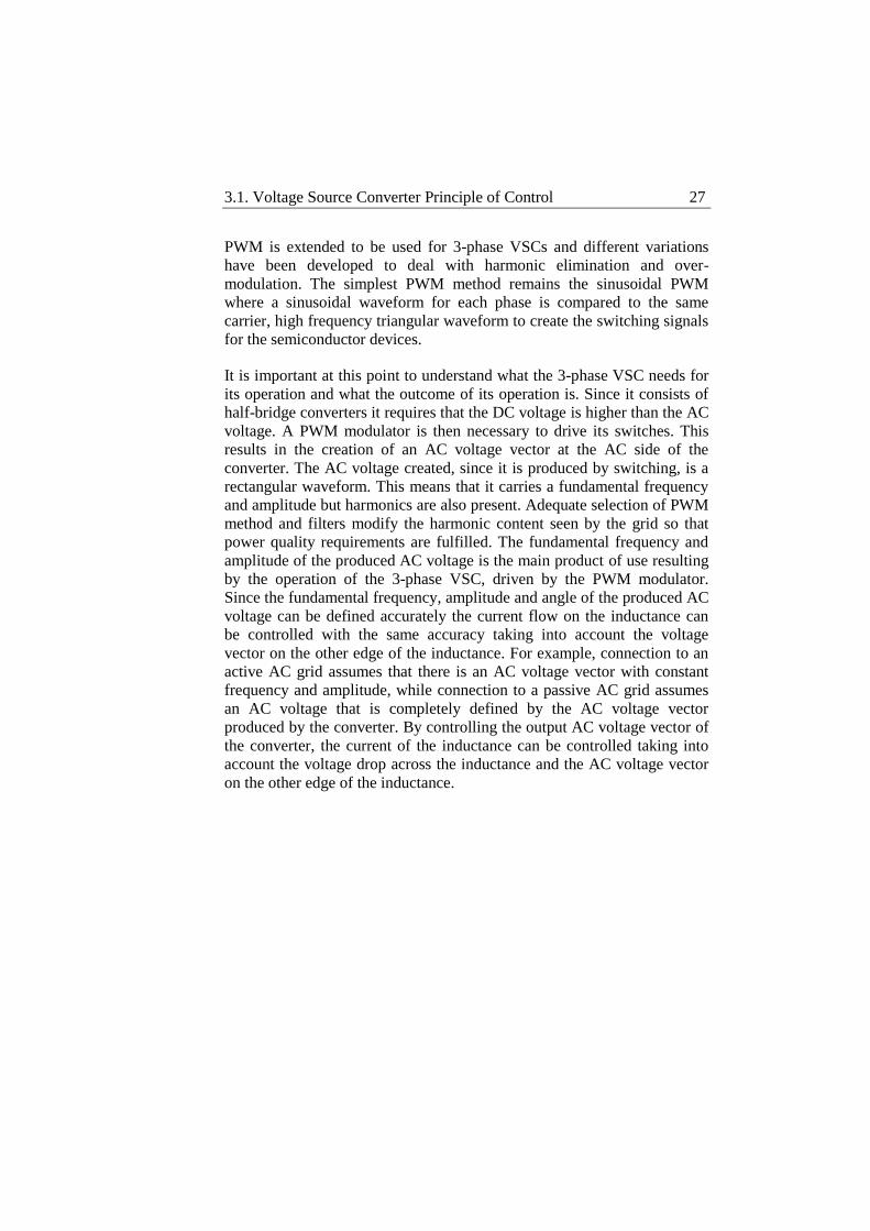
two UI quadrants. For four-quadrant operation two half-bridge converters
can be combined to form the full-bridge converter (Figure 3-4). The full-
bridge converter allows power exchange between a single phase system
and a DC link.
Figure 3-4: Full-bridge converter
To form a three-phase converter three half-bridge converters must be
combined (Figure 3-5). The three-phase converter allows interaction
between three-phase systems and a DC link and is the core of the HVDC
system.
Figure 3-5: Three-phase converter
3.1. Voltage Source Converter Principle of Control 27
PWM is extended to be used for 3-phase VSCs and different variations
have been developed to deal with harmonic elimination and over-
modulation. The simplest PWM method remains the sinusoidal PWM
where a sinusoidal waveform for each phase is compared to the same
carrier, high frequency triangular waveform to create the switching signals
for the semiconductor devices.
It is important at this point to understand what the 3-phase VSC needs for
its operation and what the outcome of its operation is. Since it consists of
half-bridge converters it requires that the DC voltage is higher than the AC
voltage. A PWM modulator is then necessary to drive its switches. This
results in the creation of an AC voltage vector at the AC side of the
converter. The AC voltage created, since it is produced by switching, is a
rectangular waveform. This means that it carries a fundamental frequency
and amplitude but harmonics are also present. Adequate selection of PWM
method and filters modify the harmonic content seen by the grid so that
power quality requirements are fulfilled. The fundamental frequency and
amplitude of the produced AC voltage is the main product of use resulting
by the operation of the 3-phase VSC, driven by the PWM modulator.
Since the fundamental frequency, amplitude and angle of the produced AC
voltage can be defined accurately the current flow on the inductance can
be controlled with the same accuracy taking into account the voltage
vector on the other edge of the inductance. For example, connection to an
active AC grid assumes that there is an AC voltage vector with constant
frequency and amplitude, while connection to a passive AC grid assumes
an AC voltage that is completely defined by the AC voltage vector
produced by the converter. By controlling the output AC voltage vector of
the converter, the current of the inductance can be controlled taking into
account the voltage drop across the inductance and the AC voltage vector
on the other edge of the inductance.
28 Chapter 3. System Operation and Control
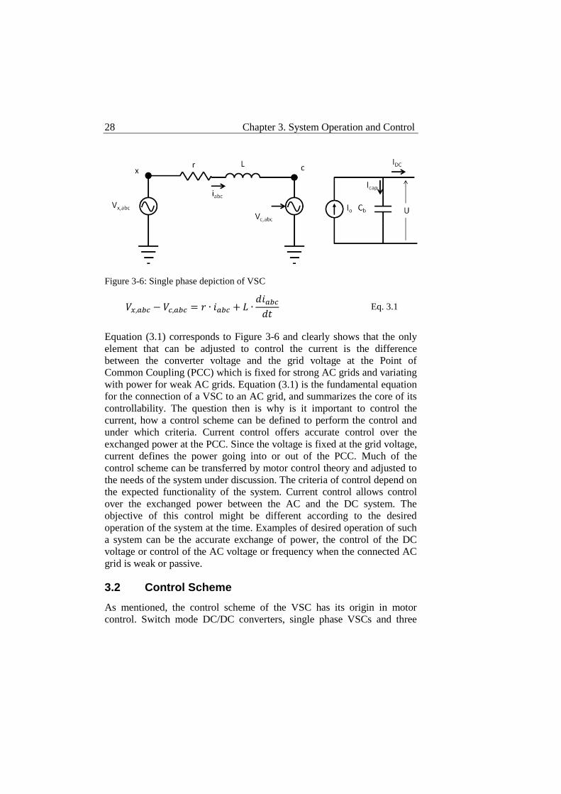
Figure 3-6: Single phase depiction of VSC
Equation (3.1) corresponds to Figure 3-6 and clearly shows that the only
element that can be adjusted to control the current is the difference
between the converter voltage and the grid voltage at the Point of
Common Coupling (PCC) which is fixed for strong AC grids and variating
with power for weak AC grids. Equation (3.1) is the fundamental equation
for the connection of a VSC to an AC grid, and summarizes the core of its
controllability. The question then is why is it important to control the
current, how a control scheme can be defined to perform the control and
under which criteria. Current control offers accurate control over the
exchanged power at the PCC. Since the voltage is fixed at the grid voltage,
current defines the power going into or out of the PCC. Much of the
control scheme can be transferred by motor control theory and adjusted to
the needs of the system under discussion. The criteria of control depend on
the expected functionality of the system. Current control allows control
over the exchanged power between the AC and the DC system. The
objective of this control might be different according to the desired
operation of the system at the time. Examples of desired operation of such
a system can be the accurate exchange of power, the control of the DC
voltage or control of the AC voltage or frequency when the connected AC
grid is weak or passive.
3.2 Control Scheme
As mentioned, the control scheme of the VSC has its origin in motor
control. Switch mode DC/DC converters, single phase VSCs and three
Eq. 3.1
3.2. Control Scheme 29
phase VSCs are attractive for motor control because they can manipulate
the terminal voltage of the motor, thus controlling its speed. Directly
controlling the input voltage alone of a motor is not the most efficient way
to control its speed though. Speed is sustained by controlling the torque of
the motor but torque is generated by the magnetic flux in the motor which
is, in turn, generated by the current through its windings. The VSC is then
called to provide the electrical power to be transformed into mechanical
power by manipulating the input voltage so that an adequate current flows
that will create the correct magnetic flux to produce the torque that will
sustain the speed of the motor at the desired level. A cascade control
structure is revealed in this sense, placing current control at the inner
control loop. The adequacy of the cascade control approach is supported
by the presence of different time constants in the system. While current
can change almost instantly, and torque follows the change in current, the
speed of the motor changes much more slowly due to the inertia of the
rotor. Cascade control allows the separation of the different time constants.
To simplify the control even further, since flux and voltage are rotating
vectors, the control is made not in the stationary abc frame but in the
rotating d-q frame. The controlled variables are then DC rather than AC
quantities, which makes control with no control error easier.
As in motor control, a grid connected VSC is responsible for the power
transfer between the AC system and the DC system. Thus, the control
structure can be directly transferred with the inner current control loop not
changing much [28], [29]. The outer control loop in the case of the motor
described above controlled the speed. In the grid connected VSC different
outer control loops might be present to control different variables, all of
which are translated to current references and through the inner current
control to voltage references for the PWM modulator. The d-q frame is
applicable in the grid connected VSC also since rotating voltage vectors
are to be manipulated.
Inner current control loop
The inner current control loop is based on a pair of P controllers to
separately control the active and reactive components of the current. It
receives current references from the outer control loops that converts to
voltage references for the PWM modulator. Since the control is made in
the d-q frame while the required voltage references are in the abc frame
30 Chapter 3. System Operation and Control
transformation is needed from the d-q frame to the abc frame, thus a phase
lock loop (PLL) is necessary to keep synchronization.
The control equation for the inner current controller is derived by equation
(3.1) and the power balance between the AC and the DC side of the
converter. Applying the Clark transformation [30] at equation (3.1),
[ ]
[
√
√
]
[
]
Equation (3.3) is obtained.
Before equation (3.1) is expressed in the d-q frame, Park’s transformation
must be applied.
}
Equation (3.1) is then expressed in the d-q frame in the following form.
( )
Which can be rewritten as:
Eq. 3.6
Eq. 3.5
Eq. 3.4
Eq. 3.3
Eq. 3.2
3.2. Control Scheme 31
Equation (3.6) can be rearranged in the following form,
}
Expressing the apparent power at PCC in the d-q frame, the following
expression is obtained.
( ) ( )
[( ) ( )]
At steady state operation, and neglecting any losses, active power on the
AC side is equal to the active power on the DC side.
( )
Full decoupling between the active and reactive current components can be
achieved by implementing the control in the d-q frame. The AC voltage
vector at PCC is placed on the d axis of the frame which rotates at its
rotational speed. Voltage at PCC can be expressed:
}
This makes the expression of active and reactive power as follows:
}
Eq. 3.11
Eq. 3.10
Eq. 3.9
Eq. 3.8
Eq. 3.7
32 Chapter 3. System Operation and Control
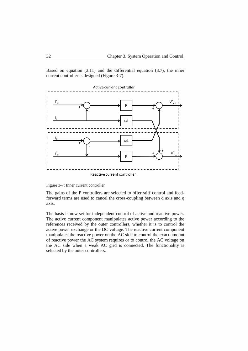
Based on equation (3.11) and the differential equation (3.7), the inner
current controller is designed (Figure 3-7).
Figure 3-7: Inner current controller
The gains of the P controllers are selected to offer stiff control and feed-
forward terms are used to cancel the cross-coupling between d axis and q
axis.
The basis is now set for independent control of active and reactive power.
The active current component manipulates active power according to the
references received by the outer controllers, whether it is to control the
active power exchange or the DC voltage. The reactive current component
manipulates the reactive power on the AC side to control the exact amount
of reactive power the AC system requires or to control the AC voltage on
the AC side when a weak AC grid is connected. The functionality is
selected by the outer controllers.
3.2. Control Scheme 33
Outer control loops
Different outer control loops can be used to provide references for the
active and reactive current. The outer controller set defines the control
mode set of the converter. Each outer controller controls a different
variable according to its control objective and translates it in current
reference. Since accuracy is required at this level PI controllers are used.
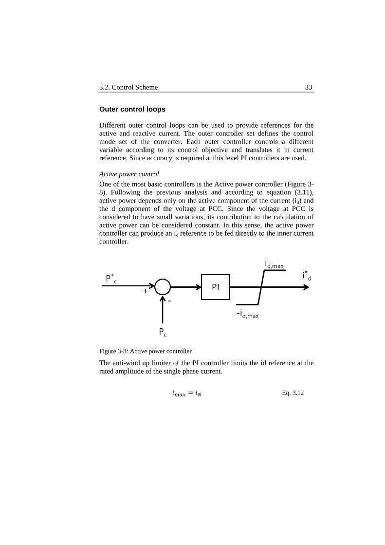
Active power control
One of the most basic controllers is the Active power controller (Figure 3-
8). Following the previous analysis and according to equation (3.11),
active power depends only on the active component of the current (id) and
the d component of the voltage at PCC. Since the voltage at PCC is
considered to have small variations, its contribution to the calculation of
active power can be considered constant. In this sense, the active power
controller can produce an id reference to be fed directly to the inner current
controller.
Figure 3-8: Active power controller
The anti-wind up limiter of the PI controller limits the id reference at the
rated amplitude of the single phase current.
Eq. 3.12
34 Chapter 3. System Operation and Control
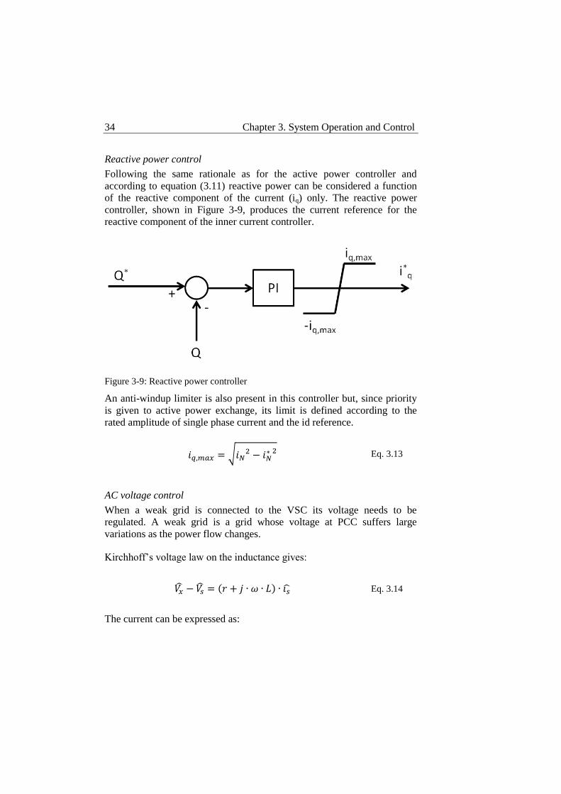
Reactive power control
Following the same rationale as for the active power controller and
according to equation (3.11) reactive power can be considered a function
of the reactive component of the current (iq) only. The reactive power
controller, shown in Figure 3-9, produces the current reference for the
reactive component of the inner current controller.
Figure 3-9: Reactive power controller
An anti-windup limiter is also present in this controller but, since priority
is given to active power exchange, its limit is defined according to the
rated amplitude of single phase current and the id reference.
√
AC voltage control
When a weak grid is connected to the VSC its voltage needs to be
regulated. A weak grid is a grid whose voltage at PCC suffers large
variations as the power flow changes.
Kirchhoff’s voltage law on the inductance gives:
( )
The current can be expressed as:
Eq. 3.14
Eq. 3.13
3.2. Control Scheme 35
(
)
(
)
(
)
And then the following expression can be obtained:
( )
( ) (
)
(
) (
)
Which, since the voltage variation at PCC on the imaginary axis is
negligible, gives:
(
)
In equation (3.17) the only available parameter to control is Q, since P is
already separately controlled. This can be expressed as follows.
The AC voltage controller is then an extension of the reactive power
controller and is presented in Figure 3-10.
Eq. 3.18
Eq. 3.17
Eq. 3.16
Eq. 3.15
36 Chapter 3. System Operation and Control
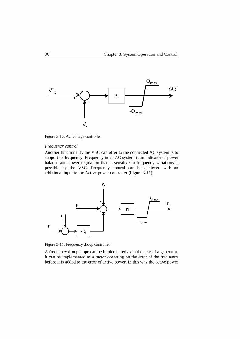
Figure 3-10: AC voltage controller
Frequency control
Another functionality the VSC can offer to the connected AC system is to
support its frequency. Frequency in an AC system is an indicator of power
balance and power regulation that is sensitive to frequency variations is
possible by the VSC. Frequency control can be achieved with an
additional input to the Active power controller (Figure 3-11).
Figure 3-11: Frequency droop controller
A frequency droop slope can be implemented as in the case of a generator.
It can be implemented as a factor operating on the error of the frequency
before it is added to the error of active power. In this way the active power
3.2. Control Scheme 37
reference becomes sensitive to frequency variations and its sensitivity can
be adjusted by adjusting the value of this factor. When the steady-state
error of the controller is zero, its input can be described by:
( ) (
)
This leads to power injection in the DC system by the VSC terminal that is
expressed by:
(
)
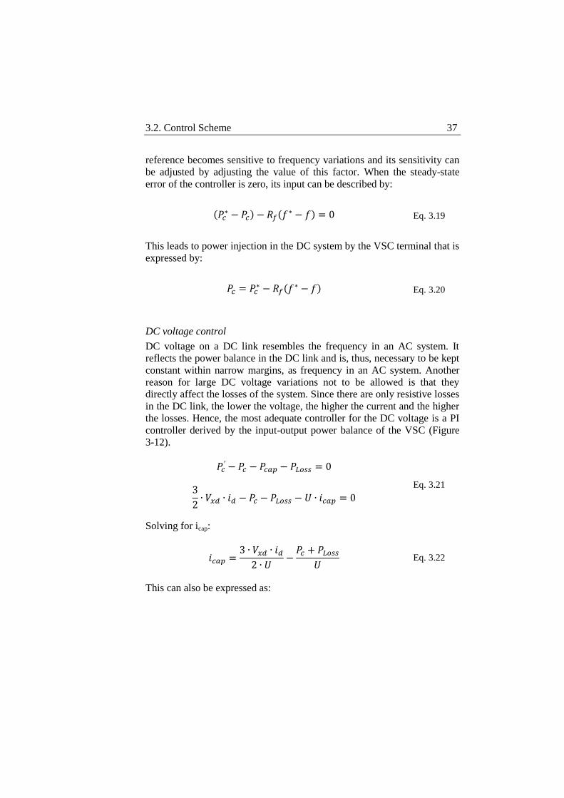
DC voltage control
DC voltage on a DC link resembles the frequency in an AC system. It
reflects the power balance in the DC link and is, thus, necessary to be kept
constant within narrow margins, as frequency in an AC system. Another
reason for large DC voltage variations not to be allowed is that they
directly affect the losses of the system. Since there are only resistive losses
in the DC link, the lower the voltage, the higher the current and the higher
the losses. Hence, the most adequate controller for the DC voltage is a PI
controller derived by the input-output power balance of the VSC (Figure
3-12).
Solving for icap:
This can also be expressed as:
Eq. 3.22
Eq. 3.21
Eq. 3.20
Eq. 3.19
38 Chapter 3. System Operation and Control
Combining equation (3.20) and equation (3.21) the following expression
occurs:
(
)
(
)
Equation (3.22) shows that the active component of the current (id) can be
used to regulate the DC voltage. Power losses can be compensated by
feed-forward, although the integral part of the controller will handle it
anyway.
Figure 3-12: DC voltage controller
DC voltage controller will maintain the DC voltage constant on the
reference value with as little variations as possible, as long the required
current is within the safe limits of the converter.
It should be mentioned at the end of this section that, in this work,
guidelines for controller tuning can be found in [31]. However, the final
tuning was made through trial and error.
Eq. 3.24
Eq. 3.23
3.3. System Operation 39
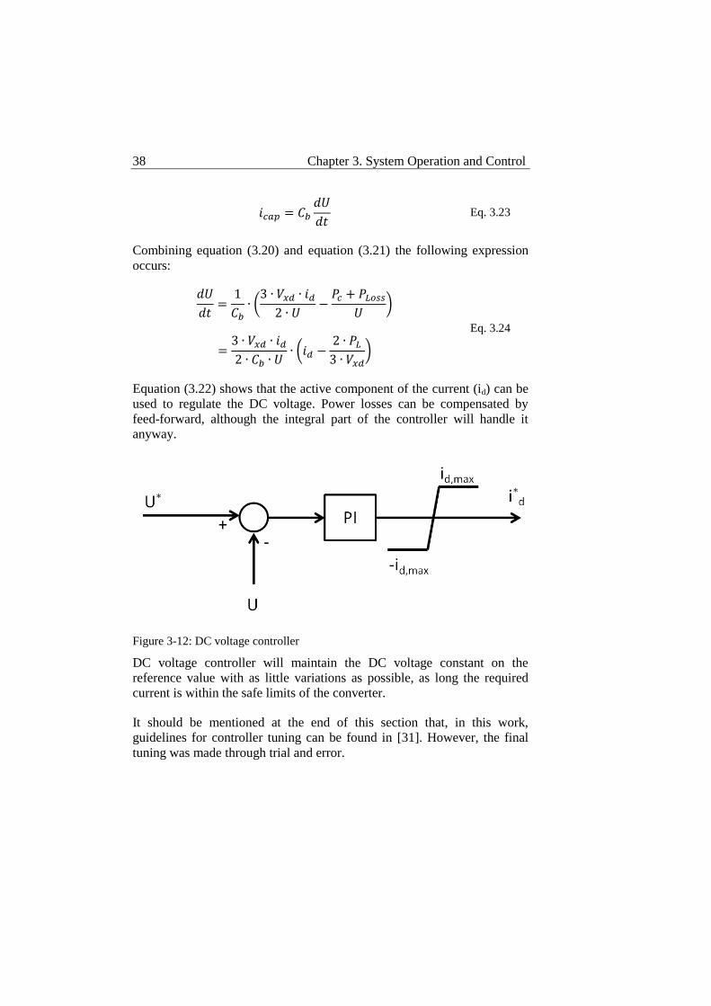
3.3 System Operation
Now that the main functionality of a VSC is explained, its operation will
be considered from a system perspective. The fundamental operation
targeted for VSCs is power transmission over long distances. The simplest
system configuration consists of two VSC terminals at the two edges of a
DC cable, together with any equipment required for filtering.
Two-terminal system
On a 2-terminal system, as in Figure 3-13, the power can be of fixed
direction or bi-directional, depending on the control modes implemented
on each terminal.
Figure 3-13: Two-terminal system
In the case that both VSC terminals are connected to strong grids, no
special functionality is required. One of the terminals functions as a
rectifier while the other functions as an inverter. The fundamental
condition for any power exchange over a DC link is that the DC voltage is
kept constant within strict limits. Thus, one of the terminals must control
the DC voltage using its DC voltage controller. The remaining terminal
can then operate at Active power control regulating the active power going
into or out of the DC link. The recommended operation is that the rectifier
operates at DC voltage control and the inverter at Active power control. In
this way the power flow is controlled by the inverter minimizing
overvoltage risks. If the inverter was to operate at DC voltage control and
the rectifier at Active power control, the operation of the link would still
be viable but a potential malfunction of the DC voltage controlling inverter
could lead to overvoltage since the rectifier would keep injecting power in
the DC link. Other combinations of control modes in the two terminals are
40 Chapter 3. System Operation and Control
the operation of both terminals at Active power control which is not viable
since the fundamental condition of a stable DC voltage is not assured, and
operation of both terminals at DC voltage control which is not viable since
no power setpoints can be implemented and a minor disturbance on the
DC voltage could lead the two competing DC voltage controllers to de-
stabilize the system.
If not both VSC terminals are connected to strong grids, they need to play
a different role implementing special control modes as long as one of them
controls the DC voltage. In the case of weak grid connection the AC
voltage must be supported or in the case of passive load connection
frequency needs to be supported by the VSC terminal. The most adequate
control mode combination needs then to be considered.
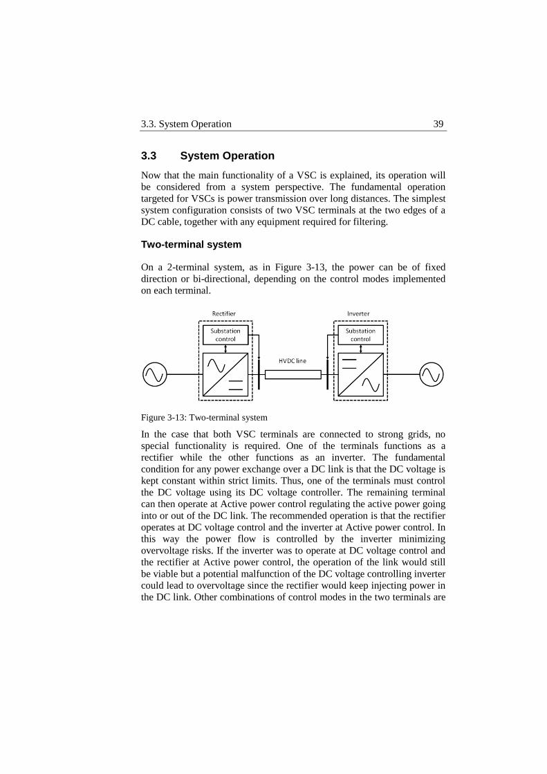
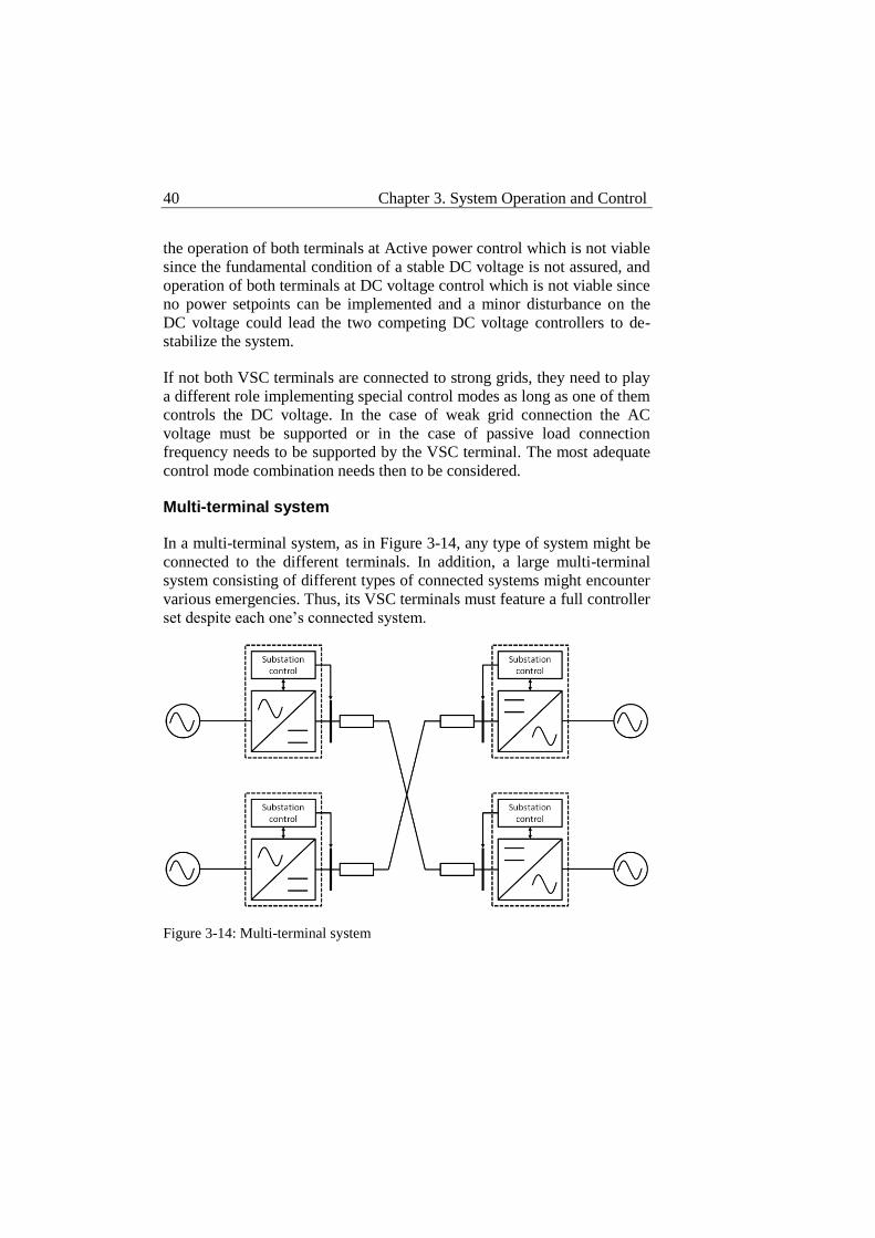
Multi-terminal system
In a multi-terminal system, as in Figure 3-14, any type of system might be
connected to the different terminals. In addition, a large multi-terminal
system consisting of different types of connected systems might encounter
various emergencies. Thus, its VSC terminals must feature a full controller
set despite each one’s connected system.
Figure 3-14: Multi-terminal system
3.3. System Operation 41
However, the main issue in a multi-terminal system is DC voltage control,
both in normal operation and during emergencies. DC voltage control
performed by one terminal in the multi-terminal system is an option,
deriving directly by the 2-terminal system operation. It is though, not a
desirable operation since it raises reliability issues at the event of DC
voltage regulating converter failure. Also, in normal operation the DC
voltage regulating converter (slack converter) is not able to share load
while operating other terminals in DC voltage control at the same time,
may lead to competing controllers, even when operated at different
setpoints, which may de-stabilize the system. Even in this case fast
communications are necessary to coordinate the setpoint distribution to the
different terminals. A coordinated approach is necessary to the control of
DC voltage in a multi-terminal system to avoid converter overloading,
controller competition and instability in case of slack converter failure.
Coordination of control modes and setpoints allows the control of the
power flow in a multi-terminal system in different ways.
Coordinated DC voltage control
Coordinated DC voltage control first addressed the issue of safety during
converter failure. As mentioned above, fast communications are necessary
to reassign DC voltage regulation to a new terminal in case of slack
converter failure. The voltage margin control method is designed to
address the reliability issues occurring by the regulation of the DC voltage
by a single slack converter in a multi-terminal system [19], [32]. To avoid
the uncertainty in the DC voltage regulation when the slack converter is
close to its capacity limits or when it suffers a failure and prevent
dependency on fast communications, the voltage margin control method
duplicates the slack converter functionality to other converters that can
take over the DC voltage control in a master-slave configuration. Master
converter operates in DC voltage control mode at the nominal DC voltage
and is designed to turn to Active power control mode when its capacity is
close to its limits. One of the slave converters, then, clamps the DC
voltage at another voltage level and follows the same behavior; when its
capacity is close to the limits it turns to Active power control and the next
slave converter takes over the voltage regulation. Different slave
converters are designed to clamp the voltage at higher and lower values in
a cascade manner that creates a safety margin for the DC voltage both for
higher and lower values from the nominal. Although the voltage margin
control method increases the overall reliability of the system several issues
42 Chapter 3. System Operation and Control
persist. There is still only one converter controlling the DC voltage at a
time which puts a lot of stress on it. The abrupt transition from one voltage
level to another puts extra stress on the system. To avoid voltage
regulation by more than one converters at a time the voltage margins of the
slave converters must be large enough which could lead to unwanted
oscillations and uncertain behavior of the system.
AC system operation offers some lessons to tackle these problems in the
operation of a DC system. In the AC system frequency is the indicator of
power balance. Frequency droop is used to coordinate the operation of the
different generators in the system making them sensitive to power changes
in the system. The slope of the frequency droop characteristic defines the
sensitivity of each generator and the load distribution among them.
Frequency is a universal characteristic within an AC control area, it is
something that the different generators throughout the control area sense
and react upon at the same time.
The equivalent magnitude in a DC system is the DC voltage. Although DC
voltage is the indicator of power balance in the DC system, the locally
measured DC voltage is not the same at all terminals. In this sense a DC
voltage-power sensitive controller can be designed for each terminal in the
system but different voltage setpoints are necessary for each terminal
taking into account voltage drops over the transmission line due to current
power flows, leaving the optimization to an overall control system. The
DC voltage-power sensitive controllers or DC droop controllers are able to
share load or power injection in the DC system while contributing
collectively in the DC voltage regulation and in this way participate in the
implementation of a control strategy for the system [33-37]. As shown in
Figure 3-15, the DC droop controller can be implemented as an additional
input to an active power controller with an adjusting factor operating on
the output of a P-controller. The adjusting factor is the equivalent of the
slope of the frequency droop characteristic and adjusts the sensitivity of
the active power controller at changes in the voltage.
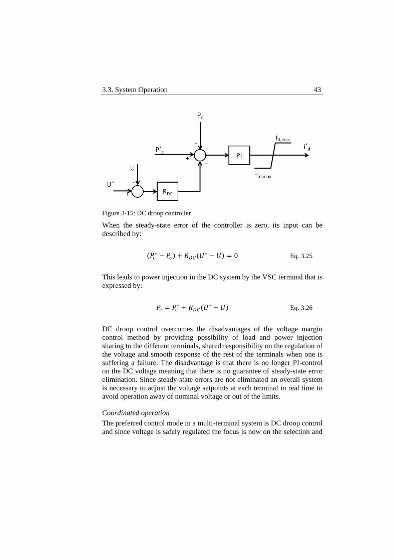
3.3. System Operation 43
Figure 3-15: DC droop controller
When the steady-state error of the controller is zero, its input can be
described by:
( ) (
)
This leads to power injection in the DC system by the VSC terminal that is
expressed by:
(
)
DC droop control overcomes the disadvantages of the voltage margin
control method by providing possibility of load and power injection
sharing to the different terminals, shared responsibility on the regulation of
the voltage and smooth response of the rest of the terminals when one is
suffering a failure. The disadvantage is that there is no longer PI-control
on the DC voltage meaning that there is no guarantee of steady-state error
elimination. Since steady-state errors are not eliminated an overall system
is necessary to adjust the voltage setpoints at each terminal in real time to
avoid operation away of nominal voltage or out of the limits.
Coordinated operation
The preferred control mode in a multi-terminal system is DC droop control
and since voltage is safely regulated the focus is now on the selection and
Eq. 3.26
Eq. 3.25
44 Chapter 3. System Operation and Control
implementation of adequate voltage and power setpoints for the different
terminals to keep the operation of the system as close as possible to the
nominal DC voltage. As mentioned above, this requires an additional
control level as depicted in Figure 3-16. An overall control system that has
the full picture of the system and takes into account the current power
flows in it. The overall control system must be in position to monitor the
different terminals before it is able to take action to coordinate them
distributing voltage and power setpoints to the different terminals in the
system. Monitoring and coordination require an interface for data
exchange between the overall system and the different terminals.
Functionality overlapping should also be avoided between the different
parts of the control system. For this reason a well-defined structure is
required to separate the entire control system including the overall control
system in different control levels with their respective domains of
responsibility. After having addressed the issue of reliable operation
during normal or abnormal conditions, the control system must also focus
on the expandability of the multi-terminal system. The structure of the
control system must be such that it enables the integration of new
terminals without major modifications. To achieve this, the interface
between the overall control system and the different terminals can play a
vital role. Standardization of the interface between the overall control
system and the different terminals can facilitate the implementation of the
logic of the control system in a way that allows easy integration of new
terminals.
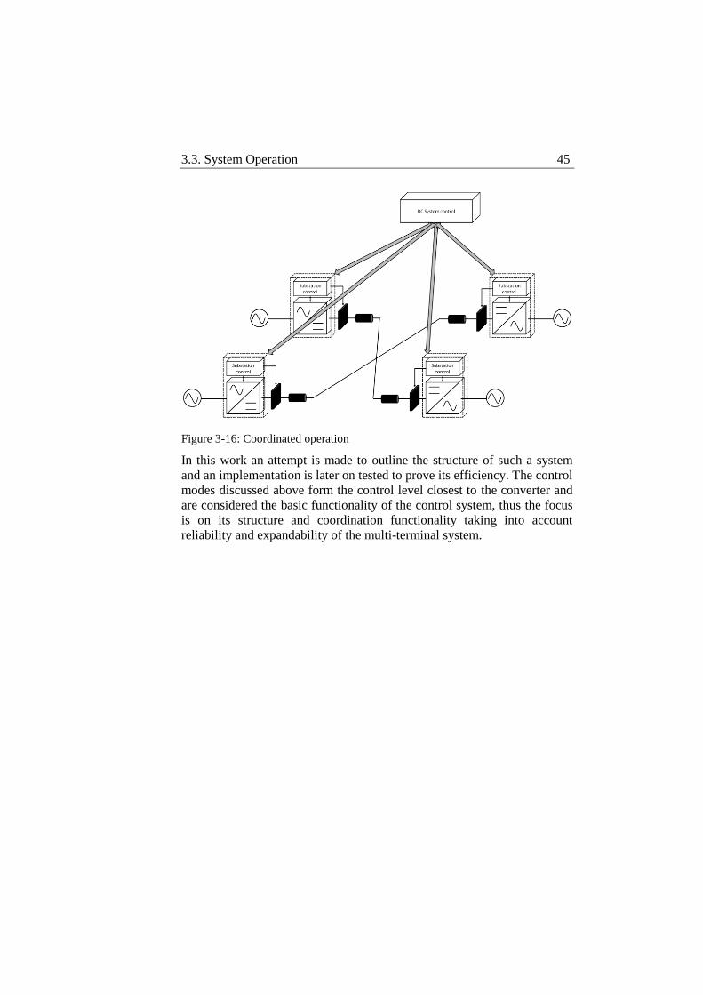
3.3. System Operation 45
Figure 3-16: Coordinated operation
In this work an attempt is made to outline the structure of such a system
and an implementation is later on tested to prove its efficiency. The control
modes discussed above form the control level closest to the converter and
are considered the basic functionality of the control system, thus the focus
is on its structure and coordination functionality taking into account
reliability and expandability of the multi-terminal system.
Chapter 4 Control System Structure
To achieve the coordinated function of the multi-terminal VSC-HVDC
system an overall control system is required. This could be an additional
layer to the already existing control system for 2-terminal systems. In this
case the overall control layer would have to adjust to the requirements of
the existing control system in each case, limiting in this way its future
expandability. An alternative is to reconsider the entire control system
establishing some necessary principles that it should comprise, both
structurally and operationally, to allow modularity in its structure and
facilitate its future expandability. If the control system is looked upon as a
whole, there is a range of functionalities it should support; from
operational tasks at its bottom layer to coordination tasks at its top layers.
These tasks can be performed by different control levels that can be
designed in accordance to the fundamental principles of the control system
not to obstruct modularity or expandability of the system. Well defined
responsibilities of each control level in combination with appropriate
interfacing can decouple the implementation of each control level from its
operation. In this way, automated functions that may be included in the
required functionality of each control level is independent of the
implementation approach as long as the required functionality is followed.
Since multi-terminal VSC-HVDC systems are expected to grow larger, it
is desirable that the control system accounts for this. The interconnection
of multi-terminal VSC-HVDC systems to form larger ones will create
common points among neighboring systems. The common points may be
shared substations and then control priority issues over the shared
substations may rise. A flat structure together with a priority system may
be the answer so it is desirable that the control system is flat structure
compatible by design.
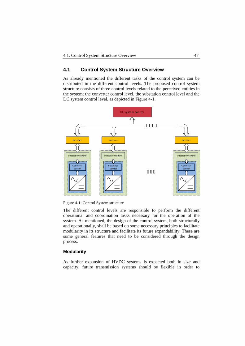
4.1. Control System Structure Overview 47
4.1 Control System Structure Overview
As already mentioned the different tasks of the control system can be
distributed in the different control levels. The proposed control system
structure consists of three control levels related to the perceived entities in
the system; the converter control level, the substation control level and the
DC system control level, as depicted in Figure 4-1.
Figure 4-1: Control System structure
The different control levels are responsible to perform the different
operational and coordination tasks necessary for the operation of the
system. As mentioned, the design of the control system, both structurally
and operationally, shall be based on some necessary principles to facilitate
modularity in its structure and facilitate its future expandability. These are
some general features that need to be considered through the design
process.
Modularity
As further expansion of HVDC systems is expected both in size and
capacity, future transmission systems should be flexible in order to
48 Chapter 4. Control System Structure
integrate more terminals both in numbers and diversity. This pushes the
expectations of such systems further than multi-terminal arrangements. It
is now required that these systems are also able to expand easily to
integrate diverse types of systems, from high capacity wind power plants
to oilrigs, without any major modification in their control system. Of
course a first step towards that direction is the standardization and
modularity of the hardware equipment to be used. Once the modularity of
hardware is established, the control system should have the appropriate
structure to integrate new terminals. For this reason it is necessary that
direct interaction between the individual terminals is avoided. This
interaction should only take place through the overall control system,
giving in this way the overall control system the flexibility to coordinate
terminals that have no “awareness” of the rest of the system. The
individual terminals will only be aware of their own local status and
safety, meaning that measurements will be obtained from both sides of the
terminal to achieve a certain objective that has been assigned to them by
the overall control system and also to keep their components within the
limits of safe operation. The individual terminals obtain in this way their
“distributed intelligence” that grants them with a certain degree of
autonomy, while at the same time the “brain” of the system, the overall
control, is released from operational duties and is left to deal with the
coordination of the different terminals. What is needed for the overall
control system to support such modularity is to minimize its input data.
This means that the overall control system will handle a minimum
necessary data set that will provide all the necessary information for the
coordination of the different terminals such as the number of the connected
terminals, the type of the connected systems, the instantaneous power
demand and offer of each of the terminals and a kind of prioritization
regarding importance, capacity and stiffness of the systems in case of
emergency. This assures that the system is coordinated to remain in a
stable operation under both normal and emergency conditions while at the
same time each individual connected system is operated according to its
properties. Having standard local controllers with a predefined range of
embedded control modes, the information of the type of the connected
system to the overall control system might exclude some operation modes
in order to secure stable operation. For example a passive connected
network cannot be assigned to support the DC voltage. The overall control
system will also deal with data regarding agreements between the involved
parts in order to formulate an operation strategy.
4.1. Control System Structure Overview 49
Uniform Interfacing
Since the substation is the common point between the multi-terminal
HVDC system and the connected system, the uniform interface aims to
decouple the different interfacing requirements of the different connected
systems with the multi-terminal HVDC system in two levels. First, since
the information of the type of the connected system is included in the
interface, the control mode set used by the connecting substation does not
have to be modified. The control system of the multi-terminal HVDC
system is able to exclude control modes in the respective substations
according to the properties of the connected system, enabling in this way
the use of a standard control mode set for all substations. Secondly, since
the information the substation itself exchanges with the overall control is
limited to a necessary minimum data set, the equipment supplier of the
substation is irrelevant as long as the exchanged data set is respected and
the expected functionality is followed.
In this way the transmission DC System Control can gather information by
all connected systems and schedule the coming power flows to satisfy
power demands and existing agreements between the involved parts.
Important information that the interface should also provide to the
transmission system is the information of the type of the connected
system. By introducing this information in the interface, the freedom of
operating individual systems by a standard interface is given. Instead of
adjusting the interface to the particular system, the system declares itself
as being of one type so that the transmission system knows how to operate
it. By having this information the transmission system excludes operation
modes or favor some of them in the expense of others choosing from a
range of operation modes of a standard terminal controller where all the
functionalities are defined. Information regarding capacity and stiffness of
each connected system will make possible for the transmission system to
prioritize accordingly systems of the same type in order to optimize
operation both under normal conditions and under emergencies.
Having this information the overall control system is in position to directly
intervene in the control of the substations when an emergency occurs or
simply supervise them during normal operation after having defined a
frame of operation for them regarding allowed control modes according to
the connected system.
50 Chapter 4. Control System Structure
Flat Structure Compatibility
As discussed earlier, further expansion of multi-terminal HVDC systems is
expected that may lead to the integration of regional multi-terminal VSC-
HVDC systems to a large DC grid. Since the DC grid will probably be
formed by the interconnection of the different individual early stage multi-
terminal HVDC systems, it is important to start considering already how
this integration can be facilitated on the control system level. The early
stage multi-terminal HVDC systems can be considered the “cells”, the
building blocks, from which the integrated DC system will occur. The
“cells” can be radial, in their most basic form, or meshed systems
depending on whether DC breakers are considered at the early stage of
development. In any case, the different “cells” define their own control
area that will later on be interconnected with others through shared
substations. The shared substation then needs to be bi-directionally
controllable since it will interface with two overall control systems of the
respective control areas. This raises the question of control priority among
the involved overall control systems. Technically, there should be no
priority, both overall control systems must have equal rights on the
operation of the shared substation and the substation itself must have the
freedom to select which overall system commands to follow only when its
safety is at risk. In this case, prioritization information in the interface of
the concerning shared substation can help implementing predefined
agreements between the involved parts for normal and emergency
operation and define the desirable hierarchy among the involved systems.
For this to be possible in the future, the control system for the early stage
multi-terminal HVDC systems must have this orientation and be designed
compatible with flat structure. Eliminating hierarchical structures in the
design of the control system will enable the implementation of hierarchy
among the different control areas of the integrated DC grid using the
prioritization in the shared substations according to the requirements of the
adjacent control areas. In one sentence the message is, instead of tailored
control system design to implement hierarchy among adjacent systems,
flat structure compatible control system design that allows prioritization to
tailor desirable hierarchies at request.
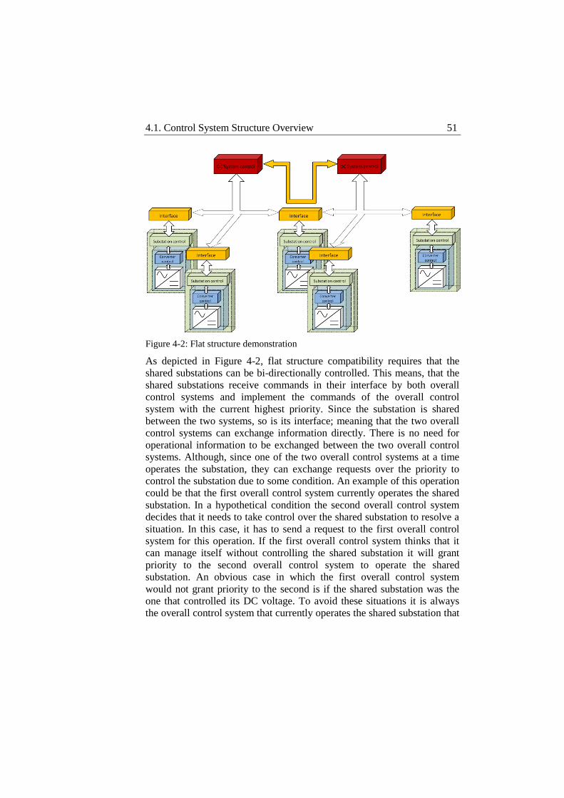
4.1. Control System Structure Overview 51
Figure 4-2: Flat structure demonstration
As depicted in Figure 4-2, flat structure compatibility requires that the
shared substations can be bi-directionally controlled. This means, that the
shared substations receive commands in their interface by both overall
control systems and implement the commands of the overall control
system with the current highest priority. Since the substation is shared
between the two systems, so is its interface; meaning that the two overall
control systems can exchange information directly. There is no need for
operational information to be exchanged between the two overall control
systems. Although, since one of the two overall control systems at a time
operates the substation, they can exchange requests over the priority to
control the substation due to some condition. An example of this operation
could be that the first overall control system currently operates the shared
substation. In a hypothetical condition the second overall control system
decides that it needs to take control over the shared substation to resolve a
situation. In this case, it has to send a request to the first overall control
system for this operation. If the first overall control system thinks that it
can manage itself without controlling the shared substation it will grant
priority to the second overall control system to operate the shared
substation. An obvious case in which the first overall control system
would not grant priority to the second is if the shared substation was the
one that controlled its DC voltage. To avoid these situations it is always
the overall control system that currently operates the shared substation that
52 Chapter 4. Control System Structure
decides whether to grant priority to another system over the shared
substation and it is not possible that an overall control system arbitrarily
assumes control over a shared substation at any time and without previous
consultation.
Automated Functions
Unlike scheduled power flows that are scheduled in advance according to
an operation strategy following existing agreements and predicted power
demands, emergency situations happen randomly and have to be dealt with
very quickly. A multi-terminal VSC-HVDC system has the ability of
rearranging its power flows very quickly but modularity dictates no
interaction between individual terminals and large disturbances cannot be
handled locally, they have to be handled by the overall control system.
Local terminal controllers will try to protect their own components in this
kind of situation which will reach their limits unless a change in the total
power flow in the DC system is done in an effort to stabilize the system.
The overall control system is then supposed to take action in order to
rearrange the power flows in the system to regain stability. One important
condition is the fast detection of a disturbance whether it is internal or
external to the HVDC system. And then the coming issue is what the time
span available to take action is. This time span is significantly reduced
when the discussion is about interconnected nations where a disturbance
could propagate to disturb the operation of neighboring national grids. It
becomes obvious that human operators, although they are efficient in
scheduling power flows ahead, could not handle an emergency in that
short time span. Disturbances could though be handled by automated
functions embedded in the overall control system of the transmission
system. The combination of automated functions operating under
predefined conditions with the fast controllability of a VSC-HVDC system
could give an almost immediate, yet controlled, response upon the
detection of a disturbance. Important issues that rise are how automated
functions can become general to fit the modularity of the system and how
much system resources should be deducted to support the stability of an
external system not to affect the others.
Regarding the first issue, in order for the automated functions to be as
general as possible, they should be activated and function according to
specific events that might happen in any terminal after the detection of a
4.1. Control System Structure Overview 53
disturbance. There should not be any emergency scenario involving
specific terminals. After the detection of a disturbance, automated
functions should be activated to coordinate terminals with specific
characteristics, regarding type, capacity and current status that can be
found in the information obtained by the overall control system through
the uniform interfaces. The concept is to divide disturbances into smaller
scale events that will trigger different automated functions to provide step-
wise adjustable approach to any disturbance. So instead of giving an
overall response to a major disturbance that is limited to predefined
scenarios, the aim is to provide automated functions that will attack a
disturbance step by step so that it is possible to reconsider the status of the
system after every step and rearrange strategy if needed.
Regarding the second issue of how much system resources should be
deducted to support the stability of an external system; this should be part
of the agreement between the involved parts. Each part should agree
beforehand how much and what kind of support should be expected in
case of emergency. The quality and quantity of the services for each part
should be included in the partners’ agreements.
Coordination Functions
The coordination of the different terminals in the system is the most
important responsibility of the system. Since the safe operation of each
terminal is managed in the Substation and Converter Control levels,
coordination is left for the DC System Control level. Substation and
Converter Control levels must be restricted to their local authority to
sustain the modularity of the system. Then, DC System Control level that
receives information from all the terminals is the most adequate to
coordinate them to operate as a system.
Coordination is performed by different coordination functions that are
spread in the different stages of system operation. The basic coordination
functions can be classified as:
Start up function
Schedule management function
54 Chapter 4. Control System Structure
Emergency function
Coordination action is necessary in all stages of the operation of system,
although it may differ according to the desired result. The startup stage of
the system operation is a preparation stage. The system needs to energize
the DC link before any power exchange is possible. Having multiple
terminals connecting various systems, means that startup needs to be a
coordinated procedure. In multi-terminal VSC-HVDC system the
connected AC system might range from strong national grids, to weak
grids such as WPPs and passive loads such as oilrigs. To initiate the
startup procedure, the Control System needs to first identify the connected
AC systems, and then decide which of them will be used to charge the DC
link. The Control System will involve all available active grids in the
process stressing them according to their capability unless otherwise
defined in agreements between the involved parts. Coordination action at
this stage involves selection of the terminals to be utilized and distribution
of the respective voltage setpoints.
When the DC link is charged the system is ready to perform the scheduled
power flows. Coordination for the DC System Control level in this stage
consists in managing the schedule delivered to it. The schedule holds
information regarding control modes and voltage and power levels for the
different terminals to define the requested power flows in the system. DC
System Control level manages the timing of the implemented power flows
and divides the schedule in parts according to the concerning terminal in
the system in order to distribute those parts of the schedule to the
respective terminals. As a preventive measure, DC System Control
distributes to the different terminals in the system schedule ahead of time
to anticipate potential communication loss events. At the same time DC
System Control receives feedback by the terminals regarding their
operation status. This is to validate the implementation of the requested
power flows and intervene in case of fault.
When a fault happens, in this case an AC 3-phase fault is considered, the
terminal that suffers it acts to protect its equipment. This makes the
terminal inaccessible for the DC System Control. Nevertheless, DC
System Control is informed about the fault and is called to take action to
reschedule the power flow in the system. Rescheduling might happen
according to different criteria, for example power demand matching. DC
4.2. Control Levels 55
System Control will first identify the power flow in the system before the
fault and then try to match the remaining power demand in the system. If
the remaining power production in the system is enough to match the
power demand, DC System Control will distribute new power setpoints to
the remaining terminals to match it. In case the power demand is higher
than the available power production, the power setpoints are calculated so
that maximum power is provided to the consuming terminals in an effort
to support demand in the best possible way. In the case of the AC 3-phase
fault, the local preventive action of the Substation Control level to prevent
equipment damage is followed by the corrective coordination action of the
DC System Control level to reschedule the power flows in the system to
limit the propagation of the disturbance to the adjacent systems.
Having these basic principles in mind the control levels can be defined
together with their responsibilities.
4.2 Control Levels
The functionalities of the control system are distributed in its different
levels and range from terminal coordination and substation safety to
converter control. If expandability is the target, modularity is the tool. To
achieve modularity the control system focuses on explicitly defining the
responsibilities of each control level and the interfaces between each other.
In this way each control level has a very specific domain of responsibility
and through uniform interfacing it is made possible that the actual
implementation of each control level is not relevant to the operation of the
control system as long as it responds to its duties and exchanges the
necessary data as defined by the interface. In practice, this means that
different suppliers of hardware or software equipment can operate under
the same roof as long as they comply with this minimum interface data and
functionality set.
This can prove quite useful in a field with no standardization at present.
Even if standardization was in place, one can safely guess that not all
multi-terminal VSC-HVDC systems will be built by the same supplier.
The case will most likely be that even for the same system, equipment will
come from different suppliers. Then a control system structure is necessary
to accommodate the different approaches in the substation control of the
different suppliers and achieve their coordinated operation.
56 Chapter 4. Control System Structure
In an effort to systematically classify the different system functionalities in
distinct responsibility domains, the proposed control system is structured
in three levels, as shown in Figure 4-1:
DC System Control level
Substation Control level
Converter Control level
This fundamental hierarchical structure represents a top-to-bottom
classification of the control levels included in the control system. The
lower a control level is in the hierarchy the narrower is its responsibility
domain. In principle, each control level follows the commands received by
its superior but this holds as long as each level’s safety is not breached. In
other words, each control level must follow the received commands but
has the freedom to decide for itself and act to protect the equipment that is
responsible for when it comes to security margins and then inform its
superior. This is possible due to the bi-directional data flow and
handshaking operations between the different control levels.
It is important to mention at this point that an important feature of the
proposed control system does not appear in the above classification since it
is functionality is not to process or produce data for any other control
level. The uniform interface is responsible for performing the data transfer
between DC System Control level and Substation Control level in a
uniform and modular way. It does not appear in the classification above
since it is not another control level but it will be described in this section
since it is a defining feature of the proposed control system and as
important as the system structure itself.
DC System Control level
DC System Control level plays the role of the supervisory control of the
system. It gathers information from the entire system through the uniform
interfaces to coordinate the different terminals to perform the necessary
actions. It receives the schedule to be implemented, distributes it to the
different substations and constantly monitors the system for fault signals
that require its intervention. Automated functions allow DC System
4.2. Control Levels 57
Control to quickly intervene when necessary and perform emergency
power flow rescheduling. General search functions allow it to address the
different terminals within its domain of responsibility according to their
characteristics, without using any predefined naming. This makes the
integration of new terminals easy since no modification in the control
system is required to include them in the control procedures.
The operation of DC System Control is divided in different stages through
which it proceeds according to the feedback it receives by the Substation
Control level. During initialization DC System Control recognizes the
system. The assumed topology is radial at this first stage of development
and DC System Control reads how many terminals are connected to the
system. After an error check DC System Control sets the error-free
terminals ready for operation. From the ready to operate terminals a
selection of one terminal or a group of terminals is made to charge the DC
system. The selected terminals are then commanded to charge the DC link
and DC System Control waits for feedback regarding the DC link voltage.
When the DC link is charged to the right level, DC System Control moves
into normal operation.
In normal operation DC System Control receives the required power flow
schedule as an input and distributes it to the different substations. It is
important to note at this point the difference in the operation of DC System
Control in comparison to prior-to-normal operation. Before the normal
operation stage DC System Control delivers commands and setpoints
directly to the different substations (Operational management) while
during the normal operation stage DC System Control delivers the
schedule to the different substations instead (Schedule management).
Operational management is used in general for out-of-normal operation
whether this has to do with the preparation of the system for normal
operation or with the operation of the system under disturbances.
Operational management assumes proper function of communications and
it is preferred because it can readjust setpoints dynamically to influence
the power flows in the system under close supervision. Schedule
management on the other hand is used during the normal operation of the
system. It assumes that the system operates far from extremities and
substations are given the freedom to take care of themselves following the
given schedule. This makes the system immune to communication loss
events for a time interval that can be defined according to the requirements
58 Chapter 4. Control System Structure
of the system. Even in this case, DC System Control retains its supervisory
role and Operational management will override Schedule management
upon a perceived emergency.
A severe disturbance in the AC side can shut down the respective
substation. When this happens a power imbalance is instantly created in
the DC system. During such disturbance, DC System Control assumes the
direct control of the terminals and imposes Operational management over
Schedule management. DC System Control must then act as quickly as
possible to limit the consequences of the disturbance, firstly in the DC
system and secondly their expansion to adjacent AC systems. Since DC
System Control directly operates on the remaining substations the actions
it can take range from appropriate control mode selection to power flow
rescheduling which can take place according to predefined criteria. It is
important to mention at this point that DC System Control loses control
over the faulted substation in the sense that the substation itself prioritizes
its own decisions to protect itself. The only way for the faulted substation
to return under the control of DC System Control is that the fault to which
it responded is removed or DC System Control creates power flows that do
not violate the faulted substation’s safety margins using the remaining
substations.
In all, DC System Control can be a gentle supervisor or an aggressive
guard of the system’s operation. It will try to create the necessary
conditions for the different substations to operate as independently as
possible and to protect them from possible mishaps but it will intervene
aggressively in their operation when the system’s operation is in jeopardy.
Its access to data from all substations of the system allows it to have a
complete image of the system at all times, and its direct access to the
controls of each substation gives it the chance to directly affect this image
of the system when necessary.
Substation Control level
The Substation Control level consists of all the Substation Control Objects
(SCOs) that correspond to the different terminals. Each SCO receives its
individual identity by which it is known to the DC System Control level
and is responsible for the safe operation of the terminal it operates. The
SCOs receive direct commands or schedule commands by the DC System
4.2. Control Levels 59
Control level through the uniform interface. The commands are interpreted
and arranged in a way the lower control level of Converter Control can
recognize. The SCOs also receive data in the form of measurements from
the Converter Control level that they use for their operation. A selection of
this data is also placed in the uniform interface to be forwarded to the DC
System Control level. The SCOs can be directly operated for out-of-
normal operation or operate independently according to the schedule they
receive by their DC System Control level. In any case, the first priority of
any SCO is to protect the substation equipment, for this reason in case of
safety margins breach the SCO will circumvent any control request in an
effort to protect the respective equipment. When this happens an error
signal is sent to DC System Control level so that the DC System Control
level does not expect the specific SCO to follow any requested command.
This may lead to the need for emergency rescheduling by the DC System
Control level which will force the rest of the SCOs to accept direct control
to balance the system.
The SCOs are expected to interface in a common way with the DC System
Control level for which the uniform interface is responsible. For this to
have any meaning, the SCOs must support a range of control modes
regardless of the way they actually implement them and have the expected
effect on the physical system when these control modes are used. The
range of the supported control modes can be wider than the range of the
control modes that each of the adjacent AC systems can support. In this
case the information of the type of the connected AC system in the
uniform interface will allow the DC System Control to exclude a part of
the control mode range for specific terminals. For example, a terminal
connecting a passive load cannot be operated at DC voltage control but in
no case can the DC voltage control mode be totally excluded by the
control mode set of the control system.
The control of the converter is decoupled in the d-q frame. The SCOs do
not handle the control of the converter directly, but they have to provide
the next control level with the right signals to do it. The SCOs are
responsible for interpreting the control requests they receive, in separate
control signals for the d and q axis. The control modes supported or at
least requested by the SCOs have to be present in the next control level as
well. The SCOs then, according to the requested control mode creates the
respective control signals that activate the right set of controllers in the
60 Chapter 4. Control System Structure
next control level and provide them with the right setpoints for their
operation. The suggested control mode set in this work contains:
DC droop voltage control
DC voltage control
Active power control
Reactive power control
AC voltage control
The control mode set up can of course be wider, but these control modes
are considered adequate at this point of this work.
For the sake of modularity, the different SCOs in a system are not allowed
to interact directly. If direct communications were to be established
between the different SCOs, the integration of new terminals would turn a
complicated task. For data to be exchanged between specific substations,
their individual interfacing needs should be matched leading to special
interfaces for each of this type of communication connection. This means
that for any new terminal addition all these communication connections
would have to be reconsidered. The data exchange and their paths would
also become complicated and detecting a communication failure would be
cumbersome, let alone handling it. For all the above reasons the proposed
control system structure does not allow the individual terminal SCOs to
communicate with each other, interfacing is allowed with DC System
Control level only that is the sole responsible for the coordination of
system operation.
Converter Control level
The Converter Control level is the lower control level and the closest to
the converter in this control system structure. It consists of the different
Converter Control Objects (CCOs) that correspond to the different
terminals in the system. Each CCO contains the necessary controller set
for its converter to perform the expected operation of the terminal
according to the type of AC system it connects to the DC system. All
4.2. Control Levels 61
measurements that are gathered by the physical system and end up to DC
System Control level through the Substation Control level are first
collected in Converter Control level. This happens because it is in the
Converter Control level that the continuous control of the converter takes
place. The different P and PI controllers forming the controller set of the
different CCOs need real measurements to operate apart from the setpoints
received by the Substation Control level. Also fast current changing faults
in the AC side need to be dealt with as soon as possible when they happen
and intervention is not needed by any higher control level since the first
priority again here is to preserve component safety.
The standard CCO contains an inner current control loop which receives
its setpoints by a set of outer control loop controllers, as shown in Figure
4-2. While the inner current control loop is indispensable in this kind of
implementation, the controllers of the outer control loop can vary to match
the expected functionality of each terminal. As mentioned in Substation
Control level section the suggested outer loop controller set in this work
contains a DC droop voltage controller, a DC voltage controller, an Active
power controller, a Reactive power controller and an AC voltage
controller. Although it would be possible to have different controller sets
for the different terminals, the controller sets of all terminals are selected
to be identical in this work. Not all controllers are used in all terminals and
for this a controller that is not used gets disabled saving simulation time
since no integrator operates on any uncontrolled variable.
Converter Control level is the most dependent control level of the three
since it needs a continuous supply of control commands and setpoints. It
communicates only with its directly superior control level, the Substation
Control level, and if its communications fail it keeps implementing the last
received control request. Although, communication failure at this level is
not considered a real threat since both the SCO and the CCO will be
accommodated in the substation and will not be exposed to the possibly
harsh environmental conditions. The only freedom of self-management
the CCO has is during faults on the AC side. It is considered that in this
case if the CCO was to follow the requested operation safety margins
would be breached leading to equipment damage taking down the
substation for a long period of time. Instead, CCO detects high currents
and responds according to the type of the detected AC fault circumventing
any control requests from higher control levels.

62 Chapter 4. Control System Structure
Figure 4-3: Controller configuration
Uniform Interface
As mentioned earlier the uniform interface is not yet another control level,
it is considered though a defining feature of the proposed control system
structure and thus its functionality will be described in this section. The
uniform interface is the means of communication between the different
SCOs and the DC System Control level. It establishes a common pattern
for the communication of the different terminals with the DC System
Control level and decouples the control of the individual substation from
the control of all the substations as a system. In this way, the DC System
Control level deals only with the available data on the uniform interface
without having to go into detail in the operation of the individual
substations and consequently the implementation of their control. The
uniform interface filters the information provided to the DC System
Control level by the different SCOs isolating it from the details of their
operation but offering at the same time all the necessary information for
the DC System Control level to fulfill its coordination duties.
For the uniform interface to function it is assumed that all the SCOs
comply with its data arrangement and that each control operation on the
Substation Control level has the expected effect on the physical system
despite of its implementation. The challenge then is to define the required
4.2. Control Levels 63
data set to assure uniform compliance. The data set of the uniform
interface is preferred to be the minimum necessary. The reason for this is
to facilitate the operation of DC System Control level; the less data it has
to consider the faster its operation will be. In this sense, the data set should
focus on measurements of universal value to the system and also status
updates, meaning updates on the control modes statuses of the different
substations. Apart from updating the DC System Control level about the
status of the respective SCO, it should of course be able to transfer
commands from the DC System Control level to the different SCOs. From
the above discussion, it becomes obvious that the uniform interface needs
to support bi-directional flow of data carrying information both regarding
the status of the SCO it connects to the DC System Control level and
regarding control commands that are requested by the DC System Control
level.
Following the above rationale, it is considered that a minimum data set for
the uniform interface is necessary to contain the following signal groups:
Control signals
Status signals
Measurement signals
Error signals
Control signals should contain the requested control modes for the
respective SCO together with the necessary setpoints.
Status signals should function as handshake signals confirming the
implementation of the requested control commands by the SCO.
Measurement signals carry all the necessary measurement information
from the SCO to the DC System Control level.
Error signals inform the DC System Control level about present
emergency conditions in the respective SCO.
64 Chapter 4. Control System Structure
Although an effort is made to identify the necessary interface signals by
functionality, the detailed data set remains under discussion. The detailed
data set used in this work is presented in Chapter 5 but it should be kept in
mind that the uniform interface is based on dynamic data sets, meaning
that the data set used can be adjusted to include additional necessary data
or discard excessive data according to the needs of each individual system.
In all, the uniform interface adds much to the modularity, and
consequently to the expandability, of the system both by allowing different
types of substation control implementation to interface with the DC
System Control and by offering the flexibility to the designer to adjust the
necessary data set to the individual systems.
Summary
In this section the structure of the proposed control system was described
together with the basic principles it is based upon. Its control levels were
described with their distinct functionalities and domains of responsibilities,
having the uniform interface as a defining feature. The distributed
“intelligence” in the Substation Control level makes the different
substations more autonomous in their operation on one hand and on the
other relieves the operation of the DC System Control level releasing it
from operational duties and leaving it with the coordination operation
only. At the same time the uniform interface allows different types of
substation control implementations to be used under the same DC System
Control. The latter is the best motivation for the clear distinction of
functionalities between the different control levels intended in the
proposed control system structure.
As mentioned above, the proposed control system structure intends to be
considered as control system platform meaning that the different parts of it
should be seen as “components” that can be changed or modified. For this
to be possible there are of course some guidelines that must be followed,
for the Converter Control level to be implemented with different controller
sets, they should be supported by the Substation Control level and for the
Substation Control level to be implemented in different ways it should
comply with the uniform interface data set and correspond to its expected
functionality. Even the DC System Control level could be implemented in
a different way as long as it keeps its fundamental functionalities and
complies with the uniform interface data set. This shows that the clear

4.2. Control Levels 65
distinction of functionalities between the different control levels is vital
and offers the necessary flexibility to the control system towards
modularity and expandability for achieving its long-term objective of flat
control system structure that is necessary for its later stage of
development.
Chapter 5 Implementation
In the previous chapter a three-level control system structure was
described together with the general features it should comprise for the
operation and coordination of a multi-terminal VSC-HVDC system. In this
chapter the implementation of the structure of the control system as well as
the implementation of its distinct control levels is presented. This
implementation will later be used to operate a multi-terminal VSC-HVDC
system whose model is also discussed in this chapter.
As shown in Figure 5-1, the implementation of the control system extends
in two different domains that interact with each other; C++ where most
parts of the control system are developed and Dymola that is the
simulation tool where the system model is developed. The different parts
of the control system that appear in Figure 5-1 will be explained through
this chapter.
The chapter is structured in three sections where the implementation of the
control system structure, the interaction between the different domains, the
implementation of the different control levels and the system model are
described in detail.
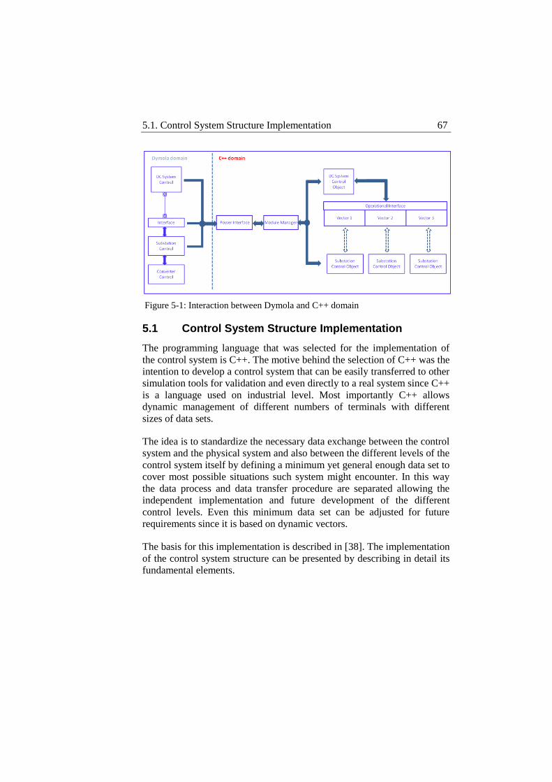
5.1. Control System Structure Implementation 67
Figure 5-1: Interaction between Dymola and C++ domain
5.1 Control System Structure Implementation
The programming language that was selected for the implementation of
the control system is C++. The motive behind the selection of C++ was the
intention to develop a control system that can be easily transferred to other
simulation tools for validation and even directly to a real system since C++
is a language used on industrial level. Most importantly C++ allows
dynamic management of different numbers of terminals with different
sizes of data sets.
The idea is to standardize the necessary data exchange between the control
system and the physical system and also between the different levels of the
control system itself by defining a minimum yet general enough data set to
cover most possible situations such system might encounter. In this way
the data process and data transfer procedure are separated allowing the
independent implementation and future development of the different
control levels. Even this minimum data set can be adjusted for future
requirements since it is based on dynamic vectors.
The basis for this implementation is described in [38]. The implementation
of the control system structure can be presented by describing in detail its
fundamental elements.
68 Chapter 5. Implementation
Operational Interface
The Operational Interface is the point of communication between the
different connected terminals and the overall Control System. It is, in this
sense, the point of communication between the DC System Control level
and the Substation Control level. Every Substation Control object (SCO)
outputs there all information related to its operation including
measurements, hand-shaking signals and system type information and
acquires from the Operational Interface operation commands or schedule
assigned to it by the DC System Control level. The DC System Control in
its turn receives all the information regarding the connected SCOs from
the Operational Interface that are necessary for the system analysis before
it outputs there all the commands addressing each individual SCO. It
should be pointed out at this point that the DC System Control has two
possibilities of controlling the different SCOs; it can either control them
directly by placing commands on the interface and monitoring each SCO’s
operation by the feedback it provides, or by placing a schedule in the
interface that the SCOs are expected to follow. From the DC System
Control perspective these two constitute clearly two distinct cases. At
direct control, DC System Control uses the output Operational Vector to
directly provide control commands to the different SCOs, while at indirect
control it uses the Schedule Vector to output an expected schedule
operation to each SCO. From the SCO perspective the cases are also
different; however the SCO provides its feedback through the Operational
Vector always. This means that regardless of the way a control command
was handed to the SCO, directly or indirectly, it will update DC System
Control in the same way, by updating the handshake signals in the
Operational Vector.
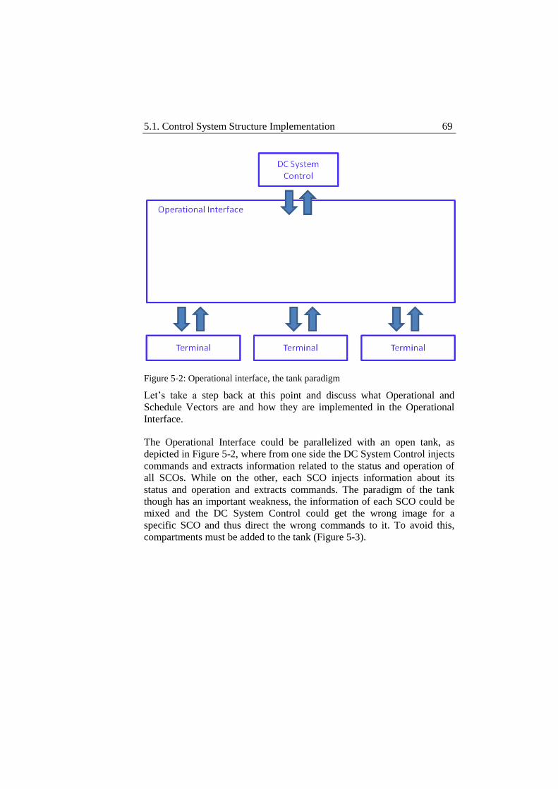
5.1. Control System Structure Implementation 69
Figure 5-2: Operational interface, the tank paradigm
Let’s take a step back at this point and discuss what Operational and
Schedule Vectors are and how they are implemented in the Operational
Interface.
The Operational Interface could be parallelized with an open tank, as
depicted in Figure 5-2, where from one side the DC System Control injects
commands and extracts information related to the status and operation of
all SCOs. While on the other, each SCO injects information about its
status and operation and extracts commands. The paradigm of the tank
though has an important weakness, the information of each SCO could be
mixed and the DC System Control could get the wrong image for a
specific SCO and thus direct the wrong commands to it. To avoid this,
compartments must be added to the tank (Figure 5-3).
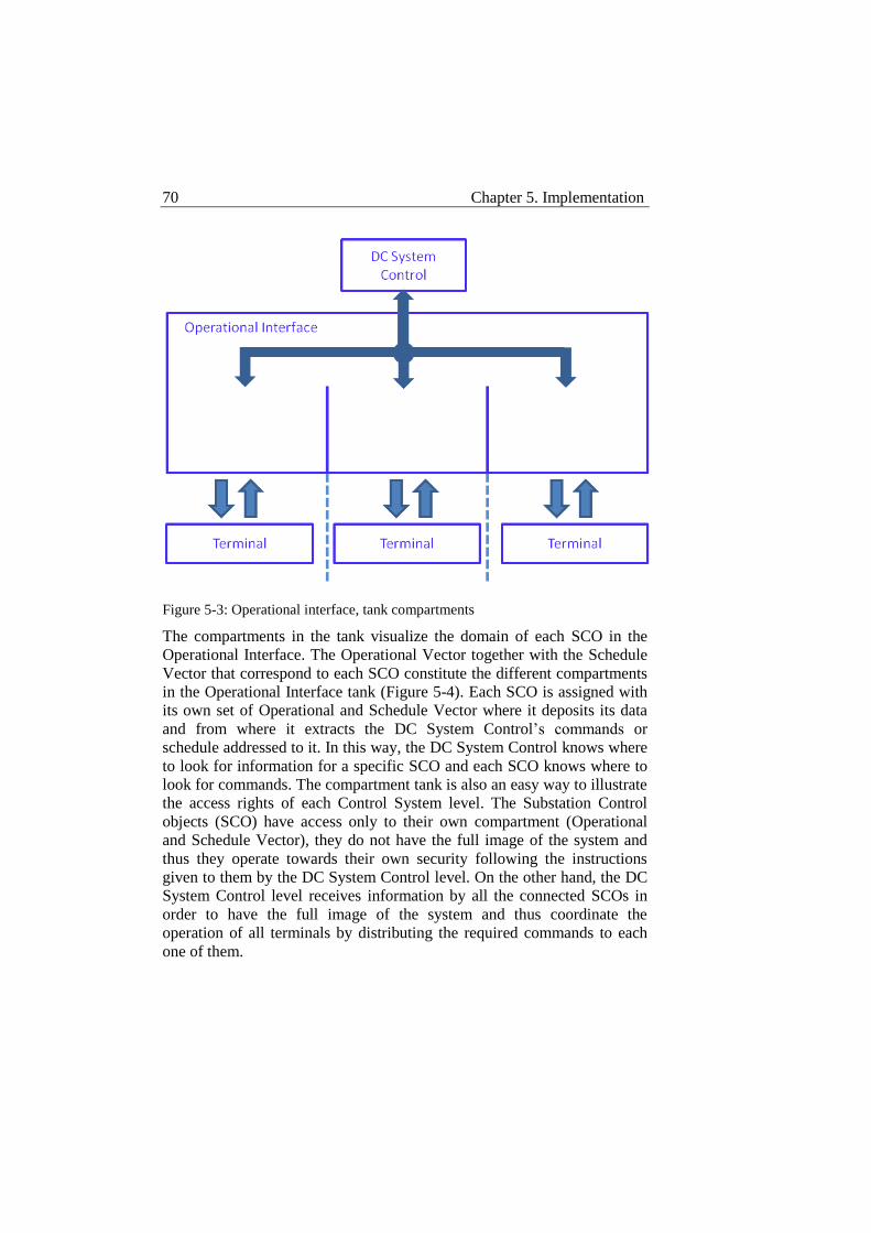
70 Chapter 5. Implementation
Figure 5-3: Operational interface, tank compartments
The compartments in the tank visualize the domain of each SCO in the
Operational Interface. The Operational Vector together with the Schedule
Vector that correspond to each SCO constitute the different compartments
in the Operational Interface tank (Figure 5-4). Each SCO is assigned with
its own set of Operational and Schedule Vector where it deposits its data
and from where it extracts the DC System Control’s commands or
schedule addressed to it. In this way, the DC System Control knows where
to look for information for a specific SCO and each SCO knows where to
look for commands. The compartment tank is also an easy way to illustrate
the access rights of each Control System level. The Substation Control
objects (SCO) have access only to their own compartment (Operational
and Schedule Vector), they do not have the full image of the system and
thus they operate towards their own security following the instructions
given to them by the DC System Control level. On the other hand, the DC
System Control level receives information by all the connected SCOs in
order to have the full image of the system and thus coordinate the
operation of all terminals by distributing the required commands to each
one of them.
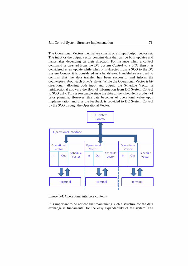
5.1. Control System Structure Implementation 71
The Operational Vectors themselves consist of an input/output vector set.
The input or the output vector contains data that can be both updates and
handshakes depending on their direction. For instance when a control
command is directed from the DC System Control to a SCO then it is
considered as an update while when it is directed from a SCO to the DC
System Control it is considered as a handshake. Handshakes are used to
confirm that the data transfer has been successful and inform the
counterparts about each other’s status. While the Operational Vector is bi-
directional, allowing both input and output, the Schedule Vector is
unidirectional allowing the flow of information from DC System Control
to SCO only. This is reasonable since the data of the schedule is product of
prior planning. However, this data becomes of operational value upon
implementation and thus the feedback is provided to DC System Control
by the SCO through the Operational Vector.
Figure 5-4: Operational interface contents
It is important to be noticed that maintaining such a structure for the data
exchange is fundamental for the easy expandability of the system. The
72 Chapter 5. Implementation
data are pooled together, sorted and directed to their destination without
requiring one physical input/output node between the DC System Control
and each SCO. As it will be discussed later on, the sorting of data is
handled by an identity system which is also based on a dynamically
managed structure. The combination of the dynamically managed identity
system and the dynamic Operational and Schedule Vectors provides the
flexibility to add as many SCOs as necessary and implement more
complex data sets without interfering with the implementation of the DC
System Control.
Apart from the structure of the Operational Interface, it is important to take
a look at the data set itself that is used for the implementation of the
Control System. While the individual signals may change within each
signal group, it is important that the signal functionality groups are kept
similar to what is suggested in the IEC 61850 standard [39-42].
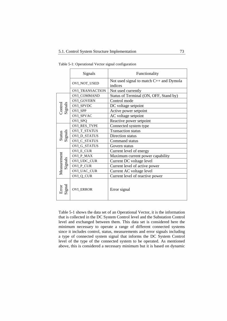
5.1. Control System Structure Implementation 73
Table 5-1: Operational Vector signal configuration
Signals Functionality
OVI_NOT_USED
Not used signal to match C++ and Dymola
indices
OVI_TRANSACTION Not used currently
Co
ntr
ol
Sig
nal
s
OVI_COMMAND Status of Terminal (ON, OFF, Stand by)
OVI_GOVERN Control mode
OVI_SPVDC DC voltage setpoint
OVI_SPP Active power setpoint
OVI_SPVAC AC voltage setpoint
OVI_SPQ Reactive power setpoint
Sta
tus
Sig
nal
s
OVI_RES_TYPE Connected system type
OVI_T_STATUS Transaction status
OVI_D_STATUS Direction status
OVI_C_STATUS Command status
OVI_G_STATUS Govern status
Mea
sure
men
t
Sig
nal
s
OVI_E_CUR Current level of energy
OVI_P_MAX Maximum current power capability
OVI_UDC_CUR Current DC voltage level
OVI_P_CUR Current level of active power
OVI_UAC_CUR Current AC voltage level
OVI_Q_CUR Current level of reactive power
Err
or
Sig
nal
OVI_ERROR Error signal
Table 5-1 shows the data set of an Operational Vector, it is the information
that is collected in the DC System Control level and the Substation Control
level and exchanged between them. This data set is considered here the
minimum necessary to operate a range of different connected systems
since it includes control, status, measurements and error signals including
a type of connected system signal that informs the DC System Control
level of the type of the connected system to be operated. As mentioned
above, this is considered a necessary minimum but it is based on dynamic
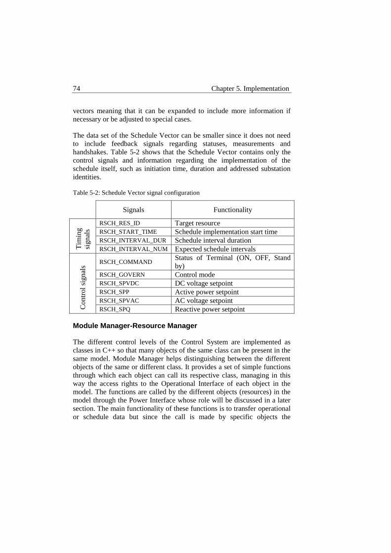
74 Chapter 5. Implementation
vectors meaning that it can be expanded to include more information if
necessary or be adjusted to special cases.
The data set of the Schedule Vector can be smaller since it does not need
to include feedback signals regarding statuses, measurements and
handshakes. Table 5-2 shows that the Schedule Vector contains only the
control signals and information regarding the implementation of the
schedule itself, such as initiation time, duration and addressed substation
identities.
Table 5-2: Schedule Vector signal configuration
Signals Functionality
Tim
ing
signal
s
RSCH_RES_ID Target resource
RSCH_START_TIME Schedule implementation start time
RSCH_INTERVAL_DUR Schedule interval duration
RSCH_INTERVAL_NUM Expected schedule intervals
Contr
ol
signal
s
RSCH_COMMAND Status of Terminal (ON, OFF, Stand
by)
RSCH_GOVERN Control mode
RSCH_SPVDC DC voltage setpoint
RSCH_SPP Active power setpoint
RSCH_SPVAC AC voltage setpoint
RSCH_SPQ Reactive power setpoint
Module Manager-Resource Manager
The different control levels of the Control System are implemented as
classes in C++ so that many objects of the same class can be present in the
same model. Module Manager helps distinguishing between the different
objects of the same or different class. It provides a set of simple functions
through which each object can call its respective class, managing in this
way the access rights to the Operational Interface of each object in the
model. The functions are called by the different objects (resources) in the
model through the Power Interface whose role will be discussed in a later
section. The main functionality of these functions is to transfer operational
or schedule data but since the call is made by specific objects the
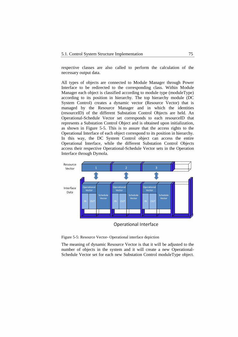
5.1. Control System Structure Implementation 75
respective classes are also called to perform the calculation of the
necessary output data.
All types of objects are connected to Module Manager through Power
Interface to be redirected to the corresponding class. Within Module
Manager each object is classified according to module type (moduleType)
according to its position in hierarchy. The top hierarchy module (DC
System Control) creates a dynamic vector (Resource Vector) that is
managed by the Resource Manager and in which the identities
(resourceID) of the different Substation Control Objects are held. An
Operational-Schedule Vector set corresponds to each resourceID that
represents a Substation Control Object and is obtained upon initialization,
as shown in Figure 5-5. This is to assure that the access rights to the
Operational Interface of each object correspond to its position in hierarchy.
In this way, the DC System Control object can access the entire
Operational Interface, while the different Substation Control Objects
access their respective Operational-Schedule Vector sets in the Operation
Interface through Dymola.
Figure 5-5: Resource Vector- Operational interface depiction
The meaning of dynamic Resource Vector is that it will be adjusted to the
number of objects in the system and it will create a new Operational-
Schedule Vector set for each new Substation Control moduleType object.
76 Chapter 5. Implementation
The respective DC System Control moduleType object will then
automatically gain access to it.
As mentioned above the function set provided by Module Manager is
simple and built to trigger only the more complex parts of the code.
mInit (moduleType, cv[], cvSize)
Arguments
moduleType: As mentioned above, moduleType defines the type
of each object as DC System Control, Substation Control or
Converter Control classifying accordingly each object in
hierarchical order.
Cv[]: Cv stands for configuration vector. It can host information
that the operator considers important for each object. The Control
System itself expects to receive some information by the cv[] such
as limits regarding maximum power, power ramping or current.
The size of the expected interface must also be defined in cv[] as
well as the type of the connected system (resourceType). In the
physical system a substation might connect to the DC system
different types of systems, such as wind power plants, loads or
onshore grids. For this reason the Substation Control object
handling each substation unit must have the information of the
type of the system that the substation unit connects to the DC
system. In this way the DC System Control is aware of the
available power mix in the system so that it can consider it in
scheduling. In the same way each Substation Control object can
have a better image of what safe operation is according to the
connected system.
cvSize: It contains the information of the size of cv[]. This
information is important and has to be included because it makes
cv[] adjustable to the requirements of each system.
Functionality
It can easily be conducted by the analysis of the arguments of the
mInit function that its purpose is to initialize the respective object.
5.1. Control System Structure Implementation 77
Every time it is called using a specific moduleType a new
resourceID is saved in the Resource Vector of the corresponding
moduleType. At the same time Module Manager creates a new
object by calling the constructor of the respective class. At the end
of this procedure a new object will be created and given a
resourceID which is also saved in the respective Resource Vector.
Cv[] is also provided by mInit as a set of information for the newly
created object that will accompany it after initialization also. Cv[]
is a source of fundamental information about each object that can
be accessed at any time.
mUpdate (moduleType, objectID, timeStamp)
Arguments
moduleType: Same as in mInit.
objectID: ObjectID refers to resourceID, the unique identity of
each object. This argument is used here since the mUpdate
function is supposed to be executed on the specific object that
calls for it. ModuleType places the object in hierarchy and
accordingly, Module Manager points the object to a specific class,
then objectID helps executing the update function within the class
for this specific object that will provide it with access rights over
the respective Operational-Schedule Vector set in the Operational
Interface.
timeStamp: TimeStamp is the time within the simulation tool.
Even if it has no relation with the navigation of the C++ program
in its own structure, it is a useful piece of information when time
dependent events affect the operation of the different classes.
Especially when Dymola is the simulation tool, it is used to force
Dymola to execute update and this is because timeStamp will
always change from sample to sample. Dymola might not execute
a function again if its arguments have not changed, by including
timeStamp it is guaranteed that the function will be executed even
for the same objectID.
78 Chapter 5. Implementation
Functionality
Update means recalculate here. It will use the input Operational or
Schedule Vector/s available, recalculate and fill the output
Operational Vector/s. Depending on the implementation of the
mUpdate function for each class the inputs and outputs might not
be updated within the mUpdate function, in such case mUpdate
must be preceded by a mSet function and followed by a mGet
function to make sure that mUpdate operates on the latest data
obtained by the system and outputs its data to the system. As for
the case of mInit, moduleType defines the position of the object in
hierarchy while objectID distinguishes it from other objects of the
same moduleType. Especially for mUpdate this will define which
Operational or Schedule Vector/s are available for it, since a DC
System Control object can receive input and provide output to all
connected Substation Control objects while Substation Control
objects can only interact with the Operational Vector that is
assigned to them.
mSet (moduleType, objectID, vectorType, value [], timeStamp)
Arguments
moduleType: Same as in previous functions.
objectID: Same as in previous functions.
vectorType: The vectorType argument defines whether the
function will operate on the input Operational Vector, the output
Operational Vector or the Schedule Vector of the above specified
object. VectorType can define 4 types of vectors, input
Operational Vector, output Operational Vector, Schedule Vector
and configuration vector. Although the mSet function can only
operate on the Operational Vector. More specifically, the
reasonable operation of mSet function is on the input Operational
Vector.
5.1. Control System Structure Implementation 79
value []: Value [] is a vector of data provided as an argument to be
transferred from the Dymola connector to the input Operational
Vector.
timeStamp: Same as in previous functions.
Functionality
The mSet function is used to receive inputs from Dymola domain
and transfer it to C++ domain. For any calculation to be made in
C++, information needs to be input by the physical system and
mSet provides the way to do so. Value [] is copied in the input
Operational Vector and thus must be arranged accordingly
beforehand, while moduleType and objectID locate the exact
Operational Vector to be changed within the Operational Interface.
mGet (moduleType, objectID, vectorType, index, value, timeStamp)
Arguments
moduleType: Same as in previous functions.
objectID: Same as in previous functions.
vectorType: Same as in mSet. For mGet function though the
reasonable operation is on the output Operational Vector or the
Schedule Vector.
index: For mGet, instead of providing the data to be transferred in
the form of a vector, the data is provided element by element and
this is the reason why it is necessary to specify in which position
of the output Operational or Schedule Vector each element must
be placed. As it can easily be guessed, for a data set to be copied
to the output Operational or Schedule Vector, mGet must be
within a “for” loop running all of the respective vector’s elements.
Although it might appear to have no particular meaning, this
procedure provides the possibility to randomly access and change
any element in the Operational Vector. This is necessary because
there are objects that only need to change few elements of the
80 Chapter 5. Implementation
Operational or Schedule Vector and not the entire vector. On the
other hand the important information in the output Operational or
Schedule Vector is commands and control signals which are
mainly digital and there is no need to update them if there is no
change. On the input Operational Vector which is manipulated by
the mSet function the most important information is
measurements. The measurements reach the Control System in
digital form but since they derive from analog signals they change
very often thus making their update in every sample a necessity.
value: Value is what is to be transferred to the index specified
position of the output Operational Vector.
timeStamp: Same in previous functions.
Functionality
The functionality of mGet is to extract the output Operational or
Schedule Vector of the moduleType and objectID indicated object
to the respective Dymola connector. This is done in an element by
element mode which makes imperative the use of a “for” loop
together with mGet if the entire output Operational or Schedule
Vector is to be copied to the Dymola connector. But in this way it
provides the possibility of selectively output specific elements of
the Operational Vector to substitute the previous values without
altering the rest. The role of mGet is as important as the role of
mSet and mUpdate since there would be no value in inputting data
to C++ domain and making any calculations there if there was no
way to output the results of these calculations to the system.
Module Manager provides the infrastructure for the interaction between
the different objects within the system. It applies a systematic
classification of each object according to type (moduleType), and thus
position in hierarchy which defines its access rights in the Operational
Interface, and identity (resourceID) which distinguishes each object from
other objects of the same type. It also consists of a simple function set that
can be called by the different objects in the system through the Power
Interface that will be discussed later on. The main principle of operation
for the function set for any object that uses it could be described in three
5.2. Control Levels Implementation 81
steps, update inputs (mSet), calculate (mUpdate) and update outputs
(mGet). It is important to mention that the implementation of each
function might change from class to class. Arguments like moduleType
and objectID are present in almost all functions and their sole role is to
allow Module Manager to choose the right implementation according to
the object that is calling for them.
Power Interface
Power Interface is mentioned here to avoid confusion with Uniform
Interface. Power interface does not have to do with the interfacing between
the different control levels of the control system described above. It serves
as the link between C++ code and the outer world, in this case Dymola.
Power Interface contains a function set like the one of Module Manager,
only this time all the functions are defined as external and they only call
the functions of Module Manager. In this way, Power Interface allows
internal functions to be called from outside the program indirectly. This
“buffer” stage is important so that external users of the program do not
interfere with C++ indices that the program uses to keep track of its
objects. Power interface takes care of any index mismatch between C++
and Dymola assuring that indices match and there is no index out of
boundaries. As in C++, in Dymola the functions of Power Interface must
have copies that are defined as external “C” functions and then be
imported in the correspondent Dymola class before they can be used.
5.2 Control Levels Implementation
The Control System is divided in three hierarchical levels and thus its
implementation in C++ follows the same structure. In the C++, each level
of the Control System is implemented as a separate class. In this way
many objects of the same class can be created in a system with Module
Manager keeping track of each one of them. The hierarchy in the Control
System is reflected in the access rights to the Operational Interface that
each class is given through its implementation. As will be shown later, the
access rights of each class is something programmed within each class
constituting in this way the Operational Interface as the common data node
for every class and thus for every object. Each class has the right to
manipulate the Operational Interface as a whole or parts of it (Operational-
Schedule Vectors).
82 Chapter 5. Implementation
DC System Control
DC System Control level is supposed to have a clear image of the system
as an entity in order to be able to make decisions for the coordination of
the different terminals and act towards this goal by distributing control
commands. To do so the DC System Control class has access to all input
and output Operational and Schedule Vectors within the Operational
Interface. In this way, DC System Control receives information by all
connected terminals in order to determine the status of the system and then
according to this manipulate the outputs heading to each terminal or
distribute schedule information to achieve the current control objectives.
The main idea is to implement the DC System Control level as a state
machine with the different states representing different stages in the
operation of the system. The intention is to represent the system as
accurately as possible through the different states and for this reason
different conditions have been used to determine the current state of the
system and also the transitions between the states. Consequently, the
operation of DC System Control class is divided in updating the conditions
from incoming measurements, updating the state according to the
conditions and updating the outputs according to state. It is important to
mention here that there is no need to update the inputs in DC System
Control class since this is taken care of by the uniform interfaces
connecting the different terminals. The functionality of the uniform
interface will be discussed later on.
In an effort to make the operation of the DC System Control general,
automated search functions have been used to handle the different
terminals according to their properties avoiding a direct reference to their
identity. Since the ambition is that the number of terminals should be
allowed to change, DC System Control must be adaptable. Thus, having a
resource vector that might vary in size it is not recommendable to use
direct references to the identities of the different objects in the system.
Instead, it is preferable to have some search function that will go through
the resource vector and find the object with the desired set of properties.
The function will then return the identity of the object for further
utilization. If direct identity references were to be used, the addition of a
new terminal in the system would imply the modification of the code of
DC System Control class or its de facto exclusion from the operation of

5.2. Control Levels Implementation 83
the system. Automated search functions are used through the different
parts of the DC System Control.
Conditions
If DC System Control is to be implemented as a state machine the
determination of the current state at each point of operation as well as
the transition between the different states is of vital importance. Of
course these conditions have to be related to external inputs for the
DC System Control to be connected to the reality of the physical
system. The different conditions are in the form of logical flags that
represent a specific situation in the physical system. Their state (true
or false) is determined by searching a specific group of resources or
all of the resources or one specific resource for specific properties.
The inputs for the different conditions come from the input
Operational Vectors to DC System Control by the different connected
Substation Control objects. This means that the signals that are taken
into account to determine the system’s state are measurements and
handshake signals, thus reflecting the real situation of the system both
in terms of measured quantities and control signals.
As mentioned above, the flags used are related both to measurements
from the physical system and handshake signals reflecting the control
status of the respective terminal or group of terminals. Table 5-3 lists
the status flags.
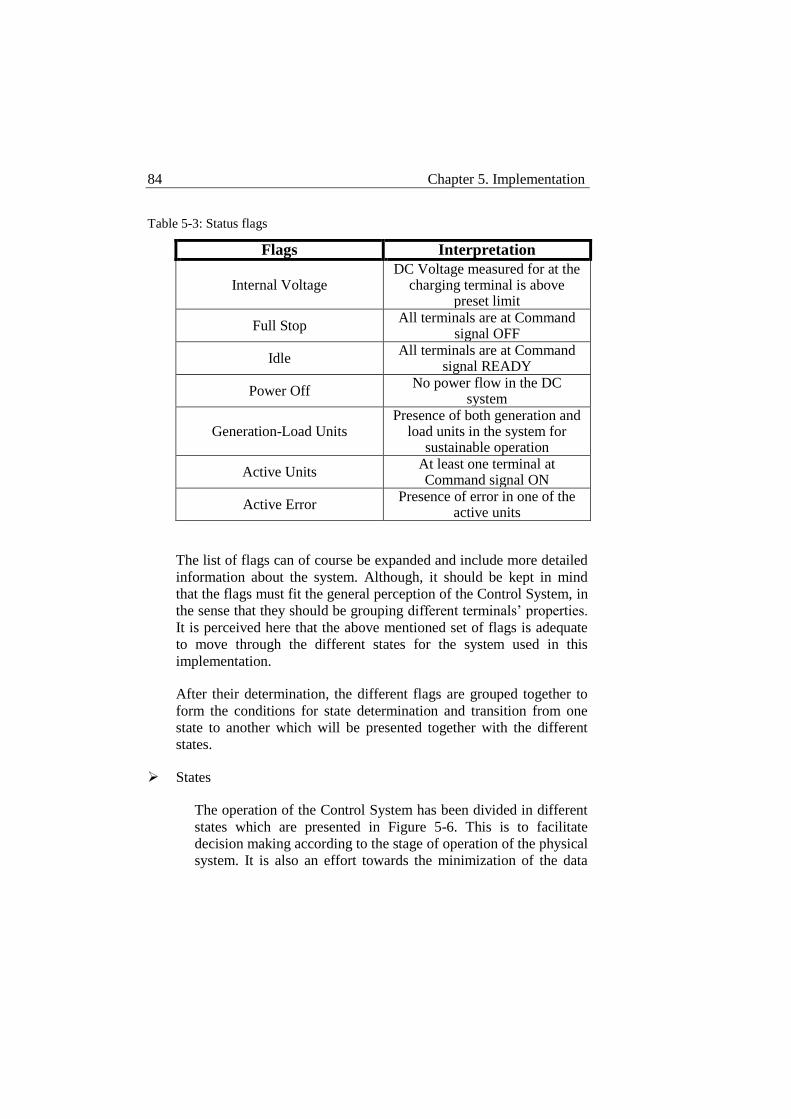
84 Chapter 5. Implementation
Table 5-3: Status flags
Flags Interpretation
Internal Voltage DC Voltage measured for at the
charging terminal is above preset limit
Full Stop All terminals are at Command
signal OFF
Idle All terminals are at Command
signal READY
Power Off No power flow in the DC
system
Generation-Load Units Presence of both generation and
load units in the system for sustainable operation
Active Units At least one terminal at Command signal ON
Active Error Presence of error in one of the
active units
The list of flags can of course be expanded and include more detailed
information about the system. Although, it should be kept in mind
that the flags must fit the general perception of the Control System, in
the sense that they should be grouping different terminals’ properties.
It is perceived here that the above mentioned set of flags is adequate
to move through the different states for the system used in this
implementation.
After their determination, the different flags are grouped together to
form the conditions for state determination and transition from one
state to another which will be presented together with the different
states.
States
The operation of the Control System has been divided in different
states which are presented in Figure 5-6. This is to facilitate
decision making according to the stage of operation of the physical
system. It is also an effort towards the minimization of the data
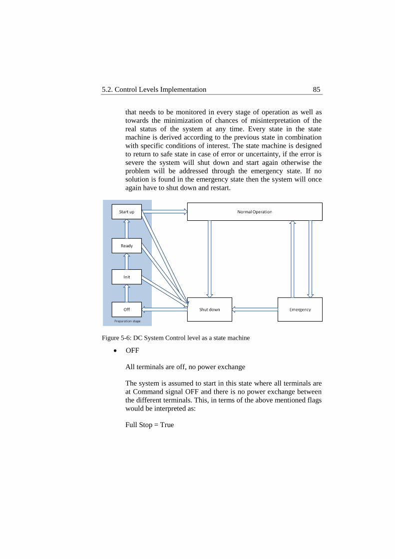
5.2. Control Levels Implementation 85
that needs to be monitored in every stage of operation as well as
towards the minimization of chances of misinterpretation of the
real status of the system at any time. Every state in the state
machine is derived according to the previous state in combination
with specific conditions of interest. The state machine is designed
to return to safe state in case of error or uncertainty, if the error is
severe the system will shut down and start again otherwise the
problem will be addressed through the emergency state. If no
solution is found in the emergency state then the system will once
again have to shut down and restart.
Figure 5-6: DC System Control level as a state machine
OFF
All terminals are off, no power exchange
The system is assumed to start in this state where all terminals are
at Command signal OFF and there is no power exchange between
the different terminals. This, in terms of the above mentioned flags
would be interpreted as:
Full Stop = True
86 Chapter 5. Implementation
The condition for transition to the next state is a timer expiration
and an external operator signal. The external operator signal must
be activated for the system to restart its operation automatically. If
for some reason the operation of the system must be discontinued
the timer will give some time to the operator to deactivate the
external signal
Timer OFF = True
Operator signal = True
From OFF state and given that the conditions for transition hold
the system will proceed to the next state.
INIT
Terminal availability check, all error free terminals are set to
’ready’ (stand by).
The conditions for the system to be in this state are that it has
previously been in OFF state, Timer OFF has expired and the
Operator signal remained true.
For the system to proceed to the next state, first, error free
generation and load units must be identified in the system and then
at least one of them must be at Command signal READY. All
error free terminals must be at Command signal READY and
some of them must be generation units while others must be load
units. The reason why there must be error free terminals in the
system is quite straight-forward since no operation can start
without them. The error free terminals must be at READY,
standing by for operation. Generation and load units must be
among the READY error free terminals to justify sustainable
operation. In terms of flags this would be interpreted as:
Generation-Load Units = True
Idle = True
Error Free = True
5.2. Control Levels Implementation 87
From INIT state and given that the conditions for transition hold
the system will proceed to the next state.
READY
One or more ’ready’ terminals are selected to charge the DC link.
If the system is at this state, it means that there are both error free
generation and load units standing by for operation.
The functionality of this state is to select one or more of the
generation units to charge the DC link so that any power exchange
can take place. Charging the DC link is a shared responsibility
among all READY active terminals operating at DC droop control.
It is obvious that no passive connected network can participate in
this procedure. More criteria can be added for this operation to
include prioritized terminals for this purpose and implement
potential agreements between the involved parts. For instance, DC
voltage control could be used for a specific terminal to charge the
DC link, if existing agreements dictate so. To signal this to the rest
of the system a flag turns true that shows that there are active units
now in the system. Since the DC link is not charged yet, no power
exchange can exist among the connected terminals and thus, this
flag indicates that the system is taking action, requesting different
terminal to get active in preparing the normal operation of the
system. In terms of flags this would be interpreted as:
Active Units = True
When this flag becomes true, the system automatically proceeds to
the next state.
START UP
One or more terminals are charging the DC link, wait until DC
link is charged.
When the system enters this state, there are already one or more
terminals charging the DC link. What is necessary at this point is
to monitor the DC link voltage and when its lower limit is reached
88 Chapter 5. Implementation
the system can proceed to the next state. When the DC link is
charged the internal voltage flag becomes true. If the active units
continue being error free the transition to next state is signaled.
Internal Voltage = True
Active Error = False
When Internal Voltage is true and if there is no error in the active
terminals the system is ready to begin power exchange between
the different terminals, thus schedule implementation can start.
NORMAL OPERATION
Schedule is implemented.
When the system arrives at this state it is ready to start the
implementation of the required schedule. All conditions are
present to begin the normal operation of the system, the DC link is
charged and error free generation and load units are present in the
system.
As mentioned in earlier sections, DC System Control can either
control the different substations directly through the Operational
Vectors or indirectly through the Schedule Vectors. Up to this
state DC System Control operates the different substations
directly, assigning control commands and setpoints in an effort to
coordinate their operation to prepare the system for schedule
implementation. When the system enters this state the control
becomes indirect. Schedule is an input to DC System Control,
which has to divide it and distribute it to the concerning
substations. DC System Control instead of controlling the different
substations through the Operational Vectors, it distributes the
schedule to the different substations through the Schedule Vectors.
Each substation receives the schedule it needs to implement for the
coming two intervals by DC System Control. The schedule itself
contains the information about the duration of its intervals and the
starting time. In this way, both DC System and Substation Control
know when to shift the schedule interval under implementation

5.2. Control Levels Implementation 89
and the pending one. The operation of DC System Control is to
read and send the schedule interval to the corresponding
substation. DC System Control is always looking at one schedule
interval ahead of the one that is implemented. As shown in Figure
5-7, every time a schedule interval expires, DC System Control
reads and distributes the next. In the Substation Control there are
two positions for the schedule intervals, one holding the schedule
interval under implementation and the other holding the pending
schedule interval. When a schedule interval expires, Substation
Control has to discard the implemented interval and shift the
interval in pending position to implementation position. In this
way, the transition from one interval to another is made and also
the pending interval position is freed to receive the next interval
that DC System Control sends. Timing information in the schedule
is important to achieve the synchronization of operations in DC
System and Substation Control and avoid data collision or loss.
Figure 5-7: Schedule distribution implementation
The advantage of distributing the schedule to the different
substations is that DC System Control is released from operational
duties and can focus on its supervisory role, on one hand. On the
other hand, having the substations aware of their expected
operation makes the system less vulnerable to communication loss.
In this implementation the substations are aware of two schedule
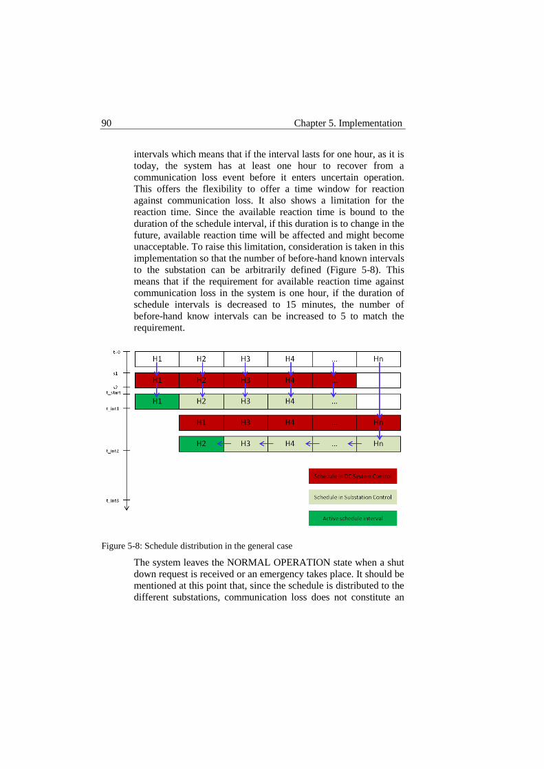
90 Chapter 5. Implementation
intervals which means that if the interval lasts for one hour, as it is
today, the system has at least one hour to recover from a
communication loss event before it enters uncertain operation.
This offers the flexibility to offer a time window for reaction
against communication loss. It also shows a limitation for the
reaction time. Since the available reaction time is bound to the
duration of the schedule interval, if this duration is to change in the
future, available reaction time will be affected and might become
unacceptable. To raise this limitation, consideration is taken in this
implementation so that the number of before-hand known intervals
to the substation can be arbitrarily defined (Figure 5-8). This
means that if the requirement for available reaction time against
communication loss in the system is one hour, if the duration of
schedule intervals is decreased to 15 minutes, the number of
before-hand know intervals can be increased to 5 to match the
requirement.
Figure 5-8: Schedule distribution in the general case
The system leaves the NORMAL OPERATION state when a shut
down request is received or an emergency takes place. It should be
mentioned at this point that, since the schedule is distributed to the
different substations, communication loss does not constitute an
5.2. Control Levels Implementation 91
emergency. The system is expected to continue its operation
unaffected by a communication loss event and communication loss
events are assumed not to last longer than a schedule interval.
SHUT DOWN
All terminals are turned off.
The system enters this state when there is an end of operation
request by the schedule under implementation or a severe error in
normal operation or an unresolved issue in emergency operation.
After this state the system will return to OFF state when all power
exchange has stopped between the different terminals and the DC
link voltage is at zero. In terms of flags this would be interpreted
as:
Full Stop = True
After shutting down the system will return to its initial state and
try to start again unless a different operator signal is provided.
EMERGENCY
One or more terminals have sent an error signal. There is at least
one error-free terminal in operation.
Emergency condition is considered an external disturbance to the
system. Since communication loss is not considered an emergency
in this implementation and DC breakers are absent so that a DC
fault must be handled by the AC protection systems, emergency
conditions that this system can handle are AC disturbances
affecting the operation of the HVDC system. The AC disturbances
that this system deals with are 3-phase AC faults that are
considered to be the most severe.
When a 3-phase fault happens in the AC side of each of the
terminals, after it takes action automatically to protect its
equipment, it will send an error signal to DC System Control. DC
92 Chapter 5. Implementation
System Control enters EMERGENCY state when an error signal is
detected.
If no error-free terminal remains in the system, DC System
Control will proceed to SHUT DOWN, otherwise it will try to
coordinate the remaining terminal so that the system remains
operational until the error is removed and return to NORMAL
OPERATION is possible.
It is important to mention here that all different states are protected by a timer. This is to certify that the system will never get stuck in any state. In case the respective timer has expired in any state the system will go to SHUT DOWN state to stop any operation and start again.
Outputs
Each state has its own duties during operation. The different flags signify the transitions between the different states and then in every state different actions are taken that eventually affect the flags. In a way flags resemble sensors while states resemble actuators. A state reflects a set of conditions in the system and thus has to perform the necessary tasks according to the conditions of the system.
OFF
At OFF state there is no power flow within the DC system and the DC link voltage is zero. All the terminals are then turned into STOP Command signal to prepare them for the new start up operation. This state accesses all Operational Vectors and changes their output Command signal to STOP. This signal returns as a handshake signal in the input Operational Vector of every terminal after the command has been implemented and updates the respective flags in the system. The updated flags will then signal the transition to next state.
INIT
At INIT state all terminals are at STOP Command signal. The system in this state will first perform an availability check in all
5.2. Control Levels Implementation 93
terminals. This in practice means that the system will go through all Operational Vectors and search for errors at the OVI_ERROR position of the vector. Then, among the error free terminals it will search for generation and load units. It will search in all Operational Vectors at OVI_RES_TYPE position for generation and load units. It will acquire their identities and separate them in two vectors, one holding the identities of generation units and the other holding the identities of load units. At the end it will go through all the stored identities in both vectors and access their respective output Operational Vectors to change their Command signal from STOP to READY. In this way INIT state sets all the error free units at stand by given that there are both generation and load units. The commands will get distributed to the different terminals and handshake signals will occur to update the respective flags. The updated flags will allow the transition to the next state.
READY
When the system enters in READY state there are stand by units in the system waiting for operation. The task that READY state performs is that among the stand by units it chooses one or more to charge the DC link. It is obvious that the selected unit must be a generation unit and not a load unit. READY state uses the identity vector filled in INIT state that holds the identities of generation units. The selected units will then be commanded to start operation in DC droop control mode at a specific setpoint. For this to take place, the respective output Operational Vectors are accessed and changed in several positions so that command signals, control mode signals and setpoints are set to the correct values. In the same manner as before the affected signals will be transferred to the terminals where handshake signal will occur to update the respective flags and signal transition to next state.
START UP
When the system enters the START UP state there are one or more terminals charging the DC link. START UP state does not change any control signal since its task is to simply monitor the DC link voltage. The DC link voltage changes due to action taken in the previous state and the respective flag is updated independently of the state. It seems that READY and START UP states could be
94 Chapter 5. Implementation
one but if this was the case unnecessary identical changes would happen in the different Operational Vectors wasting computing resources. In this sense START UP is an idle state where the system waits for the actions taken in READY state to affect the physical system.
NORMAL OPERATION
In this state the DC link is already charged, one or more terminals are set to DC droop control holding the DC voltage and other terminals are at stand by for operation. The system is then ready to input the required schedule and start implementing it. In NORMAL OPERATION the direct control of the substations by DC System Control ceases. Operational Vectors are not used to transfer control commands anymore, instead, Schedule Vectors distribute schedule intervals to the substations where they are interpreted in control commands. DC System Control updates the schedule interval and supervises the entire system according to data it receives by the Operational Vectors in case it needs to intervene to resolve an emergency. It is important to mention here that every terminal is called in the schedule with an externally given identity which is not necessarily the same as the one the Resource Vector holds. For this reason a special function is used to relate the externally given identities which are unknown to the Control System to the internally given identities of the different objects that are classified in the Resource Vector.
SHUT DOWN
At SHUT DOWN state all terminals receive the command to stop operation, which in terms of signals is changing the value of OVI_COMMAND to COMMAND_STOP.
EMERGENCY
An emergency is detected by the error signal in the uniform
interface. When an error signal is received, DC System Control
moves to the EMERGENCY state. It is assumed then that the
faulted substation has already taken action to protect its equipment
and that it will not allow DC System Control to operate it until the
error is removed. Since the normal control mode of the substations
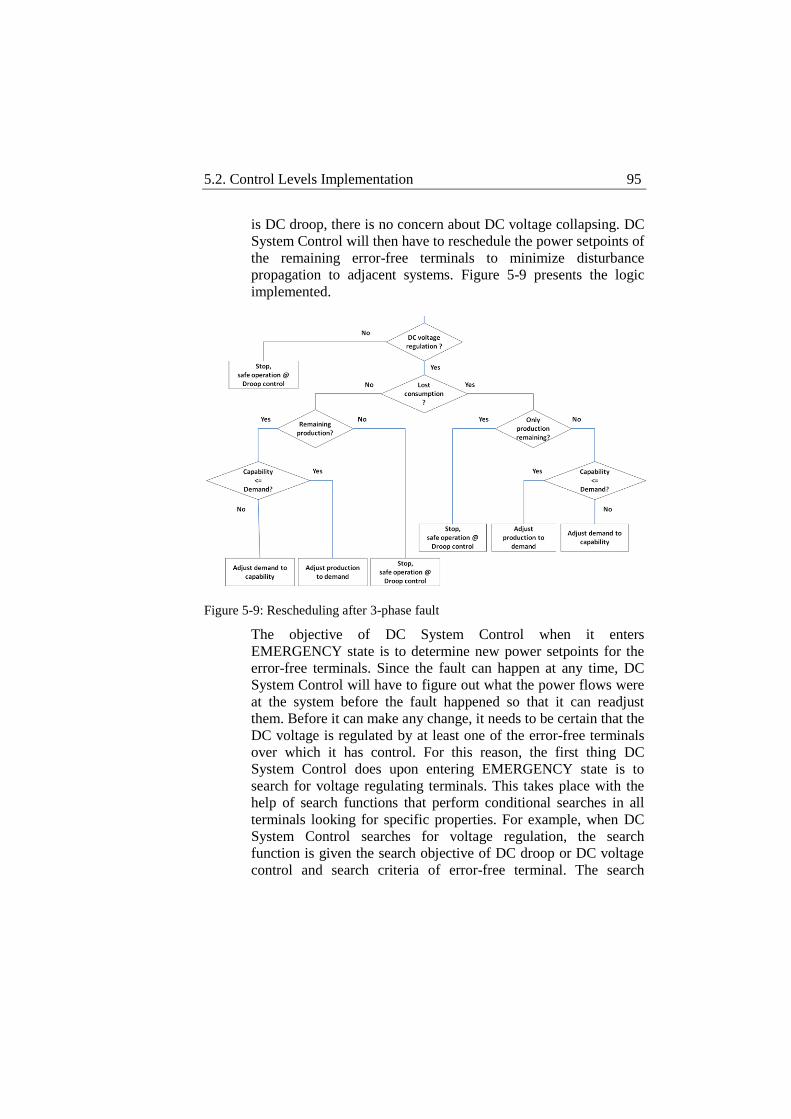
5.2. Control Levels Implementation 95
is DC droop, there is no concern about DC voltage collapsing. DC
System Control will then have to reschedule the power setpoints of
the remaining error-free terminals to minimize disturbance
propagation to adjacent systems. Figure 5-9 presents the logic
implemented.
Figure 5-9: Rescheduling after 3-phase fault
The objective of DC System Control when it enters
EMERGENCY state is to determine new power setpoints for the
error-free terminals. Since the fault can happen at any time, DC
System Control will have to figure out what the power flows were
at the system before the fault happened so that it can readjust
them. Before it can make any change, it needs to be certain that the
DC voltage is regulated by at least one of the error-free terminals
over which it has control. For this reason, the first thing DC
System Control does upon entering EMERGENCY state is to
search for voltage regulating terminals. This takes place with the
help of search functions that perform conditional searches in all
terminals looking for specific properties. For example, when DC
System Control searches for voltage regulation, the search
function is given the search objective of DC droop or DC voltage
control and search criteria of error-free terminal. The search
96 Chapter 5. Implementation
function will then go through the Resource Vector, search one by
one all terminals according to their identity in the Resource Vector
and return the identities of the terminals that fulfill the specified
criteria. After voltage regulation is confirmed by DC System
Control, it will proceed to specify whether the faulted terminal was
producing or consuming power. In a 3-terminal system, a
consuming faulted terminal shows that there is at least one
producing terminal left in the system. If there is only one
producing terminal left in the system, it means that it was the one
feeding the other two which means that it can keep feeding the
remaining consuming terminal with no problem. DC System
Control will then adjust the producing terminal’s output to the new
demand of the system after the consumption loss. In the case that
both the remaining terminals are producing, the only demand in
the system was the faulted terminal’s demand. Since the faulted
terminal cannot absorb any power the demand in the system is
zero and thus the output of the two producing terminal must be set
to zero as well. Power flows are adjusted in a similar way when
the faulted terminal was producing power. If the remaining
terminals are both consuming, since there is no power production
in the system their power setpoints will be set to zero. If there is
one remaining producing terminal its output will be adjusted to the
demand if it is within its capability, otherwise demand will be
adjusted at its maximum power output.
The intention of DC System Control at this state is not to preserve
DC voltage, since this is taken care of by DC droop. Its intention is
to make sure no other terminal will trip because of the automatic
loss sharing imposed by DC droop which will disregard the
maximum capabilities of the terminals to balance the DC voltage.
By adjusting the power setpoints DC System Control prevents DC
droop from forcing another terminal out of its limits in an effort to
distribute the power deficit and preserve DC voltage.
It is important to mention at this point that for DC System Control
to achieve this quick adjustment it assumes Operational control
over the terminal directly manipulating control modes and
setpoints. Anyway the schedule has no practical value at this point
since the system is not the same. If the timeline of actions is
5.2. Control Levels Implementation 97
considered, one can observe that the primary objective when a
fault happens is first of all, to protect equipment that will allow
continuation of operation when the fault is removes. Then, DC
droop is used to preserve DC voltage so that the rest of the
terminal can continue their operation which will be adjusted.
Finally, DC System Control readjusts the power setpoints of the
remaining terminals to avoid cascade tripping.
Substation Control
Substation Control level is implemented as a separate class in C++ to
assure the safe operation of the different substations in the system
following the control commands or the schedule delivered to them by DC
System Control level. Since it is implemented as a class, there will be one
object (SCO) of this class for each substation in the system. Each SCO is
an independent unit responsible for the safe operation of its respective
substation. Since the SCOs have only local authority, they are not in the
position to be aware of the entire system, thus coordination is needed and
provided to them by DC System Control. An Operational-Schedule Vector
set is assigned to each SCO at initialization. The SCOs are connected to
DC System Control through the uniform interfaces and to their respective
Converter Control level that will be discussed in a later section.
The duty of a SCO is to follow the operation instructions provided to it by
DC System Control. Its first priority though is to protect its equipment. For
this reason it will only follow instructions as long as it operates within safe
limits. When, for example, a 3-phase fault happens on the AC side of the
substation and its current suddenly rises, it will control the converter
towards keeping the current within its safe operation limits regardless of
any control requests by DC System Control. At the same time it will
generate an error signal so that DC System Control is aware that it can no
longer control the specific SCO. DC System Control will then have to try
to reschedule the power flows in the system to first, prevent other
substations from tripping due to changed power flows and secondly, to try
to relieve the faulted substation.
The SCOs can be directly or indirectly controlled by DC System Control.
When in normal operation, the SCO receives the schedule it has to
implement through the Schedule Vector, while during start up or
98 Chapter 5. Implementation
emergency and as long as it is not under direct threat of safety limits
breach DC System Control assumes direct control over the SCO through
the Operational Vector. The SCO interprets the condensed information
contained in the uniform interface that connects it to DC System Control
to the signals that are necessary for Converter Control. It also receives the
measurements obtained by Converter Control and arranges them in the
uniform interface for DC System Control to receive them. All
measurements from both sides of the substation are obtained at Converter
Control level since it is the one performing the continuous control of the
converter. They are then forwarded to the respective SCO where they are
sorted and placed in the right order in the interface for DC System Control.
Since Substation Control translates DC System Control’s control
commands for Converter Control, it is important that all three “speak the
same language”, meaning that control modes requested by DC System
Control must be recognized by Substation Control and supported by
Converter Control.
It becomes clear at this point that Substation Control plays the role of the
“bridge” between the continuous control of the converter performed by
Converter Control and the overall coordination performed by DC System
Control. It is responsible for the safe operation of the substation as a unit
and it is responsible for preparing the interfacing with DC System Control.
Substation Control could be implemented in other ways as long as it
follows the interfacing pattern of the uniform interface and Converter
Control can also be implemented in different ways as long as it is able to
communicate with Substation Control and fulfill its duties. The point here
is that since Substation Control and Converter Control only have local
authority, their implementation is indifferent to DC System Control as
long as they are able to communicate with each other, the interfacing rules
with DC System Control are followed and they fulfill their expected
functionality. This means that different equipment suppliers can operate
under the same DC System Control as long as the uniform interfacing
pattern is followed. Also, since substations are delivered as units,
communication between Substation Control and Converter Control is up to
the supplier to be determined without influencing the operation of DC
System Control.
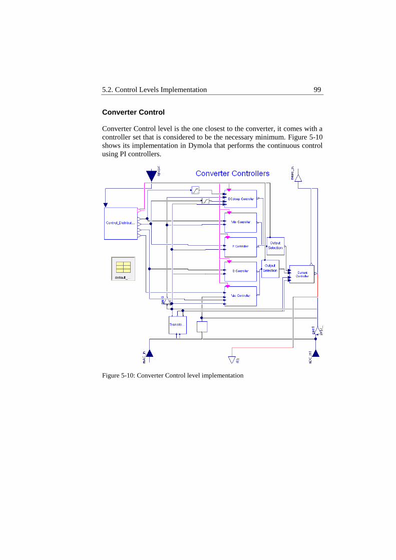
5.2. Control Levels Implementation 99
Converter Control
Converter Control level is the one closest to the converter, it comes with a
controller set that is considered to be the necessary minimum. Figure 5-10
shows its implementation in Dymola that performs the continuous control
using PI controllers.
Figure 5-10: Converter Control level implementation
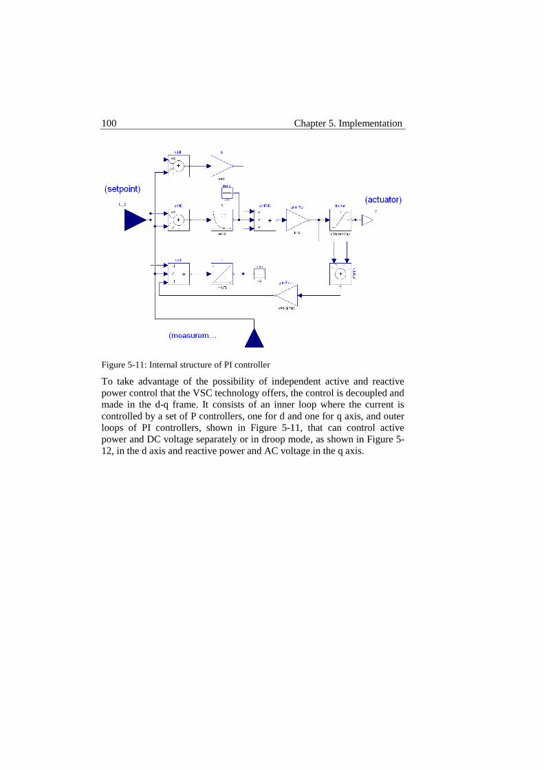
100 Chapter 5. Implementation
Figure 5-11: Internal structure of PI controller
To take advantage of the possibility of independent active and reactive
power control that the VSC technology offers, the control is decoupled and
made in the d-q frame. It consists of an inner loop where the current is
controlled by a set of P controllers, one for d and one for q axis, and outer
loops of PI controllers, shown in Figure 5-11, that can control active
power and DC voltage separately or in droop mode, as shown in Figure 5-
12, in the d axis and reactive power and AC voltage in the q axis.
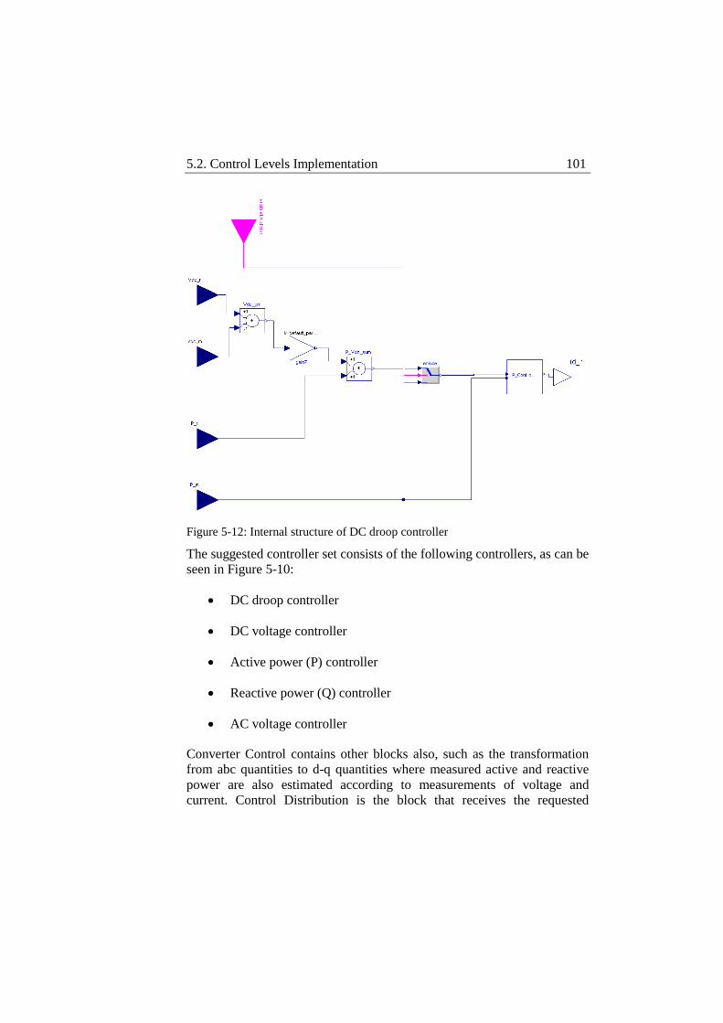
5.2. Control Levels Implementation 101
Figure 5-12: Internal structure of DC droop controller
The suggested controller set consists of the following controllers, as can be
seen in Figure 5-10:
DC droop controller
DC voltage controller
Active power (P) controller
Reactive power (Q) controller
AC voltage controller
Converter Control contains other blocks also, such as the transformation
from abc quantities to d-q quantities where measured active and reactive
power are also estimated according to measurements of voltage and
current. Control Distribution is the block that receives the requested
102 Chapter 5. Implementation
control modes and setpoints by Substation Control and then distributes it
to the respective controllers. Setpoints are classified in d axis setpoints and
q axis setpoints in Control Distribution and are thus sent to all d axis
controllers and q axis controllers respectively. To avoid confusion among
the different controllers, Control Distribution also controls an enable
signal for each controller. In this way it enables the controllers that must
operate at each time while the rest are disabled. Simulation time is also
saved in this way since the integral parts of the controllers would consume
a lot of computing power if they were to operate on a false setpoint that
they do not actually control.
Measurements from the system are collected in this level and converted to
per unit according to the parameters defined for the system. The per unit
values are used by the different controllers in this level and then forwarded
to Substation control and from there to DC System Control.
5.3 Physical System Model
The control system of a multi-terminal VSC-HVDC system, which is the
focus of this work, was discussed in detail up to this point. It was first
described conceptually as an abstract structure with the properties it must
feature and then its proposed implementation was described in detail
regarding all the tasks it needs to perform and the manner they are
distributed in the different control levels, the responsibility domains of the
different control levels and the way they interface among each other. It is
now time to test the functionality of the proposed system. For this reason a
system model is necessary.
Before defining an adequate model for the control system to be tested, it
needs to be considered what the objectives of this test are, what is to verify
concerning the control system. Test objectives can be classified in two
categories, structural and operational. Structural test objectives are related
to the modularity and expandability of the control system. Operational test
objectives are related to the efficiency of the implementation of the
different control levels to operate the multi-terminal system safely. The
test objectives will influence the definition of the adequate physical system
model as well as the selected simulation scenarios.
In the context of structural test objective the control system is tested for its
ability to integrate additional terminals. This tests the correct propagation
5.3. Physical System Model 103
of signals through the uniform interface, and confirms the expandability of
the control system with no required modification at its code. For this
category of test objectives there is no need for a detailed model since what
is to be tested is the correct flow of information through the different
control levels and the functionality of the uniform interface to assure the
modularity of the control system and thus its expandability.
In the context of operational test objectives the control system is tested for
its ability to implement the requested power flows by the schedule. Stable
operation and smooth transition from one power flow to another are
required. The control system is also put through abnormal conditions such
as communication loss and 3-phase faults on the AC side in an effort to
investigate the effect of those disturbances in the stability of the system.
For this category, power flows and voltage changes need to be closely
followed thus a more detailed model is necessary.
In both cases the intention is to validate the functionality of the proposed
control system and since no optimal operation is considered at this point,
the modeled physical system does not need to be complex. A 3-terminal
VSC-HVDC system will be considered in two different levels of detail
following the needs of the two test objective categories and the actual
timeline of the development of the proposed control system.
Test model
As discussed above to test the structural properties of the system there is
no need for a complex model. The intention at this point is to validate the
correct propagation of signals from one control level to another and prove
the functionality of the uniform interface. Accurate power flows and
realistic ratings are not critical at this point, what matters is to track the
different control signals and confirm that they are correct and reach their
target. Following the timeline of development of the proposed control
system, this simple model was built for a quick confirmation of the control
system structure before too much effort was put on programming the
different control levels. At this stage, the simple model also helped in
defining a minimum necessary data set for the uniform interface. It should
be mentioned at this point that after the structure is validated the content of
the different parts can be changed. This means that the implementation of
the different control levels can be changed as well as the content of the
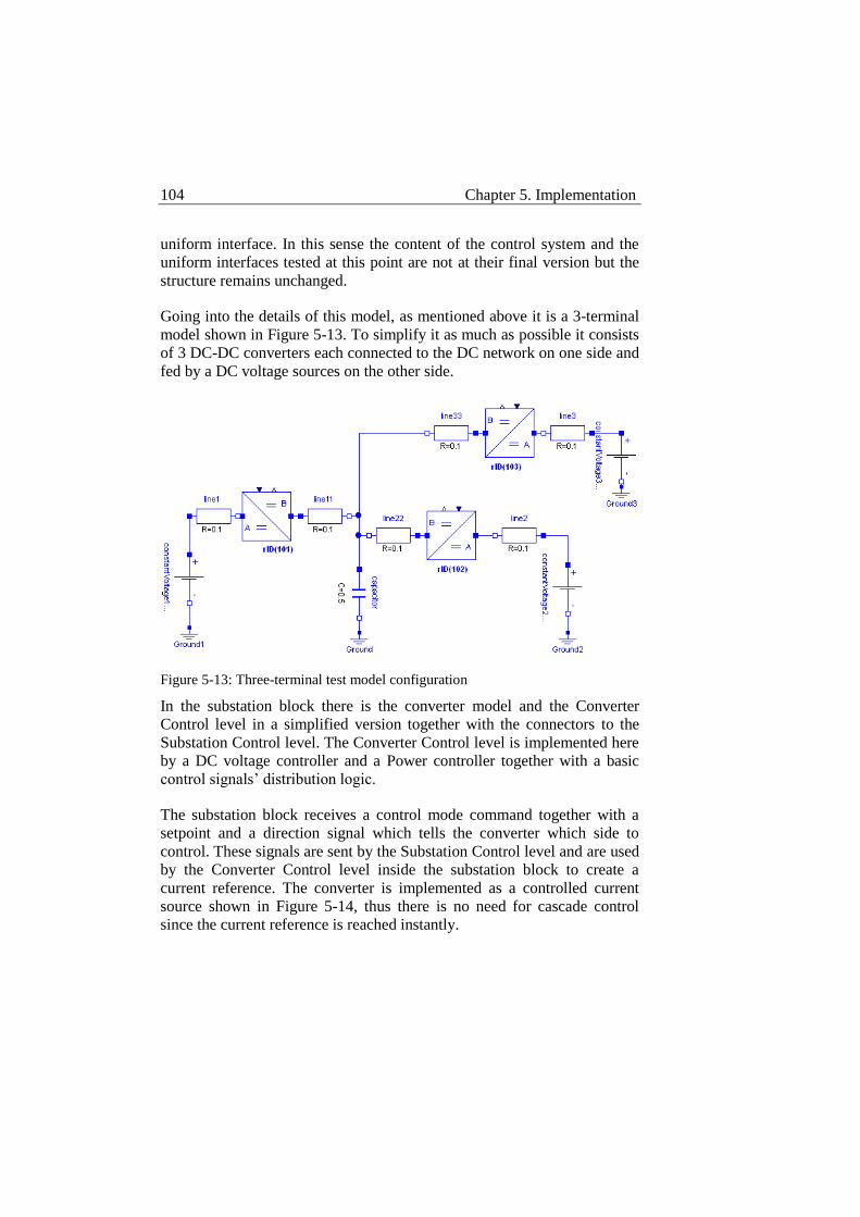
104 Chapter 5. Implementation
uniform interface. In this sense the content of the control system and the
uniform interfaces tested at this point are not at their final version but the
structure remains unchanged.
Going into the details of this model, as mentioned above it is a 3-terminal
model shown in Figure 5-13. To simplify it as much as possible it consists
of 3 DC-DC converters each connected to the DC network on one side and
fed by a DC voltage sources on the other side.
Figure 5-13: Three-terminal test model configuration
In the substation block there is the converter model and the Converter
Control level in a simplified version together with the connectors to the
Substation Control level. The Converter Control level is implemented here
by a DC voltage controller and a Power controller together with a basic
control signals’ distribution logic.
The substation block receives a control mode command together with a
setpoint and a direction signal which tells the converter which side to
control. These signals are sent by the Substation Control level and are used
by the Converter Control level inside the substation block to create a
current reference. The converter is implemented as a controlled current
source shown in Figure 5-14, thus there is no need for cascade control
since the current reference is reached instantly.
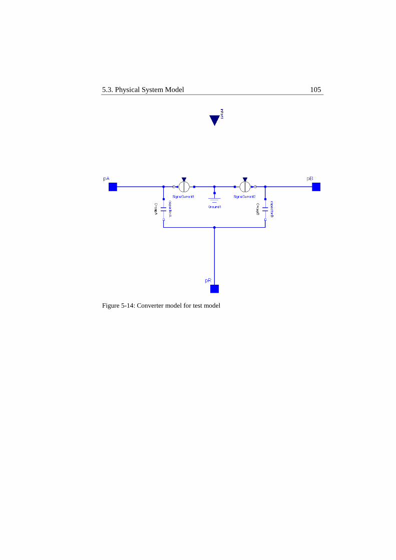
5.3. Physical System Model 105
Figure 5-14: Converter model for test model
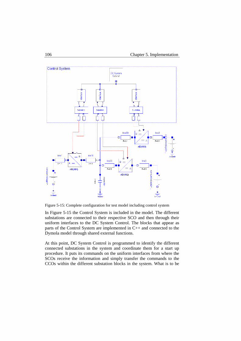
106 Chapter 5. Implementation
Figure 5-15: Complete configuration for test model including control system
In Figure 5-15 the Control System is included in the model. The different
substations are connected to their respective SCO and then through their
uniform interfaces to the DC System Control. The blocks that appear as
parts of the Control System are implemented in C++ and connected to the
Dymola model through shared external functions.
At this point, DC System Control is programmed to identify the different
connected substations in the system and coordinate them for a start up
procedure. It puts its commands on the uniform interfaces from where the
SCOs receive the information and simply transfer the commands to the
CCOs within the different substation blocks in the system. What is to be
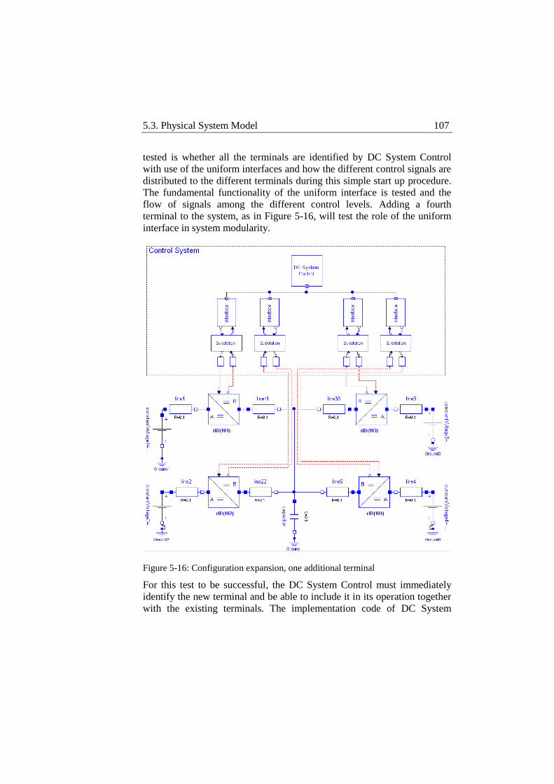
5.3. Physical System Model 107
tested is whether all the terminals are identified by DC System Control
with use of the uniform interfaces and how the different control signals are
distributed to the different terminals during this simple start up procedure.
The fundamental functionality of the uniform interface is tested and the
flow of signals among the different control levels. Adding a fourth
terminal to the system, as in Figure 5-16, will test the role of the uniform
interface in system modularity.
Figure 5-16: Configuration expansion, one additional terminal
For this test to be successful, the DC System Control must immediately
identify the new terminal and be able to include it in its operation together
with the existing terminals. The implementation code of DC System
108 Chapter 5. Implementation
Control shall not change to include the new terminal- connecting the new
terminal through the uniform interface must be enough for the operation of
the new terminal within the existing system. This will prove the structural
functionality of the uniform interface and the benefits it offers in terms of
modularity and consequently of expandability. The data set within the
uniform interface and the ability of the Control System to operate the
different terminals according to their properties and achieve their
coordination will also prove adequate.
Verification model
The verification model is used to validate the operational test objectives of
the system. It is thus necessary that this model can follow closely the
intended power flows within the system. The first thing that becomes
obvious then is that there needs to be a shift from the very simplified
version of a full DC model to an AC-DC model. The detailed model
features a 3-terminal VSC-HVDC system connected to three adjacent AC
systems. The focus at this point is to implement and present a full version
of the proposed control system. In this sense the implementation of the
control system now moves away from its simplistic version for the test
model above to follow the control system implementation as described in
Section 5.1. All control levels are fully developed and implemented within
distinct blocks in Dymola and are clearly separated from the converter
model. The expected outcome by the use of this model is to validate that
the proposed control system correctly implements the different requested
power flows in the system and performs smooth transitions from one to
another. The proposed control system must also be able to overcome
communication loss events and quickly react to 3-phase AC faults to avoid
disturbance in the DC system. Since after a 3-phase AC fault the power
flow in the DC system is disturbed, the proposed control system must
perform rescheduling according to predefined criteria distributing new
power setpoints to the different terminals.
As mentioned above, this model consists of three terminals connected to a
DC network on the DC side, and AC voltage sources on the AC side. Each
terminal is built in a block called “Substation Unit” that contains the
converter model together with the respective CCO, SCO, Uniform
Interface and the connector to DC System Control. The different parts of
the model will be described separately first, and will then be put together
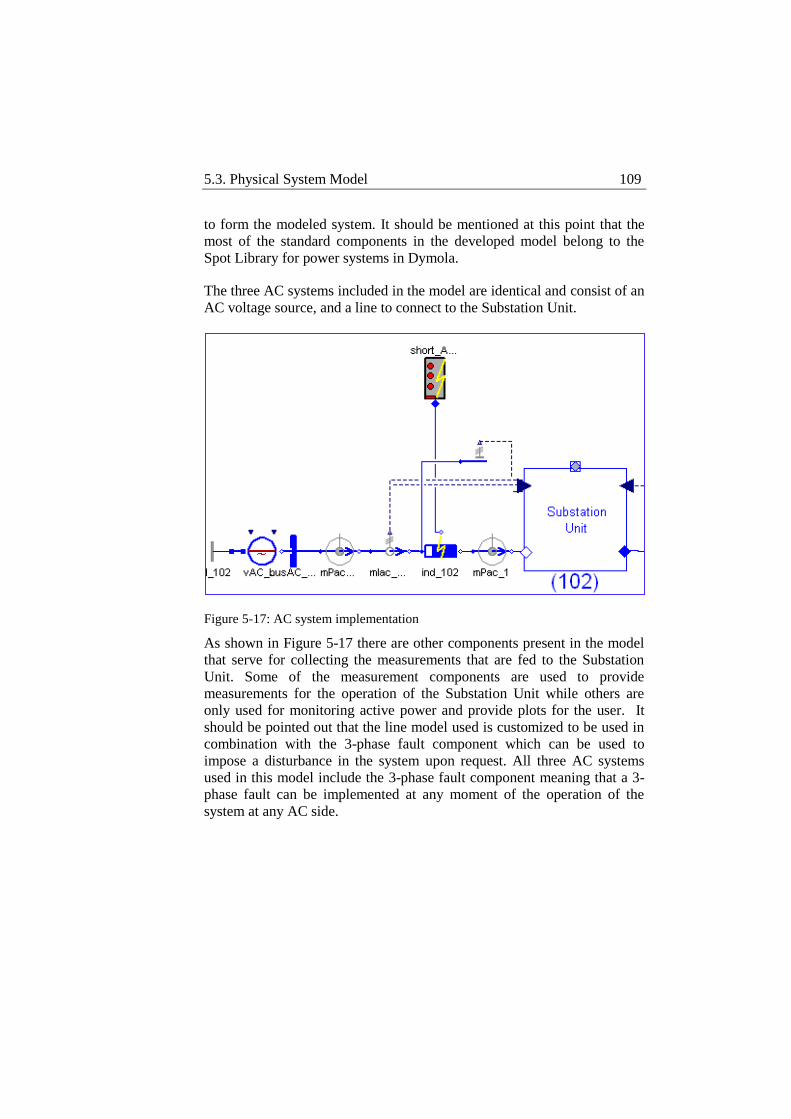
5.3. Physical System Model 109
to form the modeled system. It should be mentioned at this point that the
most of the standard components in the developed model belong to the
Spot Library for power systems in Dymola.
The three AC systems included in the model are identical and consist of an
AC voltage source, and a line to connect to the Substation Unit.
Figure 5-17: AC system implementation
As shown in Figure 5-17 there are other components present in the model
that serve for collecting the measurements that are fed to the Substation
Unit. Some of the measurement components are used to provide
measurements for the operation of the Substation Unit while others are
only used for monitoring active power and provide plots for the user. It
should be pointed out that the line model used is customized to be used in
combination with the 3-phase fault component which can be used to
impose a disturbance in the system upon request. All three AC systems
used in this model include the 3-phase fault component meaning that a 3-
phase fault can be implemented at any moment of the operation of the
system at any AC side.
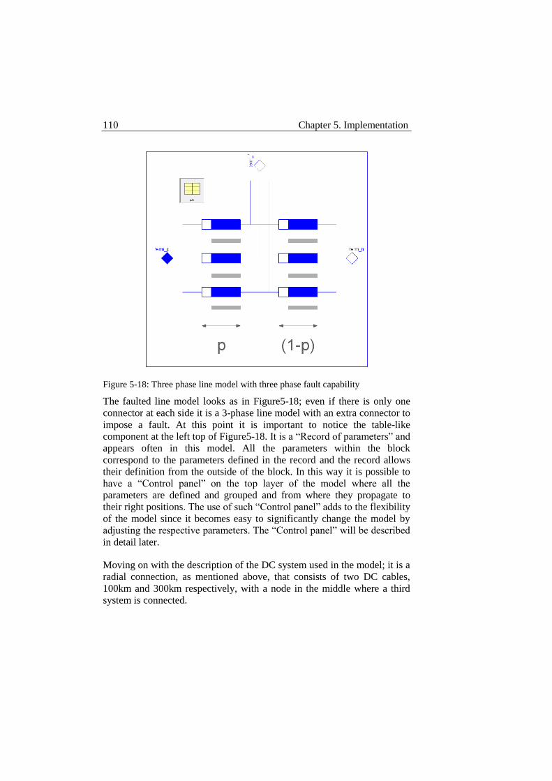
110 Chapter 5. Implementation
Figure 5-18: Three phase line model with three phase fault capability
The faulted line model looks as in Figure5-18; even if there is only one
connector at each side it is a 3-phase line model with an extra connector to
impose a fault. At this point it is important to notice the table-like
component at the left top of Figure5-18. It is a “Record of parameters” and
appears often in this model. All the parameters within the block
correspond to the parameters defined in the record and the record allows
their definition from the outside of the block. In this way it is possible to
have a “Control panel” on the top layer of the model where all the
parameters are defined and grouped and from where they propagate to
their right positions. The use of such “Control panel” adds to the flexibility
of the model since it becomes easy to significantly change the model by
adjusting the respective parameters. The “Control panel” will be described
in detail later.
Moving on with the description of the DC system used in the model; it is a
radial connection, as mentioned above, that consists of two DC cables,
100km and 300km respectively, with a node in the middle where a third
system is connected.
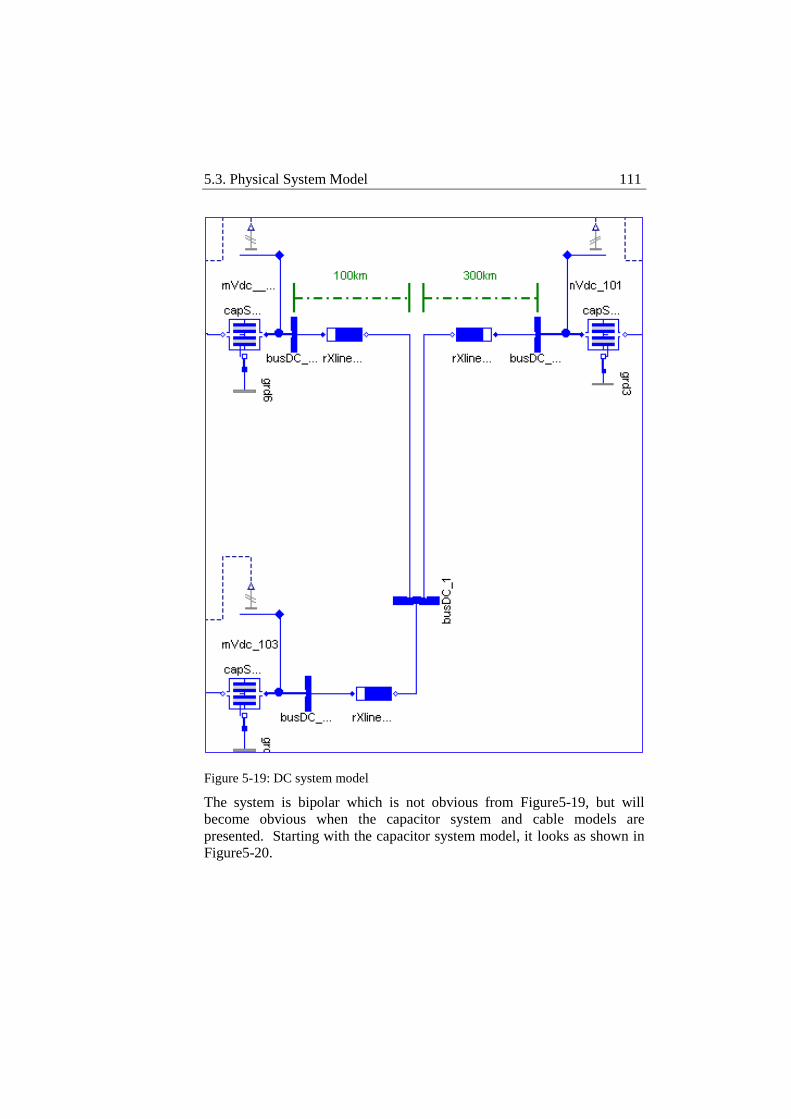
5.3. Physical System Model 111
Figure 5-19: DC system model
The system is bipolar which is not obvious from Figure5-19, but will
become obvious when the capacitor system and cable models are
presented. Starting with the capacitor system model, it looks as shown in
Figure5-20.
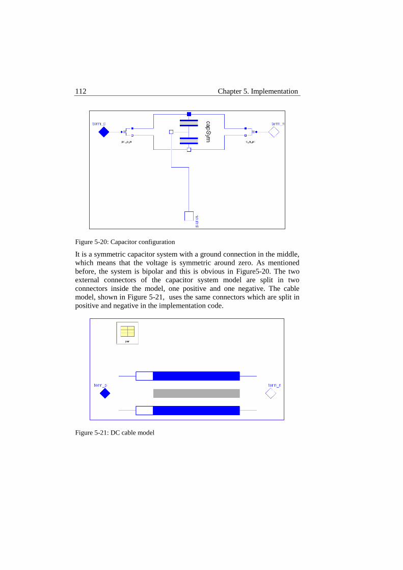
112 Chapter 5. Implementation
Figure 5-20: Capacitor configuration
It is a symmetric capacitor system with a ground connection in the middle,
which means that the voltage is symmetric around zero. As mentioned
before, the system is bipolar and this is obvious in Figure5-20. The two
external connectors of the capacitor system model are split in two
connectors inside the model, one positive and one negative. The cable
model, shown in Figure 5-21, uses the same connectors which are split in
positive and negative in the implementation code.
Figure 5-21: DC cable model
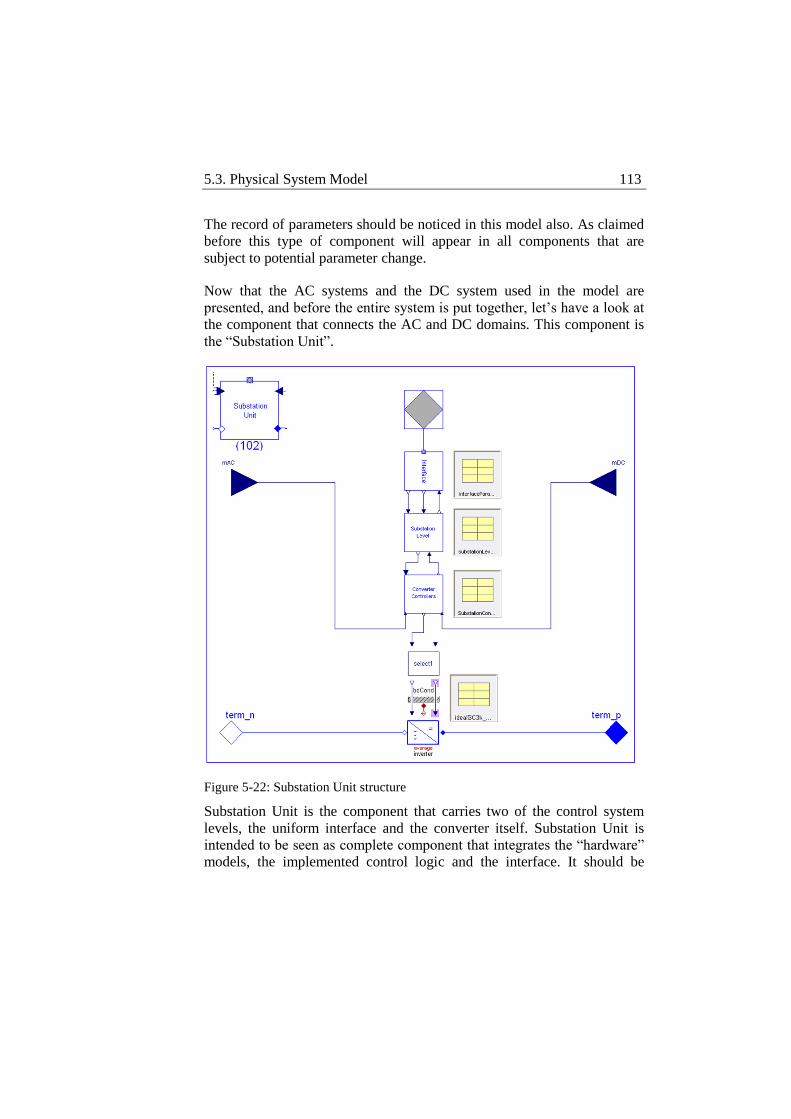
5.3. Physical System Model 113
The record of parameters should be noticed in this model also. As claimed
before this type of component will appear in all components that are
subject to potential parameter change.
Now that the AC systems and the DC system used in the model are
presented, and before the entire system is put together, let’s have a look at
the component that connects the AC and DC domains. This component is
the “Substation Unit”.
Figure 5-22: Substation Unit structure
Substation Unit is the component that carries two of the control system
levels, the uniform interface and the converter itself. Substation Unit is
intended to be seen as complete component that integrates the “hardware”
models, the implemented control logic and the interface. It should be
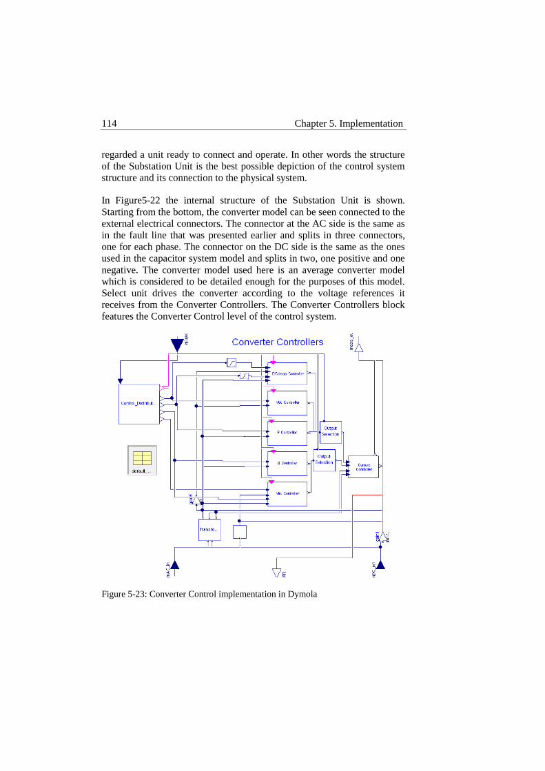
114 Chapter 5. Implementation
regarded a unit ready to connect and operate. In other words the structure
of the Substation Unit is the best possible depiction of the control system
structure and its connection to the physical system.
In Figure5-22 the internal structure of the Substation Unit is shown.
Starting from the bottom, the converter model can be seen connected to the
external electrical connectors. The connector at the AC side is the same as
in the fault line that was presented earlier and splits in three connectors,
one for each phase. The connector on the DC side is the same as the ones
used in the capacitor system model and splits in two, one positive and one
negative. The converter model used here is an average converter model
which is considered to be detailed enough for the purposes of this model.
Select unit drives the converter according to the voltage references it
receives from the Converter Controllers. The Converter Controllers block
features the Converter Control level of the control system.
Figure 5-23: Converter Control implementation in Dymola
5.3. Physical System Model 115
The Converter Controllers block, shown in Figure 5-23, contains the
controller set used to control the converter. Measurements from the outside
of the Substation unit end up in this block, where they are transformed to
the d-q frame and their per unit values are calculated. They are then used
by the different controllers and fed to the upper level. The Converter
Controllers block also receives the necessary control signals and setpoints
by the Substation Control level which go through the Control Distribution
block and are directed to the respective controllers. Enable signals prevent
non-operating PI controllers from integrating variables they do not control
saving simulation time in this way. All controllers send their output to the
Current Controller where the current reference is transformed to a voltage
reference to be sent to the Select unit and then to the converter. The
control implemented here is standard, it is performed in d-q frame and then
a cascade arrangement is used. Outer PI controllers operate on the
controlled variables to produce a current reference, the current reference is
then sent to the inner Current Controller to produce the voltage reference
required by the converter. The d-q frame allows decoupled control while
the controller set allows different combinations of control modes for the
substation. The used controller set contains a DC droop controller, a DC
voltage controller and an Active power controller for d axis and a Reactive
power controller and an AC voltage controller for the q axis.
Moving upwards, the Converter Controllers block communicates with the
Substation Control block. The Substation Control simply uses external
C++ functions which means that it is essentially implemented in C++ as
mentioned earlier. Substation Control block interprets the received control
signals for the Converter Controllers block and receives the measurements
obtained there to monitor the operation of the converter and create the
necessary error signals when necessary. It also sorts the information
received by the Converter Controllers block and places it in the interface
to be read by DC System Control. On its top side the Substation Control
block has two inputs and one output. The two inputs correspond to the
Operational and the Schedule Vectors which are the two ways DC System
Control can operate each substation and their functionality was explained
in Section 5.1. The output contains all the measurements that need to be
known to DC System Control. They are made available to DC System
Control by being placed in the uniform interface in the required order.
Substation Control also outputs in the uniform interface information
116 Chapter 5. Implementation
regarding errors and its control status that are useful for the coordination
operation performed by DC System Control.
Moving again upwards, the next block is the Uniform Interface. The
Uniform Interface is also implemented in C++, thus the Interface block in
Dymola simply calls external C++ functions. The functionality of the
Uniform interface is to provide a common interfacing pattern for the
different substations and tag each Operational-Schedule Vector set with
the user-defined identity of each substation. As mentioned in Section 5.1,
each substation receives an identity at initialization. This identity is
automatically generated in the C++ code and helps DC System Control to
address and operate the different terminals of the system. The
automatically generated identity though is not known to the user neither to
the incoming schedule. The user needs to define an identity for each
substation by which each substation is referred in the provided schedule.
This identity is defined in the configuration vector of the Uniform
Interface but is not related to the internal identity system. An internal
function in DC System Control corresponds then the user-defined identity
to the automatically generated identity within the C++ code. It is important
that the user does not have the right to interfere with the internal identity
system for double definitions to be avoided but it is also important that the
user has a way to refer to the different substations when necessary. The
Uniform Interface offers this possibility as an independent identity system
that is later used internally within DC System Control. Operational and
Schedule commands reach the output of the Uniform Interface and are
then sent to the Substation Control block while Operational feedback
reaches the interface from the Substation Control block and becomes then
available to DC System Control. Above the Interface block there is only
the connector to the DC System Control.
The intention is to present a complete Substation Unit that includes apart
from the converter, all which is necessary for its continuous control,
monitoring and interfacing with the overall control system. Thus, the
Substation Unit is an operation-ready unit needing only the electrical and
communications connection.
The records of parameters mentioned above are an indispensable feature
for the configuration of the Substation Unit. There is one record for each
block in the Substation Unit and the parameters defined in them range
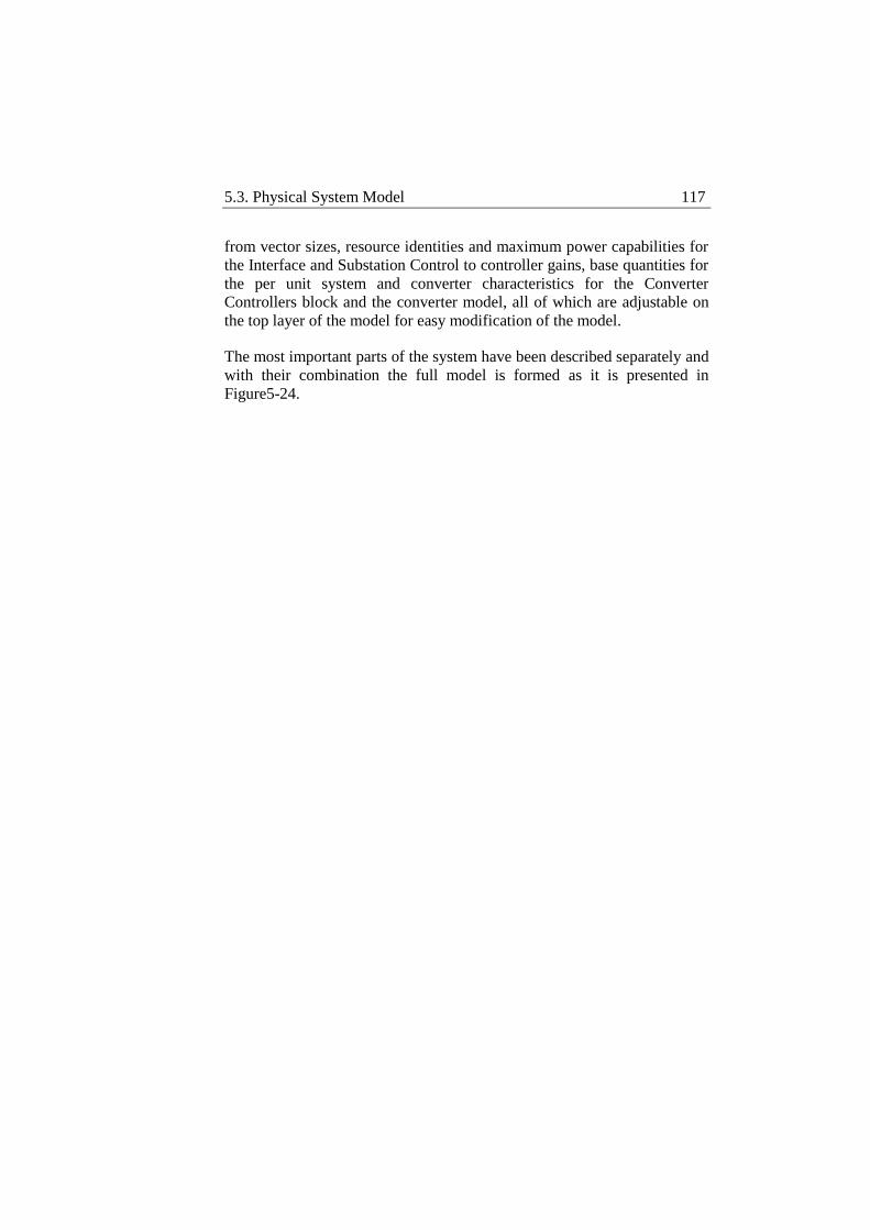
5.3. Physical System Model 117
from vector sizes, resource identities and maximum power capabilities for
the Interface and Substation Control to controller gains, base quantities for
the per unit system and converter characteristics for the Converter
Controllers block and the converter model, all of which are adjustable on
the top layer of the model for easy modification of the model.
The most important parts of the system have been described separately and
with their combination the full model is formed as it is presented in
Figure5-24.
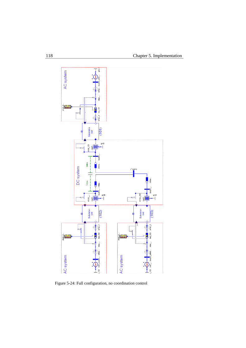
118 Chapter 5. Implementation
Figure 5-24: Full configuration, no coordination control
5.3. Physical System Model 119
Figure5-24 shows the model of the used 3-terminal VSC-HVDC system
but the overall control is not added yet. The system in this form contains
three operation-ready terminals and the components needed to create 3-
phase AC faults. To complete the coordinated 3-terminal system, DC
System Control needs to be added together with the necessary components
to create the communication loss events. The complete system appears in
Figure5-25.
DC System Control has been added in Figure5-25, together with the
necessary communication lines and the necessary components to create the
communication loss events upon request. DC System Control is
implemented in C++ as described in Section 5.1, thus the DC System
Control block operates on external C++ functions. It should be noticed that
DC System Control comes with an extra input and an extra output on the
side. These are to control the schedule input. The schedule is a table that
contains the scheduled power flows for the system, in terms of power
setpoints, voltage levels and control modes, divided in hours and each hour
is transferred to DC System Control upon request. The schedule is read by
DC System Control and distributed to the different terminals.
Now that the system is complete and able to perform all the previously
defined tests regarding power flows implementation, handling of
communication loss events and 3-phase AC faults, what remains to be
defined are the different parameters of the model. As mentioned above this
takes place on the top layer of the model with the help of the “Control
panel” which uses the functionality of records of parameters to propagate
the defined parameters to the right position, in the right layer of the model.
Control panel groups a number of records of parameters that each
corresponds to a specific component for each substation unit and its AC
line. Common parameters of the system like DC cable capacity and
converter settings are separate records and are used commonly. The
benefit that the Control panel offers is that different sets of parameters can
be saved and using the same model substantially different systems can be
tested simply by replacing the records in the Control panel.
120 Chapter 5. Implementation
Figure 5-25: Full configuration, DC System Control included
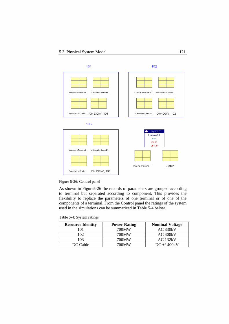
5.3. Physical System Model 121
Figure 5-26: Control panel
As shown in Figure5-26 the records of parameters are grouped according
to terminal but separated according to component. This provides the
flexibility to replace the parameters of one terminal or of one of the
components of a terminal. From the Control panel the ratings of the system
used in the simulations can be summarized in Table 5-4 below.
Table 5-4: System ratings
Resource Identity Power Rating Nominal Voltage
101 700MW AC 330kV
102 700MW AC 400kV
103 700MW AC 132kV
DC Cable 700MW DC +/-400kV

122 Chapter 5. Implementation
The model is now set up to provide all the functionality required to
examine the previously defined test objectives. In addition, special
consideration has been taken regarding the structure and flexibility of the
model in order to be reusable. The model is structured to be easily changed
to test different functionalities on different levels of detail.
Chapter 6 Simulation and Verification
Test objectives have been divided in two categories in the previous
section. From this division an inventory of two models occurred, each to
validate one category of test objectives. The two models were described in
detail in the previous section and since the tools are in place for test
objective validation, the simulation scenarios will be described in this
section, through which the models will validate the structural and
operational features of the system. The results of the simulations for each
of the two models will be presented and discussed in this section also.
6.1 Structural Features
Simulation Scenarios
As discussed in the previous section the structural test objectives are
related to the structural features of the proposed control system structure
and have to do first, with the correct propagation of control signals through
the different control levels and the uniform interfaces and second, with its
modularity and consequently its expandability. In this context, the
proposed control system will first be tested on a 3-terminal system during
a simple startup procedure to assure right propagation of control signals
and adequate coordination of the different terminals. Then, an additional
terminal will be added making the previous setup a 4-terminal system. The
additional terminal will be connected directly to the control system
through a uniform interface. This is to test the ability of the control system
to easily integrate new terminals. The control system is expected to
recognize and operate the new terminal without any change in its code.
This is an important feature and once validated it will show the modularity
of the system obtained by the common interfacing pattern defined by the
124 Chapter 6. Simulation and Verification
uniform interface and the flexibility of the overall control system to
identify the physical system and operate it accordingly.
Since the order of presentation of the test objectives follows the actual
timeline of development of this control system structure, it should be
mentioned that these tests took place early in the development of the
proposed control system structure and thus the contents of the different
control levels and the uniform interface are slightly different than their
final versions. The implementation differences are not important in the
different control levels for the validation of the structural features,
although it is important to mention the difference in the uniform interface
data set to be possible to follow the results later on. The uniform interface
data set was described in Section 5.1 in Table 5-1 and Table 5-2. Table 5-1
presents the Operational Vector signal configuration and Table 5-2
presents the Schedule Vector signal configuration. As described in Section
5.1, the Operational Vector is used by DC System Control during off-
normal operation, while the Schedule Vector is used during normal
operation. Since in this case the control system will only be tested for a
startup procedure, the Schedule Vector will not be used and thus is not
included in the uniform interface. The signal configuration for the
Operational Vector is also different to correspond to the different model.
Since the converters of this model are DC/DC converters the control
direction must be defined. Table 6-1 presents the full signal configuration
of the Operational Vector for this model.
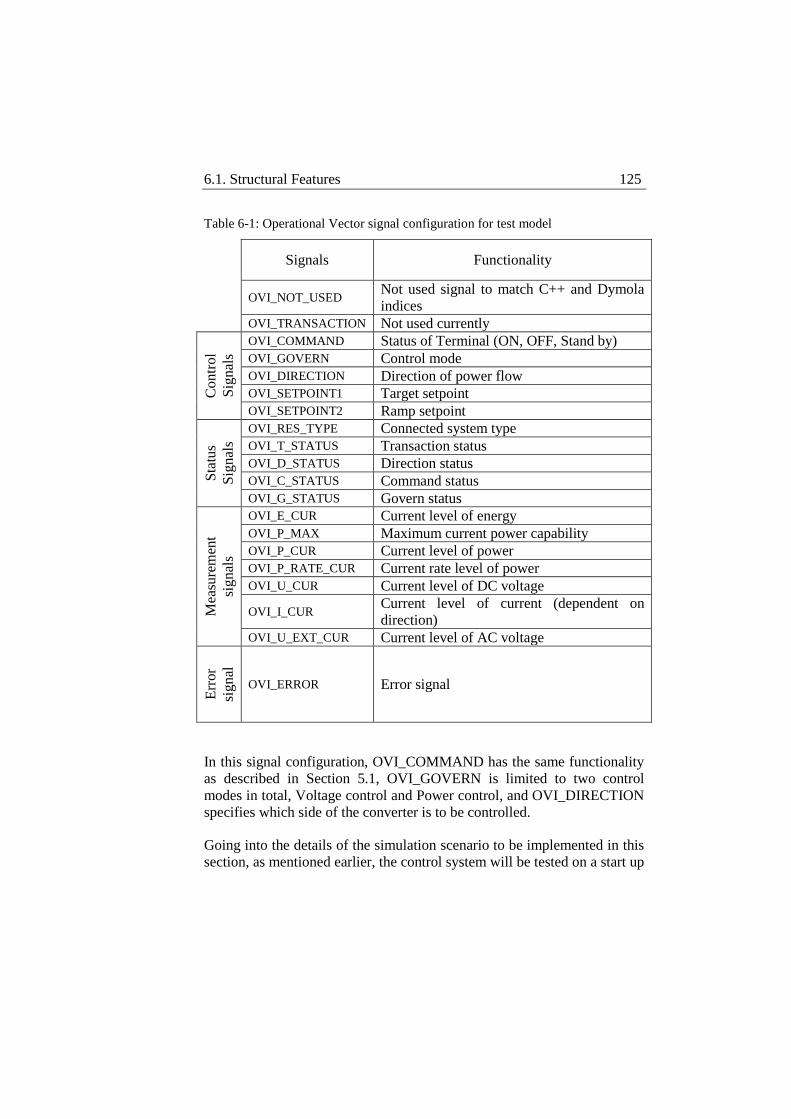
6.1. Structural Features 125
Table 6-1: Operational Vector signal configuration for test model
Signals Functionality
OVI_NOT_USED
Not used signal to match C++ and Dymola
indices
OVI_TRANSACTION Not used currently
Co
ntr
ol
Sig
nal
s
OVI_COMMAND Status of Terminal (ON, OFF, Stand by)
OVI_GOVERN Control mode
OVI_DIRECTION Direction of power flow
OVI_SETPOINT1 Target setpoint
OVI_SETPOINT2 Ramp setpoint
Sta
tus
Sig
nal
s
OVI_RES_TYPE Connected system type
OVI_T_STATUS Transaction status
OVI_D_STATUS Direction status
OVI_C_STATUS Command status
OVI_G_STATUS Govern status
Mea
sure
men
t
signal
s
OVI_E_CUR Current level of energy
OVI_P_MAX Maximum current power capability
OVI_P_CUR Current level of power
OVI_P_RATE_CUR Current rate level of power
OVI_U_CUR Current level of DC voltage
OVI_I_CUR Current level of current (dependent on
direction)
OVI_U_EXT_CUR Current level of AC voltage
Err
or
signal
OVI_ERROR Error signal
In this signal configuration, OVI_COMMAND has the same functionality
as described in Section 5.1, OVI_GOVERN is limited to two control
modes in total, Voltage control and Power control, and OVI_DIRECTION
specifies which side of the converter is to be controlled.
Going into the details of the simulation scenario to be implemented in this
section, as mentioned earlier, the control system will be tested on a start up
126 Chapter 6. Simulation and Verification
procedure for a 3-terminal system in the beginning. The control system is
expected to go through the different states of its state machine until the DC
link is charged. This includes the initialization of the system, the selection
of one terminal to charge the DC link and the advance to the normal
operation state when the DC link is charged. During initialization the
different objects are created in the control system and then classified in the
Module Manager according to their corresponding class and their place in
hierarchy. Their configuration vectors are also read by the DC System
Control where information regarding their type, external id and maximum
power capacity is included. At the same time their Operational Vectors are
created and one is corresponded to each SCO. When the different objects
in the system are initialized, an availability check takes place and all error
free terminals are set to READY (stand-by mode) and sorted in generating,
consuming or exchange terminals. This happens so that DC System
Control can make the selection of the terminal that will be given the duty
to charge the DC link. In this implementation the generating or exchange
terminal with the highest power capacity is selected to charge the DC link.
It is expected then, that DC System Control will go through the different
states until the DC link is charged. During this process the generating or
exchange terminal of highest capacity will be set to START on Voltage
control to charge the DC link while the rest of the terminals will remain at
stand-by (READY). When the DC link is charged DC System Control
proceeds to normal operation state and the rest of the terminals are set to
START to begin normal operation. This test will validate the correct
circulation of data among the different control levels since control signals
generated in the DC System Control must reach the converters to perform
the charging operation while measurements obtained in the Converter
Control level must reach the DC System Control level which will monitor
them to decide the transitions between its different states.
In the second part of the simulations for structural features validation, the
same operation takes place but this time an additional terminal is added to
expand the previous system to a 4-terminal system. The stages of
operation of DC System Control are the same as for the previous case. The
intention here is to test the ability of DC System Control to integrate in its
operation an additional terminal without any modification in its
implementation code. The additional terminal is connected through the
uniform interface directly to the communication node where the rest of the
existing terminals are connected. The newly added terminal is
6.1. Structural Features 127
intentionally defined as the exchange terminal, bi-directional power flow
capable, with the highest power capacity so that it is given an active role in
charging the DC link by DC System Control. The desirable outcome of
this simulation is that the additional terminal is identified and operated by
DC System Control directly. This result will validate the role of the
uniform interface in providing a modular interfacing system that allows
the expansion of the system, on one hand. On the other hand, it will
validate the general nature of DC System Control and its ability to operate
different numbers of terminals without being limited by their type or
external, user-defined, identities.
Results
Since the focus for this set of simulations is to validate the correct
circulation of data, the ratings of the system are insignificant and thus very
low. The target DC voltage is only 100V and the focus is on the different
states the system goes through to reach it. Figure 6-1 shows the 3-terminal
system used for this simulation together with the identity of each terminal
(rIDs). Before discussing the results of the simulation it is useful to
provide an explanation for the signals that appear. The different states of
DC System Control are presented together with the command and govern
signals distributed to the different terminals according to the state DC
System Control is in. The meaning of these signals has been discussed in
previous sections and only the numbering is provided at this point in Table
6-2.
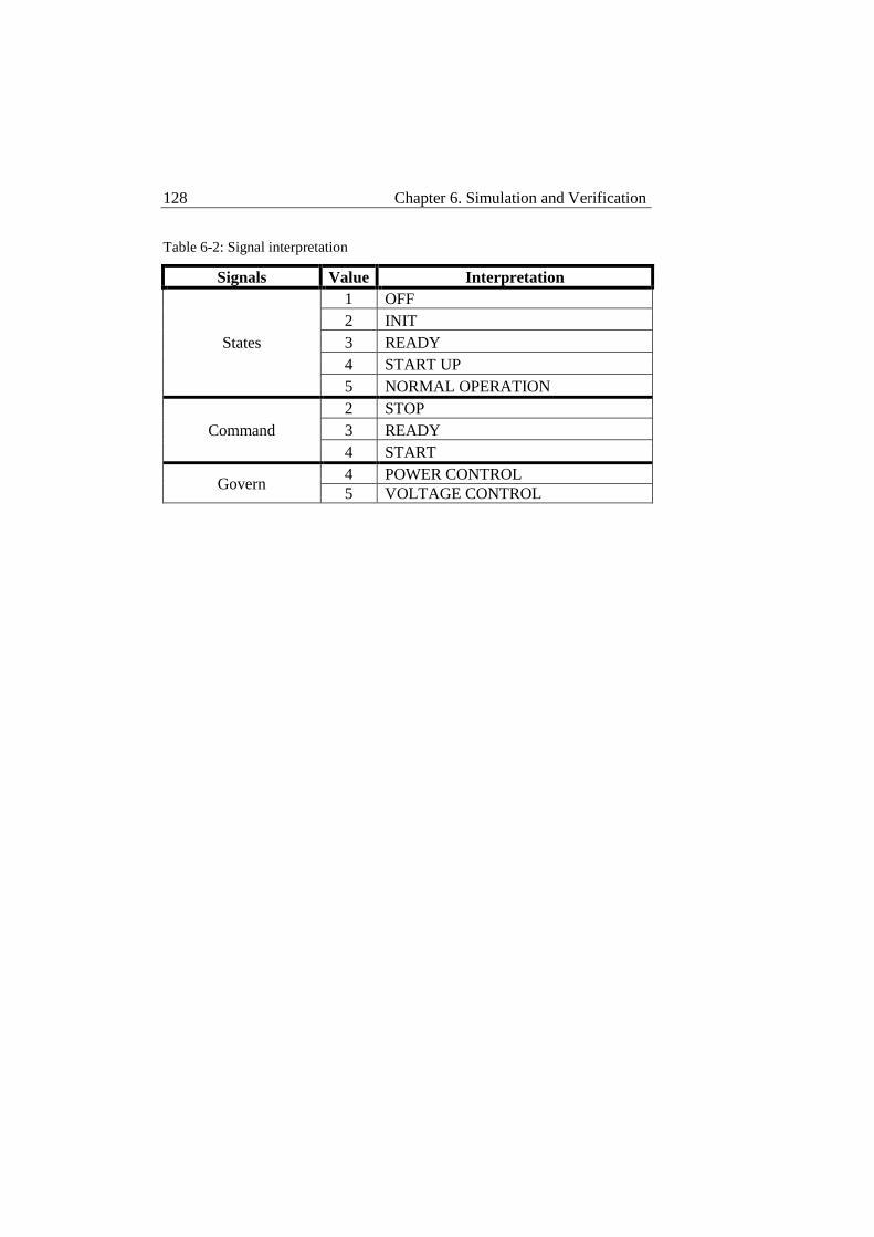
128 Chapter 6. Simulation and Verification
Table 6-2: Signal interpretation
Signals Value Interpretation
States
1 OFF
2 INIT
3 READY
4 START UP
5 NORMAL OPERATION
Command
2 STOP
3 READY
4 START
Govern 4 POWER CONTROL
5 VOLTAGE CONTROL
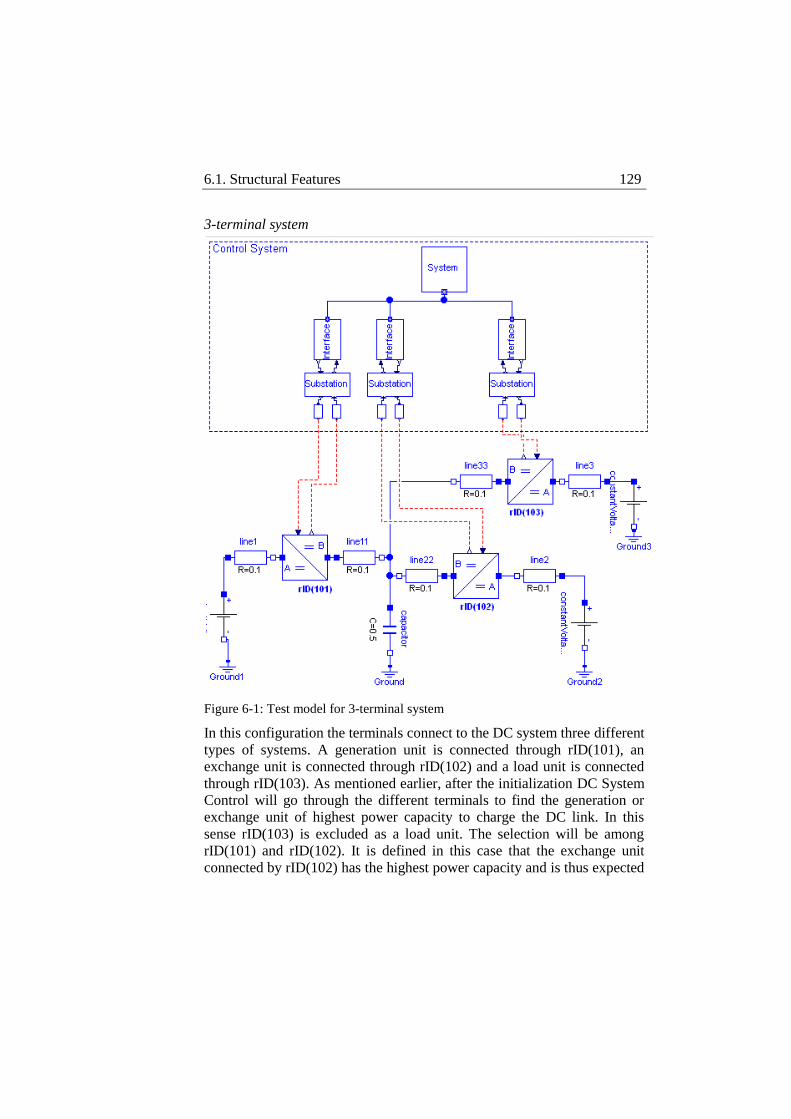
6.1. Structural Features 129
3-terminal system
Figure 6-1: Test model for 3-terminal system
In this configuration the terminals connect to the DC system three different
types of systems. A generation unit is connected through rID(101), an
exchange unit is connected through rID(102) and a load unit is connected
through rID(103). As mentioned earlier, after the initialization DC System
Control will go through the different terminals to find the generation or
exchange unit of highest power capacity to charge the DC link. In this
sense rID(103) is excluded as a load unit. The selection will be among
rID(101) and rID(102). It is defined in this case that the exchange unit
connected by rID(102) has the highest power capacity and is thus expected
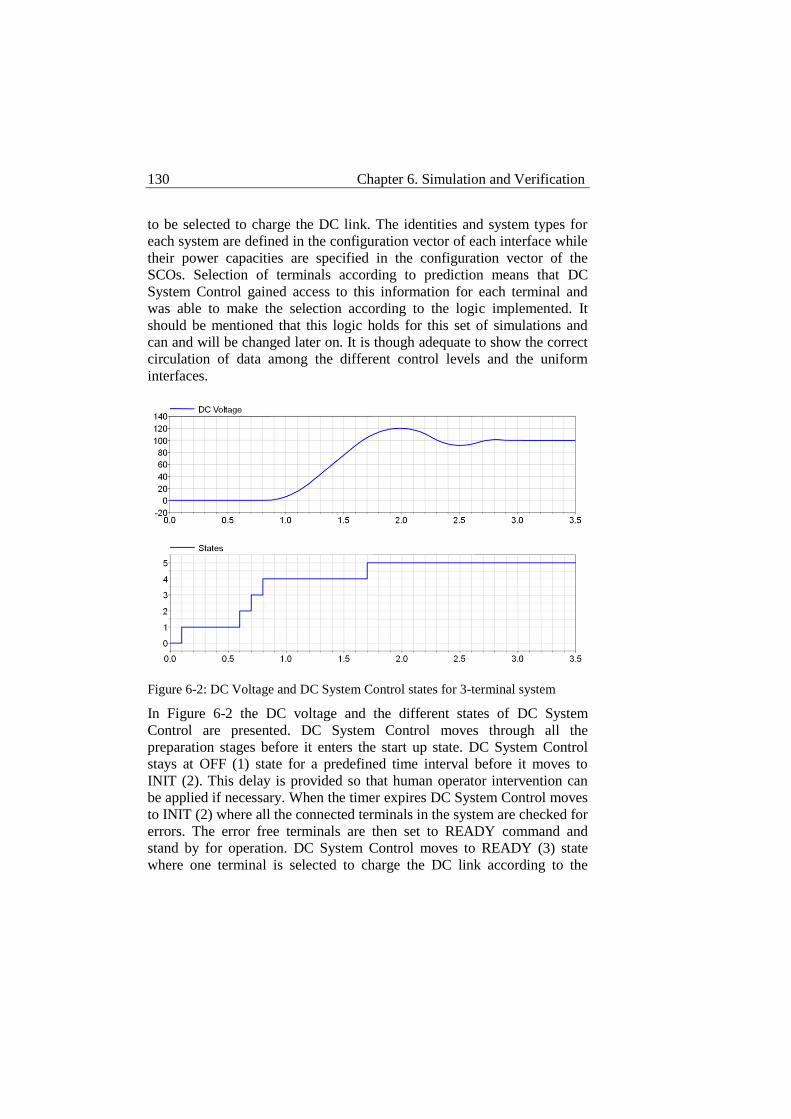
130 Chapter 6. Simulation and Verification
to be selected to charge the DC link. The identities and system types for
each system are defined in the configuration vector of each interface while
their power capacities are specified in the configuration vector of the
SCOs. Selection of terminals according to prediction means that DC
System Control gained access to this information for each terminal and
was able to make the selection according to the logic implemented. It
should be mentioned that this logic holds for this set of simulations and
can and will be changed later on. It is though adequate to show the correct
circulation of data among the different control levels and the uniform
interfaces.
Figure 6-2: DC Voltage and DC System Control states for 3-terminal system
In Figure 6-2 the DC voltage and the different states of DC System
Control are presented. DC System Control moves through all the
preparation stages before it enters the start up state. DC System Control
stays at OFF (1) state for a predefined time interval before it moves to
INIT (2). This delay is provided so that human operator intervention can
be applied if necessary. When the timer expires DC System Control moves
to INIT (2) where all the connected terminals in the system are checked for
errors. The error free terminals are then set to READY command and
stand by for operation. DC System Control moves to READY (3) state
where one terminal is selected to charge the DC link according to the
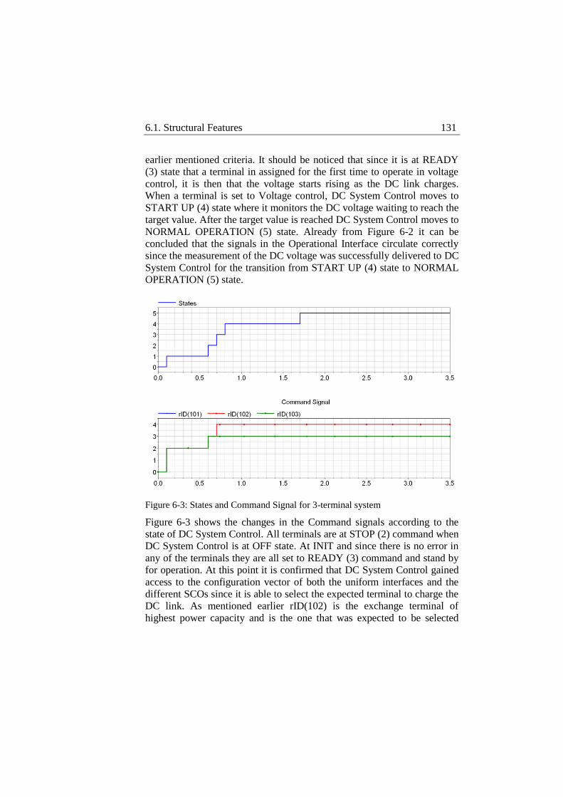
6.1. Structural Features 131
earlier mentioned criteria. It should be noticed that since it is at READY
(3) state that a terminal in assigned for the first time to operate in voltage
control, it is then that the voltage starts rising as the DC link charges.
When a terminal is set to Voltage control, DC System Control moves to
START UP (4) state where it monitors the DC voltage waiting to reach the
target value. After the target value is reached DC System Control moves to
NORMAL OPERATION (5) state. Already from Figure 6-2 it can be
concluded that the signals in the Operational Interface circulate correctly
since the measurement of the DC voltage was successfully delivered to DC
System Control for the transition from START UP (4) state to NORMAL
OPERATION (5) state.
Figure 6-3: States and Command Signal for 3-terminal system
Figure 6-3 shows the changes in the Command signals according to the
state of DC System Control. All terminals are at STOP (2) command when
DC System Control is at OFF state. At INIT and since there is no error in
any of the terminals they are all set to READY (3) command and stand by
for operation. At this point it is confirmed that DC System Control gained
access to the configuration vector of both the uniform interfaces and the
different SCOs since it is able to select the expected terminal to charge the
DC link. As mentioned earlier rID(102) is the exchange terminal of
highest power capacity and is the one that was expected to be selected
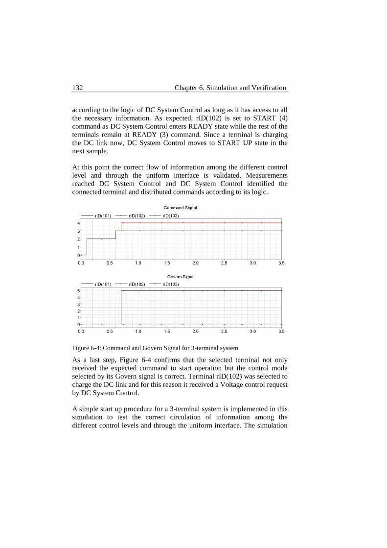
132 Chapter 6. Simulation and Verification
according to the logic of DC System Control as long as it has access to all
the necessary information. As expected, rID(102) is set to START (4)
command as DC System Control enters READY state while the rest of the
terminals remain at READY (3) command. Since a terminal is charging
the DC link now, DC System Control moves to START UP state in the
next sample.
At this point the correct flow of information among the different control
level and through the uniform interface is validated. Measurements
reached DC System Control and DC System Control identified the
connected terminal and distributed commands according to its logic.
Figure 6-4: Command and Govern Signal for 3-terminal system
As a last step, Figure 6-4 confirms that the selected terminal not only
received the expected command to start operation but the control mode
selected by its Govern signal is correct. Terminal rID(102) was selected to
charge the DC link and for this reason it received a Voltage control request
by DC System Control.
A simple start up procedure for a 3-terminal system is implemented in this
simulation to test the correct circulation of information among the
different control levels and through the uniform interface. The simulation
6.1. Structural Features 133
results confirm the correct exchange of data among the DC System
Control and the different SCOs through the uniform interface. DC System
Control is able to identify the system that consists of different types of
connected systems, prepare and coordinate the operation of the different
terminals to perform the operation of charging the DC link. This is
possible due to the use of the uniform interface that defines a common
interfacing pattern between the different terminals and DC System Control
and due to the flexibility of DC System Control to handle terminals
according to their properties and without referring to a specific system
arrangement.
4-terminal system
So far, the correct circulation of data across the different levels of the
control system is validated. It is now time to test the ability of DC System
Control to incorporate and operate additional terminals without
modification in its code. To do so, an additional terminal is added to the
existing system and the same simple start up procedure is followed. No
modification in the code of DC System Control is made since the new
terminal is connected to DC System Control via the uniform interface.
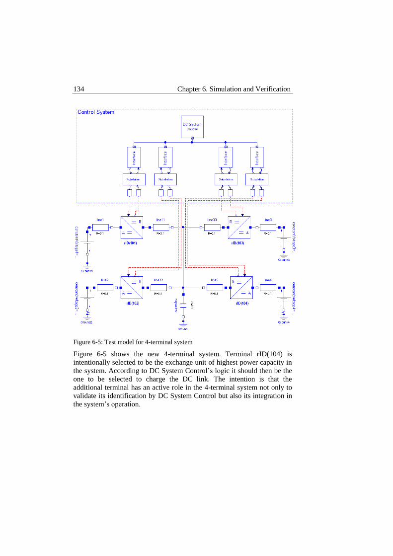
134 Chapter 6. Simulation and Verification
Figure 6-5: Test model for 4-terminal system
Figure 6-5 shows the new 4-terminal system. Terminal rID(104) is
intentionally selected to be the exchange unit of highest power capacity in
the system. According to DC System Control’s logic it should then be the
one to be selected to charge the DC link. The intention is that the
additional terminal has an active role in the 4-terminal system not only to
validate its identification by DC System Control but also its integration in
the system’s operation.
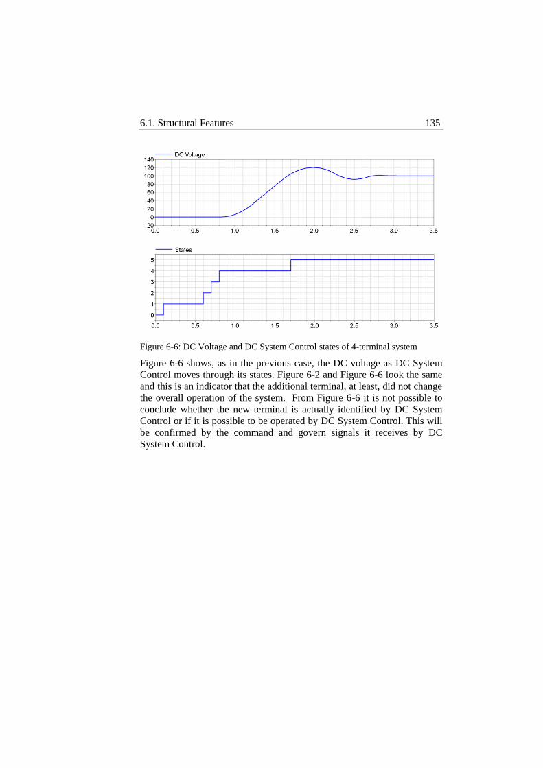
6.1. Structural Features 135
Figure 6-6: DC Voltage and DC System Control states of 4-terminal system
Figure 6-6 shows, as in the previous case, the DC voltage as DC System
Control moves through its states. Figure 6-2 and Figure 6-6 look the same
and this is an indicator that the additional terminal, at least, did not change
the overall operation of the system. From Figure 6-6 it is not possible to
conclude whether the new terminal is actually identified by DC System
Control or if it is possible to be operated by DC System Control. This will
be confirmed by the command and govern signals it receives by DC
System Control.
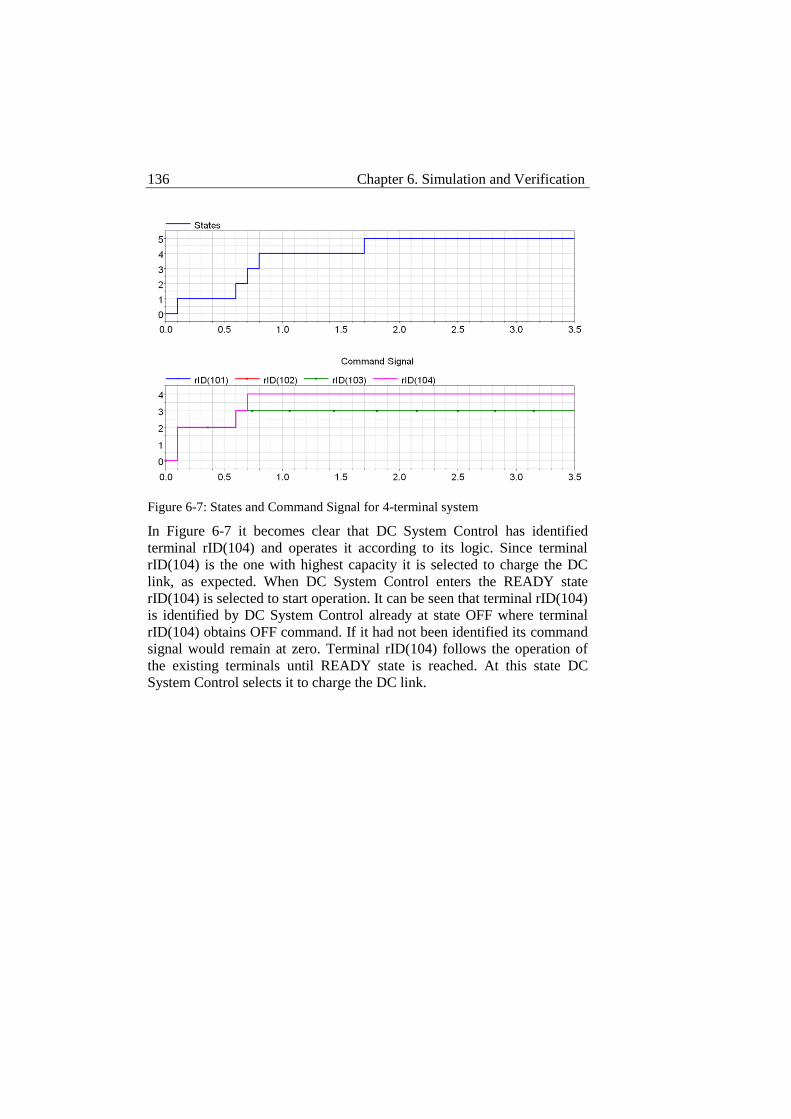
136 Chapter 6. Simulation and Verification
Figure 6-7: States and Command Signal for 4-terminal system
In Figure 6-7 it becomes clear that DC System Control has identified
terminal rID(104) and operates it according to its logic. Since terminal
rID(104) is the one with highest capacity it is selected to charge the DC
link, as expected. When DC System Control enters the READY state
rID(104) is selected to start operation. It can be seen that terminal rID(104)
is identified by DC System Control already at state OFF where terminal
rID(104) obtains OFF command. If it had not been identified its command
signal would remain at zero. Terminal rID(104) follows the operation of
the existing terminals until READY state is reached. At this state DC
System Control selects it to charge the DC link.
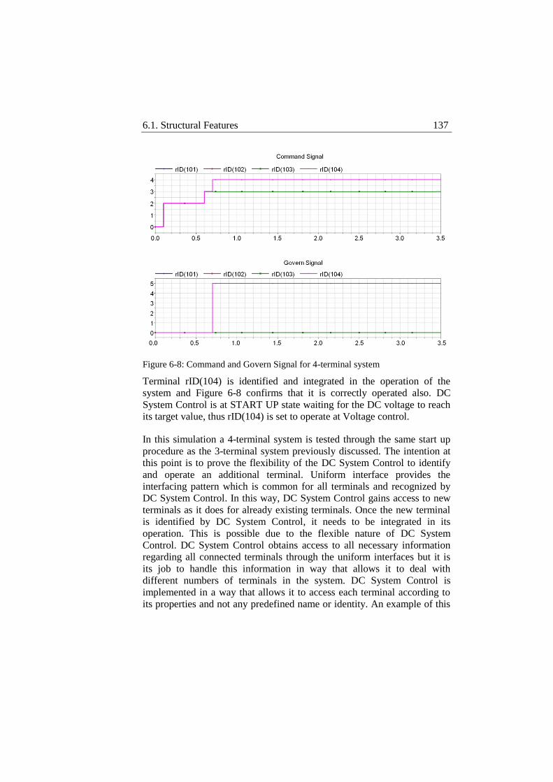
6.1. Structural Features 137
Figure 6-8: Command and Govern Signal for 4-terminal system
Terminal rID(104) is identified and integrated in the operation of the
system and Figure 6-8 confirms that it is correctly operated also. DC
System Control is at START UP state waiting for the DC voltage to reach
its target value, thus rID(104) is set to operate at Voltage control.
In this simulation a 4-terminal system is tested through the same start up
procedure as the 3-terminal system previously discussed. The intention at
this point is to prove the flexibility of the DC System Control to identify
and operate an additional terminal. Uniform interface provides the
interfacing pattern which is common for all terminals and recognized by
DC System Control. In this way, DC System Control gains access to new
terminals as it does for already existing terminals. Once the new terminal
is identified by DC System Control, it needs to be integrated in its
operation. This is possible due to the flexible nature of DC System
Control. DC System Control obtains access to all necessary information
regarding all connected terminals through the uniform interfaces but it is
its job to handle this information in way that allows it to deal with
different numbers of terminals in the system. DC System Control is
implemented in a way that allows it to access each terminal according to
its properties and not any predefined name or identity. An example of this
138 Chapter 6. Simulation and Verification
is the selection of the terminal to charge the DC link. DC System Control
will search and find the terminal with highest capacity among the
generating or exchange terminals. The number of terminals in the search is
irrelevant, thus newly connected terminals can be part of it.
The set of tests in this section confirmed the structural features of the
proposed control system. Circulation of data is essential especially for an
abstract control system structure where objects can be added virtually at
any time. The identity system implemented through Resource Manager
keeps track of the direction of data and the access rights of each object
while the uniform interface provides a common interfacing pattern so that
DC System Control is released from interfacing concerns with each
individual terminal and can focus on managing their properties. Simulation
results show that data travelling upwards or downwards in the hierarchy of
the control system successfully finds its target and makes the identification
and coordination of the system possible. The use of the uniform interface
in combination with the flexible implementation of DC System Control
allows new terminals to be easily integrated in the operation of the system.
The uniform interface assures that the additional terminal is identified by
DC System Control and takes responsibility of its interfacing with it. Then,
DC System Control handles the connected terminals, existing or new, in a
general way addressing them according to their properties and regardless
of external identities or names. In this way the additional terminal is not
only identified by DC System Control but also integrated in its operation
automatically.
6.2 Operational Features
Simulation Scenarios
In this set of simulations the operational features of the proposed control
system are to be validated. As mentioned in Section 5.2, the operational
features are related to the adequate implementation of requested power
flows according to a schedule. Since in this case the focus is on the
accurate implementation of the requested power flows, the verification
model is necessary to follow closely power and voltage levels in the
system. The proposed control system is implemented at its final form, with
all its control levels and the uniform interface implemented as described in
Section 5.1. The model used is the one depicted in Figure 5.23.
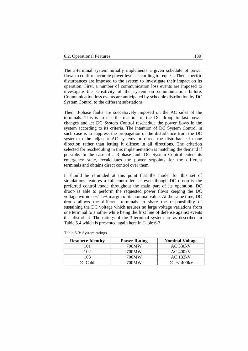
6.2. Operational Features 139
The 3-terminal system initially implements a given schedule of power
flows to confirm accurate power levels according to request. Then, specific
disturbances are imposed to the system to investigate their impact on its
operation. First, a number of communication loss events are imposed to
investigate the sensitivity of the system on communication failure.
Communication loss events are anticipated by schedule distribution by DC
System Control to the different substations
Then, 3-phase faults are successively imposed on the AC sides of the
terminals. This is to test the reaction of the DC droop to fast power
changes and let DC System Control reschedule the power flows in the
system according to its criteria. The intention of DC System Control in
such case is to suppress the propagation of the disturbance from the DC
system to the adjacent AC systems or direct the disturbance in one
direction rather than letting it diffuse in all directions. The criterion
selected for rescheduling in this implementation is matching the demand if
possible. In the case of a 3-phase fault DC System Control enters its
emergency state, recalculates the power setpoints for the different
terminals and obtains direct control over them.
It should be reminded at this point that the model for this set of
simulations features a full controller set even though DC droop is the
preferred control mode throughout the main part of its operation. DC
droop is able to perform the requested power flows keeping the DC
voltage within a +/- 5% margin of its nominal value. At the same time, DC
droop allows the different terminals to share the responsibility of
sustaining the DC voltage which assures no large voltage variations from
one terminal to another while being the first line of defense against events
that disturb it. The ratings of the 3-terminal system are as described in
Table 5.4 which is presented again here in Table 6-3.
Table 6-3: System ratings
Resource Identity Power Rating Nominal Voltage
101 700MW AC 330kV
102 700MW AC 400kV
103 700MW AC 132kV
DC Cable 700MW DC +/-400kV
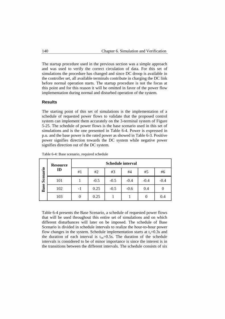
140 Chapter 6. Simulation and Verification
The startup procedure used in the previous section was a simple approach
and was used to verify the correct circulation of data. For this set of
simulations the procedure has changed and since DC droop is available in
the controller set, all available terminals contribute in charging the DC link
before normal operation starts. The startup procedure is not the focus at
this point and for this reason it will be omitted in favor of the power flow
implementation during normal and disturbed operation of the system.
Results
The starting point of this set of simulations is the implementation of a
schedule of requested power flows to validate that the proposed control
system can implement them accurately on the 3-terminal system of Figure
5-25. The schedule of power flows is the base scenario used in this set of
simulations and is the one presented in Table 6-4. Power is expressed in
p.u. and the base power is the rated power as showed in Table 6-3. Positive
power signifies direction towards the DC system while negative power
signifies direction out of the DC system.
Table 6-4: Base scenario, required schedule
Base
Sce
nari
o Resource
ID
Schedule interval
#1 #2 #3 #4 #5 #6
101 1 -0.5 -0.5 -0.4 -0.4 -0.4
102 -1 0.25 -0.5 -0.6 0.4 0
103 0 0.25 1 1 0 0.4
Table 6-4 presents the Base Scenario, a schedule of requested power flows
that will be used throughout this entire set of simulations and on which
different disturbances will later on be imposed. The schedule of Base
Scenario is divided in schedule intervals to realize the hour-to-hour power
flow changes in the system. Schedule implementation starts at ts=0.3s and
the duration of each interval is tint=0.5s. The duration of the schedule
intervals is considered to be of minor importance is since the interest is in
the transitions between the different intervals. The schedule consists of six
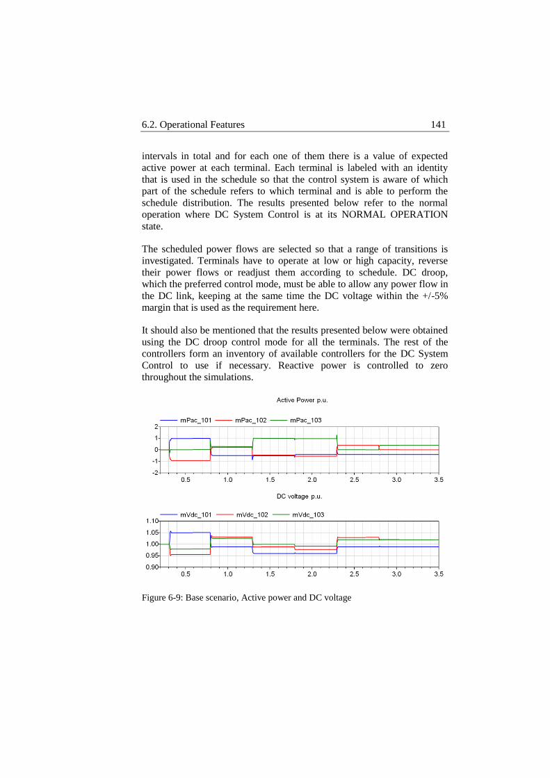
6.2. Operational Features 141
intervals in total and for each one of them there is a value of expected
active power at each terminal. Each terminal is labeled with an identity
that is used in the schedule so that the control system is aware of which
part of the schedule refers to which terminal and is able to perform the
schedule distribution. The results presented below refer to the normal
operation where DC System Control is at its NORMAL OPERATION
state.
The scheduled power flows are selected so that a range of transitions is
investigated. Terminals have to operate at low or high capacity, reverse
their power flows or readjust them according to schedule. DC droop,
which the preferred control mode, must be able to allow any power flow in
the DC link, keeping at the same time the DC voltage within the +/-5%
margin that is used as the requirement here.
It should also be mentioned that the results presented below were obtained
using the DC droop control mode for all the terminals. The rest of the
controllers form an inventory of available controllers for the DC System
Control to use if necessary. Reactive power is controlled to zero
throughout the simulations.
Figure 6-9: Base scenario, Active power and DC voltage
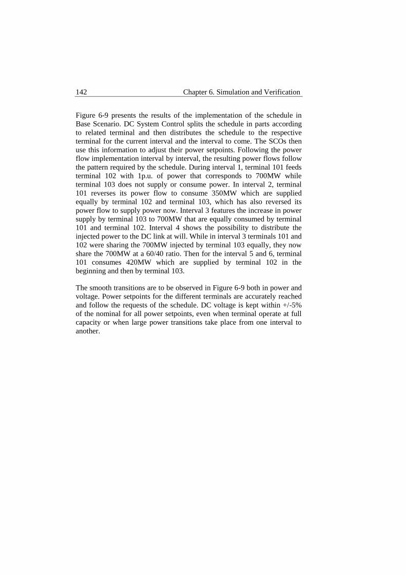
142 Chapter 6. Simulation and Verification
Figure 6-9 presents the results of the implementation of the schedule in
Base Scenario. DC System Control splits the schedule in parts according
to related terminal and then distributes the schedule to the respective
terminal for the current interval and the interval to come. The SCOs then
use this information to adjust their power setpoints. Following the power
flow implementation interval by interval, the resulting power flows follow
the pattern required by the schedule. During interval 1, terminal 101 feeds
terminal 102 with 1p.u. of power that corresponds to 700MW while
terminal 103 does not supply or consume power. In interval 2, terminal
101 reverses its power flow to consume 350MW which are supplied
equally by terminal 102 and terminal 103, which has also reversed its
power flow to supply power now. Interval 3 features the increase in power
supply by terminal 103 to 700MW that are equally consumed by terminal
101 and terminal 102. Interval 4 shows the possibility to distribute the
injected power to the DC link at will. While in interval 3 terminals 101 and
102 were sharing the 700MW injected by terminal 103 equally, they now
share the 700MW at a 60/40 ratio. Then for the interval 5 and 6, terminal
101 consumes 420MW which are supplied by terminal 102 in the
beginning and then by terminal 103.
The smooth transitions are to be observed in Figure 6-9 both in power and
voltage. Power setpoints for the different terminals are accurately reached
and follow the requests of the schedule. DC voltage is kept within +/-5%
of the nominal for all power setpoints, even when terminal operate at full
capacity or when large power transitions take place from one interval to
another.

6.2. Operational Features 143
Figure 6-10: Base scenario, DC droop controller detail
In Figure 6-10 the operation of one of the DC droop controller is
displayed. The measured signal follows closely the reference and this is
clearer at the zoomed detail.
Table 6-5: Single communication loss event during schedule
Sce
nari
o 1
Resource ID
Schedule interval
#1 #2 #3 #4 #5 #6
101 1 -0.5 -0.5 -0.4 -0.4 -0.4
102 -1 0.25 -0.5 -0.6 0.4 0
103 0 0.25 1 1 0 0.4
Table 6-5 shows Scenario 1, during which the same schedule as in Base
Scenario is implemented but a communication loss event happens during a
part of interval 1 and 2 for terminal 101. Scenario 1 intends to investigate
the behaviour of the system when communication is lost for a time period
with one of the terminals in the system. It should be reminded at this point
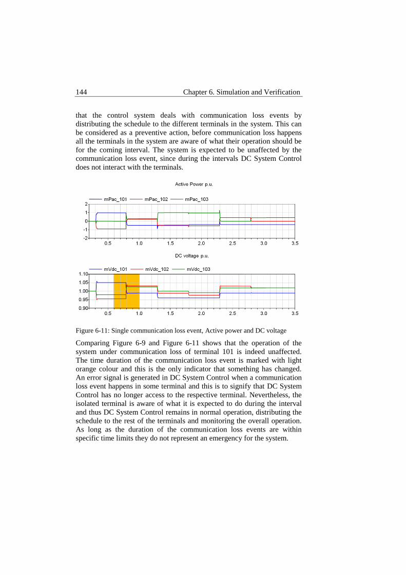
144 Chapter 6. Simulation and Verification
that the control system deals with communication loss events by
distributing the schedule to the different terminals in the system. This can
be considered as a preventive action, before communication loss happens
all the terminals in the system are aware of what their operation should be
for the coming interval. The system is expected to be unaffected by the
communication loss event, since during the intervals DC System Control
does not interact with the terminals.
Figure 6-11: Single communication loss event, Active power and DC voltage
Comparing Figure 6-9 and Figure 6-11 shows that the operation of the
system under communication loss of terminal 101 is indeed unaffected.
The time duration of the communication loss event is marked with light
orange colour and this is the only indicator that something has changed.
An error signal is generated in DC System Control when a communication
loss event happens in some terminal and this is to signify that DC System
Control has no longer access to the respective terminal. Nevertheless, the
isolated terminal is aware of what it is expected to do during the interval
and thus DC System Control remains in normal operation, distributing the
schedule to the rest of the terminals and monitoring the overall operation.
As long as the duration of the communication loss events are within
specific time limits they do not represent an emergency for the system.
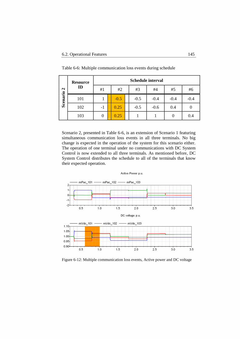
6.2. Operational Features 145
Table 6-6: Multiple communication loss events during schedule S
cen
ari
o 2
Resource ID
Schedule interval
#1 #2 #3 #4 #5 #6
101 1 -0.5 -0.5 -0.4 -0.4 -0.4
102 -1 0.25 -0.5 -0.6 0.4 0
103 0 0.25 1 1 0 0.4
Scenario 2, presented in Table 6-6, is an extension of Scenario 1 featuring
simultaneous communication loss events in all three terminals. No big
change is expected in the operation of the system for this scenario either.
The operation of one terminal under no communications with DC System
Control is now extended to all three terminals. As mentioned before, DC
System Control distributes the schedule to all of the terminals that know
their expected operation.
Figure 6-12: Multiple communication loss events, Active power and DC voltage
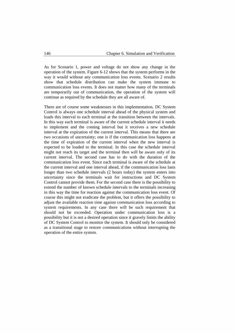
146 Chapter 6. Simulation and Verification
As for Scenario 1, power and voltage do not show any change in the
operation of the system. Figure 6-12 shows that the system performs in the
way it would without any communication loss events. Scenario 2 results
show that schedule distribution can make the system immune to
communication loss events. It does not matter how many of the terminals
are temporarily out of communication, the operation of the system will
continue as required by the schedule they are all aware of.
There are of course some weaknesses in this implementation. DC System
Control is always one schedule interval ahead of the physical system and
loads this interval to each terminal at the transition between the intervals.
In this way each terminal is aware of the current schedule interval it needs
to implement and the coming interval but it receives a new schedule
interval at the expiration of the current interval. This means that there are
two occasions of uncertainty; one is if the communication loss happens at
the time of expiration of the current interval when the new interval is
expected to be loaded to the terminal. In this case the schedule interval
might not reach its target and the terminal then will be aware only of its
current interval. The second case has to do with the duration of the
communication loss event. Since each terminal is aware of the schedule at
the current interval and one interval ahead, if the communication loss lasts
longer than two schedule intervals (2 hours today) the system enters into
uncertainty since the terminals wait for instructions and DC System
Control cannot provide them. For the second case there is the possibility to
extend the number of known schedule intervals to the terminals increasing
in this way the time for reaction against the communication loss event. Of
course this might not eradicate the problem, but it offers the possibility to
adjust the available reaction time against communication loss according to
system requirements. In any case there will be such requirement that
should not be exceeded. Operation under communication loss is a
possibility but it is not a desired operation since it gravely limits the ability
of DC System Control to monitor the system. It should only be considered
as a transitional stage to restore communications without interrupting the
operation of the entire system.
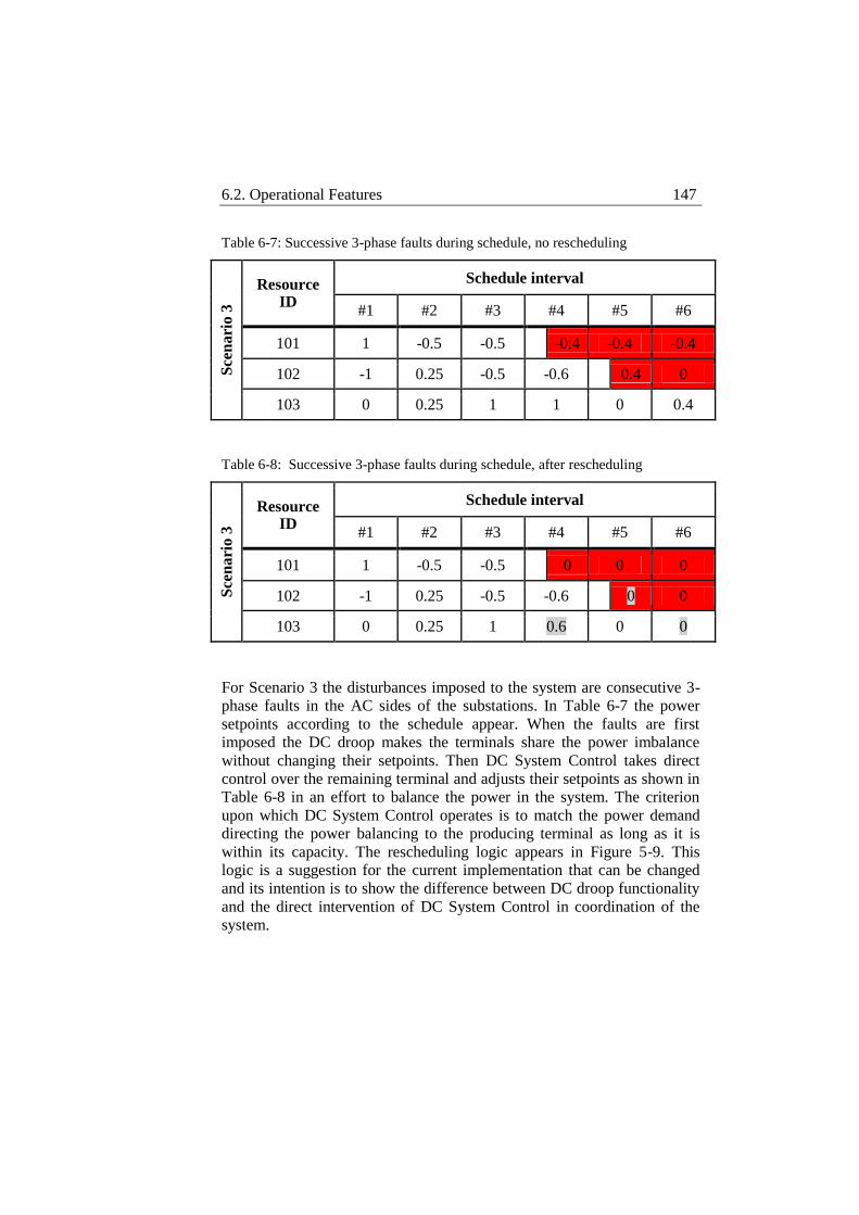
6.2. Operational Features 147
Table 6-7: Successive 3-phase faults during schedule, no rescheduling
Sce
na
rio
3
Resource ID
Schedule interval
#1 #2 #3 #4 #5 #6
101 1 -0.5 -0.5
-0.4 -0.4 -0.4
102 -1 0.25 -0.5 -0.6
0.4 0
103 0 0.25 1 1 0 0.4
Table 6-8: Successive 3-phase faults during schedule, after rescheduling
Sce
nari
o 3
Resource ID
Schedule interval
#1 #2 #3 #4 #5 #6
101 1 -0.5 -0.5
0 0 0
102 -1 0.25 -0.5 -0.6
0 0
103 0 0.25 1 0.6 0 0
For Scenario 3 the disturbances imposed to the system are consecutive 3-
phase faults in the AC sides of the substations. In Table 6-7 the power
setpoints according to the schedule appear. When the faults are first
imposed the DC droop makes the terminals share the power imbalance
without changing their setpoints. Then DC System Control takes direct
control over the remaining terminal and adjusts their setpoints as shown in
Table 6-8 in an effort to balance the power in the system. The criterion
upon which DC System Control operates is to match the power demand
directing the power balancing to the producing terminal as long as it is
within its capacity. The rescheduling logic appears in Figure 5-9. This
logic is a suggestion for the current implementation that can be changed
and its intention is to show the difference between DC droop functionality
and the direct intervention of DC System Control in coordination of the
system.
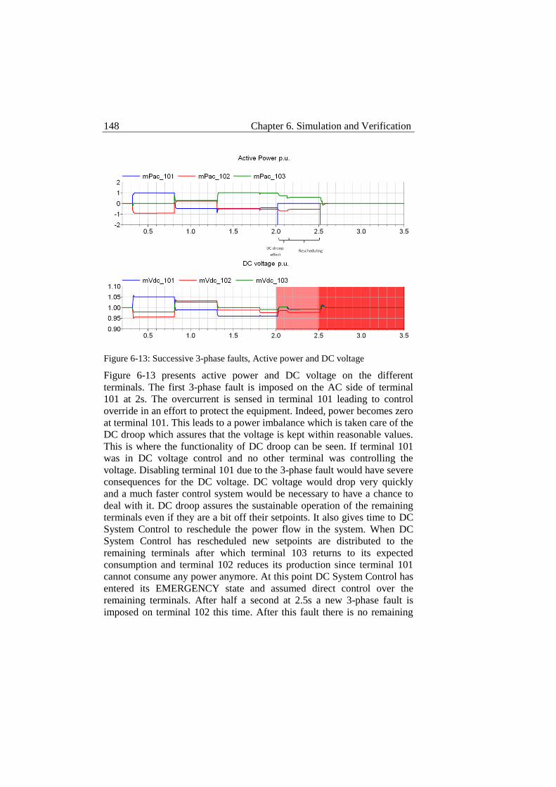
148 Chapter 6. Simulation and Verification
Figure 6-13: Successive 3-phase faults, Active power and DC voltage
Figure 6-13 presents active power and DC voltage on the different
terminals. The first 3-phase fault is imposed on the AC side of terminal
101 at 2s. The overcurrent is sensed in terminal 101 leading to control
override in an effort to protect the equipment. Indeed, power becomes zero
at terminal 101. This leads to a power imbalance which is taken care of the
DC droop which assures that the voltage is kept within reasonable values.
This is where the functionality of DC droop can be seen. If terminal 101
was in DC voltage control and no other terminal was controlling the
voltage. Disabling terminal 101 due to the 3-phase fault would have severe
consequences for the DC voltage. DC voltage would drop very quickly
and a much faster control system would be necessary to have a chance to
deal with it. DC droop assures the sustainable operation of the remaining
terminals even if they are a bit off their setpoints. It also gives time to DC
System Control to reschedule the power flow in the system. When DC
System Control has rescheduled new setpoints are distributed to the
remaining terminals after which terminal 103 returns to its expected
consumption and terminal 102 reduces its production since terminal 101
cannot consume any power anymore. At this point DC System Control has
entered its EMERGENCY state and assumed direct control over the
remaining terminals. After half a second at 2.5s a new 3-phase fault is
imposed on terminal 102 this time. After this fault there is no remaining
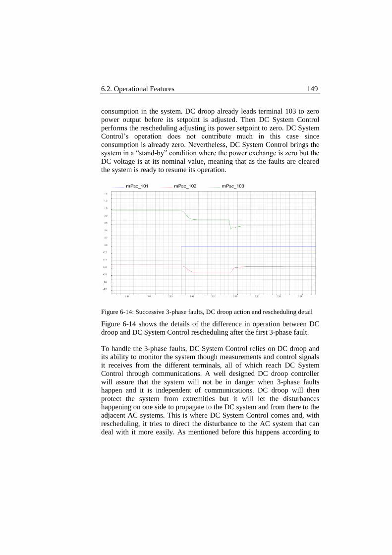
6.2. Operational Features 149
consumption in the system. DC droop already leads terminal 103 to zero
power output before its setpoint is adjusted. Then DC System Control
performs the rescheduling adjusting its power setpoint to zero. DC System
Control’s operation does not contribute much in this case since
consumption is already zero. Nevertheless, DC System Control brings the
system in a “stand-by” condition where the power exchange is zero but the
DC voltage is at its nominal value, meaning that as the faults are cleared
the system is ready to resume its operation.
Figure 6-14: Successive 3-phase faults, DC droop action and rescheduling detail
Figure 6-14 shows the details of the difference in operation between DC
droop and DC System Control rescheduling after the first 3-phase fault.
To handle the 3-phase faults, DC System Control relies on DC droop and
its ability to monitor the system though measurements and control signals
it receives from the different terminals, all of which reach DC System
Control through communications. A well designed DC droop controller
will assure that the system will not be in danger when 3-phase faults
happen and it is independent of communications. DC droop will then
protect the system from extremities but it will let the disturbances
happening on one side to propagate to the DC system and from there to the
adjacent AC systems. This is where DC System Control comes and, with
rescheduling, it tries to direct the disturbance to the AC system that can
deal with it more easily. As mentioned before this happens according to

150 Chapter 6. Simulation and Verification
specific criteria that can be changed. However, the rescheduling operation
of DC System Control assumes continuous monitoring and direct control
of the terminals in the system. A question rising then is what happens if 3-
phase faults are combined with communication loss events. At this point
the proposed control system can only deal with this combination through
DC droop control but it cannot perform any rescheduling.
Chapter 7 Conclusions
In this work the operation and expansion of multi-terminal VSC-HVDC
system were discussed. The drivers that lead to the concept of multi-
terminal VSC-HVDC system were presented and related to the
development of renewables. The technological advancements that made
such a system realistic and the obstacles hampering its development were
discussed, pointing out standardization and expandability as the main
obstacles. The developments of the DC breaker brought the vision of a
European-wide DC grid one step closer but, since such a grid will most
likely be developed by the integration of smaller multi-terminal HVDC
systems, standardization and expandability are crucial both in hardware
equipment and in control system. Standard system operation and control
were discussed pointing out DC droop as the probably most efficient way
to operate a multi-terminal VSC-HVDC system.
A control system structure was proposed to accommodate the standard
control methods for a multi-terminal VSC-HVDC system in a structure
that provides the general features necessary to allow modularity of the
control system to facilitate standardization and thus expandability of the
system. The proposed control system is structured in three control levels
with their distinct responsibilities. One of the most important features is
the uniform interface which provides a common interfacing pattern
between different types of substations and adjacent systems with the
overall control system. The uniform interface decouples the
implementation of the overall control system from the implementation of
substation control as long as the interfacing pattern is respected by both
sides and the expected functionality is fulfilled. Another important general
feature is the automated functions. Since the proposed control system is
expected to be autonomous and require minimum or no human
152 Chapter 7. Conclusions
intervention, it should be able to respond to emergency situations
automatically, both saving reaction time which is valuable due to the fast
dynamics of the system and sustaining its autonomous operation even
under disturbances. The automated functions must fit in the general sense
of the proposed control system structure whose main orientation is
modularity. Modularity in the control system is essential for the system to
be easily expandable. New terminals must be able to be integrated in the
system without any modification in its implementation code. For every
uniform interface the overall control system creates a resource object that
represents the actual connected substation. All the information that needs
to be exchanged then between the actual substation and the overall control
system is exchanged via the uniform interface. Automated functions must
also support this modular functionality and be able to include in their
operation any additional terminal that might be connected to the system.
Automated functions as the coordination operation of the overall control
system must be based on treating the different terminals according to their
properties, without using any external, concrete naming system. The
ambition is that all these general features will lead to a flat control system
structure. The control system itself should not impose any hierarchy
among the different connected terminals or systems so that hierarchies can
be defined externally by using the prioritization system available in the
proposed control system. The flat control system structure will be
particularly useful in the later stage of development of even larger multi-
terminal VSC-HVDC systems when small system will be connected to
form a larger system. Hierarchy among the different systems should then
be a planning procedure that can be implemented according to
requirements.
The proposed control system structure was then implemented, for the
largest part in C++ and partially in Dymola. C++ is essential since an
object oriented approach is necessary to allow modularity in the control
system. A detailed description of this implementation follows and some
test objectives are defined for the control system. Test objectives are
divided in structural and operational. Structural objectives aim to show the
structural features of the proposed control system; that is, correct
functionality of the uniform interface, correct propagation of signals
through the different control levels and the uniform interface, correct
operation of different types of adjacent systems through the uniform
interface and expandability of the system with an additional terminal that
Chapter 7. Conclusions 153
must be integrated in the overall control system operation simply by
connecting through the uniform interface. Operational objectives aim to
show the accurate operation of the system during normal and abnormal
conditions; that is, accurate operation for a given power flow schedule and
smooth transitions from one power flow to another and handling of
disturbances like communication loss events and 3-phase faults on the AC
sides of the system.
The defined test objectives indicated the necessary models to validate
them. For the structural test objectives a test model was developed without
much concern about its ratings since what was to be tested with it was the
correct propagation of signals and easy expandability of the system. For
the operational objectives a verification model was developed. In this case
the model was expected to keep track of power and voltage levels
accurately. Thus, a model with realistic ratings was developed and a
schedule was implemented on it. This schedule was used as the base
scenario on which different sets of disturbances were tested.
Some conclusions can be drawn looking at the results of the two sets of
simulations. Structurally the control system functioned as expected. The
implemented labeling identity system that was used by the uniform
interface kept right track of the signals in the system which reached their
target every time. The information of the type of the connected system in
the uniform interface prevented DC System Control from making wrong
decisions. This is obvious in the selection of the unit to charge the DC
link, no load unit was selected for that, it was excluded because DC
System Control had this information. The data set of the uniform interface
was flexible too, since it was changed between the two simulations sets.
Most importantly from a structural point of view, the additional terminal
was connected through the uniform interface and immediately identified
and operated by DC System Control. The general search functions in DC
System Control help it operate on the properties of the different terminal
that become known to it through the uniform interfaces. In this way the
number of connected terminals is irrelevant to the operation of DC System
Control.
Operationally, the proposed control system was able to accommodate a
different implementation of the Substation and Converter control levels,
with a different data set for the uniform interface and expanded DC
154 Chapter 7. Conclusions
System Control functionalities and operate the system successfully. A
given schedule functioned as the base scenario which was implemented
accurately providing smooth transitions from one power flow to another.
In this set of simulations the two different ways of control of DC System
Control were also tested side by side. Indirect control, or Schedule
Management, was used during the normal operation of the system
distributing the schedule to the individual substations. This gave the
different substations a higher degree of autonomy and let DC System
Control perform the overall monitoring. The practice of Schedule
Management left the system unaffected when communication loss events
happened. Since all the substations were aware of their expected operation
for the current schedule interval and the interval to come, substations
performed the transition in power flows from one interval to another in an
uncoordinated way but successfully. Even though Schedule Management
prevented the consequences of communication loss, it raised some issues
also. Having the substations knowing the schedule intervals to come
prolongs the reaction time the system has to recover from communication
losses, but it links the duration of reaction time to the duration of the
intervals. Today, the schedule interval is one hour long, although there are
discussions about reducing it to half an hour or even 15 minutes to achieve
better power resolution. In this case the benefit of distributing the schedule
interval to come would be insignificant since instead of gaining one more
hour, the gain would only be extra 15 minutes greatly reducing the chances
of the system to overcome a communication loss event. It is possible
though in the proposed control system to increase the number of before-
hand known schedule intervals. Then, the reaction time is decoupled from
the duration of the schedule interval, since according to the duration of the
schedule interval and the number of before-hand known intervals the
available reaction time can be adjusted according to the requirements of
the system. In any case, communication loss is a severe disturbance to the
system. DC System Control not only cannot control the substation out of
communication but it cannot receive any feedback from it either. In this
sense DC System Control is “blind” towards the substation out of
communication and it has to monitor closely the rest of the substations to
intervene if necessary. It becomes even worse if all terminals are out of
communication. In this case DC System Control has no authority over the
system which operates in an uncoordinated manner. If another disturbance
happens at this time, DC System Control will be unable to deal with it.
Chapter 7. Conclusions 155
Communication loss in this sense is a potentially very severe disturbance
and prolonged operation under communication loss must be avoided.
When it comes to 3-phase faults, the proposed control system responds in
different levels. First, the Converter Control level in the faulted terminal
prevents equipment damage by circumventing any control request and
controlling the converter to zero power output. At the same time an error
signal is sent to DC System Control. The rest of the terminals immediately
see the power imbalance created by the faulted terminal shutdown. DC
droop balances the power in the DC system by distributing the lost power
to the remaining terminals. In this way, power setpoints are not accurately
followed and the disturbance diffuses in the adjacent systems. DC System
Control then intervenes; it assumes direct control of the remaining
terminals and readjusts their power setpoints. Operational Management
overrides Schedule Management in this case. Anyway, since one of the
terminals is not operational the schedule cannot be implemented. The
priority is to maintain the operation of the remaining terminals and limit
the propagation of the disturbance to the adjacent systems. This test proves
the necessity of DC droop control in the primary control of the system. DC
droop kept the DC voltage at reasonable levels. If DC voltage control was
used instead and the disabled terminal was the one controlling the DC
voltage the disturbance on the DC voltage would be so severe that DC
System Control would not have the time to reverse the situation. This test
also shows that DC System Control can identify emergencies in the system
and be used to facilitate the operation of the system even in emergency
conditions. As mentioned before the rescheduling logic implemented here
aims at matching the power demand in the system which means that it is
assumed that the remaining producing terminal is able to cover the power
mismatch created by the shutdown of the faulted terminal not to reduce the
power delivered to the consuming terminal. This logic can be changed or
expanded to match the requirements of each system; new criteria can be
implemented according to the characteristics of each adjacent system or
prioritization according to agreements between the involved parts. Three
phase faults were tested in this work since they are considered to be the
most severe AC faults. It is assumed that different types of AC faults will
require different treatment and different detection mechanism. A faulted
terminal might not need to be shut down then, creating new scenarios for
the rescheduling procedure since part of the capacity of the faulted
terminal might be available.
156 Chapter 7. Conclusions
In all, the proposed control system showed adequate behavior according to
the requirements set in the beginning. It was able to operate a 3-terminal
system accurately and deal with communication loss events and 3-phase
faults. It also proved the value of the uniform interfacing when connecting
different types of adjacent systems and when additional terminals are to be
integrated. The proposed control system structure also showed its
flexibility in accepting different implementations of its different parts.
Throughout the tests, Substation and Converter control level
implementation was changed and DC System Control level
implementation was expanded to include further functionality. The data set
of the uniform interface was also changed, adjusted and expanded from
one set of simulations to another. The proposed control system structure
seems to be adequate to play the role of the control system platform
mentioned in the beginning of this work, and the proposed control system
implementation seems adequate to be the basis on which a general control
system can be developed.
Chapter 8 Future Work
In the scope of this work a general control system structure was proposed
with the intention to contribute against the lack of standardization in
today’s plans for multi-terminal VSC-HVDC systems and promote their
expandability through modularity and uniform interfacing. The control
system structure and implementation were described in detail and its
functionality was validated through simulations on, mainly, 3-terminal
systems. Although 3-terminal systems are adequate to prove the control
system structure and main functionality, they remain the simplest form of
a multi-terminal system. It seems as a natural continuation of this project
that the proposed control system is tested on more complex multi-terminal
arrangements featuring more terminals and in meshes with consideration
of DC breakers. Due to the fast dynamics of a multi-terminal VSC-HVDC
system automated functions are imperative, thus the operation of DC
breakers must be integrated in the functionality of the control system and
system’s topology identification after DC breakers’ operation must be
performed by the control system in a very short span of time. Power flow
calculation methods must also be considered and fit both the modularity of
the system and the requirements for the aftermath of DC breakers’
operation.
As mentioned earlier 3-phase faults are considered to be the most severe
and this is the reason why they have been investigated in this work, but
under no circumstances are enough to cover all cases. Different types of
AC faults must be investigated both in terms of fault detection and
counteraction. Experience in AC power systems have a lot to teach
regarding the behavior and effect of AC faults but how to integrate the
counter-measures required in the proposed control system to minimize
158 Chapter 8. Future Work
their effect on the DC system and the substation equipment is a point of
further investigation. In addition, if DC breakers are considered, DC faults
must be addressed also. The proposed control system must take
responsibility to deal with DC faults as well since the tools for that are
considered. New general algorithms might be necessary to deal with all a
wide range of electrical faults both of AC and DC nature. An important
type of fault of no electrical nature is communication loss as discussed in
this work. Schedule distribution has been suggested to anticipate this type
of events but, as mentioned, operating under communication loss is an
uncoordinated operation and a minor disturbance might have more serious
consequences. In this sense, ahead in time schedule distribution is a
temporary solution but how far ahead is too far? As discussed earlier the
arbitrary number of schedule intervals that can be distributed before-hand
can determine the available reaction time for the system to recover from
communication loss events. The question rising is how long should the
system be allowed to operate in an uncoordinated way before the risk for
the rest of the system becomes too high. Investigating combined
disturbances will also be of great interest. The behavior of a system that
suffers different types of faults under communication loss is an issue to be
addressed and criteria for the rescheduling of the power flows of the
remaining healthy terminals must be developed.
Another interesting point for further investigation is the parallel operation
of many systems. Since the integrated large DC grid will be formed by
several multi-terminal systems that will probably form their own control
area, the parallel operation and interfacing of many systems is necessary.
This might later on call for another, higher level of overall control to
coordinate the different areas.
References
[1] Jiang-Häfner, Y. and Ottersten, R. (2009). HVDC with Voltage
Source Converters – A Desirable Solution for Connecting
Renewable Energies, 8th International Workshop on Large-scale
integration of wind power into power systems, Bremen, Germany,
Oct 14-15, 2009.
[2] Chokhawala, R., Danielsson, B. and Ängquist, L. (2001). Power
Semiconductors in Transmission and Distribution Applications,
Proceedings of 2001 International Symposium on Power
Semiconductor Devices & ICs, Osaka, Japan, Jun 4-7, 2001.
[3] Johansson, S., Asplund, G., Jansson, E. and Rudervall, R. (2004).
Power System Stability Benefits with VSC DC-Transmission
Systems, CIGRÉ Conference, Paris, France, Aug 29- Sep 3, 2004.
[4] Flourentzou, N., Agelidis, V. and Demetriades, G. (2009). VSC-
Based HVDC Power Transmission Systems: An Overview. IEEE
Transactions on Power Electronics, vol. 24, no. 3, pp. 592-602.
[5] Gomis-Bellmunt, O., Liang, J., Ekanayake, J., King, R. and
Jenkins, N. (2011). Topologies of multiterminal HVDC-VSC
transmission for large offshore wind farms. Electric Power
Systems Research, vol. 81, no. 2, pp. 271–281.
[6] Xu, L., Yao, L., Bazargan, M. and Wang, Y. (2010). The Role of
Multiterminal HVDC for Wind Power Transmission and AC
Network Support, Power and Energy Engineering Conference
(APPEEC), 2010 Asia-Pacific, Chengdu, China, Mar 28-31, 2010.
[7] Retzmann, D., Kreusel, J. and Povh, D. (2008). Integrated AC/DC
Transmission Systems -Benefits of Power Electronics for Security
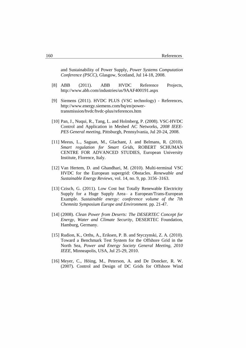
160 References
and Sustainability of Power Supply, Power Systems Computation
Conference (PSCC), Glasgow, Scotland, Jul 14-18, 2008.
[8] ABB (2011). ABB HVDC Reference Projects,
http://www.abb.com/industries/us/9AAF400191.aspx
[9] Siemens (2011). HVDC PLUS (VSC technology) - References,
http://www.energy.siemens.com/hq/en/power-
transmission/hvdc/hvdc-plus/references.htm
[10] Pan, J., Nuqui, R., Tang, L. and Holmberg, P. (2008). VSC-HVDC
Control and Application in Meshed AC Networks, 2008 IEEE-
PES General meeting, Pittsburgh, Pennsylvania, Jul 20-24, 2008.
[11] Meeus, L., Saguan, M., Glachant, J. and Belmans, R. (2010).
Smart regulation for Smart Grids, ROBERT SCHUMAN
CENTRE FOR ADVANCED STUDIES, European University
Institute, Florence, Italy.
[12] Van Hertem, D. and Ghandhari, M. (2010). Multi-terminal VSC
HVDC for the European supergrid: Obstacles. Renewable and
Sustainable Energy Reviews, vol. 14, no. 9, pp. 3156–3163.
[13] Czisch, G. (2011). Low Cost but Totally Renewable Electricity
Supply for a Huge Supply Area– a European/Trans-European
Example. Sustainable energy: conference volume of the 7th
Chemnitz Symposium Europe and Environment. pp. 21-47.
[14] (2008). Clean Power from Deserts: The DESERTEC Concept for
Energy, Water and Climate Security, DESERTEC Foundation,
Hamburg, Germany.
[15] Rudion, K., Orths, A., Eriksen, P. B. and Styczynski, Z. A. (2010).
Toward a Benchmark Test System for the Offshore Grid in the
North Sea, Power and Energy Society General Meeting, 2010
IEEE, Minneapolis, USA, Jul 25-29, 2010.
[16] Meyer, C., Höing, M., Peterson, A. and De Doncker, R. W.
(2007). Control and Design of DC Grids for Offshore Wind
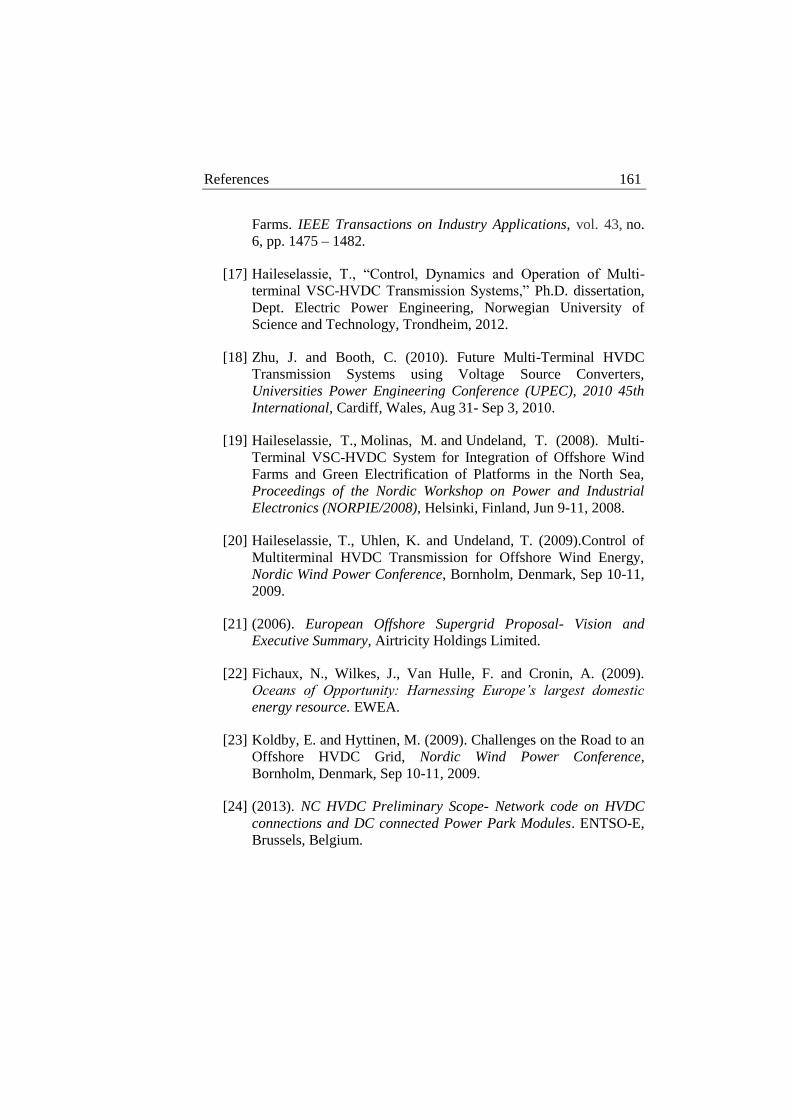
References 161
Farms. IEEE Transactions on Industry Applications, vol. 43, no.
6, pp. 1475 – 1482.
[17] Haileselassie, T., “Control, Dynamics and Operation of Multi-
terminal VSC-HVDC Transmission Systems,” Ph.D. dissertation,
Dept. Electric Power Engineering, Norwegian University of
Science and Technology, Trondheim, 2012.
[18] Zhu, J. and Booth, C. (2010). Future Multi-Terminal HVDC
Transmission Systems using Voltage Source Converters,
Universities Power Engineering Conference (UPEC), 2010 45th
International, Cardiff, Wales, Aug 31- Sep 3, 2010.
[19] Haileselassie, T., Molinas, M. and Undeland, T. (2008). Multi-
Terminal VSC-HVDC System for Integration of Offshore Wind
Farms and Green Electrification of Platforms in the North Sea,
Proceedings of the Nordic Workshop on Power and Industrial
Electronics (NORPIE/2008), Helsinki, Finland, Jun 9-11, 2008.
[20] Haileselassie, T., Uhlen, K. and Undeland, T. (2009).Control of
Multiterminal HVDC Transmission for Offshore Wind Energy,
Nordic Wind Power Conference, Bornholm, Denmark, Sep 10-11,
2009.
[21] (2006). European Offshore Supergrid Proposal- Vision and
Executive Summary, Airtricity Holdings Limited.
[22] Fichaux, N., Wilkes, J., Van Hulle, F. and Cronin, A. (2009).
Oceans of Opportunity: Harnessing Europe’s largest domestic
energy resource. EWEA.
[23] Koldby, E. and Hyttinen, M. (2009). Challenges on the Road to an
Offshore HVDC Grid, Nordic Wind Power Conference,
Bornholm, Denmark, Sep 10-11, 2009.
[24] (2013). NC HVDC Preliminary Scope- Network code on HVDC
connections and DC connected Power Park Modules. ENTSO-E,
Brussels, Belgium.
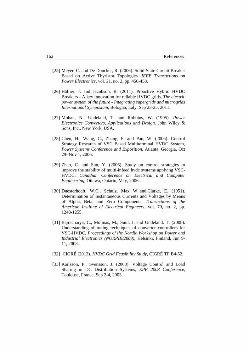
162 References
[25] Meyer, C. and De Doncker, R. (2006). Solid-State Circuit Breaker
Based on Active Thyristor Topologies. IEEE Transactions on
Power Electronics, vol. 21, no. 2, pp. 450-458.
[26] Häfner, J. and Jacobson, B. (2011). Proactive Hybrid HVDC
Breakers - A key innovation for reliable HVDC grids, The electric
power system of the future - Integrating supergrids and microgrids
International Symposium, Bologna, Italy, Sep 23-25, 2011.
[27] Mohan, N., Undeland, T. and Robbins, W. (1995). Power
Electronics Converters, Applications and Design. John Wiley &
Sons, Inc., New York, USA.
[28] Chen, H., Wang, C., Zhang, F. and Pan, W. (2006). Control
Strategy Research of VSC Based Multiterminal HVDC System,
Power Systems Conference and Exposition, Atlanta, Georgia, Oct
29- Nov 1, 2006.
[29] Zhao, C. and Sun, Y. (2006). Study on control strategies to
improve the stability of multi-infeed hvdc systems applying VSC-
HVDC, Canadian Conference on Electrical and Computer
Engineering, Ottawa, Ontario, May, 2006.
[30] Duesterhoeft, W.C., Schulz, Max W. and Clarke, E. (1951).
Determination of Instantaneous Currents and Voltages by Means
of Alpha, Beta, and Zero Components, Transactions of the
American Institute of Electrical Engineers, vol. 70, no. 2, pp.
1248-1255.
[31] Bajracharya, C., Molinas, M., Suul, J. and Undeland, T. (2008).
Understanding of tuning techniques of converter controllers for
VSC-HVDC, Proceedings of the Nordic Workshop on Power and
Industrial Electronics (NORPIE/2008), Helsinki, Finland, Jun 9-
11, 2008.
[32] CIGRÉ (2013). HVDC Grid Feasibility Study, CIGRÉ TF B4-52.
[33] Karlsson, P., Svensson, J. (2003). Voltage Control and Load
Sharing in DC Distribution Systems, EPE 2003 Conference,
Toulouse, France, Sep 2-4, 2003.

References 163
[34] Xu, L., Yao, L. and Bazargan, M. (2009). DC Grid Management
of a Multi-Terminal HVDC Transmission System for Large
Offshore Wind Farms, International Conference on Sustainable
Power Generation and Supply, Nanjing, China, Apr 6-7, 2009.
[35] De Brabandere, K., Bolsens, B., Van den Keybus, J., Woyte, A.,
Driesen, J. and Belmans, R. (2004). A Voltage and Frequency
Droop Control Method for Parallel Inverters, IEEE 35th Annual
Power Electronics Specialists Conference, Aachen, Germany, Jun
20-26, 2004.
[36] Xu, L. and Yao, L. (2011). DC voltage control and power dispatch
of a multi-terminal HVDC system for integrating large offshore
wind farms. Renewable Power Generation, IET, vol. 5, no. 3, pp.
223-233.
[37] Liang, J., Jing, T., Gomis-Bellmunt, O., Ekanayake, J. and
Jenkins, N. (2011). Operation and Control of Multiterminal
HVDC Transmission for Offshore Wind Farms. IEEE
Transactions on Power Delivery, vol. 26, no. 4, pp. 2596-2604.
[38] Svensson, J., “Active Distributed Power Systems- Functional
Structures for Real-Time Operation of Sustainable Energy
Systems,” Ph.D. dissertation, Dept. Industrial Electrical
Engineering and Automation, Lund University, Lund, 2006.
[39] Brand, K.-P. (2004). The standard IEC 61850 as prerequisite for
intelligent applications in substations, 2004 IEEE Power
Engineering Society General Meeting, Denver, Colorado, Jun 6-
10, 2004.
[40] Sidhu, T.S. and Gangadharan, P.K. (2005). Control and
automation of power system substation using IEC61850
communication, IEEE Conference on Control Applications,
Toronto, Ontario, Aug 28-31, 2005.
[41] Mackiewicz, R.E. (2006). Overview of IEC 61850 and Benefits,
2005/2006 IEEE PES Transmission and Distribution Conference
and Exhibition, Dallas, Texas, May 21-24, 2006.

164 References
[42] Brunner, C. (2008). IEC 61850 for power system communication,
2008 IEEE/PES Transmission and Distribution Conference and
Exposition, Chicago, Illinois, Apr 21-24, 2008.