Embed Size (px)
Citation preview
UPTEC IT11 014
Examensarbete 30 hpDecember 2011
Unambiguous requirements in Functional Safety and ISO 26262: dream or reality?
Patrik Sternudd

Teknisk- naturvetenskaplig fakultet UTH-enheten Besöksadress: Ångströmlaboratoriet Lägerhyddsvägen 1 Hus 4, Plan 0 Postadress: Box 536 751 21 Uppsala Telefon: 018 – 471 30 03 Telefax: 018 – 471 30 00 Hemsida: http://www.teknat.uu.se/student
Abstract
Unambiguous requirements in Functional Safety andISO 26262: dream or reality?
Patrik Sternudd
Functional Safety is becoming an increasingly important concern for in-vehicle E/E systems. In 2011 a new international standard, ISO 26262 "Functional safety - Road vehicles" was published, in which requirements play an important role.
In this thesis, the advantages and disadvantages of different levels of formality in requirement notations are discussed. It is found that the higher the level of formality, the less ambiguous will the requirements specified in the notation be. Furthermore, it is found that ISO 26262 mandate that all requirements must be unambiguous and at the same time preferably written in natural language. This is considered inconsistent since natural language is inherently ambiguous.
A case study is performed where a domain ontology and a constrained natural language (CNL) in the form of boilerplates are used to write and analyse requirements. An important conclusion is that getting requirements right is a hard task, but that the use of ontologies both can decrease ambiguity and establish a shared vocabulary among stakeholders.
Tryckt av: Reprocentralen ITCISSN: 1401-5749, UPTEC IT11 014Examinator: Anders JanssonÄmnesgranskare: Lars-Henrik ErikssonHandledare: Mattias Nyberg

Acknowledgements
I would like to thank the following people for their involvement and contributions duringthe preparation of this master thesis:
Mattias Nyberg who supervised this project at Scania and offered feedback throughout theprocess.
Lars-Henrik Eriksson, reviewer at Uppsala University (Department of Information Tech-nology), for project guidance and for being a resource in matters concerning formal meth-ods.
Roland Bol at Uppsala University (Department of Information Technology), for being aresource for questions related to Software and Requirements Engineering.
Tor Stålhane and Stefan Farfeleder for providing access to the tool DODT that was used inthe case study, and also being helpful in other matters regarding the tool.
Anna Sågvall Hein, professor emerita at Uppsala University (Department of Linguisticsand Philology), for information about the Scania Checker project, and also for being a re-source for the linguistic questions that arose.
The other thesis workers at the REPA department at Scania, for all discussions regardingISO 26262, functional safety and other related topics.
The staff and thesis workers at the REPA department for a fun time together during themonths that were spent at the Scania R&D offices in Södertälje.
Thank you, all!

Contents
Acknowledgements . . . . . . . . . . . . . . . . . . . . . . . . . . . . . . . . . . . . . . . . . . . . . . . . . . . . . . . . . . . . . . . . . . . . . . . . . . . . . . . . . . . . . . . . . . . . . . . . . . . . . . . . . . . . . . . . . v
About Scania CV . . . . . . . . . . . . . . . . . . . . . . . . . . . . . . . . . . . . . . . . . . . . . . . . . . . . . . . . . . . . . . . . . . . . . . . . . . . . . . . . . . . . . . . . . . . . . . . . . . . . . . . . . . . . . . . . . . . . . ix
Part I: Background . . . . . . . . . . . . . . . . . . . . . . . . . . . . . . . . . . . . . . . . . . . . . . . . . . . . . . . . . . . . . . . . . . . . . . . . . . . . . . . . . . . . . . . . . . . . . . . . . . . . . . . . . . . . . . . . . 11
1 Introduction . . . . . . . . . . . . . . . . . . . . . . . . . . . . . . . . . . . . . . . . . . . . . . . . . . . . . . . . . . . . . . . . . . . . . . . . . . . . . . . . . . . . . . . . . . . . . . . . . . . . . . . . . . . . . . . . . . . . . . 13
2 Key concepts . . . . . . . . . . . . . . . . . . . . . . . . . . . . . . . . . . . . . . . . . . . . . . . . . . . . . . . . . . . . . . . . . . . . . . . . . . . . . . . . . . . . . . . . . . . . . . . . . . . . . . . . . . . . . . . . . . . . . 15
3 Functional Safety and ISO 26262 . . . . . . . . . . . . . . . . . . . . . . . . . . . . . . . . . . . . . . . . . . . . . . . . . . . . . . . . . . . . . . . . . . . . . . . . . . . . . . . . . . . . . 20
Glossary . . . . . . . . . . . . . . . . . . . . . . . . . . . . . . . . . . . . . . . . . . . . . . . . . . . . . . . . . . . . . . . . . . . . . . . . . . . . . . . . . . . . . . . . . . . . . . . . . . . . . . . . . . . . . . . . . . . . . . . . . . . . . . . . . . 23
Acronyms . . . . . . . . . . . . . . . . . . . . . . . . . . . . . . . . . . . . . . . . . . . . . . . . . . . . . . . . . . . . . . . . . . . . . . . . . . . . . . . . . . . . . . . . . . . . . . . . . . . . . . . . . . . . . . . . . . . . . . . . . . . . . . . 25
Part II: Related work and method . . . . . . . . . . . . . . . . . . . . . . . . . . . . . . . . . . . . . . . . . . . . . . . . . . . . . . . . . . . . . . . . . . . . . . . . . . . . . . . . . . . . . . . . . 27
4 Related work . . . . . . . . . . . . . . . . . . . . . . . . . . . . . . . . . . . . . . . . . . . . . . . . . . . . . . . . . . . . . . . . . . . . . . . . . . . . . . . . . . . . . . . . . . . . . . . . . . . . . . . . . . . . . . . . . . . . . 29
5 Method . . . . . . . . . . . . . . . . . . . . . . . . . . . . . . . . . . . . . . . . . . . . . . . . . . . . . . . . . . . . . . . . . . . . . . . . . . . . . . . . . . . . . . . . . . . . . . . . . . . . . . . . . . . . . . . . . . . . . . . . . . . . . . 33
Part III: Current and future practices . . . . . . . . . . . . . . . . . . . . . . . . . . . . . . . . . . . . . . . . . . . . . . . . . . . . . . . . . . . . . . . . . . . . . . . . . . . . . . . . . . . . 37
6 Structure and elements of requirements . . . . . . . . . . . . . . . . . . . . . . . . . . . . . . . . . . . . . . . . . . . . . . . . . . . . . . . . . . . . . . . . . . . . . . . . . 39
6.1 Why requirements matter . . . . . . . . . . . . . . . . . . . . . . . . . . . . . . . . . . . . . . . . . . . . . . . . . . . . . . . . . . . . . . . . . . . . . . . . . . . . . . . . . . . . . 39
6.2 Using requirements throughout the process . . . . . . . . . . . . . . . . . . . . . . . . . . . . . . . . . . . . . . . . . . . . . . . . . . . . . . . . 39
6.3 Requirements, Lean, and Agile . . . . . . . . . . . . . . . . . . . . . . . . . . . . . . . . . . . . . . . . . . . . . . . . . . . . . . . . . . . . . . . . . . . . . . . . . . . . . 40
6.4 Properties and attributes of requirements . . . . . . . . . . . . . . . . . . . . . . . . . . . . . . . . . . . . . . . . . . . . . . . . . . . . . . . . . . . . 41
6.5 Documents are no longer sufficient . . . . . . . . . . . . . . . . . . . . . . . . . . . . . . . . . . . . . . . . . . . . . . . . . . . . . . . . . . . . . . . . . . . . . . 43
7 Notations for requirements . . . . . . . . . . . . . . . . . . . . . . . . . . . . . . . . . . . . . . . . . . . . . . . . . . . . . . . . . . . . . . . . . . . . . . . . . . . . . . . . . . . . . . . . . . . . . . 44
7.1 Levels of formality . . . . . . . . . . . . . . . . . . . . . . . . . . . . . . . . . . . . . . . . . . . . . . . . . . . . . . . . . . . . . . . . . . . . . . . . . . . . . . . . . . . . . . . . . . . . . . . . . 44
7.2 Directives from ISO 26262 . . . . . . . . . . . . . . . . . . . . . . . . . . . . . . . . . . . . . . . . . . . . . . . . . . . . . . . . . . . . . . . . . . . . . . . . . . . . . . . . . . . . . 50
8 Semantics and domain knowledge . . . . . . . . . . . . . . . . . . . . . . . . . . . . . . . . . . . . . . . . . . . . . . . . . . . . . . . . . . . . . . . . . . . . . . . . . . . . . . . . . 54
8.1 The need for semantics . . . . . . . . . . . . . . . . . . . . . . . . . . . . . . . . . . . . . . . . . . . . . . . . . . . . . . . . . . . . . . . . . . . . . . . . . . . . . . . . . . . . . . . . . . 54
8.2 Improving communication . . . . . . . . . . . . . . . . . . . . . . . . . . . . . . . . . . . . . . . . . . . . . . . . . . . . . . . . . . . . . . . . . . . . . . . . . . . . . . . . . . . 54
8.3 Towards automated reasoning . . . . . . . . . . . . . . . . . . . . . . . . . . . . . . . . . . . . . . . . . . . . . . . . . . . . . . . . . . . . . . . . . . . . . . . . . . . . . . 55
8.4 Requirements metrics . . . . . . . . . . . . . . . . . . . . . . . . . . . . . . . . . . . . . . . . . . . . . . . . . . . . . . . . . . . . . . . . . . . . . . . . . . . . . . . . . . . . . . . . . . . . 56
Part IV: Case study . . . . . . . . . . . . . . . . . . . . . . . . . . . . . . . . . . . . . . . . . . . . . . . . . . . . . . . . . . . . . . . . . . . . . . . . . . . . . . . . . . . . . . . . . . . . . . . . . . . . . . . . . . . . . . . . . 61
9 Case study: CNL with semantics on top . . . . . . . . . . . . . . . . . . . . . . . . . . . . . . . . . . . . . . . . . . . . . . . . . . . . . . . . . . . . . . . . . . . . . . . . 63
9.1 Scenario . . . . . . . . . . . . . . . . . . . . . . . . . . . . . . . . . . . . . . . . . . . . . . . . . . . . . . . . . . . . . . . . . . . . . . . . . . . . . . . . . . . . . . . . . . . . . . . . . . . . . . . . . . . . . . . . . . 63
9.2 Using DODT . . . . . . . . . . . . . . . . . . . . . . . . . . . . . . . . . . . . . . . . . . . . . . . . . . . . . . . . . . . . . . . . . . . . . . . . . . . . . . . . . . . . . . . . . . . . . . . . . . . . . . . . . . . 64
9.3 Evaluation . . . . . . . . . . . . . . . . . . . . . . . . . . . . . . . . . . . . . . . . . . . . . . . . . . . . . . . . . . . . . . . . . . . . . . . . . . . . . . . . . . . . . . . . . . . . . . . . . . . . . . . . . . . . . . 76
Part V: Discussion . . . . . . . . . . . . . . . . . . . . . . . . . . . . . . . . . . . . . . . . . . . . . . . . . . . . . . . . . . . . . . . . . . . . . . . . . . . . . . . . . . . . . . . . . . . . . . . . . . . . . . . . . . . . . . . . . . 81
10 Discussion . . . . . . . . . . . . . . . . . . . . . . . . . . . . . . . . . . . . . . . . . . . . . . . . . . . . . . . . . . . . . . . . . . . . . . . . . . . . . . . . . . . . . . . . . . . . . . . . . . . . . . . . . . . . . . . . . . . . . . . . . 83
10.1 Ambiguities in ISO 26262 . . . . . . . . . . . . . . . . . . . . . . . . . . . . . . . . . . . . . . . . . . . . . . . . . . . . . . . . . . . . . . . . . . . . . . . . . . . . . . . . . . . . . . 83
10.2 Uniform management of requirements . . . . . . . . . . . . . . . . . . . . . . . . . . . . . . . . . . . . . . . . . . . . . . . . . . . . . . . . . . . . . . . . 84
10.3 Domain ontologies, boilerplates and DODT . . . . . . . . . . . . . . . . . . . . . . . . . . . . . . . . . . . . . . . . . . . . . . . . . . . . . . . . 85
10.4 Notations - which one is best? . . . . . . . . . . . . . . . . . . . . . . . . . . . . . . . . . . . . . . . . . . . . . . . . . . . . . . . . . . . . . . . . . . . . . . . . . . . . . . 87
Part VI: Conclusions and future work . . . . . . . . . . . . . . . . . . . . . . . . . . . . . . . . . . . . . . . . . . . . . . . . . . . . . . . . . . . . . . . . . . . . . . . . . . . . . . . . . . 89
11 Conclusions . . . . . . . . . . . . . . . . . . . . . . . . . . . . . . . . . . . . . . . . . . . . . . . . . . . . . . . . . . . . . . . . . . . . . . . . . . . . . . . . . . . . . . . . . . . . . . . . . . . . . . . . . . . . . . . . . . . . . . 91
11.1 Requirements in general . . . . . . . . . . . . . . . . . . . . . . . . . . . . . . . . . . . . . . . . . . . . . . . . . . . . . . . . . . . . . . . . . . . . . . . . . . . . . . . . . . . . . . . . 91
11.2 Requirements, ambiguity and ISO 26262 . . . . . . . . . . . . . . . . . . . . . . . . . . . . . . . . . . . . . . . . . . . . . . . . . . . . . . . . . . . . . 92
11.3 Ontologies and constrained natural language . . . . . . . . . . . . . . . . . . . . . . . . . . . . . . . . . . . . . . . . . . . . . . . . . . . . . 92
12 Future work . . . . . . . . . . . . . . . . . . . . . . . . . . . . . . . . . . . . . . . . . . . . . . . . . . . . . . . . . . . . . . . . . . . . . . . . . . . . . . . . . . . . . . . . . . . . . . . . . . . . . . . . . . . . . . . . . . . . . . 94
12.1 Scania specific . . . . . . . . . . . . . . . . . . . . . . . . . . . . . . . . . . . . . . . . . . . . . . . . . . . . . . . . . . . . . . . . . . . . . . . . . . . . . . . . . . . . . . . . . . . . . . . . . . . . . . . . 94
12.2 General . . . . . . . . . . . . . . . . . . . . . . . . . . . . . . . . . . . . . . . . . . . . . . . . . . . . . . . . . . . . . . . . . . . . . . . . . . . . . . . . . . . . . . . . . . . . . . . . . . . . . . . . . . . . . . . . . . . 95
Bibliography . . . . . . . . . . . . . . . . . . . . . . . . . . . . . . . . . . . . . . . . . . . . . . . . . . . . . . . . . . . . . . . . . . . . . . . . . . . . . . . . . . . . . . . . . . . . . . . . . . . . . . . . . . . . . . . . . . . . . . . . . . . 96
About Scania CV
For the benefit of the reader, a brief introduction about Scania CV is provided in the belowquote, which is copied verbatim from the corporate website:
Scania’s objective is to deliver optimised heavy trucks and buses, engines and services, providethe best total operating economy for our customers, and thereby be the leading company in ourindustry. The foundation is our core values, our focus on methods and the dedicated peopleof Scania.
Scania operates in about 100 countries and has more than 35,500 employees. Of these, around15,000 work with sales and services in Scania’s own subsidiaries around the world. About12,300 people work at production units in seven countries and delivery centres in six emergingmarkets. Research and development operations are concentrated in Södertälje, Sweden, andemploy some 2,900 people. Scania’s Head Office is located in Södertälje, the workplace of mostof the 5,300 people who perform administrative and other tasks. Scania’s corporate purchasingdepartment in Södertälje is supplemented by local procurement offices in Poland, the CzechRepublic, the United States, China and Russia.
Scania’s identity is shaped by its customers and products – vehicles, services and financing –and by the people in the company, their values and working methods.
Three core values – Customer first, Respect for the individual and Quality – tie the companytogether and form the basis of Scania’s culture, leadership and business success.
Scania’s modular product system, with a limited number of main components, allows a highdegree of customisation, while keeping down the cost of product development and produc-tion as well as parts management. Tailoring each vehicle to specific transport needs gives thecustomer better overall operating economy.
Scania should contribute to sustainable economic growth, for the company, our customersand society at large. As an industry leader in sustainable efforts, Scania works together withgovernments, customers and organisations to provide reliable energy-efficient products andsolutions that increase customer efficiency and contribute to a more sustainable society. [46]


Part I:
Background

1. Introduction
The advances of the last decade in E/E (Electrical/Electronic) systems have made it possibleto build increasingly advanced in-vehicle systems. The number of such systems in eachindividual vehicle has also increased, as has the complexity within each specific system.
This trend is likely to continue, especially in the field of ADAS (Advanced Driver Assis-tance Systems). As the E/E systems also becomes increasingly responsible for maintainingthe safety of the vehicle and its environment, the correctness of the systems becomes im-perative. This in turn puts higher demands on the development processes.
In November 2011, ISO 26262 “Road Vehicles – Functional Safety” [31] was published as aformal ISO standard, but draft versions have been available to interested parties for sometime prior to the publication. ISO 26262 is a domain specific realisation of the IEC 61508standard, which covers functional safety in E/E systems.
ISO 26262 is applicable only for vehicles with a weight less than 3500 kg, but it is expectedthat heavier road vehicles will be encompassed after the first revision of the standard. Sca-nia CV, which has commissioned this thesis, is interested in knowing what impact the stan-dard would have on their work processes if it were to be adhered to during systems devel-opment.
During spring 2011, two students from Mälardalen University College performed a jointmaster thesis where they did a gap analysis [35] which compared the development pro-cesses at Scania with a draft of ISO 26262. The analysis identified some areas in need ofimprovement, especially in regard to system requirements.
In order to gain additional insight into the standard as well as improving the knowledgeabout system requirements, this thesis was commissioned.
As the title of this thesis implies, there will be a focus on notations and ambiguity. In par-ticular, the high-level objective is to reduce or, if possible, even altogether remove ambiguityin requirement specifications.
The focus on ambiguity is motivated since a lot of literature highlights ambiguous require-ments as a common problem, and also because ISO 26262 state that safety requirementsshall be “unambiguous and comprehensible” [31].
This leads to the main question of this thesis: is it possible to achieve unambiguous require-ments in a context of functional safety and ISO 26262?, which is further concretised into threeobjectives:
I. Describe how different levels of formality in the notations used to represent therequirements affects ambiguity, as well as other relevant considerations pertain-ing to each covered notation.
II. Describe the requirements from ISO 26262 regarding different notations.
III. Investigate, in a long term perspective, suitable techniques for reducing ambigu-ity and if possible, achieving automated requirements analysis.
Some limitations in scope are necessary. First, focus will be on “higher level requirements”,i.e., requirements at a high level of abstraction. Those are usually associated with end userand other stakeholder needs. Secondly, there will be no in-depth comparisons betweenmethods and techniques; instead, a “proof of concept” perspective will be used.
13
1.1 Disposition
This thesis is organised in six parts.
◦ Part (I) contains background information.
◦ Part (II) contains related work and describes the method used to arrive at the results.
◦ Part (III) contains the major portion of the theoretical material.
◦ Part (IV) contains a case study where a research tool is evaluated within the contextof a Scania system.
◦ Part (V) contains a discussion about the results from the previous parts.
◦ Part (VI) concludes the thesis and ultimately provide suggestions for future work.
1.2 Style
Normal text is using a standard font. Emphasis is used to highlight important words orsentences. Bold font is not used in normal text, but appears in quotations where the originalsource used it. Quotes longer than a sentence will appear as separate indented paragraphs,while shorter quotes appears within “citation” marks. Frequently occurring acronyms aremarked like THIS.
In the electronic version of this thesis, important concepts and acronyms are hyperlinkedto their respective definition in the Glossary or Acronym list.
ISO 26262 is divided into Parts, each part is divided into Clauses, and each Clause containsa number of Paragraphs. For example, “ISO 26262-8 Clause 6” refers to Part 8, Clause6. Paragraphs in ISO 26262 are hierarchically numbered starting from the Clause number.This means that “Paragraph 6.4.4.2” can exist in more than one Part.
The reader should be aware of the dual nature of the word “requirement”. It is mainly usedfor describing a system or software requirement which is what this thesis mostly is about.However, it is also used in the sense of something prescribed or mandated by ISO 26262 orother normative sources. An attempt has been made to use other words for the latter case,but this has not always been possible.
14
2. Key concepts
In this chapter, a number of important concepts will be defined and explained. AlthoughISO 26262 is a key concept, a more thorough introduction of the standard is postponeduntil the next chapter.
When the terms below are used in the following chapters, it is the definitions herein thathave precedence unless explicitly stated otherwise.
2.1 Requirements
In general terms, a requirement can for example be “something that is wanted or needed”or “something called for or demanded” [23].
In Software or Requirements Engineering, the former correspond closer to goals, while thelatter is more aligned with the normal use of the word requirement.
However, a goal is also a type of requirement. The difference is the level where it is defined:a goal is a more general desire or want that the system should somehow fulfill - it maytherefore be rather vague. A requirement, on the other hand is more succinct and specifysomething the system must be able to do.
There are also different types of requirements, but a discussion on this topic is outside thescope of this thesis. The interested reader may refer to books like Writing Better Requirementsby Alexander and Stevens [3] or Requirements Engineering by Hull et al. [27].
Finally, one special type of requirement that not always is labelled as such, is an assumption.In this thesis, it is given the meaning of an explicit requirement on an external system.
2.2 Stakeholder
A stakeholder is a person or organisation with an interest in the outcome of the project orsystem. Exactly which parties that should be included in the term varies. For example,some consider the developers and testers to be stakeholders while others do not.
In this thesis, which is written with a Scania perspective, and also focusing on the top-levelrequirements, the following roles will be considered stakeholders unless stated otherwise:
◦ the function owner at Scania,
◦ the driver of the vehicle,
◦ the owner of the vehicle,
◦ the After Market department which is responsible for service manuals and the Driver’sManual, and
◦ the mechanics who will perform service.
15
2.3 Software, System and Requirements Engineering
The term Software Engineering became popular after a 1968 NATO conference about whatwas perceived as the “Software Crisis” [45]. Since that, it has evolved into a research fieldof its own. Software Engineering is about methods and processes for building softwaresystems in a predictable way that ensures the quality of the product.
Systems Engineering predates Software Engineering, at least dating back to Bell Labora-tories in the 1940s [30]. According to The International Council on Systems Engineering(INCOSE),
Systems Engineering is an engineering discipline whose responsibility is creating and execut-ing an interdisciplinary process to ensure that the customer and stakeholder’s needs are satis-fied in a high quality, trustworthy, cost efficient and schedule compliant manner throughout asystem’s entire life cycle. [29]
The difference is that Systems Engineering has a broader perspective than a piece of soft-ware in isolation, or even a software system where end users are considered part of thesystem.
Requirements Engineering is the field of gathering, specifying and managing requirements.While it is a key activity in both Systems and Software Engineering, it seems to be mostlyassociated with the latter.
2.4 Syntax and semantics
The following definitions are taken from the Handbook of Practical Logic and Automated Rea-soning, and seems to be in line with other more implicit descriptions:
The syntax of a language is a system of grammar laying out rules about how to produce orrecognize grammatical phrases or sentences. [. . . ]
The semantics of a particular word , symbol, sign or phrase is simply its meaning. More broadly,the semantics of a language is a systematic way of ascribing such meanings to all the (gram-matically) expressions in the language. [26]
2.5 Natural language
A natural language is a language that is used by native speakers of that language. Naturallanguages, as any other languages, have both syntax and semantics. In the book SyntacticStructures, Chomsky [15] explores, among other things, the challenges of separating gram-matical sentences from ungrammatical ones. But even though a sentence is grammatical, itcan still be nonsensical. Chomsky [15] presents the following example:
(1) Colorless green ideas sleep furiously.(2) Furiously sleep ideas green colorless.
Both (1) and (2) above are nonsensical, but (1) is nevertheless grammatical.
16
It is also interesting to note that the number of sentences that are used by a native speakeris far less than the number of grammatically and semantically acceptable sentences [43].
This thesis will use a broad definition of natural language; any sentence which is suffi-ciently grammatically and semantically correct for native speaker is accepted as part of thelanguage.
Furthermore, in this thesis natural languages are considered to lack authorative rule setsfor determining grammatically and semantically correctness. This is motivated becausenatural languages tend to be constantly evolving, and also because a certain phrase can beinterpreted differently depending on cultural factors such as age or profession.
2.6 Ambiguity
Ambiguity is the central theme in this thesis. A requirement is ambiguous if there are morethan one possible interpretation of it.
For example, the following requirement is ambiguous:
The system should automatically close the sluice if an emergency flood is detected.
The word “should” gives the designer the option to avoid implementing the requirementfor whatever reason that seems appropriate to them, but from context one could assumethat the author of the requirement meant “shall”. However, it is never a good situationwhen people have to second-guess the intentions of the author.
The sample requirement has some other deficiencies as well, but the above is sufficient forthe purpose of demonstrating ambiguity.
2.7 Formal methods
By using formal methods, it is possible to prove certain properties of the system and that apiece of software conforms to the specification. If there also exist a formal description of theenvironment the system will operate in, it is possible to prove that the system fulfils (e.g.)the desired safety properties in the environment. However, creating a formal description ofthe entire environment a truck operates in may be quite hard. Nevertheless, there are manymore benefits with formal methods and these are covered in more detail in latter chapters.
In a survey from 2009 about the current usage of formal methods in industry, Woodcock etal. define formal methods to be:
[. . . ] mathematical techniques, often supported by tools, for developing software and hard-ware systems. Mathematical rigor enables users to analyze and verify these models at anypart of the program life-cycle [. . . ] [59]
In the articles Seven myths of formal methods by Hall [25] and Seven more myths of formalmethods by Bowen and Hinchey [8], common misconceptions about formal methods aredicussed. Bowen and Hinchey also present Ten commandments of formal methods [9] as wellas a “ten years later” follow-up [10] on the original paper. Both contains recommendationson how and when formal methods should be deployed.
17
A brief review of a number of formal methods, from an industrial perspective, can be foundin the CESAR Project (see Chapter 4) report titled Survey Report on Modeling Languages,Components Technologies and Validation Technologies for Real-Time Safety Critical Systems [13].
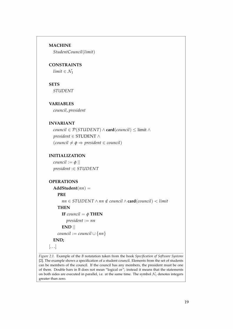
Figure 2.1 contains a sample specification in the B notation. The specification describesa student council with members and a president, and is taken from the book Specificationof Software Systems by Alagar and Periyasamy [2], which cover several different formalnotations.
More in-depth material about specific methods is available in books like Software Specifica-tion Methods by Frappier and Habrias [21], Modeling in Event-B by Abrial [1], and Construct-ing Correct Software by Cooke [17].
18
MACHINEStudentCouncil(limit)
CONSTRAINTSlimit ∈ N1
SETSSTUDENT
VARIABLEScouncil, president
INVARIANTcouncil ∈ P(STUDENT) ∧ card(council) ≤ limit ∧president ∈ STUDENT ∧(council 6= φ⇒ president ∈ council)
INITIALIZATIONcouncil := φ ||president :∈ STUDENT
OPERATIONSAddStudent(nn) =
PREnn ∈ STUDENT ∧ nn /∈ council ∧ card(council) < limit
THENIF council = φ THEN
president := nnEND ||
council := council ∪ {nn}END;
[. . .]
Figure 2.1. Example of the B notatation taken from the book Specification of Software Systems[2]. The example shows a specification of a student council. Elements from the set of studentscan be members of the council. If the council has any members, the president must be oneof them. Double bars in B does not mean “logical or”; instead it means that the statementson both sides are executed in parallel, i.e. at the same time. The symbol N1 denotes integersgreater than zero.
19
3. Functional Safety and ISO 26262
ISO 26262 is a standard about functional safety, which by ISO 26262 is defined as the “ab-sence of unreasonable risk due to hazards caused by malfunctioning behaviour of E/Esystems” [31]. A deeper discussion will not be provided, but ultimately, “unreasonable”boils down to the probability that someone dies due to an hazard caused by an E/E system.
ISO 26262 is a domain specific realisation of the more general purpose standard IEC 61508,which is sometimes informally referred to as “The mother of all [functional] safety stan-dards”. There are also realisations for other industries such as aviation, railway and heavymachinery.
One important difference between ISO 26262 and IEC 61508 is that the latter is written formass-production of electronic components, while ISO 26262 is concerned about the safetyin complete vehicles.
For mass-produced electronic hardware products, it is possible to produce statistics such asmean time to failure, which then can be used to calculate probabilities in a safety situation.Unfortunately, this is much harder to do for a software system; it can be proved to be unsafe,but not the other way around.
Therefore, the importance of being able to make a strong case that a particular systemindeed is safe increases. One way to do so is to have an established process which followsgood development practices, and the approach taken by ISO 26262 is to provide a set ofrequirements regarding the entire development lifecycle. This set of requirements is on afairly detailed level; the entire standard consists of approximately 400 pages.
Overall, different aspects relating to requirements are a large part of the standard. Below isa brief explanation on how the standard makes use of requirements. Note that this is onlya very small part, and that there are lots of other aspects such as testing and verification.
When a system is developed in accordance with the standard, the first thing that is neededis an item definition. This definition must, among other things, contain a description of theitem, assumptions on external system dependencies and a preliminary architecture. Re-quirements or goals that are not safety-related will also be part of the definition.
It is important to note that an item is not the entire vehicle. The size of an item is arbitrary,although larger systems may be more complex to design. On the other hand, a smallersystem may have more external dependencies.
When the item definition is in place, it is used as a basis for a hazard analysis. This analysiswill produce a list of hazardous events, where each event is given an ASIL (Automotive SafetyIntegrity Level). The ASIL is an indication on how dangerous the event is, ranging from Ato D, where D is most dangerous. An event may also be given the value QM which meansthat ASIL-related directives do not apply, and that normal Quality Management is enough.
Each hazardous event is then assigned to a Safety Goal, which is formulated so that when thegoal holds, the event will not occur. The Safety Goal inherits the ASIL of the hazardous eventthat is assigned to it. Multiple events may be allocated to the same goal; if that happens,the Safety Goal inherits the highest ASIL of the set of events assigned to it.
From the Safety Goals, FSRs (Functional Safety Requirement) are derived. This could for ex-ample be done by an Fault Tree Analysis. The FSRs are in turn implemented by TSRs (Tech-nical Safety Requirement). Each TSR can then be implemented by a Software or Hardware
20
Safety Requirement. The last two levels (i.e., hardware and software safety requirements) arehowever outside the scope of this thesis.
Each consecutive step in the process will have defined outputs. These are called work prod-ucts. All the work products from the process are combined into a Safety Case, which togetherwith written argumentation makes a case that the entire item indeed is safe.
Finally, it is worth to mention that ISO 26262 only concerns functional safety. There willbe other requirements and considerations that must be taken into account for the systemdevelopment, and these may be impacted by other standards or regulations.
21

Glossary
Acrolinx IQ A tool succeeding the Scania Checker for the purpose of achiev-ing consistent language in service manuals. 29, 55, 86
boilerplate A template consisting of fixed syntax elements and placehold-ers for attributes. 31, 35, 46, 56, 63, 73–77, 79, 85, 92, 94, 95
CESAR Project An European project with the title “Cost-efficient methods andprocesses for safety relevant embedded systems”. 18, 30, 31, 35,73, 74, 95
domain ontology A domain specific ontology, i.e., a database with concepts andrelations between the concepts. 31, 35, 55, 63, 76, 85, 92, 95
formal methods Development methods with strong mathematical foundationswhich also employ formal notations. 17, 35, 47, 50, 56, 84, 87,88, 91
formal notation Defined by ISO 26262 as a “description technique that has bothits syntax and semantics completely defined”. 44, 47–52, 83, 84,87, 94
functional safety The absence of unacceptable risk to persons due to hazardscaused by defects or bad design in an E/E system. 20, 21, 31,34, 35, 84, 85
GLNQ Predecessor of DODT. 31
informal notation Defined by ISO 26262 as a “description technique that does nothave its syntax completely defined”. 44, 47, 84, 87
ISO 26262 The international standard ISO 26262 “Road vehicles – Func-tional safety”. 13, 14, 20, 21, 23, 29, 32–36, 41–53, 56, 63, 70, 74,79, 83–85, 92, 95
natural language A language used to communicate between native-speaking hu-mans. 16, 17, 31, 44, 46, 48, 52, 54, 67, 68, 73–75, 77, 78, 83–85,87, 88, 91, 92, 94
Requirements Engineering The field of gathering, specifying and managing requirementsduring system development. 16, 30, 34, 52
Scania Checker A web-based tool used at Scania to increase consistence andquality in service manuals. 29, 86
Scania Lexicon A corporate lexicon containing terms that are specific to Scania.29, 35, 55, 63, 67, 86
semantics The meaning of a word or a sentance. 16, 44, 46, 47, 54, 84, 94
semi-formal notation Defined by ISO 26262 as a “description technique whose syntaxis completely defined but whose semantics definition may beincomplete”. 46, 51, 52, 84
23
Software Engineering The field of constructing software systems in an organised way.16, 48
stakeholder A party with an interest in the outcome of a system or project.13, 30, 42, 54
syntax The set of rules defining how a sentence may be formed. 16, 31,44, 46, 47, 54, 55, 65, 74, 84, 92, 94
Systems Engineering The field of constructing entire systems, particularly those thatinclude both software, hardware and humans, in an organisedway. 16, 30, 34, 50
24
Acronyms
ASIL Automotive Safety Integrity Level. 20, 42, 84
CNL Constrained, or Controlled, Natural Language. 46, 54, 83, 88, 92
DODT Domain Ontology Design Tool. 31, 35, 56, 58, 59, 63–65, 67, 69–79, 85, 86, 92, 95
E/E Electrical/Electronic. 13, 20, 34, 35, 83
ECU Electronic Control Unit. 35
FMEA Failure Mode and Effects Analysis. 31
FSR Functional Safety Requirement. 20, 51, 52
OCL Object Constraint Language. 31, 95
OMG Object Management Group. 31, 47
OWL Web Ontology Language. 55, 64, 65, 67
RDM Requirements Definition and Management. 43, 85, 86, 91, 94
SBVR Semantics of Business Vocabulary and Business Rules. 31, 95
SG Safety Goal. 51, 52, 63, 84
TSR Technical Safety Requirement. 20, 51, 52
UML Unified Modeling Language. 31, 47, 64
W3C World Wide Web Consortium. 55
25


Part II:
Related work and method

4. Related work
While no material regarding requirement notations and ambiguity in relation to ISO 26262has been found, there do exist a lot of research and other work that in different ways relateto this thesis. In this chapter, the work this thesis builds on is presented together with otherrelevant material.
4.1 The Scania Lexicon and other language tools
In the early 1990s, Scania started to use a digital catalogue for article numbers and theircorresponding labels. The catalogue was named Termlex, which also contained the sameterms in five different languages. Later on, Termlex was replaced by another application,Termweb, and given the name Scania Lexicon. At that point, the database was also cleanedup, definitions were added to the terms, and terminologists started to actively manage thecontents. Today, Scania Lexicon is the official terminology database for Scania, containingnot only article numbers, but also other terminology. The number of languages has grownfrom 5 to 21, and the Scania Lexicon is used both by engineers and by technical writers.
Starting in the second half of the 1990s, the After Market department at Scania and theDepartment of Linguistics and Philology at Uppsala University did a joint research projectwith the aim to be able to perform machine translation of truck maintenance documen-tation [6, 52]. Part of the project was to develop a constrained natural language titledScaniaSwedish. While the original goal of automated translation was never achieved, theproject resulted in a web based application named Scania Checker. The checker is de-scribed by Almqvist and Sågvall Hein [5] in the following way:
Scania Checker is a language checker for automotive service literature in Swedish. It comprisesa word checker and a grammar checker. A fundamental part of the wordchecker is a lexicaldatabase. [5]
The lexical database makes it easier for the technical writers to use a consistent vocabularyover time and in different documents. By using the lexicon, the Scania Checker is able tohighlight – in different colours – rejected synonyms (red) and unknown terms (yellow). Athird colour, green, is used to highlight grammatical errors. Almqvist and Sågvall Hein [5]also offers insight into how the Scania Checker was fit into the workflow at Scania. Forexample, the Scania Checker allows the writer to submit unknown terms for review andinclusion into the lexical database.
In 2011, work begun to phase out the Scania Checker in order to replace it with a productnamed Acrolinx IQ, which has support for integration directly into office tools like Mi-crosoft Word and Framemaker. Additionally, it can be used to check that a text conformswith a predefined style. The new solution will use the same data that was initially collectedfor the Scania Checker and then refined over the years of continuous usage.
Although the checker is used for writing service manuals within the After Market depart-ment in Scania, there are at least two interesting aspects that relate directly to the field ofsystems development:
29
1. In both cases, it is important that a consistent vocabulary is used between all stake-holders. In fact, the After Market is a stakeholder to the high level system require-ments because some of the information will, at a later stage, be incorporated into theservice manuals.
2. As will be discussed later, using constrained natural languages (CNL) is a potentialapproach for writing better requirements. The knowledge and experience that theAfter Market department have gained in the area of language processing can bevaluable also in other parts of the organisation.
There are of course some differences as well. The biggest one is that there are differentunderlying goals: for After Market, focus would be on automated document generationinto multiple languages, while for system development, the focus would be on usable andunambiguous requirement specifications. For systems requirements, it may be acceptableto have rather terse sentences that not necessarily are what a native speaker is accustomedto. This might, however, not be such a good idea in a service manual with world-widedistribution.
Another difference is that for service manuals, the source language is Swedish. For soft-ware development, the language is mainly English, which also nowadays is the officialcorporate language within Scania.
4.2 The CESAR Project
The CESAR Project is a European project with 55 participating organisations mainly in thetransportation sector. CESAR stands for “Cost-efficient methods and processes for safetyrelevant embedded systems” [14].
According to the project website, “CESAR will bring significant and conclusive innovationsin the two most improvable Systems Engineering disciplines:
Requirements engineering in particular through formalization of multi viewpoint, multi crite-ria and multi level requirements, . . . ” [14]
The focus on Requirements Engineering in the transportation sector makes the CESARProject highly relevant for this thesis. Unfortunately, most of the project deliverables arerestricted to the partner organisations, but two of the deliverables are available for thepublic and contains a wealth of information:
1. The SP2 (Requirements Engineering) report titled Definition and exemplification of RSLand RMM [12]
2. The SP3 (Component Based Development) report titled Survey Report on ModelingLanguages, Components Technologies and Validation Technologies for Real-Time Safety Crit-ical Systems [13]
Additionally, as some of the partners are academic institutions, the CESAR Project has alsoresulted in published research papers. Some of these are covered in the next section.
30
4.3 Domain ontologies and boilerplates
In the context of computer science, ontologies were first described by Thomas Gruber [24]for application in the artificial intelligence field. An ontology can be seen as a databaseof concepts with relations between them, and a domain ontology is an ontology which isspecialised for a certain domain, for example the automotive industry.
In a research paper from 2006, Kaiya and Saeki [37] present a method for how a domain on-tology can be utilised during requirements elicitation (i.e., the gathering of requirements).Two interesting aspects are that when concepts in the requirements are mapped to an on-tology, it becomes possible to a) establish metrics of the requirements quality, and b) detectinconsistencies between the requirements.
Omoronyia et al. [42] extend the work of Kaiya and Saeki by researching how the processof building a domain ontology can be automated. They find that the manual effort can bereduced by importing domain specific documents such as standards and existing require-ment specifications.
As part of the CESAR Project, Stålhane et al. [51] presents a tool, GLNQ, which combinesthe previous work on domain ontologies with the concept of boilerplates. Boilerplateswere introduced by Hull et al. [27] and are predefined templates where certain attributesare inserted at specific placeholders in the text. Boilerplates also have similarities with thelinguistic concept of sentence stems, which are described by Pawley and Syder [43]. Leeb-Lundberg [38] makes use of the sentence stem theory to investigate how students of lawlearn to use specific juridical terms.
Furthermore, Stålhane et al. [51] creates boilerplates based on requirements from the IEC61508 functional safety standard. They also extend the information in the ontology in orderto make it possible to describe potential failure modes for each concept. This allows GLNQto output an FMEA (Failure Mode and Effects Analysis)-like table based on the conceptsthat are actually used in the requirements.
The work on safety analysis is extended in a more recent paper by Stålhane et al. [50] whereGLNQ is superseded by the newer tool DODT (Domain Ontology Design Tool).
Finally, Farfeleder et al. [20] describe in some detail how DODT can be used for ontology-supported requirements elicitation.
4.4 SBVR and OCL
SBVR (Semantics of Business Vocabulary and Business Rules) [55] is an OMG (Object Man-agement Group) specification which “defines the vocabulary and rules for documenting the se-mantics of business vocabularies, business facts, and business rules” [55]. It can be used to con-strain the syntax of a natural language in a way similar to boilerplates.
OCL (Object Constraint Language) [56] is another OMG specification which was primar-ily designed to include formal constraints in UML (Unified Modeling Language) models.Warmer and Kleppe [58] describe how OCL works and presents a vision how it in the fu-ture could be used in a pure Model-Driven Development setting. They also argue that UMLwithout OCL is ambiguous, and that the other way around is meaningless.
There are research related to OCL at the University of Birmingham. For example, Bajwa etal. [7] outline how natural language can be transformed to OCL statements by an interme-diary SBVR step. According to a project website at the same university [57], there is also atool that can transform natural language to the Alloy [4] specification language.
31
4.5 Other thesis projects at Scania
Performed concurrently with this thesis, there were also several other thesis projects atScania that relate to ISO 26262. The one that is most relevant is the thesis by Erlandsson[19], which investigates the changes necessary to bring the existing requirement documentswithin Scania into compliance with ISO 26262. The thesis also contains a more in-depthdiscussion about requirements in general.
32
5. Method
This thesis was performed in a time period corresponding to 20 full time weeks and amount-ing to 30 Swedish university credits. The work was divided into five areas; each performedin parallel, but with varying intensity over time:
I. Understanding Scania
II. Understanding Requirements Engineering
III. Understanding ISO 26262 and Functional Safety
IV. Understanding formal methods
V. Performing a case study
Each area is described in more detail in dedicated sections at the end of this chapter. Ascan be expected, there were also some overlap as well as dependencies between the areas.
Since Scania use Lean or Agile-inspired work processes, it was from the beginning deter-mined that a similar approach would be taken with the thesis project. This was particu-larly suitable since the topics covered in this thesis were new to both Scania and the thesisworker. In practice, this allowed the thesis to change direction as new knowledge was at-tained. As a consequence, the thesis does not cover exactly what was initially thought itwould.
The original idea was to investigate formal methods as a means to achieve requirementsthat could be automatically verified. This included plans for evaluation a number of dif-ferent formal methods in the context of a Scania system, in order to ultimately providerecommendations regarding their fitness for Scania. Additionally, since there is some buzzin the industry as well as academia regarding ADLs (Architecture Description Languages),it was suggested that the thesis should cover the possibility to express requirements in anADL such as AADL or EAST-ADL.
However, it was relatively soon found that an adequate evaluation of several formal meth-ods would require more time than what is possible in a master thesis project. It wouldalso require prior experience with such methods. As for ADLs, they were found to be notapplicable for the higher level requirements. Therefore, focus was shifted towards otherareas.
Nevertheless, the original plans have to some extent influenced the thesis:
a) The objectives have been approached under the assumption that formal methods isa suitable solution to ambiguity, and also a possible means for automatic analysis.
b) Due to the formal approach, and of course also because this is an academic paper, alot of effort has been made for finding exact and agreed upon definitions for conceptsdescribed in the standard.
The report itself was produced in an Agile-inspired manner where focus was on one chap-ter at a time. After completing a chapter and receiving feedback on it, focus was shifted tothe next chapter. This approach was chosen because it was preferred to have fewer parts ofhigh quality rather than many topics with less quality.
In addition to this thesis, there were three other thesis projects at Scania that studied dif-ferent aspects of ISO 26262. Therefore, it was natural and indeed encouraged by the thesis
33
supervisor at Scania that there were interactions and knowledge sharing between the dif-ferent thesis projects as well as other relevant parties within Scania.
Finally, a couple of conferences and seminars on relevant topics were attended.
5.1 Understanding Scania
As was described in the introduction, a previous thesis performed a gap analysis betweenScania and a draft of ISO 26262. This was used as a starting point for both understandingthe environment within Scania and understanding ISO 26262. Other activities consisted ofparticipating in internal meetings, study visits and thesis presentations.
It was also decided that an actual in-vehicle E/E system would be used as reference in orderto have something to relate to when discussing ISO 26262 and other theoretical aspects.This is the same system as was used for the case study.
The system in question is the fuel level display which is responsible for measuring and dis-playing the vehicle fuel level and, if the fuel level falls below a certain threshold, display alow fuel level warning to the driver.
Another decision was to perform the daily work at the Scania R&D offices in Södertälje.
Overall, the above aspects gave insights into how Scania operates. It must, however, bepointed out that Scania is a very large company, and that it therefore would be ridiculousto claim a complete understanding of the entire corporation.
5.2 Understanding Requirements Engineering
Since both ISO 26262 and this thesis is focusing heavily on concepts from RequirementsEngineering, and also because ISO 26262 in general do not explain the rationale betweenthe various directives in the standard, it was necessary to gain an understanding on whatthe literature in the field recommended. In short, this meant that a lot of reading had to bedone in order to get an enough background to be able to relate to the requirements in ISO26262 and other standards.
Many of these books were revisited during the course of the project, and they proved toincrease in value as various insights from the practical work were related to the conceptsdescribed in the books.
5.3 Understanding ISO 26262 and Functional Safety
As ISO 26262 is a standard oriented towards functional safety, it was imperative to gain anunderstanding about this concept. To achieve this, parts of the book Safeware by Leveson[40] were studied. It was early on found that functional safety has ties to Systems Engi-neering, wherefore a book on that topic was studied as well.
In order to understand ISO 26262, all master thesis workers with an interest in the standardparticipated in a study circle. This allowed for discussions where the attendees togethercould get a deeper understanding of the standard than by reading it individually.
34
Although it is not included in this thesis, the author did participate in creating a hazardanalysis for the same system that is used as an example in the case study. This hazardanalysis was done according to the directives in ISO 26262, and contributed much to theunderstanding thereof. The hazard analysis step is particularly important, since it is theinitiation of the safety life-cycle, and the source from which all safety requirements arederived. In order to better understand the possible consequences of a potential systemfailure, some experiments with a real truck were done.
Overall, ISO 26262 is very extensive. The understanding of the standard did mature overtime as different interpretations were discussed and discarded or refined. In some cases,external experiences from the EN 50128 standard for railways and the ISO 9001 were usedin order to better understand ISO 26262.
5.4 Understanding formal methods
As was stated earlier in this chapter, the objectives were approached from the formal meth-ods side, under the assumption that this approach, if no other, would be a viable solutionfor removing ambiguity. Therefore, a lot of effort was put into understanding what formalmethods actually is, and for what problems and domains they are particularly useful for.To gain the desired understanding, both books and research papers were studied. Also,discussions with the reviewer of the thesis at Uppsala University were held, which wereuseful in order to keep on track and find suitable material.
5.5 Performing the case study
In order to provide concrete examples and also show that the results are relevant for Scania,a case study was performed where boilerplates and a domain ontology were applied to anexisting vehicle system. The actual tool used for this is DODT. The technique was chosenfor two reasons:
I. Scania already has a corporate dictionary with domain and company specificterms titled the Scania Lexicon (see Chapter 4) together with personnel to man-age it. The experience and knowledge from the Scania Lexicon can be leveragedif Scania choose to further research the ontology concept. It may even be possibleto use the same platform as the Scania Lexicon.
II. The research papers that are published about DODT and its predecessor GLNQare aligned with functional safety aspects due to collaboration with the CESARProject.
The system the technique was applied to was identified by Scania staff. It was deemedsuitable because:
a) it is relatively small (only 4 ECUs (Electronic Control Unit) are involved),
b) it is not very complex (again, relatively speaking),
c) it is not overly sensitive in regard to intellectual property, and
d) the existing requirement and specification documents are considered representativefor the majority of the E/E systems at Scania.
35

During the case study, care was taken to follow, to the extent it was possible, the workflowprescribed in ISO 26262. The results, and also a more detailed description on how the studywas performed are available in Chapter 9.
36
Part III:
Current and future practices

6. Structure and elements of requirements
This chapter begins with a motivation for why requirements are important for software andsystem development, including some comments on how requirements relate to Agile andLean. This is followed by a compilation of requirements on the requirements themselves,both individually and as a set.
6.1 Why requirements matter
An in-depth discussion on the merits of good requirements and requirements managementis outside the scope of this thesis. However, there are a lot of literature indicating that miss-ing or bad requirements commonly is responsible for late or failed projects. For example,according to Bowen and Hinchey [10], data from NASA shows a strong correlation be-tween project cost overruns and too little time spent on requirements. Glass [22], in hisbook Software Runaways state the following:
Study after study has found that where there is a failure, requirements problems are usuallyfound at the heart of the matter. [22]
In addition to cost overruns, lack of requirements can also lead to harm, including loss oflife:
In an investigation of failed safety-critical systems, one study found nearly 1,100 deaths at-tributable to computer error. Many of these errors stemmed from poor or no specifications,not an incorrect implementation. [10]
Finally, without requirements, it makes no sense to speak about verification or validation,because there is nothing to verify against.
6.2 Using requirements throughout the process
Requirements are not something that should be done early on and subsequently left staticduring the development process. As the work progress downwards in e.g., the V-model,new information will be found which can result in compromises in existing requirements.New requirements may also be discovered during the process that was not though of ini-tially.
After the requirements are written, the next step in the development process is to create anarchitecture or design of the system. Both “architecture” and “design” are words that areused intermixedly and with different meanings. This thesis uses both in the broader senseof establishing a logical or physical structure of the components or parts of a system.
39
Unfortunately, it is not uncommon that the requirements phase is reduced or altogetherignored, because creating a design is perceived as real work, while writing requirementsare not.
Sometimes, it is said that developers do not like requirements because it takes the creativityout of their work. If that is the case, then the requirements are not written correctly. Arequirement should state what the system should do, not how. Overspecification can be asbad as underspecification, because it might restrict the developers from finding the bestpossible solution to the problem.
6.3 Requirements, Lean, and Agile
Some proponents of Agile methods appear to use Agile as an excuse to avoid doing re-quirements at all. The following seems to be a common argument “Since everything mightchange during the process, there is no need for any requirements, since those too willchange.”
However, change does not exclude requirements. As Alexander and Stevens [3] write:
[. . . ] expecting change is not an excuse for not doing the requirements well. The more youfind out about what the users want early on, the less needless change there will be in therequirements, and the less the project will cost. [3]
Agile methods such as Scrum, do make use of requirements. The difference is that it iscalled sprint or product backlog instead of requirements, and that the prioritisation is al-lowed to be volatile.
Agile is also influenced by Lean, and the primary Lean principle is to eliminate waste [44].Without good requirements, the developers have no guidance on what to develop, whichmeans that functionality that is unneeded may be included. This is, by Mary and TomPoppendieck, considered as serious waste:
Eliminating waste is the most fundamental lean principle, the one from which all the otherprinciples follow [. . . ]
It may seem like a good idea to put some extra features into a system just in case they areneeded [. . . ] This may seem harmless, but on the contrary, it is serious waste. Every bit ofcode in the system has to be tracked, compiled, integrated and tested every time the code istouched, and then it has to be maintained for the life of the system. Every bit of code increasescomplexity and is a potential failure point. [44]
As with everything else, there is no method that is best for everything. While the volatilerequirements approach used by Agile methods such as Scrum may be highly suitable foruser interface development, it may not be equally suitable for a safety critical system. Inthe latter case, the impact of a requirements change during the process may be higher. Forexample, changing a key feature of a system could require that a new hazard analysis mustbe performed, and in turn that new safety goals must be added. This would likely affectthe entire architecture, leading to higher costs and delayed delivery.
40
6.4 Properties and attributes of requirements
The difference between a property and an attribute is that a property describe a characteristic,i.e. something that that the requirement is, while an attribute can be said to be somethingthe requirement has, i.e. something that can be attached or annotated to it.
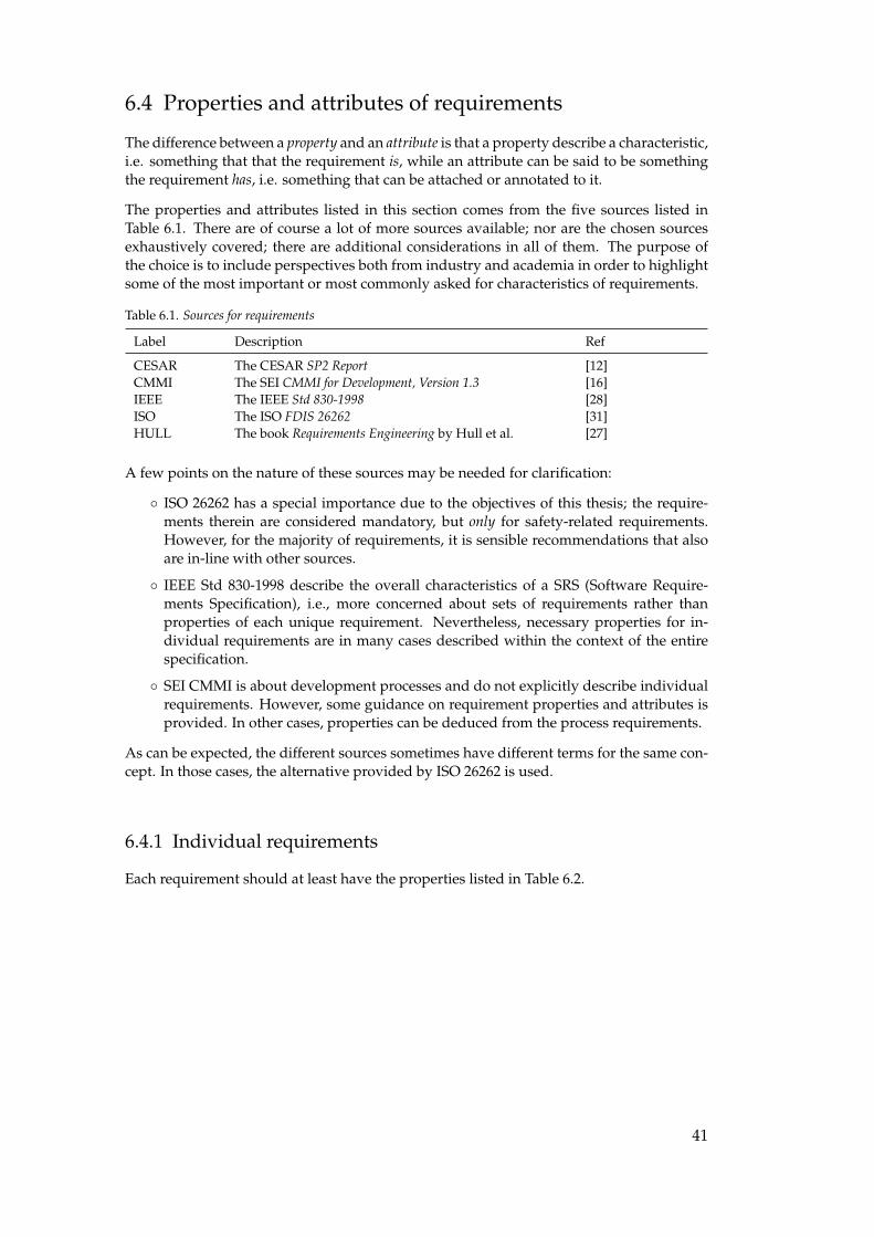
The properties and attributes listed in this section comes from the five sources listed inTable 6.1. There are of course a lot of more sources available; nor are the chosen sourcesexhaustively covered; there are additional considerations in all of them. The purpose ofthe choice is to include perspectives both from industry and academia in order to highlightsome of the most important or most commonly asked for characteristics of requirements.
Table 6.1. Sources for requirements
Label Description Ref
CESAR The CESAR SP2 Report [12]CMMI The SEI CMMI for Development, Version 1.3 [16]IEEE The IEEE Std 830-1998 [28]ISO The ISO FDIS 26262 [31]HULL The book Requirements Engineering by Hull et al. [27]
A few points on the nature of these sources may be needed for clarification:
◦ ISO 26262 has a special importance due to the objectives of this thesis; the require-ments therein are considered mandatory, but only for safety-related requirements.However, for the majority of requirements, it is sensible recommendations that alsoare in-line with other sources.
◦ IEEE Std 830-1998 describe the overall characteristics of a SRS (Software Require-ments Specification), i.e., more concerned about sets of requirements rather thanproperties of each unique requirement. Nevertheless, necessary properties for in-dividual requirements are in many cases described within the context of the entirespecification.
◦ SEI CMMI is about development processes and do not explicitly describe individualrequirements. However, some guidance on requirement properties and attributes isprovided. In other cases, properties can be deduced from the process requirements.
As can be expected, the different sources sometimes have different terms for the same con-cept. In those cases, the alternative provided by ISO 26262 is used.
6.4.1 Individual requirements
Each requirement should at least have the properties listed in Table 6.2.
41

Table 6.2. Properties of individual requirement
Property Description Sources
Unambiguous The requirement has only one interpretation. CESAR, IEEE, ISOComprehensible All stakeholders are able to understand the require-
ment.ISO
Atomic The requirement cannot be split into two or more re-quirements.
HULL, IEEE, ISO
Consistent The requirement does not contradict itself. ISOFeasible The requirement can be implemented within the con-
straints of the project or organisation.CESAR, CMMI, HULL,ISO
Verifiable It is known how to, and practically possible, to verifythat the produced artefact meets the requirement.
CESAR, CMMI, HULL,IEEE, ISO
The properties are not enough it themselves; it is also necessary to be able to attach addi-tional information, referred to as attributes, to each requirement. The following attributesare recommended by one or several sources, or required for safety requirements by ISO26262:
Table 6.3. Individual requirement attributes
Attribute Description Sources
Unique identifier The requirement has an unique identifier. CMMI, HULL, ISOSafety requirement If it is a safety requirement, it is flagged as such. ISOStatus The requirement has a status, for example proposed or
approved.CMMI, ISO
ASIL If it is a safety requirement, it must have an ASIL. ISOImportance The importance of the requirement, e.g., optional or es-
sentialCMMI, HULL, IEEE
Stability A measure on how likely the requirement is to change. IEEE
6.4.2 Sets of requirements
A set of requirements can for example be a document such as the SRS described in IEEEStd 830-1998. In this thesis, however, it will be used mainly in the context of an item asdescribed by ISO 26262. In other words, the set of requirements will be all the requirementsthat pertain to a particular item. The required characteristics for a set of requirements arelisted in Table 6.4
42
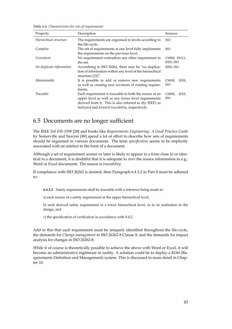
Table 6.4. Characteristics for sets of requirements
Property Description Sources
Hierarchical structure The requirements are organised in levels according tothe life-cycle.
ISO
Complete The set of requirements at one level fully implementsthe requirements on the previous level.
ISO
Consistent No requirement contradicts any other requirement inthe set.
CMMI, HULL,IEEE, ISO
No duplicate information Accordning to ISO 26262, there may be “no duplica-tion of information within any level of the hierarchicalstructure [31]”.
IEEE, ISO
Maintainable It is possible to add or remove new requirementsas well as creating new revisions of existing require-ments.
CMMI, IEEE,ISO
Traceable Each requirement is traceable to both the source at anupper level as well as any lower level requirementsderived from it. This is also referred to (by IEEE) asbackward and forward traceability, respectively.
CMMI, IEEE,ISO
6.5 Documents are no longer sufficient
The IEEE Std 830-1998 [28] and books like Requirements Engineering: A Good Practice Guideby Somerville and Sawyer [49] spend a lot of effort to describe how sets of requirementsshould be organised in various documents. The term specification seems to be implicitlyassociated with an artefact in the form of a document.
Although a set of requirement sooner or later is likely to appear in a form close to or iden-tical to a document, it is doubtful that it is adequate to store the source information in e.g.,Word or Excel documents. The reason is traceability.
If compliance with ISO 26262 is desired, then Paragraph 6.4.3.2 in Part 8 must be adheredto:
6.4.3.2 Safety requirements shall be traceable with a reference being made to:
a) each source of a safety requirement at the upper hierarchical level,
b) each derived safety requirement at a lower hierarchical level, or to its realisation in thedesign, and
c) the specification of verification in accordance with 9.4.2.
Add to this that each requirement must be uniquely identified throughout the life-cycle,the demands for Change management in ISO 26262-8 Clause 8, and the demands for impactanalysis for changes in ISO 26262-8.
While it of course is theoretically possible to achieve the above with Word or Excel, it willbecome an administrative nightmare in reality. A solution could be to deploy a RDM (Re-quirements Definition and Management) system. This is discussed in more detail in Chap-ter 10.
43
7. Notations for requirements
Requirements can be specified in varying degrees of formality. They can also be repre-sented in different forms such as text, symbols, or graphics.
Note well: the formality and the form of representation are orthogonal. Mathemathicalsymbols can be used informally, and normal words can be used in a highly formal manner.This distinction made, it is however more common that mathematical symbols are used inmore formal notations. Graphics is used in all levels of formality, from a quick drawing ona whiteboard during a meeting, to a completely formalised state machine.
Different degrees of formality and forms of representation can also be combined. Eachmethod or combination thereof may be more or less suitable for a particular organisation,and the suitability of a given method can also vary between the various phases in thedevelopment process.
7.1 Levels of formality
The degree of formality for a given notation can be divided into three levels: informal, semi-formal and formal. The difference is to what extent the syntax and semantics is defined. Asthe degree of formality increase, the ambiguity typically decreases. The definition in thebeginning of each subsection below is taken from ISO 26262-1 [31].
7.1.1 Informal notation
Definition:
description technique that does not have its syntax completely defined
EXAMPLE Description in figure or diagram.
NOTE An incomplete syntax definition implies that the semantics are also not completelydefined. [31]
The most common informal notation is probably natural language (commonly referred toas NL), i.e. English or Swedish. There is one major advantage with NL, namely that ev-eryone can read and understand it. On the other hand, natural language is inherently am-biguous [28], which contradicts the proposition that everyone can understand it: it wouldprobably be more correct to say that everyone have their own understanding of it.
Take for example the following requirement from the requirements document for the exist-ing fuel level display system:
44
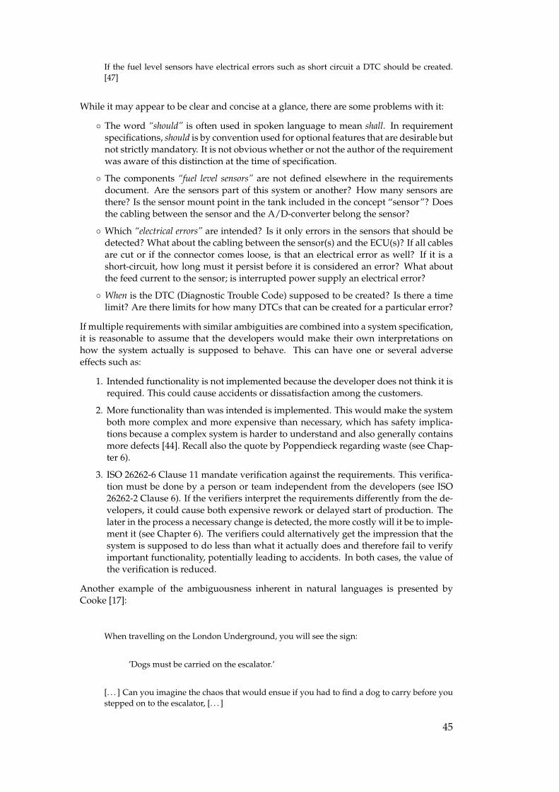
If the fuel level sensors have electrical errors such as short circuit a DTC should be created.[47]
While it may appear to be clear and concise at a glance, there are some problems with it:
◦ The word “should” is often used in spoken language to mean shall. In requirementspecifications, should is by convention used for optional features that are desirable butnot strictly mandatory. It is not obvious whether or not the author of the requirementwas aware of this distinction at the time of specification.
◦ The components “fuel level sensors” are not defined elsewhere in the requirementsdocument. Are the sensors part of this system or another? How many sensors arethere? Is the sensor mount point in the tank included in the concept “sensor”? Doesthe cabling between the sensor and the A/D-converter belong the sensor?
◦ Which “electrical errors” are intended? Is it only errors in the sensors that should bedetected? What about the cabling between the sensor(s) and the ECU(s)? If all cablesare cut or if the connector comes loose, is that an electrical error as well? If it is ashort-circuit, how long must it persist before it is considered an error? What aboutthe feed current to the sensor; is interrupted power supply an electrical error?
◦ When is the DTC (Diagnostic Trouble Code) supposed to be created? Is there a timelimit? Are there limits for how many DTCs that can be created for a particular error?
If multiple requirements with similar ambiguities are combined into a system specification,it is reasonable to assume that the developers would make their own interpretations onhow the system actually is supposed to behave. This can have one or several adverseeffects such as:
1. Intended functionality is not implemented because the developer does not think it isrequired. This could cause accidents or dissatisfaction among the customers.
2. More functionality than was intended is implemented. This would make the systemboth more complex and more expensive than necessary, which has safety implica-tions because a complex system is harder to understand and also generally containsmore defects [44]. Recall also the quote by Poppendieck regarding waste (see Chap-ter 6).
3. ISO 26262-6 Clause 11 mandate verification against the requirements. This verifica-tion must be done by a person or team independent from the developers (see ISO26262-2 Clause 6). If the verifiers interpret the requirements differently from the de-velopers, it could cause both expensive rework or delayed start of production. Thelater in the process a necessary change is detected, the more costly will it be to imple-ment it (see Chapter 6). The verifiers could alternatively get the impression that thesystem is supposed to do less than what it actually does and therefore fail to verifyimportant functionality, potentially leading to accidents. In both cases, the value ofthe verification is reduced.
Another example of the ambiguousness inherent in natural languages is presented byCooke [17]:
When travelling on the London Underground, you will see the sign:
’Dogs must be carried on the escalator.’
[. . . ] Can you imagine the chaos that would ensue if you had to find a dog to carry before youstepped on to the escalator, [. . . ]
45
Although the above may be seen as a toy problem, it is a good example of how easy it isto include unstated assumptions in natural language, assumptions that may not be sharedby all stakeholders. To be able to write good requirements in natural language, discipline,previous experience from requirements and solid language skills are needed, but even thatmay not be enough to avoid ambiguity.
7.1.2 Semi-formal notation
Definition:
description technique whose syntax is completely defined but whose semantics definition canbe incomplete
EXAMPLE System Analysis and Design Techniques (SADT); Unified Modeling Language(UML). [31]
ISO 26262 does not define “syntax”, and much less what a “completely defined” syntaxis. In the linguistic tradition, syntax is usually defined in a similar manner as was statedin Chapter 2: “The syntax of a language is a system of grammar laying out rules about how toproduce or recognize grammatical phrases or sentences.” [26].
What, then, is “completely defined” syntax? Drawing inspiration from the field of formallanguages and also the book Concepts of programming languages [48], this thesis will use thefollowing definition:
DEF: The syntax of a language L is completely defined if and only if, for any string S, it can be deter-mined without doubt whether or not S is part of L.
Using the above definition, most programming languages have completely defined syntax.It is also possible to impose strict enough rules on a natural languages to comply with theabove definition. Such languages are intermixedly referred to as Controlled or ConstrainedNatural Language. Both are abbreviated as CNL. A CNL can also be less restricted than thedefinition above and still be referred to as CNL. One such example is ScaniaSwedish whichwas described in Chapter 4.
An example of a CNL, which is targeted directly against requirements, is the concept ofboilerplates. As was described in Chapter 4, a boilerplate can be seen as a template con-taining fixed syntax elements and attribute placeholders. The following two boilerplatestatements
While <operational condition>the <system> shall <action>
have <operational condition>, <system>, and <action> as attributes, and can for examplebe combined into
While <the vehicle fuel level is less than the low fuel level threshold> the <fuel level displaysystem> shall <present the low fuel level warning to the driver>
The advantage with semi-formal notations is that the complete syntax can limit the varia-tion of the expressed requirements, which could force the requirements to be formulated in
46
a more concise and consistent manner. Care must however be taken so that the expressive-ness not is reduced too much – it must still be possible and also easy enough to convey thedesired meaning.
The disadvantage is the lack of completely defined semantics. There is therefore still arisk that different individuals will make disparate interpretations. Graphical notations arenot an exception. Consider the well-known adage “one picture says more than a thousandwords” in context of ambiguity: a single requirement consisting of a thousand words couldeasily have more than one interpretation. As Jackson [32] puts it:
The cure is to be very careful when you write a description in any language, and to be twice ascareful again if it’s a graphic language. [32]
UML (Unified Modeling Language), which is given as an example by ISO 26262, meritssome additional commentary since it is well-known and used for various purposes bymany IT professionals. UML is an OMG (Object Management Group) standard. The cur-rent official version (2.3) consists of two different specifications, the Infrastructure [53] andthe Superstructure [54], which together amounts to about 1000 pages of text mixed with fig-ures. This extensiveness may be due to the history of UML. Bowen and Hinchey [10] makethe following remark:
Another caveat to using UML is that it essentially standardizes several existing and emerginggraphical notations for system specification [. . . ] Some of these are there for good reason;others, because they had support from particular quarters. [10]
Since there are 14 diagram types – of different origins and therefore lacking common designprinciples – it can be quite difficult to determine whether a given diagram comply with theUML specification or not. Although it is certainly possible to read the specification itselfand try to compare it with the diagram, it is hard to get a clear picture of what is allowedand what is not. The reason for this is that the specification is written in a way that makesit hard to be sure in what context a given element may be used. The situation is not helpedby the fact that is allowed to include parts, or the whole, of a diagram into a diagram of adifferent type.
Consequently, if it is hard to be certain whether a specific diagram conforms to the syntaxor not, there is a risk that UML, for all practical purposes, is no better than an informalnotation .
7.1.3 Formal notation
Definition:
description technique that has both its syntax and semantics completely defined
EXAMPLE Z (Zed); NuSMV (symbolic model checker); Prototype Verification System (PVS);Vienna Development Method (VDM). [31]
ISO 26262 does not further define completely defined semantics, but based on the term “de-scription technique” and the provided examples, the standard seems to equate formal no-tations with formal methods (see Chapter 2). While the two terms are closely related, this
47

thesis makes the distinction that a formal notation is the notation used by a correspondingformal method. By implication, completely defined semantics then means that the notationcan be transformed into a mathematical system where proofs can be performed.
There is yet another related term that needs clarification, namely formal specification,which is here defined as the artefact created when a formal notation is deployed to specifya system. In other words, a formal specification contains formal notation, and may havebeen produced using a formal method or technique.
The main advantage with formal notations is that there, by the ISO 26262 definition, canbe no ambiguity. This makes it possible to establish, without doubt, whether a system con-forms to its specification or not, without arguments or confusion on what the requirementsactually mean. This also makes such requirements suitable for legal contracts with externalsuppliers.
On the other hand, it is commonly held that formal notations are hard to understand andrequires training before they can be used:
One disadvantage in the use of such languages is the length of time required to learn them.Also, many non-technical users find them unintelligible. [28]
Both points are valid. However, as was mentioned earlier, being able to formulate goodrequirements in natural language is far from easy and requires both training and experi-ence. Similarly, it is unreasonable to expect a developer to produce quality code in newprogramming language without prior training. The same should apply for requirementsspecification languages, formal or otherwise.
Of course, someone outside the field of Software Engineering should not be required orexpected to understand formal notations. Therefore, an accompanying translation into nat-ural language is needed:
[. . . ] someone must fully explain formal specifications so that they are understandable to bothnonspecialists and those working on the specification after its initial development. [10]
Producing a natural language version from a formal notation also have other advantages:
This effort is worthwhile, since our experience has shown that documents produced from aformal specification can be more comprehensible, more accurate, shorter, and more useful thaninformal specifications. [25]
Although the above quote is about manual transformation, it should also be possible toautomate this process since, after all, the notation is unambiguous. Each statement couldthen also be output in different languages, depending on capabilities of the tool used forthe task. A further study about automatic natural language generation is outside the scopeof this thesis.
The crucial question is whether formal methods are worth the effort. It is important to beaware that formal methods are not “all or nothing”; rather, they can be employed to differ-ent degrees in various phases. For example, Bowen and Hinchey presents three differentlevels, where each subsequent level builds on the previous one. This is shown in Table 7.1.
Since this thesis mainly is concerned with requirements, focus will be on level 0. Thisis also the level where most organisations stand to gain the majority of benefits if they notalready are using formal methods. The two subsequent levels can of course provide further
48
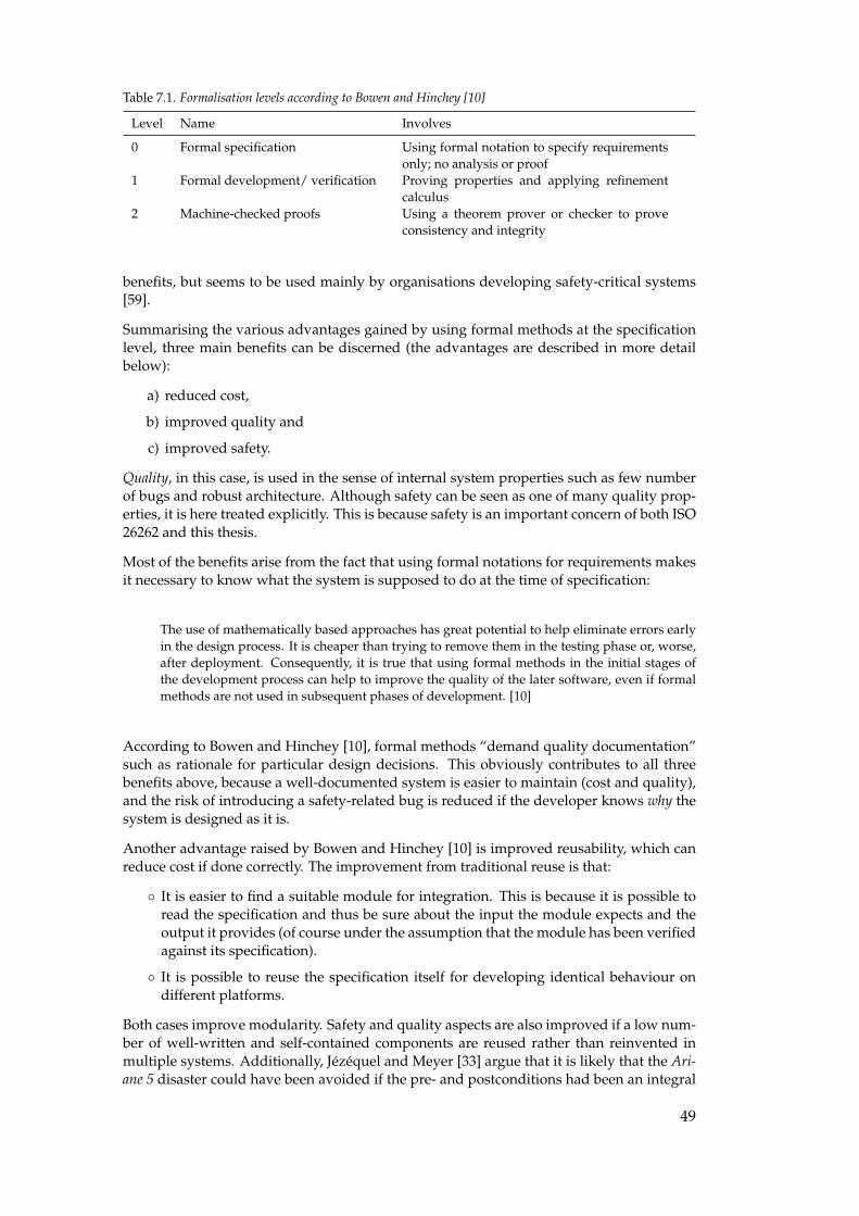
Table 7.1. Formalisation levels according to Bowen and Hinchey [10]
Level Name Involves
0 Formal specification Using formal notation to specify requirementsonly; no analysis or proof
1 Formal development/ verification Proving properties and applying refinementcalculus
2 Machine-checked proofs Using a theorem prover or checker to proveconsistency and integrity
benefits, but seems to be used mainly by organisations developing safety-critical systems[59].
Summarising the various advantages gained by using formal methods at the specificationlevel, three main benefits can be discerned (the advantages are described in more detailbelow):
a) reduced cost,
b) improved quality and
c) improved safety.
Quality, in this case, is used in the sense of internal system properties such as few numberof bugs and robust architecture. Although safety can be seen as one of many quality prop-erties, it is here treated explicitly. This is because safety is an important concern of both ISO26262 and this thesis.
Most of the benefits arise from the fact that using formal notations for requirements makesit necessary to know what the system is supposed to do at the time of specification:
The use of mathematically based approaches has great potential to help eliminate errors earlyin the design process. It is cheaper than trying to remove them in the testing phase or, worse,after deployment. Consequently, it is true that using formal methods in the initial stages ofthe development process can help to improve the quality of the later software, even if formalmethods are not used in subsequent phases of development. [10]
According to Bowen and Hinchey [10], formal methods “demand quality documentation”such as rationale for particular design decisions. This obviously contributes to all threebenefits above, because a well-documented system is easier to maintain (cost and quality),and the risk of introducing a safety-related bug is reduced if the developer knows why thesystem is designed as it is.
Another advantage raised by Bowen and Hinchey [10] is improved reusability, which canreduce cost if done correctly. The improvement from traditional reuse is that:
◦ It is easier to find a suitable module for integration. This is because it is possible toread the specification and thus be sure about the input the module expects and theoutput it provides (of course under the assumption that the module has been verifiedagainst its specification).
◦ It is possible to reuse the specification itself for developing identical behaviour ondifferent platforms.
Both cases improve modularity. Safety and quality aspects are also improved if a low num-ber of well-written and self-contained components are reused rather than reinvented inmultiple systems. Additionally, Jézéquel and Meyer [33] argue that it is likely that the Ari-ane 5 disaster could have been avoided if the pre- and postconditions had been an integral
49
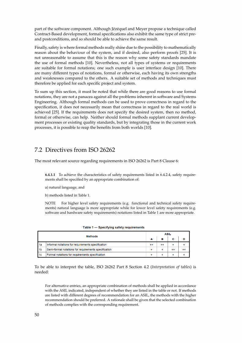
part of the software component. Although Jézéquel and Meyer propose a technique calledContract-Based development, formal specifications also exhibit the same type of strict pre-and postconditions, and so should be able to achieve the same result.
Finally, safety is where formal methods really shine due to the possibility to mathematicallyreason about the behaviour of the system, and if desired, also perform proofs [25]. It isnot unreasonable to assume that this is the reason why some safety standards mandatethe use of formal methods [10]. Nevertheless, not all types of systems or requirementsare suitable for formal notations; one such example is user interface design [10]. Thereare many different types of notations, formal or otherwise, each having its own strengthsand weaknesses compared to the others. A suitable set of methods and techniques musttherefore be applied for each specific project and system.
To sum up this section, it must be noted that while there are good reasons to use formalnotations, they are not a panacea against all the problems inherent in software and SystemsEngineering. Although formal methods can be used to prove correctness in regard to thespecification, it does not necessarily mean that correctness in regard to the real world isachieved [25]. If the requirements does not specify the desired system, then no method,formal or otherwise, can help. Neither should formal methods supplant current develop-ment processes or existing quality standards, but by integrating those in the current workprocesses, it is possible to reap the benefits from both worlds [10].
7.2 Directives from ISO 26262
The most relevant source regarding requirements in ISO 26262 is Part 8 Clause 6:
6.4.1.1 To achieve the characteristics of safety requirements listed in 6.4.2.4, safety require-ments shall be specified by an appropriate combination of:
a) natural language, and
b) methods listed in Table 1.
NOTE For higher level safety requirements (e.g. functional and technical safety require-ments) natural language is more appropriate while for lower level safety requirements (e.g.software and hardware safety requirements) notations listed in Table 1 are more appropriate.
To be able to interpret the table, ISO 26262 Part 8 Section 4.2 (Interpretation of tables) isneeded:
For alternative entries, an appropriate combination of methods shall be applied in accordancewith the ASIL indicated, independent of whether they are listed in the table or not. If methodsare listed with different degrees of recommendation for an ASIL, the methods with the higherrecommendation should be preferred. A rationale shall be given that the selected combinationof methods complies with the corresponding requirement.
50
NOTE A rationale based on the methods listed in the table is sufficient. However, thisdoes not imply a bias for or against methods not listed in the table.
For each method, the degree of recommendation to use the corresponding method dependson the ASIL and is categorized as follows:
− ++ indicates that the method is highly recommended for the identified ASIL;− + indicates that the method is recommended for the identified ASIL;− o indicates that the method has no recommendation for or against its usage for the identified
ASIL.
The above is slightly ambiguous. It both states that there is "no bias for or against" anyof the methods, and that methods with higher recommendations "should be preferred". Acommon interpretation at Scania is that methods marked with "++" must be performed,while anything less can be done if so is desired, but it is not strictly necessary for compli-ance.
An interesting issue arise when Table 1 in the cited clause is studied in detail. For ASIL Cand D, by the given interpretation, semi-formal notation is to be used. Would it be equallyacceptable to go one step further and instead use formal notations? A formal notationfulfils, according to the definition in ISO 26262, everything that a semi-formal notationdoes. The difference is that a formal notation also has completely defined semantics. Itseems reasonable that an organisation should be allowed to use a formal notation as areplacement of a semi-formal notation because:
a) Semi-formal notations are subsets of formal notations according to the definitionsgiven in ISO 26262.
b) A formal representation can, if so desired, easily be transformed into a semi-formalone. The easiest way, but perhaps not the most sensible, would be to simply statethat the formal portion of the notation is not taken into account.
c) It seems counterproductive to restrict the usage of the most exact methods when thegoal is to improve functional safety.
This does of course not mean that such a substitution should be done in every case; thekey point is that it is possible to do so. The above points could be sufficient as a rationaleaccording to the standard, but the decision will ultimately be in the hands of the assessor.
As was stated in the objectives in Chapter 1, this thesis is primarily concerned with higherlevel requirements. Therefore, a more detailed analysis about the directives regarding thesetypes of requirements is merited. Consider again the note from Paragraph 6.4.1.1 in ISO26262-8:
NOTE For higher level safety requirements (e.g. functional and technical safety require-ments) natural language is more appropriate [. . . ]
Although the note only lists FSRs (Functional Safety Requirement) and TSRs (TechnicalSafety Requirement), it can be assumed that SGs (Safety Goal) also belong to the categoryhigher level requirements. This assumption can be motivated because a) it is not specifiedelsewhere in the standard how SGs should be written, and b) the following note from ISO26262 Part 3, Paragraph 7.4.4.3:
NOTE Safety goals are top-level safety requirements for the item [. . . ]
51
At this stage, the following observation can be made:
ISO 26262 has a bias for specifying SGs, FSRs and TSRs in natural language.
To complicate matters, this bias contradicts another part of ISO 26262-8 Clause 6, namelyParagraph 6.4.2.4:
6.4.2.4 Safety requirements shall have the following characteristics:
a) unambiguous and comprehensible,
NOTE 1 A requirement is unambiguous if there is common understanding of the mean-ing of the requirement.
NOTE 2 A requirement is comprehensible if the reader at an adjacent abstraction level (i.e.either the stakeholder or the consumer of that requirement) understands its meaning.
The contradiction lies in the inherent ambiguousness in natural languages, which was il-lustrated in the previous section. Formulated in other words, ISO 26262 states that it isappropriate to use an inherently ambiguous notation in order to write unambiguous require-ments.
No rationale for the preference for natural language is given, but from the note aboutcomprehensibility and also Requirements Engineering literature such as [3], it could beassumed that the main reason is that SGs, FSRs and TSRs should be readable without requir-ing training in formal or semi-formal notations. Recall, however, that that use of formalnotation should come with associated natural language narrative, so they are by no meansexclusive.
To further complicate matters, a requirement written in a semi-formal CNL could very wellbe indistinguishable from a natural language when it is seen by the reader; the constraintsare imposed mainly on the writer. It could be argued that such an approach is more appro-priate than (informal) natural language due to the inherent ambiguity in the latter.
From a compliance perspective, it would depend on how literal-minded the assessor wouldbe, and whether he or she would interpret the directives to mean the the resulting require-ments, or the process of writing them.
Another observation that is worth to point out explicitly is the following:
ISO 26262 does not state that natural language has to be the only representation for the higher-levelrequirements.
As was described earlier, there are many benefits associated with using formal methodsfor requirements specification. If such notations are used together with natural languageversions (i.e. different versions exist for an individual requirement), it must be decidedand communicated which version that has precedence. Due to the preference towardsnatural language in ISO 26262, the interpretation could be that the NL version should takeprecedence. However, Bowen and Hinchey [9] advocate the opposite:
If there is any discrepancy, the formal specification takes precedence because it is the moreexplicit of the two descriptions. [9]
It is also easier to test against a more precise requirement, which means that verifica-tion testing might be done against the formal version. If that is the case, it makes addi-tional sense to let that version have precedence. Nevertheless, doing so could risk non-
52
compliance with ISO 26262, even though the motivation behind the standard is to increasesafety in the systems that are to be developed.
53
8. Semantics and domain knowledge
8.1 The need for semantics
As was mentioned in Chapter 7, requirements can be specified in constrained natural lan-guage CNL. Depending on the syntax definition, such a CNL may also be semi-formal.While this can be an improvement to (informal) natural language, it is not necessarilyenough for achieving high quality requirements. Consider the following boilerplate re-quirement (which arguably could fall in the category of a semi-formal CNL):
While <the vehicle fuel level> is less than the <low fuel level threshold> the <fuel level displaysystem> shall <present> <the low fuel level warning> to <the driver>
The improvement over natural language comes from the imposed overall structure due toa limited syntax; it is clear that something is supposed to occur while a certain conditionholds. However, the same type of problems with ambiguity as was shown in Chapter 7still exist. For example, what exactly is the vehicle fuel level?
◦ Is it the actual fuel level in the tanks, or is it the usable fuel level? If the latter, is theusable fuel level identical to the fuel that can actually be extracted from the tank, orcould usable also mean fuel that it is not mixed with too much water?
◦ What does level mean? Does it have a unit? Is it a volume? Is it the ratio betweentwo volumes, e.g., the ratio between the current fuel volume and the maximum tankvolume?
This list with questions could go on and on for each individual concept in the require-ment. Although it might be seen as academic nitpicking, it is the very type of questionsthat must be answered in order to build a system. If the meaning is not made explicit inthe requirements, there is a risk that the developer(s) could make another interpretationthan the stakeholders, which in turn can lead to one or more adverse effects as outlined inChapter 7.
A second problem arise when various automatic processing of the requirements is consid-ered. Such processing could for example be automated consistency analysis or machinetranslation. Take the word “driver”; it could be replaced by an arbitrary string like “happi-ness”. It is still syntactically correct but it does not make much sense. Even more challeng-ing, it could be a word like “seagull”, which could make sense, but is very implausible to doso in the context of a fuel level display.
To overcome the above challenges, information about the semantics must somehow beincluded in the requirements.
8.2 Improving communication
A first step for solving the problem with ambiguous concepts could be to include a glossaryin the requirements document. In this way, the reader can look up terms that he or she isunfamiliar with. This practice is recommended by IEEE [28] as well as literature [49]. Thereare however some problems with this approach:
54
1. A reader might not always look up concepts that he or she is familiar with, thusmissing that the author in fact has an altogether different interpretation of it.
2. A concept might change meaning over time, but not become updated in every doc-ument it is used in, thus causingdiscrepancies between the written documents andthe institutional knowledge.
The importance of achieving a common understanding of a concept between stakeholdersand developers cannot be stressed enough. What is needed is some sort of knowledge basewhich both writers and readers of the requirements have readily access to. Such a knowl-edge base could exist as a stand-alone lexicon, but it could also be integrated into toolssupporting the writing of documents. Ideally, it would be integrated with any informationmanagement tool used throughout the system life-cycle.
An example of a stand-alone knowledge base is the Scania Lexicon which was covered inChapter 4. The same information is also used by the Acrolinx IQ product which providesintegration with writing tools such as Word and Framemaker.
8.3 Towards automated reasoning
A lexicon is however not enough for allowing automated reasoning. Even if the syntaxis made strict to the degree that only words existing in the lexicon may be inserted into arequirement, a computer system will still not be able to detect words in the lexicon that donot make sense in the given context. The below requirement would be perfectly acceptableby such a system as each concept is taken from the Scania Lexicon:
While <the fuel level> is less than <the gearbox> the <bumper> shall activate <the directionindicator>
Obviously, a lexicon-based approach is not sufficient to ensure useful requirements in itself.If a computer is to be able to analyse a requirement, there must also exist relations betweenthe concepts. One way to achieve this is to use domain ontologies, which were introducedin Chapter 4.
Ontologies can for example be specified in OWL (Web Ontology Language) [60], which isa W3C (World Wide Web Consortium) specification. OWL ontologies are built upon threebasic notions:
◦ Axioms, which are statements or propositions of basic knowledge that are either trueor false.
◦ Entities, also referred to as concepts, that define the objects that are described.
◦ Expressions, also referred to as relations, which connects the entities (or concepts).
A reader that is familiar with Object Oriented Design (OOD) will find similarities in OWL;for example, a concept has a correlation to a class, and there is also a subclass-axiom avail-able. There are also important differences; in OOD, it would probably be considered poordesign to create two identical classes, and then somehow mark those as identical. How-ever, this is a very useful feature in an ontology, because it makes it possible to mark oneof the concepts as deprecated. This is useful in a lexicon where there are different terms forthe same thing, but it is desirable to use only one of them.
If a sufficiently detailed ontology exist, a requirements analysis tool could be “aware” thatthe fuel level display system is related to a user concept, and more specifically to a special-isation driver, but not to “happiness” or “seagulls”. If the ontology is also combined with
55
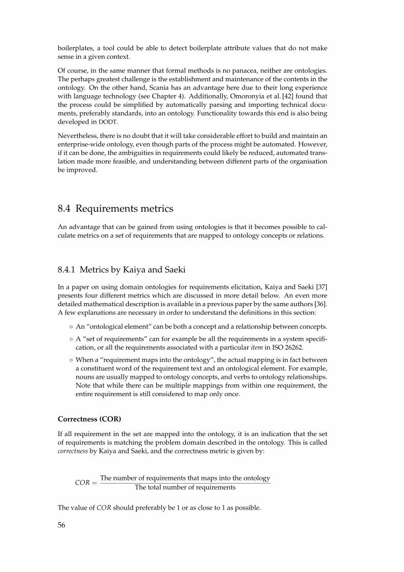
boilerplates, a tool could be able to detect boilerplate attribute values that do not makesense in a given context.
Of course, in the same manner that formal methods is no panacea, neither are ontologies.The perhaps greatest challenge is the establishment and maintenance of the contents in theontology. On the other hand, Scania has an advantage here due to their long experiencewith language technology (see Chapter 4). Additionally, Omoronyia et al. [42] found thatthe process could be simplified by automatically parsing and importing technical docu-ments, preferably standards, into an ontology. Functionality towards this end is also beingdeveloped in DODT.
Nevertheless, there is no doubt that it will take considerable effort to build and maintain anenterprise-wide ontology, even though parts of the process might be automated. However,if it can be done, the ambiguities in requirements could likely be reduced, automated trans-lation made more feasible, and understanding between different parts of the organisationbe improved.
8.4 Requirements metrics
An advantage that can be gained from using ontologies is that it becomes possible to cal-culate metrics on a set of requirements that are mapped to ontology concepts or relations.
8.4.1 Metrics by Kaiya and Saeki
In a paper on using domain ontologies for requirements elicitation, Kaiya and Saeki [37]presents four different metrics which are discussed in more detail below. An even moredetailed mathematical description is available in a previous paper by the same authors [36].A few explanations are necessary in order to understand the definitions in this section:
◦ An “ontological element” can be both a concept and a relationship between concepts.
◦ A “set of requirements” can for example be all the requirements in a system specifi-cation, or all the requirements associated with a particular item in ISO 26262.
◦ When a “requirement maps into the ontology”, the actual mapping is in fact betweena constituent word of the requirement text and an ontological element. For example,nouns are usually mapped to ontology concepts, and verbs to ontology relationships.Note that while there can be multiple mappings from within one requirement, theentire requirement is still considered to map only once.
Correctness (COR)
If all requirement in the set are mapped into the ontology, it is an indication that the setof requirements is matching the problem domain described in the ontology. This is calledcorrectness by Kaiya and Saeki, and the correctness metric is given by:
COR =The number of requirements that maps into the ontology
The total number of requirements
The value of COR should preferably be 1 or as close to 1 as possible.
56
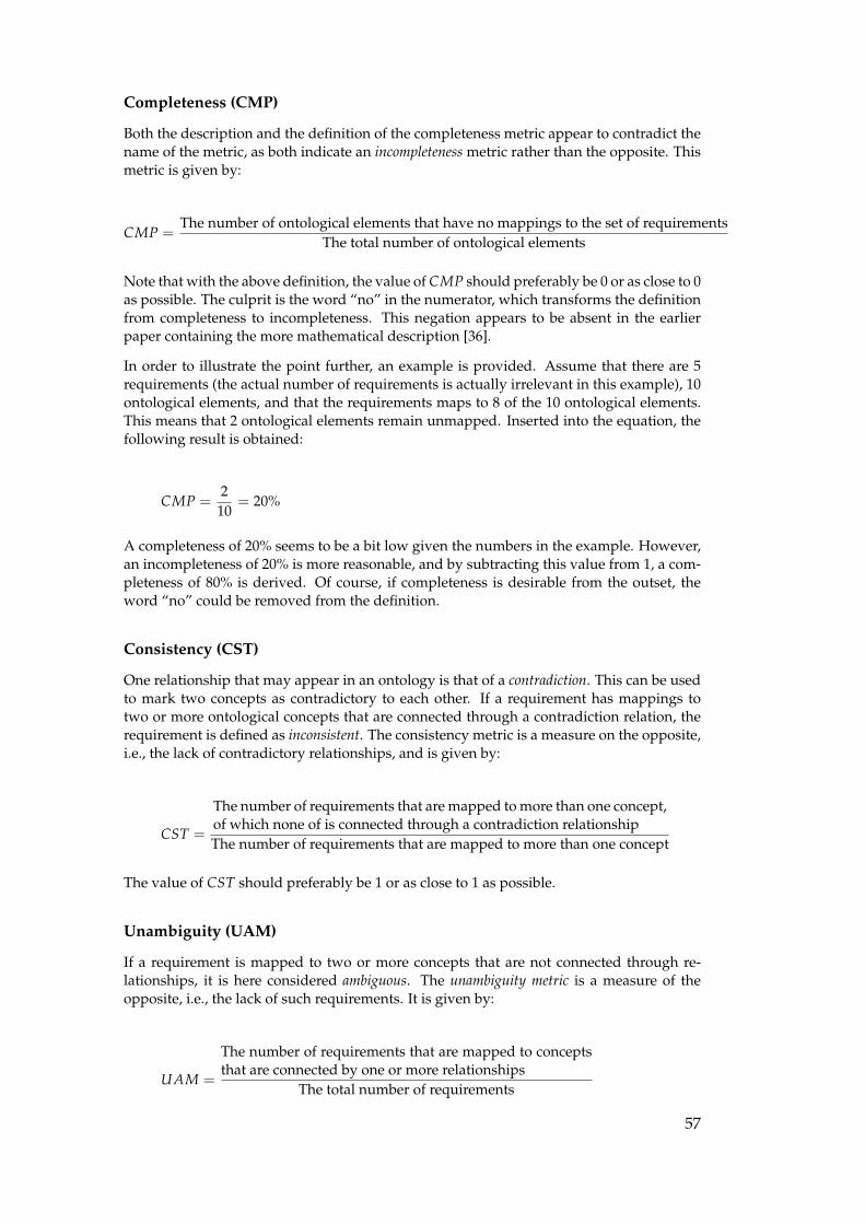
Completeness (CMP)
Both the description and the definition of the completeness metric appear to contradict thename of the metric, as both indicate an incompleteness metric rather than the opposite. Thismetric is given by:
CMP =The number of ontological elements that have no mappings to the set of requirements
The total number of ontological elements
Note that with the above definition, the value of CMP should preferably be 0 or as close to 0as possible. The culprit is the word “no” in the numerator, which transforms the definitionfrom completeness to incompleteness. This negation appears to be absent in the earlierpaper containing the more mathematical description [36].
In order to illustrate the point further, an example is provided. Assume that there are 5requirements (the actual number of requirements is actually irrelevant in this example), 10ontological elements, and that the requirements maps to 8 of the 10 ontological elements.This means that 2 ontological elements remain unmapped. Inserted into the equation, thefollowing result is obtained:
CMP =2
10= 20%
A completeness of 20% seems to be a bit low given the numbers in the example. However,an incompleteness of 20% is more reasonable, and by subtracting this value from 1, a com-pleteness of 80% is derived. Of course, if completeness is desirable from the outset, theword “no” could be removed from the definition.
Consistency (CST)
One relationship that may appear in an ontology is that of a contradiction. This can be usedto mark two concepts as contradictory to each other. If a requirement has mappings totwo or more ontological concepts that are connected through a contradiction relation, therequirement is defined as inconsistent. The consistency metric is a measure on the opposite,i.e., the lack of contradictory relationships, and is given by:
CST =
The number of requirements that are mapped to more than one concept,of which none of is connected through a contradiction relationshipThe number of requirements that are mapped to more than one concept
The value of CST should preferably be 1 or as close to 1 as possible.
Unambiguity (UAM)
If a requirement is mapped to two or more concepts that are not connected through re-lationships, it is here considered ambiguous. The unambiguity metric is a measure of theopposite, i.e., the lack of such requirements. It is given by:
UAM =
The number of requirements that are mapped to conceptsthat are connected by one or more relationships
The total number of requirements
57
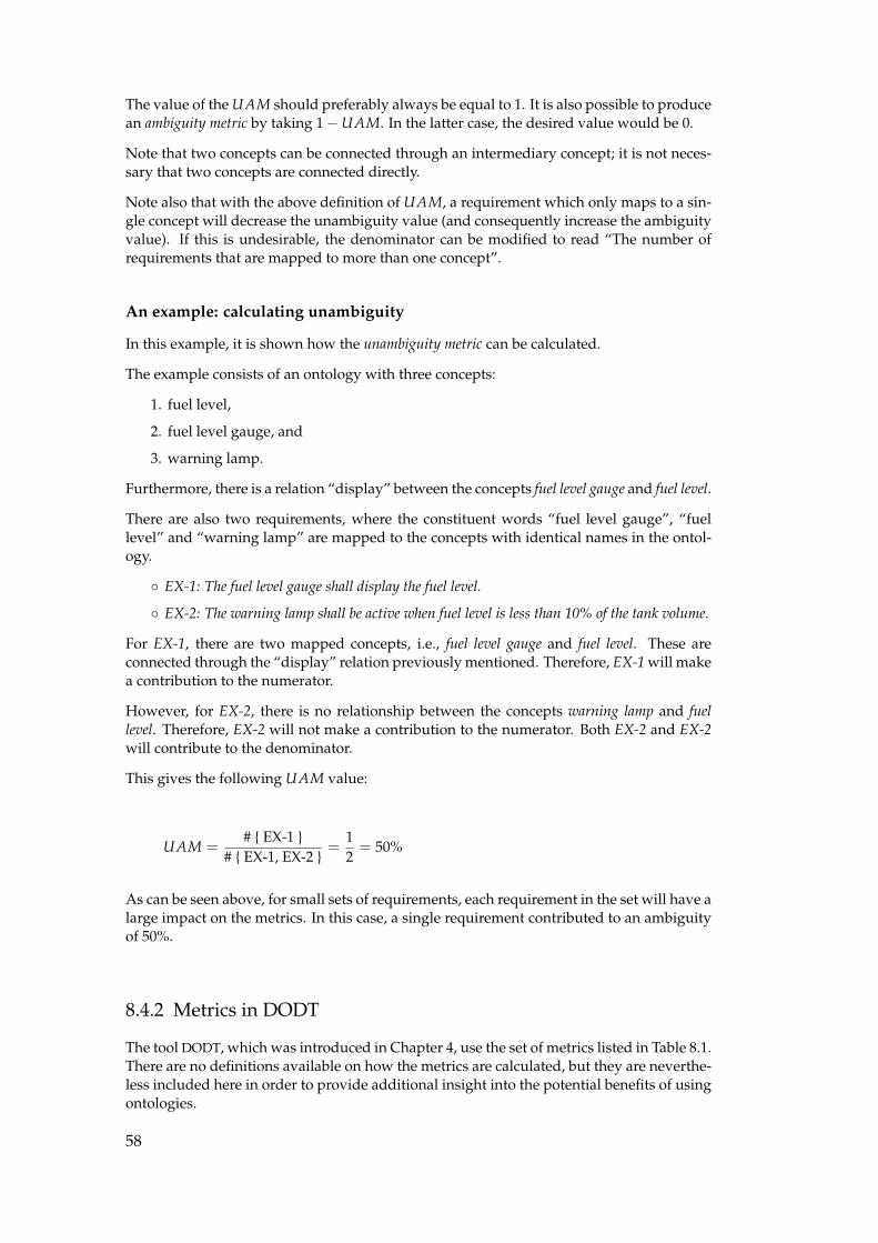
The value of the UAM should preferably always be equal to 1. It is also possible to producean ambiguity metric by taking 1−UAM. In the latter case, the desired value would be 0.
Note that two concepts can be connected through an intermediary concept; it is not neces-sary that two concepts are connected directly.
Note also that with the above definition of UAM, a requirement which only maps to a sin-gle concept will decrease the unambiguity value (and consequently increase the ambiguityvalue). If this is undesirable, the denominator can be modified to read “The number ofrequirements that are mapped to more than one concept”.
An example: calculating unambiguity
In this example, it is shown how the unambiguity metric can be calculated.
The example consists of an ontology with three concepts:
1. fuel level,
2. fuel level gauge, and
3. warning lamp.
Furthermore, there is a relation “display” between the concepts fuel level gauge and fuel level.
There are also two requirements, where the constituent words “fuel level gauge”, “fuellevel” and “warning lamp” are mapped to the concepts with identical names in the ontol-ogy.
◦ EX-1: The fuel level gauge shall display the fuel level.
◦ EX-2: The warning lamp shall be active when fuel level is less than 10% of the tank volume.
For EX-1, there are two mapped concepts, i.e., fuel level gauge and fuel level. These areconnected through the “display” relation previously mentioned. Therefore, EX-1 will makea contribution to the numerator.
However, for EX-2, there is no relationship between the concepts warning lamp and fuellevel. Therefore, EX-2 will not make a contribution to the numerator. Both EX-2 and EX-2will contribute to the denominator.
This gives the following UAM value:
UAM =# { EX-1 }
# { EX-1, EX-2 }=
12= 50%
As can be seen above, for small sets of requirements, each requirement in the set will have alarge impact on the metrics. In this case, a single requirement contributed to an ambiguityof 50%.
8.4.2 Metrics in DODT
The tool DODT, which was introduced in Chapter 4, use the set of metrics listed in Table 8.1.There are no definitions available on how the metrics are calculated, but they are neverthe-less included here in order to provide additional insight into the potential benefits of usingontologies.
58
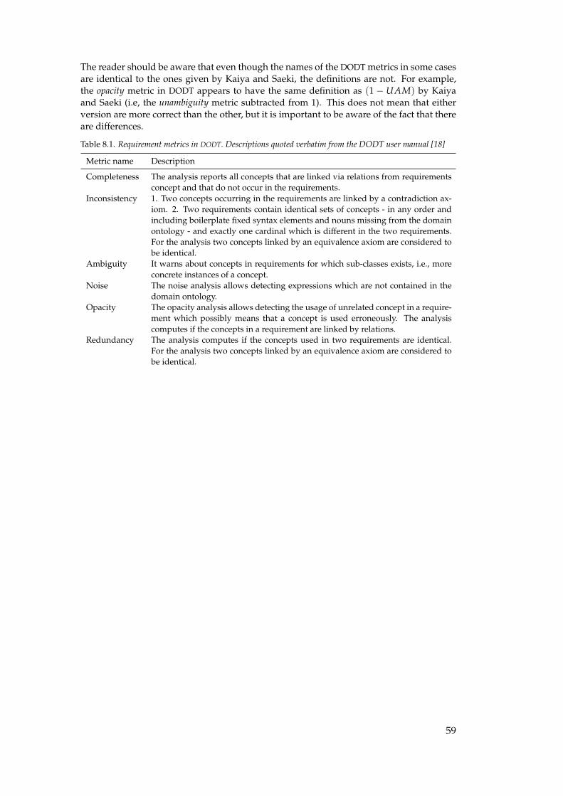
The reader should be aware that even though the names of the DODT metrics in some casesare identical to the ones given by Kaiya and Saeki, the definitions are not. For example,the opacity metric in DODT appears to have the same definition as (1− UAM) by Kaiyaand Saeki (i.e, the unambiguity metric subtracted from 1). This does not mean that eitherversion are more correct than the other, but it is important to be aware of the fact that thereare differences.
Table 8.1. Requirement metrics in DODT. Descriptions quoted verbatim from the DODT user manual [18]
Metric name Description
Completeness The analysis reports all concepts that are linked via relations from requirementsconcept and that do not occur in the requirements.
Inconsistency 1. Two concepts occurring in the requirements are linked by a contradiction ax-iom. 2. Two requirements contain identical sets of concepts - in any order andincluding boilerplate fixed syntax elements and nouns missing from the domainontology - and exactly one cardinal which is different in the two requirements.For the analysis two concepts linked by an equivalence axiom are considered tobe identical.
Ambiguity It warns about concepts in requirements for which sub-classes exists, i.e., moreconcrete instances of a concept.
Noise The noise analysis allows detecting expressions which are not contained in thedomain ontology.
Opacity The opacity analysis allows detecting the usage of unrelated concept in a require-ment which possibly means that a concept is used erroneously. The analysiscomputes if the concepts in a requirement are linked by relations.
Redundancy The analysis computes if the concepts used in two requirements are identical.For the analysis two concepts linked by an equivalence axiom are considered tobe identical.
59

Part IV:
Case study

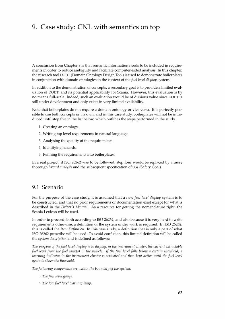
9. Case study: CNL with semantics on top
A conclusion from Chapter 8 is that semantic information needs to be included in require-ments in order to reduce ambiguity and facilitate computer-aided analysis. In this chapter,the research tool DODT (Domain Ontology Design Tool) is used to demonstrate boilerplatesin conjunction with domain ontologies in the context of the fuel level display system.
In addition to the demonstration of concepts, a secondary goal is to provide a limited eval-uation of DODT, and its potential applicability for Scania. However, this evaluation is byno means full-scale. Indeed, such an evaluation would be of dubious value since DODT isstill under development and only exists in very limited availability.
Note that boilerplates do not require a domain ontology or vice versa. It is perfectly pos-sible to use both concepts on its own, and in this case study, boilerplates will not be intro-duced until step five in the list below, which outlines the steps performed in the study.
1. Creating an ontology.
2. Writing top level requirements in natural language.
3. Analysing the quality of the requirements.
4. Identifying hazards.
5. Refining the requirements into boilerplates.
In a real project, if ISO 26262 was to be followed, step four would be replaced by a morethorough hazard analysis and the subsequent specification of SGs (Safety Goal).
9.1 Scenario
For the purpose of the case study, it is assumed that a new fuel level display system is tobe constructed, and that no prior requirements or documentation exist except for what isdescribed in the Driver’s Manual. As a resource for getting the nomenclature right, theScania Lexicon will be used.
In order to proceed, both according to ISO 26262, and also because it is very hard to writerequirements otherwise, a definition of the system under work is required. In ISO 26262,this is called the Item Definition. In this case study, a definition that is only a part of whatISO 26262 prescribe will be used. To avoid confusion, this limited definition will be calledthe system description and is defined as follows:
The purpose of the fuel level display is to display, in the instrument cluster, the current extractablefuel level from the fuel tank(s) in the vehicle. If the fuel level falls below a certain threshold, awarning indicator in the instrument cluster is activated and then kept active until the fuel levelagain is above the threshold.
The following components are within the boundary of the system:
◦ The fuel level gauge.
◦ The low fuel level warning lamp.
63
◦ Any sensors used to measure the fuel level.
◦ Any cabling connecting the components.
◦ Any software necessary to process and display the information.
◦ Any hardware necessary to run the required software.
9.2 Using DODT
9.2.1 Creating an ontology
To be able to use the analysis capabilities of the DODT tool, an ontology is required. Theontology is represented in OWL. DODT has an built-in editor for creating and editing OWLontologies, but it is also possible to import and export OWL data files.
For the purpose of the case study, a single ontology was used, but it is also possible tosplit the ontology into different parts. For example, Farfeleder et al. [20] found it desirableto place non-domain specific measurement units like seconds and kilograms in a separateontology for reuse in other domains. Another example of a more general ontology is Word-Net [41], which contains words and relations from the English language. It is of course alsopossible to use multiple ontologies internally; this could for example be done at enterprise,division, and product level.
Creating an information model
The first step was to manually review the Driver’s Manual in order to identify conceptsapplicable to the stakeholders for the purpose of building an information model. Informationmodels are frequently used at Scania to model both system and organisational aspects. Inthis case, the information model was made as a starting point for the subsequent ontologycreation. The information model is depicted in Figure 9.2
Note that the fuel level concept has been refined with a subclass extractable fuel level to reflectthe domain knowledge that not necessarily all fuel in a tank can be extracted. This a prioriknowledge was also stated in the system description.
Creating the ontology
The information model was manually translated to an ontology by using the built-in ed-itor in DODT (see Figure 9.1). A UML representation of the initial ontology based on theinformation model is available in Figure 9.3.
64
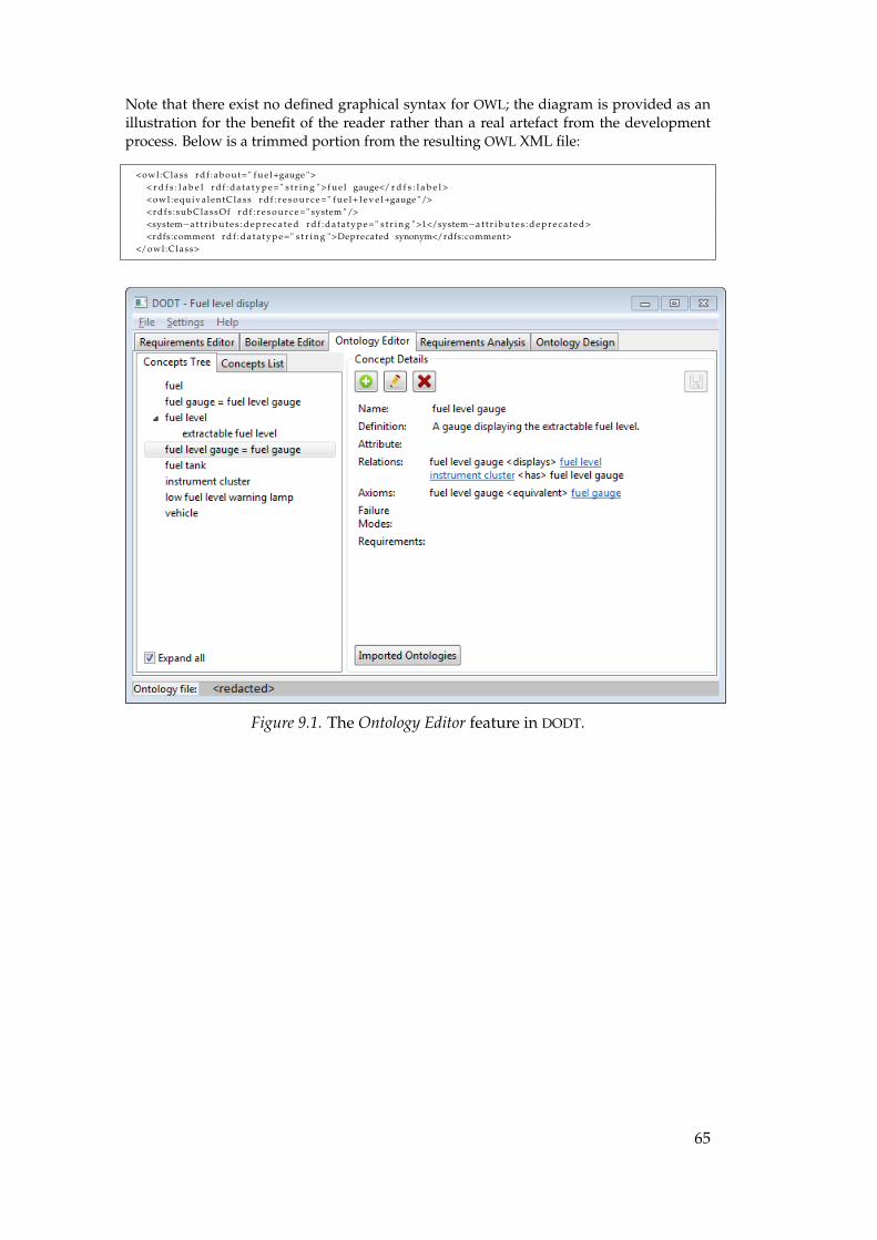
Note that there exist no defined graphical syntax for OWL; the diagram is provided as anillustration for the benefit of the reader rather than a real artefact from the developmentprocess. Below is a trimmed portion from the resulting OWL XML file:
<owl :Class r d f : a b o u t=" f u e l +gauge ">< r d f s : l a b e l r d f : d a t a t y p e =" s t r i n g "> f u e l gauge</ r d f s : l a b e l ><owl :equiva lentClass r d f : r e s o u r c e =" f u e l + l e v e l +gauge "/><rdfs : subClassOf r d f : r e s o u r c e =" system "/><system−a t t r i b u t e s : d e p r e c a t e d r d f : d a t a t y p e =" s t r i n g ">1</system−a t t r i b u t e s : d e p r e c a t e d ><rdfs:comment r d f : d a t a t y p e =" s t r i n g ">Deprecated synonym</rdfs:comment>
</owl :Class>
Figure 9.1. The Ontology Editor feature in DODT.
65
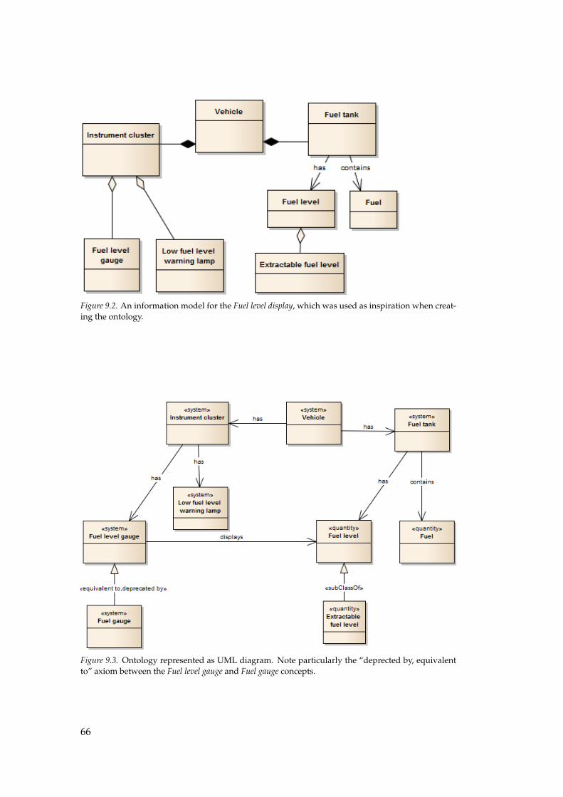
Figure 9.2. An information model for the Fuel level display, which was used as inspiration when creat-ing the ontology.
Figure 9.3. Ontology represented as UML diagram. Note particularly the “deprected by, equivalentto” axiom between the Fuel level gauge and Fuel gauge concepts.
66
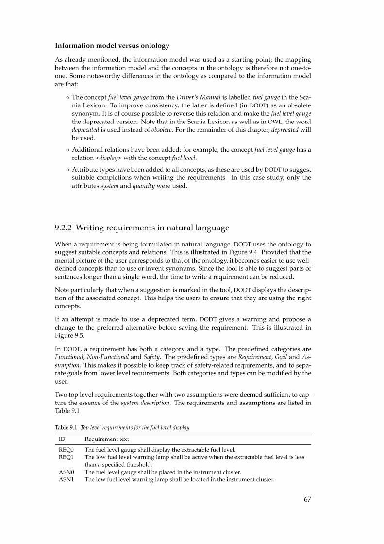
Information model versus ontology
As already mentioned, the information model was used as a starting point; the mappingbetween the information model and the concepts in the ontology is therefore not one-to-one. Some noteworthy differences in the ontology as compared to the information modelare that:
◦ The concept fuel level gauge from the Driver’s Manual is labelled fuel gauge in the Sca-nia Lexicon. To improve consistency, the latter is defined (in DODT) as an obsoletesynonym. It is of course possible to reverse this relation and make the fuel level gaugethe deprecated version. Note that in the Scania Lexicon as well as in OWL, the worddeprecated is used instead of obsolete. For the remainder of this chapter, deprecated willbe used.
◦ Additional relations have been added: for example, the concept fuel level gauge has arelation <display> with the concept fuel level.
◦ Attribute types have been added to all concepts, as these are used by DODT to suggestsuitable completions when writing the requirements. In this case study, only theattributes system and quantity were used.
9.2.2 Writing requirements in natural language
When a requirement is being formulated in natural language, DODT uses the ontology tosuggest suitable concepts and relations. This is illustrated in Figure 9.4. Provided that themental picture of the user corresponds to that of the ontology, it becomes easier to use well-defined concepts than to use or invent synonyms. Since the tool is able to suggest parts ofsentences longer than a single word, the time to write a requirement can be reduced.
Note particularly that when a suggestion is marked in the tool, DODT displays the descrip-tion of the associated concept. This helps the users to ensure that they are using the rightconcepts.
If an attempt is made to use a deprecated term, DODT gives a warning and propose achange to the preferred alternative before saving the requirement. This is illustrated inFigure 9.5.
In DODT, a requirement has both a category and a type. The predefined categories areFunctional, Non-Functional and Safety. The predefined types are Requirement, Goal and As-sumption. This makes it possible to keep track of safety-related requirements, and to sepa-rate goals from lower level requirements. Both categories and types can be modified by theuser.
Two top level requirements together with two assumptions were deemed sufficient to cap-ture the essence of the system description. The requirements and assumptions are listed inTable 9.1
Table 9.1. Top level requirements for the fuel level display
ID Requirement text
REQ0 The fuel level gauge shall display the extractable fuel level.REQ1 The low fuel level warning lamp shall be active when the extractable fuel level is less
than a specified threshold.ASN0 The fuel level gauge shall be placed in the instrument cluster.ASN1 The low fuel level warning lamp shall be located in the instrument cluster.
67
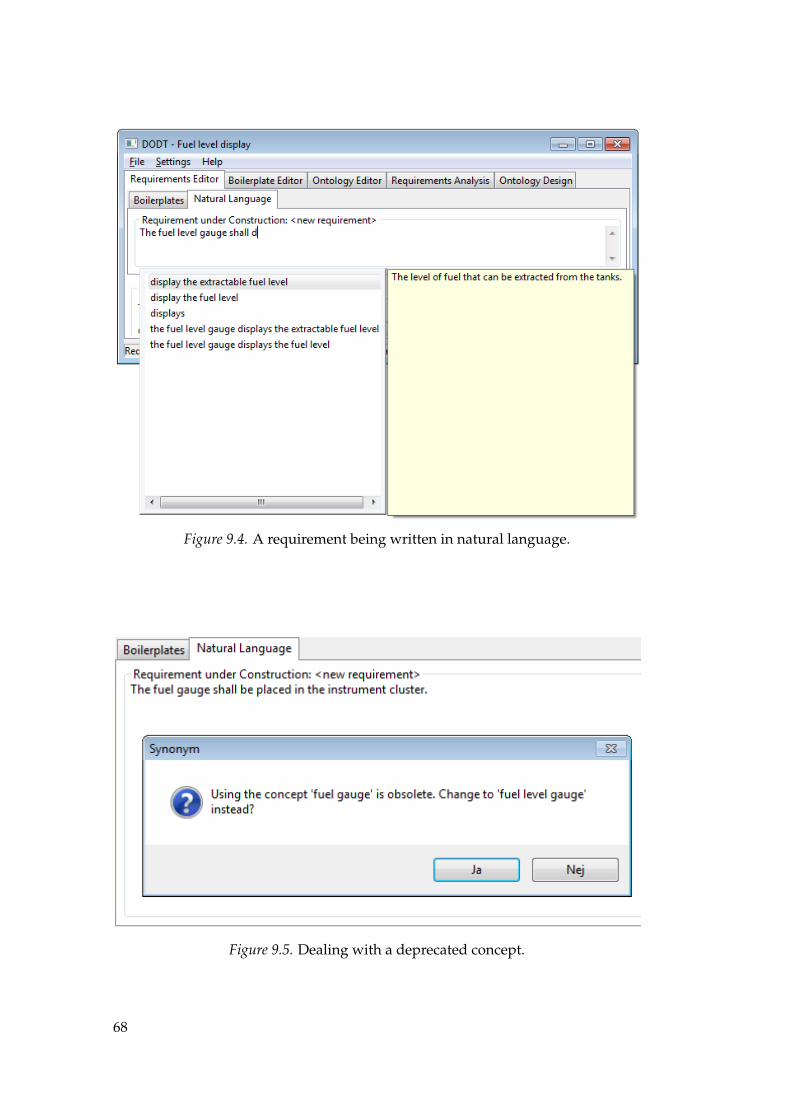
Figure 9.4. A requirement being written in natural language.
Figure 9.5. Dealing with a deprecated concept.
68
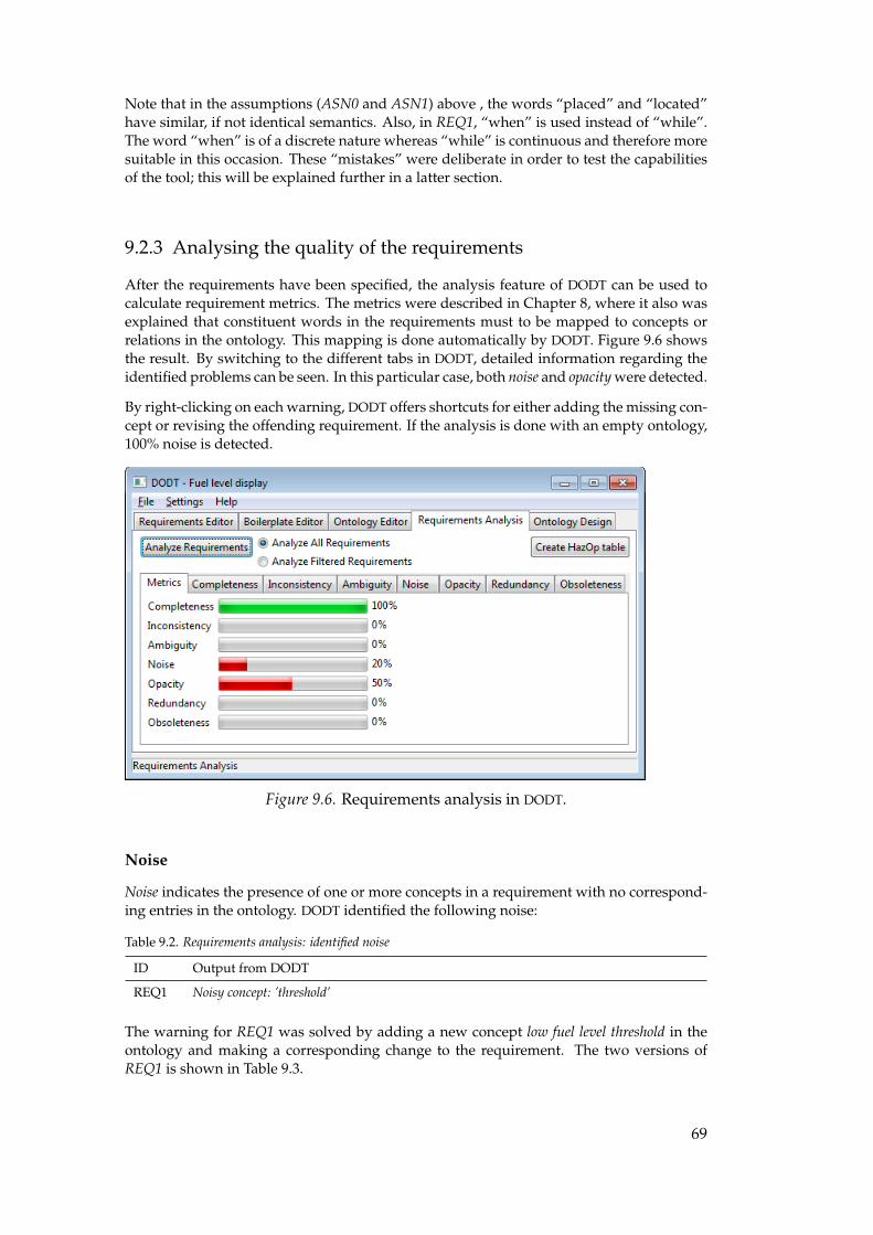
Note that in the assumptions (ASN0 and ASN1) above , the words “placed” and “located”have similar, if not identical semantics. Also, in REQ1, “when” is used instead of “while”.The word “when” is of a discrete nature whereas “while” is continuous and therefore moresuitable in this occasion. These “mistakes” were deliberate in order to test the capabilitiesof the tool; this will be explained further in a latter section.
9.2.3 Analysing the quality of the requirements
After the requirements have been specified, the analysis feature of DODT can be used tocalculate requirement metrics. The metrics were described in Chapter 8, where it also wasexplained that constituent words in the requirements must to be mapped to concepts orrelations in the ontology. This mapping is done automatically by DODT. Figure 9.6 showsthe result. By switching to the different tabs in DODT, detailed information regarding theidentified problems can be seen. In this particular case, both noise and opacity were detected.
By right-clicking on each warning, DODT offers shortcuts for either adding the missing con-cept or revising the offending requirement. If the analysis is done with an empty ontology,100% noise is detected.
Figure 9.6. Requirements analysis in DODT.
Noise
Noise indicates the presence of one or more concepts in a requirement with no correspond-ing entries in the ontology. DODT identified the following noise:
Table 9.2. Requirements analysis: identified noise
ID Output from DODT
REQ1 Noisy concept: ’threshold’
The warning for REQ1 was solved by adding a new concept low fuel level threshold in theontology and making a corresponding change to the requirement. The two versions ofREQ1 is shown in Table 9.3.
69
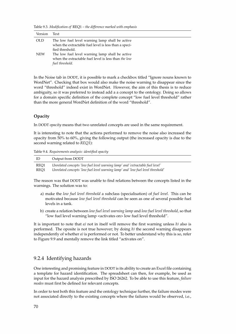
Table 9.3. Modification of REQ1 – the difference marked with emphasis
Version Text
OLD The low fuel level warning lamp shall be activewhen the extractable fuel level is less than a speci-fied threshold.
NEW The low fuel level warning lamp shall be activewhen the extractable fuel level is less than the lowfuel threshold.
In the Noise tab in DODT, it is possible to mark a checkbox titled “Ignore nouns known toWordNet”. Checking that box would also make the noise warning to disappear since theword “threshold” indeed exist in WordNet. However, the aim of this thesis is to reduceambiguity, so it was preferred to instead add a a concept to the ontology. Doing so allowsfor a domain specific definition of the complete concept “low fuel level threshold” ratherthan the more general WordNet definition of the word “threshold”.
Opacity
In DODT opacity means that two unrelated concepts are used in the same requirement.
It is interesting to note that the actions performed to remove the noise also increased theopacity from 50% to 60%, giving the following output (the increased opacity is due to thesecond warning related to REQ1):
Table 9.4. Requirements analysis: identified opacity
ID Output from DODT
REQ1 Unrelated concepts ’low fuel level warning lamp’ and ’extractable fuel level’REQ1 Unrelated concepts ’low fuel level warning lamp’ and ’low fuel level threshold’
The reason was that DODT was unable to find relations between the concepts listed in thewarnings. The solution was to:
a) make the low fuel level threshold a subclass (specialisation) of fuel level. This can bemotivated because low fuel level threshold can be seen as one of several possible fuellevels in a tank.
b) create a relation between low fuel level warning lamp and low fuel level threshold, so that“low fuel level warning lamp <activates on> low fuel level threshold”.
It is important to note that a) not in itself will remove the first warning unless b) also isperformed. The oposite is not true however; by doing b) the second warning disappearsindependently of whether a) is performed or not. To better understand why this is so, referto Figure 9.9 and mentally remove the link titled “activates on”.
9.2.4 Identifying hazards
One interesting and promising feature in DODT is its ability to create an Excel file containinga template for hazard identification. The spreadsheet can then, for example, be used asinput for the hazard analysis prescribed by ISO 26262. To be able to use this feature, failuremodes must first be defined for relevant concepts.
In order to test both this feature and the ontology technique further, the failure modes werenot associated directly to the existing concepts where the failures would be observed, i.e.,
70
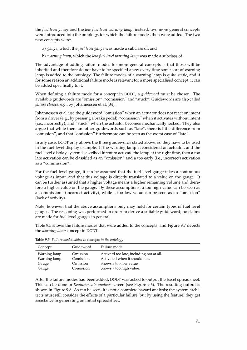
the fuel level gauge and the low fuel level warning lamp; instead, two more general conceptswere introduced into the ontology, for which the failure modes then were added. The twonew concepts were:
a) gauge, which the fuel level gauge was made a subclass of, and
b) warning lamp, which the low fuel level warning lamp was made a subclass of.
The advantage of adding failure modes for more general concepts is that those will beinherited and therefore do not have to be specified anew every time some sort of warninglamp is added to the ontology. The failure modes of a warning lamp is quite static, and iffor some reason an additional failure mode is relevant for a more specialised concept, it canbe added specifically to it.
When defining a failure mode for a concept in DODT, a guideword must be chosen. Theavailable guidewords are “omission”, “comission” and “stuck”. Guidewords are also calledfailure classes, e.g., by Johannessen et al. [34].
Johannessen et al. use the guideword “omission” when an actuator does not react on intentfrom a driver (e.g., by pressing a brake pedal), “comission” when it activates without intent(i.e., incorrectly), and “stuck” when the actuator becomes mechanically locked. They alsoargue that while there are other guidewords such as “late”, there is little difference from“omission”, and that “omission” furthermore can be seen as the worst case of “late”.
In any case, DODT only allows the three guidewords stated above, so they have to be usedin the fuel level display example. If the warning lamp is considered an actuator, and thefuel level display system is ascribed intent to activate the lamp at the right time, then a toolate activation can be classified as an “omission” and a too early (i.e., incorrect) activationas a “commission”.
For the fuel level gauge, it can be assumed that the fuel level gauge takes a continuousvoltage as input, and that this voltage is directly translated to a value on the gauge. Itcan be further assumed that a higher voltage means a higher remaining volume and there-fore a higher value on the gauge. By these assumptions, a too high value can be seen asa“commission” (incorrect activity), while a too low value can be seen as an “omission”(lack of activity).
Note, however, that the above assumptions only may hold for certain types of fuel levelgauges. The reasoning was performed in order to derive a suitable guideword; no claimsare made for fuel level gauges in general.
Table 9.5 shows the failure modes that were added to the concepts, and Figure 9.7 depictsthe warning lamp concept in DODT.
Table 9.5. Failure modes added to concepts in the ontology
Concept Guideword Failure mode
Warning lamp Omission Activatd too late, including not at all.Warning lamp Comission Activated when it should not.Gauge Omission Shows a too low value.Gauge Comission Shows a too high value.
After the failure modes had been added, DODT was asked to output the Excel spreadsheet.This can be done in Requirements analysis screen (see Figure 9.6). The resulting output isshown in Figure 9.8. As can be seen, it is not a complete hazard analysis; the system archi-tects must still consider the effects of a particular failure, but by using the feature, they getassistance in generating an initial spreadsheet.
71
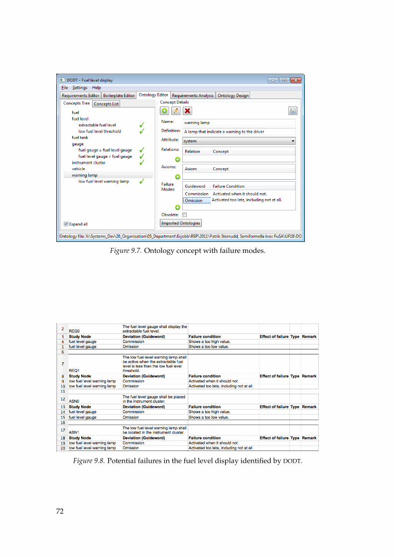
Figure 9.7. Ontology concept with failure modes.
Figure 9.8. Potential failures in the fuel level display identified by DODT.
72
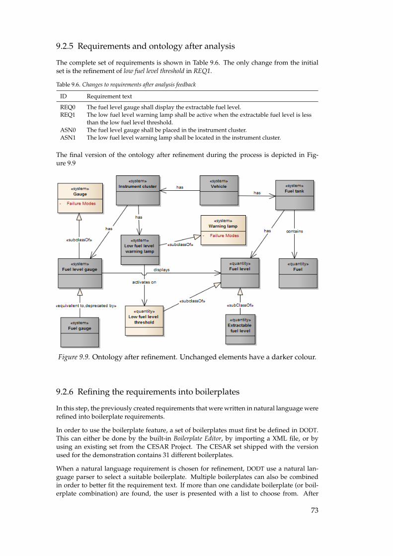
9.2.5 Requirements and ontology after analysis
The complete set of requirements is shown in Table 9.6. The only change from the initialset is the refinement of low fuel level threshold in REQ1.
Table 9.6. Changes to requirements after analysis feedback
ID Requirement text
REQ0 The fuel level gauge shall display the extractable fuel level.REQ1 The low fuel level warning lamp shall be active when the extractable fuel level is less
than the low fuel level threshold.ASN0 The fuel level gauge shall be placed in the instrument cluster.ASN1 The low fuel level warning lamp shall be located in the instrument cluster.
The final version of the ontology after refinement during the process is depicted in Fig-ure 9.9
Figure 9.9. Ontology after refinement. Unchanged elements have a darker colour.
9.2.6 Refining the requirements into boilerplates
In this step, the previously created requirements that were written in natural language wererefined into boilerplate requirements.
In order to use the boilerplate feature, a set of boilerplates must first be defined in DODT.This can either be done by the built-in Boilerplate Editor, by importing a XML file, or byusing an existing set from the CESAR Project. The CESAR set shipped with the versionused for the demonstration contains 31 different boilerplates.
When a natural language requirement is chosen for refinement, DODT use a natural lan-guage parser to select a suitable boilerplate. Multiple boilerplates can also be combinedin order to better fit the requirement text. If more than one candidate boilerplate (or boil-erplate combination) are found, the user is presented with a list to choose from. After
73
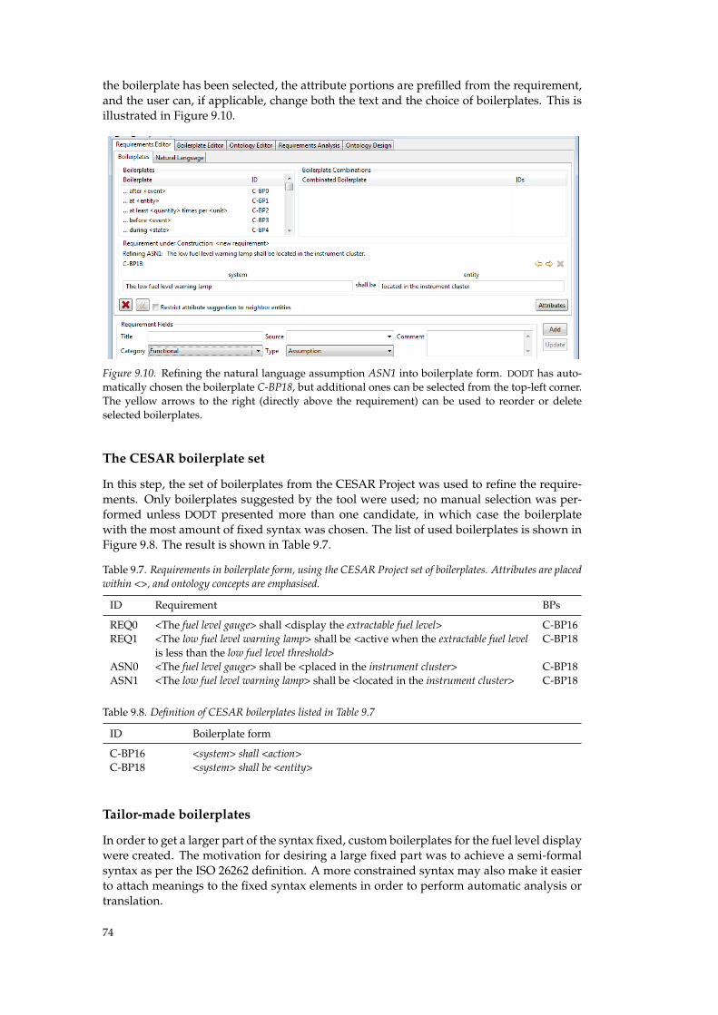
the boilerplate has been selected, the attribute portions are prefilled from the requirement,and the user can, if applicable, change both the text and the choice of boilerplates. This isillustrated in Figure 9.10.
Figure 9.10. Refining the natural language assumption ASN1 into boilerplate form. DODT has auto-matically chosen the boilerplate C-BP18, but additional ones can be selected from the top-left corner.The yellow arrows to the right (directly above the requirement) can be used to reorder or deleteselected boilerplates.
The CESAR boilerplate set
In this step, the set of boilerplates from the CESAR Project was used to refine the require-ments. Only boilerplates suggested by the tool were used; no manual selection was per-formed unless DODT presented more than one candidate, in which case the boilerplatewith the most amount of fixed syntax was chosen. The list of used boilerplates is shown inFigure 9.8. The result is shown in Table 9.7.
Table 9.7. Requirements in boilerplate form, using the CESAR Project set of boilerplates. Attributes are placedwithin <>, and ontology concepts are emphasised.
ID Requirement BPs
REQ0 <The fuel level gauge> shall <display the extractable fuel level> C-BP16REQ1 <The low fuel level warning lamp> shall be <active when the extractable fuel level
is less than the low fuel level threshold>C-BP18
ASN0 <The fuel level gauge> shall be <placed in the instrument cluster> C-BP18ASN1 <The low fuel level warning lamp> shall be <located in the instrument cluster> C-BP18
Table 9.8. Definition of CESAR boilerplates listed in Table 9.7
ID Boilerplate form
C-BP16 <system> shall <action>C-BP18 <system> shall be <entity>
Tailor-made boilerplates
In order to get a larger part of the syntax fixed, custom boilerplates for the fuel level displaywere created. The motivation for desiring a large fixed part was to achieve a semi-formalsyntax as per the ISO 26262 definition. A more constrained syntax may also make it easierto attach meanings to the fixed syntax elements in order to perform automatic analysis ortranslation.
74
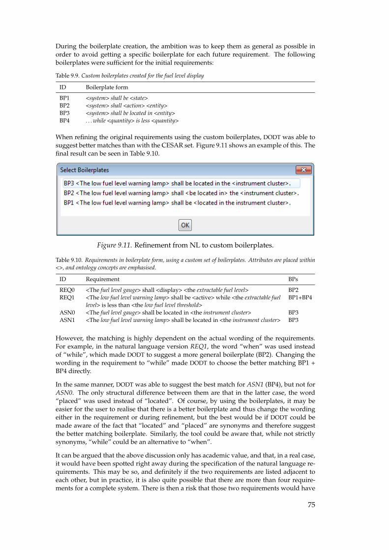
During the boilerplate creation, the ambition was to keep them as general as possible inorder to avoid getting a specific boilerplate for each future requirement. The followingboilerplates were sufficient for the initial requirements:
Table 9.9. Custom boilerplates created for the fuel level display
ID Boilerplate form
BP1 <system> shall be <state>BP2 <system> shall <action> <entity>BP3 <system> shall be located in <entity>BP4 . . . while <quantity> is less <quantity>
When refining the original requirements using the custom boilerplates, DODT was able tosuggest better matches than with the CESAR set. Figure 9.11 shows an example of this. Thefinal result can be seen in Table 9.10.
Figure 9.11. Refinement from NL to custom boilerplates.
Table 9.10. Requirements in boilerplate form, using a custom set of boilerplates. Attributes are placed within<>, and ontology concepts are emphasised.
ID Requirement BPs
REQ0 <The fuel level gauge> shall <display> <the extractable fuel level> BP2REQ1 <The low fuel level warning lamp> shall be <active> while <the extractable fuel
level> is less than <the low fuel level threshold>BP1+BP4
ASN0 <The fuel level gauge> shall be located in <the instrument cluster> BP3ASN1 <The low fuel level warning lamp> shall be located in <the instrument cluster> BP3
However, the matching is highly dependent on the actual wording of the requirements.For example, in the natural language version REQ1, the word “when” was used insteadof “while”, which made DODT to suggest a more general boilerplate (BP2). Changing thewording in the requirement to “while” made DODT to choose the better matching BP1 +BP4 directly.
In the same manner, DODT was able to suggest the best match for ASN1 (BP4), but not forASN0. The only structural difference between them are that in the latter case, the word“placed” was used instead of “located”. Of course, by using the boilerplates, it may beeasier for the user to realise that there is a better boilerplate and thus change the wordingeither in the requirement or during refinement, but the best would be if DODT could bemade aware of the fact that “located” and “placed” are synonyms and therefore suggestthe better matching boilerplate. Similarly, the tool could be aware that, while not strictlysynonyms, “while” could be an alternative to “when”.
It can be argued that the above discussion only has academic value, and that, in a real case,it would have been spotted right away during the specification of the natural language re-quirements. This may be so, and definitely if the two requirements are listed adjacent toeach other, but in practice, it is also quite possible that there are more than four require-ments for a complete system. There is then a risk that those two requirements would have
75
several other requirements in between. If the different wording would not be found andcorrected, it could lead to confusion by readers who might wonder if they are different fora reason. By using the same fixed syntax in the boilerplate, this is avoided.
Another solution is to change the ontology relations between the concepts “instrumentcluster”, “gauge” and “warning lamp”. For example, instead of the relation “has” whichwas derived from the initial information model, a more specific relation “located in” couldbe used. Although this does not affect the boilerplate selection, guidance is provided at thetime of writing the requirement. However, the requirements analysis does not flag that theword “placed” is used instead of “located”. Neither the analysis or the boilerplate selectionseems to factor in the name of the relations, only the fact that there is a relation seems tomatter. There are also no way to specify a synonym to a relation in DODT. This could be afuture improvement of the tool.
The previous paragraph also begets the question on how similar the ontology and the re-quirements should be. This question is discussed in more detail in the next section.
9.3 Evaluation
In this section, an evaluation of the above case study is presented. It will focus more onthe concepts of domain ontologies and boilerplates rather than the tool DODT itself. It ishowever worth to mention that DODT as a tool is quite user-friendly and easy to work with.For example, it is easy to reach relevant features without using the main menu. The user-friendliness of any requirements tool is likely to be a key success factor for its acceptanceamong the user base.
There is also a potential psychological factor relating to the requirements analysis feature.As the feedback from the tool is available directly, users may use it to challenge themselvesto write good requirements, which of course would affect the quality in a positive way.
One feature that is under development in DODT and therefore could not be tested is theautomatic generation of an ontology by using a document as input. This feature can poten-tially simplify the ontology creation, but is likely to require some experience with ontolo-gies in order add or remove concepts or relations after the generation process.
It should be noted that the case study only was done on a very small number of require-ments, so it is impossible to draw any conclusions on the scalability or behaviour of a largersystem, or even the same system at a more technical level with more requirements.
9.3.1 Ontology quality
The success of the tool and indeed the technique itself is highly dependent on the quality ofthe ontology. If important concepts are missing, the guidance and analysis will suffer. If therelations or axioms between the concepts are suboptimal, the user is likely to be distractedby suggestions that do not make sense. Additionally, if the ontology also is used for thepurpose of conveying a common vocabulary, it becomes even more important to ensure thequality of the contents. Therefore, any shared ontology should be centrally managed andnew entries carefully reviewed before being entered into the ontology.
On the other hand, it seems likely that new concepts and relations will be identified duringthe requirements specification. To avoid delays during the specification, it should be easyfor the users to add missing entries. However, if the users are not familiar with the ontology
76
technique, they might include entries that are not optimal, which would degrade the qual-ity. Therefore, a balance between ease of use and quality control is needed for ontologiesthat is used by more than one person.
9.3.2 Ontology versus requirements
One observation from the case study is that the closer the names of the relations in the on-tology are to the real world, the better is the guidance provided by DODT during require-ments formulation. Also, if there are no relations between two concepts that are used in thesame requirement, this will be identified as opacity when using the requirements analysisfeature. The only way to make the opacity warnings disappear is to add a relation betweenthe concepts, either directly or indirectly (e.g., to a higher-level concept). Additionally, ifthe requirements do not make use of the concepts in the ontology, the requirements analysisfeature will lose its usefulness as every identified concept will be flagged as noise.
However, if the ontology technique works best when both its concepts and relations matchesthe requirements, then what is the difference between the requirements and the ontology?Cannot the ontology replace the requirements altogether?
First, it should be pointed out that in this thesis, the purpose using the technique is tofacilitate the production of natural language-like requirements with low ambiguity. In fact,the creation of the ontology could be seen as nothing more than an intermediary step in theprocess of writing the requirements, much as an information model can be used to createan abstraction of the reality. Indeed, if the ontology only is used by a single person andnot shared within the organisation, this would be quite close to the truth. However, thetechnique will be even more powerful if a shared ontology is used, because it would leadto a common vocabulary and also the possibility to find conflicts between requirements indifferent systems.
Secondly, if the ontology contains concepts and relations that are shared through the or-ganisation (e.g., derived form the Driver’s Manual), the contents should not be more spe-cific than what all stakeholders can agree is useful. The actual requirements can howeverbe more specific without affecting the ontological elements. For example, during the moretechnical design phase of the fuel level display, REQ1 could be refined into:
The low fuel level warning lamp shall be activated when the extractable fuel level has been less than 10%of the total tank volume for a time period exceeding 30 seconds.
While concepts such as “total tank volume” and possibly also “time period” and “seconds”might need to be included in the ontology if they not already exist, there is no point inadding the actual values (10% and 30 seconds).
It may also be interesting to compare the ontology with a formal specification (see Chap-ter 7). For formal specifications, it is recommended that natural language versions accom-panies the formal requirements, but that the formal version has precedence. In the case ofontologies, it is the other way around. The ontology, together with the tool DODT, is usedto produce the actual natural language requirements. The resulting requirements can thenbe placed under change management and validated by the stakeholders.
In some sense, the ontology can be seen as a modelling tool for high-level requirements inthe problem domain. This may be a suitable viewpoint, because it would make the mostout of the technique in terms of guidance during specification and requirements analysis.It would of course have to be made explicit within the organisation that the ontology is amodel and that the actual requirements used for system development are stored elsewhere.
77
By using the above reasoning, the previously posed question regarding the relationshipbetween the concepts instrument cluster and fuel level gauge can be answered. It should bethe more specific “located in” rather than the original “has”, which was taken directly fromthe information model. It should be pointed out that the “has” relationship appears tobe quite common in information models; this would be something to keep in mind whenderiving ontology relations from that type of sources.
Finally, there is another aspect that must be discussed. If a natural language requirement isthe output from the process, what about the concept description available in the ontology?Should that information be part of the requirement or not? This question can be further ex-tended: Which information should be specified in the requirements, which information should existin the ontology, and finally, what should not specified at all because it is “common knowledge”?.This question is equally relevant when there is no ontology but instead only a glossary.
From an ambiguity point of view, the term “common knowledge” above should raise awarning flag, because that is just the kind of assumption that comes back to haunt projectslater on. On the other hand, the line must be drawn somewhere; at some point the value ofwriting detailed definitions disappears. The question is where that point is. For example,is it necessary to define what the word “colour” actually means?
To decide whether to place information in the requirements or in the ontology is perhapseven harder. A requirement that is short and concise is easier to understand, but if that isachieved by omitting certain information such as implicit assumptions, there is a high riskof ambiguity. Compare the following three versions of the same requirement:
a) “The fuel level gauge shall display the extractable fuel level to the driver.”
b) “The fuel level gauge shall display the extractable fuel level.”
c) “The fuel level gauge shall display the fuel level.”
Alternatives b) and c) do not state to whom or what the fuel level is supposed to be dis-played to, while alternative a) makes it explicit. Can it be assumed that it is always thedriver? Not necessarily - it depends on the interpretation of the word “display”. Since it isdangerous to make assumptions regarding interpretations, it would then be a good idea tohave a clear definition of the word “display” in the ontology or glossary.
Alternative c) furthermore omits the word “extractable”. Possibly, it could be clarified ina glossary or an ontology that “fuel level” actually means “extractable fuel level”, but thismay not be an option if other types of fuel level must be referred to, e.g., “measured fuellevel”. In some occasions, the actual fuel level may be of interest as well, e.g., due to fireconcerns.
Although a requirement statement can be made more concise by moving definitions to aglossary, it places greater demand on the reader to actually refer to the glossary. Addition-ally, it should somehow be made obvious that a certain word have an external description.There is also a risk that a reader will refrain from referring to the glossary because theythinks that the meaning is obvious, thus leading to misunderstandings. This can be some-what mitigated with tools like DODT as the concept description is displayed when the re-quirement is written. In any case, it would be good practice to discuss the requirements for-mulations together with the glossary definitions during the requirements validation step.
More problematic is the fact that what actually happens when clarifying words are ex-tracted and placed in a glossary or an ontology is that the requirement itself is extendedto an external source. This means that the need for change management is extended tothat source, as it must be possible to relate a particular version of a requirement with theparticular description that was current at the time of specification.
78
However, a simpler solution may be to extract the description and store it together with theaccepted requirement. On the other hand, if this is done, another question arise: should thestored version be used when the requirement is modified, or should the current descriptionfrom the ontology be retrieved?
Unfortunately, even with adequate change management in place, it can be dangerous ifthere exist multiple versions of a description, because the users of the requirements wouldhave to keep different interpretations of the same concept in their minds at the same time.
One way to avoid or at least reduce the problem is to have a strict quality control whichensures that only descriptions and entries that there already are commonly established inthe organisation are included, and that only minor changes that do not change the actualmeaning are performed afterwards. This is of course easier said than done.
9.3.3 Boilerplates
If requirements are to be written in boilerplate form, it is important to have a set of boiler-plates with as few elements as possible while still allowing the engineer to express domainspecific requirements in it. If the set is too large, there is a risk of too disparate formula-tions. If it is too small, the quality of the requirements may be affected because importantinformation is left out because it does not fit into the templates.
It will therefore be necessary to spend some time developing a suitable set of boilerplates.It is also possible that different sets will be needed for different departments. The userswho would ultimately use such a tool are likely to need some training before starting usingit. This sentiment is also shared by Farfeleder et al. :
The selection of suitable boilerplates for a requirement is not always trivial and requires a bitof experience with the boilerplates method. [20]
However, this is not unique to DODT; the same thing would apply to any other tool,whether it is for requirements, modelling or a new programming language.
9.3.4 Hazard identification
Although no general conclusions can be drawn from such a small case study, the resultsseem promising, since the hazards identified by DODT were approximately the same as inthe requirements document for the existing fuel level display system. As was stated previ-ously, the hazards related to the concepts in the requirements were derived from the moregeneral concepts in the ontology (e,g, the hazards identified for the fuel level gauge actuallycame from the gauge concept).
If the above results hold for larger systems as well, the tool may be able to both reducemanual work and to ensure that likely sources of hazards are not forgotten. However,there is no guarantee that all hazards will be detected, so an experienced engineer shouldalways review the result manually, and if necessary add missing hazards.
In the case study, the failure modes were associated with the components themselves. Inan ISO 26262 setting, this kind of hazard analysis would correspond to activities done at,or below, the Functional Safety Requirements level.
79

Part V:
Discussion

10. Discussion
In the introduction, the following question was posed: is it possible to achieve unambiguousrequirements in a context of functional safety and ISO 26262?
The short answer, based on the findings in earlier chapters is that “it depends”.
There is no evidence that unambiguous requirements are unachievable, although it cer-tainly is no trivial task to get it done for a complex in-vehicle E/E (Electrical/Electronic)system. However, as has been stated and demonstrated in earlier chapters, requirementsspecified in natural language are inherently ambiguous. At the same time, ISO 26262 statea strong preference that requirements should be written in natural language.
If the interpretation is made that the preference towards natural language indeed is a de-mand, then the answer must be no. On the other hand, ISO 26262 is rather ambiguous inboth its own definitions and its requirements. This gives some leeway for interpretations.
For example, if, as was suggested in Chapter 7, the rationale is that all stakeholders shouldbe able to read the requirements without requiring training in formal methods, then itshould also be acceptable to
a) use a CNL (Constrained, or Controlled, Natural Language) together with an ontol-ogy in order to ensure that only well-defined concepts that relate to each other areused, or
b) use a formal notation and then translate the formally specified requirements into acorresponding natural language representation. To preserve the unambiguousness,the formal version should have precedence over any derivations.
If any of the above alternatives could be done, then the answer would change to yes. Toachieve even more quality, the ontology approach could be used when transforming formalrequirements into natural language derivations.
It must of course be stated that there are no methods or techniques that in themselveswill guarantee unambiguous requirements; the results will depend on how the methods ortechniques are executed.
In the sections below, a number of more specific topics are discussed. Most of them connectdirectly to points made in the previous chapters, but a few also discuss findings that havebeen made during the process but were too small to merit a dedicated chapter.
10.1 Ambiguities in ISO 26262
A lot of effort has been put into understanding the requirements in ISO 26262. One reasonfor this is that important concepts are poorly or ambiguously defined. This is slightly ironicsince the ISO 26262 forbids such things for organisations that wish to comply with the stan-dard. It should be noted that this thesis only focused on a very small part of the standard.Other parts may be more completely defined. In any case, some of the more problematicareas are summarised below.
83
◦ There are no definitions of syntax, semantics or natural language.
◦ The definitions of informal notation, semi-formal notation and formal notation arevague and ambiguous.
◦ The definition of SGs (Safety Goal) is ambiguous: is a SG considered a requirement ornot?
◦ There is an implicit assumption that requirements only will exist in one notation.
◦ There are contradictory directives regarding interpretation of tables.
◦ It is unclear whether a formal notation can replace a semi-formal one. According tothe definitions, it should be acceptable, but according to the tables, the opposite mayapply.
ISO 26262 also seems to have an ambivalent and inconsistent approach towards formalmethods. Although natural language is preferred, and semi-formal methods always ishighly recommended where formal methods are merely recommended, the standard domention formal methods and formal notations in several places. However, as the standardis being interpreted at Scania, the semi-formal methods must be deployed in any case. Feworganisations are likely to bother doing both, and so will be satisfied with the semi-formalmethod. Nevertheless, why bother writing about formal methods if it always must be doneafter everything else has been done?
For good or bad, the standard also seem to have some prejudices about programming lan-guages. For example, ISO 26262-6 Clause 8 recommends against, or for higher ASILs (Au-tomotive Safety Integrity Level), strongly recommends against the use of recursion. Whilethis certainly makes sense for imperative languages such as C, the consequence is that italso recommends against functional programming languages. Nevertheless, it can be ar-gued that functional languages are at least as suitable, if not more so, for the developmentof safety-critical systems. For example, the functional language ML was developed for thepurpose of mathematically proving properties in programs. Another example is Erlang,which was created for the purpose of developing software in telephone switches. In tele-phone switches, reliability is of paramount concern, and this has influenced the language.It should be noted that reliability is not the same as safety, but they are related to eachother. It is hard to build a safe system without considering reliability. Additionally, Erlanghas recently been applied outside the telecom industry, for example in situations whereavailability or low transaction times are important.
Although this thesis may appear to be critical against ISO 26262, it must be pointed outthat an organisation that would follow the standard in order to produce safer systems arelikely to do so. However, as with every standard, it is probably possible to get certified,and still not follow the intentions of the standard. The differences will all lie in whetherthe standard is used as a tool to achieve functional safety, or merely adhered to on paperto comply with future regulations.
10.2 Uniform management of requirements
ISO 26262 only applies to requirements related to functional safety. However, the majority,if not all, systems will have other requirements on them regarding e.g., performance oravailability. Such requirements may be managed in a different manner, since there areno demands for change control, unambiguousness, or any other of the aspects covered inChapter 6. Of course, other standards may apply which also mandates good requirementsmanagement. In any case, experience shows that ignoring the requirements part in projectsis a good way towards delays and increased costs.
84
In Chapter 6, it was stated that it would be difficult to fulfil the demands stated by ISO26262 by the means of documents alone. An organisation could instead choose to usea RDM (Requirements Definition and Management) system dedicated for the functionalsafety aspects in order to comply with ISO 26262.
On the other hand, if all requirements (i.e., not only safety-related requirements) were tobe placed in a RDM system with support for change management, traceability, and work-flows, it could become possible not only to comply with ISO 26262, but also gain economicbenefits from an automated impact analysis. If it can be shown that a particular part ofa system is not affected during a modification, then there is no need to spend time andother resources on testing it. There are also other reasons for using a single system for allrequirements independent of type. Some of these are listed below in no particular priority:
◦ It is usually more cost effective to use and maintain a single system.
◦ If a single system is used, more effort and resources can be put into its continuousimprovement. It has potential to become a system that supports the engineers intheir daily work, as opposed to a system that must be used purely to comply withthe standard. In the latter case, the system would probably be seen as burden, andcompliance to ISO 26262 would be lip-service rather than a way to build safe systems.
◦ A good RDM system can provide benefits to the development process regardless ofISO 26262. However, much of those advantages are dependent on that all require-ments exist in the same system.
◦ While it is theoretically possible to separate functional safety requirements from thosethat are not safety-related, the distinction may be harder in reality. The engineerswould have to consider, for each requirement, in what system it should be managed.This would likely be frustrating and also prone to mistakes. Additionally, duringa system modification, a requirement might be revised so that it suddenly becomessafety related. In that case, that requirement (and all refinements and dependen-cies) would have to be moved to the requirement management system responsiblefor functional safety. However, in addition to the extra administration, it would mostlikely also break the traceability in the original system.
10.3 Domain ontologies, boilerplates and DODT
Chapter 9 described a case study where DODT (Domain Ontology Design Tool) was usedto demonstrate the potential benefits of using a domain ontology. Automatic refinementof natural language requirements into boilerplates was also demonstrated. It was foundthat both techniques had potential for reducing ambiguity in requirements. In this section,some considerations that was not covered earlier will be discussed.
One challenge that relates to the case study itself is the a priori knowledge about the fuellevel display. As was briefly remarked, the domain knowledge regarding the extractable fuellevel was included in the system definition and also in the ontology and the requirements.On the other hand, the scenario stated that the system would be developed without moreprior information than what was available in the Driver’s Manual. Still, when the personwho writes the requirements is aware of relevant domain knowledge, it can be argued thatit makes sense to use it, if not for no other reason that it might save an extra iteration lateron, because such information is likely to appear sooner or later in any case.
In the last part of Chapter 9, it was noted that the quality of the ontology is important forthe success of the technique. It was also found that concepts in the ontology preferablyshould be quite stable (i.e., not be modified unless strictly necessary). Therefore, much
85
consideration must be given to how an ontology should be managed. Some importantquestions are:
1. Should there be one central, corporate-wide ontology, or multiple smaller ontologies,e.g., for different departments or even systems?
2. Who should be allowed to suggest new entries for inclusion in the ontology?
3. Who should perform the reviewing of new concepts?
4. Should it be allowed to change an existing item? If so, in what circumstances?
5. What should be the primary language in the ontology?
6. Who should be responsible for the ontology?
No clear answers exists to the above questions, because they are primarily of an organisa-tional rather than a technical nature.
However, Scania do have valuable experience with these kind of systems from the ScaniaLexicon and Scania Checker. In the case of the Scania Checker, the database was centrallymanaged, but the interface offered an easy way of submitting new terms for review andinclusion. The Senior Language Advisor at Scania [39], who is in charge of the ScaniaChecker and the subsequent tool Acrolinx IQ, is convinced that a central ontology is thebest approach. The main argument is that the purpose of an ontology or a lexicon is toachieve a common repository of concepts; if multiple ontologies were to be used, e.g., onefor each department, there is a high risk that identical terms with disparate meanings willbe defined.
Even though there are strong arguments for a central system, it may be useful to distributethe administration so that decisions can be taken close to the engineers who would usethe system. In order to succeed, it is important that domain experts and terminologistscooperate closely in order to get a qualitative ontology. How this should be done fastenough to avoid stalling the development is outside this discussion, but Scania appears tohave managed a good workflow in the Scania Checker project, so it should be possible inthis case as well.
Although the discussion about ontologies has so far mostly dealt with the challenges asso-ciated with the technique, the intention is not to discourage its use. The technical part is nomore complicated than other information systems, but as usual, the main challenge is howthe technique is to be used.
If the organisational aspects can be solved, and an ontology-based tool like DODT could beused for all systems, it would mean that all requirements would exist in the same database.While this in itself can be achieved by any decent RDM system, the ontology gives at leasttwo additional advantages:
I. Possibility to extract information about which systems have requirements on aparticular part or subsystem in the vehicle even though it is not explicitly listed.
II. Possibility to automatically find conflicts or inconsistencies globally, i.e., betweendifferent systems. An example is if the systems A and B requires mutually ex-clusive output from the component X. In addition to inconsistencies, the othermetrics described in Chapter 8 are of course also valuable in order to increase thequality of the requirements.
Even more interesting, if the capabilities of DODT could be integrated in a full-fledgedRDM system, in turn supporting or integrating the tools used by the technical writers, thefollowing benefits can be gained (as opposed to using a traditional RDM system):
I. less ambiguous requirements,
86
II. improved understanding between different departments, and
III. increased possibility for future automated translation.
Finally, it could also give engineers and managers real-time information about the currentstatus for each system.
10.4 Notations - which one is best?
In this thesis, different types of notations have been covered. Another major considerationhas been the applicability of formal methods. Although no evaluation has been done wherethe different techniques have been independently compared to each other in the context ofa real system, some thought have been given to the fitness of each notation and technique.The question that may very well be asked, then, is “which notation is the best one in generaland for Scania?”
Unfortunately, there is no clear answer to that. If it was, it can be surmised that mostbusinesses already would be using that technique.
One thing that usually is held against formal notations is that they require training beforethey can be used. This is of course not denied by the proponents of such notations ormethods, and it is also one of the reasons that this thesis was unable to perform the origi-nally planned evaluation of three different formal notations – it was simply to complicatedwithout prior experience.
Additionally, there are several formal methods available, and where one method might bea close fit for a particular project, it may be unsuitable for the next one. All methods havetheir strengths and weaknesses. As if that was not enough, it may be not a good idea to useformal methods throughout an entire project, but rather in smaller parts where e.g., safetyis of paramount concern.
On the other hand, there appears to be some prejudice against mathematical methods andsymbols in the context of programming, which probably affects the uptake of formal meth-ods. This is a bit strange since programming and computer science to a large extent areapplied mathematics. To quote Hall: “People have a fear of new symbols, but mathemati-cal symbols are introduced to make mathematics easier, not more difficult” [25]. Abrial, ofthe B language fame, goes one step further:
We also hear very frequently that we must hide the use of mathematical notation becauseengineers will not understand it and be afraid of it. This is nonsense. Can we imagine thatit is necessary to hide the mathematical notation used in the design of an electrical networkbecause electrical engineers will be frightened by it? [1]
Be that as it may; what seems to be clear is that formal methods do have a lot of benefits,but that they also require both commitment and training to succeed. What, then, about theother end of the scale, namely informal notations?
In the previous statement that training is necessary before formal notations can be used forwriting requirements, it seems to exist an unstated assumption that this is not required fornatural language. However, as was shown in previous chapters, natural language is highlyambiguous. It can be discussed whether it is even theoretically possible to write a set ofunambiguous requirements in natural language.
On the other hand, surely it must be possible to write good enough requirements in naturallanguage? This is not an unrealistic assumption, but it can definitely be discussed, since
87
there is a lack of literature showing successful examples. Furthermore, even assuming thatit indeed can be done, another question arise: will it take less time to attain the experienceand skills of writing good enough natural language requirements as opposed to attend acourse in formal methods? For example, Leeb-Lundberg [38] found that it takes more thanthree semesters for students of law to learn how to use a specific juridical term correctly. Inthis case, “correctly” means it is used in the same way that experienced law professionalsdo. The comparison is relevant because juridical language attach domain-specific meaningto certain words in the same way that is done in the field of engineering. The results sug-gest that it may take considerable effort to become proficient in writing natural languagerequirements correctly.
Unfortunately, it appears that requirements written natural language without any support-ing tools are doomed to remain highly ambiguous. In the future, with the support of morecapable proof techinques, formal methods are likely to be increasingly deployed. Organi-sations that embrace such methods and notations are likely to gain a competitive edge be-cause their products will have less defects, and also because formal methods do not workwell with the ad hoc programming that is commonly in use today. More structured ap-proaches to software development means less redesign and less bug fixing, which furtherdecrease development costs and, even more importantly, decreases the ever more impor-tant time to market.
In the meantime, it appears to be worthwhile to consider semi-formal approaches, andespecially techniques that use CNLs. Such techniques will probably prove to be usefulregardless of the adoption of formal methods, because they can reduce the ambiguity whencommunicating with customers and other stakeholders.
88
Part VI:
Conclusions and future work

11. Conclusions
This chapter contains the key points of the previous chapters. Before going into the conclu-sions in depth, an introduction by way of looking into the past is provided.
More than 35 years ago, Frederick P. Brooks wrote his renowned book The mythical manmonth. Eleven years later he wrote the paper No silver bullet where he postulated that mostof the easy problems in computer science had been solved, and what remained was theintrinsic problem that writing good software is hard. Both the No silver bullet paper andthe original book as well as some additional chapters are available in the 20th anniversaryedition of The mythical man month [11]. There, it can be read (emphasis original):
I believe the hard part of building software to be the specification, design, and testing of this conceptualconstruct, not the labour of representing it and testing the fidelity of the representation. [. . . ] If this istrue, building software will always be hard. There is inherently no silver bullet.
What Brooks stated in 1986 seems to be true in 2011 as well. Tools, languages and tech-niques will never be enough: the major challenges lies in the process. However, the processcan be made much more efficient with the correct tools.
11.1 Requirements in general
The conclusions in this section cover different aspects of requirements definition and man-agement. Requirements is an important part of ISO 26262, and it will be virtually impossi-ble to fulfil the directives in ISO 26262 without a lot of considerations on how requirementswill be specified and managed throughout the system life-cycle.
I. Writing good requirements are much harder than it appears, regardless of formor notation.
II. Formal methods can reduce ambiguity and increase confidence about the safetyof a system.
III. Formal methods do take some effort to understand, and even more effort to be-come proficient in. However, it is not certain whether it takes longer to learnformal methods than to become so experienced in writing natural language re-quirements that most ambiguities can be avoided.
IV. Top-level requirements should not be treated in isolation; it is important to createtraceability throughout the development process.
V. A good RDM (Requirements Definition and Management) system is necessary toachieve recommended and, by ISO 26262 mandated specification and manage-ment of requirements.
VI. According to literature and research (see Chapter 6), a lot of money is wasted dueto lack of good requirements. Bad requirements are also likely to lead to waste,which goes against the first Lean principle (“Eliminate waste”) as described byMary and Tom Poppendieck [44].
91
11.2 Requirements, ambiguity and ISO 26262
The following four conclusions together answer the main question formulation of the the-sis (is it possible to achieve unambiguous requirements in a context of functional safety and ISO26262?):
I. Writing unambiguous requirements in natural language is unfeasible, if not out-right impossible.
II. ISO 26262 has a strong bias towards natural language for requirements specifica-tions, while at the same time demanding unambiguous requirements.
III. Assuming that I and II are true, then it is not possible to comply with ISO 26262.
IV. However, if the bias in ISO 26262 towards natural language is interpreted to meanthat there shall exist a version of a requirement that can be interpreted as a naturallanguage statement, then it becomes possible to comply with the ISO 26262.
Furthermore, two additional conclusions regarding ISO 26262 are worth pointing out:
I. ISO 26262 is not written in adherence to its own directives. The standard demandsthat requirements must be unambiguous and comprehensible, but in the standarditself, many requirements are using concepts that are ambiguous or not definedat all.
II. ISO 26262 is written in a way that makes formal methods the “second choice”after semi-formal methods (which is an undefined concept itself). This is likelyto make organisations avoid using formal methods even though both researchand practical experience demonstrates a particular suitability for such methodsin safety-critical systems.
11.3 Ontologies and constrained natural language
Domain ontologies can be thought of as a (domain specific) database of concepts and rela-tions between them. The following conclusions are derived primarily from the case studyin Chapter 9 and from conservations with the Senior Language Advisor at Scania. In thecase study, a research tool named DODT (Domain Ontology Design Tool) was used to writerequirements with the support of an ontology. Furthermore, a CNL (Constrained, or Con-trolled, Natural Language) in the form of boilerplates was used to refine the natural lan-guage requirements.
I. A key factor for reducing ambiguousness is to use a shared vocabulary betweenall stakeholders. A domain ontology is one way to achieve this. The ambiguitycan be further reduced by imposing restrictions on the syntax, e.g., by using aCNL.
II. One advantage of domain ontologies is that metrics on the requirements qualitycan be established (see Chapter 8). This makes it easier to detect problems in therequirements.
III. By integrating domain ontologies and CNLs in the requirements specification pro-cess, e.g., by a tool such as DODT, the quality of the requirements can be furtherincreased. In order to manage the traceability requirements in ISO 26262, it maybe necessary to integrate the capabilities of DODT in a larger system.
IV. Change management of the ontology itself will be necessary if the requirementswill be depending on the concept definitions in the ontology. It may also be nec-
92
essary to manage the dependencies between the requirements and the ontologyconcepts, but this depends on the implementation.
V. The major challenge in applying an ontology is to make it easy enough to up-date but without losing quality. For shared ontologies, central administration isnecessary, but this is mainly an organisational question rather than a technicalone. However, Scania has previous experience with managing such processes, soit seems plausible that a good balance can be achieved.
93
12. Future work
Below are a some suggestions for how the results of this thesis can be extended, as wellas other identified issues that might merit further research. These are divided into twocategories: those that are applicable mainly for Scania and those of a more general nature.
12.1 Scania specific
Evaluate different formal notations and methods
Both research and practical experience shows that formal methods can provide multiplebenefits during specification and development. It would be interesting to apply differentmethods to the same system that was used in this thesis (the fuel level display) and evaluatethe fitness from a Scania perspective.
Evaluate RDM (Requirements Definition and Management) systems
A key finding is that documents are unsufficient for requirements storage and managementif traceability and change management is desired. However, such systems will have a pro-found effect on the organisation. Therefore, a throughout investigation of the actual needsshould be done before any solution is purchased or developed. Indeed, it may be the casethat in order to cope with ISO 26262, a larger system which can support the entire systemlife-cycle may be necessary.
Evaluate DODT on a larger scale
While the case study in Chapter 9 showed great promise, it would be interesting to try itin a larger scale. As a first step, all requirements for the fuel level display system shouldbe added, but preferably also requirements from other systems. This could give additionalinsights in both the number of required boilerplates as well as potential problems with theontology technique. Additionally, integration with RDM systems could be investigated.
Investigate potential synergy effects by using an ontology more extensively
Since both the After Market and the Research and Development departments have similarchallenges in regard to the lack of consistent vocabulary, and also because it would beefficient if both departments used the same vocabulary, it could be investigated how thiscan be achieved.
Investigate the possibility to automatically generate natural language versions from aformal notation
It was postulated that since formal notations have both complete syntax and semantics, itshould be feasible to automatically generate a natural language version from the formalone. This postulate merits further research, and could be especially fruitful since Scaniahas considerable experience in the field of language management.
94
12.2 General
Cooperate with ISO in order to improve ISO 26262
If some of the ambiguity and vagueness in ISO 26262 could be removed, the interpretationof the standard would be more predictable. Additionally, it may be that some parts of thestandard are interpreted in a way that the authors of the standard did not intend, which ofcourse would be unfortunate.
Evaluate SBVR and OCL
In Chapter 4 (“Related work”), SBVR (Semantics of Business Vocabulary and Business Rules)and OCL (Object Constraint Language) were described as something similar to domain on-tologies and boilerplates. Although the latter concept was chosen due to the tool DODT(Domain Ontology Design Tool) and also due to the connection with the CESAR Project,both SBVR and OCL merits a further investigation, especially since it seems to be possibleto automatically generate source code from OCL.
Combine SBVR with domain ontologies
In the tool DODT, domain ontologies are combined with boilerplates. It would be veryinteresting to see what could be done if a domain ontology instead was combined withSBVR and potentially also OCL.
95
Bibliography
List of all references
[1] Abrial, Jean-Raymond. Modeling in Event-B: System and Software Engineering. Cambridge Uni-versity Press, 2010. ISBN: 9780521895569.
[2] Alagar, V.S. and Periyasamy, K. Specification of Software Systems. 2nd ed. Texts in ComputerScience. Springer, 2011. ISBN: 9780857292766.
[3] Alexander, Ian F. and Stevens, Richard. Writing Better Requirements. Addison-Wesley, 2002.ISBN: 0321131630.
[4] AlloyCommunity. Alloy Community. Project website. Aug. 2011. URL: http://alloy.mit.edu/community/.
[5] Almqvist, Ingrid and Sågvall Hein, Anna. “A Language Checker of Controlled Language andits Integration in a Documentation and Translation Workflow”. In: Translating and the Computer22: Proceedings of the Twenty-second International Conference on Translating and the Computer 16-17November 2000, London. London, Nov. 2000.
[6] Almqvist, Ingrid and Sågvall Hein, Anna. “Defining ScaniaSwedish - A Controlled Languagefor Truck Maintenance”. In: Proceedings of The First International Workshop On Controlled Lan-guage Applications. Leuven, Belgium, Mar. 1996.
[7] Bajwa, I.S., Bordbar, B., and Lee, M.G. “OCL Constraints Generation from Natural LanguageSpecification”. In: Enterprise Distributed Object Computing Conference (EDOC), 2010 14th IEEEInternational. Oct. 2010, pp. 204–213.
[8] Bowen, J. P and Hinchey, M. G. “Seven more myths of formal methods”. In: IEEE Software 12.4(July 1995), pp. 34–41. ISSN: 0740-7459.
[9] Bowen, J. P and Hinchey, M. G. “Ten commandments of formal methods”. In: Computer 28.4(Apr. 1995), pp. 56–63. ISSN: 0018-9162.
[10] Bowen, J. P and Hinchey, M. G. “Ten commandments of formal methods... ten years later”. In:Computer 39.1 (Jan. 2006), pp. 40–48. ISSN: 0018-9162.
[11] Brooks, Frederick P. The Mythical Man-Month: Essays on Software Engineering, Anniversary Edi-tion. 2nd ed. Addison-Wesley, 1995. ISBN: 0201835959.
[12] CESAR Project. Definition and exemplification of RSL and RMM: D_SP2_R2.2_M2. CESAR Projectdeliverable D_SP2_R2.2_M2. Oct. 2010. URL: http://www.cesarproject.eu/fileadmin/user_upload/CESAR_D_SP2_R2.2_M2_v1.000.pdf.
[13] CESAR Project. Survey Report on Modeling Languages, Components Technologies and ValidationTechnologies for Real-Time Safety Critical Systems – v 2.0: D_SP3_R1.2_M1. CESAR Project deliv-erable D_SP3_R1.2_M2. Apr. 2010. URL: http://www.cesarproject.eu/fileadmin/user_upload/CESAR_D_SP3_R1.2_M2_v1.000.pdf.
[14] CESAR Project. The CESAR Project. Project website. Nov. 2011. URL: http://www.cesarproject.eu/.
[15] Chomsky, Noam. Syntactic Structures. Janua linguarum. Series minor, 4. Seventh printing, 1968.The Hague: Mouton, 1957.
[16] CMMI Product Team. CMMI for Development, Version 1.3. Technical Report. CMU/SEI-2010-TR-033. Nov. 2010. URL: http://www.sei.cmu.edu/reports/10tr033.pdf.
[17] Cooke, John. Constructing Correct Software. 2nd ed. London: Springer, 2005. ISBN: 1852238202.
[18] DODT. DODT User Manual version 1.2.4. Manual bundled with the application. Apr. 2011.
96
[19] Erlandsson, Caroline. Requirements improvement in Functional Safety. Master thesis – Scania in-ternal version. Final title and date are preliminary. Department of Information Technology,Uppsala University, Jan. 2012.
[20] Farfeleder, Stefan et al. “Ontology-Driven Guidance for Requirements Elicitation”. In: Proceed-ings of the 8th extended semantic web conference on The semanic web: research and applications - Vol-ume Part II. ESWC’11. Location: Heraklion, Crete, Greece. Berlin, Heidelberg: Springer-Verlag,2011, pp. 212–226. ISBN: 9783642210631.
[21] Frappier, Marc and Habrias, Henri. Software Specification Methods. London: Springer, 2001.ISBN: 1852333537.
[22] Glass, Robert L. Software Runaways: Lessons Learned from Massive Software Project Failures. Pren-tice Hall, 2007. ISBN: 013673443X.
[23] Gove, Philip Babcock. Webster’s third new international dictionary of the English language unabridged.Könemann, 1993. ISBN: 3829052928.
[24] Gruber, Thomas R. “Toward principles for the design of ontologies used for knowledge shar-ing”. In: International Journal of Human-Computer Studies 43 (1993), pp. 907–928.
[25] Hall, A. “Seven myths of formal methods”. In: IEEE Software 7.5 (Sept. 1990), pp. 11–19. ISSN:0740-7459.
[26] Harrison, John. Handbook of Practical Logic and Automated Reasoning. Cambridge: CambridgeUniversity Press, 2009. ISBN: 9780521899574.
[27] Hull, Elisabeth, Jackson, Ken, and Dick, Jeremy. Requirements Engineering. 3rd ed. London:Springer, 2010. ISBN: 9781849964043.
[28] IEEE. IEEE Recommended Practice for Software Requirements Specifications. IEEE RecommendedPractice. 1998.
[29] INCOSE. A Consensus of the INCOSE Fellows. Organisation website. Dec. 2011. URL: http://www.incose.org/practice/fellowsconsensus.aspx.
[30] INCOSE. Brief History of Systems Engineering. Organisation website. Dec. 2011. URL: http://www.incose.org/mediarelations/briefhistory.aspx.
[31] International Organization for Standardization. International Standard 26262: Road vehicles –Functional safety. International Standard. First edition. Nov. 2011.
[32] Jackson, Michael. Software Specifications and Requirements: a lexicon of practice, principles and prej-udices. Addison-Wesley, 1995. ISBN: 0201877120.
[33] Jazequel, J. -M and Meyer, B. “Design by contract: the lessons of Ariane”. In: Computer 30.1(Jan. 1997), pp. 129–130. ISSN: 00189162.
[34] Johannessen, Per, Törner, Fredrik, and Torin, Jan. “Actuator Based Hazard Analysis for SafetyCritical Systems”. In: Computer Safety, Reliability, and Security. Ed. by Heisel, Maritta, Ligges-meyer, Peter, and Wittmann, Stefan. Vol. 3219. Lecture Notes in Computer Science. SpringerBerlin / Heidelberg, 2004, pp. 130–141. ISBN: 978354023176-9.
[35] Johansson, Jessica and Karlsson, Natalie. Gap analysis of Scania development of electric functional-ity and ISO 26262. Master thesis – Scania internal version. Mälardalen University College, June2011.
[36] Kaiya, H. and Saeki, M. “Ontology based requirements analysis: lightweight semantic process-ing approach”. In: Quality Software, 2005. (QSIC 2005). Fifth International Conference on. Sept.2005, pp. 223–230.
[37] Kaiya, H. and Saeki, M. “Using Domain Ontology as Domain Knowledge for RequirementsElicitation”. In: Requirements Engineering, 14th IEEE International Conference. IEEE, Sept. 2006,pp. 189–198. ISBN: 9780769525556.
[38] Leeb-Lundberg, Emma. Att lära sig yrka - Om studenters idiomatiska utveckling i samband med tvåfackord. Thesis. Department of Scandinavian Languages, Stockholm University, Feb. 2007.
[39] Leeb-Lundberg, Emma. Discussion in person and by email with the Senior Language Adviser atScania. 2011.
[40] Leveson, Nancy. Safeware: System Safety and Computers. Addison-Wesley, 1995. ISBN: 0201119722.
97
[41] Miller, George A. “WordNet: a lexical database for English”. In: Communications of the ACM 38(Nov. 1995), pp. 39–41. ISSN: 00010782.
[42] Omoronyia, Inah et al. “A Domain Ontology Building Process for Guiding Requirements Elici-tation”. In: Requirements Engineering: Foundation for Software Quality (REFSQ). Essen, Germany,2010, pp. 188–202.
[43] Pawley, Andrew and Syder, Frances Hodgetts. “Two puzzles for linguistic theory: Nativelikeselection and nativelike fluency”. In: Language and Communication. Longman, 1983, pp. 191–226.
[44] Poppendieck, Mary and Poppendieck, Tom. Lean Software Development: An Agile Toolkit. TheAgile Software Development Series. Boston: Addison-Wesley, 2003. ISBN: 9780321150783.
[45] Randell, B. “Software engineering in 1968”. In: Proceedings of the 4th international conference onSoftware engineering. ICSE ’79. Munich, Germany: IEEE Press, 1979, pp. 1–10.
[46] Scania CV. Scania in brief. Corporate website. Aug. 2011. URL: http://scania.com/scania-group/scania-in-brief/.
[47] Scania CV. User Function Description Fuel level display UF18. Proprietary document. Nov. 2007.
[48] Sebesta, Robert W. Concepts of Programming Languages. 4th ed. Addison-Wesley, 1999. ISBN:0201385961.
[49] Sommerville, Ian and Sawyer, Pete. Requirements Engineering: A Good Practice Guide. Somerset:Wiley, 1997. ISBN: 0471974447.
[50] Stålhane, Tor, Farfeleder, Stefan, and Daramola, Olawande. “Safety analysis based on require-ments”. In: Enlarged Halden Programme Group Meeting 2011. Sandefjord, Norway, Oct. 2011.
[51] Stålhane, Tor, Omoronyia, Inah, and Reichenbach, Frank. “Ontology guided requirements andsafety analysis”. In: Proceedings of the 6th International Conference on Safety of Industrial AutomatedSystems (SIAS 2010). Tampere, Finland, June 2010.
[52] Sågvall Hein, Anna, Almqvist, Anna, and Starbäck, Peter. “Scania Swedish - A Basis for Multi-lingual Machine Translation”. In: Translating and the Computer 19: Papers from the Aslib conferenceheld on 13 and 14 November 1997. London, Nov. 1997.
[53] The Object Management Group. OMG Unified Modeling Language Infrastructure. OMG Specifi-cation. Document number: formal/2010-05-03. May 2010. URL: http://www.omg.org/spec/UML/2.3/Infrastructure.
[54] The Object Management Group. OMG Unified Modeling Language Superstructure. OMG Specifi-cation. Document number: formal/2010-05-05. May 2010. URL: http://www.omg.org/spec/UML/2.3/Superstructure.
[55] The Object Management Group. Semantics of Business Vocabulary and Business Rules (SBVR),v1.0. OMG Specification. Document number: formal/2008-01-02. Feb. 2008. URL: http://www.omg.org/spec/SBVR/1.0.
[56] The Object Management Group. The Object Constraint Language (OCL), v2.0. OMG Specifica-tion. Document number: formal/2006-05-01. May 2006. URL: http://www.omg.org/spec/OCL/2.0/.
[57] University of Birmingham. NL2OCLviaSBVR. Project website. Nov. 2011. URL: http://www.cs.bham.ac.uk/~bxb/NL2OCLviaSBVR/projects.html.
[58] Warmer, Jos and Kleppe, Anneke. The Object Constraint Language: Getting Your Models Ready forMDA. 2nd ed. Boston: Addison-Wesley, 2003. ISBN: 9780321179364.
[59] Woodcock, Jim et al. “Formal methods: Practice and Experience”. In: ACM Computing Surveys41.4 (Oct. 2009), pp. 1–36. ISSN: 03600300.
[60] World Wide Web Consortium. OWL 2 Web Ontology Language Document Overview. W3C Recom-mendation. Version: TR/2009/REC-owl2-overview-20091027. Oct. 2009. URL: http://www.w3.org/TR/2009/REC-owl2-overview-20091027/.
98
Standards and specifications
[16] CMMI Product Team. CMMI for Development, Version 1.3. Technical Report. CMU/SEI-2010-TR-033. Nov. 2010. URL: http://www.sei.cmu.edu/reports/10tr033.pdf.
[28] IEEE. IEEE Recommended Practice for Software Requirements Specifications. IEEE RecommendedPractice. 1998.
[31] International Organization for Standardization. International Standard 26262: Road vehicles –Functional safety. International Standard. First edition. Nov. 2011.
[53] The Object Management Group. OMG Unified Modeling Language Infrastructure. OMG Specifi-cation. Document number: formal/2010-05-03. May 2010. URL: http://www.omg.org/spec/UML/2.3/Infrastructure.
[54] The Object Management Group. OMG Unified Modeling Language Superstructure. OMG Specifi-cation. Document number: formal/2010-05-05. May 2010. URL: http://www.omg.org/spec/UML/2.3/Superstructure.
[55] The Object Management Group. Semantics of Business Vocabulary and Business Rules (SBVR),v1.0. OMG Specification. Document number: formal/2008-01-02. Feb. 2008. URL: http://www.omg.org/spec/SBVR/1.0.
[56] The Object Management Group. The Object Constraint Language (OCL), v2.0. OMG Specifica-tion. Document number: formal/2006-05-01. May 2006. URL: http://www.omg.org/spec/OCL/2.0/.
[60] World Wide Web Consortium. OWL 2 Web Ontology Language Document Overview. W3C Recom-mendation. Version: TR/2009/REC-owl2-overview-20091027. Oct. 2009. URL: http://www.w3.org/TR/2009/REC-owl2-overview-20091027/.
Books
[1] Abrial, Jean-Raymond. Modeling in Event-B: System and Software Engineering. Cambridge Uni-versity Press, 2010. ISBN: 9780521895569.
[2] Alagar, V.S. and Periyasamy, K. Specification of Software Systems. 2nd ed. Texts in ComputerScience. Springer, 2011. ISBN: 9780857292766.
[3] Alexander, Ian F. and Stevens, Richard. Writing Better Requirements. Addison-Wesley, 2002.ISBN: 0321131630.
[11] Brooks, Frederick P. The Mythical Man-Month: Essays on Software Engineering, Anniversary Edi-tion. 2nd ed. Addison-Wesley, 1995. ISBN: 0201835959.
[15] Chomsky, Noam. Syntactic Structures. Janua linguarum. Series minor, 4. Seventh printing, 1968.The Hague: Mouton, 1957.
[17] Cooke, John. Constructing Correct Software. 2nd ed. London: Springer, 2005. ISBN: 1852238202.
[21] Frappier, Marc and Habrias, Henri. Software Specification Methods. London: Springer, 2001.ISBN: 1852333537.
[22] Glass, Robert L. Software Runaways: Lessons Learned from Massive Software Project Failures. Pren-tice Hall, 2007. ISBN: 013673443X.
[23] Gove, Philip Babcock. Webster’s third new international dictionary of the English language unabridged.Könemann, 1993. ISBN: 3829052928.
[26] Harrison, John. Handbook of Practical Logic and Automated Reasoning. Cambridge: CambridgeUniversity Press, 2009. ISBN: 9780521899574.
[27] Hull, Elisabeth, Jackson, Ken, and Dick, Jeremy. Requirements Engineering. 3rd ed. London:Springer, 2010. ISBN: 9781849964043.
[32] Jackson, Michael. Software Specifications and Requirements: a lexicon of practice, principles and prej-udices. Addison-Wesley, 1995. ISBN: 0201877120.
[40] Leveson, Nancy. Safeware: System Safety and Computers. Addison-Wesley, 1995. ISBN: 0201119722.
99
[44] Poppendieck, Mary and Poppendieck, Tom. Lean Software Development: An Agile Toolkit. TheAgile Software Development Series. Boston: Addison-Wesley, 2003. ISBN: 9780321150783.
[48] Sebesta, Robert W. Concepts of Programming Languages. 4th ed. Addison-Wesley, 1999. ISBN:0201385961.
[49] Sommerville, Ian and Sawyer, Pete. Requirements Engineering: A Good Practice Guide. Somerset:Wiley, 1997. ISBN: 0471974447.
[58] Warmer, Jos and Kleppe, Anneke. The Object Constraint Language: Getting Your Models Ready forMDA. 2nd ed. Boston: Addison-Wesley, 2003. ISBN: 9780321179364.
Articles
[5] Almqvist, Ingrid and Sågvall Hein, Anna. “A Language Checker of Controlled Language andits Integration in a Documentation and Translation Workflow”. In: Translating and the Computer22: Proceedings of the Twenty-second International Conference on Translating and the Computer 16-17November 2000, London. London, Nov. 2000.
[6] Almqvist, Ingrid and Sågvall Hein, Anna. “Defining ScaniaSwedish - A Controlled Languagefor Truck Maintenance”. In: Proceedings of The First International Workshop On Controlled Lan-guage Applications. Leuven, Belgium, Mar. 1996.
[7] Bajwa, I.S., Bordbar, B., and Lee, M.G. “OCL Constraints Generation from Natural LanguageSpecification”. In: Enterprise Distributed Object Computing Conference (EDOC), 2010 14th IEEEInternational. Oct. 2010, pp. 204–213.
[8] Bowen, J. P and Hinchey, M. G. “Seven more myths of formal methods”. In: IEEE Software 12.4(July 1995), pp. 34–41. ISSN: 0740-7459.
[9] Bowen, J. P and Hinchey, M. G. “Ten commandments of formal methods”. In: Computer 28.4(Apr. 1995), pp. 56–63. ISSN: 0018-9162.
[10] Bowen, J. P and Hinchey, M. G. “Ten commandments of formal methods... ten years later”. In:Computer 39.1 (Jan. 2006), pp. 40–48. ISSN: 0018-9162.
[20] Farfeleder, Stefan et al. “Ontology-Driven Guidance for Requirements Elicitation”. In: Proceed-ings of the 8th extended semantic web conference on The semanic web: research and applications - Vol-ume Part II. ESWC’11. Location: Heraklion, Crete, Greece. Berlin, Heidelberg: Springer-Verlag,2011, pp. 212–226. ISBN: 9783642210631.
[24] Gruber, Thomas R. “Toward principles for the design of ontologies used for knowledge shar-ing”. In: International Journal of Human-Computer Studies 43 (1993), pp. 907–928.
[25] Hall, A. “Seven myths of formal methods”. In: IEEE Software 7.5 (Sept. 1990), pp. 11–19. ISSN:0740-7459.
[33] Jazequel, J. -M and Meyer, B. “Design by contract: the lessons of Ariane”. In: Computer 30.1(Jan. 1997), pp. 129–130. ISSN: 00189162.
[36] Kaiya, H. and Saeki, M. “Ontology based requirements analysis: lightweight semantic process-ing approach”. In: Quality Software, 2005. (QSIC 2005). Fifth International Conference on. Sept.2005, pp. 223–230.
[37] Kaiya, H. and Saeki, M. “Using Domain Ontology as Domain Knowledge for RequirementsElicitation”. In: Requirements Engineering, 14th IEEE International Conference. IEEE, Sept. 2006,pp. 189–198. ISBN: 9780769525556.
[41] Miller, George A. “WordNet: a lexical database for English”. In: Communications of the ACM 38(Nov. 1995), pp. 39–41. ISSN: 00010782.
[42] Omoronyia, Inah et al. “A Domain Ontology Building Process for Guiding Requirements Elici-tation”. In: Requirements Engineering: Foundation for Software Quality (REFSQ). Essen, Germany,2010, pp. 188–202.
[45] Randell, B. “Software engineering in 1968”. In: Proceedings of the 4th international conference onSoftware engineering. ICSE ’79. Munich, Germany: IEEE Press, 1979, pp. 1–10.
100
[50] Stålhane, Tor, Farfeleder, Stefan, and Daramola, Olawande. “Safety analysis based on require-ments”. In: Enlarged Halden Programme Group Meeting 2011. Sandefjord, Norway, Oct. 2011.
[51] Stålhane, Tor, Omoronyia, Inah, and Reichenbach, Frank. “Ontology guided requirements andsafety analysis”. In: Proceedings of the 6th International Conference on Safety of Industrial AutomatedSystems (SIAS 2010). Tampere, Finland, June 2010.
[52] Sågvall Hein, Anna, Almqvist, Anna, and Starbäck, Peter. “Scania Swedish - A Basis for Multi-lingual Machine Translation”. In: Translating and the Computer 19: Papers from the Aslib conferenceheld on 13 and 14 November 1997. London, Nov. 1997.
[59] Woodcock, Jim et al. “Formal methods: Practice and Experience”. In: ACM Computing Surveys41.4 (Oct. 2009), pp. 1–36. ISSN: 03600300.
Miscellaneous
[4] AlloyCommunity. Alloy Community. Project website. Aug. 2011. URL: http://alloy.mit.edu/community/.
[12] CESAR Project. Definition and exemplification of RSL and RMM: D_SP2_R2.2_M2. CESAR Projectdeliverable D_SP2_R2.2_M2. Oct. 2010. URL: http://www.cesarproject.eu/fileadmin/user_upload/CESAR_D_SP2_R2.2_M2_v1.000.pdf.
[13] CESAR Project. Survey Report on Modeling Languages, Components Technologies and ValidationTechnologies for Real-Time Safety Critical Systems – v 2.0: D_SP3_R1.2_M1. CESAR Project deliv-erable D_SP3_R1.2_M2. Apr. 2010. URL: http://www.cesarproject.eu/fileadmin/user_upload/CESAR_D_SP3_R1.2_M2_v1.000.pdf.
[14] CESAR Project. The CESAR Project. Project website. Nov. 2011. URL: http://www.cesarproject.eu/.
[18] DODT. DODT User Manual version 1.2.4. Manual bundled with the application. Apr. 2011.
[19] Erlandsson, Caroline. Requirements improvement in Functional Safety. Master thesis – Scania in-ternal version. Final title and date are preliminary. Department of Information Technology,Uppsala University, Jan. 2012.
[29] INCOSE. A Consensus of the INCOSE Fellows. Organisation website. Dec. 2011. URL: http://www.incose.org/practice/fellowsconsensus.aspx.
[30] INCOSE. Brief History of Systems Engineering. Organisation website. Dec. 2011. URL: http://www.incose.org/mediarelations/briefhistory.aspx.
[34] Johannessen, Per, Törner, Fredrik, and Torin, Jan. “Actuator Based Hazard Analysis for SafetyCritical Systems”. In: Computer Safety, Reliability, and Security. Ed. by Heisel, Maritta, Ligges-meyer, Peter, and Wittmann, Stefan. Vol. 3219. Lecture Notes in Computer Science. SpringerBerlin / Heidelberg, 2004, pp. 130–141. ISBN: 978354023176-9.
[35] Johansson, Jessica and Karlsson, Natalie. Gap analysis of Scania development of electric functional-ity and ISO 26262. Master thesis – Scania internal version. Mälardalen University College, June2011.
[38] Leeb-Lundberg, Emma. Att lära sig yrka - Om studenters idiomatiska utveckling i samband med tvåfackord. Thesis. Department of Scandinavian Languages, Stockholm University, Feb. 2007.
[39] Leeb-Lundberg, Emma. Discussion in person and by email with the Senior Language Adviser atScania. 2011.
[43] Pawley, Andrew and Syder, Frances Hodgetts. “Two puzzles for linguistic theory: Nativelikeselection and nativelike fluency”. In: Language and Communication. Longman, 1983, pp. 191–226.
[46] Scania CV. Scania in brief. Corporate website. Aug. 2011. URL: http://scania.com/scania-group/scania-in-brief/.
[47] Scania CV. User Function Description Fuel level display UF18. Proprietary document. Nov. 2007.
[57] University of Birmingham. NL2OCLviaSBVR. Project website. Nov. 2011. URL: http://www.cs.bham.ac.uk/~bxb/NL2OCLviaSBVR/projects.html.
101