Embed Size (px)
Citation preview
1
Double Phase Estimator: a New Unambiguous
BOC Tracking Algorithm
Daniele Borio1, Member, IEEE
Abstract
Several new Global Navigation Satellite System (GNSS) modulations adopt a Binary Offset Carrier
(BOC) subcarrier to shape the signal spectrum, increase frequency separation and improve tracking
performance. BOC modulated signals are however characterized by ambiguous multi-peaked correlation
functions and several techniques have been proposed in the literature to solve the problem of locking
into secondary peaks. In this paper, a novel unambiguous BOC tracking technique, the Double Phase
Estimator (DPE), is designed to account for the effect of signal bandlimiting. The DPE is an effective
alternative to the Double Estimator (DE) tracking technique where the Subcarrier Lock Loop (SLL) is
replaced by a Subcarrier Phase Lock Loop (SPLL). In the presence of signal bandlimiting, the DPE is
able to generate local signal replicas better matched to the input components outperforming the DE.
The performance of the DPE is thoroughly characterized and processing of real wide-band BOC signals
is used to demonstrate the effectiveness of the algorithm proposed. In addition to this, the DPE requires
a lower computational load than the DE and thus should be adopted for the processing of wide-band
BOC signals.
Index Terms
BOC Signal, Double Estimator, GNSS, SLL, Tracking.
I. INTRODUCTION
With the advent of new Global Navigation Satellite Systems (GNSSs) such as the European
Galileo, the Russian GLONASS and the Chinese Beidou, and the modernization of the US
Global Positioning System (GPS), frequency bands allocated for satellite navigation are becoming
1) Institute for the Protection and Security of Citizen (IPSC), Joint Research Centre (ISPRA), Italy. Email:
2
more and more crowded with a multitude of signals which could create inter- and intra-system
interference [1], [2]. In order to improve Radio-Frequency (RF) compatibility among different
GNSS signals, new modulations have been introduced [3], [4]. In particular, the Binary Offset
Carrier (BOC) modulation [3] allows the signal power to be moved away from its centre
frequency reducing frequency overlap with legacy GPS signals which use a Binary Phase Shift
Keying (BPSK) modulation. BPSK signals have a power spectrum concentrated around the centre
frequency whereas the BOC modulation uses and additional signal component, called subcarrier,
to obtain a symmetric spectrum with two main lobes displaced with respect to the centre fre-
quency by ±fsb, the subcarrier repetition frequency. The subcarrier presence significantly reduces
interference issues and leads to signals with sharp autocorrelation functions, i.e. with improved
ranging capabilities. Despite their improved performance, BOC signals are characterized by
multi-peaked correlation functions and secondary peak lock can occur. In particular, GNSS
receivers estimate the signal travel time by measuring the relative delay between received and
locally generated signals. In turn, the relative delay is obtained by tracking the peak of the signal
correlation function and biases can be introduced if a secondary peak is locked. In order to avoid
secondary peak lock, several tracking techniques have been designed including Bump-Jump (BJ)
[5], Autocorrelation Side-Peak Cancellation Technique (ASPeCT) [6] and its extensions [7],
Double Estimator (DE) [8], [9], local sub-carrier shaping [10], side band processing [11] and
SubCarrier Cancellation (SCC) [12], [13]. A review of different unambiguous BOC tracking
techniques can be found in [14], [15].
Among the different techniques proposed in the literature, the DE has improved performance
[8], [9], [14], [16] and a reduced computational load. In particular, DE is able to achieve the
performance of standard tracking loops when locked on the main correlation peak. Secondary
peak lock is avoided without introducing additional noise. DE exploits the fact that a BOC
modulated signal can be represented as the product of a spreading code and the periodic repetition
of the subcarrier: the DE tracks their delays independently using two separate tracking loops, the
Delay Lock Loop (DLL) for the code and the Subcarrier Lock Loop (SLL) for the subcarrier.
When tracked separately, no ambiguity is present and lock on secondary peaks is avoided.
Although the DE recombines delay estimates from DLL and SLL, the usage of separate loops
suggests the idea that the subcarrier should be considered similarly to the signal code and
carrier and not as a nuisance component causing ambiguity in the correlation function. The
3
subcarrier can be considered as the source of a new type of measurements, the subcarrier phase.
Note that this concept, although often not clearly stated, is implicitly present in the recent
GNSS literature. For example, [15] suggested the usage of the LAMBDA methods for solving
the BOC ambiguity problem. Several ambiguous subcarrier phase measurements are combined
and used similarly as carrier phase observations. Palestini discusses in [17] the combination
of delay and subcarrier measurements using a sort of Hatch filter. The possibility of generating
subcarrier measurements is precluded in tracking methods which remove or ignore the subcarrier
presence [5]–[7], [10], [13]. In addition to this, the subcarrier has characteristics intermediate
between code and carrier and thus can be processed using techniques originally designed for
these two components. The SLL introduced by [8], [9] operates in the same way as a standard
DLL: three complex correlators, namely Early, Prompt and Late, are required and the same
DLL discriminators are used. Also [18], which suggested a modification of the DE through the
approximation of the subcarrier as a pure sinusoid, uses the same SLL introduced in [8], [9]
and treats the subcarrier similarly to the code component. Note that the approximation of the
subcarrier as a pure sinusoid was already considered in [12], [13] for the SCC technique. In
this case, however the subcarrier component is removed through non-linear processing and the
advantages introduced by the subcarrier are lost.
In this paper, the approximation of the subcarrier as a pure sinusoids is further exploited and
a new DE architecture is obtained. In particular, the SLL is replaced by a Phase Lock Loop
(PLL), the Subcarrier PLL (SPLL), which is used to track the subcarrier phase. In this way,
the subcarrier is treated as a carrier component and a new type of loop is introduced. The
approximation of the subcarrier as a pure sinusoid is justified by the filtering operated by the
receiver front-end. Moreover, some wide-band signals such as the cosine BOC(15, 2.5) adopted
by the Galileo Public Regulated Service (PRS) are inherently bandlimited at the transmitter
side. In this case, the subcarrier can be better approximated as a pure sinusoid. The architecture
proposed is named Double Phase Estimator (DPE) and outperforms the DE in the presence of
bandlimited signals. In addition to this, the DPE can be implemented using only an additional
correlator with respect to the standard architecture adopted for BPSK signal processing. The DE
requires two additional complex correlators and thus is more computationally demanding than
the newly proposed solution. The DPE also differs from the solutions suggested by [18] which
requires two additional complex correlators and uses a standard SLL.
4
The performance of the DPE is thoroughly analyzed and the loss caused by approximating
the subcarrier as a pure sinusoid is determined. It is shown that even when the subcarrier
of the received signal is a perfect square wave, i.e. in the absence of front-end filtering, the
maximum loss experienced is −0.91 dB in terms of post-coherent Signal-to-Noise Ratio (SNR).
In the presence of front-end filtering, the DPE outperforms other techniques providing a better
approximation of the filter matched to the input signal. The tracking jitter [19] of the SPLL
is theoretically analyzed and compared with the performance of the DE and SCC technique
showing the advantages brought by the DPE. Semi-analytic simulations are used to support the
validity of the theory developed.
Finally, the effectiveness of the technique proposed is demonstrated processing real sine BOC(1,
1) and cosine BOC(15, 2.5) signals collected from the Galileo In-Orbit Validation Element
(GIOVE)-B satellite. The experimental results further support the theoretical findings and show
the effectiveness of the DPE which clearly outperforms the DE for the processing of cosine
BOC(15, 2.5) signals.
The remainder of this paper is organized as follows. The model adopted for BOC modulated
signals is provided in Section II and the newly proposed DPE is described in Section III. The
performance of the DPE is analyzed in Section IV whereas Section V discusses the results
obtained by processing real BOC modulated signals. Conclusions are finally drawn in Section
VI.
II. SIGNAL AND SYSTEM MODELS
New GNSS signals adopt a subcarrier to shape the signal spectrum, increase frequency
separation between different signals and improve tracking performance. When the subcarrier
is present, the signal at the input of a GNSS receiver in a one-path additive Gaussian channel
can be modeled as
y(t) =√
2Cd (t− τ0) c (t− τ0) sb (t− τ0) cos (2π(fRF + f0)t+ ϕ0) + η(t) (1)
where
• C is the power recovered by the receiver;
• d(·) is the navigation message;
5
• c(·) is a pseudo-random sequence extracted from a family of quasi-orthogonal codes mod-
ulated using rectangular pulses. c(·) is used for spreading the signal spectrum;
• sb(·) is the subcarrier component obtained by periodically repeating a basic waveform of
limited duration;
• τ0, f0 and ϕ0 are the delay, Doppler frequency and phase introduced by the communication
channel;
• fRF is the centre frequency of the GNSS signal;
• η(t) is a zero-mean Gaussian noise process.
In (1), the impact of the Doppler shift on the code and subcarrier are neglected. The Doppler
shift introduces code and subcarrier delay rates that are however recovered by the tracking loops
used to estimate the signal parameters. Code and subcarrier delay rates are neglected in (1) to
avoid obscuring mathematical details. Finally, note that a GNSS receiver usually recovers several
signals from different satellites. However, each signal is characterized by a specific code and the
receiver is able to process each signal independently, exploiting the quasi-orthogonality of the
codes. For this reason, a single useful component is considered in (1).
Signal (1) is filtered and down-converted by the receiver front-end before being digitized. In the
following, the effects of quantization are neglected and it is assumed that the signal is sampled
without introducing significant distortions. After down-conversion and sampling, (1) becomes:
y[n] =√Cd̃ (nTs − τ0) c̃ (nTs − τ0) s̃b (nTs − τ0) exp {j2πf0nTs + jϕ0}+ ηBB[n] (2)
where the notation x[n] is used to denote a discrete time sequence sampled at the frequency
fs = 1Ts
. The index “BB” is used to denote a signal down-converted to base-band and the symbol
·̃ is used to indicate the impact of the front-end filter on the useful signal components.
The noise term, ηBB[n], is assumed to be a complex Additive White Gaussian Noise (AWGN)
with independent and identically distributed (i.i.d.) real and imaginary parts with variance σ2.
This variance depends on the filtering, down-conversion and sampling strategy applied by the
receiver front-end and is given by σ2 = N0BRx, where BRx is the front-end one-sided bandwidth
and N0 is the Power Spectral Density (PSD) of the input noise, η(t).
Note that front-end filtering may introduce correlation among noise samples. In this case, the
hypothesis of a white input noise sequence is not strictly valid and correlation among noise
samples should be accounted for [20], [21]. The front-end bandwidth, BRx, is however much
6
wider than that of the correlator blocks used to process the input signal. The correlation among
noise sample can thus be neglected and the AWGN hypothesis adopted. The ratio between the
carrier power, C, and the noise power spectral density, N0, defines the Carrier-to-Noise density
power ratio (C/N0), one of the main signal quality indicators used in GNSS.
III. DOUBLE PHASE ESTIMATOR
In standard GNSS receivers [22], [23], two tracking loops are used for tracking the variations of
the signal parameters, τ0, f0 and ϕ0. In particular, a DLL is used to track delay variations whereas
a PLL is employed to continuously estimate the signal phase and frequency. The DLL operates on
both subcarrier and code components, whereas the PLL operates on the carrier. Since subcarrier
and code are jointly processed by a standard DLL, locks on secondary peaks of the BOC
autocorrelation function can occur. The solution introduced by the DE is to consider the subcarrier
and code components independently. More specifically, it is assumed that the two components
are affected by different delays and two independent loops are used to track the variations of
these two parameters. Estimates provided by the two loops are then recombined to determine
the common signal delay. The subcarrier delay is tracked using an SLL that operates in a similar
way as a standard DLL: after code and carrier removal, early and late replicas of the subcarrier
component are correlated with the incoming signal and used to determine an estimate of the
subcarrier autocorrelation gradient. The loop maximizes the subcarrier correlation function by
following the gradient direction. A standard DLL is used to maintain lock on the code component
that after subcarrier removal reduces to a BPSK signal. The DE removes secondary peaks by
projecting the signal correlation function into a two dimensional space where ambiguities are
not present [8], [9]. The SLL requires two additional correlators and operates assuming a perfect
subcarrier representation, i.e., the subcarrier is not affected by front-end filtering and it is modeled
as a perfect square wave. The subcarrier is treated similarly to the code and the SLL exploits
the same operating principle of the DLL. In this paper, the subcarrier approximation introduced
by [12], [18] is justified in terms of front-end filtering and a solution alternative to the use of
the SLL is proposed.
The subcarrier, sb (t), is a periodic signal with period equal to the code chip duration, Tch. A
chip is defined here as the basic element of the pseudo-random sequence, c(·) which assumes a
7
constant value over the chip duration. For example, a period of the sine BOC is defined as [3],
[4]
sb(t) = sign [sin(2πmfrt)] (3)
where fr = 1.023 MHz is a reference frequency. Waveform (3) repeats periodically every chip
duration, Tch = 1nfr
. In this case, m and n are design parameters which define the spectral and
temporal characteristics of the BOC subcarrier. If the ratio mn
is an integer, the subcarrier period
reduces to Tsb = 1fsb
= 1mfr
. When a cosine BOC is considered, the sine in (3) is replaced by a
cosine function and similar considerations apply.
Since sb (t) is periodic, it can be expanded in Fourier series:
sb(t) =+∞∑i=1
si sin (2πifsbt) (4)
where si are the coefficients of the Fourier series expansion and fsb = mfr (in the following
only the case where m is a multiple of n is considered). In the following, the case of a sine-
phased subcarrier is considered. Results for cosine-phased subcarriers can be obtained by writing
expansion (4) in terms of cosine functions. Note that sb(t) is a zero mean signal and the Direct
Current (DC) term in (4) is not present.
The signal transmitted by a GNSS satellite is usually bandlimited. Moreover, the filter of the
receiver front-end removes high frequency signal components. For this reason, only the lower
order terms in (4) are preserved and the filtered subcarrier can be approximated as
s̃b(t) =
Nb∑i=1
si sin (2πifsbt) (5)
where Nb is the number of terms preserved by the front-end filter. If a single term is retained
then s̃b(t) can be approximated by a single sine wave
s̃b(t) ≈ s̃b,1(t) = s1 sin (2πfsbt) (6)
where subscript ‘1’ is used to indicate that only the first term is retained in the series expansion.
When the subcarrier is approximated as (6), it can be tracked using an additional PLL instead
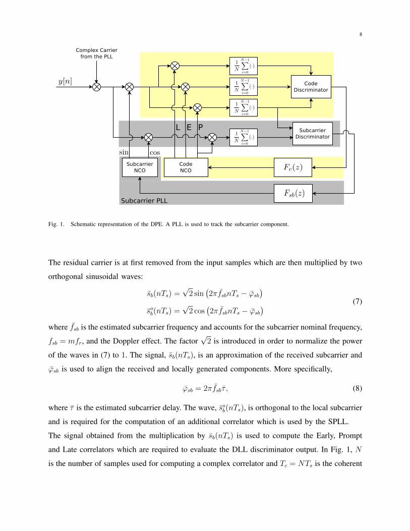
of the SLL introduced by [8], [9]. A schematic representation of the DPE is provided in Fig. 1.
The code component is tracked using a standard DLL whereas the subcarrier delay is recovered
using an additional PLL. The symbols Fc(z) and Fsb(z) in Fig. 1 denote the transfer functions of
the loop filters adopted for the processing of the delay and subcarrier components, respectively.
8
PEL
Subcarrier PLL
Fig. 1. Schematic representation of the DPE. A PLL is used to track the subcarrier component.
The residual carrier is at first removed from the input samples which are then multiplied by two
orthogonal sinusoidal waves:
s̄b(nTs) =√
2 sin(2πf̄sbnTs − ϕ̄sb
)s̄ob(nTs) =
√2 cos
(2πf̄sbnTs − ϕ̄sb
) (7)
where f̄sb is the estimated subcarrier frequency and accounts for the subcarrier nominal frequency,
fsb = mfr, and the Doppler effect. The factor√
2 is introduced in order to normalize the power
of the waves in (7) to 1. The signal, s̄b(nTs), is an approximation of the received subcarrier and
ϕ̄sb is used to align the received and locally generated components. More specifically,
ϕ̄sb = 2πf̄sbτ̄ , (8)
where τ̄ is the estimated subcarrier delay. The wave, s̄ob(nTs), is orthogonal to the local subcarrier
and is required for the computation of an additional correlator which is used by the SPLL.
The signal obtained from the multiplication by s̄b(nTs) is used to compute the Early, Prompt
and Late correlators which are required to evaluate the DLL discriminator output. In Fig. 1, N
is the number of samples used for computing a complex correlator and Tc = NTs is the coherent
9
integration time. The Early, Prompt and Late correlators are given by
P =1
N
N−1∑i=0
y[n]c (nTs − τ) s̄b(nTs) exp{−j2πfdnTs − jϕ}
E =1
N
N−1∑i=0
y[n]c (nTs − τ − ds/2) s̄b(nTs) exp{−j2πfdnTs − jϕ}
L =1
N
N−1∑i=0
y[n]c (nTs − τ + ds/2) s̄b(nTs) exp{−j2πfdnTs − jϕ}
(9)
where fd and ϕ are carrier frequency and phase estimated by the carrier PLL. τ is the code delay
estimated by the DLL at the previous iteration and ds is the Early-minus-Late chip spacing. The
correlators in (9) are used by the DLL as in standard GNSS receivers [22], [23] and for this
reason DLL operations are not discussed further.
The signal obtained from the multiplication by s̄ob(nTs) is used to compute an additional correlator
PQ =1
N
N−1∑i=0
y[n]c (nTs − τ) s̄ob(nTs) exp{−j2πfdnTs − jϕ}. (10)
Assuming perfect code and frequency synchronization, i.e, τ = τ0 and fd = f0, it is possible to
show that P and PQ can be expressed as
P =
√Cs1√
2d exp {j∆ϕ} sin (π∆fsbNTs)
N sin (π∆fsbTs)cos (π∆fsb(N − 1)Ts + ∆ϕsb) + ηP
PQ =
√Cs1√
2d exp {j∆ϕ} sin (π∆fsbNTs)
N sin (π∆fsbTs)sin (π∆fsb(N − 1)Ts + ∆ϕsb) + ηQ
(11)
where d models the effect of the navigation message1, s1 is the first coefficient of the series
expansion (5) and ∆ϕ = ϕ0 − ϕ is the residual phase to be estimated by the PLL. The residual
subcarrier frequency and phase are defined as
∆fsb = fsb − f̄sb (12)
∆ϕsb = 2πfsbτ0 − ϕ̄sb = 2π(fsbτ0 − f̄sbτ̄
)(13)
and need to be recovered by the SPLL. ηP and ηQ are two complex circularly symmetric
independent Gaussian random variables with zero mean and variance
Var {ηP} = Var {ηQ} =2
Nσ2. (14)
1it is assumed that d(·) takes a constant value over the integration period.
10
The independence of ηP and ηQ derives from the fact that they are the projections of ηBB[n]
over two orthogonal signals, s̄b(nTs) and s̄ob(nTs).
For a small residual subcarrier frequency error,
∆fsb ≈ 0,
the complex correlators (11) can be further simplified as
P =
√C
2s1d exp {j∆ϕ} cos (∆ϕs) + ηI
PQ =
√C
2s1d exp {j∆ϕ} sin (∆ϕs) + ηQ.
(15)
From (15), it is finally possible to design subcarrier discriminators able to generate the error
signal used by the SPLL to maintain lock and estimate the subcarrier parameters. In particular,
two classes of SPLL discriminators can be designed:
• coherent discriminators: the effect of the residual carrier phase is neglected (∆ϕ = 0) and
the SPLL operates assuming perfect carrier synchronization. This is the same hypothesis
adopted for coherent DLL discriminators [22].
• non-coherent discriminators: the subcarrier discriminator is designed to operate even in
the presence of residual carrier phase errors (∆ϕ 6= 0).
The design of SPLL discriminators is out of the scope of this paper and only two discriminator
examples are considered in the following. More specifically,
εc(∆ϕs) = arctan
(<{PQ}<{P}
)(16)
can be used as coherent discriminator. When ∆ϕ = 0, the signal components of P and PQ
are real and thus only the real parts of correlators (15) are used to compute the error signal, εc.
Discriminator (16) is analogous to the Costas discriminator used in standard PLL. Other coherent
discriminators can be obtained using different approximations for the arctangent function in (16).
A non-coherent discriminator can be obtained as
εnc(∆ϕs) = arctan
(<{PQP
}). (17)
The working principle of (17) can be intuitively understood by neglecting the noise components,
ηI and ηQ, in (15) and computing the ratio PQ
P. Under this hypothesis, it clearly emerges that
εnc is insensitive to residual carrier phase variations and equals ∆ϕs. The noise performance of
11
(16) and (17) are analyzed in Section IV.
The discriminator output is then filtered and a new estimate of the subcarrier frequency, f̄sb, is
produced. The transfer function of the SPLL loop filter is is denoted Fsb(z) in Fig. 1. Note that
the loop filter can be designed using standard techniques [22], [24]. As for standard PLLs, the
subcarrier residual phase, ∆ϕsb, is driven to zero by adjusting the estimated subcarrier frequency,
f̄sb. The new estimate of f̄sb is used by the Numerically Controlled Oscillator (NCO) of the SPLL
to generate the local subcarriers, s̄sb(·) and s̄osb(·), closing the subcarrier processing loop of the
DPE.
IV. PERFORMANCE ANALYSIS
In this section, the performance of the DPE are analyzed in terms of coherent output SNR
and tracking jitter. The coherent output SNR [21], [25] is the ratio between the signal and noise
power at the correlator output when the local signal replicas are perfectly aligned with the input
signal. The tracking jitter [19] quantifies the amount of noise transferred by a tracking loop
from the input signal to the final delay estimate. In this case, the tracking jitter of the SPLL is
compared with that of the SLL of the DE, showing the advantages of the DPE. The tracking
jitter of the SCC technique is also used as term of comparison.
A. Coherent Output SNR
The coherent output SNR is defined as [21], [25]:
SNRq = maxτ,fd,τ̄
|E {P}|212Var {P}
(18)
where the factor 12
accounts for the fact that P is a complex quantity and only the power of its
real part is considered. Using (15) and (14), it this possible to evaluate (18) when the sinusoidal
subcarrier (7) is used to compute the prompt correlator:
SNRq =C
1NN0BRx
s21
2. (19)
The term s212
is the square modulus of the correlation between the input filtered subcarrier and
s̄b(nTs), when the signal and estimated delays are aligned:
∣∣R̄(0)∣∣2 =
∣∣∣∣∣ 1
N
N−1∑n=0
s̃b (nTs − τ0) s̄b(nTs)
∣∣∣∣∣2
τ̄=τ0
=s2
1
2. (20)
12
The DE adopts a local subcarrier equal to the unfiltered ideal subcarrier sb (nTs − τ̄). In this
case, the coherent output SNR assumes the following form
SNRid =C
1NN0BRx
∣∣∣R̃(0)∣∣∣2 (21)
where ∣∣∣R̃(0)∣∣∣2 =
∣∣∣∣∣ 1
N
N−1∑n=0
s̃b (nTs − τ0) sb (nTs − τ0)
∣∣∣∣∣2
. (22)
The loss experienced when using a sinusoidal wave for recovering the signal subcarrier is thus
given by the ratio between (20) and (22):
Lo =
∣∣R̄(0)∣∣2∣∣∣R̃(0)∣∣∣2 . (23)
The worst case scenario occurs when s̃b(t) = sb(t) and
Lo =s2
1
2. (24)
In the case of BOC subcarriers, sb(t), is a perfect square wave and s1 = 4π
. In this way, the
worst loss which may be experienced is
Lo =8
π2→ Lo|dB = −0.91 dB (25)
that is less than 1 dB. Loss (25) is the same experienced by a GNSS receiver when processing
the incoming carrier using a square wave approximation [26]. Note that Lo can become a gain
when the signal is heavily filtered and s̃b (t) is more similar to a sinusoidal wave than to the ideal
subcarrier. In this case, the correlation performed using a sinusoidal local subcarrier provides a
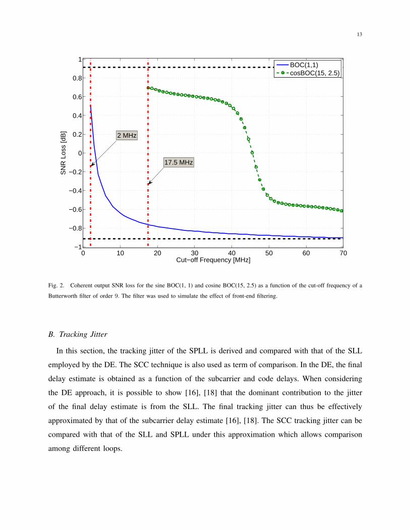
better approximation of a filter matched to the input signal. This fact clearly emerges in Fig. 2
where the coherent output SNR loss is shown as a function of the front-end bandwidth. More
specifically, a 9th order Butterworth filter was used to simulate the impact of front-end filtering
and Lo was evaluated as a function of its cut-off frequency. The cases of sine BOC(1, 1) and
cosine BOC(15, 2.5) are considered. From Fig. 2 it emerges that the DPE provides a gain for
the processing of wide-band BOC modulated signals. This is the case of the cosine BOC(15,
2.5) modulation adopted for the Galileo PRS: a front-end with a total bandwidth greater than 45
MHz is required to obtain an actual loss. Note that signal band-limiting can also be introduced at
the transmitter side. For example, the cosine BOC(15, 2.5) transmitted by the GIOVE-B satellite
was characterized by a bandwidth of about 40 MHz [27]. In this case, the DPE will always
provided better performance with respect to standard techniques.
13
0 10 20 30 40 50 60 70−1
−0.8
−0.6
−0.4
−0.2
0
0.2
0.4
0.6
0.8
1
Cut−off Frequency [MHz]
SN
R L
oss
[dB
]
2 MHz
17.5 MHz
BOC(1,1)cosBOC(15, 2.5)
Fig. 2. Coherent output SNR loss for the sine BOC(1, 1) and cosine BOC(15, 2.5) as a function of the cut-off frequency of a
Butterworth filter of order 9. The filter was used to simulate the effect of front-end filtering.
B. Tracking Jitter
In this section, the tracking jitter of the SPLL is derived and compared with that of the SLL
employed by the DE. The SCC technique is also used as term of comparison. In the DE, the final
delay estimate is obtained as a function of the subcarrier and code delays. When considering
the DE approach, it is possible to show [16], [18] that the dominant contribution to the jitter
of the final delay estimate is from the SLL. The final tracking jitter can thus be effectively
approximated by that of the subcarrier delay estimate [16], [18]. The SCC tracking jitter can be
compared with that of the SLL and SPLL under this approximation which allows comparison
among different loops.
14
The tracking jitter can be computed as [23]
στ =σdGd
√2BeqTc (26)
where σd is the standard deviation of the discriminator output, Beq is the loop equivalent band-
width and Tc is the coherent integration time introduced in Section III. Gd is the discriminator
gain defined as
Gd =∂E [S(τ)]
∂τ
∣∣∣∣τ=0
(27)
where S(·) is the discriminator input-output function. S(·) depends on the type of discriminator
and can be computed using definitions (16) and (17) and correlator model (15). In both coherent
and non-coherent case, it is possible to show
S(τ) = 2πfsbτ + ητ (28)
where ητ is a zero mean residual noise term the statistics of which depend on the type of
discriminator. For the coherent discriminator, (16), the tracking jitter can be computed using an
approach similar to that developed in [28] for the evaluation of the normalized standard deviation
at the output of an arctangent discriminator. In particular, it is possible to show that
σdGd
=1
2πfsb
√SNRq + 1
SNR2q
=1
2πfsb
√√√√ 1C
1NN0BRx
Lo
(1 +
1C
1NN0BRx
Lo
). (29)
The normalization factor, 12πfsb
, is used to express the normalized standard deviation in units
of seconds accounting for the fact that the output of (16) is in units of cycles. From (29), it is
finally possible to compute the tracking jitter of the coherent discriminator:
στ =1
2πfsb
√√√√√ 2BeqTcC
1NN0BRx
s212
1 +1
C1NN0BRx
s212
≈ 1
2πfsb
√√√√ Beq
CN0
s212
(1 +
1
2 CN0Tc
s212
)(30)
where the last approximation was obtained exploiting the hypothesis
BRx ≈fs2
=1
2Ts→ 1
NBRx ≈
1
2NTs=
1
2Tc. (31)
The tracking jitter for the non-coherent discriminator can be computed using the approach
described in Appendix I where it is shown that for high coherent output SNR values, the non-
coherent discriminator is equivalent to the coherent one after that the residual carrier phase error
has been compensated for. Given the equivalence of these two discriminators for a high coherent
15
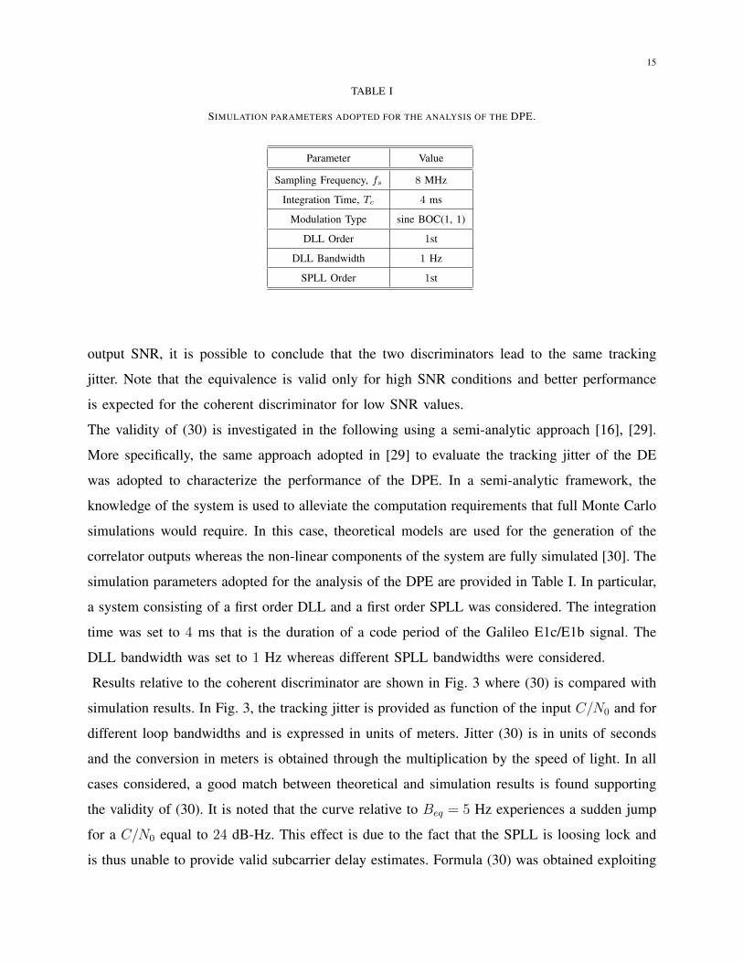
TABLE I
SIMULATION PARAMETERS ADOPTED FOR THE ANALYSIS OF THE DPE.
Parameter Value
Sampling Frequency, fs 8 MHz
Integration Time, Tc 4 ms
Modulation Type sine BOC(1, 1)
DLL Order 1st
DLL Bandwidth 1 Hz
SPLL Order 1st
output SNR, it is possible to conclude that the two discriminators lead to the same tracking
jitter. Note that the equivalence is valid only for high SNR conditions and better performance
is expected for the coherent discriminator for low SNR values.
The validity of (30) is investigated in the following using a semi-analytic approach [16], [29].
More specifically, the same approach adopted in [29] to evaluate the tracking jitter of the DE
was adopted to characterize the performance of the DPE. In a semi-analytic framework, the
knowledge of the system is used to alleviate the computation requirements that full Monte Carlo
simulations would require. In this case, theoretical models are used for the generation of the
correlator outputs whereas the non-linear components of the system are fully simulated [30]. The
simulation parameters adopted for the analysis of the DPE are provided in Table I. In particular,
a system consisting of a first order DLL and a first order SPLL was considered. The integration
time was set to 4 ms that is the duration of a code period of the Galileo E1c/E1b signal. The
DLL bandwidth was set to 1 Hz whereas different SPLL bandwidths were considered.
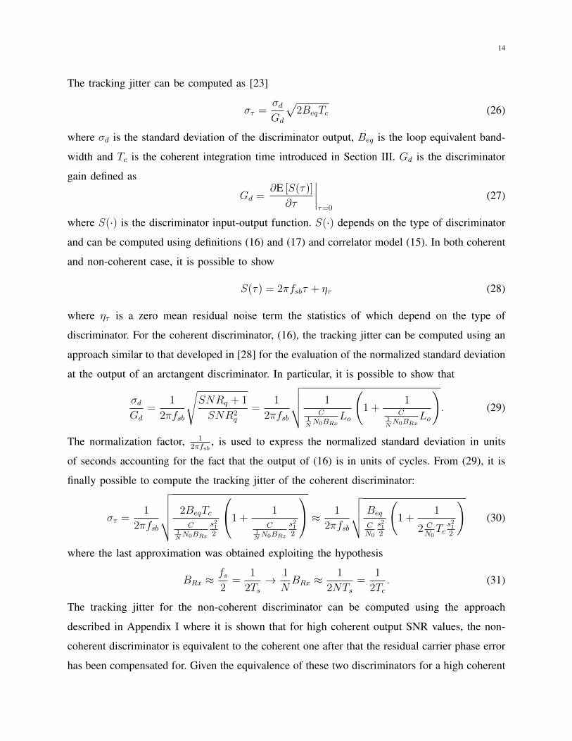
Results relative to the coherent discriminator are shown in Fig. 3 where (30) is compared with
simulation results. In Fig. 3, the tracking jitter is provided as function of the input C/N0 and for
different loop bandwidths and is expressed in units of meters. Jitter (30) is in units of seconds
and the conversion in meters is obtained through the multiplication by the speed of light. In all
cases considered, a good match between theoretical and simulation results is found supporting
the validity of (30). It is noted that the curve relative to Beq = 5 Hz experiences a sudden jump
for a C/N0 equal to 24 dB-Hz. This effect is due to the fact that the SPLL is loosing lock and
is thus unable to provide valid subcarrier delay estimates. Formula (30) was obtained exploiting
16
20 25 30 35 400
2
4
6
8
10
12
14
16
18
20SPLL - Coherent Discriminator
C/N0 [dB-Hz]
Tra
ckin
g J
itte
r [m
]
Beq = 1 Hz
Beq = 2 Hz
Beq = 5 Hz
Loss of Lock
Simulation
Theory
Fig. 3. Tracking jitter of the SPLL with coherent discriminator for different loop bandwidths. Comparison between simulations
and theoretical results.
a linear approximation of the loop and thus is unable to predict non-linear phenomena such as
loss of lock. Lower equivalent bandwidths better shield the loop against the input noise and loss
of lock does not occur. Deviations of the simulation curves from theoretical results at low C/N0
values are also due to non-linear effects which are not accounted by (30) [29].
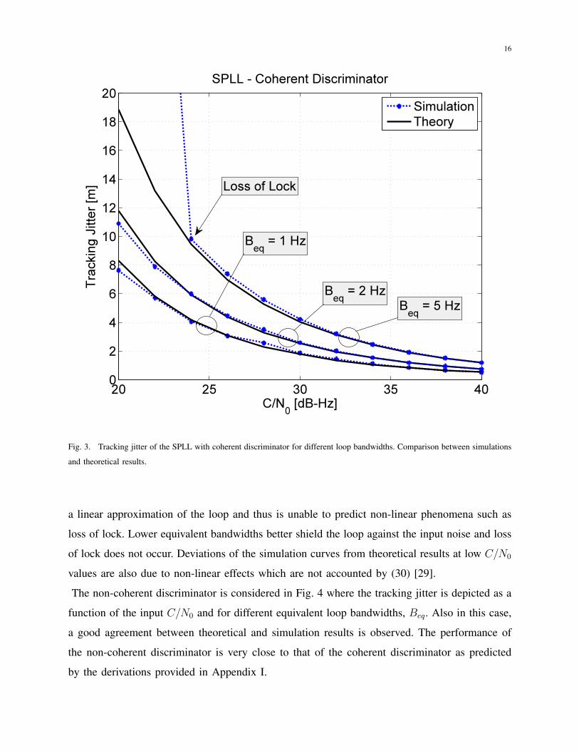
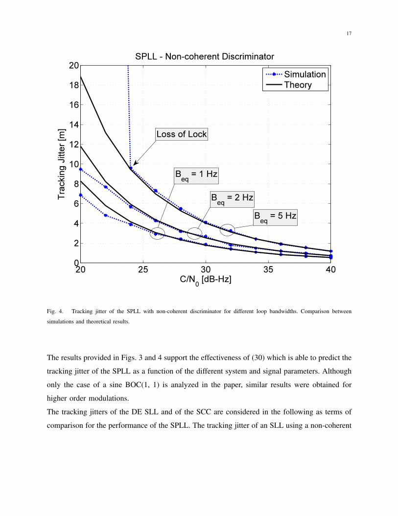
The non-coherent discriminator is considered in Fig. 4 where the tracking jitter is depicted as a
function of the input C/N0 and for different equivalent loop bandwidths, Beq. Also in this case,
a good agreement between theoretical and simulation results is observed. The performance of
the non-coherent discriminator is very close to that of the coherent discriminator as predicted
by the derivations provided in Appendix I.
17
20 25 30 35 400
2
4
6
8
10
12
14
16
18
20SPLL - Non-coherent Discriminator
C/N0 [dB-Hz]
Tra
ckin
g J
itte
r [m
]
Beq = 1 Hz
Beq = 2 Hz
Beq = 5 Hz
Loss of Lock
Simulation
Theory
Fig. 4. Tracking jitter of the SPLL with non-coherent discriminator for different loop bandwidths. Comparison between
simulations and theoretical results.
The results provided in Figs. 3 and 4 support the effectiveness of (30) which is able to predict the
tracking jitter of the SPLL as a function of the different system and signal parameters. Although
only the case of a sine BOC(1, 1) is analyzed in the paper, similar results were obtained for
higher order modulations.
The tracking jitters of the DE SLL and of the SCC are considered in the following as terms of
comparison for the performance of the SPLL. The tracking jitter of an SLL using a non-coherent
18
20 22 24 26 28 30 32 34 36 38 400
5
10
15
20
25
Beq
= 1 Hz, BOC(1, 1)
C/N0 [dB-Hz]
Tra
ckin
g J
itte
r [m
]
SPLL, theory
SLL, ds = 0.1
SLL, ds = 0.25
SLL, ds = 0.4
SCC, ds = 0.4
SCC, ds = 0.25
SCC, ds = 0.1
Simulation
Theory
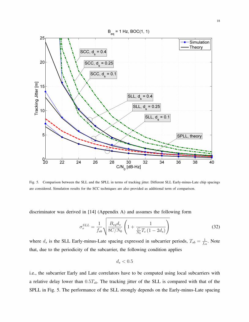
Fig. 5. Comparison between the SLL and the SPLL in terms of tracking jitter. Different SLL Early-minus-Late chip spacings
are considered. Simulation results for the SCC techniques are also provided as additional term of comparison.
discriminator was derived in [14] (Appendix A) and assumes the following form
σSLLτ =1
fsb
√√√√ Beqds8C/N0
(1 +
1CN0Tc (1− 2ds)
)(32)
where ds is the SLL Early-minus-Late spacing expressed in subcarrier periods, Tsb = 1fsb
. Note
that, due to the periodicity of the subcarrier, the following condition applies
ds < 0.5
i.e., the subcarrier Early and Late correlators have to be computed using local subcarriers with
a relative delay lower than 0.5Tsb. The tracking jitter of the SLL is compared with that of the
SPLL in Fig. 5. The performance of the SLL strongly depends on the Early-minus-Late spacing
19
adopted: for narrow ds, the SLL outperforms the SPLL which becomes preferable for ds greater
than 0.25. For ds = 0.25, the SLL and SPLL have similar performance as predicted by (30) and
(32) when Lo =s212
= 8π2 . It is noted that a narrow ds reduces the ability of the SLL to recover
large initial delay errors and strongly impacts the transient behavior of the loop. The transient
analysis of SLL and SPLL is beyond the scope of this paper.
Fig. 5 also provides the tracking jitter of the DLL of the SCC technique. Since no theoretical
results are currently available on the SCC tracking jitter [12], [13], [15], only simulation results
are presented. The algorithm detailed in [13] was implemented and used for the analysis: SCC
also requires the computation of Early and Late subcarrier correlators and the performance of
the loop strongly depends on the Early-minus-Late chip spacing, ds. From the results provided
in Fig. 5, it emerges that the SPLL achieves performance similar to that of the SLL even if it
requires a lower computational load. Note that the analysis presented above assumed ideal front-
end filtering. Under this condition, the SLL achieves its best performance whereas the SPLL
experiences the worst loss. Even in this case, the SPLL achieves satisfactory performance in
terms of tracking jitter. Improved performance is expected in the presence of front-end filtering.
The SCC is always outperformed by the other techniques as already remarked by [15]. This fact
is expected and is due to the subcarrier removal operated by the SCC technique. Although the
SCC uses a sinusoidal representation of the subcarrier, its performance is significantly worse
than that of the DPE.
V. REAL DATA ANALYSIS
In the previous section, the performance of the DPE was analyzed in terms of coherent output
SNR and tracking jitter. Semi-analytic simulations were also used to support the validity of
theoretical results. In this section, real data collected using a wide-band Radio Frequency Signal
Analyzer (RFSA) are used to demonstrate the feasibility of the proposed tracking technique and
further investigate the performance of the DPE. More specifically, a National Instruments (NI)
PXI-e 5663 vector signal analyzer was used to collect data from the GIOVE-B satellite. It is
noted that the GIOVE-B satellite was decommissioned in the Summer 2012 and that the data
set used in this paper was collected on 5th November 2011. The use of such data set is justified
by the fact that it contains valid cosine BOC(15, 2.5) data with a known Pseudo Random Noise
(PRN) code [31]. Thus, the use of this data set allows one to test the DPE for both the sine
20
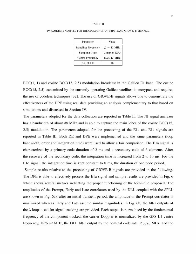
TABLE II
PARAMETERS ADOPTED FOR THE COLLECTION OF WIDE-BAND GIOVE-B SIGNALS.
Parameter Value
Sampling Frequency fs = 40 MHz
Sampling Type Complex I&Q
Centre Frequency 1575.42 MHz
No. of bits 16
BOC(1, 1) and cosine BOC(15, 2.5) modulation broadcast in the Galileo E1 band. The cosine
BOC(15, 2.5) transmitted by the currently operating Galileo satellites is encrypted and requires
the use of codeless techniques [32]. The use of GIOVE-B signals allows one to demonstrate the
effectiveness of the DPE using real data providing an analysis complementary to that based on
simulations and discussed in Section IV.
The parameters adopted for the data collection are reported in Table II. The NI signal analyzer
has a bandwidth of about 38 MHz and is able to capture the main lobes of the cosine BOC(15,
2.5) modulation. The parameters adopted for the processing of the E1a and E1c signals are
reported in Table III. Both DE and DPE were implemented and the same parameters (loop
bandwidth, order and integration time) were used to allow a fair comparison. The E1a signal is
characterized by a primary code duration of 2 ms and a secondary code of 5 elements. After
the recovery of the secondary code, the integration time is increased from 2 to 10 ms. For the
E1c signal, the integration time is kept constant to 8 ms, the duration of one code period.
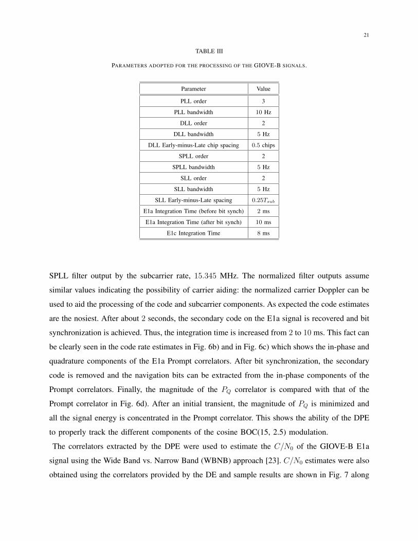
Sample results relative to the processing of GIOVE-B signals are provided in the following.
The DPE is able to effectively process the E1a signal and sample results are provided in Fig. 6
which shows several metrics indicating the proper functioning of the technique proposed. The
amplitudes of the Prompt, Early and Late correlators used by the DLL coupled with the SPLL
are shown in Fig. 6a): after an initial transient period, the amplitude of the Prompt correlator is
maximized whereas Early and Late assume similar magnitudes. In Fig. 6b) the filter outputs of
the 3 loops used for signal tracking are provided. Each output is normalized by the fundamental
frequency of the component tracked: the carrier Doppler is normalized by the GPS L1 centre
frequency, 1575.42 MHz, the DLL filter output by the nominal code rate, 2.5575 MHz, and the
21
TABLE III
PARAMETERS ADOPTED FOR THE PROCESSING OF THE GIOVE-B SIGNALS.
Parameter Value
PLL order 3
PLL bandwidth 10 Hz
DLL order 2
DLL bandwidth 5 Hz
DLL Early-minus-Late chip spacing 0.5 chips
SPLL order 2
SPLL bandwidth 5 Hz
SLL order 2
SLL bandwidth 5 Hz
SLL Early-minus-Late spacing 0.25Tsub
E1a Integration Time (before bit synch) 2 ms
E1a Integration Time (after bit synch) 10 ms
E1c Integration Time 8 ms
SPLL filter output by the subcarrier rate, 15.345 MHz. The normalized filter outputs assume
similar values indicating the possibility of carrier aiding: the normalized carrier Doppler can be
used to aid the processing of the code and subcarrier components. As expected the code estimates
are the nosiest. After about 2 seconds, the secondary code on the E1a signal is recovered and bit
synchronization is achieved. Thus, the integration time is increased from 2 to 10 ms. This fact can
be clearly seen in the code rate estimates in Fig. 6b) and in Fig. 6c) which shows the in-phase and
quadrature components of the E1a Prompt correlators. After bit synchronization, the secondary
code is removed and the navigation bits can be extracted from the in-phase components of the
Prompt correlators. Finally, the magnitude of the PQ correlator is compared with that of the
Prompt correlator in Fig. 6d). After an initial transient, the magnitude of PQ is minimized and
all the signal energy is concentrated in the Prompt correlator. This shows the ability of the DPE
to properly track the different components of the cosine BOC(15, 2.5) modulation.
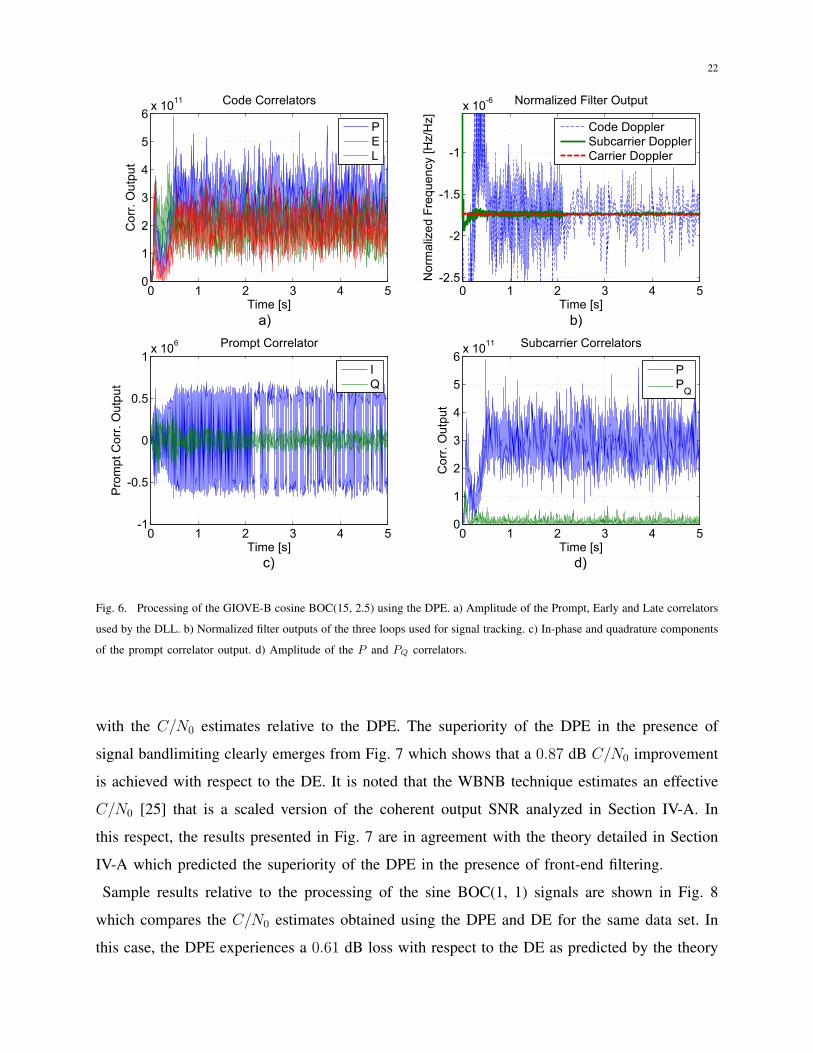
The correlators extracted by the DPE were used to estimate the C/N0 of the GIOVE-B E1a
signal using the Wide Band vs. Narrow Band (WBNB) approach [23]. C/N0 estimates were also
obtained using the correlators provided by the DE and sample results are shown in Fig. 7 along
22
0 1 2 3 4 50
1
2
3
4
5
6xN10
11
TimeN[s]
Co
rr)NO
utp
ut
CodeNCorrelators
PEL
0 1 2 3 4 5Q2)5
Q2
Q1)5
Q1
xN10Q6
TimeN[s]
No
rma
lize
dNF
req
ue
ncy
N[Hz/
Hz]
NormalizedNFilterNOutput
CodeNDopplerSubcarrierNDopplerCarrierNDoppler
0 1 2 3 4 5Q1
Q0)5
0
0)5
1xN10
6
TimeN[s]
Pro
mp
tNCo
rr)NO
utp
ut
PromptNCorrelator
IQ
0 1 2 3 4 50
1
2
3
4
5
6xN10
11
TimeN[s]
Co
rr)NO
utp
ut
SubcarrierNCorrelators
PP
Q
aD bD
cD dD
Fig. 6. Processing of the GIOVE-B cosine BOC(15, 2.5) using the DPE. a) Amplitude of the Prompt, Early and Late correlators
used by the DLL. b) Normalized filter outputs of the three loops used for signal tracking. c) In-phase and quadrature components
of the prompt correlator output. d) Amplitude of the P and PQ correlators.
with the C/N0 estimates relative to the DPE. The superiority of the DPE in the presence of
signal bandlimiting clearly emerges from Fig. 7 which shows that a 0.87 dB C/N0 improvement
is achieved with respect to the DE. It is noted that the WBNB technique estimates an effective
C/N0 [25] that is a scaled version of the coherent output SNR analyzed in Section IV-A. In
this respect, the results presented in Fig. 7 are in agreement with the theory detailed in Section
IV-A which predicted the superiority of the DPE in the presence of front-end filtering.
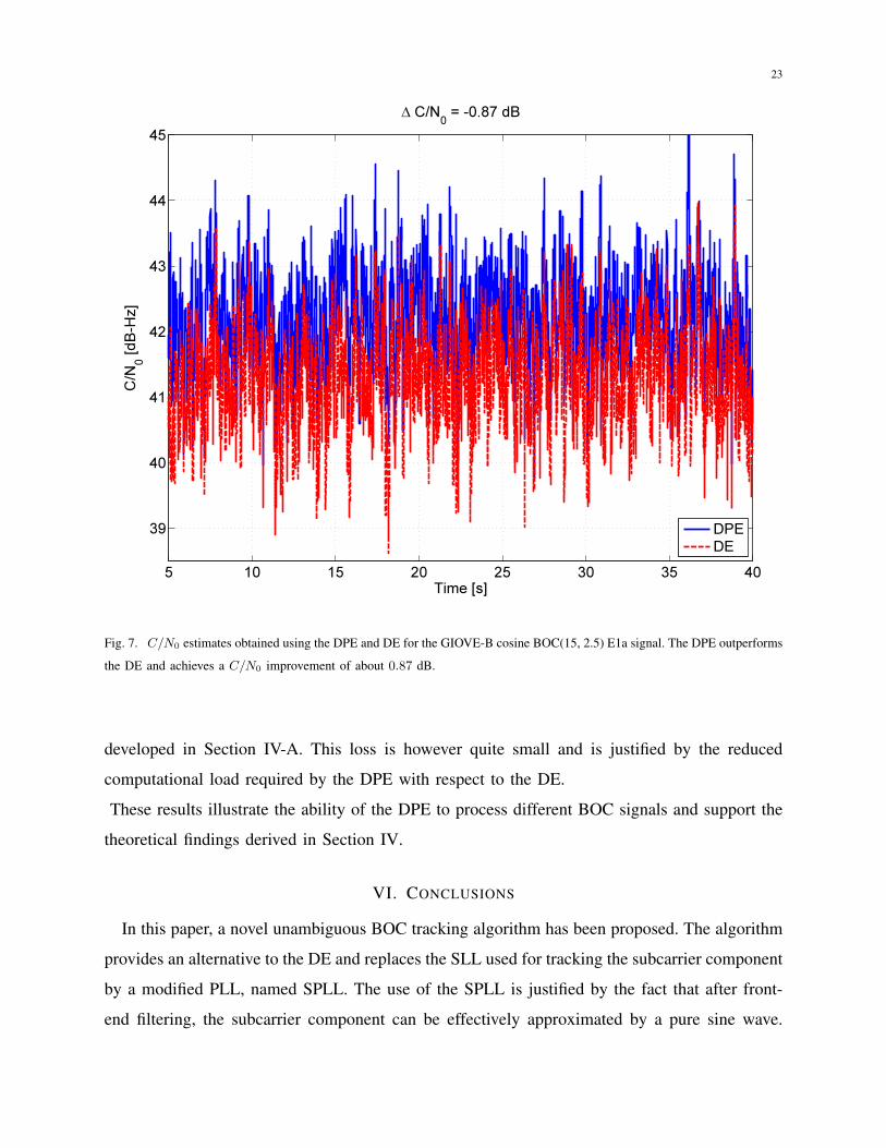
Sample results relative to the processing of the sine BOC(1, 1) signals are shown in Fig. 8
which compares the C/N0 estimates obtained using the DPE and DE for the same data set. In
this case, the DPE experiences a 0.61 dB loss with respect to the DE as predicted by the theory
23
5 10 15 20 25 30 35 40
39
40
41
42
43
44
45
∆ C/N0 = -0.87 dB
Time [s]
C/N
0 [
dB
-Hz]
DPE
DE
Fig. 7. C/N0 estimates obtained using the DPE and DE for the GIOVE-B cosine BOC(15, 2.5) E1a signal. The DPE outperforms
the DE and achieves a C/N0 improvement of about 0.87 dB.
developed in Section IV-A. This loss is however quite small and is justified by the reduced
computational load required by the DPE with respect to the DE.
These results illustrate the ability of the DPE to process different BOC signals and support the
theoretical findings derived in Section IV.
VI. CONCLUSIONS
In this paper, a novel unambiguous BOC tracking algorithm has been proposed. The algorithm
provides an alternative to the DE and replaces the SLL used for tracking the subcarrier component
by a modified PLL, named SPLL. The use of the SPLL is justified by the fact that after front-
end filtering, the subcarrier component can be effectively approximated by a pure sine wave.
24
15 20 25 30 35 4038
38.5
39
39.5
40
40.5
∆ C/N0 = 0.61 dB
Time [s]
C/N
0 [
dB
-Hz]
DPE
DE
Fig. 8. C/N0 estimates obtained using the DPE and DE for the GIOVE-B BOC(1, 1) E1c signal. The DPE experiences a 0.61
dB loss with respect to the DE.
The algorithm proposed, the DPE, if thoroughly characterized and its performance is determined
under different operating conditions. In particular, it shown that the DPE outperforms the DE
in the presence of front-end filtering. Theoretical results are supported by simulations and the
effectiveness of the technique proposed is demonstrated by processing real wide-band BOC
signals. The good agreement between theoretical, simulation and experimental results supports
the validity of the findings presented. Finally, the DPE requires a lower computational load than
the DE and thus should be preferred for example for the processing of wide-band signals such
as the cosine BOC(15, 2.5) modulation.
25
APPENDIX I
NON-COHERENT DISCRIMINATOR
In this appendix, the properties of the non-coherent discriminator, (17), are briefly investigated.
In particular, it is shown that for high coherent output SNR values, (17) is equivalent to the
coherent discriminator, (16), after that the residual carrier phase, ∆ϕ, has been compensated for.
The non-coherent discriminator, (17), is defined as the arctangent of
<{PQP
}(33)
which can be expressed as
<{PQP
}= <
{PQ exp {−j∆ϕ}P exp {−j∆ϕ}
}= <
{<{PQ exp {−j∆ϕ}}< {P exp {−j∆ϕ}}
1 + jρQ1 + jρ
}=<{PQ exp {−j∆ϕ}}< {P exp {−j∆ϕ}}
<{
1 + jρQ1 + jρ
}=<{PQ exp {−j∆ϕ}}< {P exp {−j∆ϕ}}
< {(1 + jρQ) (1− jρ)} 1
1 + ρ2
=<{PQ exp {−j∆ϕ}}< {P exp {−j∆ϕ}}
(1 + ρQρ)1
1 + ρ2.
(34)
where
ρQ =={PQ exp {−j∆ϕ}}< {PQ exp {−j∆ϕ}}
ρ =={P exp {−j∆ϕ}}< {P exp {−j∆ϕ}}
. (35)
Note that for high coherent output SNR values, i.e., when the signal component in (15) is
dominant,
ρ� 1
and the last fraction in (34) can be expanded as a geometric series. In this way, (33) can be
expressed as
<{PQP
}=<{PQ exp {−j∆ϕ}}< {P exp {−j∆ϕ}}
(1 + ρQρ)+∞∑i=0
(−ρ2
)i=<{PQ exp {−j∆ϕ}}< {P exp {−j∆ϕ}}
[1 +
+∞∑i=1
(−ρ2
)i+ ρQρ
+∞∑i=0
(−ρ2
)i].
(36)
If only the constant term in (36) is retained, the following approximation is finally obtained:
<{PQP
}≈ <{PQ exp {−j∆ϕ}}< {P exp {−j∆ϕ}}
. (37)
26
The truncation in (37) is justified by the hypothesis of a high coherent output SNR. Approxima-
tion (37) shows that, for high SNR values, the non-coherent discriminator is equivalent to the
coherent discriminator after that the residual carrier phase error has been compensated for. For
this reason, the coherent and non-coherent discriminators have the same tracking jitter for high
SNR values.
REFERENCES
[1] Titus, B., Betz, J., Hegarty, C., Owen, R.: ‘Intersystem and intrasystem interference analysis methodology’. Proc. of the
16th International Technical Meeting of the Satellite Division of The Institute of Navigation (ION GPS/GNSS), Portland,
OR , September 2003, pp. 2061 – 2069
[2] ITU: ‘Recommendation ITU-R M.1831, a coordination methodology for RNSS inter-system interference estimation’, 2007
[3] Betz, J.W.: ‘Binary offset carrier modulations for radionavigation’. NAVIGATION, the Journal of the Institute of Navigation,
Winter 2001, 48, (4), pp. 227–246
[4] Rebeyrol, E., Julien, O., Macabiau, C., Ries, L., Delatour, A., Lestarquit, L.: ‘Galileo civil signal modulations’. GPS
Solutions, 2007, 11, pp. 159–171. ISSN 1080-5370
[5] Fine, P., Wilson, W.: ‘Tracking algorithm for GPS offset carrier signal’. Proc. of the National Technical Meeting of The
Institute of Navigation, San Diego, CA, January 1999, pp. 671–676
[6] Julien, O., Macabiau, C., Cannon, M., Lachapelle, G.: ‘ASPeCT: unambiguous sine-boc(n,n) acquisition/tracking technique
for navigation applications’. IEEE Trans. Aerosp. Electron. Syst., January 2007, 43, (1), pp. 150–162
[7] Burian, A., Lohan, E., Renfors, M.K.: ‘Efficient delay tracking methods with sidelobes cancellation for BOC-modulated
signals’. EURASIP Journal on Wireless Communications Networking, 2007, page 20. Article ID 72626
[8] Hodgart, M., Blunt, P.: ‘Dual estimate receiver of binary offset carrier modulated signals for global navigation satellite
systems’. Electronics Letters, 2 2007, 43, (16), pp. 877 –878. ISSN 0013-5194. doi:10.1049/el:20071101
[9] Hodgart, M.S., Blunt, P., Unwin, M.: ‘The optimal dual estimate solution for robust tracking of binary offset carrier (BOC)
modulation’. Proc. of the 20th International Technical Meeting of the Satellite Division of The Institute of Navigation
(ION GNSS), Fort Worth, TX, September 2007, pp. 1017–1027
[10] Anantharamu, P., Borio, D., Lachapelle, G.: ‘Sub-carrier shaping for BOC modulated GNSS signals’. EURASIP Journal
on Advances in Signal Processing, 2011, 133, (1), pp. 1–18. ISSN 1687-6180. doi:10.1186/1687-6180-2011-133
[11] Lohan, E., Burian, A., Renfors, M.: ‘Low-complexity unambiguous acquisition methods for BOC-modulated CDMA
signals’. International Journal of Satellite Communications and Networking, October 2008, 26, (6), pp. 503–522
[12] Ward, P.W.: ‘A design technique to remove the correlation ambiguity in binary offset carrier (BOC) spread spectrum
signals’. Proc. of the National Technical Meeting of The Institute of Navigation, San Diego, CA, January 2004, pp.
886–896
[13] Ward, P.W., Lillo, W.E.: ‘Ambiguity removal method for any GNSS binary offset carrier (BOC) modulation’. Proc. of the
International Technical Meeting of The Institute of Navigation, Anaheim, CA, January 2009, pp. 406–419
[14] Anantharamu, P.: Space-Time Equalization Techniques for New GNSS Signals. Phd thesis, Schulisch School of Engineering,
University of Calgary, September 2011
[15] Wendel, J., Hager, S.: ‘A robust technique for unambiguous BOC tracking’. Proc. of the 26th International Technical
Meeting of the Satellite Division of The Institute of Navigation (ION GNSS+), Nashville, TN, September 2013, pp. 1–12
27
[16] Anantharamu, P., Borio, D., Lachapelle, G.: ‘Pre-filtering, side-peak rejection and mapping: Several solutions for
unambiguous BOC tracking’. Proc. of the 22nd International Technical Meeting of The Satellite Division of the Institute
of Navigation (ION GNSS), Savannah, GA, September 2009, pp. 3142–3155
[17] Palestini, C.: Synchronization and Detection Techniques for Navigation and Communication Systems. Phd thesis, University
of Bologna, March 2010
[18] Ren, J., Jia, W., Chen, H., Yao, M.: ‘Unambiguous tracking method for alternative binary offset carrier modulated signals
based on dual estimate loop’. IEEE Commun. Lett., November 2012, 16, (11), pp. 1737–1740
[19] Van Dierendonck, A.J., Fenton, P., Ford, T.: ‘Theory and performance of narrow correlator spacing in a GPS receiver’.
NAVIGATION: Journal of the Institute of Navigation, Fall 1992, 39, (3), pp. 265 –283
[20] Betz, J.W., Kolodziejski, K.R.: ‘Generalized theory of code tracking with an early-late discriminator part I: Lower bound
and coherent processing’. IEEE Trans. Aerosp. Electron. Syst., October 2009, 45, (4), pp. 1538–1556. ISSN 0018-9251.
doi:10.1109/TAES.2009.5310316
[21] Borio, D.: ‘A statistical theory for gnss signal acquisition’. PhD Thesis, Politecnico di Torino, 2008
[22] Kaplan, E.D., Hegarty, C., editors. Understanding GPS: Principles and Applications. Artech House Publishers, Norwood,
MA, USA 2005, 2nd edition
[23] Van Dierendonck, A.: ‘Ch. 5, GPS receivers’. In B.W. Parkinson, J.J. Spilker Jr., editors, Global Positioning System Theory
and Applications, volume 1. American Institute of Aeronautics & Astronautics 1996, pp. 329–407
[24] Stephens, S.A., Thomas, J.B.: ‘Controlled-root formulation for digital phase-locked loops’. IEEE Trans. Aerosp. Electron.
Syst., January 1995, 31, (1), pp. 78–95
[25] Betz, J.W.: ‘Effect of partial-band interference on receiver estimation of C/N0: Theory’. Proc. of the National Technical
Meeting of The Institute of Navigation, Long Beach, CA, January 2001, pp. 817–828
[26] Borio, D.: ‘Square wave decomposition for fast correlation in DSSS receivers’. IEEE Trans. Aerosp. Electron. Syst., April
2013, 49, (2), pp. 969–981. ISSN 0018-9251. doi:10.1109/TAES.2013.6494393
[27] Gatti, G., Falcone, M., Alpe, V., Malik, M., Burger, T., Rapisarda, M., Rooney, E.: ‘GIOVE-B chilbolton in-orbit test:
Initial results from the second galileo satellite’. Inside GNSS, September/October 2008, 3, (6), pp. 30–35
[28] Borio, D.: ‘Squaring and cross-correlation codeless tracking: analysis and generalisation’. IET Radar, Sonar & Navigation,
December 2011, 5, (9), pp. 958 –969
[29] Borio, D., Anantharamu, P., Lachapelle, G.: ‘SATLSim: a semi-analytic framework for fast GNSS tracking loop
simulations’. GPS Solutions, 2011, 15, pp. 427–431. ISSN 1080-5370
[30] Borio, D., Cano, E.: MATLAB - A Fundamental Tool for Scientific Computing and Engineering Applications - Volume
2, chapter 13, Semi-Analytic Techniques for Fast MATLAB Simulations. InTech 2012, pp. 285–310
[31] Galileo Project Office: GIOVE-A + B Navigation Signal-in-Space Interface Control Document. European Space Agency,
ESTEC Keplerlaan 1 - 2201 AZ Noordwijk - The Netherlands, August 2008
[32] Borio, D., Rao, M., O’Driscoll, C.: ‘Codeless processing of binary offset carrier modulated signals’. IET Radar, Sonar
and Navigation, February 2013, 7, (2), pp. 143–152