Embed Size (px)
Citation preview
UMA Architecture (Stage 2) R1.0.1 (2004-10-08)
Technical Specification
Unlicensed Mobile Access (UMA);
Architecture (Stage 2);
2004, Alcatel, AT&T Wireless Services, Inc., BT PLC, Cingular Wireless LLC, Ericsson AB, Kineto Wireless Inc., Motorola, Inc., Nokia, Nortel Networks, O2, Rogers Wireless Inc., Siemens AG, Sony Ericsson, T-Mobile USA.
THESE MATERIALS ARE PROVIDED ON AN "AS IS" BASIS. ALL WARRANTIES OF ANY KIND, WHETHER EXPRESS OR IMPLIED, ARE EXPRESSLY DISCLAIMED.
These documents may contain Intellectual Property Rights for which licenses must be obtained from companies participating with Unlicensed Mobile Access or third parties.
© 2004, Alcatel, AT&T Wireless Services, Inc., BT PLC, Cingular Wireless LLC, Ericsson AB, Kineto Wireless Inc., Motorola, Inc., Nokia, Nortel Networks, O2, Rogers Wireless Inc., Siemens AG, Sony Ericsson, T-Mobile USA.
THESE MATERIALS ARE PROVIDED ON AN "AS IS" BASIS. ALL WARRANTIES OF ANY KIND, WHETHER EXPRESS OR IMPLIED, ARE EXPRESSLY DISCLAIMED.
These documents may contain Intellectual Property Rights for which licenses must be obtained from companies participating with Unlicensed Mobile Access or third parties.
UMA Architecture (Stage 2) R1.0.1 (2004-10-08)2
Terms of Use
This document is provided according to the terms expressed at the UMA website, and are summarized here.
This document is copyright protected and may contain intellectual property rights (“IPR”) for which licenses must be obtained from the Participating Companies or third parties. You may not copy, modify, rent, lease, loan, sell, assign, distribute, license, reverse engineer or create derivative works based on this document.
Alcatel, AT&T Wireless Services, Inc., BT PLC, Cingular Wireless LLC, Ericsson AB, Kineto Wireless Inc., Motorola, Inc., Nokia, Nortel Networks, O2, Rogers Wireless Inc., Siemens AG, Sony Ericsson, and T-Mobile USA (“Participating Companies”) have not conducted an independent IPR review of these documents and the information contained therein, and make no representations or warranties regarding third party IPR, including without limitation patents, copyrights or trade secret rights.
Each of the Participating Companies agrees to make available to any third party a license to its Essential Patent Claims on fair, reasonable and non-discriminatory terms and conditions, solely for the purposes of (i) making, having made for the licensed party, using, selling, offering to sell, and importing products and/or systems compliant with the approved UMA Specifications or (ii) operating telecommunications systems compatible with the approved UMA Specifications; provided however that (a) such license need not extend to any portions of the products or systems the purpose or function of which is not required for compliance with the approved UMA Specifications and (b) a Participating Company shall not be required to grant any license on enabling technologies that might be necessary to make or use a product but which are not set forth in the approved UMA Specifications themselves. The above obligation to license shall be made subject to the condition that those who seek licenses agree to reciprocate and provide licenses to their Essential Patent Claims. “Essential Patent Claims” are claims of any patents (including petty patents, innovation patents, and utility models) or patent applications of such a nature that technically, a party could not manufacture, import, and/or sell products compatible with the finalized UMA Specifications (including mandatory and optional features thereof) as approved by the UMA Participating Companies without infringing such claims of such patent or patent application.
Disclaimer of Warranties
YOU EXPRESSLY UNDERSTAND AND AGREE THAT YOUR USE OF THIS DOCUMENT IS AT YOUR SOLE RISK AND THAT THIS DOCUMENT IS PROVIDED ON AN "AS IS" BASIS. TO THE FULLEST EXTENT PERMISSIBLE PURSUANT TO APPLICABLE LAW, THE PARTICIPATING COMPANIES EXPRESSLY DISCLAIM ALL WARRANTIES OF ANY KIND, WHETHER EXPRESS OR IMPLIED, INCLUDING WITHOUT LIMITATION ANY WARRANTY OF MERCHANTABILITY, FITNESS FOR A PARTICULAR PURPOSE AND NON-INFRINGEMENT.
Limitations of Liability
TO THE EXTENT PERMISSIBLE BY LAW, YOU EXPRESSLY UNDERSTAND AND AGREE THAT UNDER NO CIRCUMSTANCES, INCLUDING, WITHOUT LIMITATION, NEGLIGENCE, SHALL THE PARTICIPATING COMPANIES OR THEIR AFFILIATES, OFFICERS, DIRECTORS, EMPLOYEES, AGENTS OR SUPPLIERS BE LIABLE FOR ANY DIRECT, INDIRECT, INCIDENTAL, SPECIAL, CONSEQUENTIAL OR EXEMPLARY DAMAGES, INCLUDING WITHOUT LIMITATION DAMAGES FOR LOSS OF PROFITS, USE, DATA, OR GOODWILL, EVEN IF THE PARTICIPATING COMPANIES OR ANY OF THEIR SUPPLIERS HAVE BEEN ADVISED OF THE POSSIBILITY OF ANY DAMAGES.
© 2004, Alcatel, AT&T Wireless Services, Inc., BT PLC, Cingular Wireless LLC, Ericsson AB, Kineto Wireless Inc., Motorola, Inc., Nokia, Nortel Networks, O2, Rogers Wireless Inc., Siemens AG, Sony Ericsson, T-Mobile USA.
THESE MATERIALS ARE PROVIDED ON AN "AS IS" BASIS. ALL WARRANTIES OF ANY KIND, WHETHER EXPRESS OR IMPLIED, ARE EXPRESSLY DISCLAIMED.
These documents may contain Intellectual Property Rights for which licenses must be obtained from companies participating with Unlicensed Mobile Access or third parties.
UMA Architecture (Stage 2) R1.0.1 (2004-10-08)3
Contents 1. Scope ........................................................................................................................................................6 2. References ................................................................................................................................................6 3. Definition & Abbreviations......................................................................................................................8 4. Architecture............................................................................................................................................11 5. Functional Entities .................................................................................................................................12 5.1 Mobile Station ................................................................................................................................................. 12 5.2 Access Point..................................................................................................................................................... 12 5.3 UNC................................................................................................................................................................. 12 6. Signalling and User Plane Architecture .................................................................................................13 6.1 Up Interface ..................................................................................................................................................... 13 6.1.1 Up CS Domain Signaling Protocol Architecture........................................................................................ 13 6.1.2 Up CS Domain Voice Bearer Protocol Architecture.................................................................................. 15 6.1.3 Up CS Domain Data Bearer Protocol Architecture.................................................................................... 16 6.1.4 Up GPRS Signaling Architecture............................................................................................................... 16 6.1.5 Up GPRS User Plane Protocol Architecture .............................................................................................. 19 7. Protocols.................................................................................................................................................19 7.1 Standard 3GPP Protocols................................................................................................................................. 19 7.2 Standard Unlicensed Radio Access Protocols.................................................................................................. 20 7.3 Standard IP-based Protocols ............................................................................................................................ 20 7.4 UMA Specific Protocols .................................................................................................................................. 20 7.4.1 UMA-RR.................................................................................................................................................... 20 7.4.2 UMA-RLC ................................................................................................................................................. 20 7.5 Security Mechanisms....................................................................................................................................... 21 7.5.1 Authentication Mechanisms....................................................................................................................... 21 7.5.2 Confidentiality Mechanisms ...................................................................................................................... 22 7.5.3 Integrity Mechanisms................................................................................................................................. 22 7.5.4 User Credentials ......................................................................................................................................... 22 7.5.5 Profile of IKEv2......................................................................................................................................... 22 7.5.6 Profile of IPsec ESP ................................................................................................................................... 23 8. Identifiers in UMA.................................................................................................................................24 8.1 Identifiers for MSs and APs............................................................................................................................. 24 8.2 Cell identifiers for UMA.................................................................................................................................. 25 8.2.1 UMAN Cell Id for Location Services & Billing ........................................................................................ 25 8.2.1.1 Assigning UMAN Cell Id based on GSM location .............................................................................. 25 8.2.1.2 Assigning UMAN Cell Id based on other information......................................................................... 25 8.2.1.3 Determining UMAN Cell Id during UMAN Registration .................................................................... 25 8.2.1.4 UMAN Cell Id for Roaming Scenario.................................................................................................. 26 8.2.2 UMAN Cell Id for handover-to-UMAN .................................................................................................... 26 8.2.3 UMAN ARFCN/BSIC for handover-to-UMAN ........................................................................................ 26 9. High-Level Procedures...........................................................................................................................27 9.1 Mode and PLMN Selection ............................................................................................................................. 27 9.1.1 Mode Selection........................................................................................................................................... 27 9.1.2 PLMN Selection......................................................................................................................................... 28 9.2 UMAN Discovery and Registration Procedures .............................................................................................. 28
© 2004, Alcatel, AT&T Wireless Services, Inc., BT PLC, Cingular Wireless LLC, Ericsson AB, Kineto Wireless Inc., Motorola, Inc., Nokia, Nortel Networks, O2, Rogers Wireless Inc., Siemens AG, Sony Ericsson, T-Mobile USA.
THESE MATERIALS ARE PROVIDED ON AN "AS IS" BASIS. ALL WARRANTIES OF ANY KIND, WHETHER EXPRESS OR IMPLIED, ARE EXPRESSLY DISCLAIMED.
These documents may contain Intellectual Property Rights for which licenses must be obtained from companies participating with Unlicensed Mobile Access or third parties.
UMA Architecture (Stage 2) R1.0.1 (2004-10-08)4
9.2.1 Discovery and Registration ........................................................................................................................ 28 9.2.2 De-Registration .......................................................................................................................................... 33 9.2.3 Registration Update.................................................................................................................................... 34 9.2.4 Keep Alive ................................................................................................................................................. 35 9.3 Authentication.................................................................................................................................................. 35 9.3.1 EAP-SIM Procedure................................................................................................................................... 36 9.3.2 Fast Re-authentication Mechanism.................................................................................................................. 38 9.3.2.1 EAP-SIM Procedure for Fast Re-authentication ........................................................................................ 38 9.4 Encryption........................................................................................................................................................ 40 9.4.1 Establishment of a Secure Association ...................................................................................................... 40 9.4.1.1 Security Configuration ......................................................................................................................... 40 9.4.1.2 GSM to UMAN Handover ................................................................................................................... 40 9.4.1.3 UMAN to GSM Handover ................................................................................................................... 40 9.4.1.4 Intra-UMAN Handover ........................................................................................................................ 40 9.5 Rove-in ............................................................................................................................................................ 41 9.6 Rove-out .......................................................................................................................................................... 41 9.7 Ciphering Configuration .................................................................................................................................. 41 9.8 Mobile Originated Speech Call (Successful Case) .......................................................................................... 43 9.9 Mobile Terminated Speech Call (Successful Case) ......................................................................................... 46 9.10 Handover to UMAN ........................................................................................................................................ 48 9.11 Handover to GERAN....................................................................................................................................... 50 9.11.1 Uplink Quality Indication........................................................................................................................... 52 9.12 URLC Transport Channel Management Procedures........................................................................................ 53 9.12.1 Activation of URLC Transport Channel by the MS................................................................................... 53 9.12.2 MS Initiated Deactivation of the URLC Transport Channel ...................................................................... 54 9.12.3 Implicit Deactivation of the URLC Transport Channel due to MS Deregistration .................................... 55 9.12.4 Network Initiated URLC Transport Channel Activation ........................................................................... 55 9.12.5 URLC Transport Channel Keep Alive Mechanism.................................................................................... 56 9.13 GPRS Data, Signaling and SMS Transport ..................................................................................................... 56 9.13.1 URLC GPRS Data Transport Procedures................................................................................................... 56 9.13.2 URLC GPRS Signaling and SMS Transport Procedures ........................................................................... 57 9.14 URLC Specific Signaling Procedures.............................................................................................................. 58 9.14.1 Packet Paging for GPRS Data Service ....................................................................................................... 58 9.14.2 Packet Paging for Circuit Mode Service .................................................................................................... 59 9.14.3 MS Initiated Downlink Flow Control ........................................................................................................ 59 9.14.4 Uplink Flow Control .................................................................................................................................. 60 9.14.4 GPRS Suspend Procedure .......................................................................................................................... 61 9.14.5 GPRS Resume Procedure........................................................................................................................... 62 9.15 Short Message Service..................................................................................................................................... 62 9.15.1 GSM SMS Services.................................................................................................................................... 63 9.15.2 GPRS SMS Services .................................................................................................................................. 63 9.16 Supplementary Services................................................................................................................................... 63 9.17 Emergency Services......................................................................................................................................... 63 9.17.1 Phase 1 Solution......................................................................................................................................... 63 9.17.1.1 Phase 1 Requirements........................................................................................................................... 63 9.17.1.2 Phase 1 Mechanism .............................................................................................................................. 64 9.17.2 Phase 2 Solution......................................................................................................................................... 64 9.17.2.1 Phase 2 Requirements........................................................................................................................... 64 9.17.2.2 Phase 2 Solution ................................................................................................................................... 64 9.18 Location Services............................................................................................................................................. 64 Appendix A ......................................................................................................................................................65 A.1 Minimum WLAN Specifications (Normative) ................................................................................................ 65 A.1.1 Bluetooth.................................................................................................................................................... 65 A.1.2 802.11......................................................................................................................................................... 65
© 2004, Alcatel, AT&T Wireless Services, Inc., BT PLC, Cingular Wireless LLC, Ericsson AB, Kineto Wireless Inc., Motorola, Inc., Nokia, Nortel Networks, O2, Rogers Wireless Inc., Siemens AG, Sony Ericsson, T-Mobile USA.
THESE MATERIALS ARE PROVIDED ON AN "AS IS" BASIS. ALL WARRANTIES OF ANY KIND, WHETHER EXPRESS OR IMPLIED, ARE EXPRESSLY DISCLAIMED.
These documents may contain Intellectual Property Rights for which licenses must be obtained from companies participating with Unlicensed Mobile Access or third parties.
UMA Architecture (Stage 2) R1.0.1 (2004-10-08)5
Appendix B WLAN Recommendations......................................................................................................65 B.1 802.11 .............................................................................................................................................................. 65 B.1.1 Recommended 802.11 MS Capabilities (Informative)............................................................................... 66 B.1.2 Recommended 802.11 AP Capabilities...................................................................................................... 66 B.2 Bluetooth.......................................................................................................................................................... 67 B.2.1 PAN Implementation (Normative)............................................................................................................. 67 B.2.1.1 Procedures ............................................................................................................................................ 67 B.2.2 PAN Profile Compliance............................................................................................................................ 69 B.2.2.1 NAP Application features (Normative) ................................................................................................ 69 B.2.2.2 PANU Application features (Normative) ............................................................................................. 69 B.2.2.3 Bluetooth Network Encapsulation Protocol Features (Normative) ...................................................... 69 B.2.2.4 Generic mode features. ......................................................................................................................... 70 B.2.2.5 Application layer features..................................................................................................................... 70 B.2.2.6 NAP/PANU Service Features............................................................................................................... 70 B.2.2.7 Link Manager features.......................................................................................................................... 70 B.2.2.8 Link Control features and settings........................................................................................................ 70 B.2.2.9 Security................................................................................................................................................. 71 B.2.3 QoS Handling (Non-Normative) ................................................................................................................ 71 B.2.4 UMA-UMA handover (Non-Normative) ................................................................................................... 71 B.2.4.1 Handling of inquiry during call ............................................................................................................ 73 B.2.4.2 Additional compliance requirements for UMA-UMA handover.......................................................... 74 Appendix C (Informative) ................................................................................................................................76 C.1 Network Coverage Areas and User States.................................................................................................. 76 C.2 Radio Access Technology (RAT) Selection............................................................................................... 77 C.3 PLMN Selection......................................................................................................................................... 77 Appendix D (Informative) ................................................................................................................................77 D.1 GSM RR Detached Mode Procedures ............................................................................................................. 77 D.1.1 Hibernation Mode ...................................................................................................................................... 78 D.1.2 Detached Cell Reselection Mode ............................................................................................................... 78 Appendix E (Informative) ................................................................................................................................79 E.1 Example of Session Management Procedures ................................................................................................. 79
© 2004, Alcatel, AT&T Wireless Services, Inc., BT PLC, Cingular Wireless LLC, Ericsson AB, Kineto Wireless Inc., Motorola, Inc., Nokia, Nortel Networks, O2, Rogers Wireless Inc., Siemens AG, Sony Ericsson, T-Mobile USA.
THESE MATERIALS ARE PROVIDED ON AN "AS IS" BASIS. ALL WARRANTIES OF ANY KIND, WHETHER EXPRESS OR IMPLIED, ARE EXPRESSLY DISCLAIMED.
These documents may contain Intellectual Property Rights for which licenses must be obtained from companies participating with Unlicensed Mobile Access or third parties.
UMA Architecture (Stage 2) R1.0.1 (2004-10-08)6
1. Scope This technical specification describes the overall architecture for Unlicensed Mobile Access (UMA). It describes the system concepts, documents the reference architecture, functional entities, network interfaces, and high-level procedures of UMA service.
Unlicensed Mobile Access, or UMA, is an extension of GSM/GPRS mobile services into the customer’s premises that is achieved by tunneling certain GSM/GPRS protocols between the customer's premises and the Core Network over a broadband IP network, and relaying them through an unlicensed radio link inside the customer’s premises. UMA is a complement to traditional GSM/GPRS radio coverage, used to enhance customer premises coverage, increase network capacity and potentially lower costs.
2. References [3DES CBC] RFC 2451, November 1998: “The ESP CBC-Mode Cipher Algorithms”.
[802.11] 802.11-1999: Standard for Information Technology - Telecommunications and information exchange between systems - Local and Metropolitan Area networks - Specific requirements - Part 11: Wireless LAN Medium Access Control (MAC) and Physical Layer (PHY) specifications, 1999
[802.11b] 802.11b-1999: IEEE Standard for Information Technology - Telecommunications and information exchange between systems - Local and Metropolitan networks - Specific requirements - Part 11: Wireless LAN Medium Access Control (MAC) and Physical Layer (PHY) specifications: Higher Speed Physical Layer (PHY) Extension in the 2.4 GHz band
[TS 23.002] 3GPP TS 23.002, Rel-4: “Network Architecture”.
[TS 23.009] 3GPP TS 23.009, Rel-4: “Handover procedures”.
[TS 23.236] 3GPP TS 23.236, Rel-5: "Intra-domain connection of Radio Access Network (RAN) nodes to multiple Core Network (CN) nodes".
[TS 24.008] 3GPP TS 24.008, Rel-4: “Mobile radio interface layer 3 specification”.
[TS 26.103] 3GPP TS 26.103, Rel-4: " Speech codec list for GSM and UMTS".
[TS 43.020] 3GPP TS 43.020, Rel-4: “Security related network functions”.
[TS 48.004] 3GPP TS 48.004, Rel-4: “Base Station System – Mobile-services Switching Centre (BSS – MSC) interface; Layer 1 specification”.
[TS 48.006] 3GPP TS 48.006, Rel-4: “Signalling transport mechanism specification for the Base Station System – Mobile-services Switching Centre (BSS – MSC) interface”.
[TS 48.008] 3GPP TS 48.008, Rel-4: “Mobile-services Switching Centre – Base Station System (MSC – BSS) interface; Layer 3 specification”.
[TS 48.014] 3GPP TS 48.014, Rel-4: “General Packet Radio Service (GPRS); Base Station System (BSS) – Serving GPRS Support Node (SGSN) interface; Gb interface Layer 1”.
[TS 48.016] 3GPP TS 48.016, Rel-4: “General Packet Radio Service (GPRS); Base Station System (BSS) – Serving GPRS Support Node (SGSN) interface; Network Service”.
[TS 48.018] 3GPP TS 48.018, Rel-4: “General Packet Radio Service (GPRS); Base Station System (BSS) – Serving GPRS Support Node (SGSN) interface; BSS GPRS Protocol (BSSGP)”.
© 2004, Alcatel, AT&T Wireless Services, Inc., BT PLC, Cingular Wireless LLC, Ericsson AB, Kineto Wireless Inc., Motorola, Inc., Nokia, Nortel Networks, O2, Rogers Wireless Inc., Siemens AG, Sony Ericsson, T-Mobile USA.
THESE MATERIALS ARE PROVIDED ON AN "AS IS" BASIS. ALL WARRANTIES OF ANY KIND, WHETHER EXPRESS OR IMPLIED, ARE EXPRESSLY DISCLAIMED.
These documents may contain Intellectual Property Rights for which licenses must be obtained from companies participating with Unlicensed Mobile Access or third parties.
UMA Architecture (Stage 2) R1.0.1 (2004-10-08)7
[TS 23.071] 3GPP TS 23.071, Rel-4: “Location Services (LCS); Functional Description; Stage 2”.
[TS 33.234] 3GPP TS 33.234 Rel-6,, Wireless Local Area Network (WLAN) inter-working security
[AES CBC] RFC 3602, September 2003: “The AES-CBC Cipher Algorithm and Its Use with IPsec”.
[BTSIG1] Bluetoooth SIG: Bluetooth Core Specification, version 1.1, see http://www.bluetooth.org/spec/
[BTSIG2] Bluetooth SIG: Bluetooth Core Specification, version 1.2, see http://www.bluetooth.org/spec/
[BTSIG3] Bluetooth SIG: Personal Area Network Profile, see http://www.bluetooth.org/spec/
[BTSIG4] Bluetooth SIG: WAP Over Bluetooth Profile Rev. 0.9rc1, see http://www.bluetooth.org/spec/
[BTSIG5] Bluetooth SIG: Personal Area Networking Profile Implementation conformance statement (PICS) , see http://qualweb.bluetooth.org/
[BTSIG6] Bluetooth SIG: Profile ICS Proforma for Generic Access Profile (GAP), Bluetooth 1.2 , see http://qualweb.bluetooth.org/
[BTSIG7] Bluetooth SIG: Profile ICS Proforma for Service Discovery Application Profile (SDAP), Bluetooth 1.2 , see http://qualweb.bluetooth.org/
[BTSIG8] Bluetooth SIG: PICS Proforma for Baseband (BB), Bluetooth 1.2, see http://qualweb.bluetooth.org/
[BTSIG9] Bluetooth SIG: PICS Proforma for Link Manager (LM), Bluetooth 1.2, see http://qualweb.bluetooth.org/
[BTSIG10] IEEE 802.1D Media Access Control (MAC) Bridges, Bluetooth 1.2, see http://qualweb.bluetooth.org/
[EAP SIM] EAP SIM Authentication, Internet Draft draft-haverinen-pppext-eap-sim-13.txt, April 2004, available at: http://www.ietf.org/internet-drafts/draft-haverinen-pppext-eap-sim-13.txt
[HMAC] RFC 2104, February 1997: "HMAC: Keyed-Hashing for Message Authentication".
[IKE Cert] draft-ietf-pki4ipsec-ikecert-profile-00.txt, May 2004: “The Internet IP Security PKI Profile of IKEv1/ISAKMP, IKEv2, and PKIX”.
[IKEv2] Internet Key Exchange (IKEv2) Protocol, Internet Draft draft-ietf-ipsec-ikev2-15.txt, August 2004, available at: http://www.ietf.org/internet-drafts/draft-ietf-ipsec-ikev2-15.txt
[IKEv2 Crypto] draft-ietf-ipsec-ikev2-algorithms-05.txt, April 2004: "Cryptographic Algorithms for use in the Internet Key Exchange Version 2".
[IPsec UI] draft-ietf-ipsec-ui-suites-06.txt, April 2004: "Cryptographic Suites for IPsec".
[IPSec NAT] draft-ietf-ipsec-udp-encaps-08.txt, February 2004: "UDP Encapsulation of IPsec Packets".
[PKCS #7] RFC 2315, March 1998: “PKCS #7: Cryptographic Message Syntax Version 1.5” [SHA-1] RFC 2404, November 1998: "The Use of HMAC-SHA-1-96 within ESP and AH".
[RFC 2406] RFC 2406: "IP Encapsulating Security Payload (ESP)", November 1998
[UMA R] Unlicensed Mobile Access (UMA) User Perspective (Stage 1), Release 1.0.0
[UMA P] Unlicensed Mobile Access (UMA) Protocols (Stage 3), Release 1.0.0.
[XCBC MAC] RFC 3566, September 2003: “The AES-XCBC-MAC-96 Algorithm and Its Use With IPsec”.
[XCBC PRF] RFC 3664, January 2004: “The AES-XCBC-PRF-128 Algorithm for the Internet Key Exchange Protocol (IKE)”.
© 2004, Alcatel, AT&T Wireless Services, Inc., BT PLC, Cingular Wireless LLC, Ericsson AB, Kineto Wireless Inc., Motorola, Inc., Nokia, Nortel Networks, O2, Rogers Wireless Inc., Siemens AG, Sony Ericsson, T-Mobile USA.
THESE MATERIALS ARE PROVIDED ON AN "AS IS" BASIS. ALL WARRANTIES OF ANY KIND, WHETHER EXPRESS OR IMPLIED, ARE EXPRESSLY DISCLAIMED.
These documents may contain Intellectual Property Rights for which licenses must be obtained from companies participating with Unlicensed Mobile Access or third parties.
UMA Architecture (Stage 2) R1.0.1 (2004-10-08)8
[X.509v3] RFC 3280, April 2002: “Internet X.509 Public Key Infrastructure Certificate and CRL Profile”.
3. Definition & Abbreviations AAA Authentication, Authorization and Accounting AP Access Point (802.11 or Bluetooth) BSC Base Station Controller BSS Base Station Subsystem BSSGP Base Station System GPRS Protocol BSSMAP Base Station System Management Application Part BTS Base Transceiver Station CC Call Control CGI Cell Global Identification CM Connection Management CN Core Network CoD Class of device. 3 bytes transferred in the Bluetooth inquiry procedure. The CoD
identifies on general level the type of device and the services available. CPE Customer Premises Equipment CS Circuit Switched DNS Domain Name System DTM Dual Transfer Mode ETSI European Telecommunications Standards Institute FCC US Federal Communications Commission FQDN Fully Qualified Domain Name GERAN GSM EDGE Radio Access Network GGSN Gateway GPRS Support Node GMM/SM GPRS Mobility Management and Session Management GMSC Gateway MSC GPRS General Packet Radio Service GSM Global System for Mobile communications GSN GPRS Support Node GTP GPRS Tunneling Protocol HLR Home Location Register HPLMN Home PLMN IETF Internet Engineering Task Force IMEI International Mobile Station Equipment Identity IMSI International Mobile Subscriber Identity IP Internet Protocol ISP Internet Service Provider LAI Location Area Identity LLC Logical Link Control MAC Medium Access Control
© 2004, Alcatel, AT&T Wireless Services, Inc., BT PLC, Cingular Wireless LLC, Ericsson AB, Kineto Wireless Inc., Motorola, Inc., Nokia, Nortel Networks, O2, Rogers Wireless Inc., Siemens AG, Sony Ericsson, T-Mobile USA.
THESE MATERIALS ARE PROVIDED ON AN "AS IS" BASIS. ALL WARRANTIES OF ANY KIND, WHETHER EXPRESS OR IMPLIED, ARE EXPRESSLY DISCLAIMED.
These documents may contain Intellectual Property Rights for which licenses must be obtained from companies participating with Unlicensed Mobile Access or third parties.
UMA Architecture (Stage 2) R1.0.1 (2004-10-08)9
MAP Mobile Application Part MM Mobility Management MS Mobile Station MSC Mobile Switching Center MSISDN Mobile Station International ISDN Number MSRN Mobile Station Roaming Number MTP1 Message Transfer Part Layer 1 MTP2 Message Transfer Part Layer 2 MTP3 Message Transfer Part Layer 3 NAS Non-Access Stratum NSS Network SubSystem PDN Packet Data Network PDP Packet Data Protocol, e.g., IP or X.25 [34] PDU Protocol Data Unit PLMN Public Land Mobile Network PSAP Public Safety Answering Point: A PSAP is an emergency services network element
that is responsible for answering emergency calls. PSTN Public Switched Telephone Network P-TMSI Packet TMSI QoS Quality of Service RA Routing Area RAC Routing Area Code RAI Routing Area Identity RAT Radio Access Technology RLC Radio Link Control RTCP Real Time Control Protocol RTP Real Time Protocol SCCP Signaling Connection Control Part SGSN Serving GPRS Support Node SGW Secure Gateway SM-SC Short Message Service Center SMS Short Message Service SMS-GMSC Short Message Service Gateway MSC SMS-IWMSC Short Message Service Interworking MSC SNDCP Sub-Network Dependent Convergence Protocol TBF Temporary Block Flow TCP Transmission Control Protocol TFO Tandem Free Operation TMSI Temporary Mobile Subscriber Identity TrFO Transcoder Free Operation TTY Text telephone or teletypewriter UDP User Datagram Protocol UMA Unlicensed Mobile Access
© 2004, Alcatel, AT&T Wireless Services, Inc., BT PLC, Cingular Wireless LLC, Ericsson AB, Kineto Wireless Inc., Motorola, Inc., Nokia, Nortel Networks, O2, Rogers Wireless Inc., Siemens AG, Sony Ericsson, T-Mobile USA.
THESE MATERIALS ARE PROVIDED ON AN "AS IS" BASIS. ALL WARRANTIES OF ANY KIND, WHETHER EXPRESS OR IMPLIED, ARE EXPRESSLY DISCLAIMED.
These documents may contain Intellectual Property Rights for which licenses must be obtained from companies participating with Unlicensed Mobile Access or third parties.
UMA Architecture (Stage 2) R1.0.1 (2004-10-08)10
UMAN Unlicensed Mobile Access Network UMTS Universal Mobile Telecommunication System VLR Visited Location Register VoIP Voice over IP
© 2004, Alcatel, AT&T Wireless Services, Inc., BT PLC, Cingular Wireless LLC, Ericsson AB, Kineto Wireless Inc., Motorola, Inc., Nokia, Nortel Networks, O2, Rogers Wireless Inc., Siemens AG, Sony Ericsson, T-Mobile USA.
THESE MATERIALS ARE PROVIDED ON AN "AS IS" BASIS. ALL WARRANTIES OF ANY KIND, WHETHER EXPRESS OR IMPLIED, ARE EXPRESSLY DISCLAIMED.
These documents may contain Intellectual Property Rights for which licenses must be obtained from companies participating with Unlicensed Mobile Access or third parties.
UMA Architecture (Stage 2) R1.0.1 (2004-10-08)11
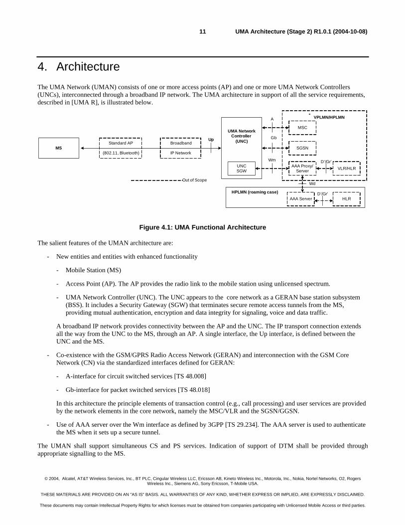
4. Architecture The UMA Network (UMAN) consists of one or more access points (AP) and one or more UMA Network Controllers (UNCs), interconnected through a broadband IP network. The UMA architecture in support of all the service requirements, described in [UMA R], is illustrated below.
MSBroadband
IP Network
MSC
SGSN
VPLMN/HPLMN
Up Gb
A
Standard AP
(802.11, Bluetooth)
UMA NetworkController
(UNC)
Out of Scope
AAA Proxy/Server
WmUNCSGW
Wd
VLR/HLRD’/Gr’
HPLMN (roaming case)HLRAAA Server
D’/Gr’
Figure 4.1: UMA Functional Architecture
The salient features of the UMAN architecture are:
- New entities and entities with enhanced functionality
- Mobile Station (MS)
- Access Point (AP). The AP provides the radio link to the mobile station using unlicensed spectrum.
- UMA Network Controller (UNC). The UNC appears to the core network as a GERAN base station subsystem (BSS). It includes a Security Gateway (SGW) that terminates secure remote access tunnels from the MS, providing mutual authentication, encryption and data integrity for signaling, voice and data traffic.
A broadband IP network provides connectivity between the AP and the UNC. The IP transport connection extends all the way from the UNC to the MS, through an AP. A single interface, the Up interface, is defined between the UNC and the MS.
- Co-existence with the GSM/GPRS Radio Access Network (GERAN) and interconnection with the GSM Core Network (CN) via the standardized interfaces defined for GERAN:
- A-interface for circuit switched services [TS 48.008]
- Gb-interface for packet switched services [TS 48.018]
In this architecture the principle elements of transaction control (e.g., call processing) and user services are provided by the network elements in the core network, namely the MSC/VLR and the SGSN/GGSN.
- Use of AAA server over the Wm interface as defined by 3GPP [TS 29.234]. The AAA server is used to authenticate the MS when it sets up a secure tunnel.
The UMAN shall support simultaneous CS and PS services. Indication of support of DTM shall be provided through appropriate signalling to the MS.
© 2004, Alcatel, AT&T Wireless Services, Inc., BT PLC, Cingular Wireless LLC, Ericsson AB, Kineto Wireless Inc., Motorola, Inc., Nokia, Nortel Networks, O2, Rogers Wireless Inc., Siemens AG, Sony Ericsson, T-Mobile USA.
THESE MATERIALS ARE PROVIDED ON AN "AS IS" BASIS. ALL WARRANTIES OF ANY KIND, WHETHER EXPRESS OR IMPLIED, ARE EXPRESSLY DISCLAIMED.
These documents may contain Intellectual Property Rights for which licenses must be obtained from companies participating with Unlicensed Mobile Access or third parties.
UMA Architecture (Stage 2) R1.0.1 (2004-10-08)12
5. Functional Entities
5.1 Mobile Station The MS shall include dual mode (GSM and unlicensed) radios and the capability to switch between them. The MS supports either Bluetooth (using the Bluetooth PAN profile) or 802.11. Appendix A provides minimum radio performance specifications while Appendix B provides recommended practices
The MS supports an IP interface to the access point. In other words, the IP connection from the UNC extends all the way to the MS.
5.2 Access Point The Access Point (AP) provides the radio link towards the mobile station using unlicensed spectrum. It connects through the broadband IP network to the UNC. The AP provides Bluetooth (PAN profile) [BTSIG3] or 802.11 access point functionality [802.11]. The AP does not provide any UMA-specific gateway functions, and any generic AP can be used to interconnect the MS to the UNC via the broadband IP network.
Appendix A provides minimum radio performance specifications while Appendix B provides recommended practices.
5.3 UNC A UNC connects to a unique MSC and SGSN via the A-interface and Gb interface respectively. This does not preclude support of A-flex and Gb-flex functionality [TS 23.236]. The UNC provides functions equivalent to that of a GERAN base station controller. It connects via an IP transport connection to an AP. The UNC interfaces to the MS using the Up interface. It maintains end-to-end communication with the MS and relays GERAN signaling to the A/Gb interface towards the Core Network. Specifically, the functions supported by the UNC include:
- Up user plane speech services: Inter-working speech bearers over Up interface to speech bearers over the A-interface, including, transcoding voice to/from the MS to PCM voice when TFO/TrFO features are not being utilized from/to the MSC.
- Up user plane data services: Inter-working data transport channels over the Up interface to packet flows over the Gb interface.
- Up Security gateway (SGW) to terminate secure remote access tunnels from the MS
- Up control functionality
- Registration for UMA service access
- Set-up of UMA bearer paths for CS and PS services. This includes participation in establishment, management, and tear down of secure signaling and user plane bearers between the MS and the UNC.
- UMA functions equivalent to GSM RR and GPRS RLC such as for paging and handovers.
- Transparent transfer of L3 messages between the MS and core network
© 2004, Alcatel, AT&T Wireless Services, Inc., BT PLC, Cingular Wireless LLC, Ericsson AB, Kineto Wireless Inc., Motorola, Inc., Nokia, Nortel Networks, O2, Rogers Wireless Inc., Siemens AG, Sony Ericsson, T-Mobile USA.
THESE MATERIALS ARE PROVIDED ON AN "AS IS" BASIS. ALL WARRANTIES OF ANY KIND, WHETHER EXPRESS OR IMPLIED, ARE EXPRESSLY DISCLAIMED.
These documents may contain Intellectual Property Rights for which licenses must be obtained from companies participating with Unlicensed Mobile Access or third parties.
UMA Architecture (Stage 2) R1.0.1 (2004-10-08)13
6. Signalling and User Plane Architecture
6.1 Up Interface This is the interface between the UNC and MS. This interface operates over an IP transport network and relays GSM/GPRS signaling between the PLMN Core Network and the MS. The following sections describe the Up interface in more detail.
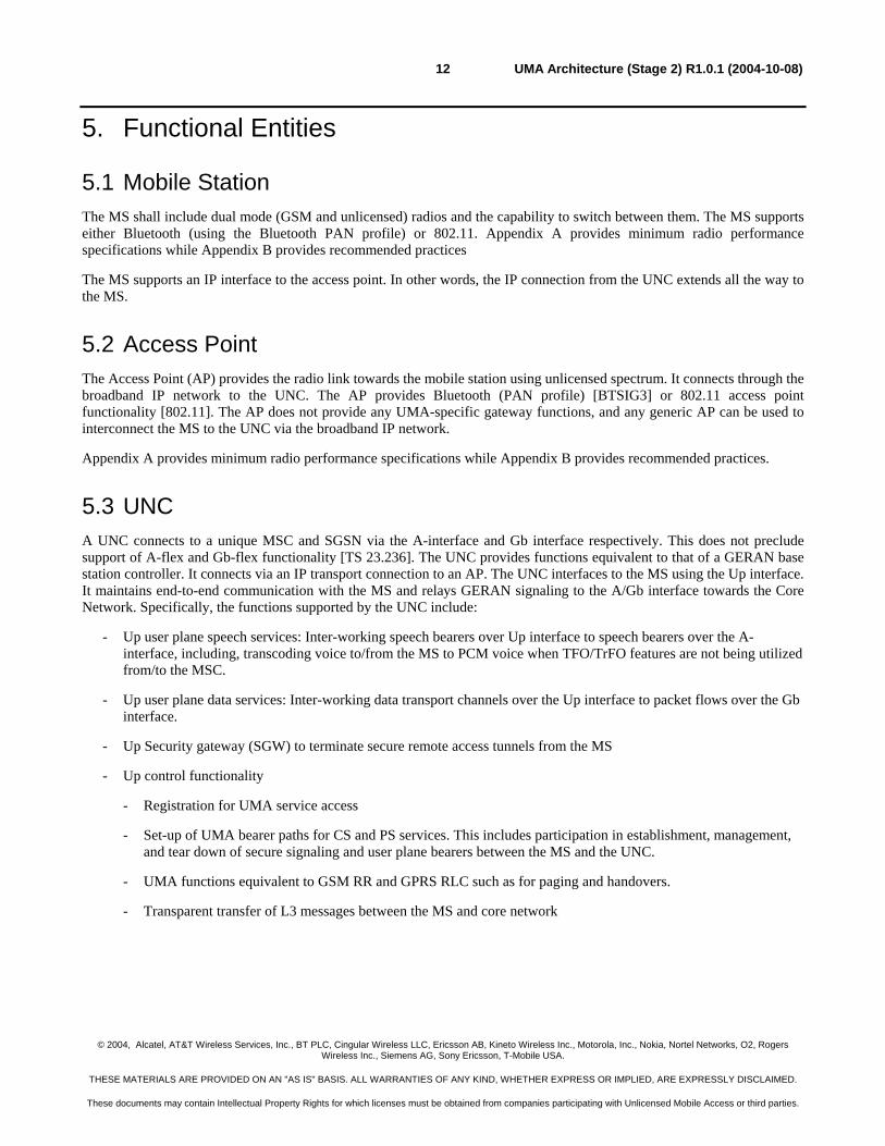
6.1.1 Up CS Domain Signaling Protocol Architecture The Up protocol architecture in support of CS Domain signaling, as well as UMA-specific signaling, is illustrated below.
Standard AP UNCMS
SCCP
MSC
SCCP
MTP3
A
UMA-RR
MM
BSSAP
MM
UnlicensedLower Layers
Transport IP
UnlicensedLower Layers
MTP2
MTP1
MTP3
MTP2
MTP1
Up Interface
Transport IP
AccessLayers
AccessLayers
Transport IP Transport IP
TCP
CC/SS/SMS CC/SS/SMS
Remote IP
TCP
UMA-RR
AccessLayers
Broadband IP Network
BSSAP
IPSec ESP
Remote IP
IPSec ESP
Figure 6.1.1.1: Up Signaling Protocol Architecture for CS Domain
The salient features of this part of the Up interface, with respect to the CS domain, are as follows:
- GSM protocols MM and above are carried transparently between the MS and MSC. This allows the MS to obtain all GSM services that it can receive through a GSM BSS, through the UMAN.
- GSM-RR protocol is replaced with a UMA-RR protocol. The unlicensed radio link presents different characteristics from that of the licensed GSM radio link, so the UMA-RR protocol is customized to take advantage of these characteristics. As in a GSM BSS, the UNC, acting like a BSC, terminates the UMA-RR protocol and inter-works it to the A-interface using BSSAP messaging.
The mapping of the IP layer over unlicensed L1/L2 is illustrated below for Bluetooth and for 802.11.
BluetoothBaseband
L2CAP
BNEP
BluetoothBaseband
L2CAP
BNEP
MS Standard AP
BluetoothLower Layers
802.11 PHY
802.11 MAC
802.11 PHY
802.11 MAC
MS Standard AP
802.11 LowerLayers
Figure 6.1.1.2: Up interface L1/L2 options
© 2004, Alcatel, AT&T Wireless Services, Inc., BT PLC, Cingular Wireless LLC, Ericsson AB, Kineto Wireless Inc., Motorola, Inc., Nokia, Nortel Networks, O2, Rogers Wireless Inc., Siemens AG, Sony Ericsson, T-Mobile USA.
THESE MATERIALS ARE PROVIDED ON AN "AS IS" BASIS. ALL WARRANTIES OF ANY KIND, WHETHER EXPRESS OR IMPLIED, ARE EXPRESSLY DISCLAIMED.
These documents may contain Intellectual Property Rights for which licenses must be obtained from companies participating with Unlicensed Mobile Access or third parties.
UMA Architecture (Stage 2) R1.0.1 (2004-10-08)14
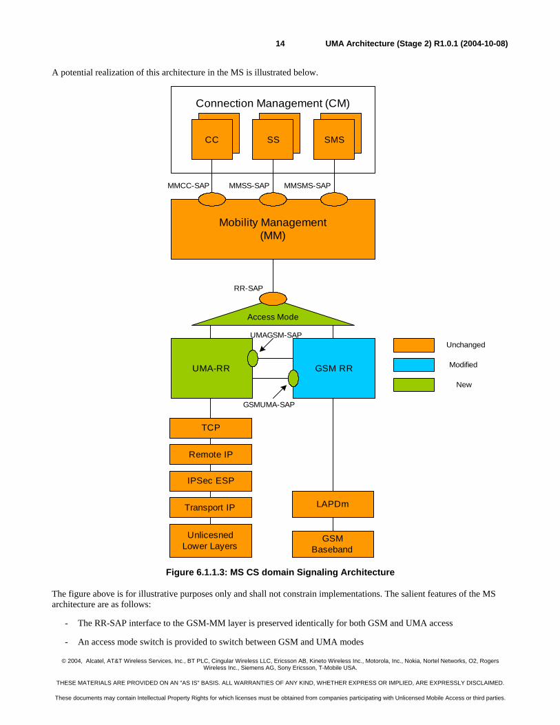
A potential realization of this architecture in the MS is illustrated below.
Connection Management (CM)
Mobility Management(MM)
CC SS SMS
MMCC-SAP MMSS-SAP MMSMS-SAP
Access Mode
RR-SAP
UMA-RR GSM RR
Unchanged
Modified
New
LAPDm
UMAGSM-SAP
GSMUMA-SAP
GSMBaseband
TCP
Remote IP
IPSec ESP
Transport IP
UnlicesnedLower Layers
Figure 6.1.1.3: MS CS domain Signaling Architecture
The figure above is for illustrative purposes only and shall not constrain implementations. The salient features of the MS architecture are as follows:
- The RR-SAP interface to the GSM-MM layer is preserved identically for both GSM and UMA access
- An access mode switch is provided to switch between GSM and UMA modes
© 2004, Alcatel, AT&T Wireless Services, Inc., BT PLC, Cingular Wireless LLC, Ericsson AB, Kineto Wireless Inc., Motorola, Inc., Nokia, Nortel Networks, O2, Rogers Wireless Inc., Siemens AG, Sony Ericsson, T-Mobile USA.
THESE MATERIALS ARE PROVIDED ON AN "AS IS" BASIS. ALL WARRANTIES OF ANY KIND, WHETHER EXPRESS OR IMPLIED, ARE EXPRESSLY DISCLAIMED.
These documents may contain Intellectual Property Rights for which licenses must be obtained from companies participating with Unlicensed Mobile Access or third parties.
UMA Architecture (Stage 2) R1.0.1 (2004-10-08)15
- UMA-RR peers with GSM-RR.
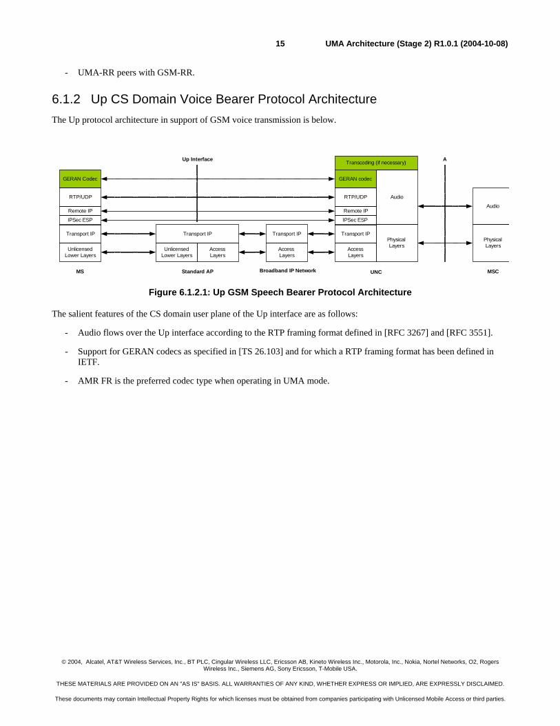
6.1.2 Up CS Domain Voice Bearer Protocol Architecture The Up protocol architecture in support of GSM voice transmission is below.
Standard AP UNCMS
Audio
PhysicalLayers
MSC
A
Audio
PhysicalLayers
GERAN Codec
UnlicensedLower Layers
Transcoding (if necessary)
GERAN codec
AccessLayers
Transport IP Transport IPTransport IP
UnlicensedLower Layers
Transport IP
AccessLayers
RTP/UDP RTP/UDP
Up Interface
Broadband IP Network
AccessLayers
Remote IP
IPSec ESP
Remote IP
IPSec ESP
Figure 6.1.2.1: Up GSM Speech Bearer Protocol Architecture
The salient features of the CS domain user plane of the Up interface are as follows:
- Audio flows over the Up interface according to the RTP framing format defined in [RFC 3267] and [RFC 3551].
- Support for GERAN codecs as specified in [TS 26.103] and for which a RTP framing format has been defined in IETF.
- AMR FR is the preferred codec type when operating in UMA mode.
© 2004, Alcatel, AT&T Wireless Services, Inc., BT PLC, Cingular Wireless LLC, Ericsson AB, Kineto Wireless Inc., Motorola, Inc., Nokia, Nortel Networks, O2, Rogers Wireless Inc., Siemens AG, Sony Ericsson, T-Mobile USA.
THESE MATERIALS ARE PROVIDED ON AN "AS IS" BASIS. ALL WARRANTIES OF ANY KIND, WHETHER EXPRESS OR IMPLIED, ARE EXPRESSLY DISCLAIMED.
These documents may contain Intellectual Property Rights for which licenses must be obtained from companies participating with Unlicensed Mobile Access or third parties.
UMA Architecture (Stage 2) R1.0.1 (2004-10-08)16
ADC/DACADC/DAC
Access Mode
GSMCodecs Unchanged
Modified
New
GSMBaseband
GSM Codec
RTP/UDP
Remote IP
IPSec ESP
Transport IP
UnlicensedLower Layers
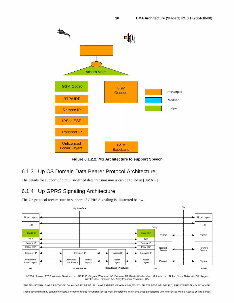
Figure 6.1.2.2: MS Architecture to support Speech
6.1.3 Up CS Domain Data Bearer Protocol Architecture The details for support of circuit switched data transmission is can be found in [UMA P].
6.1.4 Up GPRS Signaling Architecture The Up protocol architecture in support of GPRS Signaling is illustrated below.
UNCMS
LLC
Upper Layers
SGSN
Upper Layers
BSSGP
NetworkService
Physical
NetworkService
Physical
BSSGP
Transport IP
UnlicensedLower Layers
UMA-RLC UMA-RLC
GbUp Interface
AccessLayers
Transport IP Transport IP
TCPTCP
Standard AP
UnlicensedLower Layers
Transport IP
AccessLayers
AccessLayers
Broadband IP Network
LLC
Remote IP
IPSec ESP
Remote IP
IPSec ESP
Relay
© 2004, Alcatel, AT&T Wireless Services, Inc., BT PLC, Cingular Wireless LLC, Ericsson AB, Kineto Wireless Inc., Motorola, Inc., Nokia, Nortel Networks, O2, Rogers Wireless Inc., Siemens AG, Sony Ericsson, T-Mobile USA.
THESE MATERIALS ARE PROVIDED ON AN "AS IS" BASIS. ALL WARRANTIES OF ANY KIND, WHETHER EXPRESS OR IMPLIED, ARE EXPRESSLY DISCLAIMED.
These documents may contain Intellectual Property Rights for which licenses must be obtained from companies participating with Unlicensed Mobile Access or third parties.
UMA Architecture (Stage 2) R1.0.1 (2004-10-08)17
Figure 6.1.4.1: Up GPRS Signaling Architecture
The salient features of this part of the Up interface are as follows:
- GPRS LLC PDUs for signaling and higher layer protocols are carried transparently between the MS and SGSN. This allows the MS to obtain all GPRS services in the same way as if it were connected to a GERAN BSS.
- GPRS-RLC protocol is replaced with an equivalent UMA-RLC protocol. Given the transport characteristics over Up interface the GPRS TBF abstraction is not applicable and reliability is ensured by TCP. Therefore the UMA-RLC is significantly lighter than GPRS-RLC. As in a GERAN BSS, the UNC, acting like a BSC, terminates the UMA-RLC protocol and inter-works it to the Gb-interface using BSSGP.
A potential realization of this architecture in the MS is illustrated below.
© 2004, Alcatel, AT&T Wireless Services, Inc., BT PLC, Cingular Wireless LLC, Ericsson AB, Kineto Wireless Inc., Motorola, Inc., Nokia, Nortel Networks, O2, Rogers Wireless Inc., Siemens AG, Sony Ericsson, T-Mobile USA.
THESE MATERIALS ARE PROVIDED ON AN "AS IS" BASIS. ALL WARRANTIES OF ANY KIND, WHETHER EXPRESS OR IMPLIED, ARE EXPRESSLY DISCLAIMED.
These documents may contain Intellectual Property Rights for which licenses must be obtained from companies participating with Unlicensed Mobile Access or third parties.
UMA Architecture (Stage 2) R1.0.1 (2004-10-08)18
Logical Link Control(LLC)
GMMSNDCP
SMS
UMA-RLC GPRS RLC
Access Mode
GRR-SAPGMMRR-SAP
Unchanged
Modified
New
UMAGPRS-SAP
GPRSUMA-SAP
IP
App
MAC
GSMBaseband
TCP, UDP
Remote IP
IPSec ESP
Transport IP
UnlicensedLower Layers
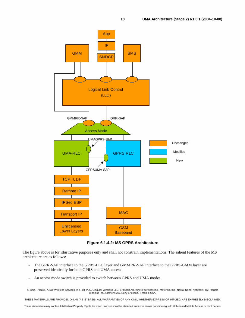
Figure 6.1.4.2: MS GPRS Architecture
The figure above is for illustrative purposes only and shall not constrain implementations. The salient features of the MS architecture are as follows:
- The GRR-SAP interface to the GPRS-LLC layer and GMMRR-SAP interface to the GPRS-GMM layer are preserved identically for both GPRS and UMA access
- An access mode switch is provided to switch between GPRS and UMA modes
© 2004, Alcatel, AT&T Wireless Services, Inc., BT PLC, Cingular Wireless LLC, Ericsson AB, Kineto Wireless Inc., Motorola, Inc., Nokia, Nortel Networks, O2, Rogers Wireless Inc., Siemens AG, Sony Ericsson, T-Mobile USA.
THESE MATERIALS ARE PROVIDED ON AN "AS IS" BASIS. ALL WARRANTIES OF ANY KIND, WHETHER EXPRESS OR IMPLIED, ARE EXPRESSLY DISCLAIMED.
These documents may contain Intellectual Property Rights for which licenses must be obtained from companies participating with Unlicensed Mobile Access or third parties.
UMA Architecture (Stage 2) R1.0.1 (2004-10-08)19
- UMA-RLC peers with GPRS-RLC to provide coordination for access mode switching and handovers
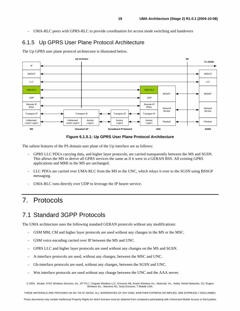
6.1.5 Up GPRS User Plane Protocol Architecture The Up GPRS user plane protocol architecture is illustrated below.
UNCMS
LLC
SNDCP
IP
SGSN
LLC
To GGSN
BSSGP
NetworkService
Physical
NetworkService
Physical
BSSGP
Transport IP
UnlicensedLower Layers
UMA-RLC
GbUp Interface
AccessLayers
Transport IP Transport IP
Remote IPIPSec
UMA-RLC
Remote IPIPsec
Standard AP
UnlicensedLower Layers
Transport IP
AccessLayers
SNDCP
AccessLayers
Broadband IP Network
UDP UDP
Figure 6.1.5.1: Up GPRS User Plane Protocol Architecture
The salient features of the PS domain user plane of the Up interface are as follows:
- GPRS LLC PDUs carrying data, and higher layer protocols, are carried transparently between the MS and SGSN. This allows the MS to derive all GPRS services the same as if it were in a GERAN BSS. All existing GPRS applications and MMI in the MS are unchanged.
- LLC PDUs are carried over UMA-RLC from the MS to the UNC, which relays it over to the SGSN using BSSGP messaging.
- UMA-RLC runs directly over UDP to leverage the IP bearer service.
7. Protocols
7.1 Standard 3GPP Protocols The UMA architecture uses the following standard GERAN protocols without any modifications:
- GSM MM, CM and higher layer protocols are used without any changes in the MS or the MSC.
- GSM voice encoding carried over IP between the MS and UNC.
- GPRS LLC and higher layer protocols are used without any changes on the MS and SGSN.
- A-interface protocols are used, without any changes, between the MSC and UNC.
- Gb-interface protocols are used, without any changes, between the SGSN and UNC.
- Wm interface protocols are used without any change between the UNC and the AAA server.
© 2004, Alcatel, AT&T Wireless Services, Inc., BT PLC, Cingular Wireless LLC, Ericsson AB, Kineto Wireless Inc., Motorola, Inc., Nokia, Nortel Networks, O2, Rogers Wireless Inc., Siemens AG, Sony Ericsson, T-Mobile USA.
THESE MATERIALS ARE PROVIDED ON AN "AS IS" BASIS. ALL WARRANTIES OF ANY KIND, WHETHER EXPRESS OR IMPLIED, ARE EXPRESSLY DISCLAIMED.
These documents may contain Intellectual Property Rights for which licenses must be obtained from companies participating with Unlicensed Mobile Access or third parties.
UMA Architecture (Stage 2) R1.0.1 (2004-10-08)20
Further, all GSM and GPRS protocols on the MS are unaffected when they are operating over the GERAN BSS.
7.2 Standard Unlicensed Radio Access Protocols The UMA architecture uses the following WLAN protocols without any modifications:
- 802.11 protocols for PHY and MAC, including functions for association, authentication, encryption, data transfer and traffic prioritization [802.11].
- Bluetooth protocols for PHY, Baseband, LMP, L2CAP and SDP, including functions for discovery, paging, pairing (authentication), encryption, ACL and data and voice traffic transfer. Additionally, BNEP is used to provide Ethernet emulation over Bluetooth ACL links as per the PAN profile. [BTSIG3]
Minimum radio performance requirements and Recommended practices for use of IEEE 802.11 and Bluetooth are presented in Appendix A and Appendix B respectively.
7.3 Standard IP-based Protocols The UMA architecture uses the following standard IP-based protocols without any modifications:
- IP over standard lower layers [RFC 791]
- TCP to provide a tunnel for GSM/GPRS signaling and SMS [RFC 793]
- IPsec ESP to provide a secure tunnel for GERAN user and control plane traffic [RFC 2406]
- IKEv2 [IKEv2] and EAP-SIM [EAP SIM] for authentication and establishing and maintaining a security association between MS and UNC
- UDP [RFC 768]for IPsec NAT traversal [IPSec NAT]
- UDP for GPRS data transfer
- RTP/UDP for transfer of GSM vocoder frames over IP transport [RFC 3550]
7.4 UMA Specific Protocols
7.4.1 UMA-RR UMA Radio Resource (UMA-RR) protocol provides a radio resource management layer, which is the peer of GSM-RR, in the MS. It is designed to take advantage of the characteristics of the unlicensed radio link as they are quite different from that of the GERAN radio link. Specifically, it provides the following functions:
- Registration with UNC
- Setup of bearer path for CS traffic between the MS and UNC
- Handover support between GERAN and UMA- Functions such as GPRS suspension, paging, ciphering configuration, classmark change, application level keep-alive etc. - Support for identification of the AP being used for UMA access.
7.4.2 UMA-RLC UMA Radio Link Control (UMA-RLC) protocol provides the following services:
© 2004, Alcatel, AT&T Wireless Services, Inc., BT PLC, Cingular Wireless LLC, Ericsson AB, Kineto Wireless Inc., Motorola, Inc., Nokia, Nortel Networks, O2, Rogers Wireless Inc., Siemens AG, Sony Ericsson, T-Mobile USA.
THESE MATERIALS ARE PROVIDED ON AN "AS IS" BASIS. ALL WARRANTIES OF ANY KIND, WHETHER EXPRESS OR IMPLIED, ARE EXPRESSLY DISCLAIMED.
These documents may contain Intellectual Property Rights for which licenses must be obtained from companies participating with Unlicensed Mobile Access or third parties.
UMA Architecture (Stage 2) R1.0.1 (2004-10-08)21
- delivery of GPRS signaling, SMS messages over the secure tunnel.
- paging, flow control, GPRS transport channel management
- transfer of GPRS user plane data.
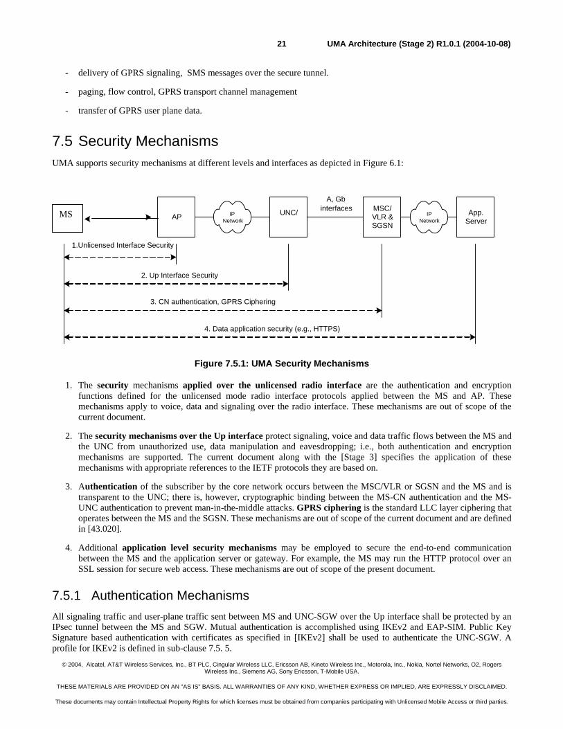
7.5 Security Mechanisms UMA supports security mechanisms at different levels and interfaces as depicted in Figure 6.1:
Figure 7.5.1: UMA Security Mechanisms
1. The security mechanisms applied over the unlicensed radio interface are the authentication and encryption functions defined for the unlicensed mode radio interface protocols applied between the MS and AP. These mechanisms apply to voice, data and signaling over the radio interface. These mechanisms are out of scope of the current document.
2. The security mechanisms over the Up interface protect signaling, voice and data traffic flows between the MS and the UNC from unauthorized use, data manipulation and eavesdropping; i.e., both authentication and encryption mechanisms are supported. The current document along with the [Stage 3] specifies the application of these mechanisms with appropriate references to the IETF protocols they are based on.
3. Authentication of the subscriber by the core network occurs between the MSC/VLR or SGSN and the MS and is transparent to the UNC; there is, however, cryptographic binding between the MS-CN authentication and the MS-UNC authentication to prevent man-in-the-middle attacks. GPRS ciphering is the standard LLC layer ciphering that operates between the MS and the SGSN. These mechanisms are out of scope of the current document and are defined in [43.020].
4. Additional application level security mechanisms may be employed to secure the end-to-end communication between the MS and the application server or gateway. For example, the MS may run the HTTP protocol over an SSL session for secure web access. These mechanisms are out of scope of the present document.
7.5.1 Authentication Mechanisms All signaling traffic and user-plane traffic sent between MS and UNC-SGW over the Up interface shall be protected by an IPsec tunnel between the MS and SGW. Mutual authentication is accomplished using IKEv2 and EAP-SIM. Public Key Signature based authentication with certificates as specified in [IKEv2] shall be used to authenticate the UNC-SGW. A profile for IKEv2 is defined in sub-clause 7.5. 5.
UNC/AP IPNetwork
MSC/VLR &SGSN
A, Gbinterfaces
2. Up Interface Security
App.Server
1.Unlicensed Interface Security
3. CN authentication, GPRS Ciphering
4. Data application security (e.g., HTTPS)
IPNetwork
MS
© 2004, Alcatel, AT&T Wireless Services, Inc., BT PLC, Cingular Wireless LLC, Ericsson AB, Kineto Wireless Inc., Motorola, Inc., Nokia, Nortel Networks, O2, Rogers Wireless Inc., Siemens AG, Sony Ericsson, T-Mobile USA.
THESE MATERIALS ARE PROVIDED ON AN "AS IS" BASIS. ALL WARRANTIES OF ANY KIND, WHETHER EXPRESS OR IMPLIED, ARE EXPRESSLY DISCLAIMED.
These documents may contain Intellectual Property Rights for which licenses must be obtained from companies participating with Unlicensed Mobile Access or third parties.
UMA Architecture (Stage 2) R1.0.1 (2004-10-08)22
7.5.2 Confidentiality Mechanisms All signaling traffic and user-plane traffic, sent between MS and UNC-SGW over the Up interface shall be protected by IPsec ESP [RFC 2406]. A profile for IPsec ESP is defined in sub-clause 7.5.6.
7.5.3 Integrity Mechanisms All signaling and user-plane traffic sent between MS and UNC-SGW over the Up interface shall be protected by IPsec ESP. A profile for IPsec ESP is defined in sub-clause 7.5.6.
7.5.4 User Credentials All long-term security credentials used for subscriber and network authentication are stored on the SIM.
7.5.5 Profile of IKEv2 The IKEv2 specification [IKEv2] contains a number of options for the cryptographic algorithms. In order to limit the implementation requirements, IKEv2 is profiled for UMA. The profile is aligned with 3GPP WLAN Interworking, Scenario 3 [TS 33.234].
Access to UMAN services follows a VPN-like approach. In [IPSec UI] can be found a set of recommendations of IKEv2 profiles, suitable for VPN-like solutions. On the other hand, [IKEv2 Crypto] sets rules and recommendations for individual algorithms support. Following recommendation from both papers, the below two profiles shall be supported by the MS and UNC-SGW – UNC-SGW shall support both profiles, while the MS shall support at least one of the two profiles:
- First cryptographic suite:
- Confidentiality: 3DES in CBC mode (also known as ENCR_3DES) per RFC 2451;
- Pseudo-random function: HMAC-SHA1 (also known as PRF_HMAC_SHA1) per RFC 2104;
- Integrity: HMAC-SHA1-96 (also known as AUTH_HMAC_SHA1_96) per RFC 2404;
- Diffie-Hellman group 2 (1024-bit MODP) per RFC 2409
- Second cryptographic suite:
- Confidentiality: AES with fixed key length in CBC mode. The key length is set to 128 bits (also known as ENCR_AES_CBC) per RFC 3602;
- Pseudo-random function: AES-XCBC-PRF-128 (also known as PRF_AES_CBC) per RFC 3664;
- Integrity: AES-XCBC-MAC-96 (also known as AUTH_AES_PRF_128) per RFC 3566.
- Diffie-Hellman group 2 (1024-bit MODP) per RFC 2409
For NAT traversal, the NAT support of IKEv2 shall be supported as specified in section 2.23 of [IPSec NAT].
For authentication:
- EAP-SIM [EAP-SIM] shall be used, and it provides mutual authentication between MS and AAA server
- Public key signature based authentication for UNC-SGW as follows:
- X.509 v3 certificate encoded in DER format, per RFC 3280
- Certificate encoding shall be 4 (X.509 certificate – Signature).
© 2004, Alcatel, AT&T Wireless Services, Inc., BT PLC, Cingular Wireless LLC, Ericsson AB, Kineto Wireless Inc., Motorola, Inc., Nokia, Nortel Networks, O2, Rogers Wireless Inc., Siemens AG, Sony Ericsson, T-Mobile USA.
THESE MATERIALS ARE PROVIDED ON AN "AS IS" BASIS. ALL WARRANTIES OF ANY KIND, WHETHER EXPRESS OR IMPLIED, ARE EXPRESSLY DISCLAIMED.
These documents may contain Intellectual Property Rights for which licenses must be obtained from companies participating with Unlicensed Mobile Access or third parties.
UMA Architecture (Stage 2) R1.0.1 (2004-10-08)23
- Version: shall be 2 ("v3").
- Certificate serial number (SerialNumber): Assigned by the issuing CA. It shall not be longer than 20 bytes (159 bits since top-most bit shall be set to 0). MS shall be able to handle serial number values up to 20 bytes long. This is used by the MS to check certificate revocation status.
- Signature algorithm (Signature): Algorithm used by the issuing CA to sign the certificate. It shall be sha1WithRSAEncryption. The keys used for signing shall not be longer than 2048 bits. This is used by the MS to verify the signature value.
- Signature Value: RSA digital signature computed upon DER-encoded certificate fields, as specified in RFC 3280. This is used by the MS to validate the certificate, using the issuing CA’s public key.
- Issuer name (Issuer): Distinguished name of issuing CA. MS shall recognize all required distinguished name attributes listed in Section 4.1.2.4 of RFC3280. MS shall be able to process certificates even if naming attributes are unknown. This field shall not be left empty. This is used by the MS to match against one of the CAs it supports, or one of the CAs in the certificate chain.
- Validity: Date on which certificate validity period begins (notBefore) and ends (notAfter). It shall be encoded as UTCTime (YYMMDDHHMMSSZ) where YY >= 50 is interpreted as 19YY, and YY < 50 is interpreted as 20YY. This is used by the MS to check the validity of the certificate.
- Subject name (Subject): Distinguished name of the UNC-SGW, or CA (in a certificate chain). This field may be empty. This field shall be present if this is a CA certificate; it may be empty in end-entity certificates. The MS shall not assume that the CN attribute is present, or use it instead of or in addition to SubjectAltName.
- Subject public key (SubjectPublicKeyInfo): The algorithm shall be RsaEncryption, and the RSA public key shall not be longer than 2048 bits. This is used by the MS to validate the AUTH payload (if this is UNC-SGW certificate) or to validate the certificate chain (if this is a CA certificate).
- The issuerUniqueID or subjectUniqueID fields shall not be present.
- SubjectAltName extension: It shall be present if this is a UNC-SGW certificates, and shall contain at least one DNSname or IPAddress component depending on the type of IDr payload). This is used by the MS to validate the IDr payload.
- BasicConstraints extension: It shall be present if this is a CA certificates with "CA" flag asserted. The pathLenConstraint MAY be present, and shall be supported by the MS.
- KeyUsage extension: It shall be present in all certificates. The keyCertSign shall be set on CA certificates, and digitalSignature bit shall be set for end entity certificates.
- ExtKeyUsage, cRLDistributionPoints, certificatePolicies: These may be present. If present, they shall not be marked as critical.
- Other extensions should not be used; if they are, they shall not be marked as critical.
- The total length of a certificate shall not exceed 2000 bytes.
7.5.6 Profile of IPsec ESP The IPsec specification contains a number of options for the cryptographic algorithms for IPsec ESP. In order to limit the implementation requirements, a specified profile of IPsec ESP is applied. The profile is aligned with 3GPP WLAN Interworking, Scenario 3 [TS 33.234].
© 2004, Alcatel, AT&T Wireless Services, Inc., BT PLC, Cingular Wireless LLC, Ericsson AB, Kineto Wireless Inc., Motorola, Inc., Nokia, Nortel Networks, O2, Rogers Wireless Inc., Siemens AG, Sony Ericsson, T-Mobile USA.
THESE MATERIALS ARE PROVIDED ON AN "AS IS" BASIS. ALL WARRANTIES OF ANY KIND, WHETHER EXPRESS OR IMPLIED, ARE EXPRESSLY DISCLAIMED.
These documents may contain Intellectual Property Rights for which licenses must be obtained from companies participating with Unlicensed Mobile Access or third parties.
UMA Architecture (Stage 2) R1.0.1 (2004-10-08)24
Rules and recommendations in [IPSec UI] and [IKEv2 Crypto] have been followed, as in case of IKEv2. The below two profiles shall be supported by the MS and UNC-SGW – UNC-SGW shall support both profiles, while the MS shall support at least one of the two profiles:
First cryptographic suite:
- Confidentiality: 3DES in CBC mode (also known as ENCR_3DES) per RFC 2451;
- Integrity: HMAC-SHA1-96 (also known as PRF_HMAC_SHA1). The key length is 160 bits, according to RFC 2104 and RFC 2404;
- Tunnel mode must be used.
Second cryptographic suite:
- Confidentiality: AES with 128-bit keys in CBC mode. The key length is set to 128 bits (also known as ENCR_AES_CBC) per RFC 3602;
- Integrity: AES-XCBC-MAC-96 (also known as AUTH_AES_PRF_128) per RFC 3566;
- Tunnel mode must be used.
It shall be possible to turn off confidentiality in the tunnel (for example high trust between the UMAN operator and the access network provider). This means that transform IDs for encryption ENCR_NULL shall be allowed to negotiate, as specified in [IKEv2].
For NAT traversal, the UDP encapsulation for ESP tunnel mode specified [IPSec NAT] shall be supported.
8. Identifiers in UMA
8.1 Identifiers for MSs and APs The following are the key MS and AP addressing parameters.
1. The IMSI associated with the SIM in the terminal.
This identifier is provided by the MS to the UNC when it registers to a UNC. The UNC maintains a record for each registered MS. For example, IMSI is used by the UNC to find the appropriate MS record when the UNC receives a BSSMAP PAGING message.
2. Public IP Address of the MS
The Public IP address of MS is the source IP present in the outermost IP header of packets received from the MS by the UNC-SGW. If available, this identifier may be used by the UNC to support locations services and fraud detection. It may also be used by service providers to signal Managed IP networks IP flows that require QoS treatment.
3. The “Access Point (AP) ID”.
The AP-ID is the MAC address of the unlicensed mode access point through which the MS is accessing UMA service. This identifier is provided by the MS (obtained via broadcast from the AP) to the UNC via the Up interface, when it requests UMA service. The AP-ID may be used by the UNC to support location services. The AP-ID may also be used by the service provider to restrict UMA service access via only authorized APs.
© 2004, Alcatel, AT&T Wireless Services, Inc., BT PLC, Cingular Wireless LLC, Ericsson AB, Kineto Wireless Inc., Motorola, Inc., Nokia, Nortel Networks, O2, Rogers Wireless Inc., Siemens AG, Sony Ericsson, T-Mobile USA.
THESE MATERIALS ARE PROVIDED ON AN "AS IS" BASIS. ALL WARRANTIES OF ANY KIND, WHETHER EXPRESS OR IMPLIED, ARE EXPRESSLY DISCLAIMED.
These documents may contain Intellectual Property Rights for which licenses must be obtained from companies participating with Unlicensed Mobile Access or third parties.
UMA Architecture (Stage 2) R1.0.1 (2004-10-08)25
8.2 Cell identifiers for UMA In UMAN, as in GERAN, a cell is identified by a Cell Global Identity (CGI) which is the concatenation of a Location Area Identity (LAI) and Cell Identity (CI).
NOTE: The location area (or routing area) assigned to the UMAN cells may be distinct from, or the same as, the location area (or routing area) of the overlapping GERAN cells.
8.2.1 UMAN Cell Id for Location Services & Billing Cell identities (CGI) are often used to route the call to location dependent services such as emergency calling, operators, announcements and freephone numbers. Cell identities can also used by the core network to identify the location of the call for billing purposes. To meet these requirements, the UNC provides a CGI to the core network indicating the UMAN cell that the call originated from.
8.2.1.1 Assigning UMAN Cell Id based on GSM location
In the UMAN architecture, the MS has a direct, IP-based connection to the UNC, so the notion of a “cell” is defined by some logical grouping of MSs being served by a UNC. Since the UMAN coverage area overlaps the GERAN coverage area, the simplest grouping of MSs is based on the overlapping GSM cell that the MS is located in. This can be done at various location resolutions, such as:
- a UMAN cell for each GSM cell, or
- a UMAN cell for each GSM location area, or
- a UMAN cell for some other mapping of GSM cells into UMAN cells
The mapping of GSM cells into UMAN cells is defined in the UNC. A single UNC could represent one or more cells (CGI) in one or more location areas (LAI) for location services.
This mechanism allows the operator to leverage any existing location infrastructure for GSM cell sites, and provides MS location to the resolution of existing GSM cell sites.
8.2.1.2 Assigning UMAN Cell Id based on other information
The UNC can use other information provided by the MS, such as the identity or location of the AP, or GPS co-ordinates, to identify the geographic location of the MS, and map it to a corresponding UMAN cell id, based on operator configuration.
8.2.1.3 Determining UMAN Cell Id during UMAN Registration
During UMAN registration (see section 9.2.1 for more details), if the MS is in GERAN coverage, it indicates to the UNC the cell id of the overlapping GERAN cell. The UNC then maps this information to a corresponding UMAN cell id and stores it in the registration context of that MS. This UMAN cell id is also provided to the MS in the system information during UMAN registration, so the MS can do a location update with the core network, if required.
During UMAN registration, if the MS is not in GSM coverage, then the cell id of the overlapping GERAN cell (and corresponding GAN cell id) may not be determined reliably. In this case, the UNC allows the operator to apply a service policy – either deny UMAN service, or allow it with an explicit indication to the MS that its location is unknown. In the latter case, the UNC will assign a default UMAN cell id for this MS registration context, and also indicate that to the MS in the system information.
When the MS places a call, including an emergency call over UMAN (see section 9.8 for more details), the UNC passes to the core network the UMAN cell id (CGI) value stored in the MS registration context. The core network must be configured with the new UMAN cell id values; however, the GERAN cell id and corresponding UMAN cell id can share the same location information e.g. cell site address, location co-ordinates, serving Emergency Centre, etc. If the UMAN cell id
© 2004, Alcatel, AT&T Wireless Services, Inc., BT PLC, Cingular Wireless LLC, Ericsson AB, Kineto Wireless Inc., Motorola, Inc., Nokia, Nortel Networks, O2, Rogers Wireless Inc., Siemens AG, Sony Ericsson, T-Mobile USA.
THESE MATERIALS ARE PROVIDED ON AN "AS IS" BASIS. ALL WARRANTIES OF ANY KIND, WHETHER EXPRESS OR IMPLIED, ARE EXPRESSLY DISCLAIMED.
These documents may contain Intellectual Property Rights for which licenses must be obtained from companies participating with Unlicensed Mobile Access or third parties.
UMA Architecture (Stage 2) R1.0.1 (2004-10-08)26
corresponds to the “no GSM coverage” case, the core network will need a special configuration for that cell id (e.g. to route an emergency call to a default Emergency Centre, no automatic location identification, etc.).
8.2.1.4 UMAN Cell Id for Roaming Scenario
If, during UMAN registration, an MS reports a GERAN cell id to the UNC that indicates the MS is in a location that is not served by this UNC (e.g. because the MS is roaming in a foreign country or another PLMN), the UNC can map the MS to one of several distinct UMAN cell ids (configured in the UNC according to operator policy).
This UMAN cell id is sent to the MS in system information during UMAN registration (and is subsequently used by MS for core network registration). Therefore, it can be used to implement roaming restrictions, using existing mechanisms (e.g. in the SIM or in the HLR).
8.2.2 UMAN Cell Id for handover-to-UMAN The UMA cell id used for location and billing can be independent from the UMA cell id used for handover.
A single UNC represents a single cell, and referred to as UMA cell, for the purpose of handover from GERAN to UMAN. This “handover-UNC-CGI” is not visible to the UNC or the MS, and is only used in the GERAN and CN for identifying a target cell for handover from GERAN to UMAN.
The “handover-UNC-CGI” assigned to the UNC is configured as the target handover cell in all neighbouring GERAN cells (in the ARFCN/BSIC-to-CGI mapping table). Neighbouring GERAN cells are those whose service area “overlaps” the UNC service area, for the purpose of handover.
For example, neighbour cells are:
- All GERAN cells attached to the same MSC as the UNC
- All GERAN cells attached to a different MSC but that can handover to the MSC to which the UNC is attached.
When the MS reports measurements to the GERAN BSS on the UMA cell identified by its ARFCN/BSIC, then the GERAN BSS maps the ARFCN/BSIC to the “handover-UNC-CGI” through its mapping table, and is thus able to identify the target cell (UNC) for handover-to-UMAN.
8.2.3 UMAN ARFCN/BSIC for handover-to-UMAN The GERAN-to-UMAN handover method makes use of an RF channel number (ARFCN) and base station identity code (BSIC) parameters to identify the UMA target cell. All UNCs in a given operator domain can share the same ARFCN/BSIC values, if there is a single UNC neighbor per GSM cell. This ARFCN/BSIC is indicated to the MS by the UNC during UMAN registration
Selection of ARFCN should follo w the following guidelines:
1. The ARFCN should not be allocated from the operator’s existing BCCH pool so that a scarce BCCH is not used.
2. The ARFCN is desired to be the same unique number across the whole operator network so that the BSS configuration effort can be minimized.
The following are available options for the selection of the ARFCN:
1. Ideally, the UMAN is assigned an ARFCN value which is not in the frequency bands currently used by the operator.
2. Typically, different PLMNs in the same country have disjoint frequency allocations. For each PLMN, some of the frequencies are reserved for BCCH beacon; BCCH will be transmitted with constant max power on time slot 0. Other frequencies are dedicated as traffic channels. The UMAN ARFCN could use any non-BCCH frequency from
© 2004, Alcatel, AT&T Wireless Services, Inc., BT PLC, Cingular Wireless LLC, Ericsson AB, Kineto Wireless Inc., Motorola, Inc., Nokia, Nortel Networks, O2, Rogers Wireless Inc., Siemens AG, Sony Ericsson, T-Mobile USA.
THESE MATERIALS ARE PROVIDED ON AN "AS IS" BASIS. ALL WARRANTIES OF ANY KIND, WHETHER EXPRESS OR IMPLIED, ARE EXPRESSLY DISCLAIMED.
These documents may contain Intellectual Property Rights for which licenses must be obtained from companies participating with Unlicensed Mobile Access or third parties.
UMA Architecture (Stage 2) R1.0.1 (2004-10-08)27
the carrier’s existing frequency pool. Standard GSM MSs will be able to tune onto this channel but will not be able to find the FCCH burst.
3. Alternatively, in a PCS-only (1900 MHz) network, ARFCN can be any value falling within the GSM (900 MHz) or DCS (1800 MHz) band. Standard GSM handsets operating in PCS-only mode will ignore this ARFCN. Tri-band handsets supporting automatic band change will not be able to find a BCCH on the associated frequency.
9. High-Level Procedures
9.1 Mode and PLMN Selection
9.1.1 Mode Selection
At any given time, the MS is in one of two operating modes:
- GSM mode:
- GSM RR is the serving RR entity
- UMA mode:
- UMA RR is the serving RR entity.
On power up, the MS starts in GSM mode and executes the normal GSM power-up sequence [3GPP 23.122]. After that, it might switch into UMA mode based on mode selection preference determined by user preferences and service provider configuration [UMA R]. Emergency calling procedures have certain exceptions that are described in sub-clause 9.17.
- GERAN-only:
- The MS shall stay in GSM mode and never switch to UMA mode.
- GERAN-preferred:
- The MS shall stay in GSM mode, as long as a PLMN is available via GERAN (per TS 23.122). If no PLMN is available via GERAN, the MS may search for UMA coverage, and if it is detected, shall execute the registration procedure per sub-clause 9.2 and then execute the rove-in procedure per sub-clause 9.5, thereby switching to UMA mode. At any time, when in UMA mode, if a GSM PLMN becomes available or MS leaves UMA coverage, the MS shall execute the rove-out procedure per sub-clause 9.6 or handover to GERAN procedure per sub-clause 9.11 (whichever is applicable), thereby switching to GSM mode.
- UMAN-preferred:
- At any time, when in GSM mode and PLMN search (due to no GSM cell available) is not in progress, if UMA coverage becomes available, the MS shall execute the rove-in procedure per sub-clause 9.5 or handover to UMAN procedure per sub-clause 9.10 (whichever is applicable), which may result in switching to UMA mode. If MS leaves UMA coverage, it shall execute the rove-out procedure per sub-clause 9.6 or handover to GERAN procedure per sub-clause 9.11 (whichever is applicable), which may result in switching to GSM mode.
- UMAN-only:
- The MS shall stay in UMA mode (switching after the initial power-up sequence in GSM mode is completed) and never switch to GSM mode.
© 2004, Alcatel, AT&T Wireless Services, Inc., BT PLC, Cingular Wireless LLC, Ericsson AB, Kineto Wireless Inc., Motorola, Inc., Nokia, Nortel Networks, O2, Rogers Wireless Inc., Siemens AG, Sony Ericsson, T-Mobile USA.
THESE MATERIALS ARE PROVIDED ON AN "AS IS" BASIS. ALL WARRANTIES OF ANY KIND, WHETHER EXPRESS OR IMPLIED, ARE EXPRESSLY DISCLAIMED.
These documents may contain Intellectual Property Rights for which licenses must be obtained from companies participating with Unlicensed Mobile Access or third parties.
UMA Architecture (Stage 2) R1.0.1 (2004-10-08)28
9.1.2 PLMN Selection There shall be no change from the GERAN procedures for PLMN selection in the NAS layers (MM and above) in the MS.
The PLMNs available via the serving RR entity shall be made available to the NAS layers (MM and above) for PLMN selection.
- GSM mode:
- Only PLMNs available via GERAN can be selected.
- PLMN(s) available via UMAN are not reported.
- UMA mode:
- Only the PLMN associated with the successfully registered UMAN can be selected.
- PLMNs available via GERAN are not reported.
Normal PLMN selection rules shall apply, based on the available networks reported by the serving RR entity:
- Manual PLMN selection mode:
- The available PLMNs are displayed to the user for selection.
- Automatic PLMN selection mode:
- A PLMN is automatically selected for connection, per the GERAN specifications.
9.2 UMAN Discovery and Registration Procedures The Discovery procedure is performed by the MS when first attempting to obtain UMA service in order to determine the identity of the Default UNC which may also serve as the serving UNC for that connection. The UMA registration procedure is performed between the MS and UNC. It serves the following purposes:
- It informs the UNC that a MS is now connected through a particular AP and is available at a particular IP address. The UNC keeps track of this information for the purposes of providing service, for e.g. mobile-terminated calls.
- It provides the MS with the operating parameters associated with the UMA service. The “GSM System Information” message content that is applicable in UMA mode is delivered to the MS during the UMA registration process.
These procedures are applicable for the following conditions and mode selection preferences (per sub-clause 9.1.1):
- UMAN-only
- UMAN-preferred
- GERAN-preferred, and no GSM PLMN available
In all other cases, these procedures shall not be executed, and since the MS shall not have registered successfully with a Serving UNC, it shall not switch to UMA mode and shall not execute any of the other UMA-specific procedures described in sub-clauses 9.5 through 9.18.
9.2.1 Discovery and Registration When an MS supporting UMA first attempts to connect to a UNC based on a UMA subscription, it needs to identify the Serving UNC. In order to do this it first connects to a Provisioning UNC and then discovers a Default UNC, which in turn can redirect the MS to a Serving UNC.
© 2004, Alcatel, AT&T Wireless Services, Inc., BT PLC, Cingular Wireless LLC, Ericsson AB, Kineto Wireless Inc., Motorola, Inc., Nokia, Nortel Networks, O2, Rogers Wireless Inc., Siemens AG, Sony Ericsson, T-Mobile USA.
THESE MATERIALS ARE PROVIDED ON AN "AS IS" BASIS. ALL WARRANTIES OF ANY KIND, WHETHER EXPRESS OR IMPLIED, ARE EXPRESSLY DISCLAIMED.
These documents may contain Intellectual Property Rights for which licenses must be obtained from companies participating with Unlicensed Mobile Access or third parties.
UMA Architecture (Stage 2) R1.0.1 (2004-10-08)29
A MS supporting UMA may be provisioned (e.g. on the SIM) with the Fully Qualified Domain Name (FQDN) or IP address of the Provisioning UNC and the associated Security Gateway (SGW).
In case the SIM is not provisioned with the FQDN or IP address, the MS shall derive a FQDN for the Provisioning UNC and the secure gateway, based on it's IMSI. The FQDN shall comply with the following format:
Provisioning SGW: sgw.uma.mncnnn.mccmmm.3gppnetwork.org
Provisioning UNC: punc.uma.mncnnn.mccmmm.3gppnetwork.org
where "nnn" and "mmm" are replaced with the IMSI MNC and MCC information in the SIM.
The MS shall set up a secure tunnel using the provisioned or derived address, and connect to the Provisioning UNC. It shall then obtain the FQDN or IP address of the Default UNC and the associated SGW, through the Discovery procedure. The Default UNC serves as the primary registration destination address for the MS when it fails to register on an alternate Serving UNC. These alternate Serving UNC addresses are stored in the MS and associated with previously joined WLAN APs if there is no GSM coverage, or with GSM cell identities if there is GSM coverage.
Following the discovery procedure the MS shall establish a secure tunnel with the secure gateway of the default UNC and attempt to register with the Default UNC. The Default UNC network may also serve as the Serving UNC for that connection. The procedure may result in the MS getting re-directed to a different Serving UNC.
UNC redirection refers to the capability of a UNC to redirect an MS to a UNC distinct from the one it initially requests access to based on MS provided information and operator chosen policy. For example, the “appropriate” serving UNC is the UNC whose UMA service area “overlaps” the MS’s umbrella GSM coverage. The correct serving UNC could be attached to the same MSC as the GSM BSC to which the umbrella GSM cell belongs. The correct serving UNC could be attached to a different MSC that can handover to the MSC, which provides umbrella GSM coverage to the MS.
If no GSM coverage is available when an MS connects to the UNC for UMA service, then the UNC cannot necessarily determine the location of the MS for the purposes of assigning the MS to the correct serving UNC (to enable handover and location-based services). The UNC shall permit the operator to determine the service policy in this case; e.g., the operator could provide service to the user with certain limitations (possibly with a user interface indication on the MS).
The MS shall store (e.g. on the SIM) the address of the Provisioning UNC and of the Default UNC (along with the associated SGWs). The MS shall also store (e.g. on the SIM) Serving UNC information for Serving UNCs with which the MS was able to complete a successful registration procedure. If there is no GSM coverage by the AP, the stored Serving UNC information shall be associated with the AP-ID. If there is GSM coverage by the AP, the stored Serving UNC information shall be associated with the GSM CGI. The stored Serving UNC information is,
- Serving SGW FQDN or IP address following successful registration;
- Serving UNC FQDN or IP address following successful registration;
The number of such entries to be stored in the MS is implementation specific. For a particular AP or GSM cell, only the last successfully registered UNC association shall be stored. An MS may preferentially join a WLAN AP whose association with a Serving UNC has been stored in memory. If the CGI value cached for that AP does not match the current camping GSM cell, the MS may invalidate the cache entry.
On joining a WLAN if the MS has a stored Serving UNC for the joined AP or the GSM cell, the MS shall attempt to register with the associated Serving UNC in it’s memory. The UNC may still reject the MS for any reason even though it may have served the MS before. The MS shall delete from it's stored list the address of the Serving UNC on receiving a registration reject.
If the MS does not receive a response to the Registration Request sent to the Serving UNC (and which is not the Default UNC), it shall attempt to register with the Default UNC in order to obtain a new Serving UNC for the joined AP. If the MS does not receive a response to the registration request sent to the Default UNC, it shall attempt the discovery procedure with the Provisioning UNC in order to obtain a new Default UNC.
© 2004, Alcatel, AT&T Wireless Services, Inc., BT PLC, Cingular Wireless LLC, Ericsson AB, Kineto Wireless Inc., Motorola, Inc., Nokia, Nortel Networks, O2, Rogers Wireless Inc., Siemens AG, Sony Ericsson, T-Mobile USA.
THESE MATERIALS ARE PROVIDED ON AN "AS IS" BASIS. ALL WARRANTIES OF ANY KIND, WHETHER EXPRESS OR IMPLIED, ARE EXPRESSLY DISCLAIMED.
These documents may contain Intellectual Property Rights for which licenses must be obtained from companies participating with Unlicensed Mobile Access or third parties.
UMA Architecture (Stage 2) R1.0.1 (2004-10-08)30
When the MS joins a WLAN, for which it does not have a stored Serving UNC in it's memory, it shall attempt to register with the Default UNC.
The Discovery and Registration procedures consist of the following steps:
- Joining a WLAN
- Discovery of Default UNC, through the Provisioning UNC
- Registration with the Default UNC
- Potential redirection to a Serving UNC or rejection
- Registration with a Serving UNC
Through the Registration procedure the MS may get re-directed to another Serving UNC. This could be based on the following, among other reasons:
- Current location indicated through the overlapping GERAN Cell Global Identity or other location attributes.
- Indication of joined AP
- Load balancing in the NW
- Operator Policy
- Roaming agreements in case of a roaming MS
A successful registration procedure results in the UNC establishing a context for the MS. The MS obtains the necessary system information for the UMAN it has registered on and can trigger a normal Location/Routing Area Update procedure with the CN.
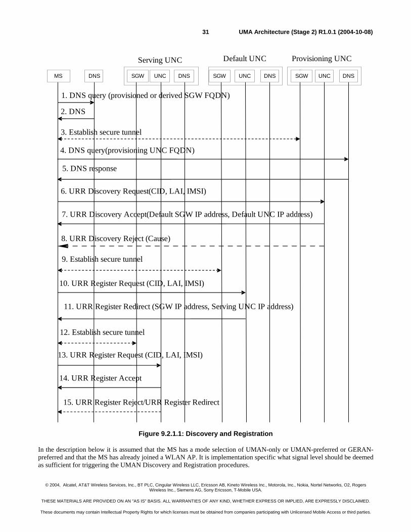
© 2004, Alcatel, AT&T Wireless Services, Inc., BT PLC, Cingular Wireless LLC, Ericsson AB, Kineto Wireless Inc., Motorola, Inc., Nokia, Nortel Networks, O2, Rogers Wireless Inc., Siemens AG, Sony Ericsson, T-Mobile USA.
THESE MATERIALS ARE PROVIDED ON AN "AS IS" BASIS. ALL WARRANTIES OF ANY KIND, WHETHER EXPRESS OR IMPLIED, ARE EXPRESSLY DISCLAIMED.
These documents may contain Intellectual Property Rights for which licenses must be obtained from companies participating with Unlicensed Mobile Access or third parties.
UMA Architecture (Stage 2) R1.0.1 (2004-10-08)31
1. DNS query (provisioned or derived SGW FQDN)
Default UNCServing UNC
2. DNS
3. Establish secure tunnel
4. DNS query(provisioning UNC FQDN)
5. DNS response
6. URR Discovery Request(CID, LAI, IMSI)
7. URR Discovery Accept(Default SGW IP address, Default UNC IP address)
8. URR Discovery Reject (Cause)
MS DNS SGW UNC DNS SGW UNC DNS SGW UNC DNS
Provisioning UNC
9. Establish secure tunnel
10. URR Register Request (CID, LAI, IMSI)
11. URR Register Redirect (SGW IP address, Serving UNC IP address)
12. Establish secure tunnel
13. URR Register Request (CID, LAI, IMSI)
14. URR Register Accept
15. URR Register Reject/URR Register Redirect
Figure 9.2.1.1: Discovery and Registration
In the description below it is assumed that the MS has a mode selection of UMAN-only or UMAN-preferred or GERAN-preferred and that the MS has already joined a WLAN AP. It is implementation specific what signal level should be deemed as sufficient for triggering the UMAN Discovery and Registration procedures.
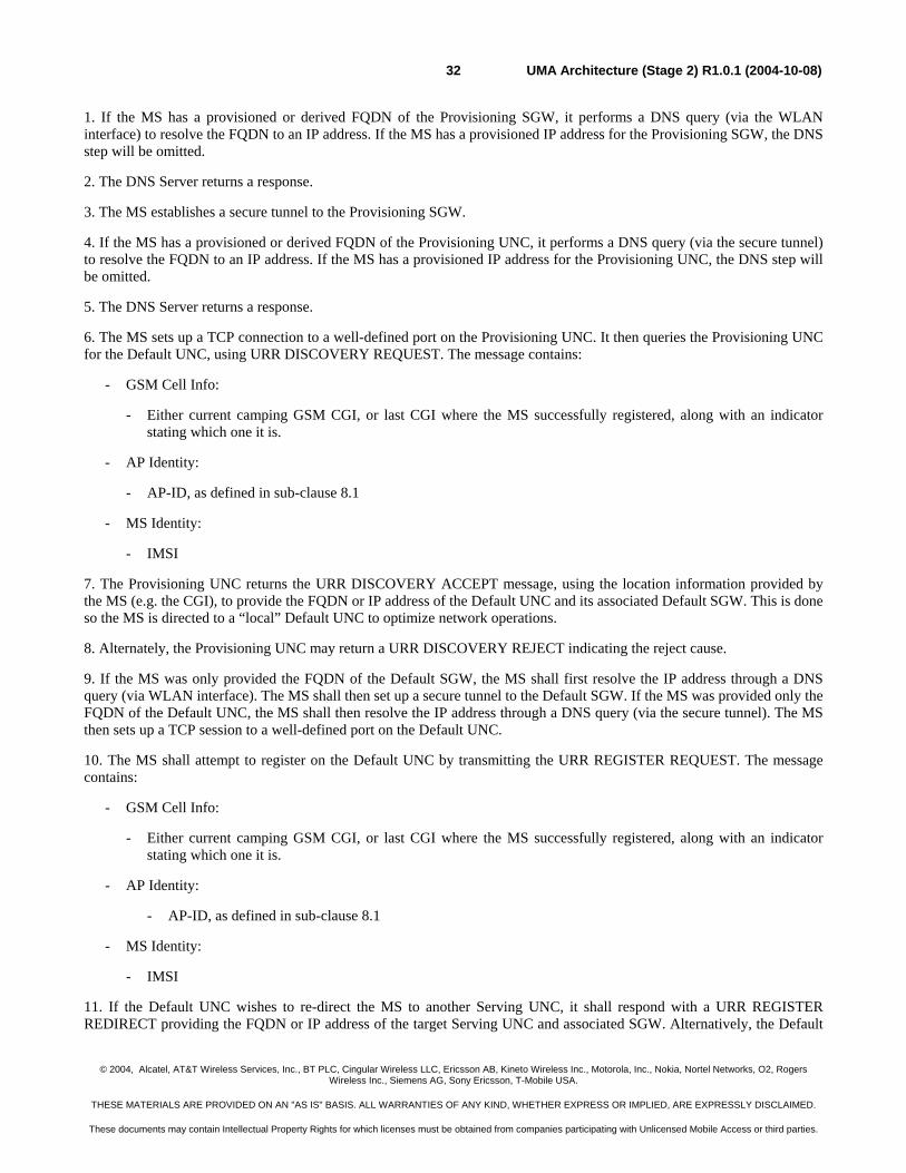
© 2004, Alcatel, AT&T Wireless Services, Inc., BT PLC, Cingular Wireless LLC, Ericsson AB, Kineto Wireless Inc., Motorola, Inc., Nokia, Nortel Networks, O2, Rogers Wireless Inc., Siemens AG, Sony Ericsson, T-Mobile USA.
THESE MATERIALS ARE PROVIDED ON AN "AS IS" BASIS. ALL WARRANTIES OF ANY KIND, WHETHER EXPRESS OR IMPLIED, ARE EXPRESSLY DISCLAIMED.
These documents may contain Intellectual Property Rights for which licenses must be obtained from companies participating with Unlicensed Mobile Access or third parties.
UMA Architecture (Stage 2) R1.0.1 (2004-10-08)32
1. If the MS has a provisioned or derived FQDN of the Provisioning SGW, it performs a DNS query (via the WLAN interface) to resolve the FQDN to an IP address. If the MS has a provisioned IP address for the Provisioning SGW, the DNS step will be omitted.
2. The DNS Server returns a response.
3. The MS establishes a secure tunnel to the Provisioning SGW.
4. If the MS has a provisioned or derived FQDN of the Provisioning UNC, it performs a DNS query (via the secure tunnel) to resolve the FQDN to an IP address. If the MS has a provisioned IP address for the Provisioning UNC, the DNS step will be omitted.
5. The DNS Server returns a response.
6. The MS sets up a TCP connection to a well-defined port on the Provisioning UNC. It then queries the Provisioning UNC for the Default UNC, using URR DISCOVERY REQUEST. The message contains:
- GSM Cell Info:
- Either current camping GSM CGI, or last CGI where the MS successfully registered, along with an indicator stating which one it is.
- AP Identity:
- AP-ID, as defined in sub-clause 8.1
- MS Identity:
- IMSI
7. The Provisioning UNC returns the URR DISCOVERY ACCEPT message, using the location information provided by the MS (e.g. the CGI), to provide the FQDN or IP address of the Default UNC and its associated Default SGW. This is done so the MS is directed to a “local” Default UNC to optimize network operations.
8. Alternately, the Provisioning UNC may return a URR DISCOVERY REJECT indicating the reject cause.
9. If the MS was only provided the FQDN of the Default SGW, the MS shall first resolve the IP address through a DNS query (via WLAN interface). The MS shall then set up a secure tunnel to the Default SGW. If the MS was provided only the FQDN of the Default UNC, the MS shall then resolve the IP address through a DNS query (via the secure tunnel). The MS then sets up a TCP session to a well-defined port on the Default UNC.
10. The MS shall attempt to register on the Default UNC by transmitting the URR REGISTER REQUEST. The message contains:
- GSM Cell Info:
- Either current camping GSM CGI, or last CGI where the MS successfully registered, along with an indicator stating which one it is.
- AP Identity:
- AP-ID, as defined in sub-clause 8.1
- MS Identity:
- IMSI
11. If the Default UNC wishes to re-direct the MS to another Serving UNC, it shall respond with a URR REGISTER REDIRECT providing the FQDN or IP address of the target Serving UNC and associated SGW. Alternatively, the Default
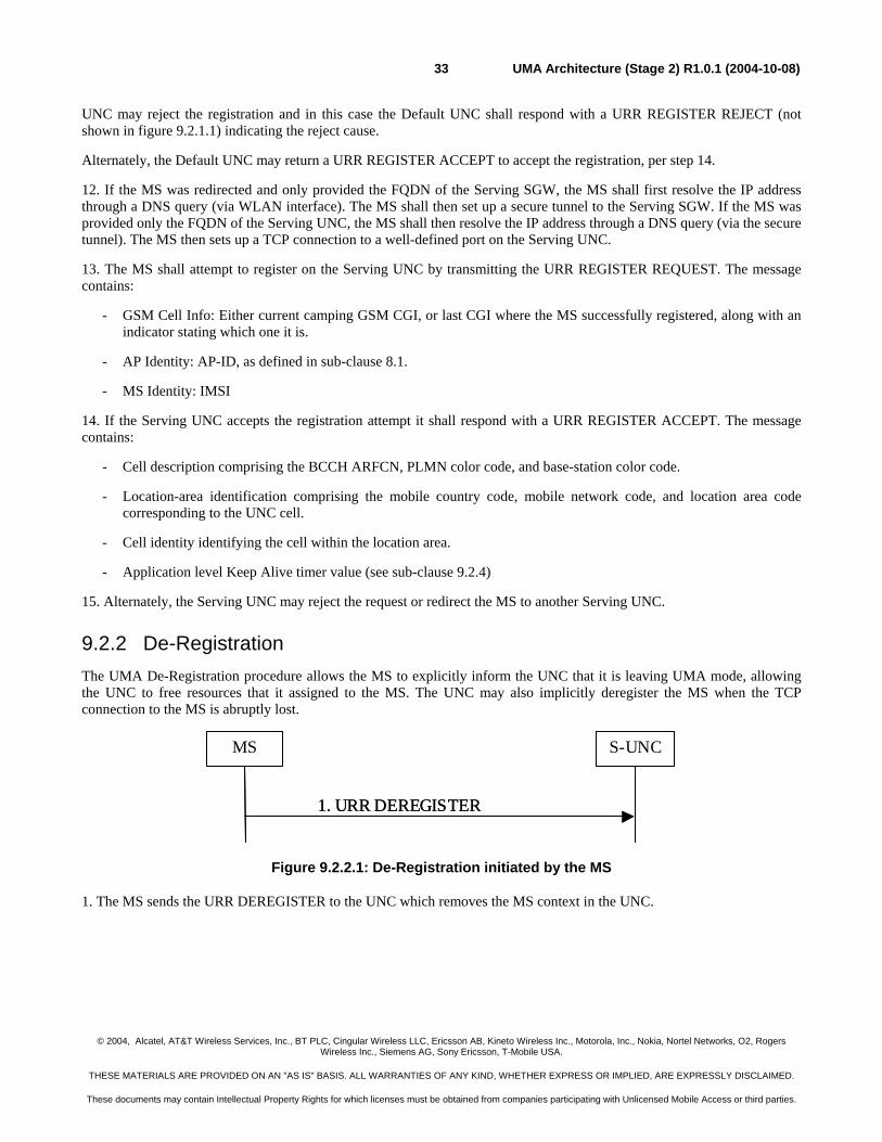
© 2004, Alcatel, AT&T Wireless Services, Inc., BT PLC, Cingular Wireless LLC, Ericsson AB, Kineto Wireless Inc., Motorola, Inc., Nokia, Nortel Networks, O2, Rogers Wireless Inc., Siemens AG, Sony Ericsson, T-Mobile USA.
THESE MATERIALS ARE PROVIDED ON AN "AS IS" BASIS. ALL WARRANTIES OF ANY KIND, WHETHER EXPRESS OR IMPLIED, ARE EXPRESSLY DISCLAIMED.
These documents may contain Intellectual Property Rights for which licenses must be obtained from companies participating with Unlicensed Mobile Access or third parties.
UMA Architecture (Stage 2) R1.0.1 (2004-10-08)33
UNC may reject the registration and in this case the Default UNC shall respond with a URR REGISTER REJECT (not shown in figure 9.2.1.1) indicating the reject cause.
Alternately, the Default UNC may return a URR REGISTER ACCEPT to accept the registration, per step 14.
12. If the MS was redirected and only provided the FQDN of the Serving SGW, the MS shall first resolve the IP address through a DNS query (via WLAN interface). The MS shall then set up a secure tunnel to the Serving SGW. If the MS was provided only the FQDN of the Serving UNC, the MS shall then resolve the IP address through a DNS query (via the secure tunnel). The MS then sets up a TCP connection to a well-defined port on the Serving UNC.
13. The MS shall attempt to register on the Serving UNC by transmitting the URR REGISTER REQUEST. The message contains:
- GSM Cell Info: Either current camping GSM CGI, or last CGI where the MS successfully registered, along with an indicator stating which one it is.
- AP Identity: AP-ID, as defined in sub-clause 8.1.
- MS Identity: IMSI
14. If the Serving UNC accepts the registration attempt it shall respond with a URR REGISTER ACCEPT. The message contains:
- Cell description comprising the BCCH ARFCN, PLMN color code, and base-station color code.
- Location-area identification comprising the mobile country code, mobile network code, and location area code corresponding to the UNC cell.
- Cell identity identifying the cell within the location area.
- Application level Keep Alive timer value (see sub-clause 9.2.4)
15. Alternately, the Serving UNC may reject the request or redirect the MS to another Serving UNC.
9.2.2 De-Registration The UMA De-Registration procedure allows the MS to explicitly inform the UNC that it is leaving UMA mode, allowing the UNC to free resources that it assigned to the MS. The UNC may also implicitly deregister the MS when the TCP connection to the MS is abruptly lost.
S-UNCMS
1. URR DEREGISTER
S-UNCMS
1. URR DEREGISTER
Figure 9.2.2.1: De-Registration initiated by the MS
1. The MS sends the URR DEREGISTER to the UNC which removes the MS context in the UNC.
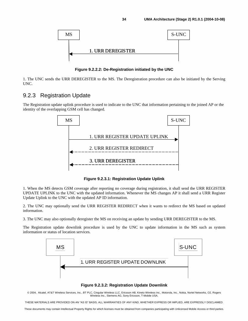
© 2004, Alcatel, AT&T Wireless Services, Inc., BT PLC, Cingular Wireless LLC, Ericsson AB, Kineto Wireless Inc., Motorola, Inc., Nokia, Nortel Networks, O2, Rogers Wireless Inc., Siemens AG, Sony Ericsson, T-Mobile USA.
THESE MATERIALS ARE PROVIDED ON AN "AS IS" BASIS. ALL WARRANTIES OF ANY KIND, WHETHER EXPRESS OR IMPLIED, ARE EXPRESSLY DISCLAIMED.
These documents may contain Intellectual Property Rights for which licenses must be obtained from companies participating with Unlicensed Mobile Access or third parties.
UMA Architecture (Stage 2) R1.0.1 (2004-10-08)34
S-UNCMS
1. URR DEREGISTER
S-UNCMS
1. URR DEREGISTER
Figure 9.2.2.2: De-Registration initiated by the UNC
1. The UNC sends the URR DEREGISTER to the MS. The Deregistration procedure can also be initiated by the Serving UNC.
9.2.3 Registration Update The Registration update uplink procedure is used to indicate to the UNC that information pertaining to the joined AP or the identity of the overlapping GSM cell has changed.
Figure 9.2.3.1: Registration Update Uplink
1. When the MS detects GSM coverage after reporting no coverage during registration, it shall send the URR REGISTER UPDATE UPLINK to the UNC with the updated information. Whenever the MS changes AP it shall send a URR Register Update Uplink to the UNC with the updated AP ID information.
2. The UNC may optionally send the URR REGISTER REDIRECT when it wants to redirect the MS based on updated information.
3. The UNC may also optionally deregister the MS on receiving an update by sending URR DEREGISTER to the MS.
The Registration update downlink procedure is used by the UNC to update information in the MS such as system information or status of location services.
MS
1. URR REGISTER UPDATE DOWNLINK
S-UNC
Figure 9.2.3.2: Registration Update Downlink
S-UNC
2. URR REGISTER REDIRECT
MS
1. URR REGISTER UPDATE UPLINK
3. URR DEREGISTER
S-UNCMS
3. URR DEREGISTER
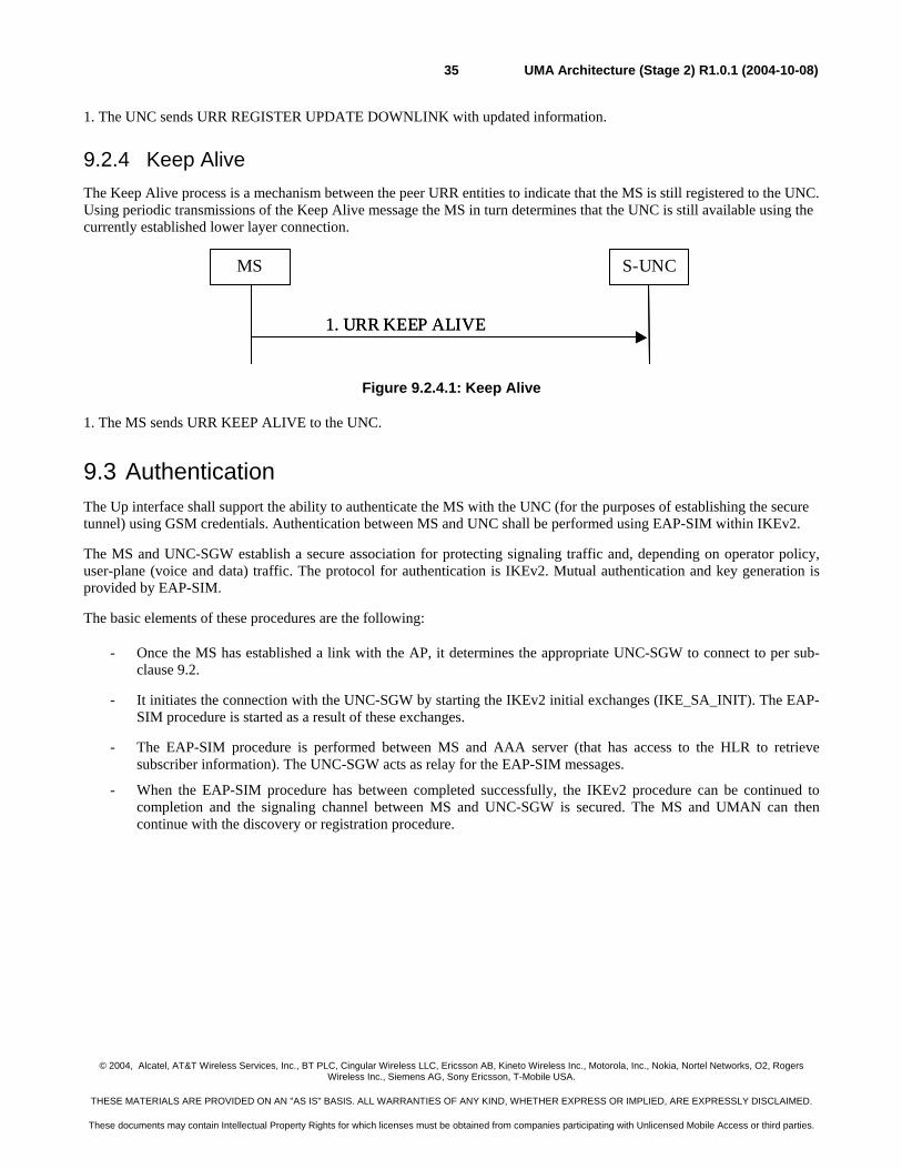
© 2004, Alcatel, AT&T Wireless Services, Inc., BT PLC, Cingular Wireless LLC, Ericsson AB, Kineto Wireless Inc., Motorola, Inc., Nokia, Nortel Networks, O2, Rogers Wireless Inc., Siemens AG, Sony Ericsson, T-Mobile USA.
THESE MATERIALS ARE PROVIDED ON AN "AS IS" BASIS. ALL WARRANTIES OF ANY KIND, WHETHER EXPRESS OR IMPLIED, ARE EXPRESSLY DISCLAIMED.
These documents may contain Intellectual Property Rights for which licenses must be obtained from companies participating with Unlicensed Mobile Access or third parties.
UMA Architecture (Stage 2) R1.0.1 (2004-10-08)35
1. The UNC sends URR REGISTER UPDATE DOWNLINK with updated information.
9.2.4 Keep Alive The Keep Alive process is a mechanism between the peer URR entities to indicate that the MS is still registered to the UNC. Using periodic transmissions of the Keep Alive message the MS in turn determines that the UNC is still available using the currently established lower layer connection.
S-UNCMS
1. URR KEEP ALIVE
S-UNCMS
1. URR KEEP ALIVE
Figure 9.2.4.1: Keep Alive
1. The MS sends URR KEEP ALIVE to the UNC.
9.3 Authentication The Up interface shall support the ability to authenticate the MS with the UNC (for the purposes of establishing the secure tunnel) using GSM credentials. Authentication between MS and UNC shall be performed using EAP-SIM within IKEv2.
The MS and UNC-SGW establish a secure association for protecting signaling traffic and, depending on operator policy, user-plane (voice and data) traffic. The protocol for authentication is IKEv2. Mutual authentication and key generation is provided by EAP-SIM.
The basic elements of these procedures are the following:
- Once the MS has established a link with the AP, it determines the appropriate UNC-SGW to connect to per sub-clause 9.2.
- It initiates the connection with the UNC-SGW by starting the IKEv2 initial exchanges (IKE_SA_INIT). The EAP-SIM procedure is started as a result of these exchanges.
- The EAP-SIM procedure is performed between MS and AAA server (that has access to the HLR to retrieve subscriber information). The UNC-SGW acts as relay for the EAP-SIM messages.
- When the EAP-SIM procedure has between completed successfully, the IKEv2 procedure can be continued to completion and the signaling channel between MS and UNC-SGW is secured. The MS and UMAN can then continue with the discovery or registration procedure.
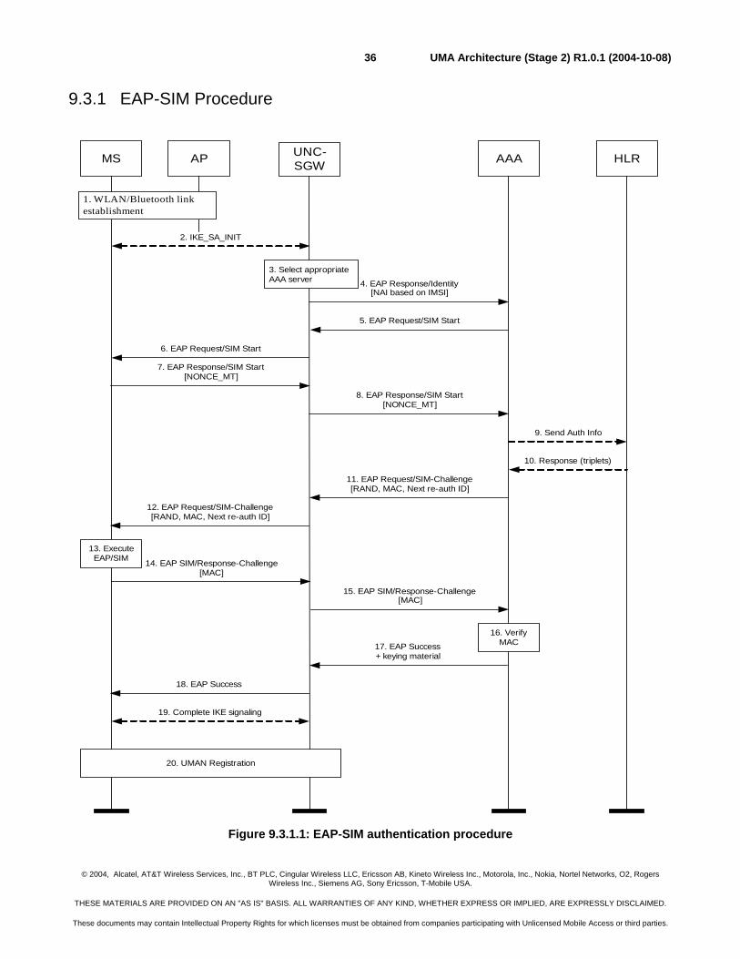
© 2004, Alcatel, AT&T Wireless Services, Inc., BT PLC, Cingular Wireless LLC, Ericsson AB, Kineto Wireless Inc., Motorola, Inc., Nokia, Nortel Networks, O2, Rogers Wireless Inc., Siemens AG, Sony Ericsson, T-Mobile USA.
THESE MATERIALS ARE PROVIDED ON AN "AS IS" BASIS. ALL WARRANTIES OF ANY KIND, WHETHER EXPRESS OR IMPLIED, ARE EXPRESSLY DISCLAIMED.
These documents may contain Intellectual Property Rights for which licenses must be obtained from companies participating with Unlicensed Mobile Access or third parties.
UMA Architecture (Stage 2) R1.0.1 (2004-10-08)36
9.3.1 EAP-SIM Procedure
AP HLRAAAUNC-SGWMS
1. WLAN/Bluetooth linkestablishment
2. IKE_SA_INIT
3. Select appropriateAAA server 4. EAP Response/Identity
[NAI based on IMSI]
5. EAP Request/SIM Start
6. EAP Request/SIM Start
7. EAP Response/SIM Start[NONCE_MT]
8. EAP Response/SIM Start[NONCE_MT]
9. Send Auth Info
10. Response (triplets)
11. EAP Request/SIM-Challenge[RAND, MAC, Next re-auth ID]
12. EAP Request/SIM-Challenge[RAND, MAC, Next re-auth ID]
13. ExecuteEAP/SIM 14. EAP SIM/Response-Challenge
[MAC]
15. EAP SIM/Response-Challenge[MAC]
16. VerifyMAC17. EAP Success
+ keying material
18. EAP Success
19. Complete IKE signaling
20. UMAN Registration
Figure 9.3.1.1: EAP-SIM authentication procedure
© 2004, Alcatel, AT&T Wireless Services, Inc., BT PLC, Cingular Wireless LLC, Ericsson AB, Kineto Wireless Inc., Motorola, Inc., Nokia, Nortel Networks, O2, Rogers Wireless Inc., Siemens AG, Sony Ericsson, T-Mobile USA.
THESE MATERIALS ARE PROVIDED ON AN "AS IS" BASIS. ALL WARRANTIES OF ANY KIND, WHETHER EXPRESS OR IMPLIED, ARE EXPRESSLY DISCLAIMED.
These documents may contain Intellectual Property Rights for which licenses must be obtained from companies participating with Unlicensed Mobile Access or third parties.
UMA Architecture (Stage 2) R1.0.1 (2004-10-08)37
The EAP-SIM authentication mechanism is specified in [EAP SIM]. This section describes how this mechanism is used in UMA. The procedure is based on the procedure defined in [EAP SIM].
1. The MS joins an AP.
2. The MS obtains the IP address of the UNC-SGW, and initializes the IKEv2 authentication procedure by starting the IKE_SA_INIT exchange. It indicates the desire to use EAP by leaving out the AUTH payload from message 3 of the IKE_AUTH exchange, and the initiator identity is composed compliant with the Network Access Identifier (NAI) format specified in RFC 2486, which contains the IMSI.
3. The UNC-SGW communicates with the local AAA server through the Wm interface, which in turn determines the proper AAA Server based on the realm part of the NAI. The routing path may include one or several AAA proxies (not shown in the figure).
4. The UNC-SGW sends an EAP Response/Identity message to the AAA server, containing the identity included in the third IKE message. This triggers the start of EAP-SIM.
5. The AAA Server identifies the subscriber as a candidate for authentication with EAP-SIM, based on the received identity, and sends the EAP Request/SIM-Start packet to UNC-SGW.
6. The UNC-SGW sends the EAP Request/SIM-Start packet to MS.
7. The MS chooses a fresh random number NONCE_MT. The random number is used in network authentication. The MS sends the EAP Response/SIM-Start packet, containing NONCE_MT, to the UNC-SGW.
8. The UNC-SGW sends the EAP Response/SIM-Start packet to the AAA Server.
9. The AAA server requests authentication data from the HLR, based on the IMSI. Note that the AAA server could instead use cached triplets previously retrieved from the HLR to continue the authentication process.
10. The AAA server receives multiple triplets from the HLR.
11. The AAA server formulates an EAP-SIM/Challenge with multiple RAND challenges, and includes a message authentication code (MAC) whose master key is computed based on the associated Kc keys, as well as the NONCE_MT. A new re-authentication identity may be chosen and protected (i.e. encrypted and integrity protected) using EAP-SIM generated keying material. The AAA Server sends this RAND, MAC and re-authentication identity to the UNC-SGW in the EAP Request/SIM-Challenge message.
12. The UNC-SGW sends the EAP Request/SIM-Challenge message to the MS.
13. The MS runs N times the GSM A3/A8 algorithm in the SIM, once for each received RAND. This computing gives N SRES and Kc values. The MS calculates its copy of the network authentication MAC with the newly derived keying material and checks that it is equal with the received MAC. If the MAC is incorrect, the network authentication has failed and the MS cancels the authentication. The MS continues the authentication exchange only if the MAC is correct. The MS calculates a new MAC with the new keying material covering the EAP message concatenated to the N SRES responses. If a re-authentication ID was received, then the MS stores this ID for future authentications.
14. The MS sends EAP Response/SIM-Challenge containing calculated MAC to the UNC-SGW.
15. The UNC-SGW sends the EAP Response/SIM-Challenge packet to the AAA Server.
16. The AAA Server verifies that its copy of the response MAC is equal to the received MAC.
17. If the comparison in step 18 is successful, then the AAA Server sends the EAP Success message to the UNC-SGW. The AAA Server includes derived keying material for confidentiality and/or integrity protection between MS and UNC-SGW, in the underlying AAA protocol message (i.e. not at EAP level).
18. The UNC-SGW informs the MS about the successful authentication with the EAP Success message.
© 2004, Alcatel, AT&T Wireless Services, Inc., BT PLC, Cingular Wireless LLC, Ericsson AB, Kineto Wireless Inc., Motorola, Inc., Nokia, Nortel Networks, O2, Rogers Wireless Inc., Siemens AG, Sony Ericsson, T-Mobile USA.
THESE MATERIALS ARE PROVIDED ON AN "AS IS" BASIS. ALL WARRANTIES OF ANY KIND, WHETHER EXPRESS OR IMPLIED, ARE EXPRESSLY DISCLAIMED.
These documents may contain Intellectual Property Rights for which licenses must be obtained from companies participating with Unlicensed Mobile Access or third parties.
UMA Architecture (Stage 2) R1.0.1 (2004-10-08)38
19. Now the EAP-SIM exchange has been successfully completed, the IKE signaling can be completed
20. The Secure Association between MS and UNC-SGW has been completed and the MS can continue with the discovery or registration procedure.
9.3.2 Fast Re-authentication Mechanism When the authentication process is performed frequently, especially with a large number of connected Mobile Stations, performing fast re-authentication can reduce the network load resulting from this authentication. The fast re-authentication process allows the AAA server to authenticate a user based on keys derived from the last full authentication process.
The MS and UNC-SGW can use a procedure for fast re-authentication in order to re-authenticate an MS e.g. when setting up a new SA because the IP address of the MS has changed as a result of a handover between APs connected to different IP subnets. Fast re-authentication is provided by EAP-SIM, and does not make use of the GSM A3/A8 procedures. The MS may use the re-authentication ID in the IKE_SA_INIT. The decision to make use of the fast re-authentication procedure is taken by the AAA server.
The basic elements of these procedures are the following:
− The MS initiates a new SA with a UNC-SGW that it was previously connected to and uses the re-authentication ID (re-authentication ID received during the previous full authentication procedure) in the IKE_SA_INIT exchange. The EAP-SIM procedure is started as a result of these exchanges.
− The AAA server and MS re-authenticate each other based on the keys derived on the preceding full authentication.
9.3.2.1 EAP-SIM Procedure for Fast Re-authentication The EAP-SIM specification includes support for fast re-authentication. The use of this mechanism may be subject to operator policy.
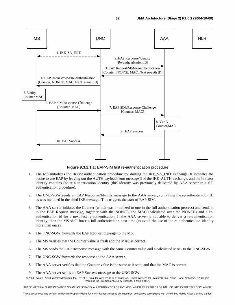
© 2004, Alcatel, AT&T Wireless Services, Inc., BT PLC, Cingular Wireless LLC, Ericsson AB, Kineto Wireless Inc., Motorola, Inc., Nokia, Nortel Networks, O2, Rogers Wireless Inc., Siemens AG, Sony Ericsson, T-Mobile USA.
THESE MATERIALS ARE PROVIDED ON AN "AS IS" BASIS. ALL WARRANTIES OF ANY KIND, WHETHER EXPRESS OR IMPLIED, ARE EXPRESSLY DISCLAIMED.
These documents may contain Intellectual Property Rights for which licenses must be obtained from companies participating with Unlicensed Mobile Access or third parties.
UMA Architecture (Stage 2) R1.0.1 (2004-10-08)39
2. EAP Response/Identity[Re-authentication ID]
3. EAP Request/SIM/Re-authentication[Counter, NONCE, MAC, Next re-auth ID]
4. EAP Request/SIM/Re-authentication[Counter, NONCE, MAC, Next re-auth ID]
6. EAP SIM/Response-Challenge[Counter, MAC] 7. EAP SIM/Response-Challenge
[Counter, MAC]
9. EAP Success
10. EAP Success
1. IKE_SA_INIT
MS UNC AAA HLR
8. VerifyCounter,MAC
5. VerifyCounter,MAC
Figure 9.3.2.1.1: EAP-SIM fast re-authentication procedure
1. The MS initializes the IKEv2 authentication procedure by starting the IKE_SA_INIT exchange. It indicates the desire to use EAP by leaving out the AUTH payload from message 3 of the IKE_AUTH exchange, and the initiator identity contains the re-authentication identity (this identity was previously delivered by AAA server in a full authentication procedure).
2. The UNC-SGW sends an EAP Response/Identity message to the AAA server, containing the re-authentication ID as was included in the third IKE message. This triggers the start of EAP-SIM.
3. The AAA server initiates the Counter (which was initialized to one in the full authentication process) and sends it in the EAP Request message, together with the NONCE, the MAC (calculated over the NONCE) and a re-authentication id for a next fast re-authentication. If the AAA server is not able to deliver a re-authentication identity, then the MS shall force a full-authentication next time (to avoid the use of the re-authentication identity more than once).
4. The UNC-SGW forwards the EAP Request message to the MS.
5. The MS verifies that the Counter value is fresh and the MAC is correct.
6. The MS sends the EAP Response message with the same Counter value and a calculated MAC to the UNC-SGW.
7. The UNC-SGW forwards the response to the AAA server.
8. The AAA server verifies that the Counter value is the same as it sent, and that the MAC is correct.
9. The AAA server sends an EAP Success message to the UNC-SGW.
© 2004, Alcatel, AT&T Wireless Services, Inc., BT PLC, Cingular Wireless LLC, Ericsson AB, Kineto Wireless Inc., Motorola, Inc., Nokia, Nortel Networks, O2, Rogers Wireless Inc., Siemens AG, Sony Ericsson, T-Mobile USA.
THESE MATERIALS ARE PROVIDED ON AN "AS IS" BASIS. ALL WARRANTIES OF ANY KIND, WHETHER EXPRESS OR IMPLIED, ARE EXPRESSLY DISCLAIMED.
These documents may contain Intellectual Property Rights for which licenses must be obtained from companies participating with Unlicensed Mobile Access or third parties.
UMA Architecture (Stage 2) R1.0.1 (2004-10-08)40
10. The UNC-SGW forwards the EAP Success message to the MS.
9.4 Encryption All signaling and user plane traffic over the Up interface shall be sent through the IPsec tunnel that is established as a result of the authentication procedure. Encryption shall use the negotiated cryptographic algorithm, based on core network policy, enforced by the UNC-SGW.
The MS and UNC-SGW set up one Secure Association through which all traffic is sent. A single negotiated ciphering algorithm is applied to the connection.
9.4.1 Establishment of a Secure Association After the authentication procedure (sub-clause 9.3), the MS shall request an IP address on the network protected by the UNC Security gateway (i.e. the public IP interface of the UNC). The MS shall set up one IPsec Security Association (SA) between MS and UNC-SGW.
The MS shall initiate the creation of the SA i.e. it shall act as initiator in the Traffic Selector negotiation. The protocol ID field in the Traffic Selectors (TS) shall be set to zero, indicating that the protocol ID is not relevant. The IP address range in the TSi shall be set to the address assigned to the MS (within the network protected by the IPsec gateway). The IP address range in the TSr shall be set to 0.0.0.0 – 255.255.255.255. The MS shall send a periodic keep-alive message in order to maintain the secure tunnel, per [IPSec NAT].
9.4.1.1 Security Configuration
All signaling and user plane data over the Up interface between MS and UNC shall be sent through the SA.
The ciphering mode is negotiated during connection establishment. During setup of the SA, the MS includes a list of supported encryption algorithms as part of the IKE signaling, which include the mandatory and supported optional algorithms defined in the IPsec profile, and NULL encryption. The UNC-SGW selects one of these algorithms, and signals this to the MS.
When NULL encryption is applied, both signaling and user-plane traffic is sent unencrypted. This configuration can be selected e.g. when the connection between the unlicensed access network and the UNC is under operator control. The integrity algorithm is the same as for either configuration i.e. non-ciphered traffic is still integrity protected.
9.4.1.2 GSM to UMAN Handover
When the MS detects UMA coverage, it sets up a connection with the UMAN, thereby establishing a IPSec Secure Association with the UNC-SGW.
9.4.1.3 UMAN to GSM Handover
The MS shall perform the necessary security procedures per the GERAN specifications.
9.4.1.4 Intra-UMAN Handover
When the MS has changed point of attachment in the unlicensed access network, including a change of IP address (because the MS changed subnet), the MS may perform the EAP-SIM Fast Re-authentication procedure.
The MS shall initiate the setup of a new SA with the UNC, and may use the re-authentication ID as identity during this operation. If the re-authentication ID is used, then the EAP-SIM fast re-authentication procedure is used depending on the AAA server policy. For the rest, the procedure is identical to the one outlined in sub-clause 9.3. The new SA replaces the previous SA that was established using the previous MS IP address.
© 2004, Alcatel, AT&T Wireless Services, Inc., BT PLC, Cingular Wireless LLC, Ericsson AB, Kineto Wireless Inc., Motorola, Inc., Nokia, Nortel Networks, O2, Rogers Wireless Inc., Siemens AG, Sony Ericsson, T-Mobile USA.
THESE MATERIALS ARE PROVIDED ON AN "AS IS" BASIS. ALL WARRANTIES OF ANY KIND, WHETHER EXPRESS OR IMPLIED, ARE EXPRESSLY DISCLAIMED.
These documents may contain Intellectual Property Rights for which licenses must be obtained from companies participating with Unlicensed Mobile Access or third parties.
UMA Architecture (Stage 2) R1.0.1 (2004-10-08)41
9.5 Rove-in On entering UMA coverage the MS may choose to join an AP depending on user preferences and service provider configuration. Following UMAN discovery, the MS shall initiate registration with the UMAN per sub-clause 9.2.
Following successful registration, the MS switches to UMA mode wherein the serving RR entity is UMA-RR. UMA-RR shall report the appropriate system information received following successful registration from the serving UNC, to the NAS layers. GSM-RR is detached from the RR-SAP.
Since it is detached from the NAS and not serving upper layers, GSM-RR should not inform the MM layer about any cell re-selection and/or the change of system information of the current camping cell; also, any detection of newly found GSM PLMN shall not trigger NAS to change selected PLMN. MM shall consider the UMA cell as the current serving cell.
GSM RR should not act on any received paging request message.
9.6 Rove-out These procedures are applicable for the following conditions and mode selection preferences (per sub-clause 9.1.1):
- UMAN-only, and MS leaves UMA coverage
- UMAN-preferred, and MS leaves UMA coverage
- GERAN-preferred, and a GSM PLMN becomes available, or MS leaves UMA coverage
When the MS leaves UMA coverage, depending on prevailing circumstances the MS may be able to de-register first with the UMAN indicating that it is leaving UMA coverage.
For the UMAN-preferred and GERAN-preferred mode selections, the MS shall detach UMA-RR from NAS and re-attach GSM-RR to NAS and re-store normal GSM-RR functionality.
For the UMA-only mode selection, UMA-RR remains attached to NAS and the MS stays in UMA mode (in “No Service” condition).
9.7 Ciphering Configuration The call flow showing message sequences for ciphering configuration is shown in Figure 9.7.1.
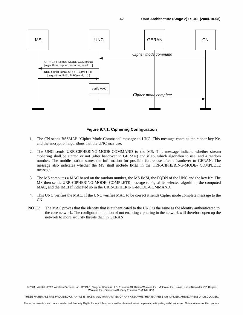
© 2004, Alcatel, AT&T Wireless Services, Inc., BT PLC, Cingular Wireless LLC, Ericsson AB, Kineto Wireless Inc., Motorola, Inc., Nokia, Nortel Networks, O2, Rogers Wireless Inc., Siemens AG, Sony Ericsson, T-Mobile USA.
THESE MATERIALS ARE PROVIDED ON AN "AS IS" BASIS. ALL WARRANTIES OF ANY KIND, WHETHER EXPRESS OR IMPLIED, ARE EXPRESSLY DISCLAIMED.
These documents may contain Intellectual Property Rights for which licenses must be obtained from companies participating with Unlicensed Mobile Access or third parties.
UMA Architecture (Stage 2) R1.0.1 (2004-10-08)42
Cipher mode command
URR-CIPHERING-MODE-COMMAND[algorithms, cipher response, rand, …]
Cipher mode complete
MS UNC GERAN CN
Verify MAC
URR-CIPHERING-MODE-COMPLETE[ algorithm, IMEI, MAC(rand, …) ]
Figure 9.7.1: Ciphering Configuration
1. The CN sends BSSMAP "Cipher Mode Command" message to UNC. This message contains the cipher key Kc, and the encryption algorithms that the UNC may use.
2. The UNC sends URR-CIPHERING-MODE-COMMAND to the MS. This message indicate whether stream ciphering shall be started or not (after handover to GERAN) and if so, which algorithm to use, and a random number. The mobile station stores the information for possible future use after a handover to GERAN. The message also indicates whether the MS shall include IMEI in the URR-CIPHERING-MODE- COMPLETE message.
3. The MS computes a MAC based on the random number, the MS IMSI, the FQDN of the UNC and the key Kc. The MS then sends URR-CIPHERING-MODE- COMPLETE message to signal its selected algorithm, the computed MAC, and the IMEI if indicated so in the URR-CIPHERING-MODE-COMMAND.
4. This UNC verifies the MAC. If the UNC verifies MAC to be correct it sends Cipher mode complete message to the CN.
NOTE: The MAC proves that the identity that is authenticated to the UNC is the same as the identity authenticated to the core network. The configuration option of not enabling ciphering in the network will therefore open up the network to more security threats than in GERAN.
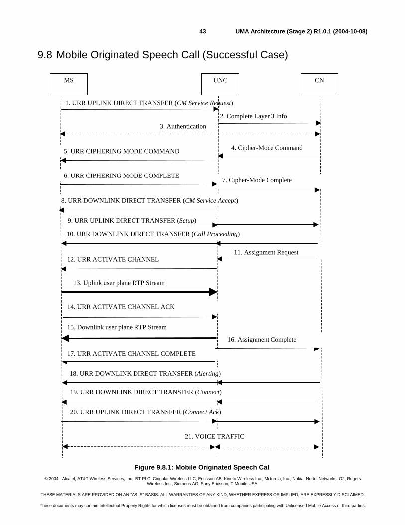
© 2004, Alcatel, AT&T Wireless Services, Inc., BT PLC, Cingular Wireless LLC, Ericsson AB, Kineto Wireless Inc., Motorola, Inc., Nokia, Nortel Networks, O2, Rogers Wireless Inc., Siemens AG, Sony Ericsson, T-Mobile USA.
THESE MATERIALS ARE PROVIDED ON AN "AS IS" BASIS. ALL WARRANTIES OF ANY KIND, WHETHER EXPRESS OR IMPLIED, ARE EXPRESSLY DISCLAIMED.
These documents may contain Intellectual Property Rights for which licenses must be obtained from companies participating with Unlicensed Mobile Access or third parties.
UMA Architecture (Stage 2) R1.0.1 (2004-10-08)43
9.8 Mobile Originated Speech Call (Successful Case)
Figure 9.8.1: Mobile Originated Speech Call
9. URR UPLINK DIRECT TRANSFER (Setup)
1. URR UPLINK DIRECT TRANSFER (CM Service Request)
3. Authentication
CN UNC MS
4. Cipher-Mode Command 5. URR CIPHERING MODE COMMAND
2. Complete Layer 3 Info
8. URR DOWNLINK DIRECT TRANSFER (CM Service Accept)
10. URR DOWNLINK DIRECT TRANSFER (Call Proceeding)
12. URR ACTIVATE CHANNEL
14. URR ACTIVATE CHANNEL ACK
13. Uplink user plane RTP Stream
15. Downlink user plane RTP Stream
17. URR ACTIVATE CHANNEL COMPLETE
21. VOICE TRAFFIC
18. URR DOWNLINK DIRECT TRANSFER (Alerting)
19. URR DOWNLINK DIRECT TRANSFER (Connect)
20. URR UPLINK DIRECT TRANSFER (Connect Ack)
11. Assignment Request
16. Assignment Complete
7. Cipher-Mode Complete 6. URR CIPHERING MODE COMPLETE
© 2004, Alcatel, AT&T Wireless Services, Inc., BT PLC, Cingular Wireless LLC, Ericsson AB, Kineto Wireless Inc., Motorola, Inc., Nokia, Nortel Networks, O2, Rogers Wireless Inc., Siemens AG, Sony Ericsson, T-Mobile USA.
THESE MATERIALS ARE PROVIDED ON AN "AS IS" BASIS. ALL WARRANTIES OF ANY KIND, WHETHER EXPRESS OR IMPLIED, ARE EXPRESSLY DISCLAIMED.
These documents may contain Intellectual Property Rights for which licenses must be obtained from companies participating with Unlicensed Mobile Access or third parties.
UMA Architecture (Stage 2) R1.0.1 (2004-10-08)44
1. Upon request from the user to originate a call, the MS sets up a new RR session, if needed, and sends the CM Service Request to the Serving UNC in the URR UPLINK DIRECT TRANSFER.
2. The Serving UNC establishes an SCCP connection to the CN and forwards the CM Service Request to the CN using the Complete Layer 3 Information. Subsequent layer-3 messages between mobile station and core network will be sent between Serving UNC and CN via DTAP.
3. The CN may optionally authenticate the MS using standard GERAN authentication procedures.
4. The CN may optionally update the ciphering parameters in the Serving UNC using the Cipher-Mode Command.
5. The Serving UNC signals the permitted ciphering algorithms to the MS using the URR CIPHERING-MODE COMMAND. These algorithms do not apply for Serving UNC. The MS stores this information for possible future use after a handover to GERAN.
6. The MS signals the selected ciphering algorithm in the URR CIPHERING-MODE COMPLETE message back to Serving UNC.
7. The Serving UNC signals the selected ciphering algorithm to the CN using Cipher-Mode Complete.
8. The CN sends the CM service accept message in the URR DOWNLINK DIRECT TRANSFER to the MS.
9. The MS sends the Setup message providing details on the call to the CN and its bearer capability and supported codecs. This message is contained within the URR UPLINK DIRECT TRANSFER.
10. The CN indicates it has received the call setup and it will accept no additional call-establishment information using the URR DOWNLINK DIRECT TRANSFER to convey the Call Proceeding indication to the MS.
11. The CN requests the Serving UNC to assign call resources using Assignment Request.
12. The Serving UNC sends the URR ACTIVATE CHANNEL to the MS including bearer path setup information such as:
- channel coding
- the UDP port & the IP address for the uplink stream
- the voice sample size
- the cipher mode (for use in case of subsequent handover to GERAN)
- Multi-rate information (if AMR codec is used).
13. The MS now establishes the RTP path to the Serving UNC. The MS has not connected the calling party to the audio path.
14. The MS sends the URR ACTIVATE CHANNEL ACK to the Serving UNC indicating the UDP port and IP address for the downlink stream.
15. The Serving UNC establishes the downlink RTP path between itself and the MS. The Serving UNC may start sending idle RTP/UDP packets to the MS.
16. The Serving UNC signals to the CN that the call resources have been allocated by sending an Assignment Complete message.
17. The Serving UNC signals the completion of the bearer path to the MS with the URR ACTIVATE CHANNEL COMPLETE message. An end-to-end audio path now exists between the MS and the CN. The MS can now connect the calling party to the audio path.
© 2004, Alcatel, AT&T Wireless Services, Inc., BT PLC, Cingular Wireless LLC, Ericsson AB, Kineto Wireless Inc., Motorola, Inc., Nokia, Nortel Networks, O2, Rogers Wireless Inc., Siemens AG, Sony Ericsson, T-Mobile USA.
THESE MATERIALS ARE PROVIDED ON AN "AS IS" BASIS. ALL WARRANTIES OF ANY KIND, WHETHER EXPRESS OR IMPLIED, ARE EXPRESSLY DISCLAIMED.
These documents may contain Intellectual Property Rights for which licenses must be obtained from companies participating with Unlicensed Mobile Access or third parties.
UMA Architecture (Stage 2) R1.0.1 (2004-10-08)45
18. The CN signals that the called party’s phone is ringing, via the Alerting message. If the mobile station has not connected the audio path to the calling party, it shall generate ring back to the calling party. Otherwise, the network-generated ring back will be returned to the calling party.
19. The CN signals that the called party has answered, via the Connect message. It connects the calling party to the audio path. If the mobile station is generating ring back, it stops and connects the calling party to the audio path.
20. The MS sends the Connect ACK in response, and the two parties are connected for the voice call.
21. Bi-directional voice traffic flows between the MS and CN through the Serving UNC.
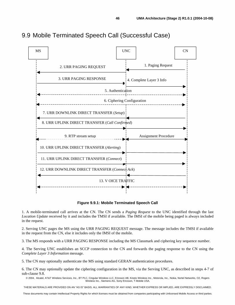
© 2004, Alcatel, AT&T Wireless Services, Inc., BT PLC, Cingular Wireless LLC, Ericsson AB, Kineto Wireless Inc., Motorola, Inc., Nokia, Nortel Networks, O2, Rogers Wireless Inc., Siemens AG, Sony Ericsson, T-Mobile USA.
THESE MATERIALS ARE PROVIDED ON AN "AS IS" BASIS. ALL WARRANTIES OF ANY KIND, WHETHER EXPRESS OR IMPLIED, ARE EXPRESSLY DISCLAIMED.
These documents may contain Intellectual Property Rights for which licenses must be obtained from companies participating with Unlicensed Mobile Access or third parties.
UMA Architecture (Stage 2) R1.0.1 (2004-10-08)46
9.9 Mobile Terminated Speech Call (Successful Case)
Figure 9.9.1: Mobile Terminated Speech Call
1. A mobile-terminated call arrives at the CN. The CN sends a Paging Request to the UNC identified through the last Location Update received by it and includes the TMSI if available. The IMSI of the mobile being paged is always included in the request.
2. Serving UNC pages the MS using the URR PAGING REQUEST message. The message includes the TMSI if available in the request from the CN, else it includes only the IMSI of the mobile.
3. The MS responds with a URR PAGING RESPONSE including the MS Classmark and ciphering key sequence number.
4. The Serving UNC establishes an SCCP connection to the CN and forwards the paging response to the CN using the Complete Layer 3 Information message.
5. The CN may optionally authenticate the MS using standard GERAN authentication procedures.
6. The CN may optionally update the ciphering configuration in the MS, via the Serving UNC, as described in steps 4-7 of sub-clause 9.8.
CN UNC MS
2. URR PAGING REQUEST
3. URR PAGING RESPONSE
7. URR DOWNLINK DIRECT TRANSFER (Setup)
8. URR UPLINK DIRECT TRANSFER (Call Confirmed)
13. V OICE TRAFFIC
10. URR UPLINK DIRECT TRANSFER (Alerting)
11. URR UPLINK DIRECT TRANSFER (Connect)
12. URR DOWNLINK DIRECT TRANSFER (Connect Ack)
4. Complete Layer 3 Info
1. Paging Request
5. Authentication
6. Ciphering Configuration
9. RTP stream setup Assignment Procedure
© 2004, Alcatel, AT&T Wireless Services, Inc., BT PLC, Cingular Wireless LLC, Ericsson AB, Kineto Wireless Inc., Motorola, Inc., Nokia, Nortel Networks, O2, Rogers Wireless Inc., Siemens AG, Sony Ericsson, T-Mobile USA.
THESE MATERIALS ARE PROVIDED ON AN "AS IS" BASIS. ALL WARRANTIES OF ANY KIND, WHETHER EXPRESS OR IMPLIED, ARE EXPRESSLY DISCLAIMED.
These documents may contain Intellectual Property Rights for which licenses must be obtained from companies participating with Unlicensed Mobile Access or third parties.
UMA Architecture (Stage 2) R1.0.1 (2004-10-08)47
7. The CN initiates call setup using the Setup message sent to the MS using the URR DOWNLINK DIRECT TRANSFER.
8. The MS responds with Call Confirmed using the URR UPLINK DIRECT TRANSFER after checking it's compatibility with the bearer service requested in the Setup and modifying the bearer service as needed. If the Setup included the signal information element, the MS alerts the user using the indicated signal, else the MS alerts the user after the successful configuration of the user plane.
9. The RTP stream between the Serving UNC and the MS is set up, per the procedure described in steps 11-17 in sub-clause 9.8.
10. The MS signals that it is alerting the user, via the Alerting message. The CN sends a corresponding alerting message to the calling party.
11. The MS signals that the called party has answered, via the Connect message. The CN sends a corresponding Connect message to the calling party and through connects the audio. The MS connects the user to the audio path.
12. The CN acknowledges via the Connect Ack message. The two parties on the call are connected on the audio path.
13. Bi-directional voice traffic flows between the MS and CN through the Serving UNC.
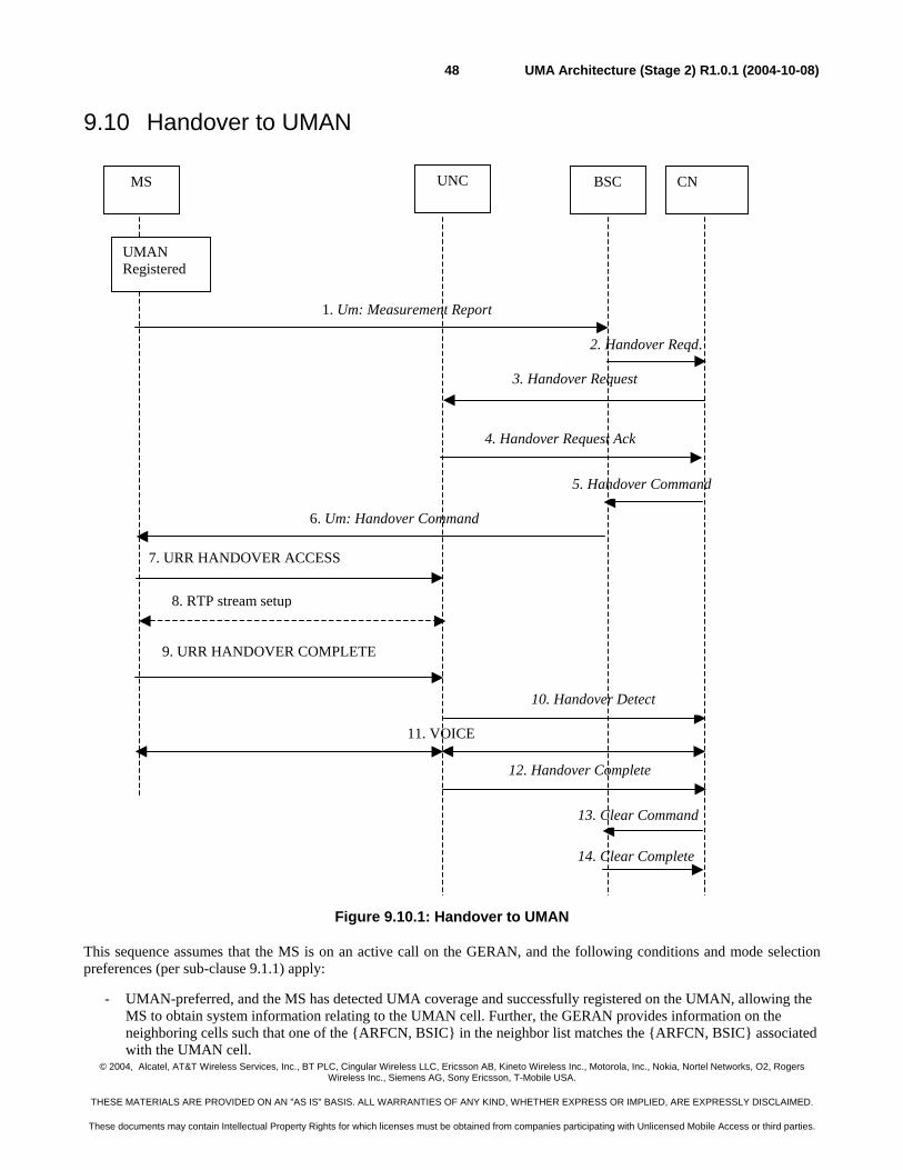
© 2004, Alcatel, AT&T Wireless Services, Inc., BT PLC, Cingular Wireless LLC, Ericsson AB, Kineto Wireless Inc., Motorola, Inc., Nokia, Nortel Networks, O2, Rogers Wireless Inc., Siemens AG, Sony Ericsson, T-Mobile USA.
THESE MATERIALS ARE PROVIDED ON AN "AS IS" BASIS. ALL WARRANTIES OF ANY KIND, WHETHER EXPRESS OR IMPLIED, ARE EXPRESSLY DISCLAIMED.
These documents may contain Intellectual Property Rights for which licenses must be obtained from companies participating with Unlicensed Mobile Access or third parties.
UMA Architecture (Stage 2) R1.0.1 (2004-10-08)48
9.10 Handover to UMAN
Figure 9.10.1: Handover to UMAN
This sequence assumes that the MS is on an active call on the GERAN, and the following conditions and mode selection preferences (per sub-clause 9.1.1) apply:
- UMAN-preferred, and the MS has detected UMA coverage and successfully registered on the UMAN, allowing the MS to obtain system information relating to the UMAN cell. Further, the GERAN provides information on the neighboring cells such that one of the {ARFCN, BSIC} in the neighbor list matches the {ARFCN, BSIC} associated with the UMAN cell.
12. Handover Complete
4. Handover Request Ack
2. Handover Reqd.
BSC UNC MS CN
1. Um: Measurement Report
3. Handover Request
5. Handover Command
6. Um: Handover Command
7. URR HANDOVER ACCESS
8. RTP stream setup
9. URR HANDOVER COMPLETE
10. Handover Detect
11. VOICE
UMAN Registered
13. Clear Command
14. Clear Complete
© 2004, Alcatel, AT&T Wireless Services, Inc., BT PLC, Cingular Wireless LLC, Ericsson AB, Kineto Wireless Inc., Motorola, Inc., Nokia, Nortel Networks, O2, Rogers Wireless Inc., Siemens AG, Sony Ericsson, T-Mobile USA.
THESE MATERIALS ARE PROVIDED ON AN "AS IS" BASIS. ALL WARRANTIES OF ANY KIND, WHETHER EXPRESS OR IMPLIED, ARE EXPRESSLY DISCLAIMED.
These documents may contain Intellectual Property Rights for which licenses must be obtained from companies participating with Unlicensed Mobile Access or third parties.
UMA Architecture (Stage 2) R1.0.1 (2004-10-08)49
1. The MS now begins to include UMA cell information in the Measurement Report to the GERAN. The MS reports the highest signal level for the UMA cell {ARFCN, BSIC}.
2. Based on MS measurement reports and other vendor specific BSS algorithms, GERAN decides to handover to the UMA cell, using an internal mapping of {ARFCN, BSIC} to CGI. The GERAN starts the handover preparation by sending a Handover Required message to the CN, identifying the target (UMAN) cell.
3. The CN requests the target UNC to allocate resources for the handover, using Handover Request.
4. The target UNC acknowledges the handover request, using Handover Request Acknowledge, indicating it can support the requested handover, and provides a Handover Command that indicates the radio channel to which the mobile station should be directed.
5. The CN forwards the Handover Command to the GERAN, completing the handover preparation.
6. GERAN sends Handover Command to the MS to initiate handover to UMAN. The Handover Command includes among other parameters information about the target UMAN such as BCCH ARFC, PLMN color code and BSIC. The MS does not switch its audio path from GERAN to UMAN until handover completion, i.e., until it sends the URR HANDOVER COMPLETE, to keep the audio interruption short.
7. The MS accesses the Serving UNC using the URR HANDOVER ACCESS message, and provides the entire Handover Command received from GERAN. The handover reference in the handover command allows the Serving UNC to correlate the handover to the Handover Request Acknowledge message earlier sent to the CN and identify the successful completion of the handover.
8. The Serving UNC sets up the bearer path with the MS, using the same steps as in steps 11-17 of sub-clause 9.8 (with the exception that no Assignment or Assignment Complete message is exchanged with the CN).
9. The MS transmits the URR HANDOVER COMPLETE to indicate the completion of the handover procedure at its end. It switches the user from the GERAN user plane to the UMAN user plane.
10. The Serving UNC indicates to the CN that it has detected the MS, using Handover Detect message. The CN may now switch the user plane from the source GERAN to the target UMAN.
11. Bi-directional voice traffic is now flowing between the MS and CN, via the Serving UNC.
12. The target UNC indicates the handover is complete, using the Handover Complete message. If not already done in step 10, the CN now switches the user plane from the source GERAN to the target UMAN.
13. Finally, the CN tears down the connection to the source GERAN, using Clear Command.
14. The source GERAN confirms the release of GERAN resources allocated for this call, using Clear Complete.
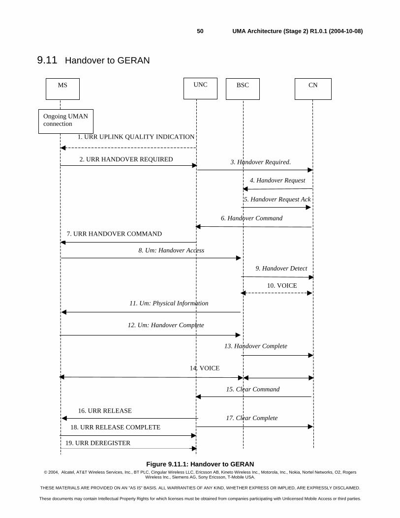
© 2004, Alcatel, AT&T Wireless Services, Inc., BT PLC, Cingular Wireless LLC, Ericsson AB, Kineto Wireless Inc., Motorola, Inc., Nokia, Nortel Networks, O2, Rogers Wireless Inc., Siemens AG, Sony Ericsson, T-Mobile USA.
THESE MATERIALS ARE PROVIDED ON AN "AS IS" BASIS. ALL WARRANTIES OF ANY KIND, WHETHER EXPRESS OR IMPLIED, ARE EXPRESSLY DISCLAIMED.
These documents may contain Intellectual Property Rights for which licenses must be obtained from companies participating with Unlicensed Mobile Access or third parties.
UMA Architecture (Stage 2) R1.0.1 (2004-10-08)50
9.11 Handover to GERAN
Figure 9.11.1: Handover to GERAN
13. Handover Complete
5. Handover Request Ack
3. Handover Required.
BSC UNC MS CN
1. URR UPLINK QUALITY INDICATION
4. Handover Request
6. Handover Command
7. URR HANDOVER COMMAND
8. Um: Handover Access
11. Um: Physical Information
16. URR RELEASE
12. Um: Handover Complete
18. URR RELEASE COMPLETE
19. URR DEREGISTER
9. Handover Detect
14. VOICE
Ongoing UMAN connection
15. Clear Command
2. URR HANDOVER REQUIRED
10. VOICE
17. Clear Complete
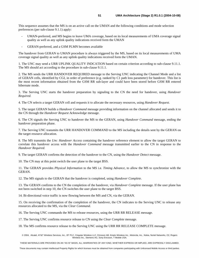
© 2004, Alcatel, AT&T Wireless Services, Inc., BT PLC, Cingular Wireless LLC, Ericsson AB, Kineto Wireless Inc., Motorola, Inc., Nokia, Nortel Networks, O2, Rogers Wireless Inc., Siemens AG, Sony Ericsson, T-Mobile USA.
THESE MATERIALS ARE PROVIDED ON AN "AS IS" BASIS. ALL WARRANTIES OF ANY KIND, WHETHER EXPRESS OR IMPLIED, ARE EXPRESSLY DISCLAIMED.
These documents may contain Intellectual Property Rights for which licenses must be obtained from companies participating with Unlicensed Mobile Access or third parties.
UMA Architecture (Stage 2) R1.0.1 (2004-10-08)51
This sequence assumes that the MS is on an active call on the UMAN and the following conditions and mode selection preferences (per sub-clause 9.1.1) apply:
- UMAN-preferred, and MS begins to leave UMA coverage, based on its local measurements of UMA coverage signal quality as well as any uplink quality indications received form the UMAN
- GERAN-preferred, and a GSM PLMN becomes available
The handover from GERAN to UMAN procedure is always triggered by the MS, based on its local measurements of UMA coverage signal quality as well as any uplink quality indications received form the UMAN.
1. The UNC may send a URR UPLINK QUALITY INDCATION based on certain criterion according to sub-clause 9.11.1. The MS should act according to the procedure in sub-clause 9.11.1.
2. The MS sends the URR HANDOVER REQUIRED message to the Serving UNC indicating the Channel Mode and a list of GERAN cells, identified by CGI, in order of preference (e.g. ranked by C1 path loss parameter) for handover. This list is the most recent information obtained from the GSM RR sub-layer and could have been stored before GSM RR entered hibernate mode.
3. The Serving UNC starts the handover preparation by signaling to the CN the need for handover, using Handover Required.
4. The CN selects a target GERAN cell and requests it to allocate the necessary resources, using Handover Request.
5. The target GERAN builds a Handover Command message providing information on the channel allocated and sends it to the CN through the Handover Request Acknowledge message.
6. The CN signals the Serving UNC to handover the MS to the GERAN, using Handover Command message, ending the handover preparation phase.
7. The Serving UNC transmits the URR HANDOVER COMMAND to the MS including the details sent by the GERAN on the target resource allocation.
8. The MS transmits the Um: Handover Access containing the handover reference element to allow the target GERAN to correlate this handover access with the Handover Command message transmitted earlier to the CN in response to the Handover Required.
9. The target GERAN confirms the detection of the handover to the CN, using the Handover Detect message.
10. The CN may at this point switch the user plane to the target BSS.
11. The GERAN provides Physical Information to the MS i.e. Timing Advance, to allow the MS to synchronize with the GERAN.
12. The MS signals to the GERAN that the handover is completed, using Handover Complete.
13. The GERAN confirms to the CN the completion of the handover, via Handover Complete message. If the user plane has not been switched in step 10, the CN switches the user plane to the target BSS.
14. Bi-directional voice traffic is now flowing between the MS and CN, via the GERAN.
15. On receiving the confirmation of the completion of the handover, the CN indicates to the Serving UNC to release any resources allocated to the MS, via the Clear Command.
16. The Serving UNC commands the MS to release resources, using the URR RR RELEASE message.
17. The Serving UNC confirms resource release to CN using the Clear Complete message.
18. The MS confirms resource release to the Serving UNC using the URR RR RELEASE COMPLETE message.
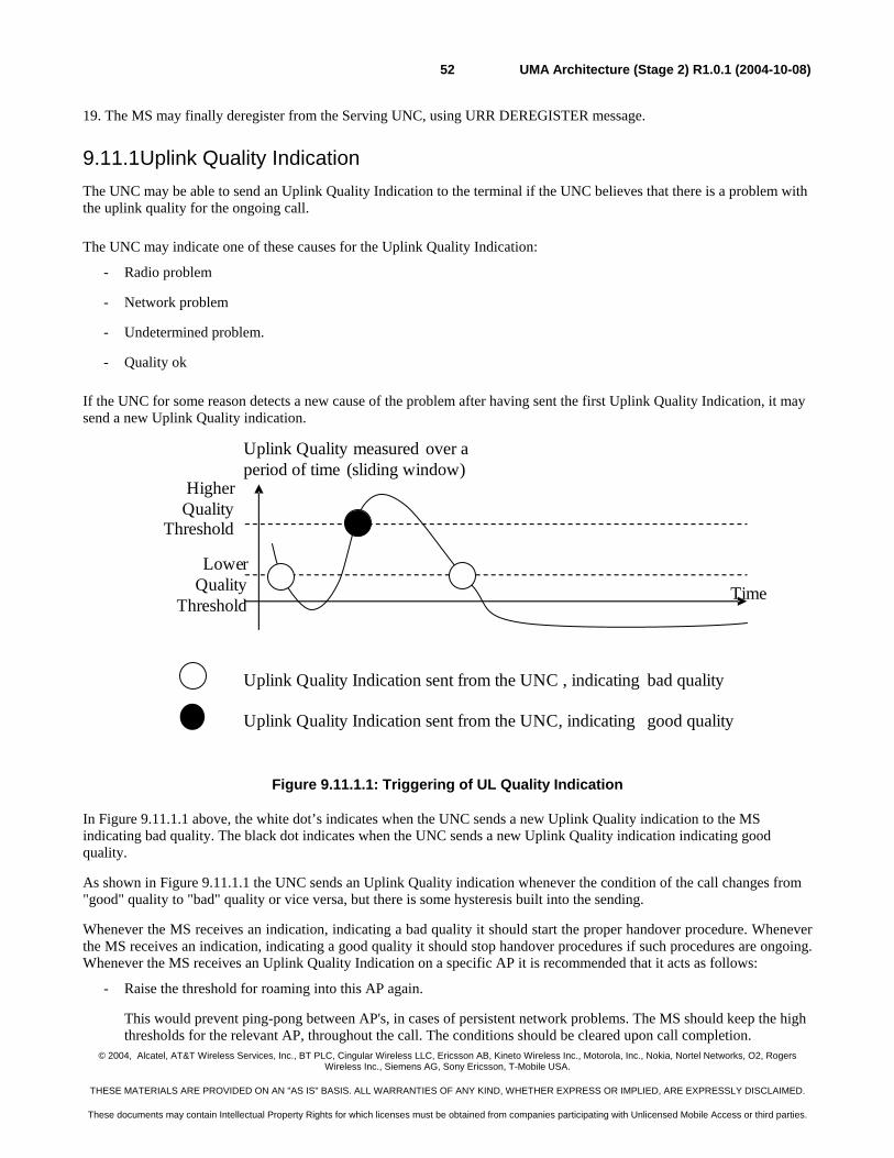
© 2004, Alcatel, AT&T Wireless Services, Inc., BT PLC, Cingular Wireless LLC, Ericsson AB, Kineto Wireless Inc., Motorola, Inc., Nokia, Nortel Networks, O2, Rogers Wireless Inc., Siemens AG, Sony Ericsson, T-Mobile USA.
THESE MATERIALS ARE PROVIDED ON AN "AS IS" BASIS. ALL WARRANTIES OF ANY KIND, WHETHER EXPRESS OR IMPLIED, ARE EXPRESSLY DISCLAIMED.
These documents may contain Intellectual Property Rights for which licenses must be obtained from companies participating with Unlicensed Mobile Access or third parties.
UMA Architecture (Stage 2) R1.0.1 (2004-10-08)52
19. The MS may finally deregister from the Serving UNC, using URR DEREGISTER message.
9.11.1 Uplink Quality Indication The UNC may be able to send an Uplink Quality Indication to the terminal if the UNC believes that there is a problem with the uplink quality for the ongoing call.
The UNC may indicate one of these causes for the Uplink Quality Indication:
- Radio problem
- Network problem
- Undetermined problem.
- Quality ok
If the UNC for some reason detects a new cause of the problem after having sent the first Uplink Quality Indication, it may send a new Uplink Quality indication.
LowerQuality
Threshold
Uplink Quality measured over aperiod of time (sliding window)
Time
Uplink Quality Indication sent from the UNC , indicating bad quality
Uplink Quality Indication sent from the UNC, indicating good quality
HigherQuality
Threshold
Figure 9.11.1.1: Triggering of UL Quality Indication
In Figure 9.11.1.1 above, the white dot’s indicates when the UNC sends a new Uplink Quality indication to the MS indicating bad quality. The black dot indicates when the UNC sends a new Uplink Quality indication indicating good quality.
As shown in Figure 9.11.1.1 the UNC sends an Uplink Quality indication whenever the condition of the call changes from "good" quality to "bad" quality or vice versa, but there is some hysteresis built into the sending.
Whenever the MS receives an indication, indicating a bad quality it should start the proper handover procedure. Whenever the MS receives an indication, indicating a good quality it should stop handover procedures if such procedures are ongoing. Whenever the MS receives an Uplink Quality Indication on a specific AP it is recommended that it acts as follows:
- Raise the threshold for roaming into this AP again.
This would prevent ping-pong between AP's, in cases of persistent network problems. The MS should keep the high thresholds for the relevant AP, throughout the call. The conditions should be cleared upon call completion.
© 2004, Alcatel, AT&T Wireless Services, Inc., BT PLC, Cingular Wireless LLC, Ericsson AB, Kineto Wireless Inc., Motorola, Inc., Nokia, Nortel Networks, O2, Rogers Wireless Inc., Siemens AG, Sony Ericsson, T-Mobile USA.
THESE MATERIALS ARE PROVIDED ON AN "AS IS" BASIS. ALL WARRANTIES OF ANY KIND, WHETHER EXPRESS OR IMPLIED, ARE EXPRESSLY DISCLAIMED.
These documents may contain Intellectual Property Rights for which licenses must be obtained from companies participating with Unlicensed Mobile Access or third parties.
UMA Architecture (Stage 2) R1.0.1 (2004-10-08)53
- Lower the threshold it applies for triggering handover/roaming out from the specific AP.
When the MS receives the Uplink Quality indication with cause “radio problem” it should measure the downlink radio quality and set the threshold for triggering handover/roaming to this new measured value.
9.12 URLC Transport Channel Management Procedures
The URLC Transport Channel management procedures are the basic URLC procedures specified to facilitate the control of the URLC connection for the user data transfer. UDP based URLC connection between the MS and the UNC for GPRS data transfer is referred to as the URLC Transport Channel. The term URLC Transport Channel is defined as following:
- The MS knows the destination IP address and destination UDP port to be used for GPRS related data. Furthermore, the MS knows the value of the URLC-CHANNEL-TIMER.
- The UNC knows the destination UDP port to be used for GPRS data transfer for a specific MS.
- The MS or UNC will activate a URLC Transport Channel only when needed; i.e. when the GPRS user data transfer is initiated.
The URLC can be in two different states, URLC-STANDBY or URLC-ACTIVE state. The state of the URLC and the corresponding transport channel are always synchronized.
In URLC-STANDBY state
- the MS is not able to send or receive GPRS data to and from the UNC. The UNC or the MS needs to activate the URLC Transport Channel before sending any GPRS data.
- the corresponding URLC Transport Channel does not exist. When the URLC Transport Channel is activated, the MS enters the URLC-ACTIVE state.
In URLC-ACTIVE state
- the MS is able to send and receive GPRS data to and from the UNC. Furthermore there exists the corresponding URLC Transport Channel for this MS.
A URLC channel timer is also defined to control the transition from URLC-ACTIVE to URLC-STANDBY state as follows:
- The MS URLC layer implements a timer that is started when the MS enters URLC-ACTIVE state and restarted each time a non-NULL LLC-PDU is transmitted to or received from the network. When the timer expires, the MS deactivates the URLC Transport Channel and the MS URLC enters URLC-STANDBY state.
The URLC channel timer value is returned to the MS as part of the UMA Registration procedure (i.e. in URR REGISTER ACCEPT message).
9.12.1 Activation of URLC Transport Channel by the MS The following message sequence depicts the MS initiated URLC Transport Channel activation procedure. The basic idea behind this sequence is that the UNC and MS can dynamically negotiate the IP address and UDP port numbers for data transfer. This procedure can facilitate the UNC load balancing; moreover, it allows the UNC to optimize the processing and maintain the context for active users only.
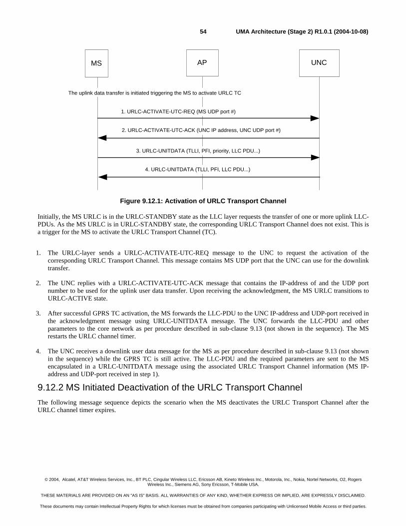
© 2004, Alcatel, AT&T Wireless Services, Inc., BT PLC, Cingular Wireless LLC, Ericsson AB, Kineto Wireless Inc., Motorola, Inc., Nokia, Nortel Networks, O2, Rogers Wireless Inc., Siemens AG, Sony Ericsson, T-Mobile USA.
THESE MATERIALS ARE PROVIDED ON AN "AS IS" BASIS. ALL WARRANTIES OF ANY KIND, WHETHER EXPRESS OR IMPLIED, ARE EXPRESSLY DISCLAIMED.
These documents may contain Intellectual Property Rights for which licenses must be obtained from companies participating with Unlicensed Mobile Access or third parties.
UMA Architecture (Stage 2) R1.0.1 (2004-10-08)54
Figure 9.12.1: Activation of URLC Transport Channel
Initially, the MS URLC is in the URLC-STANDBY state as the LLC layer requests the transfer of one or more uplink LLC-PDUs. As the MS URLC is in URLC-STANDBY state, the corresponding URLC Transport Channel does not exist. This is a trigger for the MS to activate the URLC Transport Channel (TC).
1. The URLC-layer sends a URLC-ACTIVATE-UTC-REQ message to the UNC to request the activation of the corresponding URLC Transport Channel. This message contains MS UDP port that the UNC can use for the downlink transfer.
2. The UNC replies with a URLC-ACTIVATE-UTC-ACK message that contains the IP-address of and the UDP port number to be used for the uplink user data transfer. Upon receiving the acknowledgment, the MS URLC transitions to URLC-ACTIVE state.
3. After successful GPRS TC activation, the MS forwards the LLC-PDU to the UNC IP-address and UDP-port received in the acknowledgment message using URLC-UNITDATA message. The UNC forwards the LLC-PDU and other parameters to the core network as per procedure described in sub-clause 9.13 (not shown in the sequence). The MS restarts the URLC channel timer.
4. The UNC receives a downlink user data message for the MS as per procedure described in sub-clause 9.13 (not shown in the sequence) while the GPRS TC is still active. The LLC-PDU and the required parameters are sent to the MS encapsulated in a URLC-UNITDATA message using the associated URLC Transport Channel information (MS IP-address and UDP-port received in step 1).
9.12.2 MS Initiated Deactivation of the URLC Transport Channel The following message sequence depicts the scenario when the MS deactivates the URLC Transport Channel after the URLC channel timer expires.
UNCMS AP
1. URLC-ACTIVATE-UTC-REQ (MS UDP port #)
The uplink data transfer is initiated triggering the MS to activate URLC TC
2. URLC-ACTIVATE-UTC-ACK (UNC IP address, UNC UDP port #)
3. URLC-UNITDATA (TLLI, PFI, priority, LLC PDU...)
4. URLC-UNITDATA (TLLI, PFI, LLC PDU...)
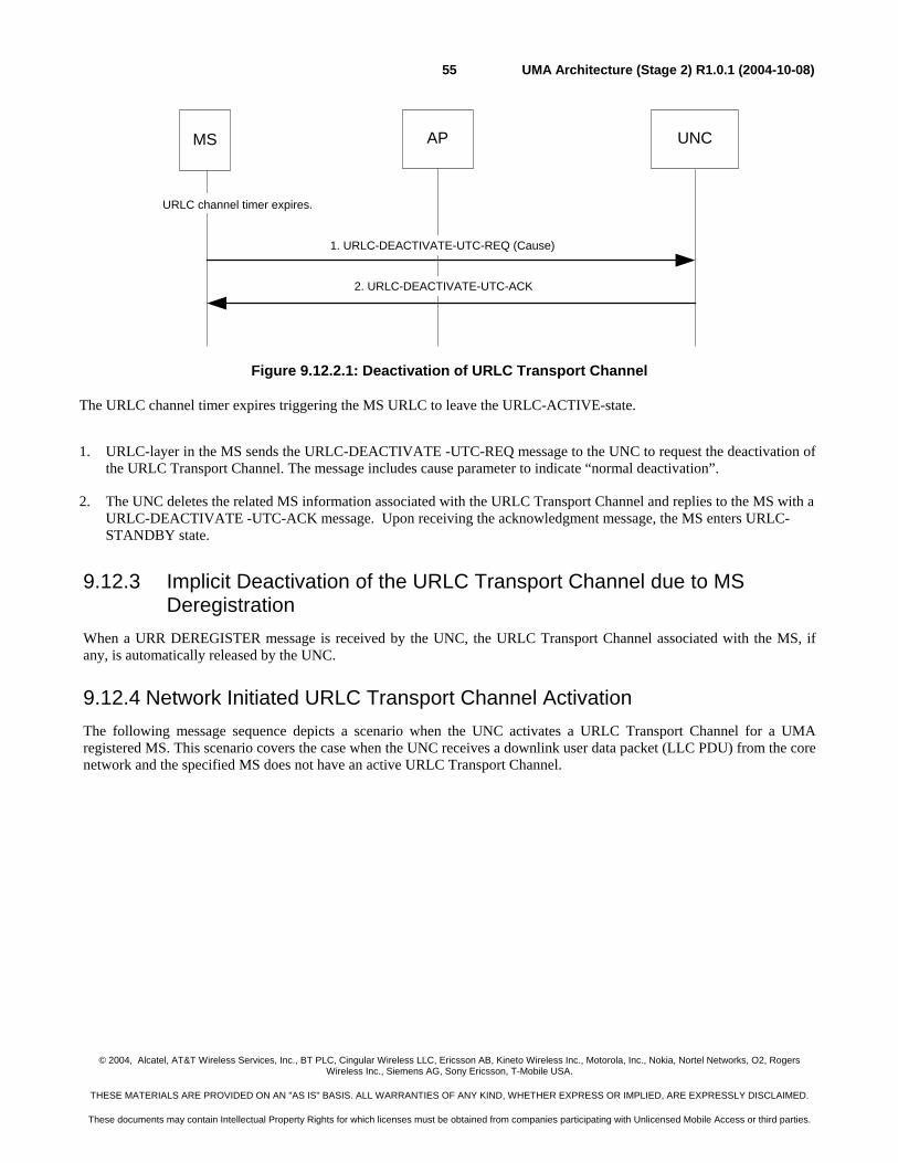
© 2004, Alcatel, AT&T Wireless Services, Inc., BT PLC, Cingular Wireless LLC, Ericsson AB, Kineto Wireless Inc., Motorola, Inc., Nokia, Nortel Networks, O2, Rogers Wireless Inc., Siemens AG, Sony Ericsson, T-Mobile USA.
THESE MATERIALS ARE PROVIDED ON AN "AS IS" BASIS. ALL WARRANTIES OF ANY KIND, WHETHER EXPRESS OR IMPLIED, ARE EXPRESSLY DISCLAIMED.
These documents may contain Intellectual Property Rights for which licenses must be obtained from companies participating with Unlicensed Mobile Access or third parties.
UMA Architecture (Stage 2) R1.0.1 (2004-10-08)55
Figure 9.12.2.1: Deactivation of URLC Transport Channel
The URLC channel timer expires triggering the MS URLC to leave the URLC-ACTIVE-state.
1. URLC-layer in the MS sends the URLC-DEACTIVATE -UTC-REQ message to the UNC to request the deactivation of the URLC Transport Channel. The message includes cause parameter to indicate “normal deactivation”.
2. The UNC deletes the related MS information associated with the URLC Transport Channel and replies to the MS with a URLC-DEACTIVATE -UTC-ACK message. Upon receiving the acknowledgment message, the MS enters URLC-STANDBY state.
9.12.3 Implicit Deactivation of the URLC Transport Channel due to MS Deregistration
When a URR DEREGISTER message is received by the UNC, the URLC Transport Channel associated with the MS, if any, is automatically released by the UNC.
9.12.4 Network Initiated URLC Transport Channel Activation The following message sequence depicts a scenario when the UNC activates a URLC Transport Channel for a UMA registered MS. This scenario covers the case when the UNC receives a downlink user data packet (LLC PDU) from the core network and the specified MS does not have an active URLC Transport Channel.
UNC MS AP
1. URLC-DEACTIVATE-UTC-REQ (Cause)
URLC channel timer expires.
2. URLC-DEACTIVATE-UTC-ACK
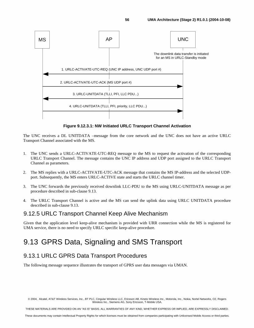
© 2004, Alcatel, AT&T Wireless Services, Inc., BT PLC, Cingular Wireless LLC, Ericsson AB, Kineto Wireless Inc., Motorola, Inc., Nokia, Nortel Networks, O2, Rogers Wireless Inc., Siemens AG, Sony Ericsson, T-Mobile USA.
THESE MATERIALS ARE PROVIDED ON AN "AS IS" BASIS. ALL WARRANTIES OF ANY KIND, WHETHER EXPRESS OR IMPLIED, ARE EXPRESSLY DISCLAIMED.
These documents may contain Intellectual Property Rights for which licenses must be obtained from companies participating with Unlicensed Mobile Access or third parties.
UMA Architecture (Stage 2) R1.0.1 (2004-10-08)56
Figure 9.12.3.1: NW Initiated URLC Transport Channel Activation
The UNC receives a DL UNITDATA –message from the core network and the UNC does not have an active URLC Transport Channel associated with the MS.
1. The UNC sends a URLC-ACTIVATE-UTC-REQ message to the MS to request the activation of the corresponding URLC Transport Channel. The message contains the UNC IP address and UDP port assigned to the URLC Transport Channel as parameters.
2. The MS replies with a URLC-ACTIVATE-UTC-ACK message that contains the MS IP-address and the selected UDP-port. Subsequently, the MS enters URLC-ACTIVE state and starts the URLC channel timer.
3. The UNC forwards the previously received downlink LLC-PDU to the MS using URLC-UNITDATA message as per procedure described in sub-clause 9.13.
4. The URLC Transport Channel is active and the MS can send the uplink data using URLC UNITDATA procedure described in sub-clause 9.13.
9.12.5 URLC Transport Channel Keep Alive Mechanism Given that the application level keep-alive mechanism is provided with URR connection while the MS is registered for UMA service, there is no need to specify URLC specific keep-alive procedure.
9.13 GPRS Data, Signaling and SMS Transport
9.13.1 URLC GPRS Data Transport Procedures The following message sequence illustrates the transport of GPRS user data messages via UMAN.
UNCMS AP
2. URLC-ACTIVATE-UTC-ACK (MS UDP port #)
The downlink data transfer is initiatedfor an MS in URLC-Standby mode
1. URLC-ACTIVATE-UTC-REQ (UNC IP address, UNC UDP port #)
4. URLC-UNITDATA (TLLI, PFI, priority, LLC PDU...)
3. URLC-UNITDATA (TLLI, PFI, LLC PDU...)
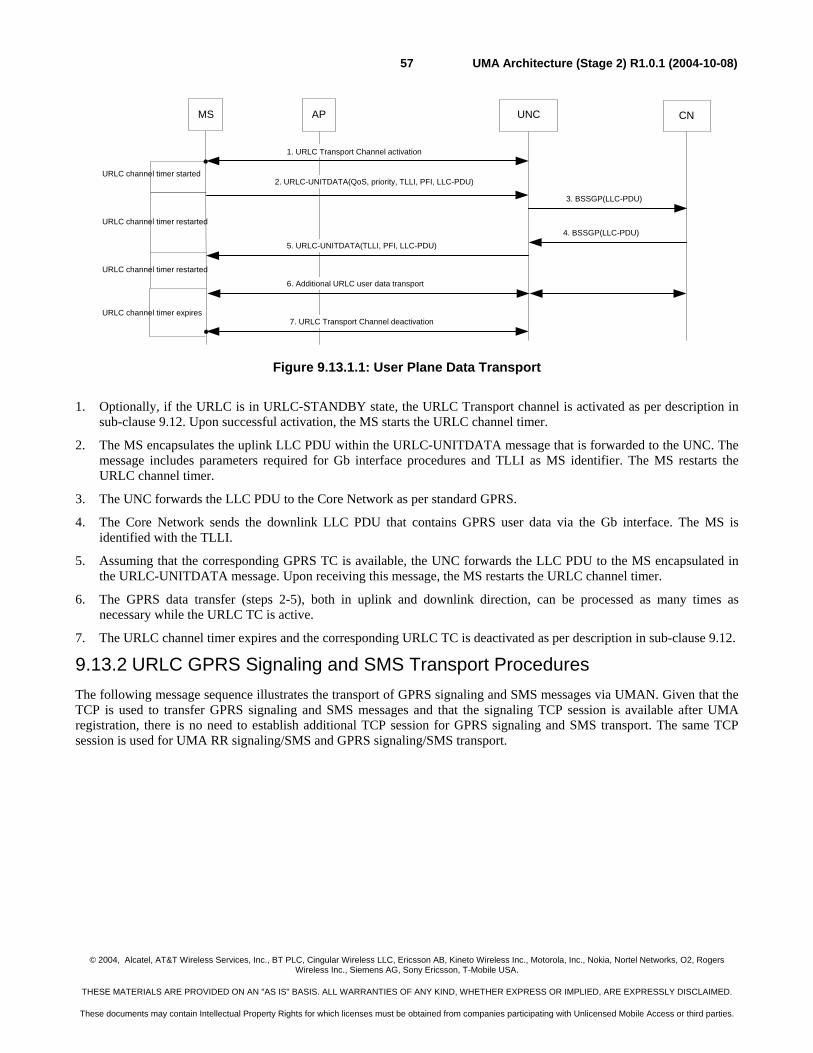
© 2004, Alcatel, AT&T Wireless Services, Inc., BT PLC, Cingular Wireless LLC, Ericsson AB, Kineto Wireless Inc., Motorola, Inc., Nokia, Nortel Networks, O2, Rogers Wireless Inc., Siemens AG, Sony Ericsson, T-Mobile USA.
THESE MATERIALS ARE PROVIDED ON AN "AS IS" BASIS. ALL WARRANTIES OF ANY KIND, WHETHER EXPRESS OR IMPLIED, ARE EXPRESSLY DISCLAIMED.
These documents may contain Intellectual Property Rights for which licenses must be obtained from companies participating with Unlicensed Mobile Access or third parties.
UMA Architecture (Stage 2) R1.0.1 (2004-10-08)57
Figure 9.13.1.1: User Plane Data Transport
1. Optionally, if the URLC is in URLC-STANDBY state, the URLC Transport channel is activated as per description in sub-clause 9.12. Upon successful activation, the MS starts the URLC channel timer.
2. The MS encapsulates the uplink LLC PDU within the URLC-UNITDATA message that is forwarded to the UNC. The message includes parameters required for Gb interface procedures and TLLI as MS identifier. The MS restarts the URLC channel timer.
3. The UNC forwards the LLC PDU to the Core Network as per standard GPRS.
4. The Core Network sends the downlink LLC PDU that contains GPRS user data via the Gb interface. The MS is identified with the TLLI.
5. Assuming that the corresponding GPRS TC is available, the UNC forwards the LLC PDU to the MS encapsulated in the URLC-UNITDATA message. Upon receiving this message, the MS restarts the URLC channel timer.
6. The GPRS data transfer (steps 2-5), both in uplink and downlink direction, can be processed as many times as necessary while the URLC TC is active.
7. The URLC channel timer expires and the corresponding URLC TC is deactivated as per description in sub-clause 9.12.
9.13.2 URLC GPRS Signaling and SMS Transport Procedures The following message sequence illustrates the transport of GPRS signaling and SMS messages via UMAN. Given that the TCP is used to transfer GPRS signaling and SMS messages and that the signaling TCP session is available after UMA registration, there is no need to establish additional TCP session for GPRS signaling and SMS transport. The same TCP session is used for UMA RR signaling/SMS and GPRS signaling/SMS transport.
UNCMS CN
3. BSSGP(LLC-PDU)
2. URLC-UNITDATA(QoS, priority, TLLI, PFI, LLC-PDU)
4. BSSGP(LLC-PDU)
1. URLC Transport Channel activation
7. URLC Transport Channel deactivation
URLC channel timer started
5. URLC-UNITDATA(TLLI, PFI, LLC-PDU)
6. Additional URLC user data transport
AP
URLC channel timer restarted
URLC channel timer restarted
URLC channel timer expires
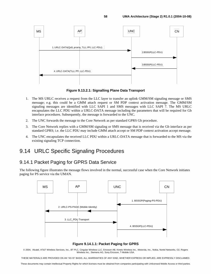
© 2004, Alcatel, AT&T Wireless Services, Inc., BT PLC, Cingular Wireless LLC, Ericsson AB, Kineto Wireless Inc., Motorola, Inc., Nokia, Nortel Networks, O2, Rogers Wireless Inc., Siemens AG, Sony Ericsson, T-Mobile USA.
THESE MATERIALS ARE PROVIDED ON AN "AS IS" BASIS. ALL WARRANTIES OF ANY KIND, WHETHER EXPRESS OR IMPLIED, ARE EXPRESSLY DISCLAIMED.
These documents may contain Intellectual Property Rights for which licenses must be obtained from companies participating with Unlicensed Mobile Access or third parties.
UMA Architecture (Stage 2) R1.0.1 (2004-10-08)58
UNCMS CN
2.BSSGP(LLC-PDU)
3.BSSGP(LLC-PDU)
AP
1. URLC-DATA(QoS, priority, TLLI, PFI, LLC-PDU)
4. URLC-DATA(TLLI, PFI, LLC-PDU)
Figure 9.13.2.1: Signalling Plane Data Transport
1. The MS URLC receives a request from the LLC layer to transfer an uplink GMM/SM signaling message or SMS message; e.g. this could be a GMM attach request or SM PDP context activation message. The GMM/SM signaling messages are identified with LLC SAPI 1 and SMS messages with LLC SAPI 7. The MS URLC encapsulates the LLC PDU within a URLC-DATA message including the parameters that will be required for Gb interface procedures. Subsequently, the message is forwarded to the UNC.
2. The UNC forwards the message to the Core Network as per standard GPRS Gb procedure.
3. The Core Network replies with a GMM/SM signaling or SMS message that is received via the Gb interface as per standard GPRS; i.e. the LLC PDU may include GMM attach accept or SM PDP context activation accept message.
4. The UNC encapsulates the received LLC PDU within a URLC-DATA message that is forwarded to the MS via the existing signaling TCP connection.
9.14 URLC Specific Signaling Procedures
9.14.1 Packet Paging for GPRS Data Service The following figure illustrates the message flows involved in the normal, successful case when the Core Network initiates paging for PS service via the UMAN.
Figure 9.14.1.1: Packet Paging for GPRS
UNCMS CN
4. BSSGP(LLC-PDU)
1. BSSGP(Paging-PS-PDU)
2. URLC-PS-PAGE (Mobile Identity)
3. LLC_PDU Transport
AP
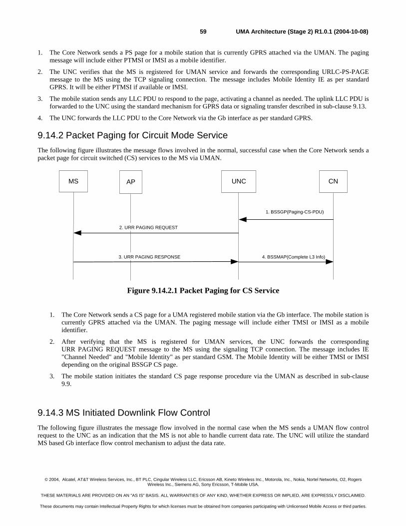
© 2004, Alcatel, AT&T Wireless Services, Inc., BT PLC, Cingular Wireless LLC, Ericsson AB, Kineto Wireless Inc., Motorola, Inc., Nokia, Nortel Networks, O2, Rogers Wireless Inc., Siemens AG, Sony Ericsson, T-Mobile USA.
THESE MATERIALS ARE PROVIDED ON AN "AS IS" BASIS. ALL WARRANTIES OF ANY KIND, WHETHER EXPRESS OR IMPLIED, ARE EXPRESSLY DISCLAIMED.
These documents may contain Intellectual Property Rights for which licenses must be obtained from companies participating with Unlicensed Mobile Access or third parties.
UMA Architecture (Stage 2) R1.0.1 (2004-10-08)59
1. The Core Network sends a PS page for a mobile station that is currently GPRS attached via the UMAN. The paging message will include either PTMSI or IMSI as a mobile identifier.
2. The UNC verifies that the MS is registered for UMAN service and forwards the corresponding URLC-PS-PAGE message to the MS using the TCP signaling connection. The message includes Mobile Identity IE as per standard GPRS. It will be either PTMSI if available or IMSI.
3. The mobile station sends any LLC PDU to respond to the page, activating a channel as needed. The uplink LLC PDU is forwarded to the UNC using the standard mechanism for GPRS data or signaling transfer described in sub-clause 9.13.
4. The UNC forwards the LLC PDU to the Core Network via the Gb interface as per standard GPRS.
9.14.2 Packet Paging for Circuit Mode Service The following figure illustrates the message flows involved in the normal, successful case when the Core Network sends a packet page for circuit switched (CS) services to the MS via UMAN.
Figure 9.14.2.1 Packet Paging for CS Service
1. The Core Network sends a CS page for a UMA registered mobile station via the Gb interface. The mobile station is currently GPRS attached via the UMAN. The paging message will include either TMSI or IMSI as a mobile identifier.
2. After verifying that the MS is registered for UMAN services, the UNC forwards the corresponding URR PAGING REQUEST message to the MS using the signaling TCP connection. The message includes IE "Channel Needed" and "Mobile Identity" as per standard GSM. The Mobile Identity will be either TMSI or IMSI depending on the original BSSGP CS page.
3. The mobile station initiates the standard CS page response procedure via the UMAN as described in sub-clause 9.9.
9.14.3 MS Initiated Downlink Flow Control The following figure illustrates the message flow involved in the normal case when the MS sends a UMAN flow control request to the UNC as an indication that the MS is not able to handle current data rate. The UNC will utilize the standard MS based Gb interface flow control mechanism to adjust the data rate.
UNCMS CN
1. BSSGP(Paging-CS-PDU)
2. URR PAGING REQUEST
3. URR PAGING RESPONSE
AP
4. BSSMAP(Complete L3 Info)
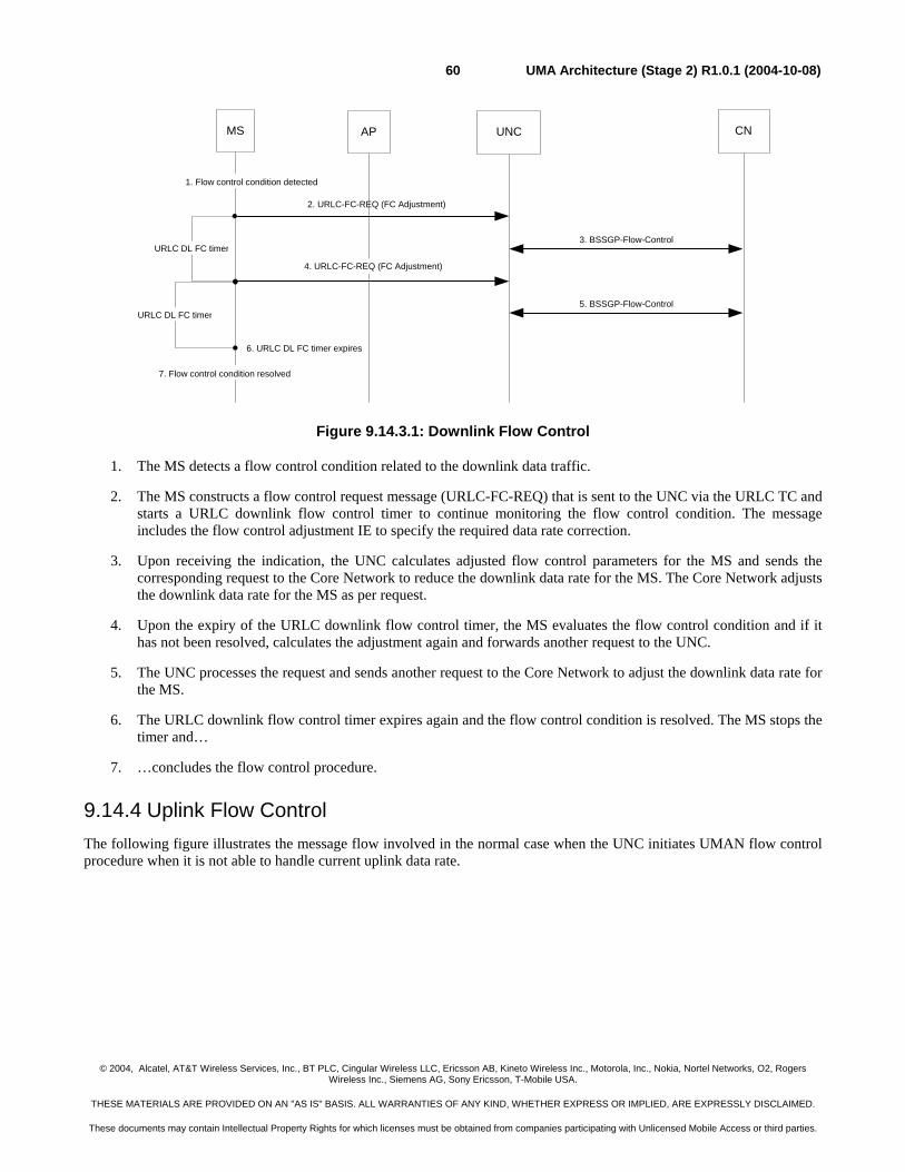
© 2004, Alcatel, AT&T Wireless Services, Inc., BT PLC, Cingular Wireless LLC, Ericsson AB, Kineto Wireless Inc., Motorola, Inc., Nokia, Nortel Networks, O2, Rogers Wireless Inc., Siemens AG, Sony Ericsson, T-Mobile USA.
THESE MATERIALS ARE PROVIDED ON AN "AS IS" BASIS. ALL WARRANTIES OF ANY KIND, WHETHER EXPRESS OR IMPLIED, ARE EXPRESSLY DISCLAIMED.
These documents may contain Intellectual Property Rights for which licenses must be obtained from companies participating with Unlicensed Mobile Access or third parties.
UMA Architecture (Stage 2) R1.0.1 (2004-10-08)60
Figure 9.14.3.1: Downlink Flow Control
1. The MS detects a flow control condition related to the downlink data traffic.
2. The MS constructs a flow control request message (URLC-FC-REQ) that is sent to the UNC via the URLC TC and starts a URLC downlink flow control timer to continue monitoring the flow control condition. The message includes the flow control adjustment IE to specify the required data rate correction.
3. Upon receiving the indication, the UNC calculates adjusted flow control parameters for the MS and sends the corresponding request to the Core Network to reduce the downlink data rate for the MS. The Core Network adjusts the downlink data rate for the MS as per request.
4. Upon the expiry of the URLC downlink flow control timer, the MS evaluates the flow control condition and if it has not been resolved, calculates the adjustment again and forwards another request to the UNC.
5. The UNC processes the request and sends another request to the Core Network to adjust the downlink data rate for the MS.
6. The URLC downlink flow control timer expires again and the flow control condition is resolved. The MS stops the timer and…
7. …concludes the flow control procedure.
9.14.4 Uplink Flow Control The following figure illustrates the message flow involved in the normal case when the UNC initiates UMAN flow control procedure when it is not able to handle current uplink data rate.
UNCMS CN
2. URLC-FC-REQ (FC Adjustment)
1. Flow control condition detected
3. BSSGP-Flow-ControlURLC DL FC timer
7. Flow control condition resolved
URLC DL FC timer5. BSSGP-Flow-Control
AP
4. URLC-FC-REQ (FC Adjustment)
6. URLC DL FC timer expires
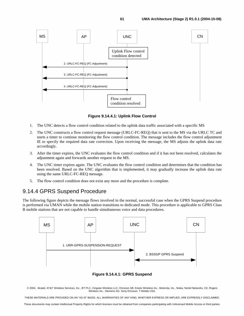
© 2004, Alcatel, AT&T Wireless Services, Inc., BT PLC, Cingular Wireless LLC, Ericsson AB, Kineto Wireless Inc., Motorola, Inc., Nokia, Nortel Networks, O2, Rogers Wireless Inc., Siemens AG, Sony Ericsson, T-Mobile USA.
THESE MATERIALS ARE PROVIDED ON AN "AS IS" BASIS. ALL WARRANTIES OF ANY KIND, WHETHER EXPRESS OR IMPLIED, ARE EXPRESSLY DISCLAIMED.
These documents may contain Intellectual Property Rights for which licenses must be obtained from companies participating with Unlicensed Mobile Access or third parties.
UMA Architecture (Stage 2) R1.0.1 (2004-10-08)61
Figure 9.14.4.1: Uplink Flow Control
1. The UNC detects a flow control condition related to the uplink data traffic associated with a specific MS
2. The UNC constructs a flow control request message (URLC-FC-REQ) that is sent to the MS via the URLC TC and starts a timer to continue monitoring the flow control condition. The message includes the flow control adjustment IE to specify the required data rate correction. Upon receiving the message, the MS adjusts the uplink data rate accordingly.
3. After the timer expires, the UNC evaluates the flow control condition and if it has not been resolved, calculates the adjustment again and forwards another request to the MS.
4. The UNC timer expires again. The UNC evaluates the flow control condition and determines that the condition has been resolved. Based on the UNC algorithm that is implemented, it may gradually increase the uplink data rate using the same URLC-FC-REQ message.
5. The flow control condition does not exist any more and the procedure is complete.
9.14.4 GPRS Suspend Procedure The following figure depicts the message flows involved in the normal, successful case when the GPRS Suspend procedure is performed via UMAN while the mobile station transitions to dedicated mode. This procedure is applicable to GPRS Class B mobile stations that are not capable to handle simultaneous voice and data procedures.
Figure 9.14.4.1: GPRS Suspend
UNCMS CN
2. BSSGP GPRS Suspend
1. URR-GPRS-SUSPENSION-REQUEST
AP
UNCMS CNAP
3. URLC-FC-REQ (FC Adjustment)
2. URLC-FC-REQ (FC Adjustment)
4. URLC-FC-REQ (FC Adjustment)
Uplink Flow control condition detected
Flow control condition resolved
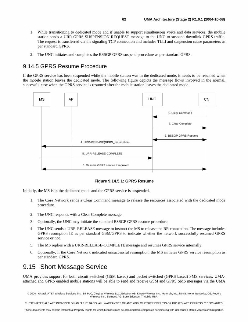
© 2004, Alcatel, AT&T Wireless Services, Inc., BT PLC, Cingular Wireless LLC, Ericsson AB, Kineto Wireless Inc., Motorola, Inc., Nokia, Nortel Networks, O2, Rogers Wireless Inc., Siemens AG, Sony Ericsson, T-Mobile USA.
THESE MATERIALS ARE PROVIDED ON AN "AS IS" BASIS. ALL WARRANTIES OF ANY KIND, WHETHER EXPRESS OR IMPLIED, ARE EXPRESSLY DISCLAIMED.
These documents may contain Intellectual Property Rights for which licenses must be obtained from companies participating with Unlicensed Mobile Access or third parties.
UMA Architecture (Stage 2) R1.0.1 (2004-10-08)62
1. While transitioning to dedicated mode and if unable to support simultaneous voice and data services, the mobile station sends a URR-GPRS-SUSPENSION-REQUEST message to the UNC to suspend downlink GPRS traffic. The request is transferred via the signaling TCP connection and includes TLLI and suspension cause parameters as per standard GPRS.
2. The UNC initiates and completes the BSSGP GPRS suspend procedure as per standard GPRS.
9.14.5 GPRS Resume Procedure If the GPRS service has been suspended while the mobile station was in the dedicated mode, it needs to be resumed when the mobile station leaves the dedicated mode. The following figure depicts the message flows involved in the normal, successful case when the GPRS service is resumed after the mobile station leaves the dedicated mode.
Figure 9.14.5.1: GPRS Resume
Initially, the MS is in the dedicated mode and the GPRS service is suspended.
1. The Core Network sends a Clear Command message to release the resources associated with the dedicated mode procedure.
2. The UNC responds with a Clear Complete message.
3. Optionally, the UNC may initiate the standard BSSGP GPRS resume procedure.
4. The UNC sends a URR-RELEASE message to instruct the MS to release the RR connection. The message includes GPRS resumption IE as per standard GSM/GPRS to indicate whether the network successfully resumed GPRS service or not.
5. The MS replies with a URR-RELEASE-COMPLETE message and resumes GPRS service internally.
6. Optionally, if the Core Network indicated unsuccessful resumption, the MS initiates GPRS service resumption as per standard GPRS.
9.15 Short Message Service UMA provides support for both circuit switched (GSM based) and packet switched (GPRS based) SMS services. UMA-attached and GPRS enabled mobile stations will be able to send and receive GSM and GPRS SMS messages via the UMA
UNCMS CN
4. URR-RELEASE(GPRS_resumption)
6. Resume GPRS service if required
5. URR-RELEASE-COMPLETE
AP
1. Clear Command
2. Clear Complete
3. BSSGP GPRS Resume
© 2004, Alcatel, AT&T Wireless Services, Inc., BT PLC, Cingular Wireless LLC, Ericsson AB, Kineto Wireless Inc., Motorola, Inc., Nokia, Nortel Networks, O2, Rogers Wireless Inc., Siemens AG, Sony Ericsson, T-Mobile USA.
THESE MATERIALS ARE PROVIDED ON AN "AS IS" BASIS. ALL WARRANTIES OF ANY KIND, WHETHER EXPRESS OR IMPLIED, ARE EXPRESSLY DISCLAIMED.
These documents may contain Intellectual Property Rights for which licenses must be obtained from companies participating with Unlicensed Mobile Access or third parties.
UMA Architecture (Stage 2) R1.0.1 (2004-10-08)63
network, regardless of the GPRS class (B or C) with the restriction that the type C mobiles support only GPRS SMS messages.
9.15.1 GSM SMS Services The UMA GSM SMS support is based on the same mechanism that is utilized for GSM mobility management and call control. On the MS side, the SMS layers (including the supporting CM sub-layer functions) utilize the services of the MM layer to transfer SMS messages per standard circuit switched GSM implementation. The SM-CP protocol is effectively tunneled between the MS and the MSC, using UMA-RR messages to UNC which inter-works it to BSSAP messages.
As with GSM mobility management and call control procedures, the IPsec secure tunnel and TCP session is used to provide secure and reliable SMS delivery over the IP network.
9.15.2 GPRS SMS Services GPRS SMS message transfer is based on the same mechanism as the transfer of the GPRS MM/SM signaling messages. On the MS side, the SMS layers (including the supporting CM sub-layer functions) utilize the services of the LLC layer to transfer SMS messages per standard packet switched GPRS implementation.
GPRS SMS service employs the unacknowledged mode of LLC frame transfer as described in 3GPP TS 44.064, using SAPI=7 for the transfer of SMS messages. This SAPI identifies the SMS Logical Link Entity within the LLC layer. The CM-sub-layer entity retransmits the CP-DATA message if CP-DATA-ACK is not received. The SM-CP protocol is effectively tunneled between the MS and the SGSN, using UMA-RLC messages to UNC which inter-works it to LLC-PDU relay functions providing reliable SMS delivery.
As with GPRS signaling, the secure IPSec tunnel and TCP session is used to provide secure and reliable GPRS SMS delivery over the IP network.
9.16 Supplementary Services GSM has standardized a large number of supplementary services. These supplementary services involve procedures that operate end-to-end between the MS and the MSC. Beyond the basic 3GPP TS 24.008 DTAP messages used for MO and MT calls, some additional 3GPP TS 24.008 DTAP messages are used for these additional supplementary service purposes. These DTAP message are relayed between the MS and MSC in the same manner as in the other call control and mobility management scenarios described in this document.
9.17 Emergency Services When a caller dials 911, the address and phone number of the caller are displayed on a screen at the 911 service center. Enhanced 911 or E911 provides dispatchers with the location of callers and their phone number. This is also known as automatic number information (ANI) and automatic location information (ALI).
The U.S. FCC has ordered wireless service providers to address the issue in an effort to improve 911 calling from mobile phones. The U.S. FCC plan includes two phases.
9.17.1 Phase 1 Solution
9.17.1.1 Phase 1 Requirements
Wireless service providers were required by the FCC to have the capability to send wireless 911 calls to an E911 public safety answering point (PSAP) containing two important sets of data:
1. The location of the cell tower through which the E911 call was processed.
© 2004, Alcatel, AT&T Wireless Services, Inc., BT PLC, Cingular Wireless LLC, Ericsson AB, Kineto Wireless Inc., Motorola, Inc., Nokia, Nortel Networks, O2, Rogers Wireless Inc., Siemens AG, Sony Ericsson, T-Mobile USA.
THESE MATERIALS ARE PROVIDED ON AN "AS IS" BASIS. ALL WARRANTIES OF ANY KIND, WHETHER EXPRESS OR IMPLIED, ARE EXPRESSLY DISCLAIMED.
These documents may contain Intellectual Property Rights for which licenses must be obtained from companies participating with Unlicensed Mobile Access or third parties.
UMA Architecture (Stage 2) R1.0.1 (2004-10-08)64
2. The mobile directory number (MDN) or "call back number" of the wireless phone placing the 911 call.
9.17.1.2 Phase 1 Mechanism
The UNC shall indicate whether, when in UMA mode, GERAN or UMAN is preferred for support of emergency calls.
- If UMAN is the preferred emergency call mode the emergency call shall be placed over UMAN if the mobile is in UMA mode. The UNC can reject the call depending on operator policy.
- If GERAN is the preferred emergency mode the emergency call shall be placed over the GERAN when the GERAN network is available. If a GERAN network is not available the emergency call shall be placed over UMAN.
9.17.2 Phase 2 Solution
9.17.2.1 Phase 2 Requirements
Wireless service providers are required by the FCC to have the ability to send the actual caller's location to the E911 PSAP. The location accuracy requirements differ depending on whether a network-based or handset-based approach is chosen.
− Network-based requirement: Within 100 meters, 67% of the time and within 300 meters, 95% of the time
− Handset-based requirement: Within 50 meters, 67% of the time and within 150 meters, 95% of the time
The handset-based requirements apply for any solution requires new, modified or upgraded handsets.
9.17.2.2 Phase 2 Solution
The emergency call is placed over GERAN or UMAN, as defined in section 9.17.1.2. If the emergency call is placed over UMAN, the UNC will need to be provided accurate location information for the MS or the AP through which the MS is placing the emergency call. This can be done in a number of ways:
- the UNC can maintain a database of AP location records used for UMA service; the AP location is provided by the MS via URR REGISTER REQUEST /URR REGISTER UPDATE message (per sub-clause 9.2.3) or via some management interface;
- the MS can provide its current location (e.g. obtained via AGPS) in URR REGISTER/UPDATE message
- the UNC can lookup a location database based upon MS (public) IP address and/or AP MAC address
The UNC can then pass this location information through BSSMAP to the CN, when requested.
9.18 Location Services The MS shall provide the following minimum information to the UNC in order for the UNC to determine the geographic location of the MS.
1. Cell-Info: The MS shall provide the identity of the GSM cell it is camped on, in case GSM coverage is available, at the time of UMAN registration. The UNC can then determine the MS location to the resolution of a single GSM cell. This can enable location services that require location resolution no finer than that provided by a GSM cell (e.g. E911 Phase 1).
2. AP-Info: The MS shall provide the identity of the AP it is currently connecting through. Additional information may be provided to determine the AP location e.g. a street address or a latitude/longitude. The UNC can then determine the MS location to the resolution of a single AP’s coverage area. This can enable location services that require a more fine grain location resolution than that provided by a GSM cell (e.g. E911 Phase 2).
© 2004, Alcatel, AT&T Wireless Services, Inc., BT PLC, Cingular Wireless LLC, Ericsson AB, Kineto Wireless Inc., Motorola, Inc., Nokia, Nortel Networks, O2, Rogers Wireless Inc., Siemens AG, Sony Ericsson, T-Mobile USA.
THESE MATERIALS ARE PROVIDED ON AN "AS IS" BASIS. ALL WARRANTIES OF ANY KIND, WHETHER EXPRESS OR IMPLIED, ARE EXPRESSLY DISCLAIMED.
These documents may contain Intellectual Property Rights for which licenses must be obtained from companies participating with Unlicensed Mobile Access or third parties.
UMA Architecture (Stage 2) R1.0.1 (2004-10-08)65
The mechanism to provide Cell-Info and AP-Info from the MS to the UNC uses the URR-REGISTER or URR- REGISTER UPDATE messages.
The UNC may maintain an internal database of AP records that identify the AP by its MAC or BD address, and contain the AP location, such as street address and latitude/longitude. This database may be centralized for use by multiple UNCs; however this is outside the scope of this specification.
Appendix A
A.1 Minimum WLAN Specifications (Normative)
A.1.1 Bluetooth
The following are the minimum specifications for Handset Bluetooth Radio for UMA.
- Transmit Power at the antenna input (for Handset) shall be +16dBm (+4/-1 dBm).
- Receive Sensitivity (for Handset) shall be at least -81dBm.
- Antenna gain should be at least -10dBi.
The following are the minimum specifications for AP Bluetooth Radio for UMA.
- Transmit Power at the antenna input (for AP) should be +20dBm (+0/-3 dBm).
- Receive Sensitivity (for AP) should be at least -86dBm
- Antenna gain should be at least -0dBi.
A.1.2 802.11 The following are the minimum specifications for 802.11 (802.11b mode) Radio for UMA.
- Transmit Power at the antenna input (for AP and Handset) shall be +17dBm (+3/-2 dBm).
- Receive Sensitivity (for AP and Handset) shall be at least -87dBm (at 1Mbit/s)
- Handset antenna gain should be at least -10dBi.
- AP antenna gain should be at least -0dBi
Appendix B WLAN Recommendations
B.1 802.11 Note: These recommendations do not imply the use of a specific 802.11 PHY technology e.g. 802.11b, 802.11g, etc.
© 2004, Alcatel, AT&T Wireless Services, Inc., BT PLC, Cingular Wireless LLC, Ericsson AB, Kineto Wireless Inc., Motorola, Inc., Nokia, Nortel Networks, O2, Rogers Wireless Inc., Siemens AG, Sony Ericsson, T-Mobile USA.
THESE MATERIALS ARE PROVIDED ON AN "AS IS" BASIS. ALL WARRANTIES OF ANY KIND, WHETHER EXPRESS OR IMPLIED, ARE EXPRESSLY DISCLAIMED.
These documents may contain Intellectual Property Rights for which licenses must be obtained from companies participating with Unlicensed Mobile Access or third parties.
UMA Architecture (Stage 2) R1.0.1 (2004-10-08)66
B.1.1 Recommended 802.11 MS Capabilities (Informative) 1. Scanning: When the MS is in GSM mode, the MS should periodically scan for 802.11 coverage. The interval for scan is
implementation specific, depending on power conservation strategies. For example, the MS could wake up the 802.11 radio every 2-3 seconds and conduct an active scan (lasting less than 100 ms).
2. Joining: The MS should use SSID, security settings and RSSI, among other parameters, to select which AP to join.
3. Authentication: The MS should support WEP and WPA with PSK. It could optionally support 802.1X authentication (and one or more upper layer authentication protocols e.g. EAP/TLS) for large enterprise environments.
4. Encryption: The MS should support WEP (RC4) and WPA (TKIP) encryption. It could optionally support WPA/802.11i (AES) encryption.
5. RSSI: The MS should be able to (internally) measure RSSI values between -45 dBm and -86 dBm with a step size of 1 dB. Inter-AP “roaming threshold” should be set such that there is reasonable opportunity to discover other APs when the signal from the current AP drops (before the MS is forced to switch to GSM mode).
6. Roaming: The MS 802.11 driver must be able to keep upper layers unaffected by change of AP (provided the IP address does not change). Communication interruption due to change of AP should be kept below 100 ms (provided the re-authentication latency is below this number). In particular, a DHCP lease renewal should not be required before communication resumes on the new AP (i.e. assume IP address does not change, but then verify this is true, in order to recover if indeed the IP address has changed).
7. Delay: The MS should implement adaptive jitter buffer to keep this delay component low. The MS should internally prioritize voice packets ahead of any other data packets that are to be transmitted. The MS should support 802.11e EDCA (or WME) to allow prioritized access for voice packets to the medium. If the AP does not support 802.11e EDCA (or WME), the MS could “simulate” this behavior by using a smaller contention window and inter-frame spacing for voice packets, relative to other data packets. In order to do so, the voice packets must be marked for preferential treatment when being delivered to the 802.11 driver from the application.
8. Loss: The MS should use intelligent packet loss concealment algorithm to mitigate packet loss.
9. Network QoS: The UMA-MS should check DSCP/ToS information in incoming IP packets from the UNC and if different from what currently used, copy received DSCP/ToS and use it for outgoing IP packets.
10. Power save/sleep mode: The MS should use power-save/sleep mode as follows:
- When in GSM mode, the MS should periodically scan for 802.11 coverage as specified above.
- When in UMA mode but not on an active call, the MS should use power save mode with an implementation specific sleep interval e.g. waking up 1-2 seconds to check for incoming traffic, maintain synchronization and make RSSI measurements.
- When in UMA mode and on an active call, the MS may or may not use power save mode.
11. Refer to Appendix A for radio performance requirements.
B.1.2 Recommended 802.11 AP Capabilities 1. Beacon: The AP should transmit periodic beacons, at least every 100 ms.
2. Authentication: The AP should support WEP and WPA with PSK. It could optionally support 802.1X authentication for large enterprise environments.
3. Encryption: The AP should support WEP (RC4) and WPA (TKIP) encryption, including 802.1X Key Management (802.1X/EAPOL-Key functions). It could optionally support WPA/802.11i (AES) encryption.
© 2004, Alcatel, AT&T Wireless Services, Inc., BT PLC, Cingular Wireless LLC, Ericsson AB, Kineto Wireless Inc., Motorola, Inc., Nokia, Nortel Networks, O2, Rogers Wireless Inc., Siemens AG, Sony Ericsson, T-Mobile USA.
THESE MATERIALS ARE PROVIDED ON AN "AS IS" BASIS. ALL WARRANTIES OF ANY KIND, WHETHER EXPRESS OR IMPLIED, ARE EXPRESSLY DISCLAIMED.
These documents may contain Intellectual Property Rights for which licenses must be obtained from companies participating with Unlicensed Mobile Access or third parties.
UMA Architecture (Stage 2) R1.0.1 (2004-10-08)67
4. Roaming: The AP could optionally support IAPP or similar vendor-specific inter-AP protocol to speed up context transfer for a roaming MS.
5. Delay: The AP (if it can discern voice packets, say using 802.1p tags or IP TOS/DS markings) should internally prioritize voice packets ahead of any other data packets that are to be transmitted. The AP should support 802.11e EDCA (or WME) to allow prioritized access for voice packets to the medium. It can also “simulate” this behavior by using a smaller contention window and inter-frame spacing for voice packets, relative to other data packet.
6. Network QoS: The AP should honour 802.1p tags and IP TOS/DS byte markings, to provide relative prioritization for voice packets on the LAN uplink.
7. Power save/sleep mode: The AP should support MS that want to use power-save mode. Specifically, it should recognize the Power Management bit in the frame header, and if an MS indicates it is going to enter PS-mode, the AP should buffer any incoming traffic for that MS and indicate that via a Traffic Indication Map (TIM) or DTIM. The AP should support Power-Save Polling by the MS.
8. Refer to Appendix A for radio performance requirements.
B.2 Bluetooth
B.2.1 PAN Implementation (Normative) The Bluetooth PAN Profile see [BTSIG3], describes how networks protocols such as IPv4, IPv6, DHCP, ARP etc. can be transferred over Bluetooth.
Within the PAN profiles a set of roles are defined, the relevant roles within UMA are:
- PANU
- The MS shall comply with the PAN PANU role.
- NAP
- The AP shall comply with the PAN NAP role.
B.2.1.1 Procedures
The following procedures must be supported by L1/L2 [UMA R]:
- Automatic establishment of PAN Session. This procedure shall be applied to establish a PAN session without user intervention. The procedure shall be implemented by using a NAP invoked PAN session
- Manuel establishment of PAN session. This scenario shall be handled by using a PANU invoked PAN session.
- Seamless handover of PAN sessions. (Not normative)
- Termination of PAN session.
B.2.1.1.1 Automatic establishment of PAN session
Automatic establishment of PAN session shall be done as a “NAP invoked PAN session” [BTSIG3], section 2.5.3. This procedure shall be applied to connect to a NAP whenever the user is not directly involved in the process.
© 2004, Alcatel, AT&T Wireless Services, Inc., BT PLC, Cingular Wireless LLC, Ericsson AB, Kineto Wireless Inc., Motorola, Inc., Nokia, Nortel Networks, O2, Rogers Wireless Inc., Siemens AG, Sony Ericsson, T-Mobile USA.
THESE MATERIALS ARE PROVIDED ON AN "AS IS" BASIS. ALL WARRANTIES OF ANY KIND, WHETHER EXPRESS OR IMPLIED, ARE EXPRESSLY DISCLAIMED.
These documents may contain Intellectual Property Rights for which licenses must be obtained from companies participating with Unlicensed Mobile Access or third parties.
UMA Architecture (Stage 2) R1.0.1 (2004-10-08)68
It’s optional and up to policies in the AP if inquiry should be applied. In case of more than 3 users, it is suggested to apply inquiry.
A pre condition for support of NAP invoked PAN sessions is that the MS must be in page scan. It’s optional for the MS to be in inquiry scan.
B.2.1.1.1.1 Exception handling
- Multiple AP's making inquiry/pagings in the same area.
If the MS remains in inquiry scan and/or page scan after establishment of a PAN session to one AP it shall be able to handle connect attempts from other AP's in the area.
If the MS is unable to handle multiple PAN sessions it shall refuse the connection during the creation of the L2CAP channel for BNEP using cause "Connection refused - no resources available". The AP may page the MS again upon reception of a rejection.
If the MS is able to handle multiple PAN connections and if the second AP link is weaker than the first AP link, it should refuse the connection during the creation of the L2CAP channel for BNEP using cause "Connection refused - no resources available". The AP may page the MS again upon reception of a rejection.
If the MS is able to handle multiple PAN connection and wishes to switch to the second AP link, it shall accept the second BNEP connection and close the old BNEP connection.
- Connection attempt from weak AP
If the MS supports multiple Bluetooth connections it could accept a connection from a weak AP, continuously monitor the link and launch the UMA application if the rove-in level is exceeded. If the MS do not support multiple Bluetooth connections it should not keep a link to a weak AP for longer time, since it precludes connections from other possible stronger AP's.
- Access point blacklisted by UNC
A connection attempt from a blacklisted AP shall be refused. The MS shall reject the connection during the creation of the L2CAP channel for BNEP using cause "Connection refused - Security block". The AP should blacklist the MS for 5 minuets upon reception of this rejection, to preserve battery in the MS.
- MS in GERAN only mode
A MS in GERAN only mode and in page scan mode will receive connection attempts from AP's in range. The MS may decide to keep the connection and e.g. put the link in sniff mode until mode is changed on the MS (this would e.g. reduce time to do an emergency call on UMA) or it may decide to reject it using HCI command "Reject Connection Request Command". If the link is rejected and the MS stays in coverage of the AP new connect attempts can be expected.
- SDP search showed that terminal did not have a PANU SDP record.
The AP shall not make new connections to a terminal, in case an unsuccessful SDP search after a PANU service record has already been made to the same terminal. This condition will remain until after a power cycle of the AP.
B.2.1.1.2 Manual establishment of PAN session
The procedure for manuel establishment of PAN session shall be applied whenever the user wants to invoke a connection to an AP . The procedure shall be handled using a standard PANU invoked PAN Session, [BTSIG], section 2.5.1.
B.2.1.1.3 Termination of PAN session.
The MS shall:
© 2004, Alcatel, AT&T Wireless Services, Inc., BT PLC, Cingular Wireless LLC, Ericsson AB, Kineto Wireless Inc., Motorola, Inc., Nokia, Nortel Networks, O2, Rogers Wireless Inc., Siemens AG, Sony Ericsson, T-Mobile USA.
THESE MATERIALS ARE PROVIDED ON AN "AS IS" BASIS. ALL WARRANTIES OF ANY KIND, WHETHER EXPRESS OR IMPLIED, ARE EXPRESSLY DISCLAIMED.
These documents may contain Intellectual Property Rights for which licenses must be obtained from companies participating with Unlicensed Mobile Access or third parties.
UMA Architecture (Stage 2) R1.0.1 (2004-10-08)69
- be able to invoke rove out/handover from UMA to GSM based on radio conditions or other quality problems.
- if the MS is in UMA preferred mode, only ask for handover/rove out to GSM in case of insufficient radio quality on the link to the AP it’s currently is attached to.
If the MS is in UMA preferred mode, UMA-UMA handover shall have preference above UMA to GSM rove out/handover at all times, except if the user is trying manually to connect to another AP’s while already connected to an AP.
B.2.2 PAN Profile Compliance The Personal Area Networking Profile Implementation conformance statement [BTSIG5] describes the different procedures in the PAN profile and identifies optional and mandatory procedures for each role.
The following sub sections contain the requirements PAN implementation in the MS PANU and the AP NAP.
B.2.2.1 NAP Application features (Normative)
See Personal Area Networking Profile Implementation conformance statement [BTSIG5], section 2.6
The MS shall comply with the following optional requirements in table 2, PANU Application features:
Item NAP Application features
5 Support BNEP packet filtering
B.2.2.2 PANU Application features (Normative)
See Personal Area Networking Profile Implementation conformance statement [BTSIG5], section 2.6
The MS shall comply with the following optional requirements in table 4, PANU Application features:
Item PANU Application features
2 Support IPv4
4 Support DHCP client for IPv4
5 Support DNS/LLMNR resolver for IPv4
13 Support connections to multi user NAPs/GNs
14 Supports Connectable mode
15 PANU Service Record
B.2.2.3 Bluetooth Network Encapsulation Protocol Features (Normative)
See Personal Area Networking Profile Implementation conformance statement [BTSIG5], section 2.3.1
Both the MS and the AP shall support the following:
Item BNEP Application features
6 Network Protocol Filter message transmission
7 Multicast Address Filter message transmission
© 2004, Alcatel, AT&T Wireless Services, Inc., BT PLC, Cingular Wireless LLC, Ericsson AB, Kineto Wireless Inc., Motorola, Inc., Nokia, Nortel Networks, O2, Rogers Wireless Inc., Siemens AG, Sony Ericsson, T-Mobile USA.
THESE MATERIALS ARE PROVIDED ON AN "AS IS" BASIS. ALL WARRANTIES OF ANY KIND, WHETHER EXPRESS OR IMPLIED, ARE EXPRESSLY DISCLAIMED.
These documents may contain Intellectual Property Rights for which licenses must be obtained from companies participating with Unlicensed Mobile Access or third parties.
UMA Architecture (Stage 2) R1.0.1 (2004-10-08)70
The MS should send network packet type filter settings according to supported protocols and multicast filter settings to the AP.
B.2.2.3.1 Filtering handling in the AP
The AP should make intelligent Layer 2 bridging and only forward relevant Ethernet packages. The AP shall act as a “Learning Bridge” [BTSIG0].
The AP should filter out spanning tree multicast packages.
B.2.2.4 Generic mode features.
The AP shall support pairable mode, per table 2 , [BTSIG3].
The MS shall support general discoverable mode, connectable mode and pairable mode, per table 2, in [BTSIG3].
B.2.2.5 Application layer features.
The AP shall support establish NAP/GN Service connection, per table 3, [BTSIG3].
B.2.2.6 NAP/PANU Service Features.
The AP shall support establish NAP Service connection, per table 4, [BTSIG3].
B.2.2.7 Link Manager features
The MS shall support these optional/conditional features: authentication, pairing, encryption and perform master/slave switch.
The AP shall support these optional/conditional features: Authentication, pairing, encryption, request master/slave switch, perform master/slave switch.
The AP shall also support these optional Bluetooth features in the LM (see [BTSIG9])
Procedure Support in AP
Support of AFH switch as master M
Support of channel classification as master M
Support of channel classification M
B.2.2.8 Link Control features and settings
The AP and the MS shall support Inquiry using GIAC, see in table 11, in [BTSIG3].
The settings of minor class of device (load factor) shall reflect this number:
Number of attached MS / Maximum attached MS’s at this specific AP.
The major service bit telephony shall be set.
© 2004, Alcatel, AT&T Wireless Services, Inc., BT PLC, Cingular Wireless LLC, Ericsson AB, Kineto Wireless Inc., Motorola, Inc., Nokia, Nortel Networks, O2, Rogers Wireless Inc., Siemens AG, Sony Ericsson, T-Mobile USA.
THESE MATERIALS ARE PROVIDED ON AN "AS IS" BASIS. ALL WARRANTIES OF ANY KIND, WHETHER EXPRESS OR IMPLIED, ARE EXPRESSLY DISCLAIMED.
These documents may contain Intellectual Property Rights for which licenses must be obtained from companies participating with Unlicensed Mobile Access or third parties.
UMA Architecture (Stage 2) R1.0.1 (2004-10-08)71
B.2.2.9 Security
B.2.2.9.1 Normative section
In UMA Bluetooth security shall be optional, but it’s recommended to switch it on for access control.
Either the AP or the MS may invoke authentication and encryption depending on security settings.
B.2.2.9.2 Non normative section
In case of large Bluetooth networks the security could be solved in this ways:
- Fixed Pin
- Storage of link keys based in the MS based on Service Name in the NAP service record.
- Usage of 802.1x for link key generation.
B.2.3 QoS Handling (Non-Normative) The AP should be able to support some degree of quality of service:
- The AP should share the bandwidth between all MS in a fair way at all times.
- The AP should be able to priorities traffic to the same MS.
The AP should be able to prioritize the downlink traffic based on the TOS bits in the IP packets.
The MS should be able to prioritize uplink traffic based on the TOS bits in the IP packets.
The UMA-MS should check DSCP/ToS information in incoming IP packets from the UNC and if different from what currently used, copy received DSCP/ToS and use it for outgoing IP packets.
Standard settings for the flushing in the Bluetooth based band shall be applied and flushing shall be done at upper layers instead. (Its for FFS if this is desirable another approach could be to the find values for flushing there makes the characteristics of the Bluetooth link similar to the ones of a standard WiFi link. )
The MS should be able to enable Sniff mode during inquiry. In case the MS has more traffic than voice and packets start to pile up, the MS could stop the inquiry and leave sniff mode.
B.2.4 UMA-UMA handover (Non-Normative) The UMA to UMA handover shall be controlled by the MS.
The MS shall support scatternet to facilitate double connections to AP.
Both PAN sessions shall never be connected to the IP layer simultaneously.
The UMS-MS should be able to perform inquiry procedures if the link quality on the current connection drops.
The MS should be able to connect to a second AP and establish a second PAN session.
The MS should be able to switch between the new PAN session and the old one, without affecting the IP layers.
The AP and MS should support the procedures as shown in Figure B.2.4.1.
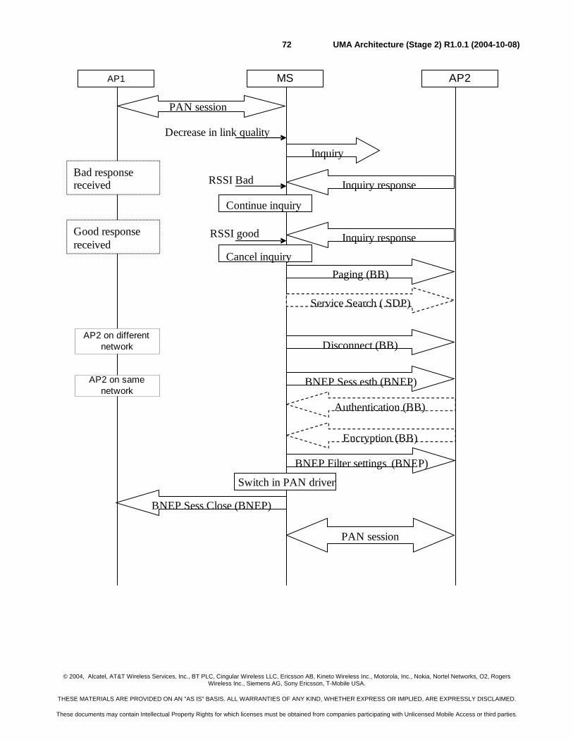
© 2004, Alcatel, AT&T Wireless Services, Inc., BT PLC, Cingular Wireless LLC, Ericsson AB, Kineto Wireless Inc., Motorola, Inc., Nokia, Nortel Networks, O2, Rogers Wireless Inc., Siemens AG, Sony Ericsson, T-Mobile USA.
THESE MATERIALS ARE PROVIDED ON AN "AS IS" BASIS. ALL WARRANTIES OF ANY KIND, WHETHER EXPRESS OR IMPLIED, ARE EXPRESSLY DISCLAIMED.
These documents may contain Intellectual Property Rights for which licenses must be obtained from companies participating with Unlicensed Mobile Access or third parties.
UMA Architecture (Stage 2) R1.0.1 (2004-10-08)72
AP1
Paging (BB)
Service Search ( SDP)
Authentication (BB)
Encryption (BB)
BNEP Sess estb (BNEP)
BNEP Filter settings (BNEP)
BNEP Sess Close (BNEP)
Switch in PAN driver
PAN session
Inquiry responseRSSI BadBad responsereceived
Inquiry responseRSSI good
Cancel inquiry
Good responsereceived
Continue inquiry
-Disconnect (BB)
MS AP2
PAN session
Inquiry
Decrease in link quality
AP2 on differentnetwork
AP2 on samenetwork
© 2004, Alcatel, AT&T Wireless Services, Inc., BT PLC, Cingular Wireless LLC, Ericsson AB, Kineto Wireless Inc., Motorola, Inc., Nokia, Nortel Networks, O2, Rogers Wireless Inc., Siemens AG, Sony Ericsson, T-Mobile USA.
THESE MATERIALS ARE PROVIDED ON AN "AS IS" BASIS. ALL WARRANTIES OF ANY KIND, WHETHER EXPRESS OR IMPLIED, ARE EXPRESSLY DISCLAIMED.
These documents may contain Intellectual Property Rights for which licenses must be obtained from companies participating with Unlicensed Mobile Access or third parties.
UMA Architecture (Stage 2) R1.0.1 (2004-10-08)73
Figure B.2.4.1 UMA-UMA handover.
1. A PAN session is ongoing.
2. The link quality drops below a threshold based on hysteresis. The MS shall start inquiry. 3. An inquiry response is received, but the link quality is poor.
4. Inquiry is continued.
5. An inquiry response is received and the link quality is good.
6. Inquiry is canceled.
7. The MS pages the AP.
8. The MS shall be able to perform an SDP search on the AP. The MS could cache results from previously performed SDP searches.
9. The SDP search revealed that the AP was a part of another network. The “Service name” in the SDP record is applied.
10. The PAN session is established.
11. The AP and/or MS could start authentication.
12. The AP and/or MS could start encryption.
13. The MS shall send filter settings to the AP.
14. The MS shall perform a switch in the PAN driver and close the BNEP session to the old AP.
15. The old BNEP session is closed.
16. The new Pan session is active.
B.2.4.1 Handling of inquiry during call
The Inquiry procedure during the call can be optimized based on these techniques:
- Sniff mode
- Interlaced inquiry scan
- Extensive inquiry scan
- Flush handling
B.2.4.1.1 Sniff mode handling
In order to support UMA-UMA handover and UMA to GSM handover, this policy must fulfill the following requirements:
- Whenever inquiry is made from the MS during a voice call MS sniff shall be applied. The MS shall leave sniff mode when the inquiry is completed. If the AP rejects the sniff request, inquiry should be postponed, until it’s possible to enter sniff mode.
- Sniff mode must never be applied during a call unless inquiry is running.
- Whenever a Bluetooth headset is applied with the MS, sniff mode shall be applied.
Both the AP and the MS shall be able to disable sniff mode.
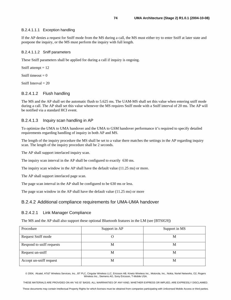
© 2004, Alcatel, AT&T Wireless Services, Inc., BT PLC, Cingular Wireless LLC, Ericsson AB, Kineto Wireless Inc., Motorola, Inc., Nokia, Nortel Networks, O2, Rogers Wireless Inc., Siemens AG, Sony Ericsson, T-Mobile USA.
THESE MATERIALS ARE PROVIDED ON AN "AS IS" BASIS. ALL WARRANTIES OF ANY KIND, WHETHER EXPRESS OR IMPLIED, ARE EXPRESSLY DISCLAIMED.
These documents may contain Intellectual Property Rights for which licenses must be obtained from companies participating with Unlicensed Mobile Access or third parties.
UMA Architecture (Stage 2) R1.0.1 (2004-10-08)74
B.2.4.1.1.1 Exception handling
If the AP denies a request for Sniff mode from the MS during a call, the MS must either try to enter Sniff at later state and postpone the inquiry, or the MS must perform the inquiry with full length.
B.2.4.1.1.2 Sniff parameters
These Sniff parameters shall be applied for during a call if inquiry is ongoing.
Sniff attempt = 12
Sniff timeout = 0
Sniff Interval = 20
B.2.4.1.2 Flush handling
The MS and the AP shall set the automatic flush to 5.625 ms. The UAM-MS shall set this value when entering sniff mode during a call. The AP shall set this value whenever the MS requires Sniff mode with a Sniff interval of 20 ms. The AP will be notified via a standard HCI event.
B.2.4.1.3 Inquiry scan handling in AP
To optimize the UMA to UMA handover and the UMA to GSM handover performance it’s required to specify detailed requirements regarding handling of inquiry in both AP and MS.
The length of the inquiry procedure the MS shall be set to a value there matches the settings in the AP regarding inquiry scan. The length of the inquiry procedure shall be 2 seconds.
The AP shall support interlaced inquiry scan.
The inquiry scan interval in the AP shall be configured to exactly 630 ms.
The inquiry scan window in the AP shall have the default value (11.25 ms) or more.
The AP shall support interlaced page scan.
The page scan interval in the AP shall be configured to be 630 ms or less.
The page scan window in the AP shall have the default value (11.25 ms) or more
B.2.4.2 Additional compliance requirements for UMA-UMA handover
B.2.4.2.1 Link Manager Compliance
The MS and the AP shall also support these optional Bluetooth features in the LM (see [BTSIG9])
Procedure Support in AP Support in MS
Request Sniff mode O M
Respond to sniff requests M M
Request un-sniff M M
Accept un-sniff request M M
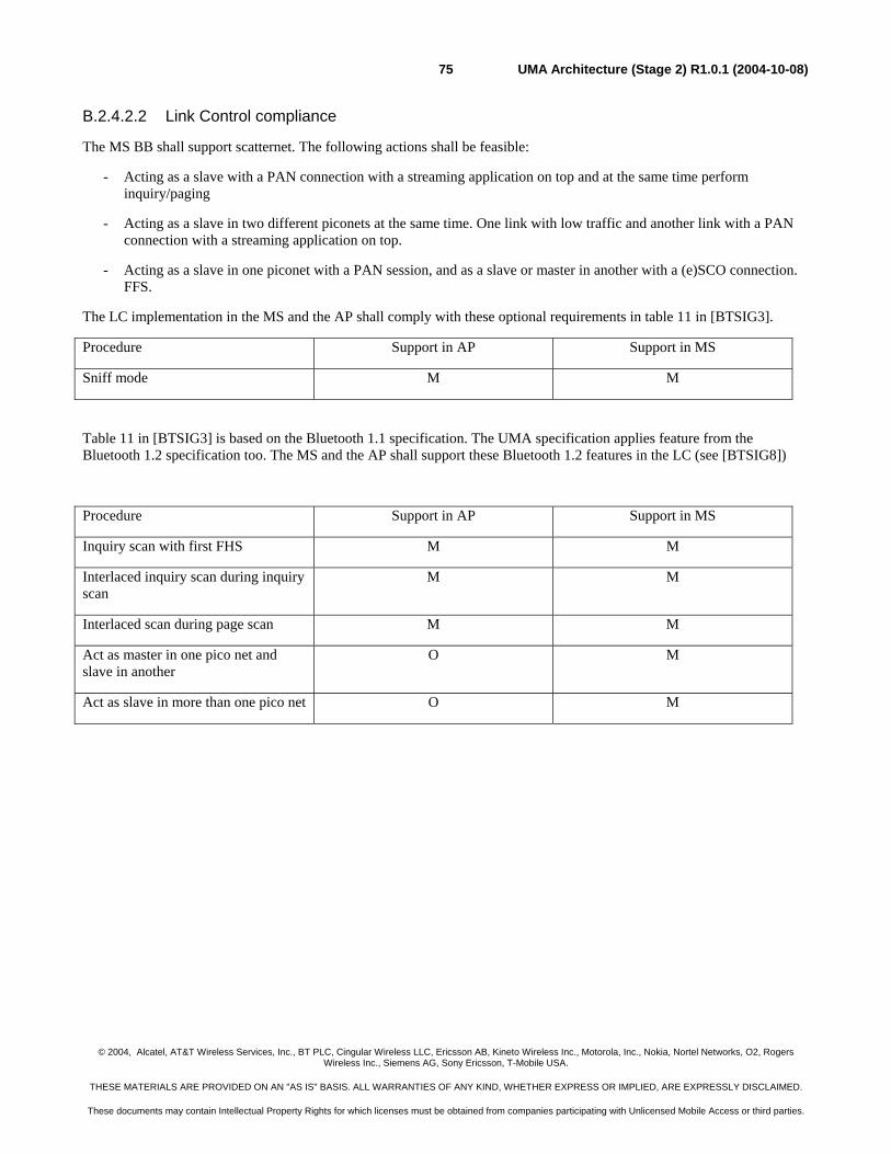
© 2004, Alcatel, AT&T Wireless Services, Inc., BT PLC, Cingular Wireless LLC, Ericsson AB, Kineto Wireless Inc., Motorola, Inc., Nokia, Nortel Networks, O2, Rogers Wireless Inc., Siemens AG, Sony Ericsson, T-Mobile USA.
THESE MATERIALS ARE PROVIDED ON AN "AS IS" BASIS. ALL WARRANTIES OF ANY KIND, WHETHER EXPRESS OR IMPLIED, ARE EXPRESSLY DISCLAIMED.
These documents may contain Intellectual Property Rights for which licenses must be obtained from companies participating with Unlicensed Mobile Access or third parties.
UMA Architecture (Stage 2) R1.0.1 (2004-10-08)75
B.2.4.2.2 Link Control compliance
The MS BB shall support scatternet. The following actions shall be feasible:
- Acting as a slave with a PAN connection with a streaming application on top and at the same time perform inquiry/paging
- Acting as a slave in two different piconets at the same time. One link with low traffic and another link with a PAN connection with a streaming application on top.
- Acting as a slave in one piconet with a PAN session, and as a slave or master in another with a (e)SCO connection. FFS.
The LC implementation in the MS and the AP shall comply with these optional requirements in table 11 in [BTSIG3].
Procedure Support in AP Support in MS
Sniff mode M M
Table 11 in [BTSIG3] is based on the Bluetooth 1.1 specification. The UMA specification applies feature from the Bluetooth 1.2 specification too. The MS and the AP shall support these Bluetooth 1.2 features in the LC (see [BTSIG8])
Procedure Support in AP Support in MS
Inquiry scan with first FHS M M
Interlaced inquiry scan during inquiry scan
M M
Interlaced scan during page scan M M
Act as master in one pico net and slave in another
O M
Act as slave in more than one pico net O M
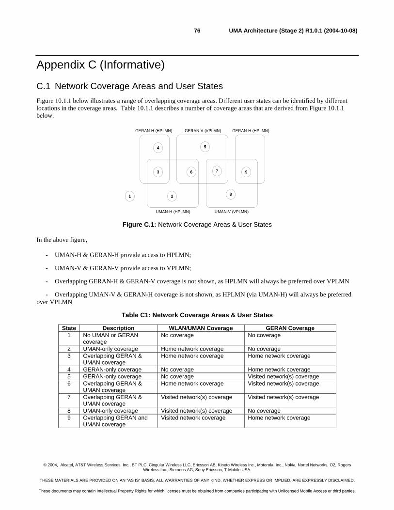
© 2004, Alcatel, AT&T Wireless Services, Inc., BT PLC, Cingular Wireless LLC, Ericsson AB, Kineto Wireless Inc., Motorola, Inc., Nokia, Nortel Networks, O2, Rogers Wireless Inc., Siemens AG, Sony Ericsson, T-Mobile USA.
THESE MATERIALS ARE PROVIDED ON AN "AS IS" BASIS. ALL WARRANTIES OF ANY KIND, WHETHER EXPRESS OR IMPLIED, ARE EXPRESSLY DISCLAIMED.
These documents may contain Intellectual Property Rights for which licenses must be obtained from companies participating with Unlicensed Mobile Access or third parties.
UMA Architecture (Stage 2) R1.0.1 (2004-10-08)76
Appendix C (Informative)
C.1 Network Coverage Areas and User States Figure 10.1.1 below illustrates a range of overlapping coverage areas. Different user states can be identified by different locations in the coverage areas. Table 10.1.1 describes a number of coverage areas that are derived from Figure 10.1.1 below.
GERAN-H (HPLMN) GERAN-V (VPLMN)
UMAN-H (HPLMN) UMAN-V (VPLMN)
1 2
3
4 5
6 7
8
GERAN-H (HPLMN)
9
Figure C.1: Network Coverage Areas & User States
In the above figure,
- UMAN-H & GERAN-H provide access to HPLMN;
- UMAN-V & GERAN-V provide access to VPLMN;
- Overlapping GERAN-H & GERAN-V coverage is not shown, as HPLMN will always be preferred over VPLMN
- Overlapping UMAN-V & GERAN-H coverage is not shown, as HPLMN (via UMAN-H) will always be preferred over VPLMN
Table C1: Network Coverage Areas & User States
State Description WLAN/UMAN Coverage GERAN Coverage 1 No UMAN or GERAN
coverage No coverage No coverage
2 UMAN-only coverage Home network coverage No coverage 3 Overlapping GERAN &
UMAN coverage Home network coverage Home network coverage
4 GERAN-only coverage No coverage Home network coverage 5 GERAN-only coverage No coverage Visited network(s) coverage 6 Overlapping GERAN &
UMAN coverage Home network coverage Visited network(s) coverage
7 Overlapping GERAN & UMAN coverage
Visited network(s) coverage Visited network(s) coverage
8 UMAN-only coverage Visited network(s) coverage No coverage 9 Overlapping GERAN and
UMAN coverage Visited network coverage Home network coverage
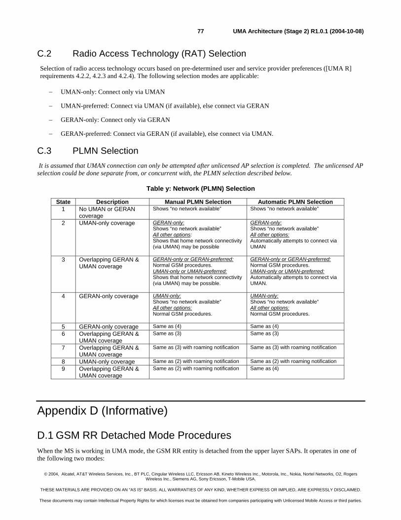
© 2004, Alcatel, AT&T Wireless Services, Inc., BT PLC, Cingular Wireless LLC, Ericsson AB, Kineto Wireless Inc., Motorola, Inc., Nokia, Nortel Networks, O2, Rogers Wireless Inc., Siemens AG, Sony Ericsson, T-Mobile USA.
THESE MATERIALS ARE PROVIDED ON AN "AS IS" BASIS. ALL WARRANTIES OF ANY KIND, WHETHER EXPRESS OR IMPLIED, ARE EXPRESSLY DISCLAIMED.
These documents may contain Intellectual Property Rights for which licenses must be obtained from companies participating with Unlicensed Mobile Access or third parties.
UMA Architecture (Stage 2) R1.0.1 (2004-10-08)77
C.2 Radio Access Technology (RAT) Selection Selection of radio access technology occurs based on pre-determined user and service provider preferences ([UMA R] requirements 4.2.2, 4.2.3 and 4.2.4). The following selection modes are applicable:
− UMAN-only: Connect only via UMAN
− UMAN-preferred: Connect via UMAN (if available), else connect via GERAN
− GERAN-only: Connect only via GERAN
− GERAN-preferred: Connect via GERAN (if available), else connect via UMAN.
C.3 PLMN Selection It is assumed that UMAN connection can only be attempted after unlicensed AP selection is completed. The unlicensed AP selection could be done separate from, or concurrent with, the PLMN selection described below.
Table y: Network (PLMN) Selection
State Description Manual PLMN Selection Automatic PLMN Selection 1 No UMAN or GERAN
coverage Shows “no network available” Shows “no network available”
2 UMAN-only coverage GERAN-only: Shows “no network available” All other options: Shows that home network connectivity (via UMAN) may be possible
GERAN-only: Shows “no network available” All other options: Automatically attempts to connect via UMAN
3 Overlapping GERAN & UMAN coverage
GERAN-only or GERAN-preferred: Normal GSM procedures. UMAN-only or UMAN-preferred: Shows that home network connectivity (via UMAN) may be possible.
GERAN-only or GERAN-preferred: Normal GSM procedures. UMAN-only or UMAN-preferred: Automatically attempts to connect via UMAN.
4 GERAN-only coverage UMAN-only: Shows “no network available” All other options: Normal GSM procedures.
UMAN-only: Shows “no network available” All other options: Normal GSM procedures.
5 GERAN-only coverage Same as (4) Same as (4) 6 Overlapping GERAN &
UMAN coverage Same as (3)
Same as (3)
7 Overlapping GERAN & UMAN coverage
Same as (3) with roaming notification Same as (3) with roaming notification
8 UMAN-only coverage Same as (2) with roaming notification Same as (2) with roaming notification 9 Overlapping GERAN &
UMAN coverage Same as (2) with roaming notification Same as (4)
Appendix D (Informative)
D.1 GSM RR Detached Mode Procedures When the MS is working in UMA mode, the GSM RR entity is detached from the upper layer SAPs. It operates in one of the following two modes:
© 2004, Alcatel, AT&T Wireless Services, Inc., BT PLC, Cingular Wireless LLC, Ericsson AB, Kineto Wireless Inc., Motorola, Inc., Nokia, Nortel Networks, O2, Rogers Wireless Inc., Siemens AG, Sony Ericsson, T-Mobile USA.
THESE MATERIALS ARE PROVIDED ON AN "AS IS" BASIS. ALL WARRANTIES OF ANY KIND, WHETHER EXPRESS OR IMPLIED, ARE EXPRESSLY DISCLAIMED.
These documents may contain Intellectual Property Rights for which licenses must be obtained from companies participating with Unlicensed Mobile Access or third parties.
UMA Architecture (Stage 2) R1.0.1 (2004-10-08)78
• Hibernation mode
• Detached cell reselection mode
D.1.1 Hibernation Mode The GSM RR entity in MS enters hibernation mode when the MS switches from GSM mode to UMA mode.
In this mode, the GSM RR entity shuts off the GSM radio in order to extend battery life in UMA mode. Before going into hibernation mode:
1. If there is a GSM camping cell available, the GSM RR keeps a copy of the most recent system information of the camping cell, and then shuts down layer 1 and powers down the GSM radio.
2. If there is no cell available, the GSM RR immediately stops layer 1 and shuts off the GSM radio.
3. If PLMN search is in progress, it continues until either a camping cell is selected or when it is concluded that no cell is available for the moment. It then proceeds according to step 1 or step 2 above.
The GSM RR entity exits out of hibernation mode under the following conditions:
1. When MS changes AP it is attached to, as a result of intra-UMA roving or handover;
2. When MS detects unlicensed radio link has dropped below certain threshold that triggers rove-out or handover-out (or some time prior to this event);
3. When unlicensed radio link is lost altogether.
Upon exiting hibernation mode, and with the stored copy of the system information, the GSM RR entity can perform instant wakeup instead of going through either normal cell selection procedure or stored list cell selection procedure (See §6.2/6.3 of 3GPP TS 45.008). To do so, the mobile tunes onto the ARFCN of the target cell and searches for the FCCH. Once it captures the synchronization to the FCCH/SCH of the target cell, it restores all BCCH data from previously stored snapshot and assumes the BCCH data is up to date. If the target cell is not found within two FCCH cycles (about 92ms), or if snapshot BCCH data is not available, the mobile shall go through the normal cell selection procedure or stored list cell selection procedure.
After that, the GSM RR entity moves into the “detached cell reselection” mode (see next section).
If the MS is still in UMA mode (i.e. due to intra-UMA roving or handover), then the GSM RR entity can re-enter hibernate mode.
If the MS switches to GSM mode (i.e. due to UMA-to-GERAN roving or handover), then the GSM RR entity will become active and attached to the NAS layer (and UMA RR entity will detach from the NAS layer).
D.1.2 Detached Cell Reselection Mode In this mode, the GSM RR continues the standard cell selection/reselection procedures. However, since it is detached from the NAS and not serving upper layers, the GSM entity shall not inform the MM layer about the selection of a new cell and/or the change of system information of the current camping cell; also, the detection of newly found GSM PLMN shall not trigger NAS to change selected PLMN.
From the MM layer’s point of view, the current serving cell is the UMA cell.
The GSM RR entity in this mode is always looking for the best cell to camp on in terms of C1/C2 or C31/C32 criteria. When UMA-to-GERAN roving or handover occurs, the MS can immediately return to GSM mode (using the currently available GSM cell information) and be ready for service.
If the GSM RR entity detects a paging match, it shall silently discard the paging request message.
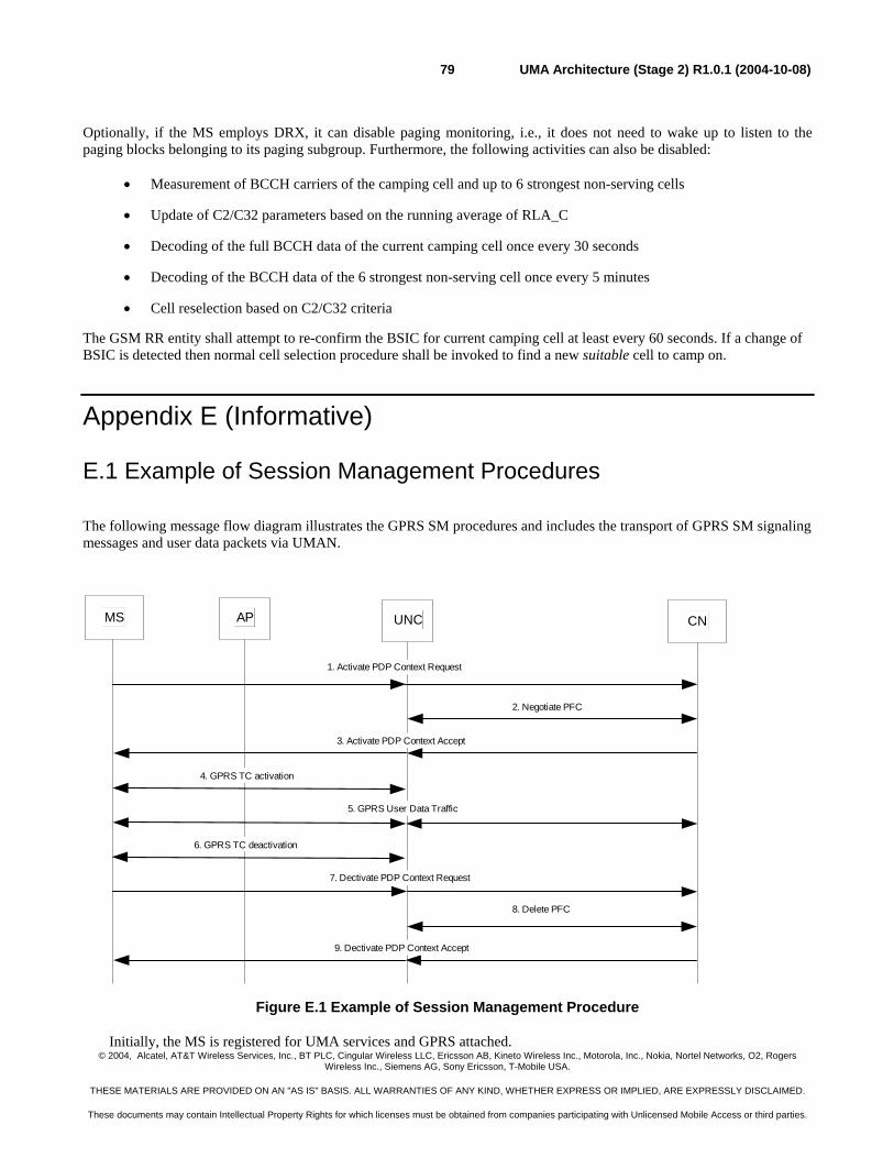
© 2004, Alcatel, AT&T Wireless Services, Inc., BT PLC, Cingular Wireless LLC, Ericsson AB, Kineto Wireless Inc., Motorola, Inc., Nokia, Nortel Networks, O2, Rogers Wireless Inc., Siemens AG, Sony Ericsson, T-Mobile USA.
THESE MATERIALS ARE PROVIDED ON AN "AS IS" BASIS. ALL WARRANTIES OF ANY KIND, WHETHER EXPRESS OR IMPLIED, ARE EXPRESSLY DISCLAIMED.
These documents may contain Intellectual Property Rights for which licenses must be obtained from companies participating with Unlicensed Mobile Access or third parties.
UMA Architecture (Stage 2) R1.0.1 (2004-10-08)79
Optionally, if the MS employs DRX, it can disable paging monitoring, i.e., it does not need to wake up to listen to the paging blocks belonging to its paging subgroup. Furthermore, the following activities can also be disabled:
• Measurement of BCCH carriers of the camping cell and up to 6 strongest non-serving cells
• Update of C2/C32 parameters based on the running average of RLA_C
• Decoding of the full BCCH data of the current camping cell once every 30 seconds
• Decoding of the BCCH data of the 6 strongest non-serving cell once every 5 minutes
• Cell reselection based on C2/C32 criteria
The GSM RR entity shall attempt to re-confirm the BSIC for current camping cell at least every 60 seconds. If a change of BSIC is detected then normal cell selection procedure shall be invoked to find a new suitable cell to camp on.
Appendix E (Informative)
E.1 Example of Session Management Procedures The following message flow diagram illustrates the GPRS SM procedures and includes the transport of GPRS SM signaling messages and user data packets via UMAN.
MS UNC CN
2. Negotiate PFC
8. Delete PFC
AP
1. Activate PDP Context Request
3. Activate PDP Context Accept
5. GPRS User Data Traffic
7. Dectivate PDP Context Request
4. GPRS TC activation
6. GPRS TC deactivation
9. Dectivate PDP Context Accept
Figure E.1 Example of Session Management Procedure
Initially, the MS is registered for UMA services and GPRS attached.
© 2004, Alcatel, AT&T Wireless Services, Inc., BT PLC, Cingular Wireless LLC, Ericsson AB, Kineto Wireless Inc., Motorola, Inc., Nokia, Nortel Networks, O2, Rogers Wireless Inc., Siemens AG, Sony Ericsson, T-Mobile USA.
THESE MATERIALS ARE PROVIDED ON AN "AS IS" BASIS. ALL WARRANTIES OF ANY KIND, WHETHER EXPRESS OR IMPLIED, ARE EXPRESSLY DISCLAIMED.
These documents may contain Intellectual Property Rights for which licenses must be obtained from companies participating with Unlicensed Mobile Access or third parties.
UMA Architecture (Stage 2) R1.0.1 (2004-10-08)80
1. The MS initiates PDP Context activation procedure. The Activate PDP Context Request message is forwarded to the Core Network using the URLC transport for GPRS SM messages described in sub-clause 9.13.2.
2. Optionally, if the packet flow management is supported, the corresponding PFC is negotiated.
3. Assuming successful PDP Context activation, the Core Network replies with an Activate PDP Context Accept message. The message is forwarded to the MS using the URLC transport for GPRS SM messages described in sub-clause 9.13.2.
4. Optionally, if the URLC is in the URLC-STANDBY state, the corresponding URLC TC is activated as described in sub-clause 9.12.
5. GPRS user data traffic is tunnelled between the MS and Core Network using the URLC user data transport mechanism described in sub-clause 9.13.1.
6. Optionally, if the URLC channel timer expires, the corresponding URLC TC is deactivated.
7. The MS initiates PDP Context deactivation procedure. The Deactivate PDP Context Request message is forwarded to the Core Network using the URLC transport for GPRS SM messages described in sub-clause 9.13.2.
8. Optionally, if the PFC was created for this PDP context, it is deleted now.
9. The Core Network replies with a Deactivate PDP Context Accept message. The message is forwarded to the MS using the URLC transport for GPRS SM messages described in sub-clause 9.13.2.