Embed Size (px)
Citation preview
DANISH GPS CENTER
Carrier Tracking Loop;Loop FilterGPS Signals And Receiver Technology MM12Darius Plauš[email protected]
DANISH GPS CENTERToday’s Subjects
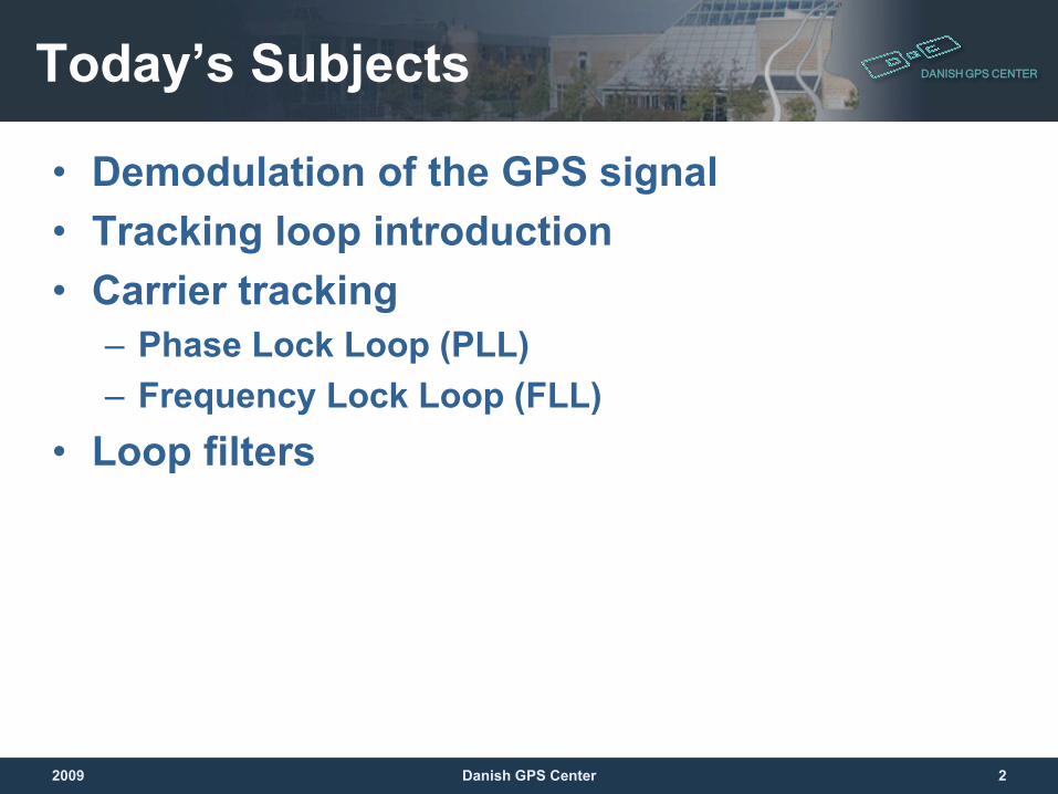
• Demodulation of the GPS signal• Tracking loop introduction• Carrier tracking
– Phase Lock Loop (PLL)– Frequency Lock Loop (FLL)
• Loop filters
2009 2Danish GPS Center
DANISH GPS CENTER
DemodulationOr how to turn the radio waves back into the data
message that we are interested in
2009 3Danish GPS Center
DANISH GPS CENTERDemodulation
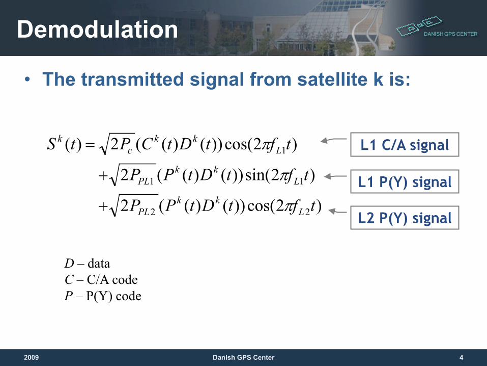
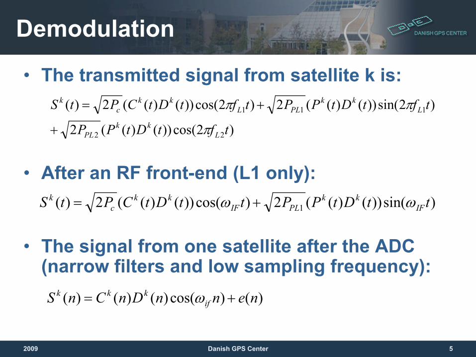
• The transmitted signal from satellite k is:
)2cos())()((2
)2sin())()((2
)2cos())()((2)(
22
11
1
tftDtPP
tftDtPP
tftDtCPtS
Lkk
PL
Lkk
PL
Lkk
ck
π
π
π
+
+
= L1 C/A signal
L1 P(Y) signal
L2 P(Y) signal
D – dataC – C/A codeP – P(Y) code
2009 4Danish GPS Center
DANISH GPS CENTERDemodulation
• The transmitted signal from satellite k is:
• After an RF front-end (L1 only):
• The signal from one satellite after the ADC (narrow filters and low sampling frequency):
)2cos())()((2
)2sin())()((2)2cos())()((2)(
22
111
tftDtPP
tftDtPPtftDtCPtS
Lkk
PL
Lkk
PLLkk
ck
π
ππ
+
+=
)()cos()()()( nennDnCnS ifkkk += ω
)sin())()((2)cos())()((2)( 1 ttDtPPttDtCPtS IFkk
PLIFkk
ck ωω +=
2009 5Danish GPS Center
DANISH GPS CENTERDemodulation
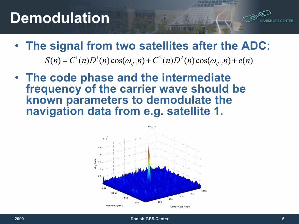
• The signal from two satellites after the ADC:
• The code phase and the intermediate frequency of the carrier wave should be known parameters to demodulate the navigation data from e.g. satellite 1.
)()cos()()()cos()()()( 222
111 nennDnCnnDnCnS ifif ++= ωω
2009 6Danish GPS Center
DANISH GPS CENTERDemodulation
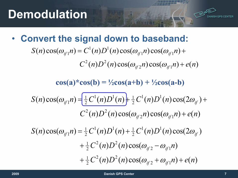
• Convert the signal down to baseband:
)()cos()cos()()(
)cos()cos()()()cos()(
1222
1111
1
nennnDnC
nnnDnCnnS
ifif
ififif
+
+=
ωω
ωωω
)()cos()cos()()(
)2cos()()()()()cos()(
1222
112111
21
1
nennnDnC
nDnCnDnCnnS
ifif
ifif
+
++=
ωω
ωω
cos(a)*cos(b) = ½cos(a+b) + ½cos(a-b)
)()cos()()(
)cos()()(
)2cos()()()()()cos()(
1222
21
1222
21
112111
21
1
nennDnC
nnDnC
nDnCnDnCnnS
ifif
ifif
ifif
+++
−+
+=
ωω
ωω
ωω
2009 7Danish GPS Center
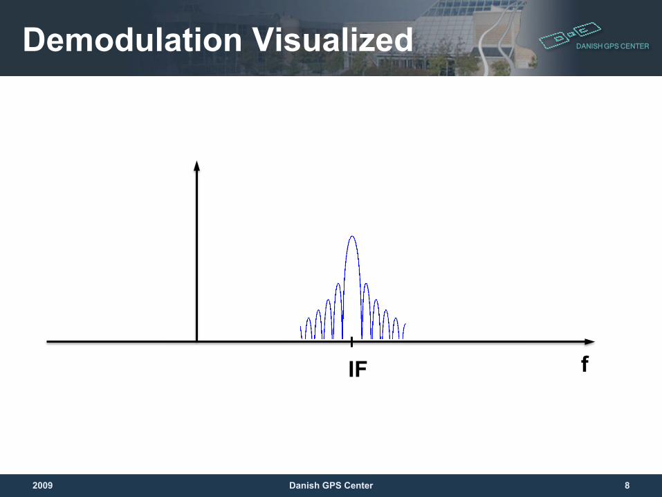
DANISH GPS CENTERDemodulation Visualized
fIF
2009 8Danish GPS Center
DANISH GPS CENTERDemodulation
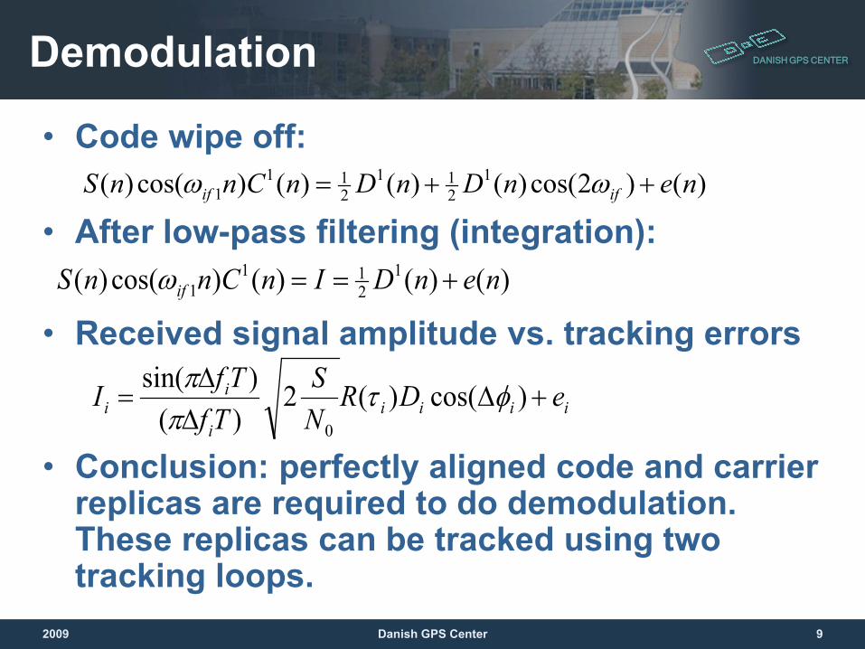
• Code wipe off:
• After low-pass filtering (integration):
• Received signal amplitude vs. tracking errors
• Conclusion: perfectly aligned code and carrier replicas are required to do demodulation. These replicas can be tracked using two tracking loops.
)()2cos()()()()cos()( 1211
211
1 nenDnDnCnnS ifif ++= ωω
)()()()cos()( 1211
1 nenDInCnnS if +==ω
iiiii
ii eDR
NS
TfTfI +∆
∆∆
= )cos()(2)(
)sin(
0
φτππ
2009 9Danish GPS Center
DANISH GPS CENTER
Tracking LoopA way to generate exact copy of the received signal
2009 10Danish GPS Center
DANISH GPS CENTER
What does tracking do and why?• The main goal is to receive the GNSS signal
”as clear and loud” as possible – the local carrier and spreading code must be well aligned with the ones in the signal
• GNSS adds one more requirement: to track signal arrival (time) as precise as possible
• Advanced receivers can detect multipath to some extent
• Additional task can be signal quality monitoring
2009 11Danish GPS Center
DANISH GPS CENTERThe Tracking Loop Idea
• Generate a local signal• Correlate it with the received signal• Measure (time/code-phase, frequency, phase)
error between the local and the received signals
• Steer local signal generators to minimize the error
• Pass demodulated data bit value stream to the data processing task
• Repeat procedure
2009 12Danish GPS Center
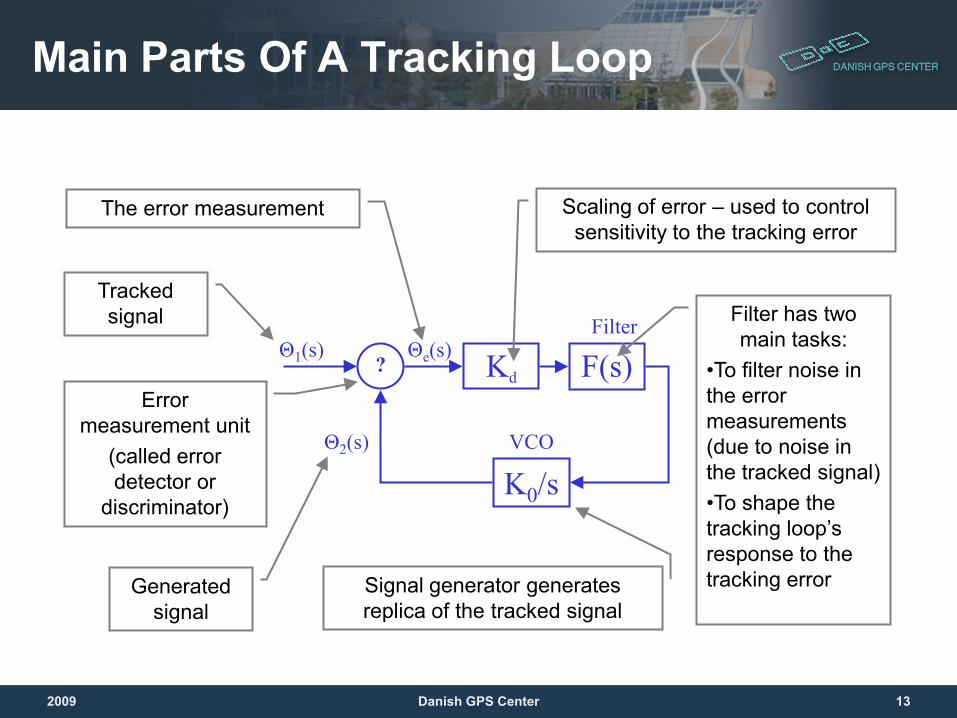
DANISH GPS CENTERMain Parts Of A Tracking Loop
F(s)Filter
Kd
K0/sVCO
Θ1(s)
Θ2(s)
Θe(s)
Tracked signal
Generated signal
Error measurement unit
(called error detector or
discriminator)
The error measurement Scaling of error – used to control sensitivity to the tracking error
Filter has two main tasks:
•To filter noise in the error measurements (due to noise in the tracked signal)•To shape the tracking loop’s response to the tracking errorSignal generator generates
replica of the tracked signal
?
2009 13Danish GPS Center
DANISH GPS CENTERTypes Of Tracking Loops
• There are 3 main types of the tracking loops depending on the tracked property of the tracked signal:– Phase lock loop (PLL)– Frequency lock loop (FLL)– Delay lock loop (DLL)
• There are few error detectors for each type of the tracking loop with different properties
• Variations of filter parameters will shape the filter response and amount of noise filtering
2009 14Danish GPS Center
DANISH GPS CENTERPlan For The Tracking Topic
• PLL (FLL) and DLL are explained in sections on carrier and code tracking
• Each section will also cover a set of error detectors applicable in a given tracking loop
• Tracking loop filter is explained in a separate section as the same theory is used for all types of tracking loops
2009 15Danish GPS Center
DANISH GPS CENTER
The Carrier Tracking LoopThe Phase Locked Loop (PLL)
2009 16Danish GPS Center
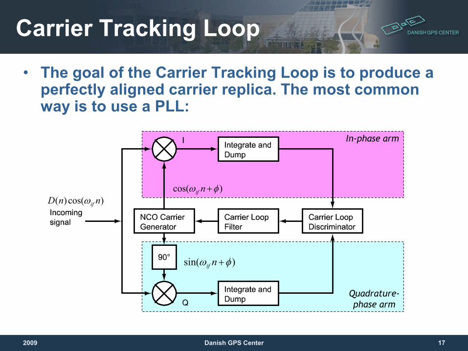
DANISH GPS CENTERCarrier Tracking Loop
• The goal of the Carrier Tracking Loop is to produce a perfectly aligned carrier replica. The most common way is to use a PLL:
)cos( φω +nif
)cos()( nnD ifω
)sin( φω +nif
Quadrature-phase arm
In-phase arm
2009 17Danish GPS Center
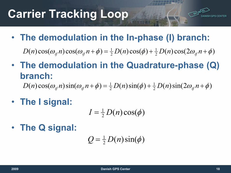
DANISH GPS CENTERCarrier Tracking Loop
• The demodulation in the In-phase (I) branch:
• The demodulation in the Quadrature-phase (Q) branch:
• The I signal:
• The Q signal:
)2cos()()cos()()cos()cos()( 21
21 φωφφωω ++=+ nnDnDnnnD ififif
)cos()(21 φnDI =
)2sin()()sin()()sin()cos()( 21
21 φωφφωω ++=+ nnDnDnnnD ififif
)sin()(21 φnDQ =
2009 18Danish GPS Center
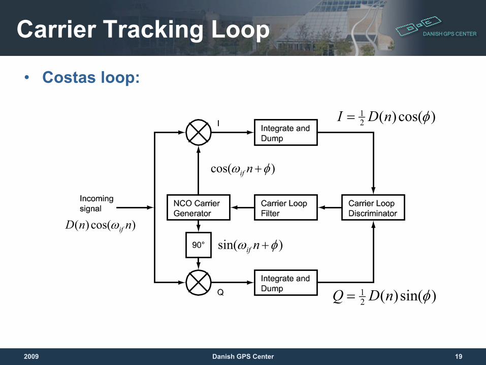
DANISH GPS CENTERCarrier Tracking Loop
• Costas loop:
)cos()(21 φnDI =
)cos( φω +nif
)cos()( nnD ifω
)sin( φω +nif
)sin()(21 φnDQ =
2009 19Danish GPS Center
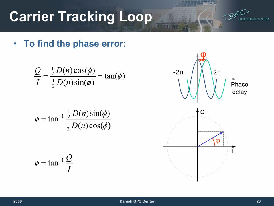
DANISH GPS CENTERCarrier Tracking Loop
• To find the phase error:
Phase delay
-2π)tan()sin()()cos()(
2121
φφφ
==nDnD
IQ
)cos()()sin()(tan
2121
1
φφ
φnDnD−=
IQ1tan−=φ
Q
I
φ
φ
2π
2009 20Danish GPS Center
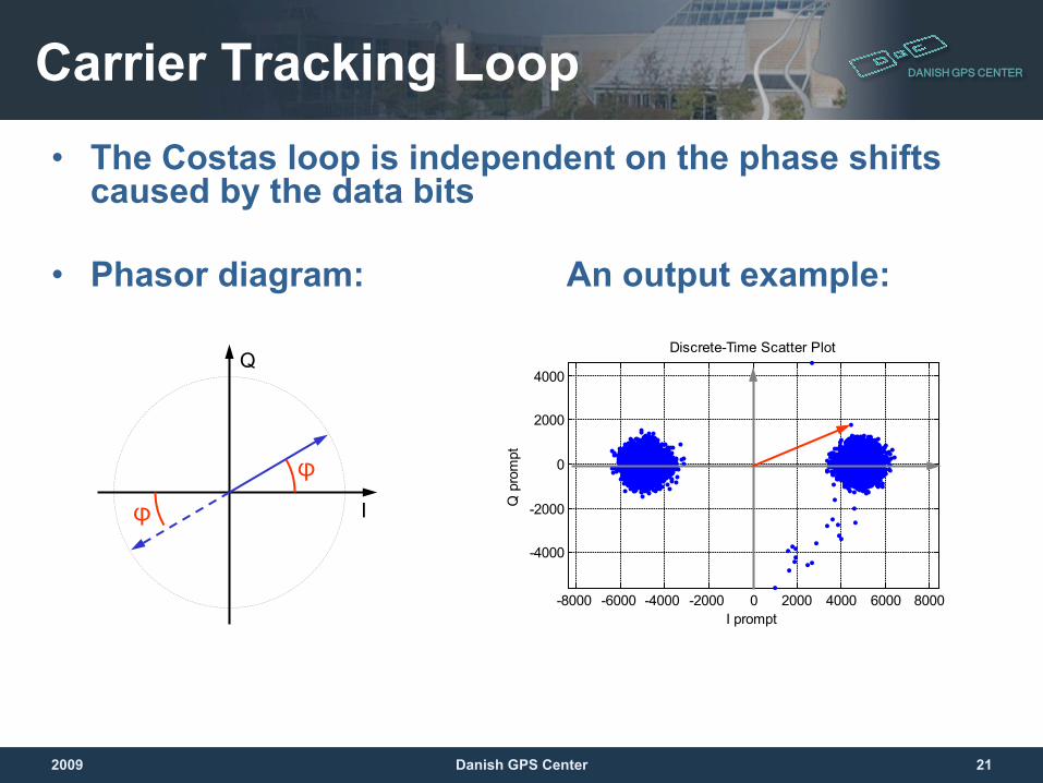
DANISH GPS CENTERCarrier Tracking Loop• The Costas loop is independent on the phase shifts
caused by the data bits
• Phasor diagram: An output example:
-8000 -6000 -4000 -2000 0 2000 4000 6000 8000
-4000
-2000
0
2000
4000
Discrete-Time Scatter Plot
I prompt
Q p
rom
pt
Q
I
φ
φ
2009 21Danish GPS Center
DANISH GPS CENTERCarrier Tracking Loop
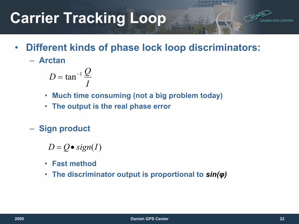
• Different kinds of phase lock loop discriminators:– Arctan
• Much time consuming (not a big problem today)• The output is the real phase error
– Sign product
• Fast method• The discriminator output is proportional to sin(φ)
IQD 1tan−=
)(IsignQD •=
2009 22Danish GPS Center
DANISH GPS CENTERCarrier Tracking Loop
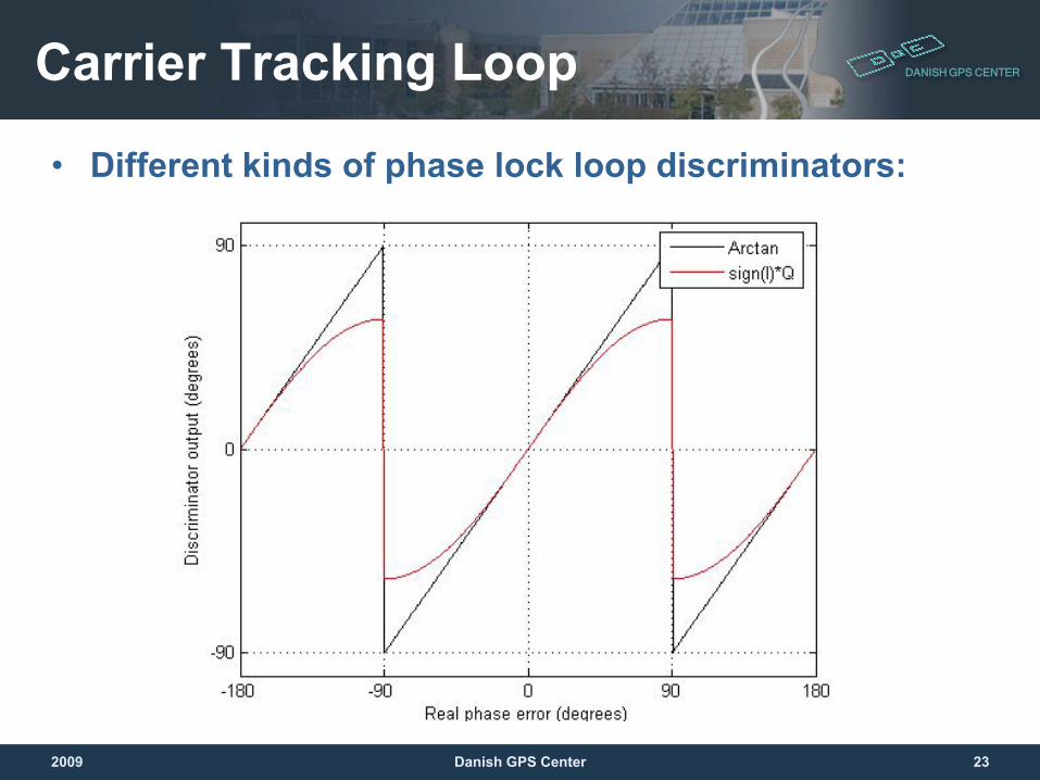
• Different kinds of phase lock loop discriminators:
2009 23Danish GPS Center
DANISH GPS CENTERCarrier Tracking Loop
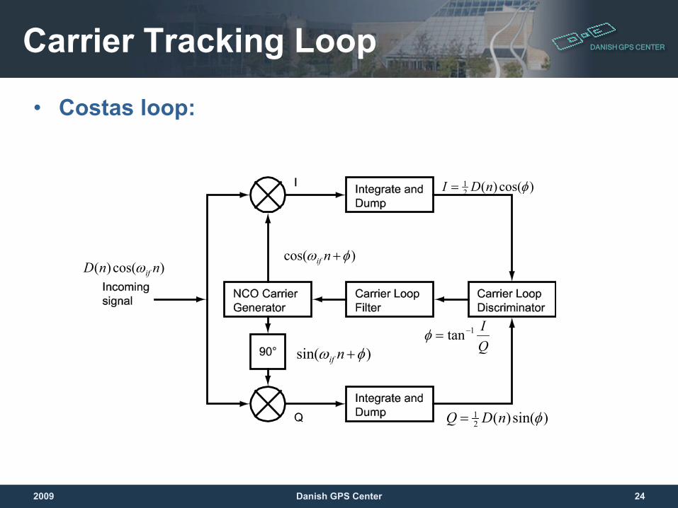
• Costas loop:
)cos()(21 φnDI =
)cos( φω +nif)cos()( nnD ifω
)sin( φω +nif
)sin()(21 φnDQ =
QI1tan−=φ
2009 24Danish GPS Center
DANISH GPS CENTERCarrier Tracking Loop
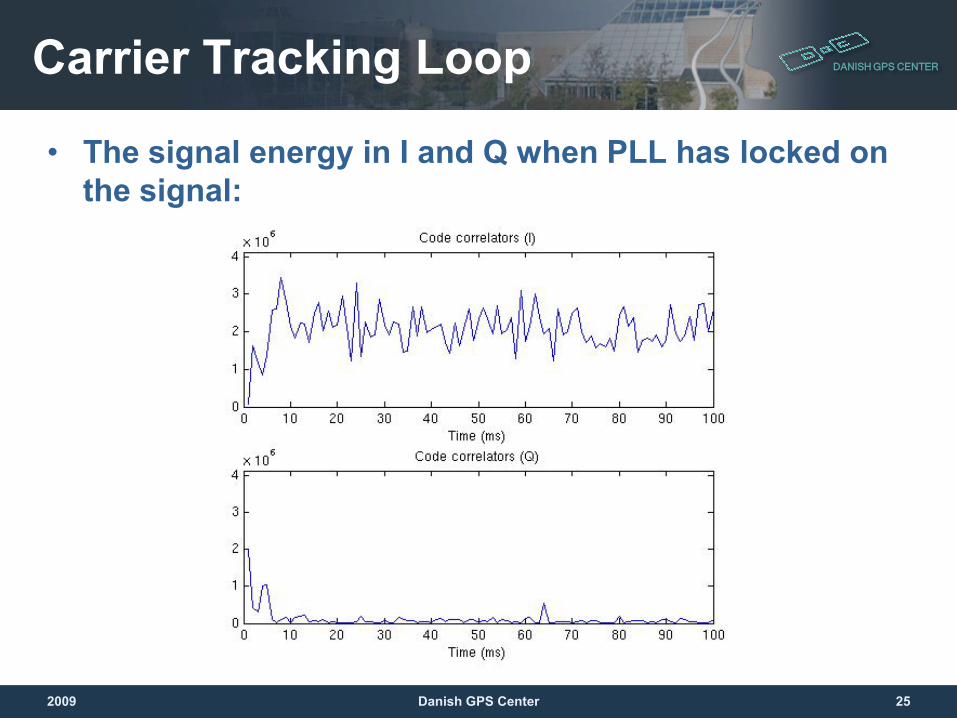
• The signal energy in I and Q when PLL has locked on the signal:
2009 25Danish GPS Center

DANISH GPS CENTER
The Carrier Tracking LoopThe Frequency Locked Loop (FLL)
2009 26Danish GPS Center
DANISH GPS CENTERFrequency Lock Loop
• The discrimators are a bit different than in PLL. They measure change in carrier phase over an interval of time.
• Less noise sensitive than PLL – it can track at lower SNR
• The tracking loop has more noise than PLL• Can be used for the re-acquisition or pull-in
states due to bigger frequency lock range
2009 27Danish GPS Center
DANISH GPS CENTER
Loop Filters
2009 28Danish GPS Center
DANISH GPS CENTER
Why The Filter Is Needed Anyway?• The error measurement is there, so just
correct the generator frequency and job is done, right?
• The answer is NO:– There is an error measurement noise (even at good
SNR)– There is a stady state error caused by Doppler
2009 29Danish GPS Center
DANISH GPS CENTERThe Typical Tracking Loop
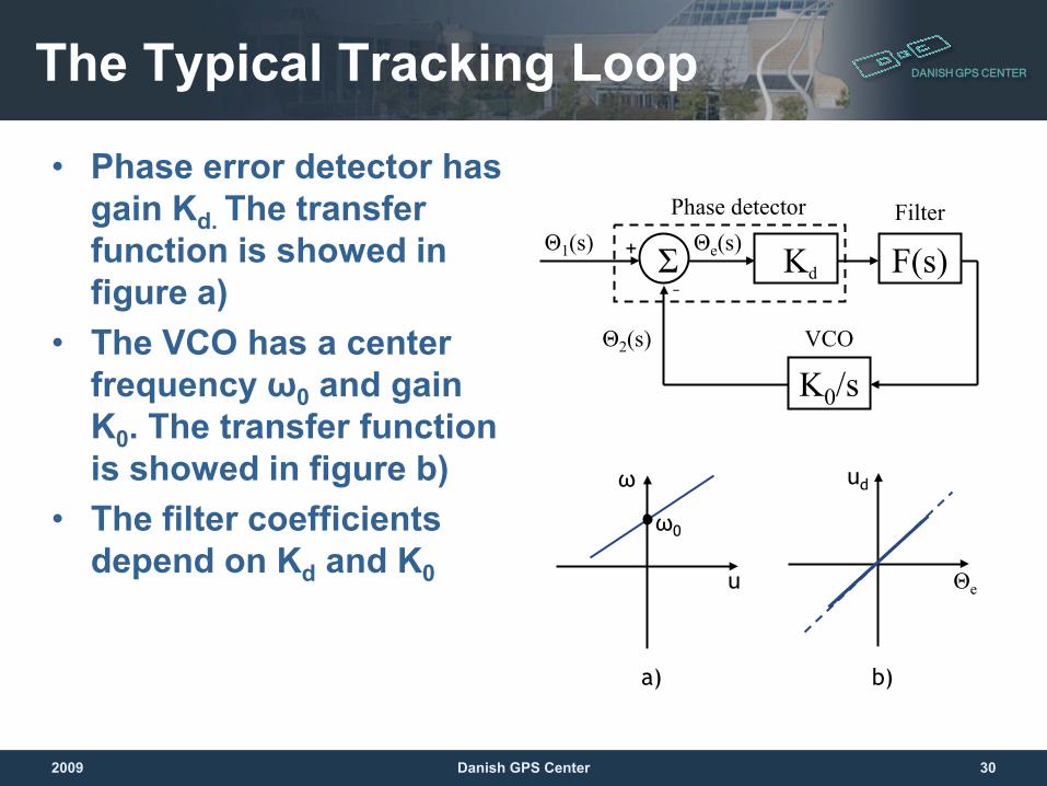
• Phase error detector has gain Kd. The transfer function is showed in figure a)
• The VCO has a center frequency ω0 and gain K0. The transfer function is showed in figure b)
• The filter coefficients depend on Kd and K0
Σ F(s)
Phase detector Filter
Kd
K0/sVCO
Θ1(s)
Θ2(s)
Θe(s)
u
ω0
ω ud
Θe
a) b)
–
+
2009 30Danish GPS Center
DANISH GPS CENTER
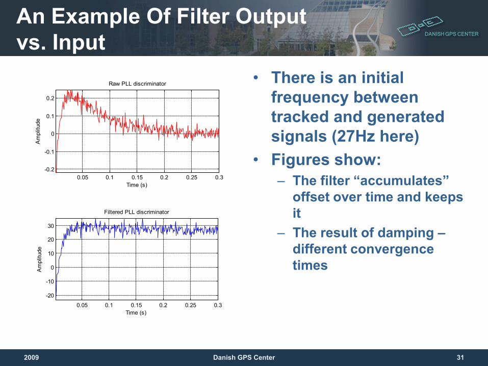
• There is an initial frequency between tracked and generated signals (27Hz here)
• Figures show: – The filter “accumulates”
offset over time and keeps it
– The result of damping –different convergence times
An Example Of Filter Output vs. Input
0.05 0.1 0.15 0.2 0.25 0.3
-20
-10
0
10
20
30
Time (s)
Am
plitu
de
Filtered PLL discriminator
0.05 0.1 0.15 0.2 0.25 0.3-0.2
-0.1
0
0.1
0.2
Time (s)
Am
plitu
de
Raw PLL discriminator
2009 31Danish GPS Center
DANISH GPS CENTER
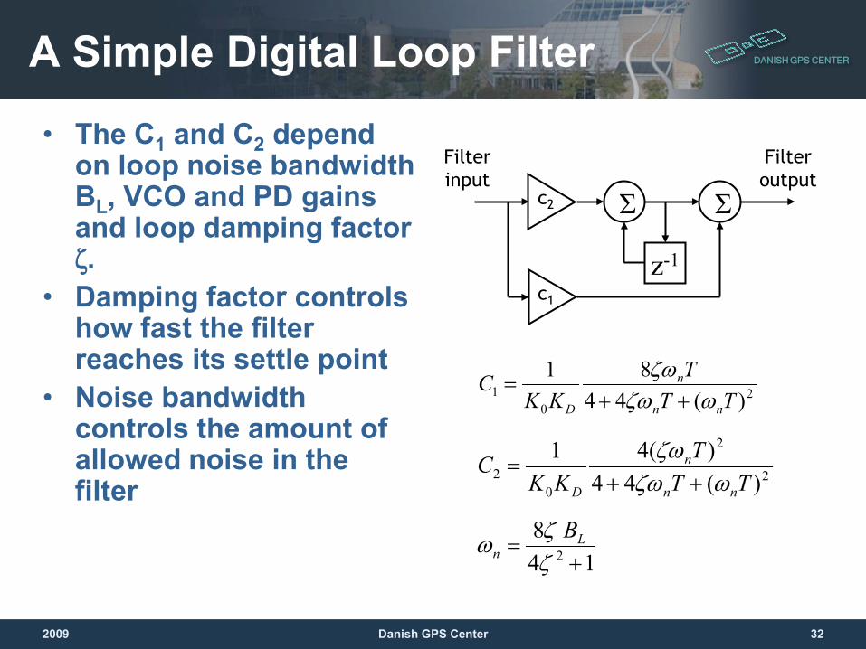
• The C1 and C2 depend on loop noise bandwidth BL, VCO and PD gains and loop damping factor ζ.
• Damping factor controls how fast the filter reaches its settle point
• Noise bandwidth controls the amount of allowed noise in the filter
A Simple Digital Loop Filter
20
1 )(4481
TTT
KKC
nn
n
D ωζωζω
++=
z-1
Σ Σc2
c1
Filter input
Filter output
2
2
02 )(44
)(41TT
TKK
Cnn
n
D ωζωζω
++=
148
2 +=
ζζω L
nB
2009 32Danish GPS Center
DANISH GPS CENTER
2008 Danish GPS Center 33
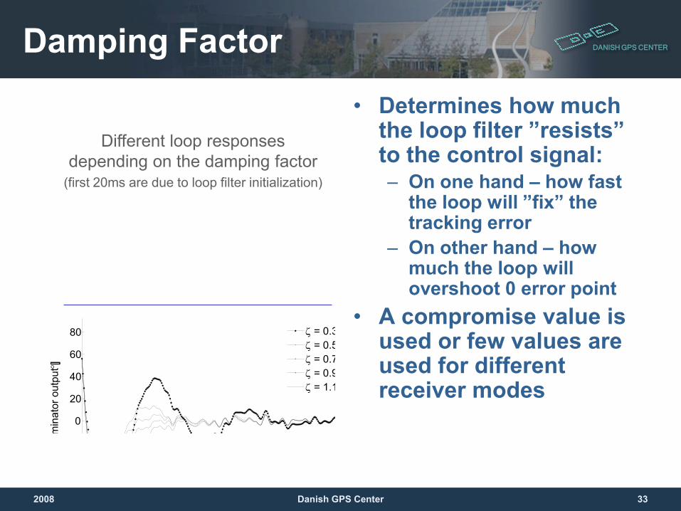
• Determines how much the loop filter ”resists” to the control signal:– On one hand – how fast
the loop will ”fix” the tracking error
– On other hand – how much the loop will overshoot 0 error point
• A compromise value is used or few values are used for different receiver modes
Damping Factor
Different loop responses depending on the damping factor
(first 20ms are due to loop filter initialization)
0
20
40
60
80
m
inat
or o
utpu
t [°]
ζ = 0.3ζ = 0.5ζ = 0.7ζ = 0.9ζ = 1.1
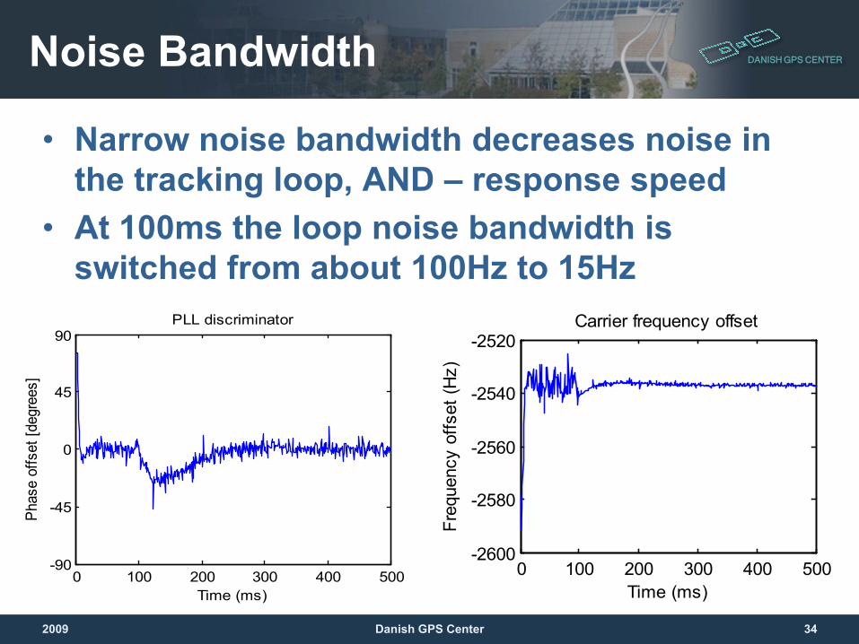
DANISH GPS CENTERNoise Bandwidth
• Narrow noise bandwidth decreases noise in the tracking loop, AND – response speed
• At 100ms the loop noise bandwidth is switched from about 100Hz to 15Hz
0 100 200 300 400 500-2600
-2580
-2560
-2540
-2520Carrier frequency offset
Time (ms)
Freq
uenc
y of
fset
(Hz)
0 100 200 300 400 500-90
-45
0
45
90PLL discriminator
Time (ms)
Phas
e of
fset
[deg
rees
]
2009 34Danish GPS Center
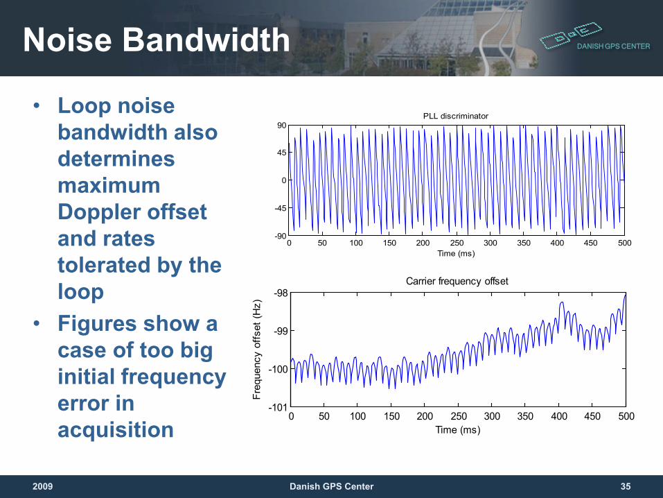
DANISH GPS CENTERNoise Bandwidth
• Loop noise bandwidth also determines maximum Doppler offset and rates tolerated by the loop
• Figures show a case of too big initial frequency error in acquisition
0 50 100 150 200 250 300 350 400 450 500-90
-45
0
45
90PLL discriminator
Time (ms)
0 50 100 150 200 250 300 350 400 450 500-101
-100
-99
-98Carrier frequency offset
Time (ms)
Freq
uenc
y of
fset
(Hz)
2009 35Danish GPS Center
DANISH GPS CENTER
2008 Danish GPS Center 36
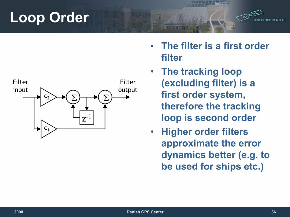
• The filter is a first order filter
• The tracking loop (excluding filter) is a first order system, therefore the tracking loop is second order
• Higher order filters approximate the error dynamics better (e.g. to be used for ships etc.)
Loop Order
z-1
Σ Σc2
c1
Filter input
Filter output
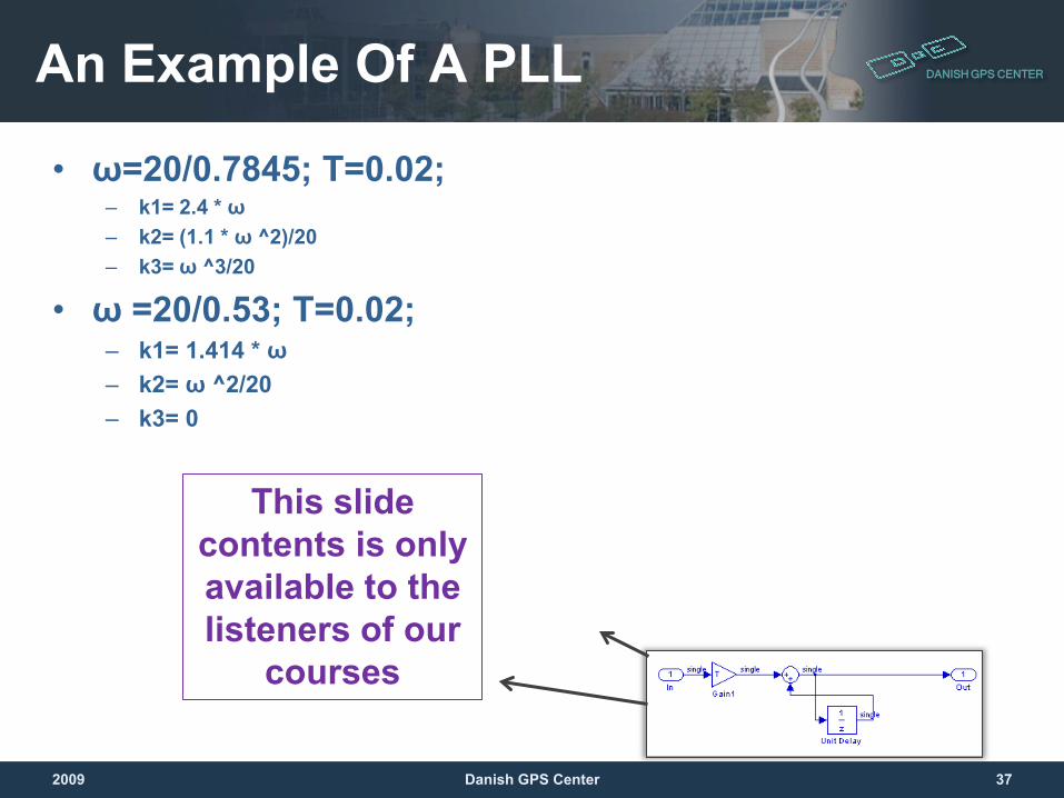
DANISH GPS CENTERAn Example Of A PLL
• ω=20/0.7845; T=0.02; – k1= 2.4 * ω– k2= (1.1 * ω ^2)/20– k3= ω ^3/20
• ω =20/0.53; T=0.02; – k1= 1.414 * ω– k2= ω ^2/20– k3= 0
2009 37Danish GPS Center
This slide contents is only available to the listeners of our
courses
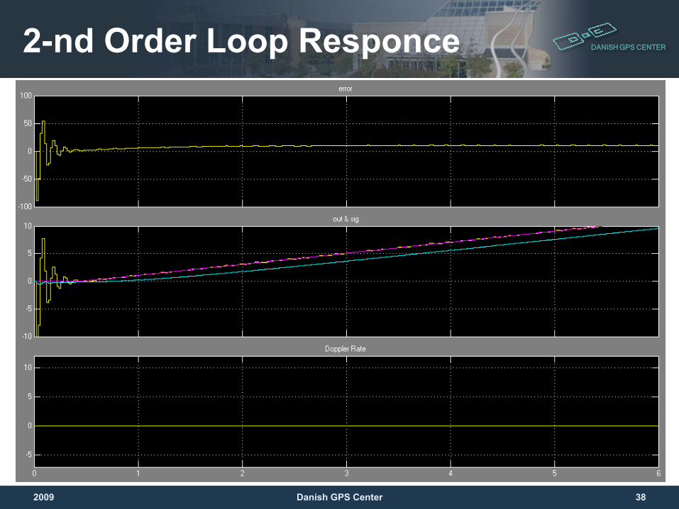
DANISH GPS CENTER2-nd Order Loop Responce
2009 38Danish GPS Center
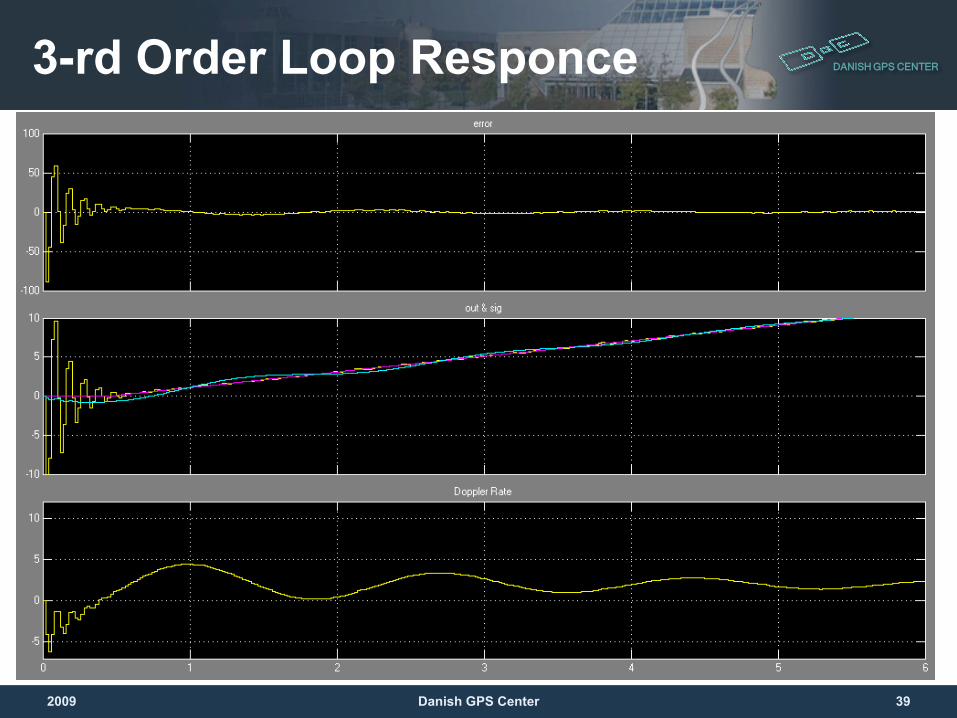
DANISH GPS CENTER3-rd Order Loop Responce
2009 39Danish GPS Center
DANISH GPS CENTER
Questions and Exercises
2009 40Danish GPS Center