Embed Size (px)
Citation preview
ULTRA-CURVE®
Digital Dual-DSP Mainframe
Model DSP 8000
VERSION 1.3 July 1996
Text: Hubert Barth & Uli Behringer
Translation: Mark Cahill Layout: Bettina Liesen
The Information contained in this manual is subject to change withoutnotice. No part of this manual may be reproduced or transmitted in anyform or by any means, electronic or mechanical, including photocopyingand recording of any kind. for any purpose, without the express writtenpermission of Behringer GmbH.
ALL RIGHTS RESERVED © 1996 BEHRINGER GmbH
BEHRINGER Spezielle Studiotechnik GmbH, Hanns-Martin-Schleyer-Str. 36-38, FRG-47877 Willich-Münchheide II, Tel.(0)2154/9206-0 Fax (0)2154/9206-30 © 1996 Behringer GmbH. ULTRA-CURVE and BEHRINGER are registered trade marks of
Behringer GmbH.
SAFETY INSTRUCTIONSCAUTION: To reduce the risk of electrical shock, do not remove the cover
(or back). No user serviceable parts inside: refer servicing toqualified personnel.
WARNING: To reduce the risk of fire or electrical shock, do not expose thisappliance to rain or moisture.
This symbol, wherever it appears, alerts you to the presence of uninsulated dangerous voltage inside the enclosure - voltage thatmay be sufficient to constitute a risk of shock.
This symbol, wherever it appears, alerts you to important operating and maintenance instructions in the accompanying literature.Read the manual.
DETAILED SAFETY INSTRUCTIONS:All the safety and operation instructions should be read before the appliance is operated.
Retain Instructions:
The safety and operating instructions should be retained for future reference.
Heed Warnings:
All warnings on the appliance and in the operating instructions should be adhered to.
Follow Instructions:
All operation and user instructions should be followed.Water and Moisture:
The appliance should not be used near water (e.g. near a bathtub, washbowl, kitchen sink. laundry tub, in a wetbasement, or near a swimming pool etc.).
Ventilation:The appliance should be situated so that its location or position does not interfere with its proper ventilaton. For
example, the appliance should not be situated on a bed, sofa rug, or similar surface that may block the ventilation
openings, or placed in a built-in installation, such as a bookcase or cabinet that may impede the flow of air
through the ventilation openings.
Heat:
The appliance should be situated away from heat sources such as radiators, heat registers, stoves, or other
appliances (including amplifiers) that produce heat.
Power Source:
The appliance should be connected to a power supply only of the type described in the operating instructions or asmarked on the appliance.
Grounding or Polarization:Precautions should be taken so that the grounding or polarization means of an appliance is not defeated.
Power-Cord Protection:
Power supply cords should be routed so that they are not likely to be walked on or pinched by items placed upon
or against them, paying particular attention to cords and plugs, convenience receptacles and the point where they
exit from the appliance.
Cleaning:The appliance should be cleaned only as recommended by the manufacturer.
Non-use Periods:The power cord of the appliance should be unplugged from the outlet when left unused for a long period of time.
Object and Liquid Entry:
Care should be taken so that objects do not fall and liquids are not spilled into the enclosure through openings. Damage Requiring Service:The appliance should be serviced by qualified service personnel when:- The power supply cord or the plug has been damaged: or- Objects have fallen, or liquid has been spilled into the appliance; or- The appliance has been exposed to rain; or- The appliance does not appear to operate normally or exhibits a marked change in performance; or- The appliance has been dropped, or the enclosure damaged.
Servicing:
The user should not attempt to service the appliance beyond that is described in the Operating Instructions. Allother servicing should be referred to qualified service personnel.
WELCOME
Dear Customer,
Welcome to the Behringer ULTRA-CURVE and thankyou for placing your trust in Behringer products. My mostpleasant task is to write this letter to you, because it is the culmination of many months of hard work for ourengineering team. We built in some extra features that will certainly compensate for the extra months it took.Our daily objective is to be focused on you, the musician and sound engineer, and with that focus in mind, itdrives us to reach a goal which is unique, and is the backbone of the Behringer philosophy.
That philosophy is very simple, that you, the customer, are the most important part of the Behringer family. Wewill not accept anything less for you than the highest quality, best specified product, at the lowest price. Thisenables you to express your full creativity without price being a concern.
Due to the thousands of satisfied Behringer users around the world, we are able to demand the highest qualitycomponents industry can offer, at extremely low prices, making the final cost of our products astonishinglylow. Why then, shouldn't we pass the benefit of our good fortune back to you, the musician and soundengineer? This enables you to own the type of quality equipment that previously would have cost very muchmore. It also allows you the confidence that your new equipment uses technology which is leading the way inthe field of audio design.
I would like to thank the following people, whose help on Project ULTRA-CURVE' has made it all possible:
* The existing users of Behringer equipment (whose comments and suggestions have made them the mostimportant members of the Behringer design team),
* Frieder, Ralf and Holger for the ingenious software (Why don't we build in a MIDI dishwasher? There'senough DSP power left!),
* Hartmut and Stefan for the hardware (key-word ‘PCB Revision #981’),* Frank for the fine mechanics (key-word 'Tooling Modification'),* Hubert for the unsurpassed manual,* Mark for the translation into (Irish) English,* Betty for the perfect layout* and all other helpers for their energetic assistance.
We believe a creative musician and sound engineer lies in you and we want to share in your success. Ourproducts are built for people like you -people with a fine ear- and as you have trusted us by buying theBehringer ULTRA-CURVE, we return your trust by welcoming you into the Behringer family.
Thank you and sincerely yours,
BEHRINGER Spezielle Studiotechnik GmbH
Uli Behringer
President
ULTRA-CURVE®
DIGITALDUAL-DSP MAINFRAME
MODEL DSP 8000
1.0 INTRODUCTION 1 - 1
1.1 SHORT INTRODUCTION TO DIGITAL SIGNAL PROCESSING 1 - 1
2.0 THE CONCEPT 2 - 1
2.1 HIGH QUALITY COMPONENTS AND DESIGN 2 - 2
2.1.1 Two Independent Channels 2 - 2
2.1.2 Failsafe Relays 2 - 3
2.2 INPUTS AND OUTPUTS 2 - 3
2.2.1 Analogue Inputs and Outputs 2 - 3
2.2.2 Reference Microphone Input 2 - 3
2.2.3 Digital Input and Output (Option) 2 - 3
2.2.4 MIDI 2 - 3
3.0 BLOCK DIAGRAMS 3 - 1
3.1 HARDWARE 3 - 1
3.2 SOFTWARE 3 - 2
3.2.1 Equalizer Mode 3 - 2
3.2.2 Analyzer Mode 3 - 3
4.0 INSTALLATION 4 - 1
4.1 RACK MOUNTING 4 - 1
4.2 CONNECTORS 4 - 1
4.2.1 Impedances 4 - 1
4.2.2 Unbalanced/Balanced Operation 4 - 1
4.2.3 The Correct Wiring for Balanced Operation 4 - 2
4.3 OPERATION WITH XLR CONNECTORS 4 - 2
4.3.1 Balanced Operation with XLR Connectors 4 - 2
4.3.2 Unbalanced Operation with XLR Connectors 4 - 3
4.3.3 Connecting a Reference Microphone 4 - 4
4.4 OPERATION WITH 1/4" JACK PLUGS 4 - 4
4.4.1 Balanced Operation with 1/4" Jack Plugs 4 - 4
4.4.2 Unbalanced Operation with 1/4" Jack Plugs 4 - 4
4.5 DIGITAL AUDIO CONNECTION PER AES/EBU (Option) 4 - 5
4.6 MIDI CONNECTIONS 4 - 5
4.7 MAINS CONNECTION 4 - 6
4.7.1 Operating Voltage Selector 4 - 6
4.7.2 Safety Fuse Replacement 4 - 6
5.0 CONTROLS 5 - 1
5.1 THE FRONT PANEL LAYOUT OF THE ULTRA-CURVE 5 - 1
5.1.1 Operating Methods and Bypass Mode 5 - 1
5.1.2 Softkeys 5 - 2
5.1.3 The Cursor Keys 5 - 2
5.2 THE BACK PANEL LAYOUT OF THE ULTRA-CURVE 5 - 2
6.0 OPERATION 6 - 1
6.1 GENERAL SETUP 6 - 1
6.2 THE EQUALIZER 6 - 3
6.2.1 Operating the Graphic Equalizer 6 - 3
6.2.2 The Level Meter 6 - 4
6.2.3 The Feedback Destroyer 6 - 5
6.2.4 Delay (Option) 6 - 6
6.2.5 Equalizer Editing 6 - 6
6.2.6 EQ Setup 6 - 9
6.3 REAL TIME ANALYZER (RTA) 6 - 10
6.3.1 Program Administration 6 - 11
6.3.2 Toolbox 6 - 12
6.3.3 Choosing a Source 6 - 12
6.3.4 Decay 6 - 12
6.3.5 RTA Setup 6 - 13
7.0 APPLICATIONS 7 - 1
7.1 USING THE ULTRA-CURVE AS A SUMMING EQ IN A PA. 7 - 1
7.2 USING THE ULTRA-CURVE FOR MONITOR EQ PURPOSES 7 - 3
7.3 USING THE ULTRA-CURVE IN THE RECORDING STUDIO 7 - 4
7.4 THE ULTRA-CURVE AS PART OF A KEYBOARD SETUP 7 - 4
7.5 THE ULTRA-CURVE IN A GUITAR SETUP 7 - 5
7.6 THE ULTRA-CURVE AS AN ADC (AES/EBU Option) 7 - 5
7.7 THE ULTRA-CURVE AS A DELAY UNIT (DELAY Option) 7 - 5
8.0 SPECIFICATIONS 8 - 1
8.1 OPTIONS AND DEVELOPMENTS 8 - 4
8.1.1 Options 8 - 4
8.1.2 Operating Software 8 - 4
8.1.3 Changing the Memory Protect Battery 8 - 4
8.1.4 Under Development 8 - 4
8.2 MIDI IMPLEMENTATION CHART OF THE ULTRA-CURVE 8 - 5
9.0 WARRANTY 9 - 1
1.0 INTRODUCTION
The Behringer ULTRA-CURVE is a fully digital sound processing device based on DSPs, and using 20-bit A/D andD/A converters. The high speed DSPs are capable of performing any process required of them in fractions of asecond, the only element affecting their performance being the software. The enormous flexibility available meansthat the ULTRA-CURVE has a range of features greatly exceeding those found in a conventional analogue graphicequalizer, at a price previously unimaginable. The ULTRA-CURVEs features:
s Digital stereo Mainframe powered by two High-Speed Signal Processorss Superb audio quality and dynamic range backed by high-grade 20-bit Converters with selectable Sampling Rates Open-ended architecture allows for future Software Upgradess Ultra-musical dual 31-band Graphic Equalizer with Auto-Q characteristics for "True Frequency Response"s Shelving filters (low and high pass) with variable slopes High-resolution Real Time Analyzer with peak hold, variable integration, cursor read-out and 10 user-memoriess Automatic Room Equalization using mic input and internal pink/white noise or sine wave generators Additional 6 bands of fully Parametric Equalizer / Notch Filter with up to 1/60th octave precisions Integral fully automatic Feedback Destroyer with intelligent Signal Analyzer for ultra-fast Feedback Suppressions Integral digital Multiband Limiter with variable Threshold controls Integral digital Noise Gate with Behringer's unique IRC (Interactive Ratio Control)s Integral Delay with up to 5 seconds delay time selectable in milliseconds, meter and feet (option)s Ultra-accurate Level Peak Meter with Peak Hold and selectable Reference Levels (+4 dBu / -10 dBV /Dig Max)s Full MIDI parameter and snapshot control (future EQ-design-software allows for total remote control via PC)s 100 User-Memories can be stored under any alphanumeric names Memories backed by a long-life batterys Security Key Password can be installed for user selective RTA- and EQ-memory protection and tamper-proofs EQ- and Analyzer-curves may be copied, compared, added or subtracteds Crossfade feature to fade between two settings and "Stereolink" facility to synchronize both channelss AES/EBU Interface for Digital Inputs and Outputs (option)s Large High-Resolution LCD Graphic Display with high-contrast LED-backlights Servo-balanced Inputs and Outputs with XLR- and jack connectors as standards Relay controlled Hard-Bypass with an Auto-Bypass function during power failure (failsafe relay)
1.1 SHORT INTRODUCTION TO DIGITAL SIGNAL PROCESSING
In order to convert an analogue signal - e.g. music - into a series of digital words, a so-called 'Analogue to DigitalConverter’ or ADC is used. The converter functions by viewing the signal entering it a given number of times over aperiod of time, e.g. 44,100 times per second, giving a rate of 44.1 kHz, and in each case measuring the signalamplitude, and giving it a numerical value. This form of measuring the signal regularly over a period of time is knownas 'sampling', the conversion of the amplitude into a numerical value, quantizing. The two actions together arereferred to as digitizing.In order to carry out the opposite - the conversion of a digitized signal into its original analogue form -a 'Digital toAnalogue Converter' or DAC is used. In both cases the frequency at which the device operates is called the samplingrate. The sampling rate determines the effective audio frequency range. The sampling rate must always be more thantwice the value of the highest frequency to be reproduced. Therefore, the well known CD sampling rate of 44.1 kHz isslightly higher than twice the highest audible frequency of 20 kHz. The accuracy at which quantization takes place isprimarily dependent on the quality of the ADCs and DACs being used.
Introduction 1 -1
The resolution, or size of digital word used (expressed in bits), determines the theoretical Signal/Noise ratio (S/Nratio) the audio system is capable of providing.
The number of bits may be compared to the number of decimal places used in a calculation – the greater thenumber of places, the more accurate the end result. Theoretically, each extra bit of resolution should result inthe S/N ratio increasing by 6 dB. Unfortunately there are a considerable number of other factors to be takeninto account, which hinder the achievement of these theoretical values.
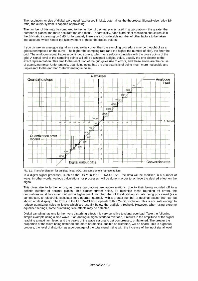
If you picture an analogue signal as a sinusoidal curve, then the sampling procedure may be thought of as agrid superimposed on the curve. The higher the sampling rate (and the higher the number of bits), the finer thegrid. The analogue signal traces a continuous curve, which very seldom coincides with the cross points of thegrid. A signal level at the sampling points will still be assigned a digital value, usually the one closest to theexact representation. This limit to the resolution of the grid gives rise to errors, and these errors are the causeof quantizing noise. Unfortunately, quantizing noise has the characteristic of being much more noticeable andunpleasant to the ear than 'natural' analogue noise.
Fig. 1.1: Transfer diagram for an ideal linear ADC (2's complement representation)
In a digital signal processor, such as the DSPs in the ULTRA-CURVE, the data will be modified in a number ofways, in other words, various calculations, or processes, will be done in order to achieve the desired effect on thesignal.
This gives rise to further errors, as these calculations are approximations, due to their being rounded off to adefined number of decimal places. This causes further noise. To minimize these rounding off errors, thecalculations must be carried out with a higher resolution than that of the digital audio data being processed (as acomparison, an electronic calculator may operate internally with a greater number of decimal places than can beshown on its display). The DSPs in the ULTRA-CURVE operate with a 24 bit resolution. This is accurate enough toreduce quantizing noise to levels which are usually below the audible threshold. However, when using extremeequalizer settings, some quantizing side effects may be detected.
Digital sampling has one further, very disturbing effect: it is very sensitive to signal overload. Take the followingsimple example using a sine wave. If an analogue signal starts to overload, it results in the amplitude of the signalreaching a maximum level, and the peaks of the wave starting to get compressed, or flattened. The greater theproportion of the wave being flattened, the more harmonics, audible as distortion, will be heard. This is a gradualprocess, the level of distortion as a percentage of the total signal rising with the increase of the input signal level.
Introduction 1-2
Digital distortion is quite different, as illustrated by this oversimplified example. If we take the situation where a 4bit word has the positive maximum value of 0111, and add to it the smallest possible value of 0001 (in otherwords, the smallest increase in amplitude possible), the addition of the two results in 1000 - the value of the'negative' maximum. The value is turned on its head, going instantly from positive max to negative max, resultingin the very noticeable onset of extreme signal distortion.
Introduction 1 –3
2.0 THE CONCEPT
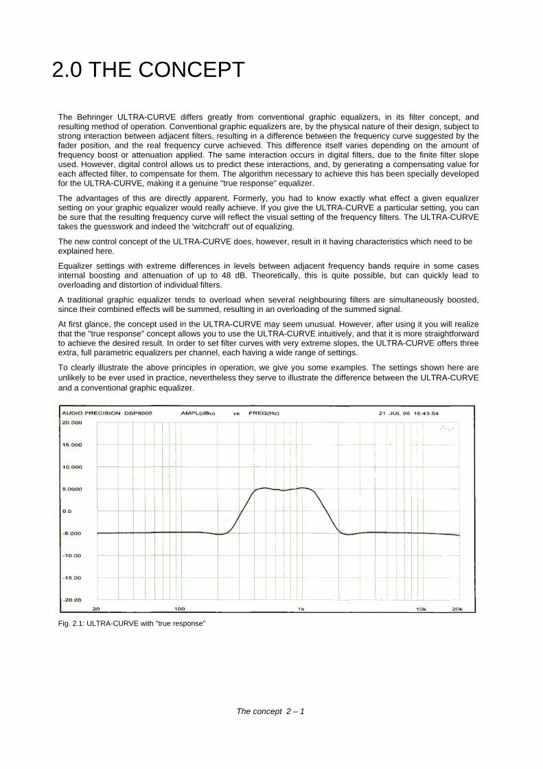
The Behringer ULTRA-CURVE differs greatly from conventional graphic equalizers, in its filter concept, andresulting method of operation. Conventional graphic equalizers are, by the physical nature of their design, subject tostrong interaction between adjacent filters, resulting in a difference between the frequency curve suggested by thefader position, and the real frequency curve achieved. This difference itself varies depending on the amount offrequency boost or attenuation applied. The same interaction occurs in digital filters, due to the finite filter slopeused. However, digital control allows us to predict these interactions, and, by generating a compensating value foreach affected filter, to compensate for them. The algorithm necessary to achieve this has been specially developedfor the ULTRA-CURVE, making it a genuine "true response" equalizer.
The advantages of this are directly apparent. Formerly, you had to know exactly what effect a given equalizersetting on your graphic equalizer would really achieve. If you give the ULTRA-CURVE a particular setting, you canbe sure that the resulting frequency curve will reflect the visual setting of the frequency filters. The ULTRA-CURVEtakes the guesswork and indeed the 'witchcraft' out of equalizing.
The new control concept of the ULTRA-CURVE does, however, result in it having characteristics which need to beexplained here.
Equalizer settings with extreme differences in levels between adjacent frequency bands require in some casesinternal boosting and attenuation of up to 48 dB. Theoretically, this is quite possible, but can quickly lead tooverloading and distortion of individual filters.
A traditional graphic equalizer tends to overload when several neighbouring filters are simultaneously boosted,since their combined effects will be summed, resulting in an overloading of the summed signal.
At first glance, the concept used in the ULTRA-CURVE may seem unusual. However, after using it you will realizethat the "true response" concept allows you to use the ULTRA-CURVE intuitively, and that it is more straightforwardto achieve the desired result. In order to set filter curves with very extreme slopes, the ULTRA-CURVE offers threeextra, full parametric equalizers per channel, each having a wide range of settings.
To clearly illustrate the above principles in operation, we give you some examples. The settings shown here areunlikely to be ever used in practice, nevertheless they serve to illustrate the difference between the ULTRA-CURVEand a conventional graphic equalizer.
Fig. 2.1: ULTRA-CURVE with "true response"
The concept 2 – 1
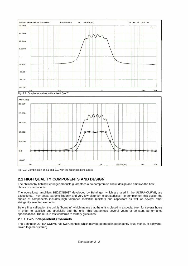
Fig. 2.2: Graphic equalizer with a fixed Q of 7
Fig. 2.3: Combination of 2.1 and 2.2, with the fader positions added
2.1 HIGH QUALITY COMPONENTS AND DESIGNThe philosophy behind Behringer products guarantees a no-compromise circuit design and employs the bestchoice of components.
The operational amplifiers BE027/BE037 developed by Behringer, which are used in the ULTRA-CURVE, areexceptional. They boast extreme linearity and very low distortion characteristics. To complement this design thechoice of components includes high tolerance metalfilm resistors and capacitors as well as several otherstringently selected elements.
Before final calibration the unit is "burnt in", which means that the unit is placed in a special oven for several hoursin order to stabilize and artificially age the unit. This guarantees several years of constant performancespecifications. The burn-in test conforms to military guidelines.
2.1.1 Two Independent ChannelsThe Behringer ULTRA-CURVE has two Channels which may be operated independently (dual mono), or software-linked together (stereo).
The concept 2 –2
2.1.2 Failsafe Relays
Failsafe Relays have been incorporated into the design of the Behringer ULTRA-CURVE, which automatically andsilently bypass the unit in the event of power supply disconnection or failure. These Relays are also active atswitch-on to isolate the ULTRA-CURVE until the power rails have settled, thus preventing the possibility of apotentially damaging switch-on thump.
2.2 INPUTS AND OUTPUTS
2.2.1 Analogue Inputs and Outputs
As standard, the Behringer ULTRA-CURVE is installed with electronically servo-balanced Inputs and Outputs.The new circuit design features automatic hum and noise reduction for balanced signals and thus allows fortrouble-free operation, even at high operating levels. Externally induced mains hum etc. will be effectivelysuppressed.The automatic servo-function recognizes the presence of unbalanced connectors and adjusts the nominal levelinternally to avoid level differences between the Input and Output (correction 6 dB).
2.2.2 Reference Microphone Input
The Reference Microphone Input has a balanced Input Pre-Amplifier which raises the input signal by 20 dB.Additionally, it has 15 Volt Phantom Power. This Phantom Power design also allows the use of microphoneswhich do not require Phantom Power.
2.2.3 Digital Input and Output (Option)
The Digital Input and Output (AES/EBU interface) are non earth balanced. The use of high quality transformersguarantees a noise and hum free signal transfer.
2.2.4 MIDI
The MIDI connectors (IN/OUT/THRU) are standard 5 pin DIN sockets. Signal transfer is potential free via opto-coupler.
The concept 2 - 3
3.0 BLOCK DIAGRAMS
3.1 HARDWARE
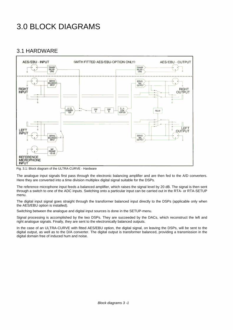
Fig. 3.1: Block diagram of the ULTRA-CURVE - Hardware
The analogue input signals first pass through the electronic balancing amplifier and are then fed to the A/D converters.Here they are converted into a time division multiplex digital signal suitable for the DSPs.
The reference microphone input feeds a balanced amplifier, which raises the signal level by 20 dB. The signal is then sentthrough a switch to one of the ADC inputs. Switching onto a particular input can be carried out in the RTA- or RTA-SETUPmenu.
The digital input signal goes straight through the transformer balanced input directly to the DSPs (applicable only whenthe AES/EBU option is installed).
Switching between the analogue and digital input sources is done in the SETUP-menu.
Signal processing is accomplished by the two DSPs. They are succeeded by the DACs, which reconstruct the left andright analogue signals. Finally, they are sent to the electronically balanced outputs.
In the case of an ULTRA-CURVE with fitted AES/EBU option, the digital signal, on leaving the DSPs, will be sent to thedigital output, as well as to the D/A converter. The digital output is transformer balanced, providing a transmission in thedigital domain free of induced hum and noise.
Block diagrams 3 -1
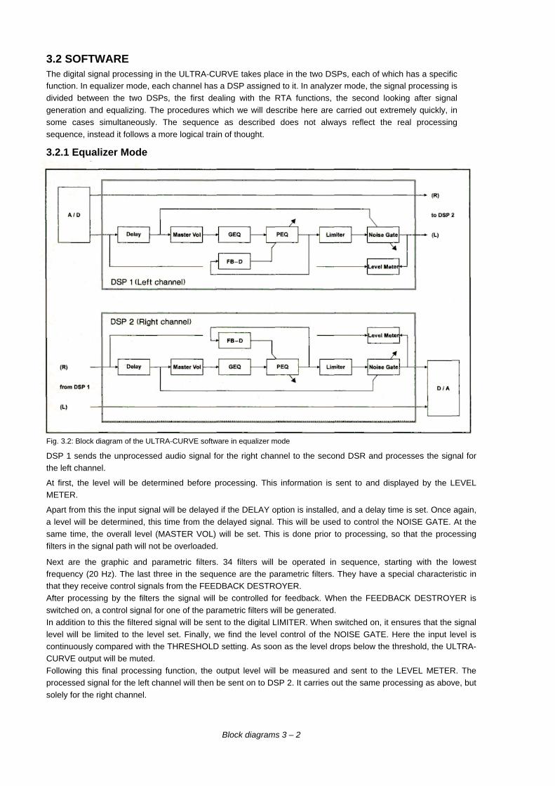
3.2 SOFTWAREThe digital signal processing in the ULTRA-CURVE takes place in the two DSPs, each of which has a specificfunction. In equalizer mode, each channel has a DSP assigned to it. In analyzer mode, the signal processing isdivided between the two DSPs, the first dealing with the RTA functions, the second looking after signalgeneration and equalizing. The procedures which we will describe here are carried out extremely quickly, insome cases simultaneously. The sequence as described does not always reflect the real processingsequence, instead it follows a more logical train of thought.
3.2.1 Equalizer Mode
Fig. 3.2: Block diagram of the ULTRA-CURVE software in equalizer mode
DSP 1 sends the unprocessed audio signal for the right channel to the second DSR and processes the signal forthe left channel.
At first, the level will be determined before processing. This information is sent to and displayed by the LEVELMETER.
Apart from this the input signal will be delayed if the DELAY option is installed, and a delay time is set. Once again,a level will be determined, this time from the delayed signal. This will be used to control the NOISE GATE. At thesame time, the overall level (MASTER VOL) will be set. This is done prior to processing, so that the processingfilters in the signal path will not be overloaded.
Next are the graphic and parametric filters. 34 filters will be operated in sequence, starting with the lowestfrequency (20 Hz). The last three in the sequence are the parametric filters. They have a special characteristic inthat they receive control signals from the FEEDBACK DESTROYER.After processing by the filters the signal will be controlled for feedback. When the FEEDBACK DESTROYER isswitched on, a control signal for one of the parametric filters will be generated.In addition to this the filtered signal will be sent to the digital LIMITER. When switched on, it ensures that the signallevel will be limited to the level set. Finally, we find the level control of the NOISE GATE. Here the input level iscontinuously compared with the THRESHOLD setting. As soon as the level drops below the threshold, the ULTRA-CURVE output will be muted.Following this final processing function, the output level will be measured and sent to the LEVEL METER. Theprocessed signal for the left channel will then be sent on to DSP 2. It carries out the same processing as above, butsolely for the right channel.
Block diagrams 3 – 2
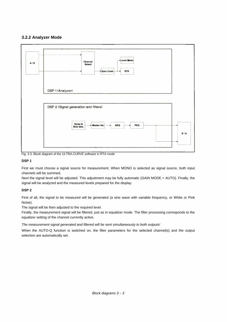
3.2.2 Analyzer Mode
Fig. 3.3: Block diagram of the ULTRA-CURVE software in RTA mode
DSP 1
First we must choose a signal source for measurement. When MONO is selected as signal source, both inputchannels will be summed,Next the signal level will be adjusted. This adjustment may be fully automatic (GAIN MODE = AUTO). Finally, thesignal will be analyzed and the measured levels prepared for the display.
DSP 2
First of all, the signal to be measured will be generated (a sine wave with variable frequency, or White or PinkNoise).The signal will be then adjusted to the required level.Finally, the measurement signal will be filtered, just as in equalizer mode. The filter processing corresponds to theequalizer setting of the channel currently active.
The measurement signal generated and filtered will be sent simultaneously to both outputs!
When the AUTO-Q function is switched on, the filter parameters for the selected channel(s) and the outputselection are automatically set.
Block diagrams 3 – 3
4.0 INSTALLATION
Your Behringer ULTRA-CURVE was carefully packed in the factory and the packaging was designed toprotect the unit from rough handling. Nevertheless, we recommend that you carefully examine thepackaging and its contents for any signs of physical damage, which may have occurred in transit.
If the unit is damaged, please do not return it to us, but notify your dealer and the shipping companyimmediately, otherwise claims for damage or replacement may not be granted. Shipping claims must bemade by the consignee.
4.1 RACK MOUNTINGThe Behringer ULTRA-CURVE fits into two standard rack units of space (3 1/2"). Please allow at least anadditional 4" depth for the connectors on the back panel. Be sure that there is enough air space around theunit for cooling and please do not place the ULTRA-CURVE on high temperature devices such as poweramplifiers etc. to avoid overheating.
4.2 CONNECTORSThe ULTRA-CURVE can be installed using either XLR or standard 1/4" Jacks. Although the inputs andoutputs are fully balanced, the automatic servo-function allows them to operate with unbalancedsources/loads.
4.2.1 Impedances
The input has an impedance of 40 kOhms and can be driven by most input sources. If a device's outputrequires a load of 600 Ohms (provided with most output transformers), a 600 Ohm resistor should be tiedacross pins 2 and 3 on the input connector.The ULTRA-CURVE´S outputs are electronically balanced and have an output impedance of 40 Ohms.When driving transformer coupled loads, it may be necessary to create a 600 Ohm source impedance. Forthis purpose, install two 287 Ohm resistors (tolerance: 1%) in series with pins 2 and 3.
4.2.2 Unbalanced/Balanced Operation
90% of all mistakes in audio installations can be attributed to incorrect and defective audio connections! Inorder to utilize the Behringer ULTRA-CURVE to its full potential, please pay special attention to thefollowing section.For better understanding, the technical difference between unbalanced and balanced systems must beclarified:
The unbalanced system
Unbalanced operation is characterized by a single conductor shielded cable with the center conductorcarrying the signal and the shield at ground.
The balanced system
A balanced operation is defined as a two conductor shielded cable, where each of the two centerconductors carry the signal but of opposite phase. They have equal but inverted potential differences fromthat of ground.
Installation 4 –1
The advantage of the balanced system is based on the effect that the differential amplifier in a subsequent devicesuppresses all equal phased noise which has been induced during its transmission down the cable link. However,the original signal will be amplified and retain all its original integrity.
In this way, audio signals can be transmitted without interference or loss across long distances.
Balanced or unbalanced systems require different wiring. Please read the next section carefully and pay closeattention to thecorrect wiring requirements of the units in the audio chain.
4.2.3 The Correct Wiring for Balanced OperationIf the unit preceding the ULTRA-CURVE uses output balancing, we recommend that you use balanced audioconnections. This will avoid interference such as mains hum etc.
For maximum hum rejection, you should avoid common grounding, which means, grounding the ULTRA-CURVE'Sinput and output.
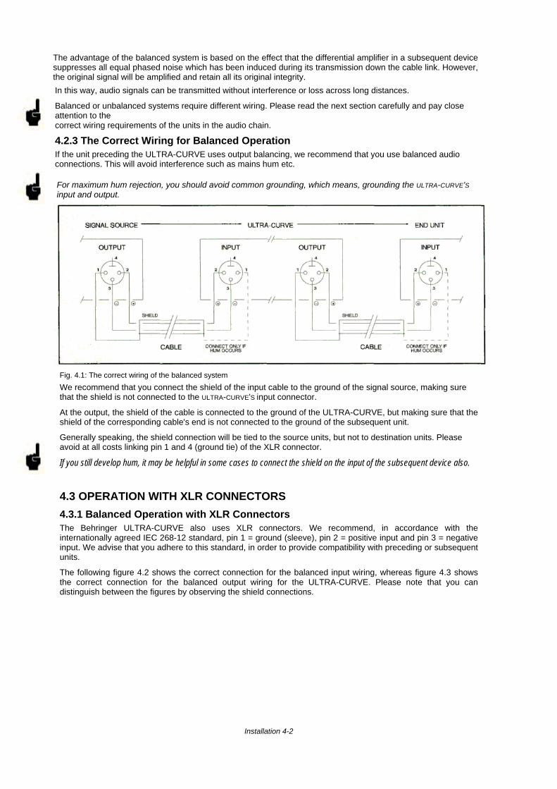
Fig. 4.1: The correct wiring of the balanced system
We recommend that you connect the shield of the input cable to the ground of the signal source, making surethat the shield is not connected to the ULTRA-CURVE'S input connector.
At the output, the shield of the cable is connected to the ground of the ULTRA-CURVE, but making sure that theshield of the corresponding cable's end is not connected to the ground of the subsequent unit.
Generally speaking, the shield connection will be tied to the source units, but not to destination units. Pleaseavoid at all costs linking pin 1 and 4 (ground tie) of the XLR connector.
If you still develop hum, it may be helpful in some cases to connect the shield on the input of the subsequent device also.
4.3 OPERATION WITH XLR CONNECTORS
4.3.1 Balanced Operation with XLR ConnectorsThe Behringer ULTRA-CURVE also uses XLR connectors. We recommend, in accordance with theinternationally agreed IEC 268-12 standard, pin 1 = ground (sleeve), pin 2 = positive input and pin 3 = negativeinput. We advise that you adhere to this standard, in order to provide compatibility with preceding or subsequentunits.
The following figure 4.2 shows the correct connection for the balanced input wiring, whereas figure 4.3 showsthe correct connection for the balanced output wiring for the ULTRA-CURVE. Please note that you candistinguish between the figures by observing the shield connections.
Installation 4-2
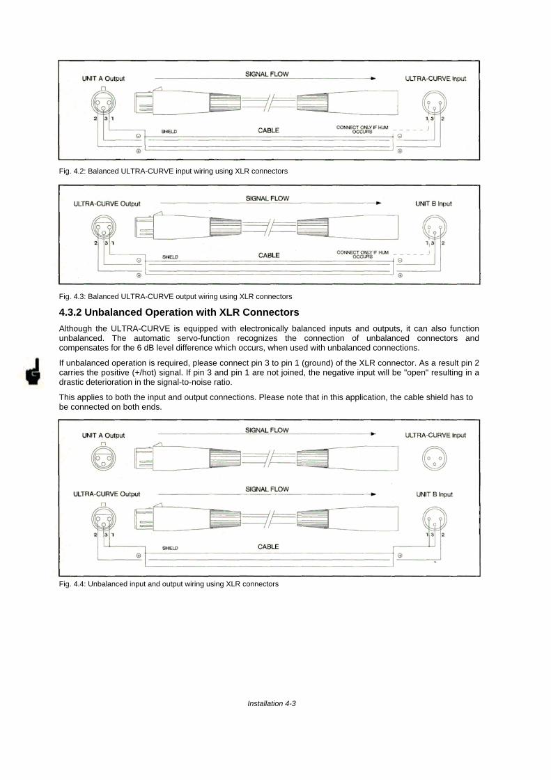
Fig. 4.2: Balanced ULTRA-CURVE input wiring using XLR connectors
Fig. 4.3: Balanced ULTRA-CURVE output wiring using XLR connectors
4.3.2 Unbalanced Operation with XLR Connectors
Although the ULTRA-CURVE is equipped with electronically balanced inputs and outputs, it can also functionunbalanced. The automatic servo-function recognizes the connection of unbalanced connectors andcompensates for the 6 dB level difference which occurs, when used with unbalanced connections.
If unbalanced operation is required, please connect pin 3 to pin 1 (ground) of the XLR connector. As a result pin 2carries the positive (+/hot) signal. If pin 3 and pin 1 are not joined, the negative input will be "open" resulting in adrastic deterioration in the signal-to-noise ratio.
This applies to both the input and output connections. Please note that in this application, the cable shield has tobe connected on both ends.
Fig. 4.4: Unbalanced input and output wiring using XLR connectors
Installation 4-3
4.3.3 Connecting a Reference Microphone
A Reference Microphone should be connected to the MIC INPUT on the rear panel of the ULTRA CURVE. Ideally,a microphone manufactured specifically for reference/measurement purposes should be used. If such amicrophone is not available, a suitable alternative is the use of a good quality condenser microphone, using anomni-directional pick-up pattern. (The 15 Volt phantom power supply of the ULTRA-CURVE can be used to powersuch microphones - check your microphone's handbook to be sure that it is able to work with this power supply.)As a last resort, microphones with a cardioid (uni-directional) characteristic can be used, providing they have afairly linear frequency response. If you are using such a microphone, the following points should be observed:1. Sound approaching the microphone from the sides will have a 'coloured' frequency response, as the directionalresponse of the microphone is frequency dependent.2. When using microphones with a 'proximity effect', which most uni-directional microphones have, remember thatsound sources close to the microphone will be picked up with a boosted low frequency response.
4.4 OPERATION WITH 1/4" JACK PLUGS
The Behringer ULTRA-CURVE, except its MIC INPUT, can also be used with standard 1/4" Jack plugs. Pleaserefer to the following sections for correct wiring:
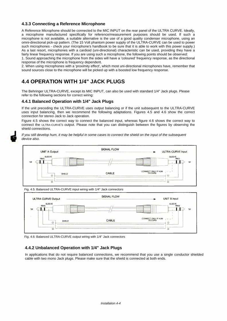
4.4.1 Balanced Operation with 1/4" Jack Plugs
If the unit preceding the ULTRA-CURVE uses output balancing or if the unit subsequent to the ULTRA-CURVEuses input balancing, then we recommend the following adaptations. Figures 4.5 and 4.6 show the correctconnection for stereo Jack to Jack operation.Figure 4.5 shows the correct way to connect the balanced input, whereas figure 4.6 shows the correct way toconnect the ULTRA-CURVE'S output. Please note that you can distinguish between the figures by observing theshield connections.
If you still develop hum, it may be helpful in some cases to connect the shield on the input of the subsequentdevice also.
Fig. 4.5: Balanced ULTRA-CURVE input wiring with 1/4" Jack connectors
Fig. 4.6: Balanced ULTRA-CURVE output wiring with 1/4" Jack connectors
4.4.2 Unbalanced Operation with 1/4" Jack Plugs
In applications that do not require balanced connections, we recommend that you use a single conductor shieldedcable with two mono Jack plugs. Please make sure that the shield is connected at both ends.
Installation 4-4
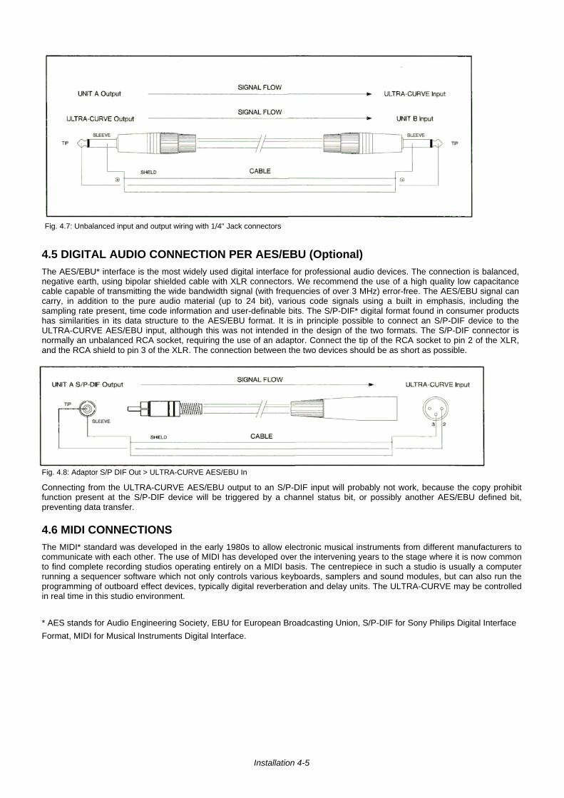
Fig. 4.7: Unbalanced input and output wiring with 1/4" Jack connectors
4.5 DIGITAL AUDIO CONNECTION PER AES/EBU (Optional)The AES/EBU* interface is the most widely used digital interface for professional audio devices. The connection is balanced,negative earth, using bipolar shielded cable with XLR connectors. We recommend the use of a high quality low capacitancecable capable of transmitting the wide bandwidth signal (with frequencies of over 3 MHz) error-free. The AES/EBU signal cancarry, in addition to the pure audio material (up to 24 bit), various code signals using a built in emphasis, including thesampling rate present, time code information and user-definable bits. The S/P-DIF* digital format found in consumer productshas similarities in its data structure to the AES/EBU format. It is in principle possible to connect an S/P-DIF device to theULTRA-CURVE AES/EBU input, although this was not intended in the design of the two formats. The S/P-DIF connector isnormally an unbalanced RCA socket, requiring the use of an adaptor. Connect the tip of the RCA socket to pin 2 of the XLR,and the RCA shield to pin 3 of the XLR. The connection between the two devices should be as short as possible.
Fig. 4.8: Adaptor S/P DIF Out > ULTRA-CURVE AES/EBU In
Connecting from the ULTRA-CURVE AES/EBU output to an S/P-DIF input will probably not work, because the copy prohibitfunction present at the S/P-DIF device will be triggered by a channel status bit, or possibly another AES/EBU defined bit,preventing data transfer.
4.6 MIDI CONNECTIONSThe MIDI* standard was developed in the early 1980s to allow electronic musical instruments from different manufacturers tocommunicate with each other. The use of MIDI has developed over the intervening years to the stage where it is now commonto find complete recording studios operating entirely on a MIDI basis. The centrepiece in such a studio is usually a computerrunning a sequencer software which not only controls various keyboards, samplers and sound modules, but can also run theprogramming of outboard effect devices, typically digital reverberation and delay units. The ULTRA-CURVE may be controlledin real time in this studio environment.
* AES stands for Audio Engineering Society, EBU for European Broadcasting Union, S/P-DIF for Sony Philips Digital Interface
Format, MIDI for Musical Instruments Digital Interface.
Installation 4-5
The MIDI connnectors found on the rear panel are of the universally-used 5 pin DIN type. You require suitable MIDI cables toconnect the ULTRA-CURVE to other MIDI devices. Normally complete cables will be purchased for this use, you can of coursemake your own, using a high quality cable with two cores and shielding (like microphone cable), with as connectors two good180 degree DIN plugs. Pin 2 (center) is connected to the cable's shield, pins 4 and 5 (left and right next to 2) carry the twocores, pins 1 and 3 are not used. MIDI cables should have a maximum length not exceeding 45 feet.
MIDI IN: Receives MIDI data. The input channel will be chosen in the SETUP menu. Here you control:Program change commands to select the 100 equalizer memory positions. Controller data, under the control numbers 64 -127. Controller 64 is used to control the lowest fader of the left channel, controller 65 the next fader, and so on up tocontroller 94. Controller 95 controls the master fader. Controllers 96 - 127 have the corresponding functions for the rightchannel, controller 127 being responsible for the right master fader,
MIDI THRU: The MIDI THRU socket accesses the incoming MIDI signal, allowing several ULTRA-CURVE units to beserially connected.
MIDI OUT: Has no function as yet, but may be required for use by future software updates.
You'll find the ULTRA-CURVE`S MIDI Implementation Chart in chapter 8.2. A software program to run on a PC, enablingconvenient control of several ULTRA-CURVES, is currently under development.
4.7 MAINS CONNECTIONThe mains connection of the ULTRA-CURVE is made by using a mains cable and a standard IEC receptacle. Itmeets all of the international safety certification requirements.
Please make sure that all units have a proper ground connection. For your own safety, it is advisable not toremove the ground connection within the units or at the supply, or fail to make this connection at all. The audioground of the ULTRA-CURVE is internally capacitor de-coupled. to isolate it from the supply earth. It is thereforenot advantegeous to attempt ground loop problem solving using this method.
4.7.1 Operating Voltage Selector
Before you switch on the unit, check that it is configured to match your AC mains voltage requirements. If it doesnot comply, then it is necessary to switch the operating voltage to the correct supply requirements BEFOREturning on the unit, otherwise the unit could be severely damaged. You will find this combined fuse holder/voltageselector at the back, adjacent to the IEC receptacle.
Please note that the AC voltage selection is defined by the position of the fuse holder. If you intend to change theoperating voltage, remove the fuse holder and twist it by 180 degrees before you reinsert it. Matching the twomarkers monitors the selected voltage.
4.7.2 Safety Fuse Replacement
A safety fuse protects the unit from serious defects. If the fuse blows, this is a warning sign and always indicatesthat the circuit is overloaded. The fault must always be repaired before the fuse is replaced.
If the safety fuse is faulty and needs replacing after the unit is repaired, please make sure that you replace it onlywith the identical type and rating. NEVER use fuses of different ratings or cover faulty fuses with aluminium foil.This can cause fire and electric shocks and will endanger your life and the lives of others.
For 200-240 Volts the fuse rating is 160 mA slow-blow and 315 mA slow-blow for mains voltages of 100-120Volts.
Installation 4-6

5.0 CONTROLS
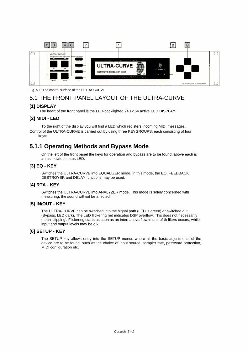
Fig. 5.1: The control surface of the ULTRA-CURVE
5.1 THE FRONT PANEL LAYOUT OF THE ULTRA-CURVE[1] DISPLAY
The heart of the front panel is the LED-backlighted 240 x 64 active LCD DISPLAY.
[2] MIDI - LED
To the right of the display you will find a LED which registers incoming MIDI messages.Control of the ULTRA-CURVE is carried out by using three KEYGROUPS, each consisting of four
keys:
5.1.1 Operating Methods and Bypass ModeOn the left of the front panel the keys for operation and bypass are to be found, above each isan associated status LED.
[3] EQ - KEY
Switches the ULTRA-CURVE into EQUALIZER mode. In this mode, the EQ, FEEDBACKDESTROYER and DELAY functions may be used.
[4] RTA - KEY
Switches the ULTRA-CURVE into ANALYZER mode. This mode is solely concerned withmeasuring, the sound will not be affected!
[5] IN/OUT - KEY
The ULTRA-CURVE can be switched into the signal path (LED is green) or switched out(Bypass, LED dark). The LED flickering red indicates DSP overflow. This does not necessarilymean ‘clipping’. Flickering starts as soon as an internal overflow in one of th filters occurs, whileinput and output levels may be o.k.
[6] SETUP - KEY
The SETUP key allows entry into the SETUP menus where all the basic adjustments of thedevice are to be found, such as the choice of input source, sampler rate, password protection,MIDI configuration etc.
Controls 5 –1
5.1.2 Softkeys
[7] KEYS A, B, C, DTo the left of the display four 'SOFTKEYS', labelled A, B, C and D respectively, are to be found arrangedvertically. Their functions can be defined by the user software and displayed to the immediate right of each key bythe appropriate PICTOGRAM in the display.Each pictogram and its associated functions will be comprehensively explained in chapter 6. You will find functiondiagrams for both EQ and RTA mode as well as a list of all pictograms used next to the back cover.
5.1.3 The Cursor KeysTo the right of the display the
[8] CURSOR KEYSare to be found. These are used:
1.) to select individual filter frequencies, and the master fader in EQUALIZER mode (horizontal)2.) to adjust the value of each selected frequency (vertical)3.) to position the measurement cursor in ANALYZER mode (horizontal)4.) in both operating modes, to choose the program position (vertical)5.) to select a field in the SETUP menu (horizontal and vertical)
In each case pressing on the opposite key while holding the key being used will accelerate the operation beingcarried out.
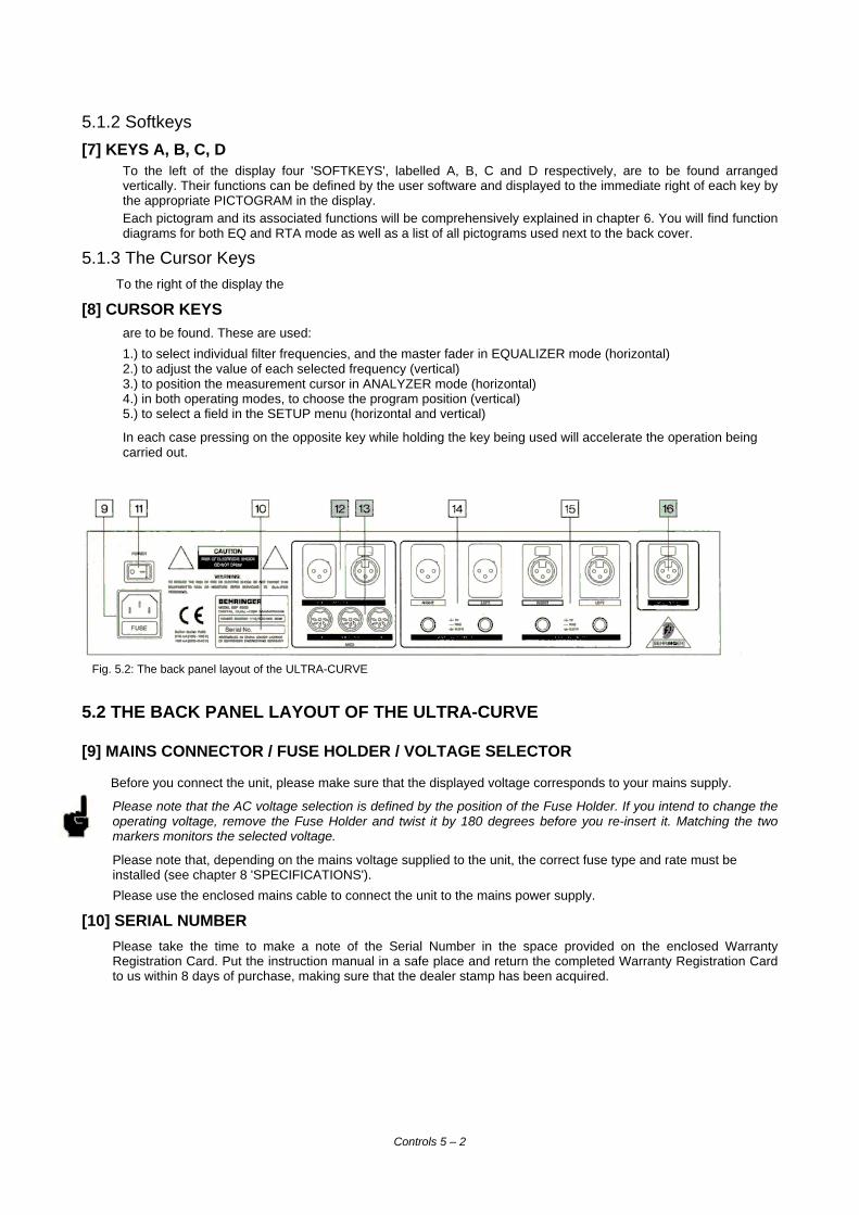
Fig. 5.2: The back panel layout of the ULTRA-CURVE
5.2 THE BACK PANEL LAYOUT OF THE ULTRA-CURVE
[9] MAINS CONNECTOR / FUSE HOLDER / VOLTAGE SELECTOR
Before you connect the unit, please make sure that the displayed voltage corresponds to your mains supply.
Please note that the AC voltage selection is defined by the position of the Fuse Holder. If you intend to change theoperating voltage, remove the Fuse Holder and twist it by 180 degrees before you re-insert it. Matching the twomarkers monitors the selected voltage.
Please note that, depending on the mains voltage supplied to the unit, the correct fuse type and rate must beinstalled (see chapter 8 'SPECIFICATIONS').
Please use the enclosed mains cable to connect the unit to the mains power supply.
[10] SERIAL NUMBER
Please take the time to make a note of the Serial Number in the space provided on the enclosed WarrantyRegistration Card. Put the instruction manual in a safe place and return the completed Warranty Registration Cardto us within 8 days of purchase, making sure that the dealer stamp has been acquired.
Controls 5 – 2
[11] MAINS SWITCH
The Mains Switch is to be found above the mains socket.
[12] AES/EBU IN and AES/EBU OUT
These are the ULTRA-CURVE´s Digital Input and Output (optional).
[13] MIDI OUT / THROUGH / IN
These are the ULTRA-CURVE´s MIDI connectors.
[14] ANALOG OUTPUTS
These are the ULTRA-CURVE´s Analogue Outputs.
[15] ANALOG INPUTS
These are the ULTRA-CURVE´s Analogue Inputs.
[16] MIC INPUT
This is the Input socket for the Reference Microphone.
Controls 5 - 3
6.0 OPERATION
The Behringer ULTRA-CURVE is a flexible, universally applicable sound processing- and measurement device, whoseoperations may be divided into two basic areas. Signal Processor (Equalizer, EQ), or Real Time Analyzer (RTA). For thisreason, you always operate in either EQ or RTA mode. Simultaneous operation of both is not possible! When theULTRA-CURVE is switched from one mode to the other, the outputs will be briefly muted.
6.1 GENERAL SETUPThe SETUP-Menu consists of three windows. Having the EQ or RTA mode active will determine which window is openedon going into SETUP These windows will be referred to as the EQ and RTA windows. Pressing the SETUP key oncemore will show the third window, which has basic functions shared by, and affecting both operating modes. The basicconfiguration will be determined in this window, which will be referred to as the Configuration Window. The other windowscan only be reached from here by leaving the SETUP menu by pressing either the EQ or RTA key, and then re-pressingto enter the relevant window. The EQ and RTA windows will be explained in chapters 6.2.5 and 6.3.5 respectively. Thefollowing deals solely with the Configuration Window.
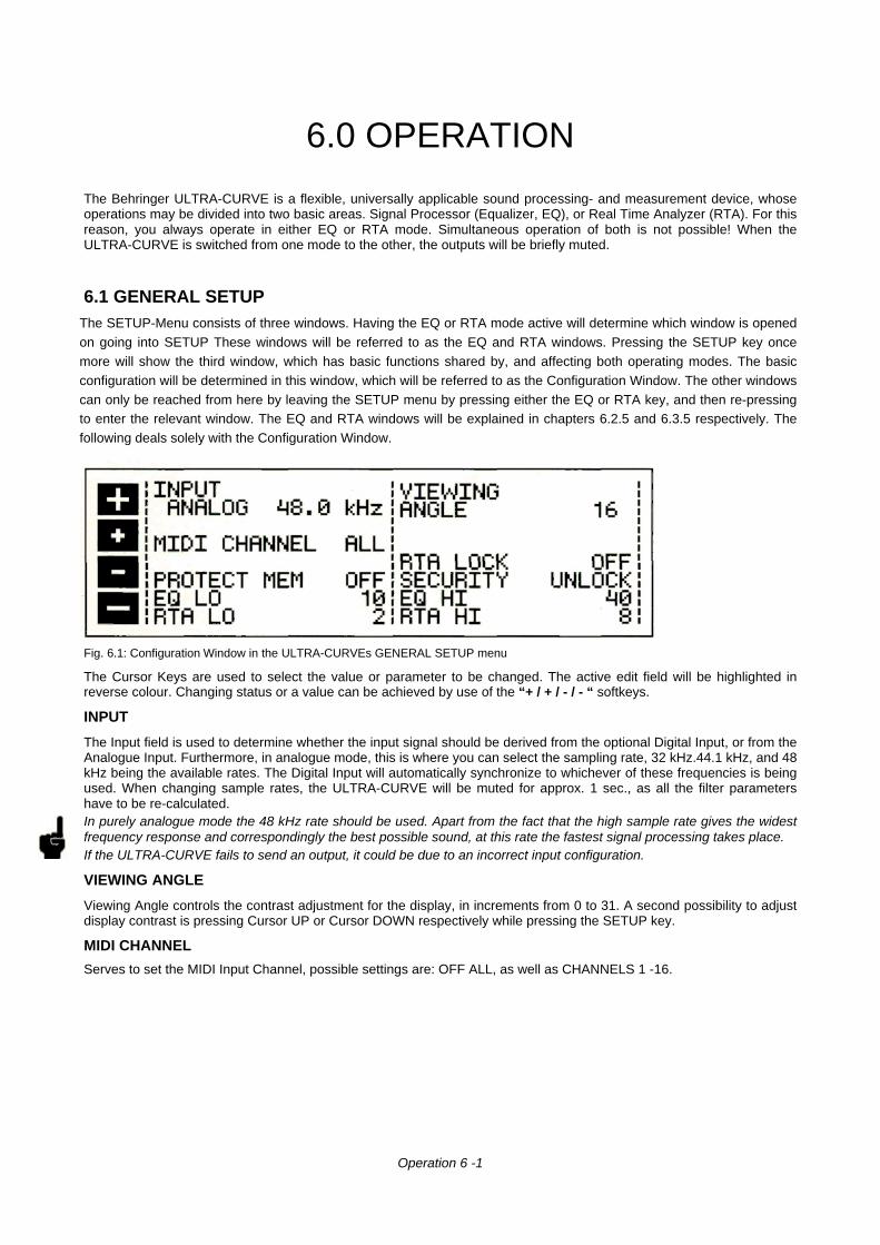
Fig. 6.1: Configuration Window in the ULTRA-CURVEs GENERAL SETUP menu
The Cursor Keys are used to select the value or parameter to be changed. The active edit field will be highlighted inreverse colour. Changing status or a value can be achieved by use of the “+ / + / - / - “ softkeys.
INPUT
The Input field is used to determine whether the input signal should be derived from the optional Digital Input, or from theAnalogue Input. Furthermore, in analogue mode, this is where you can select the sampling rate, 32 kHz.44.1 kHz, and 48kHz being the available rates. The Digital Input will automatically synchronize to whichever of these frequencies is beingused. When changing sample rates, the ULTRA-CURVE will be muted for approx. 1 sec., as all the filter parametershave to be re-calculated.In purely analogue mode the 48 kHz rate should be used. Apart from the fact that the high sample rate gives the widestfrequency response and correspondingly the best possible sound, at this rate the fastest signal processing takes place.If the ULTRA-CURVE fails to send an output, it could be due to an incorrect input configuration.
VIEWING ANGLE
Viewing Angle controls the contrast adjustment for the display, in increments from 0 to 31. A second possibility to adjustdisplay contrast is pressing Cursor UP or Cursor DOWN respectively while pressing the SETUP key.
MIDI CHANNEL
Serves to set the MIDI Input Channel, possible settings are: OFF ALL, as well as CHANNELS 1 -16.
Operation 6 -1
RTA LOCK
When RTA lock is switched on, it is not possible to enter RTA mode. This is designed to prevent unauthorized oraccidental selection of this mode. RTA LOCK should only be de-activated when the ULTRA-CURVE is to be usedspecifically to analyze sound, or if it is to be used in conjunction with another ULTRA-CURVE operating as anequalizer solely for analysis purposes. (Think of the consequences of the situation where you are using the ULTRA-CURVE as a P.A. equalizer, and somebody, by accident, presses the RTA key. This could even, in the worst case,result in the concert sound which you had so carefully equalized being replaced by the Pink Noise of the analyzer, andthis at the full power rating of your system!)
SECURITY
The SECURITY function offers effective protection against unauthorized use of the ULTRA-CURVE. UNLOCK means,that all functions may be accessed, with the exception of the programs which are secured under PROTECTMEMORY. LOCK prevents any of the adjustment parameters on the device being accessed, the only exceptionsbeing the DISPLAY of the present equalizer setting, plus the input and output level with the LEVEL METER. The onlyother way to make changes is via MIDI. In order to use the SECURITY function, a PASSWORD must be entered,which is done using the cursor keys and the softkeys. The softkeys are used to select the letter or symbol to be used,and they have the following functions:
A = “OK” confirms entry of the password and immediately activates the LOCK status.
B = “ç” and C = “è” and move the cursor left and right within the PASSWORD.
D = “CLEAR” erases any characters which may have already been entered.
To abolish the LOCK condition: go into the SETUP menu. The relevant PASSWORD field is immediately accessed,and the PASSWORD may be re-entered. This causes the ULTRA-CURVE to return to the UNLOCK status. If thedevice is locked without entering the PASSWORD, simply enter OK to UNLOCK.
DO NOT FORGET THE PASSWORD! If this happens, there is only one way to remove it: You must open the casingof the ULTRA-CURVE, and take the battery out for a short while. After replacing it, and switching back on, the originalfactory presets will be re-loaded. Warning! Doing this means you lose all your programs. AND void the warranty!
PROTECT MEM
The PROTECT MEMORY function switches the write protect for the program memory on and off You might use aPASSWORD in this case, too.
EQ LO / EQ HIThe two functions EQ LO and EQ HI determine the area of program memory which will be protected by the PROTECTMEMORY function. EQ LO determines the lowest, EQ HI the highest program number of the protected area.Switching OFF means the PROTECT MEMORY function is de-activated only for the equalizer.
RTA LO / RTA HI
The two functions operate identically to EQ LO and EQ HI, except they determine the protection of the RTA programs.
All the SETUP settings are stored when switching off the ULTRA-CURVE, and remain unchanged until you re-editthem.
Operation 6 - 2
6.2 THE EQUALIZER
Upon switching on the ULTRA-CURVE you will be presented either the main EQUALIZER (EQ), or ANALYZER (RTA)window. By pressing the EQ key, you switch from RTA- into EQ mode.
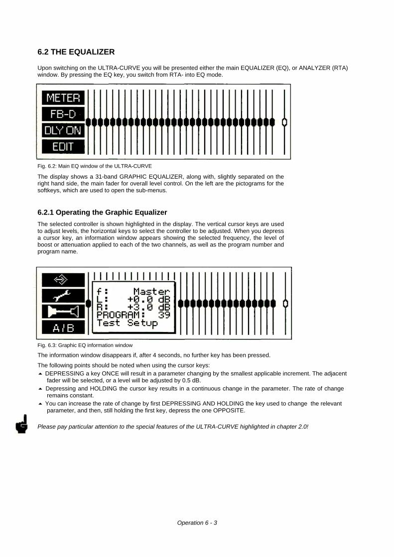
Fig. 6.2: Main EQ window of the ULTRA-CURVE
The display shows a 31-band GRAPHIC EQUALIZER, along with, slightly separated on theright hand side, the main fader for overall level control. On the left are the pictograms for thesoftkeys, which are used to open the sub-menus.
6.2.1 Operating the Graphic Equalizer
The selected controller is shown highlighted in the display. The vertical cursor keys are usedto adjust levels, the horizontal keys to select the controller to be adjusted. When you depressa cursor key, an information window appears showing the selected frequency, the level ofboost or attenuation applied to each of the two channels, as well as the program number andprogram name.
Fig. 6.3: Graphic EQ information window
The information window disappears if, after 4 seconds, no further key has been pressed.
The following points should be noted when using the cursor keys:5 DEPRESSING a key ONCE will result in a parameter changing by the smallest applicable increment. The adjacent
fader will be selected, or a level will be adjusted by 0.5 dB.5 Depressing and HOLDING the cursor key results in a continuous change in the parameter. The rate of change
remains constant.5 You can increase the rate of change by first DEPRESSING AND HOLDING the key used to change the relevant
parameter, and then, still holding the first key, depress the one OPPOSITE.
Please pay particular attention to the special features of the ULTRA-CURVE highlighted in chapter 2.0!
Operation 6 - 3
6.2.2 The Level Meter
By pressing softkey A “METER” you leave the main EQ window and access the menu to display levels.
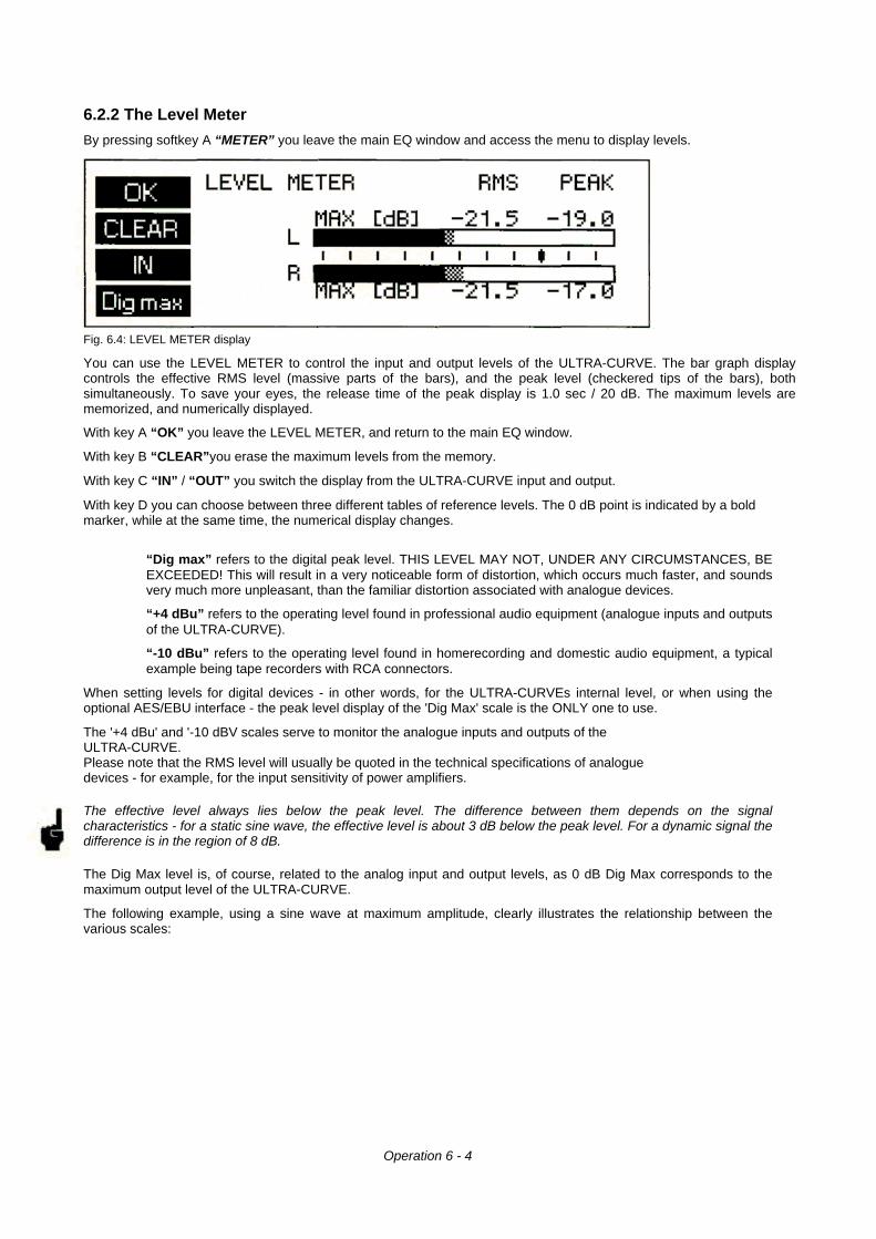
Fig. 6.4: LEVEL METER display
You can use the LEVEL METER to control the input and output levels of the ULTRA-CURVE. The bar graph displaycontrols the effective RMS level (massive parts of the bars), and the peak level (checkered tips of the bars), bothsimultaneously. To save your eyes, the release time of the peak display is 1.0 sec / 20 dB. The maximum levels arememorized, and numerically displayed.
With key A “OK” you leave the LEVEL METER, and return to the main EQ window.
With key B “CLEAR”you erase the maximum levels from the memory.
With key C “IN” / “OUT” you switch the display from the ULTRA-CURVE input and output.
With key D you can choose between three different tables of reference levels. The 0 dB point is indicated by a boldmarker, while at the same time, the numerical display changes.
“Dig max” refers to the digital peak level. THIS LEVEL MAY NOT, UNDER ANY CIRCUMSTANCES, BEEXCEEDED! This will result in a very noticeable form of distortion, which occurs much faster, and soundsvery much more unpleasant, than the familiar distortion associated with analogue devices.
“+4 dBu” refers to the operating level found in professional audio equipment (analogue inputs and outputsof the ULTRA-CURVE).
“-10 dBu” refers to the operating level found in homerecording and domestic audio equipment, a typicalexample being tape recorders with RCA connectors.
When setting levels for digital devices - in other words, for the ULTRA-CURVEs internal level, or when using theoptional AES/EBU interface - the peak level display of the 'Dig Max' scale is the ONLY one to use.
The '+4 dBu' and '-10 dBV scales serve to monitor the analogue inputs and outputs of theULTRA-CURVE.Please note that the RMS level will usually be quoted in the technical specifications of analoguedevices - for example, for the input sensitivity of power amplifiers.
The effective level always lies below the peak level. The difference between them depends on the signalcharacteristics - for a static sine wave, the effective level is about 3 dB below the peak level. For a dynamic signal thedifference is in the region of 8 dB.
The Dig Max level is, of course, related to the analog input and output levels, as 0 dB Dig Max corresponds to themaximum output level of the ULTRA-CURVE.
The following example, using a sine wave at maximum amplitude, clearly illustrates the relationship between thevarious scales:
Operation 6 - 4
As can be seen from the above table, the ULTRA-CURVEs maximum analogue output level is +10 dBu, or +8 dBV.
The ULTRA-CURVEs analogue inputs can handle signals of up to +21 dBu, but it is important to remember that, incase of such high input levels, the digital LIMITER may operate if the level in the EQUALIZER is not appropriatelylowered. Please refer to the operation of the digital LIMITER explained in section 6.2.6.
6.2.3 The Feedback Destroyer
By pressing softkey B “FB-D” you leave the main EQ window and go into the FEEDBACK DESTROYER menu.
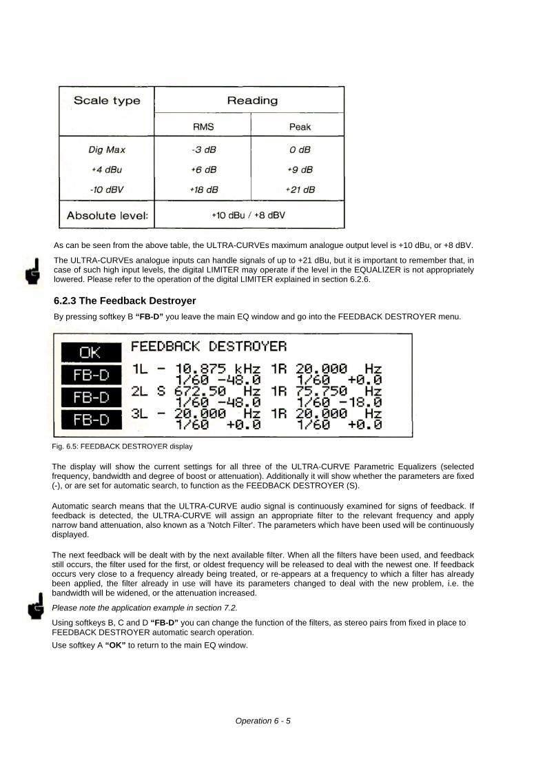
Fig. 6.5: FEEDBACK DESTROYER display
The display will show the current settings for all three of the ULTRA-CURVE Parametric Equalizers (selectedfrequency, bandwidth and degree of boost or attenuation). Additionally it will show whether the parameters are fixed(-), or are set for automatic search, to function as the FEEDBACK DESTROYER (S).
Automatic search means that the ULTRA-CURVE audio signal is continuously examined for signs of feedback. Iffeedback is detected, the ULTRA-CURVE will assign an appropriate filter to the relevant frequency and applynarrow band attenuation, also known as a 'Notch Filter'. The parameters which have been used will be continuouslydisplayed.
The next feedback will be dealt with by the next available filter. When all the filters have been used, and feedbackstill occurs, the filter used for the first, or oldest frequency will be released to deal with the newest one. If feedbackoccurs very close to a frequency already being treated, or re-appears at a frequency to which a filter has alreadybeen applied, the filter already in use will have its parameters changed to deal with the new problem, i.e. thebandwidth will be widened, or the attenuation increased.
Please note the application example in section 7.2.
Using softkeys B, C and D “FB-D” you can change the function of the filters, as stereo pairs from fixed in place toFEEDBACK DESTROYER automatic search operation.
Use softkey A “OK” to return to the main EQ window.
Operation 6 - 5
6.2.4 Delay (Option)
By pressing softkey C “DLY OFF” / “DLY ON” the built-in signal DELAY can be switched on or off. The display showsthe current status:
“DLY OFF” = switched off,
“DLY ON” = switched on, signal will be delayed by the numerical value present.
You can set the DELAY time in the EQ SETUP menu (see chapter 6.2.6). Among its many uses, it can be used tocompensate fortime path differences between two sets of loudspeakers set at different distances to the listener.
See chapter 7.7 for an application example.
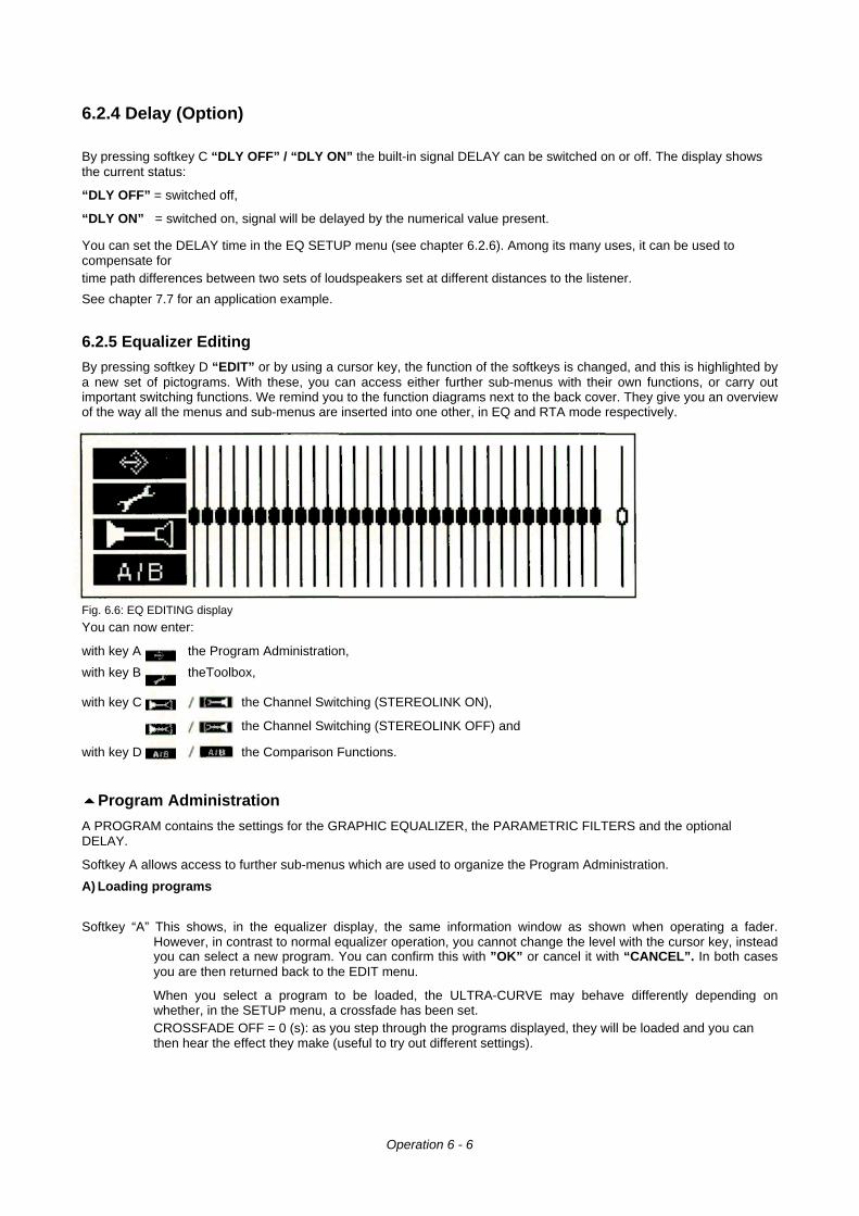
6.2.5 Equalizer Editing
By pressing softkey D “EDIT” or by using a cursor key, the function of the softkeys is changed, and this is highlighted bya new set of pictograms. With these, you can access either further sub-menus with their own functions, or carry outimportant switching functions. We remind you to the function diagrams next to the back cover. They give you an overviewof the way all the menus and sub-menus are inserted into one other, in EQ and RTA mode respectively.
Fig. 6.6: EQ EDITING display
You can now enter:
with key A the Program Administration,
with key B theToolbox,
with key C the Channel Switching (STEREOLINK ON),
the Channel Switching (STEREOLINK OFF) and
with key D the Comparison Functions.
55Program Administration
A PROGRAM contains the settings for the GRAPHIC EQUALIZER, the PARAMETRIC FILTERS and the optionalDELAY.
Softkey A allows access to further sub-menus which are used to organize the Program Administration.
A) Loading programs
Softkey “A” This shows, in the equalizer display, the same information window as shown when operating a fader.However, in contrast to normal equalizer operation, you cannot change the level with the cursor key, insteadyou can select a new program. You can confirm this with ”OK” or cancel it with “CANCEL”. In both casesyou are then returned back to the EDIT menu.
When you select a program to be loaded, the ULTRA-CURVE may behave differently depending onwhether, in the SETUP menu, a crossfade has been set.CROSSFADE OFF = 0 (s): as you step through the programs displayed, they will be loaded and you canthen hear the effect they make (useful to try out different settings).
Operation 6 - 6
CROSSFADE ON -- 1 - 15 (s): the chosen program will be executed only upon confirmation. “OK” starts the crossfadebetween old and new programs (this is best used when you know the specific program which you wish to use). In thissub-menu you can change channels at any time with the C softkey.
Using softkey D “CLEAR” you can reset all the current ULTRA-CURVE settings - the Graphic Equalizer, the ParametricFilters (also in FEEDBACK DESTROYER mode) and the DELAY - to zero. You will first be presented with the question"CLEAR PROGRAM IN MEMORY?" which can be confirmed with “OK”. By using “CANCEL” you can stop at this pointand leave the settings as they are.
We recommend that you make use of this feature whenever you have something completely new to do and have to starteverything from scratch. This way you can carry on without the danger that maybe an old FEEDBACK DESTROYERsetting is in the place which could cause problems. In any case it is the quickest and most convenient way to reset allthe parametric filters.
B) Saving programs
Softkey B The procedure of saving a program is analogous to that of loading one. The memory location isselected with the vertical cursor keys, is confirmed with “OK” and cancelled with “CANCEL” If a programlocation is already occupied, the warning OVERWRITE PROGRAM? will appear. Pressing ”OK” once moreallows you to confirm the save. “CANCEL” means it does not take place, and the program already in placeremains undisturbed.
C) Naming programs
Softkey C “ABC...” Important to note here is that program names can have a maximum of 12characters. You will see a window in the equalizer display, showing the available characters. Choose the character yourequire with the cursor key, which is to be found in the part of the name field highlighted by blinking. You can change positionusing the arrows keys “çç” / “èè”,.”CLEAR” removes all characters. Having completed the name you wish to use, pressing“OK” returns you to the EDIT menu.
When naming, remember it is always the program resident in memory which you are naming. If you want to re-name a stored program,you must first load it into memory.
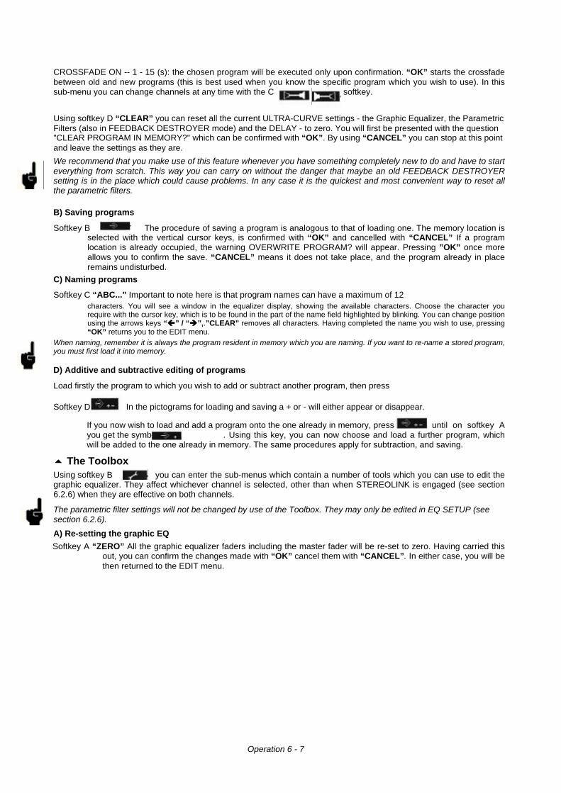
D) Additive and subtractive editing of programs
Load firstly the program to which you wish to add or subtract another program, then press
Softkey D In the pictograms for loading and saving a + or - will either appear or disappear.
If you now wish to load and add a program onto the one already in memory, press until on softkey Ayou get the symbol . Using this key, you can now choose and load a further program, whichwill be added to the one already in memory. The same procedures apply for subtraction, and saving.
55 The ToolboxUsing softkey B you can enter the sub-menus which contain a number of tools which you can use to edit thegraphic equalizer. They affect whichever channel is selected, other than when STEREOLINK is engaged (see section6.2.6) when they are effective on both channels.
The parametric filter settings will not be changed by use of the Toolbox. They may only be edited in EQ SETUP (seesection 6.2.6).
A) Re-setting the graphic EQ
Softkey A “ZERO” All the graphic equalizer faders including the master fader will be re-set to zero. Having carried thisout, you can confirm the changes made with “OK” cancel them with “CANCEL”. In either case, you will bethen returned to the EDIT menu.
Operation 6 - 7
With softkey C or respectively, you can check the status of each channel on the display,before confirming the changes as mentioned above. While doing this, you cannot make any other changes.
B) Inverting the current settingsSoftkey B “INTERVENT” This causes the levels of all the graphic faders, with the exception of the master
fader, to invert. I.e. a value of +5 becomes -5, -2 becomes +2 etc. This edit can be confirmed asabove.
C) Copyina the current setting to the other channel
Softkey C / / The current setting will be copied to the other channel. Confirmation as above.
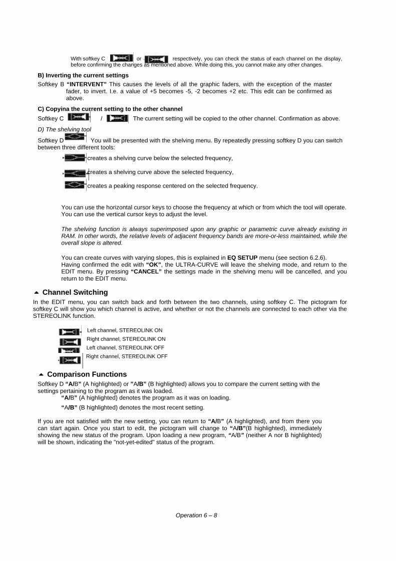
D) The shelving tool
Softkey D You will be presented with the shelving menu. By repeatedly pressing softkey D you can switchbetween three different tools:
creates a shelving curve below the selected frequency,
creates a shelving curve above the selected frequency,
creates a peaking response centered on the selected frequency.
You can use the horizontal cursor keys to choose the frequency at which or from which the tool will operate.You can use the vertical cursor keys to adjust the level.
The shelving function is always superimposed upon any graphic or parametric curve already existing inRAM. In other words, the relative levels of adjacent frequency bands are more-or-less maintained, while theoverall slope is altered.
You can create curves with varying slopes, this is explained in EQ SETUP menu (see section 6.2.6).Having confirmed the edit with “OK”, the ULTRA-CURVE will leave the shelving mode, and return to theEDIT menu. By pressing “CANCEL” the settings made in the shelving menu will be cancelled, and youreturn to the EDIT menu.
55 Channel SwitchingIn the EDIT menu, you can switch back and forth between the two channels, using softkey C. The pictogram forsoftkey C will show you which channel is active, and whether or not the channels are connected to each other via theSTEREOLINK function.
Left channel, STEREOLINK ON
Right channel, STEREOLINK ON
Left channel, STEREOLINK OFF
Right channel, STEREOLINK OFF
55 Comparison FunctionsSoftkey D “A/B” (A highlighted) or ”A/B” (B highlighted) allows you to compare the current setting with thesettings pertaining to the program as it was loaded.
“A/B” (A highlighted) denotes the program as it was on loading.
“A/B” (B highlighted) denotes the most recent setting.
If you are not satisfied with the new setting, you can return to “A/B” (A highlighted), and from there youcan start again. Once you start to edit, the pictogram will change to “A/B”(B highlighted), immediatelyshowing the new status of the program. Upon loading a new program, “A/B” (neither A nor B highlighted)will be shown, indicating the "not-yet-edited" status of the program.
Operation 6 – 8
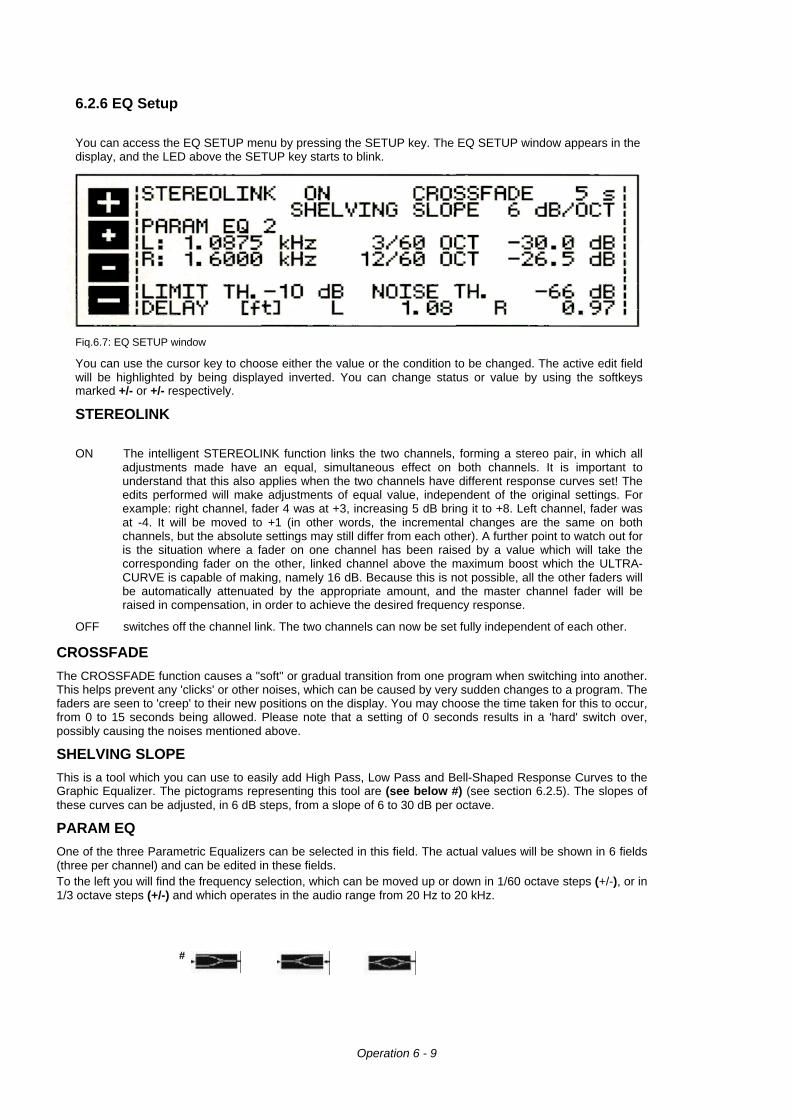
6.2.6 EQ Setup
You can access the EQ SETUP menu by pressing the SETUP key. The EQ SETUP window appears in thedisplay, and the LED above the SETUP key starts to blink.
Fiq.6.7: EQ SETUP window
You can use the cursor key to choose either the value or the condition to be changed. The active edit fieldwill be highlighted by being displayed inverted. You can change status or value by using the softkeysmarked +/- or +/- respectively.
STEREOLINK
ON The intelligent STEREOLINK function links the two channels, forming a stereo pair, in which alladjustments made have an equal, simultaneous effect on both channels. It is important tounderstand that this also applies when the two channels have different response curves set! Theedits performed will make adjustments of equal value, independent of the original settings. Forexample: right channel, fader 4 was at +3, increasing 5 dB bring it to +8. Left channel, fader wasat -4. It will be moved to +1 (in other words, the incremental changes are the same on bothchannels, but the absolute settings may still differ from each other). A further point to watch out foris the situation where a fader on one channel has been raised by a value which will take thecorresponding fader on the other, linked channel above the maximum boost which the ULTRA-CURVE is capable of making, namely 16 dB. Because this is not possible, all the other faders willbe automatically attenuated by the appropriate amount, and the master channel fader will beraised in compensation, in order to achieve the desired frequency response.
OFF switches off the channel link. The two channels can now be set fully independent of each other.
CROSSFADE
The CROSSFADE function causes a "soft" or gradual transition from one program when switching into another.This helps prevent any 'clicks' or other noises, which can be caused by very sudden changes to a program. Thefaders are seen to 'creep' to their new positions on the display. You may choose the time taken for this to occur,from 0 to 15 seconds being allowed. Please note that a setting of 0 seconds results in a 'hard' switch over,possibly causing the noises mentioned above.
SHELVING SLOPE
This is a tool which you can use to easily add High Pass, Low Pass and Bell-Shaped Response Curves to theGraphic Equalizer. The pictograms representing this tool are (see below #) (see section 6.2.5). The slopes ofthese curves can be adjusted, in 6 dB steps, from a slope of 6 to 30 dB per octave.
PARAM EQ
One of the three Parametric Equalizers can be selected in this field. The actual values will be shown in 6 fields(three per channel) and can be edited in these fields.To the left you will find the frequency selection, which can be moved up or down in 1/60 octave steps (+/-), or in1/3 octave steps (+/-) and which operates in the audio range from 20 Hz to 20 kHz.
#
Operation 6 - 9
In the middle the BANDWIDTH can be set, adjustable in 1/60 octave steps from the narrowest width of 1/60octave up to 2 octaves as the widest possible setting.To the right is the LEVEL, adjustable in 0.5 dB steps from +16 to -48 dB.Above L = left channel. Below R = right channel.
Be careful boosting very narrow bandwidths! This can rapidly lead to audible distortion and, worse still, couldcause damage to your loudspeakers - even before you hear the distortion!
LIMIT THRESHOLD
The ULTRA-CURVE has an integrated DIGITAL LIMITER to protect against overloading and resultingdistortion. Its Attack Time is zero - in other words, it reacts 'in advance'. The operating Threshold of theLIMITER can be set, in 1 dB steps, anywhere from 0 dB down to -48 dB. The levels given in dB are relative tothe maximum output signal (Dig Max) of the ULTRA-CURVE (0 dB Dig Max equates to +10 dBu or +8 dBV).Additionally, you can deactivate the LIMITER by choosing the setting OFF.
NOISE THRESHOLD
You can mute noise (e.g. from a mixing desk, or keyboards) which might appear during program pauses, byusing the built-in NOISE GATE function. As soon as the signal level is lower than the Threshold you will haveset, the ULTRA-CURVE´S outputs will be muted. The Threshold may be anywhere from -96 dB to -48 dB, thescale again referring to the digital maximum.
DELAY (OPTION)
The DELAY can be adjusted in 10 millisecond steps to a maximum value of 5 seconds, and this can be appliedindependently to each channel. An interesting alternative is to apply this as a measure of metres or feet perchannel. The distances entered will be automatically calculated as time delays.
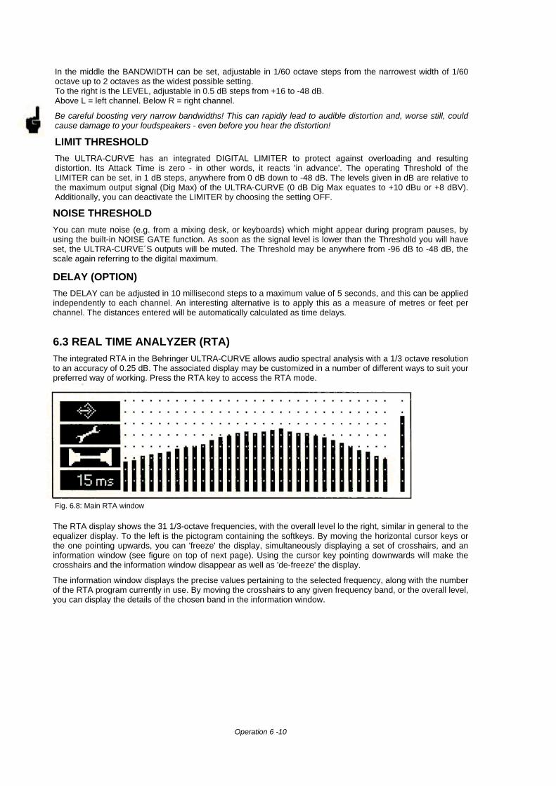
6.3 REAL TIME ANALYZER (RTA)The integrated RTA in the Behringer ULTRA-CURVE allows audio spectral analysis with a 1/3 octave resolutionto an accuracy of 0.25 dB. The associated display may be customized in a number of different ways to suit yourpreferred way of working. Press the RTA key to access the RTA mode.
Fig. 6.8: Main RTA window
The RTA display shows the 31 1/3-octave frequencies, with the overall level lo the right, similar in general to theequalizer display. To the left is the pictogram containing the softkeys. By moving the horizontal cursor keys orthe one pointing upwards, you can 'freeze' the display, simultaneously displaying a set of crosshairs, and aninformation window (see figure on top of next page). Using the cursor key pointing downwards will make thecrosshairs and the information window disappear as well as 'de-freeze' the display.
The information window displays the precise values pertaining to the selected frequency, along with the numberof the RTA program currently in use. By moving the crosshairs to any given frequency band, or the overall level,you can display the details of the chosen band in the information window.
Operation 6 -10
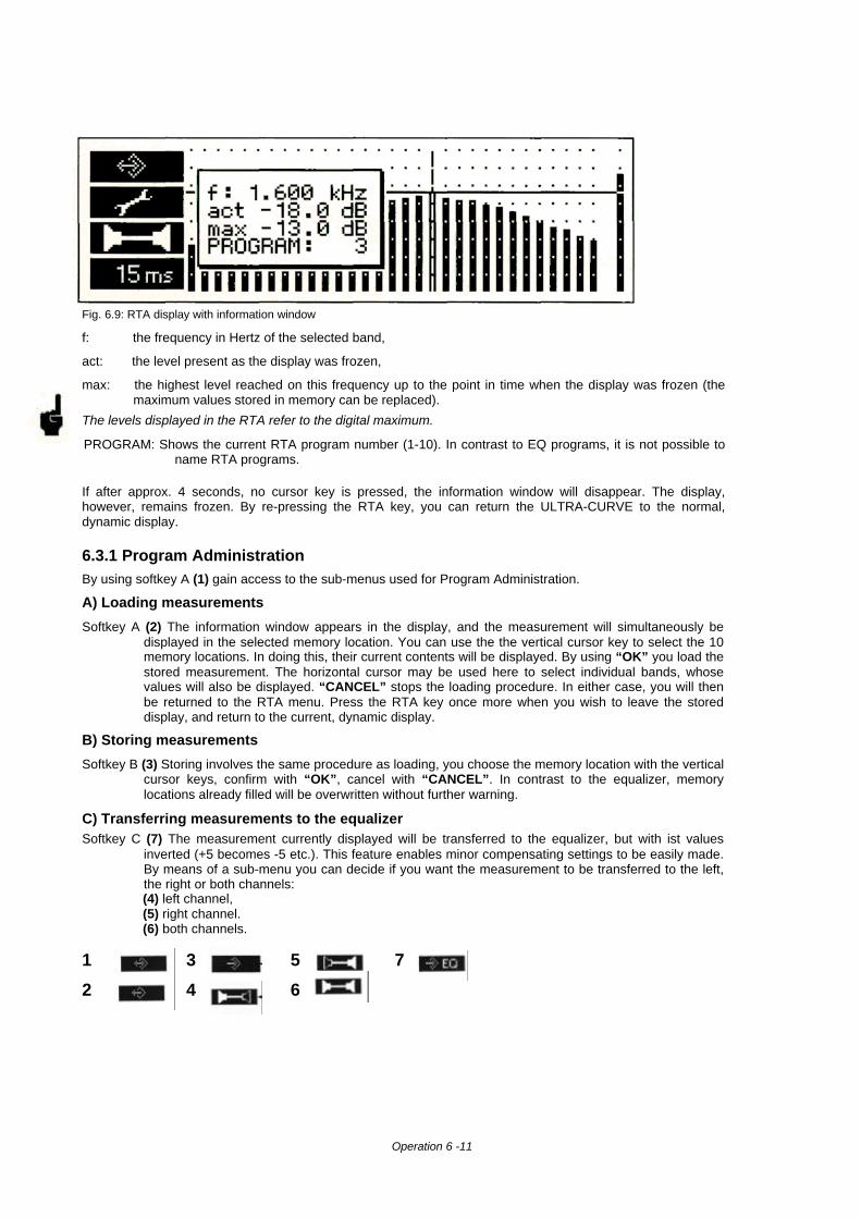
Fig. 6.9: RTA display with information window
f: the frequency in Hertz of the selected band,
act: the level present as the display was frozen,
max: the highest level reached on this frequency up to the point in time when the display was frozen (themaximum values stored in memory can be replaced).
The levels displayed in the RTA refer to the digital maximum.
PROGRAM: Shows the current RTA program number (1-10). In contrast to EQ programs, it is not possible toname RTA programs.
If after approx. 4 seconds, no cursor key is pressed, the information window will disappear. The display,however, remains frozen. By re-pressing the RTA key, you can return the ULTRA-CURVE to the normal,dynamic display.
6.3.1 Program AdministrationBy using softkey A (1) gain access to the sub-menus used for Program Administration.
A) Loading measurements
Softkey A (2) The information window appears in the display, and the measurement will simultaneously bedisplayed in the selected memory location. You can use the the vertical cursor key to select the 10memory locations. In doing this, their current contents will be displayed. By using “OK” you load thestored measurement. The horizontal cursor may be used here to select individual bands, whosevalues will also be displayed. “CANCEL” stops the loading procedure. In either case, you will thenbe returned to the RTA menu. Press the RTA key once more when you wish to leave the storeddisplay, and return to the current, dynamic display.
B) Storing measurements
Softkey B (3) Storing involves the same procedure as loading, you choose the memory location with the verticalcursor keys, confirm with “OK”, cancel with “CANCEL”. In contrast to the equalizer, memorylocations already filled will be overwritten without further warning.
C) Transferring measurements to the equalizerSoftkey C (7) The measurement currently displayed will be transferred to the equalizer, but with ist values
inverted (+5 becomes -5 etc.). This feature enables minor compensating settings to be easily made.By means of a sub-menu you can decide if you want the measurement to be transferred to the left,the right or both channels:(4) left channel,(5) right channel.(6) both channels.
1 3 5 7
2 4 6
Operation 6 -11
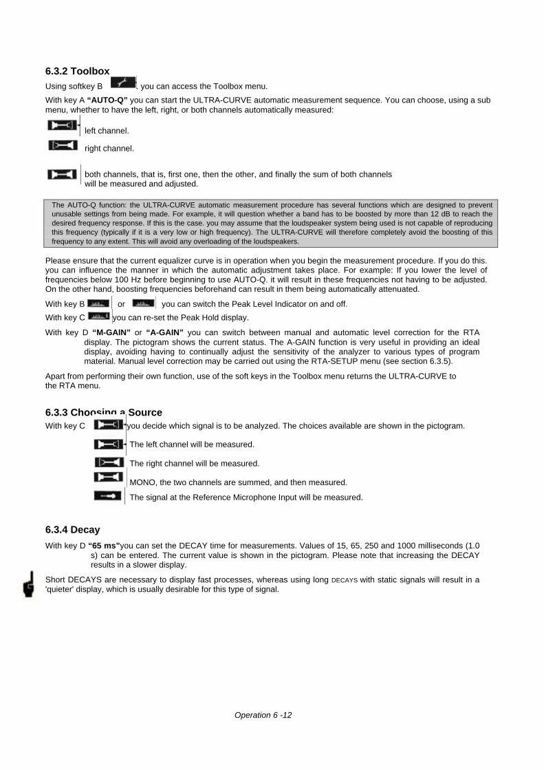
6.3.2 ToolboxUsing softkey B . you can access the Toolbox menu.
With key A “AUTO-Q” you can start the ULTRA-CURVE automatic measurement sequence. You can choose, using a submenu, whether to have the left, right, or both channels automatically measured:
left channel.
right channel.
both channels, that is, first one, then the other, and finally the sum of both channelswill be measured and adjusted.
The AUTO-Q function: the ULTRA-CURVE automatic measurement procedure has several functions which are designed to preventunusable settings from being made. For example, it will question whether a band has to be boosted by more than 12 dB to reach thedesired frequency response. If this is the case. you may assume that the loudspeaker system being used is not capable of reproducingthis frequency (typically if it is a very low or high frequency). The ULTRA-CURVE will therefore completely avoid the boosting of thisfrequency to any extent. This will avoid any overloading of the loudspeakers.
Please ensure that the current equalizer curve is in operation when you begin the measurement procedure. If you do this.you can influence the manner in which the automatic adjustment takes place. For example: If you lower the level offrequencies below 100 Hz before beginning to use AUTO-Q. it will result in these frequencies not having to be adjusted.On the other hand, boosting frequencies beforehand can result in them being automatically attenuated.
With key B or you can switch the Peak Level Indicator on and off.
With key C you can re-set the Peak Hold display.
With key D “M-GAIN” or “A-GAIN” you can switch between manual and automatic level correction for the RTAdisplay. The pictogram shows the current status. The A-GAIN function is very useful in providing an idealdisplay, avoiding having to continually adjust the sensitivity of the analyzer to various types of programmaterial. Manual level correction may be carried out using the RTA-SETUP menu (see section 6.3.5).
Apart from performing their own function, use of the soft keys in the Toolbox menu returns the ULTRA-CURVE tothe RTA menu.
6.3.3 Choosing a SourceWith key C you decide which signal is to be analyzed. The choices available are shown in the pictogram.
The left channel will be measured.
The right channel will be measured.
MONO, the two channels are summed, and then measured.
The signal at the Reference Microphone Input will be measured.
6.3.4 Decay
With key D “65 ms”you can set the DECAY time for measurements. Values of 15, 65, 250 and 1000 milliseconds (1.0s) can be entered. The current value is shown in the pictogram. Please note that increasing the DECAYresults in a slower display.
Short DECAYS are necessary to display fast processes, whereas using long DECAYS with static signals will result in a'quieter' display, which is usually desirable for this type of signal.
Operation 6 -12
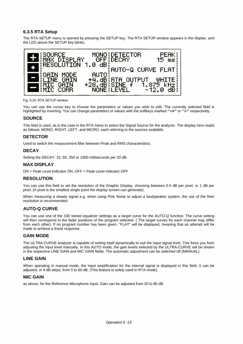
6.3.5 RTA SetupThe RTA SETUP menu is opened by pressing the SETUP key. The RTA SETUP window appears in the displav. andthe LED above the SETUP key blinks.
Fig. 6.10: RTA SETUP window
You can use the cursor key to choose the parameters or values you wish to edit. The currently selected field ishighlighted by inverting. You can change parameters or values with the softkeys marked “+/+” or “-/-“ respectively.
SOURCE
This field is used, as is the case in the RTA menu to select the Signal Source for the analyzer. The display here readsas follows: MONO. RIGHT, LEFT, and MICRO, each referring to the sources available.
DETECTORUsed to switch the measurement filter between Peak and RMS characteristics.
DECAYSetting the DECAY: 15, 65, 250 or 1000 milliseconds per 20 dB.
MAX DISPLAYON = Peak Level Indicator ON, OFF = Peak Level Indicator OFF
RESOLUTION
You can use this field to set the resolution of the Graphic Display, choosing between 0.5 dB per pixel, or 1 dB perpixel. (A pixel is the smallest single point the display screen can generate).
When measuring a steady signal e.g. when using Pink Noise to adjust a loudspeaker system, the use of the finerresolution is recommended.
AUTO-Q CURVE
You can use one of the 100 stored equalizer settings as a target curve for the AUTO-Q function. The curve settingwill then correspond to the fader positions of the program selected. ( The target curves for each channel may differfrom each other). If no program number has been given, "FLAT" will be displayed, meaning that an attempt will bemade to achieve a linear response.
GAIN MODE
The ULTRA-CURVE analyzer is capable of setting itself dynamically to suit the input signal level. This frees you fromadjusting the input level manually. In this AUTO mode, the gain levels selected by the ULTRA-CURVE will be shownin the respective LINE GAIN and MIC GAIN fields. The automatic adjustment can be switched off (MANUAL).
LINE GAIN
When operating in manual mode, the input amplification for the internal signal is displayed in this field. It can beadjusted, in 4 dB steps, from 0 to 60 dB. (This feature is solely used in RTA mode).
MIC GAINas above, for the Reference Microphone Input. Gain can be adjusted from 20 to 80 dB.
Operation 6 -13
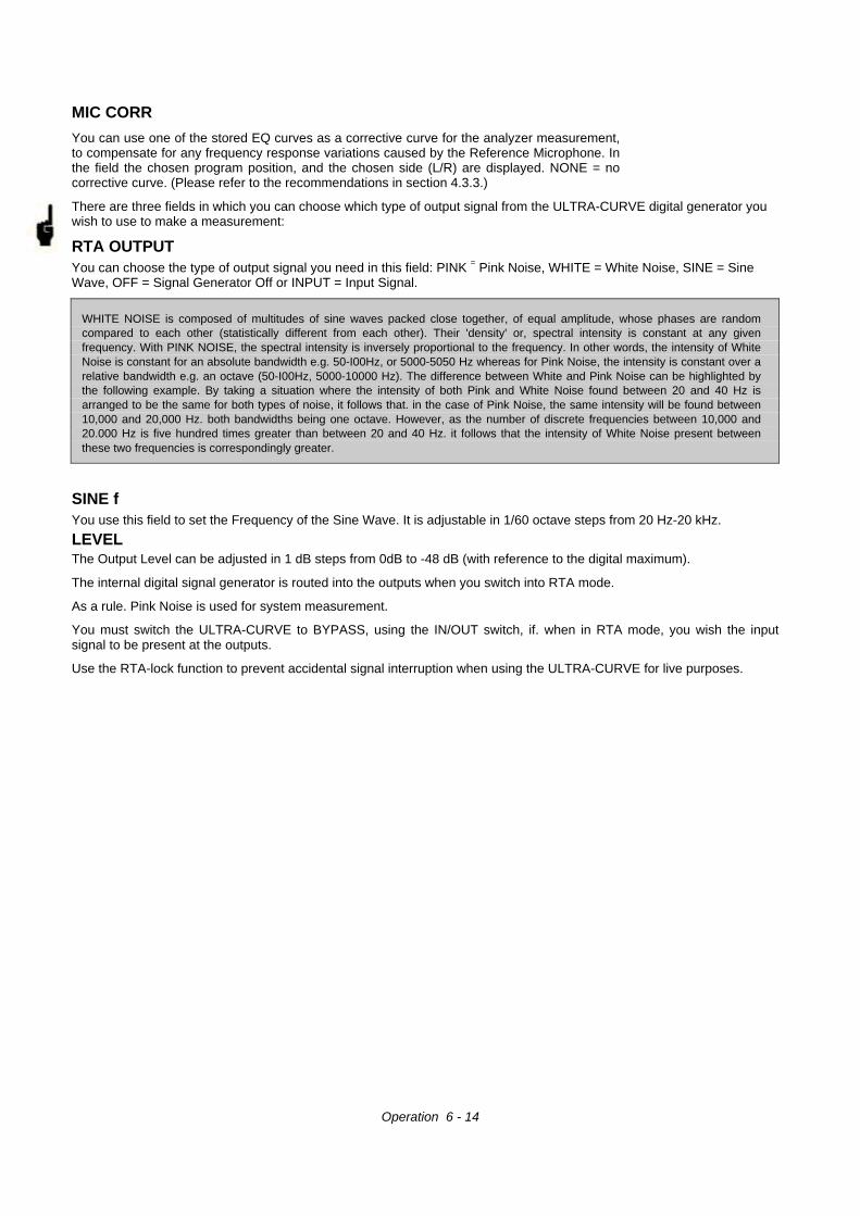
MIC CORR
You can use one of the stored EQ curves as a corrective curve for the analyzer measurement,to compensate for any frequency response variations caused by the Reference Microphone. Inthe field the chosen program position, and the chosen side (L/R) are displayed. NONE = nocorrective curve. (Please refer to the recommendations in section 4.3.3.)
There are three fields in which you can choose which type of output signal from the ULTRA-CURVE digital generator youwish to use to make a measurement:
RTA OUTPUTYou can choose the type of output signal you need in this field: PINK = Pink Noise, WHITE = White Noise, SINE = SineWave, OFF = Signal Generator Off or INPUT = Input Signal.
WHITE NOISE is composed of multitudes of sine waves packed close together, of equal amplitude, whose phases are randomcompared to each other (statistically different from each other). Their 'density' or, spectral intensity is constant at any givenfrequency. With PINK NOISE, the spectral intensity is inversely proportional to the frequency. In other words, the intensity of WhiteNoise is constant for an absolute bandwidth e.g. 50-I00Hz, or 5000-5050 Hz whereas for Pink Noise, the intensity is constant over arelative bandwidth e.g. an octave (50-I00Hz, 5000-10000 Hz). The difference between White and Pink Noise can be highlighted bythe following example. By taking a situation where the intensity of both Pink and White Noise found between 20 and 40 Hz isarranged to be the same for both types of noise, it follows that. in the case of Pink Noise, the same intensity will be found between10,000 and 20,000 Hz. both bandwidths being one octave. However, as the number of discrete frequencies between 10,000 and20.000 Hz is five hundred times greater than between 20 and 40 Hz. it follows that the intensity of White Noise present betweenthese two frequencies is correspondingly greater.
SINE fYou use this field to set the Frequency of the Sine Wave. It is adjustable in 1/60 octave steps from 20 Hz-20 kHz.
LEVELThe Output Level can be adjusted in 1 dB steps from 0dB to -48 dB (with reference to the digital maximum).
The internal digital signal generator is routed into the outputs when you switch into RTA mode.
As a rule. Pink Noise is used for system measurement.
You must switch the ULTRA-CURVE to BYPASS, using the IN/OUT switch, if. when in RTA mode, you wish the inputsignal to be present at the outputs.
Use the RTA-lock function to prevent accidental signal interruption when using the ULTRA-CURVE for live purposes.
Operation 6 - 14
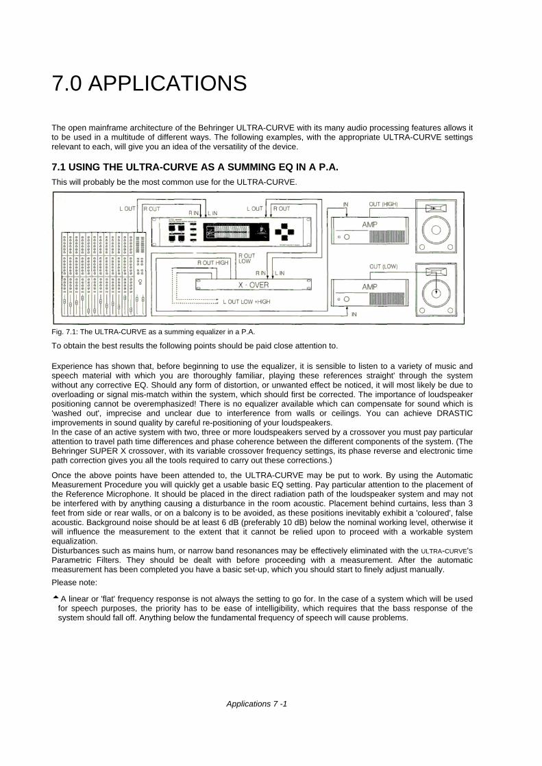
7.0 APPLICATIONS
The open mainframe architecture of the Behringer ULTRA-CURVE with its many audio processing features allows itto be used in a multitude of different ways. The following examples, with the appropriate ULTRA-CURVE settingsrelevant to each, will give you an idea of the versatility of the device.
7.1 USING THE ULTRA-CURVE AS A SUMMING EQ IN A P.A.This will probably be the most common use for the ULTRA-CURVE.
Fig. 7.1: The ULTRA-CURVE as a summing equalizer in a P.A.
To obtain the best results the following points should be paid close attention to.
Experience has shown that, before beginning to use the equalizer, it is sensible to listen to a variety of music andspeech material with which you are thoroughly familiar, playing these references straight' through the systemwithout any corrective EQ. Should any form of distortion, or unwanted effect be noticed, it will most likely be due tooverloading or signal mis-match within the system, which should first be corrected. The importance of loudspeakerpositioning cannot be overemphasized! There is no equalizer available which can compensate for sound which is'washed out', imprecise and unclear due to interference from walls or ceilings. You can achieve DRASTICimprovements in sound quality by careful re-positioning of your loudspeakers.In the case of an active system with two, three or more loudspeakers served by a crossover you must pay particularattention to travel path time differences and phase coherence between the different components of the system. (TheBehringer SUPER X crossover, with its variable crossover frequency settings, its phase reverse and electronic timepath correction gives you all the tools required to carry out these corrections.)
Once the above points have been attended to, the ULTRA-CURVE may be put to work. By using the AutomaticMeasurement Procedure you will quickly get a usable basic EQ setting. Pay particular attention to the placement ofthe Reference Microphone. It should be placed in the direct radiation path of the loudspeaker system and may notbe interfered with by anything causing a disturbance in the room acoustic. Placement behind curtains, less than 3feet from side or rear walls, or on a balcony is to be avoided, as these positions inevitably exhibit a 'coloured', falseacoustic. Background noise should be at least 6 dB (preferably 10 dB) below the nominal working level, otherwise itwill influence the measurement to the extent that it cannot be relied upon to proceed with a workable systemequalization.Disturbances such as mains hum, or narrow band resonances may be effectively eliminated with the ULTRA-CURVE'SParametric Filters. They should be dealt with before proceeding with a measurement. After the automaticmeasurement has been completed you have a basic set-up, which you should start to finely adjust manually.
Please note:
5A linear or 'flat' frequency response is not always the setting to go for. In the case of a system which will be usedfor speech purposes, the priority has to be ease of intelligibility, which requires that the bass response of thesystem should fall off. Anything below the fundamental frequency of speech will cause problems.
Applications 7 -1
5 Very low and high frequencies will usually be amplified (carried over) to a much lesser extent. There is nosense in driving a loudspeaker cabinet designed only for speech/vocal use hard at frequencies below 50Hz. Apart from the increase in power required, this can also result in very expensive loudspeaker repairs.Always be aware of and work within the physical limitations of your system.
5 If time allows make several measurements with the Reference Microphone in different positions. The figurebelow shows some suitable positions for taking measurements.
Fig. 7.2: Recommended positions for measurements with the Reference Microphone
Positions 1 and 2 are about three feet directly in front of the loudspeaker system, positioned halfwaybetween the middle and high frequency components. These measurements can be used as a control ofthe basic system functions.
Position 3 is about seven feet in front of the stage centre. Measurements taken here should show anidentical response above 250 Hz as obtained from positions 1 and 2. Due to the summing of bothloudspeaker systems, the level below 250 Hz should be 3 dB higher.
Position 4 is some way back from position 3, directly in front of the FOH mixing position. (FOH meansfront of house). The measurements here should be the same as at position 3, with a lower level.
Positions 5 and 6 are on the axes of the two loudspeaker systems, three feet away from the rear wall.These measurements are used to detect any problems caused by standing waves or reflections.
5 Make sure to save the resulting frequency response curves for comparison purposes. Any majordifferences between the various measurements should be interpreted as warnings of phase problemswithin the system or acoustical problems in the room. If you are not able to deal with the source of theseproblems (by moving speakers, or changing the venue), then you can only attempt to find a workablecompromise with the equalizer. For this purpose, the various stored measurements will be of greatassistance.
5 After reaching the desired frequency settings on the equalizer, walk around the room and pay particularattention to any change in the sound as you move around. Don't forget to periodically listen to yourreference music and spoken material to help 'refresh' your ears and particularly to get a more objectivefeeling for the characteristics and sound of your system and the room.
You must be prepared to invest plenty of time and patience to obtain an effective equalizer setting!
Applications 7 - 2
Beware of using extreme settings to achieve the sound you are looking for. They are inevitably a warning thatsomething is wrong with your system.
An equalizer cannot compensate for a bad sound system, however it is a flexible and very useful tool for finetuning sound. With practice you will see that subtle changes brought about with the equalizer can greatlyenhance the ability of your system to deliver a clear, well defined sound, measurably improving its overallquality.
7.2 USING THE ULTRA-CURVE FOR MONITOR EQ PURPOSES
In using the ULTRA-CURVE in a monitor signal path, you should apply the ground rules discussed in the lastsection for RA. use. In addition, the ULTRA-CURVE has a number of features designed specifically to assist inmonitor equalizing.
5 The FEEDBACK DESTROYER enables you, during soundcheck, to locate and control any frequenciescausing feedback problems. (In this case, having detected a problem frequency, you match the filter to thefrequency by switching on "-" in the FB-D menu).
5 In the case of microphones which are constantly moving (typically hand held vocal microphones) thefeedback conditions are continuously changing. Use the FEEDBACK DESTROYER filter in searching mode("S") to compensate for this.
The FEEDBACK DESTROYER is only suitable for use with signals with a large, changing dynamic (speech,singing, percussion). Long, static signals such as synthesizer or flute, whose sound characteristics havesimilarities to sine waves, cannot be distinguished from feedback, resulting in their signal being constantlydampened.If, in "SEARCHING" mode, all the available filters are being used, in the case of a new frequency being found,the 'oldest' filter in use will be released from its set frequency and made available for the new one.The FEEDBACK DESTROYER cannot work miracles! It is capable of raising the feedback threshold by only afew dBs. Seeing the FEEDBACK DESTROYER switching on should be interpreted as a warning signal. Lowerthe overall volume on stage.
In principle the stage volume really should be kept as low as possible, because:1.) It is better for everybody's hearing!2.) It results in fewer feedback problems.3.) It is easier to get a good FOH sound.The monitor level tends to rise during the course of a concert. Therefore you should use any pause in theconcert to reduce all monitor levels by about 3 dB. This reduction will, if at all, be barely noticeable to themusicians - their hearing will recover sensitivity during a pause - the end result is that you recover valuableheadroom.
5 If you are repeatedly using the same monitor loudspeakers, you can save the EQ settings which you have setfor these speakers (store them under names such as WEDGE 15" or DRUMFILL).
5 Extremely low frequencies should be filtered out to avoid a 'muddy' stage sound.
TIP: Set the shelving tool to give you a high pass filter. (Set the shelving slope in EQ SETUP to 30 dB.)By using the horizontal cursor keys you can easily change the cut-off frequency for the high pass filter, to enableyou to rapidly tailor the monitor sound to suit the program being reproduced.
If you have a large system with a separate monitor mix and more than 4 independent monitor sub-mixes, werecommend the use of one ULTRA-CURVE solely as an analyzer. The figure on top of the following page givesan example for the use of several ULTRA-CURVEs in a multiway monitor application.
The AFL output from the monitor mixing desk is normally used to feed a loudspeaker at the mixing position. Youcan feed this output through the analyzer line input. The ULTRA-CURVE will then switch its display frommicrophone to line, and the output signal from the AFL will be present at the line input to be analyzed.
Applications 7 - 3
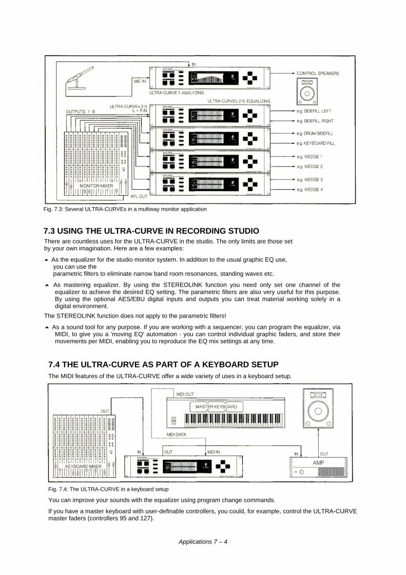
Fig. 7.3: Several ULTRA-CURVEs in a multiway monitor application
7.3 USING THE ULTRA-CURVE IN RECORDING STUDIOThere are countless uses for the ULTRA-CURVE in the studio. The only limits are those setby your own imagination. Here are a few examples:
5 As the equalizer for the studio monitor system. In addition to the usual graphic EQ use,you can use theparametric filters to eliminate narrow band room resonances, standing waves etc.
5 As mastering equalizer. By using the STEREOLINK function you need only set one channel of theequalizer to achieve the desired EQ setting. The parametric filters are also very useful for this purpose.By using the optional AES/EBU digital inputs and outputs you can treat material working solely in adigital environment.
The STEREOLINK function does not apply to the parametric filters!
5 As a sound tool for any purpose. If you are working with a sequencer, you can program the equalizer, viaMIDI, to give you a 'moving EQ' automation - you can control individual graphic faders, and store theirmovements per MIDI, enabling you to reproduce the EQ mix settings at any time.
7.4 THE ULTRA-CURVE AS PART OF A KEYBOARD SETUPThe MIDI features of the ULTRA-CURVE offer a wide variety of uses in a keyboard setup.
Fig. 7.4: The ULTRA-CURVE in a keyboard setup
You can improve your sounds with the equalizer using program change commands.
If you have a master keyboard with user-definable controllers, you could, for example, control the ULTRA-CURVEmaster faders (controllers 95 and 127).
Applications 7 – 4
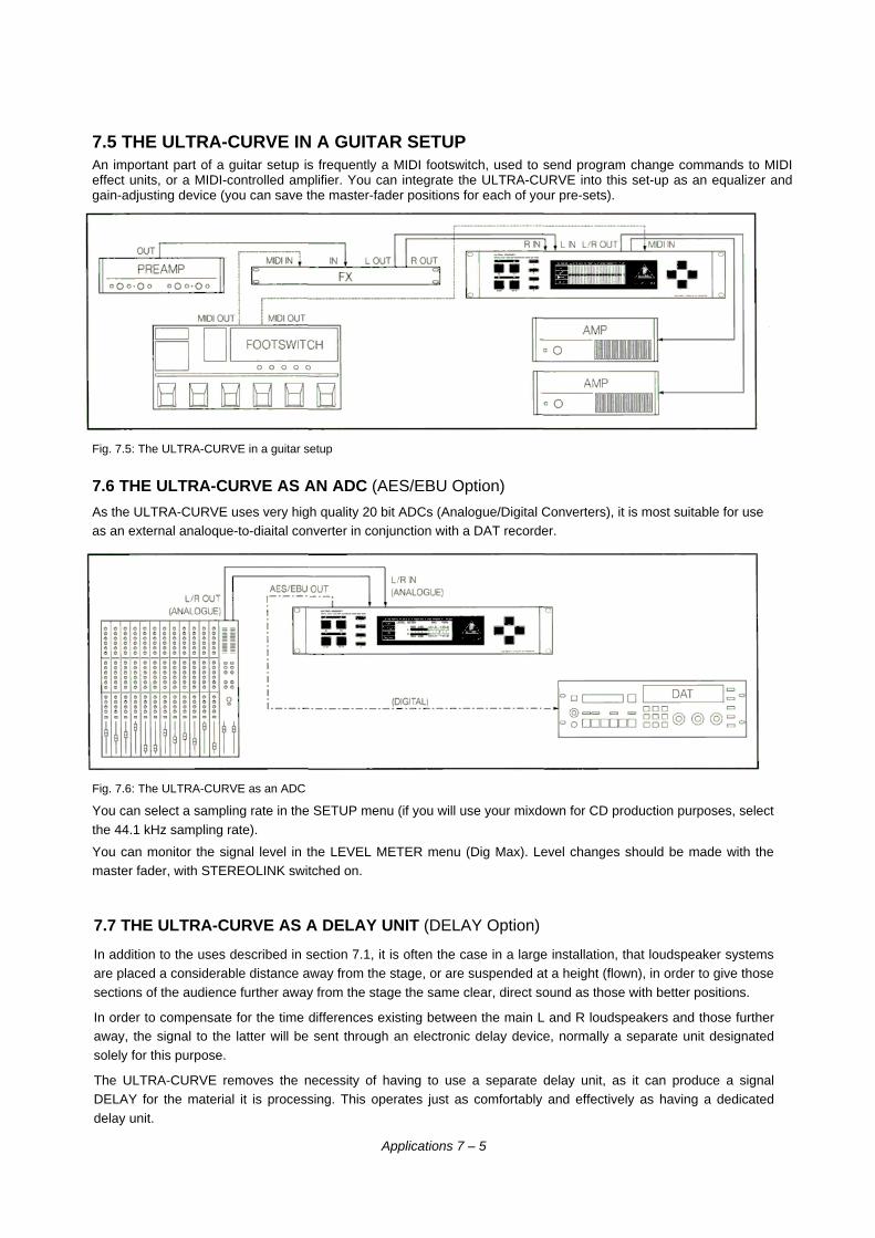
7.5 THE ULTRA-CURVE IN A GUITAR SETUPAn important part of a guitar setup is frequently a MIDI footswitch, used to send program change commands to MIDIeffect units, or a MIDI-controlled amplifier. You can integrate the ULTRA-CURVE into this set-up as an equalizer andgain-adjusting device (you can save the master-fader positions for each of your pre-sets).
Fig. 7.5: The ULTRA-CURVE in a guitar setup
7.6 THE ULTRA-CURVE AS AN ADC (AES/EBU Option)
As the ULTRA-CURVE uses very high quality 20 bit ADCs (Analogue/Digital Converters), it is most suitable for useas an external analoque-to-diaital converter in conjunction with a DAT recorder.
Fig. 7.6: The ULTRA-CURVE as an ADC
You can select a sampling rate in the SETUP menu (if you will use your mixdown for CD production purposes, selectthe 44.1 kHz sampling rate).
You can monitor the signal level in the LEVEL METER menu (Dig Max). Level changes should be made with themaster fader, with STEREOLINK switched on.
7.7 THE ULTRA-CURVE AS A DELAY UNIT (DELAY Option)
In addition to the uses described in section 7.1, it is often the case in a large installation, that loudspeaker systemsare placed a considerable distance away from the stage, or are suspended at a height (flown), in order to give thosesections of the audience further away from the stage the same clear, direct sound as those with better positions.
In order to compensate for the time differences existing between the main L and R loudspeakers and those furtheraway, the signal to the latter will be sent through an electronic delay device, normally a separate unit designatedsolely for this purpose.
The ULTRA-CURVE removes the necessity of having to use a separate delay unit, as it can produce a signalDELAY for the material it is processing. This operates just as comfortably and effectively as having a dedicateddelay unit.
Applications 7 – 5
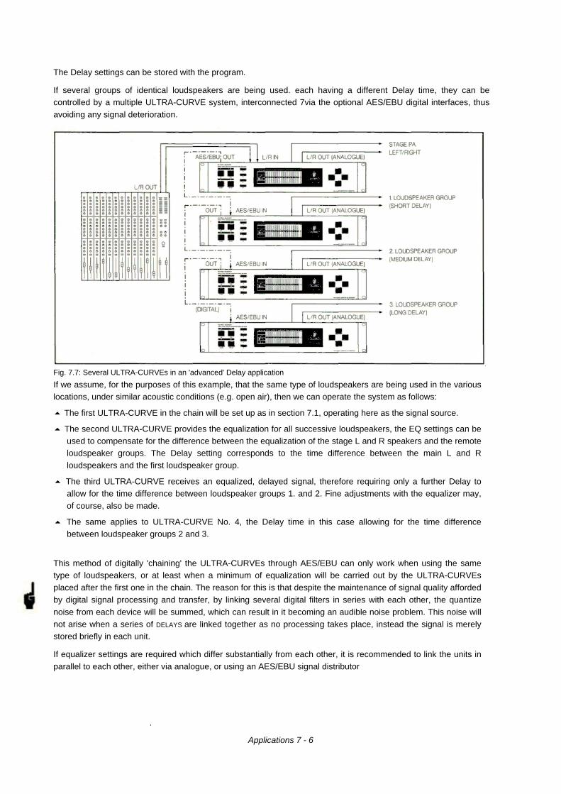
The Delay settings can be stored with the program.
If several groups of identical loudspeakers are being used. each having a different Delay time, they can becontrolled by a multiple ULTRA-CURVE system, interconnected 7via the optional AES/EBU digital interfaces, thusavoiding any signal deterioration.
Fig. 7.7: Several ULTRA-CURVEs in an 'advanced' Delay application
If we assume, for the purposes of this example, that the same type of loudspeakers are being used in the variouslocations, under similar acoustic conditions (e.g. open air), then we can operate the system as follows:
5 The first ULTRA-CURVE in the chain will be set up as in section 7.1, operating here as the signal source.
5 The second ULTRA-CURVE provides the equalization for all successive loudspeakers, the EQ settings can beused to compensate for the difference between the equalization of the stage L and R speakers and the remoteloudspeaker groups. The Delay setting corresponds to the time difference between the main L and Rloudspeakers and the first loudspeaker group.
5 The third ULTRA-CURVE receives an equalized, delayed signal, therefore requiring only a further Delay toallow for the time difference between loudspeaker groups 1. and 2. Fine adjustments with the equalizer may,of course, also be made.
5 The same applies to ULTRA-CURVE No. 4, the Delay time in this case allowing for the time differencebetween loudspeaker groups 2 and 3.
This method of digitally 'chaining' the ULTRA-CURVEs through AES/EBU can only work when using the sametype of loudspeakers, or at least when a minimum of equalization will be carried out by the ULTRA-CURVEsplaced after the first one in the chain. The reason for this is that despite the maintenance of signal quality affordedby digital signal processing and transfer, by linking several digital filters in series with each other, the quantizenoise from each device will be summed, which can result in it becoming an audible noise problem. This noise willnot arise when a series of DELAYS are linked together as no processing takes place, instead the signal is merelystored briefly in each unit.
If equalizer settings are required which differ substantially from each other, it is recommended to link the units inparallel to each other, either via analogue, or using an AES/EBU signal distributor
.
Applications 7 - 6
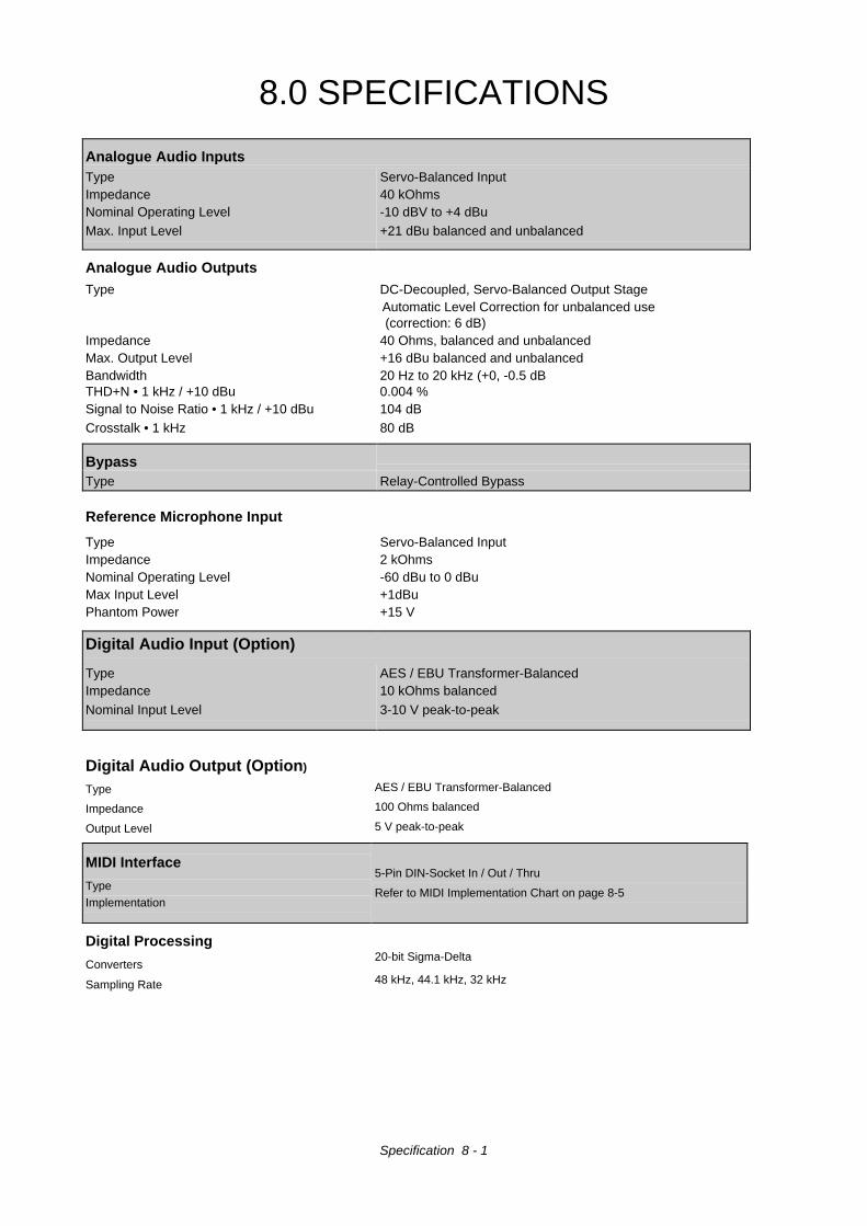
8.0 SPECIFICATIONS
Analogue Audio InputsType Servo-Balanced InputImpedance 40 kOhmsNominal Operating Level -10 dBV to +4 dBuMax. Input Level +21 dBu balanced and unbalanced
Analogue Audio OutputsType DC-Decoupled, Servo-Balanced Output Stage
Automatic Level Correction for unbalanced use(correction: 6 dB)
Impedance 40 Ohms, balanced and unbalancedMax. Output Level +16 dBu balanced and unbalancedBandwidth 20 Hz to 20 kHz (+0, -0.5 dBTHD+N • 1 kHz / +10 dBu 0.004 %Signal to Noise Ratio • 1 kHz / +10 dBu 104 dBCrosstalk • 1 kHz 80 dB
BypassType Relay-Controlled Bypass
Reference Microphone Input
Type Servo-Balanced InputImpedance 2 kOhmsNominal Operating Level -60 dBu to 0 dBuMax Input Level +1dBuPhantom Power +15 V
Digital Audio Input (Option)
Type AES / EBU Transformer-BalancedImpedance 10 kOhms balanced
Nominal Input Level 3-10 V peak-to-peak
Digital Audio Output (Option)
Type
Impedance
Output Level
AES / EBU Transformer-Balanced
100 Ohms balanced
5 V peak-to-peak
MIDI Interface
TypeImplementation
5-Pin DIN-Socket In / Out / Thru
Refer to MIDI Implementation Chart on page 8-5
Digital Processing
Converters
Sampling Rate
20-bit Sigma-Delta
48 kHz, 44.1 kHz, 32 kHz
Specification 8 - 1
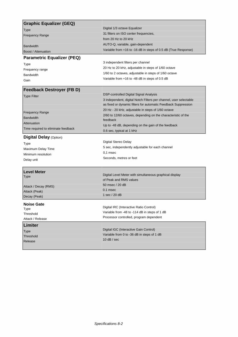
Graphic Equalizer (GEQ)Type
Frequency Range
Bandwidth
Boost / Attenuation
Digital 1/3 octave Equalizer
31 filters on ISO center frequencies,
from 20 Hz to 20 kHz
AUTO-Q, variable, gain-dependent
Variable from +16 to -16 dB in steps of 0.5 dB (True Response)
Parametric Equalizer (PEQ)Type
Frequency range
Bandwidth
Gain
3 independent filters per channel
20 Hz to 20 kHz, adjustable in steps of 1/60 octave
1/60 to 2 octaves, adjustable in steps of 1/60 octave
Variable from +16 to -48 dB in steps of 0.5 dB
Feedback Destroyer (FB D)Type Filter
Frequency Range
Bandwidth
Attenuation
Time required to eliminate feedback
DSP-controlled Digital Signal Analysis
3 independent, digital Notch Filters per channel, user selectableas fixed or dynamic filters for automatic Feedback Suppression
20 Hz - 20 kHz, adjustable in steps of 1/60 octave
2/60 to 12/60 octaves, depending on the characteristic of thefeedback
Up to -48 dB, depending on the gain of the feedback
0.6 sec, typical at 1 kHz
Digital Delay (Option)
Type
Maximum Delay Time
Minimum resolution
Delay unit
Digital Stereo Delay
5 sec, independently adjustable for each channel
0,1 msec
Seconds, metres or feet
Level MeterType
Attack / Decay (RMS)
Attack (Peak)
Decay (Peak)
Digital Level Meter with simultaneous graphical display
of Peak and RMS values
50 msec / 20 dB
0.1 msec
1 sec / 20 dB
Noise GateType
Threshold
Attack / Release
Digital IRC (Interactive Ratio Control)
Variable from -48 to -114 dB in steps of 1 dB
Processor controlled, program dependent
LimiterType
Threshold
Release
Digital IGC (Interactive Gain Control)
Variable from 0 to -36 dB in steps of 1 dB
10 dB / sec
Specifications 8-2
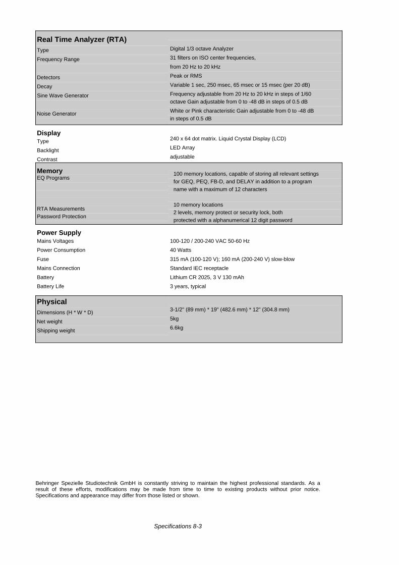
Real Time Analyzer (RTA)Type
Frequency Range
Detectors
Decay
Sine Wave Generator
Noise Generator
Digital 1/3 octave Analyzer
31 filters on ISO center frequencies,
from 20 Hz to 20 kHz
Peak or RMS
Variable 1 sec, 250 msec, 65 msec or 15 msec (per 20 dB)
Frequency adjustable from 20 Hz to 20 kHz in steps of 1/60octave Gain adjustable from 0 to -48 dB in steps of 0.5 dB
White or Pink characteristic Gain adjustable from 0 to -48 dBin steps of 0.5 dB
DisplayType
Backlight
Contrast
240 x 64 dot matrix. Liquid Crystal Display (LCD)
LED Array
adjustable
MemoryEQ Programs
RTA MeasurementsPassword Protection
100 memory locations, capable of storing all relevant settingsfor GEQ, PEQ, FB-D, and DELAY in addition to a programname with a maximum of 12 characters
10 memory locations2 levels, memory protect or security lock, bothprotected with a alphanumerical 12 digit password
Power SupplyMains Voltages
Power Consumption
Fuse
Mains Connection
Battery
Battery Life
100-120 / 200-240 VAC 50-60 Hz
40 Watts
315 mA (100-120 V); 160 mA (200-240 V) slow-blow
Standard IEC receptacle
Lithium CR 2025, 3 V 130 mAh
3 years, typical
PhysicalDimensions (H * W * D)
Net weight
Shipping weight
3-1/2" (89 mm) * 19" (482.6 mm) * 12" (304.8 mm)
5kg
6.6kg
Behringer Spezielle Studiotechnik GmbH is constantly striving to maintain the highest professional standards. As aresult of these efforts, modifications may be made from time to time to existing products without prior notice.Specifications and appearance may differ from those listed or shown.
Specifications 8-3
8.1 OPTIONS AND DEVELOPMENTS
8.1.1 Options
The following options will be available for the ULTRA-CURVE:
DELAY 8000Contains the Delay functions. It consists of RAM memory chips, as well as operating software (EPROM).
AES 8000The digital AES/EBU Input and Output. Consists of an additional circuit board with the driver software forthe AES/EBU connections, the XLR connectors and balancing transformers, plus an update for theoperating software.
Both options may be installed simultaneously.You have the choice of ordering the options with the purchase of your ULTRA-CURVE, or adding them ata later stage. To do this, send your ULTRA-CURVE postage paid to the address mentioned in chapter 9.
Return your ULTRA-CURVE to us for the installation, otherwise you will invalidate your warranty.
8.1.2 Operating Software
The ULTRA-CURVE operating software is under continuous development to improve its performance andcontrol, and to keep pace with your expectations and requirements. Therefore you are asked to contact uswith your needs, suggestions and ideas. We will make every effort to put your ideas into use in successivesoftware updates. In order to receive a new software update, you must send your ULTRA-CURVE to theabove address. Information about new software versions will be available through music magazines, fromyour dealer or directly from Behringer Spezielle Studiotechnik GmbH Phone +49 / 2154 / 9206-0
The current software version will always be displayed shortly after switching the ULTRA-CURVE on (belowright edge of the display).You will automatically receive the latest software when you order the "DELAY 8000" or "AES 8000"options.
8.1.3 Changing the Memory Protect Battery
The battery which maintains the program memory when power is switched off has a life of several years,depending on the frequency and duration of use. When the battery starts to run out you will see themessage:
WARNING: BATTERY LOW
You should send the unit back to us as quickly as possible. We are able to replace the battery withoutlosing the programs stored in the memory
If you fail to heed the warning to replace the battery the display will show the message:
BATTERY EMPTY: MEMORY CLEARED.If this happens, you will have lost all your programs. Furthermore, new programs will also be lost once theULTRA-CURVE is switched off.
8.1.4 Under Development
5 A software program to run on a PC designed to control one or more ULTRA-CURVEs via MIDI, withextra functions and improved ease of use. The software will require an IBM compatible PC with a MIDIinterface, together with a new operating software with extended MIDI functions for the ULTRA-CURVE(s).
5 A development of the ULTRA-CURVE system software to allow master-slave control via MIDI.
Specifications 8-4
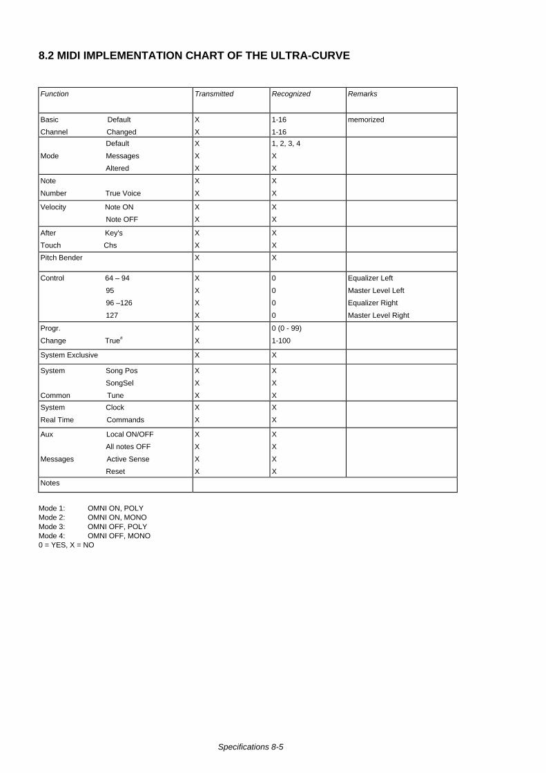
8.2 MIDI IMPLEMENTATION CHART OF THE ULTRA-CURVE
Function Transmitted Recognized Remarks
Basic Default
Channel Changed
X
X
1-16
1-16
memorized
Default
Mode Messages
Altered
X
X
X
1, 2, 3, 4
X
X
Note
Number True Voice
X
X
X
X
Velocity Note ON
Note OFF
X
X
X
X
After Key's
Touch Chs
X
X
X
X
Pitch Bender X X
Control 64 – 94
95
96 –126
127
X
X
X
X
0
0
0
0
Equalizer Left
Master Level Left
Equalizer Right
Master Level Right
Progr.
Change True#
X
X
0 (0 - 99)
1-100
System Exclusive X X
System Song Pos
SongSel
Common Tune
X
X
X
X
X
X
System Clock
Real Time Commands
X
X
X
X
Aux Local ON/OFF
All notes OFF
Messages Active Sense
Reset
X
X
X
X
X
X
X
X
Notes
Mode 1: OMNI ON, POLYMode 2: OMNI ON, MONOMode 3: OMNI OFF, POLYMode 4: OMNI OFF, MONO0 = YES, X = NO
Specifications 8-5
9.0 WARRANTY
§ 1 WARRANTY REGISTRATIONWarranty Registration must be completed and returned to Behringer GmbH within 8 days from the date of purchase.
§ 2 WARRANTYBehringer GmbH warrants the materials, workmanship and proper operation of this Behringer product for a period of 12 monthsfrom the original date of purchase. If any defects are found in the materials or workmanship, or if the product fails to functionproperly within the specified warranty period, Behringer GmbH will repair or replace the product, at its discretion.
§ 3 RETURN AUTHORIZATION NUMBER (RA)
1. To obtain factory service call Behringer GmbH for a Return Authorization Number. RA numbers arenecessary for proper tracking of your product. Call:
Tel. (0) 21 54 / 92 06 - 0 (10 am to 5 pm weekdays (MET))
2. The product must be returned in its original shipping carton, freight prepaid to:
BEHRINGER Spezielle Studiotechnik GmbH
Hanns-Martin-Schleyer-Str. 36-38,
FRG-47877 Willich/Munchheide II
Federal Republic of Germany
§ 4 WARRANTY AUTHORITYBehringer GmbH reserves the right to inspect any products which may be the subject of any warranty claim before repair orreplacement is carried out.
Behringer GmbH may, at its discretion, require proof of the original date of purchase (dated copy of original retail dealer's invoice).Final determination of warranty coverage lies solely with Behringer GmbH. Any Behringer product deemed eligible for repair orreplacement under the terms of this warranty will be repaired or replaced within 30 days of receipt of the product at Behringer'sfactory. Products which do not meet the terms of this warranty will be repaired and returned C.O.D. with an invoice for labour,materials, return freight and insurance. Products repaired under warranty will be returned freight prepaid by Behringer GmbH, toany location within the boundaries of the Federal Republic of Germany. Outside of Germany, products will be returned freightcollect.
§ 5 WARRANTY TRANSFERABILITYThis warranty is extended to the original purchaser, but it is not transferable to anyone who may subsequently purchase thisproduct.
§ 6 LIMITATION OF LIABILITYBehringer products are designed and manufactured for use in professional and studio audio systems and are not intended for anyother use. With respect to products purchased by consumers for personal, family or household use, Behringer GmbH expresslydisclaims all implied warranties, including but not limited to warranties of merchantability and fitness for a particular purpose.
The foregoing warranties are in lieu of all other warranties, whether oral. written, expressed, implied or statutory. BehringerGmbH's warranty obligation and Buyer's remedies hereunder are solely and exclusively as stated herein.
The total liability of Behringer GmbH on any claim, whether in contract, tort (including negligence) or otherwise arising out of,connected with, or resulting from the manufacturer, sale delivery, resale, repair, replacement or use of any product will not exceedthe price allocable to the product or part thereof which gives rise to the claim. In no event will Behringer GmbH be liable for anyincidental or consequential damages including but not limited to damage for loss of revenue, cost of capital, claims of customersfor service interruptions or failure to supply and costs and expenses incurred in connection with labour, overhead, transportation,installation or removal of products or substitute facilities or supply sources.
Warranty 9 –1