Embed Size (px)
Citation preview
User Manual
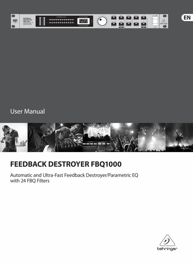
FEEDBACK DESTROYER FBQ1000Automatic and Ultra-Fast Feedback Destroyer/Parametric EQ with 24 FBQ Filters
2 FEEDBACK DESTROYER FBQ1000 User Manual
Thank youThank you very much for expressing your confidence in BEHRINGER products by purchasing the FEEDBACK DESTROYER FBQ1000. With the FEEDBACK DESTROYER you have acquired a highly useful device for the control of sound reinforcement systems, which will enable you to focus your attention on what is essential: your music. The fully featured FBQ1000 not only suppresses feedback but also incorporates a wealth of additional functions in one single unit. Its 24 separate filters can be edited in all parameters, and automatically detect and suppress feedback frequencies. With its pro-level internal processing circuitry, the unit can also be used as a high-end equalizer for stage and studio applications. The MIDI interface allows for integrating the FBQ1000 into any MIDI system, and the open system architecture enables you to update the system software whenever you want. In short: the FBQ1000 will be your reliable “workhorse” over many years to come.
Table of ContentsThank you ....................................................................... 2
Important Safety Instructions ...................................... 3
Legal Disclaimer ............................................................. 3
Limited warranty ............................................................ 3
1. Introduction ............................................................... 4
2. Applications ............................................................... 5
3. A Few Quick Steps to Eliminate Feedback .............. 6
4. Control Elements ....................................................... 6
5. FBQ1000 Architecture: Presets, Filters, Operating Modes ................................ 7
6. Operating Modes of the FBQ1000 ............................ 8
7. Working with Presets ................................................ 8
8. Problems Do Have A Cause ... ................................. 10
9. MIDI Control ............................................................. 10
10. Installation ............................................................. 11
11. Appendix ................................................................ 12
12. Specifications ......................................................... 15
3 FEEDBACK DESTROYER FBQ1000 User Manual
Important Safety Instructions
LEGAL DISCLAIMER
LIMITED WARRANTY
Terminals marked with this symbol carry electrical current of suffi cient magnitude to constitute risk of electric shock.
Use only high-quality professional speaker cables with ¼" TS or twist-locking plugs pre-installed. All other installation or modifi cation should be performed only by qualifi ed personnel.
This symbol, wherever it appears, alerts you to the presence of uninsulated dangerous voltage inside the
enclosure - voltage that may be suffi cient to constitute a risk of shock.
This symbol, wherever it appears, alerts you to important operating and maintenance instructions in the
accompanying literature. Please read the manual.
CautionTo reduce the risk of electric shock, do not remove the top cover (or the rear section).
No user serviceable parts inside. Refer servicing to qualifi ed personnel.
CautionTo reduce the risk of fi re or electric shock, do not expose this appliance to rain and
moisture. The apparatus shall not be exposed to dripping or splashing liquids and no objects fi lled with liquids, such as vases, shall be placed on the apparatus.
CautionThese service instructions are for use by qualifi ed service personnel only.
To reduce the risk of electric shock do not perform any servicing other than that contained in the operation instructions. Repairs have to be performed by qualifi ed service personnel.
1. Read these instructions.
2. Keep these instructions.
3. Heed all warnings.
4. Follow all instructions.
5. Do not use this apparatus near water.
6. Clean only with dry cloth.
7. Do not block any ventilation openings. Install in accordance with the manufacturer’s instructions.
8. Do not install near any heat sources such as radiators, heat registers, stoves, or other apparatus (including amplifi ers) that produce heat.
9. Do not defeat the safety purpose of the polarized or grounding-type plug. A polarized plug has two blades with one wider than the other. A grounding-type plug has two blades and a third grounding prong. The wide blade or the third prong are provided for your safety. If the provided plug does not fi t into your outlet, consult an electrician for replacement of the obsolete outlet.
10. Protect the power cord from being walked on or pinched particularly at plugs, convenience receptacles, and the point where they exit from the apparatus.
11. Use only attachments/accessories specifi ed by the manufacturer.
12. Use only with the cart, stand, tripod, bracket, or table specifi ed by the manufacturer, or sold with the apparatus. When a cart is used, use caution when moving the cart/apparatus combination to avoid
injury from tip-over.
13. Unplug this apparatus during lightning storms or when unused for long periods of time.
14. Refer all servicing to qualifi ed service personnel. Servicing is required when the apparatus has been damaged in any way, such as power supply cord or plug is damaged, liquid has been spilled or objects have fallen into the apparatus, the apparatus has been exposed to rain or moisture, does not operate normally, or has been dropped.
15. The apparatus shall be connected to a MAINS socket outlet with a protective earthing connection.
16. Where the MAINS plug or an appliance coupler is used as the disconnect device, the disconnect device shall remain readily operable.
TECHNICAL SPECIFICATIONS AND APPEARANCES ARE SUBJECT TO CHANGE WITHOUT NOTICE AND ACCURACY IS NOT GUARANTEED. BEHRINGER, KLARK TEKNIK, MIDAS, BUGERA, AND TURBOSOUND ARE PART OF THE MUSIC GROUP (MUSIC-GROUP.COM). ALL TRADEMARKS ARE THE PROPERTY OF THEIR RESPECTIVE OWNERS. MUSIC GROUP ACCEPTS NO LIABILITY FOR ANY LOSS WHICH MAY BE SUFFERED BY ANY PERSON WHO RELIES EITHER WHOLLY OR IN PART UPON ANY DESCRIPTION, PHOTOGRAPH OR STATEMENT CONTAINED HEREIN. COLORS AND SPECIFICATIONS MAY VARY FROM ACTUAL PRODUCT. MUSIC GROUP PRODUCTS ARE SOLD THROUGH AUTHORIZED FULLFILLERS AND RESELLERS ONLY. FULLFILLERS AND RESELLERS ARE NOT AGENTS OF MUSIC GROUP AND HAVE ABSOLUTELY NO AUTHORITY
TO BIND MUSIC GROUP BY ANY EXPRESS OR IMPLIED UNDERTAKING OR REPRESENTATION. THIS MANUAL IS COPYRIGHTED. NO PART OF THIS MANUAL MAY BE REPRODUCED OR TRANSMITTED IN ANY FORM OR BY ANY MEANS, ELECTRONIC OR MECHANICAL, INCLUDING PHOTOCOPYING AND RECORDING OF ANY KIND, FOR ANY PURPOSE, WITHOUT THE EXPRESS WRITTEN PERMISSION OF MUSIC GROUP IP LTD.
ALL RIGHTS RESERVED. © 2013 MUSIC Group IP Ltd.Trident Chambers, Wickhams Cay, P.O. Box 146,Road Town, Tortola, British Virgin Islands
For the applicable warranty terms and conditions and additional information regarding MUSIC Group’s Limited Warranty, please see complete details online at www.music-group.com/warranty.
4 FEEDBACK DESTROYER FBQ1000 User Manual
1. Introduction1.1 The design conceptThe philosophy behind BEHRINGER products guarantees a no-compromise circuit design and employs the best choice of components. A 24-bit DSP is used as the heart of the FEEDBACK DESTROYER, which belongs to the best components available owing to its outstanding specifications and excellent sonic characteristics. What is more, high-quality 24-bit A/D and D/A converters ensure the accurate processing of all signals. Additionally, the FEEDBACK DESTROYER uses high-quality resistors and capacitors with very tight tolerances, high-grade switches, and further selected components.
The FEEDBACK DESTROYER employs SMD technology (Surface Mounted Device). These subminiature components known from aerospace technology allow for an extreme packing density and improve the unit’s reliability even further. Additionally, the FBQ1000 was manufactured in compliance with an ISO9000 certified management system.
1.2 Before you beginYour FEEDBACK DESTROYER was carefully packed in the factory and the packaging was designed to protect the unit from rough handling. Nevertheless, we recommend that you carefully examine the packaging and its contents for any signs of physical damage, which may have occurred in transit.
◊ If the unit is damaged, please do not return it to us, but notify your dealer and the shipping company immediately, otherwise claims for damage or replacement may not be granted. Shipping claims must be made by the consignee.
The BEHRINGER FEEDBACK DESTROYER requires one standard 19" unit of rack space. Please allow at least an additional 4" depth for the connectors on the back panel.
Be sure that there is enough space around the unit for cooling and please do not place the FEEDBACK DESTROYER on high-temperature devices such as power amplifiers, etc. to avoid overheating.
◊ Before you connect your FEEDBACK DESTROYER to the mains, please make sure that your local voltage matches the voltage required by the unit:
The fuse holder on the female mains connector has 3 triangular markings, with two of these triangles opposing each other. The FEEDBACK DESTROYER is set to the operating voltage printed next to these markers and can be set to another voltage by turning the fuse holder by 180°. CAUTION: This instruction does not apply to export models exclusively designed, e.g. for 115-V operation!
Please use the enclosed power cord to connect the unit to the mains. The cord complies with all applicable safety standards.
◊ Please note that all units must be grounded properly. For your own safety, you should never remove any ground connectors from electrical devices or power cords or render them inoperative.
As a standard, the BEHRINGER FEEDBACK DESTROYER is equipped with electronically servo-balanced inputs and outputs. The circuit design features automatic hum and noise reduction for balanced signals and thus allows for trouble-free operation, even at high operating levels. Externally induced mains hum, etc. will be effectively suppressed. The automatic servo-function recognizes the presence of unbalanced connectors and adjusts the nominal level internally to avoid level differences between the input and output signals (6-dB correction).
The MIDI interfaces IN, OUT, and THRU are on standardized DIN connectors. Data are transmitted via potential-free opto couplers.
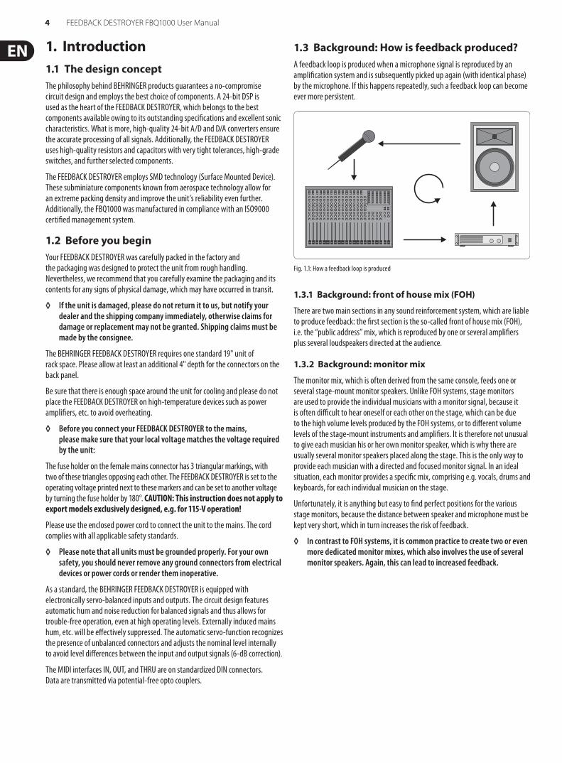
1.3 Background: How is feedback produced?A feedback loop is produced when a microphone signal is reproduced by an amplification system and is subsequently picked up again (with identical phase) by the microphone. If this happens repeatedly, such a feedback loop can become ever more persistent.
Fig. 1.1: How a feedback loop is produced
1.3.1 Background: front of house mix (FOH)
There are two main sections in any sound reinforcement system, which are liable to produce feedback: the first section is the so-called front of house mix (FOH), i.e. the “public address” mix, which is reproduced by one or several amplifiers plus several loudspeakers directed at the audience.
1.3.2 Background: monitor mix
The monitor mix, which is often derived from the same console, feeds one or several stage-mount monitor speakers. Unlike FOH systems, stage monitors are used to provide the individual musicians with a monitor signal, because it is often difficult to hear oneself or each other on the stage, which can be due to the high volume levels produced by the FOH systems, or to different volume levels of the stage-mount instruments and amplifiers. It is therefore not unusual to give each musician his or her own monitor speaker, which is why there are usually several monitor speakers placed along the stage. This is the only way to provide each musician with a directed and focused monitor signal. In an ideal situation, each monitor provides a specific mix, comprising e.g. vocals, drums and keyboards, for each individual musician on the stage.
Unfortunately, it is anything but easy to find perfect positions for the various stage monitors, because the distance between speaker and microphone must be kept very short, which in turn increases the risk of feedback.
◊ In contrast to FOH systems, it is common practice to create two or even more dedicated monitor mixes, which also involves the use of several monitor speakers. Again, this can lead to increased feedback.
5 FEEDBACK DESTROYER FBQ1000 User Manual
2. ApplicationsThe FBQ1000 is used exclusively to eliminate feedback in FOH and monitor mixes.
Before you go on, please note the following two remarks:
◊ The FEEDBACK DESTROYER is not intended to be connected directly to the microphones! If this is unavoidable, then we recommend our proven BEHRINGER SHARK FBQ100 instead, which is equipped with a dedicated microphone preamplifier.
◊ No processing device can undo the mistakes made when placing the microphones! So, when you set up your mics, use them according to their directivity and feedback susceptibility (see chapter 8 “Problems Do Have A Cause ...”).
2.1 Level settingTake care to set levels properly on the FBQ1000, so as to successfully employ the FEEDBACK DESTROYER to remove feedback. Use the LED LEVEL METER (1). Make sure that the top Clip LEDs flicker only rarely, but never light up all the time.
Low levels deteriorate the dynamics of the music signal, which results in a poor, weak and noisy sound. On the other hand, excess levels overdriving the converters in the FEEDBACK DESTROYER should also be avoided. Digital distortion is (unlike its analog counterpart) very unpleasant to hear as it does not occur gradually but abruptly.
2.2 Using the FEEDBACK DESTROYER in the monitor pathYour FBQ1000 is equipped with two channels. In Couple mode (see control elements (8) and (9) ), these two channels are linked. But you can also use them separately, for example, to protect two dedicated monitor paths against feedback.
Monitor mixes are realized either via the pre-fader Aux Sends on an FOH console, or via a (usually stage-mount) monitor mixer. When using an additional monitor mixer on the stage, you need a so-called splitter to route the single microphone signals both to the FOH console and to the monitor mixer. When using the FOH console for the monitor mix, the stage microphones are connected directly to the console (if necessary, via a so-called stage box).
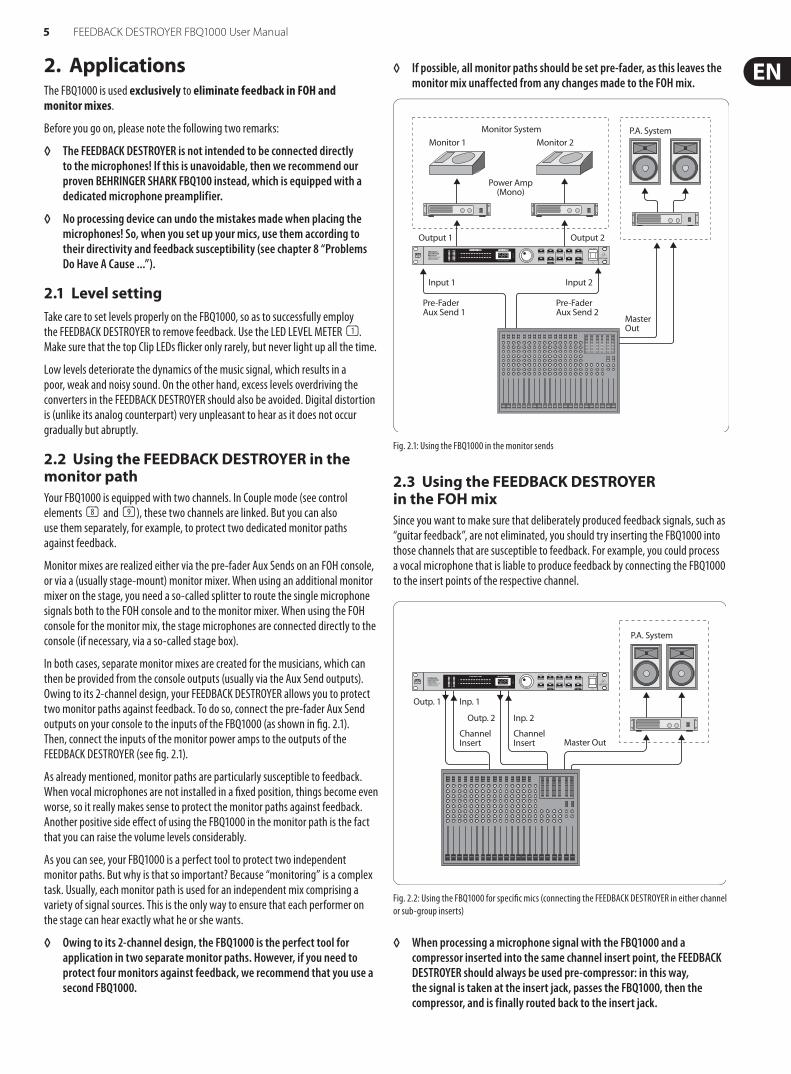
In both cases, separate monitor mixes are created for the musicians, which can then be provided from the console outputs (usually via the Aux Send outputs). Owing to its 2-channel design, your FEEDBACK DESTROYER allows you to protect two monitor paths against feedback. To do so, connect the pre-fader Aux Send outputs on your console to the inputs of the FBQ1000 (as shown in fig. 2.1). Then, connect the inputs of the monitor power amps to the outputs of the FEEDBACK DESTROYER (see fig. 2.1).
As already mentioned, monitor paths are particularly susceptible to feedback. When vocal microphones are not installed in a fixed position, things become even worse, so it really makes sense to protect the monitor paths against feedback. Another positive side effect of using the FBQ1000 in the monitor path is the fact that you can raise the volume levels considerably.
As you can see, your FBQ1000 is a perfect tool to protect two independent monitor paths. But why is that so important? Because “monitoring” is a complex task. Usually, each monitor path is used for an independent mix comprising a variety of signal sources. This is the only way to ensure that each performer on the stage can hear exactly what he or she wants.
◊ Owing to its 2-channel design, the FBQ1000 is the perfect tool for application in two separate monitor paths. However, if you need to protect four monitors against feedback, we recommend that you use a second FBQ1000.
◊ If possible, all monitor paths should be set pre-fader, as this leaves the monitor mix unaffected from any changes made to the FOH mix.
Monitor 1
Output 1
Input 1
Pre-Fader Aux Send 1
Input 2
Pre-Fader Aux Send 2
Master Out
Output 2
Power Amp(Mono)
Monitor 2P.A. SystemMonitor System
Fig. 2.1: Using the FBQ1000 in the monitor sends
2.3 Using the FEEDBACK DESTROYER in the FOH mixSince you want to make sure that deliberately produced feedback signals, such as “guitar feedback”, are not eliminated, you should try inserting the FBQ1000 into those channels that are susceptible to feedback. For example, you could process a vocal microphone that is liable to produce feedback by connecting the FBQ1000 to the insert points of the respective channel.
P.A. System
Outp. 1 Inp. 1
Outp. 2
ChannelInsert
ChannelInsert
Inp. 2
Master Out
Fig. 2.2: Using the FBQ1000 for specific mics (connecting the FEEDBACK DESTROYER in either channel or sub-group inserts)
◊ When processing a microphone signal with the FBQ1000 and a compressor inserted into the same channel insert point, the FEEDBACK DESTROYER should always be used pre-compressor: in this way, the signal is taken at the insert jack, passes the FBQ1000, then the compressor, and is finally routed back to the insert jack.
6 FEEDBACK DESTROYER FBQ1000 User Manual
Ideally, your mixer has sub-groups with dedicated insert points to connect the FBQ1000! Route all channels that are susceptible to feedback (e.g. all vocal mics) to one sub-group. While the other signals (e.g. line level signals, low-level instrumental mics) pass unaffected, all critical microphone channels are monitored by the FBQ1000.
If your mixer has no sub-group inserts, we recommend that you connect the FBQ1000 as follows: connect the sub-group output to one input on the FBQ1000, and the corresponding output to a free line input of a mixing console channel or one of the Aux Return inputs on the console. As long as ENGINE L and ENGINE R are not linked, you would even have the second channel of your FEEDBACK DESTROYER free for other applications (e.g. channel inserts).
2.4 Using the FEEDBACK DESTROYER in a studio environmentWith its highly flexible configuration the FBQ1000 also delivers good results in a professional studio or home recording environment, as it provides a maximum of 12 fully parametric equalizers per channel in Parametric EQ mode. Thus, you can realize any application ranging from slight processing to the total manipulation of music signals. For example, you can use the FBQ1000 as an equalizer for your studio monitors or to enhance the EQs in your mixing console, as these are often only semi-parametric.
3. A Few Quick Steps to Eliminate FeedbackIrrespective of whether you need the FBQ1000 to protect the FOH or the monitor mix against feedback, the following procedure is always the same and should be done before the concert, so as to eliminate basic feedback problems right before the show begins:
• Check the setting of the OPERATING LEVEL switch on the rear of the unit. For most P.A. systems, this switch should be set to +4 dB. In doubt, please consult the user’s manual of your mixing console. Always make sure that the audio signal levels are set correctly (see control element (1))
• Switch on the unit, and use the JOG WHEEL (rotary control) to select preset 1. The preset table (see table 11.3) lists the various FBQ1000 presets available
• Using the FBQ1000 in the monitor path: Turn up the Aux Send or Mon. controls in the first mic channel, until the microphone starts to produce feedback. If more than one monitor paths is being used, this procedure must be done separately for each path. Repeat for each susceptible mic channel
• Using the FBQ1000 on channel/sub-group inserts: Deliberately induce feedback by setting the channel/sub-group faders to 0 dB and raising the gain controls for the individual microphones in turn
In either case, the FEEDBACK DESTROYER will suppress feedback as soon as it is produced—the corresponding LED will stop flashing and stay lit. The various edit options available are described in chapter 7. But don’t let us do the second step before the first:
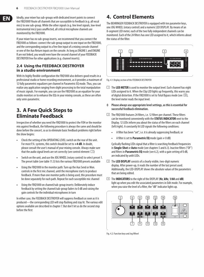
4. Control ElementsThe BEHRINGER FEEDBACK DESTROYER is equipped with ten parameter keys, one JOG WHEEL (rotary control) and a numeric LED DISPLAY. By means of an 8-segment LED meter, each of the two fully independent channels can be monitored. Each of the 24 filters has one LED assigned to it, which informs about the status of the filter.
(1) (2) (4)(3)
Fig. 4.1: Display section of the FEEDBACK DESTROYER
(1) The LED METER is used to monitor the output level. Each channel has eight LEDs assigned to it. When the Clip LED lights up frequently, this warns you of digital distortion. If the FBQ1000 is set to Total Bypass mode (see (14)), the level meter reads the input level.
◊ Please always use appropriate level settings, as this is essential for successful feedback elimination.
(2) The FBQ1000 features 24 filters, i.e. 12 filters per channel. These filters can be monitored conveniently with the STATUS INDICATOR next to the Display. 12 LEDs inform you about the status of the filters on each channel (left/right). A constantly lit LED signals the following conditions:
• A filter has been “set”, i.e. it is already suppressing feedback; or
• A filter is set to Parametric EQ mode (gain ≠ 0 dB)
Cyclically flashing LEDs signal that a filter is searching feedback frequencies in Single-Shot or Auto mode (see chapters 5 and 6.3). Inactive filters (“OF”) and filters in Parametric EQ mode (see 6.2), with a gain setting of 0 dB, are indicated by unlit LEDs.
(3) The LED DISPLAY consists of a clearly visible, two-digit numeric display. After power-up, it reads the number of the last preset used. Additionally, the LED-DISPLAY shows the absolute values of the parameters that are being edited.
(4) The INDICATORS to the right of the DISPLAY (Hz, kHz, 1/60 and dB) light up when you edit the associated parameters in Edit mode. For example, when you raise the level of a filter, the “dB” indicator lights up.
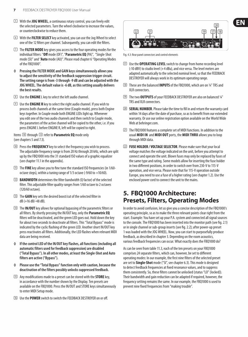
(5) (6)
(7) (9) (11) (13) (15)
(8) (10) (12) (14) (16)
Fig. 4.2: Function keys and Jog Wheel
7 FEEDBACK DESTROYER FBQ1000 User Manual
(5) With the JOG WHEEL, a continuous rotary control, you can freely edit the selected parameters. Turn the wheel clockwise to increase the values, or counterclockwise to reduce them.
(6) With the FILTER SELECT key activated, you can use the Jog Wheel to select one of the 12 filters per channel. Subsequently, you can edit the filters.
(7) The FILTER MODE key gives you access to the four operating modes for the individual filters: “Off mode (OF)”, “Parametric EQ (PA)”, “Single-Shot mode (SI)” and “Auto mode (AU)”. Please read chapter 6 “Operating Modes of the FBQ1000”.
◊ Pressing the FILTER MODE and GAIN keys simultaneously allows you to adjust the sensitivity of the feedback suppression trigger circuit. The setting range is from -3 through -9 dB and can be adjusted with the JOG WHEEL. The default value is -6 dB, as this setting usually delivers the best results.
(8) Use the ENGINE L key to select the left audio channel.
(9) Use the ENGINE R key to select the right audio channel. If you wish to process both channels at the same time (Couple mode), press both Engine keys together. In Couple mode both ENGINE LEDs light up. Whenever you edit one of the two audio channels and then switch to Couple mode, the parameters of the active channel will be copied to the other, i.e. if you press ENGINE L before ENGINE R, left will be copied to right.
Items (10) through (13) refer to Parametric EQ mode only (see chapters 5 and 7.3).
(10) Press the FREQUENCY key to select the frequency you wish to process. The adjustable frequency range is from 20 Hz through 20 kHz, which are split up by the FBQ1000 into the 31 standard ISO values of a graphic equalizer (see chapter 11.1 in the appendix).
(11) The FINE key allows you to fine tune the standard ISO frequencies (in 1/60-octave steps), within a tuning range of 1/3 octave (-9/60 to +10/60).
(12) BANDWIDTH determines the filter bandwidth (Q factor) of the selected filter. This adjustable filter quality ranges from 1/60 octave to 2 octaves (120/60 octave).
(13) The GAIN key sets the desired boost/cut of the selected filter in dB (+16 dB/-48 dB).
(14) The IN/OUT key allows for optional bypassing of the parametric filters or all filters. By shortly pressing the IN/OUT key, only the Parametric EQ filters will be deactivated, and the green LED goes out. Hold down the key for about two seconds to deactivate all filters. This “Total Bypass” mode is indicated by the cyclic flashing of the green LED. Another short IN/OUT key press reactivates all filters. Additionally, the LED flashes when relevant MIDI data are being received.
◊ If the control LED of the IN/OUT key flashes, all functions (including all automatic filters used for feedback suppression) are disabled (“Total Bypass”). In all other modes, at least the Single-Shot and Auto filters are active (“Bypass”).
◊ Please use the “Total Bypass” function only with caution, because the deactivation of the filters possibly unlocks suppressed feedback.
(15) Any modifications made to a preset can be stored with the STORE key, in accordance with the number shown by the Display. Ten presets are available on the FBQ1000. Press the IN/OUT and STORE keys simultaneously to enter MIDI Setup mode.
(16) Use the POWER switch to switch the FEEDBACK DESTROYER on or off.
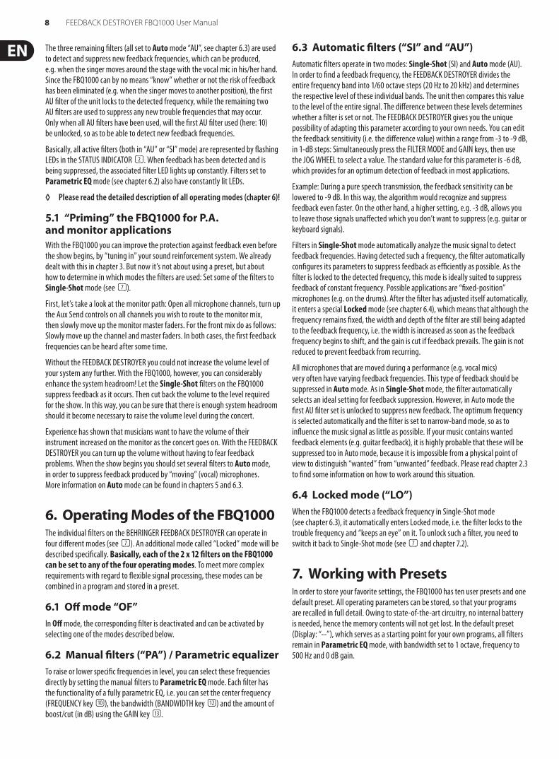
(22)
(20)
(19) (17)(21) (18)
Fig. 4.3: Rear panel connectors and control elements
(17) Use the OPERATING LEVEL switch to change from home recording level (-10 dBV) to studio level (+4 dBu), and vice versa. The level meters are adapted automatically to the selected nominal level, so that the FEEDBACK DESTROYER will always work in its optimum operating range.
(18) These are the balanced INPUTS of the FBQ1000, which are on 1/4" TRS and XLR connectors.
(19) The two OUTPUTS of your FEEDBACK DESTROYER are also on balanced 1/4" TRS and XLR connectors.
(20) SERIAL NUMBER. Please take the time to fill in and return the warranty card within 14 days after the date of purchase, so as to benefit from our extended warranty. Or use our online registration option available on the World Wide Web at behringer.com.
(21) The FBQ1000 features a complete set of MIDI functions. In addition to the usual MIDI IN and MIDI OUT ports, the MIDI THRU allows you to loop through MIDI data.
(22) FUSE HOLDER / VOLTAGE SELECTOR. Please make sure that your local voltage matches the voltage indicated on the unit, before you attempt to connect and operate the unit. Blown fuses may only be replaced by fuses of the same type and rating. Some models allow for inserting the fuse holder in two different positions, in order to switch over from 230-V to 115-V operation, and vice versa. Please note that for 115-V operation outside Europe, you need to use a fuse of a higher rating (see chapter 1.2). Use the enclosed power cord to connect the unit to the mains.
5. FBQ1000 Architecture: Presets, Filters, Operating ModesIn order to avoid confusion, let us give you a concise description of the FBQ1000’s operating principle, so as to make the three relevant points clear right from the start. Example: You have set up your P.A. system and connected all signal sources to the console. The FBQ1000 has been inserted into the monitor path (see fig. 2.1) or in single channel or sub-group inserts (see fig. 2.2); after power-up preset 1 was loaded with the JOG WHEEL. Now, you can start to purposefully produce feedback, as described in chapter 3. Depending on the room acoustics, various feedback frequencies can occur. What exactly does the FBQ1000 do?
As can be seen from table 11.3, each of the ten presets on your FBQ1000 comprises 24 separate filters, which can, however, be set to different operating modes: In our example, the first nine filters of the selected preset are set to Single-Shot mode (“SI”, see chapter 6.3). This mode is designed to detect feedback frequencies at fixed resonance values, and to suppress them consistently. So, these filters cannot be unlocked (status “LO” (locked)). Their bandwidth and gain reduction can be adapted if required, however, the frequency setting remains the same. In our example, the FBQ1000 is used to prevent nine fixed frequencies from “making trouble”.
8 FEEDBACK DESTROYER FBQ1000 User Manual
The three remaining filters (all set to Auto mode “AU”, see chapter 6.3) are used to detect and suppress new feedback frequencies, which can be produced, e.g. when the singer moves around the stage with the vocal mic in his/her hand. Since the FBQ1000 can by no means “know” whether or not the risk of feedback has been eliminated (e.g. when the singer moves to another position), the first AU filter of the unit locks to the detected frequency, while the remaining two AU filters are used to suppress any new trouble frequencies that may occur. Only when all AU filters have been used, will the first AU filter used (here: 10) be unlocked, so as to be able to detect new feedback frequencies.
Basically, all active filters (both in “AU” or “SI” mode) are represented by flashing LEDs in the STATUS INDICATOR (2). When feedback has been detected and is being suppressed, the associated filter LED lights up constantly. Filters set to Parametric EQ mode (see chapter 6.2) also have constantly lit LEDs.
◊ Please read the detailed description of all operating modes (chapter 6)!
5.1 “Priming” the FBQ1000 for P.A. and monitor applicationsWith the FBQ1000 you can improve the protection against feedback even before the show begins, by “tuning in” your sound reinforcement system. We already dealt with this in chapter 3. But now it’s not about using a preset, but about how to determine in which modes the filters are used: Set some of the filters to Single-Shot mode (see (7)).
First, let’s take a look at the monitor path: Open all microphone channels, turn up the Aux Send controls on all channels you wish to route to the monitor mix, then slowly move up the monitor master faders. For the front mix do as follows: Slowly move up the channel and master faders. In both cases, the first feedback frequencies can be heard after some time.
Without the FEEDBACK DESTROYER you could not increase the volume level of your system any further. With the FBQ1000, however, you can considerably enhance the system headroom! Let the Single-Shot filters on the FBQ1000 suppress feedback as it occurs. Then cut back the volume to the level required for the show. In this way, you can be sure that there is enough system headroom should it become necessary to raise the volume level during the concert.
Experience has shown that musicians want to have the volume of their instrument increased on the monitor as the concert goes on. With the FEEDBACK DESTROYER you can turn up the volume without having to fear feedback problems. When the show begins you should set several filters to Auto mode, in order to suppress feedback produced by “moving” (vocal) microphones. More information on Auto mode can be found in chapters 5 and 6.3.
6. Operating Modes of the FBQ1000The individual filters on the BEHRINGER FEEDBACK DESTROYER can operate in four different modes (see (7)). An additional mode called “Locked” mode will be described specifically. Basically, each of the 2 x 12 filters on the FBQ1000 can be set to any of the four operating modes. To meet more complex requirements with regard to flexible signal processing, these modes can be combined in a program and stored in a preset.
6.1 Off mode “OF”In Off mode, the corresponding filter is deactivated and can be activated by selecting one of the modes described below.
6.2 Manual filters (“PA”) / Parametric equalizerTo raise or lower specific frequencies in level, you can select these frequencies directly by setting the manual filters to Parametric EQ mode. Each filter has the functionality of a fully parametric EQ, i.e. you can set the center frequency (FREQUENCY key (10)), the bandwidth (BANDWIDTH key (12)) and the amount of boost/cut (in dB) using the GAIN key (13).
6.3 Automatic filters (“SI” and “AU”)Automatic filters operate in two modes: Single-Shot (SI) and Auto mode (AU). In order to find a feedback frequency, the FEEDBACK DESTROYER divides the entire frequency band into 1/60 octave steps (20 Hz to 20 kHz) and determines the respective level of these individual bands. The unit then compares this value to the level of the entire signal. The difference between these levels determines whether a filter is set or not. The FEEDBACK DESTROYER gives you the unique possibility of adapting this parameter according to your own needs. You can edit the feedback sensitivity (i.e. the difference value) within a range from -3 to -9 dB, in 1-dB steps: Simultaneously press the FILTER MODE and GAIN keys, then use the JOG WHEEL to select a value. The standard value for this parameter is -6 dB, which provides for an optimum detection of feedback in most applications.
Example: During a pure speech transmission, the feedback sensitivity can be lowered to -9 dB. In this way, the algorithm would recognize and suppress feedback even faster. On the other hand, a higher setting, e.g. -3 dB, allows you to leave those signals unaffected which you don’t want to suppress (e.g. guitar or keyboard signals).
Filters in Single-Shot mode automatically analyze the music signal to detect feedback frequencies. Having detected such a frequency, the filter automatically configures its parameters to suppress feedback as efficiently as possible. As the filter is locked to the detected frequency, this mode is ideally suited to suppress feedback of constant frequency. Possible applications are “fixed-position” microphones (e.g. on the drums). After the filter has adjusted itself automatically, it enters a special Locked mode (see chapter 6.4), which means that although the frequency remains fixed, the width and depth of the filter are still being adapted to the feedback frequency, i.e. the width is increased as soon as the feedback frequency begins to shift, and the gain is cut if feedback prevails. The gain is not reduced to prevent feedback from recurring.
All microphones that are moved during a performance (e.g. vocal mics) very often have varying feedback frequencies. This type of feedback should be suppressed in Auto mode. As in Single-Shot mode, the filter automatically selects an ideal setting for feedback suppression. However, in Auto mode the first AU filter set is unlocked to suppress new feedback. The optimum frequency is selected automatically and the filter is set to narrow-band mode, so as to influence the music signal as little as possible. If your music contains wanted feedback elements (e.g. guitar feedback), it is highly probable that these will be suppressed too in Auto mode, because it is impossible from a physical point of view to distinguish “wanted” from “unwanted” feedback. Please read chapter 2.3 to find some information on how to work around this situation.
6.4 Locked mode (“LO”)When the FBQ1000 detects a feedback frequency in Single-Shot mode (see chapter 6.3), it automatically enters Locked mode, i.e. the filter locks to the trouble frequency and “keeps an eye” on it. To unlock such a filter, you need to switch it back to Single-Shot mode (see (7) and chapter 7.2).
7. Working with PresetsIn order to store your favorite settings, the FBQ1000 has ten user presets and one default preset. All operating parameters can be stored, so that your programs are recalled in full detail. Owing to state-of-the-art circuitry, no internal battery is needed, hence the memory contents will not get lost. In the default preset (Display: “--”), which serves as a starting point for your own programs, all filters remain in Parametric EQ mode, with bandwidth set to 1 octave, frequency to 500 Hz and 0 dB gain.
9 FEEDBACK DESTROYER FBQ1000 User Manual
7.1 Recalling presetsThe FEEDBACK DESTROYER has ten presets, which can be overwritten. After power-up, the unit restores the last preset used. Use the JOG WHEEL to select another preset. The default preset is located before the first program.
◊ Please note that the FEEDBACK DESTROYER generally activates the newly selected presets only after about one second, which is indicated by a dot in the lower right corner of the DISPLAY. After loading the data, the FEEDBACK DESTROYER enables the preset and the dot disappears. This brief interruption of the signal path avoids the direct activation of each preset, as you scroll through the preset list with the Jog Wheel. Thus, the FBQ1000 makes sure that no “unwanted” programs are loaded unintentionally. Additionally, you can rotate the Jog Wheel at high speed and still have the time to specifically select the preset of your choice, instead of any of its “neighbors”.
7.2 Selecting the filter operating modeEach filter mode has two letters assigned to it, which appear in the DISPLAY after pressing the FILTER MODE key. The following display messages are available:
Display Operating mode
OF Off
PA Parametric EQ
AU Auto
SI Single-Shot
LO Locked
Tab. 7.1: FEEDBACK DESTROYER filter operating modes
As already mentioned, the operating mode of a filter can be changed as follows: Press the FILTER SELECT key and specify the filter number (1 through 12) with the Jog Wheel. Using the two ENGINE keys, you can select the left (ENGINE L) or right audio channel (ENGINE R), or both at the same time by pressing the two ENGINE keys simultaneously.
Now, press the FILTER MODE key and select the mode of your choice with the Jog Wheel. The display message “LO” (= “Locked”) informs you that a filter set to Single-Shot mode before is already suppressing feedback. As described in chapter 6.4, this filter is set to Locked mode automatically. You can unlock such a filter by switching it back to Single-Shot mode. As soon as a new feedback frequency will be found, the FEEDBACK DESTROYER switches the filter from the old frequency to the new one. If you leave Auto or Single-Shot mode and enter parametric EQ mode, the filter’s parameter settings remain unchanged.
◊ To avoid inadvertent changing of filter modes, the filter mode selection takes place after about one second, which is indicated by a dot in the lower right corner of the Display.
◊ Press the FILTER MODE and GAIN keys at the same time, and use the JOG WHEEL to adjust the feedback threshold (= feedback sensitivity) within a range from -3 to -9 dB.
7.3 Editing filter parameters◊ Remember: Your FBQ1000 has ten pre-configured user presets,
each comprising 12 filters per channel. Each individual filter can be selected in any of the four operating modes!
◊ However, the “Locked” mode cannot be selected directly: when a filter which was selected as “Single-Shot” detects a feedback frequency, the filter is automatically set and “locked”, i.e. the filter is locked to the problem frequency and “keeps an eye” on it.
◊ In Single-Shot and Auto modes, the filter parameter cannot be edited but only displayed. Editing can be done in Parametric EQ mode only:
To change filter settings manually, the respective filter must be set to Parametric EQ mode. Press and keep the FILTER MODE key for about one second. Now, you can adapt the frequency after pressing FREQUENCY. Depending on the preset frequency, either the “Hz” or the “kHz” indicator to the right of the DISPLAY lights up. For example, when the filter is set to 160 Hz, the numeric Display will read the value and the “Hz” indicator lights up. To raise the frequency to 2,700 Hz, turn the Jog Wheel clockwise until the ISO frequency (2.5 kHz; see Tab. 11.2) next to this value appears in the Display and the “kHz” indicator lights up. The FINE key allows you to fine tune the chosen standard ISO frequency within a tuning range of 1/3 octave (in 1/60-octave steps). The mathematical proportion between the displayed value and the absolute frequency, as well as a guide to find the desired frequency quickly, are listed in the appendix (chapter 11.1 – frequency chart). The bandwidth of the filter (quality) can be adjusted by selecting the BANDWIDTH key. The adjustable bandwidth ranges from 2 octaves down to 1/60 octave. By pressing the GAIN key, it is possible to set the desired boost or cut of the selected frequency. A “+” or “-” signals that the level is being increased or decreased respectively.
◊ Filters in Single-Shot or Auto mode can be transformed into parametric filters with the same frequency, quality and 0 dB gain by pressing the FILTER MODE key for about one second. Only then will it be possible to edit the filter parameters.
7.4 Storing presetsWhenever you edit a preset, the LED in the STORE key starts flashing. Basically, all edits in Parametric EQ mode and the filter deactivation in Off mode can be stored. Filters in Single-Shot or Auto mode adjust and store their parameters automatically. However, these data will get lost when you switch off the unit. To avoid that, please write the edited setting to a preset before you switch the FBQ1000 off:
Press the STORE key once, so that the DISPLAY starts flashing. If you wish to preserve the original preset, use the Jog Wheel to select another preset number, which can be overwritten. Then, press STORE again to save your edits to the selected preset. If you wish to overwrite the original preset, simply press the STORE key twice after editing, so as to save all edits to the same preset.
7.5 Restoring the factory presetsPress and keep the FILTER SELECT and STORE keys pressed before you switch on the FEEDBACK DESTROYER. After power-up keep the switches pressed for another second. The preset numbers are counted up and the presets are reset to their original default values.
10 FEEDBACK DESTROYER FBQ1000 User Manual
8. Problems Do Have A Cause ...Feedback is one of the major problems encountered in live P.A. applications. In a worst-case scenario every microphone signal passing an amplifier can cause feedback. Still, there’s a lot you can do even before the show begins:
• Place the microphones at some distance to the FOH and monitor speakers
• Make sure that the levels of the microphone channels are adjusted correctly (see user’s manual of your console)
• Use the microphones according to their polar patterns (e.g. omnidirectional, cardioid, super-cardioid)
• Poor room acoustics should be improved. Tiled walls and floors, which are highly reflective, can be covered with curtains or carpet
• Use a graphic equalizer to adapt the overall sound to the room acoustics
• To a certain degree, feedback can also be suppressed manually with a graphic EQ
9. MIDI ControlUse the MIDI key combination to select the MIDI parameters you wish to adjust. To do so, press and keep the IN/OUT and STORE keys at the same time. All parameters can be edited with the JOG WHEEL and these two keys. The MIDI menu includes six pages, which you can select by pressing the IN/OUT key (forward) and the STORE key (backward) several times.
On the first page, you can select the MIDI channel. The DISPLAY reads a small “c” (= channel). The JOG WHEEL adjusts a channel from 1 through 16. To switch off the MIDI function, simply select “0” (displayed as “-”).
On the second page, you can select MIDI Omni mode, i.e. the unit transmits/receives on all 16 MIDI channels. The DISPLAY reads “O” (= Omni). Use the JOG WHEEL to activate (“1”) or deactivate (“0”) MIDI Omni mode.
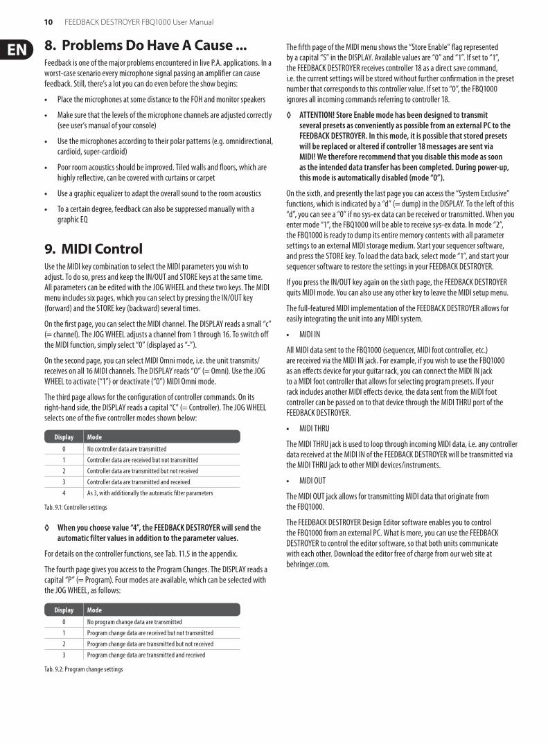
The third page allows for the configuration of controller commands. On its right-hand side, the DISPLAY reads a capital “C” (= Controller). The JOG WHEEL selects one of the five controller modes shown below:
Display Mode
0 No controller data are transmitted
1 Controller data are received but not transmitted
2 Controller data are transmitted but not received
3 Controller data are transmitted and received
4 As 3, with additionally the automatic filter parameters
Tab. 9.1: Controller settings
◊ When you choose value “4”, the FEEDBACK DESTROYER will send the automatic filter values in addition to the parameter values.
For details on the controller functions, see Tab. 11.5 in the appendix.
The fourth page gives you access to the Program Changes. The DISPLAY reads a capital “P” (= Program). Four modes are available, which can be selected with the JOG WHEEL, as follows:
Display Mode
0 No program change data are transmitted
1 Program change data are received but not transmitted
2 Program change data are transmitted but not received
3 Program change data are transmitted and received
Tab. 9.2: Program change settings
The fifth page of the MIDI menu shows the “Store Enable” flag represented by a capital “S” in the DISPLAY. Available values are “0” and “1”. If set to “1”, the FEEDBACK DESTROYER receives controller 18 as a direct save command, i.e. the current settings will be stored without further confirmation in the preset number that corresponds to this controller value. If set to “0”, the FBQ1000 ignores all incoming commands referring to controller 18.
◊ ATTENTION! Store Enable mode has been designed to transmit several presets as conveniently as possible from an external PC to the FEEDBACK DESTROYER. In this mode, it is possible that stored presets will be replaced or altered if controller 18 messages are sent via MIDI! We therefore recommend that you disable this mode as soon as the intended data transfer has been completed. During power-up, this mode is automatically disabled (mode “0”).
On the sixth, and presently the last page you can access the “System Exclusive” functions, which is indicated by a “d” (= dump) in the DISPLAY. To the left of this “d”, you can see a “0” if no sys-ex data can be received or transmitted. When you enter mode “1”, the FBQ1000 will be able to receive sys-ex data. In mode “2”, the FBQ1000 is ready to dump its entire memory contents with all parameter settings to an external MIDI storage medium. Start your sequencer software, and press the STORE key. To load the data back, select mode “1”, and start your sequencer software to restore the settings in your FEEDBACK DESTROYER.
If you press the IN/OUT key again on the sixth page, the FEEDBACK DESTROYER quits MIDI mode. You can also use any other key to leave the MIDI setup menu.
The full-featured MIDI implementation of the FEEDBACK DESTROYER allows for easily integrating the unit into any MIDI system.
• MIDI IN
All MIDI data sent to the FBQ1000 (sequencer, MIDI foot controller, etc.) are received via the MIDI IN jack. For example, if you wish to use the FBQ1000 as an effects device for your guitar rack, you can connect the MIDI IN jack to a MIDI foot controller that allows for selecting program presets. If your rack includes another MIDI effects device, the data sent from the MIDI foot controller can be passed on to that device through the MIDI THRU port of the FEEDBACK DESTROYER.
• MIDI THRU
The MIDI THRU jack is used to loop through incoming MIDI data, i.e. any controller data received at the MIDI IN of the FEEDBACK DESTROYER will be transmitted via the MIDI THRU jack to other MIDI devices/instruments.
• MIDI OUT
The MIDI OUT jack allows for transmitting MIDI data that originate from the FBQ1000.
The FEEDBACK DESTROYER Design Editor software enables you to control the FBQ1000 from an external PC. What is more, you can use the FEEDBACK DESTROYER to control the editor software, so that both units communicate with each other. Download the editor free of charge from our web site at behringer.com.
11 FEEDBACK DESTROYER FBQ1000 User Manual
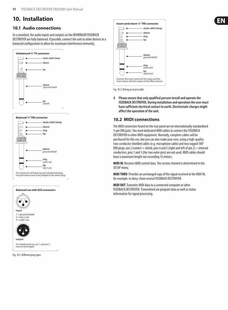
10. Installation10.1 Audio connectionsAs a standard, the audio inputs and outputs on the BEHRINGER FEEDBACK DESTROYER are fully balanced. If possible, connect the unit to other devices in a balanced configuration to allow for maximum interference immunity.
strain relief clamp
sleeveringtip
sleeveground/shield
For connection of balanced and unbalanced plugs,ring and sleeve have to be bridged at the stereo plug.
Balanced ¼" TRS connector
ringcold (-ve)tiphot (+ve)
output
For unbalanced use, pin 1 and pin 3 have to be bridged
1 = ground/shield2 = hot (+ve)3 = cold (-ve)
input
123
1 2
3
Balanced use with XLR connectors
Fig. 10.1: Different plug types
strain relief clamp
sleeveringtip
sleeveground/shield
Connect the insert send with the input and theinsert return with the output of the e�ects device.
Insert send return ¼" TRS connector
ringreturn (in)tipsend (out)
Fig. 10.2: Wiring an insert cable
◊ Please ensure that only qualified persons install and operate the FEEDBACK DESTROYER. During installation and operation the user must have sufficient electrical contact to earth. Electrostatic charges might affect the operation of the unit.
10.2 MIDI connectionsThe MIDI connectors found on the rear panel are on internationally standardized 5-pin DIN jacks. You need dedicated MIDI cables to connect the FEEDBACK DESTROYER to other MIDI equipment. Normally, complete cables will be purchased for this use, but you can also make your own, using a high-quality two-conductor shielded cables (e.g. microphone cable) and two rugged 180° DIN plugs: pin 2 (center) = shield, pins 4 and 5 (right and left of pin 2) = internal conductors, pins 1 and 3 (the two outer pins) are not used. MIDI cables should have a maximum length not exceeding 15 meters.
MIDI IN: Receives MIDI control data. The receive channel is determined in the SETUP menu.
MIDI THRU: Provides an unchanged copy of the signal received at the MIDI IN, for example, to daisy-chain several FEEDBACK DESTROYER.
MIDI OUT: Transmits MIDI data to a connected computer or other FEEDBACK DESTROYER. Transmitted are program data as well as status information for signal processing.
strain relief clamp
sleeve
tip
sleeve(ground/shield)
Unbalanced ¼" TS connector
tip(signal)
12 FEEDBACK DESTROYER FBQ1000 User Manual
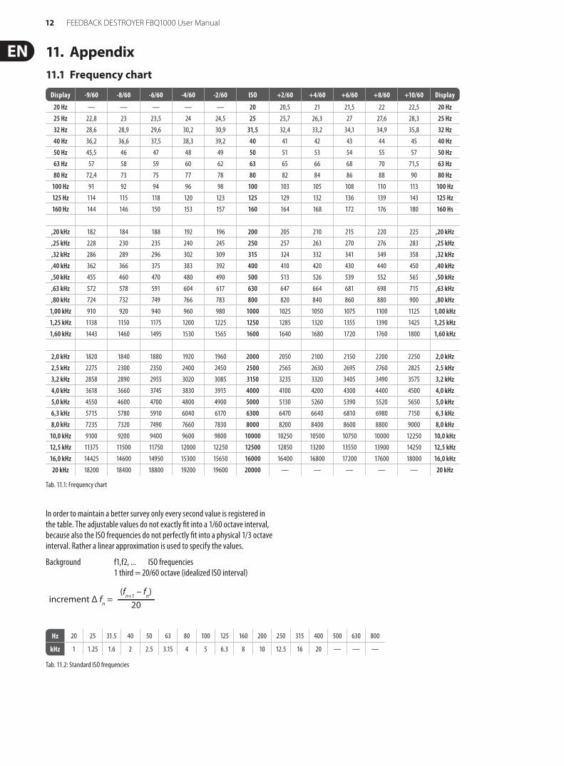
11. Appendix11.1 Frequency chart
Display -9/60 -8/60 -6/60 -4/60 -2/60 ISO +2/60 +4/60 +6/60 +8/60 +10/60 Display
20 Hz — — — — — 20 20,5 21 21,5 22 22,5 20 Hz
25 Hz 22,8 23 23,5 24 24,5 25 25,7 26,3 27 27,6 28,3 25 Hz
32 Hz 28,6 28,9 29,6 30,2 30,9 31,5 32,4 33,2 34,1 34,9 35,8 32 Hz
40 Hz 36,2 36,6 37,5 38,3 39,2 40 41 42 43 44 45 40 Hz
50 Hz 45,5 46 47 48 49 50 51 53 54 55 57 50 Hz
63 Hz 57 58 59 60 62 63 65 66 68 70 71,5 63 Hz
80 Hz 72,4 73 75 77 78 80 82 84 86 88 90 80 Hz
100 Hz 91 92 94 96 98 100 103 105 108 110 113 100 Hz
125 Hz 114 115 118 120 123 125 129 132 136 139 143 125 Hz
160 Hz 144 146 150 153 157 160 164 168 172 176 180 160 Hs
,20 kHz 182 184 188 192 196 200 205 210 215 220 225 ,20 kHz
,25 kHz 228 230 235 240 245 250 257 263 270 276 283 ,25 kHz
,32 kHz 286 289 296 302 309 315 324 332 341 349 358 ,32 kHz
,40 kHz 362 366 375 383 392 400 410 420 430 440 450 ,40 kHz
,50 kHz 455 460 470 480 490 500 513 526 539 552 565 ,50 kHz
,63 kHz 572 578 591 604 617 630 647 664 681 698 715 ,63 kHz
,80 kHz 724 732 749 766 783 800 820 840 860 880 900 ,80 kHz
1,00 kHz 910 920 940 960 980 1000 1025 1050 1075 1100 1125 1,00 kHz
1,25 kHz 1138 1150 1175 1200 1225 1250 1285 1320 1355 1390 1425 1,25 kHz
1,60 kHz 1443 1460 1495 1530 1565 1600 1640 1680 1720 1760 1800 1,60 kHz
2,0 kHz 1820 1840 1880 1920 1960 2000 2050 2100 2150 2200 2250 2,0 kHz
2,5 kHz 2275 2300 2350 2400 2450 2500 2565 2630 2695 2760 2825 2,5 kHz
3,2 kHz 2858 2890 2955 3020 3085 3150 3235 3320 3405 3490 3575 3,2 kHz
4,0 kHz 3618 3660 3745 3830 3915 4000 4100 4200 4300 4400 4500 4,0 kHz
5,0 kHz 4550 4600 4700 4800 4900 5000 5130 5260 5390 5520 5650 5,0 kHz
6,3 kHz 5715 5780 5910 6040 6170 6300 6470 6640 6810 6980 7150 6,3 kHz
8,0 kHz 7235 7320 7490 7660 7830 8000 8200 8400 8600 8800 9000 8,0 kHz
10,0 kHz 9100 9200 9400 9600 9800 10000 10250 10500 10750 10000 12250 10,0 kHz
12,5 kHz 11375 11500 11750 12000 12250 12500 12850 13200 13550 13900 14250 12,5 kHz
16,0 kHz 14425 14600 14950 15300 15650 16000 16400 16800 17200 17600 18000 16,0 kHz
20 kHz 18200 18400 18800 19200 19600 20000 — — — — — 20 kHz
Tab. 11.1: Frequency chart
In order to maintain a better survey only every second value is registered in the table. The adjustable values do not exactly fit into a 1/60 octave interval, because also the ISO frequencies do not perfectly fit into a physical 1/3 octave interval. Rather a linear approximation is used to specify the values.
Background f1,f2, ... ISO frequencies 1 third = 20/60 octave (idealized ISO interval)
Hz 20 25 31.5 40 50 63 80 100 125 160 200 250 315 400 500 630 800
kHz 1 1.25 1.6 2 2.5 3.15 4 5 6.3 8 10 12.5 16 20 — — —
Tab. 11.2: Standard ISO frequencies
increment Δ fn =
(fn+1 – f
n)
20
13 FEEDBACK DESTROYER FBQ1000 User Manual
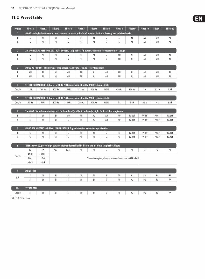
11.2 Preset table
Preset Filter 1 Filter 2 Filter 3 Filter 4 Filter 5 Filter 6 Filter 7 Filter 8 Filter 9 Filter 10 Filter 11 Filter 12
1 MONO: 9 single shot filters attenuate room resonances before 3 automatic filters destroy variable feedbacks
L SI SI SI SI SI SI SI SI SI AU AU AU
R SI SI SI SI SI SI SI SI SI AU AU AU
2 2 x MONITOR AS FEEDBACK DESTROYER ONLY: 7 single shots / 5 automatic filters for most monitor setups
L SI SI SI SI SI SI SI AU AU AU AU AU
R SI SI SI SI SI SI SI AU AU AU AU AU
3 MONO AUTO PILOT: 12 Filters per channel constantly chase and destroy feedbacks
L AU AU AU AU AU AU AU AU AU AU AU AU
R AU AU AU AU AU AU AU AU AU AU AU AU
4 STEREO PARAMETRIC EQ: Preset with 12 ISO frequencies, all set to 1/3 Oct., Gain + 0 dB
Couple 125 Hz 160 Hz 200 Hz 250 Hz 315 Hz 400 Hz 500 Hz 630 Hz 800 Hz 1 k 1.25 k 1.6 k
5 STEREO PARAMETRIC EQ: Preset with 12 ISO frequencies, all set to 2/3 Oct., Gain + 0 dB
Couple 40 Hz 63 Hz 100 Hz 160 Hz 250 Hz 400 Hz 630 Hz 1 k 1.6 k 2.5 k 4 k 6.3 k
6 2 x MONO: Sample monitoring, left for handheld (lead) microphone(s), right for fixed (backing) ones
L SI SI SI AU AU AU AU AU PA def PA def PA def PA def
R SI SI SI SI SI AU AU AU PA def PA def PA def PA def
7 MONO PARAMETRIC AND SINGLE SHOT FILTERS: A good start for a monitor equalization
L SI SI SI SI SI SI SI SI PA def PA def PA def PA def
R SI SI SI SI SI SI SI SI PA def PA def PA def PA def
8 STEREO FOH EQ, providing 4 parametric EQ's (low roll off in filter 1 and 2), plus 8 single shot filters
Couple
PA PA PA d. PA d. SI SI SI SI SI SI SI SI
40 Hz 80 Hz
Channels coupled, changes on one channel are valid for both1 Oct. 1 Oct.
-8 dB -4 dB
9 MONO FREE
L, RSI SI SI SI SI SI SI AU AU PA PA PA
SI SI SI SI SI SI SI AU AU PA PA PA
10z STEREO FREE
Couple SI SI SI SI SI SI SI AU AU PA PA PA
Tab. 11.3: Preset table
14 FEEDBACK DESTROYER FBQ1000 User Manual
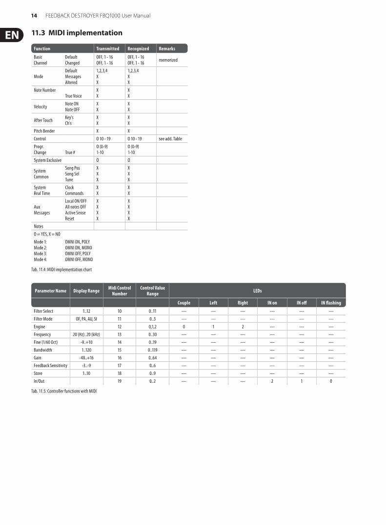
11.3 MIDI implementation
Tab. 11.4: MIDI implementation chart
Function Transmitted Recognized Remarks
BasicChannel
DefaultChanged
OFF, 1 - 16OFF, 1 - 16
OFF, 1 - 16OFF, 1 - 16 memorized
ModeDefaultMessagesAltered
1,2,3,4XX
1,2,3,4XX
Note NumberTrue Voice
XX
XX
Velocity Note ONNote OFF
XX
XX
After Touch Key'sCh's
XX
XX
Pitch Bender X X
Control O 10 - 19 O 10 - 19 see add. Table
Progr.Change True #
O (0-9)1-10
O (0-9)1-10
System Exclusive O O
SystemCommon
Song PosSong SelTune
XXX
XXX
SystemReal Time
ClockCommands
XX
XX
AuxMessages
Local ON/OFFAll notes OFFActive SenseReset
XXXX
XXXX
Notes
O = YES, X = NO
Mode 1:Mode 2:Mode 3:Mode 4:
OMNI ON, POLYOMNI ON, MONOOMNI OFF, POLYOMNI OFF, MONO
Parameter Name Display Range Midi Control Number
Control Value Range LEDs
Couple Left Right IN on IN off IN flashing
Filter Select 1..12 10 0..11 — — — — — —
Filter Mode OF, PA, AU, SI 11 0..3 — — — — — —
Engine 12 0,1,2 0 1 2 — — —
Frequency 20 (Hz)..20 (kHz) 13 0..30 — — — — — —
Fine (1/60 Oct) -9..+10 14 0..19 — — — — — —
Bandwidth 1..120 15 0..119 — — — — — —
Gain -48..+16 16 0..64 — — — — — —
Feedback Sensitivity -3..-9 17 0..6 — — — — — —
Store 1..10 18 0..9 — — — — — —
In/Out 19 0..2 — — — 2 1 0
Tab. 11.5: Controller functions with MIDI
15 FEEDBACK DESTROYER FBQ1000 User Manual
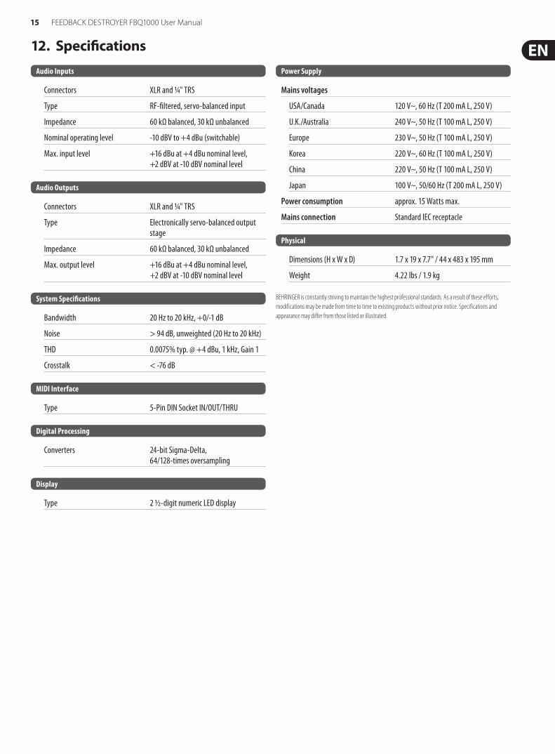
12. Specifications
Audio Inputs
Connectors XLR and 1/4" TRS
Type RF-filtered, servo-balanced input
Impedance 60 kΩ balanced, 30 kΩ unbalanced
Nominal operating level -10 dBV to +4 dBu (switchable)
Max. input level +16 dBu at +4 dBu nominal level, +2 dBV at -10 dBV nominal level
Audio Outputs
Connectors XLR and 1/4" TRS
Type Electronically servo-balanced output stage
Impedance 60 kΩ balanced, 30 kΩ unbalanced
Max. output level +16 dBu at +4 dBu nominal level, +2 dBV at -10 dBV nominal level
System Specifications
Bandwidth 20 Hz to 20 kHz, +0/-1 dB
Noise > 94 dB, unweighted (20 Hz to 20 kHz)
THD 0.0075% typ. @ +4 dBu, 1 kHz, Gain 1
Crosstalk < -76 dB
MIDI Interface
Type 5-Pin DIN Socket IN/OUT/THRU
Digital Processing
Converters 24-bit Sigma-Delta, 64/128-times oversampling
Display
Type 2 ½-digit numeric LED display
Power Supply
Mains voltages
USA/Canada 120 V~, 60 Hz (T 200 mA L, 250 V)
U.K./Australia 240 V~, 50 Hz (T 100 mA L, 250 V)
Europe 230 V~, 50 Hz (T 100 mA L, 250 V)
Korea 220 V~, 60 Hz (T 100 mA L, 250 V)
China 220 V~, 50 Hz (T 100 mA L, 250 V)
Japan 100 V~, 50/60 Hz (T 200 mA L, 250 V)
Power consumption approx. 15 Watts max.
Mains connection Standard IEC receptacle
Physical
Dimensions (H x W x D) 1.7 x 19 x 7.7" / 44 x 483 x 195 mm
Weight 4.22 lbs / 1.9 kg
BEHRINGER is constantly striving to maintain the highest professional standards. As a result of these efforts, modifications may be made from time to time to existing products without prior notice. Specifications and appearance may differ from those listed or illustrated.
16 FEEDBACK DESTROYER FBQ1000 User Manual
FEDERAL COMMUNICATIONS COMMISSION COMPLIANCE INFORMATION
Responsible Party Name: MUSIC Group Services US Inc.
Address: 18912 North Creek Parkway, Suite 200 Bothell, WA 98011, USA
Phone/Fax No.: Phone: +1 425 672 0816 Fax: +1 425 673 7647
FEEDBACK DESTROYER FBQ1000
complies with the FCC rules as mentioned in the following paragraph:
This equipment has been tested and found to comply with the limits for a Class B digital device, pursuant to part 15 of the FCC Rules. These limits are designed to provide reasonable protection against harmful interference in a residential installation. This equipment generates, uses and can radiate radio frequency energy and, if not installed and used in accordance with the instructions, may cause harmful interference to radio communications. However, there is no guarantee that interference will not occur in a particular installation. If this equipment does cause harmful interference to radio or television reception, which can be determined by turning the equipment off and on, the user is encouraged to try to correct the interference by one or more of the following measures:
• Reorient or relocate the receiving antenna.
• Increase the separation between the equipment and receiver.
• Connect the equipment into an outlet on a circuit different from that to which the receiver is connected.
• Consult the dealer or an experienced radio/TV technician for help.
This device complies with Part 15 of the FCC rules. Operation is subject to the following two conditions:
(1) this device may not cause harmful interference, and (2) this device must accept any interference received, including interference that may cause undesired operation.
Important information:
Changes or modifications to the equipment not expressly approved by MUSIC Group can void the user’s authority to use the equipment.
FEEDBACK DESTROYER FBQ1000

We Hear You